Embed Size (px)
Citation preview
Canals in South Florida Appendix A: Basic Concepts, Glossary of Terms and Abbreviations
A-1
Canals in South Florida: A Technical Support Document
Appendix A
Basic Concepts, Glossary of Terms and Abbreviations
Page Basic Concepts A-2
Hydrologic Terminology A-7
Glossary of Technical Terms A-10
Acronyms and Abbreviations A-19
Units of Measurement A-22
Canals in South Florida Appendix A: Basic Concepts, Glossary of Terms and Abbreviations
A-2
APPENDIX A
BASIC CONCEPTS, HYDROLOGIC TERMINOLOGY, GLOSSARY OF TERMS AND ABBREVIATIONS
Basic Concepts
Runoff and Drainage Several things can happen to rain after it falls to earth. At the beginning of a rain event, the rain will most likely seep into, or "infiltrate", the soil. As soil becomes saturated, however, the rain will tend to pool on the surface of the ground in puddles or ponds. These detention areas have only a limited storage volume, and when their capacity is exceeded, the excess water will flow downhill to the nearest stream or canal. That part of the rainfall that "runs off" of the soil surface to enter local streams is termed "surface runoff". Of the water that is detained on the surface, some will evaporate and the balance will eventually seep into the ground.
Water seeping into the ground enters a reservoir of subsurface water known as groundwater. Since, in south Florida, many soils are very sandy and underlying rock strata tend to be very porous, water flows easily between surface water and groundwater. The surface of the groundwater is known as the "water table". When the water table level is higher than local surface water levels (in canals, streams and lakes), water will enter the surface water from groundwater. When the water table is lower than the local surface water level, flow is from surface water to groundwater. In general, groundwater supplements stream flow during periods of low rainfall, and surface water recharges groundwater storage during periods of high rainfall. Although subsurface flow from groundwater to surface water is important to the long term supply of water to a canal or stream (it is sometimes referred to as "base flow"), it does not make significant contributions, if at all, to stream flow during storm events with high rainfall.
In the context of these basin descriptions, the term drainage is used to refer to the total surface and subsurface flows entering a canal from its drainage basin. It may be useful to keep in mind, however, that during a rain event (especially one severe enough to cause flooding), it is surface runoff that is the important contributor to this flow, and at times between rain events, subsurface flow from groundwater to surface water is most important.
Runoff from an area is influenced by several factors: how much rain has fallen recently, the depth to the water table, and how the land in the area is used. The amount of recent rainfall and the depth to the water table dictate how much water is in the soil. The degree to which the soil is saturated, in turn, determines how much of the falling rain may infiltrate the soil, and thus, how much of the rain will run off to local streams.
Land use has a large impact on the amount of surface runoff entering local streams and canals. For example, much of the surface area in an urban area (e.g., roofs, roads, and parking lots) is impervious to water. Almost all the rain impacting impervious areas becomes surface runoff. Some water may be detained and will evaporate, but the percentage of rainfall that enters local
Canals in South Florida Appendix A: Basic Concepts, Glossary of Terms and Abbreviations
A-3
canals or streams by surface flow in an urban area can be quite high. As a result, urban areas may be subject to high stream flows (flooding) during rain events.
A vegetated area can intercept and retain a large part of the rainfall, and subsequent surface runoff from a rain event. This intercepted water has an additional opportunity to evaporate or seep into the ground. In general, a smaller percentage of the rain falling on a vegetated area will enter local streams and canals as surface runoff than a comparable urban area. As a result, stream flows in vegetated areas are moderated compared to urban areas.
Water Surface Elevation A water surface elevation in a canal is the distance from the water's surface to some reference elevation or "datum". In the District, all elevations are relative to the National Geodetic Vertical Datum (NGVD). Water surface elevations are measured in feet (ft). Water surface elevations may also be referred to as "stages".
Important water surface elevations are the headwater and the tailwater stages at the control structures (see Control Structures). The difference between these stages will affect the flow through or over the structure. Gravity flow is always from the highest to lowest water surface elevation and, in general, flow increases as the difference in water surface elevation increases. In some basins, pumps are used to move water from lower to higher water surface elevations. Note that because of the flat topography in much of south Florida, water surface elevations may be independent of ground surface elevations. In these cases, it is possible for water to flow uphill relative to the ground surface.
The headwater side of a gravity flow structure is the side on which the stage is usually higher. The caveat is necessary since it is possible at some structures for the tailwater to occasionally be higher than the headwater stage. The headwater stage at a pumping station is usually defined as the side from which water is pumped and usually refers to the side with the lower stage. This convention allows the direction of water flow to be defined as from the headwater to the tailwater side in both cases.
Water surface elevations elsewhere in the canal are also important. Obviously, if the stage exceeds the elevation of the top of the canal, flooding will result. Not as obvious is the fact that the stage in the canal largely determines the water table elevation of the local groundwater (see Runoff and Drainage). The stage in the lower reaches (near the ocean) of some canals is maintained at levels high enough to prevent intrusions of saltwater into the local groundwater. In other areas, stages are maintained that keep water table elevations low enough to prevent drainage problems in low lying areas.
Design Storm/Design Discharge The design storm for a basin is the most severe storm for which the canals and water control structures in the basin will accommodate that storm's runoff without an unacceptable level of flooding occurring in the basin. Sometimes a basin is described as having "flood protection “up to a certain design storm.” The level of protection is the flood level at which flood damages not eliminated by the Project are considered relatively minor and are economically acceptable.
A severe storm is described by the frequency with which it may occur. On a long-term average, a storm of given intensity may occur, for example, once in every 25 years (i.e., the storm has a four percent chance of being equaled or exceeded in any given year). This is written as 1-25
Canals in South Florida Appendix A: Basic Concepts, Glossary of Terms and Abbreviations
A-4
years and is read as one in 25 years. It must be emphasized, however, that a storm of a given intensity can occur at any time regardless of the frequency assigned to it. For example, two severe storms, of an intensity that occurs on average only once in every one hundred years (1-100 year storm), occurred in northern Palm Beach County within three months of each other in the early 1980s.
The U.S. Army Corps of Engineers (USACE) specifies a Standard Project Storm (SPS) for South Florida. The rainfall amounts for the SPS are those for a 1-100 year storm increased by 25 percent. The storm is assumed to occur during a hurricane, or the wet season, when water tables are high and soils are wet. These conditions will maximize the runoff from the storm. The SPS is intended to be reasonably characteristic of large storms that have or could occur in the Project area. The runoff from the SPS is designated the Standard Project Flood (SPF). The capacity of a canal and its structures may be given as a percentage of the SPF (e.g. 40 percent SPF). The storm that would generate this amount of runoff is given by its frequency (e.g., 1-10 years). Note that it is implicitly assumed that these storms occur for antecedent weather conditions that will maximize the runoff from the storm in the basin of interest.
A severe storm of a certain frequency may not generate the same amount of runoff in different basins of the same size even when antecedent weather conditions or water table elevations for the basins are similar. Land use in the basins will affect the relative amounts of surface runoff to be expected from the basins (see Runoff and Drainage). Urban areas will often have more surface runoff than will more vegetated areas.
The amount of runoff to be expected per unit area for design storms at various recurrence intervals, antecedent conditions, and land use can be found in the USACE General Design Memorandums for the Project. The runoff calculated to occur for a given set of storm frequency, antecedent conditions, and land use is the design discharge.
Levee A levee is any artificial barrier together with appurtenant works that will divert or restrain the flow of a stream or other body of water for the purpose of creating an impoundment or protecting an area from inundation by flood waters. The terms dike and levee are often used interchangeably. The large earthworks that surround Lake Okeechobee are generally referred to as dikes, whereas the smaller earthworks surrounding the Water Conservation Areas are generally called levees. In South Florida, levees have been constructed to block overland flow, to protect areas from flooding, to create impoundments for water storage, or create drainage divides to divert flows in a particular direction, or simply as artifacts of canal construction. A special type of levee, referred to as a “tieback” levee may be constructed across adjacent water bodies or wetlands to prevent flow around structures. Such tieback levees are used along the Kissimmee River floodplain to connect the central water control structures on the River to the adjacent uplands on either side of the floodplain. Levees built in wetlands can create habitat diversity by providing dry land that can support colonization by upland species of grasses trees and shrubs. They also create disturbed areas that may be readily invaded by exotic species such as Brazilian pepper and Australian Pines.
Canals in South Florida Appendix A: Basic Concepts, Glossary of Terms and Abbreviations
A-5
Drainage systems (primary, secondary, and tertiary) The primary drainage system in South Florida consists of the canals and associated features that are managed by the SFWMD and USACE. Secondary systems consist of canals and features that are managed by designated drainage Districts or private entities, which may discharge to the coast or receiving lakes, or into the primary system. Such secondary systems operate under permits issued by the water management district. Tertiary systems consist of canals and features generally located on private lands that provide localized drainage and discharge into retention/detention areas or into secondary systems. Such systems generally operate, and are regulated by, under an Environmental Resource Permit issued by the SFWMD
Drainage Basin, Watershed, and Sub-basin If rains falls over a large enough area, some of the runoff from that storm will likely enter one stream, and some of it will enter another stream. It is said that those streams "drain" different basins or that they are in different "drainage basins." The drainage basin of a stream is all the land that contributes runoff to the stream or its tributaries. It is usually specified as that land which drains to the stream upstream of a given point, such as the mouth of the stream.
The boundary between drainage basins is termed a "divide." Runoff is divided along the boundary, with runoff on one side of the boundary flowing to one stream and runoff on the other side of the boundary flowing to another stream. In a highly managed system such as the Central and Southern Florida Project, a somewhat different definition is useful. For purposes of this Atlas, a basin is considered to be an area bounded by levees and roadways, and less frequently by natural ridges and high ground, where all surface water inflows to and outflows from the area are managed in some way (i.e., controlled by a weir, spillway, culvert, or pump station); hence, the term "surface water management basin".
Water Control Structures The structures referred to in this document are hydraulic works (i.e. spillways, culverts, and weirs) located in the canals to control water surface elevation (stage divide) or amount of flow (stage divide or water supply structure).
The Project control structures are generally designed to regulate the flow of water in the canals and water levels in the lakes. Their primary use is to discharge excess water from the lakes during flooding, to provide environmentally desirable fluctuations, and to maintain minimum water levels in the aquifers, canals and lakes to prevent over-drainage, and in the case of coastal canals, to control saltwater intrusion The purposes of water control are typically to: (1) To maintain optimum water control stages in upstream lakes and canals, (2) to pass the design flood (e.g. 30 percent of the SPF) without exceeding the upstream flood design stage, (3) to restrict downstream flood stages and channel velocities to non-damaging levels, and (4) to pass sufficient discharge during low-flow periods to maintain downstream stages. For structures located adjacent to lakes, and additional function is to (5) prevent overtopping of the structure by waves breaking against the structure during the design storm and wind tide.
Hydraulic Analysis The hydraulic profile of a canal is represented by a number of water surface elevations taken along its length. The water surface elevations are a function of the amount and location of the
Canals in South Florida Appendix A: Basic Concepts, Glossary of Terms and Abbreviations
A-6
inflow to the canal, the size and shape of the canal, the roughness of the material forming the canal, and the longitudinal slope of the canal. Given the especial characteristics of the area, the slopes of the canals are nearly flat. This condition characterized the so-called subcritical flow, which is defined by regimes having low velocities and high flow depths. This regime is controlled by downstream conditions, and the downstream water surface elevation in the canal (often determined by a control structure or a lake) becomes another factor affecting the hydraulic profile of the canal. Canals are design to convey a certain discharge without overtopping their banks. Designing a canal and its structures consists of selecting values for the factors described above for which none of the water surface elevations of the resulting hydraulic profile exceed the elevation of the banks of the canal for the design discharge. An additional elevation or "free-board" has to be added to the hydraulic profile to count as a safety requirement. Since the design discharge is given and to a large extent, the slope of the canal is determined by the topography of the area, it is the size and shape of the canal and the downstream water surface elevation that are varied to obtain an appropriate design. Because the factors that determine the water surface elevations are either known or can be reasonably estimated, it is possible to calculate the hydraulic profile of a proposed canal. In this way, an appropriate design can be selected. Also, computation of the hydraulic profile can be used to determine the flood protection provided by a canal constructed without regard to a specific design storm, or for a canal whose design specifications have been modified. For instance, increasing the cross-sectional area of a canal will, in general, allow the canal to pass a given discharge at stages lower than before enlargement. This can also be interpreted as an additional flood protection of the canal, that is, the canal can now pass the runoff from a storm more severe than the design storm.
Canals in South Florida Appendix A: Basic Concepts, Glossary of Terms and Abbreviations
A-7
Hydrologic Terminology
Designations Given to District Works C-XXX The letter C followed by a number, or a number and a letter, designates a Central and
Southern Florida Flood Control Project canal. Some canals have also a proper name. For example, C-31 reads as "Canal 31 ", also known as the St. Cloud Canal. C-32G reads as “Canal 32G,” in which G represents a specific section of Canal 32, which connects Alligator Lake to Lake Lizzie.
Culvert #XXX The word culvert followed by a number designates a Central and Southern Florida Project culvert through one of the levees on the perimeter of Lake Okeechobee. Each culvert connects the lake to an adjacent basin. All are operated and maintained by the USACE.
G-XXX The letter G followed by a number designates a South Florida Water Management District control structure (see Control Structures under Basic Concepts). For example, G-113 reads as “Control Structure 113.” G structures were built by the District.
HGS-X The letters HGS followed by a number refer to a Hurricane Gate Structure. These structures were in the levee around Lake Okeechobee and connected the lake to various canals and basins. All of the structures have been replaced by gated spillways.
L-XXX The letter L followed by a number, designates a Central and Southern Florida Project levee. For example, L-38E reads as "Levee 38 east".
L-DX The letter L followed by the letter D and a number refers to a Central and Southern Florida Project levee on the perimeter of Lake Okeechobee. For example, L-D9 refers to Levee 9 on the perimeter of the lake.
S-XXX The letter S followed by a number designates a Central and Southern Florida Flood Control Project structure (see Control Structures, under Basic Concepts). For example, S-59 read as "Control Structure 59". S structures were built by the U.S. Army Corps of Engineers.
Terms 1-XXX Year: This designates the recurrence interval or return period for a design storm (see Design Storm, under Basic Concepts). For example, "1-100 year storm" reads as one in one in one-hundred year storm.
Area A and Area B: These are areas of relatively good and relatively poor drainage, respectively, in north-central Broward County and in south-central Broward County. In Broward County, Area B is approximately bounded on the north by the Hollywood Boulevard, on the south by the Miami-Dade-Broward County line, on the west by L-33, and on the east by the Flamingo Road. Land elevations in this area are low relative to the coastal ridge in eastern Broward County. Consequently drainage from this area is poor, and the area is prone to flooding. Severe limitations are placed on land use and development in Area B. Only the C-9 basin in Broward County includes portions of Area B. This is noted in the text and on the maps where it occurs. Area A is better drained and less likely to flood. In Broward County it includes all lands excluding Area B and the Water Conservation Areas. Restrictions on land use and development are less severe than for Area B.
Borrow Canal: In most cases the material for construction of a levee is obtained by excavation immediately adjacent to the levee. The excavation is termed a "borrow". When the borrow paralleling the levee is continuous and allows for conveyance of water, it is referred to as a "borrow canal". For example,
Canals in South Florida Appendix A: Basic Concepts, Glossary of Terms and Abbreviations
A-8
the canal adjacent to L-8 and is called the L-8 borrow canal. Many borrow canals, such as L-8 borrow canal, are important features of the Project.
Crest Elevation: The crest elevation of a structure is the level below which water cannot pass the structure. Where the crest elevation of a structure is used to control water flow, the crest elevation is set to maintain the desired upstream water level.
Culvert: A culvert is a closed conduit for the conveyance of water. Within the District, culverts may be made of corrugated metal pipe or reinforced concrete. The concrete culvert may be either circular or rectangular in cross section. When it is rectangular, the culvert is usually referred to as a box culvert. The cross-sectional area and length of the culvert determine, and in some cases limit, the amount of flow possible through the culvert for given headwater and tailwater conditions. Further control of flow through a culvert can be effected by placing a gate or a riser and stoplogs at the headwater end.
Detention System: A permanent or semi-permanent aquatic system that dries out only under drought conditions. Storm water entering a detention area displaces an equivalent amount of water. The detention pond acts as a trap where pollutants picked up by the initial surge of storm water settle out before leaving the detention pond. These ponds are usually referred to as "wet-detention systems."
Drainage: Drainage is the removal of groundwater from a basin to maintain optimum groundwater levels. Overdrainage is the lowering of groundwater levels below desired levels. See water control.
Excess water: Excess water in a basin is water that must be removed from the basin for flood protection or to maintain optimum water levels for agriculture. The excess water may derive from rainfall, seepage through levees, or from surface water inflows from adjacent basins.
Flood Control: Flood control is the removal of surface water from a basin to prevent or minimize flood damages. (see Design Storm, under Basic Concepts)
Free Digging Contract: This refers to an agreement between the District and an outside party whereby that party excavates a canal (or a portion of a canal). The outside party receives the excavated material as payment for the excavation. The material is generally used as fill for residential and commercial development.
Gated Spillway or Culvert: A spillway or culvert is "gated" when water flow through the structure is controlled by a gate. Within the Project almost all gates open upward to allow flow beneath the gate.
General Design Memorandum (GDM): This is a document prepared by the U.S. Army Corps of Engineers that reports all work done preliminary to preparation of the final design of a project. In the GDM for the Central and Southern Florida Project for flood control and other purposes:-the basins are delineated. - a design storm is specified (commonly 10-year-return period, max. 5-day- duration) and the resulting runoff estimated for each basin - the flood protection to be afforded at each basin is identified - the size of canals, and the size and number of control structures is determined.
Inverted Siphon: a pipe for conducting water beneath a depressed place, as from one hill to another across an intervening valley, following the depression of the ground
Maximum Allowable Gate Opening: The maximum allowable gate opening for a structure spillway is governed by the need to avoid or minimize downstream impacts due to excessive water levels or flow rates. The objective is typically to prevent excessive velocity damage to the riprap around the structures, but may also consider damage caused by overtopping the canal banks or limitations in the capacity of facilities further downstream.
Regulation Schedule: A regulation schedule specifies the outlet operational strategy for a lake or reservoir (e.g., Lake Kissimmee, Lake Okeechobee or the WCAs) as a function of the water level in the
Canals in South Florida Appendix A: Basic Concepts, Glossary of Terms and Abbreviations
A-9
reservoir and the time of year. In general, a regulation schedule optimizes the reservoir's ability to receive excess water in the wet season and to provide water supply in the dry season.
Regulatory Release: This refers to water discharged from a storage area (i.e.) to lower the water level in the lake to match the regulation schedule.
Retention System: An area designed to hold storm water until the effects of percolation, evapotranspiration, and/or controlled release, return the area to its normally dry state. The area is designed so storm water inflow is dissipated (or slowly released) within 72 hours so that a new volume can be accommodated. Since these storm water areas are designed to be dry, they are often called "dry-retention systems."
Riser and Stoplogs: Riser and stoplogs refers to a means of regulating the water level upstream of a culvert or weir. Stoplogs are individual beams, of fixed dimension, set one upon the other to form a bulkhead supported by channels or grooves (i.e., the riser) at either end of the span. The stoplogs slide in or out of the riser, the number of stoplogs determining the crest elevation of the bulkhead. The structure may bee effectively closed by addition of enough stoplogs. The riser is located at the headwater end of the culvert or on top of the weir.
Spillway: A spillway is a means of passing water from one location to another (e.g., from a lake to a canal or from one part of a canal to another). The purpose of the spillway is to control the flow of water. Control may be affected by gates or by the crest elevation of the spillway or both. Control by gate operation allows variable control of water flow and may control either the amount of flow or the upstream water level. Control by the crest elevation is usually not variable and controls only the upstream water level. When water control is strictly by the crest elevation of the spillway, the spillway is usually referred to as a weir.
Storm Surge: Storm surge is water that is pushed toward the shore by the force of winds swirling around a. This advancing surge combines with the normal tides to create the hurricane storm tide. In addition, wind driven waves are superimposed on the storm tide. This rise in water level can cause severe flooding in coastal areas, particularly when the storm tide coincides with the normal high tides.
Water Control: Water control is the regulation of groundwater levels (i.e. by the regulation of canal water levels) at all seasons and the conservation of water during the dry season. During wet periods, water must be removed from basins to maintain desired groundwater levels. This is sometimes referred to as drainage and is differentiated from flood control which generally refers to removal of surface water from a basin. During dry periods, outflows from the basin are restricted to retain water in the basins to prevent "overdrainage" (i.e., lowering of groundwater levels). In agricultural areas, overdrainage can lead to crop yield reduction or failure, and in coastal areas, to saltwater intrusion to groundwater. In some cases, water must be supplied to the basin to maintain groundwater levels.
.
Canals in South Florida Appendix A: Basic Concepts, Glossary of Terms and Abbreviations
A-10
Glossary of Technical Terms
A Accretion: The gradual accumulation of new material on top of older sediments or soils.
Accuracy: The closeness of a measured value to the true value (see also: precision).
Acre-foot (ac-ft): The volume of liquid required to cover one acre to a depth of one foot.
Adaptive management: The application of scientific information and explicit feedback mechanisms to refine and improve future management decisions.
Alkalinity: The alkaline nature of a substance (water) derived by measuring its ability to accept hydrogen ions.
Anthropogenic: Resulting from human influence.
Aquifer: An underground, water-bearing layer of porous rock, sand, or gravel.
B
Basin Management Action Plan (BMAP): A comprehensive plan of regulatory and non-regulatory actions to meet the TMDLs for a given watershed.
Benthic: Pertaining to the bottom or sediment habitats of a body of water.
Benthic flux: The rate that chemicals dissolved in water flow out of or into the bottom of aquatic systems. Also known as internal recycling, this represents the transport of dissolved chemical species across the solid-liquid interface at the bottom of aquatic systems. The flux of solutes can be either positive (into the water column from the sediment) or negative (out of the water column into the sediment), and can vary over multiple temporal and spatial scales.
Berm: A narrow ledge or shelf along the top or bottom of a dike or levees, especially the bank of a canal opposite the towpath
Best Management Practices (BMPs): Land, agricultural, industrial, and waste management techniques that reduce pollutant export from a specified area.
Big Cypress Basin: the portion of southwest Florida that formally became part of the SFWMD with passage of the Water Resources Act (Ch 373 F.S.) in 1973. The basin includes Collier County and a portion of Monroe County. The basin levies its own taxes and is overseen by a separate Governing Board.
Biogeochemistry: Study of the chemical, physical, geological, and biological processes and reactions that govern the composition of the natural environment (including the biosphere, the hydrosphere, the pedosphere, the atmosphere, and the lithosphere), and the cycles of matter and energy that transport the Earth’s chemical components in time and space.
Biomass: The amount of living material in a particular sample, population, or area, usually measured as dry mass.
Bioregion: An area constituting a natural ecological community with similar biological community composition and structure based on characteristic flora, fauna, and environmental conditions and bounded by natural rather than artificial borders.
Canals in South Florida Appendix A: Basic Concepts, Glossary of Terms and Abbreviations
A-11
Brackish: Containing a mixture of salt water and fresh water.
C Canal: In chapter 403.803(2), F.S. “canal” is defined as follows: "Canal" is a manmade trench, the bottom of which is normally covered by water with the upper edges of its sides normally above water.
Central and Southern Florida Project (C&SF Project): A complete system of canals, storage areas, and water control structures spanning the area from Lake Okeechobee to both the east and west coasts and from Orlando south to the Everglades. It was designed and constructed during the 1950s by the U.S. Army Corps of Engineers (USACE) to provide flood control and improve navigation and recreation.
Comprehensive Everglades Restoration Plan (CERP): The framework and guide for the restoration, protection, and preservation of the South Florida ecosystem. CERP also provides for water-related needs of the region, such as water supply and flood protection.
Conductance: The ability of an aqueous solution to carry an electric current. Conductance is used as a measure of total dissolved solids in water.
D Designated Use: A statement of management objectives and expectations for individual surface waters. The regulatory definition applies to those uses specified in state or tribal water quality standards regulations for each water body or segment, whether or not they are being attained.
Detail Design Memorandum (DDM): This is a document prepared by the U.S. Army Corps of Engineers that contains all final design work regarding canals and structures.
Detritus: Non-living particulate organic material, such as fragments or partially decayed pieces of plants and animals
Detritivore: An animal that consumes detritus as its primary source of food
Discharge (or flow): The rate of water movement past a reference point, measured as volume per unit time (usually expressed as cubic feet or cubic meters per second).
Dissolved oxygen (DO): The concentration of oxygen dissolved in water, sometimes expressed as percent saturation, where saturation is the maximum amount of oxygen that theoretically can be dissolved in water at a given altitude and temperature.
District: This refers to the South Florida Water Management District (formerly the Central and South Florida Flood Control District), the agency which operates and maintains the Project.
Drawdown: A lowering of the water level in a reservoir or other body of water.
Drought: An extended period of low rainfall, below normal streamflow, and depleted surface and subsurface storage.
E Ecology: The study of the relationship of plants and animals to their physical and biological environment.
Ecoregion. Areas of relative homogeneity in ecological systems and their components, including soils, vegetation, climate, geology, and physiography.
Canals in South Florida Appendix A: Basic Concepts, Glossary of Terms and Abbreviations
A-12
Ecosystem: Biological communities together with their environment, functioning as a unit.
Environmental Resource Permit (ERP): A permit issued by the South Florida Water Management District under authority of Chapter 40E-4, Florida Administrative Code, to ensure that land development projects do not cause adverse environmental, water quality, or water quantity impacts.
Estuary: The part of the wide lower course of a river where its current is met by ocean tides or an arm of the sea at the lower end of a river where fresh and salt water meet.
Eutrophic: An aquatic environment enriched with nutrients, usually associated with high plant productivity and low oxygen levels.
Evapotranspiration (ET): The process by which water is released to the atmosphere by evaporation from a water surface or movement from a plant surface (more specifically known as transpiration).
Everglades Agricultural Area (EAA): An area extending south from Lake Okeechobee to the northern levee of WCA-3A, from its eastern boundary at the L-8 canal to the western boundary along the L-1, L-2, and L-3 levees. The EAA incorporates almost 3,000 square kilometers (1,158 square miles) of highly productive agricultural land.
Everglades Protection Area (EPA): As defined in the Everglades Forever Act, the EPA comprises Water Conservation Areas 1, 2A, 2B, 3A, and 3B, the Arthur R. Marshall Loxahatchee National Wildlife Refuge, and the Everglades National Park.
Excursion (in water quality): A constituent concentration that is of potential concern as an exceedance and possible violation of a water quality criterion. “Excursion” indicates some uncertainty in the interpretation of the reported constituent concentration, requiring further evaluation of background conditions, ancillary data, quality assurance, and historical data. These factors must be assessed by the Florida Department of Environmental Protection before the concentration is considered an exceedance or violation.
F – G Fauna: All animal life associated with a given habitat.
Flora: All plant life associated with a given habitat.
Florida Administrative Code (F.A.C.): The official compilation of the rules and regulations of Florida’s regulatory agencies. The code is organized by titles with each title number representing a department, commission, board, or other agency.
Florida Department of Environmental Protection (FDEP): The South Florida Water Management District operates under the general supervisory authority of the FDEP, which includes budgetary oversight.
Florida Statutes (F.S.): The Florida Statutes are a permanent collection of state laws organized by subject area into a code made up of titles, chapters, parts, and sections. The Florida Statutes are updated annually by laws that create, amend, or repeal statutory material.
Geometric mean: A statistical average of a set of transformed numbers, often used to represent a central tendency in highly variable data, such as water quality. It is calculated from data
Canals in South Florida Appendix A: Basic Concepts, Glossary of Terms and Abbreviations
A-13
transformed using powers or logarithms and then transformed back to original scale after averaging.
H – L Habitat score: A quantitative procedure used by FDEP to assess the quality of habitat of aquatic communities at specific sites. For rivers and streams, the score is based on an assessment of substrate, water velocity, habitat smothering, channelization, buffer zone width and vegetation
Hydraulic residence (or retention) time (HRT): The length of time that water resides in a specified area.
Hydrology: The scientific study of the properties, distribution, and effects of water on the Earth’s surface, in the soil and underlying rocks, and in the atmosphere.
Hydropattern: Water depth, duration, timing, and distribution of fresh water in a specified area. A consistent hydropattern is critical for maintaining various ecological communities in wetlands.
Hydroperiod: Duration and frequency of inundation in a wetland area.
Impoundment: A reservoir used for retaining water.
Inflow: The act or process of flowing in or into.
Intrusion: The invasion of a body of fresh water by a body of salt water, due to its greater density. It can occur either in surface water or groundwater bodies. The term is applied to the flooding of freshwater marshes by sea water, the upward migration of sea water into rivers and navigation channels, and the movement of sea water into freshwater aquifers along coastal regions.
Invasive exotic species: Species of plants or animals that are not naturally found in a region (nonindigenous). They can sometimes aggressively invade habitats and cause multiple ecological changes, including the displacement of native species.
Invertebrate: An animal without a vertebral column. The group includes 95% of all animal species — all animals except those in the Chordate subphylum Vertebrata (fish, reptiles, amphibians, birds, and mammals).
Ion: An atom that has acquired a net electric charge by gaining or losing one or more electrons.
Lentic: Having to do with still waters - lakes, ponds and swamps.
Littoral: The region of well-lit water close to shore. Home to most of the aquatic plant life (both rooted and floating) in a pond or lake because the high amount of sunlight reaching it allows for significant photosynthetic activity.
Loading (or mass loading): The amount of material carried by water into a specified area, expressed as mass per unit of time. One example is phosphorus loading into Water Conservation Area 2A, measured in metric tons per year.
Lotic: Having to do with moving waters - rivers, streams and springs.
Canals in South Florida Appendix A: Basic Concepts, Glossary of Terms and Abbreviations
A-14
M – O Macroinvertebrates: Visible (non-microscopic) animals without spinal cords that are found in aquatic environments. Examples in South Florida wetlands include various orders of insects and their larvae, shrimp and crayfish, and worms.
Macrophytes: Visible (non-microscopic) plants found in aquatic environments. Examples in South Florida wetlands include sawgrass, cattail, sedges, and lilies.
Marsh: An area of soft, wet, low-lying land, characterized by grassy vegetation and often forming a transition zone between water and land.
Median: The middle value in a set of ordered data. The median is often used to express the typical (central tendency) value of a group of water quality data, because the median is less influenced than the arithmetic average by outlying values routinely seen in such data.
Minimum Flows and Levels (MFLs): Florida law (Chapter 373, Florida Statutes) requires the state’s water management districts to set water levels for each major body of water “…at which further withdrawals would be significantly harmful to the water resources or ecology of an area.”
Morphometric: Pertaining to the form (size and shape) of organisms or objects.
Muck: Dark, organic soil derived from well-decomposed plant biomass.
National Geodetic Vertical Datum (NGVD): A nationally established reference for elevation data.
Nitrogen (N): An element that is essential for life. In freshwater aquatic environments, nitrogen is sometimes short supply, although some bacteria and plants (notably blue-green algae) can extract nitrogen directly from air and tend to become predominant species in areas where nitrogen is limited. Increased levels can promote the growth of algae and other plants when sufficient phosphorus is also available. Nitrogen is typically present as a mixture of inorganic forms (NO2 [nitrite] and NO3 [nitrate]) and organic forms, which are added together to calculate Total Phosphorus (TP)
Northern Everglades and Estuaries Protection Program (NEEPP): As defined by Florida law (Section 373.4595, Florida Statutes), an initiative to holistically restore the Everglades through increased focus and integration of regional projects in the Northern Everglades, including the Lake Okeechobee Watershed, and the Caloosahatchee and St. Lucie River watersheds and estuaries.
Northern Everglades: Northern extent of the South Florida Water Management District covering the Kissimmee, Lake Okeechobee, Caloosahatchee, and St. Lucie watersheds. Main features include the Kissimmee area lakes and rivers, Lake Okeechobee, and the Caloosahatchee and St. Lucie rivers and estuaries.
Nutrients: Organic or inorganic compounds essential for the survival of an organism. In aquatic environments, nitrogen and phosphorus are important nutrients that affect the growth rate of plants.
Okeechobee Basin: That portion of the SFWMD that is not included within the Big Cypress basin
Oligotrophic: An aquatic environment depleted of nutrients, resulting in low plant productivity.
Canals in South Florida Appendix A: Basic Concepts, Glossary of Terms and Abbreviations
A-15
Outflow: The act or process of flowing out of.
P – R Parameter: A variable or constant representing a characteristic of interest. For example, conductance is a water quality parameter. Use of this term is highly subjective and varies greatly across disciplines.
Parts per billion (ppb): A unit of measure, equivalent to micrograms per liter (1 ppb = 1 μg/L).
Pedosphere: The outermost layer of the Earth that is composed of soil and subject to soil formation processes. It exists at the interface of the lithosphere, atmosphere, hydrosphere and biosphere
Periphyton: The biological community of microscopic plants and animals attached to surfaces in aquatic environments. Algae are the primary component in these assemblages, which naturally reduce phosphorus levels in water and serve a key function in Stormwater Treatment Areas.
pH: A dimensionless quantity measured on a scale that is a reverse logarithmic representation of the activity of hydrogen ions in the solution.
Phosphorus (P): An element that is essential for life. In freshwater aquatic environments, phosphorus is often in short supply; increased levels can promote the growth of algae and other plants. Phosphorus is typically present as a mixture of inorganic forms (PO4 or phosphate) and organic forms, which are added together to calculate Total Phosphorus (TP)
Photosynthesis: The process by which green plants and certain other organisms synthesize carbohydrates from carbon dioxide and water using light as an energy source.
Pollutant loading: Influx of a chemical or nutrient mass that can contaminate air, soil, or water.
Porewater: Water contained within the spaces between particles within sediments.
Precision: The degree of reproducibility of a measurement. Low precision yields high scatter in data (also see: accuracy).
Project: Project (capitalized) is an abbreviation for the Central and Southern Florida Project for Flood Control and Other Purposes. The Project was responsible for the construction of most of the major canals and structures in south Florida.
Quality assurance (QA): A program to provide a means for a product to meet a defined set of quality standards at a specific level of confidence.
Quality control (QC): Steps taken to ensure that quality standards are met.
Reference site: a study or sampling location that is most likely to be minimally or least disturbed by human activities.
Reservoir: A man-made or natural water body used for water storage.
Riparian: The interface between land and a stream. For example, plant communities that live along river margins are called riparian vegetation
Riverine: Located within, on, or along the banks of, a river.
Canals in South Florida Appendix A: Basic Concepts, Glossary of Terms and Abbreviations
A-16
S – T Salinity: Dissolved salt content of a body of water. In 1978, oceanographers redefined salinity in practical salinity units (psu) as the conductivity ratio of a seawater sample to a standard sodium chloride solution.
Saltwater Intrusion: In coastal areas of South Florida, fresh and salt groundwaters meet. The fresh groundwater is less dense than the salt groundwater. It floats on, but does not mix with the salt water. As a general rule, the boundary between fresh and salt water occurs about 40 feet below sea level for each foot the fresh groundwater table is above sea level. It is necessary to maintain the water table in coastal areas high enough to prevent salt water from entering the local groundwater and contaminating any nearby well fields.
Scientifically defensible: Information that is supportable using accepted scientific methods of data collection, analysis, and reporting.
Slough: A depression associated with swamps and marshlands as part of a bayou, inlet, or backwater; it contains areas of slightly deeper water and a slow current and can be thought of as the broad, shallow rivers of the Everglades.
Species diversity: A mathematically-calculated index that incorporates the number of species in an area and also their relative abundance.
Species richness: The number of species occurring in a particular area for a specified sampling period.
Spillway: A spillway is a structure used to control the flow of water from one location to another, either by the use of gates or by the crest elevation of the spillway or both.
Stage: The height of a water surface above an established reference point (datum or elevation). This vertical control measurement is usually expressed as feet National Geodetic Vertical Datum of 1929 or feet North American Vertical Datum of 1988.
Stormwater Treatment Areas (STAs): Large, constructed wetlands designed to remove pollutants, particularly nutrients, from stormwater runoff using natural processes.
Stream Condition Index (SCI). The FDEP has developed a standardized procedure to calculate SCI by first using a human disturbance gradient (HDG) to identify effective metrics and then determining impairment thresholds by using a Biological Condition Gradient (BCG) approach. The HDG is determined based on the degree and nature of development in the landscape, an assessment of habitat condition, degree of hydrologic modification and water quality considerations. The biological condition is defined as a numeric index based on 10 macroinvertebrate metrics.
Structure: Man-made pump stations, reservoirs, channel improvements, canals, levees, and diversion channels.
Surface Water Improvement and Management (SWIM) Plan: A comprehensive statewide program for restoring and protecting priority surface waters of state or regional significance, established in 1987 by Chapter 373.451-373.4595, Florida Statutes.
Total Kjeldahl Nitrogen (TKN): TKN is the sum of organic nitrogen; ammonia and ammonium in the chemical analysis of soil, water, or wastewater (e.g. sewage treatment plant effluent). To
Canals in South Florida Appendix A: Basic Concepts, Glossary of Terms and Abbreviations
A-17
calculate Total Nitrogen (TN), the concentrations of nitrate-N and nitrite-N are determined and added to TKN
Total Maximum Daily Load (TMDL): The maximum allowed level of pollutant loading for a water body, while still protecting its uses and maintaining compliance with water quality standards, as defined in the Clean Water Act.
Total Nitrogen (TN or TOTN): An estimate of the concentration of nitrogen in both inorganic and organic forms in a water sample.
Total Organic Carbon (TOC): A measurement of all carbon atoms covalently bonded in organic molecules.
Total Phosphorus (TP or TOTP): An estimate of the concentration of phosphorus in both organic and inorganic forms in a water sample.
Tributary: A stream that flows into a larger stream or other body of water.
Trophic levels: Distinct levels at which groups of organisms are using or producing energy. Plants, the primary producers of energy, are in the lowest trophic level. Predators, such as bass, wading birds, and raccoons, are in the highest trophic level. Some metals, such as mercury, accumulate at higher trophic levels.
Turbidity: The measure of suspended material in a liquid (typically measured in nephelometric turbidity units, or NTUs).
U-W Use Attainability Analysis (UAA): A structured scientific assessment of the factors affecting the attainment of uses specified in Section 101(a)(2) of the Clean Water Act (the so called "fishable/swimmable" uses). The factors to be considered in such an analysis include the physical, chemical, biological, and economic use removal criteria described in EPA' s water quality standards regulation (40 CFR 131.10(g)(1)-(6)).
Water Catchment Area: an area of land that collects water, which drains to the lowest point in the area which could be either a wetland, lake, reservoir a dam, or the sea. Rain falling on the land will make its way to this lowest point, via creeks, rivers and stormwater systems. The City of West Palm Beach has an extensive wetland in Central Palm Beach County, known as “Grassy Waters,” which acts as a catchment to store water for its municipal water supply system.
Water Conservation Areas (WCAs): Diked areas of the remnant Everglades that are hydrologically controlled for flood control and water supply purposes. The primary targets of the Everglades restoration, and major components of the Everglades Protection Area.
Water Conservation Areas: The five Water Conservation Areas (WCAs 1, 2A. 2B 3A, and 3B) are located in western Dade and Broward Counties and in central Palm Beach County. The CAs are remnants of the original Everglades in South Florida. Water is impounded in the WCAs by Project levees, and water flow into and out of the WCAs is regulated by various Project water control structures. The WCAs are reservoirs managed to store excess water in the wet season, to provide water supply in the dry season, and to provide viable wetlands habitat. Water is stored in each WCA according to its regulation schedule. Outflows from a WCA are determined by the water level in the WCA relative to its regulation schedule and by the water requirements of basins downstream.
Canals in South Florida Appendix A: Basic Concepts, Glossary of Terms and Abbreviations
A-18
Water Quality Class: The current system for the State of Florida has four classifications for water bodies -- Class I through Class IV. Most of Florida’s water bodies are Class III, meaning the water is expected to support recreation and a healthy, well-balanced fish and wildlife population
Water quality criteria: Constituent concentrations based on scientific data and judgments on the relationship between pollutant concentrations and environmental and human health effects.
Water quality standards: State-mandated water quality levels composed of a beneficial use classification, water quality criteria applicable to that classification, Florida antidegradation policy, and several provisions in other rules.
Water quality: The physical, chemical, and biological condition of water as applied to a specific use, typically propagation of fish and wildlife, public water supply, industry, or recreation.
Water Year (WY): The period from May 1 through April 30, during which water quality and other data were collected and reported in the 2009 South Florida Environmental Report.
Watershed: A region or area bounded peripherally by a water parting and draining ultimately to a particular watercourse or body of water.
Weir: a low dam built across a stream to raise its level or divert its flow (See also Spillway)
Wetland: An area that is inundated or saturated by surface water or groundwater with vegetation adapted for life under those soil conditions (for example, swamps, bogs, and marshes.
Canals in South Florida Appendix A: Basic Concepts, Glossary of Terms and Abbreviations
A-19
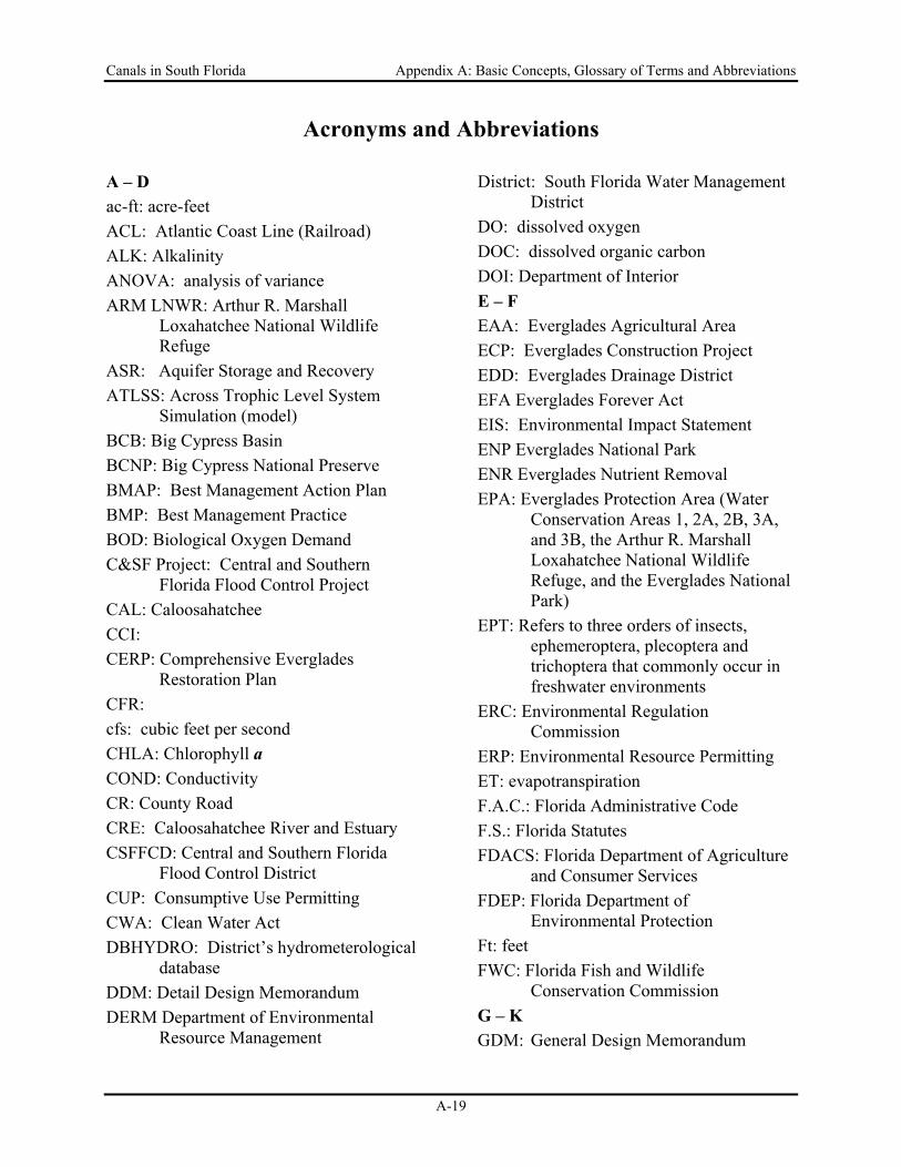
Acronyms and Abbreviations A – D ac-ft: acre-feet ACL: Atlantic Coast Line (Railroad) ALK: Alkalinity ANOVA: analysis of variance ARM LNWR: Arthur R. Marshall
Loxahatchee National Wildlife Refuge
ASR: Aquifer Storage and Recovery ATLSS: Across Trophic Level System
Simulation (model) BCB: Big Cypress Basin BCNP: Big Cypress National Preserve BMAP: Best Management Action Plan BMP: Best Management Practice BOD: Biological Oxygen Demand C&SF Project: Central and Southern
Florida Flood Control Project CAL: Caloosahatchee CCI: CERP: Comprehensive Everglades
Restoration Plan CFR: cfs: cubic feet per second CHLA: Chlorophyll a COND: Conductivity CR: County Road CRE: Caloosahatchee River and Estuary CSFFCD: Central and Southern Florida
Flood Control District CUP: Consumptive Use Permitting CWA: Clean Water Act DBHYDRO: District’s hydrometerological
database DDM: Detail Design Memorandum DERM Department of Environmental
Resource Management
District: South Florida Water Management District
DO: dissolved oxygen DOC: dissolved organic carbon DOI: Department of Interior E – F EAA: Everglades Agricultural Area ECP: Everglades Construction Project EDD: Everglades Drainage District EFA Everglades Forever Act EIS: Environmental Impact Statement ENP Everglades National Park ENR Everglades Nutrient Removal EPA: Everglades Protection Area (Water
Conservation Areas 1, 2A, 2B, 3A, and 3B, the Arthur R. Marshall Loxahatchee National Wildlife Refuge, and the Everglades National Park)
EPT: Refers to three orders of insects, ephemeroptera, plecoptera and trichoptera that commonly occur in freshwater environments
ERC: Environmental Regulation Commission
ERP: Environmental Resource Permitting ET: evapotranspiration F.A.C.: Florida Administrative Code F.S.: Florida Statutes FDACS: Florida Department of Agriculture
and Consumer Services FDEP: Florida Department of
Environmental Protection Ft: feet FWC: Florida Fish and Wildlife
Conservation Commission G – K GDM: General Design Memorandum
Canals in South Florida Appendix A: Basic Concepts, Glossary of Terms and Abbreviations
A-20
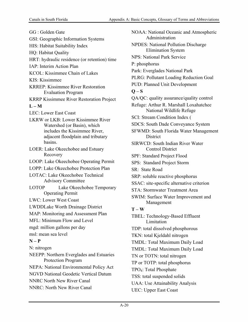
GG : Golden Gate GSI: Geographic Information Systems HIS: Habitat Suitability Index HQ: Habitat Quality HRT: hydraulic residence (or retention) time IAP: Interim Action Plan KCOL: Kissimmee Chain of Lakes KIS: Kissimmee KRREP: Kissimmee River Restoration
Evaluation Program KRRP Kissimmee River Restoration Project L – M LEC: Lower East Coast LKRW or LKB: Lower Kissimmee River
Watershed (or Basin), which includes the Kissimmee River, adjacent floodplain and tributary basins.
LOER: Lake Okeechobee and Estuary Recovery
LOOP: Lake Okeechobee Operating Permit LOPP: Lake Okeechobee Protection Plan LOTAC: Lake Okeechobee Technical
Advisory Committee LOTOP Lake Okeechobee Temporary
Operating Permit LWC: Lower West Coast LWDDLake Worth Drainage District MAP: Monitoring and Assessment Plan MFL: Minimum Flow and Level mgd: million gallons per day msl: mean sea level N – P N: nitrogen NEEPP: Northern Everglades and Estuaries
Protection Program NEPA: National Environmental Policy Act NGVD National Geodetic Vertical Datum NNRC North New River Canal NNRC: North New River Canal
NOAA: National Oceanic and Atmospheric Administration
NPDES: National Pollution Discharge Elimination System
NPS: National Park Service P: phosphorus Park: Everglades National Park PLRG: Pollutant Loading Reduction Goal PUD: Planned Unit Development Q – S QA/QC: quality assurance/quality control Refuge: Arthur R. Marshall Loxahatchee
National Wildlife Refuge SCI: Stream Condition Index ( SDCS: South Dade Conveyance System SFWMD: South Florida Water Management
District SIRWCD: South Indian River Water
Control District SPF: Standard Project Flood SPS: Standard Project Storm SR: State Road SRP: soluble reactive phosphorus SSAC: site-specific alternative criterion STA: Stormwater Treatment Area SWIM: Surface Water Improvement and
Management T – W TBEL: Technology-Based Effluent
Limitation TDP: total dissolved phosphorous TKN: total Kjeldahl nitrogen TMDL: Total Maximum Daily Load TMDL: Total Maximum Daily Load TN or TOTN: total nitrogen TP or TOTP: total phosphorus TPO4: Total Phosphate TSS: total suspended solids UAA: Use Attainability Analysis UEC: Upper East Coast
Canals in South Florida Appendix A: Basic Concepts, Glossary of Terms and Abbreviations
A-21
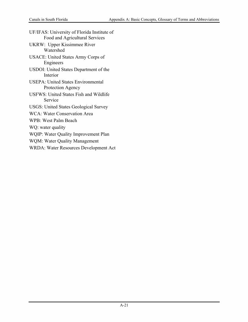
UF/IFAS: University of Florida Institute of Food and Agricultural Services
UKRW: Upper Kissimmee River Watershed
USACE: United States Army Corps of Engineers
USDOI: United States Department of the Interior
USEPA: United States Environmental Protection Agency
USFWS: United States Fish and Wildlife Service
USGS: United States Geological Survey WCA: Water Conservation Area WPB: West Palm Beach WQ: water quality WQIP: Water Quality Improvement Plan WQM: Water Quality Management WRDA: Water Resources Development Act
Canals in South Florida Appendix A: Basic Concepts, Glossary of Terms and Abbreviations
A-22
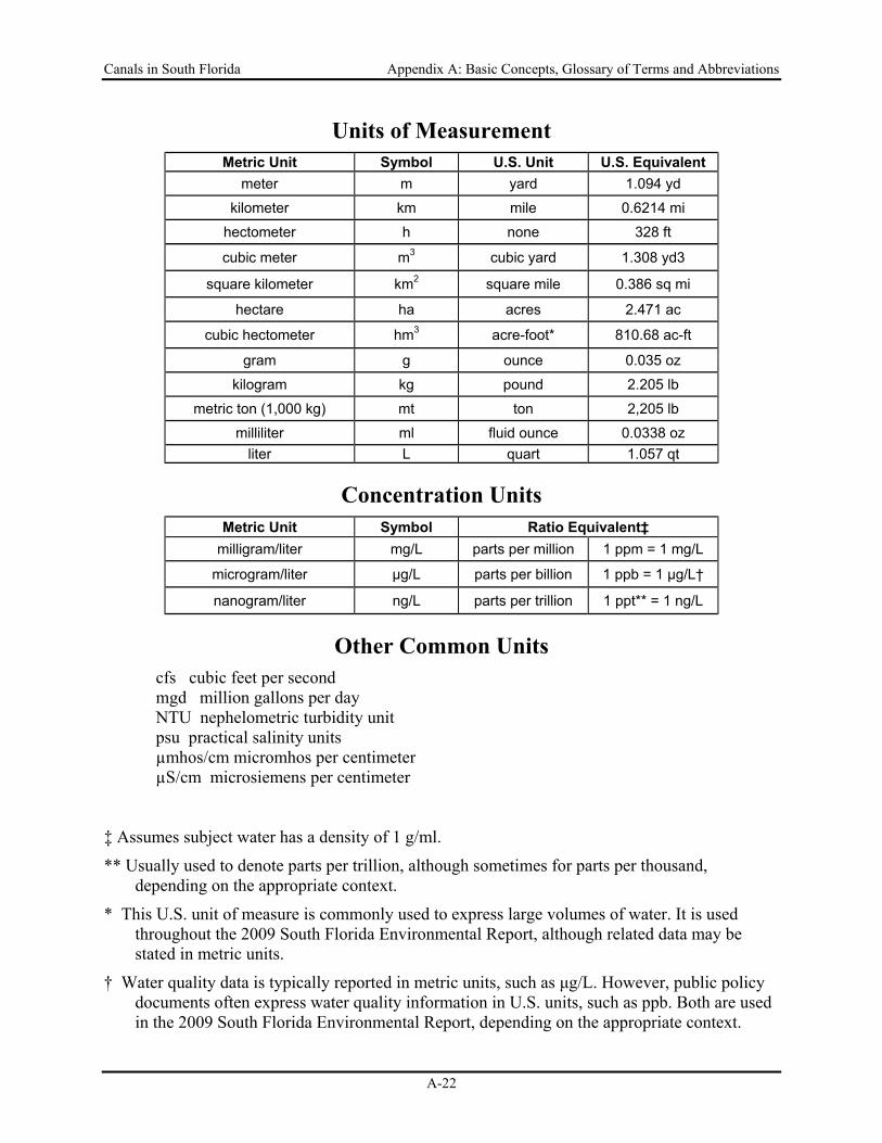
Units of Measurement Metric Unit Symbol U.S. Unit U.S. Equivalent
meter m yard 1.094 yd
kilometer km mile 0.6214 mi
hectometer h none 328 ft
cubic meter m3 cubic yard 1.308 yd3
square kilometer km2 square mile 0.386 sq mi
hectare ha acres 2.471 ac
cubic hectometer hm3 acre-foot* 810.68 ac-ft
gram g ounce 0.035 oz
kilogram kg pound 2.205 lb
metric ton (1,000 kg) mt ton 2,205 lb
milliliter ml fluid ounce 0.0338 oz liter L quart 1.057 qt
Concentration Units Metric Unit Symbol Ratio Equivalent‡
milligram/liter mg/L parts per million 1 ppm = 1 mg/L
microgram/liter μg/L parts per billion 1 ppb = 1 μg/L†
nanogram/liter ng/L parts per trillion 1 ppt** = 1 ng/L
Other Common Units cfs cubic feet per second mgd million gallons per day NTU nephelometric turbidity unit psu practical salinity units µmhos/cm micromhos per centimeter µS/cm microsiemens per centimeter
‡ Assumes subject water has a density of 1 g/ml.
** Usually used to denote parts per trillion, although sometimes for parts per thousand, depending on the appropriate context.
* This U.S. unit of measure is commonly used to express large volumes of water. It is used throughout the 2009 South Florida Environmental Report, although related data may be stated in metric units.
† Water quality data is typically reported in metric units, such as μg/L. However, public policy documents often express water quality information in U.S. units, such as ppb. Both are used in the 2009 South Florida Environmental Report, depending on the appropriate context.
Canals in South Florida Appendix B: Timelines
B-1
Canals in South Florida: A Technical Support Document
Appendix B
Timelines of Canal Construction in the Kissimmee Watershed and South of Lake Okeechobee
Canals in South Florida Appendix B: Timelines
B-2
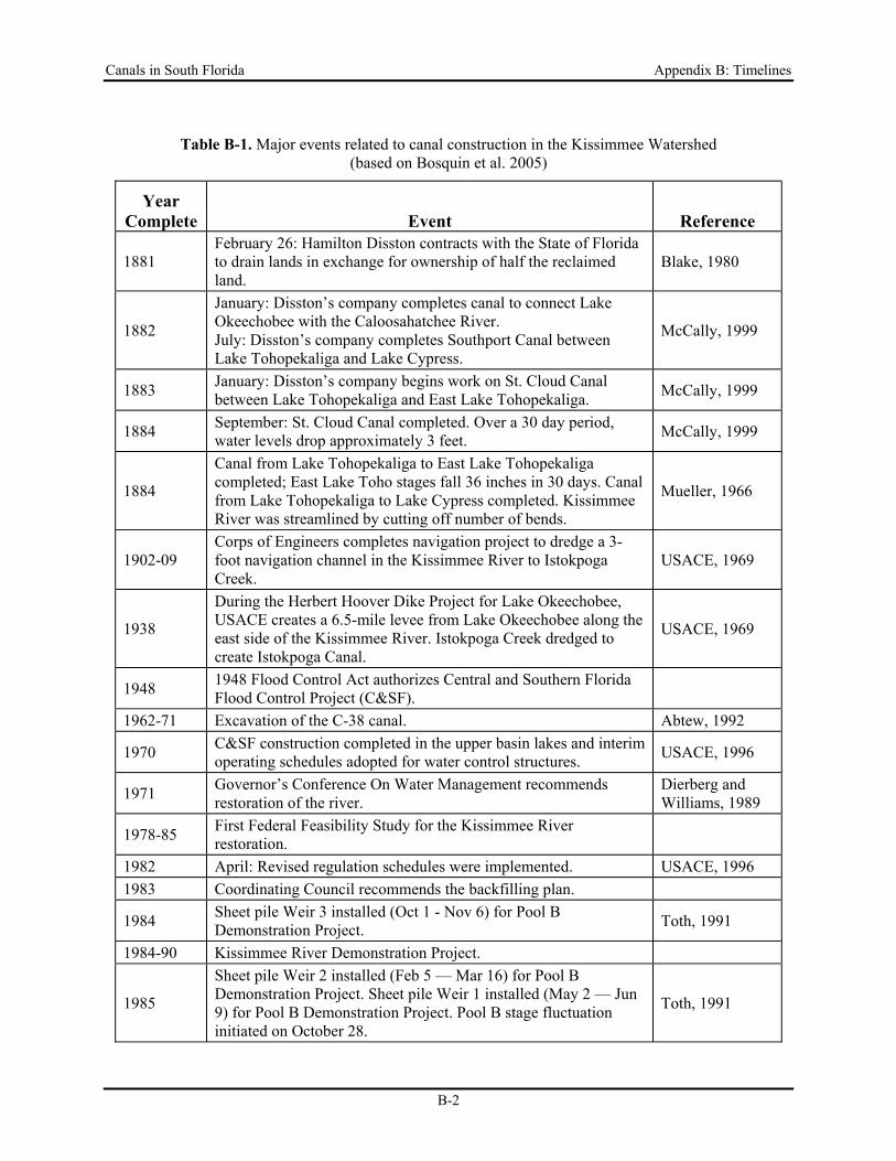
Table B-1. Major events related to canal construction in the Kissimmee Watershed (based on Bosquin et al. 2005)
Year Complete Event Reference
1881 February 26: Hamilton Disston contracts with the State of Florida to drain lands in exchange for ownership of half the reclaimed land.
Blake, 1980
1882
January: Disston’s company completes canal to connect Lake Okeechobee with the Caloosahatchee River. July: Disston’s company completes Southport Canal between Lake Tohopekaliga and Lake Cypress.
McCally, 1999
1883 January: Disston’s company begins work on St. Cloud Canal between Lake Tohopekaliga and East Lake Tohopekaliga. McCally, 1999
1884 September: St. Cloud Canal completed. Over a 30 day period, water levels drop approximately 3 feet. McCally, 1999
1884
Canal from Lake Tohopekaliga to East Lake Tohopekaliga completed; East Lake Toho stages fall 36 inches in 30 days. Canal from Lake Tohopekaliga to Lake Cypress completed. Kissimmee River was streamlined by cutting off number of bends.
Mueller, 1966
1902-09 Corps of Engineers completes navigation project to dredge a 3-foot navigation channel in the Kissimmee River to Istokpoga Creek.
USACE, 1969
1938
During the Herbert Hoover Dike Project for Lake Okeechobee, USACE creates a 6.5-mile levee from Lake Okeechobee along the east side of the Kissimmee River. Istokpoga Creek dredged to create Istokpoga Canal.
USACE, 1969
1948 1948 Flood Control Act authorizes Central and Southern Florida Flood Control Project (C&SF).
1962-71 Excavation of the C-38 canal. Abtew, 1992
1970 C&SF construction completed in the upper basin lakes and interim operating schedules adopted for water control structures. USACE, 1996
1971 Governor’s Conference On Water Management recommends restoration of the river.
Dierberg and Williams, 1989
1978-85 First Federal Feasibility Study for the Kissimmee River restoration.
1982 April: Revised regulation schedules were implemented. USACE, 1996 1983 Coordinating Council recommends the backfilling plan.
1984 Sheet pile Weir 3 installed (Oct 1 - Nov 6) for Pool B Demonstration Project. Toth, 1991
1984-90 Kissimmee River Demonstration Project.
1985
Sheet pile Weir 2 installed (Feb 5 — Mar 16) for Pool B Demonstration Project. Sheet pile Weir 1 installed (May 2 — Jun 9) for Pool B Demonstration Project. Pool B stage fluctuation initiated on October 28.
Toth, 1991
Canals in South Florida Appendix B: Timelines
B-3
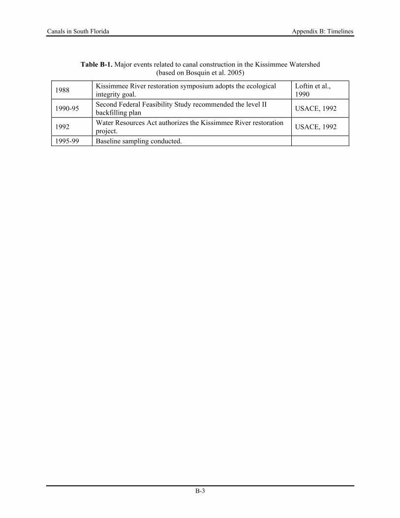
Table B-1. Major events related to canal construction in the Kissimmee Watershed (based on Bosquin et al. 2005)
1988 Kissimmee River restoration symposium adopts the ecological integrity goal.
Loftin et al., 1990
1990-95 Second Federal Feasibility Study recommended the level II backfilling plan USACE, 1992
1992 Water Resources Act authorizes the Kissimmee River restoration project. USACE, 1992
1995-99 Baseline sampling conducted.
Canals in South Florida Appendix B: Timelines
B-4
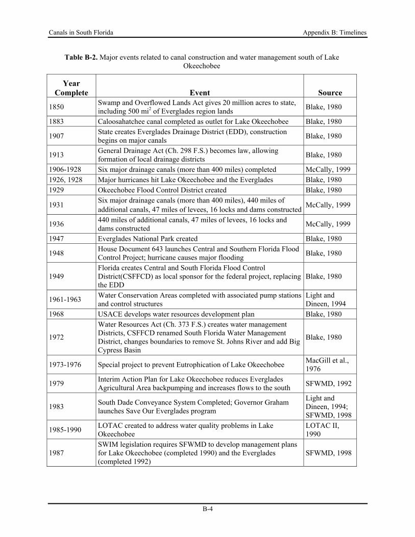
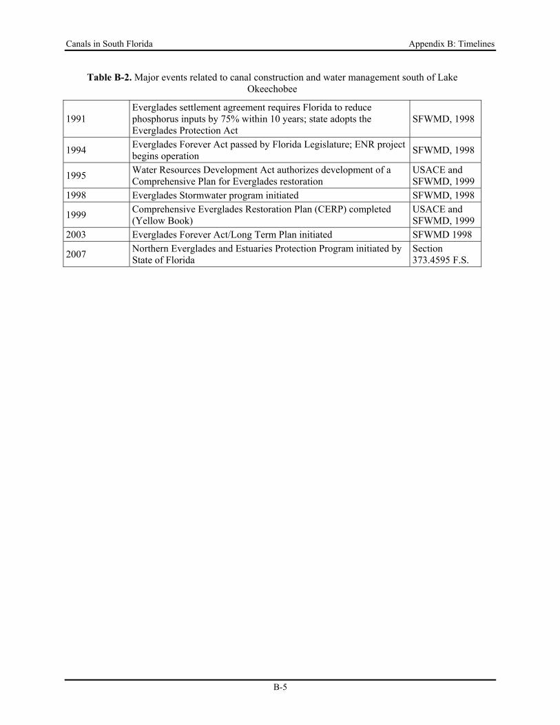
Table B-2. Major events related to canal construction and water management south of Lake Okeechobee
Year Complete Event Source
1850 Swamp and Overflowed Lands Act gives 20 million acres to state, including 500 mi2 of Everglades region lands Blake, 1980
1883 Caloosahatchee canal completed as outlet for Lake Okeechobee Blake, 1980
1907 State creates Everglades Drainage District (EDD), construction begins on major canals Blake, 1980
1913 General Drainage Act (Ch. 298 F.S.) becomes law, allowing formation of local drainage districts Blake, 1980
1906-1928 Six major drainage canals (more than 400 miles) completed McCally, 1999 1926, 1928 Major hurricanes hit Lake Okeechobee and the Everglades Blake, 1980 1929 Okeechobee Flood Control District created Blake, 1980
1931 Six major drainage canals (more than 400 miles), 440 miles of additional canals, 47 miles of levees, 16 locks and dams constructed McCally, 1999
1936 440 miles of additional canals, 47 miles of levees, 16 locks and dams constructed McCally, 1999
1947 Everglades National Park created Blake, 1980
1948 House Document 643 launches Central and Southern Florida Flood Control Project; hurricane causes major flooding Blake, 1980
1949 Florida creates Central and South Florida Flood Control District(CSFFCD) as local sponsor for the federal project, replacing the EDD
Blake, 1980
1961-1963 Water Conservation Areas completed with associated pump stations and control structures
Light and Dineen, 1994
1968 USACE develops water resources development plan Blake, 1980
1972
Water Resources Act (Ch. 373 F.S.) creates water management Districts, CSFFCD renamed South Florida Water Management District, changes boundaries to remove St. Johns River and add Big Cypress Basin
Blake, 1980
1973-1976 Special project to prevent Eutrophication of Lake Okeechobee MacGill et al., 1976
1979 Interim Action Plan for Lake Okeechobee reduces Everglades Agricultural Area backpumping and increases flows to the south SFWMD, 1992
1983 South Dade Conveyance System Completed; Governor Graham launches Save Our Everglades program
Light and Dineen, 1994; SFWMD, 1998
1985-1990 LOTAC created to address water quality problems in Lake Okeechobee
LOTAC II, 1990
1987 SWIM legislation requires SFWMD to develop management plans for Lake Okeechobee (completed 1990) and the Everglades (completed 1992)
SFWMD, 1998
Canals in South Florida Appendix B: Timelines
B-5
Table B-2. Major events related to canal construction and water management south of Lake Okeechobee
1991 Everglades settlement agreement requires Florida to reduce phosphorus inputs by 75% within 10 years; state adopts the Everglades Protection Act
SFWMD, 1998
1994 Everglades Forever Act passed by Florida Legislature; ENR project begins operation SFWMD, 1998
1995 Water Resources Development Act authorizes development of a Comprehensive Plan for Everglades restoration
USACE and SFWMD, 1999
1998 Everglades Stormwater program initiated SFWMD, 1998
1999 Comprehensive Everglades Restoration Plan (CERP) completed (Yellow Book)
USACE and SFWMD, 1999
2003 Everglades Forever Act/Long Term Plan initiated SFWMD 1998
2007 Northern Everglades and Estuaries Protection Program initiated by State of Florida
Section 373.4595 F.S.
Canals in South Florida Appendix B: Timelines
B-6
References Abtew, W. 1992. An atlas of the lower Kissimmee River and Lake Istokpoga surface water management basins.
Technical Memorandum. South Florida Water Management District, West Palm Beach, FL.
Blake, N.M. 1980. Land into Water - Water into Land. A history of water management in Florida. University Presses of Florida. Tallahassee, Florida. 344 pp.
Bosquin, S.G., D.H. Anderson, G.E. Williams and D.J. Colangelo 2005. Introduction to Baseline Studies of the Kissimmee River, Florida. Chapter 1, pp1-1 to 1-19. In: Bosquin, S.G., D.H. Anderson, G.E. Williams and D.J. Colangelo (eds.), 2005. Volume I Kissimmee River Restoration Studies: Establishing a Baseline: Pre-Restoration Studies of the Channelized Kissimmee River. Technical Publication No. ERA 432, South Florida Water Management District, West Palm Beach November 2005 487 pp.
Dierberg, F.E., and V.P. Williams. 1989. Lake management technique in Florida, USA: cost and water quality effects. Environmental Management 13:729-742.
Light, S.S. and J. W. Dineen, 1994. Water Control in the Everglades: A Historical Perspective. In: S. Davis and J. Ogden, 1994. Everglades: The Ecosystem and Its Restoration. St. Lucie Press, Delray Beach, FL pp 47-84.
Loftin, M. K., L. A. Toth, and J. T. B. Obeysekera. 1990. Proceedings of the Kissimmee River Restoration Symposium. South Florida Water Management District, West Palm Beach, Florida, USA.
LOTAC II. 1990. Lake Okeechobee Technical Advisory Council (LOTAC II). Final Report to the Governor of the State of Florida under Executive Order 88-152. Tallahassee, Florida. 64 pp. March.
MacGill, R.A., S.E. Gatewood, C. Hutchinson and D.D. Walker, 1976. Final report on the Special Project to Prevent Eutrophication of Lake Okeechobee. DSP-BCP-36-76. Florida Department of State Planning, Tallahassee, FL 341 pp.
McCally, D. 1999. The Everglades: An Environmental History. University Presses of Florida, Gainesville, FL
Mueller, E. A. 1966. Kissimmee steamboating. Tequesta 26:53-87.
South Florida Water Management District, 1992. Surface Water Improvement and Management Plan for the Everglades. Supporting Information Document. South Florida Water Management District, West Palm Beach, FL March, 1992.
South Florida Water Management District, 1998. ’98 Everglades Annual Report. South Florida Water Management District, West Palm Beach, FL 48 pp.
Toth, L. A. 1991. Environmental responses to the Kissimmee River Demonstration Project. Technical Publication 91-02. South Florida Water Management District, West Palm Beach, FL.
U.S. Army Corps of Engineers. 1969. Central and Southern Florida project for flood control and other purposes. Part II: Kissimmee River and related areas, Section 2 – General Design Memorandum. Supplement 5. U. S. Army Corps of Engineers, Jacksonville, FL.
U.S. Army Corps of Engineers. 1992. Central and Southern Florida, Kissimmee River Florida. Final Feasibility Report and environmental impact statement,: environmental restoration of the Kissimmee River , Florida a U. S. Army Corps of Engineers, Jacksonville, FL
U.S. Army Corps of Engineers. 1996. Kissimmee River headwaters revitalization project: integrated project modification report and supplement to the Final Environmental Impact Statement. U. S. Army Corps of Engineers. Jacksonville, FL.
U.S. Army Corps of Engineers and South Florida Water Management District. 1999. Central and Southern Florida Project Comprehensive Review Study, Final Integrated Feasibility Report and Programmatic Environmental Impact Statement, April 1999. South Florida Water Management District, West Palm Beach, FL and U.S. Army Corps of Engineers, Jacksonville, FL.
Canals in South Florida Appendix C: Primary Water Management Features
C-i
Canals in South Florida: A Technical Support Document
Appendix C
Description of SFWMD Primary Water Management Features
Contents Introduction 1 Upper Kissimmee River Watershed 1
Canals and Structures ............................................................................................................. 1 Operations .............................................................................................................................. 1 C-29, C-29A, C-29B, C-30 Canals (Lake Hart and Lake Myrtle Basins) ............................. 4 C-31 (East Lake Tohopekaliga and Lake Tohopekaliga Basins). ......................................... 5 C-32B, C-32C, C-32D, C-32F and C-32G, C-33 (Lake Myrtle and Alligator Lake Basins) 5 C-33, C-34 ,and C-35 ............................................................................................................. 4 C-36 and C-37 (Lake Hatchineha and Lake Kissimmee Basins). ......................................... 5
Lower Kissimmee River Watershed ........................................................................................... 6 Introduction ............................................................................................................................ 6 C-38 Canal ............................................................................................................................. 6
Other Basins that Discharge to C-38 ............................................................................... 11 Major Canals Downstream of Lake Istokpoga .................................................................... 11
C-41A Canal (Discharges to C-38). ................................................................................. 11 C-40 Canal (Discharges to Lake Okeechobee). ............................................................... 11 C-41 and C-39A Canals (Discharges to Lake Okeechobee). ........................................... 12 Other Basins that Discharge to C-40 and C-41 (L59W, L-60E, L-60W, L-61E) ............ 12
Basins that Flow Directly to Lake Okeechobee ................................................................... 12 Water Conservation Areas and Everglades National Park 13
Major Regional Canals and Structures ................................................................................ 13 West Palm Beach Canal (L-10/L-12 Borrow Canal) (WCA-1) ....................................... 13 Hillsboro Canal and L-39 (WCA-1), WCA-2A ............................................................... 13 North New River Canal and L-38 (WCA-2A and WCA-3A) ......................................... 24 Miami Canal (WCA-3A and WCA-3B ............................................................................ 13
Peripheral Canals ................................................................................................................. 23 WCA-1 ............................................................................................................................. 23 WCA-2 ............................................................................................................................. 23 WCA-3 and ENP.............................................................................................................. 23
Everglades Agricultural Area 24 Major Project Canals ........................................................................................................... 24
L-8 Canal ......................................................................................................................... 24 West Palm Beach Canal (L-10/L-12 borrow canal) ........................................................ 25 Hillsboro Canal ................................................................................................................ 25 North New River Canal ................................................................................................... 30 Miami Canal..................................................................................................................... 26 Other Project Canals ........................................................................................................ 26
Canals in South Florida Appendix C: Primary Water Management Features
C-ii
Upper East Coast Watershed .................................................................................................... 31 Primary Canals that Discharge to Coastal Waters ............................................................... 31
C-23 Canal ...................................................................................................................... 31 C-44 (St. Lucie Canal) and C-44A .................................................................................. 35 C-25 Canal ....................................................................................................................... 35 C-24 and C-23A ............................................................................................................... 35
Basins that Discharge to Lake Okeechobee ......................................................................... 36 S-135 basin....................................................................................................................... 36 C-59 Basin ....................................................................................................................... 36
Southeast Coast – Palm Beach, Broward and Miami-Dade Counties ...................................... 37 Major Regional Canals ........................................................................................................ 37
West Palm Beach Canal (C-51) ....................................................................................... 37 Hillsboro Canal ................................................................................................................ 41 North New River Canal ................................................................................................... 41 Miami Canal (C-6) ........................................................................................................... 42
Coastal Basin Canals. .......................................................................................................... 45 Palm Beach County.......................................................................................................... 45 Broward County ............................................................................................................... 46 Miami-Dade County ........................................................................................................ 47 Other Coastal Basins ........................................................................................................ 53 South Dade Conveyance System ..................................................................................... 54
Lower West Coast Watersheds ................................................................................................. 58 Caloosahatchee River .......................................................................................................... 58
Features of the current system ......................................................................................... 58 Collier County ...................................................................................................................... 60
Surface Hydrology and Hydraulic Systems ..................................................................... 60 References ................................................................................................................................. 71
Canals in South Florida Appendix C: Primary Water Management Features
C-iii
Figures
Figure C-1. A. Locations of major sub-basins, rivers, streams lakes, canals, and structures in the upper Kissimmee River watershed. B. Natural soil landscape positions in the upper Kissimmee River watershed. ........................................................................................ 2
Figure C-2. A. Locations of major sub-basins, rivers, streams lakes, canals, and structures in the lower Kissimmee River watershed. B. Natural soil landscape positions in the lowerKissimmee River watershed. ............................................................................... 8
Figure C-3. WCA and Everglades National Park Drainage Basins and water management features ....................................................................................................................... 14
Figure C-4. A. Locations of major sub-basins, canals, and structures in the EAA watershed. B. Natural soil landscape positions in the EAA watershed. ............................................ 27
Figure C-5. Sub-Basins and SFWMD project Facilities and Distribution of Hydric and Upland Soils in Martin and St. Lucie County Sub-basins ....................................................... 32
Figure C-6. a) SFWMD Canals and structures, and b) natural landscape soil positions in coastal sub-basins of Miami-Dade, Broward and Palm Beach counties (based on Zahina et al. 2001) ........................................................................................................................... 38
Figure C-7. The South Dade Conveyance System (Source: Light and Dineen, 1994) ............. 55 Figure C-8. Major Features of the Caloosahatchee River Watershed ...................................... 59 Figure C-9. Distribution of Hydric and Upland Soils in the Caloosahatchee Basin ................ 59 Figure C-10. Major Drainage Basins and Water Management Features within the Big Cypress
Basin. .......................................................................................................................... 61 Figure C-11. Water Management Basins and Distribution of Hydric and Upland Soils in Collier
County ........................................................................................................................ 62
List of Tables
Table C-1. Canals in the Upper Kissimmee River Watershed and associated Design information ................................................................................................................... 3
Table C-2. Control Structures in the Upper Kissimmee River Watershed ................................. 4 Table C-3. Summary of Design Features for Primary Canals in the LKRW and Lake Istokpoga
Basins ........................................................................................................................... 7 Table C-4. LKRW Design Criteria for Structures on C-38. ...................................................... 9 Table C-5. Structure Design Criteria for C-41A, S-127, -129, L-59E, L-59W, L-60E, L-60W, L-
61E and L-61W Basins in the LKRW. ....................................................................... 10 Table C-6. Design Information for Canals in the WCA/ENP Watershed ............................... 15 Table C-7. Water Conservation Area 1 Structures - Design Criteria. ...................................... 16 Table C-8. Water Conservation Area 2A Structures - Design Criteria ..................................... 17 Table C-9. Water Conservation Area 2B Structures-Design Criteria ...................................... 18 Table C-10. Water Conservation Area 3A Structures - Design Criteria ................................... 19
Canals in South Florida Appendix C: Primary Water Management Features
C-iv
Table C-11. Water Conservation Area 3B Structures - Design Criteria ................................... 21 Table C-12. Everglades National Park Basin Structures - Design Criteria .............................. 22 Table C-13. Canals in the EAA Watershed and Associated Design Information ................... 28 Table C-14. EAA Basin Structures – Design Criteria .............................................................. 29 Table C-15. Canals in the Upper East Coast Watershed and Associated Design Information 33 Table C-16 Martin and St. Lucie Counties Basin Structures – Design Criteria ...................... 34 Table C-17. Canals in The Eastern Watersheds of Palm Beach, Broward and Miami-Dade
Counties and Associated Design Information ............................................................ 39 Table C-18. Palm Beach County Canal Basin Structures – Design Criteria ........................... 40 Table C-18 (cont.). Palm Beach County Canal Basin Structures – Design Criteria ................. 41 Table C-19. Broward County Canal Basin Structures – Design Criteria ................................ 43 Table C-19. (cont.) Broward County Canal Basin Structures – Design Criteria ..................... 44 Table C-20. Miami-Dade County Canal Basin Structures – Design Criteria .......................... 49 Table C-20 (cont.) Miami-Dade County Canal Basin Structures – Design Criteria ............... 50 Table C-20 (cont.) Miami-Dade County Canal Basin Structures – Design Criteria ............... 51 Table C-20 (cont.) Miami-Dade County Canal Basin Structures – Design Criteria ............... 52 Table C-21. Stages and Flows in the South Dade Conveyance System .................................. 56 Table C- 22. BCB-Operated Water Control Structures in the Big Cypress Basin .................. 65 Table C-23. Hydraulic Performance of Canal segments within the Big Cypress Basin .......... 67
Canals in South Florida Appendix C: Primary Water Management Features
C-1
APPENDIX C.
DESCRIPTION OF SFWMD PRIMARY WATER MANAGEMENT FEATURES
Introduction The following sections provide more detailed descriptions of the primary canals, structures, and operations within the District. For convenience in organizing the information and descriptions, the District is divided into seven study areas, corresponding approximately to the areas used in the water quality analysis (see the Water Quality and Sediment section of the main report and Appendix G). Information about canals and structures within each of these areas has been compiled to characterize the unique physical features of the canals and their watershed, including existing physical conditions and water control structures that affect their design, structure, and operation. References at the end of this appendix represent a partial list of historical reports, primarily from the SFWMD and USACE, associated with design and construction of major features of the Central and Southern Florida Flood Control Project (C&SF Project).
Upper Kissimmee River Watershed
Canals and Structures The primary canal system in the Upper Kissimmee River watershed (UKRW) consists of a network of 15 canals that range from 0.2 to 4.5 miles in length with a total length of 31.1 miles (Figure C-1). The canals generally connect from one lake to another to form a linked chain. The drainage area for each canal ranges from 21 to 60 square miles. Water levels and/or flows in eight of these canals are controlled by water management structures, such as culverts and spillways. Two of the structures (S-61 and S-65) have navigational locks. Water levels in seven of the eight canals with water control structures are also constrained by regulation schedules in one or both of the connected lakes (Table C-1).
Operations A list of structures and their design features within the UKRW is provided in Table C-2. Flood operation protocols and criteria are followed if water-surface elevations are above prescribed levels and low-water operations are followed if water surfaces are below prescribed elevations. Operations also depend on hydraulic and structural limitations of the structures. The gate openings are limited in accordance with the "Maximum Allowable Gate Opening Curve." To prevent damage from high velocities, gates generally have to be opened gradually to allow tailwater stages to rise before large discharges are released. Table C-2 also includes summary data (water levels and discharges) for historic flood events.
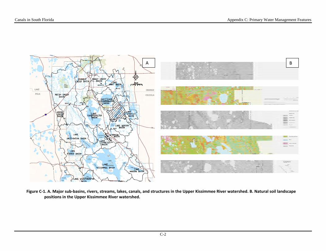
Canals in South Florida Appendix C: Primary Water Management Features
C-2
Figure C‐1. A. Major sub‐basins, rivers, streams, lakes, canals, and structures in the Upper Kissimmee River watershed. B. Natural soil landscape positions in the Upper Kissimmee River watershed.
A B
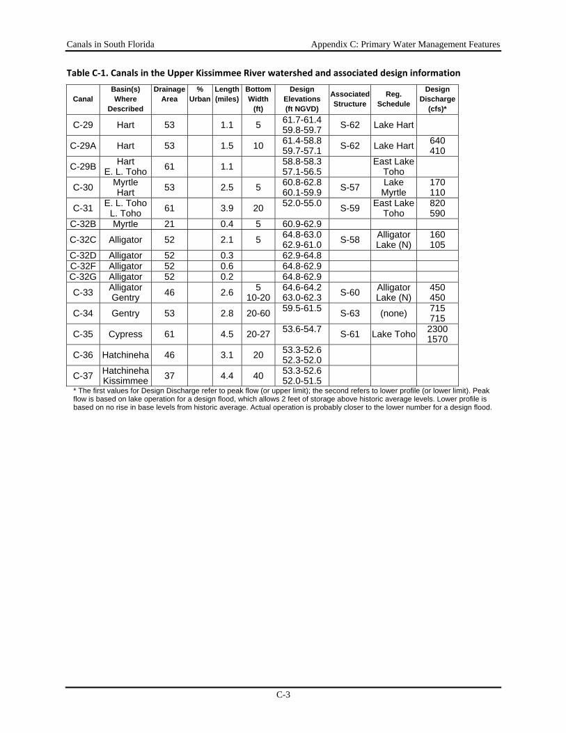
Canals in South Florida Appendix C: Primary Water Management Features
C-3
Table C‐1. Canals in the Upper Kissimmee River watershed and associated design information
Canal Basin(s) Where
Described
Drainage Area
% Urban
Length(miles)
BottomWidth
(ft)
Design Elevations (ft NGVD)
Associated Structure
Reg. Schedule
Design Discharge
(cfs)*
C-29 Hart 53 1.1 5 61.7-61.459.8-59.7 S-62 Lake Hart
C-29A Hart 53 1.5 10 61.4-58.859.7-57.1 S-62 Lake Hart 640
410
C-29B Hart E. L. Toho 61 1.1 58.8-58.3
57.1-56.5 East Lake Toho
C-30 Myrtle Hart 53 2.5 5 60.8-62.8
60.1-59.9 S-57 Lake Myrtle
170 110
C-31 E. L. Toho L. Toho 61 3.9 20 52.0-55.0 S-59 East Lake
Toho 820 590
C-32B Myrtle 21 0.4 5 60.9-62.9
C-32C Alligator 52 2.1 5 64.8-63.062.9-61.0 S-58 Alligator
Lake (N) 160 105
C-32D Alligator 52 0.3 62.9-64.8 C-32F Alligator 52 0.6 64.8-62.9 C-32G Alligator 52 0.2 64.8-62.9
C-33 Alligator Gentry 46 2.6 5
10-2064.6-64.263.0-62.3 S-60 Alligator
Lake (N) 450 450
C-34 Gentry 53 2.8 20-60 59.5-61.5 S-63 (none) 715 715
C-35 Cypress 61 4.5 20-27 53.6-54.7 S-61 Lake Toho 2300 1570
C-36 Hatchineha 46 3.1 20 53.3-52.652.3-52.0
C-37 Hatchineha Kissimmee 37 4.4 40 53.3-52.6
52.0-51.5 * The first values for Design Discharge refer to peak flow (or upper limit); the second refers to lower profile (or lower limit). Peak flow is based on lake operation for a design flood, which allows 2 feet of storage above historic average levels. Lower profile is based on no rise in base levels from historic average. Actual operation is probably closer to the lower number for a design flood.
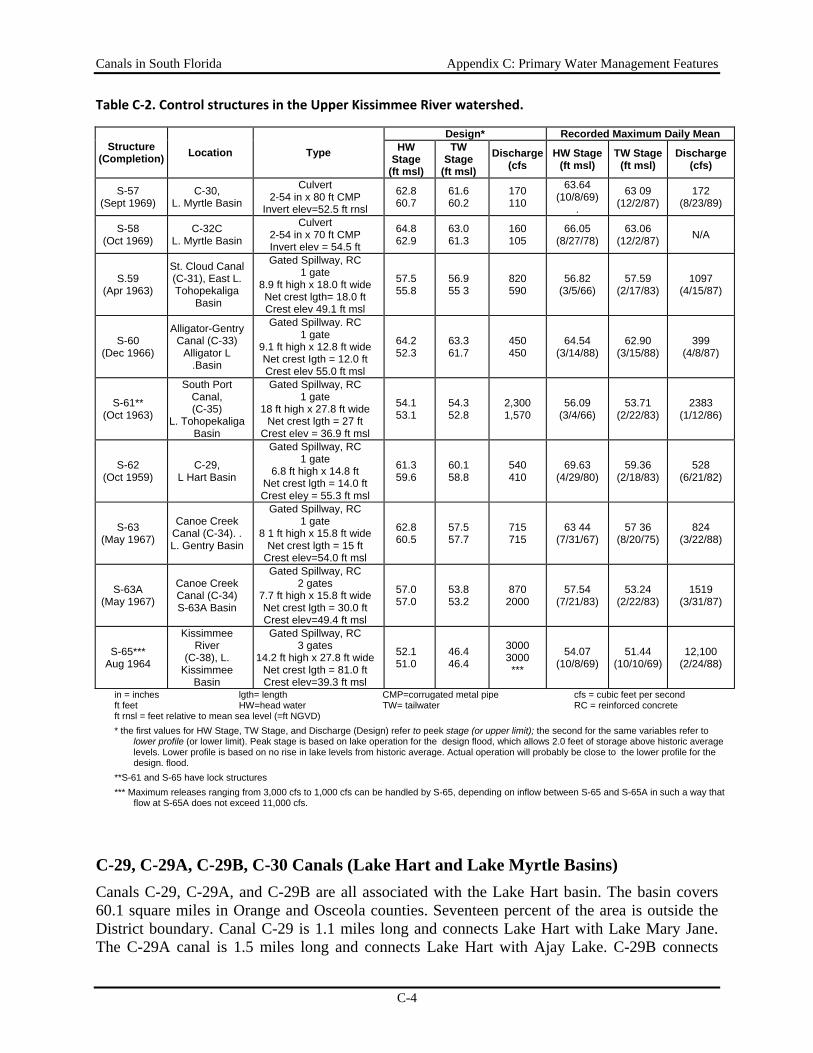
Canals in South Florida Appendix C: Primary Water Management Features
C-4
Table C‐2. Control structures in the Upper Kissimmee River watershed.
Structure (Completion) Location Type
Design* Recorded Maximum Daily Mean HW
Stage (ft msl)
TW Stage
(ft msl) Discharge
(cfs HW Stage
(ft msl) TW Stage
(ft msl) Discharge
(cfs)
S-57 (Sept 1969)
C-30, L. Myrtle Basin
Culvert 2-54 in x 80 ft CMP
Invert elev=52.5 ft rnsl
62.8 60.7
61.6 60.2
170 110
63.64 (10/8/69)
.
63 09 (12/2/87)
172 (8/23/89)
S-58 (Oct 1969)
C-32C L. Myrtle Basin
Culvert 2-54 in x 70 ft CMP Invert elev = 54.5 ft
64.8 62.9
63.0 61.3
160 105
66.05 (8/27/78)
63.06 (12/2/87) N/A
S.59 (Apr 1963)
St. Cloud Canal(C-31), East L. Tohopekaliga
Basin
Gated Spillway, RC 1 gate
8.9 ft high x 18.0 ft wide Net crest lgth= 18.0 ft Crest elev 49.1 ft msl
57.5 55.8
56.9 55 3
820 590
56.82 (3/5/66)
57.59 (2/17/83)
1097 (4/15/87)
S-60 (Dec 1966)
Alligator-Gentry Canal (C-33)
Alligator L .Basin
Gated Spillway. RC 1 gate
9.1 ft high x 12.8 ft wide Net crest Igth = 12.0 ft Crest elev 55.0 ft msl
64.2 52.3
63.3 61.7
450 450
64.54 (3/14/88)
62.90 (3/15/88)
399 (4/8/87)
S-61** (Oct 1963)
South Port Canal, (C-35)
L. Tohopekaliga Basin
Gated Spillway, RC 1 gate
18 ft high x 27.8 ft wide Net crest lgth = 27 ft
Crest elev = 36.9 ft msl
54.1 53.1
54.3 52.8
2,300 1,570
56.09 (3/4/66)
53.71 (2/22/83)
2383 (1/12/86)
S-62 (Oct 1959)
C-29, L Hart Basin
Gated Spillway, RC 1 gate
6.8 ft high x 14.8 ft Net crest lgth = 14.0 ft Crest eley = 55.3 ft msl
61.3 59.6
60.1 58.8
540 410
69.63 (4/29/80)
59.36 (2/18/83)
528 (6/21/82)
S-63 (May 1967)
Canoe Creek Canal (C-34). . L. Gentry Basin
Gated Spillway, RC 1 gate
8 1 ft high x 15.8 ft wide Net crest lgth = 15 ft
Crest elev=54.0 ft msl
62.8 60.5
57.5 57.7
715 715
63 44 (7/31/67)
57 36 (8/20/75)
824 (3/22/88)
S-63A (May 1967)
Canoe Creek Canal (C-34) S-63A Basin
Gated Spillway, RC 2 gates
7.7 ft high x 15.8 ft wide Net crest lgth = 30.0 ft Crest elev=49.4 ft msl
57.0 57.0
53.8 53.2
870 2000
57.54 (7/21/83)
53.24 (2/22/83)
1519 (3/31/87)
S-65*** Aug 1964
Kissimmee River
(C-38), L. Kissimmee
Basin
Gated Spillway, RC 3 gates
14.2 ft high x 27.8 ft wide Net crest lgth = 81.0 ft Crest elev=39.3 ft msl
52.1 51.0
46.4 46.4
3000 3000 ***
54.07 (10/8/69)
51.44 (10/10/69)
12,100 (2/24/88)
in = inches lgth= length CMP=corrugated metal pipe cfs = cubic feet per second ft feet HW=head water TW= tailwater RC = reinforced concrete ft rnsl = feet relative to mean sea level (=ft NGVD) * the first values for HW Stage, TW Stage, and Discharge (Design) refer to peek stage (or upper limit); the second for the same variables refer to
lower profile (or lower limit). Peak stage is based on lake operation for the design flood, which allows 2.0 feet of storage above historic average levels. Lower profile is based on no rise in lake levels from historic average. Actual operation will probably be close to the lower profile for the design. flood.
**S-61 and S-65 have lock structures *** Maximum releases ranging from 3,000 cfs to 1,000 cfs can be handled by S-65, depending on inflow between S-65 and S-65A in such a way that
flow at S-65A does not exceed 11,000 cfs.
C-29, C-29A, C-29B, C-30 Canals (Lake Hart and Lake Myrtle Basins) Canals C-29, C-29A, and C-29B are all associated with the Lake Hart basin. The basin covers 60.1 square miles in Orange and Osceola counties. Seventeen percent of the area is outside the District boundary. Canal C-29 is 1.1 miles long and connects Lake Hart with Lake Mary Jane. The C-29A canal is 1.5 miles long and connects Lake Hart with Ajay Lake. C-29B connects
Canals in South Florida Appendix C: Primary Water Management Features
C-5
Ajay Lake to East Lake Tohopekaliga (Fells Cove). The Lake Myrtle basin has an area of 47.5 square miles. Lake Myrtle discharges into Lake Mary Jane (Lake Hart basin) by means of C-30, which is 2.5 miles long.
C-31 (East Lake Tohopekaliga and Lake Tohopekaliga Basins) The East Lake Tohopekaliga basin has an area of 50.8 square miles and the Lake Tohopekaliga basin has an area of 131.4 square miles located within Orange and Osceola counties. Boggy Creek discharges into the northwestern shore of East Lake Tohopekaliga and C-29B discharges to the lake at Fells Cove. Water levels in East Lake Tohopekaliga are regulated by S-59, located in the St. Cloud Canal (C-31). The C-31 canal is 3.9 miles long. The two major sources of inflow to Lake Tohopekaliga are Shingle Creek and C-31. Discharges from Lake Tohopekaliga are conveyed via South Port Canal (C-35) to Lake Cypress through S-61.
C-32B, C-32C, C-32D, C-32F, C-32G and C-33 (Lake Myrtle and Alligator Lake Basins) The Alligator Lake basin has an area of 46.8 square miles in Osceola County. The primary canal system in this basin connects Lake Myrtle, Lake Joel, Trout Lake, Coon Lake, Lake Lizzie, and Alligator Lake by a series of short channels. This basin contains five primary canals and two control structures. Alligator Lake receives surface inflow from several tributary lakes and from the Lake Lizzie area through the C-32G canal, which is about 0.2 miles long. Outflow from Alligator Lake can go either north or south. Water flows north to Lake Lizzie through C-32F, which is 0.6 miles long and connects Lake Lizzie to Coon Lake. C-32D connects Coon Lake to Trout Lake and is 0.3 miles long. The C-32C canal is 2.1 miles long and connects Trout Lake to Lake Joel. C-32B connects Lake Joel to Lake Myrtle and is 0.4 miles long.
C-33, C-34 and C-35 Because of the limited capacity of the lakes north of Alligator Lake, discharges generally flow south to Lake Gentry through the Alligator-Gentry Canal (C-33) and S-60. C-33 is 2.6 miles long. Water flows from Lake Gentry for 5.7 miles through Canoe Creek Canal (C-34) to Lake Cypress through S-63. The Lake Cypress basin is located in Osceola and Polk counties. Water also flows into Lake Cypress from the South Port Canal (C-35) and Reedy Creek. C-35 is 4.5 miles long and connects Lake Tohopekaliga with Lake Cypress.
C-36 and C-37 (Lake Hatchineha and Lake Kissimmee Basins) The Lake Hatchineha basin has an area of 128.5 square miles and the Lake Kissimmee basin has an area of 269.1 square miles in Osceola and Polk counties. Water is conveyed from Lake Marion to Lake Hatchineha by Lake Marion Creek and from Lake Cypress by the Cypress-Hatchineha Canal (C-36). C-36 is 3.1 miles long. C-37 is 4.4 miles long and connects Lake Hatchineha to Lake Kissimmee. The S-65 structure at the southern end of Lake Kissimmee is the discharge outlet for surface flows leaving the entire UKRW.
Canals in South Florida Appendix C: Primary Water Management Features
C-6
Lower Kissimmee River Watershed
Introduction The major features of the primary canal system in the Lower Kissimmee River watershed (LKRW) are the channelized portion of the Kissimmee River and the canal system located south of Lake Istokpoga (Figure C-2). Major features of thecCanals are summarized in Table C-3. The water control structures of the LKRW are described in Tables C-4 and C-5.
C-38 Canal The Kissimmee River was originally channelized in 1880 by Hamilton Disston to facilitate navigation between Lake Kissimmee and Lake Okeechobee and provide drainage and flood protection for lands in the floodplain and upstream watersheds. The canal was widened and deepened over the years, but the major improvements occurred between 1966 and 1971 when the USACE constructed the C-38 canal. The old canal was deepened and widened, further straightened, and the canal and floodplain were divided into a series of five “pools.” The pools were separated by construction of six water control structures (S-65, S-65A. S-65B, S-65C, S-65D and S-65E) and associated access roads and tieback levees across the floodplain. The naturally sloping surface of the river was thus replaced with five flat pools in a stairstep manner. The water level within each pool remains level; therefore, floodplain lands (formerly wetlands) in the northern end of each pool are over-drained and now serve as dry pastures or croplands.
The southern end of each pool is excessively flooded. Areas that were formerly marshes and wet prairies are now ponds and sloughs. The structures at the ends of each pool include culverts, a spillway, and navigational locks to control water flow and boat traffic. The water level in the canal on the upstream side of each structure was four to six feet higher than the water level on the downstream side. Overall, from the upstream beginning of C-38 at S-65 in Lake Kissimmee (elevation 52 feet NGVD) to the downstream end below S-65E (elevation 17 feet NGVD), the water level dropped by about 35 feet while passing through these six control structures. Design features of the water control structures on the C-38 canal are listed in Table C-3. The C-38 canal watershed has been divided into five sub-basins, corresponding to the drainage area within each of the five pools (pools A-E). For example the segment of the canal between S-65 and S-65A has a channel length of 10.6 miles, width of 90 feet and, depth of 18 to 24 feet. This segment is designated as C-38 Canal Pool A and the associated land area that drains into it is the S-65A sub-basin.
In the past, the outlet for Lake Istokpoga had been the Istokpoga Canal which flows to C-38 in the S-65C basin. Since the construction of S-68, the primary outlet for Lake Istokpoga has been the C-41A canal. The sheet pile weir structure G-85 on the Istokpoga Canal maintains lake stage. If S-68 is over capacity, a minimum of 800 cfs can be released through the Istokpoga Canal to Pool C.
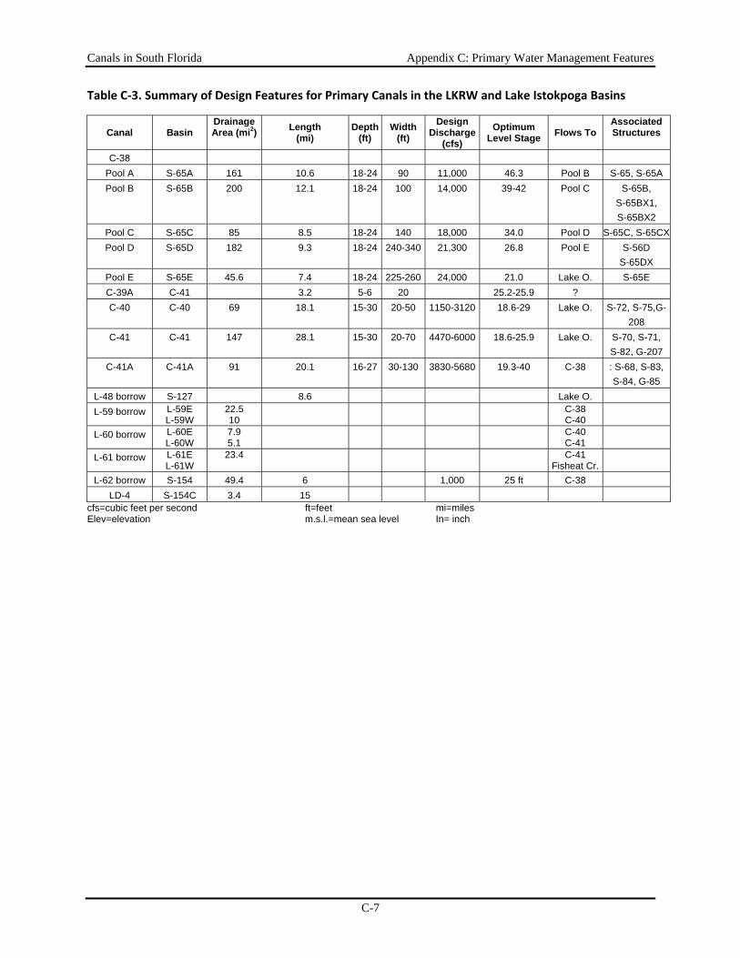
Canals in South Florida Appendix C: Primary Water Management Features
C-7
Table C‐3. Summary of Design Features for Primary Canals in the LKRW and Lake Istokpoga Basins
Canal Basin Drainage Area (mi2) Length
(mi) Depth
(ft) Width
(ft) Design
Discharge(cfs)
Optimum Level Stage Flows To
Associated Structures
C-38 Pool A S-65A 161 10.6 18-24 90 11,000 46.3 Pool B S-65, S-65A Pool B S-65B 200 12.1 18-24 100 14,000 39-42 Pool C S-65B,
S-65BX1, S-65BX2
Pool C S-65C 85 8.5 18-24 140 18,000 34.0 Pool D S-65C, S-65CXPool D S-65D 182 9.3 18-24 240-340 21,300 26.8 Pool E S-56D
S-65DX Pool E S-65E 45.6 7.4 18-24 225-260 24,000 21.0 Lake O. S-65E C-39A C-41 3.2 5-6 20 25.2-25.9 ? C-40 C-40 69 18.1 15-30 20-50 1150-3120 18.6-29 Lake O. S-72, S-75,G-
208 C-41 C-41 147 28.1 15-30 20-70 4470-6000 18.6-25.9 Lake O. S-70, S-71,
S-82, G-207 C-41A C-41A 91 20.1 16-27 30-130 3830-5680 19.3-40 C-38 : S-68, S-83,
S-84, G-85 L-48 borrow S-127 8.6 Lake O. L-59 borrow L-59E
L-59W 22.5 10
C-38 C-40
L-60 borrow L-60E L-60W
7.9 5.1
C-40 C-41
L-61 borrow L-61E L-61W
23.4 C-41 Fisheat Cr.
L-62 borrow S-154 49.4 6 1,000 25 ft C-38 LD-4 S-154C 3.4 15
cfs=cubic feet per second ft=feet mi=miles Elev=elevation m.s.l.=mean sea level In= inch
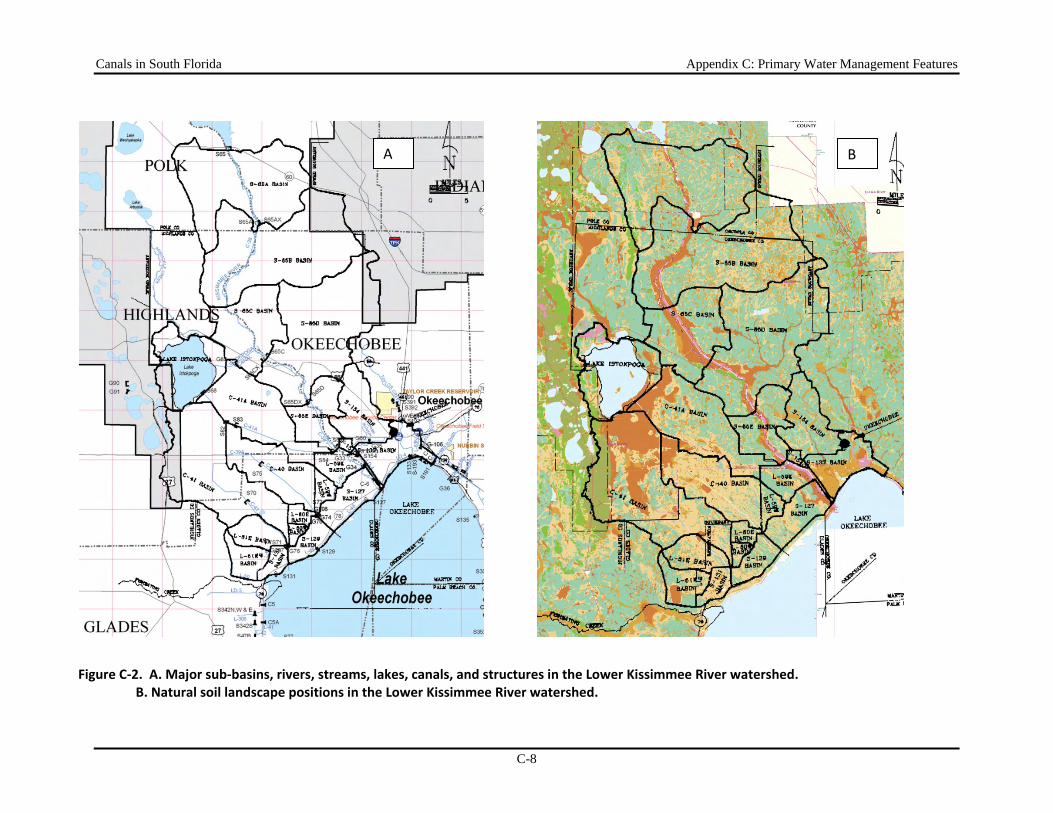
Canals in South Florida Appendix C: Primary Water Management Features
C-8
Figure C‐2. A. Major sub‐basins, rivers, streams, lakes, canals, and structures in the Lower Kissimmee River watershed. B. Natural soil landscape positions in the Lower Kissimmee River watershed.
A B
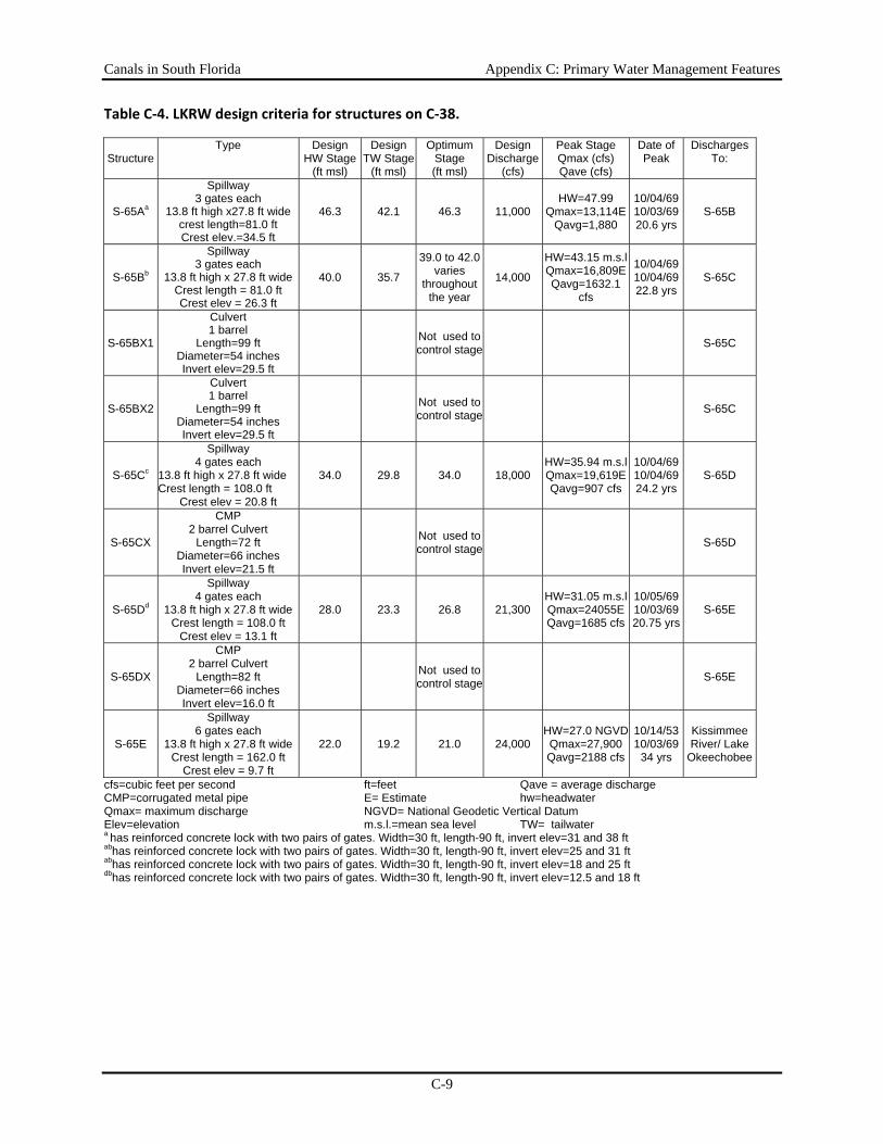
Canals in South Florida Appendix C: Primary Water Management Features
C-9
Table C‐4. LKRW design criteria for structures on C‐38.
Structure Type Design
HW Stage (ft msl)
Design TW Stage
(ft msl)
Optimum Stage (ft msl)
Design Discharge
(cfs)
Peak Stage Qmax (cfs) Qave (cfs)
Date of Peak
Discharges To:
S-65Aa
Spillway 3 gates each
13.8 ft high x27.8 ft wide crest length=81.0 ft Crest elev.=34.5 ft
46.3 42.1 46.3 11,000 HW=47.99
Qmax=13,114E Qavg=1,880
10/04/69 10/03/69 20.6 yrs
S-65B
S-65Bb
Spillway 3 gates each
13.8 ft high x 27.8 ft wide Crest length = 81.0 ft Crest elev = 26.3 ft
40.0 35.7
39.0 to 42.0varies
throughoutthe year
14,000
HW=43.15 m.s.l Qmax=16,809E Qavg=1632.1
cfs
10/04/69 10/04/69 22.8 yrs
S-65C
S-65BX1
Culvert 1 barrel
Length=99 ft Diameter=54 inches Invert elev=29.5 ft
Not used tocontrol stage S-65C
S-65BX2
Culvert 1 barrel
Length=99 ft Diameter=54 inches Invert elev=29.5 ft
Not used tocontrol stage S-65C
S-65Cc
Spillway 4 gates each
13.8 ft high x 27.8 ft wide Crest length = 108.0 ft
Crest elev = 20.8 ft
34.0 29.8 34.0 18,000 HW=35.94 m.s.l Qmax=19,619E Qavg=907 cfs
10/04/69 10/04/69 24.2 yrs
S-65D
S-65CX
CMP 2 barrel Culvert
Length=72 ft Diameter=66 inches Invert elev=21.5 ft
Not used tocontrol stage S-65D
S-65Dd
Spillway 4 gates each
13.8 ft high x 27.8 ft wide Crest length = 108.0 ft
Crest elev = 13.1 ft
28.0 23.3 26.8 21,300 HW=31.05 m.s.l Qmax=24055E Qavg=1685 cfs
10/05/69 10/03/69 20.75 yrs
S-65E
S-65DX
CMP 2 barrel Culvert
Length=82 ft Diameter=66 inches Invert elev=16.0 ft
Not used tocontrol stage S-65E
S-65E
Spillway 6 gates each
13.8 ft high x 27.8 ft wide Crest length = 162.0 ft
Crest elev = 9.7 ft
22.0 19.2 21.0 24,000 HW=27.0 NGVD Qmax=27,900 Qavg=2188 cfs
10/14/53 10/03/69
34 yrs
Kissimmee River/ Lake
Okeechobee
cfs=cubic feet per second ft=feet Qave = average discharge CMP=corrugated metal pipe E= Estimate hw=headwater Qmax= maximum discharge NGVD= National Geodetic Vertical Datum Elev=elevation m.s.l.=mean sea level TW= tailwater a has reinforced concrete lock with two pairs of gates. Width=30 ft, length-90 ft, invert elev=31 and 38 ft abhas reinforced concrete lock with two pairs of gates. Width=30 ft, length-90 ft, invert elev=25 and 31 ft abhas reinforced concrete lock with two pairs of gates. Width=30 ft, length-90 ft, invert elev=18 and 25 ft dbhas reinforced concrete lock with two pairs of gates. Width=30 ft, length-90 ft, invert elev=12.5 and 18 ft
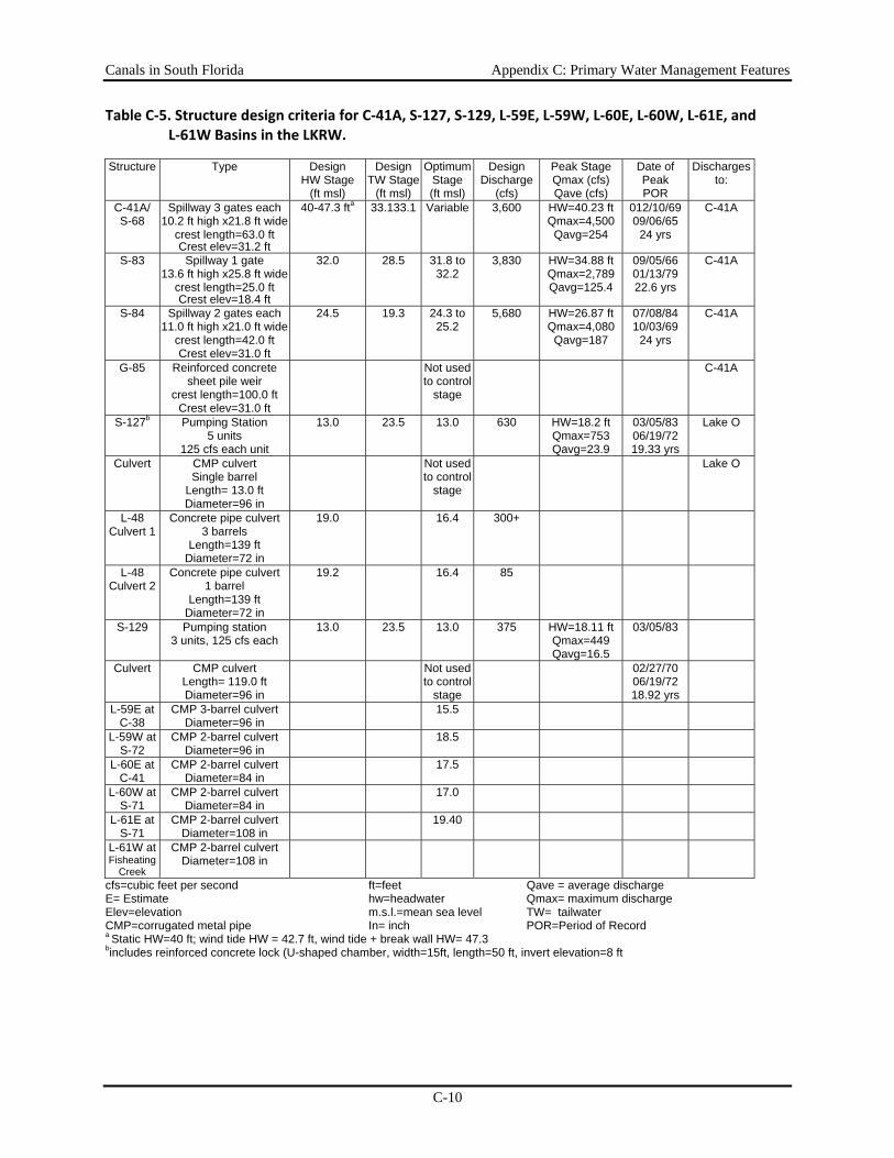
Canals in South Florida Appendix C: Primary Water Management Features
C-10
Table C‐5. Structure design criteria for C‐41A, S‐127, S‐129, L‐59E, L‐59W, L‐60E, L‐60W, L‐61E, and L‐61W Basins in the LKRW.
Structure Type Design HW Stage
(ft msl)
Design TW Stage
(ft msl)
Optimum Stage (ft msl)
Design Discharge
(cfs)
Peak StageQmax (cfs) Qave (cfs)
Date of Peak POR
Discharges to:
C-41A/ S-68
Spillway 3 gates each 10.2 ft high x21.8 ft wide
crest length=63.0 ft Crest elev=31.2 ft
40-47.3 fta 33.133.1 Variable 3,600 HW=40.23 ft Qmax=4,500 Qavg=254
012/10/69 09/06/65
24 yrs
C-41A
S-83 Spillway 1 gate 13.6 ft high x25.8 ft wide
crest length=25.0 ft Crest elev=18.4 ft
32.0 28.5 31.8 to 32.2
3,830 HW=34.88 ft Qmax=2,789 Qavg=125.4
09/05/66 01/13/79 22.6 yrs
C-41A
S-84 Spillway 2 gates each 11.0 ft high x21.0 ft wide
crest length=42.0 ft Crest elev=31.0 ft
24.5 19.3 24.3 to 25.2
5,680 HW=26.87 ft Qmax=4,080 Qavg=187
07/08/84 10/03/69
24 yrs
C-41A
G-85 Reinforced concrete sheet pile weir
crest length=100.0 ft Crest elev=31.0 ft
Not used to control
stage
C-41A
S-127b Pumping Station 5 units
125 cfs each unit
13.0 23.5 13.0 630 HW=18.2 ft Qmax=753 Qavg=23.9
03/05/83 06/19/72 19.33 yrs
Lake O
Culvert CMP culvert Single barrel
Length= 13.0 ft Diameter=96 in
Not used to control
stage
Lake O
L-48 Culvert 1
Concrete pipe culvert 3 barrels
Length=139 ft Diameter=72 in
19.0 16.4 300+
L-48 Culvert 2
Concrete pipe culvert 1 barrel
Length=139 ft Diameter=72 in
19.2 16.4 85
S-129 Pumping station 3 units, 125 cfs each
13.0 23.5 13.0 375 HW=18.11 ft Qmax=449 Qavg=16.5
03/05/83
Culvert CMP culvert Length= 119.0 ft Diameter=96 in
Not used to control
stage
02/27/70 06/19/72 18.92 yrs
L-59E at C-38
CMP 3-barrel culvert Diameter=96 in
15.5
L-59W at S-72
CMP 2-barrel culvert Diameter=96 in
18.5
L-60E at C-41
CMP 2-barrel culvert Diameter=84 in
17.5
L-60W at S-71
CMP 2-barrel culvert Diameter=84 in
17.0
L-61E at S-71
CMP 2-barrel culvert Diameter=108 in
19.40
L-61W at Fisheating
Creek
CMP 2-barrel culvert Diameter=108 in
cfs=cubic feet per second ft=feet Qave = average discharge E= Estimate hw=headwater Qmax= maximum discharge Elev=elevation m.s.l.=mean sea level TW= tailwater CMP=corrugated metal pipe In= inch POR=Period of Record a Static HW=40 ft; wind tide HW = 42.7 ft, wind tide + break wall HW= 47.3 bincludes reinforced concrete lock (U-shaped chamber, width=15ft, length=50 ft, invert elevation=8 ft
Canals in South Florida Appendix C: Primary Water Management Features
C-11
Other Basins that Discharge to C-38 Three other basins discharge water into the section of the C-38 canal downstream of S-6E, before the canal reaches Lake Okeechobee. The L-59E basin has an area of 22.5 square miles. The land use in the basin is agricultural, although most of the area is improved pasture for beef cattle production. Runoff from the L-59E basin collects in the L-59 borrow canal and flows east to C-38 through the L-59E basin culvert located through the C-38 levee. The S-154 basin has an area of 49.41 square miles and is located on the west side of the town of Okeechobee. The land use in the basin is urban and agricultural. Urban lands are within the northwest section of the town of Okeechobee. Agriculture includes citrus, beef cattle production, and dairy operations. The S-154 culvert is located on the L-D4 canal and discharges to C-38. The S-154C basin has an area of 3.4 square miles and is located along the southwest corner of the S-154 basin. The land use in the basin is agricultural including improved pasture, cattle production, citrus groves, and dairy operations. The major water control structure in this basin is the S-154C culvert, which discharges through L-D4, about 5 miles west of the town of Okeechobee.
Major Canals Downstream of Lake Istokpoga
C-41A Canal (Discharges to C-38) C-41A (Stub Canal or Brighton Canal) is the main outlet for Lake Istokpoga. The canal is about 20.1 miles long and the width varies between 30 and 130 feet. The bottom elevation ranges between -8.0 to 24.0 feet NGVD. The design water surface elevation ranges from 19.3 to 40.0 feet NGVD. There are four major water control structures in the basin: S-68, S-83, S-84, and G-85. Land use in this basin is primarily agricultural (citrus groves and vegetable production), as well as improved pastures and beef cattle production. During wet periods, drainage water is released to C-41A; during dry periods, irrigation water is drawn from the C-41A. S-68, which is located at the outlet of Lake Istokpoga, is used to maintain optimum upstream stage in Lake Istokpoga, regulate releases during floods, maintain downstream stages, and provide irrigation water during dry periods. G-85, on the Istokpoga Canal, is used as an auxiliary outlet for Lake Istokpoga whenever the lake stage is above regulation and when S-68 or the lower canals are not able to remove the high flows.
C-40 Canal (Discharges to Lake Okeechobee) The Indian Prairie Canal (C-40) is about 18.1 miles long with a bottom width of 20 to 50 feet. The bottom elevation ranges between -4.7 and 10.1 feet NGVD. The design water surface elevation is in the range of 18.6 to 25.9 feet NGVD. Land use in this basin is agricultural, including citrus groves, vegetable production, improved pasture, and cattle production. There are three major structures in the C-40 basin: S-72, S-75, and G-208. S-72 is located on the C-40 canal, about 4 miles upstream from Lake Okeechobee. S-75 is located on C-40 about 10 miles upstream from S-72. Both S-72 and S-75 maintain upstream water control stages in C-40, pass the design flood flow during high water periods, and provide flow to maintain downstream stage and meet irrigation demands during dry periods. G-208 is a pumping station thatsupplies water from Lake Okeechobee to C-40 when the stage is lower than 20.2 feet NGVD.
Canals in South Florida Appendix C: Primary Water Management Features
C-12
C-41 and C-39A Canals (Discharges to Lake Okeechobee) C-41 (Harney Pond Canal) is about 28.1 miles long and has a bottom width of 20 to 70 feet. The bottom elevation ranges from -13.0 to 16.7 feet NGVD. The design water surface elevation ranges between 18.6 to 32.5 feet NGVD. The land use in the C-41 basin is primarily agricultural, with citrus production in the higher elevations and mainly improved pasture for beef cattle production in the lower-lying lands. Truck crop and caladium production is also practiced. Four major water control structures are in the C-41 basin: S-70, S-71, S-82, and G-207. S-71 and S-70 maintain optimum upstream stages in C-41, pass flood waters during wet period, and maintain downstream stages and supply irrigation water during dry periods. S-82 is located on the C-41, 5 miles downstream from Lake Istokpoga and 500 feet downstream from the junction of C-41 and C-41A. This structure regulates discharges from C-41A into C-41. The G-207 pump station supplies water from Lake Okeechobee to the C-41 canal when Lake Istokpoga is below its regulatory schedule. The C-39A canal connects the C-40 and C-41A canals, is 3.2 miles long, and has a bottom width of 20 feet. The C-39A bottom elevation ranges from 19 to 20.2 feet NGVD and its design water surface elevation is 25.9 to 25.2 feet NGVD.
Other Basins that Discharge to C-40 and C-41 (L59W, L-60E, L-60W, L-61E) The L-59W basin has an area of 9.96 square miles. Land use in the basin is agriculture, with most of the area improved pasture for beef cattle production. Runoff from the L-59W basin collects into the L-59W borrow canal, and flows west to C-40 through the L-59W basin culvert. Interceptor levee 60 runs parallel to the northwest shore of Lake Okeechobee, immediately southwest of L-59, between the C-40 and C-41 canals. The land use in the L-60E and L-60W basins is agricultural; mostly improved pasture for beef cattle production. The L-60E basin has an area of 7.9 square miles and drains to C-40 through the L-60E basin culvert. The L-60W basin has an area of 5.1 square miles and drains to C-41 through the L-60W basin culvert. Interceptor levee 61 runs parallel to the northwest shore of Lake Okeechobee, immediately southwest of L-60, between the C-41 canal and the L-50 levee. The L-61E basin has an area of 23.4 square miles and land use in the basin is agricultural. There are some citrus groves, but most of the area is improved pasture for beef cattle production. The Seminole Tribe operates a bypass from S-71 to supply water to the L-61E basin. The tribe also operates a 90 cfs pump to supply water to this basin.
Basins that Flow Directly to Lake Okeechobee Basins associated with five District Structures S-131, S-133, S-127 and S-129 and S-193 discharge through District water control structures directly to Lake Okeechobee.
Canals in South Florida Appendix C: Primary Water Management Features
C-13
Water Conservation Areas and Everglades National Park The primary canal system associated with the Water Conservation Areas (WCAs) and and Everglades National Park (ENP) consists of the major regional canals that connect Lake Okeechobee with the lower east coast canals and the canals and the peripheral canals associated with the boundaries of the WCAs and the ENP (Figure C-3). Features of the primary canals are summarized in Table C-6, and the associated structures are described in Tables C-7 to C-12.
Major Regional Canals and Structures The primary water management system in the ENP and WCAs includes four major canals that deliver water from Lake Okeechobee south and east toward the coast – the West Palm Beach, Hillsboro, North New River, and Miami canals (Table C-6). These canals provide outlets for excess water from Lake Okeechobee when the lake is above its regulation schedule, are conduits for delivery of water from the lake during dry periods to maintain water levels in the WCAs and to meet water supply needs in the Everglades Agricultural Area (EAA) and coastal basins.
West Palm Beach Canal (L-10/L-12 Borrow Canal) (WCA-1)
The L-10/L-12 borrow canal is also called the West Palm Beach Canal west of L-8. East of L-8, the West Palm Beach Canal is known as the C-51. The L-10/L-12 borrow canal connects to Lake Okeechobee by way of S-352 at the north end of the canal at the town of Canal Point. The connection of the canal to WCA-1 is by way of S-5A at the southern end of the canal. Although releases can be made from the lake to WCA-1 via S-5A, such releases are rare events. The L-10/L-12 borrow canal also connects, at its southern end, to the L-8 borrow canal by way of S-5AW and thus connect to the WCA when S-5AW is open.
Hillsboro Canal and L-39 (WCA-1), WCA-2A The Hillsboro Canal connects to Lake Okeechobee by way of S-2 at the north end of the canal at South Bay and to WCA-1 by way of the S-6 pump station at the intersection of L-6 and L-7 on the west side of the WCA. From S-6, the Hillsboro Canal passes through WCA-1. The L-39 levee is adjacent to the canal on the north side and forms the southwestern boundary of WCA-1.
Miami Canal (WCA-3A and WCA-3B) The Miami Canal enters WCA-3A at S-8 and passes from northwest to southeast leaving WCA-3A and entering WCA-3B at S-151. The canal continues to the southeast entering tidewater at Biscayne Bay. Most of the Miami Canal within WCA-3A is known as C-123. The Miami Canal primarily affects water management in WCA-3B. C-304 is that section of the Miami Canal from S-151 to S-31. It crosses the upper quarter of WCA-3B from northwest to southeast and is used primarily to .convey water across the WCA from either Lake Okeechobee or WCA 3A to eastern Miami-Dade County and southeastern ENP. S-337 controls flow out of WCA-3B and into the Miami Canal. The reaches of the Miami Canal west of WCA-3B (i.e., C-123 and the L-23/L-24 borrow canal) convey water to WCA-3B from Lake Okeechobee and WCA-3A. Structures S-339 and S-340 control flow within WCA-3A and are operated to help prevent excess drainage of the northern and central portions of the WCA and to force water out of C-123 and into the surrounding wetlands.
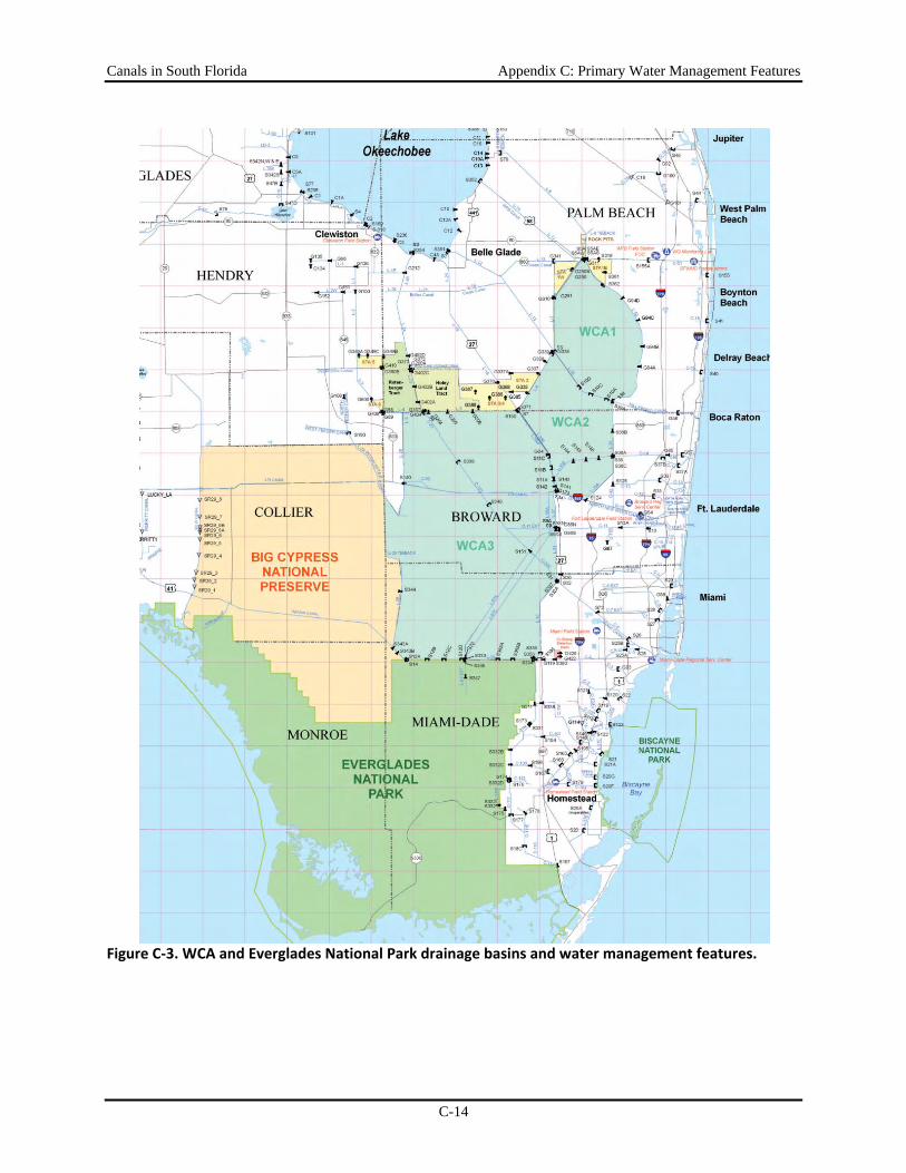
Canals in South Florida Appendix C: Primary Water Management Features
C-14
Figure C‐3. WCA and Everglades National Park drainage basins and water management features.
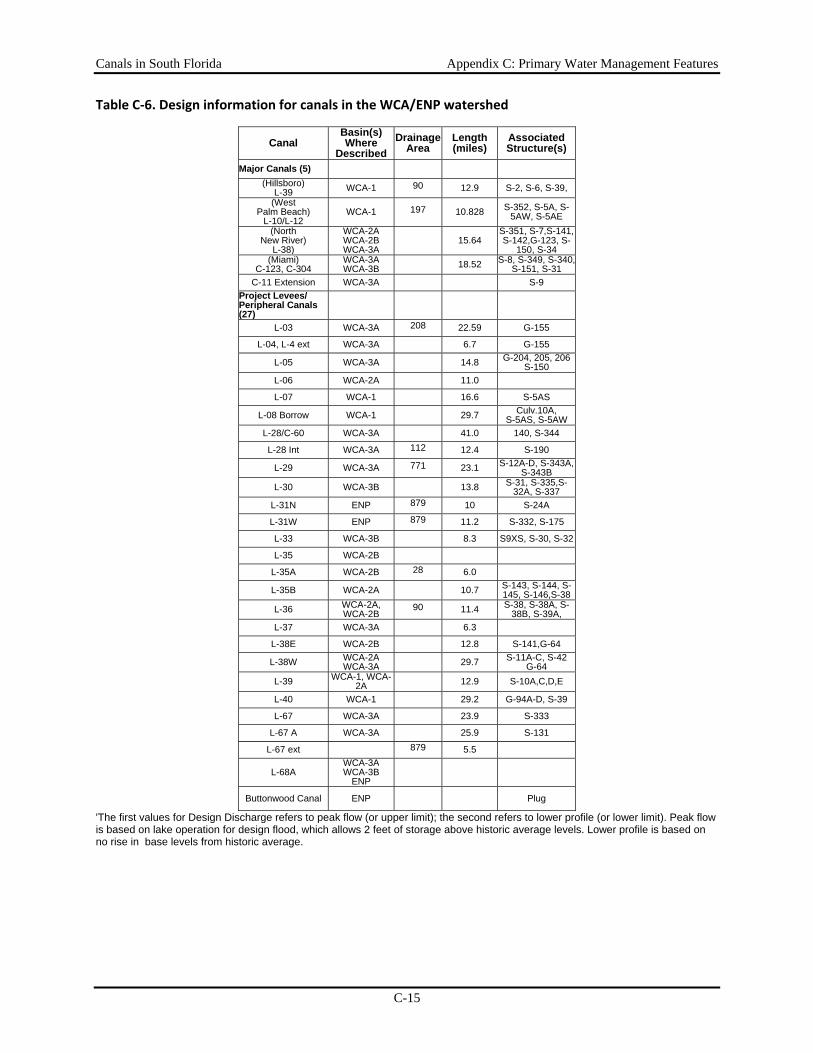
Canals in South Florida Appendix C: Primary Water Management Features
C-15
Table C‐6. Design information for canals in the WCA/ENP watershed
Canal Basin(s) Where
DescribedDrainage
Area Length (miles)
Associated Structure(s)
Major Canals (5) (Hillsboro)
L-39 WCA-1 90 12.9 S-2, S-6, S-39, (West
Palm Beach) L-10/L-12
WCA-1 197 10.828 S-352, S-5A, S-5AW, S-5AE
(North New River)
L-38)
WCA-2AWCA-2B WCA-3A
15.64 S-351, S-7,S-141, S-142,G-123, S-
150, S-34(Miami)
C-123, C-304 WCA-3AWCA-3B
18.52 S-8, S-349, S-340, S-151, S-31
C-11 Extension WCA-3A S-9 Project Levees/ Peripheral Canals (27)
L-03 WCA-3A 208 22.59 G-155
L-04, L-4 ext WCA-3A 6.7 G-155
L-05 WCA-3A 14.8 G-204, 205, 206S-150
L-06 WCA-2A 11.0
L-07 WCA-1 16.6 S-5AS
L-08 Borrow WCA-1 29.7 Culv.10A, S-5AS, S-5AW
L-28/C-60 WCA-3A 41.0 140, S-344
L-28 Int WCA-3A 112 12.4 S-190
L-29 WCA-3A 771 23.1 S-12A-D, S-343A, S-343B
L-30 WCA-3B 13.8 S-31, S-335,S-32A, S-337
L-31N ENP 879 10 S-24A
L-31W ENP 879 11.2 S-332, S-175
L-33 WCA-3B 8.3 S9XS, S-30, S-32
L-35 WCA-2B
L-35A WCA-2B 28 6.0
L-35B WCA-2A 10.7 S-143, S-144, S-145, S-146,S-38
L-36 WCA-2A, WCA-2B
90 11.4 S-38, S-38A, S-38B, S-39A,
L-37 WCA-3A 6.3
L-38E WCA-2B 12.8 S-141,G-64
L-38W WCA-2AWCA-3A
29.7 S-11A-C, S-42G-64
L-39 WCA-1, WCA-2A
12.9 S-10A,C,D,E
L-40 WCA-1 29.2 G-94A-D, S-39
L-67 WCA-3A 23.9 S-333
L-67 A WCA-3A 25.9 S-131
L-67 ext 879 5.5
L-68A WCA-3AWCA-3B
ENP
Buttonwood Canal ENP Plug
'The first values for Design Discharge refers to peak flow (or upper limit); the second refers to lower profile (or lower limit). Peak flow is based on lake operation for design flood, which allows 2 feet of storage above historic average levels. Lower profile is based on no rise in base levels from historic average.
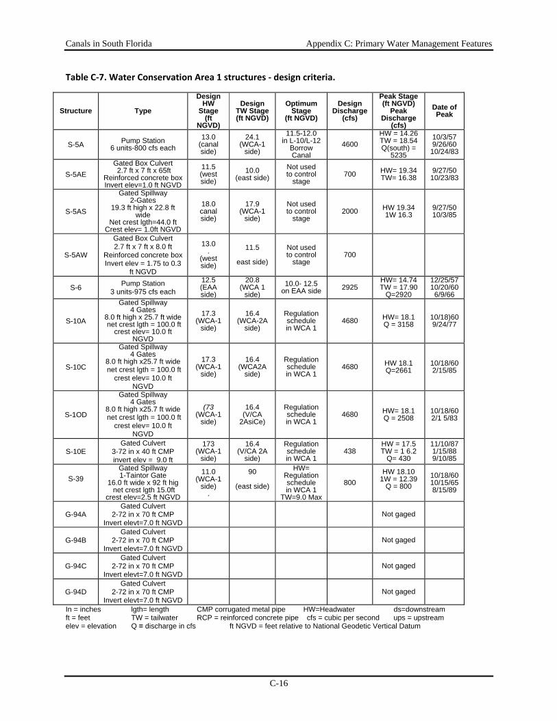
Canals in South Florida Appendix C: Primary Water Management Features
C-16
Table C‐7. Water Conservation Area 1 structures ‐ design criteria.
Structure Type
Design HW
Stage (ft
NGVD)
Design TW Stage (ft NGVD)
Optimum Stage
(ft NGVD)
Design Discharge
(cfs)
Peak Stage (ft NGVD)
Peak Discharge
(cfs)
Date of Peak
S-5A Pump Station 6 units-800 cfs each
13.0 (canal side)
24.1 (WCA-1
side)
11.5-12.0 in L-10/L-12
Borrow Canal
4600 HW = 14.26 TW = 18.54 Q(south) =
5235
10/3/57 9/26/60
10/24/83
S-5AE Gated Box Culvert 2.7 ft x 7 ft x 65ft
Reinforced concrete box Invert elev=1.0 ft NGVD
11.5 (west side)
10.0 (east side)
Not used to control
stage 700 HW= 19.34
TW= 16.38 9/27/50
10/23/83
S-5AS
Gated Spillway 2-Gates
19.3 ft high x 22.8 ft wide
Net crest lgth=44.0 ft Crest elev= 1.0ft NGVD
18.0 canal side)
17.9 (WCA-1
side)
Not used to control
stage 2000 HW 19.34
1W 16.3 9/27/50 10/3/85
S-5AW
Gated Box Culvert 2.7 ft x 7 ft x 8.0 ft
Reinforced concrete box Invert elev = 1.75 to 0.3
ft NGVD
13.0 .
(west side)
11.5
east side)
Not used to control
stage 700
S-6 Pump Station 3 units-975 cfs each
12.5 (EAA side)
20.8 (WCA 1
side) 10.0- 12.5
on EAA side 2925 HW= 14.74 TW = 17.90
Q=2920
12/25/57 10/20/60 6/9/66
S-10A
Gated Spillway 4 Gates
8.0 ft high x 25.7 ft wide net crest lgth = 100.0 ft
crest elev= 10.0 ft NGVD
17.3 (WCA-1
side)
16.4 (WCA-2A
side)
Regulation schedule in WCA 1
4680 HW= 18.1 Q = 3158
10/18)60 9/24/77
S-10C
Gated Spillway 4 Gates
8.0 ft high x25.7 ft wide net crest lgth = 100.0 ft
crest elev= 10.0 ft NGVD
17.3 (WCA-1
side)
16.4 (WCA2A
side)
Regulation schedule in WCA 1
4680 HW 18.1 Q=2661
10/18/60 2/15/85
S-1OD
Gated Spillway 4 Gates
8.0 ft high x25.7 ft wide net crest lgth = 100.0 ft
crest elev= 10.0 ft NGVD
(73 (WCA-1
side)
16.4 (V/CA
2AsiCe)
Regulation schedule in WCA 1
4680 HW= 18.1 Q = 2508
10/18/60 2/1 5/83
S-10E Gated Culvert
3-72 in x 40 ft CMP invert elev = 9.0 ft
173 (WCA-1
side)
16.4 (V/CA 2A
side)
Regulation schedule in WCA 1
438 HW = 17.5 TW = 1 6.2
Q= 430
11/10/87 1/15/88 9/10/85
S-39
Gated Spillway1-Taintor Gate
16.0 ft wide x 92 ft hig net crest lgth 15.0ft
crest elev=2.5 ft NGVD
11.0 (WCA-1
side) .
90
(east side)
HW= Regulation schedule in WCA 1
TW=9.0 Max
800 HW 18.10
1W = 12.39 Q = 800
10/18/60 10/15/65 8/15/89
G-94A Gated Culvert
2-72 in x 70 ft CMP Invert elevt=7.0 ft NGVD
Not gaged
G-94B Gated Culvert
2-72 in x 70 ft CMP Invert elevt=7.0 ft NGVD
Not gaged
G-94C Gated Culvert
2-72 in x 70 ft CMP Invert elevt=7.0 ft NGVD
Not gaged
G-94D Gated Culvert
2-72 in x 70 ft CMP Invert elevt=7.0 ft NGVD
Not gaged
In = inches lgth= length CMP corrugated metal pipe HW=Headwater ds=downstream ft = feet TW = tailwater RCP = reinforced concrete pipe cfs = cubic per second ups = upstream elev = elevation Q = discharge in cfs ft NGVD = feet relative to National Geodetic Vertical Datum
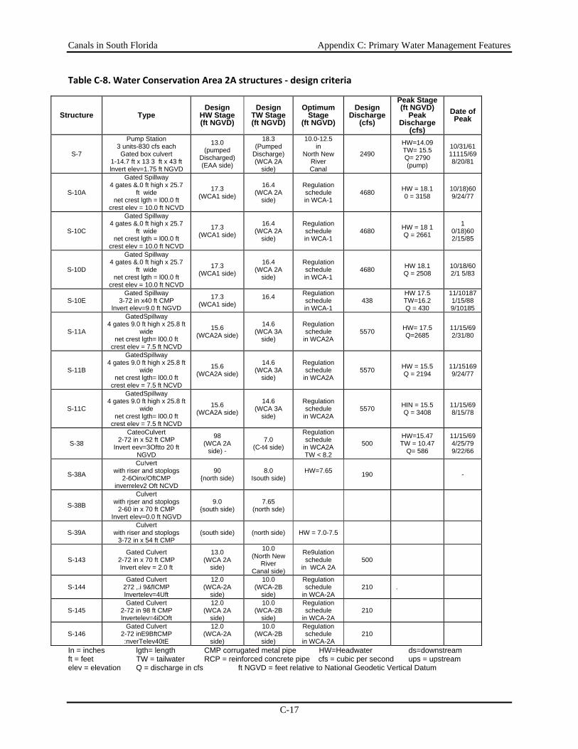
Canals in South Florida Appendix C: Primary Water Management Features
C-17
Table C‐8. Water Conservation Area 2A structures ‐ design criteria
Structure Type Design
HW Stage (ft NGVD)
Design TW Stage (ft NGVD)
Optimum Stage
(ft NGVD)
Design Discharge
(cfs)
Peak Stage (ft NGVD)
Peak Discharge
(cfs)
Date of Peak
S-7
Pump Station 3 units-830 cfs each Gated box culvert
1-14.7 ft x 13 3 ft x 43 ft lnvert elev=1.75 ft NGVD
13.0 (pumped
Discharged) (EAA side)
18.3 (Pumped
Discharge) (WCA 2A
side)
10.0-12.5 in
North New River Canal
2490
HW=14.09 TW= 15.5 Q= 2790 (pump)
10/31/61 11115/69 8/20/81
S-10A
Gated Spillway 4 gates &.0 ft high x 25.7
ft wide net crest lgth = l00.0 ft
crest elev = 10.0 ft NCVD
17.3 (WCA1 side)
16.4 (WCA 2A
side)
Regulation schedule in WCA-1
4680 HW = 18.1 0 = 3158
10/18)60 9/24/77
S-10C
Gated Spillway 4 gates &.0 ft high x 25.7
ft wide net crest lgth = l00.0 ft
crest elev = 10.0 ft NCVD
17.3 (WCA1 side)
16.4 (WCA 2A
side)
Regulation schedule in WCA-1
4680 HW = 18 1 Q = 2661
1 0/18)60 2/15/85
S-10D
Gated Spillway 4 gates &.0 ft high x 25.7
ft wide net crest lgth = l00.0 ft
crest elev = 10.0 ft NCVD
17.3 (WCA1 side)
16.4 (WCA 2A
side)
Regulation schedule in WCA-1
4680 HW 18.1 Q = 2508
10/18/60 2/1 5/83
S-10E Gated Spillway
3-72 in x40 ft CMP lnvert elev=9.0 ft NGVD
17.3 (WCA1 side)
16.4
Regulation schedule in WCA-1
438 HW 17.5 TW=16.2 Q = 430
11/101871/15/88 9/10185
S-11A
GatedSpillway 4 gates 9.0 ft high x 25.8 ft
wide net crest lgth= l00.0 ft
crest elev = 7.5 ft NCVD
15.6 (WCA2A side)
14.6 (WCA 3A
side)
Regulation schedule
in WCA2A 5570 HW= 17.5
Q=2685 11/15/69 2/31/80
S-11B
GatedSpillway 4 gates 9.0 ft high x 25.8 ft
wide net crest lgth= l00.0 ft
crest elev = 7.5 ft NCVD
15.6 (WCA2A side)
14.6 (WCA 3A
side)
Regulation schedule
in WCA2A 5570 HW = 15.5
Q = 2194 11/15169 9/24/77
S-11C
GatedSpillway 4 gates 9.0 ft high x 25.8 ft
wide net crest lgth= l00.0 ft
crest elev = 7.5 ft NCVD
15.6 (WCA2A side)
14.6 (WCA 3A
side)
Regulation schedule
in WCA2A 5570 HIN = 15.5
Q = 3408 11/15/69 8/15/78
S-38
CateoCulvert 2-72 in x 52 ft CMP
Invert eev=3Oftto 20 ft NGVD
98 (WCA 2A
side) -
7.0 (C-t4 side)
Regulation schedule
in WCA2A TW < 8.2
500 HW=15.47 TW = 10.47
Q= 586
11/15/69 4/25/79 9/22/66
S-38A
Cu!vert with riser and stoplogs
2-6Oinx/OftCMP inverrelev2 Oft NCVD
90 {north side)
8.0 Isouth side)
HW=7.65 190 -
S-38B
Culvert with rjser and stoplogs
2-60 in x 70 ft CMP Invert elev=0.0 ft NGVD
9.0 {south side)
7.65 (north sde)
S-39A Culvert
with riser and stoplogs 3-72 in x 54 ft CMP
(south side) (north side) HW = 7.0-7.5
S-143 Gated Culvert
2-72 in x 70 ft CMP Invert elev = 2.0 ft
13.0 (WCA 2A
side)
10.0 (North New
River Canal side)
Re9ulation schedule
in WCA 2A 500
S-144 Gated Culvert
272 ,.i 9&fICMP lnvertelev=4Uft
12.0 (WCA-2A
side)
10.0 (WCA-2B
side)
Regulation schedule
in WCA-2A 210 .
S-145 Gated Culvert
2-72 in 98 ft CMP lnvertelev=4iDOft
12.0 (WCA 2A
side)
10.0 (WCA-2B
side)
Regulation schedule
in WCA-2A 210
S-146 Gated Culvert
2-72 inE9BftCMP :nverTelev40tE
12.0 (WCA-2A
side)
10.0 (WCA-2B
side)
Regulation schedule
in WCA-2A 210
In = inches lgth= length CMP corrugated metal pipe HW=Headwater ds=downstream ft = feet TW = tailwater RCP = reinforced concrete pipe cfs = cubic per second ups = upstream elev = elevation Q = discharge in cfs ft NGVD = feet relative to National Geodetic Vertical Datum
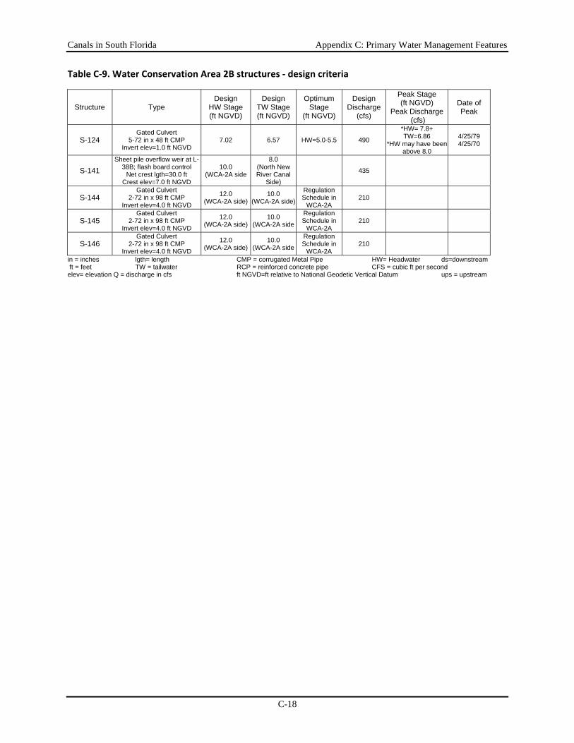
Canals in South Florida Appendix C: Primary Water Management Features
C-18
Table C‐9. Water Conservation Area 2B structures ‐ design criteria
Structure Type Design
HW Stage (ft NGVD)
Design TW Stage (ft NGVD)
Optimum Stage
(ft NGVD)
Design Discharge
(cfs)
Peak Stage (ft NGVD)
Peak Discharge (cfs)
Date of Peak
S-124 Gated Culvert
5-72 in x 48 ft CMP Invert elev=1.0 ft NGVD
7.02 6.57 HW=5.0-5.5 490
*HW= 7.8+ TW=6.86
*HW may have been above 8.0
4/25/79 4/25/70
S-141 Sheet pile overflow weir at L-
38B; flash board control Net crest lgth=30.0 ft
Crest elev=7.0 ft NGVD
10.0 (WCA-2A side
8.0 (North New River Canal
Side)
435
S-144 Gated Culvert
2-72 in x 98 ft CMP Invert elev=4.0 ft NGVD
12.0 (WCA-2A side)
10.0 (WCA-2A side)
Regulation Schedule in
WCA-2A 210
S-145 Gated Culvert
2-72 in x 98 ft CMP Invert elev=4.0 ft NGVD
12.0 (WCA-2A side)
10.0 (WCA-2A side
Regulation Schedule in
WCA-2A 210
S-146 Gated Culvert
2-72 in x 98 ft CMP Invert elev=4.0 ft NGVD
12.0 (WCA-2A side)
10.0 (WCA-2A side
Regulation Schedule in
WCA-2A 210
in = inches lgth= length CMP = corrugated Metal Pipe HW= Headwater ds=downstream ft = feet TW = tailwater RCP = reinforced concrete pipe CFS = cubic ft per second elev= elevation Q = discharge in cfs ft NGVD=ft relative to National Geodetic Vertical Datum ups = upstream
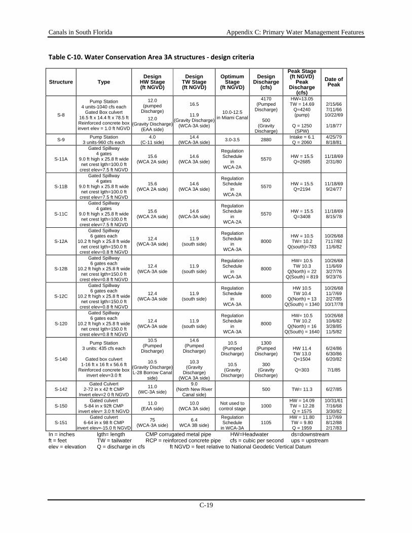
Canals in South Florida Appendix C: Primary Water Management Features
C-19
Table C‐10. Water Conservation Area 3A structures ‐ design criteria
Structure Type Design
HW Stage (ft NGVD)
Design TW Stage (ft NGVD)
Optimum Stage
(ft NGVD)
Design Discharge
(cfs)
Peak Stage (ft NGVD)
Peak Discharge
(cfs)
Date of Peak
S-8
Pump Station 4 units-1040 cfs each
Gated Box culvert 16.5 ft x 14.4 ft x 78.5 ft Reinforced concrete box invert elev = 1.0 ft NGVD
12.0 (pumped
Discharge) 12.0
(Gravity Discharge) (EAA side)
16.5
11.9 (Gravity Discharge)
(WCA-3A side)
10.0-12.5 in Miami Canal
4170 (Pumped
Discharge}
500 (Gravity
Discharge)
HW=13.05 TW = 14.69
Q=4240 (pump)
Q = 1250
(SPW)
2/15/66 7/11/66
10/22/69
1/18/77
S-9 Pump Station 3 units-960 cfs each
4.0 (C-11 side)
14.4 (WCA-3A side) 3.0-3.5 2880 Intake = 6.1
Q = 2060 4/25/79 8/18/81
S-11A
Gated Spillway 4 gates
9.0 ft high x 25.8 ft wide net crest lgth=100.0 ft
crest elev=7.5 ft NGVD
15.6 (WCA 2A side)
14.6 (WCA 3A side)
Regulation Schedule
in WCA-2A
5570 HW = 15.5 Q=2685
11/18/69 2/31/80
S-11B
Gated Spillway 4 gates
9.0 ft high x 25.8 ft wide net crest lgth=100.0 ft
crest elev=7.5 ft NGVD
15.6 (WCA 2A side)
14.6 (WCA 3A side)
Regulation Schedule
in WCA-2A
5570 HW = 15.5 Q=2194
11/18/69 9/24/77
S-11C
Gated Spillway 4 gates
9.0 ft high x 25.8 ft wide net crest lgth=100.0 ft
crest elev=7.5 ft NGVD
15.6 (WCA 2A side)
14.6 (WCA-3A side)
Regulation Schedule
in WCA-2A
5570 HW = 15.5 Q=3408
11/18/69 8/15/78
S-12A
Gated Spillway 6 gates each
10.2 ft high x 25.8 ft wide net crest lgth=150.0 ft
crest elev=0.8 ft NGVD
12.4 (WCA-3A side)
11.9 (south side)
Regulation Schedule
in WCA-3A
8000 HW = 10.5 TW= 10.2
Q(south)=783
10/26/68 7117/82 11/6/82
S-12B
Gated Spillway 6 gates each
10.2 ft high x 25.8 ft wide net crest lgth=150.0 ft
crest elev=0.8 ft NGVD
12.4 (WCA-3A side
11.9 (south side)
Regulation Schedule
in WCA-3A
8000
HW= 10.5 TW 10.3
Q(North) = 22 Q(South) = 819
10/26/68 11/6/69 3/27/76 9/23/76
S-12C
Gated Spillway 6 gates each
10.2 ft high x 25.8 ft wide net crest lgth=150.0 ft
crest elev=0.8 ft NGVD
12.4 (WCA-3A side
11.9 (south side)
Regulation Schedule
in WCA-3A
8000
HW 10.5 TW 10.4
Q(North) = 13 Q(South) = 1340
10/26/68 11/7/69 2/27/85
10/17/78
S-120
Gated Spillway 6 gates each
10.2 ft high x 25.8 ft wide net crest lgth=150.0 ft
crest elev=0.8 ft NGVD
12.4 (WCA-3A side
11.9 (south side)
Regulation Schedule
in WCA-3A
8000
HW= 10.5 TW 10.2
Q(North) = 16 Q(South) = 1640
10/26/68 10/6/82 3/28/85 11/5/82
S-140
Pump Station 3 units: 435 cfs each
Gated box culvert
1-16 ft x 16 ft x 56.6 ft Reinforced concrete box
invert elev=3.0 ft
10.5 (Pumped
Discharge)
10.5 (Gravity Discharge) L-28 Borrow Canal
side)
14.6 (Pumped
Discharge)
10.3 (Gravity
Discharge) (WCA 3A side)
10.5 (Pumped
Discharge)
10.5 (Gravity
Discharge)
1300 (Pumped
Discharge)
300 (Gravity
Discharge)
HW 11.4 TW 13.0 Q=1504
Q=303
6/24/86 6/30/86 6/20/82
7/1/85
S-142 Gated Culvert
2-72 in x 42 ft CMP Invert elev=2 0 ft NGVD
11.0 (WC-3A side)
9.0 (North New River
Canal side) 500 TW= 11.3 6/27/85
S-150 Gated culvert
5-84 in x 92ft CMP invert elev= 3.0 ft NGVD
11.0 (EAA side)
10.0 (WCA 3A side)
Not used to control stage 1000
HW = 14.09 TW = 12.28 Q = 1575
10/31/61 7/16/68 3/30/82
S-151 Gated culvert
6-64 in x 98 ft CMP invert elev=-15.0 ft NGVD
75 (WCA-3A side)
6.4 WCA 3B side)
Regulation Schedule
in WCA-3A 1105
HW = 11.80 TW = 9.80 Q = 1959
11/7/69 8/12/88 2/17/83
In = inches lgth= length CMP corrugated metal pipe HW=Headwater ds=downstream ft = feet TW = tailwater RCP = reinforced concrete pipe cfs = cubic per second ups = upstream elev = elevation Q = discharge in cfs ft NGVD = feet relative to National Geodetic Vertical Datum
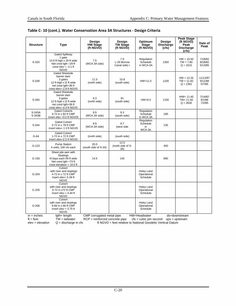
Canals in South Florida Appendix C: Primary Water Management Features
C-20
Table C‐ 10 (cont.). Water Conservation Area 3A Structures ‐ Design Criteria
Structure Type Design
HW Stage (ft NGVD)
Design TW Stage (ft NGVD)
Optimum Stage
(ft NGVD)
Design Discharge
(cfs)
Peak Stage (ft NGVD)
Peak Discharge
(cfs)
Date of Peak
S-333
Gated Spillway 1-gate
14.6 ft high x 29 ft wide Net crest lgth =29 ft crest elev = -3.1 ft
NGVD
7.5 (WCA 3A side)
7.0 L-29 Borrow Canal side) •
Regulation Schedule
in WCA-3A 1350
HW = 10.50 TW = 7.80 Q = 1610
7/18/82 8/18/82 5/14/85
S-339
Gated Sheetoile barrier dam
3 gates 12 ft high x l2 ft wide net crest lgth=36 ft
crest elev=-2.8 ft NGVD
11.0 (north side)
10.8 (south side) HW=11.0 1100
HW = 12.25 TW = 11.82 Q = 1362
11/12/87 9/11/88 5/7/85
S-340
Gated Sheetoile barrier dam
3-gates 12 ft high x l2 ft wide net crest lgth=36 ft
crest elev=-4.3 ft NGVD
9.3 (north side)
91 (south side) HW=9.3 1100
HIW= 11.45 TW= 11.50 Q = 2630
7/14/82 9/1/88 7/2/85
S-343A S-343B
Gated Culverts 3-72 in x 82 ft CMP
invert elev =0.0 ft NGVDI
9.5 (WCA 3A side)
9.3 (south side)
Regulation Schedule
in WCA 3A 195
S-344 Gated Culvert
3-72 in x 78 ft CMP invert elev= 1 0 ft NGVD
9.9 (WCA-3A side)
9.7 (west side
Regulation Schedule
in WCA-3A
135
G-64 Gated Culvert
1-72 in x 72 ft CMP invert elev=2.5 ft NGVD
(north side) (south side)
G-123 Pump Station 4 units; 100 cfs each
20.0 (south side of S-34)
12.0 (north side of S-
34) 400
G-155
Sheet pile weir with Stoplogs
l4 bays each 59 ft wide Net crest lgth =73 ft
crest elevation = 10.0 ft
14.5 140 890
G-204
Culvert with riser and stoplogs
4-72 in x 72 ft CMP inyert elev= 5.39 ft
NGVD
Holey Land Operational Schedule
G-205
Culvert with riser and stoplogs
5-72 in x72 ft CMP invert elev = 4.44 ft
NGVD
Holey Land Operational Schedule
G-206
Culvert with riser and stoplogs
5-66 in x 66 ft CMP invert elev = 3.75 ft
NGVD
Holey Land Operational Schedule
in = inches lgth= length CMP corrugated metal pipe HW=Headwater ds=downstream ft = feet TW = tailwater RCP = reinforced concrete pipe cfs = cubic per second ups = upstream elev = elevation Q = discharge in cfs ft NGVD = feet relative to National Geodetic Vertical Datum
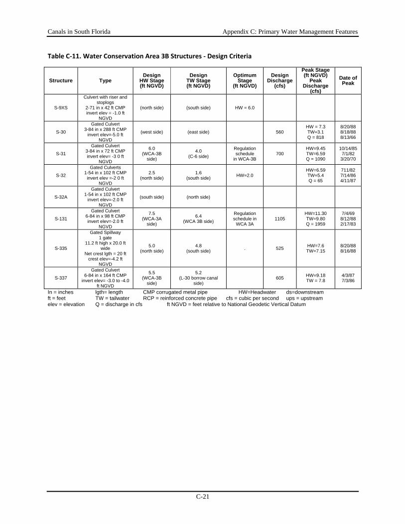
Canals in South Florida Appendix C: Primary Water Management Features
C-21
Table C‐11. Water Conservation Area 3B Structures ‐ Design Criteria
Structure Type Design
HW Stage (ft NGVD)
Design TW Stage (ft NGVD)
Optimum Stage
(ft NGVD)
Design Discharge
(cfs)
Peak Stage (ft NGVD)
Peak Discharge
(cfs)
Date of Peak
S-9XS
Culvert with riser and stoplogs
2-71 in x 42 ft CMP invert elev = -1.0 ft
NGVD
(north side) (south side) HW = 6.0
S-30
Gated Culvert 3-84 in x 288 ft CMP
invert elev=-5.0 ft NGVD
(west side) (east side) 560 HW = 7.3 TW=3.1 Q = 818
8/20/88 8/18/88 8/13/66
S-31
Gated Culvert 3-84 in x 72 ft CMP invert elev= -3 0 ft
NGVD
6.0 (WCA-3B
side)
4.0 (C-6 side)
Regulation schedule
in WCA-3B 700
HW=9.45 TW=6.59 Q = 1090
10/14/85 7/1/82
3/20/70
S-32
Gated Culverts 1-54 in x 102 ft CMP
invert elev =-2 0 ft NGVD
2.5 (north side)
1.6 (south side) HW=2.0
HW=6.59 TW=5.4 Q = 65
711/82 7/14/86 4/11/87
S-32A
Gated Culvert 1-54 in x 102 ft CMP
invert elev=-2.0 ft NGVD
(south side) (north side)
S-131
Gated Culvert 6-84 in x 98 ft CMP invert elev=-2.0 ft
NGVD
7.5 (WCA-3A
side)
6.4 (WCA 3B side)
Regulation schedule in
WCA 3A 1105
HW=11.30 TW=9.80 Q = 1959
7/4/69 8/12/88 2/17/83
S-335
Gated Spillway 1 gate
11.2 ft high x 20.0 ft wide
Net crest lgth = 20 ft crest elev=-4.2 ft
NGVD
5.0 (north side)
4.8 (south side) . 525 HW=7.6
TW=7.15 8/20/88 8/16/88
S-337
Gated Culvert 6-84 in x 164 ft CMP
invert elev= -3.0 to -4.0 ft NGVD
5.5 (WCA-3B
side)
5.2 (L-30 borrow canal
side) 605 HW=9.18
TW = 7.8 4/3/87 7/3/86
In = inches lgth= length CMP corrugated metal pipe HW=Headwater ds=downstream ft = feet TW = tailwater RCP = reinforced concrete pipe cfs = cubic per second ups = upstream elev = elevation Q = discharge in cfs ft NGVD = feet relative to National Geodetic Vertical Datum
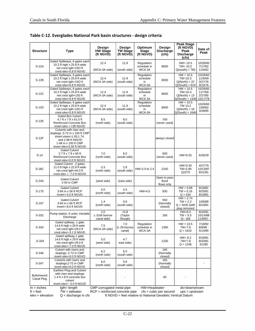
Canals in South Florida Appendix C: Primary Water Management Features
C-22
Table C‐12. Everglades National Park basin structures ‐ design criteria
Structure Type Design
HW Stage (ft NGVD)
Design TW Stage (ft NGVD)
Optimum Stage
(ft NGVD)
Design Discharge
(cfs)
Peak Stage (ft NGVD)
Peak Discharge
(cfs)
Date of Peak
S-12A
Gated Spillways, 6 gates each 10.2 ft high x 25.8 ft wide
net crest Igth=15O ft crest elev=0.8 ft NGVD
12.4
(WCA-3A side)
11.9
(south side)
Regulation schedule in
WCA 3A 8000
HW= 10.5 TW= 10.2
Q(south) = 783
10/26/60 7/17/82 11/6/82
S-12B
Gated Spillways, 6 gates each 10.2 ft high x 25.8 ft wide
net crest Igth=15O ft crest elev=0.8 ft NGVD
12.4 (WCA 3A side)
11-9 (south side)
Regulation schedule
in WCA-3A
8000
HW = 10.5 TW=10.3
Q(North) = 22 Q(South) = 819
10/26/60 11/6/69 3/27/76 9/23/76
S-12C
Gated Spillways, 6 gates each 10.2 ft high x 25.8 ft wide
net crest Igth=150 ft crest elev=0.8 ft NGVD
12.4 (WCA-3A side)
11.9 (south side)
Regulation schedule
in WCA 3A
8000
HW = 10.5 TW=10.4
Q(North) = 13 Q{South) = 1340
10/26/60 11/7/69 2/27/85
10/17/78
S-12D
Gated Spillways, 6 gates each 10.2 ft high x 25.8 ft wide
net crest Igth=15O ft crest elev=0.8 ft NGVD
12.4 (WCA-3A side)
11.9 (south side)
Regulation schedule
in WCA-3A
8000
HW = 10.5 TW 10.2
Q(North) = 16 Q(South) = 1640
10/26/60 10/6/82 3/28/85
S-12E
Gated Box Culvert 4.7 ft x 7 ft x 61.5 ft
Reinforced Concrete Box invert elev = l.0ft NGVD
8.5 (north side)
8.0 (south side) 700
(never used)
S-12F
Culverts with riser and stoplogs ;3-72 in x 100 ft CMP
irtvert elves=1.93,1 74. and 2.98 ft INGVD
1-48 in x 100 ft CMP invert elev=2.50 ft NGVD
always closed
S-14
Gated Culvert 2.7 ft x 7 ft x 65 ft
Reinforced Concrete Box invert elev=0.0 ft NGVO
7.0 (north side)
6.0 (south side) 500
(never used) HW=9.25 6/26/29
S-18C
Gated Culvert , 2 gates 11.0 ft high x 22.8 ft wide
net crest lgth=44.0 ft crest elev = -7.0 ft NGVD
3.3 (north side)
2.8 (south side) HW=2.0 to 2.4 2100
HW=3.30 TW=2.90 Q2270
4/27/79 10/13/87 8/21/81
S-24A Gated Culvert 2-54 in CMP (west side) (east side)
Open to pass flood
flows only
S-175 Gated Culvert
3-84 in x 56 ft RCP invert=-5.0 ft NGVD
5.0 {north side)
4.5 (south side) HW=4.5 500
HW = 5.85 TW = 5.16 Q = 534
8/18/81 8/20/81 8/19/81
S-197 Gated Culvert
3-84 in x 66 ft RCP invert=-8.0 ft NGVD
1.4 {north side)
0.6 (south side)
550 (Normally closed)
HW = 2.74 TW = 2.2
Q = 3430 {with plug removed
10/6/88 8/19/81
S-332 Pump station, 5 units; Variable Discharge
2.0 L-31W borrow
canal side)
<5.8 (Taylor Slough)
165 HW=6.0 TW = 5.5 Q= 166
8/20/81 10/14/88 11/9/83 -
S-333
Gated spillway, 1 gate 14.6 ft high x 29 ft wide
net crest lgth=29.0 ft crest elev=-3.1 ft NGVD
7.5 (WCA-3A side)
7.0 (L-29 borrow
canal)
Regulation schedule in
WCA-3A 1350
HW = 10.5 TW=7.8
Q = 1610
7/18/82 8/8/88 - 5/14/85
.S-334
Gated spillway,1 gate 14.6 ft high x 29 ft wide
net crest lgth=29.0 ft crest elev=-7.0 ft NGVD
5.0 (west side)
4.7 east side) 1230
HW= 8.2 TW=7.8
Q = 1246
8/18/81 8/20/81 5/1/85
S-346 Culvert with risers and stoplogs; 2-72 in CMP
invert elev=0.0 ft NGVD
6.2 (north side)
6.0 (south side)
165 (Normally closed)
S-347 Culverts with risers and stoplogs;2-72 in CMP
invert elev=0.0 ft NGVD
6.0 (north side)
5.8 (south side)
165 (Normally closed)
-
Buttonwood Canal Plug
Earthen Plug and Culvert with riser and stoplogs
1-4 ft x 8 ft concrete box culvert
invert elev= -5.0 ft NGVD
- 60 -
In = inches lgth= length CMP corrugated metal pipe HW=Headwater ds=downstream ft = feet TW = tailwater RCP = reinforced concrete pipe cfs = cubic per second ups = upstream elev = elevation Q = discharge in cfs ft NGVD = feet relative to National Geodetic Vertical Datum
Canals in South Florida Appendix C: Primary Water Management Features
C-23
Peripheral Canals The remaining canals of the primary water management system are peripheral to the WCAs and ENP. These canals provide means to manage and improve the distribution of flows into the ENP and WCAs of water from the major canals and excess water from adjacent basins.
WCA-1 The L-40 levee and borrow canals form the eastern boundary of WCA-1. The L-40 borrow canals connect from the S-5AS structure on the north end, to the junction of L-39 and the Hillsboro Canal at the south end of WCA-1. This canal provides a route to convey water from the S-5A and L-8 basins southward, where it can be discharged to the east through the Hillsboro Canal.
WCA-2 The L-35B canal connects the North New River Canal to C-13 and C-14. The canal runs west to east just north of L-35B making an open channel connection to the North New River Canal at its west end and connecting to C-14 at its east end by way of S-38. The borrow canals of the levees impounding WCA-2B on the east cut into the Biscayne Aquifer and intercept some of the groundwater flow to the east. The intercepted groundwater and seepage through the levees are an important source of water to adjacent basins in Broward County, to the C-13 and C-14 basins by seepage to the L-35A and L-36 borrow canals, and to the North New River Canal basin by seepage through L-35.
WCA-3 and ENP Water enters the north end of WCA-3A through structures along the L-5 levee. On the west side of WCA-3A, water enters from the L-28 borrow canal by way of S-140, from the L-4 cut via the L-3 extension, and from the feeder canal basin by way of the S-190 in the L-28 interceptor borrow canal. Water also enters WCA-3A as sheet flow through the L-28 gap and by way of the L-28 tieback levee borrow canal. Water from the southwest corner of WCA-3A can be discharged through L-28 to the Big Cypress Swamp. The C-60 canal conveys discharge away from S-140 so that the tailwater level at the pump remains within design conditions. L-37 and L-67A border the eastern side of WCA-3A. The C-11 Extension is located west of the L-33/L-37 levee and connects the C-11 canal to the C-123 section of the Miami Canal, to facilitate water deliveries to eastern Broward County during dry periods. The L-67A borrow canal is on the WCA-3A side of L-67A and connects the Miami Canal to S-333 and the S-12 structures. L-67C forms the western edge of WCA-3B. The various borrow canals of the levees impounding WCA-3B on the east and south (i.e., L-29, L-30, and L-33) intercept seepage from the WCA and convey this water to adjacent basins for maintenance of groundwater levels and municipal water supply. Excess water in the L-30 borrow canal is discharged south to the L-31N borrow canal by way of S-335. The rate of seepage to the L-29 borrow canal is not specifically regulated by structure operations. When required by the WCA-3A regulation schedule, excess water in the L-29 borrow canal can be discharged south to Everglades National Park by way of the S-12 structures to Northeast Shark River Slough and through S-333. The L-67 extension borrow canal serves as a "get away channel" for discharges from the S-12 structures.
Canals in South Florida Appendix C: Primary Water Management Features
C-24
Everglades Agricultural Area
Major Project Canals Features within the EAA are shown in Figure C-4, canals are characterized in Table C-13, and structures are described in Table C-14. The major canals that convey water from Lake Okeechobee south and east to coastal basins are the L-8, West Palm Beach, Hillsboro, North New River, and Miami canals. Water enters these canals from Lake Okeechobee at the north end. In the EAA basin these canals are primarily bordered by agricultural lands. When the water leaves the EAA, it is passed into and through the Stormwater Treatment Areas (STAs), when sufficient holding capacity is available, to allow for removal of nutrients, pollutants and contaminants. Water from the S-5A and L-8 basins is treated in STA-1W and STA-1E. Runoff from the S-6 Basin is treated in STA-2. Runoff from the S-7 Basin is treated in STA-3 and STA-4, and water from the S-8 Basin is treated in STA-5 and STA-6 (see Figure 11).
Releases from the lake to WCA-1 are possible by way of the Hillsboro Canal, but are rare events. The Hillsboro Canal may also be used to supply water from Lake Okeechobee to the Hillsboro Canal basin for irrigation and municipal water supply. S-10A, S-10C, and S-10D are gated spillways located in L-39 on the southwest boundary of WCA-1 that are primarily used to maintain the stage in WCA-1 at its regulation schedule. S-10E is a gated culvert located through L-39 that permits discharge of water from WCA-1 into the northern portion of WCA-2A.
North New River Canal and L-38 (WCA-2A and WCA-3A) The North New River Canal connects Lake Okeechobee to WCA-2A and WCA-3A. The connection to Lake Okeechobee is by way of S-2 and S-351. The connection with WCA-2A is by way of S-7. The North New River Canal also connects to WCA-3A by way of S-150, G-123, and S-142. From S-7, the North New River Canal passes on through WCA-2A. It is bordered by the L-38E and L-38W levees, which form boundaries of WCA-2A and WCA-3A respectively. The North New River Canal provides a means of conveying water from Lake Okeechobee to eastern Broward County. Regulatory releases from the lake can be made to WCA-2A, but are rare. The North New River Canal may be used to supply water from Lake Okeechobee to coastal Broward County basins for irrigation and municipal water supply. S-11A, S-11 C, and S-11C are gated spillways located in L-38W on the southwest boundary of WCA-2A, which are used to maintain the stage in WCA-2A at its regulation schedule. S-141 is used to make releases of water from WCA-2B to the North New River Canal to regulate the stage in the WCA and for water supply to the North New River Canal basin.
L-8 Canal The L-8 canal drains an area of 171 square miles in Palm Beach and Martin counties (Figure C-4). The canal connects Lake Okeechobee to WCA-1. The connection to Lake Okeechobee is by way of Culvert #10A and S-76 to regulate flow into or out of the lake.
The connection to WCA-1 is by way of S-5A and S-5AS. Near its southern end, L-8 intersects the L-10/L-12 borrow canal (West Palm Beach Canal). Excess water can be discharged from the L-8 basin in one of three ways: (1) to Lake Okeechobee by way of Culvert #10A; (2) to tidewater by way of S-5AE; and (3) to WCA-1 by way of either S-5AS, or S-5AW and S-365A.
Canals in South Florida Appendix C: Primary Water Management Features
C-25
Occasionally the L-8 borrow canal is used to provide conveyance of regulatory releases from Lake Okeechobee to WCA-1 or tidewater, but these are rare occurrences.
Water is supplied to the L-8 basin from Lake Okeechobee by way of Culvert #10A, from WCA-1 by way of S-5AS, and from the S-5A basin by way of S-5AW. The L-8 borrow canal can also be used to transfer water from storage in WCA-1 to storage in Lake Okeechobee. Water is supplied to the city of West Palm Beach municipal water supply system from the L-8 basin by way of a city owned and operated pump station located at the junction of the L-8 Tieback Levee borrow canal and the city of West Palm Beach's M canal. A spillway adjacent to this pump station discharges excess water from the M canal to the L-8 basin.
West Palm Beach Canal (L-10/L-12 borrow canal) The L-10/L-12 borrow canal connects Lake Okeechobee to WCA-1 and is the principal canal in the S-5A basin. The S-5A drainage basin (Figure C-4) is 194.3 square miles. The connection of the borrow canal to Lake Okeechobee is by way of S-352. The connection of the canal to WCA-1 is by way of S-5A and S-5AS. The borrow canal is also connected to C-51 and the L-8 borrow canal at its southern end. The various structures at the S-5A complex (S-5A, S-5AE, S-5AS, and S-5AW) are operated in conjunction with one another to control flood runoff from the S-5A, L-8, and western C-51 basins, to implement numerous water supply operations, and to route regulatory releases from Lake Okeechobee to WCA-1 or to tide.
Hillsboro Canal The part of the Hillsboro Canal within the EAA is also called the L-14/L-15 borrow canal. The Hillsboro Canal is located in the S-2 and S-6 drainage basins and connects Lake Okeechobee to WCA-1 (Figure C-4). The S-2 basin is 165.7 square miles in area and the S-6 basin is 132.8 square miles. The Hillsboro Canal connects to Lake Okeechobee by way of S-2 and is used to supply water from Lake Okeechobee to the S-2, S-6, and S-7 basins as needed for irrigation. Regulatory releases from Lake Okeechobee are made to the Hillsboro and North New River canals by way of S-351. Under some rare flood conditions, S-351 may discharge excess water from the basin to Lake Okeechobee. Water from the Hillsboro Canal may be discharged to WCA-1 by way of S-6 or may pass through the WCAs to eastern Palm Beach and Broward counties.
North New River Canal The North New River Canal connects Lake Okeechobee to WCA-2A and WCA-3A. The North New River Canal within the EAA is also known as the L-18/L-19 borrow canal. The connection to Lake Okeechobee is by way of S-2. Water supply releases from Lake Okeechobee are made to the North New River Canal by way of S-351 and S-2. These releases are passed to WCA-2A, and subsequently to eastern Broward County, by way of S-7. The S-7 basin is 131.3 square miles. Regulatory releases from Lake Okeechobee are made to the Hillsboro and North New River canals by way of S-351 and, under some rare flood conditions, S-351 may discharge to Lake Okeechobee. The connection with WCA-2A is by way of S-7 at the intersection of L-5 and L-6 (Figure C-4). The connection with WCA-3A is by way of S-150. Regulatory releases from Lake Okeechobee are made to the North New River Canal by way of S-351.
Canals in South Florida Appendix C: Primary Water Management Features
C-26
Miami Canal The Miami Canal is located within the S-3 and S-8 basins. The S-3 drainage basin is 101.0 square miles and the S-8 drainage basin is 201.4 square miles in area. The Miami Canal connects Lake Okeechobee to WCA-3A. The connection to Lake Okeechobee is by way of S-3 and the connection to WCA-3A is by way of S-8. Regulatory releases from Lake Okeechobee can be made to the Miami Canal by way of S-354. On the rare occasions that such releases are made, they are passed to WCA-3A by way of S-8. Water supply releases from Lake Okeechobee are made to the Miami Canal by way of S-354 and S-3. These releases are passed to WCA-3A, and subsequently to eastern Miami-Dade County and Everglades National Park by way of S-8.
Other Project Canals The Cross Canal (L-21) and Bolles Canal (L-16) extend east to west providing connections between the Miami, North New River, and Hillsboro canals. Ocean canal (L-13) provides a connection between the Hillsboro Canal and the West Palm Beach Canal. The L-6 borrow canal is located along the southeastern boundary of the S-6 basin. It connects the Hillsboro Canal to the North New River Canal. The L-5 Borrow Canal makes an open channel connection with the North New River Canal at the intersection with L-6 and extends to the west approximately six miles. The L-4 borrow canal is aligned east-west along the southern boundary of the basin and connects the L-3 borrow canal to the Miami Canal.
L-l is aligned east-west along the northern boundary of WCA-3A. The L-1 borrow canal drains a portion of eastern Hendry County. L-1E canal was built by the SFWMD from 1982 to 1987. It extends east to west connecting the L-1 borrow canal to the Miami Canal. It makes an open-channel connection to the Miami Canal about three miles south of Lake Harbor and connects to the L-1 borrow canal by way of G-136. The structure is normally closed, but may be opened when the headwater stage is too high or when the stage in the Montura Ranch Estates reservoir must be lowered, and when these discharges will not jeopardize flood control in the S-3 and S-8 basins.
Two EAA basins (S-236 and S-4) discharge directly to Lake Okeechobee (Figure C-4) Water in these basins is conveyed through networks of smaller canals and levee borrow canals. Despite their reduced size, these features are still considered components of the primary water management system. The LD-2 borrow canal collects seepage form the S-236 basin and discharges to Lake Okeechobee via S-236. The S-236 drainage basin is 10.3 square miles in area. C-21, C-20, and the L-D1 borrow canal are the three primary canals in the S-4 basin. Excess water is removed from the basin to Lake Okeechobee by way of S-4, S-310, and the L-D1 culverts (Culverts #1, #1A, and #2) and to the Caloosahatchee River by way of S-235. Water supply to the basin is made from Lake Okeechobee by way of S-310 and Culvert #2 and from the Caloosahatchee River by way of S-235.
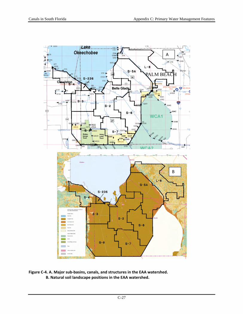
Canals in South Florida Appendix C: Primary Water Management Features
C-27
Figure C‐4. A. Major sub‐basins, canals, and structures in the EAA watershed. B. Natural soil landscape positions in the EAA watershed.
A
B
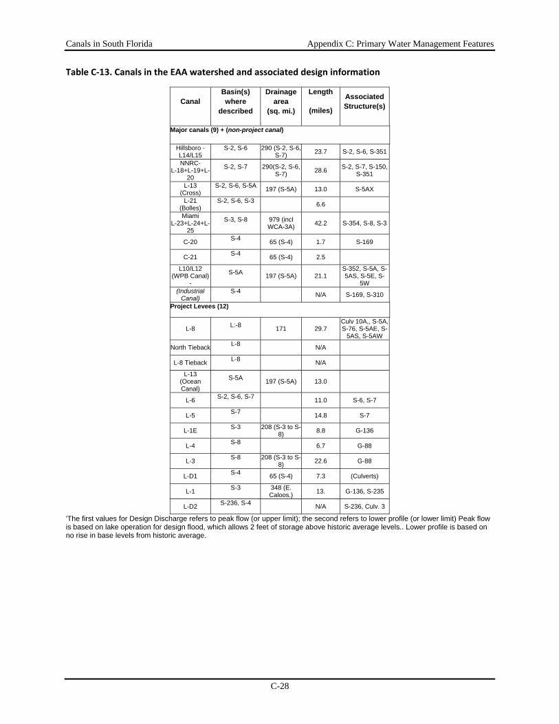
Canals in South Florida Appendix C: Primary Water Management Features
C-28
Table C‐13. Canals in the EAA watershed and associated design information
Canal Basin(s) where
described
Drainage area
(sq. mi.)
Length
(miles)
Associated Structure(s)
Major canals (9) + (non-project canal)
Hillsboro - L14/L15
S-2, S-6 290 (S-2, S-6, S-7) 23.7 S-2, S-6, S-351
NNRC- L-18+L-19+L-
20
S-2, S-7 290(S-2, S-6, S-7) 28.6 S-2, S-7, S-150,
S-351
L-13 (Cross)
S-2, S-6, S-5A 197 (S-5A) 13.0 S-5AX
L-21 (Bolles)
S-2, S-6, S-3 6.6
Miami L-23+L-24+L-
25
S-3, S-8 979 (incl WCA-3A) 42.2 S-354, S-8, S-3
C-20 S-4 65 (S-4) 1.7 S-169
C-21 S-4 65 (S-4) 2.5
L10/L12 (WPB Canal)
-
S-5A 197 (S-5A) 21.1 S-352, S-5A, S-5AS, S-5E, S-
5W (Industrial
Canal) S-4 N/A S-169, S-310
Project Levees (12)
L-8 L:-8 171 29.7 Culv 10A,, S-5A, S-76, S-5AE, S-
5AS, S-5AW
North Tieback L-8 N/A
L-8 Tieback L-8 N/A
L-13 (Ocean Canal)
S-5A 197 (S-5A) 13.0
L-6 S-2, S-6, S-7 11.0 S-6, S-7
L-5 S-7 14.8 S-7
L-1E S-3 208 (S-3 to S-8) 8.8 G-136
L-4 S-8 6.7 G-88
L-3 S-8 208 (S-3 to S-8) 22.6 G-88
L-D1 S-4 65 (S-4) 7.3 (Culverts)
L-1 S-3 348 (E. Caloos.) 13. G-136, S-235
L-D2 S-236, S-4 N/A S-236, Culv. 3
'The first values for Design Discharge refers to peak flow (or upper limit); the second refers to lower profile (or lower limit) Peak flow is based on lake operation for design flood, which allows 2 feet of storage above historic average levels.. Lower profile is based on no rise in base levels from historic average.
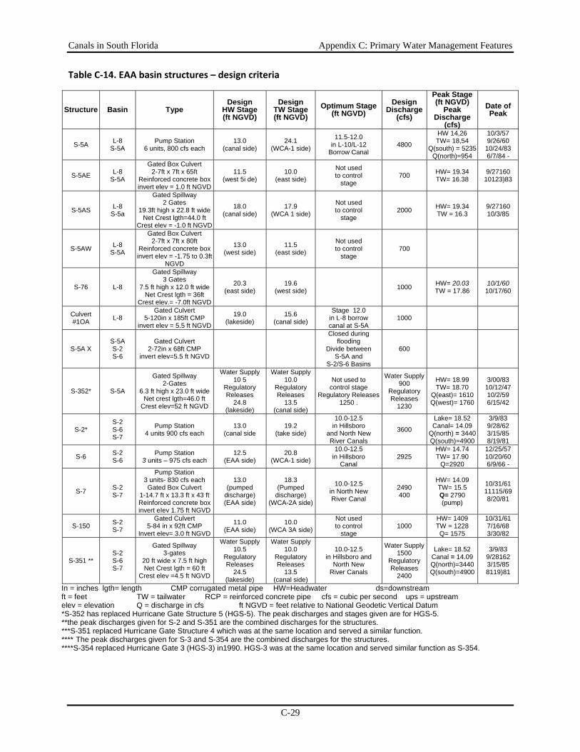
Canals in South Florida Appendix C: Primary Water Management Features
C-29
Table C‐14. EAA basin structures – design criteria
Structure Basin Type Design
HW Stage (ft NGVD)
Design TW Stage (ft NGVD)
Optimum Stage (ft NGVD)
Design Discharge
(cfs)
Peak Stage (ft NGVD)
Peak Discharge
(cfs)
Date of Peak
S-5A L-8 S-5A
Pump Station 6 units, 800 cfs each
13.0 (canal side)
24.1 (WCA-1 side)
11.5-12.0 in L-10/L-12
Borrow Canal 4800
HW 14,26 TW= 18,54
Q(south) = 5235 Q(north)=954
10/3/57 9/26/60
10/24/83 6/7/84 -
S-5AE L-8 S-5A
Gated Box Culvert 2-7ft x 7ft x 65ft
Reinforced concrete box invert elev = 1.0 ft NGVD
11.5 (west 5i de)
10.0 (east side)
Not used to control
stage 700 HW= 19.34
TW= 16.38 9/27160
10123)83
S-5AS L-8 S-5a
Gated Spillway 2 Gates
19.3ft high x 22.8 ft wide Net Crest lgth=44.0 ft
Crest elev = -1.0 ft NGVD
18.0 (canal side)
17.9 (WCA 1 side)
Not used to control
stage 2000 HW= 19.34
TW = 16.3 9/27160 10/3/85
S-5AW L-8 S-5A
Gated Box Culvert 2-7ft x 7ft x 80ft
Reinforced concrete box invert elev = -1.75 to 0.3ft
NGVD
13.0 (west side)
11.5 (east side)
Not used to control
stage 700
S-76 L-8
Gated Spillway 3 Gates
7.5 ft high x 12.0 ft wide Net Crest lgth = 36ft
Crest elev.= -7.0ft NGVD
20.3 (east side)
19.6 (west side) 1000 HW= 20.03
TW = 17.86 10/1/60
10/17/60
Culvert #1OA L-8
Gated Culvert 5-120in x 185ft CMP
invert elev = 5.5 ft NGVD
19.0 (lakeside)
15.6 (canal side)
Stage 12.0 in L-8 borrow canal at S-5A
1000
S-5A X S-5A S-2 S-6
Gated Culvert 2-72in x 68ft CMP
invert elev=5.5 ft NGVD
Closed during flooding
Divide between S-5A and
S-2/S-6 Basins
600
S-352* S-5A
Gated Spillway 2-Gates
6.3 ft high x 23.0 ft wide Net crest lgth=46.0 ft
Crest elev=52 ft NGVD
Water Supply 10 5
Regulatory Releases
24.8 (lakeside)
Water Supply 10.0
Regulatory Releases
13.5 (canal side)
Not used to control stage
Regulatory Releases 1250 .
Water Supply 900
Regulatory Releases
1230
HW= 18.99 TW= 18.70
Q(east)= 1610 Q(west)= 1760
3/00/83 10/12/47 10/2/59 6/15/42
S-2* S-2 S-6 S-7
Pump Station 4 units 900 cfs each
13.0 (canal side
19.2 (take side)
10.0-12.5 in Hillsboro
and North New River Canals
3600
Lake= 18.52 Canal= 14.09
Q(north) = 3440 Q(south)=4900
3/9/83 9/28/62 3/15/85 8/19/81
S-6 S-2 S-6
Pump Station 3 units – 975 cfs each
12.5 (EAA side)
20.8 (WCA-1 side)
10.0-12.5 in Hillsboro
Canal 2925
HW= 14.74 TW= 17.90
Q=2920
12/25/57 10/20/60 6/9/66 -
S-7 S-2 S-7
Pump Station 3 units- 830 cfs each Gated Box Culvert
1-14.7 ft x 13.3 ft x 43 ft Reinforced concrete box invert eIev 1.75 ft NGVD
13.0 (pumped
discharge) (EAA side)
18.3 (Pumped
discharge) (WCA-2A side)
10.0-12.5 in North New River Canal
2490 400
HW= 14.09 TW= 15.5 Q= 2790 (pump)
10/31/61 11115/69 8/20/81
S-150 S-2 S-7
Gated Culvert 5-84 in x 92ft CMP
Invert elev= 3.0 ft NGVD
11.0 (EAA side)
10.0 (WCA 3A side)
Not used to control
stage 1000
HW= 1409 TW = 1228 Q= 1575
10/31/61 7/16/68 3/30/82
S-351 ** S-2 S-6 S-7
Gated Spillway 3-gates
20 ft wide x 7.5 ft high Net Crest lgth = 60 ft
Crest elev =4.5 ft NGVD
Water Supply 10.5
Regulatory Releases
24.5 (lakeside)
Water Supply 10.0
Regulatory Releases
13.5 (canal side)
10.0-12.5 in Hillsboro and
North New River Canals
Water Supply 1500
Regulatory Releases
2400
Lake= 18.52 Canal = 14.09 Q(north)=3440 Q(south)=4900
3/9/83 9/28162 3/15/85 8119)81
In = inches lgth= length CMP corrugated metal pipe HW=Headwater ds=downstream ft = feet TW = tailwater RCP = reinforced concrete pipe cfs = cubic per second ups = upstream elev = elevation Q = discharge in cfs ft NGVD = feet relative to National Geodetic Vertical Datum *S-352 has replaced Hurricane Gate Structure 5 (HGS-5). The peak discharges and stages given are for HGS-5. **the peak discharges given for S-2 and S-351 are the combined discharges for the structures. ***S-351 replaced Hurricane Gate Structure 4 which was at the same location and served a similar function. **** The peak discharges given for S-3 and S-354 are the combined discharges for the structures. ****S-354 replaced Hurricane Gate 3 (HGS-3) in1990. HGS-3 was at the same location and served similar function as S-354.
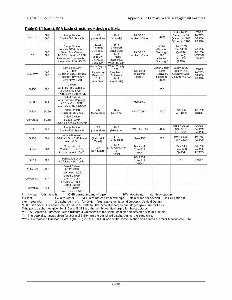
Canals in South Florida Appendix C: Primary Water Management Features
C-30
Table C‐14 (cont). EAA basin structures – design criteria
S-3**** S-3 S-8
Pump Station 3 units-890 cfs each
13.0 (canal side)
19.4 (lakeside)
10.0-12.5 in Miami Canal 2580
Lake 18.38 Canal = 14.92
Q(north) = 2280 Q(south)= 2790
3/9/83 10/2/65 3/24/66 3/26/70
S-8 S-3 S-8
Pump Station 4 units – 1040 cfs each
Gated Box Culvert 1-16.5ft x 14.0ft x 78.5ft Reinforced Concrete box Invert elev=1.0ft NGVD
12.13 (Pumped
Discharge) 12.0
(Gravity Discharge)(EAA side)
16.5 (Pumped
Discharge) 11.0
(Gravity Discharge)
(WCA-3A side)
10.0-12.5 in Miami Canal
4170 (Pumped
Discharge) 500
(Gravity Discharge)
HW 13.05 TW 14.69 Q=4240 (pump)
Q= 1252 (SPW)
2/15/66 7/11/56
10/22/69 1/18177
S-354**** S-3 S-8
Gated Spillway 2-Gates
8.3 ft high x 23.0 ft wide Net crest lgth=46.0 ft
Crest elev= 3.2 ft
Water Supply 10.5
Regulatory Releases
24.8 (lake Side)
Water Supply 100
Regulatory Releases
24.8 (canal side)
Not used to control
stage
Water Supply 1450
Regulatory Releases
2000
Lake= 18.38 Canal= 1432
Q(north)=2280 Q(south) = 2790
.
3/9/83 10/2/65 3/24/66 3/26/70
G-136 S-3
Culvert with riser and stop logs
3-84 in x 80 ft CMP invert elev= 8.0 ft NGVD
850
G-88 S-8
Gated Culvert with riser and stop logs
4-72 in x91 ft CMP Invert elev= 6.- ft NGVD
HW≤15.0
S-236 S-236 Pump Station 3 units-85 cfs each
7.5 (canal side)
18.5 (lakeside HW=7.5-9.7 255 HW=10.80
TW= 18.22 12/1/80 3/3183
Culvert #3 S-236 Galed Culvert 2-120 in CMP
Invert elev. = 5.5 ft NGVD
S-4 S-4 Pump Station 3 units-935 cfs each
13.0 (canal side)
19.2 (lake side) HW= 11.0-14.0 2805
Lake = 18.22 Canal = 14.3
Q = 1764
3/3/53 6/28/79 8/28/88
S-169 S-4 - Gated Culvert
3-84 in x 60 ft CMP Invert elev= 6.Oft
15.0 (Industrial
Canal)
14.1 (C-21 side) HW= 150 625 HW= 16.10
TW = 14.25 10/7/88 7/12/88
S-235 S-4 Gated culvert
2-72 in x 70 in RCP invert eIev=4ft NGVD
13.0 (S-4 Basin)
12.5 (Caloosahatche
e River)
Not used to control
stage
HW = 14.7 TW= 12.8
Q=584
5/21/80 9/23/78 12/8/85
S-310 S-4 Navigation Lock 60 ft long x 50 ft wide
Not used to control
stage 510 8/4/87
Culvert#1 S-4 Gated Culvert 2-120” CMP
invert elev=5.5 ft
Culvert #1A S-4 Gated Culvert 3-84 in CMP
invert elev = 5.5 ft
Culvert #2 S-4 Gated Culvert 2-120” CMP
invert elev = 5.5 Ft .
In = inches lgth= length CMP corrugated metal pipe HW=Headwater ds=downstream ft = feet TW = tailwater RCP = reinforced concrete pipe cfs = cubic per second ups = upstream elev = elevation Q discharge in cfs ft NGVD = feet relative to National Geodetic Vertical Datum *S-352 replaced Hurricane Gate Structure 5 (HGS-5). The peak discharges and stages given are for HGS-5. **the peak discharges given for S-2 and S-351 are the combined discharges for the structures. ***S-351 replaced Hurricane Gate Structure 4 which was at the same location and served a similar function. **** The peak discharges given for S-3 and S-354 are the combined discharges for the structures. ****S-354 replaced Hurricane Gate 3 (HGS-3) in 1990. HCS-3 was at the same location and served a similar function as S-354.
Canals in South Florida Appendix C: Primary Water Management Features
C-31
Upper East Coast Watershed
Primary Canals that Discharge to Coastal Waters Nine basins are described in the Upper East Coast area (Figure C-5): the C-23, C-59, S-153, S-135, C-44, Tidal St. Lucie River, North Fork St. Lucie River, C-25, and C-24 basins. The primary function of C&SF Project canals in Martin and St. Lucie counties is to provide flood protection. Secondary uses of the canals include land drainage for agriculture and urban or residential development and regulation of groundwater levels to prevent intrusion of saltwater into local aquifers. Most canals supply water for irrigation during periods of low natural flow.
C-23 Canal The C-23 canal basin is approximately 167.7 square miles in area and is located in southwest St. Lucie County, eastern Okeechobee County , and northern Martin County. General features of C-23 and the other primary canals in the Upper East Coast are described in Table C-15 and structures are described in Table C-16. Flow in C-23 is divided between the C-23 and C-24 basins by the G-78 structure. The S-97 spillway located at the Florida's Turnpike crossing of the C-23 canal controls water surface elevations in the upper reach of C-23 and regulates discharge to the lower reach. S-48 controls stages in the lower reaches and outflow from C-23. In general the only water supply to the C-23 basin is from local rainfall and from pumping of groundwater from the Floridan Aquifer. Excess water is discharged to tidewater in the North Fork of the St. Lucie Estuary. A portion of C-23 extends into the C-24 basin. C-23 extends two miles to the west from its confluence with C-24 and then three miles south to G-78. Water surface elevations in this section of the canal are maintained at a higher level than in C-24. G-79 controls water surface elevations in this section. Flow of water in this part of C-23 is to the north to C-24.
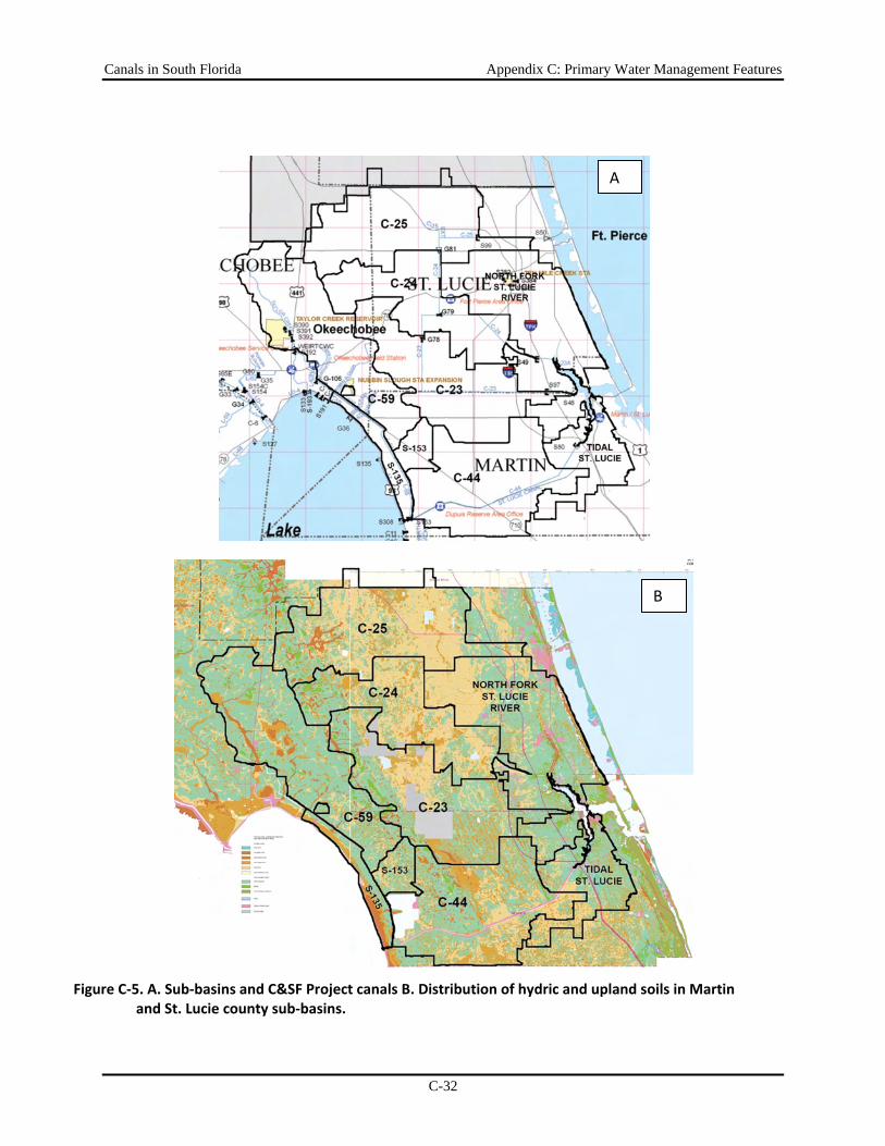
Canals in South Florida Appendix C: Primary Water Management Features
C-32
A
B
Figure C‐5. A. Sub‐basins and C&SF Project canals B. Distribution of hydric and upland soils in Martin and St. Lucie county sub‐basins.
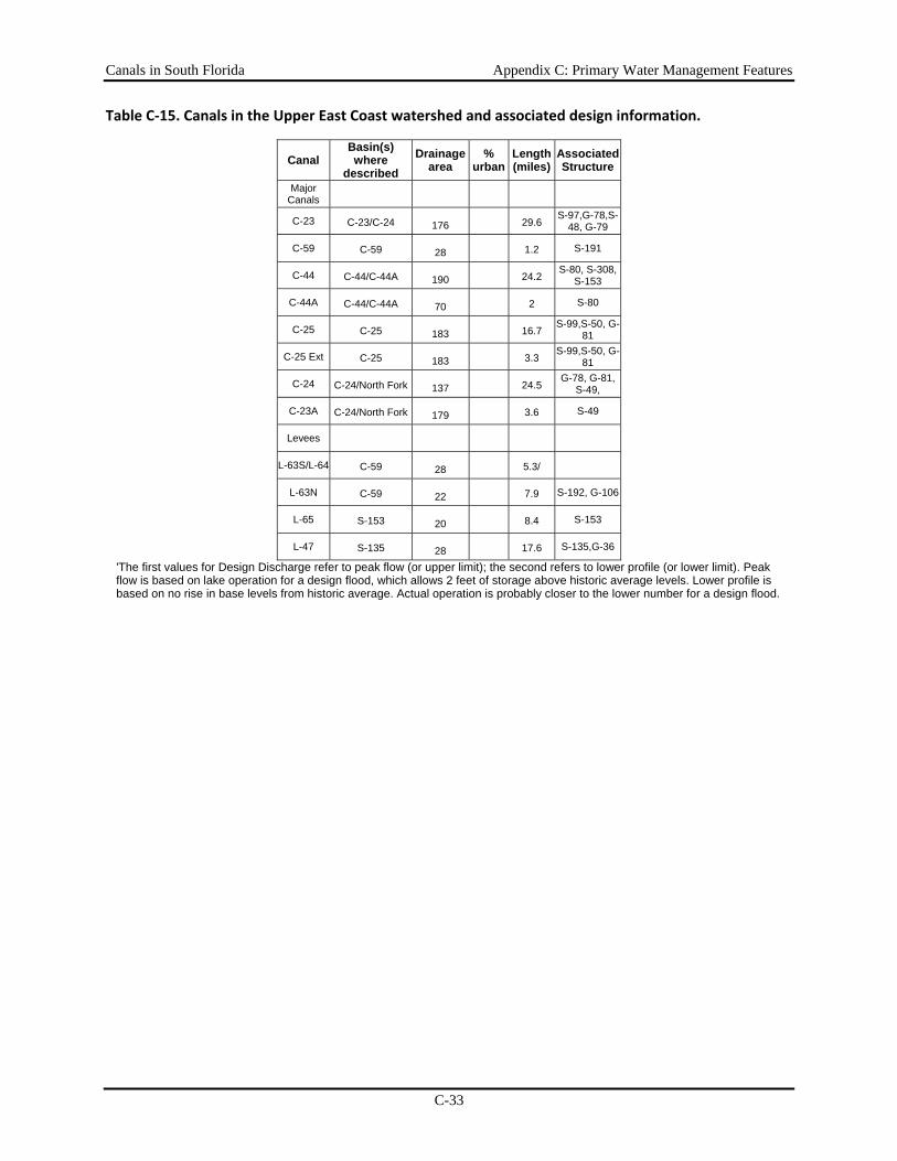
Canals in South Florida Appendix C: Primary Water Management Features
C-33
Table C‐15. Canals in the Upper East Coast watershed and associated design information.
Canal Basin(s) where
described Drainage
area %
urbanLength(miles)
Associated Structure
Major Canals
C-23 C-23/C-24 176 29.6
S-97,G-78,S-48, G-79
C-59 C-59 28 1.2 S-191
C-44 C-44/C-44A 190 24.2
S-80, S-308, S-153
C-44A C-44/C-44A 70 2 S-80
C-25 C-25 183 16.7
S-99,S-50, G-81
C-25 Ext C-25 183 3.3
S-99,S-50, G-81
C-24 C-24/North Fork 137 24.5
G-78, G-81, S-49,
C-23A C-24/North Fork 179 3.6 S-49
Levees
L-63S/L-64 C-59 28 5.3/
L-63N C-59 22 7.9 S-192, G-106
L-65 S-153 20 8.4 S-153
L-47 S-135 28 17.6 S-135,G-36
'The first values for Design Discharge refer to peak flow (or upper limit); the second refers to lower profile (or lower limit). Peak flow is based on lake operation for a design flood, which allows 2 feet of storage above historic average levels. Lower profile is based on no rise in base levels from historic average. Actual operation is probably closer to the lower number for a design flood.
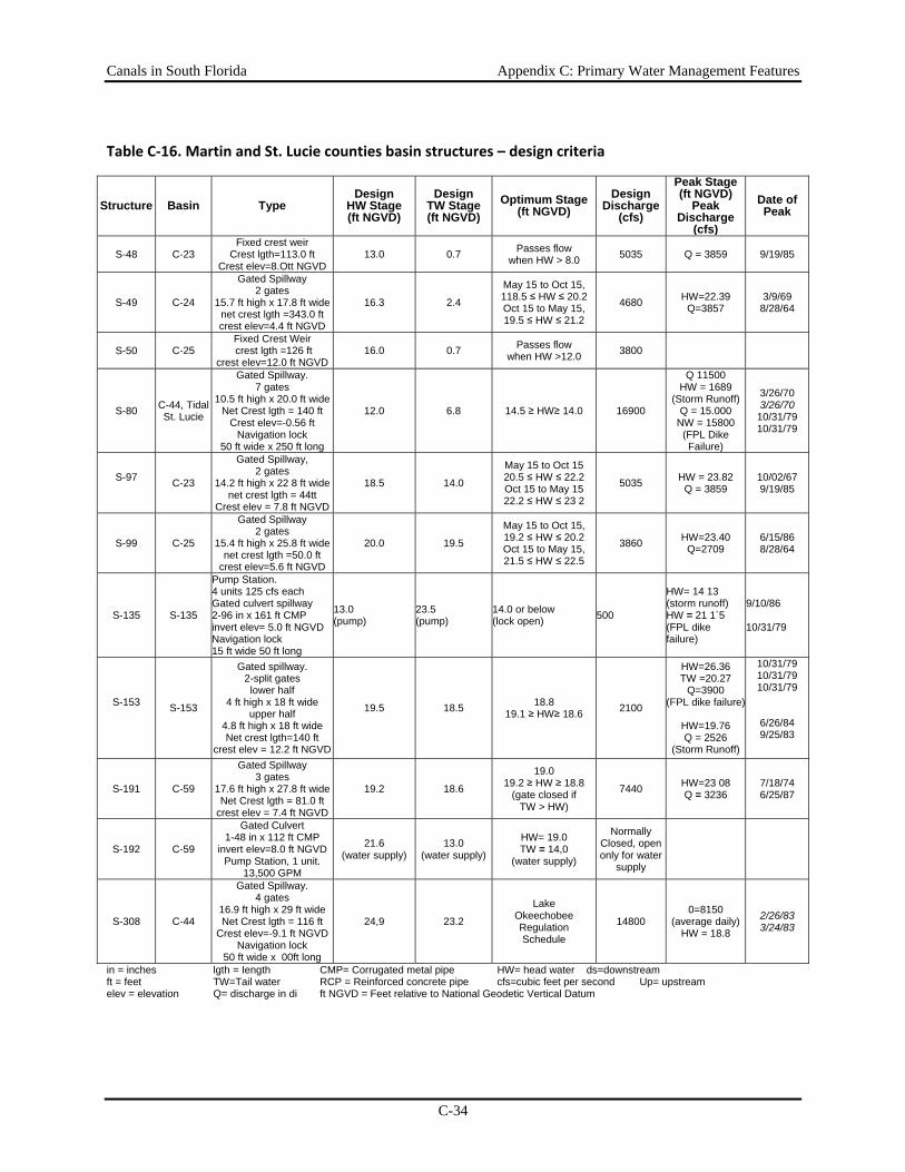
Canals in South Florida Appendix C: Primary Water Management Features
C-34
Table C‐16. Martin and St. Lucie counties basin structures – design criteria
Structure Basin Type Design
HW Stage (ft NGVD)
Design TW Stage (ft NGVD)
Optimum Stage (ft NGVD)
Design Discharge
(cfs)
Peak Stage (ft NGVD)
Peak Discharge
(cfs)
Date of Peak
S-48 C-23 Fixed crest weir
Crest lgth=113.0 ft Crest elev=8.Ott NGVD
13.0 0.7 Passes flow when HW > 8.0 5035 Q = 3859 9/19/85
S-49 C-24
Gated Spillway 2 gates
15.7 ft high x 17.8 ft wide net crest lgth =343.0 ft crest elev=4.4 ft NGVD
16.3 2.4
May 15 to Oct 15,118.5 ≤ HW ≤ 20.2Oct 15 to May 15, 19.5 ≤ HW ≤ 21.2
4680 HW=22.39 Q=3857
3/9/69 8/28/64
S-50 C-25 Fixed Crest Weir crest lgth =126 ft
crest elev=12.0 ft NGVD 16.0 0.7 Passes flow
when HW >12.0 3800
S-80 C-44, Tidal St. Lucie
Gated Spillway. 7 gates
10.5 ft high x 20.0 ft wide Net Crest lgth = 140 ft
Crest elev=-0.56 ft Navigation lock
50 ft wide x 250 ft long
12.0 6.8 14.5 ≥ HW≥ 14.0 16900
Q 11500 HW = 1689
(Storm Runoff) Q = 15.000
NW = 15800 (FPL Dike Failure)
3/26/70 3/26/70
10/31/79 10/31/79
S-97 C-23
Gated Spillway, 2 gates
14.2 ft high x 22 8 ft wide net crest lgth = 44tt
Crest elev = 7.8 ft NGVD
18.5 14.0
May 15 to Oct 15 20.5 ≤ HW ≤ 22.2 Oct 15 to May 15 22.2 ≤ HW ≤ 23 2
5035 HW = 23.82 Q = 3859
10/02/67 9/19/85
S-99 C-25
Gated Spillway 2 gates
15.4 ft high x 25.8 ft wide net crest lgth =50.0 ft
crest elev=5.6 ft NGVD
20.0 19.5
May 15 to Oct 15,19.2 ≤ HW ≤ 20.2Oct 15 to May 15, 21.5 ≤ HW ≤ 22.5
3860 HW=23.40 Q=2709
6/15/86 8/28/64
S-135 S-135
Pump Station. 4 units 125 cfs each Gated culvert spillway 2-96 in x 161 ft CMP invert elev= 5.0 ft NGVD Navigation lock 15 ft wide 50 ft long
13.0 (pump)
23.5 (pump)
14.0 or below (lock open) 500
HW= 14 13 (storm runoff) HW = 21 1`5 (FPL dike failure)
9/10/86 10/31/79
S-153 S-153
Gated spillway. 2-split gates lower half
4 ft high x 18 ft wide upper half
4.8 ft high x 18 ft wide Net crest lgth=140 ft
crest elev = 12.2 ft NGVD
19.5 18.5 18.8 19.1 ≥ HW≥ 18.6 2100
HW=26.36 TW =20.27
Q=3900 (FPL dike failure)
HW=19.76 Q = 2526
(Storm Runoff)
10/31/79 10/31/79 10/31/79
6/26/84 9/25/83
S-191 C-59
Gated Spillway 3 gates
17.6 ft high x 27.8 ft wide Net Crest lgth = 81.0 ft
crest elev = 7.4 ft NGVD
19.2 18.6
19.0 19.2 ≥ HW ≥ 18.8
(gate closed if TW > HW)
7440 HW=23 08 Q = 3236
7/18/74 6/25/87
S-192 C-59
Gated Culvert 1-48 in x 112 ft CMP
invert elev=8.0 ft NGVD Pump Station, 1 unit.
13,500 GPM
21.6 (water supply)
13.0 (water supply)
HW= 19.0 TW = 14,0
(water supply)
Normally Closed, open only for water
supply
S-308 C-44
Gated Spillway. 4 gates
16.9 ft high x 29 ft wide Net Crest lgth = 116 ft
Crest elev=-9.1 ft NGVD Navigation lock
50 ft wide x 00ft long
24,9 23.2
Lake Okeechobee Regulation Schedule
14800 0=8150
(average daily)HW = 18.8
2/26/83 3/24/83
in = inches lgth = Iength CMP= Corrugated metal pipe HW= head water ds=downstream ft = feet TW=Tail water RCP = Reinforced concrete pipe cfs=cubic feet per second Up= upstream elev = elevation Q= discharge in di ft NGVD = Feet relative to National Geodetic Vertical Datum
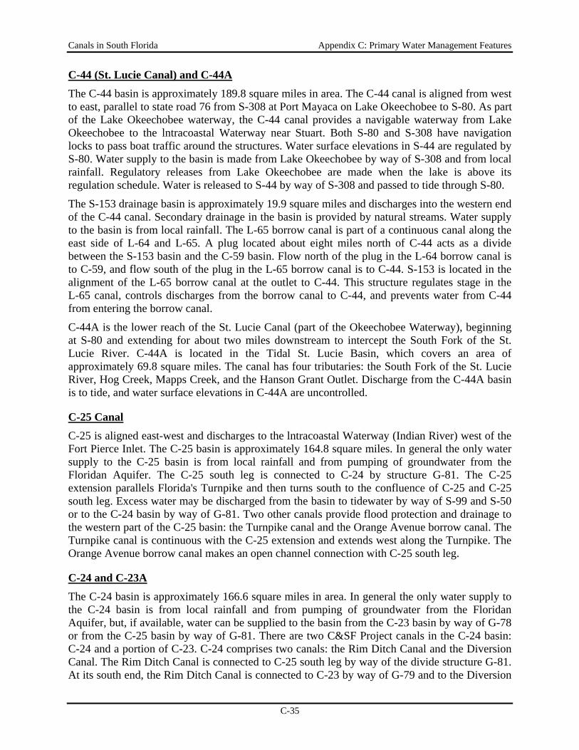
Canals in South Florida Appendix C: Primary Water Management Features
C-35
C-44 (St. Lucie Canal) and C-44A The C-44 basin is approximately 189.8 square miles in area. The C-44 canal is aligned from west to east, parallel to state road 76 from S-308 at Port Mayaca on Lake Okeechobee to S-80. As part of the Lake Okeechobee waterway, the C-44 canal provides a navigable waterway from Lake Okeechobee to the lntracoastal Waterway near Stuart. Both S-80 and S-308 have navigation locks to pass boat traffic around the structures. Water surface elevations in S-44 are regulated by S-80. Water supply to the basin is made from Lake Okeechobee by way of S-308 and from local rainfall. Regulatory releases from Lake Okeechobee are made when the lake is above its regulation schedule. Water is released to S-44 by way of S-308 and passed to tide through S-80.
The S-153 drainage basin is approximately 19.9 square miles and discharges into the western end of the C-44 canal. Secondary drainage in the basin is provided by natural streams. Water supply to the basin is from local rainfall. The L-65 borrow canal is part of a continuous canal along the east side of L-64 and L-65. A plug located about eight miles north of C-44 acts as a divide between the S-153 basin and the C-59 basin. Flow north of the plug in the L-64 borrow canal is to C-59, and flow south of the plug in the L-65 borrow canal is to C-44. S-153 is located in the alignment of the L-65 borrow canal at the outlet to C-44. This structure regulates stage in the L-65 canal, controls discharges from the borrow canal to C-44, and prevents water from C-44 from entering the borrow canal.
C-44A is the lower reach of the St. Lucie Canal (part of the Okeechobee Waterway), beginning at S-80 and extending for about two miles downstream to intercept the South Fork of the St. Lucie River. C-44A is located in the Tidal St. Lucie Basin, which covers an area of approximately 69.8 square miles. The canal has four tributaries: the South Fork of the St. Lucie River, Hog Creek, Mapps Creek, and the Hanson Grant Outlet. Discharge from the C-44A basin is to tide, and water surface elevations in C-44A are uncontrolled.
C-25 Canal
C-25 is aligned east-west and discharges to the lntracoastal Waterway (Indian River) west of the Fort Pierce Inlet. The C-25 basin is approximately 164.8 square miles. In general the only water supply to the C-25 basin is from local rainfall and from pumping of groundwater from the Floridan Aquifer. The C-25 south leg is connected to C-24 by structure G-81. The C-25 extension parallels Florida's Turnpike and then turns south to the confluence of C-25 and C-25 south leg. Excess water may be discharged from the basin to tidewater by way of S-99 and S-50 or to the C-24 basin by way of G-81. Two other canals provide flood protection and drainage to the western part of the C-25 basin: the Turnpike canal and the Orange Avenue borrow canal. The Turnpike canal is continuous with the C-25 extension and extends west along the Turnpike. The Orange Avenue borrow canal makes an open channel connection with C-25 south leg.
C-24 and C-23A The C-24 basin is approximately 166.6 square miles in area. In general the only water supply to the C-24 basin is from local rainfall and from pumping of groundwater from the Floridan Aquifer, but, if available, water can be supplied to the basin from the C-23 basin by way of G-78 or from the C-25 basin by way of G-81. There are two C&SF Project canals in the C-24 basin: C-24 and a portion of C-23. C-24 comprises two canals: the Rim Ditch Canal and the Diversion Canal. The Rim Ditch Canal is connected to C-25 south leg by way of the divide structure G-81. At its south end, the Rim Ditch Canal is connected to C-23 by way of G-79 and to the Diversion
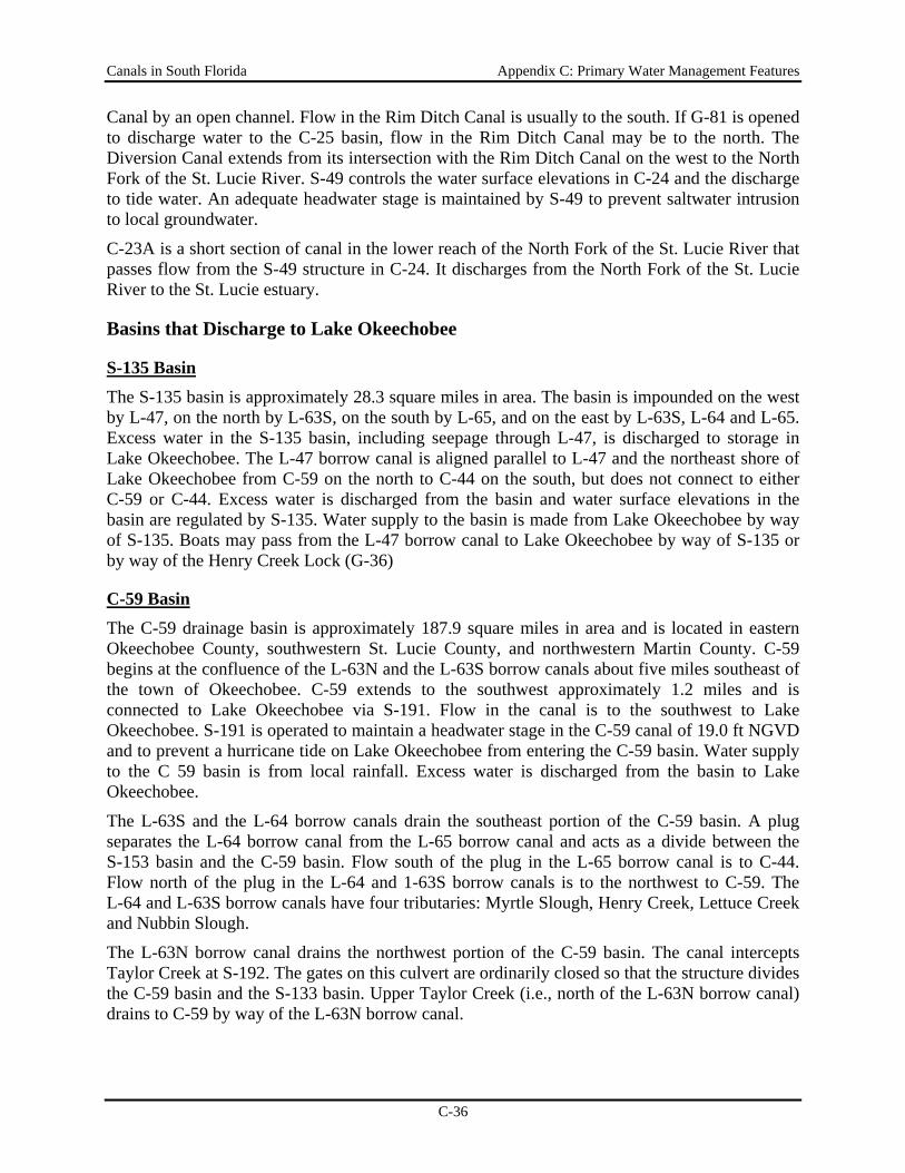
Canals in South Florida Appendix C: Primary Water Management Features
C-36
Canal by an open channel. Flow in the Rim Ditch Canal is usually to the south. If G-81 is opened to discharge water to the C-25 basin, flow in the Rim Ditch Canal may be to the north. The Diversion Canal extends from its intersection with the Rim Ditch Canal on the west to the North Fork of the St. Lucie River. S-49 controls the water surface elevations in C-24 and the discharge to tide water. An adequate headwater stage is maintained by S-49 to prevent saltwater intrusion to local groundwater.
C-23A is a short section of canal in the lower reach of the North Fork of the St. Lucie River that passes flow from the S-49 structure in C-24. It discharges from the North Fork of the St. Lucie River to the St. Lucie estuary.
Basins that Discharge to Lake Okeechobee
S-135 Basin The S-135 basin is approximately 28.3 square miles in area. The basin is impounded on the west by L-47, on the north by L-63S, on the south by L-65, and on the east by L-63S, L-64 and L-65. Excess water in the S-135 basin, including seepage through L-47, is discharged to storage in Lake Okeechobee. The L-47 borrow canal is aligned parallel to L-47 and the northeast shore of Lake Okeechobee from C-59 on the north to C-44 on the south, but does not connect to either C-59 or C-44. Excess water is discharged from the basin and water surface elevations in the basin are regulated by S-135. Water supply to the basin is made from Lake Okeechobee by way of S-135. Boats may pass from the L-47 borrow canal to Lake Okeechobee by way of S-135 or by way of the Henry Creek Lock (G-36)
C-59 Basin The C-59 drainage basin is approximately 187.9 square miles in area and is located in eastern Okeechobee County, southwestern St. Lucie County, and northwestern Martin County. C-59 begins at the confluence of the L-63N and the L-63S borrow canals about five miles southeast of the town of Okeechobee. C-59 extends to the southwest approximately 1.2 miles and is connected to Lake Okeechobee via S-191. Flow in the canal is to the southwest to Lake Okeechobee. S-191 is operated to maintain a headwater stage in the C-59 canal of 19.0 ft NGVD and to prevent a hurricane tide on Lake Okeechobee from entering the C-59 basin. Water supply to the C 59 basin is from local rainfall. Excess water is discharged from the basin to Lake Okeechobee.
The L-63S and the L-64 borrow canals drain the southeast portion of the C-59 basin. A plug separates the L-64 borrow canal from the L-65 borrow canal and acts as a divide between the S-153 basin and the C-59 basin. Flow south of the plug in the L-65 borrow canal is to C-44. Flow north of the plug in the L-64 and 1-63S borrow canals is to the northwest to C-59. The L-64 and L-63S borrow canals have four tributaries: Myrtle Slough, Henry Creek, Lettuce Creek and Nubbin Slough.
The L-63N borrow canal drains the northwest portion of the C-59 basin. The canal intercepts Taylor Creek at S-192. The gates on this culvert are ordinarily closed so that the structure divides the C-59 basin and the S-133 basin. Upper Taylor Creek (i.e., north of the L-63N borrow canal) drains to C-59 by way of the L-63N borrow canal.
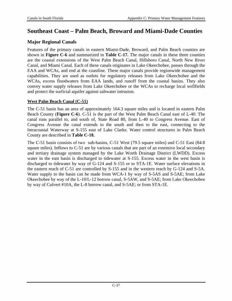
Canals in South Florida Appendix C: Primary Water Management Features
C-37
Southeast Coast – Palm Beach, Broward and Miami-Dade Counties
Major Regional Canals Features of the primary canals in eastern Miami-Dade, Broward, and Palm Beach counties are shown in Figure C-6 and summarized in Table C-17. The major canals in these three counties are the coastal extensions of the West Palm Beach Canal, Hillsboro Canal, North New River Canal, and Miami Canal. Each of these canals originates in Lake Okeechobee, passes through the EAA and WCAs, and end at the coastline. These major canals provide regionwide management capabilities. They are used as outlets for regulatory releases from Lake Okeechobee and the WCAs, excess floodwaters from EAA lands, and runoff from the coastal basins. They also convey water supply releases from Lake Okeechobee or the WCAs to recharge local wellfields and protect the surficial aquifer against saltwater intrusion.
West Palm Beach Canal (C-51) The C-51 basin has an area of approximately 164.3 square miles and is located in eastern Palm Beach County (Figure C-6). C-51 is the part of the West Palm Beach Canal east of L-40. The canal runs parallel to, and south of, State Road 80, from L-40 to Congress Avenue. East of Congress Avenue the canal extends to the south and then to the east, connecting to the lntracoastal Waterway at S-155 east of Lake Clarke. Water control structures in Palm Beach County are described in Table C-18.
The C-51 basin consists of two sub-basins, C-51 West (79.5 square miles) and C-51 East (84.8 square miles). Inflows to C-51 are by various canals that are part of an extensive local secondary and tertiary drainage system managed by the Lake Worth Drainage District (LWDD). Excess water in the east basin is discharged to tidewater at S-155. Excess water in the west basin is discharged to tidewater by way of G-124 and S-155 or to STA-1E. Water surface elevations in the eastern reach of C-51 are controlled by S-155 and in the western reach by G-124 and S-5A. Water supply to the basin can be made from WCA-1 by way of S-5AS and S-5AE; from Lake Okeechobee by way of the L-10/L-12 borrow canal, S-5AW, and S-5AE; from Lake Okeechobee by way of Culvert #10A, the L-8 borrow canal, and S-5AE; or from STA-1E.

Canals in South Florida Appendix C: Primary Water Management Features
C-38
Figure C‐6. A) SFWMD canals and structures, and B) natural landscape soil positions in coastal sub‐basins of Miami‐Dade, Broward, and Palm Beach counties (based on Zahina et al. 2001).
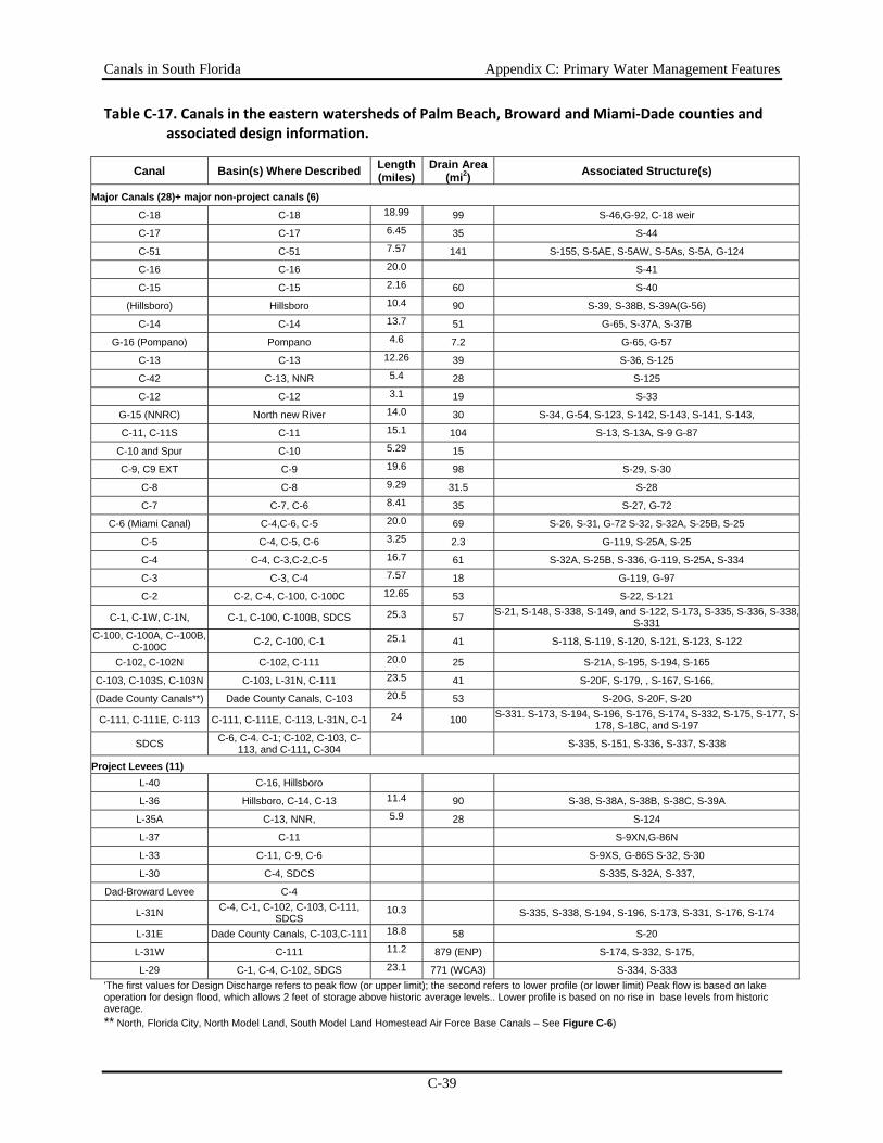
Canals in South Florida Appendix C: Primary Water Management Features
C-39
Table C‐17. Canals in the eastern watersheds of Palm Beach, Broward and Miami‐Dade counties and associated design information.
Canal Basin(s) Where Described Length (miles)
Drain Area(mi2) Associated Structure(s)
Major Canals (28)+ major non-project canals (6) C-18 C-18 18.99 99 S-46,G-92, C-18 weir
C-17 C-17 6.45 35 S-44
C-51 C-51 7.57 141 S-155, S-5AE, S-5AW, S-5As, S-5A, G-124
C-16 C-16 20.0 S-41
C-15 C-15 2.16 60 S-40
(Hillsboro) Hillsboro 10.4 90 S-39, S-38B, S-39A(G-56)
C-14 C-14 13.7 51 G-65, S-37A, S-37B
G-16 (Pompano) Pompano 4.6 7.2 G-65, G-57
C-13 C-13 12.26 39 S-36, S-125
C-42 C-13, NNR 5.4 28 S-125
C-12 C-12 3.1 19 S-33
G-15 (NNRC) North new River 14.0 30 S-34, G-54, S-123, S-142, S-143, S-141, S-143,
C-11, C-11S C-11 15.1 104 S-13, S-13A, S-9 G-87
C-10 and Spur C-10 5.29 15
C-9, C9 EXT C-9 19.6 98 S-29, S-30
C-8 C-8 9.29 31.5 S-28
C-7 C-7, C-6 8.41 35 S-27, G-72
C-6 (Miami Canal) C-4,C-6, C-5 20.0 69 S-26, S-31, G-72 S-32, S-32A, S-25B, S-25
C-5 C-4, C-5, C-6 3.25 2.3 G-119, S-25A, S-25
C-4 C-4, C-3,C-2,C-5 16.7 61 S-32A, S-25B, S-336, G-119, S-25A, S-334
C-3 C-3, C-4 7.57 18 G-119, G-97
C-2 C-2, C-4, C-100, C-100C 12.65 53 S-22, S-121
C-1, C-1W, C-1N, C-1, C-100, C-100B, SDCS 25.3 57 S-21, S-148, S-338, S-149, and S-122, S-173, S-335, S-336, S-338, S-331
C-100, C-100A, C--100B, C-100C C-2, C-100, C-1 25.1 41 S-118, S-119, S-120, S-121, S-123, S-122
C-102, C-102N C-102, C-111 20.0 25 S-21A, S-195, S-194, S-165
C-103, C-103S, C-103N C-103, L-31N, C-111 23.5 41 S-20F, S-179, , S-167, S-166,
(Dade County Canals**) Dade County Canals, C-103 20.5 53 S-20G, S-20F, S-20
C-111, C-111E, C-113 C-111, C-111E, C-113, L-31N, C-1 24 100 S-331. S-173, S-194, S-196, S-176, S-174, S-332, S-175, S-177, S-178, S-18C, and S-197
SDCS C-6, C-4. C-1; C-102, C-103, C-113, and C-111, C-304
S-335, S-151, S-336, S-337, S-338
Project Levees (11) L-40 C-16, Hillsboro
L-36 Hillsboro, C-14, C-13 11.4 90 S-38, S-38A, S-38B, S-38C, S-39A
L-35A C-13, NNR, 5.9 28 S-124
L-37 C-11 S-9XN,G-86N
L-33 C-11, C-9, C-6 S-9XS, G-86S S-32, S-30
L-30 C-4, SDCS S-335, S-32A, S-337,
Dad-Broward Levee C-4
L-31N C-4, C-1, C-102, C-103, C-111, SDCS
10.3 S-335, S-338, S-194, S-196, S-173, S-331, S-176, S-174
L-31E Dade County Canals, C-103,C-111 18.8 58 S-20
L-31W C-111 11.2 879 (ENP) S-174, S-332, S-175,
L-29 C-1, C-4, C-102, SDCS 23.1 771 (WCA3) S-334, S-333 'The first values for Design Discharge refers to peak flow (or upper limit); the second refers to lower profile (or lower limit) Peak flow is based on lake operation for design flood, which allows 2 feet of storage above historic average levels.. Lower profile is based on no rise in base levels from historic average. ** North, Florida City, North Model Land, South Model Land Homestead Air Force Base Canals – See Figure C-6)
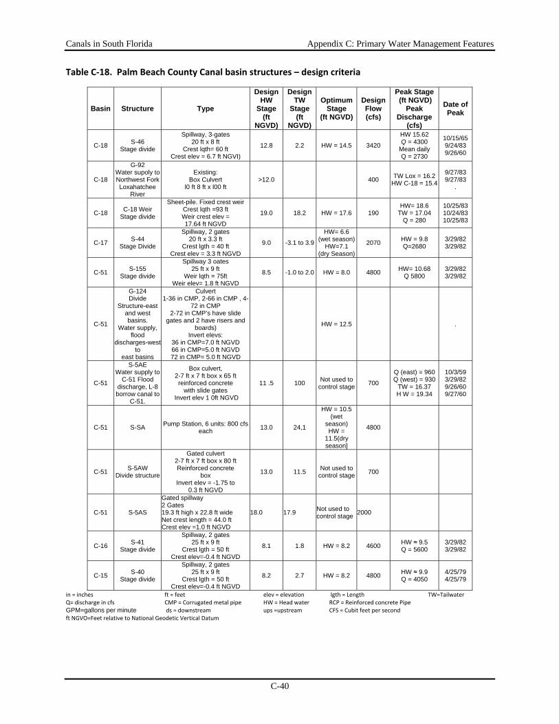
Canals in South Florida Appendix C: Primary Water Management Features
C-40
Table C‐18. Palm Beach County Canal basin structures – design criteria
Basin Structure Type
Design HW
Stage (ft
NGVD)
Design TW
Stage(ft
NGVD)
Optimum Stage
(ft NGVD)
Design Flow (cfs)
Peak Stage (ft NGVD)
Peak Discharge
(cfs)
Date of Peak
C-18 S-46 Stage divide
Spillway, 3-gates 20 ft x 8 ft
Crest lqth= 60 ft Crest elev = 6.7 ft NGVI)
12.8 2.2 HW = 14.5 3420
HW 15.62 Q = 4300
Mean daily Q = 2730
10/15/65 9/24/83 9/26/60
C-18
G-92 Water supoly to Northwest Fork Loxahatchee
River
Existing: Box Culvert
l0 ft 8 ft x l00 ft >12.0 400 TW Lox = 16.2
HW C-18 = 15.4
9/27/83 9/27/83
.
C-18 C-18 Weir Stage divide
Sheet-pile. Fixed crest weir Crest lqth =93 ft Weir crest elev = 17.64 ft NGVD
19.0 18.2 HW = 17.6 190 HW= 18.6
TW = 17.04 Q = 280
10/25/83 10/24/83 10/25/83
C-17 S-44 Stage Divide
Spillway, 2 gates 20 ft x 3.3 ft
Crest lgth = 40 ft Crest elev = 3.3 ft NGVD
9.0 -3.1 to 3.9
HW= 6.6 (wet season)
HW=7.1 (dry Season)
2070 HW = 9.8 Q=2680
3/29/82 3/29/82
C-51 S-155 Stage divide
Spillway 3 oates 25 ft x 9 ft
Weir lqth = 75ft Weir elev= 1.8 ft NGVD
8.5 -1.0 to 2.0 HW = 8.0 4800 HW= 10.68 Q 5800
3/29/82 3/29/82
C-51
G-124 Divide
Structure-east and west basins.
Water supply, flood
discharges-west to
east basins
Culvert 1-36 in CMP, 2-66 in CMP , 4-
72 in CMP 2-72 in CMP’s have slide
gates and 2 have risers and boards)
Invert elevs: 36 in CMP=7.0 ft NGVD 66 in CMP=5.0 ft NGVD 72 in CMP= 5.0 ft NGVD
HW = 12.5 .
C-51
S-5AE Water supply to
C-51 Flood discharge, L-8 borrow canal to
C-51.
Box culvert, 2-7 ft x 7 ft box x 65 ft reinforced concrete
with slide gates Invert elev 1 0ft NGVD
11 .5 100 Not used to control stage 700
Q (east) = 960 Q (west) = 930
TW = 16.37 H W = 19.34
10/3/59 3/29/82 9/26/60 9/27/60
C-51 S-SA Pump Station, 6 units: 800 cfseach 13.0 24,1
HW = 10.5 (wet
season) HW =
11.5(dry season]
4800
C-51 S-5AW Divide structure
Gated culvert 2-7 ft x 7 ft box x 80 ft Reinforced concrete
box Invert elev = -1.75 to
0.3 ft NGVD
13.0 11.5 Not used to control stage 700
C-51 S-5AS
Gated spillway 2 Gates 19.3 ft high x 22.8 ft wide Net crest length = 44.0 ft Crest elev =1.0 ft NGVD
18.0 17.9 Not used to control stage 2000
C-16 S-41 Stage divide
Spillway, 2 gates 25 ft x 9 ft
Crest lgth = 50 ft Crest elev=-0.4 ft NGVD
8.1 1.8 HW = 8.2 4600 HW ≈ 9.5 Q = 5600
3/29/82 3/29/82
C-15 S-40 Stage divide
Spillway, 2 gates 25 ft x 9 ft
Crest lgth = 50 ft Crest elev=-0.4 ft NGVD
8.2 2.7 HW = 8.2 4800 HW ≈ 9.9 Q = 4050
4/25/79 4/25/79
in = inches ft = feet elev = elevation lgth = Length TW=Tailwater Q= discharge in cfs CMP = Corrugated metal pipe HW = Head water RCP = Reinforced concrete Pipe GPM=gallons per minute ds = downstream ups =upstream CFS = Cubit feet per second ft NGVO=Feet relative to National Geodetic Vertical Datum
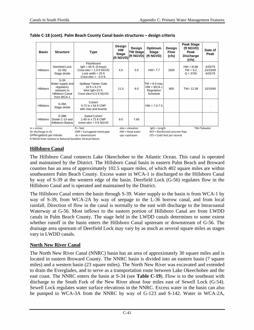
Canals in South Florida Appendix C: Primary Water Management Features
C-41
Table C‐18 (cont). Palm Beach County Canal basin structures – design criteria
Basin Structure Type Design
HW Stage
(ft NGVD)
Design TW Stage(ft NGVD)
Optimum Stage
(ft NGVD)
Design Flow (cfs)
Peak Stage (ft NGVD)
Peak Discharge
(cfs)
Date of Peak
Hillsboro Deerfield Lock
(G-56) Stage divide
Flashboard lgth = 65 ft. (5-bays)
Crest elev = 1.0 ft NGVD Lock width = 25 ft
Crest elev = -5.0 ft.
4.0 3.5 HW= 7.7 1600 HW = l0,86 TW = 9.2 Q = 3700
4/25/79 10/15/65 4/25/79
Hillsboro
S-39 Water supply and
regulatory releases to
Hillsboro Canal from WCA-1
Spillway Tainter Gate 16 ft x 9.2 ft
Weir lgth=15 ft. Crest elev=2.5 ft NGVD
11.0 9.0
TW = 9.0 max. HW = WCA 1
Regulation Schedule
800 TW= 12.39 10/15/65
Hillsboro S-39A Stage divide
Culvert 3-72 in x 54 ft CMP
with riser and boards HW = 7.0-7.5 .
Hillsboro S-38B
Divide C-14 and lHillsboro Basins
Gated Culvert 1-65 in x 72 ft CMP
Invert elev = 0 ft NGVD 9.0 7.65
in = inches ft = feet elev = elevation lgth = Length TW=Tailwater Q= discharge in cfs CMP = Corrugated metal pipe HW = Head water RCP = Reinforced concrete Pipe GPM=gallons per minute ds = downstream ups =upstream CFS = Cubit feet per second ft NGVO=Feet relative to National Geodetic Vertical Datum
Hillsboro Canal The Hillsboro Canal connects Lake Okeechobee to the Atlantic Ocean. This canal is operated and maintained by the District. The Hillsboro Canal basin in eastern Palm Beach and Broward counties has an area of approximately 102.5 square miles, of which 402 square miles are within southeastern Palm Beach County. Excess water in WCA-1 is discharged to the Hillsboro Canal by way of S-39 at the western edge of the basin. Deerfield Lock (G-56) regulates flow in the Hillsboro Canal and is operated and maintained by the District.
The Hillsboro Canal enters the basin through S-39. Water supply to the basin is from WCA-1 by way of S-39, from WCA-2A by way of seepage to the L-36 borrow canal, and from local rainfall. Direction of flow in the canal is normally to the east with discharge to the lntracoastal Waterway at G-56. Most inflows to the eastern portion of Hillsboro Canal are from LWDD canals in Palm Beach County. The stage held in the LWDD canals determines to some extent whether runoff in the basin enters the Hillsboro Canal upstream or downstream of G-56. The drainage area upstream of Deerfield Lock may vary by as much as several square miles as stages vary in LWDD canals.
North New River Canal
The North New River Canal (NNRC) basin has an area of approximately 30 square miles and is located in eastern Broward County. The NNRC basin is divided into an eastern basin (7 square miles) and a western basin (23 square miles). The North New River was excavated and extended to drain the Everglades, and to serve as a transportation route between Lake Okeechobee and the east coast. The NNRC enters the basin at S-34 (see Table C-19). Flow is to the southeast with discharge to the South Fork of the New River about four miles east of Sewell Lock (G-54). Sewell Lock regulates water surface elevations in the NNRC. Excess water in the basin can also be pumped to WCA-3A from the NNRC by way of G-123 and S-142. Water in WCA-2A,
Canals in South Florida Appendix C: Primary Water Management Features
C-42
WCA-2B, or WCA-3A is discharged to the NNRC by way of S-143, S-141, and S-142 respectively.
C-42 is the continuation of the L-36 borrow canal south of L-35A. The canal enters the NNRC basin at S-125 just south of C-13. Flow in the canal is to the south to the NNRC. S-125 usually divides flow in C-42 between the C-13 and the NNRC basins, but is occasionally used to discharge water from the C-13 basin to the NNRC basin for water supply.
Miami Canal (C-6) The C-6 basin has an area of approximately 69 square miles and is located in eastern Miami-Dade County (Figure C-6). C-6 begins at S-31 at the intersection of L-30 and L-33. The L-33 borrow canal is aligned north-south along the east boundary of WCA-3B and connects to the west end of C-6 at S-32. Normal flows are from C-6 to the borrow canal. Flow in the C-6 canal is to the southeast with discharge via S-26 to Biscayne Bay. S-32A is always closed and acts as a divide between the C-6 and C-4 basins. However, it is possible to pass up to 100 cfs south from C-6 to C-4 through the Florida East Coast Railway borrow canal. During periods of low natural flow, water is supplied to the C-6 basin from WCA-3B via S-31 as needed to maintain the optimum stage in C-6 and to recharge wellfields at Hialeah and Miami Springs. Water is subsequently diverted from C-6 to the C-7 and C-9 basins as needed to maintain the optimum stages in the canals in those basins and to recharge wellfields near C-9. C-4 and C-5 discharge to tidewater in C-6 downstream of S-26.
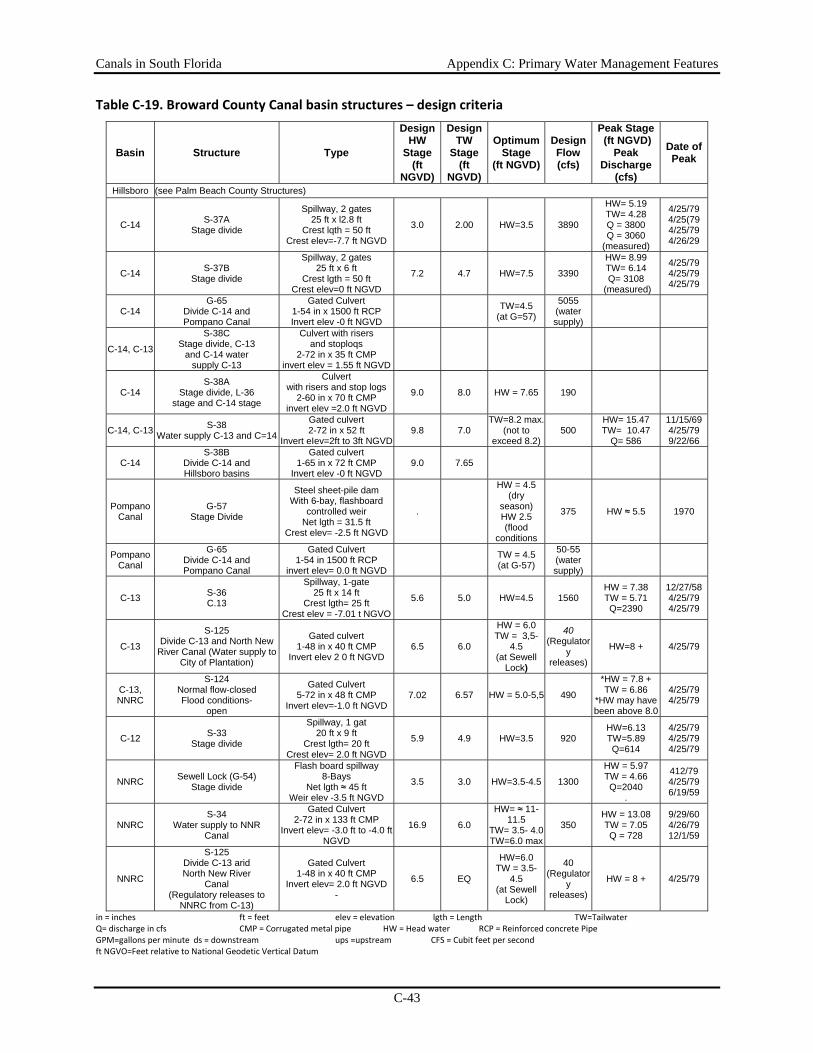
Canals in South Florida Appendix C: Primary Water Management Features
C-43
Table C‐19. Broward County Canal basin structures – design criteria
Basin Structure Type
Design HW
Stage (ft
NGVD)
Design TW
Stage(ft
NGVD)
Optimum Stage
(ft NGVD)
Design Flow (cfs)
Peak Stage (ft NGVD)
Peak Discharge
(cfs)
Date of Peak
Hillsboro (see Palm Beach County Structures)
C-14 S-37A Stage divide
Spillway, 2 gates 25 ft x l2.8 ft
Crest lqth = 50 ft Crest elev=-7.7 ft NGVD
3.0 2.00 HW=3.5 3890
HW= 5.19 TW= 4.28 Q = 3800 Q = 3060
(measured)
4/25/79 4/25(79 4/25/79 4/26/29
C-14 S-37B Stage divide
Spillway, 2 gates 25 ft x 6 ft
Crest lgth = 50 ft Crest elev=0 ft NGVD
7.2 4.7 HW=7.5 3390
HW= 8.99 TW= 6.14 Q= 3108
(measured)
4/25/79 4/25/79 4/25/79
C-14 G-65
Divide C-14 and Pompano Canal
Gated Culvert 1-54 in x 1500 ft RCP Invert elev -0 ft NGVD
TW=4.5 (at G=57)
5055 (water supply)
C-14, C-13
S-38C Stage divide, C-13
and C-14 water supply C-13
Culvert with risers and stoploqs
2-72 in x 35 ft CMP invert elev = 1.55 ft NGVD
C-14 S-38A
Stage divide, L-36 stage and C-14 stage
Culvert with risers and stop logs
2-60 in x 70 ft CMP invert elev =2.0 ft NGVD
9.0 8.0 HW = 7.65 190
C-14, C-13 S-38 Water supply C-13 and C=14
Gated culvert 2-72 in x 52 ft
Invert eIev=2ft to 3ft NGVD 9.8 7.0
TW=8.2 max. (not to
exceed 8.2) 500
HW= 15.47 TW= 10.47
Q= 586
11/15/69 4/25/79 9/22/66
C-14 S-38B
Divide C-14 and Hillsboro basins
Gated culvert 1-65 in x 72 ft CMP
Invert elev -0 ft NGVD 9.0 7.65
Pompano Canal
G-57 Stage Divide
Steel sheet-pile dam With 6-bay, flashboard
controlled weir Net lgth = 31.5 ft
Crest elev= -2.5 ft NGVD
.
HW = 4.5 (dry
season) HW 2.5 (flood
conditions
375 HW ≈ 5.5 1970
Pompano Canal
G-65 Divide C-14 and Pompano Canal
Gated Culvert 1-54 in 1500 ft RCP
invert elev= 0.0 ft NGVD TW = 4.5
(at G-57)
50-55 (water supply)
C-13 S-36 C.13
Spillway, 1-gate 25 ft x 14 ft
Crest lgth= 25 ft Crest elev = -7.01 t NGVO
5.6 5.0 HW=4.5 1560 HW = 7.38 TW = 5.71 Q=2390
12/27/58 4/25/79 4/25/79
C-13
S-125 Divide C-13 and North New
River Canal (Water supply to City of Plantation)
Gated culvert 1-48 in x 40 ft CMP
Invert elev 2 0 ft NGVD 6.5 6.0
HW = 6.0 TW = 3,5-
4.5 (at Sewell
Lock)
40 (Regulator
y releases)
HW=8 + 4/25/79
C-13, NNRC
S-124 Normal flow-closed Flood conditions-
open
Gated Culvert 5-72 in x 48 ft CMP
Invert elev=-1.0 ft NGVD 7.02 6.57 HW = 5.0-5,5 490
*HW = 7.8 + TW = 6.86
*HW may have been above 8.0
4/25/79 4/25/79
C-12 S-33 Stage divide
Spillway, 1 gat 20 ft x 9 ft
Crest lgth= 20 ft Crest elev= 2.0 ft NGVD
5.9 4.9 HW=3.5 920 HW=6.13 TW=5.89 Q=614
4/25/79 4/25/79 4/25/79
NNRC Sewell Lock (G-54) Stage divide
Flash board spillway 8-Bays
Net lgth ≈ 45 ft Weir elev -3.5 ft NGVD
3.5 3.0 HW=3.5-4.5 1300
HW = 5.97 TW = 4.66 Q=2040
.
412/79 4/25/79 6/19/59
NNRC S-34
Water supply to NNR Canal
Gated Culvert 2-72 in x 133 ft CMP
Invert elev= -3.0 ft to -4.0 ft NGVD
16.9 6.0
HW= ≈ 11-11.5
TW= 3.5- 4.0 TW=6.0 max
350 HW = 13.08 TW = 7.05 Q = 728
9/29/60 4/26/79 12/1/59
NNRC
S-125 Divide C-13 arid North New River
Canal (Regulatory releases to
NNRC from C-13)
Gated Culvert 1-48 in x 40 ft CMP
Invert elev= 2.0 ft NGVD -
6.5 EQ
HW=6.0 TW = 3.5-
4.5 (at Sewell
Lock)
40 (Regulator
y releases)
HW = 8 + 4/25/79
in = inches ft = feet elev = elevation lgth = Length TW=Tailwater Q= discharge in cfs CMP = Corrugated metal pipe HW = Head water RCP = Reinforced concrete Pipe GPM=gallons per minute ds = downstream ups =upstream CFS = Cubit feet per second ft NGVO=Feet relative to National Geodetic Vertical Datum
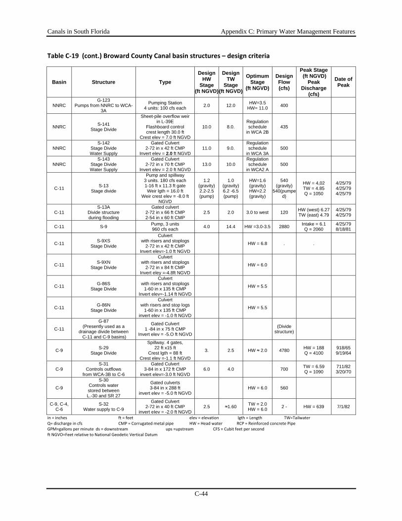
Canals in South Florida Appendix C: Primary Water Management Features
C-44
Table C‐19 (cont.) Broward County Canal basin structures – design criteria
Basin Structure Type Design
HW Stage
(ft NGVD)
Design TW
Stage(ft NGVD)
Optimum Stage
(ft NGVD)
Design Flow (cfs)
Peak Stage (ft NGVD)
Peak Discharge
(cfs)
Date of Peak
NNRC G-123
Pumps from NNRC to WCA- 3A
Pumping Station 4 units: 100 cfs each 2.0 12.0 HW=3.5
HW= 11.0 400
NNRC S-141 Stage Divide
Sheet-pile overflow weir in L-39E
Flashboard control crest length 30.0 ft
Crest elev = 7.0 ft NGVD
10.0 8.0. Regulation schedule
in WCA 2B 435
NNRC S-142
Stage Divide Water Supply
Gated Culvert 2-72 in x 42 ft CMP
Invert elev = 2.0 ft NGVD 11.0 9.0.
Regulation schedule
in WCA 3A 500
NNRC S-143
Stage Divide Water Supply
Gated Culvert 2-72 in x 70 ft CMP
Invert elev = 2.0 ft NGVD 13.0 10.0
Regulation schedule
in WCA2 A 500
C-11 S-13 Stage divide
Pump and spillway 3 units. 180 cfs each 1-16 ft x 11.3 ft gate Weir lgth = 16.0 ft
Weir crest elev = -8.0 ft NGVD
1.2 {gravity) 2.2-2.5 (pump)
1.0 (gravity) 6.2 -6.5 (pump)
HW=1.6 (gravity) HW=2.2 (gravity)
540 (gravity)
540(pumped)
HW = 4,02 TW = 4.85 Q = 1050
4/25/79 4/25/79 4/25/79
C-11 S-13A
Divide structure during flooding
Gated culvert 2-72 in x 66 ft CMP 2-54 in x 60 ft CMP
2.5 2.0 3.0 to west 120 HW (west) 6.27 TW (east) 4.79
4/25/79 4/25/79
C-11 S-9 Pump, 3 units 960 cfs each 4.0 14.4 HW =3.0-3.5 2880 Intake = 6.1
Q = 2060 4/25/79 8/18/81
C-11 S-9XS Stage Divide
Culvert with risers and stoplogs
2-72 in x 42 ft CMP Invert elev=-1.0 ft NGVD
HW = 6.8 . .
C-11 S-9XN Stage Divide
Culvert with risers and stoplogs
2-72 in x 84 ft CMP Invert eley =-4.8ft NGVD
HW = 6.0
C-11 G-86S Stage Divide
Culvert with risers and stoplogs
1-60 in x 135 ft CMP Invert elev=-1.14 ft NGVD
HW = 5.5
C-11 G-86N Stage Divide
Culvert with risers and stop logs
1-60 in x 135 ft CMP invert elev = -1.0 ft NGVD
HW = 5.5
C-11
G-87 (Presently used as a
drainage divide between C-11 and C-9 basins)
Gated Culvert 1 -84 in x 75 ft CMP
Invert elev = -5.O ft NGVD (Divide
structure)
C-9 S-29 Stage Divide
Spillway. 4 gates, 22 ft x15 ft
Crest lgth = 88 ft Crest elev =-1.1 ft NGVD
3. 2.5 HW ≈ 2.0 4780 HW = 188 Q = 4100
918/65 9/19/64
C-9 S-31
Controls outflows from WCA-3B to C-6
Gated Culvert 3-84 in x 172 ft CMP
invert elev=-3.0 ft NGVD 6.0 4.0 700 TW = 6.59
Q = 1090 711/82 3/20/70
C-9
S-30 Controls water stored between L.-30 and SR 27
Gated culverts 3-84 in x 288 ft
invert elev = -5.0 ft NGVD HW = 6.0 560
C-9, C-4, C-6
S-32 Water supply to C-9
Gated Culvert 2-72 in x 40 ft CMP
invert eIev = -2.0 ft NGVD 2.5 ≈1.60 TW = 2.0
HW = 6.0 2 - HW = 639 7/1/82
in = inches ft = feet elev = elevation lgth = Length TW=Tailwater Q= discharge in cfs CMP = Corrugated metal pipe HW = Head water RCP = Reinforced concrete Pipe GPM=gallons per minute ds = downstream ups =upstream CFS = Cubit feet per second ft NGVO=Feet relative to National Geodetic Vertical Datum
Canals in South Florida Appendix C: Primary Water Management Features
C-45
Coastal Basin Canals Coastal basin canals originate at or east of the Everglades and discharge to saline coastal waters of the Intracoastal Waterway. These canals were designed primarily to provide flood protection and drainage for coastal development. Some of the canals are linked directly or indirectly to other canals and the regional canals and provide a means to distribute water from the regional system or from one basin to another during flood or drought periods to regulate surface and groundwater levels and provide recharge to the surficial aquifer. Most of these canals have a downstream water control structure to prevent upstream migration of salt water and consequent intrusion of salt water into groundwater. Some of the coastal canal basins have eastern and western sub-basins. The western basins tend to be more floodprone, and hence have more stringent construction criteria, lower densities of development, and more agricultural use. Within each county, all of the coastal basins are listed and one or more are described in greater detail as examples.
Palm Beach County Four coastal canal basins in eastern Palm Beach County are associated with the C-18, C-17, C-16, and C-15 canals (Figure C-6). The primary functions of these canals are to provide flood protection and drainage for agriculture and urban or residential lands and to regulate groundwater table elevations to prevent saltwater intrusion. Many of the canals are connected directly or indirectly to the larger regional canals and can be used to supply water for irrigation and to recharge the wellfields of local municipalities.
Surface water management throughout most of central Palm Beach County is managed by the Lake Worth Drainage District, which was established under state law (Chapter 298 F.S.) to provide drainage and flood protection and mange groundwater levels within its jurisdiction. Inflows to the SFWMD’s primary canal system in this area of the county (C-51, C-15, C-16, and Hillsboro canals) occur through various LWDD canals. Because some of the north-south flowing LWDD canals do not have divide structures between the C-16 and the C-15 basins, between the C-16 and C-51 Basins, and between the C-15 and the Hillsboro Canal basins, some interbasin transfer of water may occur. This is especially true in the western portions of the basins. Lands in the C-16 and C-15 basins between L-40 and Florida's Turnpike may, under some conditions, drain to the Hillsboro Canal or to C-51.
C-17 Canal
An example of a coastal watersheds in Palm Beach County is the C-17 basin. C-17 is the only C&SF Project canal in a basin of approximately 33.0 square miles, located in northeast Palm Beach County (Figure C-6). Excess water in the basin is discharged to tidewater in the lntracoastal Waterway by way of S-44, which also controls water surface elevations in C-17. In general, the only water supply to the basin is from local rainfall. C-17 is a continuation of a city of West Palm Beach canal and is aligned north-south approximately parallel to and east of 1-95. Inflows to C-17 are by various canals under the management of local municipalities. Two important tributaries are city of West Palm Beach canals that drain the lands in the basin south of 45th Street. These canals join about 1200 feet south of 45th Street to form the canal that continues north of 45th Street as C-17.
Canals in South Florida Appendix C: Primary Water Management Features
C-46
Other Coastal Basins
The C-18 basin (Figure C-6) includes an area of approximately 105.8 square miles. The canal is an extension of the Southwest Fork of the Loxahatchee River. S-46 controls water surface elevations in C-18. The primary functions of the C-18 canal and control structures are flood protection, water supply, and water table maintenance. They also can be used to augment flows in the Northwest Fork of the Loxahatchee River. Water is supplied to the Northwest Fork of the Loxahatchee River from C-18 by way of the G-92 structure and canals of the South Indian River Water Control District (SIRWCD).
C-16 is an extension of the LWDD's Boynton Canal. The C-16 basin has an area of approximately 52.8 square miles (Figure C-6). The Boynton Canal ends and C-16 begins at the Lake Ida Canal. Flow in the canal is to the east with discharge to the Intracoastal Waterway at S-41. Water supply to the basin is from local rainfall and by pumping from WCA-1.
The C-15 basin has an area of approximately 74.6 square miles (Figure C-6). C-15 is an extension of a LWDD lateral (west to east flowing) canal. Flow in the canal is to the east with discharge to the Intracoastal Waterway by way of S-40. Water supply to the basin is from local rainfall and by pumping from WCA-1 and the Hillsboro Canal.
Broward County Six coastal canals are described in Broward County: C-14, C-13, C-12, C-11, C-10, and C-9. The primary function of all the canals is to provide flood protection for the basins in which they occur. Secondary uses of the canals include land drainage for agriculture and urban or residential development, and regulation of groundwater table elevations to prevent saltwater intrusion. Many of the canals are used to supply water for irrigation and to recharge the wellfields of local municipalities.
C-11 (South New River) Canal
The C-11 basin has an area of approximately 104 square miles and is divided into a western (81 square miles) and an eastern basin (23 square miles) (Figure C-6). C-11 is aligned east-west, extending from the L-37 borrow canal on the west to S-13 at U.S. highway 441. The flow in the reach of the canal in the eastern basin moves to the east with discharge to the South Fork of the New River. In the reach of C-11 in the western basin, flow direction depends on the operation of the control structures S-13A and S-9. C-11S begins at G-87 at the south and extends north to make an open channel connection with C-11. Direction of flow in C-11S is to the north. G-87 divides flow in C-11S between the C-11 and the C-9 basins. Excess water in the eastern basin is discharged to the east by way of C-11 and S-13 to the South Fork of the New River. If S-13 is not pumping to capacity, additional discharges of excess water from the western basin can be made to the eastern basin by way of S-13A.
The L-33 and L-37 borrow canals make up a continuous canal aligned north-south along the western boundary of the C-11 basin. The L-33 borrow canal extends south of C-11, makes an open channel connection to the west end of C-9, and is connected to C-6 by way of S-32. Direction of flow in the L-33 borrow canal depends on the operation of S-9XS, S-30, and S-32, and may be either to the north to C-11 or to the south to C-9. The L-37 borrow canal extends north of C-11 toward the North New River Canal. Flow in the L-37 borrow canal is to the south to C-11.
Canals in South Florida Appendix C: Primary Water Management Features
C-47
Other Coastal Basins
The C-14 basin has an area of 59 square miles and is divided into an eastern (34 square miles) and a western basin (25 square miles, Figure C-6). The western basin was designed for 1 in 10-year flood protection and the eastern basin was designed for 1 in 30-year flood protection. Besides flood protection, the C-14 canal and the control structures supply water, maintain the water table, convey excess water from WCA-2A to tidewater, and intercept and control seepage from WCA-2A. The C-14 canal extends from east to west in the alignment of the old Pompano Canal with discharge to the lntracoastal Waterway at structure S-37A. The Pompano Canal basin has an area of approximately 7.2 square miles. G-57 controls water surface elevations upstream in the Pompano Canal and it regulates discharges to tidewater. At its west end, the canal connects to C-14 by way of G-65. Water supply to the basin is from C-14 through G-65 and from local rainfall
The C-13 basin has an area of approximately 39 square miles and is divided into an eastern basin (9 square miles) and a western basin (30 square miles, Figure C-6) by S-36. The C&SF Project canals and control structures in the C-13 basin provide flood protection and drainage, supply water, intercept and control seepage from WCA-2B, and maintain a groundwater table elevation west of S-36 adequate to prevent saltwater intrusion.
The C-12 basin has an area of approximately 19 square miles. The canal and control structure provide flood protection and drainage, and maintain adequate groundwater levels west of S-33. C-12 is aligned east-west from University Drive on the west to S-33 on the east. East of S-33, C-12 follows the old channel of the North Fork of the New River.
The C-10 basin has an area of approximately 15 square miles. The C&SF Project canals in the C-10 basin provide flood protection and drainage. There is no regulation of water surface elevations and discharge from the basin is not controlled.
The C-9 basin has an area of approximately 98 square miles and is located in northeastern Miami-Dade County and southeastern Broward County The basin includes two sub-basins, C-9 east (45 square miles) and C-9 west (53 square miles). The C-9 Canal is aligned east-west extending from L-33 on the west to Dumfoundling Bay on the east. S-29 controls water surface elevations in C-9, and regulates discharges to tidewater. At its western end, C-9 makes an open channel connection with the L-33 borrow canal. Seepage from WCA-3B is a major contributor to flows in C-9. S-30 may be opened to supply water to the C-9 basin as necessary to maintain an optimum stage at S-29.
Miami-Dade County Seventeen basins are described within eastern Miami-Dade County. They include the C-1, C-2, C-3, C-4, C-5, C-6, C-7, C-8, C-9, C-100, C-102, C-103, C-111, North Canal, Florida City Canal, Model Land, and Homestead Air Force Base basins. The primary function of the 20 C&SF Project canals and six levee borrow canals in Miami-Dade County is to provide flood protection. Secondary uses include land drainage for agriculture and urban or residential development, and regulation of groundwater table elevations to prevent saltwater intrusion. Many of the canals are used to supply water for irrigation and to recharge local wellfields. Two canals, C-6 and C-4, discharge excess water from the Water Conservation Areas to tidewater. Features of the 56 C&SF Project control structures in Miami-Dade County are provided in Table C-20. Two examples of coastal watersheds in Miami-Dade County are discussed below.
Canals in South Florida Appendix C: Primary Water Management Features
C-48
C-4 (Tamiaml) Canal
The C-4 basin has an area of approximately 60.9 square miles (Figure C-6). The area in the C-4 basin between Krome Avenue and the Miami-Dade-Broward levee drains to C-4 by an open channel between S-336 and G-119. When drainage from the rest of the basin and from the C-2 and C-3 basins is adequate to supply the water needs of the three basins, S-336 and G-119 are closed, and rainfall on the area is impounded and stored. The stored water can be released to C-4 by way of G-119 as needed to meet water demands in the C-2, C-3, and C-4 basins. S-25B controls water surface elevations in C-4 and regulates discharges to C-6. S-25A is a divide structure between the C-4 and C-5 basins.
Flow in the C-4 canal is to the east with discharge to tidewater in C-6. C-4 is connected to three other C&SF Project canals: C-2, C-3, and C-5. These three canals are bifurcations of C-4. C-2, the Snapper Creek Canal, makes an open channel connection with C-4. Normal flow is from C-4 to C-2. C-3, the Coral Gables Canal, makes an open channel connection to C-4. Flow is normally from C-4 to C-3, however, during the dry season a low stage at S-25B can cause flow from C-3 to C-4. C-5 branches from C-4 at Blue Lagoon east of Coral Gables and connects downstream to C-6. Normal flow is from C-5 to C-6. During periods of low natural flow, water is supplied as needed to the C-4 basin from WCA-3A and WCA-3B by way of the South Dade Conveyance System (SDCS). Water can be frequently diverted from C-4 to the C-2, C-3, and C-5 basins. The portion of the C-4 basin west of S.W. 87th Avenue is in Area B. The drainage from this area is limited, and the area is subject to severe limitations on development. The L-30 borrow canal is aligned north-south along the west boundary of the basin and is connected to C-4 at its west end by S-335. The borrow canal is part of the SDCS that supplies water to south Miami-Dade County.
C-100, C-100A, C-100B, C-100C Canals
The C-100 basin has an area of approximately 40.6 square miles and is located in eastern Miami-Dade County (Figure C-6). This basin is also known as the Cutler Drainage Basin. There are four C&SF Project canals in the C-100 basin: C-100, C-100A. C-100B, and C-100C. These canals have three functions: (1) provide drainage and flood protection for the C-100 basin, (2) supply water to the basin for irrigation, and (3) maintain a groundwater table elevation near the lower reach of C-100 adequate to prevent saltwater intrusion to local groundwater. C-100 begins just north of the intersection of Killian Road and Lingren Road. Flow in the canal is to the southeast with discharge via S-123 to Biscayne Bay. S-118 controls the stage in the upper reach of C-100, and regulates discharges to the lower reach of C-100. C-100A, C-100B, and C-100C are tributaries to C-100. Flow in C-100A begins at S-121, which conveys flows from local drainage systems, and continues south to the canal's confluence with C-100. C-100B enters the C-100 basin at S-122 and connects C-100 to C-1. Normal flows in C-100B are to the northeast to the canal's confluence with C-100. C-100C connects C-100 to C-2. C-100C enters the C-100 basin at S-121. Normal flows in C-100C are to the southeast to the canal's confluence with C-100A. S-119, located in C-100C, controls the stage in the upper reach of C-100C and regulates discharges to C-100A and C-100. Water is supplied to the basin during periods of low natural flow from C-1 by way of S-122 and C-100B and from C-2 by way of S-121 and C-100C.
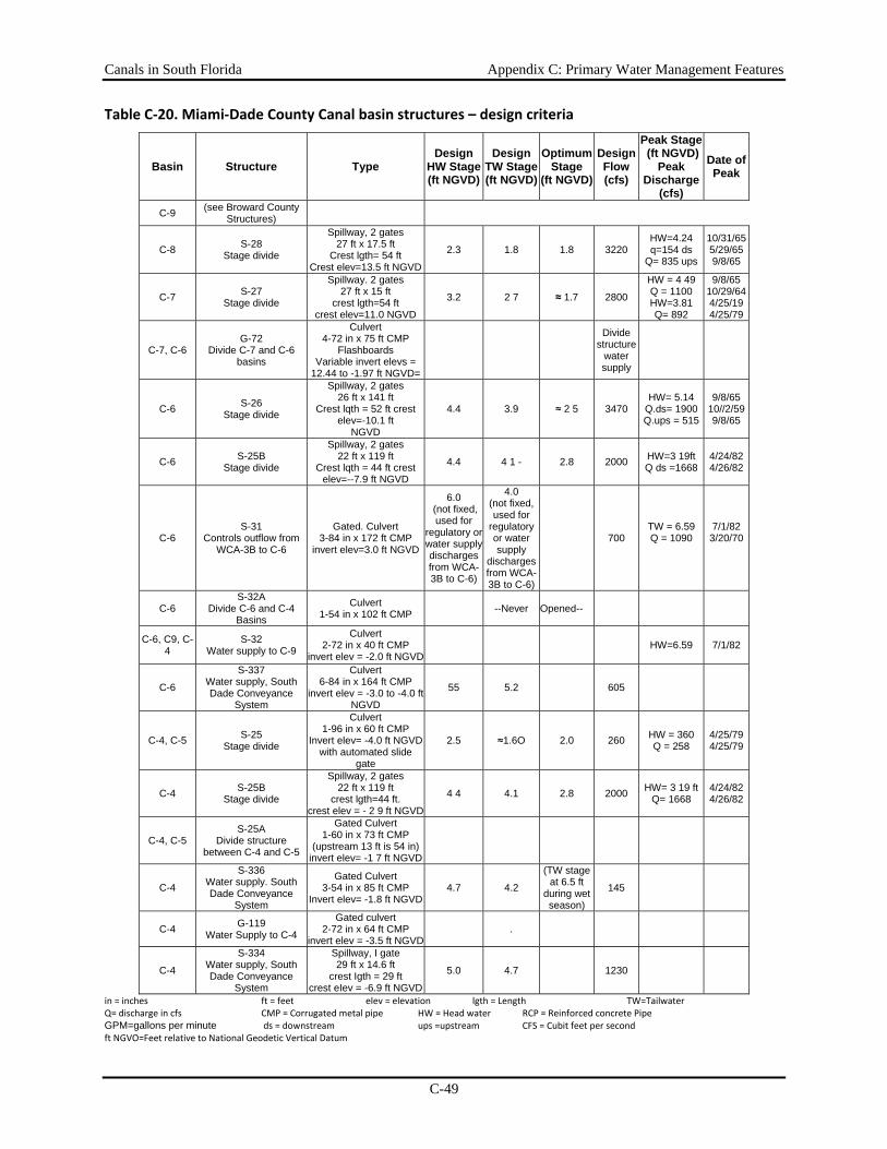
Canals in South Florida Appendix C: Primary Water Management Features
C-49
Table C‐20. Miami‐Dade County Canal basin structures – design criteria
Basin Structure Type Design
HW Stage (ft NGVD)
Design TW Stage(ft NGVD)
Optimum Stage
(ft NGVD)
Design Flow (cfs)
Peak Stage (ft NGVD)
Peak Discharge
(cfs)
Date of Peak
C-9 (see Broward County Structures)
C-8 S-28 Stage divide
Spillway, 2 gates 27 ft x 17.5 ft
Crest lgth= 54 ft Crest elev=13.5 ft NGVD
2.3 1.8 1.8 3220 HW=4.24 q=154 ds
Q= 835 ups
10/31/655/29/659/8/65
C-7 S-27 Stage divide
Spillway. 2 gates 27 ft x 15 ft
crest lgth=54 ft crest elev=11.0 NGVD
3.2 2 7 ≈ 1.7 2800
HW = 4 49 Q = 1100 HW=3.81 Q= 892
9/8/65 10/29/64 4/25/19 4/25/79
C-7, C-6 G-72
Divide C-7 and C-6 basins
Culvert 4-72 in x 75 ft CMP
Flashboards Variable invert elevs =
12.44 to -1.97 ft NGVD=
Divide
structure water supply
C-6 S-26 Stage divide
Spillway, 2 gates 26 ft x 141 ft
Crest lqth = 52 ft crest elev=-10.1 ft
NGVD
4.4 3.9 ≈ 2 5 3470 HW= 5.14
Q.ds= 1900 Q.ups = 515
9/8/65 10//2/59 9/8/65
C-6 S-25B Stage divide
Spillway, 2 gates 22 ft x 119 ft
Crest lqth = 44 ft crest elev=--7.9 ft NGVD
4.4 4 1 - 2.8 2000 HW=3 19ft Q ds =1668
4/24/82 4/26/82
C-6 S-31
Controls outflow from WCA-3B to C-6
Gated. Culvert 3-84 in x 172 ft CMP
invert elev=3.0 ft NGVD
6.0 (not fixed, used for
regulatory or water supply discharges from WCA-3B to C-6)
4.0 (not fixed, used for
regulatory or water supply
discharges from WCA-3B to C-6)
700 TW = 6.59 Q = 1090
7/1/823/20/70
C-6 S-32A
Divide C-6 and C-4 Basins
Culvert 1-54 in x 102 ft CMP --Never Opened--
C-6, C9, C-4
S-32 Water supply to C-9
Culvert 2-72 in x 40 ft CMP
invert elev = -2.0 ft NGVD
HW=6.59 7/1/82
C-6
S-337 Water supply, South Dade Conveyance
System
Culvert 6-84 in x 164 ft CMP
invert elev = -3.0 to -4.0 ft NGVD
55 5.2 605
C-4, C-5 S-25 Stage divide
Culvert 1-96 in x 60 ft CMP
Invert elev= -4.0 ft NGVD with automated slide
gate
2.5 ≈1.6O 2.0 260 HW = 360 Q = 258
4/25/79 4/25/79
C-4 S-25B Stage divide
Spillway, 2 gates 22 ft x 119 ft
crest lgth=44 ft. crest elev = - 2 9 ft NGVD
4 4 4.1 2.8 2000 HW= 3 19 ft Q= 1668
4/24/82 4/26/82
C-4, C-5 S-25A
Divide structure between C-4 and C-5
Gated Culvert 1-60 in x 73 ft CMP
(upstream 13 ft is 54 in) invert elev= -1 7 ft NGVD
C-4
S-336 Water supply. South Dade Conveyance
System
Gated Culvert 3-54 in x 85 ft CMP
Invert elev= -1.8 ft NGVD4.7 4.2
(TW stage at 6.5 ft
during wet season)
145
C-4 G-119 Water Supply to C-4
Gated culvert 2-72 in x 64 ft CMP
invert elev = -3.5 ft NGVD .
C-4
S-334 Water supply, South Dade Conveyance
System
Spillway, I gate 29 ft x 14.6 ft
crest Igth = 29 ft crest eIev = -6.9 ft NGVD
5.0 4.7 1230
in = inches ft = feet elev = elevation lgth = Length TW=Tailwater Q= discharge in cfs CMP = Corrugated metal pipe HW = Head water RCP = Reinforced concrete Pipe GPM=gallons per minute ds = downstream ups =upstream CFS = Cubit feet per second ft NGVO=Feet relative to National Geodetic Vertical Datum
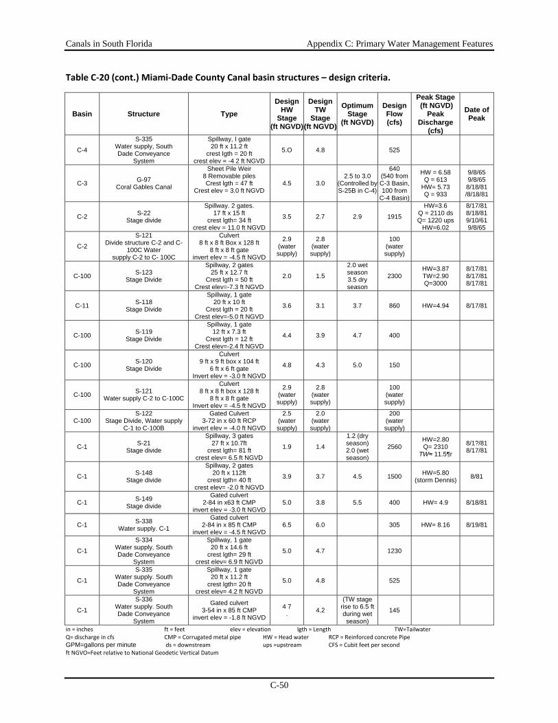
Canals in South Florida Appendix C: Primary Water Management Features
C-50
Table C‐20 (cont.) Miami‐Dade County Canal basin structures – design criteria.
Basin Structure Type Design
HW Stage
(ft NGVD)
Design TW
Stage(ft NGVD)
Optimum Stage
(ft NGVD)
Design Flow (cfs)
Peak Stage (ft NGVD)
Peak Discharge
(cfs)
Date of Peak
C-4
S-335 Water supply, South Dade Conveyance
System
Spillway, I gate 20 ft x 11.2 ft
crest Igth = 20 ft crest elev = -4 2 ft NGVD
5.O 4.8 525
C-3 G-97 Coral Gables Canal
Sheet Pile Weir 8 Removable piles Crest lgth = 47 ft
Crest elev = 3.0 ft NGVD
4.5 3.0 2.5 to 3.0
(Controlled by S-25B in C-4)
640 (540 from C-3 Basin, 100 from
C-4 Basin)
HW = 6.58 Q = 613
HW= 5.73 Q = 933
9/8/65 9/8/65 8/18/81 /8/18/81
C-2 S-22 Stage divide
Spillway. 2 gates. 17 ft x 15 ft
crest lgth= 34 ft crest elev = 11.0 ft NGVD
3.5 2.7 2.9 1915
HW=3.6 Q = 2110 dsQ= 1220 ups
HW=6.02
8/17/81 8/18/81 9/10/61 9/8/65
C-2
S-121 Divide structure C-2 and C-
100C Water supply C-2 to C- 100C
Culvert 8 ft x 8 ft Box x 128 ft
8 ft x 8 ft gate invert elev = -4.5 ft NGVD
2.9 (water supply)
2.8 (water supply)
100
(water supply)
C-100 S-123 Stage Divide
Spillway, 2 gates 25 ft x 12.7 ft
Crest lgth = 50 ft Crest elev=-7.3 ft NGVD
2.0 1.5
2.0 wet season 3.5 dry season
2300 HW=3.87 TW=2.90 Q=3000
8/17/818/17/818/17/81
C-11 S-118 Stage Divide
Spillway, 1 gate 20 ft x 10 ft
Crest lgth = 20 ft Crest elev=-5.0 ft NGVD
3.6 3.1 3.7 860 HW=4.94 8/17/81
C-100 S-119 Stage Divide
Spillway, 1 gate 12 ft x 7.3 ft
Crest lgth = 12 ft Crest elev=-2.4 ft NGVD
4.4 3.9 4.7 400
C-100 S-120 Stage Divide
Culvert 9 ft x 9 ft box x 104 ft
6 ft x 6 ft gate Invert elev = -3.0 ft NGVD
4.8 4.3 5.0 150
C-100 S-121 Water supply C-2 to C-100C
Culvert 8 ft x 8 ft box x 128 ft
8 ft x 8 ft gate Invert elev = -4.5 ft NGVD
2.9 (water supply)
2.8 (water supply)
100
(water supply)
C-100 S-122
Stage Divide, Water supply C-1 to C-100B
Gated Culvert 3-72 in x 60 ft RCP
invert elev = -4.0 ft NGVD
2.5 (water supply)
2.0 (water supply)
200
(water supply)
C-1 S-21 Stage divide
Spillway, 3 gates 27 ft x 10.7ft
crest lgth= 81 ft crest elev= 6.5 ft NGVD
1.9 1.4
1.2 (dry season) 2.0 (wet season)
2560 HW=2.80 Q= 2310
TW≈ 11.5¶r
8/1?/81 8/17/81
C-1 S-148 Stage divide
Spillway, 2 gates 20 ft x 112ft
crest lgth= 40 ft crest elev= -2.0 ft NGVD
3.9 3.7 4.5 1500 HW=5.80 (storm Dennis) 8/81
C-1 S-149 Stage divide
Gated culvert 2-84 in x63 ft CMP
invert elev = -3.0 ft NGVD 5.0 3.8 5.5 400 HW= 4.9 8/18/81
C-1 S-338 Water supply. C-1
Gated culvert 2-84 in x 85 ft CMP
invert elev = -4.5 ft NGVD 6.5 6.0 305 HW= 8.16 8/19/81
C-1
S-334 Water supply, South Dade Conveyance
System
Spillway, 1 gate 20 ft x 14.6 ft
crest lgth= 29 ft crest elev= 6.9 ft NGVD
5.0 4.7 1230
C-1
S-335 Water supply. South Dade Conveyance
System
Spillway, 1 gate 20 ft x 11.2 ft
crest lgth= 20 ft crest elev= 4.2 ft NGVD
5.0 4.8 525
C-1
S-336 Water supply. South Dade Conveyance
System
Gated culvert 3-54 in x 85 ft CMP
invert elev = -1.8 ft NGVD
4 7 . 4.2
(TW stage rise to 6.5 ft during wet season)
145
in = inches ft = feet elev = elevation lgth = Length TW=Tailwater Q= discharge in cfs CMP = Corrugated metal pipe HW = Head water RCP = Reinforced concrete Pipe GPM=gallons per minute ds = downstream ups =upstream CFS = Cubit feet per second ft NGVO=Feet relative to National Geodetic Vertical Datum
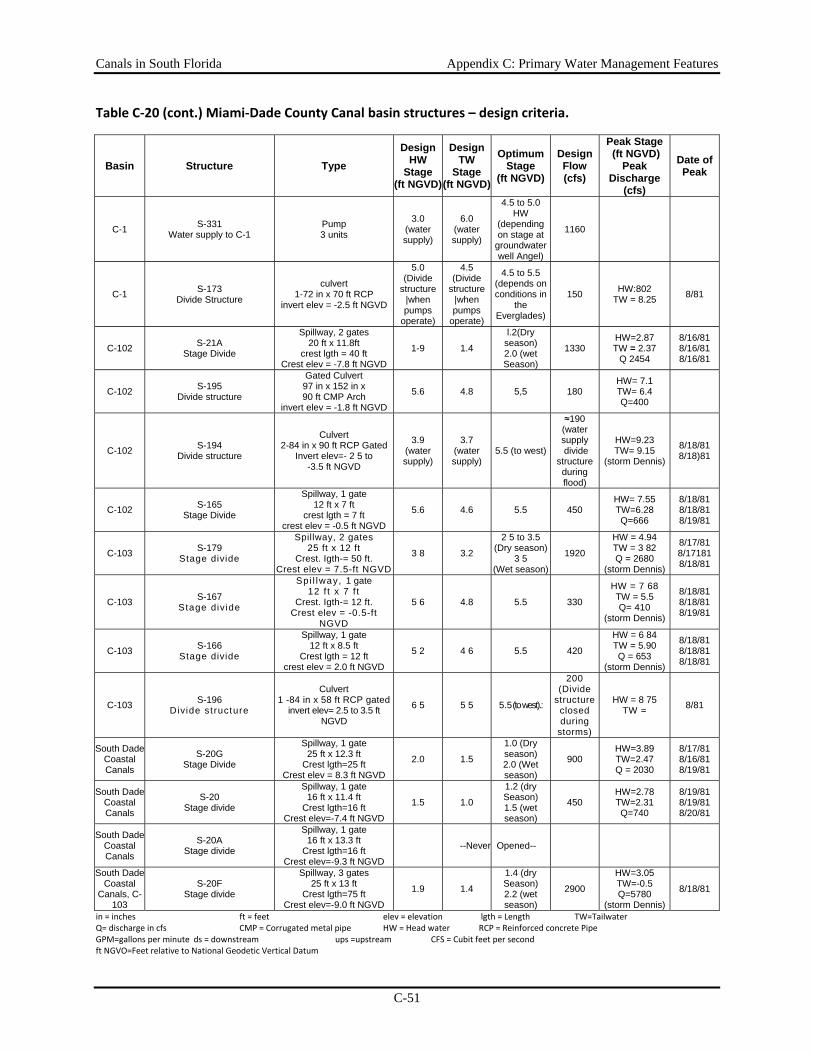
Canals in South Florida Appendix C: Primary Water Management Features
C-51
Table C‐20 (cont.) Miami‐Dade County Canal basin structures – design criteria.
Basin Structure Type Design
HW Stage
(ft NGVD)
Design TW
Stage(ft NGVD)
Optimum Stage
(ft NGVD)
Design Flow (cfs)
Peak Stage (ft NGVD)
Peak Discharge
(cfs)
Date of Peak
C-1 S-331 Water supply to C-1
Pump 3 units
3.0 (water supply)
6.0 (water supply)
4.5 to 5.0HW
(depending on stage at
groundwater well Angel)
1160
C-1 S-173 Divide Structure
culvert 1-72 in x 70 ft RCP
invert elev = -2.5 ft NGVD
5.0 (Divide
structure |when pumps
operate)
4.5 (Divide
structure |when pumps
operate)
4.5 to 5.5(depends on conditions in
the Everglades)
150 HW:802 TW = 8.25 8/81
C-102 S-21A Stage Divide
Spillway, 2 gates 20 ft x 11.8ft
crest lgth = 40 ft Crest elev = -7.8 ft NGVD
1-9 1.4
l.2(Dry season) 2.0 (wet Season)
1330 HW=2.87 TW = 2.37
Q 2454
8/16/81 8/16/81 8/16/81
C-102 S-195 Divide structure
Gated Culvert 97 in x 152 in x 90 ft CMP Arch
invert elev = -1.8 ft NGVD
5.6 4.8 5,5 180 HW= 7.1 TW= 6.4 Q=400
C-102 S-194 Divide structure
Culvert 2-84 in x 90 ft RCP Gated
Invert elev=- 2 5 to -3.5 ft NGVD
3.9 (water supply)
3.7 (water supply)
5.5 (to west)
≈190 (water supply divide
structure during flood)
HW=9.23 TW= 9.15
(storm Dennis)
8/18/81 8/18)81
C-102 S-165 Stage Divide
Spillway, 1 gate 12 ft x 7 ft
crest lgth = 7 ft crest elev = -0.5 ft NGVD
5.6 4.6 5.5 450 HW= 7.55 TW=6.28 Q=666
8/18/81 8/18/81 8/19/81
C-103 S-179 Stage divide
Spillway, 2 gates 25 ft x 12 ft
Crest. Igth-= 50 ft. Crest elev = 7.5-ft NGVD
3 8 3.2
2 5 to 3.5 (Dry season)
3 5 (Wet season)
1920
HW = 4.94 TW = 3 82 Q = 2680
(storm Dennis)
8/17/81 8/17181 8/18/81
C-103 S-167 Stage divide
Spi l lway, 1 gate 12 f t x 7 f t
Crest. Igth-= 12 ft. Crest elev = -0.5-ft
NGVD
5 6 4.8 5.5 330
HW = 7 68 TW = 5.5 Q= 410
(storm Dennis)
8/18/81 8/18/81 8/19/81
C-103 S-166 Stage divide
Spillway, 1 gate 12 ft x 8.5 ft
Crest lgth = 12 ft crest elev = 2.0 ft NGVD
5 2 4 6 5.5 420
HW = 6 84 TW = 5.90 Q = 653
(storm Dennis)
8/18/81 8/18/81 8/18/81
C-103 S-196 Divide st ructure
Culvert 1 -84 in x 58 ft RCP gated
invert elev= 2.5 to 3.5 ft NGVD
6 5 5 5 5.5 (to west).:
200 (Divide
structure closed during
storms)
HW = 8 75 TW = 8/81
South Dade Coastal Canals
S-20G Stage Divide
Spillway, 1 gate 25 ft x 12.3 ft
Crest lgth=25 ft Crest elev = 8.3 ft NGVD
2.0 1.5
1.0 (Dry season) 2.0 (Wet season)
900 HW=3.89 TW=2.47 Q = 2030
8/17/81 8/16/81 8/19/81
South Dade Coastal Canals
S-20 Stage divide
Spillway, 1 gate 16 ft x 11.4 ft
Crest lgth=16 ft Crest elev=-7.4 ft NGVD
1.5 1.0
1.2 (dry Season) 1.5 (wet season)
450 HW=2.78 TW=2.31 Q=740
8/19/81 8/19/818/20/81
South Dade Coastal Canals
S-20A Stage divide
Spillway, 1 gate 16 ft x 13.3 ft
Crest lgth=16 ft Crest elev=-9.3 ft NGVD
--Never Opened--
South Dade Coastal
Canals, C-103
S-20F Stage divide
Spillway, 3 gates 25 ft x 13 ft
Crest lgth=75 ft Crest elev=-9.0 ft NGVD
1.9 1.4
1.4 (dry Season) 2.2 (wet season)
2900
HW=3.05 TW=-0.5 Q=5780
(storm Dennis)
8/18/81
in = inches ft = feet elev = elevation lgth = Length TW=Tailwater Q= discharge in cfs CMP = Corrugated metal pipe HW = Head water RCP = Reinforced concrete Pipe GPM=gallons per minute ds = downstream ups =upstream CFS = Cubit feet per second ft NGVO=Feet relative to National Geodetic Vertical Datum

Canals in South Florida Appendix C: Primary Water Management Features
C-52
Table C‐20 (cont.) Miami‐Dade County Canal basin structures – design criteria.
Basin Structure Type Design
HW Stage
(ft NGVD)
Design TW
Stage(ft NGVD)
Optimum Stage
(ft NGVD)
Design Flow (cfs)
Peak Stage (ft NGVD)
Peak Discharge
(cfs)
Date of Peak
C-111 S-177 Stage divide
Spillway, 1 gate 22 ft x 12 ft
crest lgth = 22 ft Crest elev = -2.1 ft NGVD
4 7 4 2
2.8-3.3 (October)
3.0-3.? (.after planting to harvest)
3.6-4.2 (rest of year):
1400
HW = 4 94 TW = 4.30
Q 1695 (Storm Dennis)
8/18/81 8/18/818/19/81
C-111 S-176 Stage divide
Spillway, 1 gate 20 ft x 8 ft
crest lgth = 20 ft Crest elev = -1.0 ft NGVD
63 5.9 5.5 630
HW=? 53 TW = 7.15
Q=888 (Storm Dennis)
8/18/81 8/18/818/19/81
C-111 S-174 Stage divide
Spillway, 1 gate 16 ft x 8 ft
crest lgth = 16 ft Crest elev = -1.5 ft NGVD
6.0 5.5
TW = 3.5 (Oct to Feb or
Mar HW = 4 5
500 HW= 7.56 TW = 7.18 Q = 550
8/18181 8/18/81 8/18/81
C-111 S-175 Stage divide
Culvert 3-84 in x 56 ft RCP gated
invert elev = -5.0 ft NGVD
5.0 4.5
HW=3.5 (Oct to end
of harvest) HW= 4 5 (rest
of year)
500
HW= 5.85 1W = 5 16
Q 534 (storm Dennis)
8/18181 8/20/81 8/19/81
C-111 S-332
Water Supply to TayIor Slough or ENP
Pump,6 units 2.0 <5.8 165
C-111 S-196 Divide Structure
Culvert 1-84 in x 58 ft RCP gated invert elev = -2.5 to 3.5 ft
NGVD
6.5 5.5 5.5 (to west)
200 cfs at 1 ft (divide structure closed during storms)
HW = =8.75 TW = (under
water in storm Dennis)
8/81
C-111 S-194 Divide Structure
Culvert 2-84 in x 90 ft RCP gated invert elev = -2.5 to 3.5 ft
NGVD
3.9 (water supply)
3.7 (water supply)
5.5 (to west)
-190 - - (water supply divide
structure during
droughts)
HW = 9.23 - TW = 9.15
:5i ..i. i .
8/18/81 8/18/81
C-111 S-173 Divide structure
Culvert 1-72 in x 70 ft RCP
invert elev = -2.5 ft NGVD
5.0 Divide
structure when pump
operates
4.5 Divide
structure when pump
operates
4.5 to 5.5 (depending
on conditions in
the Everglades)
150 HW = 8.02 TW = 8 25
(Storm Dennis)’8/81
C-111 S-178 Stage divide
Box culvert 12 ft x 10 ft controlled by 2-8ftx 8 ft gates. Top of
gate closed at 5.0 ft
4.6 3.9 4.5 300
C-111 S-197 Flood Discharges
Gated culvert 3-84 in x 66 ft CMP
Invert elev=8.0 ft NGVD 1.4 0.6
Normally closed
(Open when S-18C
TW= 1.9 ; open
when HW =1.6)
550 HW = 2.74 Q = 3430
C-111 S-18C Stage divide
Spillway 2 gates, 22 ft x 11 ft
Crest lgth = 44 ft Crest elev = 7.0 ft NGVD
3.3 2.8 HW = 2.3 ft NGVD 2100
HW 3.20 TW=2 90 Q = 2170
C-111 S-331
Water supply to C-111
Pump, 3 units 3 0
(water supply)
6.0 (water supply)
HWI = 4.5 – 5.0
NGVD HW4.S - 5.0 (depending on stage at
ground water well Angel)
1160
in = inches ft = feet elev = elevation lgth = Length TW=Tailwater Q= discharge in cfs CMP = Corrugated metal pipe HW = Head water RCP = Reinforced concrete Pipe GPM=gallons per minute ds = downstream ups =upstream CFS = Cubit feet per second
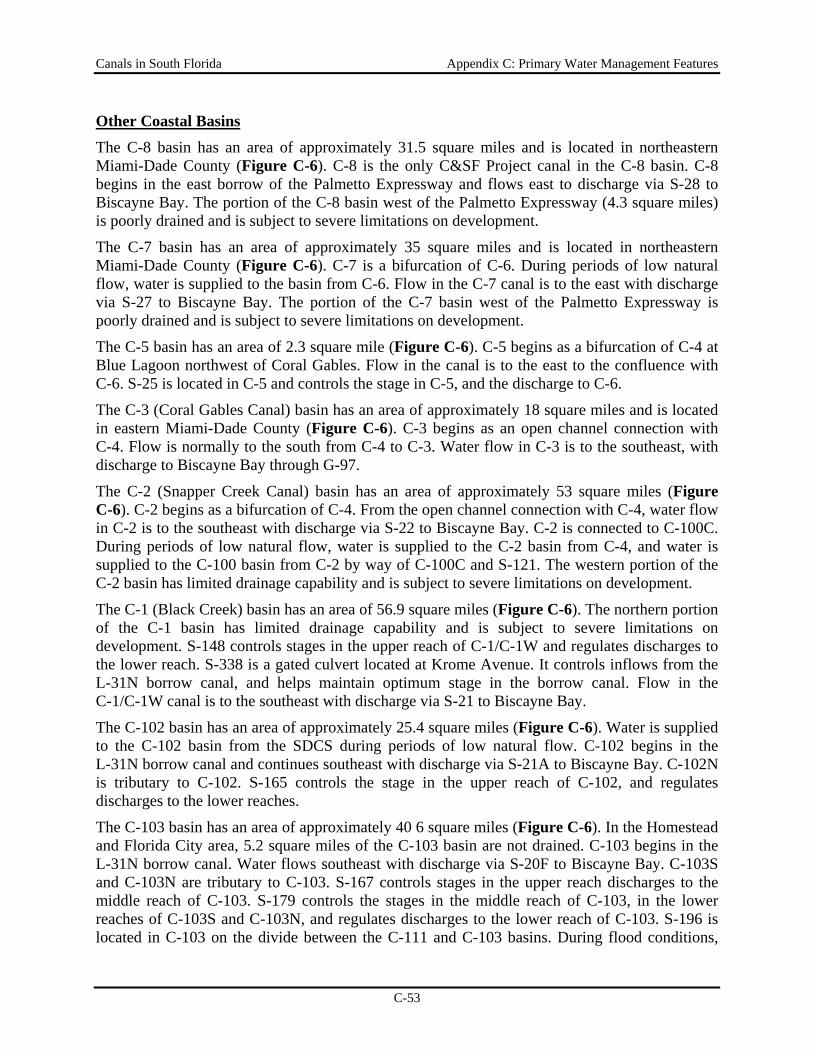
Canals in South Florida Appendix C: Primary Water Management Features
C-53
Other Coastal Basins The C-8 basin has an area of approximately 31.5 square miles and is located in northeastern Miami-Dade County (Figure C-6). C-8 is the only C&SF Project canal in the C-8 basin. C-8 begins in the east borrow of the Palmetto Expressway and flows east to discharge via S-28 to Biscayne Bay. The portion of the C-8 basin west of the Palmetto Expressway (4.3 square miles) is poorly drained and is subject to severe limitations on development.
The C-7 basin has an area of approximately 35 square miles and is located in northeastern Miami-Dade County (Figure C-6). C-7 is a bifurcation of C-6. During periods of low natural flow, water is supplied to the basin from C-6. Flow in the C-7 canal is to the east with discharge via S-27 to Biscayne Bay. The portion of the C-7 basin west of the Palmetto Expressway is poorly drained and is subject to severe limitations on development.
The C-5 basin has an area of 2.3 square mile (Figure C-6). C-5 begins as a bifurcation of C-4 at Blue Lagoon northwest of Coral Gables. Flow in the canal is to the east to the confluence with C-6. S-25 is located in C-5 and controls the stage in C-5, and the discharge to C-6.
The C-3 (Coral Gables Canal) basin has an area of approximately 18 square miles and is located in eastern Miami-Dade County (Figure C-6). C-3 begins as an open channel connection with C-4. Flow is normally to the south from C-4 to C-3. Water flow in C-3 is to the southeast, with discharge to Biscayne Bay through G-97.
The C-2 (Snapper Creek Canal) basin has an area of approximately 53 square miles (Figure C-6). C-2 begins as a bifurcation of C-4. From the open channel connection with C-4, water flow in C-2 is to the southeast with discharge via S-22 to Biscayne Bay. C-2 is connected to C-100C. During periods of low natural flow, water is supplied to the C-2 basin from C-4, and water is supplied to the C-100 basin from C-2 by way of C-100C and S-121. The western portion of the C-2 basin has limited drainage capability and is subject to severe limitations on development.
The C-1 (Black Creek) basin has an area of 56.9 square miles (Figure C-6). The northern portion of the C-1 basin has limited drainage capability and is subject to severe limitations on development. S-148 controls stages in the upper reach of C-1/C-1W and regulates discharges to the lower reach. S-338 is a gated culvert located at Krome Avenue. It controls inflows from the L-31N borrow canal, and helps maintain optimum stage in the borrow canal. Flow in the C-1/C-1W canal is to the southeast with discharge via S-21 to Biscayne Bay.
The C-102 basin has an area of approximately 25.4 square miles (Figure C-6). Water is supplied to the C-102 basin from the SDCS during periods of low natural flow. C-102 begins in the L-31N borrow canal and continues southeast with discharge via S-21A to Biscayne Bay. C-102N is tributary to C-102. S-165 controls the stage in the upper reach of C-102, and regulates discharges to the lower reaches.
The C-103 basin has an area of approximately 40 6 square miles (Figure C-6). In the Homestead and Florida City area, 5.2 square miles of the C-103 basin are not drained. C-103 begins in the L-31N borrow canal. Water flows southeast with discharge via S-20F to Biscayne Bay. C-103S and C-103N are tributary to C-103. S-167 controls stages in the upper reach discharges to the middle reach of C-103. S-179 controls the stages in the middle reach of C-103, in the lower reaches of C-103S and C-103N, and regulates discharges to the lower reach of C-103. S-196 is located in C-103 on the divide between the C-111 and C-103 basins. During flood conditions,
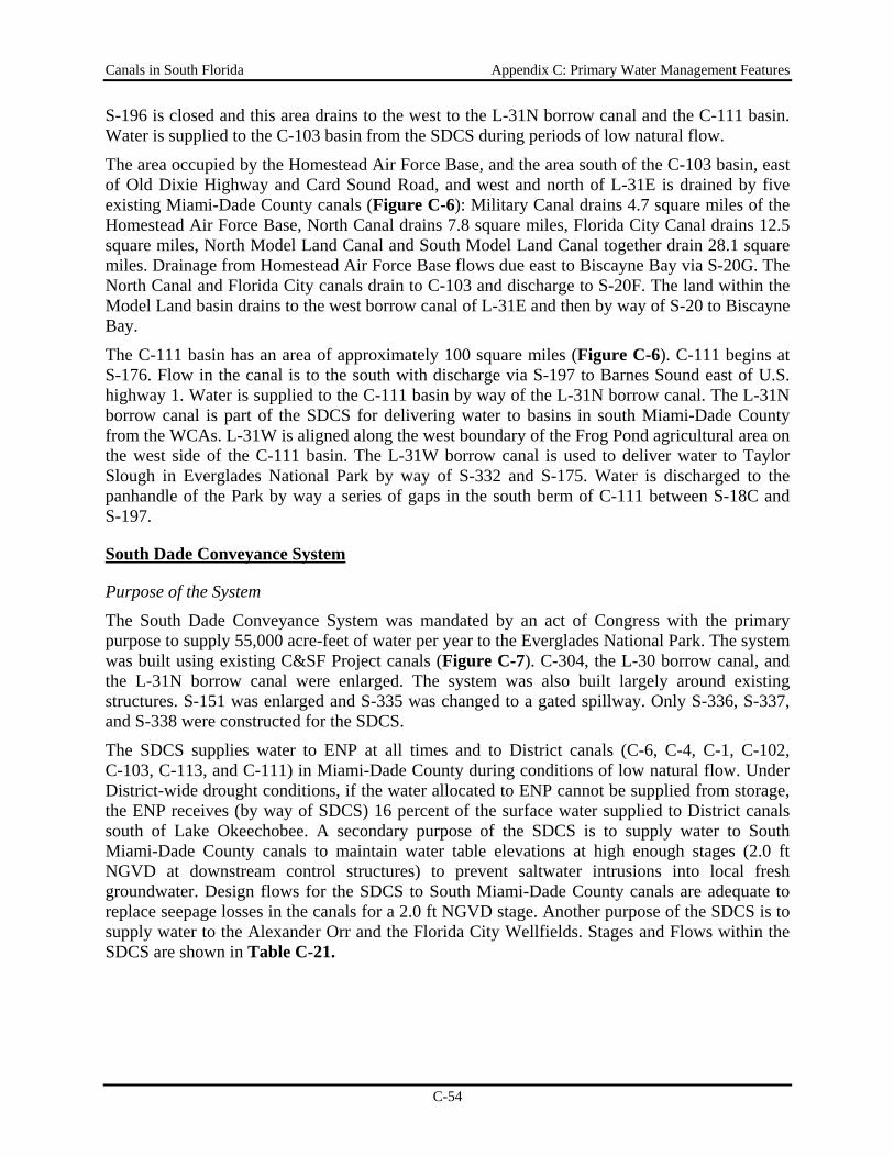
Canals in South Florida Appendix C: Primary Water Management Features
C-54
S-196 is closed and this area drains to the west to the L-31N borrow canal and the C-111 basin. Water is supplied to the C-103 basin from the SDCS during periods of low natural flow.
The area occupied by the Homestead Air Force Base, and the area south of the C-103 basin, east of Old Dixie Highway and Card Sound Road, and west and north of L-31E is drained by five existing Miami-Dade County canals (Figure C-6): Military Canal drains 4.7 square miles of the Homestead Air Force Base, North Canal drains 7.8 square miles, Florida City Canal drains 12.5 square miles, North Model Land Canal and South Model Land Canal together drain 28.1 square miles. Drainage from Homestead Air Force Base flows due east to Biscayne Bay via S-20G. The North Canal and Florida City canals drain to C-103 and discharge to S-20F. The land within the Model Land basin drains to the west borrow canal of L-31E and then by way of S-20 to Biscayne Bay.
The C-111 basin has an area of approximately 100 square miles (Figure C-6). C-111 begins at S-176. Flow in the canal is to the south with discharge via S-197 to Barnes Sound east of U.S. highway 1. Water is supplied to the C-111 basin by way of the L-31N borrow canal. The L-31N borrow canal is part of the SDCS for delivering water to basins in south Miami-Dade County from the WCAs. L-31W is aligned along the west boundary of the Frog Pond agricultural area on the west side of the C-111 basin. The L-31W borrow canal is used to deliver water to Taylor Slough in Everglades National Park by way of S-332 and S-175. Water is discharged to the panhandle of the Park by way a series of gaps in the south berm of C-111 between S-18C and S-197.
South Dade Conveyance System
Purpose of the System
The South Dade Conveyance System was mandated by an act of Congress with the primary purpose to supply 55,000 acre-feet of water per year to the Everglades National Park. The system was built using existing C&SF Project canals (Figure C-7). C-304, the L-30 borrow canal, and the L-31N borrow canal were enlarged. The system was also built largely around existing structures. S-151 was enlarged and S-335 was changed to a gated spillway. Only S-336, S-337, and S-338 were constructed for the SDCS.
The SDCS supplies water to ENP at all times and to District canals (C-6, C-4, C-1, C-102, C-103, C-113, and C-111) in Miami-Dade County during conditions of low natural flow. Under District-wide drought conditions, if the water allocated to ENP cannot be supplied from storage, the ENP receives (by way of SDCS) 16 percent of the surface water supplied to District canals south of Lake Okeechobee. A secondary purpose of the SDCS is to supply water to South Miami-Dade County canals to maintain water table elevations at high enough stages (2.0 ft NGVD at downstream control structures) to prevent saltwater intrusions into local fresh groundwater. Design flows for the SDCS to South Miami-Dade County canals are adequate to replace seepage losses in the canals for a 2.0 ft NGVD stage. Another purpose of the SDCS is to supply water to the Alexander Orr and the Florida City Wellfields. Stages and Flows within the SDCS are shown in Table C-21.
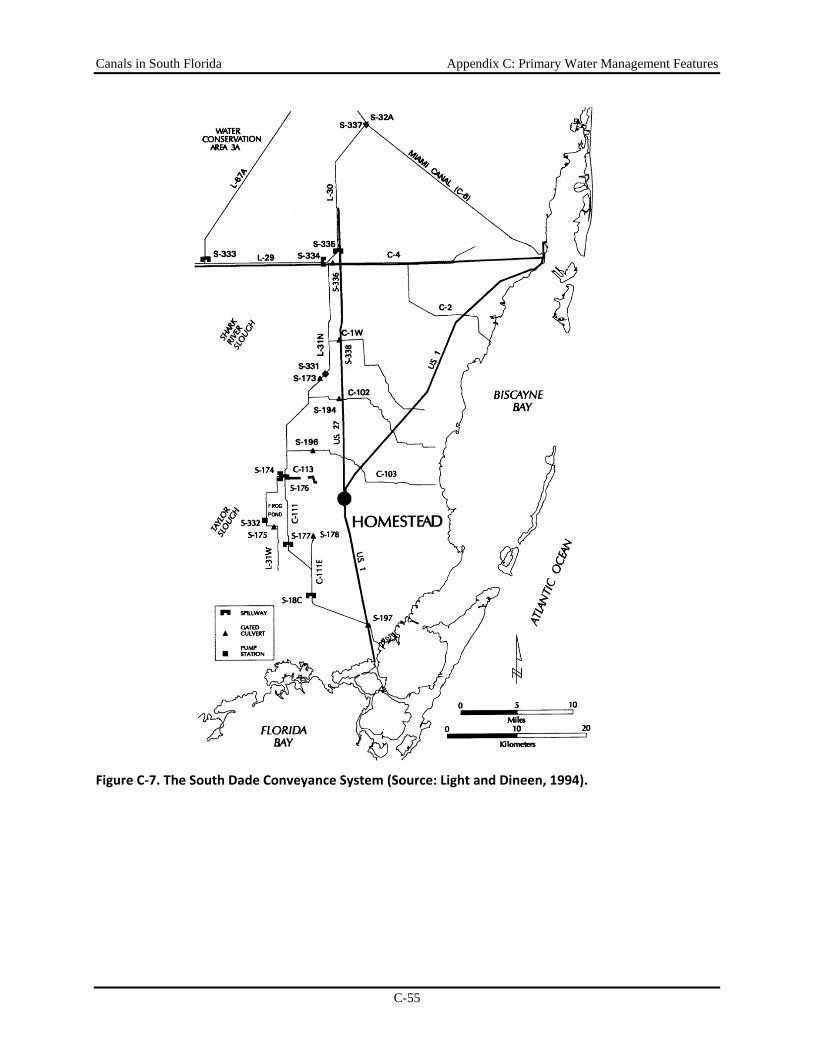
Canals in South Florida Appendix C: Primary Water Management Features
C-55
Figure C‐7. The South Dade Conveyance System (Source: Light and Dineen, 1994).
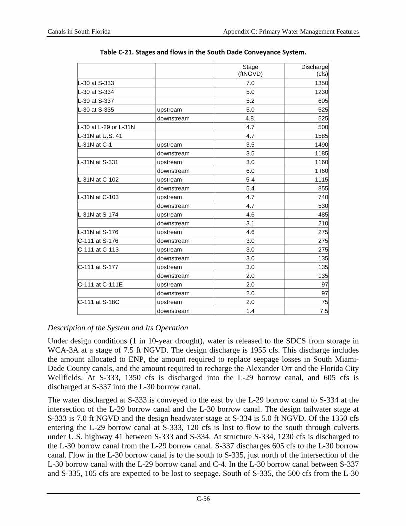
Canals in South Florida Appendix C: Primary Water Management Features
C-56
Table C‐21. Stages and flows in the South Dade Conveyance System.
Stage (ftNGVD)
Discharge (cfs)
L-30 at S-333 7.0 1350 L-30 at S-334 5.0 1230 L-30 at S-337 5.2 605 L-30 at S-335 upstream 5.0 525 downstream 4.8. 525 L-30 at L-29 or L-31N 4.7 500 L-31N at U.S. 41 4.7 1585 L-31N at C-1 upstream 3.5 1490 downstream 3.5 1185 L-31N at S-331 upstream 3.0 1160 downstream 6.0 1 I60 L-31N at C-102 upstream 5-4 1115 downstream 5.4 855 L-31N at C-103 upstream 4.7 740 downstream 4.7 530 L-31N at S-174 upstream 4.6 485 downstream 3.1 210 L-31N at S-176 upstream 4.6 275 C-111 at S-176 downstream 3.0 275 C-111 at C-113 upstream 3.0 275 downstream 3.0 135 C-111 at S-177 upstream 3.0 135 downstream 2.0 135 C-111 at C-111E upstream 2.0 97 downstream 2.0 97 C-111 at S-18C upstream 2.0 75 downstream 1.4 7 5
Description of the System and Its Operation
Under design conditions (1 in 10-year drought), water is released to the SDCS from storage in WCA-3A at a stage of 7.5 ft NGVD. The design discharge is 1955 cfs. This discharge includes the amount allocated to ENP, the amount required to replace seepage losses in South Miami-Dade County canals, and the amount required to recharge the Alexander Orr and the Florida City Wellfields. At S-333, 1350 cfs is discharged into the L-29 borrow canal, and 605 cfs is discharged at S-337 into the L-30 borrow canal.
The water discharged at S-333 is conveyed to the east by the L-29 borrow canal to S-334 at the intersection of the L-29 borrow canal and the L-30 borrow canal. The design tailwater stage at S-333 is 7.0 ft NGVD and the design headwater stage at S-334 is 5.0 ft NGVD. Of the 1350 cfs entering the L-29 borrow canal at S-333, 120 cfs is lost to flow to the south through culverts under U.S. highway 41 between S-333 and S-334. At structure S-334, 1230 cfs is discharged to the L-30 borrow canal from the L-29 borrow canal. S-337 discharges 605 cfs to the L-30 borrow canal. Flow in the L-30 borrow canal is to the south to S-335, just north of the intersection of the L-30 borrow canal with the L-29 borrow canal and C-4. In the L-30 borrow canal between S-337 and S-335, 105 cfs are expected to be lost to seepage. South of S-335, the 500 cfs from the L-30
Canals in South Florida Appendix C: Primary Water Management Features
C-57
borrow canal joins the 1230 cfs from the L-29 borrow canal. The combined discharge of 1730 cfs flows south in the L-31N borrow canal at a beginning stage of 4.7 ft NGVD. Of this flow, 145 cfs is discharged east through S 336 to C-4 for recharge of the Alexander Orr Wellfield east of C-2, 305 cfs is discharged to C-1, and 120 cfs is lost to seepage upstream of S-173. The headwater stage at S-173 is 3.0 ft NGVD.
During drought conditions, S-173 is closed and the pump station, S-331, is used to raise the tailwater stage at S-173 to 6.0 ft NGVD. Between S-173 and the intersection of the L-31N borrow canal with the L-31W borrow canal, 260 cfs is supplied to C-102 at a stage of 5.4 ft NGVD, 210 cfs is supplied to C-103 at a stage of 4.7 ft NGVD, and approximately 205 cfs is lost to seepage. Between the C-111 canal to the south and the L-31W borrow canal to the west, 485 cfs are left to be divided. By way of S-174, 210 cfs is discharged to the L-31W borrow canal. S-332 pumps 160 cfs to Taylor Slough. Any remaining flow not lost to seepage is discharged to the ENP through S-175. S-176 discharges 275 cfs to C-111 from the L-31N borrow canal. The tailwater stage at S-176 is 3.0 ft NGVD. South of S-176, 140 cfs is supplied to C-113 (to recharge the Florida City Wellfield), 60 cfs is lost to seepage and 75 cfs is discharged through S-18C at a stage of 2.0 ft NGVD. This flow is discharged to the panhandle portion of ENP through gaps in the south berm of C-111 between S-18C and S-197.
Canals in South Florida Appendix C: Primary Water Management Features
C-58
Lower West Coast Watersheds
Caloosahatchee River
Features of the current system The three structures and 41 miles of the C-43 Canal constitute the primary water management system within the Caloosahatchee basin, west of Lake Okeechobee. The Caloosahatchee River channel is 160 to 430 feet wide and 20 to 30 feet deep. The three structures are S-77 at Moore Haven, S-78 at Ortona located 15 miles west of S-77, and S-79 (also known as the W.P. Franklin Lock and Dam) near Ft. Myers, located 40 miles west of S-77. Each of these structures contains water control facilities as well as navigational locks (Figure C-8). The structures and canal improvements were authorized not only for navigation and flood protection, but also to eliminate undesirable salinity in the lower Caloosahatchee River, raise dry-weather water table levels, and provide water for agricultural irrigation from Lake Okeechobee storage.
The freshwater portion of the Caloosahatchee River watershed includes two primary basins. The upstream section of the river between S-78 and S-77 drains an area of about 338 square miles and water level in this part of the river is maintained at approximately 11 feet above mean sea level. Downstream, between S-78 and S-79, water level in the river is maintained at 3 feet above mean sea level. The drainage basin for this lower pool is 497 square miles. Land use in the Caloosahatchee Basins is mostly agriculture, with some low density residential communities and a small urban area near Labelle. The river, throughout its length, is used as a source of water for agricultural irrigation, including citrus, pasture, vegetables and flowers.
In the lower pool, especially areas west of Labelle, many oxbows of the original meandering river remain as shallow diversions from the main canal. Areas where the canal has been channelized are deep, have steep sides, and provide rather limited habitat for most fishes, benthic invertebrates and shoreline vegetation. By contrast, the remaining oxbows provide sheltered areas and a diversity of littoral habitats.
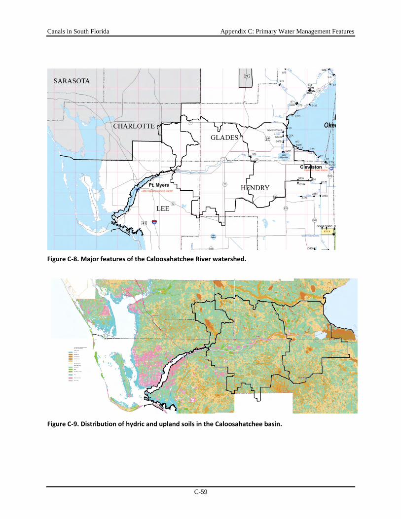
Canals in South Florida Appendix C: Primary Water Management Features
C-59
Figure C‐8. Major features of the Caloosahatchee River watershed.
Figure C‐9. Distribution of hydric and upland soils in the Caloosahatchee basin.
Canals in South Florida Appendix C: Primary Water Management Features
C-60
Collier County Collier County (Figure C-9) may be roughly divided into the Big Cypress Region, the Western Flatlands, and the Ten Thousand Islands. The area along the coast, west and north of the Big Cypress, and as far south as Gordon’s Pass, is part of the western flatlands. The elevation is higher than the Big Cypress. Around Immokalee the land is generally less than 25 feet relative to mean sea level. This area is characterized by a great number of marshes, swamps, and open water depressions, including Lake Trafford, the Corkscrew Marsh and the Okaloacoochee Slough.
Surface Hydrology and Hydraulic Systems The surface hydrology of the Big Cypress Basin is dictated by an extensive system of drainage canals and structures. This canal system separates the contributory drainage areas of the primary outfalls into eight major basins identified as follows:
• Golden Gate Canal
• Corkscrew-Cocohatchee
• District VI
• Henderson Creek
• Collier-Seminole
• Faka Union Canal
• Fakahatchee Strand
• Okaloacoochee Slough-Barron River
Primary Water Management System in Collier County
Of the eight basins identified above, three (Collier-Seminole, Fakahatchee Strand, and District VI ) do not contain primary water management canals or control structures The surface hydrology and primary drainage works of the other basins are described in the following sections based on earlier studies (primarily Dames and Moore, 1997; Collier County, 1990; and SFWMD, 1995). References in the following sections to “primary canals” are the canals that are maintained by the Big Cypress Basin (BCB); “secondary canals” are all other types of canals not maintained by BCB. Water Control Structures within the BCB are described in Table C-22 and characteristics of the canals are listed in Table C-23.
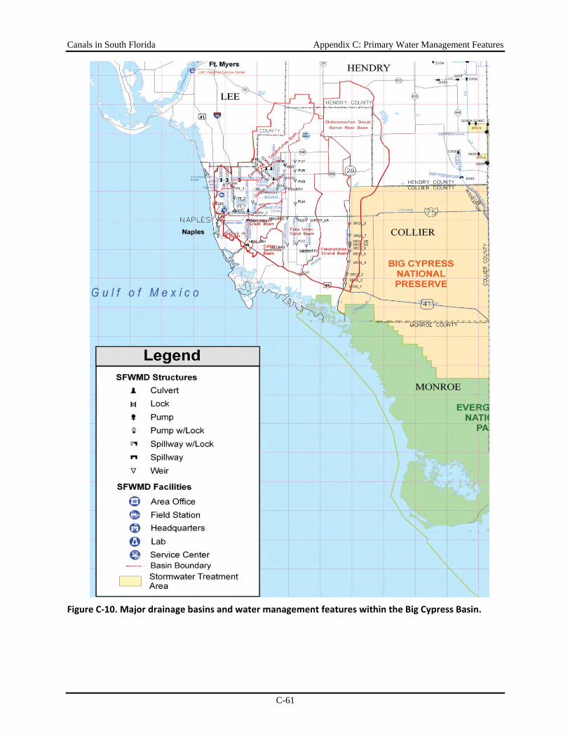
Canals in South Florida Appendix C: Primary Water Management Features
C-61
Figure C‐10. Major drainage basins and water management features within the Big Cypress Basin.
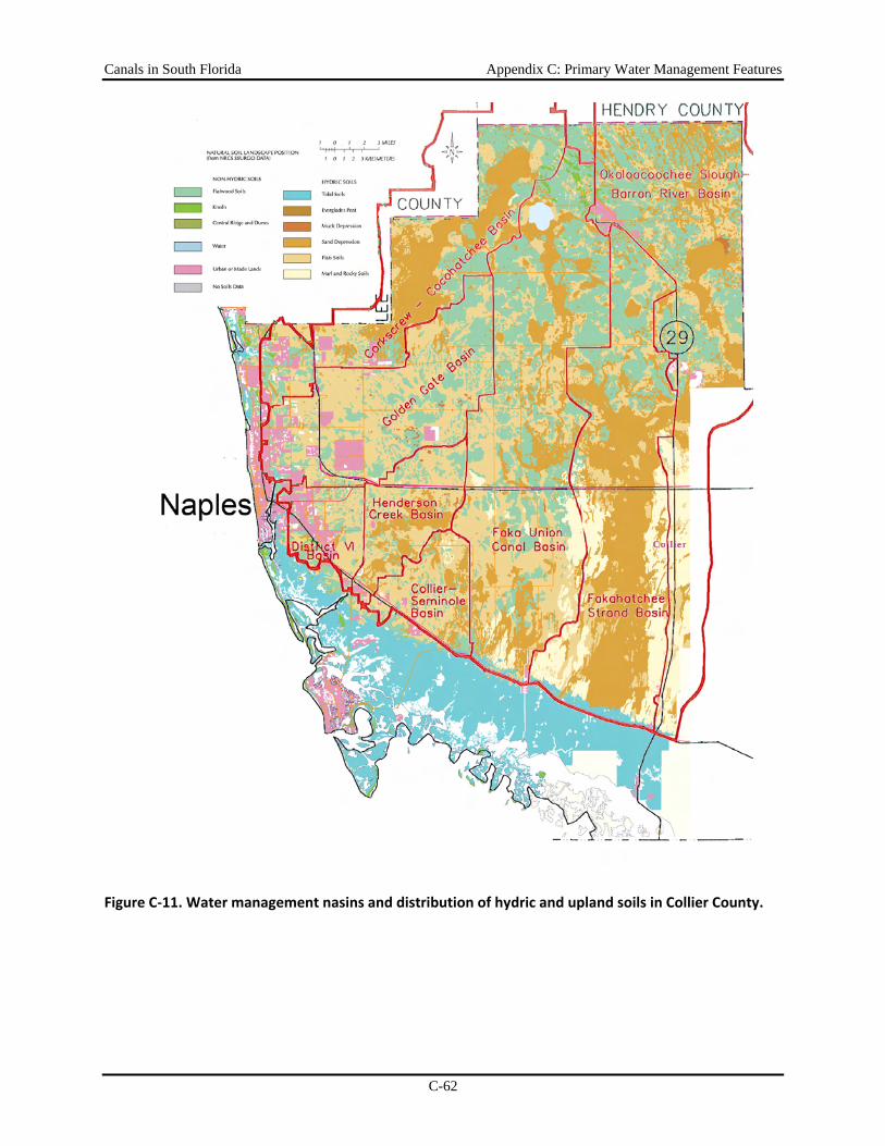
Canals in South Florida Appendix C: Primary Water Management Features
C-62
Figure C‐11. Water management nasins and distribution of hydric and upland soils in Collier County.
Canals in South Florida Appendix C: Primary Water Management Features
C-63
Golden Gate Canal Basin
The Golden Gate Canal Basin is located in the west-central portion of Collier County and was created by the construction of numerous canals by the Gulf America Corporation in the 1960s, primarily to drain the lands for residential development. Total basin area is approximately 108 square miles and contains a variety of land uses including agriculture, rural and urban residential, and commercial. There are several planned developments in various stages of completion, as well as the notable 4 square mile-residential development, Golden Gate City. The Golden Gate Canal drainage system has been separated into nine drainage sub-basins.
Main Golden Gate Canal Sub-basin is located in the southern and eastern portions of the Golden Gate Basin, and functions as the collector and discharge point for the Golden Gate Basin. Flow in the canal flow is generally to the southwest. Water control structures provide a step-down of the water level to prevent overdrainage of interior lands. Existing drainage facilities within this sub-basin consist of the main stem of Golden Gate Canal and its tributary network, namely, GG side branch, Cypress, Harvey, 1-75, Green, Corkscrew, Orangetree, 951 , and Airport Road, with seven SFWMD-operated water level control structures.
Cypress Canal Sub-basin is located in the northeast portion of the Golden Gate. The flow of water within this sub-basin is to the southwest. Existing drainage facilities within this sub-basin consist of the main stem of Cypress Canal and its tributaries, namely the Corkscrew and Curry canals with one SFWMD-operated water level control structure (CYPRESS-1).
Harvey Canal Sub-basin is located in the center of the Golden Gate Basin. Water flow within this sub-basin is to the south. Existing drainage facilities within this sub-basin consist of approximately 3.1 miles of primary canal and two water level control structures operated and maintained by Collier County.
I-75 Canal Sub-basin is located in the northwest portion of Golden Gate Basin. Water flow within this sub-basin is to the south. Water control structures provide a step-down of the water level to prevent overdrainage of interior lands. Existing drainage facilities within this sub-basin consist of the main stem of I-75 canal and its tributaries namely Harvey, Green, and northern Golden Gate City canals with three SFWMD-operated water level control structures: I-75-1, I-75-2, and 1-75-3. The 1-75 Canal discharges to the Main Golden Gate Canal a short distance upstream of GG-2.
Green Canal Sub-basin is located in the southern portion of the Golden Gate Basin. The flow of water within this sub-basin is to the west, discharging to the I-75 Canal. Existing drainage facilities within this sub-basin consist of the main stem of Green Canal and its tributaries, namely, the Harvey and the northern Golden Gate City canals.
Airport Road Canal South Sub-basin is located near the western end of the Main Golden Gate Canal, and is a drainage outlet for the lands located along Airport-Pulling Road between Vanderbilt Beach Road and Golden Gate Main Canal. The canal along Airport-Pulling Road has a drainage divide located at the Vanderbilt Beach Road intersection. Water in this sub-basin flows south and drains into the Main Golden Gate Canal a short distance upstream of the weir GG-1. Existing facilities in this sub-basin consist of approximately 5 miles of primary canal, one SFWMD-operated structure (CR-31S), and numerous culvert canal crossings
Corkscrew Canal Sub-basin is located in the northeastern portion of the Golden Gate Basin. Water within this sub-basin flows south and empties into Cypress Canal, just downstream of
Canals in South Florida Appendix C: Primary Water Management Features
C-64
structure GG-4. Existing drainage facilities in this sub-basin consist of approximately 7.6 miles of canal with numerous bridges and culverts that convey flows to the Cypress Canal system.
Orange Tree Canal Sub-basin is located in the northeast portion of Golden Gate Basin. Water in this sub-basin flows south into the Cypress Canal just upstream of structure GG-4. Existing drainage facilities in this sub-basin consist of approximately 3.4 miles of canal with one culvert structure providing conveyance of flows to the Cypress Canal system.
951 Canal Sub-basin is a small drainage area located east of County Road. The 951 canal sub-basin is approximately 7 miles long, flows south, and has several bridge structures.
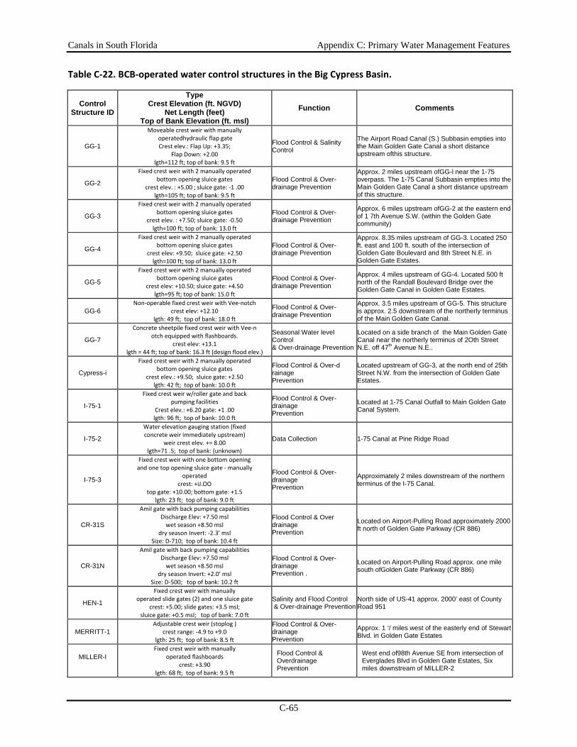
Canals in South Florida Appendix C: Primary Water Management Features
C-65
Table C‐22. BCB‐operated water control structures in the Big Cypress Basin.
Control Structure ID
Type Crest Elevation (ft. NGVD)
Net Length (feet) Top of Bank Elevation (ft. msl)
Function Comments
GG-1
Moveable crest weir with manually operatedhydraulic flap gate Crest elev.: Flap Up: +3.35;
Flap Down: +2.00 lgth=112 ft; top of bank: 9.5 ft
Flood Control & Salinity Control
The Airport Road Canal (S.) Subbasin empties into the Main Golden Gate Canal a short distance upstream ofthis structure.
GG-2
Fixed crest weir with 2 manually operated bottom opening sluice gates
crest elev. : +5.00 ; sluice gate: ‐1 .00 lgth=105 ft; top of bank: 9.5 ft
Flood Control & Over- drainage Prevention
Approx. 2 miles upstream ofGG-l near the 1-75 overpass. The 1-75 Canal Subbasin empties into the Main Golden Gate Canal a short distance upstream of this structure.
GG-3
Fixed crest weir with 2 manually operated bottom opening sluice gates
crest elev. : +7.50; sluice gate: ‐0.50 lgth=100 ft; top of bank: 13.0 ft
Flood Control & Over- drainage Prevention
Approx. 6 miles upstream ofGG-2 at the eastern end of 1 7th Avenue S.W. (within the Golden Gate community)
GG-4
Fixed crest weir with 2 manually operated bottom opening sluice gates
crest elev: +9.50; sluice gate: +2.50 lgth=100 ft; top of bank: 13.0 ft
Flood Control & Over- drainage Prevention
Approx. 8.35 miles upstream of GG-3. Located 250 ft. east and 100 ft. south of the intersection of Golden Gate Boulevard and 8th Street N.E. in Golden Gate Estates.
GG-5
Fixed crest weir with 2 manually operated bottom opening sluice gates
crest elev: +10.50; sluice gate: +4.50 lgth=95 ft; top of bank: 15.0 ft
Flood Control & Over- drainage Prevention
Approx. 4 miles upstream of GG-4. Located 500 ft north of the Randall Boulevard Bridge over the Golden Gate Canal in Golden Gate Estates.
GG-6 Non‐operable fixed crest weir with Vee‐notch
crest elev: +12.10 lgth: 49 ft; top of bank: 18.0 ft
Flood Control & Over- drainage Prevention
Approx. 3.5 miles upstream of GG-5. This structure is approx. 2.5 downstream of the northerly terminus of the Main Golden Gate Canal.
GG-7
Concrete sheetpile fixed crest weir with Vee‐n otch equipped with flashboards.
crest elev: +13.1 lgth = 44 ft; top of bank: 16.3 ft (design flood elev.)
Seasonal Water level Control & Over-drainage Prevention
Located on a side branch of the Main Golden Gate Canal near the northerly terminus of 2Oth Street N.E. off 47th Avenue N.E..
Cypress-i
Fixed crest weir with 2 manually operated bottom opening sluice gates
crest elev.: +9.50; sluice gate: +2.50 lgth: 42 ft; top of bank: 10.0 ft
Flood Control & Over-d rainage Prevention
Located upstream of GG-3, at the north end of 25th Street N.W. from the intersection of Golden Gate Estates.
I-75-1
Fixed crest weir w/roller gate and back pumping facilities
Crest elev.: +6.20 gate: +1 .00 lgth: 96 ft; top of bank: 10.0 ft
Flood Control & Over- drainage Prevention
Located at 1-75 Canal Outfall to Main Golden Gate Canal System.
I-75-2
Water elevation gauging station (fixed concrete weir immediately upstream)
weir crest elev. += 8.00 lgth=71 .5; top of bank: (unknown)
Data Collection 1-75 Canal at Pine Ridge Road
I-75-3
Fixed crest weir with one bottom opening and one top opening sluice gate ‐ manually
operated crest: +iJ.OO
top gate: +10.00; bottom gate: +1.5 lgth: 23 ft; top of bank: 9.0 ft
Flood Control & Over- drainage Prevention
Approximately 2 miles downstream of the northern terminus of the I-75 Canal.
CR-31S
Amil gate with back pumping capabilities Discharge Elev: +7.50 msl wet season +8.50 msl
dry season Invert: ‐2.3’ msl Size: D‐710; top of bank: 10.4 ft
Flood Control & Over drainage Prevention
Located on Airport-Pulling Road approximately 2000 ft north of Golden Gate Parkway (CR 886)
CR-31N
Amil gate with back pumping capabilities Discharge Elev: +7.50 msl wet season +8.50 msl
dry season Invert: +2.0’ msl Size: D‐500; top of bank: 10.2 ft
Flood Control & Over- drainage Prevention .
Located on Airport-Pulling Road approx. one mile south ofGolden Gate Parkway (CR 886)
HEN-1
Fixed crest weir with manually operated slide gates (2) and one sluice gate
crest: +5.00; slide gates: +3.5 msl; sluice gate: +0.5 msl; top of bank: 7.0 ft
Salinity and Flood Control & Over-drainage Prevention
North side of US-41 approx. 2000’ east of County Road 951
MERRITT-1 Adjustable crest weir (stoplog )
crest range: ‐4.9 to +9.0 lgth: 25 ft; top of bank: 8.5 ft
Flood Control & Over- drainage Prevention
Approx. 1 ‘/ miles west of the easterly end of Stewart Blvd. in Golden Gate Estates
MILLER-I
Fixed crest weir with manually operated flashboards
crest: +3.90 lgth: 68 ft; top of bank: 9.5 ft
Flood Control & Overdrainage Prevention
West end of98th Avenue SE from intersection of Everglades Blvd in Golden Gate Estates, Six miles downstream of MILLER-2
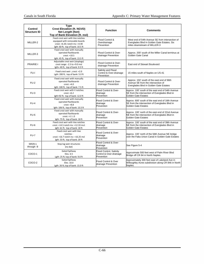
Canals in South Florida Appendix C: Primary Water Management Features
C-66
Control Structure ID
Type Crest Elevation (ft. NGVD)
Net Length (feet) Top of Bank Elevation (ft. msl)
Function Comments
MILLER-2
Fixed crest weir with Vee notches equipped with removable boards crest: +6.20; notch mv: +4.40 lgth: 60 ft; top of bank: 10.5 ft
Flood Control & Overdramage Prevention
West end of 54th Avenue SE from intersection of Everglades Blvd in Golden Gate Estates. Six miles downstream of MILLER-3
MILLER-3
Fixed crest weir with manually operated flashboards
crest: +10.5 lgth: 45 ft; top of bank: 13.5 ft
Flood Control & Over-drainage Prevention
Approx. 200’ south of the Miller Canal terminus at Golden Gate Canal
PRAIRIE-l Adjustable crest weir (stoplogs) crest range: ‐2.5 to +9.0 msl lgth= 40 ft; top of bank: 9.5 ft
Flood Control & Over-drainage Prevention East end of Stewart Boulevard
FU-l Fixed crest weir ; crest: +2.0 Lgth: 200 ft; top of bank: 5.0 ft
Salinity and Flood Control & Over-drainage Prevention
15 miles south of Naples on US-41
FU-2
Fixed crest weir with manually operated flashboards
crest: +4.0 lgth: 100 ft; top of bank: 7.5 ft
Flood Control & Over-drainage Prevention
Approx. 150’ south of the east end of 96th Avenue SE from the intersection of Everglades Blvd in Golden Gate Estates
FU-3 Fixed crest weir with V notches
crest: +6.2 lgth=92 ft; top of bank: 12.0 ft
Flood Control & Over-drainage Prevention
Approx. 100’ south of the east end of 54th Avenue SE from the intersection of Everglades Blvd in Golden Gate Estates
FU-4
Fixed crest weir with manually operated flashboards
crest: +8.8 lgth: 106 ft; top of bank: 13.5 ft
Flood Control & Over-drainage Prevention
Approx. 600’ south of the east end of 16th Avenue SE from the intersection of Everglades Blvd in Golden Gate Estates
FU-5
Fixed crest weir with manually operated flashboards
crest: +1 1 .0 lgth: 75 ft; top of bank: 18 ft
Flood Control & Over-drainage Prevention
Approx. 100’ north of the east end of 22nd Avenue NE from the intersection of Everglades Blvd in Golden Gate Estates
FU-6 Fixed crest weir with Vee notches crest: +14.5 notch inv: +12.33 ms1
lgth: 61 ft; top of bank: 18 ft
Flood Control & Over-drainage Prevention
Approx. 100’ south of the east end of 39th Avenue NE from the intersection of Everglades Blvd in Golden Gate Estates
FU-7
Fixed crest weir with Vee notches ‐
crest: +16.7 notch inv: +16.25 msl lgth: 33 ft; top of bank: 20 ft
Flood Control & Over-drainage Prevention
Approx. 100’ north of the 56th Avenue NE bridge over the Faka Union Canal in Golden Gate Estates
SR29-1 through -8
Stop log weir structures (no dat)
Flood Control & Over-drainage Prevention
See Figure 5-4
COCO-1 Gated Spiliway
Elev. 6.5 Lgth: 25 ft; top of bank: 9.0 ft
Flood Control, Salinity Control & Over-drainage Prevention
Approximate 500 feet west of Palm River Blvd Bridge off CR 84 in North Naples.
COCO-2 Gated Spiliway
Elev. 10.0 Lgth: 26 ft; top of bank: 15.0 ft
Flood Control & Over drainage Prevention
Approximately 300 feet east of Lakeland Ave in Willoughby Acres subdivision along CR 846 in North Naples.
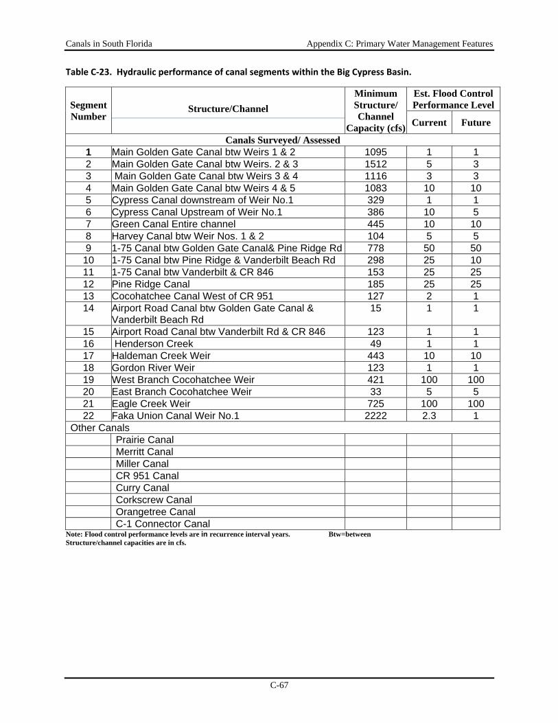
Canals in South Florida Appendix C: Primary Water Management Features
C-67
Table C‐23. Hydraulic performance of canal segments within the Big Cypress Basin.
Segment Number
Structure/Channel Minimum Structure/ Channel
Capacity (cfs)
Est. Flood Control Performance Level
Current Future
Canals Surveyed/ Assessed 1 Main Golden Gate Canal btw Weirs 1 & 2 1095 1 1 2 Main Golden Gate Canal btw Weirs. 2 & 3 1512 5 3 3 Main Golden Gate Canal btw Weirs 3 & 4 1116 3 3 4 Main Golden Gate Canal btw Weirs 4 & 5 1083 10 10 5 Cypress Canal downstream of Weir No.1 329 1 1 6 Cypress Canal Upstream of Weir No.1 386 10 5 7 Green Canal Entire channel 445 10 10 8 Harvey Canal btw Weir Nos. 1 & 2 104 5 5 9 1-75 Canal btw Golden Gate Canal& Pine Ridge Rd 778 50 50
10 1-75 Canal btw Pine Ridge & Vanderbilt Beach Rd 298 25 10 11 1-75 Canal btw Vanderbilt & CR 846 153 25 25 12 Pine Ridge Canal 185 25 25 13 Cocohatchee Canal West of CR 951 127 2 1 14 Airport Road Canal btw Golden Gate Canal &
Vanderbilt Beach Rd 15 1 1
15 Airport Road Canal btw Vanderbilt Rd & CR 846 123 1 1 16 Henderson Creek 49 1 1 17 Haldeman Creek Weir 443 10 10 18 Gordon River Weir 123 1 1 19 West Branch Cocohatchee Weir 421 100 100 20 East Branch Cocohatchee Weir 33 5 5 21 Eagle Creek Weir 725 100 100 22 Faka Union Canal Weir No.1 2222 2.3 1
Other Canals Prairie Canal Merritt Canal Miller Canal CR 951 Canal Curry Canal Corkscrew Canal Orangetree Canal C-1 Connector Canal
Note: Flood control performance levels are in recurrence interval years. Btw=between Structure/channel capacities are in cfs.
Canals in South Florida Appendix C: Primary Water Management Features
C-68
CorkscrewCocohatchee Basin
The Corkscrew-Cocohatchee basin is a large watershed in northern and northwestern Collier County and southeastern Lee County. The total basin has an approximate area of 174 to 194 square miles, containing a variety of land uses that include agriculture, urban and rural residential, and preservation/conservation areas. This basin includes six sub-basins, of which primary water management facilities are present within the Cocohatchee River, Pine Ridge, and Airport Road North canal sub-basins.
Cocohatchee River Canal Sub-basin includes the Corkscrew Swamp and is located in the center of the Corkscrew-Cocohatchee basin. It consists principally of the borrow canal excavated along the north side of county road 846 (Immokalee Road) and land immediately adjacent to this canal. Existing drainage facilities consist of approximately 12 miles of primary canal along the county road 846. Numerous bridge and culvert structures convey flows through the canal system. There are two operable water control structures in this sub-basin, COCO-1 and COCO-2
Pine Ridge Canal Sub-basin is at the southwest corner of the Corkscrew-Cocohatchee Basin and encompasses the northern half of Pine Ridge subdivision, as well as all lands between Pine Ridge Road and county road 846. The drainage area of this sub-basin is approximately 3 square miles. Existing drainage facilities consist of approximately 2.1 miles of primary canal with two water level control structures. The original canal that was excavated to provide a drainage outlet from the Pine Ridge subdivision to the Cocohatchee River has been modified by the Pelican Marsh Development.
Airport Road Canal North Sub-basin is adjacent to the West Branch Cocohatchee River sub-basin, providing a drainage outlet for the surrounding lands into the Cocohatchee River Main Canal to the north. The main feature of this sub-basin is the existing canal along the east side of Airport-Pulling Road (county road 31). A natural drainage divide located at the intersection of Vanderbilt Beach Road causes the water to drain both north and south from this point, creating two sub-basins for the one canal. There are approximately 2.0 miles of canal and one primary water level control structure, CR-31N, in the Airport Road Canal North sub-basin.
Henderson Creek Basin
The Henderson Creek basin is in the south-central portion of Collier County and has a total drainage area of approximately 48 square miles. Most of the basin consists of wetlands. The area is extremely flat and surface runoff naturally flows southwest to the Rookery Bay Estuary via Henderson Creek. There are four major constructed drainage facilities within this basin, consisting of approximately 7 miles of primary canal, 4 miles of secondary canal, one primary water level control structure (HEN CR-1), and one secondary water control structure.
Faka Union Canal Basin
The Faka Union Canal basin has a drainage area of approximately 185 square miles, located in central Collier County. This basin was created by the excavation of the Gulf America Corporation canal network in the 1960s and is separated from the Main Golden Gate Canal system during normal flow conditions by BCB operated water control structures. The primary drainage feature of the basin is the Faka Union Canal network comprised of the Miller, Faka Union, Merritt, and Prairie canals. The predominant land use in the basin is residential estates. An extensive roadway and canal system was installed throughout the basin during initial
Canals in South Florida Appendix C: Primary Water Management Features
C-69
construction to serve these areas. The northern half of the basin, north of Interstate 75, has undergone rapid residential development. The southern portion, south of Interstate 75, has little development to date. The basin includes four sub-basins.
Faka Union Canal Sub-basin is east of the Miller Canal sub-basin and extends from county road 846 to US-41. The Faka Union Canal is the primary drainage feature of this sub-basin. Flow is directed south through the center of Golden Gate Estates to the Faka Union Bay estuary via approximately 29.5 miles of primary canal and seven SFWMD operated weir structures (FU-l, FU-2, FU-3, FU-4, FU-5, FU-6, and FU-7). Existing drainage facilities also include several box culverts and bridges at various road crossings.
Miller Canal Sub-basin is the westernmost sub-basin of the Faka Union Canal basin. Historically, the sub-basin was part of a wetland system lying between the Henderson Creek and Fakahatchee Strand watersheds. Construction of the Miller Canal lowered the local water table, intercepting surface runoff, and cutting off the southwesterly sheet flow. Existing drainage facilities include approximately 19 miles of primary canal and 2 miles of secondary canal. The Miller Canal has its northern beginning at SFWMD operated weir structure MILLER-3, which separates Miller Canal from the Main Golden Gate Canal. The structure directs normal flows to the Golden Gate system, allowing overflow to Miller Canal during periods of high runoff. Two other primary structures, MILLER-2 and MILLER-1, are located along the main branch.
Merritt Canal Sub-basin is one of the easternmost sub-basins of the Faka Union Canal basin. Its headwaters are wetlands in the Lucky Lake Strand and Stumpy Strand within the Florida Panther National Wildlife Refuge. This sub-basin contains approximately 12 miles of primary canal and one primary structure, MERRITT-1, at the southern end of the sub-basin. South of this structure, the Merritt Canal accepts flows from the Prairie Canal.
Prairie Canal Sub-basin is one of the easternmost sub-basins of the Faka Union Canal basin. Existing drainage facilities include approximately 10 miles of primary canal and one primary weir, PRAIRIE-1, located in the southern end of the sub-basin. Prairie Canal discharges to Merritt Canal, which subsequently outfalls to the Faka Union Canal.
Okaloacoochee Slough-Barron River Basin
The Okaloacoochee Slough-Barron River basin is a 109-square mile watershed, consisting of wetlands and agricultural areas. This basin is located primarily in the south-central portion of Collier County, although the northern and easternmost portions of the basin lie in Hendry County. The western boundary of this basin is approximately one half mile west of state road 29. The northern portion contains the East Hinson Marsh, while the southern portion contains the Deep Lake Strand and several prairie lands. Most of the basin is located within the boundaries of Big Cypress National Preserve and the Big Cypress Wildlife Management Area. There is limited settlement in this basin, located in small communities along state road 29. Besides agriculture, there are a few active rock mining pits near state road 29.
The major drainage feature of the basin is the Main Barron River Canal. The 23.6-mile canal was excavated in the 1920s and contains eight stoplog control structures to prevent over-drainage of adjacent lands. The canal receives discharge from Okaloacoochee Slough to the north, as well as surface drainage from the wetlands within the basin. The canal eventually discharges into the Everglades estuary at the incorporated community of Everglades City. The basin contains four

Canals in South Florida Appendix C: Primary Water Management Features
C-70
identified sub-basins, of which only the Main Barron River Canal sub-basin, contains primary water management facilities.
Main Barron River Canal Sub-basin is the largest sub-basin within the Okaloacoochee Slough- Barron River basin. Existing drainage facilities include approximately 24 miles of canal and eight SFWMD operated control structures (SR29-1, 5R29-2, SR29-3, SR29-4, 5R29-5, 5R29-6, 5R29-7, and SR29-8). Numerous bridge crossings and culverts are also present.
Canals in South Florida Appendix C: Primary Water Management Features
C-71
References This Section Lists USACE and SFWMD documents that describe design, construction and operation of major features of the Central and Southern Florida Flood Control Project and works of the Big Cypress Basin. Blake, Nelson M. 1980. Land into Water - Water into Land. A history of water management in Florida.
University Presses of Florida. Tallahassee, Florida. 344 pp.
Bottcher, A. B. and F. T. Izuno. 1992. Everglades Agricultural Area: Water, Soil, Crop and Environmental Management, University Presses of Florida, Gainesville, 479 pp.
Burns, S., C. Cassagnol, P. Millar, D. Nealon, R.E Santee. P. Trimble, and P. Walker, 1982. Southwest Broward County Study. South Florida Water Management District, West Palm Beach, FL. Tech. Memorandum. October 1982.
Camp, Dresser, and McKee, Inc. 1985. C-25 Canal Basin Hydrologic Study. June 1985. Fort Lauderdale, FL.
Central and Southern Florida Flood Control District, 1958. The Water Control Program Proposed for the Upper Kissimmee Basin. West Palm Beach. FL Technical Memorandum July 1958 (revised Sp t 1963
Central and Southern Florida Flood Control District, 1959. A Study of Installation of Project Works in the Upper Kissimmee Lakes Area Prior to Completion of C-38. Planning and Administrative Services Department, Planning-Engineering Section. Dec. 1959.. West Palm Beach, FL.
Central and Southern Florida Flood Control District, 1971. Operational Analysis of a Flood in the Lower Kissimmee River Basin. Engineering Department, Central and Southern Florida Flood Control District. July 1971.
Central and Southern Florida Flood Control District, 1972. Statement on the Kissimmee Basin Project Presented to the Governor and Cabinet. December 12, 1972. Tallahassee, FL.
Central and Southern Florida Flood Control District, 1975. Lake Okeechobee-Kissimmee Basin Proposals for Management Action. West Palm Beach. FL. March 1975
Central and Southern Florida Flood Control District, 1979. Kissimmee River. Florida. Reconnaissance Report (Stage 1). West Palm Beach. FL.
Central and Southern Florida Flood Control District, 1989. Flood Control and Other Purposes. Part II. Supplement 20 (Revised). General Design Memorandum.
Cooper, R. M. 1989. An Atlas of the Everglades Agricultural Area Surface Water Management Basins. South Florida Water Management District, Wert Palm Beach. FL. Tech. Memorandum. September 1989.
Cooper, R. M. and J. Lane, 1987. An Atlas of Eastern Broward County Surface Water Management Basins. South Florida Water Management District, West Palm Beach. FL. Tech. Memorandum. November 1987.
Cooper, R. M. and J. Lane, 1987. An Atlas of Eastern Dade County Surface Water Management Basins. South Florida Water Management District, West Palm Beach, FL. Tech. Memorandum. October 1987.
Cooper, R. M. and J. Lane, 1988. An Atlas of Eastern Palm Beach County Surface Water Management Basins. South Florida Water Management District. West Palm Beach, FL. Tech. Memorandum, June 1988.
Canals in South Florida Appendix C: Primary Water Management Features
C-72
Cooper, R. M. and J. Roy. 1991. An Atlas of Surface Water Management Basins in the Everglades: The Water Conservation Areas and Everglades National Park, South Florida Water Management District, West Palm Beach, 88 pp.
Cooper, R. M. and Ray Santee. 1988. An Atlas of Martin County Surface Water Management Basins. South Florida Water Management District, West Palm Beach, FL. Tech. Memorandum, November 1988.
Cooper, R. M. and Terry W. Ortel. 1988. An Atlas of St. Lucie County Surface Water Management Basins. South Florida Water Management District. West Palm Beach, FL. Tech. Memorandum, November 1988.
Cornwell, G.. R.L. Downing, A.R. Marshall, and J. N. Layne. 1970. Report of the Special Study Team on the Florida Everglades. South Florida Water Management District, West Palm Beach. FL. Tech. Memorandum, August 1970.
Florida State House of Representatives. 1991. Marjory Stoneman Douglas Everglades Protection Act. Florida State Legislature. Tallahassee, Florida.
Lane, J. T. McCann. S.T. Lin. 1979. Floodplain Management Studies of the Shingle Creek Basin. Dept. of Environmental Regulation. Technical Series Vol. 2 No. 2. South Florida Water Management District, West Palm Beach, FL
Mierau, R. 1974. Supplemental Water Use in the Everglades Agricultural Area. South Florida Water Management District, West Palm Beach, FL. Tech. Publication 74-4. 46 pp.
Mierau, R. 1988. Hydrologic Characteristics of the Kissimmee River Floodplain Boney Marsh Experimental Area. South Florida Water Management District, West Palm Beach. FL. Tech. Memorandum, September 1988.
Mierau, R. and E. C. Lane. 1981. Preliminary Assessments of Drainage Impacts in the East Everglades Area of Dade County. South Florida Water Management District, West Palm Beach. FL. Tech.
Mierau, R., R.L. Taylor, and W.V. Storch. 1974. Surface Water Availability in the St. Lucie County Area. South Florida Water Management District, Memorandum Report. July 1974.
Mierau, R. R. Taylor, N. Khanal, W, Storch, and G. E. Dail. 1975. Water Availability in the Dade County Agricultural Area. South Florida Water Management District, Tech. Memorandum. July 1975.
Smith, B. 1848. Reconnaissance of the Everglades. Report to Secretary of the United States Treasury, Senate Report 242, 30th Congress, First session, August 12, 1848.
Smith, L. 1980. The challenge of water management. South Florida Water Management District In Depth Report 5(1). West Palm Beach, Florida. 8 pp. March.
South Florida Water Management District, (Unpublished) Structures Operation Manual. Operations Division. West Palm Beach. PL. Unpublished material.
South Florida Water Management District, 1971. Some Aspects of the Hydrology of Conservation Area No. 3. Resource Planning Department. West Palm Beach. FL. Tech. Memorandum. June 1971.
South Florida Water Management District, 1974. Response to the United States Army, Corps of Engineers Draft Survey Review Report on the Hillsboro Canal Basin. Resource Planning Department. South Florida Water Management District, Technical Memorandum. August 1984.
South Florida Water Management District, 1976. Water Management Plan for the Western C-9 Basin. Resource Planning Department. South Florida Water Management District, Technical Memorandum. June 1971.
Canals in South Florida Appendix C: Primary Water Management Features
C-73
South Florida Water Management District, 1978. General and Procedural Information, PERMIT INFORMATION MANUAL, VOLUME I. Resource Control Department South Florida Water Management District, West Palm Beach. FL.
South Florida Water Management District, 1980. Water Use and Supply Development Plan. Summary Status Report--Upper East Coast. Resource Planning Department South Florida Water Management District, West Palm Beach, FL. Tech. Memorandum, October 1980.60 pp.
South Florida Water Management District, 1982. An Analysis of Water Supply Backpumping for the Lower East Coast Planning Area. South Florida Water Management District, West Palm Beach. FL. Tech. Memorandum. February 1982.
South Florida Water Management District, 1983a. District Rules, Regulation, and Legislation. PERMIT INFORMATION MANUAL. VOLUME II. Resource Control Department. South Florida Water Management District, West Palm Beach. FL.
South Florida Water Management District, 1983b. Report to the United States Army Corps of Engineers Requesting a Review of Central and Southern Florida Flood Control Project Facilities in the C-111 Basin. Dade County, Florida. South Florida Water Management District, West Palm Beach, FL. Letter report, February, 1983.
South Florida Water Management District, 1984a. North New River Backpumping Water Quality Backpumping Water Quality Impact Study Report No. 1 Preconstruction and Initial Operation. Water Chemistry Division.. South Florida Water Management District, West Palm Beach, FL. Tech. Memorandum, March 1984.
South Florida Water Management District, 1984b. . Water Management Planning for the Western C-51 Basin. South Florida Water Management District, Resource Planning Department. West Palm Beach, FL. Tech. Memorandum. March 1984.
South Florida Water Management District, 1985a. Management of Water Use, PERMIT INFORMATION MANUAL, VOLUME Ill. Resource Control Department. South Florida Water Management District, West Palm Beach, FL.
South Florida Water Management District, 1986a. Criteria Manual for Use of District works. PERMIT INFORMATION MANUAL. VOLUME V. Resource Control Department, South Florida Water Management District, West Palm Beach. FL.
South Florida Water Management District, 1986b. DRAFT Southeast Martin County Resource Analysis. South Florida Water Management District, Resource Control Department. West Palm Beach, FL. Tech. Memorandum, October 1986. 38pp.
South Florida Water Management District, 1987b. Management and Storage of Surface Waters, PERMIT INFORMATION MANUAL, VOLUME IV. Resource Control Department. South Florida Water Management District, West Palm Beach, FL
Storch, W.V. 1972a. Examination of the Effects of C-51 Backpumping on the Water Regime of the Conservation Areas. South Florida Water Management District, West Palm Beach, FL. Tech. Memorandum. June 1972.
Storch. W.V. 1975b. Report on Investigation of Back-Pumping Reversal and Alternative Water Retention Sites (Miami Canal and North New River Canal Basins Everglades Ag. Area. South Florida Water Management District, West Palm Beach, FL. Tech. Memorandum, December. 1975.
U. S. Army Corps of Engineers, 1951a. Partial Definite Project Report, Central and Southern Florida Project for Flood Control and Other Purposes, Part I, Agricultural and Conservation Areas (with Preliminary Information on Lake Okeechobee and Principal Outlets), July 10, 1951. U.S. Army Engineer District, Jacksonville, Corps of Engineers. Jacksonville. Florida.
Canals in South Florida Appendix C: Primary Water Management Features
C-74
U. S. Army Corps of Engineers, 1951b. Partial Definite Project Report. Central and Southern Florida Project for Flood Control and Other Purposes. Part I. Agricultural and Conservation Areas, Supplement 2, Agricultural Levees, December 29. 1951. U.S. Army Engineer District, Jacksonville. Corps of Engineers, Jacksonville, Florida.
U. S. Army Corps of Engineers, 1952a. Partial Definite Project Report, Central and Southern Florida Project for Flood Control and Other Purposes, Part I, Agricultural and Conservation Areas, Supplement 3, Design Memorandum --Pumping Station 5A, January 19, 1952. U.S. Army Engineer District, Jacksonville, Corps of Engineers. Jacksonville. Florida.
U. S. Army Corps of Engineers, 1952b. Partial Definite Project Report, Central and Southern Florida Project for Flood Control and Other Purposes, Part I, Agricultural and Conservation Areas, Supplement 4, Structural Design, January 20, 1952. US. Army Engineer District. Jacksonville, Corps of Engineers, Jacksonville, Florida.
U. S. Army Corps of Engineers, 1952c. Partial Definite Project Report, Central and Southern Florida Project for Flood Control and Other Purposes, Part I, Agricultural and Conservation Areas. Supplement 6, Design Memorandum --Gates and Operating Machinery of Control Structures 5A-E, 5A-W, and 5A-S (Auxiliary Structures to Pump Station 5A), March 5, 1952. U.S. Army Engineer District. Jacksonville, Corps of Engineers, Jacksonville, Florida.
U. S. Army Corps of Engineers, 1952d. Partial Definite Project Report, Central and Southern Florida Project for Flood Control and Other Purposes, Part V, Coastal Areas South of St. Lucie Canal. Supplement 6, Design Memorandum --Pumping Station 9. November 28, 1952. U.5. Army Engineer District, Jacksonville, Corps of Engineers, Jacksonville, Florida.
U. S. Army Corps of Engineers, 1952e. Partial Definite Project Report. Central and Southern Florida Project for Flood Control and Other Purposes. Part V, Coastal Areas South of St. Lucie Canal, Supplement 8, Design Memorandum --Canals 12 and 13, Control Structures 33 and 36. October 31, 1952. US. Army Engineer District, Jacksonville. Corps of Engineers, Jacksonville. Florida.
U. S. Army Corps of Engineers, 1953a Partial Definite Project Report, Central and Southern Florida Project for Flood Control and Other Purposes. Part I, Agricultural and Conservation Areas, Supplement 10, Design Memorandum --Pumping Station 6. May 27. 1953. U.S. Army Engineer District, Jacksonville, Corps of Engineers. Jacksonville. Florida.
U. S. Army Corps of Engineers, 1953b. Partial Definite Project Report, Central and Southern Florida Project for Flood Control and Other Purposes. Part I. Agricultural and Conservation Areas. Supplement 8, Design Memorandum --Development of a Plan of Protection for the Agricultural Area, February 6, 1953. U.S. Army Engineer District. Jacksonville. Corps of Engineers, Jacksonville. Florida.
U. S. Army Corps of Engineers, 1953c. Partial Definite Project Report, Central and Southern Florida Project for Flood Control and Other Purposes. Part I. Agricultural and Conservation Areas, Supplement 9, Design Memorandum --Hydrology and Hydraulics of the Hillsboro Canal and Related Works (L-14. L-15, 5-2, and 5-6). June 8, 1953 US. Army Engineer District, Jacksonville, Corps of Engineers, Jacksonville, Florida.
U. S. Army Corps of Engineers, 1953d. Partial Definite Project Report, Central and Southern Florida Project for Flood Control and Other Purposes, Part I. Agricultural and Conservation Areas. Supplement 11, Design Memorandum --Hydrology and Hydraulic Design of West Palm Beach Canal and Related Works (L-10 and L-12). June 17. 1953. U.S. Army Engineer District, Jacksonville. Corps of Engineers, Jacksonville. Florida.
U. S. Army Corps of Engineers, 1953e. Partial Definite Project Report, Central and Southern Florida Project for Flood Control and Other Purposes, Part I, Agricultural and Conservation Areas,
Canals in South Florida Appendix C: Primary Water Management Features
C-75
Supplement 12, Design Memorandum --Hillsboro Canal (Levees 14 and 15). July 15, 1953. U.5. Army Engineer District. Jacksonville, Corps of Engineers. Jacksonville, Florida.
U. S. Army Corps of Engineers, 1953f. Partial Definite Project Report, Central and Southern Florida Project for Flood Control and Other Purposes. Part I, Agricultural and Conservation Areas, Supplement 13, Design Memorandum --Hydrology and Hydraulic Design of the North New River Canal and Related Works (L-18, L-19, 1-20, and 5-7), July 6, 1953. U.S. Army Engineer District, Jacksonville. Corps of Engineers, Jacksonville. Florida.
U. S. Army Corps of Engineers, 1953g. Partial Definite Project Report, Central and Southern Florida Project for Flood Control and Other Purposes, Part I, Agricultural and Conservation Areas. Supplement 14, Design Memorandum --Hydrology and Hydraulic Design of the Miami Canal and Related Works (L-23,L-24, L-25, 5-3, and 5-8), August 17, 1953. U.S. Army Engineer District, Jacksonville. Corps of Engineers, Jacksonville. Florida.
U. S. Army Corps of Engineers, 1953h. Partial Definite Project Report, Central and Southern Florida Project for Flood Control and Other Purposes, Part I, Agricultural and Conservation Areas, Supplement 15, Design Memorandum --Pumping Station 2, July 29. 1953. U.S. Army Engineer District, Jacksonville. Corps of Engineers, Jacksonville, Florida.
U. S. Army Corps of Engineers, 1953i. Partial Definite Project Report, Central and Southern Florida Project for Flood Control and Other Purposes, Part I, Agricultural and Conservation Areas, Supplement 16, Design Memorandum --West Palm Beach Canal (Levees 10 and 12). October 15. 1953. U.S. Army Engineer District, Jacksonville, Corps of Engineers. Jacksonville. Florida.
U. S. Army Corps of Engineers, 1953j. Partial Definite Project Report, Central and Southern Florida Project for Flood Control and Other Purposes, Part I. Agricultural and Conservation Areas, Supplement 17, Design Memorandum --Pumping Station 3, October 30, 1953. U.S. Army Engineer District. Jacksonville, Corps of Engineers, Jacksonville, Florida.
U. S. Army Corps of Engineers, 1953k. Partial Definite Project Report, Central and Southern Florida Project for Flood Control and Other Purposes. Part I, Agricultural and Conservation Areas. Supplement 18, Design Memorandum --Revision of Hydrology and Hydraulic Design of the West Palm Beach. Hillsboro. North New River, and Miami Canals. November 16, 1953. U.S. Army Engineer District, Jacksonville, Corps of Engineers. Jacksonville, Florida.
U. S. Army Corps of Engineers, 1953l. Partial Definite Project Report, Central and Southern Florida Project for Flood Control and Other Purposes. Part I, Agricultural and Conservation Areas. Supplement 19, Design Memorandum --North New River Canal (Levees 20, 19, and 18). December 1, 1953. U.S. Army Engineer District, Jacksonville, Corps of Engineers, Jacksonville, Florida.
U. S. Army Corps of Engineers, 1954a. Partial Definite Project Report, Central and Southern Florida Project for Flood Control and Other Purposes, Part I, Agricultural and Conservation Areas, Supplement 20, Design Memorandum --Miami Canal (Levees 25, 24, and 23), February 5. 1954. U.S. Army Engineer District, Jacksonville, Corps of Engineers, Jacksonville, Florida.
U. S. Army Corps of Engineers, 1954b. Partial Definite Project Report, Central and Southern Florida Project for Flood Control and Other Purposes. Part I, Agricultural and Conservation Areas. Supplement 21, Design Memorandum --Agricultural Area Levees, Levees 4 (East), 5, and 6, November 1, 1954. U.5. Army Engineer District, Jacksonville, Corps of Engineers, Jacksonville, Florida.
U. S. Army Corps of Engineers, 1954c. Partial Definite Project Report, Central and Southern Florida Project for Flood Control and Other Purposes, Part I, Agricultural and Conservation Areas, Supplement 22, Design Memorandum --Agricultural Area Levees, Levees 2, 3, and 4 (West),
Canals in South Florida Appendix C: Primary Water Management Features
C-76
November 19, 1954. U.S. Army Engineer District. Jacksonville, Corps of Engineers. Jacksonville, Florida.
U. S. Army Corps of Engineers, 1954d. Partial Definite Project Report. Central and Southern Florida Project for Flood Control and Other Purposes, Part I, Agricultural and Conservation Areas, Supplement 24, Design Memorandum --Pumping Station 7, December 13, 1954. U.S. Army Engineer District, Jacksonville. Corps of Engineers, Jacksonville. Florida.
U. S. Army Corps of Engineers, 1955. Partial Definite Project Report, Central and Southern Florida Project for Flood Control and Other Purposes, Part I. Agricultural and Conservation Areas, Supplement 23. Design Memorandum --Levee 39, Spillway 10, June 20, 1955 U.S Army Engineer District, Jacksonville, Corps of Engineers, Jacksonville. Florida.
U. S. Army Corps of Engineers, 1956a. Central and Southern Florida Project for Flood Control and Other Purposes, Part II, Kissimmee Basin and Related Areas. Supplement 3 --Design Memorandum, Lake lstokpoga Indian Prairie Area (Canals 39A, 40,41 and Structu res 70, 71, 72, 75, 82), May 1956. U.S. Army Corps of Engineers, Jacksonville. FL.
U. S. Army Corps of Engineers, 1956b. Central and Southern Florida Project for Flood Control and Other Purposes, Part II, Kissimmee River Basin and Related Areas, Supplement 6, Design Memorandum --Plan of Regulation for Lake Istokpoga, October 12, 1956. U.S. Army Corps of Engineers, Jacksonville, FL.
U. S. Army Corps of Engineers, 1956c. Central and Southern Florida Project for Food Control and Other Purposes: Part II: Kissimmee River Basin and Related Areas. Supplement 5. General Design Memorandum, Kissimmee River Basin. U. S. Army Corps of Engineers, Jacksonville, FL. Oct. 1956
U. S. Army Corps of Engineers, 1957a. Central and Southern Florida Project for Flood Control and Other Purposes, Part I, Agricultural and Conservation Areas, Supplement 26, Design Memorandum --Pumping Station 8, May 27, 1957. U.S. Army Engineer District, Jacksonville, Corps of Engineers, Jacksonville, Florida.
U. S. Army Corps of Engineers, 1957b. Central and Southern Florida Project for Flood Control and Other Purposes, Part I. Agricultural and Conservation Areas, Supplement 25. General Design Memorandum --Plan of Regulation for Conservation Area No. 1, November 29. 1957. U.S. Army Engineer District, Jacksonville, Corps of Engineers, Jacksonville. Florida.
U. S. Army Corps of Engineers, 1958a Central and Southern Florida Project for Flood Control and Other Purposes, Part ll, Kissimmee River Basin and Related Areas, Supplement 7, Detailed Design Memorandum --Canal 41A (Slough and Stub Canals) and Structures 66, 68, 83, and 84, January 22, 1958. U.S. Army Corps of Engineers, Jacksonville, FL.
U. S. Army Corps of Engineers, 1958b. Central and Southern Florida Project for Flood Control and Other Purposes, Part I. Agricultural and Conservation Areas, Supplement 27, General Design Memorandum --Plan OF Regulation, February 28, 1958. US. Army Engineer District, Jacksonville, Corps of Engineers. Jacksonville, Florida.
U. S. Army Corps of Engineers, 1958c. Central and Southern Florida Project for Flood Control and Other Purposes. Part V, Coastal Areas South of St. Lucie Canal. Supplement 23, Design Memorandum --Canal 14 and Control Structures 37A. 37B, and 38A. May 5. 1958. U.S. Army Engineer District, Jacksonville, Corps of Engineers, Jacksonville, Florida.
U. S. Army Corps of Engineers, 1958d. Central and Southern Florida Project for Flood Control and Other Purposes, Part I, Agricultural and Conservation Areas, Supplement 23 (Revision). Design Memorandum --Levee 39, Spillway 10, and Interim Modifications to Levees 7 and 40, July 1958. U.S. Army Engineer District, Jacksonville, Corps of Engineers. Jacksonville, Florida.
Canals in South Florida Appendix C: Primary Water Management Features
C-77
U. S. Army Corps of Engineers, 1958e Central and Southern Florida Project for Flood Control and Other Purposes, Pan I, Agricultural and Conservation Areas, Supplement 28, Detailed Design Memorandum --L-38 (East), Section 1, December 23, 1958. U S. Army Engineer District, Jacksonville, Corps of Engineers, Jacksonville, Florida.
U. S. Army Corps of Engineers, 1959a. Central and Southern Florida Project for Flood Control and Other Purposes, Part 12, Lake Okeechobee and Outlets, Supplement 7. General and Detailed Design Memorandum --Lake Okeechobee Northwest Levees (Levees 48.49, and 50; Interceptor dikes, 59, 60 and. 61; and Pumping Stations 127, 128, 129, 130, 131, and 132), May 29, 1959. U.S. Army Corps of Engineers, Jacksonville, FL.
U. S. Army Corps of Engineers, 1959b. Central and Southern Florida Project for Flood Control and Other Purposes, Part V. Coastal Areas South of St. Lucie Canal, Supplement 27, Design Memorandum --Canal 9 (Section 5) and Control Structure 30, April 20, 1959. U.S. Army Engineer District, Jacksonville. Corps of Engineers, Jacksonville, Florida.
U. S. Army Corps of Engineers, 1959c. Central and Southern Florida Project For Flood Control and Other Purposes, Part I, Agricultural and Conservation Areas. Supplement 29. Detailed Design Memorandum --L-38. Section 2 (Raising U.S. Highway 27 Between S-11A and S-11C). July 28, 1959. US. Army Engineer District, Jacksonville, Corps of Engineers, Jacksonville, Florida.
U. S. Army Corps of Engineers, 1959d. Central and Southern Florida Project for Flood Control and Other Purposes, Part I, Agricultural and Conservation Areas, Supplement 30, General Design Memorandum --L-28 (Section 2) and Related Works, September 15, 1959. U.S. Army Engineer District. Jacksonville. Corps of Engineers, Jacksonville, Florida.
U. S. Army Corps of Engineers, 1959e. Central and Southern Florida Project for Flood Control and Other Purposes, Part I, Agricultural and Conservation Areas, Supplement 31, Detailed Design Memorandum --L-350 and 38 (Section 3). Spoil Islands- L-350 and 38 (Section 2) and Control Structure 38, October 13. 1959. U.S. Army Engineer District, Jacksonville, Corps of Engineers, Jacksonville, Florida.
U. S. Army Corps of Engineers, 1960a. Central and Southern Florida Project for Flood Control and Other Purposes. Part I. Agricultural and Conservation Areas, Supplement 33, General Design Memorandum --Conservation Area 3, July 22. 1960. U.S. Army Engineer District, Jacksonville, Corps of Engineers, Jacksonville. Florida.
U. S. Army Corps of Engineers, 1960b. Central and Southern Florida Project for Flood Control and Other Purposes. Part I, Agricultural and Conservation Areas, Supplement 34, Detailed Design Memorandum --Levees 67A and 29, Section 3, and Control Structure 151, September 30. 1960. U.S. Army Corps of Engineers, Jacksonville, Florida.
U. S. Army Corps of Engineers, 1960c. Central and Southern Florida Project for Flood Control and Other Purposes, Part I, Agricultural and Conservation Areas, Supplement 35, Detailed Design Memorandum --Levee 29, Sections 1 and 2, and Control Structures 12A. 120. 12C. 12D. 12E. and 14, November 7, 1960. U.S. Army Engineer District, Jacksonville, Corps of Engineers. Jacksonville, Florida.
U. S. Army Corps of Engineers, 1961a. Boggy Creek Basin, Orange and Osceola Counties. Florida. U. S. Army Corps of Engineers. Jacksonville. FL. April 1961
U. S. Army Corps of Engineers, 1961b. Central and Southern Florida Project for Flood Control and Other Purposes, Part IV, Lake Okeechobee and Outlets, Supplement 14, Detailed Design Memorandum --Herbert Hoover Dike, Levees D-I, D-2 (Part), and D-3 (Part), May 26, 1961. U. S. Army Corp of Engineers, Jacksonville, Florida.
Canals in South Florida Appendix C: Primary Water Management Features
C-78
U. S. Army Corps of Engineers, 1961c. Central and Southern Florida Project for Flood Control and Other Purposes. Part I. Agricultural and Conservation Areas, Supplement 36, Hydrologic and Meteorologic Gaging Programs, Conservation Area No. 3, May 31, 1961. U.S. Army Engineer District, Jacksonville, Corps of Engineers, Jacksonville, Florida.
U. S. Army Corps of Engineers, 1961d. Central and Southern Florida Project for Flood Control and Other Purposes. Part 11, Kissimmee River Basin and Related Areas, Supplement 9. Detailed Design Memorandum --Canal 38. Section 1 (Kissimmee River) and Control Structure S-65E. June --21, 1961. U.S. Army Corps of Engineers, Jacksonville, FL.
U. S. Army Corps of Engineers, 1961e. Central and Southern Florida for Food Control and Other Purposes: Part II: Kissimmee River Basin and Related Areas, Supplement 10. Detail Design Memorandum, Canals 31 and 35 (St. Cloud and South Port Canals) and Control Structures 59 and 21. U. S. Army Corps of Engineers. Jacksonville. FL. June 1961
U. S. Army Corps of Engineers, 1962a. Central and Southern Florida Project for Flood Control and Other Purposes, Part I, Agricultural and Conservation Areas, Supplement 32, Detailed Design Memorandum --L-28. Sections 2, 3, and 5, March 2, 1962. U.5. Army Engineer District, Jacksonville, Corps of Engineers, Jacksonville, Florida.
U. S. Army Corps of Engineers, 1962b. Central and Southern Florida Project for Flood Control and Other Purposes. Part I, Agricultural and Conservation Areas, Supplement 37, Detailed Design Memorandum --Structures 248, 31, and S-150 (Conservation Area No. 3), April 27, 1962. U.5. Army Engineer District, Jacksonville, Corps of Engineers, Jacksonville. Florida.
U. S. Army Corps of Engineers, 1962c. Central and Southern Florida Project for Flood Control and Other Purposes, Part II, Kissimmee River Basin and Related Areas. Supplement 12, Detailed Design Memorandum --Canal 38, Section 2 and 3 (Kissimmee River). August 17. 1962. US. Army Corps of Engineers, Jacksonville. FL.
U. S. Army Corps of Engineers, 1962d. Central and Southern Florida Project for Food Control and Other Purposes: Part II: Kissimmee River Basin and Related Areas. Supplement 14. Detail Design Memorandum, Canals 36 and 37 (Cypress Hatchineha Canal and Hatchineha - Kissimmee Canal) U. S. Army Corps of Engineers. Jacksonville. FL. Sept. 1962
U. S. Army Corps of Engineers, 1963a. Central and Southern Florida Project for Flood Control and Other Purposes, Part V, Coastal Areas South of St. Lucie Canal, Supplement 44, Detailed Design Memorandum --Levee 31(N) and Control Structure 173, January 31, 1963. U.S. Army Engineer District, Jacksonville, Corps of Engineers, Jacksonville, Florida.
U. S. Army Corps of Engineers, 1963b. Central and Southern Florida Project for Flood Control and Other Purposes, Part II, Kissimmee River Basin and Related Areas, Supplement 15, Detailed Design Memorandum --Canal 38. Section 4, 5, and 6 (Kissimmee River). February 11:1963. U.S. Army Corps of Engineers, Jacksonville, FL.
U. S. Army Corps of Engineers, 1963c. Central and Southern Florida Project for Flood Control and Other Purposes. Part IV, Lake Okeechobee and Outlets, Supplement 21 –General Design Memorandum – Lake Okeechobee North Shore Area (L-47, L-62, L-64, L-65, S-133, S-135, S-152, S-153,S-154, Tieback Levees, Inlet Structures, etc.), March 12, 1963. U.S. Army Corps of Engineers, Jacksonville, FL.
U. S. Army Corps of Engineers, 1963d. Central and Southern Florida Project for Flood Control and Other Purposes, Part I, Agricultural and Conservation Areas, Supplement 38, Detailed Design Memorandum --Levee 68A. March 22, 1962. U.S. Army, Corps of Engineers, Jacksonville, Florida.
U. S. Army Corps of Engineers, 1963e. Central and Southern Florida Project for Flood Control and Other Purposes, Part I, Agricultural and Conservation Areas, Supplement 39, General Design Memorandum
Canals in South Florida Appendix C: Primary Water Management Features
C-79
--Nine Mile Canal Area (C-20, C-21, L-D1 borrow canal, S-4, S-47, S-169, S-170, Railroad Bridges, Etc.), May 29, 1963. US. Army Corp of Engineers, Jacksonville, Florida.
U. S. Army Corps of Engineers, 1963f. Central and Southern Florida Project for Flood Control and Other Purposes, Part I. Agricultural and Conservation Areas, Supplement 40, Detailed Design Memorandum --Levee 28 Interceptor and Feeder Canals, August 23. 1963. U S. Army Engineer District, Jacksonville, Florida.
U. S. Army Corps of Engineers, 1963g. Central and Southern Florida Project for Flood Control and Other Purposes, Part IV, Lake Okeechobee and Outlets, Supplement 22, Detailed Design Memorandum --Herbert Hoover Dike, Levee D3 (Remainder), September 5, 1963. U. S. Army Corp of Engineers, Jacksonville, Florida.
U. S. Army Corps of Engineers, 1963h. Central and Southern Florida Project for Flood Control and Other Purposes, Part V. Coastal Areas South of St. Lucie Canal, Supplement 38. Detailed Design Memorandum --Canal 111, Section 1, and Control Structure 18C, December 31. 1963. U.S. Army Engineer District, Jacksonville, Corps of Engineers, Jacksonville, Florida.
U. S. Army Corps of Engineers, 1964a. Central and Southern Florida Project for Food Control and Other Purposes: Part II: Kissimmee River Basin and Related Areas. Supplement 16 Detail Design Memorandum, Canals 33 and 34 (Alligator-Gentry Canal and Canoe Creek Canal) U. S. Army Corps of Engineers. Jacksonville. FL. July. 1964
U. S. Army Corps of Engineers, 1964b. Central and Southern Florida Project for Flood Control and Other Purposes, Part I. Agricultural and Conservation Areas, Supplement 41. Detailed Design Memorandum --Pump Station 140, June 19. 1964. US. Army Engineer District. Jacksonville. Corps of Engineers. Jacksonville, Florida.
U. S. Army Corps of Engineers, 1965a. Central and Southern Florida Project for Food Control and Other Purposes: Part Il: Kissimmee River Basin and Related Areas. Supplement 17. Detail Design Memorandum, Canals 30 and 32, and Control Structure 57 and 58. U. S. Army Corps of Engineers. Jacksonville. FL. Nov. 1965
U. S. Army Corps of Engineers, 1965b. Central and Southern Florida Project for Flood Control and Other Purposes, Part I, Agricultural and Conservation Areas, Supplement 42. Detailed Design Memorandum --Levee 38 (West), Section 1, February 11, 1965 U.S. Army Engineer District, Jacksonville, Corps of Engineers, Jacksonville. Florida.
U. S. Army Corps of Engineers, 1966a. Central and Southern Florida Project for Food Control and Other Purposes: Part II: Kissimmee River Basin and Related Areas. Supplement 18. Detail Design Memorandum, Canals 29, 29A, 29B, and Control Structure 62. U. S. Army Corps of Engineers. Jacksonville. FL. July 1966
U. S. Army Corps of Engineers, 1966b. Central and southern Florida Project for Flood Control and Other Purposes, Part I, Agricultural and Conservation Areas. Everglades National Park Water Supplement --Letter Report on C-123 (Miami Canal), 1966. U.S. Army Engineer District. Jacksonville, Corps of Engineers, Jacksonville, Florida.
U. S. Army Corps of Engineers, 1967a. Central and Southern Florida Project for Flood Control and Other Purposes, Part V, Coastal Areas South of St. Lucie Canal, Supplement 47, Detailed Design Memorandum --Levee 31(W), Canal 113, and Control Structures 174 and 175, January 17, 1967. U.S. Army Engineer District, Jacksonville. Corps of Engineers, Jacksonville, Florida.
U. S. Army Corps of Engineers, 1967b. Central and Southern Florida Project for Flood Control and Other Purposes, Part I, Agricultural and Conservation Areas, Supplement 43, Detailed Design Memorandum --Levee 13 (Cross Canal), October 31, 1967. U. S. Army Corp of Engineers, Jacksonville, Florida.
Canals in South Florida Appendix C: Primary Water Management Features
C-80
U. S. Army Corps of Engineers, 1969a. Central and Southern Florida Project for Flood Control and Other Purposes, Part I, Agricultural and Conservation Areas, Supplement 45, Detailed Design Memorandum --Canal 21 and Control Structure 169, June 6, 1969. U. S. Army Corp of Engineers, Jacksonville, Florida.
U. S. Army Corps of Engineers, 1969b. Central and Southern Florida Project for Flood Control and Other Purposes. Part IV, Lake Okeechobee and Outlets, Supplement 27 --Detailed Design Memorandum, Levees 62. 63(N), 63(S): Canal 59 and Control Structure 192 (Revised), October 1969. U.S. Army Corps of Engineers, Jacksonville, FL.
U. S. Army Corps of Engineers, 1970. Central and Southern Florida Project for Flood Control and Other Purposes, Part I, Agricultural and Conservation Areas, Supplement 47, Detailed Design Memorandum --Canal 20, Levees Dl and 03 Connecting Canal and Control Structures 47, 233, 234, and 235, December 1970, June 6, 1969. U. S. Army Corp of Engineers, Jacksonville, Florida.
U. S. Army Corps of Engineers, 1972a. Central and Southern Florida Project for Flood Control and Other Purposes, Part I, Agricultural and Conservation Areas, Supplement 46, General and Detailed Design Memorandum --Pumping Station 236, February 28, 1972. U. S. Army Jacksonville, Florida.
U. S. Army Corps of Engineers, 1972a. Central and Southern Florida Project for Flood Control and Other Purposes, Part I, Agricultural and Conservation Areas, Supplement 47 (Revised), Detailed Design Memorandum --Canal 20, June 1972. U. S. Army Corp of Engineers, Jacksonville, Florida.
U. S. Army Corps of Engineers, 1972c. Central and Southern Florida Project for Flood Control and Other Purposes, Part I. Agricultural and Conservation Areas, Supplement 49, General and Detailed Design Memorandum --Modification of Levees 7, 358, and 38, Section 2 (U.S. Highway 27 Between Structures 11A and 11C) and Deletion of Canal 302, August 31. 1972. U.S. Army Engineer District, Jacksonville, Corps of Engineers. Jacksonville. Florida.
U. S. Army Corps of Engineers, 1973. Central and Southern Florida Project for Flood Control and Other Purposes, Part V. Coastal Areas South of St. Lucie Canal. Supplement 52, General Design Memorandum --Conveyance Canals to Everglades National Park and South Dade County with Detailed Design Appendix on Pumping Station 331 and Enlargement of Reaches of Levee 31(N) Borrow Canal, C-1, and C-103, June 1973. U.5. Army Engineer District, Jacksonville, Corps of Engineers, Jacksonville, Florida.
U. S. Army Corps of Engineers, 1974. Central and Southern Florida Project for Flood Control and Other Purposes, Part V, Coastal Areas South of St. Lucie Canal, Supplement 55, Detailed Design Memorandum --Levee 29, Section 3, Borrow Canal Enlargement, Pumping Station 332 and Control Structures 194 (Mod), 333, 334, 335, 336, and 338, August 1974. U.S. Army Engineer District., Jacksonville, Corps of Engineers, Jacksonville, Florida.
U. S. Army Corps of Engineers, 1975. Central and Southern Florida Project for Flood Control and Other Purposes, Letter Report, Rehabilitation of Structure 154. August 1975. U.S. Army Corps of Engineers, Jacksonville, FL.
U. S. Army Corps of Engineers, 1976a. Central and Southern Florida Project for Flood Control and Other Purposes, Part V, Coastal Areas South of St. Lucie Canal. Supplement 56, Detailed Design Memorandum --Levee 30, Borrow Canal Enlargement, and Control Structures 32A and 337, March, 19 76. US. Army Engineer District. Jacksonville, Corps of Engineers, Jacksonville. Florida.
U. S. Army Corps of Engineers, 1976b. Central and Southern Florida Project for Flood Control and Other Purposes, Part IV, Lake Okeechobee and Outlets, Supplement 32, General and Detailed Design Memorandum --Lock Structure 310 (S-310), May 1976. .U. S. Army Corp of Engineers, Jacksonville, Florida.
Canals in South Florida Appendix C: Primary Water Management Features
C-81
U. S. Army Corps of Engineers, 1977. Central and Southern Florida Project for Flood Control and Other Purposes, Part I, Agricultural and Conservation Areas, Supplement 53, General and Detailed Design Memorandum --Structures 339 and 340. September 1977. U.5. Army Engineer District, Jacksonville, Corps of Engineers, Jacksonville, Florida.
U. S. Army Corps of Engineers, 1978. Central and Southern Florida Project for Flood Control and Other Purposes, Part I, Agricultural and Conservation Areas, Supplement 51, General and Detailed Design Memorandum --L-18 & L-19 (North New River Canal), L-24 & L-25 (Miami Canal), Hump Removal, March 1978. US. Army Engineer District, Jacksonville, Corps of Engineers, Jacksonville, Florida.
U. S. Army Corps of Engineers, 1979a. Expanded Flood Plan Information: Boggy Creek Basin, Orange and Osceola Counties. Florida. Volume 1 General Report. U. S. Army Corps of Engineers. Jacksonville. FL. April 1979.
U. S. Army Corps of Engineers, 1979b. Central and Southern Florida Project for Flood Control and Other Purposes, Part V, Coastal Areas South of St. Lucie Canal, Supplement 57, General and Detailed Design Memorandum --Buttonwood Canal Improvements and Related works. Everglades National Park, August 1979. U.5. Army Engineer District, Jacksonville, Corps of Engineers, Jacksonville. Florida.
U. S. Army Corps of Engineers, 1984a. Central and Southern Florida Project for Flood Control and Other Purposes, Part IV, Lake Okeechobee and Outlets, Supplement 33, General Design Memorandum --Spillway Structure 351 (S-351), June 1984. U. S. Army Corp of Engineers, Jacksonville, Florida.
U. S. Army Corps of Engineers, 1984b. Kissimmee River Executive Summary. U. S. Army Corps of Engineers. Jacksonville. FL. August 1984
U. S. Army Corps of Engineers, 1984c Central and Southern Florida/Kissimmee River, Florida. Feasibility Report and Environmental Impact Statement. U. S. Army Corps of Engineers. Jacksonville. FL. August 1984
U. S. Army Corps of Engineers, 1985a. Central and Southern Florida Project for Flood Control and Other Purposes, Part IV, Lake Okeechobee and Outlets, Supplement 34, Detailed Design Memorandum --Spillway Structure 351 (5-351), June 1985. U. S. Army Corp of Engineers, Jacksonville, Florida.
U. S. Army Corps of Engineers, 1985b. Central and Southern Florida Project for Flood Control and Other Purposes, Part IV, Lake Okeechobee and Outlets, Supplement 35. General Design Memorandum --Spillway Structure 352 (5.352). August 1985. U. S. Army Corp of Engineers, Jacksonville, Florida.
U. S. Army Corps of Engineers, 1985c. Central and Southern Florida, Kissimmee River Florida, Final Feasibility Re ort and Environmental Impact Statement, September, 1985. U.S. Army Corps of Engineers, Jacksonville, FL.
U. S. Army Corps of Engineers, 1986a. Central and Southern Florida Project for Flood Control and Other Purposes, Part IV, Lake Okeechobee and Outlets, Supplement 37, General Design Memorandum --Spillway Structure 354 (5-354). May 1986. U. S. Army Corp of Engineers, Jacksonville, Florida.
U. S. Army Corps of Engineers, 1986b. Central and Southern Florida Project for Flood Control and Other Purposes, Part IV, Lake Okeechobee and Outlets, Supplement 36, Detailed Design Memorandum --Spillway Structure 352 (5-352), December 1986. .U. S. Army Corp of Engineers, Jacksonville, Florida.
U. S. Army Corps of Engineers, 1987. Central and Southern Florida Project for Flood Control and Other Purposes, Part IV, Lake Okeechobee and Outlets, Supplement 38, Detailed Design Memorandum --Spillway Structure 354 (HGS-3), April 1987. U. S. Army Corp of Engineers, Jacksonville, Florida.
Canals in South Florida Appendix C: Primary Water Management Features
C-82
U. S. Army Corps of Engineers, 1988. Fact Sheet: Canal 111 General Design Memorandum, Jacksonville, Fla., July 1988, 2 pp.
U. S. Army Corps of Engineers, 1990. General Design Memorandum: Modified Water Deliveries to Everglades National Park, Florida. Parts I and II, Jacksonville, Fla., July 1990.
U. S. Army Corps of Engineers, 1992. Water Control Plan for Water Conservation Areas—Everglades National Park and ENP—South Dade Conveyance System Central and Southern Florida Project, October 1992, 15 pp.
U. S. Army Corps of Engineers, Undated. Background Paper: Frog Pond Agricultural Area, Jacksonville, Fla., 8 pp.
U. S. Army Corps of Engineers. Central and Southern Florida Control Project, Survey Review Report. U.S. Army Engineer District, Jacksonville, Corps of Engineers, Jacksonville, FL.
U. S. Army Corps of Engineers. Central and Southern Florida Control Project, General and Detailed Design Memorandums. U.S. Army Engineer District, Jacksonville, Corps of Engineers, Jacksonville, FL.
U. S. Congress. 1911. The Everglades of Florida: Acts, Reports, and Other Papers Relating to the Everglades of the State of Florida and Their Reclamation, Senate Document No. 89, U.S. Government Printing Office, Washington, D.C.
U. S. Dept of Agriculture. Soil Conservation Service and the Florida Dept of Natural Resources. 1972. Florida Land and Water Resources Study in the Kissimmee-Everglades Area. US. Dept. of Agriculture, Soil Conservation Service, Fort Worth TX.
U. S. Dept. of Agriculture. 1973. Upper Kissimmee Basin: Soil Conservation District Planning Units. River Basin Investigations. Soil Conservation Service Appendix to Report for Kissimmee-Everglades Area Gainesville, FL.
United States District Court. 1991. Settlement Agreement for Case No. 88-l886-CIV-HOEVELER. Southern District of Florida, Miami, Florida. 68 pp. July.
United States House of Representatives. 1949. Comprehensive report on central and southern Florida for flood control and other purposes. House Document 643. U. S. Government Printing Office, Washington, D. C. pp 60. May.
VTN, Inc. 1976. Hydrologic Analysis of Flood Plain Information Report on Boggy Creek in Orange and Osceola Counties. Florida. Orlando, FL.
Wedderburn, L. and M. Knapp. 1983. Field Investigations in to the Feasibility of Storing Fresh Water in Saline Portions of the Floridan Aquifer System, St. Lucie County, Florida. South Florida Water Management District, West Palm Beach, FL. Tech. Publication 83-7.68 pp.
Wedderburn. L., S. Trost, and J. Lane. 1981. Management of Water Levels in the "'Frog Pond" Area, South Dade County, Florida. South Florida Water Management District, West Palm Beach, FL. Tech. Publication 81-4.
Wegener, W. and V. Williams, 1974. Lake Tohopekaliga Drawdown Study Completion Report. July 1. 1970-June 30, 1974. Florida Game and Freshwater Fish Commission.
Weinberg, M. D. Reece, and D. Allman. 1980. Effect of Urban Stormwater Runoff to a Man-Made Lake on Groundwater Quality. May 1, 1980. South Florida Water Management District, Technical Publication No. 80-4.
Wilkinson, A. 1989. Big Sugar, Alfred A. Knopf, New York, 263 pp.
Canals in South Florida Appendix C: Primary Water Management Features
C-83
Woehlcke, C. and D. Loving 1979. Non-Agricultural Water Use in the Upper East Coast Planning Area. South Florida Water Management District, West Palm Beach, FL .Tech. Memorandum, November, 1979. 17 pp.
Worth, D. 1983. Preliminary Environmental Responses to Marsh Dewatering and Reduction in Water Regulation Schedule in Water Conservation Area-2A. September 1983. South Florida Water Management District, West Palm Beach, FL. Tech. Publication 83-6.
Worth, D. 1988. Environmental Response of WCA-2A To Reduction in Regulation Schedule and Marsh Drawdown. March 1988. South Florida Water Management District, West Palm Beach, FL. Tech. Publication 88-2.
Wright, J. O. 1912. The Florida Everglades, Tallahassee, Fla., 83 pp.
Zaffke, M. 1983. Plant Communities of Water Conservation Area 3A; Base-Line Documentation Prior to the operation of S-339 and S-340. South Florida Water Management District, West Palm Beach, FI. Tech. Memorandum, May 1983.
Zaffke, M. 1984. Wading Bird Utilization of Lake Okeechobee Marshes 1977-1981. South Florida Water Management District, West Palm Beach, FL. Tech. Publication 84-8. 36 pp.