Embed Size (px)
Citation preview

S.No 1 2 3 4
Farm Size (acres) Reach 150 Head 300 Middle 175 Tail 175 Tail

Table 12. Physical Characteristics of Mohar Distributary.
Off-taking RD of Fordwah Branch Canal 245 + 500
Length Design (ft)
Length Actual ( f t l
Design Duty Icfs/l000 acres)
Design Discharge Icfs) Maximum Discharae (c fs l
20 t- 240 20 + 240
7
38 An
Wlinirniim Dischnrgc to f w d thc! tail 34 Design Slope ( f t )
Design Bed Width at head (ft)
Design Bed Width at tail f f t )
No. of Outlets
0.25 , 0.20 in 1000
11.5
5 13
No. of Droos
distributary 1
3
GCA (acres)
CCA (acres)
- 4638
4447
63
Structure Type of I RD I Design "0" I Flow Structure
Head of I Gated orifice
(cfs) Condition
0 38 Submerse
Droli
Name of Minor I Off-taking RD Design "Q" (cfs)
Hussain Abad Minor 3 + 300 1 1
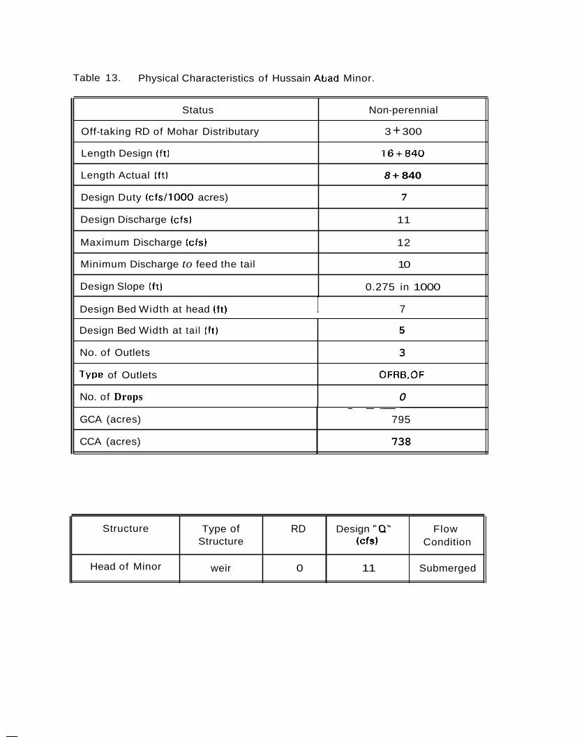
Table 13. Physical Characteristics of Hussain Abad Minor.
Status
Off-taking RD of Mohar Distributary
Length Design ( f t )
Length Actual ( f t )
Design Duty (c fs / l000 acres)
Non-perennial
3 + 300
1 6 + 8 4 0
8 f 840
7
Design Discharge (cfs)
Maximum Discharge (cfsl
Minimum Discharge to feed the tail
Design Slope (ft)
Design Bed Width at head l f t ) I 7
11
12
10
0.275 in 1000
Design Bed Width at tai l I f t )
No. of Outlets
Type of Outlets
No. of Drops
~ ~~
5
3
OFRB,OF
0
GCA (acres)
CCA (acres)
~ ~~~
795
738
Structure
Head of Minor
Type of RD Design "0" Flow Structure (cfs) Condition
weir 0 11 Submerged

6.1.3. 3-L Distributary
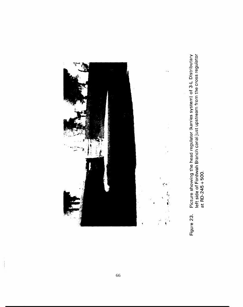
The 3-L Distributary offtakes froin the left side of Fordwah Branch Canal just upstream from the cross regulator located at RD- 2 4 5 + 5 0 0 and runs parallel with the Fordwah Branch Canal from the head uptill RD-21 +OOO. This is a non-perennial distributary having a total design discharge of 18 cusecs, but its old design discharge was 23 cusecs. The head regulator is controlled with karries or tree branches (Figure 2 3 ) and the f low condition is non-modular. This distributary normally runs less than the design discharge. The tail was designed a t RD-27 +OOO, but later the farmers in the tail reach area were able to get a direct outlet from Fordwah Branch Canal. Now, the tail is at RD- 23 + 100. There is no revised discharge rating table for this distributary. The banks are badly damaged by cattle. Also, the bed was damaged at some places by the contractor during rehabilitation work along Fordwah Branch Canal in the beginning of rabi, 1995-96. This distributary is partially in fill/cut from head to tail.
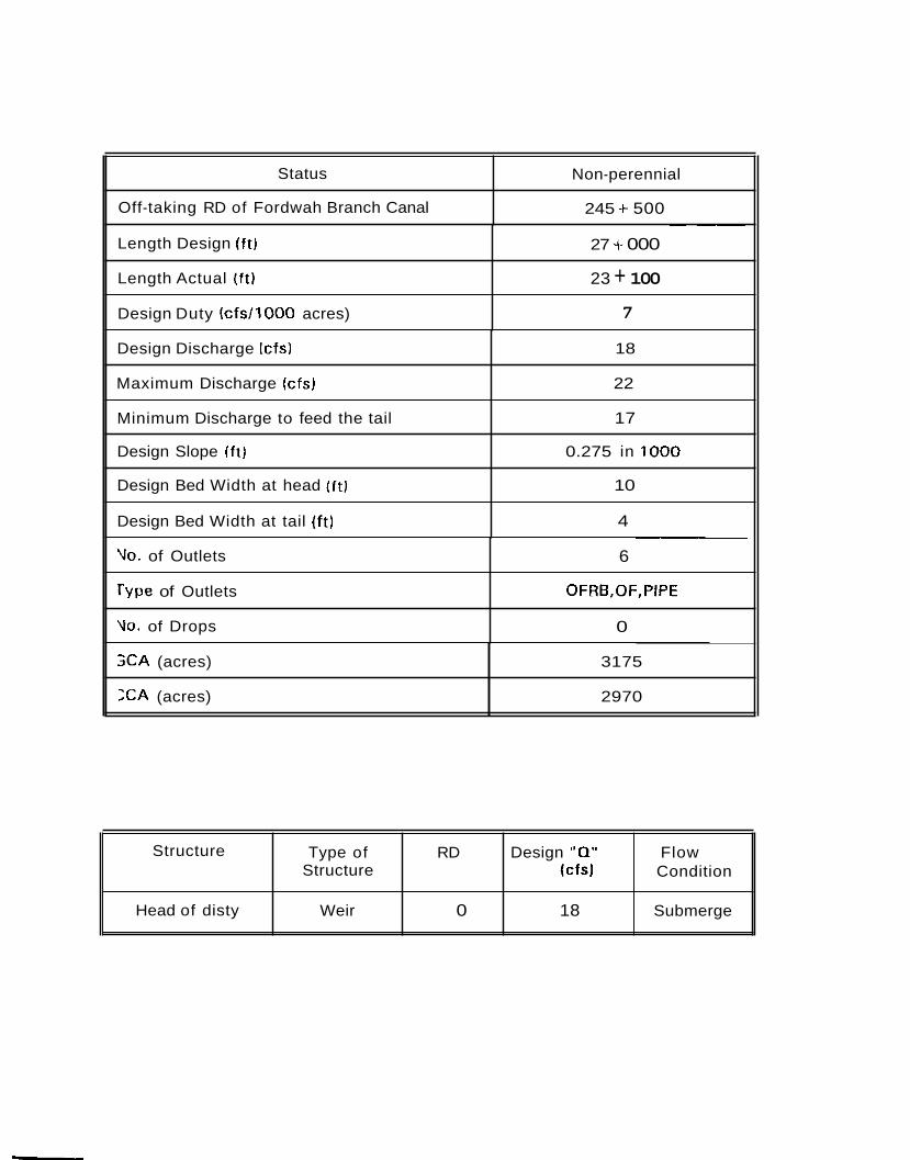
The physicalcharacteristics of 3-L Distributary are given in Table 14. However, other information collected for 3-L Distributary are:
t About 95 % of the people are locals and 5 % are settlers living along 3-L Distributary;
The EC of the ground water was measured as 950 near the head, 400 in the middle and 1700 from the tail reach command area;
*
S.No
1
2
3
Total Land (acres) Reach
200 Head -
150 Middle
25 Tail
65
'1
i
i 3
LL m ._
66
,
Status
Off-taking RD of Fordwah Branch Canal
Non-perennial
245 + 500
Length Design (ft)
Length Actual (f t)
Design Duty (c fs / l000 acres)
~ __ 27 f 000
23 + 100 7
Design Discharge (cfs)
Maximum Discharge (cfs)
Minimum Discharge to feed the tail
Design Slope ( f t l
Design Bed Width at head (ft)
Design Bed Width at tail (ft)
~
18
22
17
0.275 in 1000
10
4
\lo. of Outlets
rype of Outlets
Vo. of Drops
~ ~~
6
OFRB,OF,PlPE
0
X A (acres)
X A (acres)
~ ~~
3175
2970
Structure
Head of disty
Type of RD Design "Q" Flow Structure (cfsl Condition
Weir 0 18 Submerge
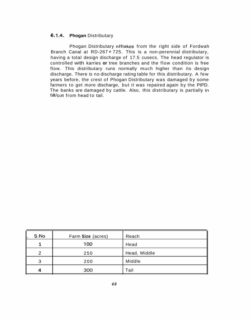
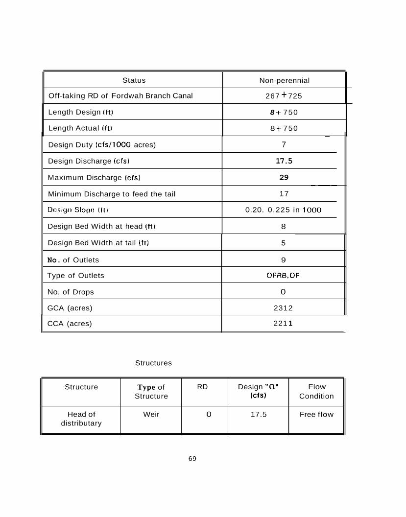
6.1.4. Phogan Distributary
Phogan Distributary olftakes from the right side of Fordwah Branch Canal at RD-267 + 725. This is a non-perennial distributary, having a total design discharge of 17.5 cusecs. The head regulator is controlled with karries or tree branches and the f low condition is free f low. This distributary runs normally much higher than its design discharge. There is no discharge rating table for this distributary. A few years before, the crest o f Phogan Distributary was damaged b y some farmers to get more discharge, but i t was repaired again by the PIPD. The banks are damaged by cattle. Also, this distributary is partially in fill/cut from head to tail.
- S.No Farm Size (acres) Reach
1 100 Head
2 250 Head, Middle
3 200 Middle
4 300 Tail
68
Status
Off-taking RD of Fordwah Branch Canal
Non-perennial
267 + 725
Length Design (ft)
Length Actual ( f t )
8 + 750
8 + 750
~ Design Bed Width at tail ( f t ) 5
' No. of Outlets 9
1 Type of Outlets 0FRB.OF
No. of Drops 0
GCA (acres) 231 2
Design Duty (cfs/l000 acres)
Design Discharge (cfs)
Maximum Discharge (cfs)
Structures
~
7
17.5
29
Minimum Discharge to feed the tail
Dcsigii S~OIJI: ( f t l
Design Bed Width at head ( f t )
69
~ ~~~
17
0.20. 0.225 in 1000
8
CCA (acres) 221 1
Structure
Head of distributary
Type of RD Design "0" Flow Structure (cfsJ Condition
Weir 0 17.5 Free flow
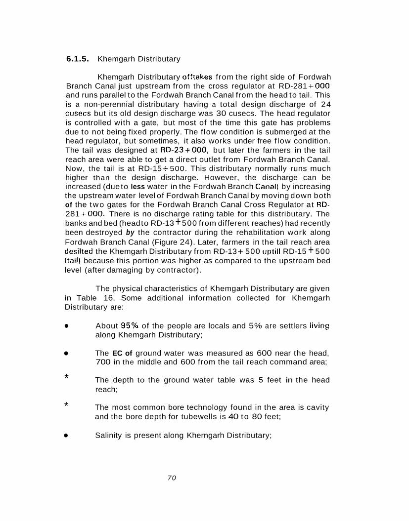
6.1.5. Khemgarh Distributary
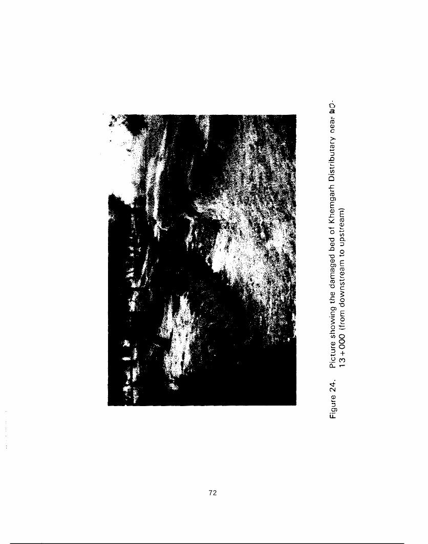
Khemgarh Distributary offtakes from the right side of Fordwah Branch Canal just upstream from the cross regulator at RD-281 +OOO and runs parallel to the Fordwah Branch Canal from the head to tail. This is a non-perennial distributary having a total design discharge of 24 cusecs but its old design discharge was 30 cusecs. The head regulator is controlled with a gate, but most of the time this gate has problems due to not being fixed properly. The flow condition is submerged at the head regulator, but sometimes, it also works under free f low condition. The tail was designed at RD-23+000, but later the farmers in the tail reach area were able to get a direct outlet from Fordwah Branch Canal. Now, the tail is at RD-15 + 500. This distributary normally runs much higher than the design discharge. However, the discharge can be increased (due to less water in the Fordwah Branch CanalJ by increasing the upstream water level of Fordwah Branch Canal by moving down both of the two gates for the Fordwah Branch Canal Cross Regulator at RD- 281 +OOO. There is no discharge rating table for this distributary. The banks and bed (head to RD-13 + 500 from different reaches) had recently been destroyed by the contractor during the rehabilitation work along Fordwah Branch Canal (Figure 24). Later, farmers in the tail reach area desilted the Khemgarh Distributary from RD-13 + 500 uptill RD-15 + 500 (tail) because this portion was higher as compared to the upstream bed level (after damaging by contractor).
The physical characteristics of Khemgarh Distributary are given in Table 16. Some additional information collected for Khemgarh Distributary are:
About 95% of the people are locals and 5% are settlers livirig along Khemgarh Distributary;
The EC of ground water was measured as 600 near the head, 700 in the middle and 600 from the tail reach command area;
* The depth to the ground water table was 5 feet in the head reach;
The most common bore technology found in the area is cavity and the bore depth for tubewells is 40 to 80 feet;
Salinity is present along Kherngarh Distributary;
*
70
S.No
1
2
3
4
Total Land (acres) Reach
100 Head
200 Middle
200 Tail
200 Tail
U a L m m C
72
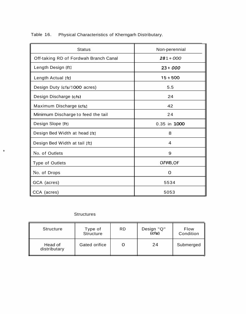
Table 16. Physical Characteristics of Kherngarh Distributary.
Status Non-perennial
Off-taking RD of Fordwah Branch Canal
Length Design (ft)
Length Actual ( f t ) 1 5 + 5 0 0
28 1 + 000
23 + 000
Design Duty (c fs / l000 acres) 5.5
Design Discharge (cfs) 24
Maximum Discharge (cfsl 42
Minimum Discharge to feed the tail 2 4
Design Slope (ft) 0.35 in 1000
Design Bed Width at head ( f t ) 8
4 Design Bed Width at tail ( f t)
No. of Outlets 9
Type of Outlets OFRB,OF
No. of Drops 0
GCA (acres) 5534
CCA (acres) 5053
,
Structure Type of RD Design "Q" Flow Structure (CfS) Condition
Head of Gated orifice 0 24 Submerged distributary -
Structures
6.1.6. 4-L Distributary
The 4-L Distributary offtakes from the left side o f Fordwah Branch Canal just upstream from the cross regulator located at RD- 281 +OOO and runs parallel to the Fordwah Branch Canal f rom the head to tail. This is a non-perennial distributary having a total design discharge o f 14 cusecs but its old design discharge was 16 cusecs. The head regulator is controlled wi th karries or tree branches and the f low condition is non-modular. The tail was designed at RD-19 + 700 but later the farmers in the tail reach area were able to get a direct outlet f rom Fordwah Branch Canal. Now, the tail is a t RD-17 + 350 but the type of tail outlet is 'OFRB' and it cannot draw more discharge even with more supply of water at the tail. Due to this reason, farmers o f the tail reach area had made a permaiient cut near the tail outlet to avoid a breach occurring close t o the tail outlet and also to get all the amount o f water which reaches the tail. This distributary normally runs a litt le bit more than the design discharge. However, the discharge can be increased (due to less water in the Fordwah Branch Canal) b y increasing the upstream water level o f Fordwah Branch Canal (by moving d o w n both o f the t w o gates of Fordwah Branch Canal Cross Regulator at RD-281 +OOO). There is no discharge rating table for 4-L Distributary. The banks and bed (head to RD-13 +OOO f rom different reaches) had recently been destroyed b y the contractor during rehabilitation work along Fordwah Branch Canal. Later, the farmers of the tail reach command area desilted f rom RD- 13 + 500 uptill RD-17 + 350 (tail) because this port ion was higher as compared to the upstream bed level (after damaging by contractor).
The physical characteristics of 4-L Distributary is given in Table 17. Some other information collected for 4-L Distributary are:
About 95% o f the people are locals and 5% are settlers living along 4-L Distributary;
The EC o f the ground water was measured as 500 near the head, 1400 in the middle and 460 in the tail reach command area;
The ground water table is 4 feet below the ground surface at the head reach;
*
The most common bore technology found in the area is cavi ty and the bore depth for tubewells is 40 to 80 feet;
74
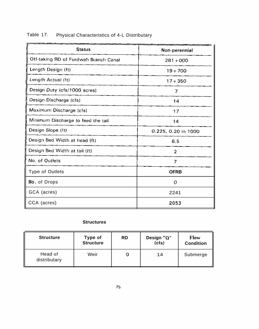
Table 1 7. Physical Characteristics of 4-L Distributary
Type of Outlets
No. of Drops
GCA (acres)
CCA (acres)
OFRB
0
2241
2053
Structures
Structure
Head of distributary
Type of RD Design "0" Flow Structure (cfs) Condition
Weir 0 14 Submerge
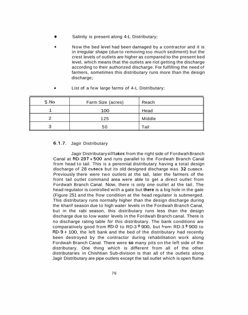
Salinity is present along 4-L Distributary;
S.No
1
2
3
* Now the bed level had been damaged by a contractor and it is in irregular shape (due to removing too much sediment) but the crest levels of outlets are higher as compared to the present bed level, which means that the outlets are riot getting the discharge according to their authorized discharge. For fulfilling the need of farmers, sometimes this distributary runs more than the design discharge;
Farm Size (acres) Reach
100 Head
125 Middle
50 Tail
* List of a few large farms of 4-L Distributary;
6.1.7. Jagir Distributary
Jagir Distributary offtakes from the right side of Fordwah Branch Canal at RD-297+500 and runs parallel to the Fordwah Branch Canal from head to tail. This is a perennial distributary having a total design discharge of 28 cusecs but its old designed discharge was 32 cusecs. Previously there were two outlets at the tail, later the farmers of the front tail outlet command area were able to get a direct outlet from Fordwah Branch Canal. Now, there is only one outlet at the tail. The head regulator is controlled with a gate but there is a big hole in the gate (Figure 251 and the flow condition at the head regulator is submerged. This distributary runs normally higher than the design discharge during the kharif season due to high water levels in the Fordwah Branch Canal, but in the rabi season, this distributary runs less than the design discharge due to low water levels in the Fordwah Branch canal. There is no discharge rating table for this distributary. The bank conditions are comparatively good from RD-0 to RD-3 + 900, but from RD-3 + 900 to RD-9+ 100, the left bank and the bed of the distributary had recently been destroyed by the contractor during rehabilitation work along Fordwah Branch Canal. There were so many pits on the left side of the distributary. One thing which is different from all of the other distributaries in Chishtian Sub-division is that all of the outlets along Jagir Distributary are pipe outlets except the tail outlet which is open flume.
76
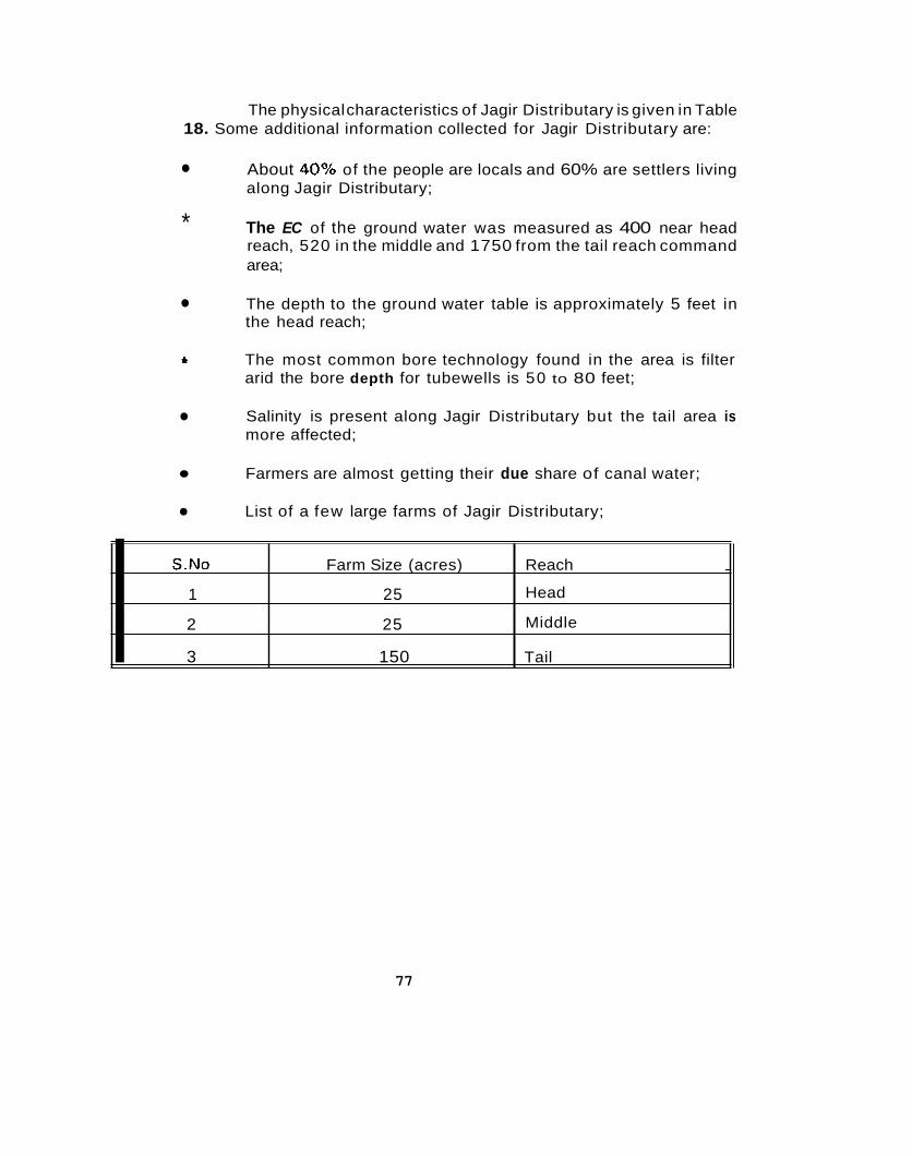
The physical characteristics of Jagir Distributary is given in Table 18. Some additional information collected for Jagir Distributary are:
S.No Farm Size (acres) Reach ~
1 25 Head
2 25 Middle I 3 150 Tail
About 40% of the people are locals and 60% are settlers living along Jagir Distributary;
* The EC of the ground water was measured as 400 near head reach, 520 in the middle and 1750 from the tail reach command area;
The depth to the ground water table is approximately 5 feet in the head reach;
ti The most common bore technology found in the area is filter arid the bore depth for tubewells is 50 to 80 feet;
Salinity is present along Jagir Distributary but the tail area is more affected;
Farmers are almost getting their due share of canal water;
List of a few large farms of Jagir Distributary;
77

78
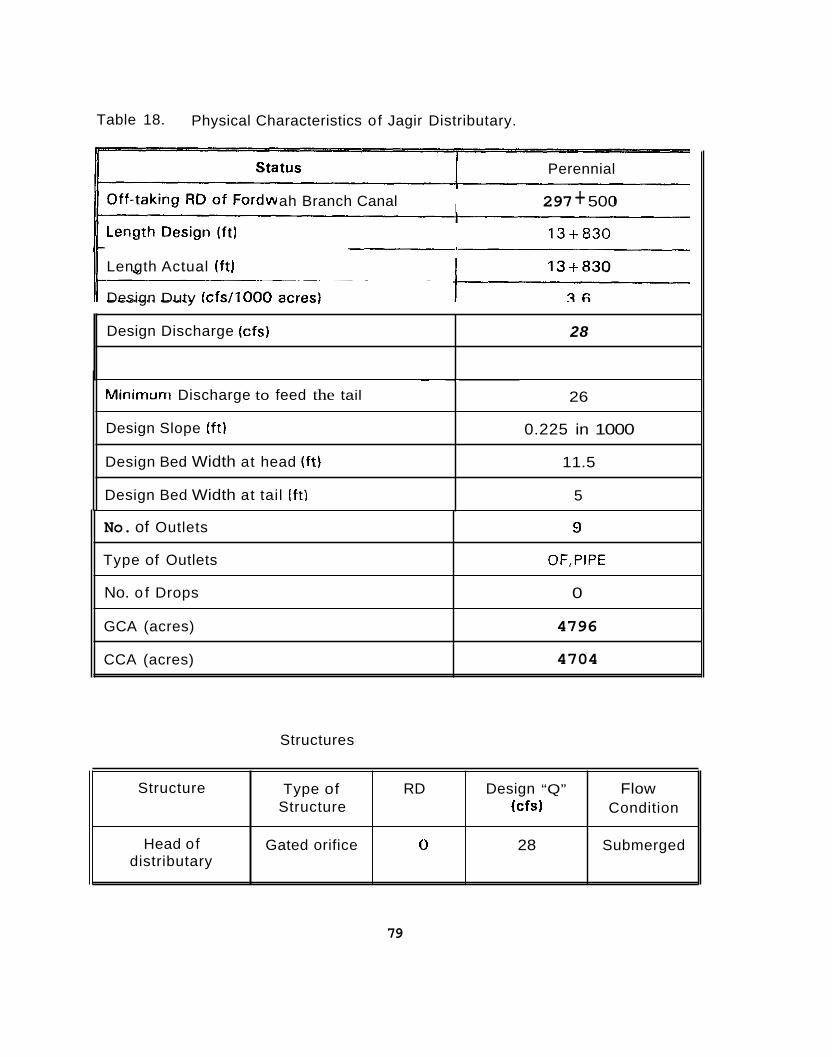
Table 18. Physical Characteristics of Jagir Distributary.
~~
Design Discharge (cfs)
Perennial
297 + 500
13+830
ah Branch Canal
Length Actual ( f t )
Design Duty (c fs / l000 acres1
28
~
Minimum Discharge to feed the tail
Design Slope (ft)
Design Bed Width at head (ft)
Design Bed Width at tail I f t)
- 26
0.225 in 1000
11.5
5
No. of Outlets
Type of Outlets
No. o f Drops
GCA (acres)
CCA (acres)
Structures
9
OF,PIPE
0
4796
4704
Structure
Head of distributary
79
Type of RD Design “Q” Flow Structure (cfs) Condition
Gated orifice 0 28 Submerged

6.1.8. Shahar Farid Distributary
Shahar Farid Distributary offtakes from the right side of Fordwah Branch Canal just upstream from the cross regulator a t RD-316+380. This is a non- perennial distributary having a total design discharge of 153 cusecs. 'The head regulator is controlled with a gate (Figure 26). The f low condition at the head regulator is modular. This distributary normally runs less than the design discharge. However, the discharge can be increased (due t o lcss water i t ) the Fordwah Branch Canal) by increasing the upstream water level o f Fordwah Branch Canal (by moving down all three gates o f Fordwah Branch Canal Cross Regulator at RD-316+ 3801. There are four fall structures; (1 1 a t RD-5 + 500, (2) at RD-46+ 700, (3) at RD-53 + 5 0 0 and (4) a t RD-67 +OOO, but all of these fall structure are submerged due to sediment deposition (although just upstream of the Shahar Farid Head Regulator there is a silt ejector in the Fordwah Branch Canal as shown in Figure 26. There is a Hayerwah Minor, which offtakes a t RD- 46 + 700 on the left side just upstream from the fall structure but there is no discharge rating table for this minor. The discharge rating table (of Shahar Farid Distributary) which is provided to the Gauge Reader is very old and not yet revised although the crest was raised 0.86 feet ( to avoid overtopping from the gate o f Shahar Farid Distributary during excess water in Fordwah Branch Canal) officially in the beginning of 1995. The tail was designed at RD-74+880 but sometimes water hardly reaches at RD-66+ 630. The tail has been dry for 15 years. During the flood (in August, 1988). the tail reach area o f Shahar Farid Distributary was damaged badly and now, the distributary is almost finished just downstream from RD-68+ 100. After the flood, the PlPD made a bund at the right bank (to save the area left side of the distributary] f rom RD-53 + 500 to tails. N o w the right bank of Shahar Farid Distributary is higher 3 to 5 feet as compared t o the left bank just downstream from RD-53+ 5 0 0 to tail. Farmers have made cuts and installed pipes along distributary to use tubewells water frequently due to shortage of canal water in the tail reach area same thing is happening with Hayerwah minor.
The physical characteristics of Shahar Farid Distributary and Hayerwah Minor are listed in Tables 19 and 20, respectively. Some other information collected for Shahar Farid Distributary are:
* About 90% o f the people are locals5 and 10% are settlers' living along Shahar Farid Distributary;
~~ ~
native from the same area which is now in the command area of Fordwali Irrigation System particularly Chishtian Sub-division.
who came from any placeldistrict within pakistan or migrants from India at the time of partition (19471 before or after the partition.
'
80
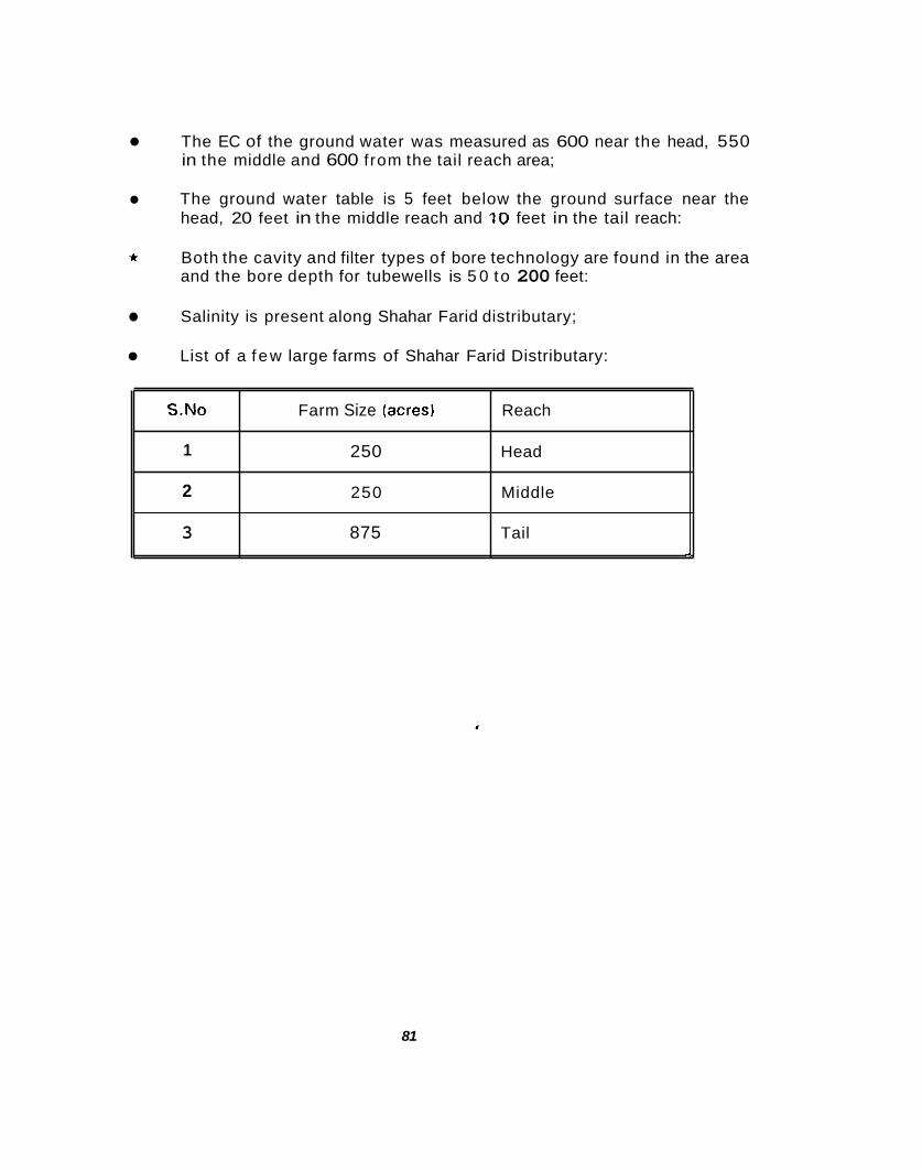
The EC of the ground water was measured as 600 near the head, 550 in the middle and 600 from the tail reach area;
S.No
1
2
3
The ground water table is 5 feet below the ground surface near the head, 20 feet in the middle reach and 10 feet in the tail reach:
Farm Size (acresl Reach
250 Head
250 Middle
875 Tail -
t Both the cavity and filter types of bore technology are found in the area and the bore depth for tubewells is 5 0 to 200 feet:
Salinity is present along Shahar Farid distributary;
List of a f ew large farms of Shahar Farid Distributary:
81

Figure 26. Picture showing the head regulator (gated) of Shahar Farid Distributary and silt ejector at the right side of Fordwah Branch Canal just upstream from the cross regulator a t RD-316+380.
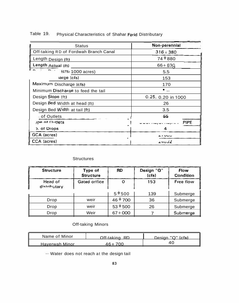
Table 19. Physical Characteristics of Shahar Farid Distributary
Design (ft) Actual ( f t )
ILIW 1000 acres) ,arge Icfs)
m Discharqe (cfs)
;lope ( f t ) k d Width at head (ft)
- e to feed the tail
- 'idth at tail ( f t)
I of Outlets
1 7 1 c I 'Jon
Status Off-taking R D of Fordwah Branch Canal ., I " 7 40"
74 + 880 66 + 63r
5.5 153 170
0.25. 0.20 in 1000 26 3.5 55
_ _
11 Length
Maximu
Minimum Discharat Design : Design E
Design Bed v\i
11 Lenoth
Drop
Drop Drop
5 + 500 139 Submerge 46 + 700 36 Submerge
53 + 500 26 Submerge
weir
weir Weir
U i l
67 + 000 7 Submerge
Structures
Off-taking Minors
I Off-taking RD I Design "Q" (cfs) Name of Minor
Hayerwah Minor 46 + 700 40
-- Water does not reach a t the design tail
83
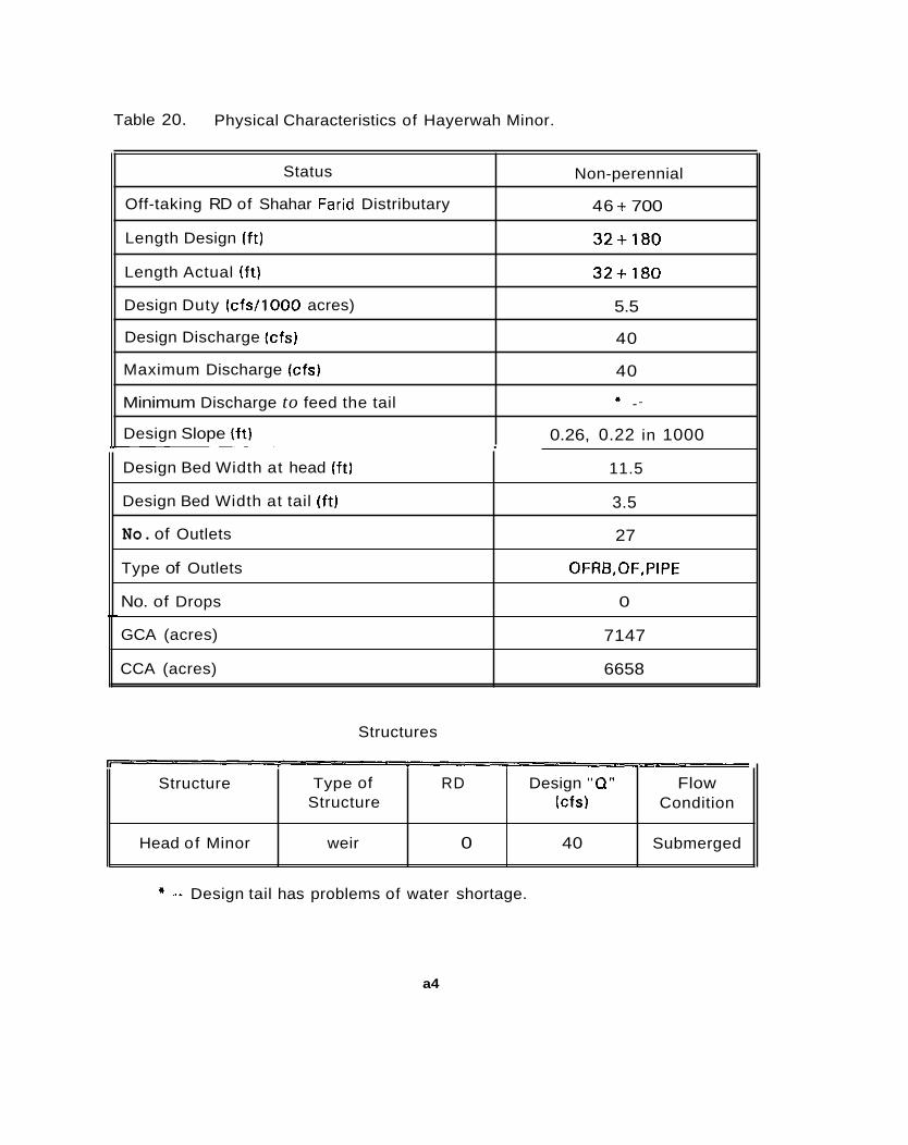
Table 20. Physical Characteristics of Hayerwah Minor.
Status
Off-taking RD of Shahar Farid Distributary
Length Design (ft)
Length Actual (f t)
Design Duty tcfs/1000 acres)
Design Discharge (cfs)
Maximum Discharge (cfs)
Minimum Discharge to feed the tail
Design Slope (ft)
Non-perennial
46 + 700
32+180
32+180
5.5
40
40
* .-
0.26, 0.22 in 1000
Structures
Design Bed Width at head (ft)
Design Bed Width at tail (ft)
No. of Outlets
Type of Outlets
No. of Drops
GCA (acres)
CCA (acres)
11.5
3.5
27
OFRB,OF,PIPE
0
7147
6658
-- Design tail has problems of water shortage.
Structure
Head of Minor
a4
Type of RD Design "0" Flow Structure Icfs) Condition
weir 0 40 Submerged
6.1.9. Masood Distributary
Masood Distributary offtakes from the right side Fordwah Branch Caiial just upstream from the cross regulator at RD-316-1-380. This is a perenriial distributary having a total design discharge of 35 ciisecs. The head regulator is controlled with a gate. The f low condition at the head regulator is non-modular. This distributary normally runs less than its design discharge. However, the discharge can be increased (due to less water in the Fordwah Branch Canal) by increasing the upstream water level of Fordwah Branch Canal (by moving downwards all of three gates of Fordwah Branch Canal Cross Regulator at RD-3lG+3801. The discharge rating table which is provided to the Gauge Reader is very old arid iiot yet revised. The tail was tlesigiied a t HD-52 d 300, b t i t kifw (in 1995-96) the farmers in the tail reach area were able to get t w o direct oritlets from Fordwah Branch Canal. Now, the tail is at RD-45 + 950. There are three fall structures; (1) at RD-18 +OOO which is submerged, (2) the fall structure at RD-24+000 is also subniergcd (but sonietiriies free f low too), and (3) at RD-37+250 is free flow.
The physical characteristics of Masood Distributary are given in Table 21. Some additional information collected for Masood Distributary are:
S.No I 2 3
Farm Size (acres) Reach 175 87 Middle
200 Tail
Head -
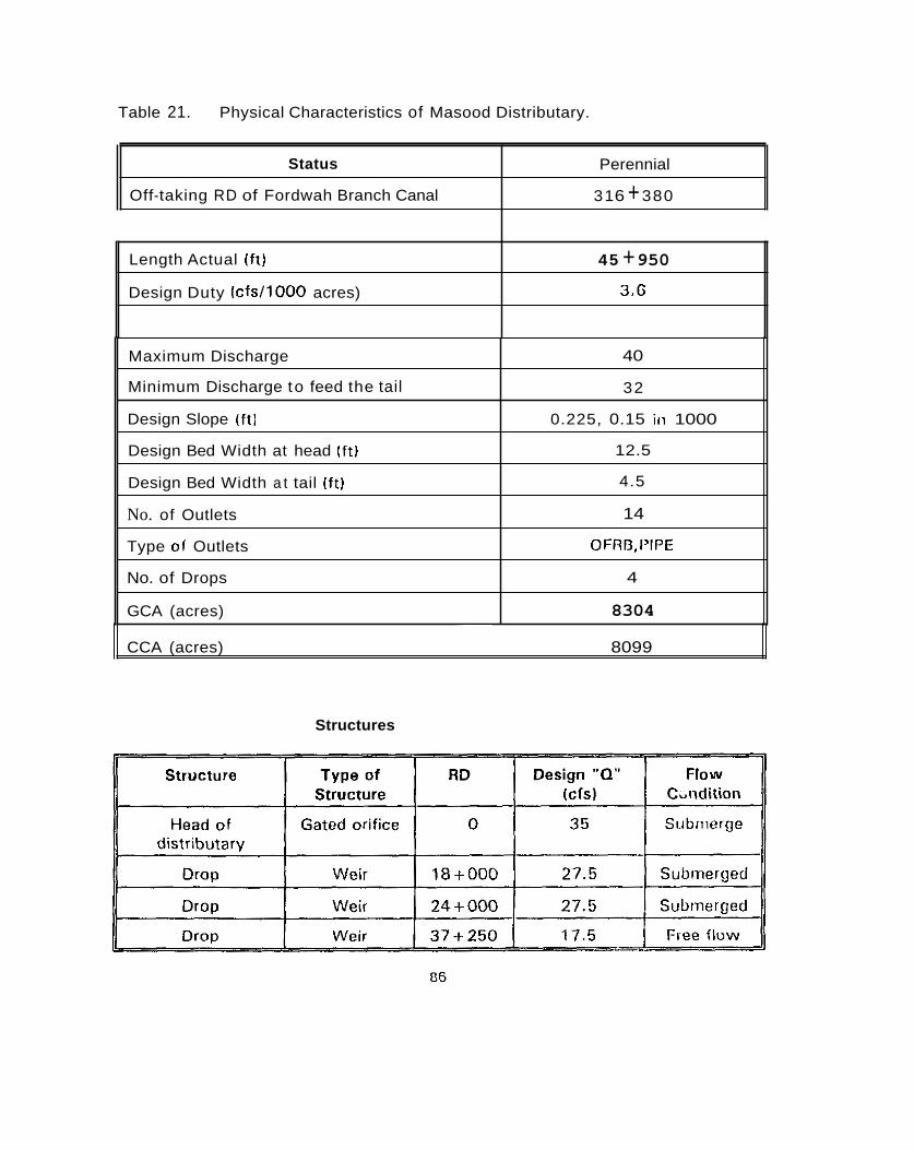
Table 21. Physical Characteristics of Masood Distributary.
Status
Off-taking RD of Fordwah Branch Canal
Perennial
31 6 + 380
Length Actual (f t)
Design Duty (c fs / l000 acres)
45 + 950 3.6
Maximum Discharge
Minimum Discharge to feed the tail
Design Slope ( f t l
Design Bed Width at head (ft)
Design Bed Width a t tail ( f t)
No. of Outlets
Type of Outlets
No. of Drops
GCA (acres) ~-
CCA (acres) 8099
40
32
0.225, 0.15 in 1000
12.5
4.5
14
OFRI3,IVPE
4
8304
Structures
Note:
The farmers of the tail reach area (of Masood Distributary) were not receiving canal water according to their need. So, they all claimed t o the higher officials of PlPD (in 1987-88). Then to solve this real problem, PlPD agreed to make a minor of a total design discharge of 9 cusecs and farmers of the tail reach promised to help the PlPD in this regard. Then, the Sub-engineer of PlPD made a longitudinal section (with all details together w i th estimated amount in rupees for spending) of that minor under the supervision of the SDO Chishtian. It was decided that this new minor wil l off take to the right side of Fordwah Branch Canal just upstrean) f rom the cross regulator located at RD-353 + 500.
Then, the PlPD (after completing all paper work) decided to postpono it, due to nor1 availability of funds for this purpose. The farmers near RD-36+000 of Masood Distributary did not like it. They also used all o f their resources against it. They were saying that, when the n e w tail of Masood Distributary will be near RD-36+000, then they wi l l get less water due to the n e w design discharge 26 cusecs at the head regulator of Masood Distributary. Then, due to pressure f rom both sides of farmers, in 1995-96, the PIPD installed two direct outlets near RD- 3 6 7 + 0 0 0 and 368i-000 on the right side of Fordwah Branch Canal to fulfill the needs of the farmers in the tail reach area. The program for making a new minor was therefore cancelled. Now, the n e w tail o f Masood Distributary is a t RD-45 + 950 and just downstream from this outlet the Masood Distributary is officially closed, but the type o f the n e w tail outlet is still OFRB not open flume. This distributary was also desilted ( f rom RD-37 + 250 to RD-45 + 950) b y PlPD during the closure period of January, 1996.
87
6.1.10. Soda Distributary
Soda Distributary offtakes from the right side o f Fordwah Branch Canal a t RD-334+000. This is a non-perennialdistributary 'having a total design discharge o f 77 cusecs. The head regulator is controlled wi th karries and the f low condition is free f low. This distributary normally runs as per the design discharge. There is no discharge rating table for this distributary. There is a fall structure at RD-3 +OOO which is submerged. The fall structure at RD-9 + 500 is also submerged, bu t the fall structure at RD-38+200 is free f low. The bank conditions were comparatively good f rom head to tail because o f some maintenance work (bank strengthening, berm cutting, silt clearance in different reaches) done in the beginning of 1995. Later, about 200 feet just downstream f rom the head regulator and 400 feet near RD-41 +OOO was also lined due to a weakness of the banks.
S.No
1
2
The physical characteristics of Soda Distributary are given in Table 22. Some additional information collected for Soda Distributary are:
Farm Size (acres) Reach
250 Head
125 Middle
+ About 95% o f the people are locals and 5 % are settlers living along Soda Distributary;
The EC o f the ground water was measured as 500 in the head reach, 6 5 0 in the middle and 850 from the tail reach area;
+
+ The ground water table is about 10 t o 15 feet be low the ground surface;
* The most common bore technology found in the area is cavity and the bore depth for tubewells is 50 to 180 feet;

Table 22. Physical Characteristics of Soda Distributary.
Status
Off-taking RD of Fordwah Branch Canal
Length Design ( f t )
Length Actual ( f t )
Design Duty Icfs/ lOO0 acres1
Design Discharge(cfs)
Maximum Discharge (cfs)
Minimum Discharge to feed the tail
Non-perennial
334- + 000
43 + 700
43 + 700
5.5
77
80
75
Design Slope ( f t )
Design Bed Width at tail ( f t )
No. of Outlets
~ ~ ~~
I 0.30, 0.28 in 1000
3.5
33
Design Bed Width at head (ft l I 18
GCA (acres) 10622
Type of Outlets I OFRB,OF
CCA (acres)
No. of Droas I 3
10113
r
Structure Type of RD Design "0" Flow S ti uctur e lcfs) Condition
Head of weir 0 77 Free flow distributary
. Drop Weir 3 t 000 67 Submerged
Drop Weir 9 + 500 58 Submerged
Drop Weir 38 + 200 7 Free Flow __
89

6.1.11. 5 - L Distributary
The 5-L Distributary offtakes from the left side of Fordwah Branch Canal at RD-348+800 but about 1.5 kilometers upstream from the cross regulator located at RD-353+500. This is a perennial distributary having a total design discharge of 4 cusecs. The head regulator is controlled with karries or tree branches but the flow condition at the head regulator is non-modular. This distributary is getting 1 lo 2 feet of sediment every year, although just close to the head regulator, there is a silt ejector in the Fordwah Branch Canal as shown in Figure 27. This distributary normally runs as per the design discharge. The discharge of 5-L Distributary depends upon the water level in the Fordwah Branch Canal, but the discharge can be increased by moving downwards the gate at RD-353+500 of Fordwah Branch Canal. There is no discharge rating table for this small distributary. There is one fall structure at RD-4+900 which is submerged. Most of the breaches were occurring from RD-1 +OOO to 3 +OOO on the left side due to weakness of the banks. During the closure period o f January 1996, this distributary was desilted (from 1 to 2.5 feet head to tail l by all of the farmers of 5-L Distributary. In the past, there were two outlets at the tail, one was a front tail and the second a right tail. But the command area of the front tail outlet was occupied by houses and n o w the discharge o f this outlet is going into the right tail outlet. This outlet was not talten out by the PIPD.
S.No Farm Size (acres) Reach 1 33 Head 2 28 Middle 3 53 Tail -
90
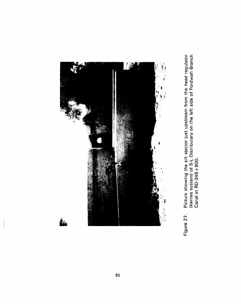
91
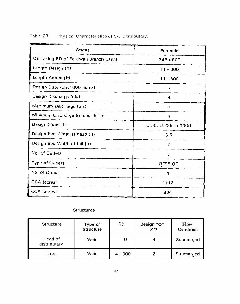
Table 23. Physical Characteristics of 5-L Distributary.
Structure
Head of distributary
Drop
Structures
Type of RD Design "Q" Flow Structure Icfs) Condition
Weir 0 4 Submerged
4 4- 900 2 Su bnier g ed Weir
92
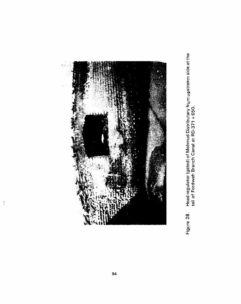
6.1.12. Mehmud Distributary
Mehmud Distributary offtakes from the front side at the tail of Fordwah Branch Canal at RD-371 +650 (Figure 28 ) . This is a perennial distributary having a total design discharge of 8.25 cusecs. The head regulator is controlled with a gate. The flow condition at the head regulator is submerged. This distributary normally runs more than the design discharge. There is no revised discharge table for this tJi..,ributary. During the closure periods each year, farmers of this distributary try their best to desilt it by themselves. Therefore, the actual bed of this distributary was lower than the design bed level.
The physical characteristics of Mehmud Distributary are given in Table 24. Some other information collected for Mehmud Distributary are:
S.No
1
2
3
4
* About 10% of the people are locals a i d 90% are settler living along Mehmud Distributary;
The EC of the ground water was measured as 820 in the head reach, 860 in the middle and 700 from the tail reach area;
The ground water table is about 10 to 15 feet below the ground surface;
Total Land (acres) Reach
62 Head
50
87 Middle
50
* The most common bore technology found in the area is filter and the bore depth for tubewells is 50 to 100 feet;
93
E 2 m c (0 a 3
E 0
w N m L
94
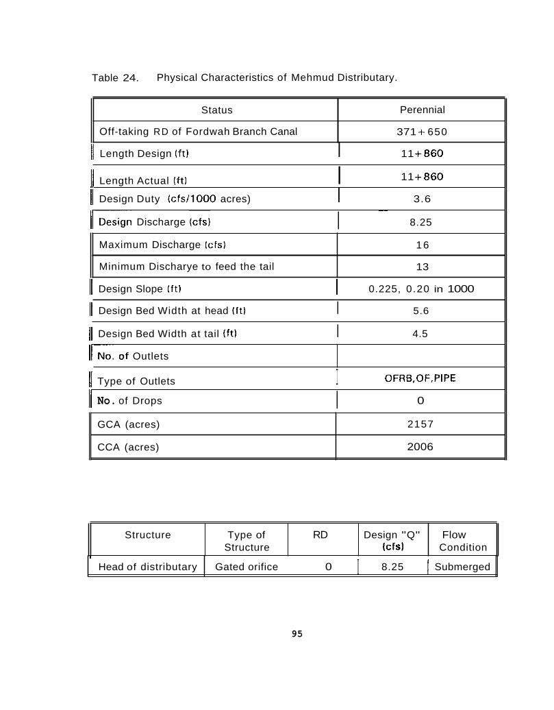
Table 24. Physical Characteristics of Mehmud Distributary.
Status
Off-taking RD of Fordwah Branch Canal
Perennial
371 + 650
11 Length Design ( f t ) I 11 +860
Maximum Discharge (cfs)
Minimum Discharye to feed the tail
11 +860 I] Length Actual ( f t l I
16
13
11 Design Duty (cfs/1000 acres) I 3.6
GCA (acres)
CCA (acres)
)IDesign Discharge (cfs)
2157
2006
I ~~
8.25
Structure Type of RD Design "Q" Flow Structure (cfs) Condition
r Head of distributary
11 Design Slope I f t ) I 0.225, 0.20 in 1000
Gated orifice 0 8.25 I Submerged I
11 Design Bed Width at head ( f t l I 5.6
11 Design Bed Width at tail ( f t ) I 4.5
I I i o . of Outlets
OFRB,OF,PIPE 11 Type of Outlets I 11 No. of Drops 0 I
95
I i

6.1.13. Fordwah Distributary
Fordwah Distributary offtakes from the left side a t the tail of Fordwah Branch Canal at RD-371 -t 650. This is a perennial distributary having a total design discharge of 1 5 8 cusecs. The head regulator has t w o gates.The f low condition at the head regulator is submerged. This distributary normally runs as per its design discharge. There is no revised discharge table for this distributary. There is a minor (J iwan Minor) which offtakes from the right side of Fordwah Distributary just upstream from the fall structure at RD-64+050. There is a fall structure at RD- 1 5 + 040, which is free f low. The fa!l structures at RD-33 +300, RD- 42+800 and RD-64+050 arc submerged. From R D - l 2 4 + 0 0 0 t o RD- 139 + 780 (tail), berm cutting and silt clearaiice work was doiie by a contractor under the supervision of a Sub-engineer and mate of PlPD during the closure period of January, '1996. In 1988-92, 29500 plants were sown on both sides of Fordwa Distributary for safety factor.
The physical characteristics of Fordwah Distributary are given in Table 25, while similar data for J iwan Minor is listed in Table 26. Some other information collected for Fordwah Distributary are:
About 20% of the people are locals and 8 0 % are settlers living along Fordwah Distributary;
The EC of ground water was measured a s 800 in the head reach, 900 in the middle and 1250 from the tail reach area;
*
The ground water table is about 6 feet below the ground surface near the head reach;
1
2
* The most common bore technology found in the area is filter and the bore depth for tubewells is 5 0 to 200 feet;
Salinity is present along Fordwah Distributary;
List o f a f ew large farms of Fordwali Distributary;
* *
S.No Farm Size (acres) I Reach
1 5 0 Head
8 5 Middle
3 1 5 0 Tail
96
I I
6.1.14. Azim Distributary
Azim Distributary offtakes from the right side a t the tail of Fordwah Branch Canal a t RD-371 +650. This is a non-perennial distributary having a total design discharge of 244 cusecs. There are two gates at the head regulator. The flow condition at the head regulator is modular. This distributary normally runs less than the design discharge. There is no revised discharge rating table for this distributary. There are three minors, Rathi Minor offtakes at RD-24+800 left side but the crest of this minor was broken, Feroze Minor offtakes at RD-44+ 238 left side and Forest Minor which offtakes at RD-91 +900 right side. There are seven fall structures along Azim Distributary; (1) fall structure a t RD- 11 +950, (2) fall structure at RD-44-1500. (3) fall structure at RD- 52+465, (4) fall structure a t RD-84+385, (5) fall structure a t RD- 91 + 900, (6) fall structure at RD-98 + 950 and (7) fall structure a t RD- 11 3 + 925, but all of the fall structures are totally submerged. The tail was designed at RD-124+660. Now, the new design tail is at RD- 1 18 + 980, but still water does not teach at the tail due to installation of illegal pipes (Figure 291, tampering of the outlets (Figure 30). making illegal cuts and water blocking in the upstream reaches of Azim Distributary.
In the past, an escape (Bahawal Ford Feeder) was in working condition and it was being used for emergency cases to close the breaches, or passing the large water level fluctuations at the tail of Fordwah Branch Canal. But now, this escape (Figure 31 1 has not been used for 15 years and Azirn Distributary is being used as an escape during an emergency. Therefore, Azirn Distributary receives most of the breaches near RD-15 + 000 on the left side.
The physical characteristics of Azim Distributary are given in Table 27, while similar data for Rathi Minor, Feroze Minor and Forest Minor are listed in Tables 28, 29 and 30, respectively. Some additional information collected for Azim Distributary are:
About 85% of the people are locals and 15% are settlers living along Azim Distributary;
The EC of ground water was measured as 700 in the head reach.950 in the middle and 1200 from the tail reach area.
The ground water table is about 15 feet below the ground surface near head reach area;
99 I
! I
1 1

Status
11 Off-takinq RD of Fordwah Branch Canal I 371 + 650 II Perennial
11 Lennth Desinn ( f t ) I 139 + 780 II
large (cfs)
Length Actual (f t) I 139 f 780 Design Duty (c fs / l000 acres) 3.6
158 Design Disch
Maximum Di: scharge (cfs) 190
I Minimum Discharge to feed the tail Desian Slnne ( f t l n 7 s n 175 in innn
160
-
No. of Outlets
Type of Outlets
at tail ( f t ) 5 88
OCOFRB,OCAPM,OFRB,APM, 0F.PIPE
Name of Minor
Jiwan Minor
11 No. of Droos I 4 II
Oft-taking RD Design "(1" (c fs )
64 + 050 27
II GCA (acres) I 42680
i
I
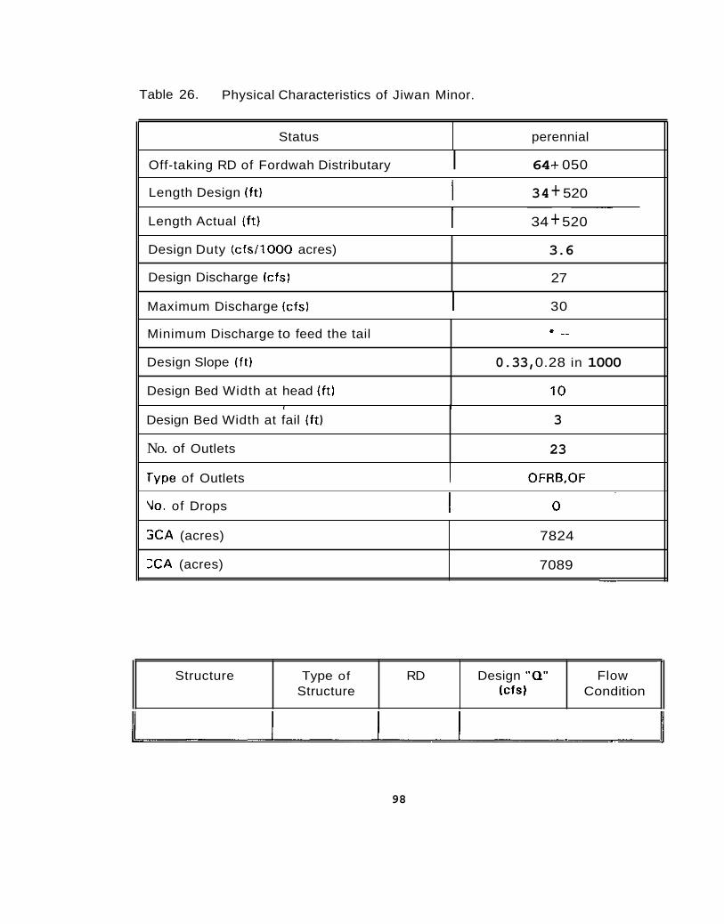
Table 26. Physical Characteristics of Jiwan Minor.
Status perennial
Off-taking RD of Fordwah Distributary I 64 + 050
Design Duty (c fs l l000 acres)
Design Discharge (cfs)
34 + 520 I Length Design (ft)
3.6
27
Length Actual (f t)
Minimum Discharge to feed the tail
Design Slope (ft)
Design Bed Width at head (ft)
~~
34 + 520
+ ..
0.33, 0.28 in 1000
10
Design Bed Width at fail ( f t)
No. of Outlets
Maximum Discharge (cfs) I 30
3
23
SCA (acres)
X A (acres)
7824
7089
Type of Outlets I OFRB,OF
- Structure Type of RD Design "Q" Flow
Structure (cfs) Condition
Vo. of Drops
98

S.No Farm Size (acres)
1 300
2 750
3 750
4 750
5 85
6 100
100
Reach
Head
Head
Middle
Middle
Tail
Tail

101
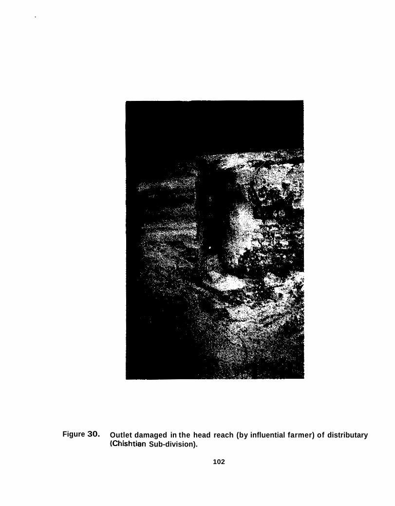
Figure 30. Outlet damaged in the head reach (by influential farmer) of distributary (Chishtian Sub-division).
102

+-c m .-

Table 27. Physical Characteristics of Aziin Distributary.
Status Off-taking RD of Fordwah Branch canal
Length Actual ( f t )
Design Discharge (cfs) Maximum Discharge (cfs) Minimum Discharge to feed the tail
Design Slope(ft) Design Bed Width a t head ( f t ) Design Bed Width at tail ( f t ) No. of Outlets
Length Design (ft)
Design Duty (cfs/l000 acres)
-
-~
- Noii-perennial 371 + 650 124 -I- 660 118+980
5.5 24.4 365
Tail gets always ~iroblern of water shortage
0.20. 0.19 in 1000 34 5.7 75
-
-
Type of Outlets
GCA (acres). CCA [acres) No. of Drops
Structures
- Structure Type of design "0" [
OCOFRB,OCAPM,OFRB,APM 7
3 1 S O T 30459
Structure Condition Free flow
Weir 11 -1-950 Suhmnrnetl
~
i _..I...1. ,, I--- It- Drop Weir 64 Submeraed
I 60 / Submerged 11 Weir z;t;;; 1 Drop Droo Weir 41 Siihrnnrond
Off-taking Minors
I -
Name of Minor Otf-tnkinn RD Dcsinn "n" lc fs l II 11 p a t h i Minor I 28 i- 400 10

Status
Off-taking RD of Azirn Distributary
(1 Length Design ( f t ) I 8 + 000
=
Non-perennial
44 + 238
Length Actual I f t)
Design Duty (c fs / l000 acres)
Design Discharge (cfs)
~ ~
8 -t 000
5 .5
9
11 Design Bed Width a t head (ft) I 6
Maximum Discharge (cfs)
Minimum Discharge to feed the tail
Design Slope Ift)
9
8
0.25 in 1000
Design Bed Width a t tail ( f t )
No. of Outlets
11 GCA (acres) I 1279
~ ~~
6
4
Type of Outlets
No. of Drops
OFRB,OF
0
CCA (acres) - ~~
1226
Structure Type of RD Desiyii "0" Flow Structure Icfs) Condition
Head of Minor weir 0 9 Submerged 2
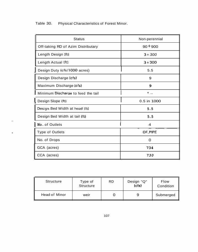
Table 30. Physical Characteristics of Forest Minor.
- Status Non-perennial
Off-taking RD of Azim Distributary 90 + 900
Length Design ( f t )
Length Actual (ft l
3 + 300
3 + 300 11 Design Duty (c fs / l000 acres) I 5.5
Design Discharge (cfs)
Maximum Discharge (cfs)
9
9
*' _ _ 11 Minimum Dischawe to feed the tail I
Design Bed Width at head ( f t )
Design Bed Width at tail ( f t)
(1 Design Slope ( f t ) I 0.5 in 1000
5.5
5.5
Type of Outlets
No. of Drops
11 No. of Outlets I 4 ~~ ~~ ~~~
OF,PlPE
0
GCA (acres)
CCA (acres)
734
730
Structure
Head of Minor
107
Type of RD Design "Q" Flow Structure (cfs) Condition
weir 0 9 Submerged
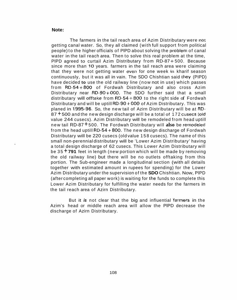
Note:
The farmers in the tail reach area of Azim Distributary were not gett ing canal water. So, they all claimed (w i th full support f rom political people) t o the higher officials o f PlPD about solving the problem o f canal water in the tail reach area. Then to solve this real problem at the time, PlPD agreed to curtail Azim Distributary f rom RD-87 -k 500. Because since more than 10 years. farmers in the tail reach area were claiming that they were not getting water even for one week in kharif season continuously, but i t was all in vain. The SDO Chishtian said they (PIPD) have decided to use the old railway line ( n o w not in use) which passes f rom RD-54+800 o f Fordwah Distributary and also cross Azim Distributary near RD-90+000. The SDO further said that a small distributary will offtake from RD-54+800 to the r ight side of Fordwah Distributary and wil l be uptill RD-90+000 of Azim Distributary. This was planed in 1995-96. So, the new tail of Azirn Distributary wil l be at RD- 87 + 500 and the new design discharge wi l l be a total of 1 7 2 cusecs (old value 244 cusecs). Azim Distributary will be remodeled f rom head uptill n e w tail RD-87 + 500. The Fordwah Distributary wil l also be remodeled f rom the head uptill R D - 5 4 f 8 0 0 . The new design discharge of Fordwah Distributary will be 220 cusecs (old value 1 5 8 cusecs). The name of this small non-perennial distributary will be ’Lower Azim Distributary’ having a total design discharge of 62 cusecs. This Lower Azim Distributary wil l be 3 5 + 791 feet in length (new portion which wi l l be made b y removing the old railway line) but there will be no outlets offtaking from this portion. The Sub-engineer made a longitudinal section (with all details together with estimated amount in rupees for spending) for the Lower Azim Distributary under the supervision o f the SDO Chishtian. Now, PlPD (after completing all paper work) is waiting for the funds to complete this Lower Azim Distributary for fulfilling the water needs for the farmers in the tail reach area of Azirn Distributary.
But it is not clear that the big and influential farmers in the Azim’s head or middle reach area wil l al low the PlPD decrease the discharge of Azirn Distributary.
108
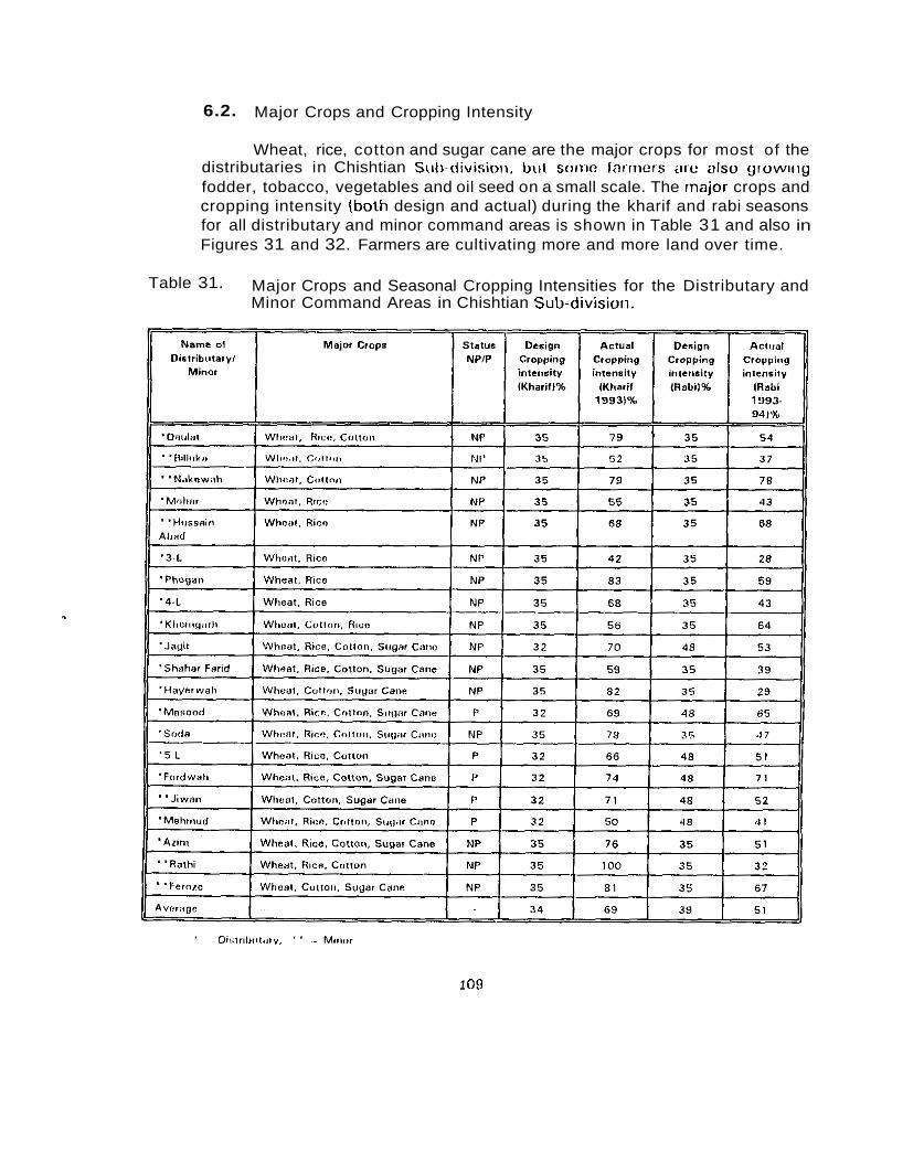
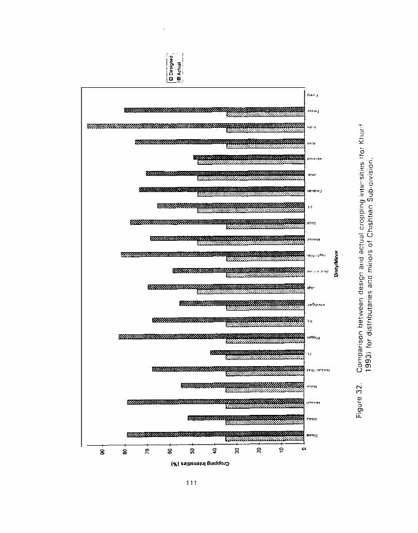
6.2. Major Crops and Cropping Intensity
Wheat, rice, cotton and sugar cane are the major crops for most of the distributaries in Chishtian Stili-division, bur s w i w farriiers are also growlllg fodder, tobacco, vegetables and oil seed on a small scale. The major crops and cropping intensity (both design and actual) during the kharif and rabi seasons for all distributary and minor command areas is shown in Table 31 and also in Figures 31 and 32. Farmers are cultivating more and more land over time.
Table 31. Major Crops and Seasonal Cropping Intensities for the Distributary and Minor Command Areas in Chishtian Sub-division.
1 OD
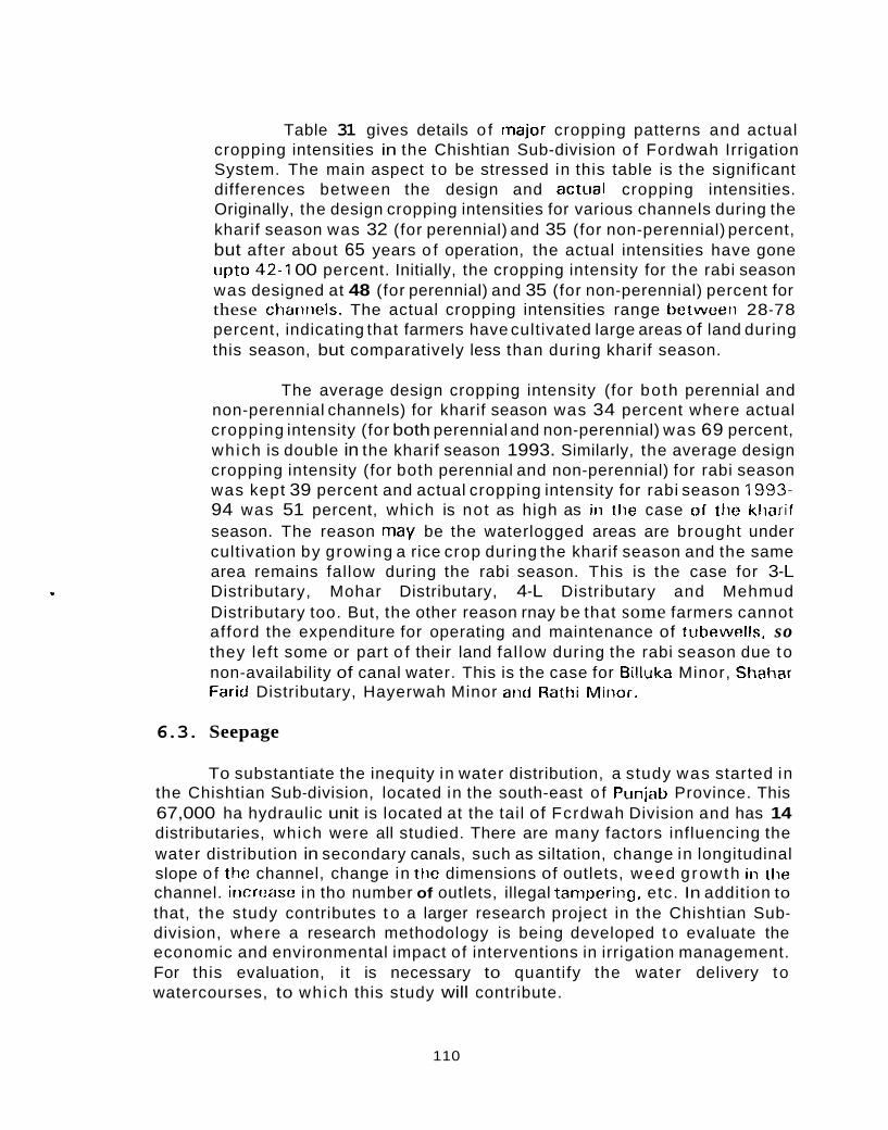
Table 31 gives details o f major cropping patterns and actual cropping intensities in the Chishtian Sub-division o f Fordwah Irrigation System. The main aspect to be stressed in this table is the significant differences between the design and actual cropping intensities. Originally, the design cropping intensities for various channels during the kharif season was 32 (for perennial) and 35 (for non-perennial) percent, but after about 65 years o f operation, the actual intensities have gone upto 42-1 00 percent. Initially, the cropping intensity for the rabi season was designed at 48 (for perennial) and 35 (for non-perennial) percent for these chaririels. The actual cropping intensities range betweeri 28-78 percent, indicating that farmers have cultivated large areas of land during this season, but comparatively less than during kharif season.
The average design cropping intensity (for both perennial and non-perennial channels) for kharif season was 34 percent where actual cropping intensity (for both perennial and non-perennial) was 69 percent, which is double in the kharif season 1993. Similarly, the average design cropping intensity (for both perennial and non-perennial) for rabi season was kept 39 percent and actual cropping intensity for rabi season 1993- 94 was 51 percent, which is not as high as iii the case of t l ic kliarif season. The reason rnay be the waterlogged areas are brought under cultivation by growing a rice crop during the kharif season and the same area remains fallow during the rabi season. This is the case for 3-L Distributary, Mohar Distributary, 4-L Distributary and Mehmud Distributary too. But, the other reason rnay be that some farmers cannot afford the expenditure for operating and maintenance of tubewells. so they left some or part o f their land fal low during the rabi season due to non-availability of canal water. This is the case for Eilluka Minor, Shahar Farid Distributary, Hayerwah Minor and Rathi Minor.
6.3. Seepage
To substantiate the inequity in water distribution, a study was started in the Chishtian Sub-division, located in the south-east o f Punjab Province. This 67,000 ha hydraulic unit is located at the tail of Fcrdwah Division and has 14 distributaries, which were all studied. There are many factors influencing the water distribution in secondary canals, such as siltation, change in longitudinal slope o f the channel, change in the dimensions of outlets, weed growth iii the channel. incrcase in tho number of outlets, illegal tanipering, etc. In addition to that, the study contributes t o a larger research project in the Chishtian Sub- division, where a research methodology is being developed t o evaluate the economic and environmental impact of interventions in irrigation management. For this evaluation, i t is necessary to quantify the water delivery to watercourses, to which this study will contribute.
110

The research question that is being asked: what is the present water distribution in distributaries and h o w does i t compare with official and actual operation targets ?
The objectives o f the study are;
To review the overall water distribution in the 14 distributaries o f the Chishtian Sub-division;
To examine the physical conditions o f the distributaries that are likely to affect the water distribution;
To calibrate and evaluate the hydraulic performaiice of outlet structures in the Chishtian Sub-division; and
to determine the seepage losses for all distributaries.
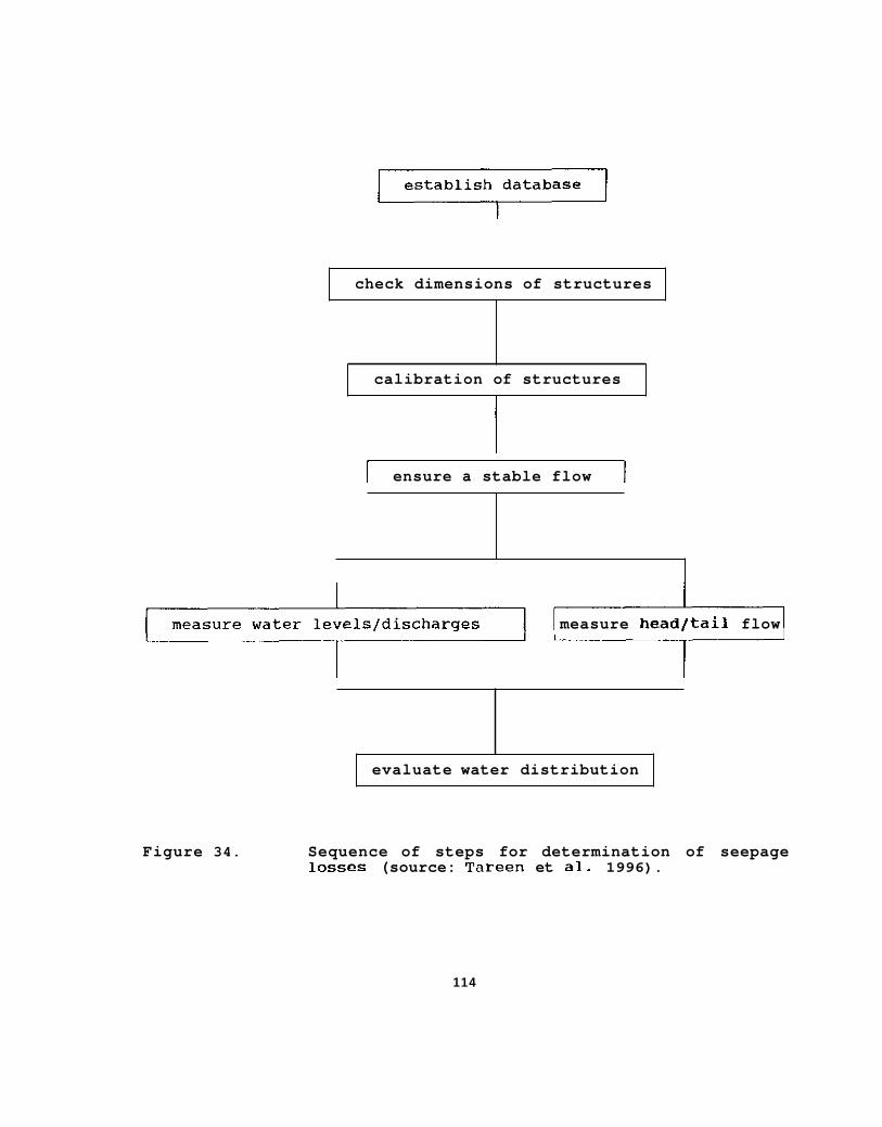
In order t o measure the water distribution in distributaries, deliveries to all watercourses in a distributary were measured, The easiest way to do this is to eiisiire a stable supply to a distributary and measure the dischargo to all water courses within a specific amount of time. This t ime period is dependent on the time that is required for water to f low from the head t o the tail of a distributary (as a function o f hydraulic characteristics such as slope, roughness coefficient, discharge, etc.). In case o f large distributaries, outlets were calibrated prior to the experiment, so that on the day of the experiment, only water levels had t o be measured. The distributary is divided into reaches and the inf low-outf low is measured for each reach during the experiment. This serves as a cross-check for the measured outlet discharges. Also, seepage losses can then be determined reach-wise. The sequence of the different steps which were taken are given in Figure 34.
The inf low-outf low experiments provided good measurements regarding seepage rates in the distributaries of the Chishtian Sub-division. The results are srimmarized in Table 32. However, the seepage for those distributaries running closely parallel t o the Fordwah Branch Canal (Mohar, 3-L. 4-L, Kherngarh, Jagir, and Masood) is much lower than for the other distributaries. Only in tl ie case of Kherngarh, whose banks had recently been destroyed by contractors was a much higher loss rate found to exist. (For more details, see Water Distribution in Chishtian Sub-division by Tareen et al, IIMI, 1996.)
113
i
I I
establish database G I
check dimensions of structures
calibration of structures I
I ensure a stable flow 1
measure headltail flow
Figure 34.
I
evaluate water distribution
Sequence of steps for determination of seepage losses (source: Tareen et al. 1996).
114
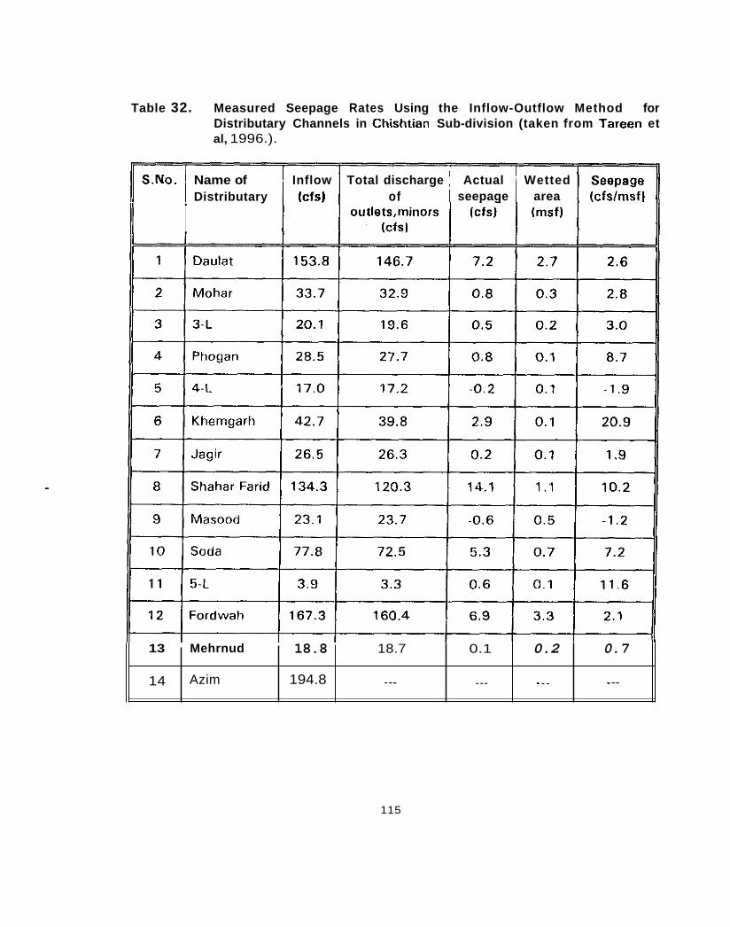
Table 32. Measured Seepage Rates Using the Inflow-Outflow Method for Distributary Channels in Chishtian Sub-division (taken from Tareen et al, 1996.).
Inflow Total discharge Actual Wetted seepage area
S.No. Name of Distributary (cfs) of
14
It I
Azim 194.8 ..- ... -.. _--
13 Mehrnud
115
18.8 18.7 0.1 0.2 0.7

6.4. Sediment for all Distributaries in Chishtian Sub-division
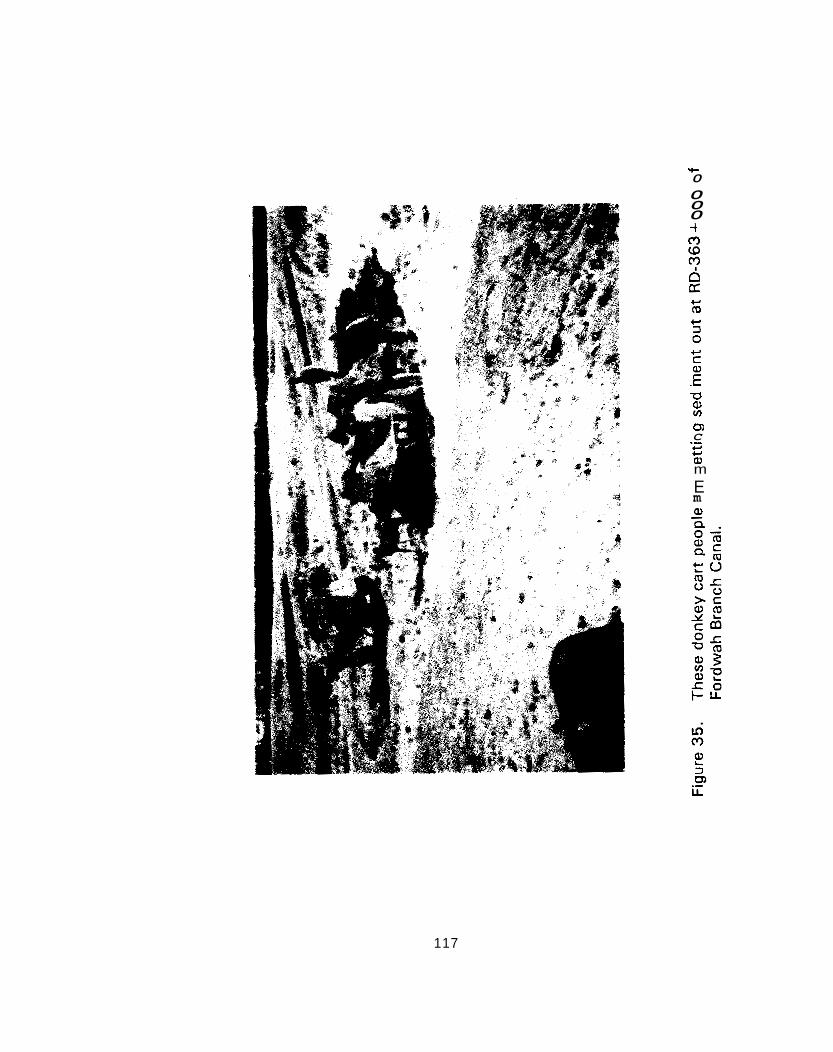
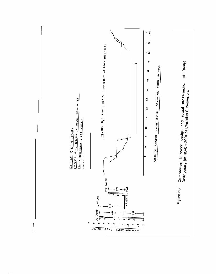
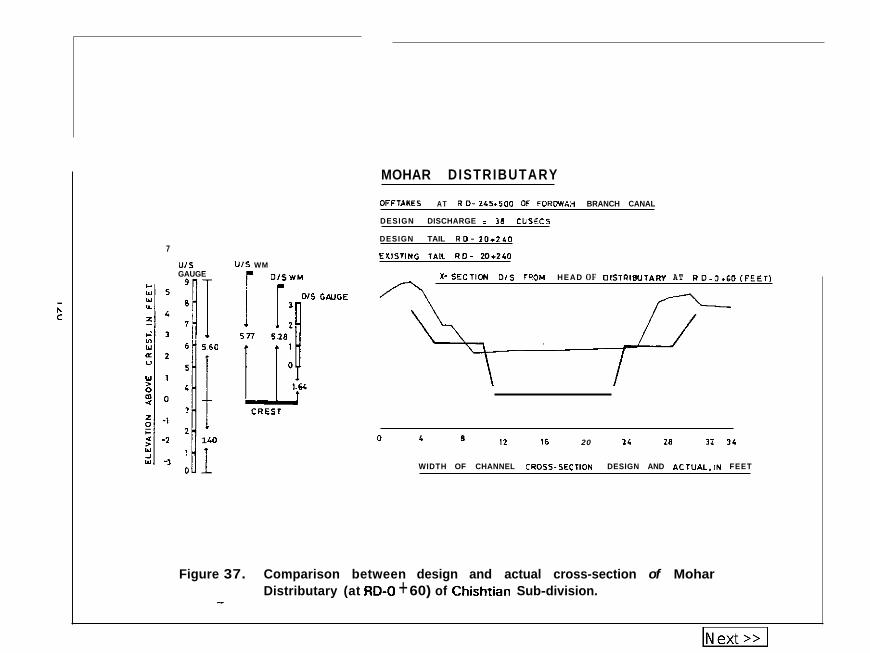
Sedimentatioii is a big problem in the Chishtian Sub-division. During closure period of every year, people get sediment ( 1 to 3 feet deep1 from Fordwah Branch Canal wi th tractors trollies or donkey carts f rom different reaches as shown in Figure 35. Most of the distributaries receive 1 to 2 feet of sediment each year. Therefore, Gauge Readers have dif f iculty running these tlistributaries according to their design discharge. The estimated depth of sediment lying on the bed o f distributary channels in Chishtian Sub-divisioii is (j iveti in Table 33. The sedimentation varies considerably between distributaries. However, the comparison of actual and design w id th (cross- section) of each channel (distributary) just downstream f rom the head regulators above the crests are presented in Figures 36 to 49. The present position of the gauges are also presented in these figures with reference to the crests.
116
'c 0 0 0 0 t
c m
c c ._ E -0 QJ v)
m C
QJ m
._ c c
E m
117
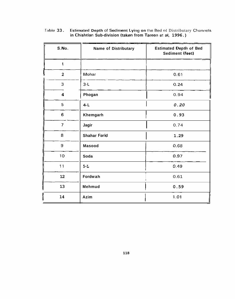
rabk 33. tstirnattxl Depth of Sedinient Lying on the Bcd 0 1 Distributary Clwvicls in Chishtian Sub-division (taken from Tarcen et al. 1996.)
Name of Distributary S.No. L Estimated Deplli of Bed Sediment [feet)
II 2
4 II
12
13
14 II
0.94 I Phogan
4- L I 0.20
0.93 I Khemgarh
Jagir ~ ~
0.74 I 1.29 I Shahar Farid
Masood
Soda
5-L
0.61 I Ford w a h
0.59 I Mehmud
I Azim
118
- e W w Y - 8
d
N
0
m c Q
% U 4 c 3 m
c
0
U. 0 0 4 W I
I 0 U u.
VI
0
a
I
. z 0 c U Y n
\
-
7
U I S GAUGE
c u s Y Y
r ' l Y) Y - 2 " Y 1 >
1 40 Y
Y -1
U I S WM r D I S W M c
MOHAR DISTRIBUTARY
DFFTAIES AT R 0- 245t500 OF FDRWAH BRANCH CANAL
DESIGN DISCHARGE I 18 CUSEC5
DESIGN TAIL R D - 7 0 1 2 & 0
EXISTING TAIL I D - M+240
I -SECTICN D1S FROM HEAD OF 01STllBUTAW AT R D - J . G O ( F E E T 1 n
! i
' 12 16 20 24 18 I2 Y L 0 8
WIDTH OF CHANNEL CROSS-SEC?lDN DESIGN AND ACTUAL.IN FEET
Figure 37. Comparison between design and actual cross-section of Mohar Distributary (at RD-0 + 60) of Chishtian Sub-division. -