Embed Size (px)
Citation preview
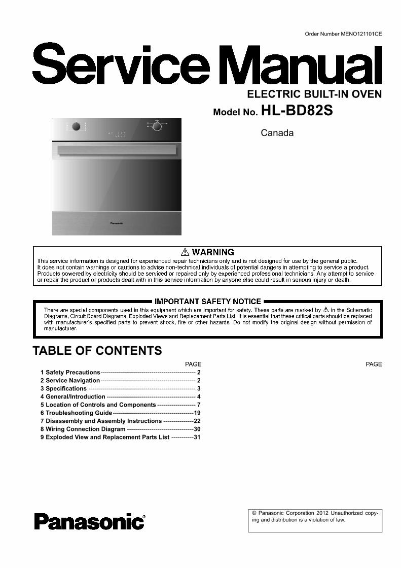
Order Number MENO121101CE
ELECTRIC BUILT-IN OVENModel No. HL-BD82S
Canada
TABLE OF CONTENTSPAGE PAGE
1 Safety Precautions----------------------------------------------- 22 Service Navigation ----------------------------------------------- 23 Specifications ----------------------------------------------------- 34 General/Introduction -------------------------------------------- 45 Location of Controls and Components ------------------- 76 Troubleshooting Guide ----------------------------------------197 Disassembly and Assembly Instructions ---------------228 Wiring Connection Diagram ---------------------------------309 Exploded View and Replacement Parts List -----------31
© Panasonic Corporation 2012 Unauthorized copy-ing and distribution is a violation of law.
HL-BD82S
1 Safety Precautions1.1. Health & SafetyNote: When servicing the SCHOLTES oven, health and safety issues must be considered at all times. Specific safety issues are listed below with their appropriate icon. These are illustrated throughout the service information to remind service people of the health and safety issues
1.1.1. Electrical Safety
1.1.2. Electrostatic Discharge
1.1.3. Good Working Practices
1.1.4. Insulation Test
1.1.5. Sheet Metal Edges
2 Service Navigation2.1. Special Tools & Materials2.1.1. Tools
• 7.5V Power Screw/Nut Driver Recommended• 3 inch socket extension bar• 7mm socket• 10mm socket• 12mm socket• Flexible shaft socket extension• #1 and #2 Short Phillips Screw driver• Digital power meter (Voltage — Current)• Static strap
2.1.2. Materials• Ceramic spacers• Ceramic fiber gasket for upper element• Ceramic fiber gasket for ring element• Nylon spacers for display board
2
HL-BD82S
3 Specifications3.1. Oven Specifications3.1.1. Oven WeightSingle 30 inchbs /Kg = 181/82
3.1.2. Power rating
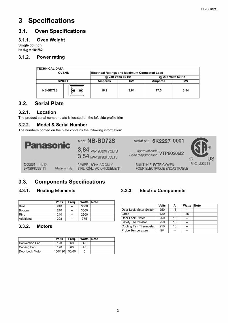
3.2. Serial Plate3.2.1. LocationThe product serial number plate is located on the left side profile trim
3.2.2. Model & Serial NumberThe numbers printed on the plate contains the following information:
3.3. Components Specifications 3.3.1. Heating Elements
3.3.2. Motors
3.3.3. Electric Components
TECHNICAL DATAOVENS Electrical Ratings and Maximum Connected Load
@ 240 Volts 60 Hz @ 208 Volts 60 HzSINGLE Amperes kW Amperes kW
NB-BD72S 16.9 3.84 17.5 3.54
Volts Freq. Watts NoteBroil 240 -- 3500Bottom 240 -- 3000Ring 240 -- 2500Additional 208 -- 775
Volts Freq. Watts NoteConvection Fan 120 60 45Cooling Fan 120 60 45Door Lock Motor 100/120 50/60 5
Volts A Watts NoteDoor Lock Motor Switch 250 16 --Lamp 120 -- 25Door Lock Switch 250 16 --Safety Thermostat 250 16 --Cooling Fan Thermostat 250 16 --Probe Temperature 5V -- --
3
HL-BD82S
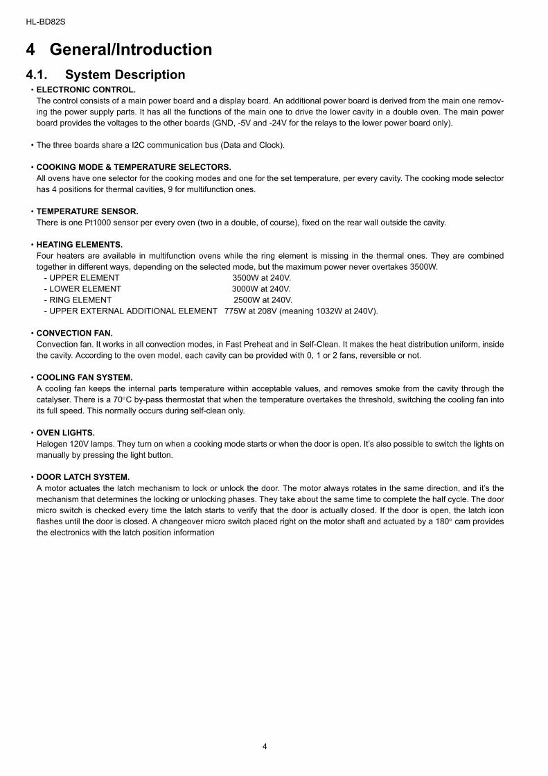
4 General/Introduction4.1. System Description
• ELECTRONIC CONTROL.The control consists of a main power board and a display board. An additional power board is derived from the main one remov-ing the power supply parts. It has all the functions of the main one to drive the lower cavity in a double oven. The main powerboard provides the voltages to the other boards (GND, -5V and -24V for the relays to the lower power board only).
• The three boards share a I2C communication bus (Data and Clock).
• COOKING MODE & TEMPERATURE SELECTORS.All ovens have one selector for the cooking modes and one for the set temperature, per every cavity. The cooking mode selectorhas 4 positions for thermal cavities, 9 for multifunction ones.
• TEMPERATURE SENSOR.There is one Pt1000 sensor per every oven (two in a double, of course), fixed on the rear wall outside the cavity.
• HEATING ELEMENTS.Four heaters are available in multifunction ovens while the ring element is missing in the thermal ones. They are combinedtogether in different ways, depending on the selected mode, but the maximum power never overtakes 3500W.
- UPPER ELEMENT 3500W at 240V. - LOWER ELEMENT 3000W at 240V. - RING ELEMENT 2500W at 240V. - UPPER EXTERNAL ADDITIONAL ELEMENT 775W at 208V (meaning 1032W at 240V).
• CONVECTION FAN.Convection fan. It works in all convection modes, in Fast Preheat and in Self-Clean. It makes the heat distribution uniform, insidethe cavity. According to the oven model, each cavity can be provided with 0, 1 or 2 fans, reversible or not.
• COOLING FAN SYSTEM.A cooling fan keeps the internal parts temperature within acceptable values, and removes smoke from the cavity through thecatalyser. There is a 70°C by-pass thermostat that when the temperature overtakes the threshold, switching the cooling fan intoits full speed. This normally occurs during self-clean only.
• OVEN LIGHTS.Halogen 120V lamps. They turn on when a cooking mode starts or when the door is open. It’s also possible to switch the lights onmanually by pressing the light button.
• DOOR LATCH SYSTEM.A motor actuates the latch mechanism to lock or unlock the door. The motor always rotates in the same direction, and it’s themechanism that determines the locking or unlocking phases. They take about the same time to complete the half cycle. The doormicro switch is checked every time the latch starts to verify that the door is actually closed. If the door is open, the latch iconflashes until the door is closed. A changeover micro switch placed right on the motor shaft and actuated by a 180° cam providesthe electronics with the latch position information
4
HL-BD82S
4.2. Oven Model Set Up and Configuration The control must be able to drive multifunction cavities, with one or two convection fans, and thermal cavities. Different oven mod-els are possible as described in the following table.
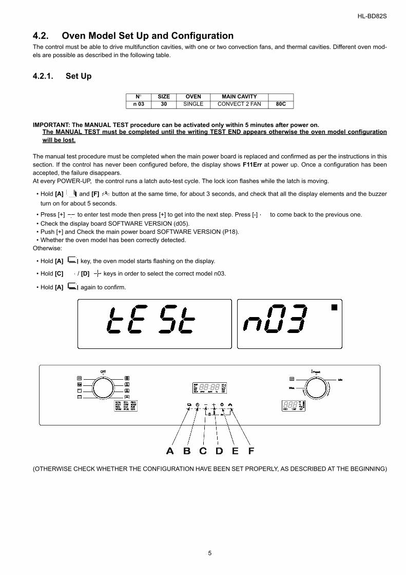
4.2.1. Set Up
IMPORTANT: The MANUAL TEST procedure can be activated only within 5 minutes after power on. The MANUAL TEST must be completed until the writing TEST END appears otherwise the oven model configurationwill be lost.
The manual test procedure must be completed when the main power board is replaced and confirmed as per the instructions in thissection. If the control has never been configured before, the display shows F11Err at power up. Once a configuration has beenaccepted, the failure disappears.At every POWER-UP, the control runs a latch auto-test cycle. The lock icon flashes while the latch is moving.
• Hold [A] and [F] button at the same time, for about 3 seconds, and check that all the display elements and the buzzerturn on for about 5 seconds.
• Press [+] to enter test mode then press [+] to get into the next step. Press [-] to come back to the previous one.• Check the display board SOFTWARE VERSION (d05). • Push [+] and Check the main power board SOFTWARE VERSION (P18).• Whether the oven model has been correctly detected.
Otherwise:
• Hold [A] key, the oven model starts flashing on the display.
• Hold [C] / [D] keys in order to select the correct model n03.
• Hold [A] again to confirm.
(OTHERWISE CHECK WHETHER THE CONFIGURATION HAVE BEEN SET PROPERLY, AS DESCRIBED AT THE BEGINNING)
N° SIZE OVEN MAIN CAVITYn 03 30 SINGLE CONVECT 2 FAN 80C
5
HL-BD82S
4.2.2. Configuration
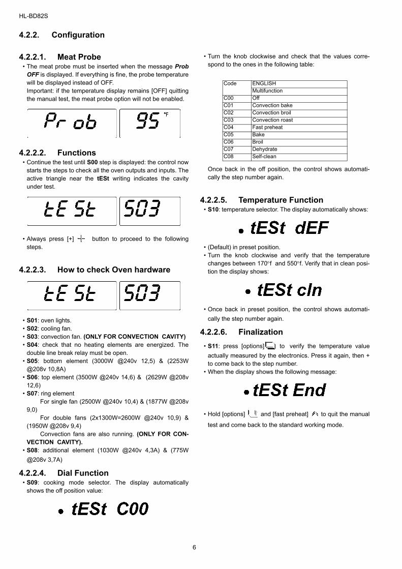
4.2.2.1. Meat Probe• The meat probe must be inserted when the message Prob
OFF is displayed. If everything is fine, the probe temperaturewill be displayed instead of OFF. Important: if the temperature display remains [OFF] quittingthe manual test, the meat probe option will not be enabled.
4.2.2.2. Functions• Continue the test until S00 step is displayed: the control now
starts the steps to check all the oven outputs and inputs. Theactive triangle near the tESt writing indicates the cavityunder test.
• Always press [+] button to proceed to the followingsteps.
4.2.2.3. How to check Oven hardware
• S01: oven lights.• S02: cooling fan. • S03: convection fan. (ONLY FOR CONVECTION CAVITY) • S04: check that no heating elements are energized. The
double line break relay must be open. • S05: bottom element (3000W @240v 12,5) & (2253W
@208v 10,8A) • S06: top element (3500W @240v 14,6) & (2629W @208v
12,6) • S07: ring element
For single fan (2500W @240v 10,4) & (1877W @208v9,0)
For double fans (2x1300W=2600W @240v 10,9) &(1950W @208v 9,4)
Convection fans are also running. (ONLY FOR CON-VECTION CAVITY).
• S08: additional element (1030W @240v 4,3A) & (775W@208v 3,7A)
4.2.2.4. Dial Function• S09: cooking mode selector. The display automatically
shows the off position value:
• Turn the knob clockwise and check that the values corre-spond to the ones in the following table:
Once back in the off position, the control shows automati-cally the step number again.
4.2.2.5. Temperature Function• S10: temperature selector. The display automatically shows:
• (Default) in preset position. • Turn the knob clockwise and verify that the temperature
changes between 170°f and 550°f. Verify that in clean posi-tion the display shows:
• Once back in preset position, the control shows automati-cally the step number again.
4.2.2.6. Finalization• S11: press [options] to verify the temperature value
actually measured by the electronics. Press it again, then +to come back to the step number.
• When the display shows the following message:
• Hold [options] and [fast preheat] to quit the manual
test and come back to the standard working mode.
Code ENGLISHMultifunction
C00 OffC01 Convection bakeC02 Convection broilC03 Convection roastC04 Fast preheatC05 BakeC06 BroilC07 DehydrateC08 Self-clean
6
HL-BD82S
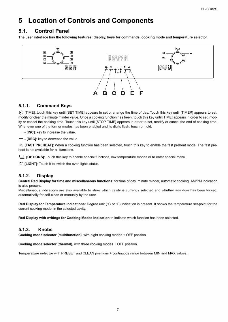
5 Location of Controls and Components5.1. Control PanelThe user interface has the following features: display, keys for commands, cooking mode and temperature selector
5.1.1. Command Keys [TIME]: touch this key until [SET TIME] appears to set or change the time of day. Touch this key until [TIMER] appears to set,
modify or clear the minute minder value. Once a cooking function has been, touch this key until [TIME] appears in order to set, mod-ify or cancel the cooking time. Touch this key until [STOP TIME] appears in order to set, modify or cancel the end of cooking time.Whenever one of the former modes has been enabled and its digits flash, touch or hold:
- [INC]: key to increase the value.
- [DEC]: key to decrease the value.
[FAST PREHEAT]: When a cooking function has been selected, touch this key to enable the fast preheat mode. The fast pre-heat is not available for all functions.
[OPTIONS]: Touch this key to enable special functions, low temperature modes or to enter special menu.
[LIGHT]: Touch it to switch the oven lights status.
5.1.2. DisplayCentral Red Display for time and miscellaneous functions: for time of day, minute minder, automatic cooking. AM/PM indicationis also present.Miscellaneous indications are also available to show which cavity is currently selected and whether any door has been locked,automatically for self-clean or manually by the user.
Red Display for Temperature indications: Degree unit (°C or °F) indication is present. It shows the temperature set-point for thecurrent cooking mode, in the selected cavity.
Red Display with writings for Cooking Modes indication to indicate which function has been selected.
5.1.3. KnobsCooking mode selector (multifunction), with eight cooking modes + OFF position.
Cooking mode selector (thermal), with three cooking modes + OFF position.
Temperature selector with PRESET and CLEAN positions + continuous range between MIN and MAX values.
7
HL-BD82S
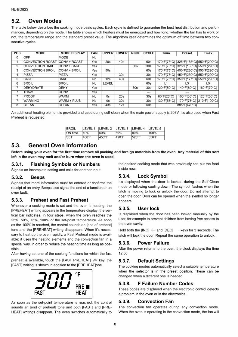
5.2. Oven ModesThe table below describes the cooking mode basic cycles. Each cycle is defined to guarantee the best heat distribution and perfor-mances, depending on the mode. The table shows which heaters must be energized and how long, whether the fan has to work ornot, the temperature range and the standard preset value. The algorithm itself determines the optimum off time between two con-secutive cycles.
An additional heating element is provided and used during self-clean when the main power supply is 208V. It’s also used when FastPreheat is requested.
5.3. General Oven Information Before using your oven for the first time remove all packing and foreign materials from the oven. Any material of this sortleft in the oven may melt and/or burn when the oven is used.
5.3.1. Flashing Symbols or NumbersSignals an incomplete setting and calls for another input.
5.3.2. BeepsSignals that more information must be entered or confirms thereceipt of an entry. Beeps also signal the end of a function or anoven fault.
5.3.3. Preheat and Fast PreheatWhenever a cooking mode is set and the oven is heating, the[PREHEAT] writing appears in the temperature display: the ver-tical bar indicates, in four steps, when the oven reaches the25%, 50%, 75%, 100% of the set-point temperature. As soonas the 100% is reached, the control sounds an [end of preheat]tone and the [PREHEAT] writing disappears. When it’s neces-sary to heat up the oven rapidly, a Fast Preheat mode is avail-able: it uses the heating elements and the convection fan in aspecial way, in order to reduce the heating time as long as pos-sible.After having set one of the cooking functions for which the fast
preheat is available, touch the [FAST PREHEAT] key, the[FAST] writing is shown in addition to the [PREHEAT]one.
As soon as the set-point temperature is reached, the controlsounds an [end of preheat] tone and both [FAST] and [PRE-HEAT] writings disappear. The oven switches automatically to
the desired cooking mode that was previously set: put the foodinside now.
5.3.4. Lock SymbolIt’s displayed when the door is locked, during the Self-Cleanmode or following cooling down. The symbol flashes when thelatch is moving to lock or unlock the door. Do not attempt toopen the door. Door can be opened when the symbol no longerappears.
5.3.5. User lockIs displayed when the door has been locked manually by theuser, for example to prevent children from having free access tothe oven cavity.
Hold both the [INC] and [DEC] keys for 3 seconds. Thelatch will lock the door. Repeat the same operation to unlock.
5.3.6. Power FailureAfter the power returns to the oven, the clock displays the time12.00
5.3.7. Default SettingsThe cooking modes automatically select a suitable temperaturewhen the selector is in the preset position. These can bechanged when a different one is needed.
5.3.8. F Failure Number CodesThese codes are displayed when the electronic control detectsa problem in the oven or in the electronics.
5.3.9. Convection FanThe convection fan operates during any convection mode.When the oven is operating in the convection mode, the fan will
POS MODE MODE DISPLAY FAN UPPER LOWER RING CYCLE Tmin Preset Tmax0 OFF MODE No1 CONVECTION ROAST CONV + ROAST Yes 20s 40s 60s 170°F(75°C) 325°F(165°C) 550°F(290°C)2 CONVECTION BAKE CONV + BAKE Yes 30s 30s 170°F(75°C) 325°F(165°C) 550°F(290°C)3 CONVECTION BROIL CONV + BROIL Yes 50s 60s 170°F(75°C) 450°F(230°C) 550°F(290°C)4 PIZZA PIZZA Yes 30s 30s 170°F(75°C) 450°F(230°C) 550°F(290°C)5 BAKE BAKE No 12s 40s 60s 170°F(75°C) 350°F(177°C) 550°F(290°C)6 BROIL BROIL No LEVEL 60s L1 L3 L57 DEHYDRATE DEHY Yes 30s 30s 120°F(50°C) 140°F(60°C) 160°F(70°C)7 THAW CONV Yes --- ---7 PROOF WARM No 0s 20s 30s 80°F(25°C) 100°F(35°C) 120°F(50°C)7 WARMING WARM + PLUS No 0s 30s 30s 130°F(55°C) 170°F(75°C) 210°F(100°C)8 CLEAN CLEAN Yes 43s 12s 60s 885°F(470°C)
BROIL LEVEL 1 LEVEL 2 LEVEL 3 LEVEL 4 LEVEL 5ON time 40% 50% 60% 80% 100%SET 400°F 450°F 490°F 520°F 550°F
8
HL-BD82S
turn off automatically when the door is opened. The convectionfan will run during the preheat time.
5.3.10. Component Cooling FanActivates during any cooking or self-cleaning mode to cool inner components and outer door surfaces. This air is exhausted through the vent located above the oven door. It continues to run until components have cooled sufficiently. The cooling fan speed gets high in self-clean and whenever the
internal components temperature becomes high.
5.3.11. Locking the KeyboardHold both the keys indicated by [KEYBD. LOCK] legend for 3seconds. Commands are now locked and [SENS LOCK] will bedisplayed every time you touch any keys.Repeat the same operation for 3 seconds to unlock the key-board.
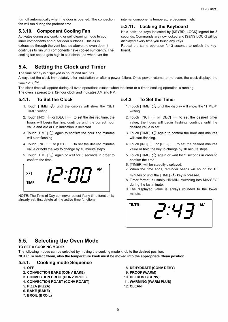
5.4. Setting the Clock and Timer The time of day is displayed in hours and minutes.Always set the clock immediately after installation or after a power failure. Once power returns to the oven, the clock displays thetime 12:00AM.The clock time will appear during all oven operations except when the timer or a timed cooking operation is running.The oven is preset to a 12-hour clock and indicates AM and PM.
5.4.1. To Set the Clock1. Touch [TIME] until the display will show the “SET
TIME” writing.
2. Touch [INC] or [DEC] to set the desired time, thehours will begin flashing: continue until the correct hourvalue and AM or PM indication is selected.
3. Touch [TIME] again to confirm the hour and minuteswill start flashing.
4. Touch [INC] or [DEC] to set the desired minutesvalue or hold the key to change by 10 minute steps.
5. Touch [TIME] again or wait for 5 seconds in order toconfirm the time.
NOTE: The Time of Day can never be set if any time function is already set: first delete all the active time functions.
5.4.2. To Set the Timer1. Touch [TIME] until the display will show the “TIMER”
writing.
2. Touch [INC] or [DEC] to set the desired timervalue, the hours will begin flashing: continue until thedesired value is set.
3. Touch [TIME] again to confirm the hour and minuteswill start flashing.
4. Touch [INC] or [DEC] to set the desired minutesvalue or hold the key to change by 10 minute steps.
5. Touch [TIME] again or wait for 5 seconds in order toconfirm the time.
6. [TIMER] will be steadily displayed.7. When the time ends, reminder beeps will sound for 15
minutes or until the [TIME] key is pressed. 8. Timer format is usually HR:MIN, switching into MIN:SEC
during the last minute.9. The displayed value is always rounded to the lower
minute.
5.5. Selecting the Oven Mode TO SET A COOKING MODE:The following modes can be selected by moving the cooking mode knob to the desired position.NOTE: To select Clean, also the temperature knob must be moved into the appropriate Clean position.
5.5.1. Cooking mode Sequence1. OFF2. CONVECTION BAKE (CONV BAKE)3. CONVECTION BROIL (CONV BROIL)4. CONVECTION ROAST (CONV ROAST)5. PIZZA (PIZZA)6. BAKE (BAKE)7. BROIL (BROIL)
8. DEHYDRATE (CONV DEHY)9. PROOF (WARM)
10. DEFROST (CONV)11. WARMING (WARM PLUS)12. CLEAN
9

HL-BD82S
5.5.2. Using [OPTIONS] key to select low temperature functions
Moving the cooking mode selector to Low Temp position one ofthe following functions is displayed:
1. DEHYDRATE (CONV DEHY)2. PROOF (WARM)3. DEFROST (CONV)4. WARMING (WARM PLUS)
Touch [OPTIONS] key to toggle between these four modes. The last used is kept in memory for the next selection.
5.5.3. Temperature Selector • Select the desired temperature moving the selector or leave
it in the PRESET position if the proposed value is fine. The temperature can be changed by 5°F or 5°C steps.
• As soon as one of the knobs is moved, the control switches automatically to display the value in the correspondent cav-ity. The corresponding writing [UPPER] or [LOWER] appears.
• Cavity will begin to heat, the [ON] writing is displayed whenthe selected oven is active, oven lights will turn on.
• [PREHEAT] writing will turn on. Once the oven has pre-heated, it will beep and switch the writing off.
• To change the temperature while cooking, simply turn the
temperature knob until the display shows the desired value. • Move the cooking mode selector to OFF if you intend to stop
cooking
The triangles in the upper right corner of the display are activewhen a cavity is running, even if it is not selected on the display.
5.5.4. Using Oven Light • A single light key activates the lights in either oven.
• If [LIGHT] key is touched when both ovens are off, lightsin both the upper and lower oven will turn on. Touch [LIGHT]
key again, and both oven lights will turn off. • Oven lights turn on and off automatically when the door is
opened and closed. • When an oven is in use, oven lights turn on automatically
when a mode is started. Oven lights will turn off automati-cally when the oven mode is cancelled.
• The lights do not operate in the Self-Clean mode.
5.6. Time Oven Mode Operation • In double oven models, both ovens can be set independently to operate a timed mode.• Be sure that the time-of-day clock is displaying the correct time.• The timed mode turns off the oven at the end of the cook time.
5.6.1. To Set Time Mode1. Select the cooking mode and the temperature by means
of the knobs. The “ON” writing will appear in the display.
2. Touch [TIME] key until the “TIME” writings will appearin the display.
3. Touch [INC] or [DEC] , the hour digits will beginflashing. Continue to set the desired cooking time. Keepin mind that the time required for the oven to reach thetemperature must be included in the set cooking time.
4. Touch [TIME] again, the hours will be confirmed andthe minute digits will begin flashing.
5. Touch [INC] or [DEC] to change the minutes. Holdthe key to change by 10 minutes steps. Continue to setthe desired cooking time.
6. Touch [TIME] once again or wait for a few seconds toconfirm the cooking time value.
5.6.2. To Delay the Start of a Timed Mode Follow steps 1 through 6 or 7 above.
1. Touch [TIME] key until [STOP TIME] will appear in thedisplay.
2. The control automatically calculates and display the initial
value, adding the cooking time already set to the time ofday.
3. Touch [INC] or [DEC] , the hour digits will beginflashing. Continue to set the desired stop time.
4. Touch [TIME] again, the hours will be confirmed andthe minute digits will begin flashing.
5. Touch [INC] or [DEC] to change the minutes. Holdthe key to change by 10 minutes steps. Continue to setthe desired stop time.
6. Touch [TIME] once again or wait for a few seconds toconfirm the stop time value.
7. The clock automatically calculates the time of day atwhich the mode starts and stops. The [DELAY] writing isdisplayed until the starting time is reached.
10
HL-BD82S
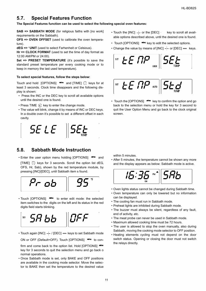
5.7. Special Features Function The Special Features function can be used to select the following special oven features:
SAB => SABBATH MODE (for religious faiths with [no work]requirements on the Sabbath).OFS => OVEN OFFSET (used to calibrate the oven tempera-ture).dEG => °UNIT (used to select Farhenheit or Celsious).Hr => CLOCK FORMAT (used to set the time of day format as12:00 AM/PM or 24:00).Set => PRESET TEMPERATURE (it’s possible to save thestandard preset temperature per every cooking mode or tokeep in memory the last used temperature). To select special features, follow the steps below:
Touch and hold [OPTIONS] and [TIME] keys for atleast 3 seconds. Clock time disappears and the following dis-play is shown:
• Press the INC or the DEC key to scroll all available optionsuntil the desired one is found.
• Press TIME key to enter the change mode.• The value will blink, change it by means of INC or DEC keys.
In a double oven it’s possible to set a different offset in eachcavity.
• Touch the [INC] or the [DEC] key to scroll all avail-able options described above, until the desired one is found.
• Touch [OPTIONS] key to edit the selected options.
• Change the value by means of [INC] or [DEC] keys.
• Touch the [OPTIONS] key to confirm the option and goback to the selection menu or hold the key for 3 second toquit the User Option Menu and go back to the clock originalscreen.
5.8. Sabbath Mode Instruction • Enter the user option menu holding [OPTIONS] and
[TIME] keys for 3 seconds. Scroll the option list dEG,OFS, Hr, Sab), shown by the red temperature module, bypressing [INC]/[DEC], until Sabbath item s found.
• Touch [OPTIONS] to enter edit mode: the selecteditem switches to the digits on the left and its status in the reddigits field starts blinking.
• Touch again [INC] / [DEC] keys to set Sabbath mode
ON or OFF (Default=OFF). Touch [OPTIONS] to con-
firm and come back to the option list. Hold [OPTIONS]key for 3 seconds to quit the selection menu and go back onormal operations.
• Once Sabbath mode is set, only BAKE and OFF positionsare available in the cooking mode selector. Move the selec-tor to BAKE then set the temperature to the desired value
within 5 minutes. • After 5 minutes, the temperature cannot be shown any more
and the display appears as below: Sabbath mode is active.
• Oven lights status cannot be changed during Sabbath time. • Oven temperature can only be lowered but no information
can be displayed.• The cooling fan must run in Sabbath mode. • Preheat lights are inhibited during Sabbath mode. • The buzzer must always be silent, regardless of any fault,
end of activity, etc. • The meat probe can never be used in Sabbath mode. • Maximum allowed cooking time must be 72 hours. • The user is allowed to stop the oven manually, also during
Sabbath, moving the cooking mode selector to OFF position. • Heating elements cycling must not depend on the door
switch status. Opening or closing the door must not switchthe relays directly.
11
HL-BD82S
5.9. Setting the Self Clean Mode 5.9.1. To set the Self Clean Mode
1. Rotate both knobs into the clean position. 2. CLEAN & TIME appear. 3. The clean time is displayed automatically, its standard
value is 3 hours. 4. At the end of the programmed cleaning time, the oven will
automatically turn off. 5. To stop the cleaning mode at any moment, move one of
the two knobs from the cleaning position. Do not attempt to open the door while the door is locked. The[AUTO LOCK] writings will flash until the motor stops. Whenthey are displayed, the door cannot be opened. Check that thedoor has been locked and will not open before starting the Self-Clean mode.If door does not lock, rotate the cooking mode knob into theOFF position and do not start self-clean; phone for service.If the door is in the open position when this mode is selected,the [AUTO LOCK] writings will flash until the door is closed. Thelatch doesn’t move.
5.9.2. To change the Clean Time 1. To change the setting from 3 hours, select either 2 hours
for light soil or 4 hours for heavy soil immediately beforestarting.
2. To change the hours, touch the [TIME] key. 3. The hours will flash.
4. Use [INC] or [DEC] keys to change the value.
5. To change the minutes, touch the [TIME] key again. 6. The minutes will flash.
7. Use [INC] or [DEC] keys to change the value.Hold the key to change by 10 minutes steps.
8. Touch [TIME] or wait a few seconds to confirm thenew value.
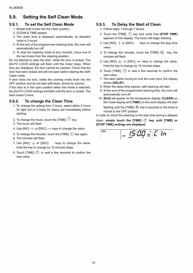
5.9.3. To Delay the Start of Clean 1. Follow steps 1 through 7 above.
2. Touch the [TIME] key and verify that [STOP TIME]appears on the display. The hours will begin flashing.
3. Use [INC] or [DEC] keys to change the stop timevalue.
4. To change the minutes, touch the [TIME] key, theminutes will flash.
5. Use [INC] or [DEC] keys to change the value.Hold the key to change by 10 minutes steps.
6. Touch [TIME] or wait a few seconds to confirm thenew value.
7. The latch starts moving to lock the oven door, the displayshows [DELAY].
8. When the delay time expires, self-cleaning will start. 9. At the end of the programmed cleaning time, the oven will
automatically turn off. 10. [End] will appear on the temperature display, [CLEAN] on
the mode display and [TIME] on the clock display will start
flashing until the [TIME] key is touched or the knob ismoved to the OFF position.
In order to check the cleaning or the stop time during a delayed
clean, simply touch the [TIME] key until [TIME] or[STOP TIME] writings are displayed.
12
HL-BD82S
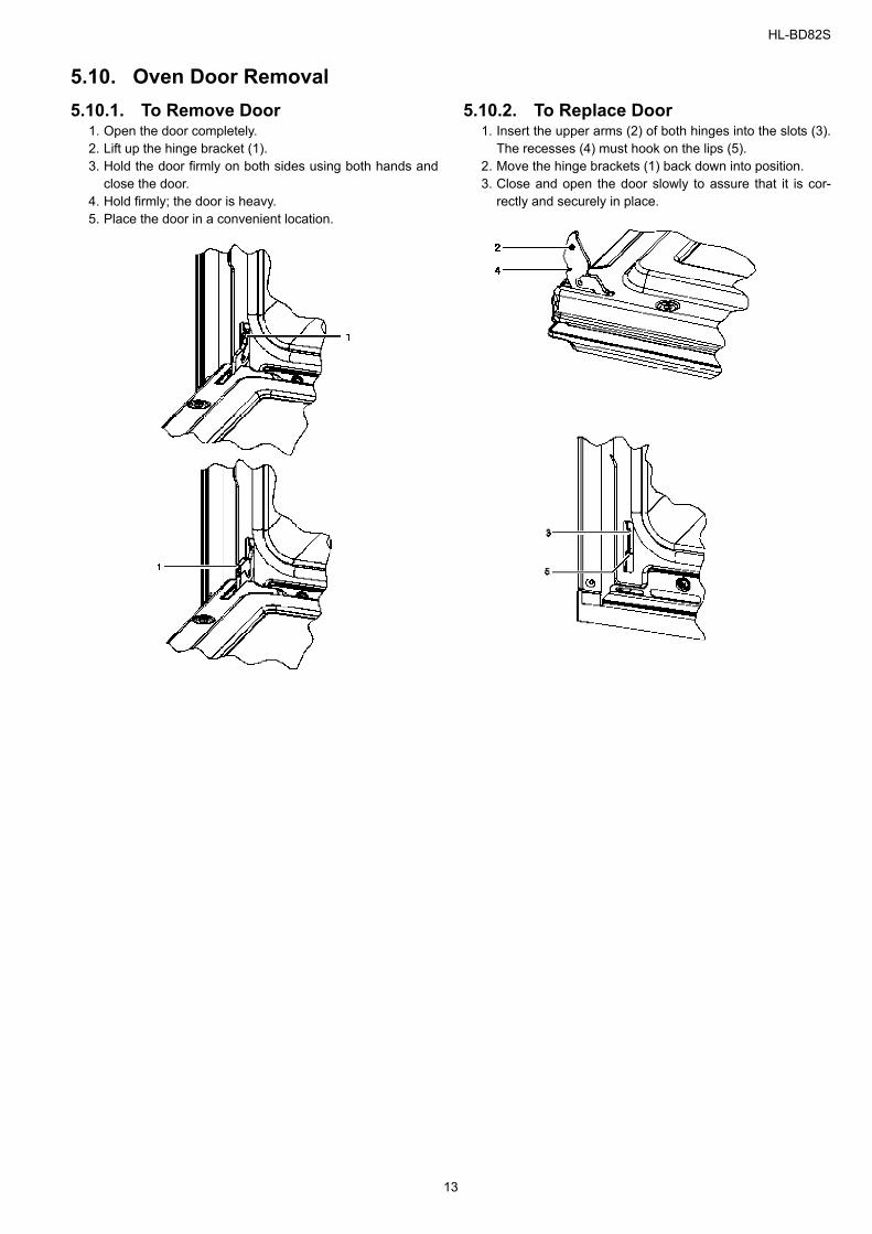
5.10. Oven Door Removal 5.10.1. To Remove Door
1. Open the door completely. 2. Lift up the hinge bracket (1). 3. Hold the door firmly on both sides using both hands and
close the door. 4. Hold firmly; the door is heavy. 5. Place the door in a convenient location.
5.10.2. To Replace Door1. Insert the upper arms (2) of both hinges into the slots (3).
The recesses (4) must hook on the lips (5). 2. Move the hinge brackets (1) back down into position. 3. Close and open the door slowly to assure that it is cor-
rectly and securely in place.
13
HL-BD82S
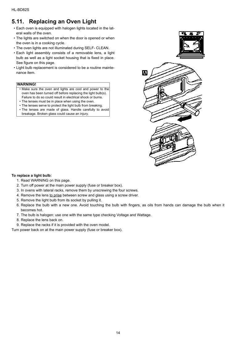
5.11. Replacing an Oven Light • Each oven is equipped with halogen lights located in the lat-
eral walls of the oven.• The lights are switched on when the door is opened or when
the oven is in a cooking cycle.• The oven lights are not illuminated during SELF- CLEAN.• Each light assembly consists of a removable lens, a light
bulb as well as a light socket housing that is fixed in place.See figure on this page.
• Light bulb replacement is considered to be a routine mainte-nance item.
To replace a light bulb:1. Read WARNING on this page. 2. Turn off power at the main power supply (fuse or breaker box). 3. In ovens with lateral racks, remove them by unscrewing the four screws. 4. Remove the lens to prise between screw and glass using a screw driver. 5. Remove the light bulb from its socket by pulling it. 6. Replace the bulb with a new one. Avoid touching the bulb with fingers, as oils from hands can damage the bulb when it
becomes hot. 7. The bulb is halogen: use one with the same type checking Voltage and Wattage. 8. Replace the lens back on. 9. Replace the racks if it is provided with the oven model.
Turn power back on at the main power supply (fuse or breaker box).
WARNING!• Make sure the oven and lights are cool and power to the
oven has been turned off before replacing the light bulb(s). Failure to do so could result in electrical shock or burns.
• The lenses must be in place when using the oven.• The lenses serve to protect the light bulb from breaking.• The lenses are made of glass. Handle carefully to avoid
breakage. Broken glass could cause an injury.
14
HL-BD82S
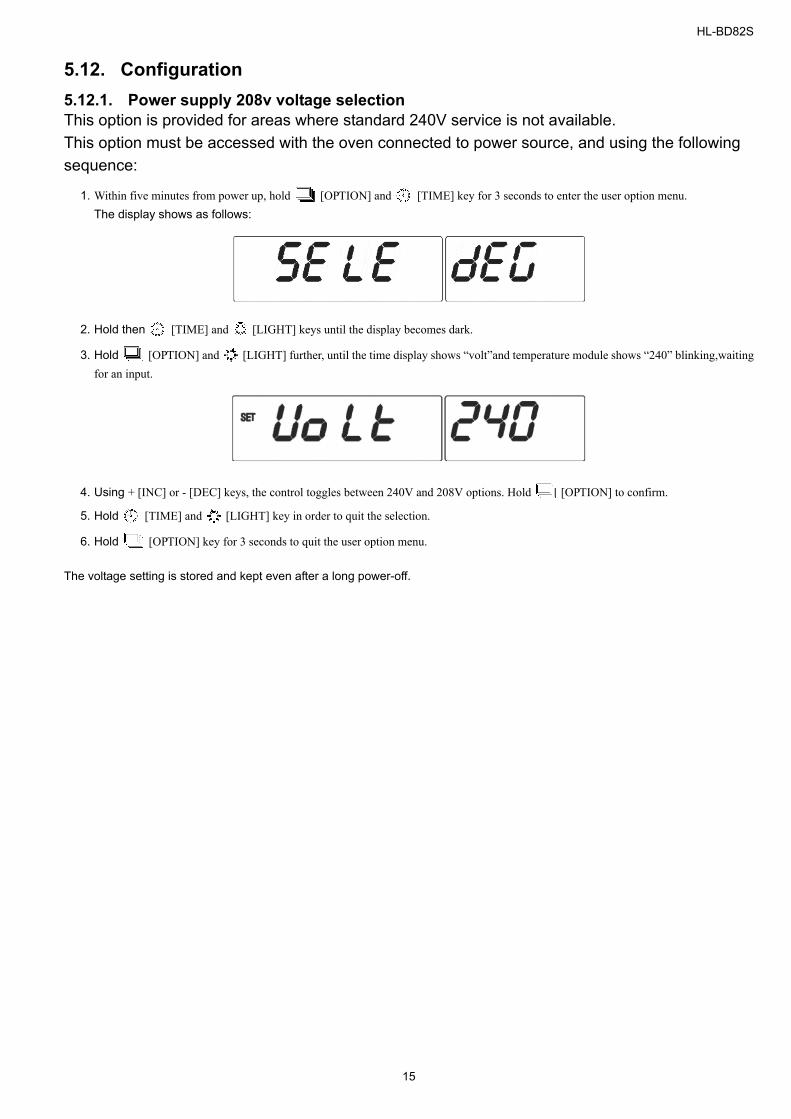
5.12. Configuration 5.12.1. Power supply 208v voltage selectionThis option is provided for areas where standard 240V service is not available.This option must be accessed with the oven connected to power source, and using the following sequence:
1. Within five minutes from power up, hold [OPTION] and [TIME] key for 3 seconds to enter the user option menu. The display shows as follows:
2. Hold then [TIME] and [LIGHT] keys until the display becomes dark.
3. Hold [OPTION] and [LIGHT] further, until the time display shows “volt”and temperature module shows “240” blinking,waitingfor an input.
4. Using + [INC] or - [DEC] keys, the control toggles between 240V and 208V options. Hold [OPTION] to confirm.
5. Hold [TIME] and [LIGHT] key in order to quit the selection.
6. Hold [OPTION] key for 3 seconds to quit the user option menu.
The voltage setting is stored and kept even after a long power-off.
15
HL-BD82S
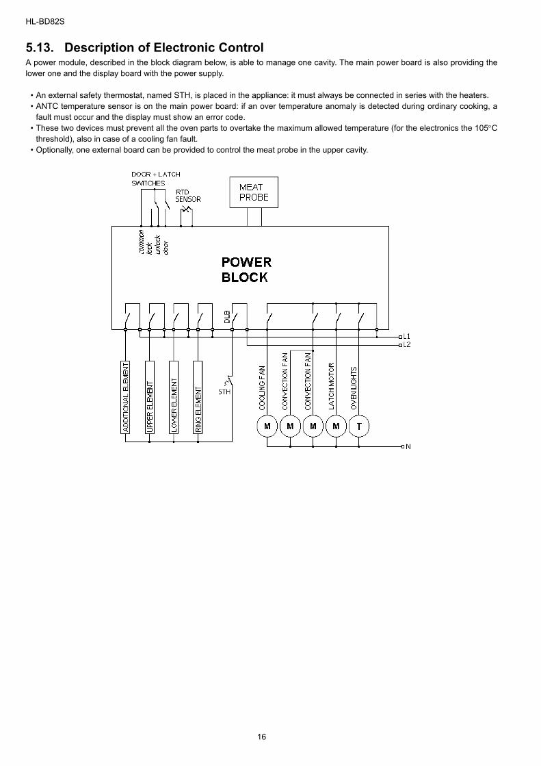
5.13. Description of Electronic Control A power module, described in the block diagram below, is able to manage one cavity. The main power board is also providing thelower one and the display board with the power supply.
• An external safety thermostat, named STH, is placed in the appliance: it must always be connected in series with the heaters. • ANTC temperature sensor is on the main power board: if an over temperature anomaly is detected during ordinary cooking, a
fault must occur and the display must show an error code. • These two devices must prevent all the oven parts to overtake the maximum allowed temperature (for the electronics the 105°C
threshold), also in case of a cooling fan fault.• Optionally, one external board can be provided to control the meat probe in the upper cavity.
16
HL-BD82S
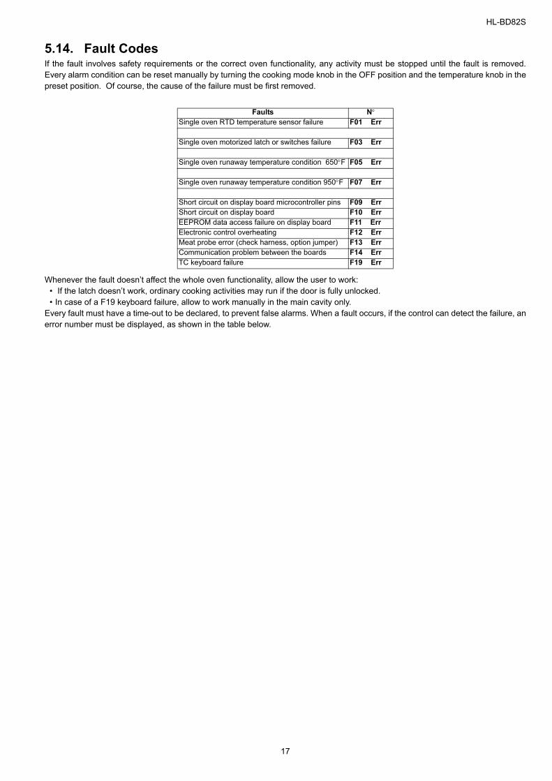
5.14. Fault Codes If the fault involves safety requirements or the correct oven functionality, any activity must be stopped until the fault is removed.Every alarm condition can be reset manually by turning the cooking mode knob in the OFF position and the temperature knob in thepreset position. Of course, the cause of the failure must be first removed.
Whenever the fault doesn’t affect the whole oven functionality, allow the user to work:• If the latch doesn’t work, ordinary cooking activities may run if the door is fully unlocked.• In case of a F19 keyboard failure, allow to work manually in the main cavity only.
Every fault must have a time-out to be declared, to prevent false alarms. When a fault occurs, if the control can detect the failure, anerror number must be displayed, as shown in the table below.
Faults N°Single oven RTD temperature sensor failure F01 Err
Single oven motorized latch or switches failure F03 Err
Single oven runaway temperature condition 650°F F05 Err
Single oven runaway temperature condition 950°F F07 Err
Short circuit on display board microcontroller pins F09 ErrShort circuit on display board F10 ErrEEPROM data access failure on display board F11 ErrElectronic control overheating F12 ErrMeat probe error (check harness, option jumper) F13 ErrCommunication problem between the boards F14 ErrTC keyboard failure F19 Err
17
HL-BD82S
5.15. Oven Safety Features 5.15.1. Child - safe locking systemAll of our ovens are built-in child-safe locking systems. Thefuture is automatically enabled any time the appliance is con-nected to the power, any time the switch is turned on and anytime the oven is programmed to run a self-cleaning of the cav-ity.The same future it can be is used on the manual mode in thehousehold where a minor is present to prevent children fromgetting in touch with hot parts. The function of this future isexplained in details on the chapter 5.3.5.User lock.
5.15.2. Over heating sensorAll of our ovens are built with a over heating sensor system:
• we have two bi-metal mechanical thermostats for each cav-ity.
• an electronic sensor [NTC] or [negative temperature coeffi-cients] mounted on the main power board (see chapter5.13.Description of Electronic Control for more informa-tion). The role of the [NTC] is to protect the electronic boardsof an eventually over-heating. (the [NTC] varies with the val-ues of voltage, only DC, values tabulated at 5.13.Descriptionof Electronic Control)
An electronic [PTC] or [positive temperature coefficients] probemounted on the inside of the cavity who is responsible of theinside cavity reading of the temperature. (the [PTC] varies withthe resistance — tabulated at chapter...)
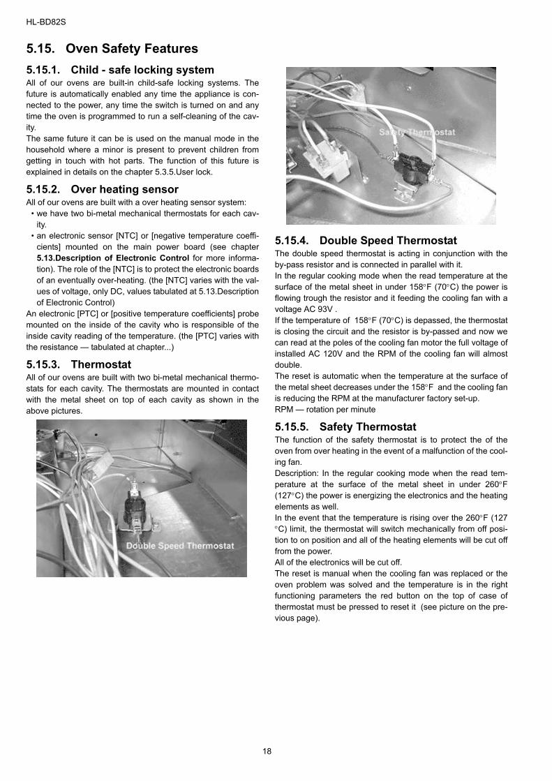
5.15.3. Thermostat All of our ovens are built with two bi-metal mechanical thermo-stats for each cavity. The thermostats are mounted in contactwith the metal sheet on top of each cavity as shown in theabove pictures.
5.15.4. Double Speed ThermostatThe double speed thermostat is acting in conjunction with theby-pass resistor and is connected in parallel with it.In the regular cooking mode when the read temperature at thesurface of the metal sheet in under 158°F (70°C) the power isflowing trough the resistor and it feeding the cooling fan with avoltage AC 93V . If the temperature of 158°F (70°C) is depassed, the thermostatis closing the circuit and the resistor is by-passed and now wecan read at the poles of the cooling fan motor the full voltage ofinstalled AC 120V and the RPM of the cooling fan will almostdouble.The reset is automatic when the temperature at the surface ofthe metal sheet decreases under the 158°F and the cooling fanis reducing the RPM at the manufacturer factory set-up.RPM — rotation per minute
5.15.5. Safety ThermostatThe function of the safety thermostat is to protect the of theoven from over heating in the event of a malfunction of the cool-ing fan.Description: In the regular cooking mode when the read tem-perature at the surface of the metal sheet in under 260°F(127°C) the power is energizing the electronics and the heatingelements as well. In the event that the temperature is rising over the 260°F (127°C) limit, the thermostat will switch mechanically from off posi-tion to on position and all of the heating elements will be cut offfrom the power. All of the electronics will be cut off.The reset is manual when the cooling fan was replaced or theoven problem was solved and the temperature is in the rightfunctioning parameters the red button on the top of case ofthermostat must be pressed to reset it (see picture on the pre-vious page).
18
HL-BD82S
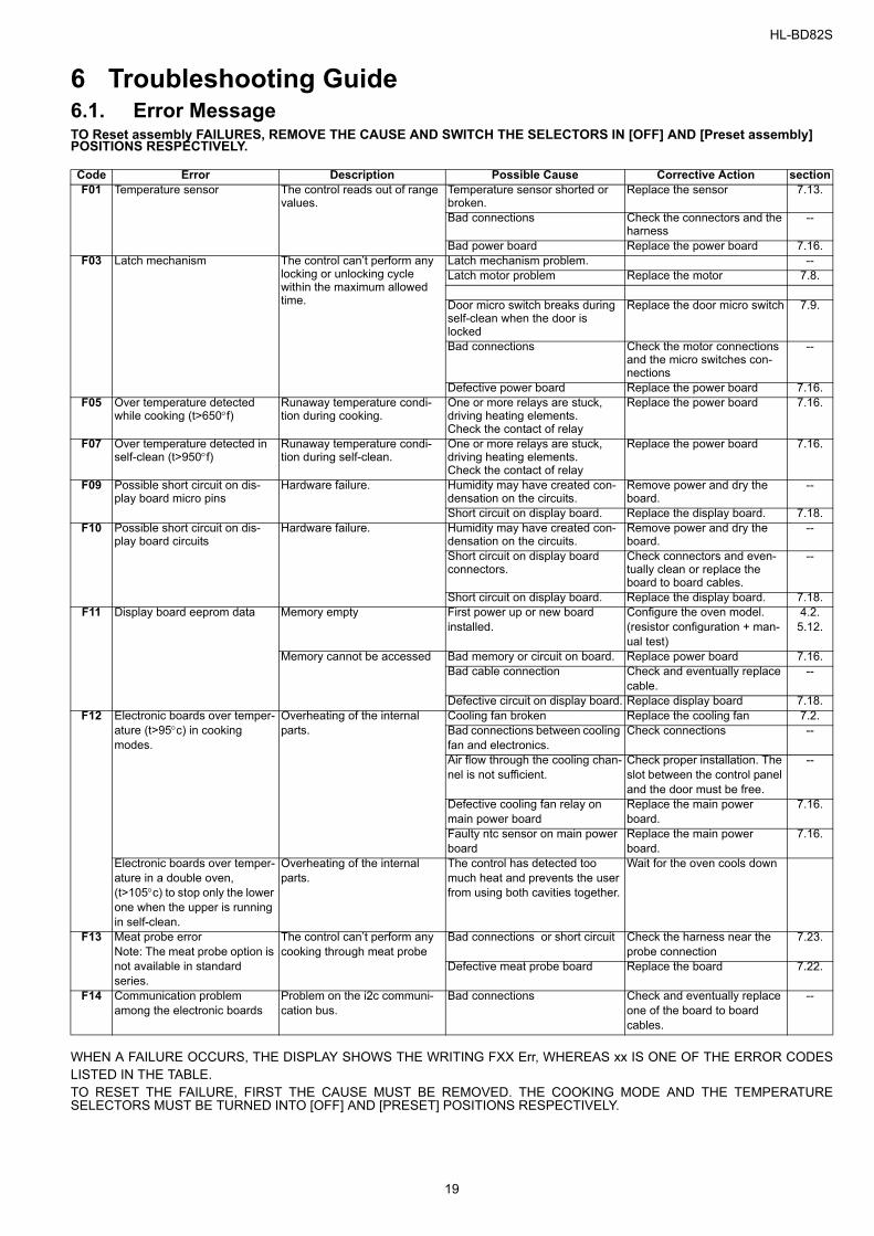
6 Troubleshooting Guide6.1. Error MessageTO Reset assembly FAILURES, REMOVE THE CAUSE AND SWITCH THE SELECTORS IN [OFF] AND [Preset assembly] POSITIONS RESPECTIVELY.
WHEN A FAILURE OCCURS, THE DISPLAY SHOWS THE WRITING FXX Err, WHEREAS xx IS ONE OF THE ERROR CODESLISTED IN THE TABLE. TO RESET THE FAILURE, FIRST THE CAUSE MUST BE REMOVED. THE COOKING MODE AND THE TEMPERATURESELECTORS MUST BE TURNED INTO [OFF] AND [PRESET] POSITIONS RESPECTIVELY.
Code Error Description Possible Cause Corrective Action sectionF01 Temperature sensor The control reads out of range
values.Temperature sensor shorted or broken.
Replace the sensor 7.13.
Bad connections Check the connectors and the harness
--
Bad power board Replace the power board 7.16.F03 Latch mechanism The control can’t perform any
locking or unlocking cycle within the maximum allowed time.
Latch mechanism problem. --Latch motor problem Replace the motor 7.8.
Door micro switch breaks during self-clean when the door is locked
Replace the door micro switch 7.9.
Bad connections Check the motor connections and the micro switches con-nections
--
Defective power board Replace the power board 7.16.F05 Over temperature detected
while cooking (t>650°f)Runaway temperature condi-tion during cooking.
One or more relays are stuck, driving heating elements.Check the contact of relay
Replace the power board 7.16.
F07 Over temperature detected in self-clean (t>950°f)
Runaway temperature condi-tion during self-clean.
One or more relays are stuck, driving heating elements.Check the contact of relay
Replace the power board 7.16.
F09 Possible short circuit on dis-play board micro pins
Hardware failure. Humidity may have created con-densation on the circuits.
Remove power and dry the board.
--
Short circuit on display board. Replace the display board. 7.18.F10 Possible short circuit on dis-
play board circuitsHardware failure. Humidity may have created con-
densation on the circuits. Remove power and dry the board.
--
Short circuit on display board connectors.
Check connectors and even-tually clean or replace the board to board cables.
--
Short circuit on display board. Replace the display board. 7.18.F11 Display board eeprom data Memory empty First power up or new board
installed.Configure the oven model.(resistor configuration + man-ual test)
4.2.5.12.
Memory cannot be accessed Bad memory or circuit on board. Replace power board 7.16.Bad cable connection Check and eventually replace
cable.--
Defective circuit on display board. Replace display board 7.18.F12 Electronic boards over temper-
ature (t>95°c) in cooking modes.
Overheating of the internal parts.
Cooling fan broken Replace the cooling fan 7.2.Bad connections between cooling fan and electronics.
Check connections --
Air flow through the cooling chan-nel is not sufficient.
Check proper installation. The slot between the control panel and the door must be free.
--
Defective cooling fan relay on main power board
Replace the main power board.
7.16.
Faulty ntc sensor on main power board
Replace the main power board.
7.16.
Electronic boards over temper-ature in a double oven, (t>105°c) to stop only the lower one when the upper is running in self-clean.
Overheating of the internal parts.
The control has detected too much heat and prevents the user from using both cavities together.
Wait for the oven cools down
F13 Meat probe error Note: The meat probe option is not available in standard series.
The control can’t perform any cooking through meat probe
Bad connections or short circuit Check the harness near the probe connection
7.23.
Defective meat probe board Replace the board 7.22.
F14 Communication problem among the electronic boards
Problem on the i2c communi-cation bus.
Bad connections Check and eventually replace one of the board to board cables.
--
19
HL-BD82S
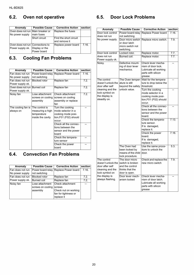
6.2. Oven not operative
6.3. Cooling Fan Problems
6.4. Convection Fan Problems
6.5. Door Lock Problems
Anomaly Possible Cause Corrective Action sectionOven does not run No power supply
Main breaker or main fuses
Replace the fuses
Short circuit Find the short circuit and remove it
Oven does not run Power supply ok.
Connections to Display or the Power board
Replace power board 7.16.
Anomaly Possible Cause Corrective Action sectionFan does not run No power supply
Power board relay not switching
Replace Power board 7.16.
Fan does not run Power supply ok.
Blocked rotor Replace fan 7.2.
Oven does not run Power supply ok.
Burned coil Replace fan 7.2.
Noisy fan Lose attachment screws on cooling assembly
Check attachment screws on cooling assembly or replace fan
7.2.
The cooling fan is always on
The control is measuring a high temperature inside the cavity
Turn the cooking mode selector in a cooking mode posi-tion,F01 (F02) should occur.
--
Check all the connec-tions between the sensor and the power board
--
Check the tempera-ture sensor
--
Check the power board
--
Anomaly Possible Cause Corrective Action sectionFan does not run No power supply
Power board relay not switching
Replace Power board 7.16.
Fan does not run Power supply ok.
Blocked rotor Replace fan 7.2.Burned coil Replace fan 7.2.
Noisy fan Lose attachment screws on cooling assembly
Check attachment screws Check nut on working fan for tightness or replace it
--
Anomaly Possible Cause Corrective Action sectionDoor lock control does not runNo power supply.
Power board relay not switching
Replace Power board 7.16.
Door micro switch or door latch micro switch not switching.
Replace micro switch. 7.9.
Door lock control does not runPower supply ok.
Locked rotor. Replace motor. 7.7.Burned coil. Replace motor. 7.7.
Noisy. Defective mount-ing of door lever mechanics.
Check lever mecha-nism of door lock.Lubricate all working parts with silicon grease
--
The control doesn’t unlock the door after self cleaning and the lock symbol on the display is steadily on.
The Oven temper-ature is still beyond the safety unlock value.
Wait for the tempera-ture to drop below the threshold.
--
Turn the cooking mode selector in a cooking mode posi-tion,F01 (F02) should occur.
--
Check all the connec-tions between the sensor and the power board.
--
Check the tempera-ture sensor. If is damaged, replace it.
7.13.
Check the power board.If is damaged, replace it.
7.16.
The Oven had been locked by means of the child lock procedure.
Use the same proce-dure to unlock the door.
5.3.
The control doesn’t unlock the door after self cleaning and the lock symbol on the display is always flashing.
The door micro switch is broken and the control thinks that the door is open.
Check and replace the new micro switch
7.9.
Door lever mech-anism locked
Check lever mecha-nism of door latch.Lubricate all working parts with silicon grease
--
20
HL-BD82S
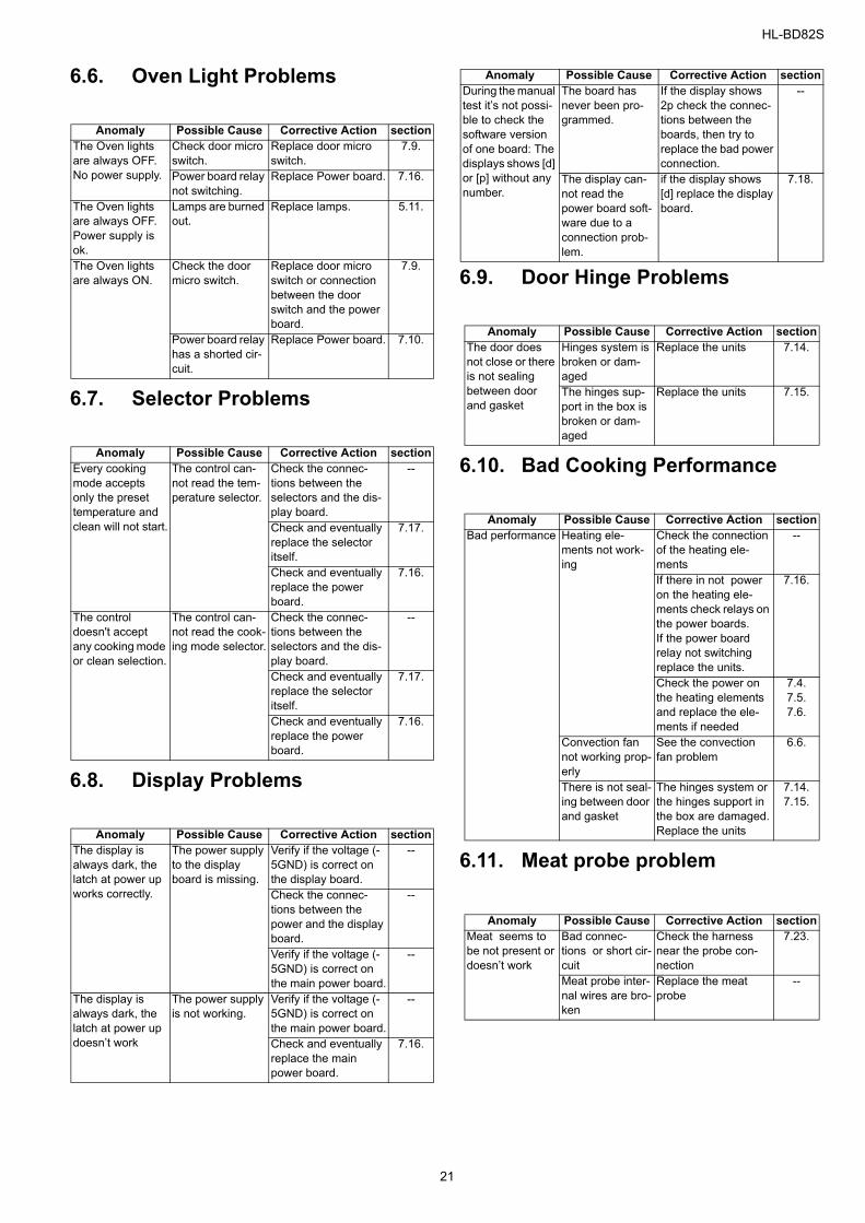
6.6. Oven Light Problems
6.7. Selector Problems
6.8. Display Problems
6.9. Door Hinge Problems
6.10. Bad Cooking Performance
6.11. Meat probe problem
Anomaly Possible Cause Corrective Action sectionThe Oven lights are always OFF.No power supply.
Check door micro switch.
Replace door micro switch.
7.9.
Power board relay not switching.
Replace Power board. 7.16.
The Oven lights are always OFF.Power supply is ok.
Lamps are burned out.
Replace lamps. 5.11.
The Oven lights are always ON.
Check the door micro switch.
Replace door micro switch or connection between the door switch and the power board.
7.9.
Power board relay has a shorted cir-cuit.
Replace Power board. 7.10.
Anomaly Possible Cause Corrective Action sectionEvery cooking mode accepts only the preset temperature and clean will not start.
The control can-not read the tem-perature selector.
Check the connec-tions between the selectors and the dis-play board.
--
Check and eventually replace the selector itself.
7.17.
Check and eventually replace the power board.
7.16.
The control doesn't accept any cooking mode or clean selection.
The control can-not read the cook-ing mode selector.
Check the connec-tions between the selectors and the dis-play board.
--
Check and eventually replace the selector itself.
7.17.
Check and eventually replace the power board.
7.16.
Anomaly Possible Cause Corrective Action sectionThe display is always dark, the latch at power up works correctly.
The power supply to the display board is missing.
Verify if the voltage (-5GND) is correct on the display board.
--
Check the connec-tions between the power and the display board.
--
Verify if the voltage (-5GND) is correct on the main power board.
--
The display is always dark, the latch at power up doesn’t work
The power supply is not working.
Verify if the voltage (-5GND) is correct on the main power board.
--
Check and eventually replace the main power board.
7.16.
During the manual test it’s not possi-ble to check the software version of one board: The displays shows [d] or [p] without any number.
The board has never been pro-grammed.
If the display shows 2p check the connec-tions between the boards, then try to replace the bad power connection.
--
The display can-not read the power board soft-ware due to a connection prob-lem.
if the display shows [d] replace the display board.
7.18.
Anomaly Possible Cause Corrective Action sectionThe door does not close or there is not sealing between door and gasket
Hinges system is broken or dam-aged
Replace the units 7.14.
The hinges sup-port in the box is broken or dam-aged
Replace the units 7.15.
Anomaly Possible Cause Corrective Action sectionBad performance Heating ele-
ments not work-ing
Check the connection of the heating ele-ments
--
If there in not power on the heating ele-ments check relays on the power boards.If the power board relay not switching replace the units.
7.16.
Check the power on the heating elements and replace the ele-ments if needed
7.4.7.5.7.6.
Convection fan not working prop-erly
See the convection fan problem
6.6.
There is not seal-ing between door and gasket
The hinges system or the hinges support in the box are damaged.Replace the units
7.14.7.15.
Anomaly Possible Cause Corrective Action sectionMeat seems to be not present or doesn’t work
Bad connec-tions or short cir-cuit
Check the harness near the probe con-nection
7.23.
Meat probe inter-nal wires are bro-ken
Replace the meat probe
--
Anomaly Possible Cause Corrective Action section
21
HL-BD82S
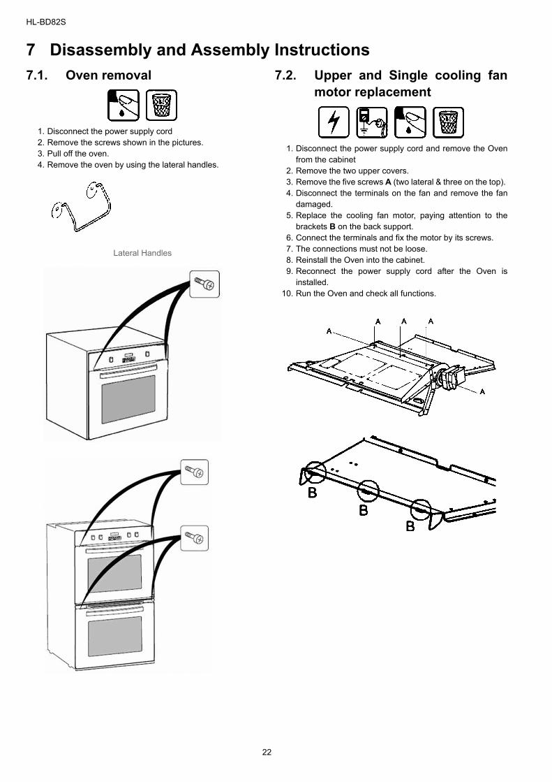
7 Disassembly and Assembly Instructions7.1. Oven removal
1. Disconnect the power supply cord 2. Remove the screws shown in the pictures. 3. Pull off the oven. 4. Remove the oven by using the lateral handles.
Lateral Handles
7.2. Upper and Single cooling fanmotor replacement
1. Disconnect the power supply cord and remove the Ovenfrom the cabinet
2. Remove the two upper covers.3. Remove the five screws A (two lateral & three on the top). 4. Disconnect the terminals on the fan and remove the fan
damaged. 5. Replace the cooling fan motor, paying attention to the
brackets B on the back support. 6. Connect the terminals and fix the motor by its screws.7. The connections must not be loose. 8. Reinstall the Oven into the cabinet. 9. Reconnect the power supply cord after the Oven is
installed. 10. Run the Oven and check all functions.
22
HL-BD82S
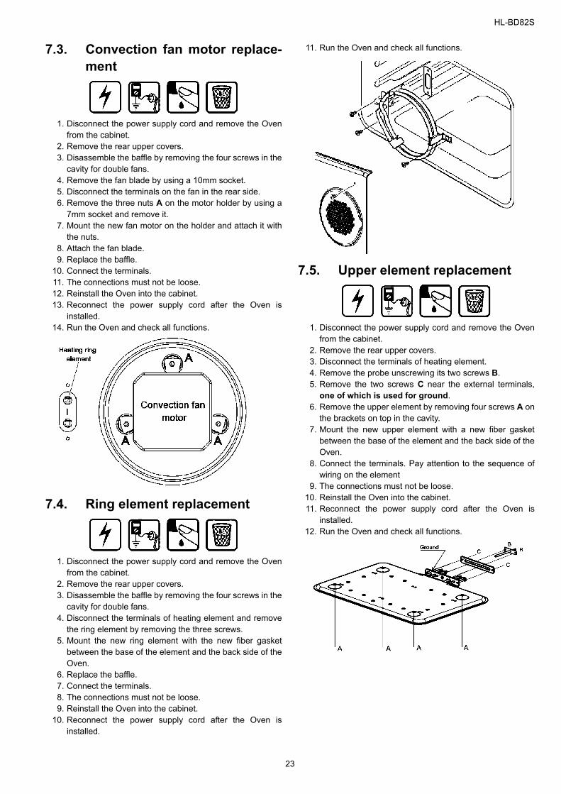
7.3. Convection fan motor replace-ment
1. Disconnect the power supply cord and remove the Ovenfrom the cabinet.
2. Remove the rear upper covers.3. Disassemble the baffle by removing the four screws in the
cavity for double fans. 4. Remove the fan blade by using a 10mm socket. 5. Disconnect the terminals on the fan in the rear side. 6. Remove the three nuts A on the motor holder by using a
7mm socket and remove it. 7. Mount the new fan motor on the holder and attach it with
the nuts. 8. Attach the fan blade.9. Replace the baffle.
10. Connect the terminals. 11. The connections must not be loose. 12. Reinstall the Oven into the cabinet. 13. Reconnect the power supply cord after the Oven is
installed. 14. Run the Oven and check all functions.
7.4. Ring element replacement
1. Disconnect the power supply cord and remove the Ovenfrom the cabinet.
2. Remove the rear upper covers.3. Disassemble the baffle by removing the four screws in the
cavity for double fans. 4. Disconnect the terminals of heating element and remove
the ring element by removing the three screws. 5. Mount the new ring element with the new fiber gasket
between the base of the element and the back side of theOven.
6. Replace the baffle.7. Connect the terminals. 8. The connections must not be loose.9. Reinstall the Oven into the cabinet.
10. Reconnect the power supply cord after the Oven isinstalled.
11. Run the Oven and check all functions.
7.5. Upper element replacement
1. Disconnect the power supply cord and remove the Ovenfrom the cabinet.
2. Remove the rear upper covers. 3. Disconnect the terminals of heating element. 4. Remove the probe unscrewing its two screws B. 5. Remove the two screws C near the external terminals,
one of which is used for ground. 6. Remove the upper element by removing four screws A on
the brackets on top in the cavity. 7. Mount the new upper element with a new fiber gasket
between the base of the element and the back side of theOven.
8. Connect the terminals. Pay attention to the sequence ofwiring on the element
9. The connections must not be loose. 10. Reinstall the Oven into the cabinet. 11. Reconnect the power supply cord after the Oven is
installed. 12. Run the Oven and check all functions.
23
HL-BD82S
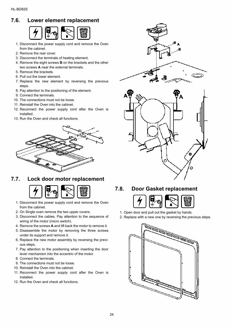
7.6. Lower element replacement
1. Disconnect the power supply cord and remove the Ovenfrom the cabinet.
2. Remove the rear cover. 3. Disconnect the terminals of heating element.4. Remove the eight screws B on the brackets and the other
two screws A near the external terminals.5. Remove the brackets.6. Pull out the lower element.7. Replace the new element by reversing the previous
steps.8. Pay attention to the positioning of the element.9. Connect the terminals.
10. The connections must not be loose.11. Reinstall the Oven into the cabinet.12. Reconnect the power supply cord after the Oven is
installed.13. Run the Oven and check all functions.
7.7. Lock door motor replacement
1. Disconnect the power supply cord and remove the Ovenfrom the cabinet.
2. On Single oven remove the two upper covers. 3. Disconnect the cables. Pay attention to the sequence of
wiring of the motor (micro switch). 4. Remove the screws A and lift back the motor to remove it. 5. Disassemble the motor by removing the three screws
under its support and remove it. 6. Replace the new motor assembly by reversing the previ-
ous steps. 7. Pay attention to the positioning when inserting the door
lever mechanism into the eccentric of the motor. 8. Connect the terminals. 9. The connections must not be loose.
10. Reinstall the Oven into the cabinet. 11. Reconnect the power supply cord after the Oven is
installed. 12. Run the Oven and check all functions.
7.8. Door Gasket replacement
1. Open door and pull out the gasket by hands. 2. Replace with a new one by reversing the previous steps.
24
HL-BD82S
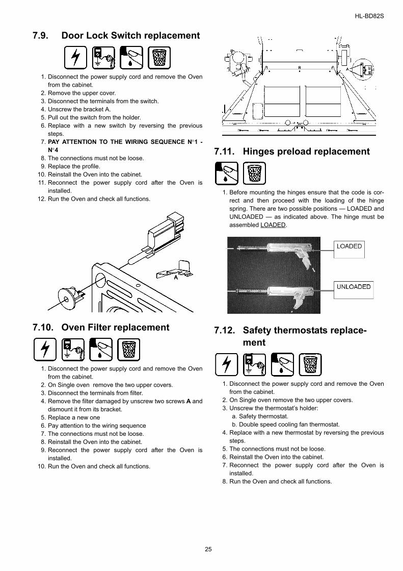
7.9. Door Lock Switch replacement
1. Disconnect the power supply cord and remove the Ovenfrom the cabinet.
2. Remove the upper cover. 3. Disconnect the terminals from the switch. 4. Unscrew the bracket A. 5. Pull out the switch from the holder. 6. Replace with a new switch by reversing the previous
steps. 7. PAY ATTENTION TO THE WIRING SEQUENCE N°1 -
N°4 8. The connections must not be loose. 9. Replace the profile.
10. Reinstall the Oven into the cabinet. 11. Reconnect the power supply cord after the Oven is
installed. 12. Run the Oven and check all functions.
7.10. Oven Filter replacement
1. Disconnect the power supply cord and remove the Ovenfrom the cabinet.
2. On Single oven remove the two upper covers. 3. Disconnect the terminals from filter. 4. Remove the filter damaged by unscrew two screws A and
dismount it from its bracket. 5. Replace a new one 6. Pay attention to the wiring sequence 7. The connections must not be loose. 8. Reinstall the Oven into the cabinet. 9. Reconnect the power supply cord after the Oven is
installed. 10. Run the Oven and check all functions.
7.11. Hinges preload replacement
1. Before mounting the hinges ensure that the code is cor-rect and then proceed with the loading of the hingespring. There are two possible positions — LOADED andUNLOADED — as indicated above. The hinge must beassembled LOADED.
7.12. Safety thermostats replace-ment
1. Disconnect the power supply cord and remove the Ovenfrom the cabinet.
2. On Single oven remove the two upper covers. 3. Unscrew the thermostat’s holder:
a. Safety thermostat.b. Double speed cooling fan thermostat.
4. Replace with a new thermostat by reversing the previoussteps.
5. The connections must not be loose.6. Reinstall the Oven into the cabinet. 7. Reconnect the power supply cord after the Oven is
installed. 8. Run the Oven and check all functions.
25
HL-BD82S
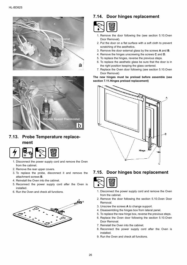
7.13. Probe Temperature replace-ment
1. Disconnect the power supply cord and remove the Ovenfrom the cabinet.
2. Remove the rear upper covers. 3. To replace the probe, disconnect it and remove the
attachment screws B. 4. Reinstall the Oven into the cabinet. 5. Reconnect the power supply cord after the Oven is
installed. 6. Run the Oven and check all functions.
7.14. Door hinges replacement
1. Remove the door following the (see section 5.10.OvenDoor Removal).
2. Put the door on a flat surface with a soft cloth to preventscratching of the aesthetics.
3. Remove the door external glass by the screws A and B. 4. Remove the hinges unscrewing the screws C and D. 5. To replace the hinges, reverse the previous steps. 6. To replace the aesthetic glass be sure that the door is in
the right position keeping the glass centered. 7. Replace the Oven door following (see section 5.10.Oven
Door Removal) The new hinges must be preload before assemble (seesection 7.11.Hinges preload replacement)
7.15. Door hinges box replacement
1. Disconnect the power supply cord and remove the Ovenfrom the cabinet.
2. Remove the door following the section 5.10.Oven DoorRemoval.
3. Unscrew the screws A to change support. 4. Disassembling the hinges box from lateral panel. 5. To replace the new hinge box, reverse the previous steps. 6. Replace the Oven door following the section 5.10.Oven
Door Removal. 7. Reinstall the Oven into the cabinet. 8. Reconnect the power supply cord after the Oven is
installed. 9. Run the Oven and check all functions.
26
HL-BD82S
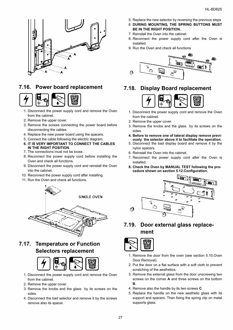
7.16. Power board replacement
1. Disconnect the power supply cord and remove the Ovenfrom the cabinet.
2. Remove the upper cover. 3. Remove the screws connecting the power board before
disconnecting the cables. 4. Replace the new power board using the spacers. 5. Connect the cable following the electric diagram. 6. IT IS VERY IMPORTANT TO CONNECT THE CABLES
IN THE RIGHT POSITION.7. The connections must not be loose. 8. Reconnect the power supply cord before installing the
Oven and check all functions. 9. Disconnect the power supply cord and reinstall the Oven
into the cabinet. 10. Reconnect the power supply cord after installing. 11. Run the Oven and check all functions.
7.17. Temperature or Function Selectors replacement
1. Disconnect the power supply cord and remove the Ovenfrom the cabinet.
2. Remove the upper cover. 3. Remove the knobs and the glass by its screws on the
sides.4. Disconnect the bad selector and remove it by the screws
remove also its spacer.
5. Replace the new selector by reversing the previous steps 6. DURING MOUNTING, THE SPRING BUTTONS MUST
BE IN THE RIGHT POSITION.7. Reinstall the Oven into the cabinet. 8. Reconnect the power supply cord after the Oven is
installed. 9. Run the Oven and check all functions
7.18. Display Board replacement
1. Disconnect the power supply cord and remove the Ovenfrom the cabinet.
2. Remove the upper cover. 3. Remove the knobs and the glass by its screws on the
sides. 4. Before to remove one of lateral display remove previ-
ously the selector above it to facilitate the operation.5. Disconnect the bad display board and remove it by the
nylon spacers. 6. Reinstall the Oven into the cabinet. 7. Reconnect the power supply cord after the Oven is
installed. 8. Check the Oven by MANUAL TEST following the pro-
cedure shown on section 5.12.Configuration.
7.19. Door external glass replace-ment
1. Remove the door from the oven (see section 5.10.OvenDoor Removal).
2. Put the door on a flat surface with a soft cloth to preventscratching of the aesthetics.
3. Remove the external glass from the door unscrewing twoscrews on the corner A and three screws on the bottomB.
4. Remove also the handle by its two screws C. 5. Replace the handle on the new aesthetic glass with its
support and spacers. Than fixing the spring clip on metalsupports glass.
27
HL-BD82S
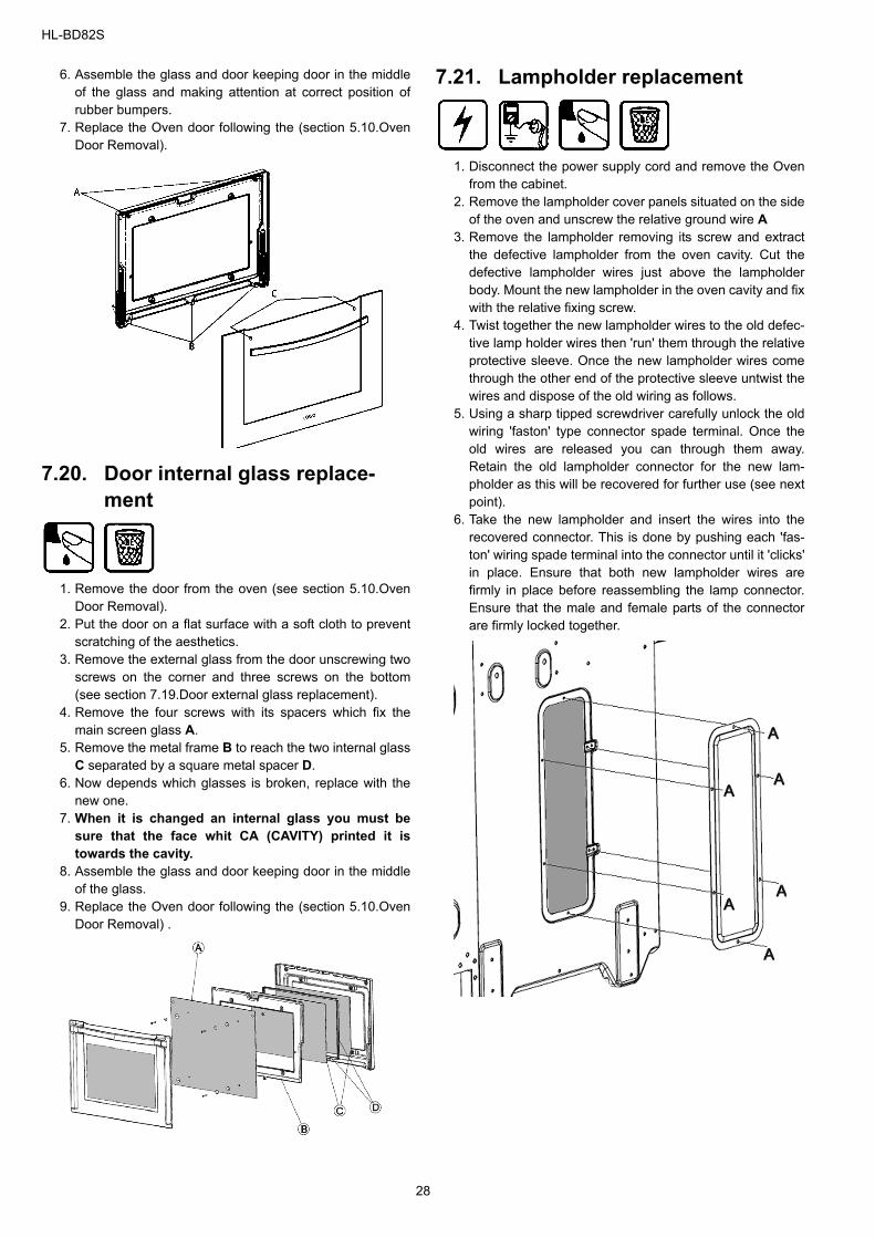
6. Assemble the glass and door keeping door in the middleof the glass and making attention at correct position ofrubber bumpers.
7. Replace the Oven door following the (section 5.10.OvenDoor Removal).
7.20. Door internal glass replace-ment
1. Remove the door from the oven (see section 5.10.OvenDoor Removal).
2. Put the door on a flat surface with a soft cloth to preventscratching of the aesthetics.
3. Remove the external glass from the door unscrewing twoscrews on the corner and three screws on the bottom(see section 7.19.Door external glass replacement).
4. Remove the four screws with its spacers which fix themain screen glass A.
5. Remove the metal frame B to reach the two internal glassC separated by a square metal spacer D.
6. Now depends which glasses is broken, replace with thenew one.
7. When it is changed an internal glass you must besure that the face whit CA (CAVITY) printed it istowards the cavity.
8. Assemble the glass and door keeping door in the middleof the glass.
9. Replace the Oven door following the (section 5.10.OvenDoor Removal) .
7.21. Lampholder replacement
1. Disconnect the power supply cord and remove the Ovenfrom the cabinet.
2. Remove the lampholder cover panels situated on the sideof the oven and unscrew the relative ground wire A
3. Remove the lampholder removing its screw and extractthe defective lampholder from the oven cavity. Cut thedefective lampholder wires just above the lampholderbody. Mount the new lampholder in the oven cavity and fixwith the relative fixing screw.
4. Twist together the new lampholder wires to the old defec-tive lamp holder wires then 'run' them through the relativeprotective sleeve. Once the new lampholder wires comethrough the other end of the protective sleeve untwist thewires and dispose of the old wiring as follows.
5. Using a sharp tipped screwdriver carefully unlock the oldwiring 'faston' type connector spade terminal. Once theold wires are released you can through them away.Retain the old lampholder connector for the new lam-pholder as this will be recovered for further use (see nextpoint).
6. Take the new lampholder and insert the wires into therecovered connector. This is done by pushing each 'fas-ton' wiring spade terminal into the connector until it 'clicks'in place. Ensure that both new lampholder wires arefirmly in place before reassembling the lamp connector.Ensure that the male and female parts of the connectorare firmly locked together.
28
HL-BD82S
7.22. Meat probe board replacement
1. Disconnect the power supply cord and remove the Ovenfrom the cabinet.
2. Remove the upper cover. 3. Remove the screws connecting the meat probe power
board. 4. Replace the new board using the spacers. 5. Connect the cable following the electric diagram. 6. IT IS VERY IMPORTANT TO CONNECT THE CABLES
IN THE RIGHT POSITION.7. The connections must not be loose. 8. Reconnect the power supply cord before installing the
Oven and check all functions. 9. Disconnect the power supply cord and reinstall the Oven
into the cabinet. 10. Reconnect the power supply cord after installing. 11. Run the Oven and check all functions.
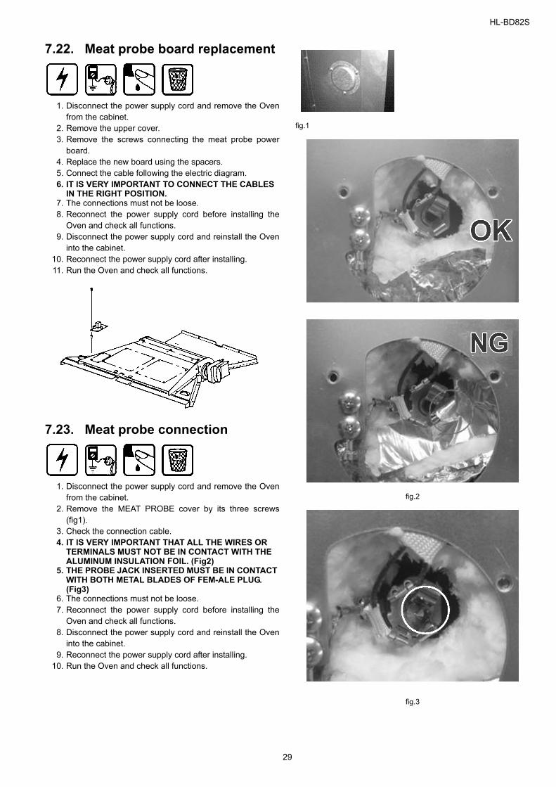
7.23. Meat probe connection
1. Disconnect the power supply cord and remove the Ovenfrom the cabinet.
2. Remove the MEAT PROBE cover by its three screws(fig1).
3. Check the connection cable. 4. IT IS VERY IMPORTANT THAT ALL THE WIRES OR
TERMINALS MUST NOT BE IN CONTACT WITH THE ALUMINUM INSULATION FOIL. (Fig2)
5. THE PROBE JACK INSERTED MUST BE IN CONTACT WITH BOTH METAL BLADES OF FEM-ALE PLUG. (Fig3)
6. The connections must not be loose. 7. Reconnect the power supply cord before installing the
Oven and check all functions. 8. Disconnect the power supply cord and reinstall the Oven
into the cabinet. 9. Reconnect the power supply cord after installing.
10. Run the Oven and check all functions.
fig.1
fig.2
fig.3
29
HL-BD82S
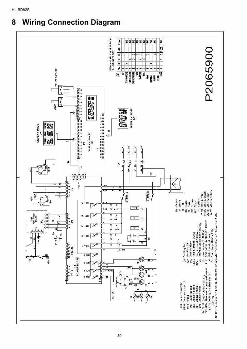
8 Wiring Connection Diagram
30
HL-BD82S
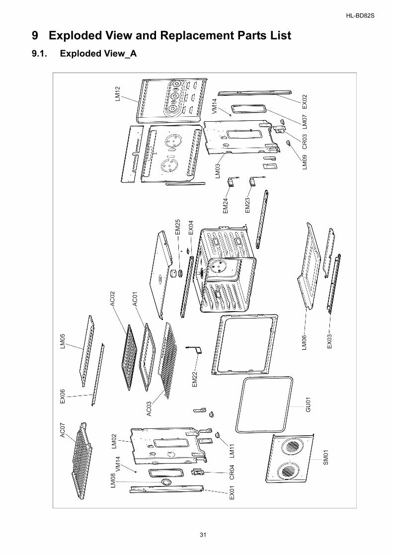
9 Exploded View and Replacement Parts List9.1. Exploded View_A
31
HL-BD82S
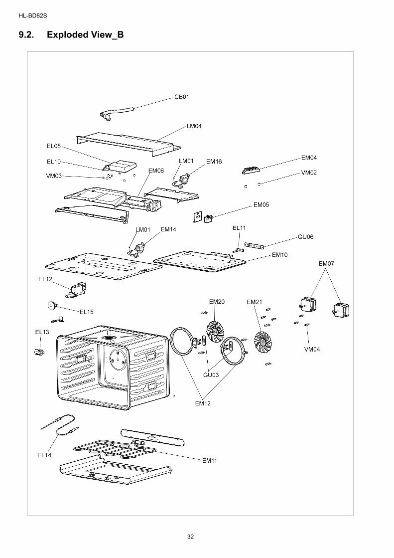
9.2. Exploded View_B
32
HL-BD82S
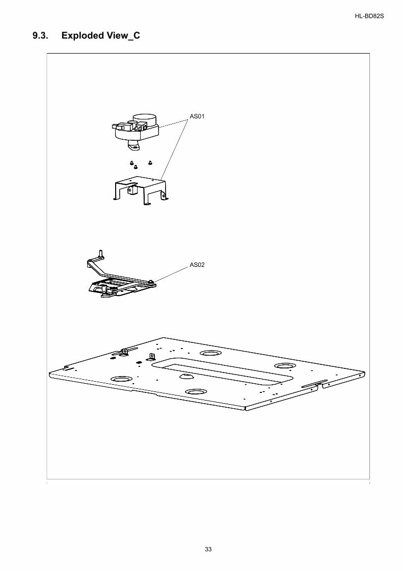
9.3. Exploded View_C
33
HL-BD82S
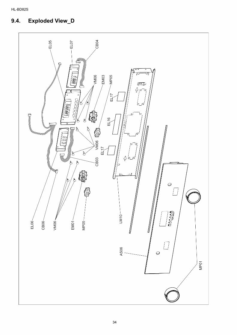
9.4. Exploded View_D
34
HL-BD82S
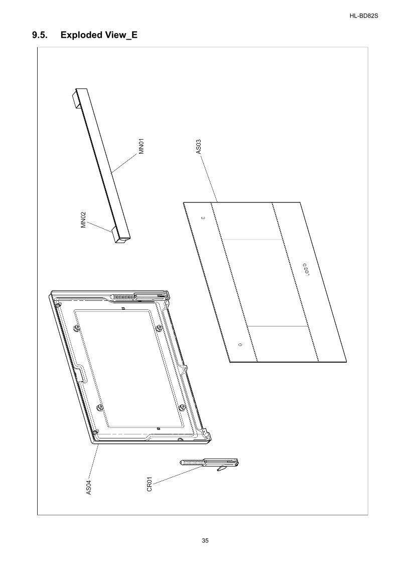
9.5. Exploded View_E
35
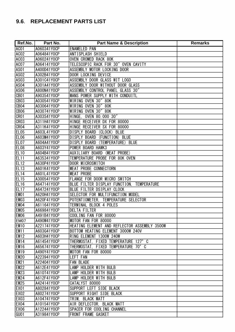
9.6. REPLACEMENT PARTS LIST
Ref.No. Part No. Part Name & Description Remarks AC01 A060341Y0CP ENAMELED PAN AC02 A064841Y0CP ANTISPLASH SHIELD AC03 A060241Y0CP OVEN CROMED RACK 80K AC07 A064141Y0CP TELESCOPIC RACK FOR 30" OVEN CAVITY AS01 A400D41Y0CP ASSEMBLY MOTOR LOCKING DOOR AS02 A302B41Y0CP DOOR LOCKING DEVICE AS03 A301C41Y0CP ASSEMBLY DOOR GLASS WIT LOGO AS04 A301A41Y0CP ASSEMBLY DOOR WITHOUT DOOR GLASS AS06 A800N41Y0CP ASSEMBLY CONTROL PANEL GLASS 30" CB01 A903541Y0CP MANS POWER SUPPLY WITH CONDUITL CB03 A030541Y0CP WIRING OVEN 30" 80K CB04 A030641Y0CP WIRING OVEN 30" 80K CB06 A030741Y0CP WIRING OVEN 30" 80K CR01 A303S41Y0CP HINGE, OVEN 80.000 30" CR03 A311H41Y0CP HINGE RECEIVER DX FOR 80000 CR04 A311K41Y0CP HINGE RECEIVER SX FOR 80000 EL05 A603L41Y0CP DISPLY BOARD (CLOCK) BLUE EL06 A603M41Y0CP DISPLY BOARD (FUNCTION) BLUE EL07 A604A41Y0CP DISPLY BOARD (TEMPERATURE) BLUE EL08 A603Y41Y0CP POWER BOARD HAWK3 EL10 A604B41Y0CP AUXILIARY BOARD (MEAT PROBE) EL11 A635341Y0CP TEMPERATURE PROBE FOR 80K OVEN EL12 A630P41Y0CP DOOR MICROSWITCH EL13 A601K41Y0CP MEAT PROBE CONNECTORN EL14 A601L41Y0CP MEAT PROBE EL15 A300541Y0CP FLANGE FOR DOOR MICRO SWITCH EL16 A647141Y0CP BLUE FILTER DISPLAY FUNCTION, TEMPERATURE EL17 A647241Y0CP BLUE FILTER DSIPLAY CLOCK EM01 A620H41Y0CP SELECTOR FOR MULTIFUNCTION MODEL EM03 A620F41Y0CP POTENTIOMETER, TEMPERATURE SELECTOR EM04 A611641Y0CP TERMINAL BLOCK 4 POLES EM05 A669841Y0CP DELTA FILTER EM06 A491B41Y0CP COOLING FAN FOR 80000 EM07 A490W41Y0CP MOTOR FAN FOR 80000 EM10 A221741Y0CP HEATING ELEMENT AND REFLECTOR ASSEMBLY 3500W EM11 A603G41Y0CP BOTTOM HEATING ELEMENT 3000W 240V EM12 A603H41Y0CP RING ELEMENT 1300W 240W EM14 A614541Y0CP THERMOSTAT, FIXED TEMPERATURE 127°C EM16 A656741Y0CP THERMOSTAT, FIXED TEMPERATURE 70°C EM19 A490Y41Y0CP MOTOR FAN FOR 80000 EM20 A223941Y0CP LEFT FAN EM21 A224041Y0CP FAN BLADE EM22 A612E41Y0CP LAMP HOLDER WITH BULB EM23 A610T41Y0CP LAMP HOLDER WITH BULB EM24 A612F41Y0CP LAMP HOLDER WITH BULB EM25 A424141Y0CP CATALYST 80000 EX01 A802841Y0CP SUPPORT LEFT SIDE BLACK EX02 A802741Y0CP SUPPORT RIGHT SIDE BLACK EX03 A104741Y0CP TRIM, BLACK MATT EX04 A101541Y0CP AIR DEFLECTOR, BLACK MATT EX06 A122441Y0CP SPACER FOR COOLING CHANNEL GU01 A319841Y0CP FRONT FRAME GASKET
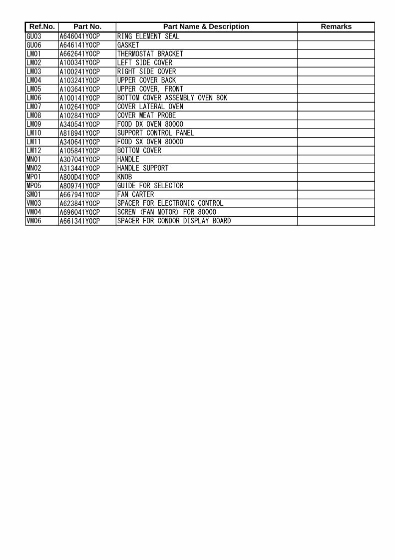
Ref.No. Part No. Part Name & Description Remarks GU03 A646041Y0CP RING ELEMENT SEAL GU06 A646141Y0CP GASKET LM01 A662641Y0CP THERMOSTAT BRACKET LM02 A100341Y0CP LEFT SIDE COVER LM03 A100241Y0CP RIGHT SIDE COVER LM04 A103241Y0CP UPPER COVER BACK LM05 A103641Y0CP UPPER COVER, FRONT LM06 A100141Y0CP BOTTOM COVER ASSEMBLY OVEN 80K LM07 A102641Y0CP COVER LATERAL OVEN LM08 A102841Y0CP COVER MEAT PROBE LM09 A340541Y0CP FOOD DX OVEN 80000 LM10 A818941Y0CP SUPPORT CONTROL PANEL LM11 A340641Y0CP FOOD SX OVEN 80000 LM12 A105841Y0CP BOTTOM COVER MN01 A307041Y0CP HANDLE MN02 A313441Y0CP HANDLE SUPPORT MP01 A800D41Y0CP KNOB MP05 A809741Y0CP GUIDE FOR SELECTOR SM01 A667941Y0CP FAN CARTER VM03 A623841Y0CP SPACER FOR ELECTRONIC CONTROL VM04 A696041Y0CP SCREW (FAN MOTOR) FOR 80000 VM06 A661341Y0CP SPACER FOR CONDOR DISPLAY BOARD