Embed Size (px)
Citation preview
Campaign for Levitation in LDX
D.T. Garnier, M.E. Mauel, A.K. Hansen, E.E. Ortiz
Columbia University
A. Boxer, J. Ellsworth, I. Karim, J. Kesner, P. Michael, A. Radovinsky, A. Zhukovsky,
R. Bergmann - MIT PSFC
Columbia University

Synopsis
Levitation will greatly change plasma behavior in LDX
Dominant loss channel removed -> better confinement
Higher background density with high beta -> more stable to HEI
Radial transport dominated (broader) profile -> more stable
Levitation system nearly complete
Coil and control systems installation complete
Calibration and control algorithm development underway
Laser detection system nearly complete and undergoing refinement
Catcher system built and tested
Levitation system testing in progress
3 major tests completed give confidence in successful levitation
Integration of L-coil systems
Development of Realtime control system
Test of L-coil electrical and thermal performance
Development of Laser Detection System
Plasma "Noise" test
Launcher Catcher Upgrade
Catcher Test Campaign
Feedback Control Algorithm
Flight Tests
Levitation Campaign Milestones
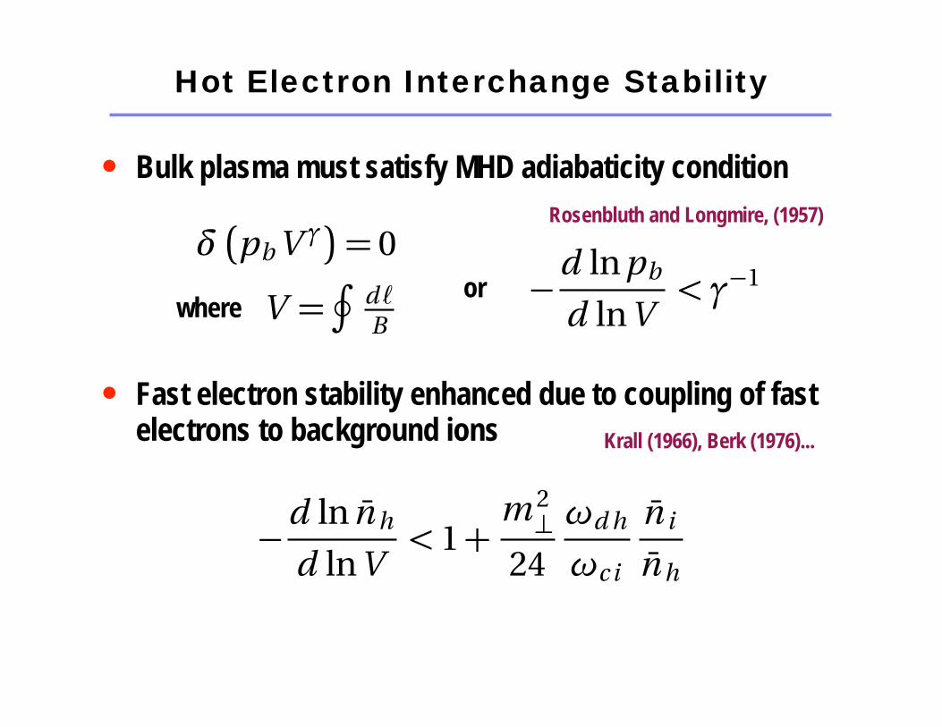
Bulk plasma must satisfy MHD adiabaticity condition
Fast electron stability enhanced due to coupling of fast electrons to background ions
Hot Electron Interchange Stability
Krall (1966), Berk (1976)...
Rosenbluth and Longmire, (1957)
δ�
pb V γ�= 0
−
d ln pb
d ln V<γ−1
V =∮
d �B
whereor
−
d ln n̄ h
d ln V< 1+
m 2⊥
24
ωd h
ωc i
n̄ i
n̄ h
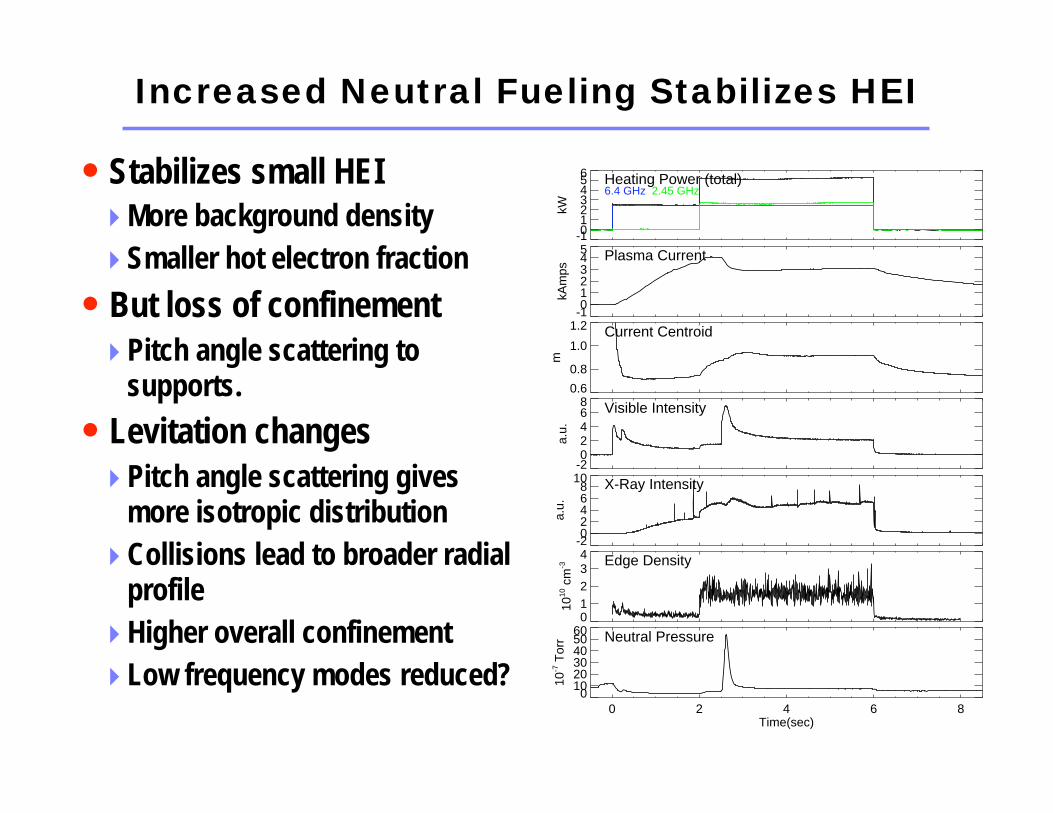
Increased Neutral Fueling Stabilizes HEI
Stabilizes small HEI
More background density
Smaller hot electron fraction
But loss of confinement
Pitch angle scattering to supports.
Levitation changes
Pitch angle scattering gives more isotropic distribution
Collisions lead to broader radial profile
Higher overall confinement
Low frequency modes reduced?
-10123456
kW
Heating Power (total)6.4 GHz 2.45 GHz
-1012345
kAm
ps
Plasma Current
0.6
0.8
1.0
1.2
m
Current Centroid
-202468
a.u.
Visible Intensity
-202468
10
a.u.
X-Ray Intensity
01234
1010
cm
-3 Edge Density
0 2 4 6 8Time(sec)
0102030405060
10-7 T
orr Neutral Pressure

LDX Levitation Basics
2 m
Levitation by upper lift magnet
Unstable only to vertical motion
Mostly undamped stable secondary modes
HTS lift magnet
First in US Fusion program
Much reduced power and cooling requirements
AC heating introduces unique requirements for control system
Large 5 m diameter vacuum vessel
Eddy current times << levitation times
Laser position detection
Many secondary diagnostics
Digital feedback system
L-coil
F-coil

L-Coil Design
High Temperature Superconductor.
Negligibly power consumption compared to resistive equivalent.
Nominal 105 A current, with ± 1 A, 1 Hz position control ripple.
Easier to manage position control ac loss than for LTS.
Funded by SBIR, first HTS coil in US fusion energy program.
Optimized, disk-shape geometry for F-coil levitation.
Double pancake winding.
Center support and cooling plate.
Conduction cooled coil.
Low maintenance, moderate cost,
high conductor performance.
Estimated 12 W hysteresis loss.
One-stage cryocooler for coil.
20W @ 20K
Liquid nitrogen reservoir
for radiation shield.

L-coil Heating Stress Test
Steady State Test
90-min, 1Hz, ±1-A ripple with 105-Adc bias test performed on Apr. 5, 2006
Demonstrates the thermal stability of HTS coil in expected levitation operation
Well below theoretical quench point
at ~40 K
Sub-cooling demonstrated
Evacuation of LN2 reservoir to 500 Torr.
Gives greater operational margin at warm end of HTS leads

L-coil Heating Model
Semi-empirical model estimates the steady-state temperature rise at the L-coil during electrical excitation
over the range from 0-A dc to 105-A dc bias current
ac excitation at frequency from -Hz to 2-Hz
AC ripple 0-Vac and 20-Vac.
accurate to within approximately 0.2-K over the entire fitting range.
17.0
17.5
18.0
18.5
19.0
19.5
20.0
20.5
0 0.5 1 1.5 2 2.5
Frequency [Hz]
Te
mp
era
ture
[K
]
CR, meas. 50Adc bias
UP, meas, 50Adc bias
LP, meas. 50Adc bias
CR, fit 50Adc bias
UP, fit 50Adc bias
LP, fit 50Adc bias
CR, meas. 95Adc bias
UP, meas. 95Adc bias
LP, meas. 95Adc bias
CR, fit 95Adc bias
UP, fit 95Adc bias
LP, fit 95Adc bias
17.0
17.5
18.0
18.5
19.0
19.5
20.0
20.5
0 5 10 15 20 25
1 Hz, AC voltage [V]
Tem
pera
ture
[K
]CR, meas. 50Adc bias
UP, meas. 50Adc bias
LP, meas. 50Adc bias
CR, fit 50Adc bias
UP, fit 50Adc bias
LP, fit 50Adc bias
CR, meas. 105Adc bias
UP, meas. 105Adc bias
LP, meas. 105Adc bias
CR, fit 105Adc bias
UP, fit 105Adc bias
LP, fit 105Adc bias
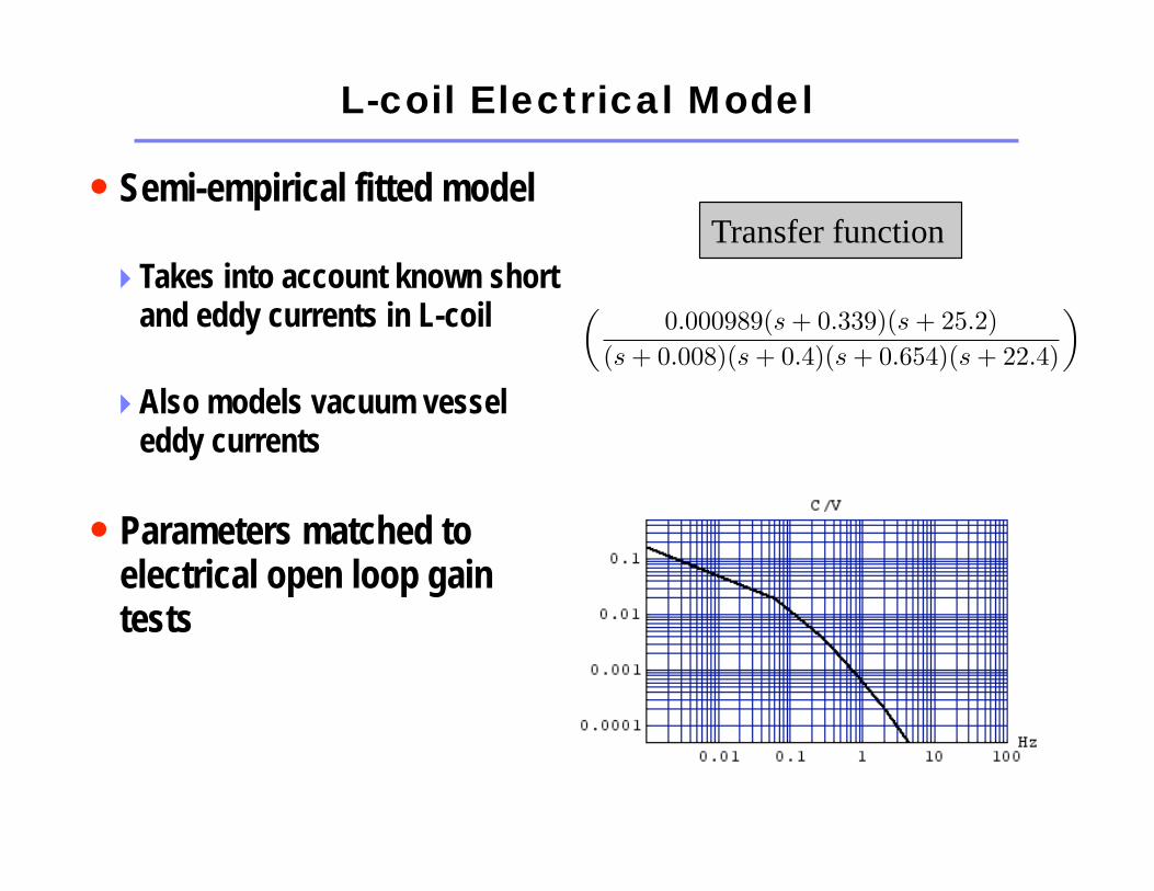
L-coil Electrical Model
Semi-empirical fitted model
Takes into account known short and eddy currents in L-coil
Also models vacuum vessel eddy currents
Parameters matched to electrical open loop gain tests
(0.000989(s + 0.339)(s + 25.2)
(s + 0.008)(s + 0.4)(s + 0.654)(s + 22.4)
)Transfer function
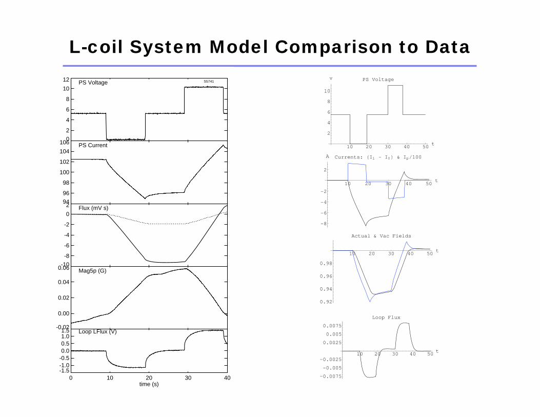
L-coil System Model Comparison to Data
10 20 30 40 50t
2
4
6
8
10
v PS Voltage
10 20 30 40 50t
-8
-6
-4
-2
2
A Currents: �Il � I0� & Ip�100
10 20 30 40 50t
0.92
0.94
0.96
0.98
Actual & Vac Fields
10 20 30 40 50t
-0.0075
-0.005
-0.0025
0.0025
0.005
0.0075
Loop Flux
0
2
4
6
8
10
12 PS Voltage S5741
94
96
98
100
102
104
106 PS Current
-10
-8
-6
-4
-2
0
2 Flux (mV s)
-0.02
0.00
0.02
0.04
0.06 Mag5p (G)
0 10 20 30 40time (s)
-1.5-1.0-0.50.00.51.01.5 Loop LFlux (V)
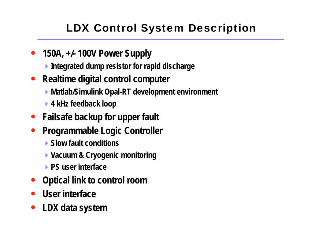
LDX Control System Description
150A, +/- 100V Power Supply
Integrated dump resistor for rapid discharge
Realtime digital control computer
Matlab/Simulink Opal-RT development environment
4 kHz feedback loop
Failsafe backup for upper fault
Programmable Logic Controller
Slow fault conditions
Vacuum & Cryogenic monitoring
PS user interface
Optical link to control room
User interface
LDX data system
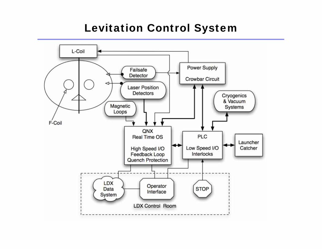
Levitation Control System
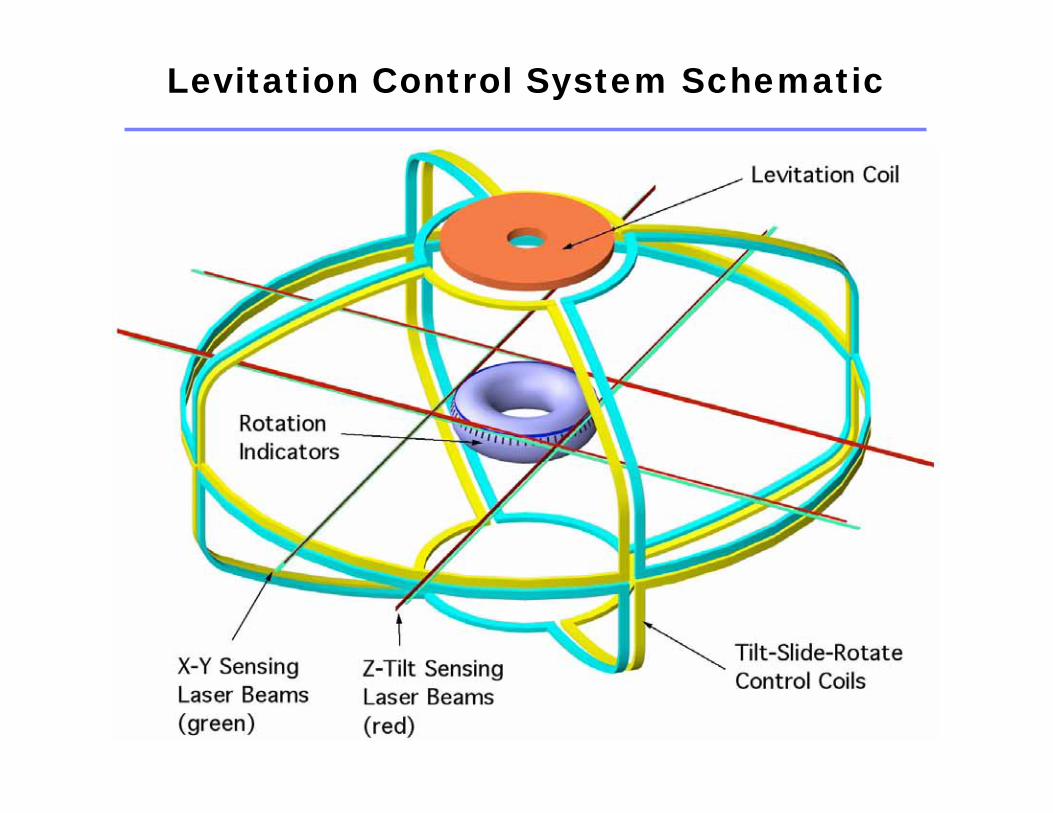
Levitation Control System Schematic
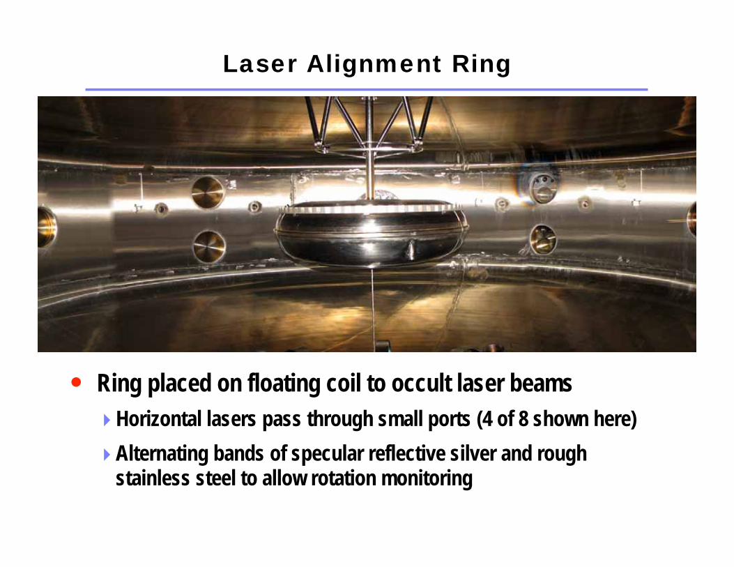
Laser Alignment Ring
Ring placed on floating coil to occult laser beams
Horizontal lasers pass through small ports (4 of 8 shown here)
Alternating bands of specular reflective silver and rough stainless steel to allow rotation monitoring
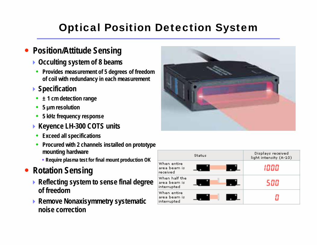
Optical Position Detection System
Position/Attitude Sensing
Occulting system of 8 beams
Provides measurement of 5 degrees of freedom
of coil with redundancy in each measurement
Specification
± 1 cm detection range
5 m resolution
5 kHz frequency response
Keyence LH-300 COTS units
Exceed all specifications
Procured with 2 channels installed on prototype
mounting hardware
• Require plasma test for final mount production OK
Rotation Sensing
Reflecting system to sense final degree of freedom
Remove Nonaxisymmetry systematic noise correction

Laser Position Detector Testing
Prototype mounting and amplifiers in place for July 2006 plasma run
RF electrical pickup noise measured
Plasma light not important
Vibration somewhat important
Measured motion of F-coil on stiff spring of fixed launcher
Further development since
Better vibration immunity (higher frequency)
Reduced electrical noise
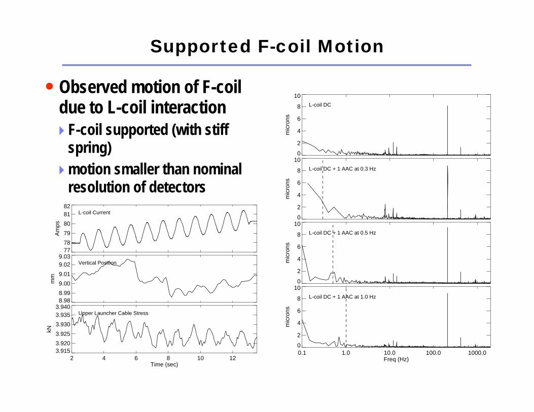
Supported F-coil Motion
Observed motion of F-coil due to L-coil interaction
F-coil supported (with stiff spring)
motion smaller than nominal resolution of detectors
0
2
4
6
8
10
mic
rons
L-coil DC
0
2
4
6
8
10
mic
rons
L-coil DC + 1 AAC at 0.3 Hz
0
2
4
6
8
10
mic
rons
L-coil DC + 1 AAC at 0.5 Hz
0.1 1.0 10.0 100.0 1000.0Freq (Hz)
0
2
4
6
8
10m
icro
ns
L-coil DC + 1 AAC at 1.0 Hz
7778
79
80
8182
Am
ps
L-coil Current
8.988.99
9.00
9.01
9.029.03
mm
Vertical Position
2 4 6 8 10 12Time (sec)
3.9153.920
3.925
3.930
3.9353.940
kN
Upper Launcher Cable Stress
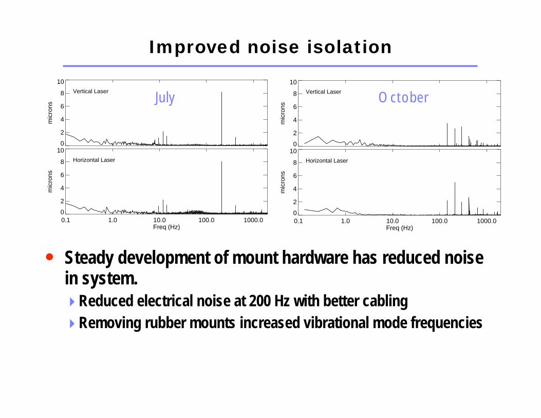
Improved noise isolation
Steady development of mount hardware has reduced noise in system.
Reduced electrical noise at 200 Hz with better cabling
Removing rubber mounts increased vibrational mode frequencies
0
2
4
6
8
10
mic
rons
Vertical Laser
0.1 1.0 10.0 100.0 1000.0Freq (Hz)
0
2
4
6
8
10
mic
rons
Horizontal Laser
0
2
4
6
8
10
mic
rons
Vertical Laser
0.1 1.0 10.0 100.0 1000.0Freq (Hz)
0
2
4
6
8
10
mic
rons
Horizontal Laser
July October

Upper Catcher / Space frame
Upper catcher
Limit upward motion
Align radial motion for fall to catcher
Space frame structure
Allows installation of new internal magnetic flux loops near plasma
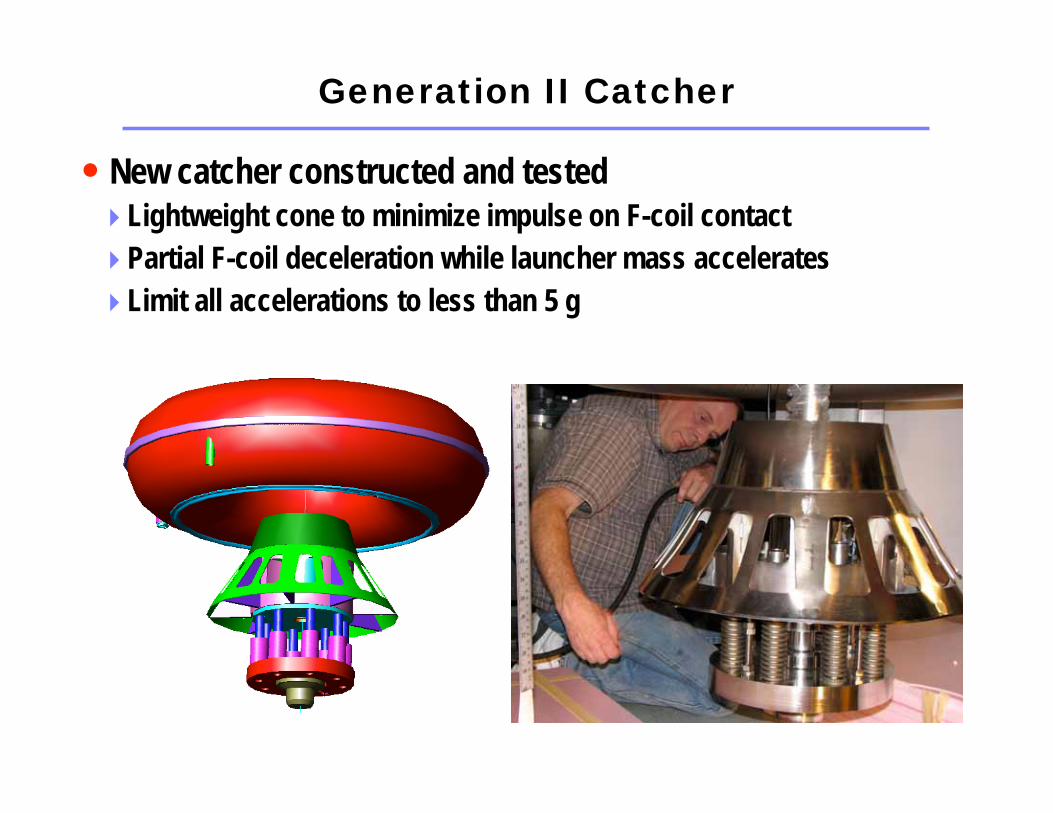
Generation II Catcher
New catcher constructed and tested
Lightweight cone to minimize impulse on F-coil contact
Partial F-coil deceleration while launcher mass accelerates
Limit all accelerations to less than 5 g
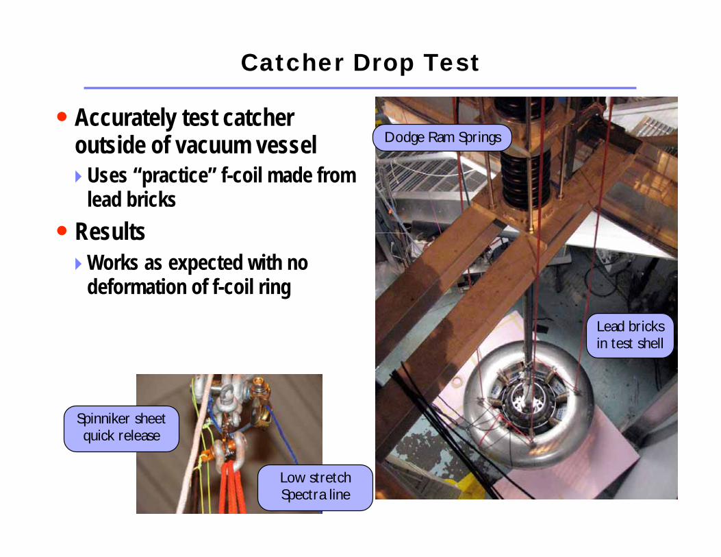
Catcher Drop Test
Accurately test catcher outside of vacuum vessel
Uses “practice” f-coil made from lead bricks
Results
Works as expected with no deformation of f-coil ring
Dodge Ram Springs
Lead bricks in test shell
Spinniker sheet quick release
Low stretch Spectra line

Free flight
Catcher Worst Case ~ 5g
-10
-505
10
(g)
F-coil Acceleration
-10
-505
10
(g)
Catcher Acceleration
0.8 1.0 1.2 1.4 1.6 1.8 2.0 2.2Time (sec)
-10-505
10
(g)
Post Acceleration
Free flight after bounce
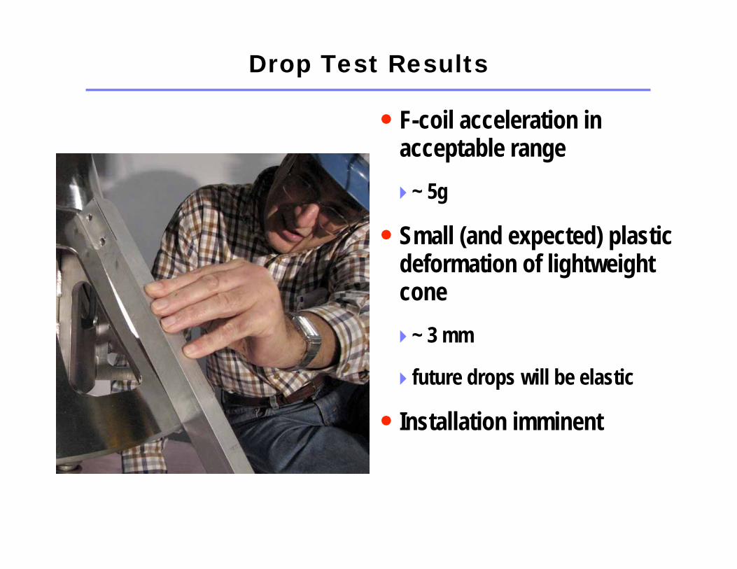
Drop Test Results
F-coil acceleration in acceptable range
~ 5g
Small (and expected) plastic deformation of lightweight cone
~ 3 mm
future drops will be elastic
Installation imminent
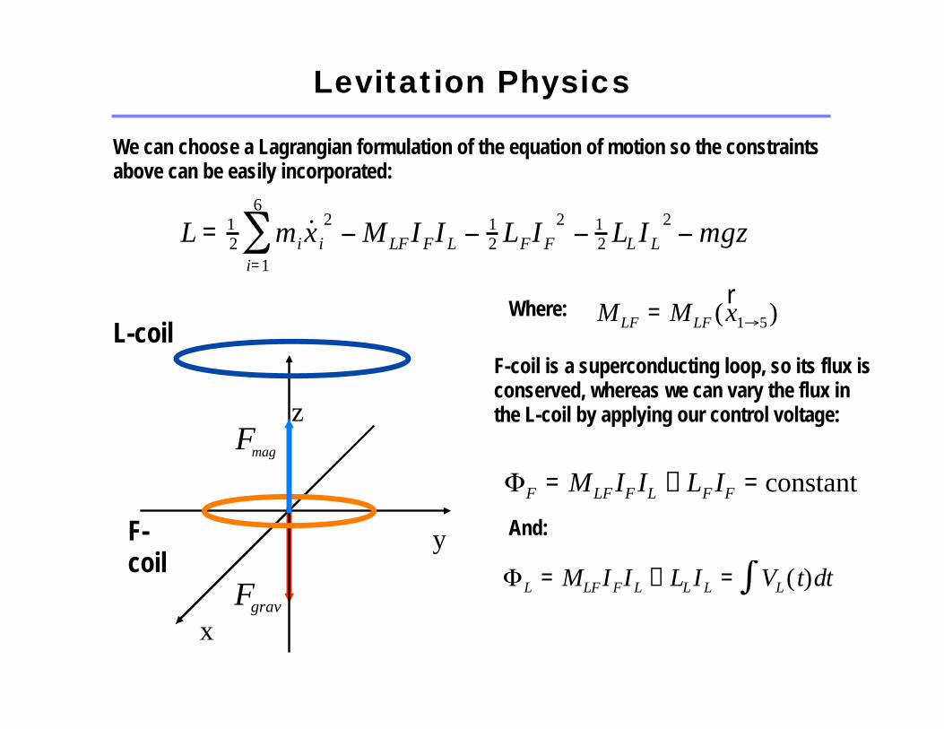
Levitation Physics
x
y
z
L-coil
F-coil
Fgrav
Fmag
We can choose a Lagrangian formulation of the equation of motion so the constraints above can be easily incorporated:
L = 12 mi
˙ x i2
i=1
6
MLFIFIL12 LFIF
2 12 LLIL
2mgz
F-coil is a superconducting loop, so its flux is conserved, whereas we can vary the flux in the L-coil by applying our control voltage:
F = MLFIFIL + LFIF = constant
L = MLFIFIL + LLIL = VL( t)dt
MLF = MLF (r x 1 5)Where:
And:
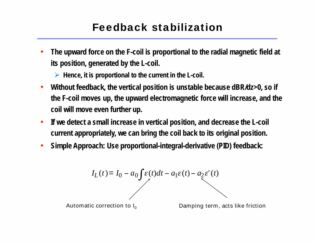
Feedback stabilization
IL (t )= I0 a0 (t)dt a1 (t) a2 ' (t)
Automatic correction to I0 Damping term, acts like friction
The upward force on the F-coil is proportional to the radial magnetic field at
its position, generated by the L-coil.
Hence, it is proportional to the current in the L-coil.
Without feedback, the vertical position is unstable because dBR/dz>0, so if
the F-coil moves up, the upward electromagnetic force will increase, and the
coil will move even further up.
If we detect a small increase in vertical position, and decrease the L-coil
current appropriately, we can bring the coil back to its original position.
Simple Approach: Use proportional-integral-derivative (PID) feedback:
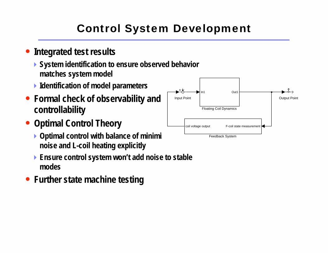
Control System Development
Integrated test results
System identification to ensure observed behavior
matches system model
Identification of model parameters
Formal check of observability and controllability
Optimal Control Theory
Optimal control with balance of minimization of
noise and L-coil heating explicitly
Ensure control system won’t add noise to stable
modes
Further state machine testing
Output PointInput Point
In1 Out1
Floating Coil Dynamics
F-coil state measurementcoil voltage output
Feedback System
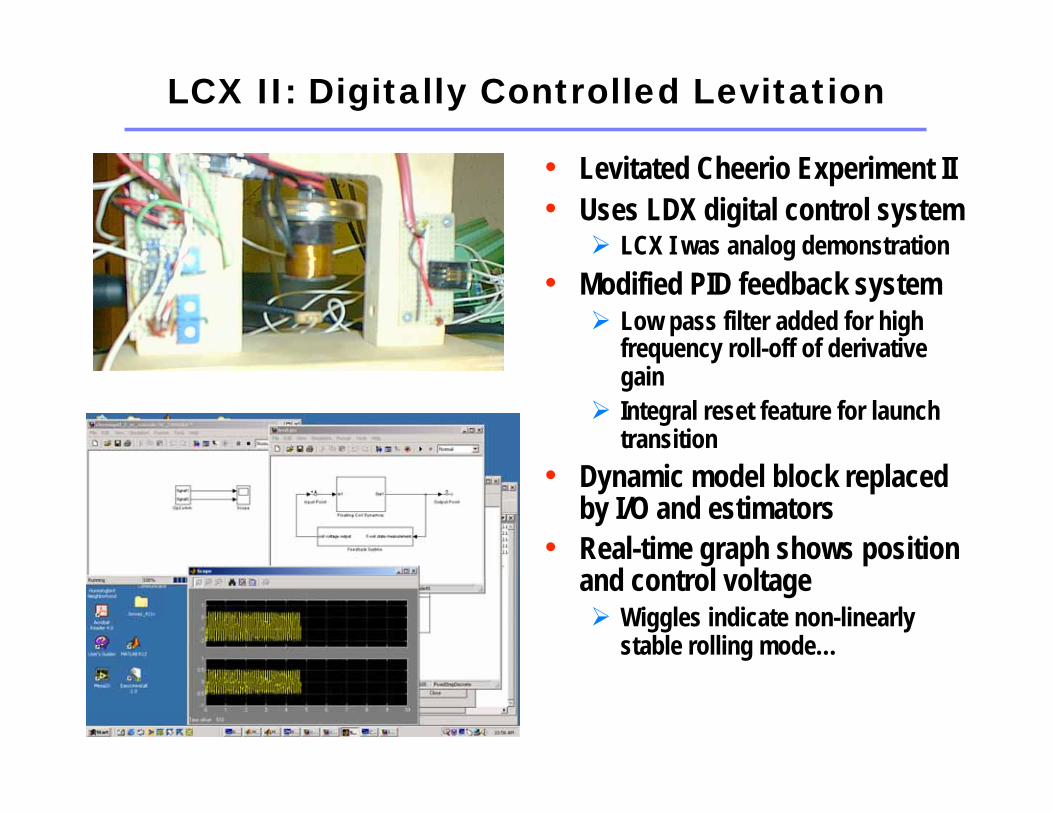
LCX II: Digitally Controlled Levitation
Levitated Cheerio Experiment II
Uses LDX digital control systemLCX I was analog demonstration
Modified PID feedback systemLow pass filter added for high frequency roll-off of derivative gain
Integral reset feature for launch transition
Dynamic model block replaced by I/O and estimators
Real-time graph shows position and control voltage
Wiggles indicate non-linearly stable rolling mode…
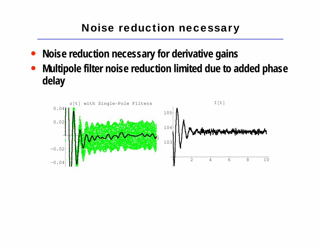
Noise reduction necessary
Noise reduction necessary for derivative gains
Multipole filter noise reduction limited due to added phase delay
2 4 6 8 10
-0.04
-0.02
0.02
0.04z�t� with Single�Pole Filters
2 4 6 8 10
103
104
105
I�t�

Kalman Filter Simulation
Kalman filter can be used to reduce noise with minimal latency
Uses a physics based predictor that tracks the real motion and is updated with every time step
2 4 6 8 10
-0.1
0.1
0.2
0.3
0.4
Actual F�Coil z�t�
2 4 6 8 10
-0.1
0.1
0.2
0.3
0.4
Meas & State F�Coil z
2 4 6 8 10
-15
-10
-5
Volt�t�
2 4 6 8 10
103.2
103.4
103.6
103.8
L�Coil Current
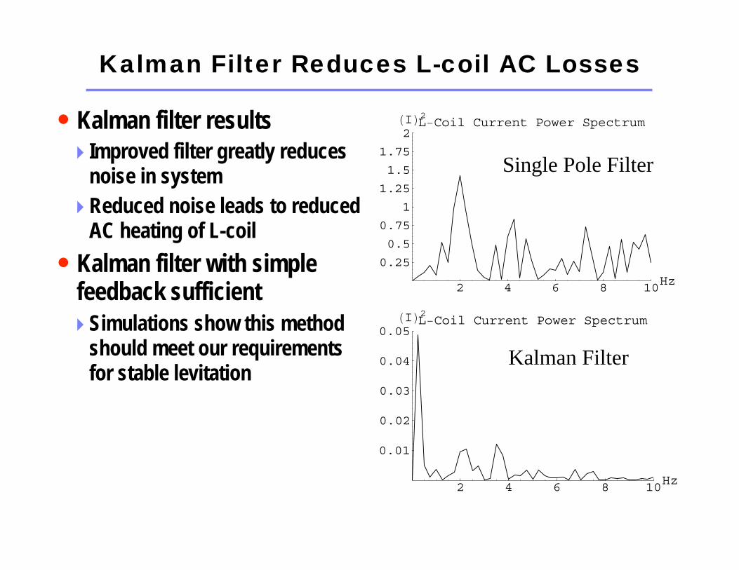
Kalman Filter Reduces L-coil AC Losses
Kalman filter results
Improved filter greatly reduces noise in system
Reduced noise leads to reduced AC heating of L-coil
Kalman filter with simple feedback sufficient
Simulations show this method should meet our requirements for stable levitation
2 4 6 8 10Hz
0.01
0.02
0.03
0.04
0.05�I�2L�Coil Current Power Spectrum
2 4 6 8 10Hz
0.25
0.5
0.75
1
1.25
1.5
1.75
2�I�2L�Coil Current Power Spectrum
Single Pole Filter
Kalman Filter

2006 Levitation Test Program
System integration test
Test inter-operation of cryogenic and two control systems
L-coil Integrated Performance Test
Test L-coil cryogenic performance under worst-case operation point
Also gather data to determine HTS coil quench detection algorithm
Calibrate “transfer function” of L-coil System
Integrated System Plasma Test
Characterize noise on levitation diagnostics in plasma environment
Operate L-coil systems at 1/2 current with plasma present
Calibrate system using measured lift forces
Catcher Drop Test
Operated successfully from worst-case scenario
Measured acceleration in acceptable range
Levitation Test Next
Alternative Levitation System
Greatly simplified
Reduced cost
Easily manufactured
numerous local vendors: Starbucks, Dunkin’ Donuts, etc.
Implementation likely to be “challenging”


![LDX - SmartAVI · 2020. 3. 12. · LDX-S DVI-D and RS-232 Extender. Includes: [LDX-TX, LDX-RX, 2x (PS5VDC2A)] technical specifications Tel: (800) AVI-2131 (702) 800-0005 2455 W Cheyenne](https://img.pdfslide.us/doc/110x75/6124010409081f35aa51fcd4/ldx-smartavi-2020-3-12-ldx-s-dvi-d-and-rs-232-extender-includes-ldx-tx.jpg)