Embed Size (px)
DESCRIPTION
Image Processing. Introduction to Image Processing. Cameras, lenses and sensors. Cosimo Distante [email protected] [email protected]. Cameras, lenses and sensors. Camera Models Pinhole Perspective Projection Camera with Lenses Sensing The Human Eye. - PowerPoint PPT Presentation
Citation preview

ComputerVision
Cameras, lenses and sensors
Cosimo Distante
[email protected]@unisalento.it
Introduction to Image Processing
Image Processing

Image Processing
• Camera Models– Pinhole Perspective Projection
• Camera with Lenses• Sensing• The Human Eye
Cameras, lenses and sensors

Image Processing
Images are two-dimensional patterns of brightness values.
They are formed by the projection of 3D objects.
Figure from US Navy Manual of Basic Optics and Optical Instruments, prepared by Bureau of Naval Personnel. Reprinted by Dover Publications, Inc., 1969.

Image Processing
Animal eye:
a looonnng time ago.
Pinhole perspective projection: Brunelleschi, XVth Century.Camera obscura: XVIth Century.
Photographic camera:Niepce, 1816.

Image Processing Pinhole model

Image Processing Distant objects appear smaller

Image Processing Parallel lines meet
• vanishing point

Image Processing Vanishing points
VPL VPRH
VP1VP2
VP3
To different directions correspond different vanishing points

Image Processing Geometric properties of projection
• Points go to points• Lines go to lines• Planes go to whole image
or half-plane• Polygons go to polygons
• Degenerate cases:– line through focal point yields point– plane through focal point yields line

Image Processing Pinhole Camera Model
Image planeImage plane
Optical axisOptical axis
XX
OO ff
P=(X,Z)P=(X,Z)
Z
X
f
x
Z
Xfx
P=(x,f)P=(x,f) XXxx
ZZ

Image Processing Pinhole Camera Model
Image planeImage plane
Optical axisOptical axis
YY
OO ff
P=(Y,Z)P=(Y,Z)
Z
Y
f
y
Z
Yfy
P=(y,f)P=(y,f) YYyy
ZZ

Image Processing
Pinhole Perspective Equation
z
yfy
z
xfx
''
''
Focal length
Camera frame Scene /
world points
Optical axis
Image plane

Image Processing
Affine projection models: Weak perspective projection
0
'where'
'z
fmmyy
mxx
is the magnification.
When the scene relief is small compared its distance from theCamera, m can be taken constant: weak perspective projection.

Image Processing
Affine projection models: Orthographic projection
yy
xx
'
' When the camera is at a(roughly constant) distancefrom the scene, take m=1.

Image Processing
Planar pinhole perspective
Orthographicprojection
Spherical pinholeperspective

Image Processing Limits for pinhole cameras

Image Processing Limits for pinhole cameras

Image Processing Camera obscura + lens

Image Processing
Lenses
Snell’s law
n1 sin 1 = n2 sin 2
Descartes’ law

Image Processing
Field of view

Parameters of an optical system
Two parameters characterize an optical system•focal lenght ffocal lenght f •Diameter DDiameter D that determines the amount of light hitting the image plane
focal point
F
optical center(Center Of Projection)

Parameters of an optical systemRelative ApertureRelative Aperture is the ratio D/f Its inverse is named diaphragm aperture a, defined as:
a = f/D f/#
The diaphragm is a mechanism to limit the amount of light throug the optical system and reaching the imag plane where photosensors are deposited (i.e CCD sensor)
The diaphragm is composed of many lamellae hinged on a ring which rotate in a synchronized manner by varying the size of the circular opening, thus limiting the passage of light
Diaphragm F

Parameters of an optical system
Aperture scale varies with square of first value is 1 Other values are 1.4, 2, 2.8, 4, 5.6, 8, 11, 16, 32, 45, 60, …
Normally an optical system is dinamically configured to project the right amount of light, by compensating with the exposure time
2

Parameters of an optical system
35mm set at f/11, Aperture varies from f/2.0 to f/22

Parameters of an optical system

Lens field of view computation
Lens choise depend on the wanted acquired scene.
Per le telecamere con CCD 1/4”
Focal lenght (mm) = Target distance (m.) x 3,6 : width (m.)
Per tutte le altre telecamere con CCD 1/3"Focal lenght (mm) = Target distance (m.) x 4,8 : width (m.)

Focus and depth of field
Changing the aperture size affects depth of field• A smaller aperture increases the range in which the object is
approximately in focus
f / 5.6
f / 32
Flower images from Wikipedia http://en.wikipedia.org/wiki/Depth_of_field

Depth from focus
[figs from H. Jin and P. Favaro, 2002]
Images from same point of view, different camera parameters
3d shape / depth estimates

Field of view
• Angular measure of portion of 3d space seen by the camera
Images from http://en.wikipedia.org/wiki/Angle_of_view K. Grauman

• As f gets smaller, image becomes more wide angle – more world points project
onto the finite image plane
• As f gets larger, image becomes more telescopic – smaller part of the world
projects onto the finite image plane
Field of view depends on focal length
from R. Duraiswami

Field of view depends on focal length
Smaller FOV = larger Focal LengthSlide by A. Efros

Vignetting
http://www.ptgui.com/examples/vigntutorial.htmlhttp://www.tlucretius.net/Photo/eHolga.html

Vignetting
• “natural”:
• “mechanical”: intrusion on optical path

Chromatic aberration

Chromatic aberration

Image Processing Deviations from the lens model
3 assumptions :
1. all rays from a point are focused onto 1 image point
2. all image points in a single plane
3. magnification is constant
deviations from this ideal are aberrations

Image Processing Aberrations
chromatic : refractive index function of wavelength
2 types :
1. geometrical
2. chromatic
geometrical : small for paraxial rays
study through 3rd order optics

Image Processing Geometrical aberrations
spherical aberration
astigmatism
distortion
coma
aberrations are reduced by combining lenses

Image Processing Spherical aberration
rays parallel to the axis do not converge
outer portions of the lens yield smaller focal lenghts
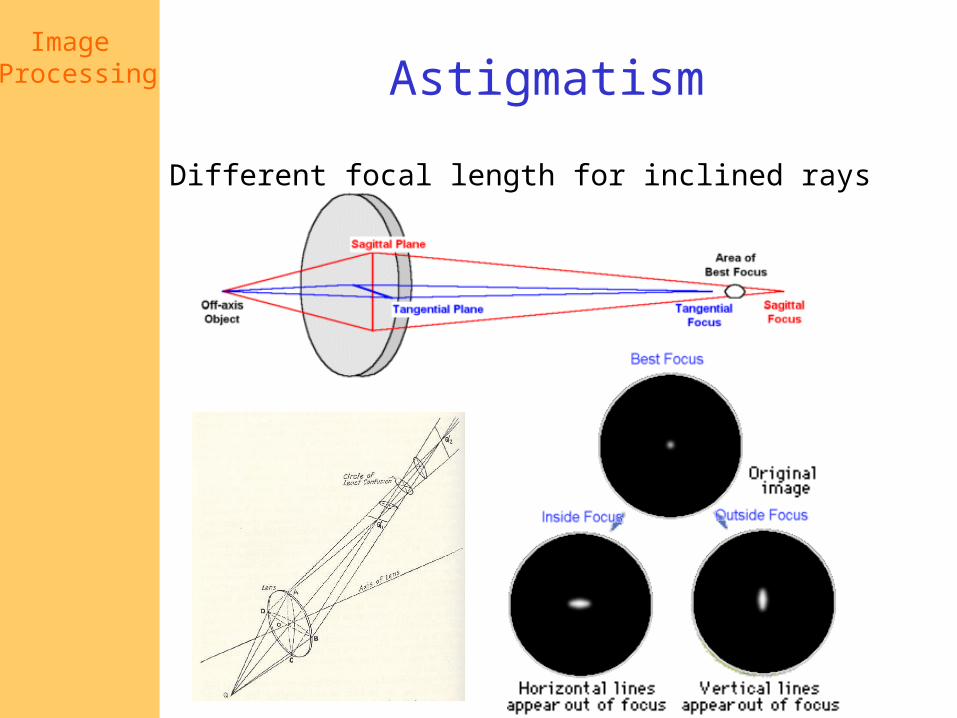
Image Processing Astigmatism
Different focal length for inclined rays
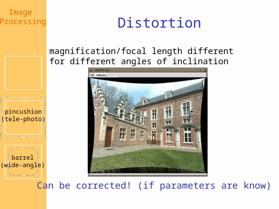
Image Processing Distortion
magnification/focal length different for different angles of inclination
Can be corrected! (if parameters are know)
pincushion(tele-photo)
barrel(wide-angle)

Image Processing Coma
point off the axis depicted as comet shaped blob

Image Processing Chromatic aberration
rays of different wavelengths focused in different planes
cannot be removed completely
sometimes achromatization is achieved formore than 2 wavelengths

Digital cameras• Film sensor array• Often an array of charge coupled
devices• Each CCD is light sensitive diode that
converts photons (light energy) to electrons
cameraCCD array
optics frame grabber computer
K. Grauman

Historical context• Pinhole model: Mozi (470-390 BCE),
Aristotle (384-322 BCE)• Principles of optics (including lenses):
Alhacen (965-1039 CE) • Camera obscura: Leonardo da Vinci
(1452-1519), Johann Zahn (1631-1707)• First photo: Joseph Nicephore Niepce (1822)• Daguerréotypes (1839)• Photographic film (Eastman, 1889)• Cinema (Lumière Brothers, 1895)• Color Photography (Lumière Brothers, 1908)• Television (Baird, Farnsworth, Zworykin, 1920s)• First consumer camera with CCD:
Sony Mavica (1981)• First fully digital camera: Kodak DCS100 (1990)
Niepce, “La Table Servie,” 1822
CCD chip
Alhacen’s notes
Slide credit: L. Lazebnik K. Grauman


Digital Sensors

Image Processing CCD vs. CMOS
• Mature technology• Specific technology• High production cost• High power
consumption• Higher fill rate• Blooming• Sequential readout
• Recent technology• Standard IC technology• Cheap• Low power• Less sensitive• Per pixel amplification• Random pixel access• Smart pixels• On chip integration
with other components

Resolution• sensor: size of real world scene element a that
images to a single pixel• image: number of pixels• Influences what analysis is feasible, affects best
representation choice.
[fig from Mori et al]

Digital imagesThink of images as matrices taken from CCD array.
K. Grauman

im[176][201] has value 164 im[194][203] has value 37
width 520j=1
500 height
i=1Intensity : [0,255]
Digital images
K. Grauman

Color sensing in digital cameras
Source: Steve Seitz
Estimate missing components from neighboring values(demosaicing)
Bayer grid

Filter mosaic
Coat filter directly on sensor
Demosaicing (obtain full colour & full resolution image)

new color CMOS sensorFoveon’s X3
better image qualitysmarter pixels

R G B
Color images, RGB color space
K. GraumanMuch more on color in next lecture…

Issues with digital camerasNoise
– big difference between consumer vs. SLR-style cameras– low light is where you most notice noise
Compression– creates artifacts except in uncompressed formats (tiff, raw)
Color– color fringing artifacts from Bayer patterns
Blooming– charge overflowing into neighboring pixels
In-camera processing– oversharpening can produce halos
Interlaced vs. progressive scan video– even/odd rows from different exposures
Are more megapixels better?– requires higher quality lens– noise issues
Stabilization– compensate for camera shake (mechanical vs. electronic)
More info online, e.g.,• http://electronics.howstuffworks.com/digital-camera.htm • http://www.dpreview.com/

Image Processing
Other Cameras: Line Scan Cameras
Line scanner•The active element is 1-dimensional•Usually employed for inspection
•They require to have very intense light due to small integration time (from100msec to 1msec)

Image Processing The Human Eye
Helmoltz’s SchematicEye
Reproduced by permission, the American Society of Photogrammetry andRemote Sensing. A.L. Nowicki, “Stereoscopy.” Manual of Photogrammetry,Thompson, Radlinski, and Speert (eds.), third edition, 1966.

Image Processing The distribution of
rods and cones across the retina
Reprinted from Foundations of Vision, by B. Wandell, Sinauer Associates, Inc., (1995). 1995 Sinauer Associates, Inc.
Cones in the fovea
Rods and cones in the periphery
Reprinted from Foundations of Vision, by B. Wandell, Sinauer Associates, Inc., (1995). 1995 Sinauer Associates, Inc.