Embed Size (px)
Citation preview
Calibration Protocol DMC II 230 – 017
CalibProtocol_DMCII230-017_2014.docx Document Version 3.0 page 1 of 40
Camera Calibration Certificate
No: DMC II 230 – 017
For
Richard Crouse & Associates 467 Aviation Way
Frederick, MD 21701
USA
DMC II 230 Calibration Protocol
CalibProtocol_DMCII230-017_2014.docx Document Version 3.0 page 2 of 40
Camera: DMC II 230
Manufacturer : Intergraph Z/I Deutschland GmbH, D-73431 Aalen, Germany
Reference: PAN
Serial Number: 00119895 (PAN Head)
Date of Calibration: 22. February 2011
Date of Report: 8. March 2011
Number of Pages:
Calibration performed at: Carl Zeiss Jena, Carl-Zeiss-Promenade 10, 07745 Jena, Germany.
This camera system is certified by Z/I Imaging and is fully functional within its specifications and tolerances.
Date of Calibration: February 2011 Date of Certification: March 2011
Jürgen Hefele, Senior Software Developer Dipl.Ing. Christian Müller, Technical Consultant
DMC II 230 Calibration Protocol
CalibProtocol_DMCII230-017_2014.docx Document Version 3.0 page 3 of 40
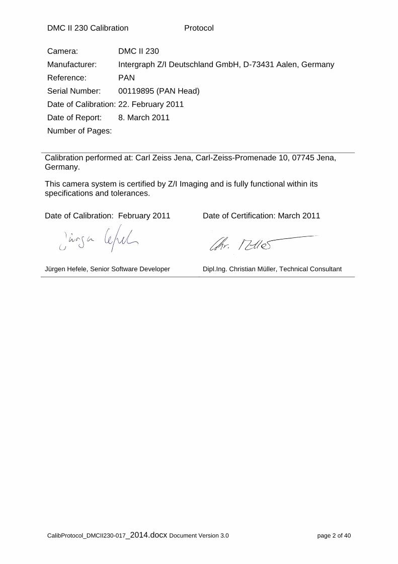
Camera Serial Numbers and Burn-In flight
Camera Head Serial Number
Calib. Date
PAN (reference)
00119895 22.02.2011
MS1 (NIR) 00118806 14.01.2011
MS2 (Blue) 00118818 14.01.2011
MS3 (Red) 00118809 14.01.2011
MS4 (Green) 00118843 17.01.2011
Burn-In flight performed: 23. February 2011
Test block configuration
Photo Scale 1:8928.6
Flying Height [m] 821.4 AGL
Flying Altitude [m]
1271.4 AMSL
Run-Spacing [m] 544.3
Base-Length [m] 282.9
Number of Exposures
54
Side-lap [%] 30
End-lap [%] 60
Terrain Height [m]
450
Number of strips 6
Photos in one strip
2 x 9 N-S 4 x 9 W-E
Photos Used 54
Control Points Used
9
Check Points Used
32
GSD [cm] 5
DMC II 230 Calibration Protocol
CalibProtocol_DMCII230-017_2014.docx Document Version 3.0 page 4 of 40
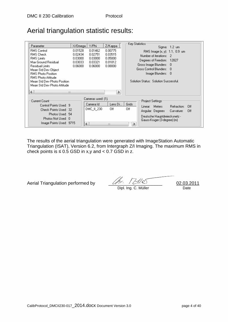
Aerial triangulation statistic results:
The results of the aerial triangulation were generated with ImageStation Automatic Triangulation (ISAT), Version 6.2, from Intergraph Z/I Imaging. The maximum RMS in check points is ≤ 0.5 GSD in x,y and < 0.7 GSD in z. Aerial Triangulation performed by _____________________ 02.03.2011 Dipl. Ing. C. Müller Date
DMC II 230 Calibration Protocol
CalibProtocol_DMCII230-017_2014.docx Document Version 3.0 page 5 of 40
Geometric Calibration The output image geometry is based on the Pan Camera head (reference head = master camera). All other camera heads are registered and aligned to this head. Aerial triangulation checks overall system performance based on.
Output image
Reference Camera PAN
Serial Number 00119895
Number of rows/columns [pixels] 15552 x 14144
Pixel Size [m] 5.600 x 5.600
Image Size [mm] 87.0912 x 79.2064
Focal Length [mm] 92.0005 mm + /- 0.002 mm
Principal Point [mm] X= 0.0030 mm,
Y= 0.0020 mm
+ /- 0.002 mm
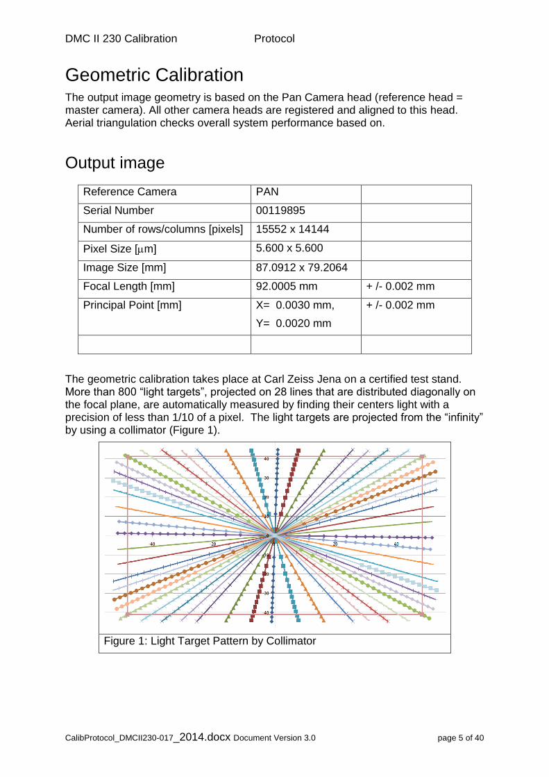
The geometric calibration takes place at Carl Zeiss Jena on a certified test stand. More than 800 “light targets”, projected on 28 lines that are distributed diagonally on the focal plane, are automatically measured by finding their centers light with a precision of less than 1/10 of a pixel. The light targets are projected from the “infinity” by using a collimator (Figure 1).
Figure 1: Light Target Pattern by Collimator
DMC II 230 Calibration Protocol
CalibProtocol_DMCII230-017_2014.docx Document Version 3.0 page 6 of 40
Geometric Calibration
Image Residuals
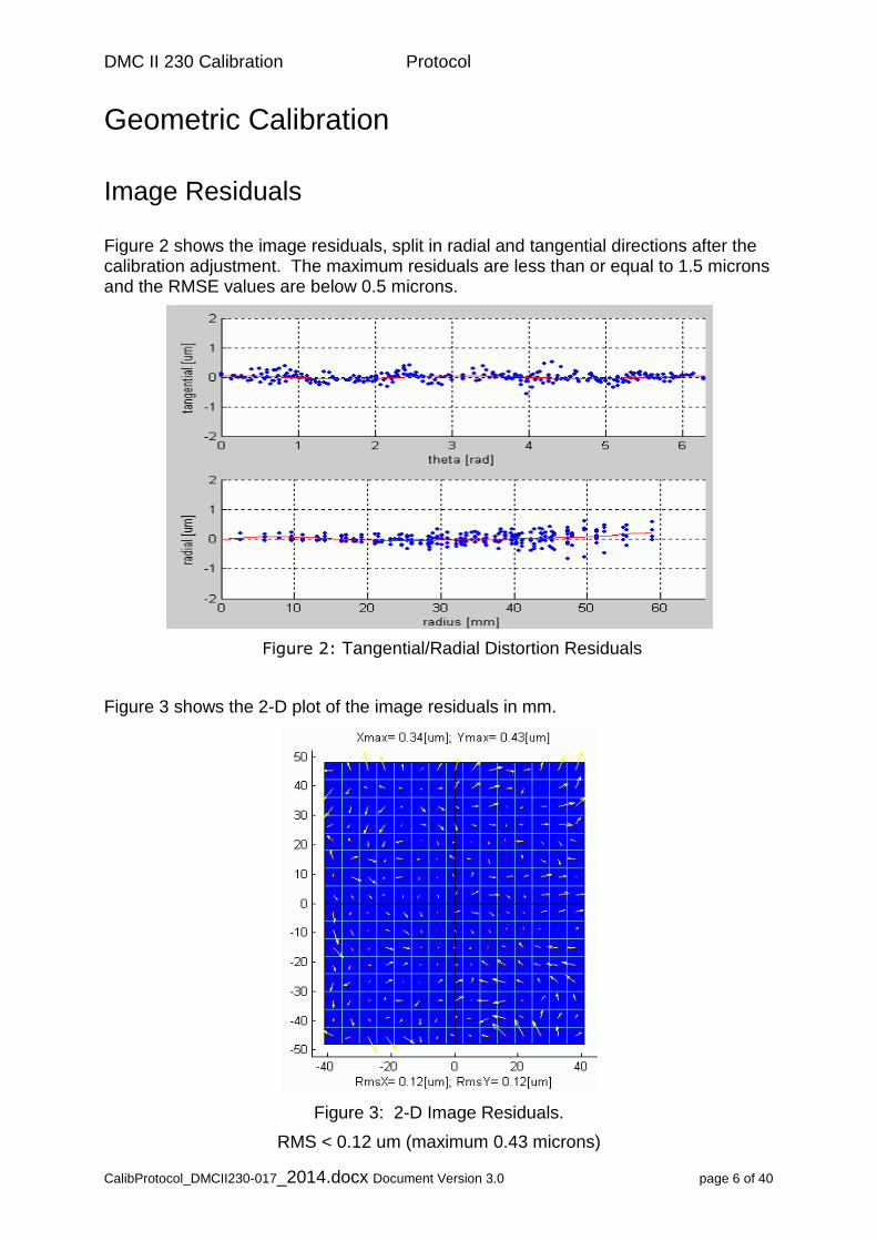
Figure 2 shows the image residuals, split in radial and tangential directions after the calibration adjustment. The maximum residuals are less than or equal to 1.5 microns and the RMSE values are below 0.5 microns.
Figure 2: Tangential/Radial Distortion Residuals
Figure 3 shows the 2-D plot of the image residuals in mm.
Figure 3: 2-D Image Residuals.
RMS < 0.12 um (maximum 0.43 microns)
DMC II 230 Calibration Protocol
CalibProtocol_DMCII230-017_2014.docx Document Version 3.0 page 7 of 40
Optical System
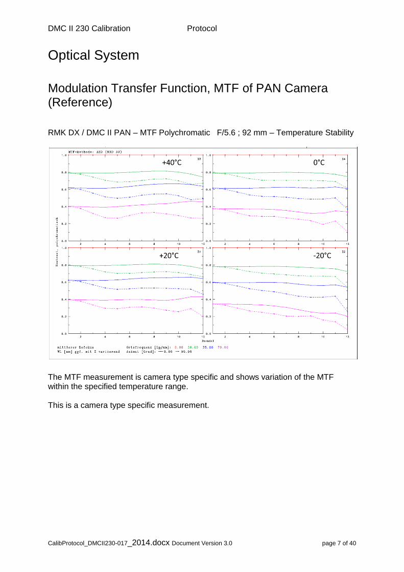
Modulation Transfer Function, MTF of PAN Camera (Reference) RMK DX / DMC II PAN – MTF Polychromatic F/5.6 ; 92 mm – Temperature Stability
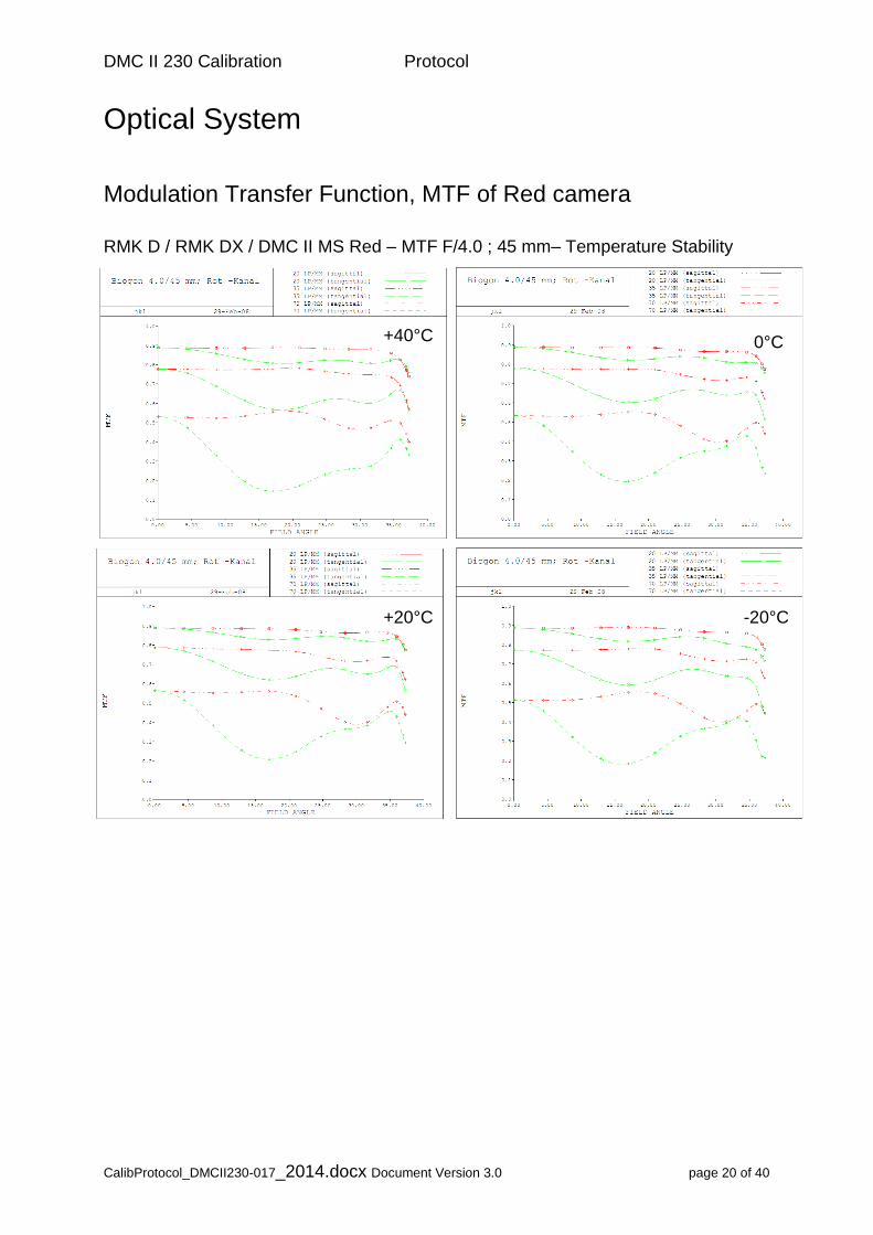
The MTF measurement is camera type specific and shows variation of the MTF within the specified temperature range. This is a camera type specific measurement.
DMC II 230 Calibration Protocol
CalibProtocol_DMCII230-017_2014.docx Document Version 3.0 page 8 of 40
Radiometric Calibration
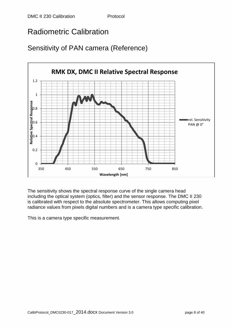
Sensitivity of PAN camera (Reference)
The sensitivity shows the spectral response curve of the single camera head including the optical system (optics, filter) and the sensor response. The DMC II 230 is calibrated with respect to the absolute spectrometer. This allows computing pixel radiance values from pixels digital numbers and is a camera type specific calibration. This is a camera type specific measurement.
0
0.2
0.4
0.6
0.8
1
1.2
350 450 550 650 750 850
Re
lati
ve S
pe
ctra
l Re
spo
nse
Wavelength [nm]
RMK DX, DMC II Relative Spectral Response
rel. SensitivityPAN @ 0°
DMC II 230 Calibration Protocol
CalibProtocol_DMCII230-017_2014.docx Document Version 3.0 page 9 of 40
Radiometric Calibration
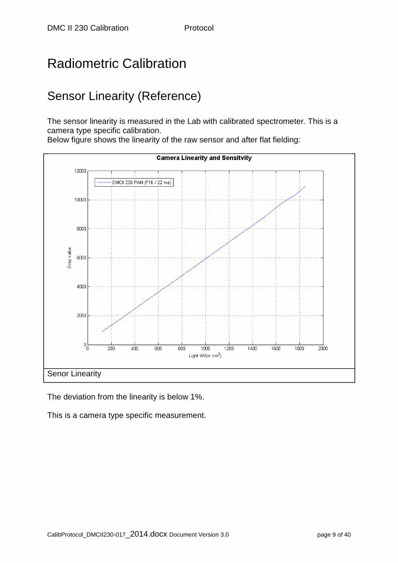
Sensor Linearity (Reference) The sensor linearity is measured in the Lab with calibrated spectrometer. This is a camera type specific calibration. Below figure shows the linearity of the raw sensor and after flat fielding:
Senor Linearity
The deviation from the linearity is below 1%. This is a camera type specific measurement.
DMC II 230 Calibration Protocol
CalibProtocol_DMCII230-017_2014.docx Document Version 3.0 page 10 of 40
Radiometric Calibration
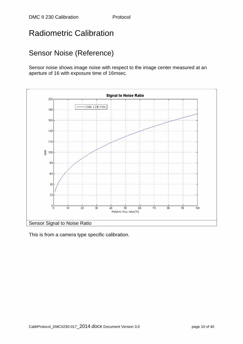
Sensor Noise (Reference) Sensor noise shows image noise with respect to the image center measured at an aperture of 16 with exposure time of 16msec.
Sensor Signal to Noise Ratio
This is from a camera type specific calibration.
DMC II 230 Calibration Protocol
CalibProtocol_DMCII230-017_2014.docx Document Version 3.0 page 11 of 40
Radiometric Calibration
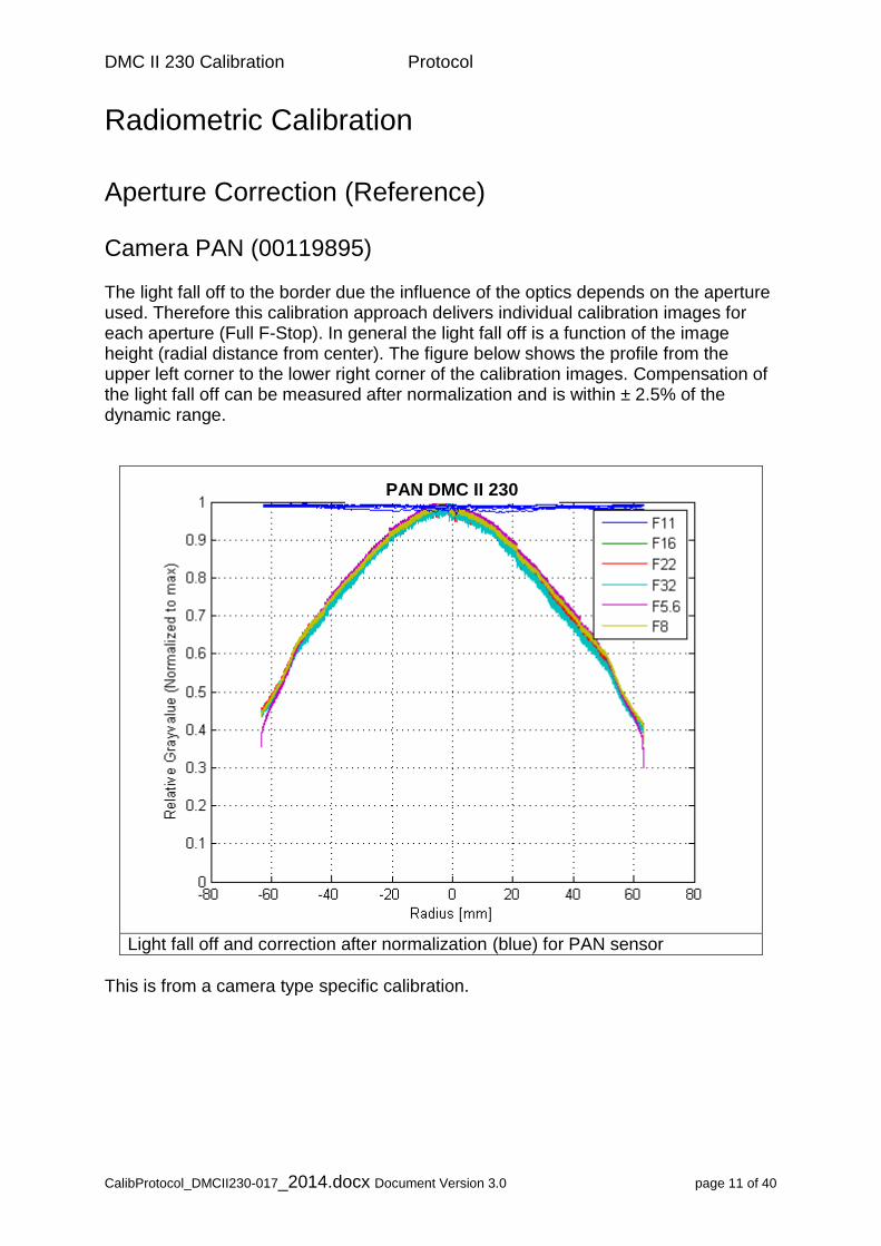
Aperture Correction (Reference) Camera PAN (00119895) The light fall off to the border due the influence of the optics depends on the aperture used. Therefore this calibration approach delivers individual calibration images for each aperture (Full F-Stop). In general the light fall off is a function of the image height (radial distance from center). The figure below shows the profile from the upper left corner to the lower right corner of the calibration images. Compensation of the light fall off can be measured after normalization and is within ± 2.5% of the dynamic range.
Light fall off and correction after normalization (blue) for PAN sensor
This is from a camera type specific calibration.
PAN DMC II 230
DMC II 230 Calibration Protocol
CalibProtocol_DMCII230-017_2014.docx Document Version 3.0 page 12 of 40
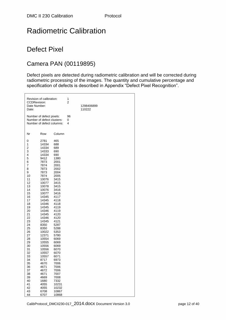
Radiometric Calibration
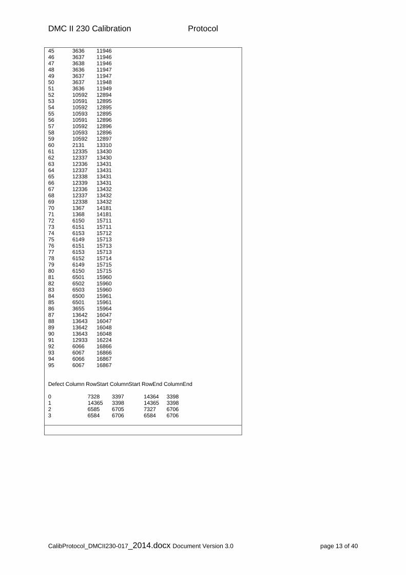
Defect Pixel Camera PAN (00119895) Defect pixels are detected during radiometric calibration and will be corrected during radiometric processing of the images. The quantity and cumulative percentage and specification of defects is described in Appendix “Defect Pixel Recognition”. Revision of calibration: 1 CCDRevision: 2 Date Number: 1298406899 Date: 110222 Number of defect pixels: 96 Number of defect clusters: 0 Number of defect columns: 4 Nr Row Column 0 2781 465 1 14334 688 2 14334 689 3 14333 690 4 14334 690 5 9412 1380 6 7873 2001 7 7874 2001 8 7873 2002 9 7873 2004 10 7874 2005 11 10076 3415 12 10077 3415 13 10078 3415 14 10076 3416 15 10077 3416 16 14345 4117 17 14345 4118 18 14346 4118 19 14345 4119 20 14346 4119 21 14345 4120 22 14346 4120 23 14345 4121 24 8350 5287 25 8350 5288 26 10022 5353 27 12371 5780 28 10554 6069 29 10555 6069 30 10556 6069 31 10556 6070 32 10557 6070 33 10557 6071 34 8717 6973 35 4670 7006 36 4671 7006 37 4672 7006 38 4671 7007 39 4669 7008 40 1680 7332 41 4055 10231 42 4055 10232 43 6708 10867 44 6707 10868
DMC II 230 Calibration Protocol
CalibProtocol_DMCII230-017_2014.docx Document Version 3.0 page 13 of 40
45 3636 11946 46 3637 11946 47 3638 11946 48 3636 11947 49 3637 11947 50 3637 11948 51 3636 11949 52 10592 12894 53 10591 12895 54 10592 12895 55 10593 12895 56 10591 12896 57 10592 12896 58 10593 12896 59 10592 12897 60 2131 13310 61 12335 13430 62 12337 13430 63 12336 13431 64 12337 13431 65 12338 13431 66 12339 13431 67 12336 13432 68 12337 13432 69 12338 13432 70 1367 14181 71 1368 14181 72 6150 15711 73 6151 15711 74 6153 15712 75 6149 15713 76 6151 15713 77 6153 15713 78 6152 15714 79 6149 15715 80 6150 15715 81 6501 15960 82 6502 15960 83 6503 15960 84 6500 15961 85 6501 15961 86 3655 15964 87 13642 16047 88 13643 16047 89 13642 16048 90 13643 16048 91 12933 16224 92 6066 16866 93 6067 16866 94 6066 16867 95 6067 16867 Defect Column RowStart ColumnStart RowEnd ColumnEnd 0 7328 3397 14364 3398 1 14365 3398 14365 3398 2 6585 6705 7327 6706 3 6584 6706 6584 6706
DMC II 230 Calibration Protocol
CalibProtocol_DMCII230-017_2014.docx Document Version 3.0 page 14 of 40
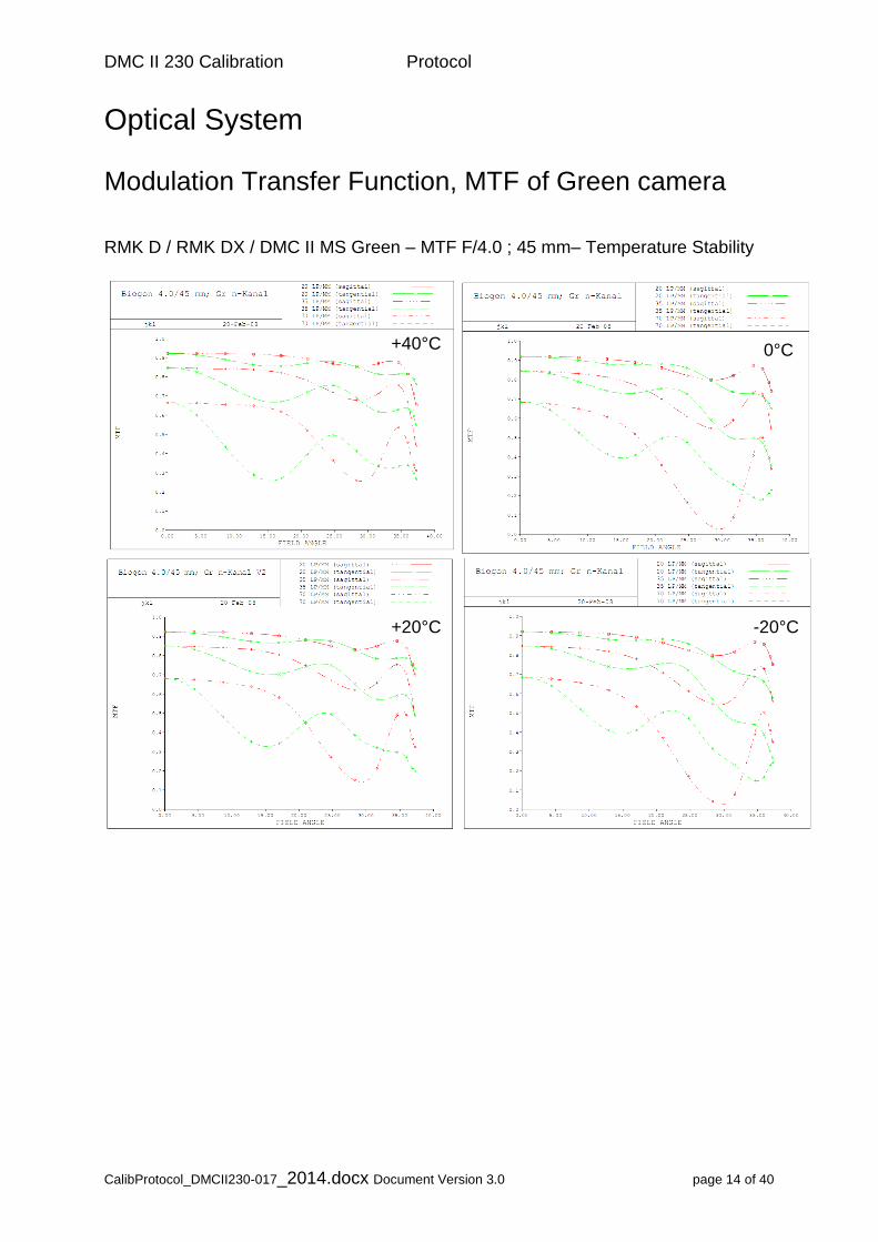
Optical System
Modulation Transfer Function, MTF of Green camera RMK D / RMK DX / DMC II MS Green – MTF F/4.0 ; 45 mm– Temperature Stability
+40°C 0°C
+20°C -20°C
DMC II 230 Calibration Protocol
CalibProtocol_DMCII230-017_2014.docx Document Version 3.0 page 15 of 40
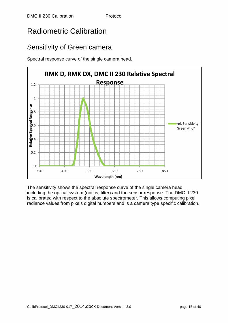
Radiometric Calibration
Sensitivity of Green camera Spectral response curve of the single camera head.
The sensitivity shows the spectral response curve of the single camera head including the optical system (optics, filter) and the sensor response. The DMC II 230 is calibrated with respect to the absolute spectrometer. This allows computing pixel radiance values from pixels digital numbers and is a camera type specific calibration.
0
0.2
0.4
0.6
0.8
1
1.2
350 450 550 650 750 850
Re
lati
ve S
pe
ctra
l Re
spo
nse
Wavelength [nm]
RMK D, RMK DX, DMC II 230 Relative Spectral Response
rel. SensitivityGreen @ 0°
DMC II 230 Calibration Protocol
CalibProtocol_DMCII230-017_2014.docx Document Version 3.0 page 16 of 40
Radiometric Calibration
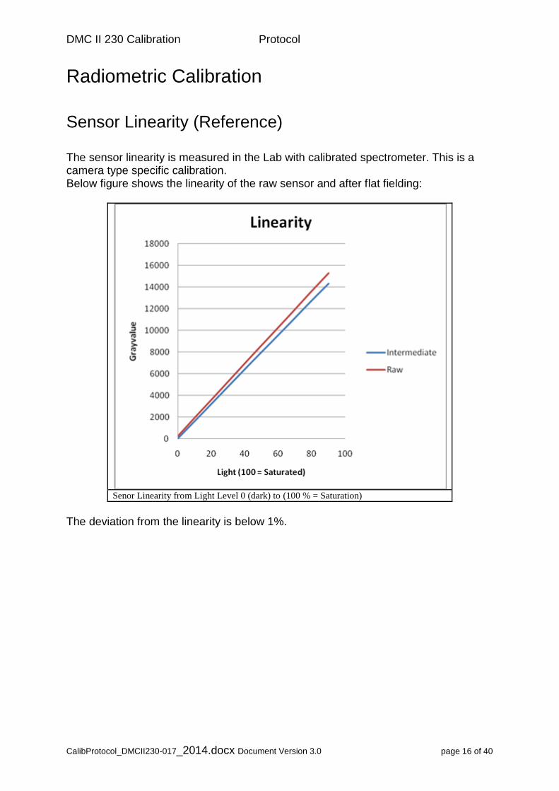
Sensor Linearity (Reference) The sensor linearity is measured in the Lab with calibrated spectrometer. This is a camera type specific calibration. Below figure shows the linearity of the raw sensor and after flat fielding:
Senor Linearity from Light Level 0 (dark) to (100 % = Saturation)
The deviation from the linearity is below 1%.
DMC II 230 Calibration Protocol
CalibProtocol_DMCII230-017_2014.docx Document Version 3.0 page 17 of 40
Radiometric Calibration
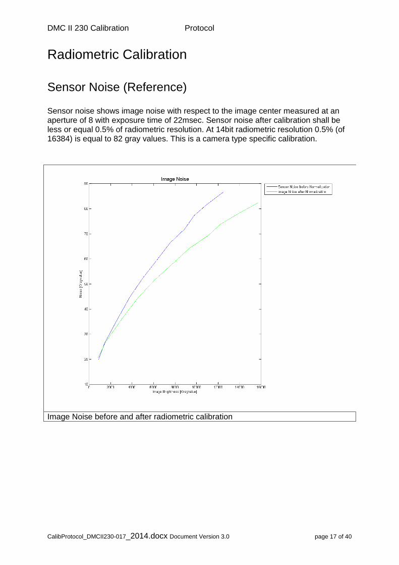
Sensor Noise (Reference) Sensor noise shows image noise with respect to the image center measured at an aperture of 8 with exposure time of 22msec. Sensor noise after calibration shall be less or equal 0.5% of radiometric resolution. At 14bit radiometric resolution 0.5% (of 16384) is equal to 82 gray values. This is a camera type specific calibration.
Image Noise before and after radiometric calibration
DMC II 230 Calibration Protocol
CalibProtocol_DMCII230-017_2014.docx Document Version 3.0 page 18 of 40
Radiometric Calibration
Aperture Correction
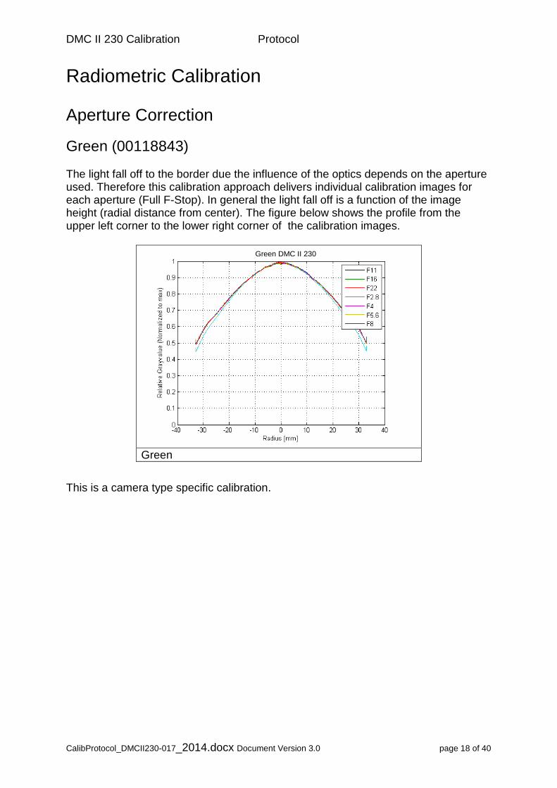
Green (00118843) The light fall off to the border due the influence of the optics depends on the aperture used. Therefore this calibration approach delivers individual calibration images for each aperture (Full F-Stop). In general the light fall off is a function of the image height (radial distance from center). The figure below shows the profile from the upper left corner to the lower right corner of the calibration images.
Green
This is a camera type specific calibration.
Green DMC II 230
DMC II 230 Calibration Protocol
CalibProtocol_DMCII230-017_2014.docx Document Version 3.0 page 19 of 40
Radiometric Calibration
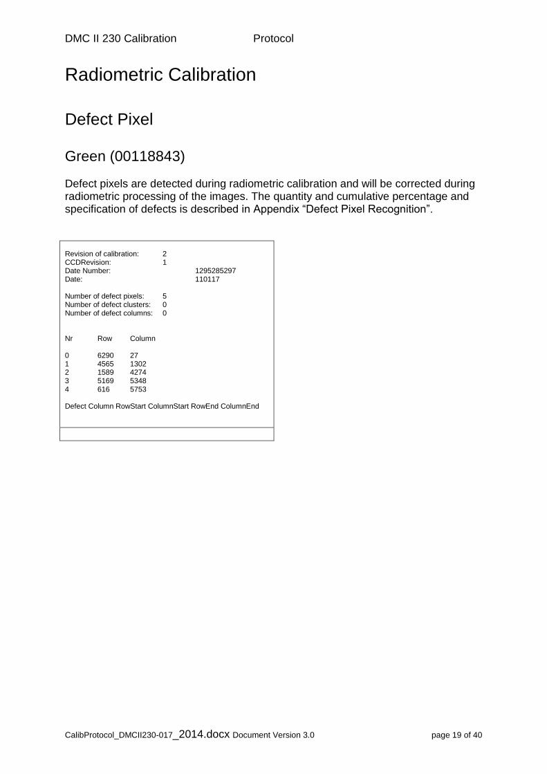
Defect Pixel Green (00118843) Defect pixels are detected during radiometric calibration and will be corrected during radiometric processing of the images. The quantity and cumulative percentage and specification of defects is described in Appendix “Defect Pixel Recognition”. Revision of calibration: 2 CCDRevision: 1 Date Number: 1295285297 Date: 110117 Number of defect pixels: 5 Number of defect clusters: 0 Number of defect columns: 0 Nr Row Column 0 6290 27 1 4565 1302 2 1589 4274 3 5169 5348 4 616 5753 Defect Column RowStart ColumnStart RowEnd ColumnEnd
DMC II 230 Calibration Protocol
CalibProtocol_DMCII230-017_2014.docx Document Version 3.0 page 20 of 40
Optical System
Modulation Transfer Function, MTF of Red camera
RMK D / RMK DX / DMC II MS Red – MTF F/4.0 ; 45 mm– Temperature Stability
+40°C 0°C
+20°C -20°C
DMC II 230 Calibration Protocol
CalibProtocol_DMCII230-017_2014.docx Document Version 3.0 page 21 of 40
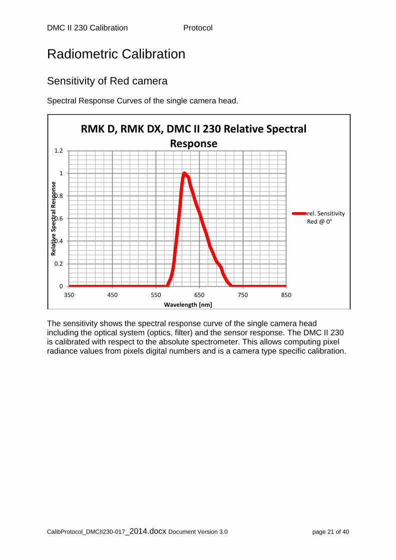
Radiometric Calibration
Sensitivity of Red camera Spectral Response Curves of the single camera head.
The sensitivity shows the spectral response curve of the single camera head including the optical system (optics, filter) and the sensor response. The DMC II 230 is calibrated with respect to the absolute spectrometer. This allows computing pixel radiance values from pixels digital numbers and is a camera type specific calibration.
0
0.2
0.4
0.6
0.8
1
1.2
350 450 550 650 750 850
Re
lati
ve S
pe
ctra
l Re
spo
nse
Wavelength [nm]
RMK D, RMK DX, DMC II 230 Relative Spectral Response
rel. SensitivityRed @ 0°

DMC II 230 Calibration Protocol
CalibProtocol_DMCII230-017_2014.docx Document Version 3.0 page 22 of 40
Radiometric Calibration
Sensor Linearity (Reference) The sensor linearity is measured in the Lab with calibrated spectrometer. This is a camera type specific calibration. Below figure shows the linearity of the raw sensor and after flat fielding:
Senor Linearity from Light Level 0 (dark) to (100 % = Saturation)
The deviation from the linearity is below 1%.

DMC II 230 Calibration Protocol
CalibProtocol_DMCII230-017_2014.docx Document Version 3.0 page 23 of 40
Radiometric Calibration
Sensor Noise (Reference) Sensor noise shows image noise with respect to the image center measured at an aperture of 8 with exposure time of 22msec. Sensor noise after calibration shall be less or equal 0.5% of radiometric resolution. At 14bit radiometric resolution 0.5% (of 16384) is equal to 82 gray values. This is a camera type specific calibration.
Image Noise before and after radiometric calibration
DMC II 230 Calibration Protocol
CalibProtocol_DMCII230-017_2014.docx Document Version 3.0 page 24 of 40
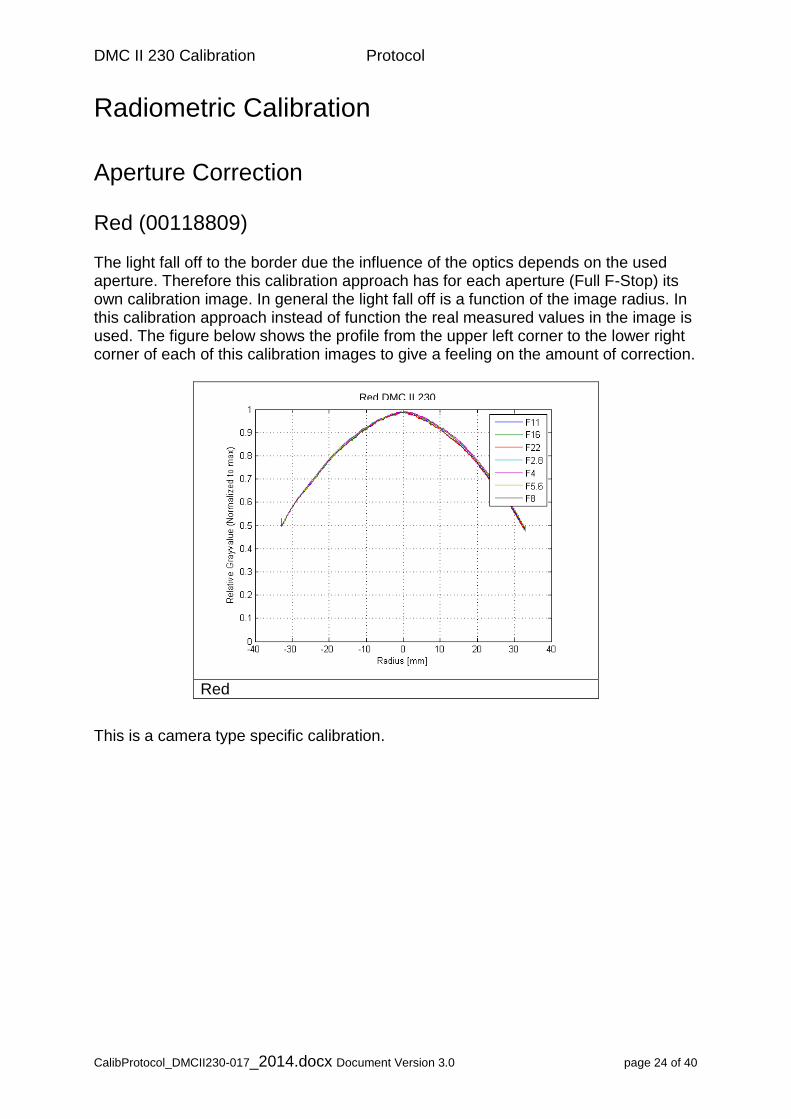
Radiometric Calibration
Aperture Correction Red (00118809) The light fall off to the border due the influence of the optics depends on the used aperture. Therefore this calibration approach has for each aperture (Full F-Stop) its own calibration image. In general the light fall off is a function of the image radius. In this calibration approach instead of function the real measured values in the image is used. The figure below shows the profile from the upper left corner to the lower right corner of each of this calibration images to give a feeling on the amount of correction.
Red
This is a camera type specific calibration.
Red DMC II 230
DMC II 230 Calibration Protocol
CalibProtocol_DMCII230-017_2014.docx Document Version 3.0 page 25 of 40
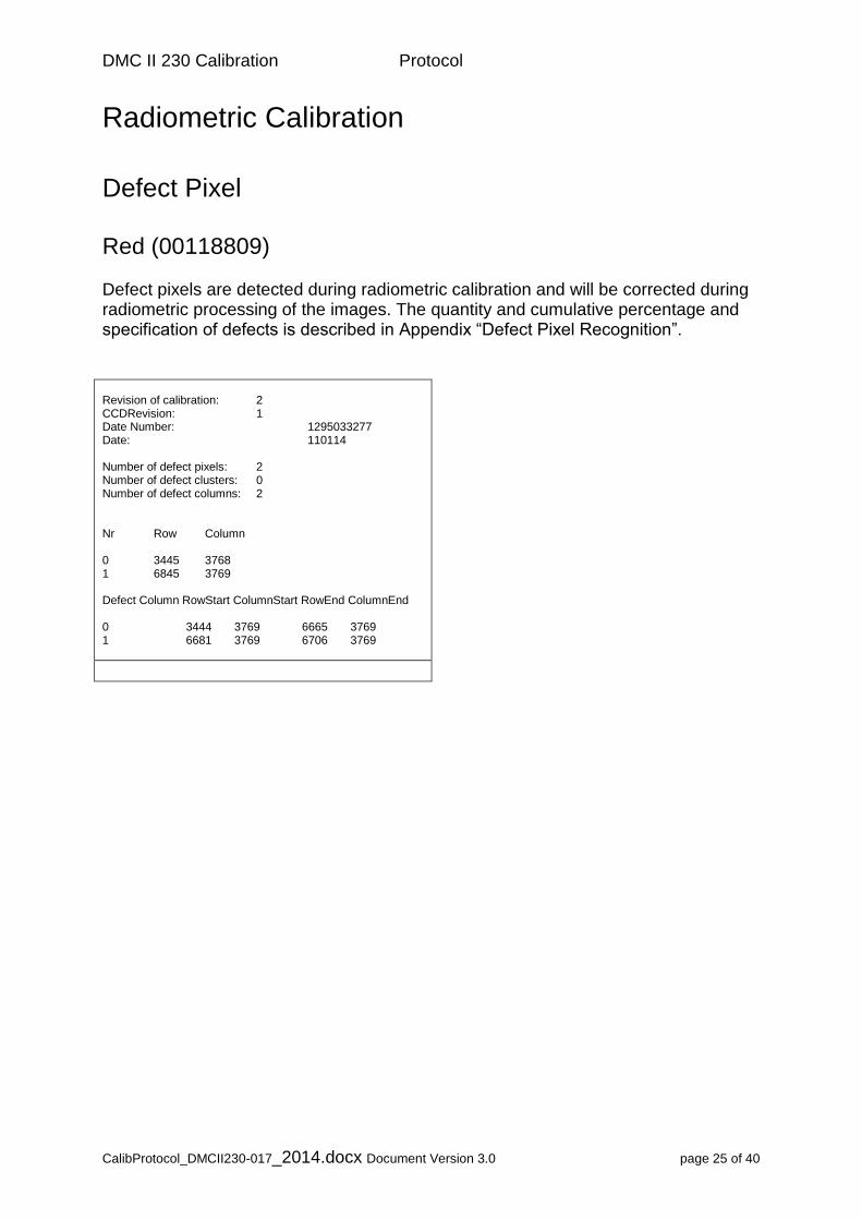
Radiometric Calibration
Defect Pixel Red (00118809) Defect pixels are detected during radiometric calibration and will be corrected during radiometric processing of the images. The quantity and cumulative percentage and specification of defects is described in Appendix “Defect Pixel Recognition”. Revision of calibration: 2 CCDRevision: 1 Date Number: 1295033277 Date: 110114 Number of defect pixels: 2 Number of defect clusters: 0 Number of defect columns: 2 Nr Row Column 0 3445 3768 1 6845 3769 Defect Column RowStart ColumnStart RowEnd ColumnEnd 0 3444 3769 6665 3769 1 6681 3769 6706 3769
DMC II 230 Calibration Protocol
CalibProtocol_DMCII230-017_2014.docx Document Version 3.0 page 26 of 40
Optical System
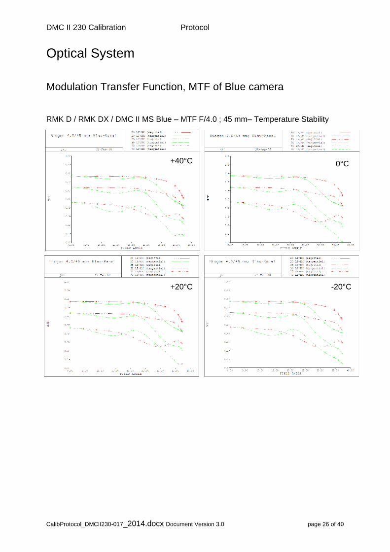
Modulation Transfer Function, MTF of Blue camera
RMK D / RMK DX / DMC II MS Blue – MTF F/4.0 ; 45 mm– Temperature Stability
+40°C 0°C
+20°C -20°C
DMC II 230 Calibration Protocol
CalibProtocol_DMCII230-017_2014.docx Document Version 3.0 page 27 of 40
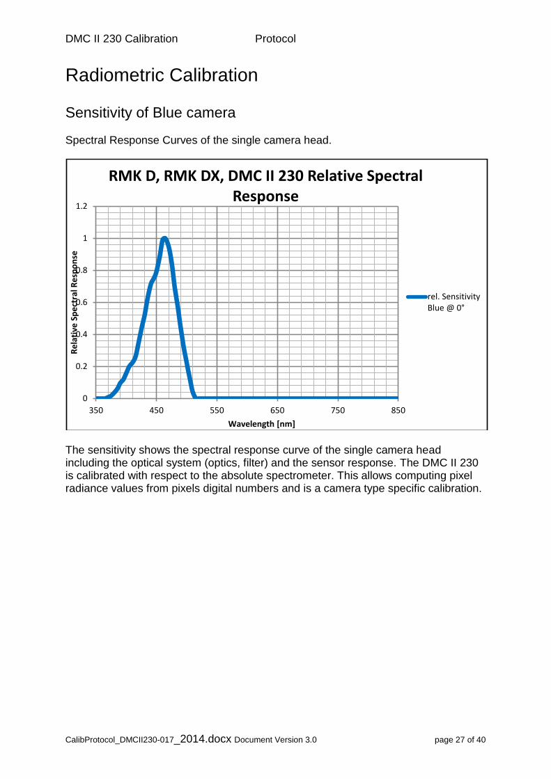
Radiometric Calibration
Sensitivity of Blue camera Spectral Response Curves of the single camera head.
The sensitivity shows the spectral response curve of the single camera head including the optical system (optics, filter) and the sensor response. The DMC II 230 is calibrated with respect to the absolute spectrometer. This allows computing pixel radiance values from pixels digital numbers and is a camera type specific calibration.
0
0.2
0.4
0.6
0.8
1
1.2
350 450 550 650 750 850
Re
lati
ve S
pe
ctra
l Re
spo
nse
Wavelength [nm]
RMK D, RMK DX, DMC II 230 Relative Spectral Response
rel. SensitivityBlue @ 0°

DMC II 230 Calibration Protocol
CalibProtocol_DMCII230-017_2014.docx Document Version 3.0 page 28 of 40
Radiometric Calibration
Sensor Linearity (Reference) The sensor linearity is measured in the Lab with calibrated spectrometer. This is a camera type specific calibration. Below figure shows the linearity of the raw sensor and after flat fielding:
Senor Linearity from Light Level 0 (dark) to (100 % = Saturation)
The deviation from the linearity is below 1%.

DMC II 230 Calibration Protocol
CalibProtocol_DMCII230-017_2014.docx Document Version 3.0 page 29 of 40
Radiometric Calibration
Sensor Noise (Reference) Sensor noise shows image noise with respect to the image center measured at an aperture of 8 with exposure time of 22msec. Sensor noise after calibration shall be less or equal 0.5% of radiometric resolution. At 14bit radiometric resolution 0.5% (of 16384) is equal to 82 gray values. This is a camera type specific calibration.
Image Noise before and after radiometric calibration
DMC II 230 Calibration Protocol
CalibProtocol_DMCII230-017_2014.docx Document Version 3.0 page 30 of 40
Radiometric Calibration
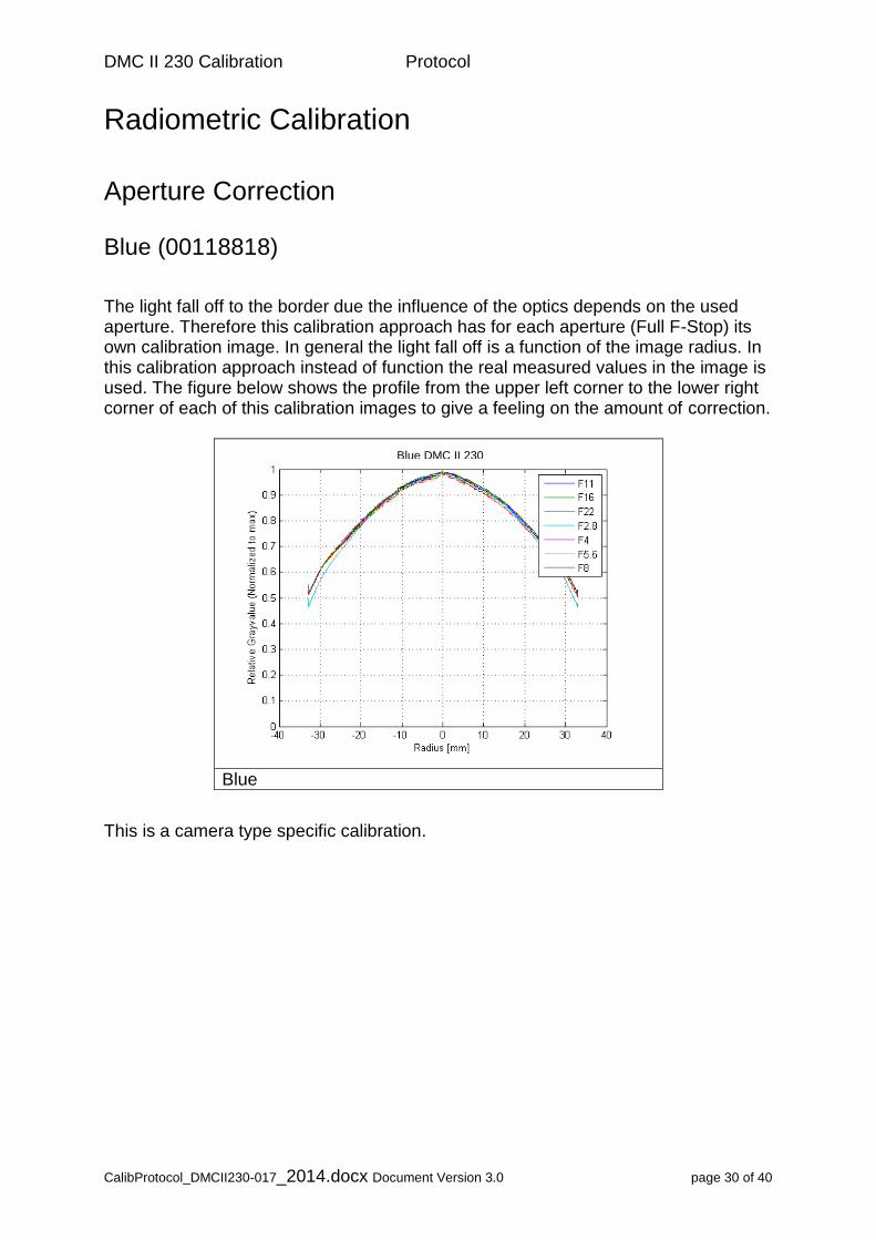
Aperture Correction Blue (00118818)
The light fall off to the border due the influence of the optics depends on the used aperture. Therefore this calibration approach has for each aperture (Full F-Stop) its own calibration image. In general the light fall off is a function of the image radius. In this calibration approach instead of function the real measured values in the image is used. The figure below shows the profile from the upper left corner to the lower right corner of each of this calibration images to give a feeling on the amount of correction.
Blue
This is a camera type specific calibration.
Blue DMC II 230
DMC II 230 Calibration Protocol
CalibProtocol_DMCII230-017_2014.docx Document Version 3.0 page 31 of 40
Radiometric Calibration
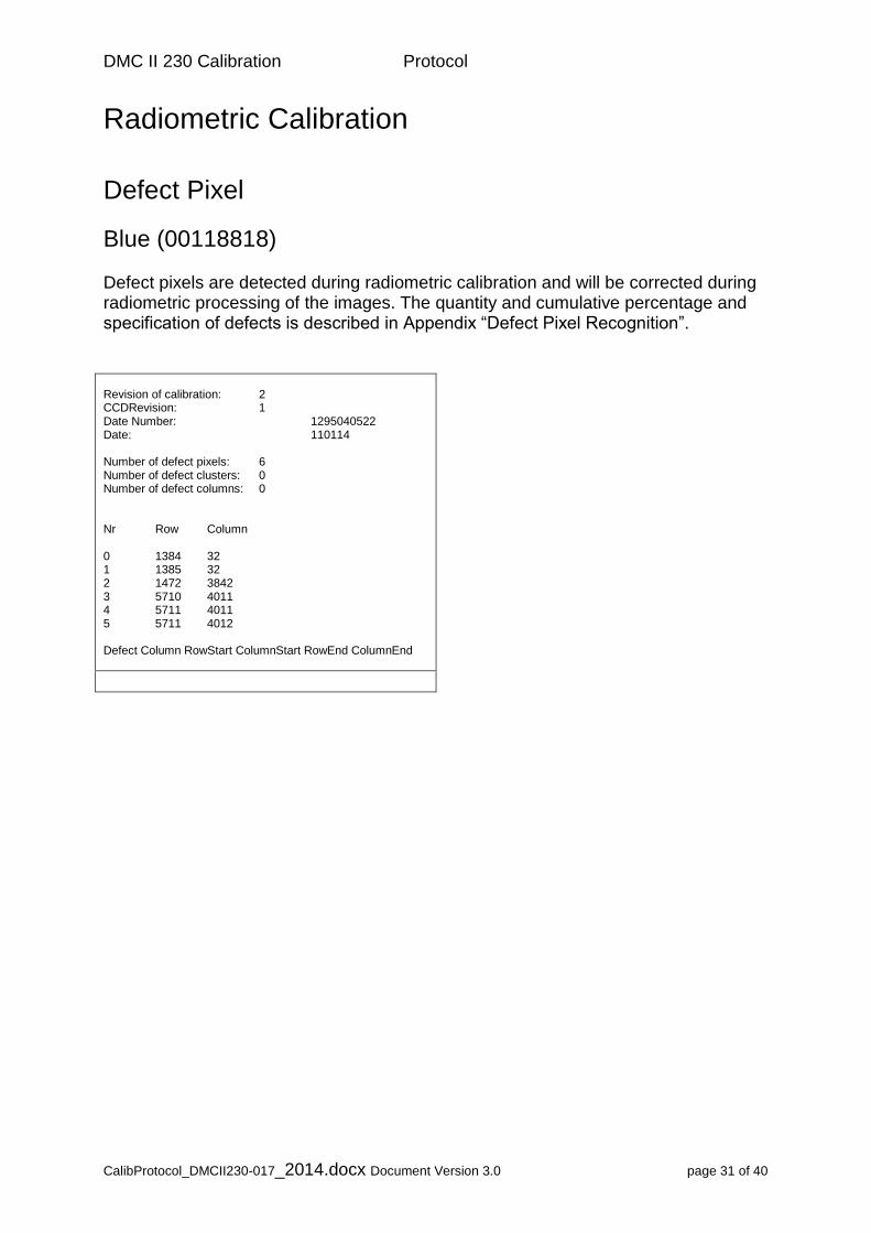
Defect Pixel
Blue (00118818) Defect pixels are detected during radiometric calibration and will be corrected during radiometric processing of the images. The quantity and cumulative percentage and specification of defects is described in Appendix “Defect Pixel Recognition”. Revision of calibration: 2 CCDRevision: 1 Date Number: 1295040522 Date: 110114 Number of defect pixels: 6 Number of defect clusters: 0 Number of defect columns: 0 Nr Row Column 0 1384 32 1 1385 32 2 1472 3842 3 5710 4011 4 5711 4011 5 5711 4012 Defect Column RowStart ColumnStart RowEnd ColumnEnd
DMC II 230 Calibration Protocol
CalibProtocol_DMCII230-017_2014.docx Document Version 3.0 page 32 of 40
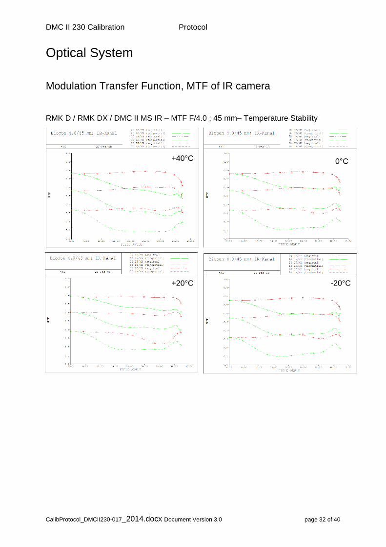
Optical System
Modulation Transfer Function, MTF of IR camera
RMK D / RMK DX / DMC II MS IR – MTF F/4.0 ; 45 mm– Temperature Stability
+40°C 0°C
+20°C -20°C
DMC II 230 Calibration Protocol
CalibProtocol_DMCII230-017_2014.docx Document Version 3.0 page 33 of 40
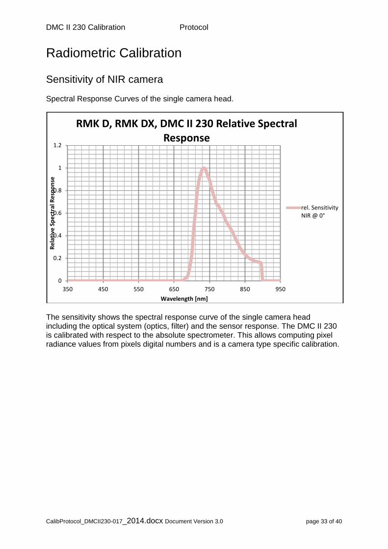
Radiometric Calibration
Sensitivity of NIR camera Spectral Response Curves of the single camera head.
The sensitivity shows the spectral response curve of the single camera head including the optical system (optics, filter) and the sensor response. The DMC II 230 is calibrated with respect to the absolute spectrometer. This allows computing pixel radiance values from pixels digital numbers and is a camera type specific calibration.
0
0.2
0.4
0.6
0.8
1
1.2
350 450 550 650 750 850 950
Re
lati
ve S
pe
ctra
l Re
spo
nse
Wavelength [nm]
RMK D, RMK DX, DMC II 230 Relative Spectral Response
rel. SensitivityNIR @ 0°

DMC II 230 Calibration Protocol
CalibProtocol_DMCII230-017_2014.docx Document Version 3.0 page 34 of 40
Radiometric Calibration
Sensor Linearity (Reference) The sensor linearity is measured in the Lab with calibrated spectrometer. This is a camera type specific calibration. Below figure shows the linearity of the raw sensor and after flat fielding:
Senor Linearity from Light Level 0 (dark) to (100 % = Saturation)
The deviation from the linearity is below 1%.

DMC II 230 Calibration Protocol
CalibProtocol_DMCII230-017_2014.docx Document Version 3.0 page 35 of 40
Radiometric Calibration
Sensor Noise (Reference) Sensor noise shows image noise with respect to the image center measured at an aperture of 8 with exposure time of 22msec. Sensor noise after calibration shall be less or equal 0.5% of radiometric resolution. At 14bit radiometric resolution 0.5% (of 16384) is equal to 82 gray values. This is a camera type specific calibration.
Image Noise before and after radiometric calibration
DMC II 230 Calibration Protocol
CalibProtocol_DMCII230-017_2014.docx Document Version 3.0 page 36 of 40
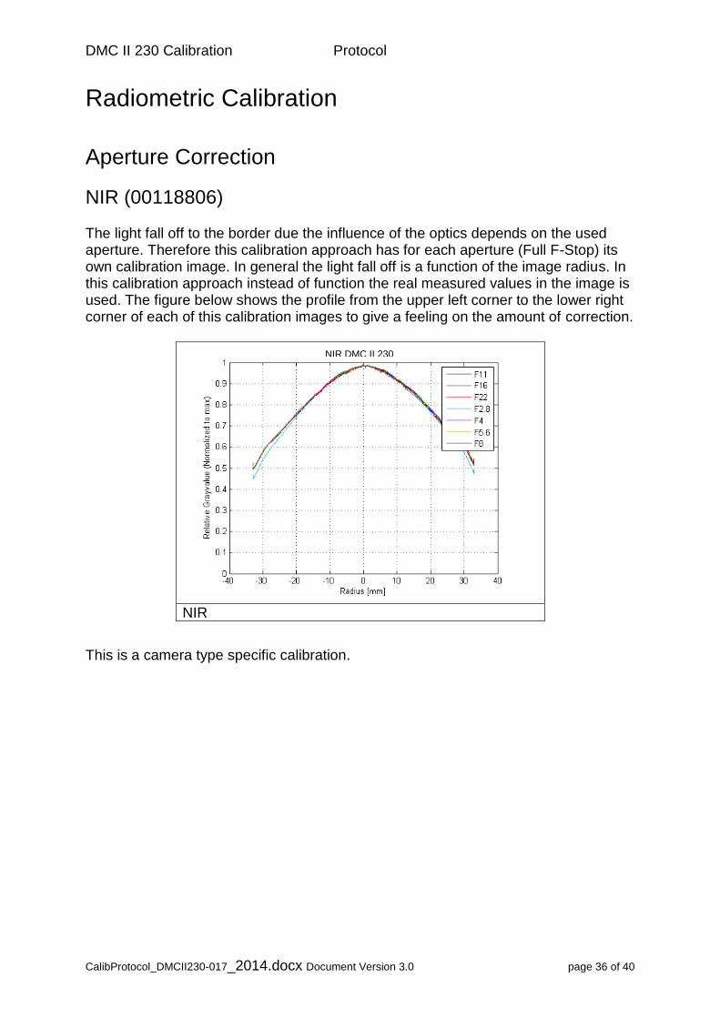
Radiometric Calibration
Aperture Correction
NIR (00118806) The light fall off to the border due the influence of the optics depends on the used aperture. Therefore this calibration approach has for each aperture (Full F-Stop) its own calibration image. In general the light fall off is a function of the image radius. In this calibration approach instead of function the real measured values in the image is used. The figure below shows the profile from the upper left corner to the lower right corner of each of this calibration images to give a feeling on the amount of correction.
NIR
This is a camera type specific calibration.
NIR DMC II 230
DMC II 230 Calibration Protocol
CalibProtocol_DMCII230-017_2014.docx Document Version 3.0 page 37 of 40
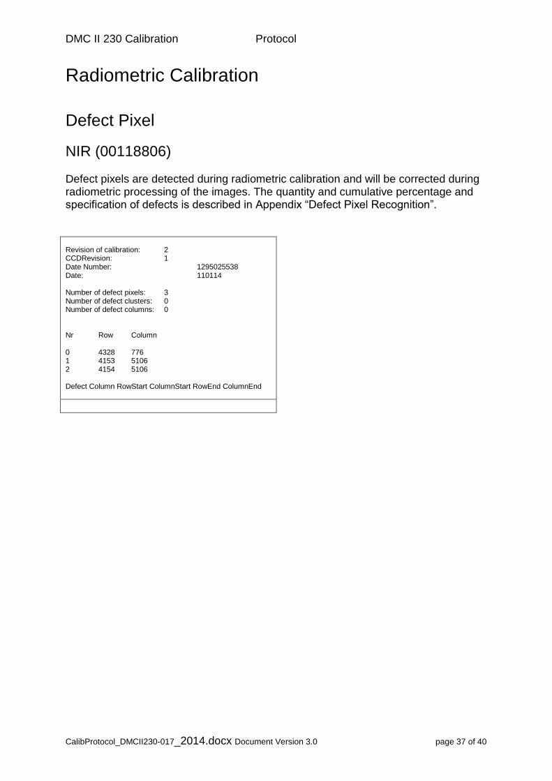
Radiometric Calibration
Defect Pixel
NIR (00118806) Defect pixels are detected during radiometric calibration and will be corrected during radiometric processing of the images. The quantity and cumulative percentage and specification of defects is described in Appendix “Defect Pixel Recognition”. Revision of calibration: 2 CCDRevision: 1 Date Number: 1295025538 Date: 110114 Number of defect pixels: 3 Number of defect clusters: 0 Number of defect columns: 0 Nr Row Column 0 4328 776 1 4153 5106 2 4154 5106 Defect Column RowStart ColumnStart RowEnd ColumnEnd
DMC II 230 Calibration Protocol
CalibProtocol_DMCII230-017_2014.docx Document Version 3.0 page 38 of 40
Sensor Geometric Accuracy
Large area CCD imagers are composed (stitched) from several blocks. Stitching on wafer with semiconductor lithographic equipment results in geometric accuracy better than 0.1µm ( Stoldt, H. (2010 ). Therefore the geometric accuracy of individual pixels within a block can be assumed as better or equal the stitching accuracy.
DMC II 230 Calibration Protocol
CalibProtocol_DMCII230-017_2014.docx Document Version 3.0 page 39 of 40
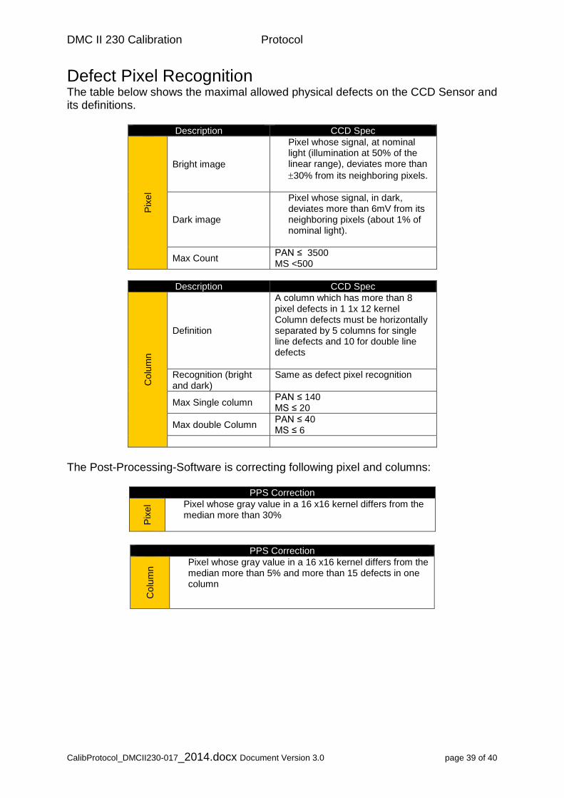
Defect Pixel Recognition The table below shows the maximal allowed physical defects on the CCD Sensor and its definitions.
Description CCD Spec
Pix
el
Bright image
Pixel whose signal, at nominal light (illumination at 50% of the linear range), deviates more than
30% from its neighboring pixels.
Dark image
Pixel whose signal, in dark, deviates more than 6mV from its neighboring pixels (about 1% of nominal light).
Max Count PAN ≤ 3500 MS <500
Description CCD Spec
Colu
mn
Definition
A column which has more than 8 pixel defects in 1 1x 12 kernel Column defects must be horizontally separated by 5 columns for single line defects and 10 for double line defects
Recognition (bright and dark)
Same as defect pixel recognition
Max Single column PAN ≤ 140 MS ≤ 20
Max double Column PAN ≤ 40 MS ≤ 6
The Post-Processing-Software is correcting following pixel and columns:
PPS Correction
Pix
el Pixel whose gray value in a 16 x16 kernel differs from the
median more than 30%
PPS Correction
Colu
mn
Pixel whose gray value in a 16 x16 kernel differs from the median more than 5% and more than 15 defects in one column
DMC II 230 Calibration Protocol
CalibProtocol_DMCII230-017_2014.docx Document Version 3.0 page 40 of 40
Bibliography
Brown D. C. Close-Range Camera Calibration, Photogrammetric Engineering 37(8) 1971 Dörstel C., Jacobsen K., Stallmann D. (2003): DMC – Photogrammetric accuracy – Calibration aspects and Generation of synthetic DMC images, Eds. M. Baltsavias / A.Grün, Optical 3D Sensor Workshop, Zürich Fraser C., Digital Camera sel-f calibration. ISPRS Journal of Photogrammetry and Remote Sensing, (997, 5284): 149-159 Zeitler W., Dörstel C., Jacobsen K. (2002): Geometric calibration of the DMC: Method and Results, Proceedings ASPRS, Denver, USA. Ryan R., Pagnutti M. (2009): Enhanced Absolute and Relative Radiometric Calibration for Digital Aerial Cameras, in: Fritsch D. (Ed.), Photogrammetric Week 2009, Wichmann-Verlag, pp. 81-90. Doering D., Hildebrand J., Diete N. (2009): Advantages of customized optical design for aerial survey cameras, in: Fritsch D. (Ed.), Photogrammetric Week 2009, Wichmann-Verlag, pp. 69-80. Stoldt, H. (2010): DALSA Ultra large CCD technology Customized for Aerial Photogrammetry. At: ASPRS 2010, San Diego, USA, p. 15.