Embed Size (px)
Citation preview

*Corresponding author email: [email protected] GroupSymbiosis Group
Symbiosis www.symbiosisonline.org www.symbiosisonlinepublishing.com
Camera Based Localization of a Smartphone in a VehicleVamsi Paruchuri*, Aravind Kumar
Department of Computer Science, University of Central Arkansas, Conway, AR 720.
Journal of Computer Science Applications and Information Technology Open AccessResearch article
and Prevention (CDC), in year 2011 alone, 3,331 people were killed in accidents involving a distracted driver [18]. CDC also reports that around 31% of the drivers were reported to have used the text message or email features while driving. Combining these data, around 1,033 people were killed by texting and driving.
Even without the statistical data, it is evident that cell phone usage while driving is a major distraction. The consequences of distracted driving are well recognized. In United States, as of March 2016, 14 states have laws that ban driving while talking on a handheld cell phone, and Forty-six States, ban text messaging for all drivers [2].
Detecting vehicular movement is straightforward but ascertaining whether the user is indeed the driver is a complex problem. The fundamental problem of distinguishing between a driver and passenger using a mobile phone is the critical input to enable numerous safeties and interface enhancements. As in prior work, we seek to determine the in-vehicle location of the phone and use that as a heuristic to determine whether the phone is used by the driver or passenger. It uses a fundamentally different sensing approach to determine this location.
Determining the movement of a vehicle is simple in that the speed can be calculated by using data from the GPS. Based on the speed determined, after a preselected speed, the cell phone can be disabled; or at least functions such as texting, games, can be disabled. However, determining if the user of the cell phone is indeed the driver is a challenging step. For an application that limits Smartphone functionality for a driver to execute successfully, the cell phone should be disabled only when it is used by a person driving a vehicle.
Determining position of a Smartphone in a vehicle can enable and provide context for numerous interesting in-vehicle applications, including driver distraction prevention, driving behaviour estimation, in-vehicle services customization, etc. However, most of the existing work on in-vehicle positioning relies on special infrastructures, such as the stereo, cigarette lighter adapter or OBD (on-board diagnostic) adapter. In this paper, we propose an infrastructure-free, in-vehicle positioning system via smart phones. Our methodology uses only embedded camera in smart phones to determine the phones’ seat-level locations in a vehicle.
AbstractDistracted driving is any activity that could divert a person’s
attention away from the primary task of driving. All distractions endanger driver, passenger, and bystander safety. Cell phone usage while driving is a major distraction. Multiple solutions have been proposed on limiting smart phone functionality when being used by a driver. However, it remains challenge to detect if it is indeed the driver using the Smartphone.
The objective of this paper is to address the fundamental problem of distinguishing the driver from passengers, non-intrusively, i.e., enabling driver phone detection without relying on any particular situations, events, and dedicated hardware devices. We rely on the ubiquitous camera feature of cell phones to determine the position of the camera (hence, cell phone) in a vehicle. Compared with the state-of-the-art solutions, a key property of our solution is our system only utilizes the camera functionality of a Smartphone. Images captured from a camera are compared with reference images by applying image registration methods, making a comparison. Through extensive experimental results and analysis, we demonstrate that our methodology can provide accurate localization of a Smartphone, thus effectively distinguishing driver from passengers.
Received: October 10, 2016; Accepted: October 14, 2016; Published: November 04, 2016
*Corresponding author: Vamsi Paruchuri, Department of Computer Science, University of Central Arkansas, Conway, AR 720, E-mail: [email protected]
IntroductionDistracted driving is any activity that could divert a person’s
attention away from the primary task of driving [1]. All distractions endanger driver, passenger, and bystander safety. Some types of distractions are texting, using a cell phone or Smartphone, eating and drinking, talking to passengers, grooming, reading, including maps, and using a navigation system. However, because text messaging requires visual, manual, and cognitive attention from the driver, it is by far the most alarming distraction [1]. In year 2014 alone over three thousand people were killed, and 431,000 were injured in motor vehicle crashes involving distracted drivers [1]. Drivers in their 20s are 23 percent of drivers in all fatal crashes, but are 27 percent of the distracted drivers and 38 percent of the distracted drivers who were using cell phones in fatal crashes [2].
For a very long time, the acronym “dbc” or “DBC” usually meant a delicious serving of Death By Chocolate. But in recent years, thanks to the reckless use of cell phones by people while driving, you could as well change the expansion to Death By Cell Phone. According to a survey by the Centre for Disease Control

Page 2 of 8Citation: Paruchuri V, Kumar A (2016) Camera Based Localization of a Smartphone in a Vehicle. J Comp Sci Appl Inform Technol. 1(1): 8. DOI: http://dx.doi.org/10.15226/2474-9257/1/1/00104
Camera Based Localization of a Smartphone in a VehicleCopyright:
© 2016 Paruchuri and Kumar
acceleration varies depending on the position in the car. This is referred to as low-infrastructure approach since it can be retrofitted in existing cars by plugging in a small OBD-II or cigarette light adapter.
TEXIVE [15] achieves the goal of distinguishing drivers and passengers, and detecting texting operations during driving utilizing irregularities and rich micro-movements of users.
The paper [17] attempts to answer the question “is it possible using only mobile phone’s embedded accelerometer to detect changes in gait pattern caused by changed attention level due to interaction with mobile device like reading on-screen text”. Two different approaches based on gait phase and gait velocity were tested on recorded data in batch mode with more promising one implemented in real-time manner.
In iLoc [16], in-vehicle smart phones automatically collect data during certain kinds of events and cooperatively determine the relative left/right and front/back locations. iLoc is also tolerant to noisy data and possible sensor errors.
Using sensor data from the Smartphone is commonplace to determine the position of the cell phone user. Our idea was to capture images from the back facing camera of the cell phone and compare them with reference images, thus finding the position of the camera and the driver. A literature review provided no evidence of such a method tried before in this context and was given a go ahead to be implemented as a proof of concept. A manual comparison of pictures would have been very trivial but making the comparison process automated involved challenges: the comparison process itself and metrics to determine the position. These topics are discussed in sections 3, 4, 5 and 6 respectively.
Detecting Camera PositionThe central idea of the proposed methodology is to let the
embedded camera capture images periodically and use these images to provide context and / or position of the Smartphone.
Image Registration
When a human compares images, the brain extracts information such as: the similarity between the images, color, intensity, distance between the images, the difference in angle between them and so on. When this process is done electronically, the images are overlapped and various pieces of information are collected. This process is termed as Image registration [5] and falls under the field of computer vision. Image registration techniques have been used successfully in areas such as remote sensing, medical image analysis (comparing CT scans, MRI scans), astrophotography and of course, computer vision. Hence, image registration became the obvious choice to be used in this project.
At first glance, image registration seems like an easy task to perform, how hard could it be to overlay images and extract information? It is challenging. Challenges are introduced due to the nature of image acquisition. Some major challenges are:
1. The different angles at which the reference image and
.Rest of the paper is organized as follows: Section II surveys
related works. Section III provides necessary background information on image registration and using these techniques to position the camera. Section IV details the experimental setup. In Section V, we extensively detail the results and analysis. Finally, Section VI provides concluding remarks and future work.
Related workFor an application such as the one mentioned in the previous
section to execute successfully, the cell phone should be disabled only when it is used by a person driving a vehicle. Determining the movement of a vehicle is simple in that the speed can be calculated by using data from the GPS. Based on the speed determined, after a preselected speed, the cell phone can be disabled; or at least functions such as texting, games, etc. can be disabled. However, determining if the user of the cell phone is indeed the driver is a challenging step.
Previously, researchers proposed solutions to detect when a call was being made / answered. However, speaking over the phone is the least of our worries in the present day. In case of phone calls, we can expect the driver to at least keep his eyes on the road. But, with features such as texting and games being commonplace on phones nowadays, they are proving to be more dangerous and distracting since the driver would have to remove his eyes off the road. To determine this kind of usage, many concepts have been proposed. Some of the concepts include developing an approach where the caller is notified of the recipient’s situation; i.e. whether the recipient can reply to the call, or should the call be transferred to voicemail or respond with an automatic message [20]. Papers [3] and [4] proposed to use the sensors in a Smartphone such as gyroscopes and accelerometers to detect the position of the camera phone thus determining the position of the person using it.
The problem of distinguishing between a driver and passenger using a mobile phone is widely studied in literature. A fusion of embedded sensors in a smart phone (accelerometers, gyroscopes, microphones, and magnetic sensors) is used in [11] to distinguish the driver from passengers. This system utilizes naturally arising driver motions, i.e., sitting down sideways, closing the vehicle door, and starting the vehicle, to determine whether the user enters the vehicle from left or right and whether the user is seated in the front or rear seats.
A detection system leveraging the car stereo infrastructure, in particular, the speakers and Bluetooth network is proposed and studied in [12]. This acoustic approach has the phone send a series of customized high frequency beeps via the car stereo.
DriveSafe [13] applies computer vision and pattern recognition techniques on the phone to detect the most commonly occurring inattentive driving behaviours divided into two main groups: drowsiness and distractions. The driver’s iPhone must be placed on the windshield, just below the rear view mirror and aligned with the relevant axes of the vehicle. The app uses the information obtained from some inbuilt iPhone sensors.
In [14], the authors exploit the insight that the centripetal

Page 3 of 8Citation: Paruchuri V, Kumar A (2016) Camera Based Localization of a Smartphone in a Vehicle. J Comp Sci Appl Inform Technol. 1(1): 8. DOI: http://dx.doi.org/10.15226/2474-9257/1/1/00104
Camera Based Localization of a Smartphone in a VehicleCopyright:
© 2016 Paruchuri and Kumar
the sensed image (the captured image which is compared with the reference image) are acquired.
2. The times of capturing the reference and sensed images causing the scene to change.
3. Illumination/lighting difference between the reference and sensed images.
4. Noise and the types of sensors used.
Because of the above cases, one particular registration technique cannot be used universally for all problems. The techniques used have to be customized based on the type of images at hand. The next section discusses the images registration steps and the techniques that were used in this paper.
Image Registration Techniques
Once the sensed image has been acquired, depending on the quality of the image, pre-processing and post-processing might be required either side of the registration process [5]. This paper considers these processes as the secondary steps of registration and does not discuss them in detail. The primary steps involved in Image registration can be generalized as follows:
i. Feature detection and description
ii. Feature matching
iii. Geometric transformation estimation
i. Feature detection and description: As the name states, this step involves detecting attributes or features from the reference and sensed images. The features are detected for both images separately, i.e. the steps mentioned in this subsection and the next subsection is repeated for both the reference and sensed image. Feature detection methods can be broadly divided into two types: area based and feature based. The area based methods do not attempt to detect any features explicitly. Instead, they try to directly match images based on methods with a pre-selected window function, usually a rectangular window. Area based methods are disadvantageous since they are not effective on complex transformations because the rectangular window does not operate effectively. Since our images involved more complex transformations than translation the feature based methods were explored.
Feature based methods are best applicable when salient features are present in an image. These features can include distinctive regions, lines, edges, etc. Feature based methods are more robust against transformations and the features are usually invariant to changes. Some of the type of feature based methods are SIFT, SURF, HOG, Harris, and BRISK. After reading up on the different methods, the Speeded Up Robust Features (SURF) detector and descriptor [10], which is based on the blob detector was chosen as the method to be implemented. A brief working of the SURF detector and descriptor is as explained as follows.
The first step is to detect the interest points in an image. Interest points can be edges, corners, blobs, etc. SURF uses a blob detection scheme. A blob is region of an image having some constant or varying properties in a given region. Usually they
are color and contrast but SURF uses only contrast information which aids in making the descriptor more efficient. To detect interest points, SURF uses a second order Hessian second order partial derivative. This is helpful in identifying the interest point; i.e. a point with a zero derivative/partial derivative and is also accurate. Next, second-order Gaussian is calculated using integral images. These filter responses are normalized in size and follow a Frobenius norm which is useful in the next step. Finding interest points at a single scale is not conducive. Instead, to increase accuracy and obtain proper interest points, the image has to be scaled. The scale of the image is increased (since it follows a Frobenius norm), not by increase the image itself but by using a box-filter which improves the computational efficiency. Unlike up-scaling, downscaling doesn’t create aliasing. Based on the results of the scaling process, correct interest points are detected.
The second step is to perform interest point description. When interest points are detected, the number of points is usually huge in size and most of these points do not provide useful information. A descriptor chooses the strongest among these interest points and a feature vector is created. The SURF descriptor is based on Haar wavelets. Haar wavelets are calculated for the x and y axes and are represented as points in space. These wavelets are summed up and a vector is formed. The vector with the longest sliding window is the interest point. The descriptor is further strengthened by constructing square regions around each window and calculating the Haar wavelets, which again generates a feature vector. Finally, the contrast between the interest point and the image regions surrounding it is compared. Only those with similar contrasts are retained as the final interest points.
ii. Feature matching: Feature matching is conducted after detecting the interest points. In this step, the interest points from the reference image and the interest points from the sensed image are matched. From the previous subsection, we have seen that interest points are represented as feature vectors. In the feature matching step, the feature vectors of the reference and sensed images are matched. If the two feature vectors contain a high amount of same or similar information, they are considered as corresponding points.
iii. Geometric Transformation Estimation: The final process in image registration is to perform transformations on the sensed images. This process is necessary so that the reference and sensed images can be overlaid over each other and the difference between them can be calculated thus obtaining a result as to whether the two images are same or not. Some of the common types of translations are translation, reflection, rotation, scaling and shear. Images may contain a single transformation or may be a combination of one or more transformations. The transformation to be applied is usually selected based on the previous knowledge. For our experiment, we found out that homography or projective transformation was the best suited method to be applied. The projective transformation was chosen over another similar transformation; affine transformation because of the non-linear nature of the images captured. In addition, during the initial stages of the experiment, the

Page 4 of 8Citation: Paruchuri V, Kumar A (2016) Camera Based Localization of a Smartphone in a Vehicle. J Comp Sci Appl Inform Technol. 1(1): 8. DOI: http://dx.doi.org/10.15226/2474-9257/1/1/00104
Camera Based Localization of a Smartphone in a VehicleCopyright:
© 2016 Paruchuri and Kumar
projective transformation was more robust and provided better results than when the affine transformation was used.
Camera Position Detection
As mentioned earlier 3, image registration is usually used in the medical or remote sensing fields. A human is present to compare the reference and sensed images and extract the necessary information. However, in our case, we automate the comparison. Hence, after registration process, the scaling factor and angle between the referenced and sensed image were calculated to find the position of the camera. Their implementation is mentioned later in the paper.
Experimental SetupThe first step of the experiment was to calculate the distances
between objects inside the car. These distances were used in determining the position of the camera when the sensed image was captured. A 1999 Toyota Avalon was used for the experiments. The following distances were calculated (an error margin of +/- 5 cm was assumed in each case):
1. Distance between the driver-side dashboard and the driver’s seat (at its farthest position from the dashboard, with the back-rest in upright position): 75 cm.
2. Distance between the front passenger-side dashboard and the passenger’s seat (at its farthest position from the dashboard, with the back-rest in upright position): 80 cm.
3. Width of the car (from the left side interior of the car to the right side interior): 180cm
4. Distance between the dashboard and the back passenger’s seat: 145 cm.
5. Diagonal distance from the steering wheel to the front passenger seat: 185 cm. (This value was necessary to calculate the position of images captured from the front passenger seat)
In the next step, the reference images were captured. An iPhone 4 running iOS 7.1 was used. Pictures of the entire front of the car (the dashboard section) on the driver and passenger side were captured. The distance from which the reference images were captured, the position and the number of reference images were set based on trial and error. Each image was shot by placing the camera right next its previous position. All images were captured in such a way that the camera remained parallel to the dashboard. The images were captured from a distance of 75 to 80 cm away from the dashboard. A total of 19 reference images were captured. For the sake of the experiment, reference images were divided into three groups; those captured from the driver’s side, the middle of the car and the passenger side.
In the next step, the real time images for position detection were captured. There were no “best positions” to capture sensed images since every person has different ways of holding their phone in the hand. With this in mind, 38 sensed images were captured in total. These images were captured from different positions such as the driver’s seat, the front passenger’s seat
and the rear seats. Since the idea of the project was to detect where the camera is positioned based on the sensed image and to make the project fool-proof, different images were replicated from different positions; i.e. the driver’s side area was captured from the rear and front passenger’s seat, the front passenger area was captured from the driver’s side. When the driver’s side was replicated from the rear passenger seats, digital zoom was applied to give a feeling that the image was captured from the driver’s area. One important thing to be noted here is that the sensed images were captured in such a way that the user could see his screen; i.e. phone was held facing the user at natural angles.
For the experiment, different tools such as Java, OpenCV and Octave were considered. But because of the high complexity of implementation and lack of appropriate libraries, MATLAB was chosen as the tool to be used. We mentioned about digital zoom in the previous paragraph. This is a crucial element but there was no way to extract this piece of information from MATLAB. Hence the website exifdata.com was used to extract the zoom information. A sensed image was compared with each reference image from the beginning and the comparison stopped when the sensed image registered closely with the reference image. Next, the angle difference and the distance between the reference and sensed images using the zoom data found. If both were found to be correct, the experiment was conducted on the next sensed image. Zoom data is usually set to 1 if no digital zoom information is available. Else, the extracted zoom data is used.
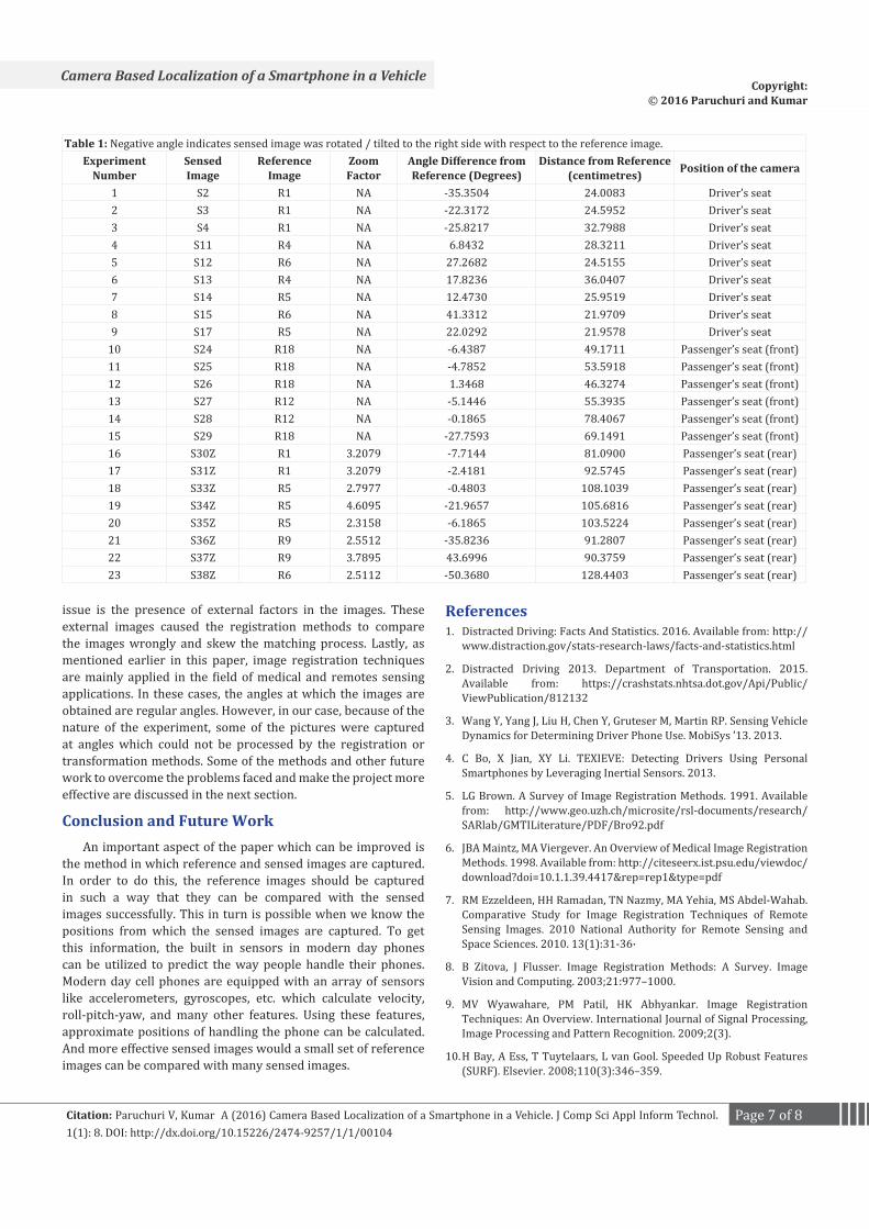
Experimental Results and Performance AnalysisTable 1 provided below consists of all the results from
the experiment. We noticed that we have 23 entries in the ‘Experiment Number’ section. This means that 23 out of the 38 sensed images were registered successfully. Out of the 23 registered successfully, all of them calculated the correct angle and distance thus finding the correct driver’s position. This gives us an accuracy of 60.5263%. The table can be analyzed by dividing it into three sections; experiments 1 through 9 which contain data from the sensed images captured from the driver’s section, experiments 10 to 15 which contain data from the sensed images captured from the passenger’s seat and experiments 16 to 23 which contain data from the sensed images captured from the rear seat of the passenger with zoom activated.
From experiments 1 through 9 we observe that images captured from the driver’s position is constantly between 20 cm to 40 cm from the dashboard. Since the average position of the driver was 30 cm over nine experiments, this can be assumed as the regular distance between the driver and the dashboard. Also, we had noted in the previous section that the distance between the steering wheel and driver’s seat was around 75 cm. Hence, by considering the empty space between the steering and the driver and the space between the drivers’s back, back-rest included we can conclude that the image was indeed taken from the driver’s seat.
From experiments 10 to 15 we observe that the images were captured from the passenger’s seat. This can be clearly indicated

Page 5 of 8Citation: Paruchuri V, Kumar A (2016) Camera Based Localization of a Smartphone in a Vehicle. J Comp Sci Appl Inform Technol. 1(1): 8. DOI: http://dx.doi.org/10.15226/2474-9257/1/1/00104
Camera Based Localization of a Smartphone in a VehicleCopyright:
© 2016 Paruchuri and Kumar
by the increase in the distance. Since all the images were captured from the passenger’s seat, the sensed images were now more diagonally positioned to the reference images. This explains the increase in length. We find that the average distance across the experiment is 60 cm which turned out to be the case when physically measured.
Lastly, from experiments 16 to 23 we observe that the images were captured from the rear passenger’s seat. This can be concluded from the distances calculated and by the presence of a zoom factor. We notice that the distances are more than 80 cm from the dashboard. Though the distance can be mistaken to point to a position in the front passenger’s seat, the presence of the zoom factor clearly indicates otherwise.
For our analysis, we choose three experiments from the table: 5, 15 and 19. They represent images captured from the driver’s seat, the passenger’s seat and from the rear passenger seat with digital zoom.
The results from experiment 5 are shown by Fig.1 through Fig. 5. From Table 1, the position is correctly determined. Since the sensed image is tilted/rotated to the left side with respect to the reference, we obtain positive angle of 27.282 degrees and a distance of 24.5155 cm. which can be deduced by looking at Fig. 1.contains two images compared side by side; to the left is the reference image and to the right is the sensed image. From the naked eye observe that the image is taken from the driver’s side in the car.
Fig. 2 shows the matching stage of the experiment where the SURF points from the reference image and sensed image are compared. The yellow lines connect the SURF points on the reference and sensed images. The green ‘+’ symbols indicated the points on the reference image and the red circles indicated the points in the sensed image.
Though Fig. 3 looks similar to Fig. 2, if closely observed we notice that the number of yellow lines is less compared to Fig. 2. This is because, the image is displayed after the curve fitting process is completed and only inliers’ points or the points that fit the curve are considered. Going back to Fig. 2 we notice that the gear lever in one image is wrongly matched with the steering wheel in the other image. Such points or outlier points are eliminated.
Fig. 4 describes the sensed image after the transformation is applied. We notice that it is significantly transformed from how it looked in the right side of Fig. 1.
Finally, in Fig. 5 we notice that the reference and the transformed sensed image are overlaid. The reference image is green in color and the sensed image is a shade of pink. On observing closely, we notice that some areas which overlap perfectly are actually gray in color; the stereo system. From the table we observe that the sensed image in experiment 5 was captured from the driver’s seat.
Next we look at the figures from experiment 15. Fig. 6 and Fig. 7 represent this case. Only the images comparing the reference
Figure 1: Results from experiment 5 where the position is correctly determined.
Figure 2: Matching reference image and sensed image.
Figure 3: Results from curve fitting process.
and sensed image before and after transformation are displayed. From experiment 15, we obtain values of -27.7593 for the angle and a distance of 69.1491 cm for the distance. And the position is detected correctly as having been taken from the passenger’s seat. We notice in Fig. 6 that the image has been captured from the passenger side of the car.
Finally, we look at the figures from experiment 19. Fig. 8 and Fig. 9 represent this case. We notice in Fig. 8 that the sensed image

Page 6 of 8Citation: Paruchuri V, Kumar A (2016) Camera Based Localization of a Smartphone in a Vehicle. J Comp Sci Appl Inform Technol. 1(1): 8. DOI: http://dx.doi.org/10.15226/2474-9257/1/1/00104
Camera Based Localization of a Smartphone in a VehicleCopyright:
© 2016 Paruchuri and Kumar
Figure 4: Sensed image after the transformation.
Figure 5: Sensed image overlaid on referenced image.
Figure 6: Experiment 15 comparison before transformation.
appears as though it has been captured from the driver’s seat. But from experiment 19, we obtain values of -21.9657 for the angle and a distance of 105.6816 cm for the distance. Along with this we also have a zoom factor of 4.6095. The position is detected correctly as having been taken from the rear passenger’s seat.
One observation we make from Table 1 is the accuracy. We notice that 15 out of the 38 sensed images were not
registered correctly. Below we will look at some of the reasons or challenges due to which the efficiency decreased. One of the main requirements for the feature based detectors to work is the presence of distinct points from which the features can be extracted. In many of the images, especially involving the passenger side dashboard, the methods could not find enough points to extract. This caused an error in the code and such sensed images could not be compared registered. The other
Figure 7: Experiment 15 comparison after transformation.
Figure 8: Experiment 19 comparison before transformation.
Figure 9: Experiment 19 comparison after transformation.
Page 7 of 8Citation: Paruchuri V, Kumar A (2016) Camera Based Localization of a Smartphone in a Vehicle. J Comp Sci Appl Inform Technol. 1(1): 8. DOI: http://dx.doi.org/10.15226/2474-9257/1/1/00104
Camera Based Localization of a Smartphone in a VehicleCopyright:
© 2016 Paruchuri and Kumar
Table 1: Negative angle indicates sensed image was rotated / tilted to the right side with respect to the reference image.Experiment
NumberSensed Image
Reference Image
Zoom Factor
Angle Difference from Reference (Degrees)
Distance from Reference (centimetres) Position of the camera
1 S2 R1 NA -35.3504 24.0083 Driver’s seat2 S3 R1 NA -22.3172 24.5952 Driver’s seat3 S4 R1 NA -25.8217 32.7988 Driver’s seat4 S11 R4 NA 6.8432 28.3211 Driver’s seat5 S12 R6 NA 27.2682 24.5155 Driver’s seat6 S13 R4 NA 17.8236 36.0407 Driver’s seat7 S14 R5 NA 12.4730 25.9519 Driver’s seat8 S15 R6 NA 41.3312 21.9709 Driver’s seat9 S17 R5 NA 22.0292 21.9578 Driver’s seat
10 S24 R18 NA -6.4387 49.1711 Passenger’s seat (front)11 S25 R18 NA -4.7852 53.5918 Passenger’s seat (front)12 S26 R18 NA 1.3468 46.3274 Passenger’s seat (front)13 S27 R12 NA -5.1446 55.3935 Passenger’s seat (front)14 S28 R12 NA -0.1865 78.4067 Passenger’s seat (front)15 S29 R18 NA -27.7593 69.1491 Passenger’s seat (front)16 S30Z R1 3.2079 -7.7144 81.0900 Passenger’s seat (rear)17 S31Z R1 3.2079 -2.4181 92.5745 Passenger’s seat (rear)18 S33Z R5 2.7977 -0.4803 108.1039 Passenger’s seat (rear)19 S34Z R5 4.6095 -21.9657 105.6816 Passenger’s seat (rear)20 S35Z R5 2.3158 -6.1865 103.5224 Passenger’s seat (rear)21 S36Z R9 2.5512 -35.8236 91.2807 Passenger’s seat (rear)22 S37Z R9 3.7895 43.6996 90.3759 Passenger’s seat (rear)23 S38Z R6 2.5112 -50.3680 128.4403 Passenger’s seat (rear)
issue is the presence of external factors in the images. These external images caused the registration methods to compare the images wrongly and skew the matching process. Lastly, as mentioned earlier in this paper, image registration techniques are mainly applied in the field of medical and remotes sensing applications. In these cases, the angles at which the images are obtained are regular angles. However, in our case, because of the nature of the experiment, some of the pictures were captured at angles which could not be processed by the registration or transformation methods. Some of the methods and other future work to overcome the problems faced and make the project more effective are discussed in the next section.
Conclusion and Future WorkAn important aspect of the paper which can be improved is
the method in which reference and sensed images are captured. In order to do this, the reference images should be captured in such a way that they can be compared with the sensed images successfully. This in turn is possible when we know the positions from which the sensed images are captured. To get this information, the built in sensors in modern day phones can be utilized to predict the way people handle their phones. Modern day cell phones are equipped with an array of sensors like accelerometers, gyroscopes, etc. which calculate velocity, roll-pitch-yaw, and many other features. Using these features, approximate positions of handling the phone can be calculated. And more effective sensed images would a small set of reference images can be compared with many sensed images.
References1. Distracted Driving: Facts And Statistics. 2016. Available from: http://
www.distraction.gov/stats-research-laws/facts-and-statistics.html
2. Distracted Driving 2013. Department of Transportation. 2015. Available from: https://crashstats.nhtsa.dot.gov/Api/Public/ViewPublication/812132
3. Wang Y, Yang J, Liu H, Chen Y, Gruteser M, Martin RP. Sensing Vehicle Dynamics for Determining Driver Phone Use. MobiSys ’13. 2013.
4. C Bo, X Jian, XY Li. TEXIEVE: Detecting Drivers Using Personal Smartphones by Leveraging Inertial Sensors. 2013.
5. LG Brown. A Survey of Image Registration Methods. 1991. Available from: http://www.geo.uzh.ch/microsite/rsl-documents/research/SARlab/GMTILiterature/PDF/Bro92.pdf
6. JBA Maintz, MA Viergever. An Overview of Medical Image Registration Methods. 1998. Available from: http://citeseerx.ist.psu.edu/viewdoc/download?doi=10.1.1.39.4417&rep=rep1&type=pdf
7. RM Ezzeldeen, HH Ramadan, TN Nazmy, MA Yehia, MS Abdel-Wahab. Comparative Study for Image Registration Techniques of Remote Sensing Images. 2010 National Authority for Remote Sensing and Space Sciences. 2010. 13(1):31-36·
8. B Zitova, J Flusser. Image Registration Methods: A Survey. Image Vision and Computing. 2003;21:977–1000.
9. MV Wyawahare, PM Patil, HK Abhyankar. Image Registration Techniques: An Overview. International Journal of Signal Processing, Image Processing and Pattern Recognition. 2009;2(3).
10. H Bay, A Ess, T Tuytelaars, L van Gool. Speeded Up Robust Features (SURF). Elsevier. 2008;110(3):346–359.

Page 8 of 8Citation: Paruchuri V, Kumar A (2016) Camera Based Localization of a Smartphone in a Vehicle. J Comp Sci Appl Inform Technol. 1(1): 8. DOI: http://dx.doi.org/10.15226/2474-9257/1/1/00104
Camera Based Localization of a Smartphone in a VehicleCopyright:
© 2016 Paruchuri and Kumar
11. Homin P, DaeHan A, Myounggyu W, Sang HS, Taejoon P. Poster: Are you driving? non-intrusive driver detection using built-in smartphone sensors. MobiCom ‘14 In Proceedings of the 20th annual international conference on Mobile computing and networking . 2014:397-400. doi: 10.1145/2639108.2642896.
12. Yang J, Simon S, Gayathri C, Tam V, Hongbo L, Nicolae C, et al., Sensing Driver Phone Use with Acoustic Ranging through Car Speaker. IEEE Transactions on Mobile Computing. 2012;11(9).
13. L. M. Bergasa, D. Almería, J. Almazán, J. J. Yebes, R. Arroyo. DriveSafe: an App for Alerting Inattentive Drivers and Scoring Driving Behaviors. IEEE Intelligent Vehicles Symposium. 2014;240–245. doi: 10.1109/IVS.2014.685646.
14. Yan Wang, Jie Yang, Hongbo Liu, Yingying Chen, Marco Gruteser, Richard P. Martin. Sensing vehicle dynamics for determining driver phone use. MobiSys ‘13 In Proceeding of the 11th annual international conference on Mobile systems, applications, and services. 2013:41-54. doi:10.1145/2462456.2464447.
15. Cheng Bo, Xuesi Jian, Xiang-Yang Li, Xufei Mao, Yu Wang, and Fan Li.. You’re driving and texting: detecting drivers using personal smart
phones by leveraging inertial sensors. MobiCom ‘13 In Proceedings of the 19th annual international conference on Mobile computing & networking. 2013.
16. Zongjian He, Jiannong Cao, Xuefeng Liu and Shaojie Tang. Who Sits Where? Infrastructure-Free In-Vehicle Cooperative Positioning via Smartphones. Sensors. 2014;14(7):11605-11628. doi:10.3390/s140711605.
17. Music J, Stancic I, Zanchi V. Is it possible to detect mobile phone user’s attention based on accelerometer measurment of gait pattern? IEEE Symposium on Computers and Communications (ISCC). 2013
18. Distracted Driving, Injury Prevention & Control: Motor Vehicle Safety, Centers for Disease Control and Prevention. 2016. Available from: http://www.cdc.gov/motorvehiclesafety/distracted_driving/
19. Yang J, Sidhom S, Chandrasekaran G, Vu T, Liu H, Cecan N, et al. Detecting Driver Phone Use Leveraging Car Speakers. MobiCom ’11. 2011.
20. Lindquist J, Hong J. Undistracted Driving: A Mobile Phone That Doesn’t Distract. HotMobile ’11. 2011.