Embed Size (px)
Citation preview
Camera Axe 5 User Manual
Document Version: 5.4.0
February 28, 2013
Authors: Maurice Ribble and Andrew Morgan

Introduction
Differences between Camera Axe 5 and Camera Axe 5 Shield
Hardware
Display
Power Switch
Activate Button
Select Button
Menu Button
Arrow/Cursor Buttons
Camera Flash Buttons
Camera/Flash LEDs
Camera/Flash Ports
Sensor Ports
USB Port
Menus
Enabling or Disabling Menus
Advanced Sensor Menu
Projectile Menu
Valve Menu
Intervalometer Menu
General Settings Menu
Other Menus
Gravity Menu
IR Remote Menu
Stacker Menu
Panorama Menu
Jog Menu
Rollercoaster Menu
Dongle Menu
Sensors
Light Sensor
Laser Sensor
Microphone Sensor
Projectile Sensor
Valve Sensor
Photogate Sensor
Motion/Distance Sensor
Camera Shutter Sync Sensor
Clip Sensor
Multi-Flash Board
Introduction
The Camera Axe is a tool for photographers to trigger cameras or flashes based on signals from
various inputs. It is useful for catching phenomena that happen too quickly for human reflexes, like
photographing a popping balloon, a shooting bullet, or a milk droplet splash. Other uses can be to
catch things photographers don't want to wait around for like birds flying to a bird feeder or
surveillance of people walking down a hallway. It can also run an advanced intervalometer or drive
external motors. The possibilities are endless. This document describes the operation of the Camera
Axe 5 and the Camera Axe 5 Shield hardware and menus. This manual was written for the Camera
Axe 5.4 software. Other versions of the software function similarly but there will be some minor
differences in operation.
For those who like learning from videos there is a large (and growing) collection of videos about the
Camera Axe at http://www.techphotoblog.com.
Differences between Camera Axe 5 and Camera Axe 5 Shield
The Camera Axe 5 is a fully assembled and tested device. Units shipped after July 1, 2012 use 6 AA
batteries or can be powered from the USB cable, but the USB cable does not charge the batteries. It
is suggested if running this version of the Camera Axe off the USB cable to turn the power switch off
(it will stay on and run completely off the power provided from the USB cable). Units shipped before
July 1, 2012 come with a rechargeable battery and the USB cable does the recharging. The rest
applies to both types of the Camera Axe 5. Use the USB cable to upgrade the firmware. It also
comes with a custom designed enclosure. The extra third LED on this board is used to indicate if
power is being provided from the USB cable.
The Camera Axe 5 Shield is a kit that must be soldered together. The user must supply an Arduino
Uno (or compatible) development board and a way to power the device. Since this version gets it’s
power from the Arduino there is no power switch. This version does not come with an enclosure.
This shield version does use the same software and has all the same functionality as the standard
Camera Axe 5 in a much cheaper package for the DIY and Maker crowd.
Hardware
The top of the both versions has a display screen, a number of buttons, a power switch (not on shield
version), and two LEDs. The third LED on standard Camera Axe 5 is used to indicate if power is
coming from the USB port. On the sides are two of plugs to attach the camera(s) and/or flash(s) and
up to two sensors. The standard version also has a USB port used for charging or reprogramming the
Camera Axe. The shield version gets its power from the Arduino board and the Arduino board has a
USB port for programming.
The microcontroller used in the Camera Axe is an ATmega328 with the Arduino bootloader installed.
Arduino is a common open source platform that makes programming microcontrollers like the
Atmega328 very easy. For more information about how to load new version of the Camera Axe
software or to start making your own modifications visit http://www.cameraaxe.com/programming/.
Display
The Camera Axe uses a 2” X 1” LCD capable of displaying 128X64 pixels. This display is
used to provide input capability using the menu functions described below and feedback to the
user.
Power Switch
The shield version has no power switch. To turn the power on/off on the shield version you
can either add a switch between the battery providing power to the Arduino or just unplug
power from the Arduino.
The power switch turns on/off the unit. When the unit is powered on it goes through a startup
sequence. In the startup, the microcontroller input and output pins are set up, the default
values are loaded from the EEPROM and the display is setup. If the Activate button is
depressed during the startup process, the unit will be reset to the factory default values.
The system stores changes to parameters in flash memory so the settings are saved even
when the batteries are removed.
Activate Button
The activate button turns on/off the monitoring of the sensors. When activated, the unit begins
monitoring the sensor status according to the design of the currently shown menu options.
This is known as the photo mode. When in photo mode, the other buttons are ignored except
where noted below in the descriptions of the menus. Pressing the activate button again
deactivates the monitoring and returns the system to the menu mode. In menu mode, the
system parameters can be adjusted as described in the Menu sections below.
The activate button will also turn off the display, to save power, when in the photo mode if the
display is set to turn off in 10 seconds.
If the Activate button is depressed during the startup process, the unit will be reset to the
factory default values.
Select Button
The select button toggles the edit mode on and off. When in edit mode, the value of individual
parameters can be adjusted using the arrow buttons. When not in edit mode, the arrow
buttons move from field to field within the current menu. Only one value can be
selected/changed at a time.
Menu Button
The menu button cycles the display between the different menu options. The various menu
options are described in detail below. Pressing the menu button also deactivates the edit
mode and resets the cursor position to the first item in the next menu.
Arrow/Cursor Buttons
In edit mode, the left and right button moves the cursor to the previous/next digit in the setting
being adjusted.
When the up or down button are pressed in the edit mode, the value at the current cursor
position is raised/lowered. Every time a value is changed on the display, it is written to the
microcontroller’s flash memory so if the power is turned off that value will be remembered.
When not in edit mode, the arrow keys are used to navigate around the display to move from
one menu parameter to another. The currently selected parameter is indicated by a flashing
cursor.
Camera Flash Buttons
There are two buttons by the Camera/Flash ports. These buttons will manually trigger the
Camera or Flash attached to these ports. Beyond being useful as a manual trigger, this is also
nice to test your scene setup to make sure the exposure is correct.
In general, the way the buttons are used is to use the Menu button to toggle to the desired menu
option (described below), then use the Arrow buttons to navigate on the display to the desired setting
to change. Once the cursor is on the setting value, the Select button is pressed to enter the edit
mode. Once in the edit mode the individual values can be adjusted. The up and down Arrow buttons
change the value up/down and the right and left buttons allow selecting the next/previous digit for
numerical values. Once the value is at the desired setting/value, the Select button is pressed again to
exit the edit mode. From here, the Arrow buttons can be used to navigate to another parameter, if
necessary. Once all of the settings have been adjusted as desired, the Activate button is pressed to
enter the photo mode. At this point, the sensors are active and a picture can be taken. When done
taking images, press the Activate button again to re-enter the menu mode and repeat the process.
Camera/Flash LEDs
The LED next to the Camera/Flash 1 and Camera/Flash 2 labels indicate when the device is
triggered. A green color means the focus line is active. A red color means the shutter line is
active. An orange color means both the focus and shutter lines are active. The focus line can
also mean that the camera is being kept in in a ready state if auto focus has been disabled
which will give a shorter shutter lag on most cameras.
Camera/Flash Ports
Two of the 3.5 mm jacks on the side of the Camera Axe are camera/flash ports. These ports
are labeled Camera/Flash 1 and Camera/Flash 2. These ports are used to connect either a
camera or flash to be triggered. The Camera/Flash 1 port is named Device 1 in the menus
and the Camera/Flash 2 port is named Device 2.
The way the Camera Axe triggers cameras and flashes is by allowing current to pass through
and the camera or flash provides the voltage. It works like a switch.
There is a wide range of camera cables and cameras supported by the Camera Axe. Look at
this page for more details on different cameras/cables:
http://www.cameraaxe.com/wiki/index.php?title=CameraCables
There is also a wide range of flash cables supported by the Camera Axe. Look at this page for
more details on using different types of flashes:
http://www.cameraaxe.com/wiki/index.php?title=FlashCables
Sensor Ports
The other two 3.5 mm jacks on the side of the Camera Axe are sensor ports. These ports are
labeled Sensor 1 and Sensor 2. These ports are used to connect a wide variety of sensors to
the Camera Axe. Several of the available sensors are described below.
The 3.5 mm jack for sensors provides power, ground, and access to an analog pin on the
microcontroller. The tip of the 3.5mm plug is +5V, the base of the 3.5 mm plug is ground, and
middle of the 3.5 mm plug is the sensor. Starting with Camera Axe 5 (Camera Axe 4 does not
support this) the power pin can also optionally be configured as another analog data pin which
is useful for some sensors.
There is input protection on the these sensor pins, but to be safe you should not exceed 40mA
of current on any of the sensor pins. There is an optional mode that can be turned on in
software for the tip of the sensor pin that can source up to 100 mA. Also make sure any input
voltages are within the range of 0 to 5 volts.
USB Port
On the standard Camera Axe there is also a USB port. This port is used for programming the
Camera Axe with new firmware and to recharge the internal battery.
On the Camera Axe Shield the USB port is located on the Arduino board. This can be used to
power the Camera Axe shield or to reprogram the board. The Arduino also has a 2.1mm dc
jack that can provide power. It accepts 6-12V DC power.
Menus
The Camera Axe provides several different sets of menu operations as described below. Based on
the pressing of the Activate button, the Camera Axe will either be in the “menu” or “photo” mode.
When the Camera Axe is in the menu mode, the various settings can be adjusted according to the
description below. When the Camera Axe is in photo mode, the unit is monitoring the sensors and is
ready to trigger an image.
NOTE: Except for the settings in the General Settings menu, the settings in each menu are
independent. For example, the settings in the Advanced Sensor menu do not affect the
operation of the Camera Axe when using the Projectile, Valve or Intervalometer menus.
Depending on the menu function, there are two different ways that the Camera Axe reads
sensor values.
Depending on the menu function, there various ways the middle sensor pin works:
● analogRead – This returns an analog value between 0 and 1023 proportional to the sensor
voltage of 0 to 5 volts. The Camera Axe displays values from 0 to 999. This is the slower way
to read the sensor value (still quite fast at 20 microseconds) but it provides the ability to read
the range of values from the sensor. This method is used by the Advanced Sensor menu to
allow triggering on a setting or threshold value.
● digitalRead – This is the fastest way to read the sensor state. It only returns a high (1) or low
(0) value. This method is used by the Projectile and Fast Trigger menus.
● Digital out - In this mode sensor pin acts as a digital output sending 0 or 5V. The maximum
output current is around 30 mA. This mode is used by the valve sensor to trigger to allow the
Camera Axe to trigger the valve.
The tip of the sensor has all the functionality above plus the ability to optionally switch in a larger
current (up to at 100 mA). This larger current is used to power various sensors that may require more
power.
Enabling or Disabling Menus
Starting with version 5.3 of the Camera Axe software there were more menus than could fit into
memory on the microcontroller. To address this issue and to keep the number of menus to a
reasonably small number while giving users the option of enabling more menus a feature was added
to the code to make it very easy for you to turn on or off different menus. You can can see how to
load the latest software on the programming page (http://www.cameraaxe.com/programming/). The
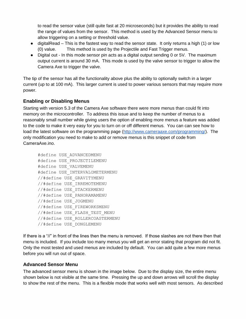
only modification you need to make to add or remove menus is this snippet of code from
CameraAxe.ino.
#define USE_ADVANCEDMENU
#define USE_PROJECTILEMENU
#define USE_VALVEMENU
#define USE_INTERVALOMETERMENU
//#define USE_GRAVITYMENU
//#define USE_IRREMOTEMENU
//#define USE_STACKERMENU
//#define USE_PANORAMAMENU
//#define USE_JOGMENU
//#define USE_FIREWORKSMENU
//#define USE_FLASH_TEST_MENU
//#define USE_ROLLERCOASTERMENU
//#define USE_DONGLEMENU
If there is a “//” in front of the lines then the menu is removed. If those slashes are not there then that
menu is included. If you include too many menus you will get an error stating that program did not fit.
Only the most tested and used menus are included by default. You can add quite a few more menus
before you will run out of space.
Advanced Sensor Menu
The advanced sensor menu is shown in the image below. Due to the display size, the entire menu
shown below is not visible at the same time. Pressing the up and down arrows will scroll the display
to show the rest of the menu. This is a flexible mode that works well with most sensors. As described
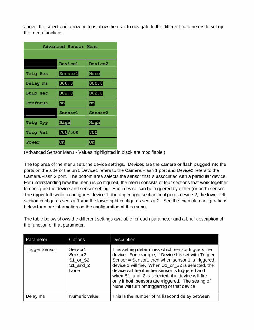
above, the select and arrow buttons allow the user to navigate to the different parameters to set up
the menu functions.
Advanced Sensor Menu
Device1 Device2
Trig Sen Sensor1 None
Delay ms 000.0 000.0
Bulb sec 002.0 002.0
Prefocus No No
Sensor1 Sensor2
Trig Typ High High
Trig Val 700/500 700
Power On On
(Advanced Sensor Menu - Values highlighted in black are modifiable.)
The top area of the menu sets the device settings. Devices are the camera or flash plugged into the
ports on the side of the unit. Device1 refers to the Camera/Flash 1 port and Device2 refers to the
Camera/Flash 2 port. The bottom area selects the sensor that is associated with a particular device.
For understanding how the menu is configured, the menu consists of four sections that work together
to configure the device and sensor setting. Each device can be triggered by either (or both) sensor.
The upper left section configures device 1, the upper right section configures device 2, the lower left
section configures sensor 1 and the lower right configures sensor 2. See the example configurations
below for more information on the configuration of this menu.
The table below shows the different settings available for each parameter and a brief description of
the function of that parameter.
Parameter Options Description
Trigger Sensor Sensor1 Sensor2 S1_or_S2 S1_and_2 None
This setting determines which sensor triggers the device. For example, if Device1 is set with Trigger Sensor = Sensor1 then when sensor 1 is triggered, device 1 will fire. When S1_or_S2 is selected, the device will fire if either sensor is triggered and when S1_and_2 is selected, the device will fire only if both sensors are triggered. The setting of None will turn off triggering of that device.
Delay ms Numeric value This is the number of millisecond delay between
between 000.0 and 999.9
when the sensor is triggered and the device will fire. Using the Select and Arrow buttons allows changing one of the four numeric values at a time until the desired delay is set.
Bulb sec Numeric value between 000.0 and 999.9
The number of seconds that the device will be activated.
Prefocus No Yes
If set to Yes, the pre-focus pin will be pulled high when the Activate button is pressed, to put the unit into photo mode, causing the camera to pre-focus (if the camera supports this capability). NOTE: Leave this set to No for flashes.
Device Settings
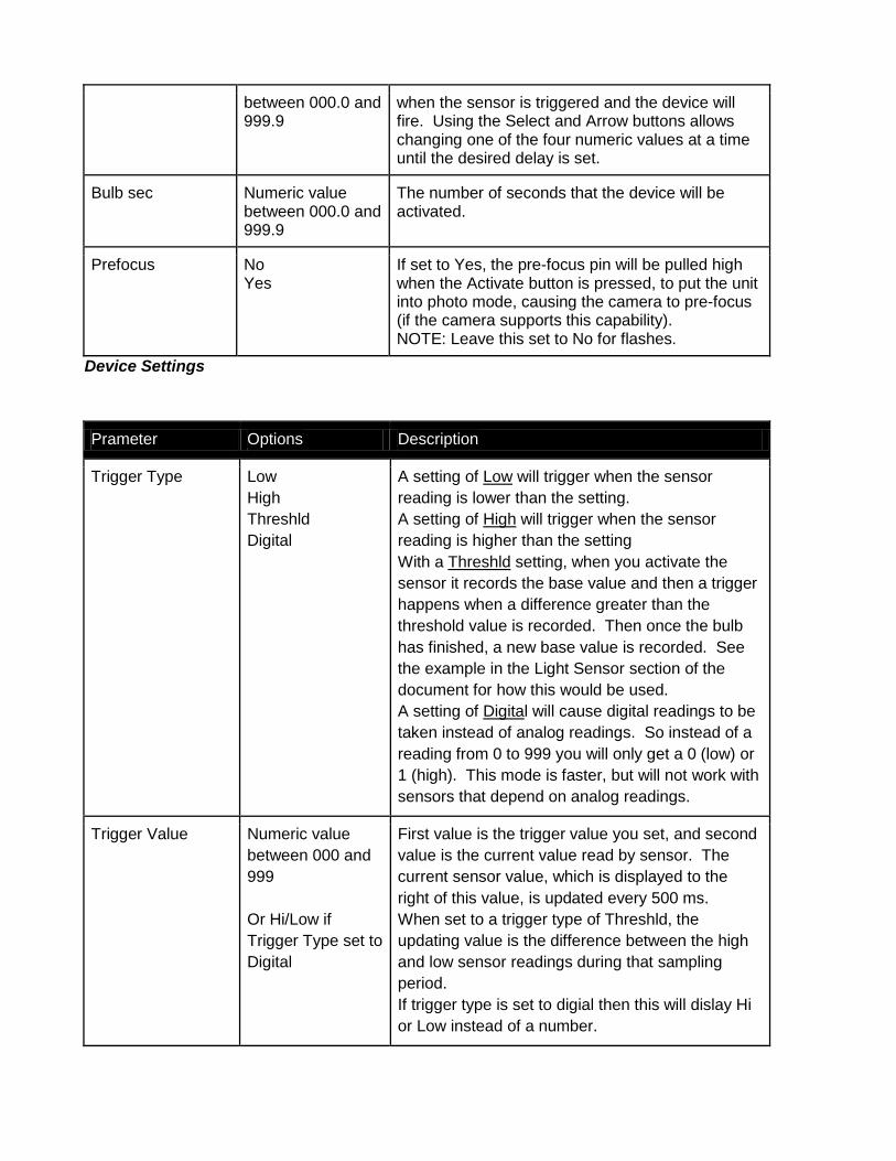
Prameter Options Description
Trigger Type Low
High
Threshld
Digital
A setting of Low will trigger when the sensor
reading is lower than the setting.
A setting of High will trigger when the sensor
reading is higher than the setting
With a Threshld setting, when you activate the
sensor it records the base value and then a trigger
happens when a difference greater than the
threshold value is recorded. Then once the bulb
has finished, a new base value is recorded. See
the example in the Light Sensor section of the
document for how this would be used.
A setting of Digital will cause digital readings to be
taken instead of analog readings. So instead of a
reading from 0 to 999 you will only get a 0 (low) or
1 (high). This mode is faster, but will not work with
sensors that depend on analog readings.
Trigger Value Numeric value
between 000 and
999
Or Hi/Low if
Trigger Type set to
Digital
First value is the trigger value you set, and second
value is the current value read by sensor. The
current sensor value, which is displayed to the
right of this value, is updated every 500 ms.
When set to a trigger type of Threshld, the
updating value is the difference between the high
and low sensor readings during that sampling
period.
If trigger type is set to digial then this will dislay Hi
or Low instead of a number.
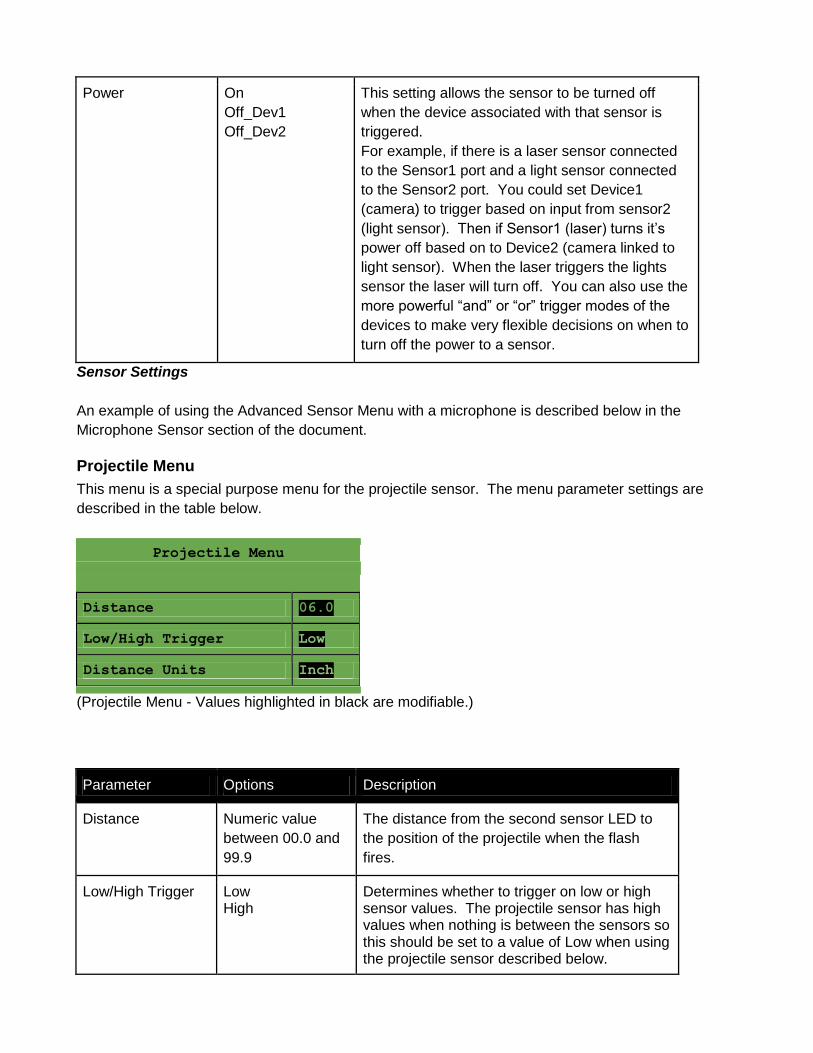
Power On
Off_Dev1
Off_Dev2
This setting allows the sensor to be turned off
when the device associated with that sensor is
triggered.
For example, if there is a laser sensor connected
to the Sensor1 port and a light sensor connected
to the Sensor2 port. You could set Device1
(camera) to trigger based on input from sensor2
(light sensor). Then if Sensor1 (laser) turns it’s
power off based on to Device2 (camera linked to
light sensor). When the laser triggers the lights
sensor the laser will turn off. You can also use the
more powerful “and” or “or” trigger modes of the
devices to make very flexible decisions on when to
turn off the power to a sensor.
Sensor Settings
An example of using the Advanced Sensor Menu with a microphone is described below in the
Microphone Sensor section of the document.
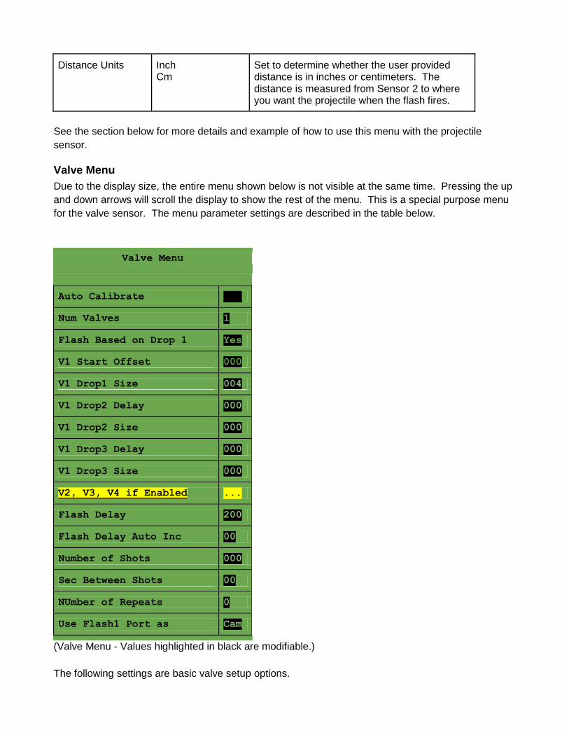
Projectile Menu
This menu is a special purpose menu for the projectile sensor. The menu parameter settings are
described in the table below.
Projectile Menu
Distance 06.0
Low/High Trigger Low
Distance Units Inch
(Projectile Menu - Values highlighted in black are modifiable.)
Parameter Options Description
Distance Numeric value
between 00.0 and
99.9
The distance from the second sensor LED to
the position of the projectile when the flash
fires.
Low/High Trigger Low High
Determines whether to trigger on low or high sensor values. The projectile sensor has high values when nothing is between the sensors so this should be set to a value of Low when using the projectile sensor described below.
Distance Units Inch Cm
Set to determine whether the user provided distance is in inches or centimeters. The distance is measured from Sensor 2 to where you want the projectile when the flash fires.
See the section below for more details and example of how to use this menu with the projectile
sensor.
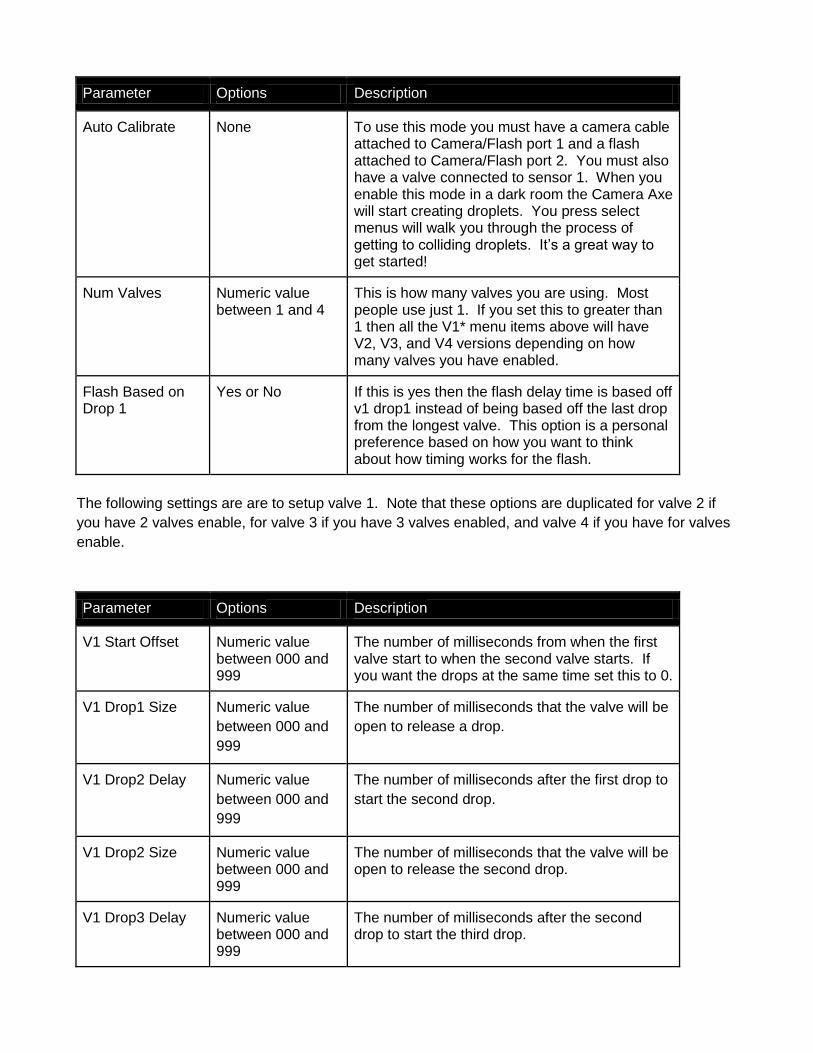
Valve Menu
Due to the display size, the entire menu shown below is not visible at the same time. Pressing the up
and down arrows will scroll the display to show the rest of the menu. This is a special purpose menu
for the valve sensor. The menu parameter settings are described in the table below.
Valve Menu
Auto Calibrate ___
Num Valves 1
Flash Based on Drop 1 Yes
V1 Start Offset 000
V1 Drop1 Size 004
V1 Drop2 Delay 000
V1 Drop2 Size 000
V1 Drop3 Delay 000
V1 Drop3 Size 000
V2, V3, V4 if Enabled ...
Flash Delay 200
Flash Delay Auto Inc 00
Number of Shots 000
Sec Between Shots 00
NUmber of Repeats 0
Use Flash1 Port as Cam
(Valve Menu - Values highlighted in black are modifiable.)
The following settings are basic valve setup options.
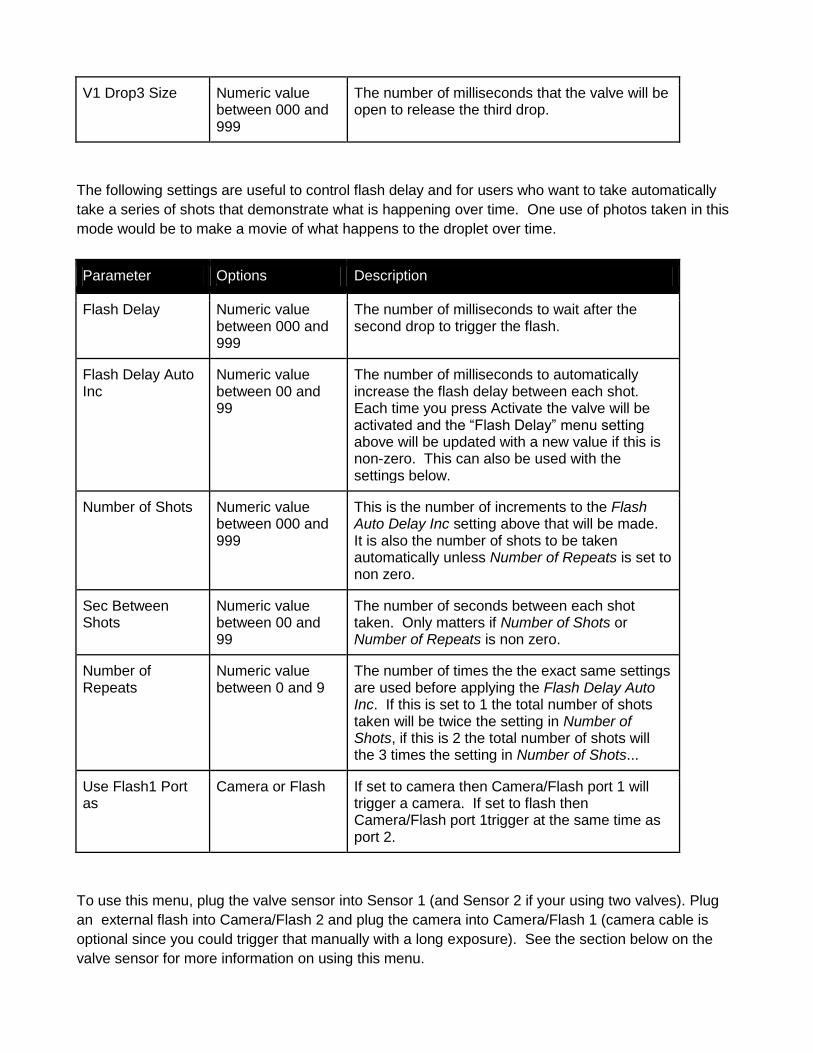
Parameter Options Description
Auto Calibrate None To use this mode you must have a camera cable attached to Camera/Flash port 1 and a flash attached to Camera/Flash port 2. You must also have a valve connected to sensor 1. When you enable this mode in a dark room the Camera Axe will start creating droplets. You press select menus will walk you through the process of getting to colliding droplets. It’s a great way to get started!
Num Valves Numeric value between 1 and 4
This is how many valves you are using. Most people use just 1. If you set this to greater than 1 then all the V1* menu items above will have V2, V3, and V4 versions depending on how many valves you have enabled.
Flash Based on Drop 1
Yes or No If this is yes then the flash delay time is based off v1 drop1 instead of being based off the last drop from the longest valve. This option is a personal preference based on how you want to think about how timing works for the flash.
The following settings are are to setup valve 1. Note that these options are duplicated for valve 2 if
you have 2 valves enable, for valve 3 if you have 3 valves enabled, and valve 4 if you have for valves
enable.
Parameter Options Description
V1 Start Offset Numeric value between 000 and 999
The number of milliseconds from when the first valve start to when the second valve starts. If you want the drops at the same time set this to 0.
V1 Drop1 Size Numeric value
between 000 and
999
The number of milliseconds that the valve will be
open to release a drop.
V1 Drop2 Delay Numeric value
between 000 and
999
The number of milliseconds after the first drop to
start the second drop.
V1 Drop2 Size Numeric value between 000 and 999
The number of milliseconds that the valve will be open to release the second drop.
V1 Drop3 Delay Numeric value between 000 and 999
The number of milliseconds after the second drop to start the third drop.
V1 Drop3 Size Numeric value between 000 and 999
The number of milliseconds that the valve will be open to release the third drop.
The following settings are useful to control flash delay and for users who want to take automatically
take a series of shots that demonstrate what is happening over time. One use of photos taken in this
mode would be to make a movie of what happens to the droplet over time.
Parameter Options Description
Flash Delay Numeric value between 000 and 999
The number of milliseconds to wait after the second drop to trigger the flash.
Flash Delay Auto Inc
Numeric value between 00 and 99
The number of milliseconds to automatically increase the flash delay between each shot. Each time you press Activate the valve will be activated and the “Flash Delay” menu setting above will be updated with a new value if this is non-zero. This can also be used with the settings below.
Number of Shots Numeric value between 000 and 999
This is the number of increments to the Flash Auto Delay Inc setting above that will be made. It is also the number of shots to be taken automatically unless Number of Repeats is set to non zero.
Sec Between Shots
Numeric value between 00 and 99
The number of seconds between each shot taken. Only matters if Number of Shots or Number of Repeats is non zero.
Number of Repeats
Numeric value between 0 and 9
The number of times the the exact same settings are used before applying the Flash Delay Auto Inc. If this is set to 1 the total number of shots taken will be twice the setting in Number of Shots, if this is 2 the total number of shots will the 3 times the setting in Number of Shots...
Use Flash1 Port as
Camera or Flash If set to camera then Camera/Flash port 1 will trigger a camera. If set to flash then Camera/Flash port 1trigger at the same time as port 2.
To use this menu, plug the valve sensor into Sensor 1 (and Sensor 2 if your using two valves). Plug
an external flash into Camera/Flash 2 and plug the camera into Camera/Flash 1 (camera cable is
optional since you could trigger that manually with a long exposure). See the section below on the
valve sensor for more information on using this menu.
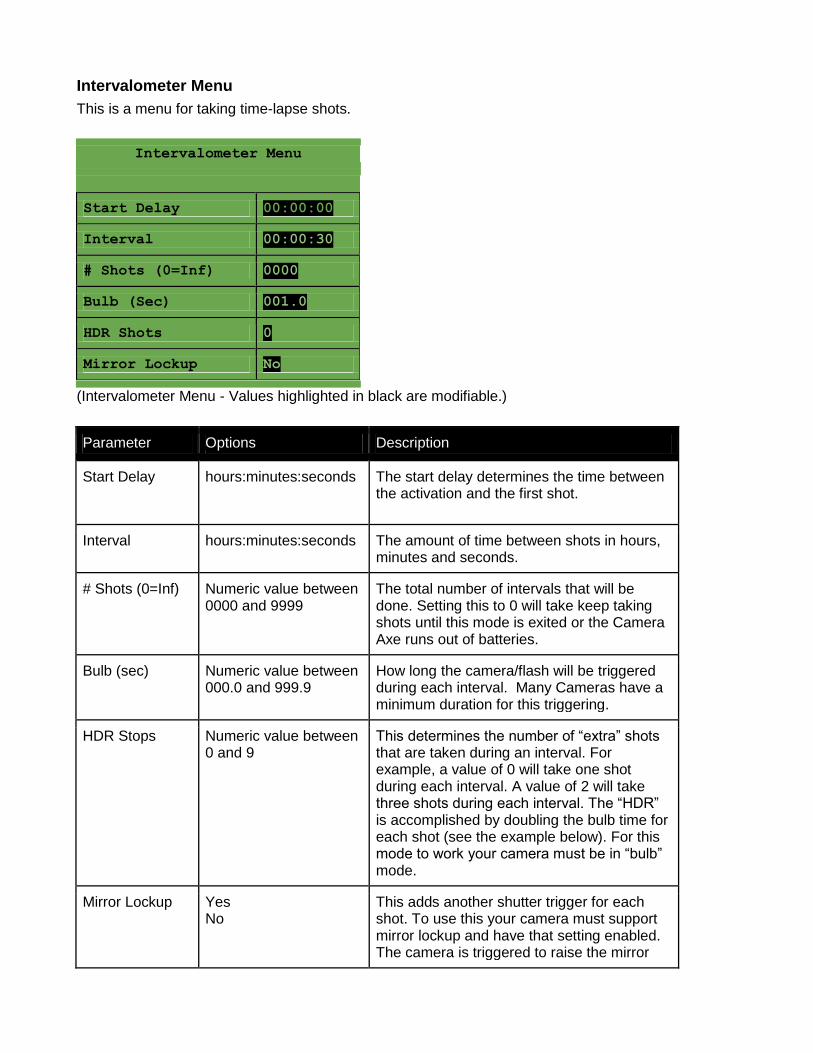
Intervalometer Menu
This is a menu for taking time-lapse shots.
Intervalometer Menu
Start Delay 00:00:00
Interval 00:00:30
# Shots (0=Inf) 0000
Bulb (Sec) 001.0
HDR Shots 0
Mirror Lockup No
(Intervalometer Menu - Values highlighted in black are modifiable.)
Parameter Options Description
Start Delay hours:minutes:seconds The start delay determines the time between the activation and the first shot.
Interval hours:minutes:seconds The amount of time between shots in hours, minutes and seconds.
# Shots (0=Inf) Numeric value between 0000 and 9999
The total number of intervals that will be done. Setting this to 0 will take keep taking shots until this mode is exited or the Camera Axe runs out of batteries.
Bulb (sec) Numeric value between 000.0 and 999.9
How long the camera/flash will be triggered during each interval. Many Cameras have a minimum duration for this triggering.
HDR Stops Numeric value between 0 and 9
This determines the number of “extra” shots that are taken during an interval. For example, a value of 0 will take one shot during each interval. A value of 2 will take three shots during each interval. The “HDR” is accomplished by doubling the bulb time for each shot (see the example below). For this mode to work your camera must be in “bulb” mode.
Mirror Lockup Yes No
This adds another shutter trigger for each shot. To use this your camera must support mirror lockup and have that setting enabled. The camera is triggered to raise the mirror
and then two seconds later (to allow the vibration to settle) there is another shutter trigger to take the shot. This works with the camera in mirror lockup mode for cameras that require two shutter presses to take the shot in mirror lockup mode. In this mode, the mirror lockup shutter trigger is ½ second plus the 1.5 second delay.
An example of how this might be used:
Parameter Options
Start Delay 00:00:05
Interval 00:01:00
# Shots (0=Inf) 2
Bulb (sec) 001.0
HDR Stops 3
Mirror Lockup No
This would trigger a total of 8 shots. The first one would be after 5 seconds with a 1 second shutter
trigger. The 2nd would be about a half second later with a 2 second shutter trigger, the 3rd would
have a 4 second shutter trigger and the 4th would have an 8 second shutter trigger. The 5th through
8th shots would start at 1 minute 5 seconds from activation and would have shutter trigger times of
1,2,4,8 seconds respectively. This menu is really only used for taking shots in the dark or with heavy
neutral density filters on the lens because the shortest shutter times that can be done (for a 4 shot
HDR sequence would be 0.1, 0.2, 0.4 and 0.8 seconds). The reason the minimum granularity 1/10th
of a second is because many cameras don't allow a bulb time of less than this. Even 1/10th of a
second may be too quick for some cameras. If you’re have trouble with your camera not triggering
reliably try increasing this. One second should be a safe value for all cameras.
This menu now also supports manual bramping. As the intervalometer is running you can use the up
and down keys to adjust the bulb setting. The new setting will be displayed on the screen.
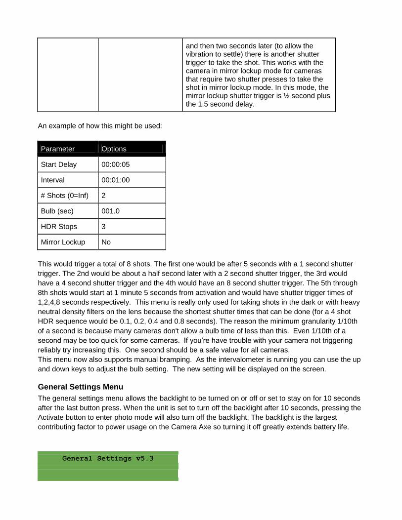
General Settings Menu
The general settings menu allows the backlight to be turned on or off or set to stay on for 10 seconds
after the last button press. When the unit is set to turn off the backlight after 10 seconds, pressing the
Activate button to enter photo mode will also turn off the backlight. The backlight is the largest
contributing factor to power usage on the Camera Axe so turning it off greatly extends battery life.
General Settings v5.3
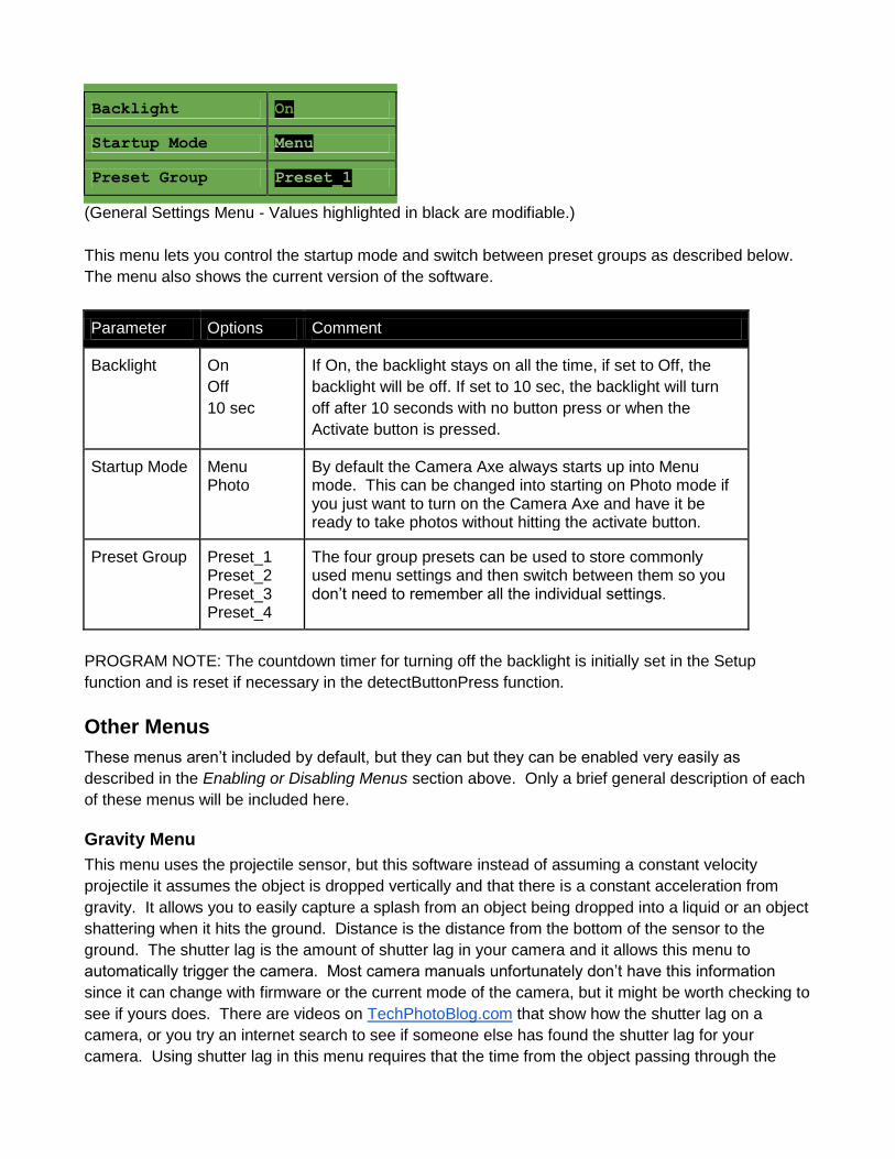
Backlight On
Startup Mode Menu
Preset Group Preset_1
(General Settings Menu - Values highlighted in black are modifiable.)
This menu lets you control the startup mode and switch between preset groups as described below.
The menu also shows the current version of the software.
Parameter Options Comment
Backlight On
Off
10 sec
If On, the backlight stays on all the time, if set to Off, the
backlight will be off. If set to 10 sec, the backlight will turn
off after 10 seconds with no button press or when the
Activate button is pressed.
Startup Mode Menu Photo
By default the Camera Axe always starts up into Menu mode. This can be changed into starting on Photo mode if you just want to turn on the Camera Axe and have it be ready to take photos without hitting the activate button.
Preset Group Preset_1 Preset_2 Preset_3 Preset_4
The four group presets can be used to store commonly used menu settings and then switch between them so you don’t need to remember all the individual settings.
PROGRAM NOTE: The countdown timer for turning off the backlight is initially set in the Setup
function and is reset if necessary in the detectButtonPress function.
Other Menus
These menus aren’t included by default, but they can but they can be enabled very easily as
described in the Enabling or Disabling Menus section above. Only a brief general description of each
of these menus will be included here.
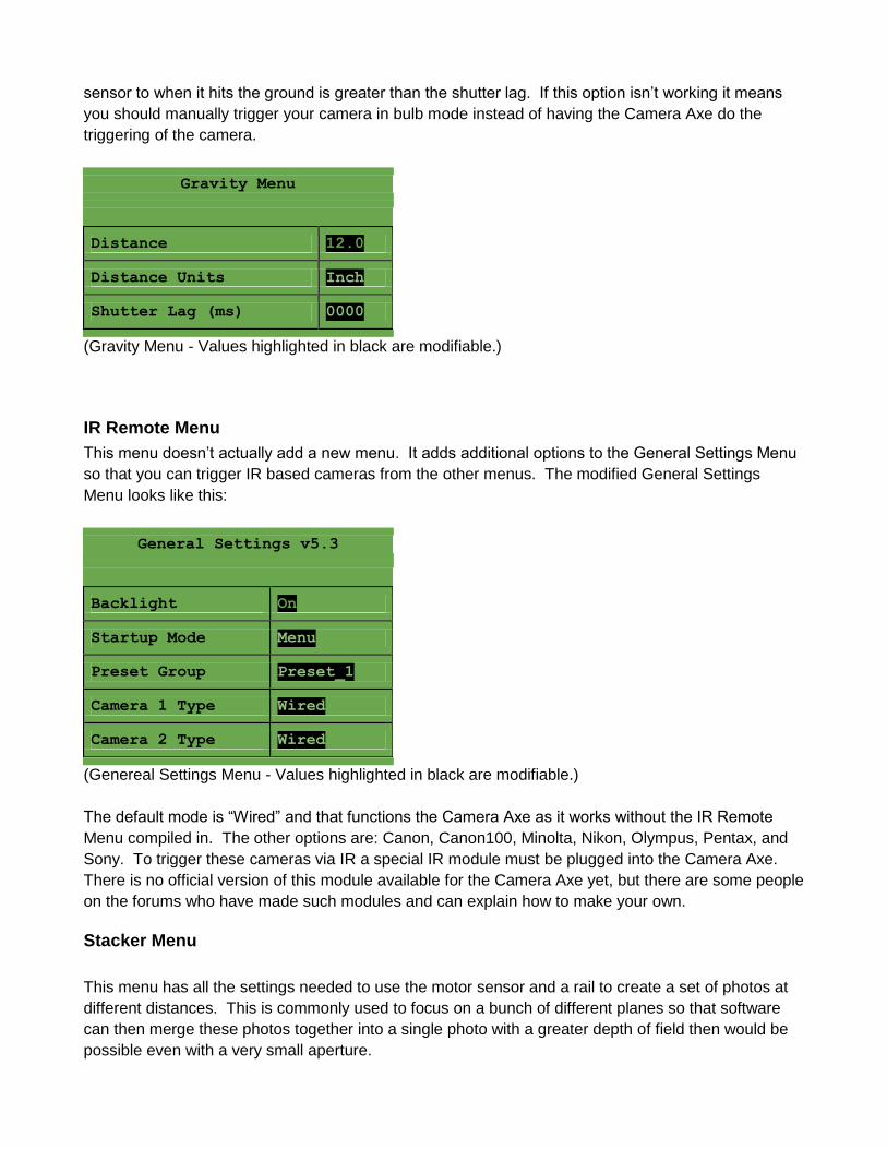
Gravity Menu
This menu uses the projectile sensor, but this software instead of assuming a constant velocity
projectile it assumes the object is dropped vertically and that there is a constant acceleration from
gravity. It allows you to easily capture a splash from an object being dropped into a liquid or an object
shattering when it hits the ground. Distance is the distance from the bottom of the sensor to the
ground. The shutter lag is the amount of shutter lag in your camera and it allows this menu to
automatically trigger the camera. Most camera manuals unfortunately don’t have this information
since it can change with firmware or the current mode of the camera, but it might be worth checking to
see if yours does. There are videos on TechPhotoBlog.com that show how the shutter lag on a
camera, or you try an internet search to see if someone else has found the shutter lag for your
camera. Using shutter lag in this menu requires that the time from the object passing through the
sensor to when it hits the ground is greater than the shutter lag. If this option isn’t working it means
you should manually trigger your camera in bulb mode instead of having the Camera Axe do the
triggering of the camera.
Gravity Menu
Distance 12.0
Distance Units Inch
Shutter Lag (ms) 0000
(Gravity Menu - Values highlighted in black are modifiable.)
IR Remote Menu
This menu doesn’t actually add a new menu. It adds additional options to the General Settings Menu
so that you can trigger IR based cameras from the other menus. The modified General Settings
Menu looks like this:
General Settings v5.3
Backlight On
Startup Mode Menu
Preset Group Preset_1
Camera 1 Type Wired
Camera 2 Type Wired
(Genereal Settings Menu - Values highlighted in black are modifiable.)
The default mode is “Wired” and that functions the Camera Axe as it works without the IR Remote
Menu compiled in. The other options are: Canon, Canon100, Minolta, Nikon, Olympus, Pentax, and
Sony. To trigger these cameras via IR a special IR module must be plugged into the Camera Axe.
There is no official version of this module available for the Camera Axe yet, but there are some people
on the forums who have made such modules and can explain how to make your own.
Stacker Menu
This menu has all the settings needed to use the motor sensor and a rail to create a set of photos at
different distances. This is commonly used to focus on a bunch of different planes so that software
can then merge these photos together into a single photo with a greater depth of field then would be
possible even with a very small aperture.
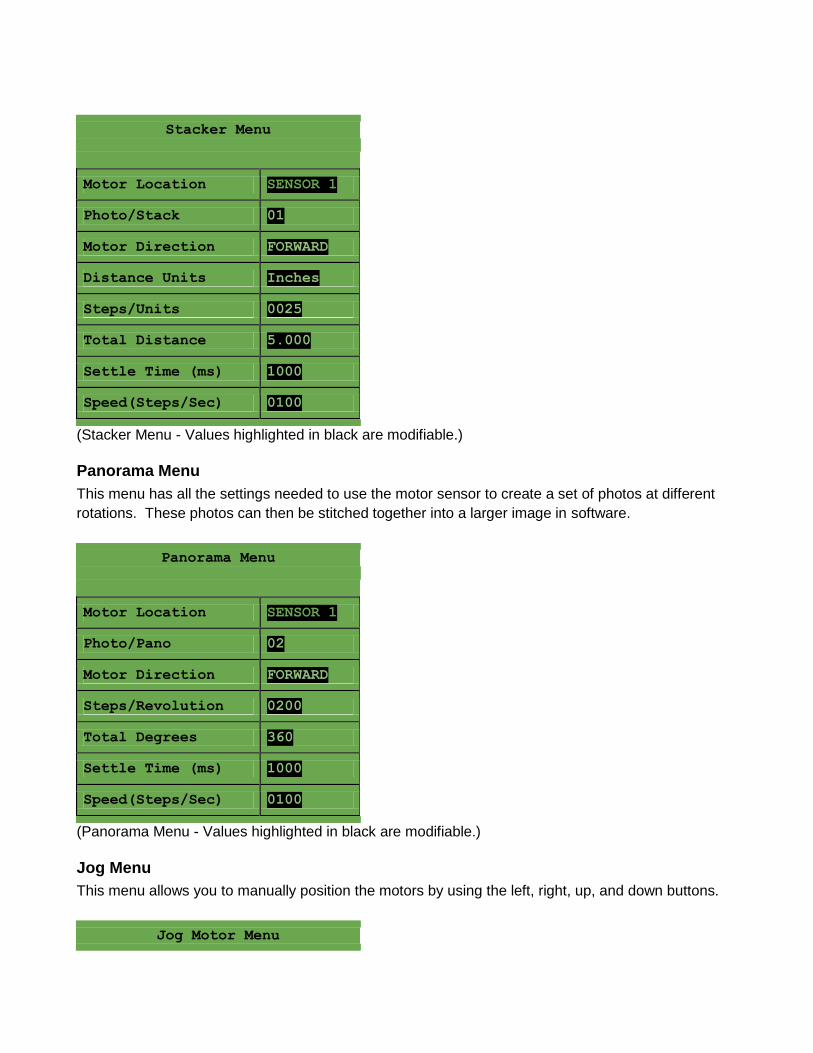
Stacker Menu
Motor Location SENSOR 1
Photo/Stack 01
Motor Direction FORWARD
Distance Units Inches
Steps/Units 0025
Total Distance 5.000
Settle Time (ms) 1000
Speed(Steps/Sec) 0100
(Stacker Menu - Values highlighted in black are modifiable.)
Panorama Menu
This menu has all the settings needed to use the motor sensor to create a set of photos at different
rotations. These photos can then be stitched together into a larger image in software.
Panorama Menu
Motor Location SENSOR 1
Photo/Pano 02
Motor Direction FORWARD
Steps/Revolution 0200
Total Degrees 360
Settle Time (ms) 1000
Speed(Steps/Sec) 0100
(Panorama Menu - Values highlighted in black are modifiable.)
Jog Menu
This menu allows you to manually position the motors by using the left, right, up, and down buttons.
Jog Motor Menu
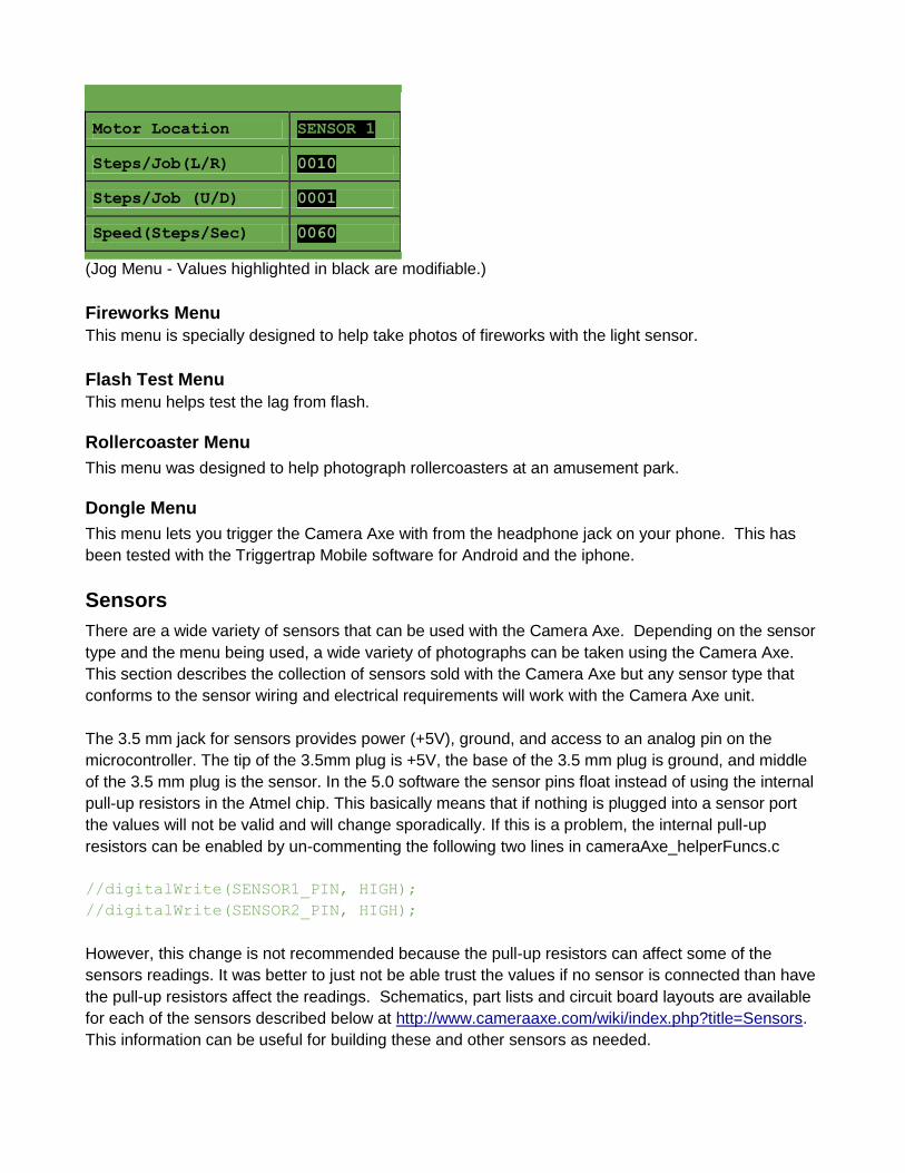
Motor Location SENSOR 1
Steps/Job(L/R) 0010
Steps/Job (U/D) 0001
Speed(Steps/Sec) 0060
(Jog Menu - Values highlighted in black are modifiable.)
Fireworks Menu
This menu is specially designed to help take photos of fireworks with the light sensor.
Flash Test Menu
This menu helps test the lag from flash.
Rollercoaster Menu
This menu was designed to help photograph rollercoasters at an amusement park.
Dongle Menu
This menu lets you trigger the Camera Axe with from the headphone jack on your phone. This has
been tested with the Triggertrap Mobile software for Android and the iphone.
Sensors
There are a wide variety of sensors that can be used with the Camera Axe. Depending on the sensor
type and the menu being used, a wide variety of photographs can be taken using the Camera Axe.
This section describes the collection of sensors sold with the Camera Axe but any sensor type that
conforms to the sensor wiring and electrical requirements will work with the Camera Axe unit.
The 3.5 mm jack for sensors provides power (+5V), ground, and access to an analog pin on the
microcontroller. The tip of the 3.5mm plug is +5V, the base of the 3.5 mm plug is ground, and middle
of the 3.5 mm plug is the sensor. In the 5.0 software the sensor pins float instead of using the internal
pull-up resistors in the Atmel chip. This basically means that if nothing is plugged into a sensor port
the values will not be valid and will change sporadically. If this is a problem, the internal pull-up
resistors can be enabled by un-commenting the following two lines in cameraAxe_helperFuncs.c
//digitalWrite(SENSOR1_PIN, HIGH);
//digitalWrite(SENSOR2_PIN, HIGH);
However, this change is not recommended because the pull-up resistors can affect some of the
sensors readings. It was better to just not be able trust the values if no sensor is connected than have
the pull-up resistors affect the readings. Schematics, part lists and circuit board layouts are available
for each of the sensors described below at http://www.cameraaxe.com/wiki/index.php?title=Sensors.
This information can be useful for building these and other sensors as needed.
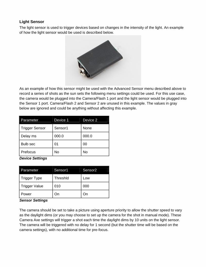
Light Sensor
The light sensor is used to trigger devices based on changes in the intensity of the light. An example
of how the light sensor would be used is described below.
As an example of how this sensor might be used with the Advanced Sensor menu described above to
record a series of shots as the sun sets the following menu settings could be used. For this use case,
the camera would be plugged into the Camera/Flash 1 port and the light sensor would be plugged into
the Sensor 1 port. Camera/Flash 2 and Sensor 2 are unused in this example. The values in gray
below are ignored and could be anything without affecting this example.
Parameter Device 1 Device 2
Trigger Sensor Sensor1 None
Delay ms 000.0 000.0
Bulb sec 01 00
Prefocus No No
Device Settings
Parameter Sensor1 Sensor2
Trigger Type Threshld Low
Trigger Value 010 000
Power On On
Sensor Settings
The camera should be set to take a picture using aperture priority to allow the shutter speed to vary
as the daylight dims (or you may choose to set up the camera for the shot in manual mode). These
Camera Axe settings will trigger a shot each time the daylight dims by 10 units on the light sensor.
The camera will be triggered with no delay for 1 second (but the shutter time will be based on the
camera settings), with no additional time for pre-focus.
When you start the sensor it records the base value and then a trigger happens when a difference
greater than the threshold value is recorded. Then once the bulb has finished a new base value is
recorded. This works well for sunsets where you want to take a picture as the light changed gradually.
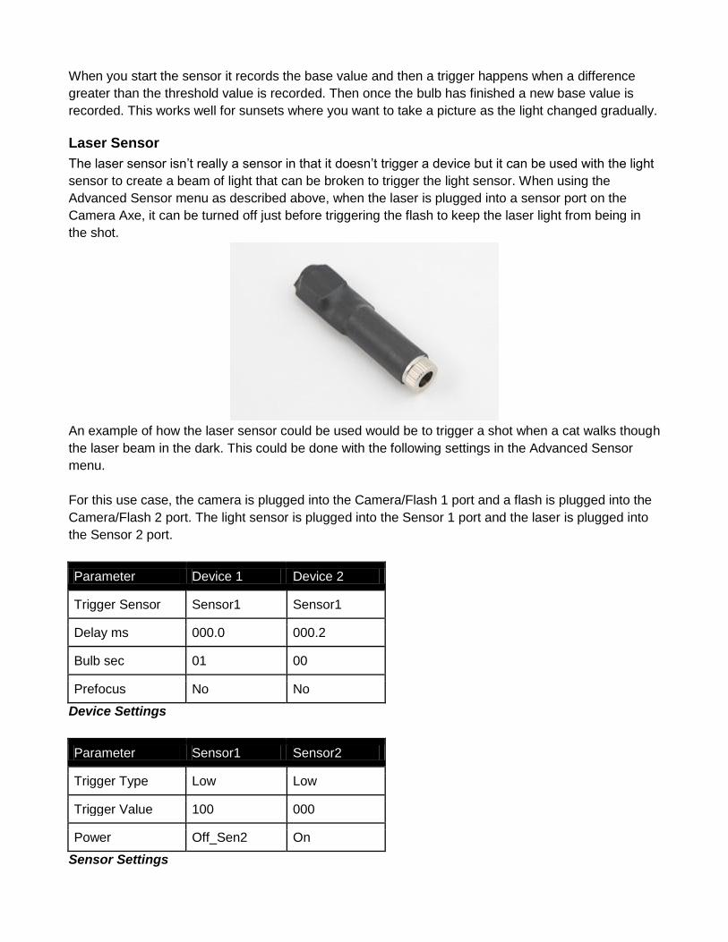
Laser Sensor
The laser sensor isn’t really a sensor in that it doesn’t trigger a device but it can be used with the light
sensor to create a beam of light that can be broken to trigger the light sensor. When using the
Advanced Sensor menu as described above, when the laser is plugged into a sensor port on the
Camera Axe, it can be turned off just before triggering the flash to keep the laser light from being in
the shot.
An example of how the laser sensor could be used would be to trigger a shot when a cat walks though
the laser beam in the dark. This could be done with the following settings in the Advanced Sensor
menu.
For this use case, the camera is plugged into the Camera/Flash 1 port and a flash is plugged into the
Camera/Flash 2 port. The light sensor is plugged into the Sensor 1 port and the laser is plugged into
the Sensor 2 port.
Parameter Device 1 Device 2
Trigger Sensor Sensor1 Sensor1
Delay ms 000.0 000.2
Bulb sec 01 00
Prefocus No No
Device Settings
Parameter Sensor1 Sensor2
Trigger Type Low Low
Trigger Value 100 000
Power Off_Sen2 On
Sensor Settings
The camera should be set to manual mode and the aperture and shutter speed should be set as
appropriate for the flash value. The delay for Device 2 (the flash) is to allow the shutter on the camera
to open before the flash triggers. The Power setting of Off_Sen2 turns the laser off before the camera
is triggered to keep the laser beam from being in the shot. The shot will be triggered when the light
sensor value goes below 100 (this value may need to be adjusted up or down depending on the
sensor reading when the laser is on verses off the light sensor).
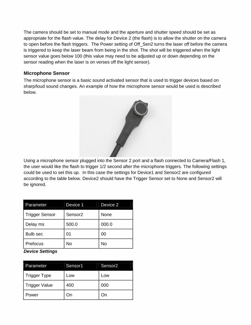
Microphone Sensor
The microphone sensor is a basic sound activated sensor that is used to trigger devices based on
sharp/loud sound changes. An example of how the microphone sensor would be used is described
below.
Using a microphone sensor plugged into the Sensor 2 port and a flash connected to Camera/Flash 1,
the user would like the flash to trigger 1/2 second after the microphone triggers. The following settings
could be used to set this up. In this case the settings for Device1 and Sensor2 are configured
according to the table below. Device2 should have the Trigger Sensor set to None and Sensor2 will
be ignored.
Parameter Device 1 Device 2
Trigger Sensor Sensor2 None
Delay ms 500.0 000.0
Bulb sec 01 00
Prefocus No No
Device Settings
Parameter Sensor1 Sensor2
Trigger Type Low Low
Trigger Value 400 000
Power On On
Sensor Settings
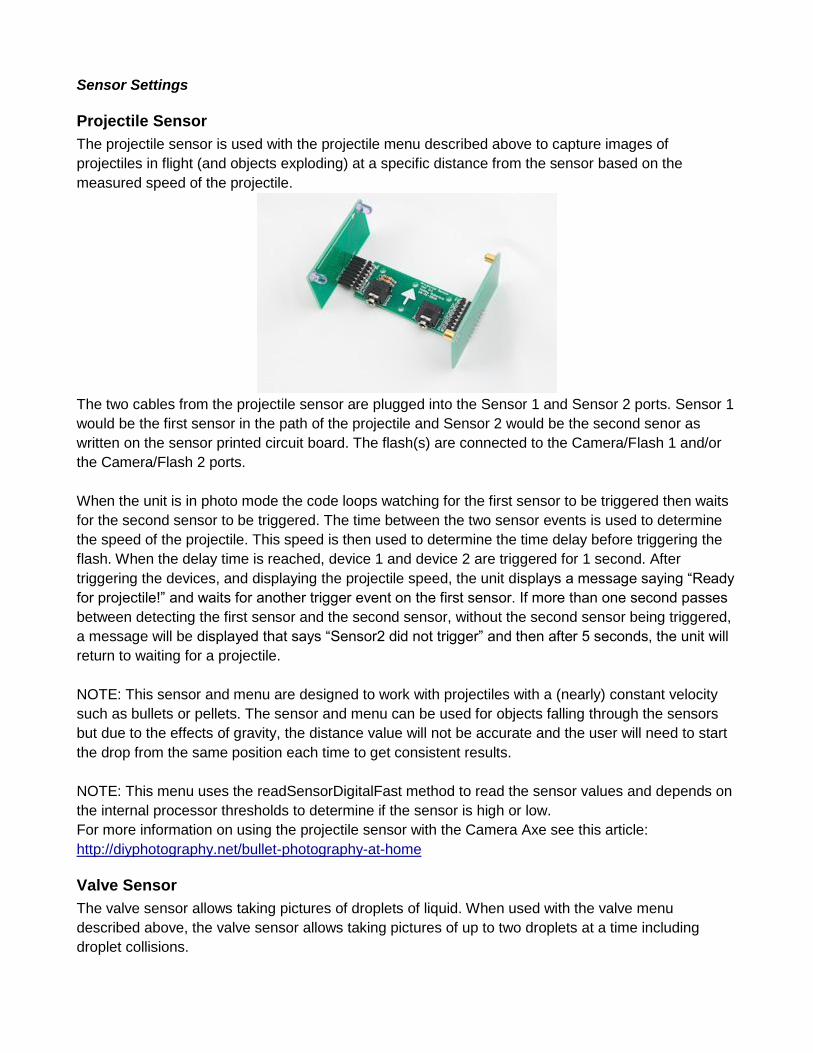
Projectile Sensor
The projectile sensor is used with the projectile menu described above to capture images of
projectiles in flight (and objects exploding) at a specific distance from the sensor based on the
measured speed of the projectile.
The two cables from the projectile sensor are plugged into the Sensor 1 and Sensor 2 ports. Sensor 1
would be the first sensor in the path of the projectile and Sensor 2 would be the second senor as
written on the sensor printed circuit board. The flash(s) are connected to the Camera/Flash 1 and/or
the Camera/Flash 2 ports.
When the unit is in photo mode the code loops watching for the first sensor to be triggered then waits
for the second sensor to be triggered. The time between the two sensor events is used to determine
the speed of the projectile. This speed is then used to determine the time delay before triggering the
flash. When the delay time is reached, device 1 and device 2 are triggered for 1 second. After
triggering the devices, and displaying the projectile speed, the unit displays a message saying “Ready
for projectile!” and waits for another trigger event on the first sensor. If more than one second passes
between detecting the first sensor and the second sensor, without the second sensor being triggered,
a message will be displayed that says “Sensor2 did not trigger” and then after 5 seconds, the unit will
return to waiting for a projectile.
NOTE: This sensor and menu are designed to work with projectiles with a (nearly) constant velocity
such as bullets or pellets. The sensor and menu can be used for objects falling through the sensors
but due to the effects of gravity, the distance value will not be accurate and the user will need to start
the drop from the same position each time to get consistent results.
NOTE: This menu uses the readSensorDigitalFast method to read the sensor values and depends on
the internal processor thresholds to determine if the sensor is high or low.
For more information on using the projectile sensor with the Camera Axe see this article:
http://diyphotography.net/bullet-photography-at-home
Valve Sensor
The valve sensor allows taking pictures of droplets of liquid. When used with the valve menu
described above, the valve sensor allows taking pictures of up to two droplets at a time including
droplet collisions.
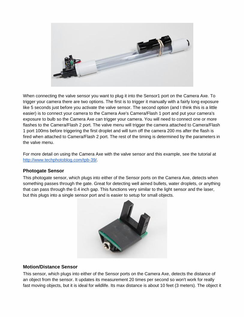
When connecting the valve sensor you want to plug it into the Sensor1 port on the Camera Axe. To
trigger your camera there are two options. The first is to trigger it manually with a fairly long exposure
like 5 seconds just before you activate the valve sensor. The second option (and I think this is a little
easier) is to connect your camera to the Camera Axe's Camera/Flash 1 port and put your camera's
exposure to bulb so the Camera Axe can trigger your camera. You will need to connect one or more
flashes to the Camera/Flash 2 port. The valve menu will trigger the camera attached to Camera/Flash
1 port 100ms before triggering the first droplet and will turn off the camera 200 ms after the flash is
fired when attached to Camera/Flash 2 port. The rest of the timing is determined by the parameters in
the valve menu.
For more detail on using the Camera Axe with the valve sensor and this example, see the tutorial at
http://www.techphotoblog.com/tpb-39/.
Photogate Sensor
This photogate sensor, which plugs into either of the Sensor ports on the Camera Axe, detects when
something passes through the gate. Great for detecting well aimed bullets, water droplets, or anything
that can pass through the 0.4 inch gap. This functions very similar to the light sensor and the laser,
but this plugs into a single sensor port and is easier to setup for small objects.
Motion/Distance Sensor
This sensor, which plugs into either of the Sensor ports on the Camera Axe, detects the distance of
an object from the sensor. It updates its measurement 20 times per second so won't work for really
fast moving objects, but it is ideal for wildlife. Its max distance is about 10 feet (3 meters). The object it
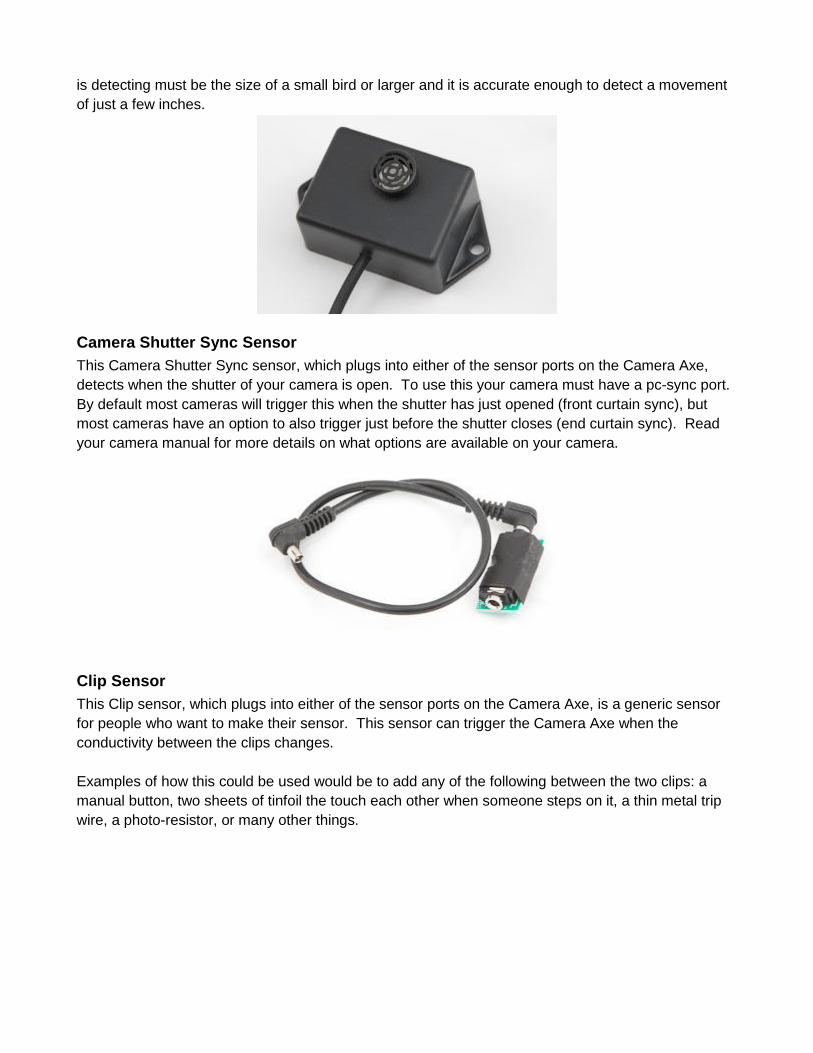
is detecting must be the size of a small bird or larger and it is accurate enough to detect a movement
of just a few inches.
Camera Shutter Sync Sensor
This Camera Shutter Sync sensor, which plugs into either of the sensor ports on the Camera Axe,
detects when the shutter of your camera is open. To use this your camera must have a pc-sync port.
By default most cameras will trigger this when the shutter has just opened (front curtain sync), but
most cameras have an option to also trigger just before the shutter closes (end curtain sync). Read
your camera manual for more details on what options are available on your camera.
Clip Sensor
This Clip sensor, which plugs into either of the sensor ports on the Camera Axe, is a generic sensor
for people who want to make their sensor. This sensor can trigger the Camera Axe when the
conductivity between the clips changes.
Examples of how this could be used would be to add any of the following between the two clips: a
manual button, two sheets of tinfoil the touch each other when someone steps on it, a thin metal trip
wire, a photo-resistor, or many other things.
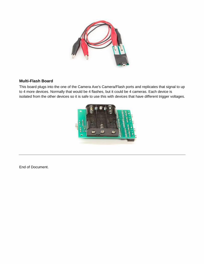
Multi-Flash Board
This board plugs into the one of the Camera Axe's Camera/Flash ports and replicates that signal to up
to 4 more devices. Normally that would be 4 flashes, but it could be 4 cameras. Each device is
isolated from the other devices so it is safe to use this with devices that have different trigger voltages.
End of Document.