Embed Size (px)
Citation preview
Cam-Line® Plastic Lined Trunnion Ball Valve
Contents
2 Cam-Line®
Introduction ....................................................3
Features ..........................................................4
Lining Material, Seats, Testing .........................5
Cutaway Illustration ........................................6
Technical DataPressure / Temperature Curves ...................7 Operating Torques ....................................7 Flow Coefficients (Cv Values) .....................7
PVDF Coatings ................................................7
Cam-Line® Options ..........................................8
Actuated Valves ..............................................9
Materials of Construction ..............................10
DimensionsManual Valves ........................................10 Actuator Mounting .................................11
Service Guide .......................................... 12–17
Ordering Information ....................................18
Terms and Conditions of Sale ........................19
Page
Cam-Line® 3
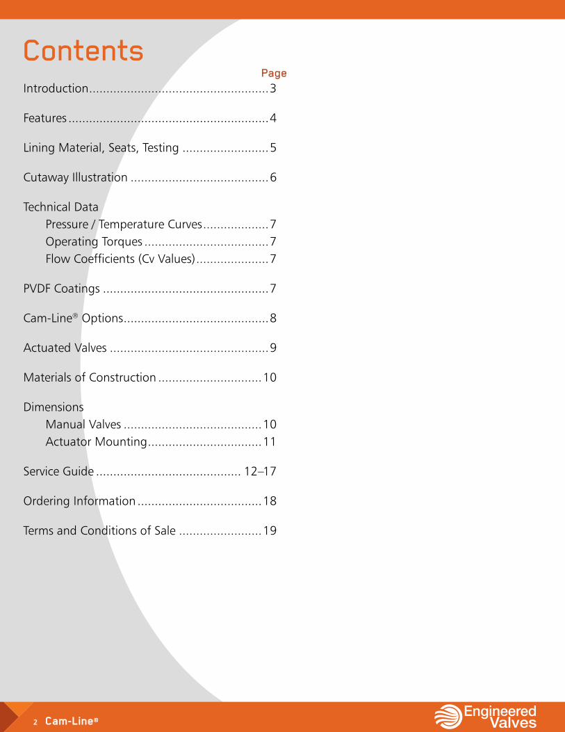
ITT Industries, Engineered Valves Group (EVG) has been an innovator and producer of valves for over fifty years. These valves have gained extensive usage in many industries including power generation, pulp and paper, refineries, chemical process, pharmaceutical/bioprocessing and pollution control. As a recognized leader in the valve business, our heritage stems from diaphragm valves.
Through the years, our product offering has grown extensively. Our corrosion handling expertise has provided the impetus for the design of quarter-turn valve products like our Cam-Line® Ball Valve.
IntroductionBy developing products such as the Cam-Line that address specific problems encountered in industry, we continue to expand our commitment to remain a leader in flow control.
The performance of our products is surpassed only by the care taken in the many facets of manufacturing. Excellence in quality assurance, product reliability, and product safety will always remain paramount.
4 Cam-Line®
New Generation of Plastic Lined ValveThe Cam-Line trunnion ball valve was designed to overcome problems inherent in conventional lined plug and ball valves. The design objective was to produce a lined quarter-turn valve with positive shut off at high and low pressures, a valve with a stem seal that seals, and a valve that is convenient and safe to operate.
Design innovation has resulted in the valve we proudly call the Cam-Line. The Cam-Line ball valve combines the proven, patented sealing technology of the Cam-Tite ball valve with a trunnion mounting. The result is tight shut off, reliable stem seal performance, and a dramatic torque reduction never before possible in a plastic lined quarter-turn valve.
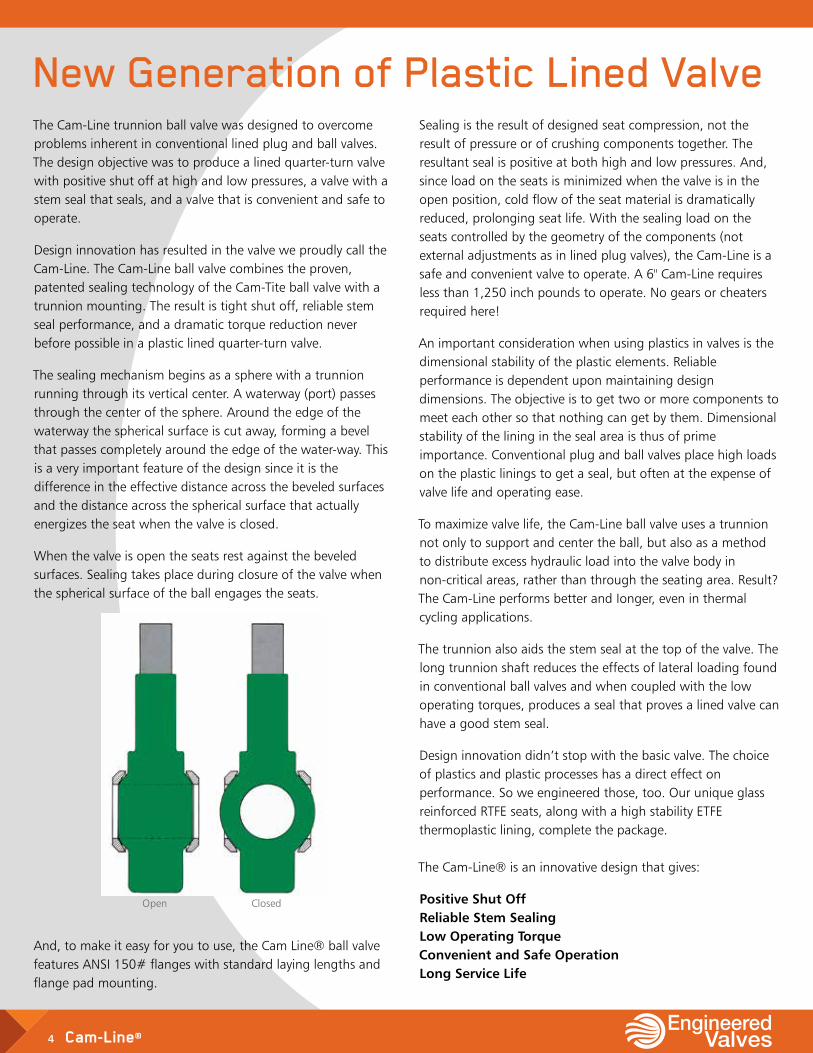
The sealing mechanism begins as a sphere with a trunnion running through its vertical center. A waterway (port) passes through the center of the sphere. Around the edge of the waterway the spherical surface is cut away, forming a bevel that passes completely around the edge of the water-way. This is a very important feature of the design since it is the difference in the effective distance across the beveled surfaces and the distance across the spherical surface that actually energizes the seat when the valve is closed.
When the valve is open the seats rest against the beveled surfaces. Sealing takes place during closure of the valve when the spherical surface of the ball engages the seats.
Sealing is the result of designed seat compression, not the result of pressure or of crushing components together. The resultant seal is positive at both high and low pressures. And, since load on the seats is minimized when the valve is in the open position, cold flow of the seat material is dramatically reduced, prolonging seat life. With the sealing load on the seats controlled by the geometry of the components (not external adjustments as in lined plug valves), the Cam-Line is a safe and convenient valve to operate. A 6" Cam-Line requires less than 1,250 inch pounds to operate. No gears or cheaters required here!
An important consideration when using plastics in valves is the dimensional stability of the plastic elements. Reliable performance is dependent upon maintaining design dimensions. The objective is to get two or more components to meet each other so that nothing can get by them. Dimensional stability of the lining in the seal area is thus of prime importance. Conventional plug and ball valves place high loads on the plastic linings to get a seal, but often at the expense of valve life and operating ease.
To maximize valve life, the Cam-Line ball valve uses a trunnion not only to support and center the ball, but also as a method to distribute excess hydraulic load into the valve body in non-critical areas, rather than through the seating area. Result? The Cam-Line performs better and Ionger, even in thermal cycling applications.
The trunnion also aids the stem seal at the top of the valve. The long trunnion shaft reduces the effects of lateral loading found in conventional ball valves and when coupled with the low operating torques, produces a seal that proves a lined valve can have a good stem seal.
Design innovation didn’t stop with the basic valve. The choice of plastics and plastic processes has a direct effect on performance. So we engineered those, too. Our unique glass reinforced RTFE seats, along with a high stability ETFE thermoplastic lining, complete the package. The Cam-Line® is an innovative design that gives:
Positive Shut Off Reliable Stem Sealing Low Operating Torque Convenient and Safe Operation Long Service Life
Open Closed
And, to make it easy for you to use, the Cam Line® ball valve features ANSI 150# flanges with standard laying lengths and flange pad mounting.
Cam-Line® 5
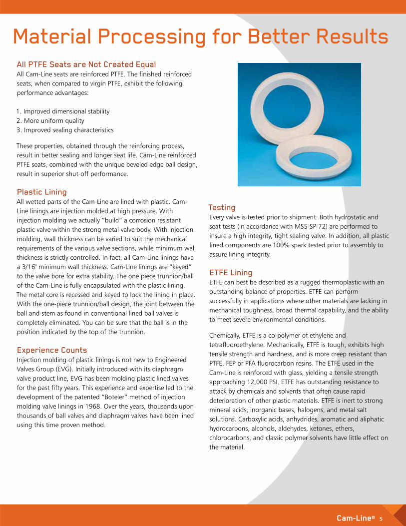
All PTFE Seats are Not Created Equal All Cam-Line seats are reinforced PTFE. The finished reinforced seats, when compared to virgin PTFE, exhibit the following performance advantages: 1. Improved dimensional stability 2. More uniform quality 3. Improved sealing characteristics
These properties, obtained through the reinforcing process, result in better sealing and longer seat life. Cam-Line reinforced PTFE seats, combined with the unique beveled edge ball design, result in superior shut-off performance. Plastic Lining All wetted parts of the Cam-Line are lined with plastic. Cam-Line linings are injection molded at high pressure. With injection molding we actually “build” a corrosion resistant plastic valve within the strong metal valve body. With injection molding, wall thickness can be varied to suit the mechanical requirements of the various valve sections, while minimum wall thickness is strictly controlled. In fact, all Cam-Line linings have a 3/16" minimum wall thickness. Cam-Line linings are “keyed” to the valve bore for extra stability. The one piece trunnion/ball of the Cam-Line is fully encapsulated with the plastic lining. The metal core is recessed and keyed to lock the lining in place. With the one-piece trunnion/ball design, the joint between the ball and stem as found in conventional lined ball valves is completely eliminated. You can be sure that the ball is in the position indicated by the top of the trunnion. Experience Counts Injection molding of plastic linings is not new to Engineered Valves Group (EVG). Initially introduced with its diaphragm valve product line, EVG has been molding plastic lined valves for the past fifty years. This experience and expertise led to the development of the patented “Boteler” method of injection molding valve linings in 1968. Over the years, thousands upon thousands of ball valves and diaphragm valves have been lined using this time proven method.
Material Processing for Better Results
Testing Every valve is tested prior to shipment. Both hydrostatic and seat tests (in accordance with MSS-SP-72) are performed to insure a high integrity, tight sealing valve. In addition, all plastic lined components are 100% spark tested prior to assembly to assure lining integrity. ETFE Lining ETFE can best be described as a rugged thermoplastic with an outstanding balance of properties. ETFE can perform successfully in applications where other materials are lacking in mechanical toughness, broad thermal capability, and the ability to meet severe environmental conditions.
Chemically, ETFE is a co-polymer of ethylene and tetrafluoroethylene. Mechanically, ETFE is tough, exhibits high tensile strength and hardness, and is more creep resistant than PTFE, FEP or PFA fluorocarbon resins. The ETFE used in the Cam-Line is reinforced with glass, yielding a tensile strength approaching 12,000 PSI. ETFE has outstanding resistance to attack by chemicals and solvents that often cause rapid deterioration of other plastic materials. ETFE is inert to strong mineral acids, inorganic bases, halogens, and metal salt solutions. Carboxylic acids, anhydrides, aromatic and aliphatic hydrocarbons, alcohols, aldehydes, ketones, ethers, chlorocarbons, and classic polymer solvents have little effect on the material.
6 Cam-Line®
Plastic Lined Trunnion Ball Valve
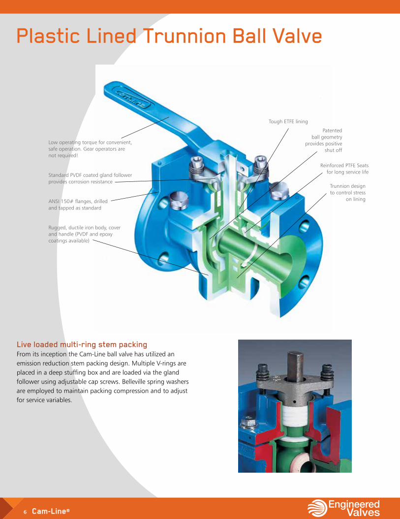
Trunnion design to control stress
on lining
Low operating torque for convenient, safe operation. Gear operators are not required!
Standard PVDF coated gland follower provides corrosion resistance
ANSI 150# flanges, drilled and tapped as standard
Rugged, ductile iron body, cover and handle (PVDF and epoxy coatings available)
Live loaded multi-ring stem packing From its inception the Cam-Line ball valve has utilized an emission reduction stem packing design. Multiple V-rings are placed in a deep stuffing box and are loaded via the gland follower using adjustable cap screws. Belleville spring washers are employed to maintain packing compression and to adjust for service variables.
Tough ETFE lining
Reinforced PTFE Seats for long service life
Patented ball geometry
provides positive shut off
Cam-Line® 7
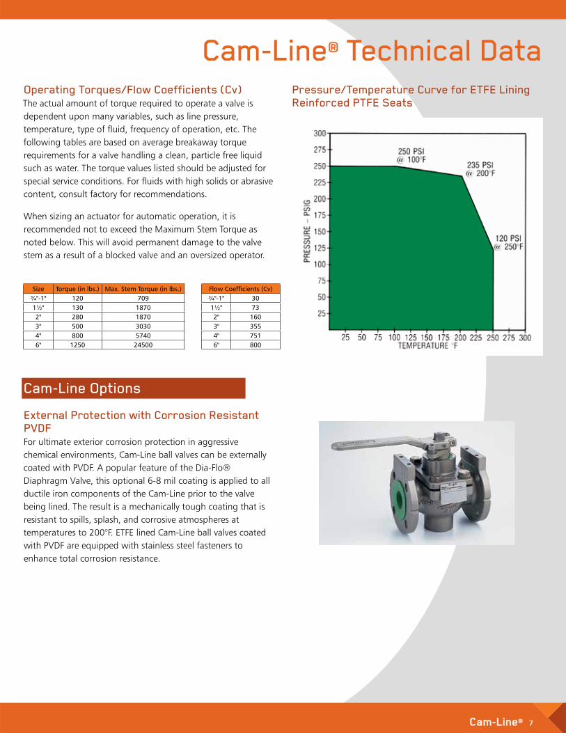
Plastic Lined Trunnion Ball Valve Cam-Line® Technical DataOperating Torques/Flow Coefficients (Cv) The actual amount of torque required to operate a valve is dependent upon many variables, such as line pressure, temperature, type of fluid, frequency of operation, etc. The following tables are based on average breakaway torque requirements for a valve handling a clean, particle free liquid such as water. The torque values listed should be adjusted for special service conditions. For fluids with high solids or abrasive content, consult factory for recommendations.
When sizing an actuator for automatic operation, it is recommended not to exceed the Maximum Stem Torque as noted below. This will avoid permanent damage to the valve stem as a result of a blocked valve and an oversized operator.
Pressure/Temperature Curve for ETFE Lining Reinforced PTFE Seats
Cam-Line Options External Protection with Corrosion Resistant PVDF For ultimate exterior corrosion protection in aggressive chemical environments, Cam-Line ball valves can be externally coated with PVDF. A popular feature of the Dia-Flo® Diaphragm Valve, this optional 6-8 mil coating is applied to all ductile iron components of the Cam-Line prior to the valve being lined. The result is a mechanically tough coating that is resistant to spills, splash, and corrosive atmospheres at temperatures to 200°F. ETFE lined Cam-Line ball valves coated with PVDF are equipped with stainless steel fasteners to enhance total corrosion resistance.
Size Torque (in lbs.) Max. Stem Torque (in lbs.)¾"-1" 120 7091½" 130 18702" 280 18703" 500 30304" 800 57406" 1250 24500
Flow Coefficients (Cv)¾"-1" 301½" 732" 1603" 3554" 7516" 800
8 Cam-Line®
Cam-Line® Options (continued)
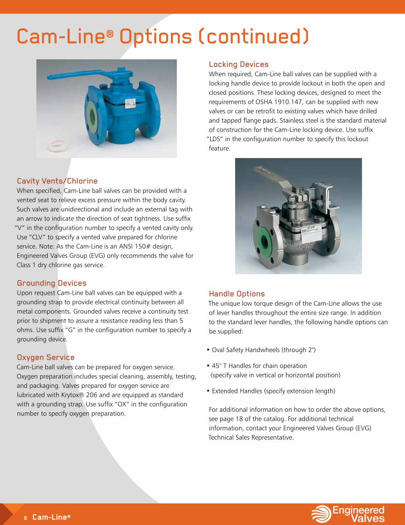
Cavity Vents/Chlorine When specified, Cam-Line ball valves can be provided with a vented seat to relieve excess pressure within the body cavity. Such valves are unidirectional and include an external tag with an arrow to indicate the direction of seat tightness. Use suffix
“V” in the configuration number to specify a vented cavity only. Use “CLV” to specify a vented valve prepared for chlorine service. Note: As the Cam-Line is an ANSI 150# design, Engineered Valves Group (EVG) only recommends the valve for Class 1 dry chlorine gas service. Grounding Devices Upon request Cam-Line ball valves can be equipped with a grounding strap to provide electrical continuity between all metal components. Grounded valves receive a continuity test prior to shipment to assure a resistance reading less than 5 ohms. Use suffix “G” in the configuration number to specify a grounding device. Oxygen Service Cam-Line ball valves can be prepared for oxygen service. Oxygen preparation includes special cleaning, assembly, testing, and packaging. Valves prepared for oxygen service are lubricated with Krytox® 206 and are equipped as standard with a grounding strap. Use suffix “OX” in the configuration number to specify oxygen preparation.
Locking Devices When required, Cam-Line ball valves can be supplied with a locking handle device to provide lockout in both the open and closed positions. These locking devices, designed to meet the requirements of OSHA 1910.147, can be supplied with new valves or can be retrofit to existing valves which have drilled and tapped flange pads. Stainless steel is the standard material of construction for the Cam-Line locking device. Use suffix
“LDS” in the configuration number to specify this lockout feature.
Handle Options The unique low torque design of the Cam-Line allows the use of lever handles throughout the entire size range. In addition to the standard lever handles, the following handle options can be supplied:
• Oval Safety Handwheels (through 2")
• 45° T Handles for chain operation (specify valve in vertical or horizontal position)
• Extended Handles (specify extension length) For additional information on how to order the above options, see page 18 of the catalog. For additional technical information, contact your Engineered Valves Group (EVG) Technical Sales Representative.
Cam-Line® 9
Cam-Line® Options (continued) Actuated ValvesWith its simple, 90 degree rotation, the Cam-Line ball valve can be easily supplied with a variety of quarter-turn operators for automated valve service. Utilizing flange pads for actuator mounting, the low torque design of the Cam-Line allows smaller, less costly actuation devices to be employed.
Another advantage of actuating the Cam-Line comes from the camming action of the ball. Since there is virtually no load on the seats when the valve is in the open position, there is no high “breakaway torque” associated with beginning the closing cycle. The actuator is able to start motion from the open position with little resistance. Only when the valve is essentially closed does the actuator see the design torque of the valve. This operation is extremely beneficial for “fail closed” valves in hostile service conditions.
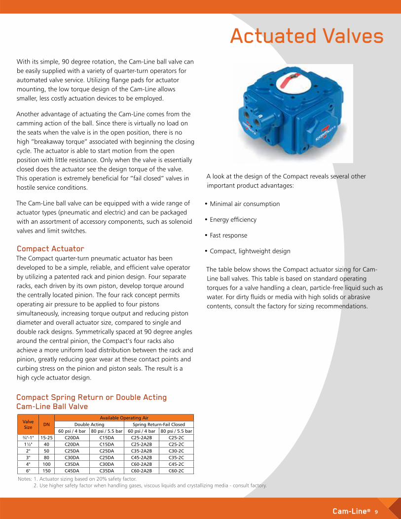
The Cam-Line ball valve can be equipped with a wide range of actuator types (pneumatic and electric) and can be packaged with an assortment of accessory components, such as solenoid valves and limit switches. Compact Actuator The Compact quarter-turn pneumatic actuator has been developed to be a simple, reliable, and efficient valve operator by utilizing a patented rack and pinion design. Four separate racks, each driven by its own piston, develop torque around the centrally located pinion. The four rack concept permits operating air pressure to be applied to four pistons simultaneously, increasing torque output and reducing piston diameter and overall actuator size, compared to single and double rack designs. Symmetrically spaced at 90 degree angles around the central pinion, the Compact’s four racks also achieve a more uniform load distribution between the rack and pinion, greatly reducing gear wear at these contact points and curbing stress on the pinion and piston seals. The result is a high cycle actuator design.
A look at the design of the Compact reveals several other important product advantages:
• Minimal air consumption
• Energy efficiency
• Fast response
• Compact, lightweight design The table below shows the Compact actuator sizing for Cam-Line ball valves. This table is based on standard operating torques for a valve handling a clean, particle-free liquid such as water. For dirty fluids or media with high solids or abrasive contents, consult the factory for sizing recommendations.
Compact Spring Return or Double Acting Cam-Line Ball Valve
Valve Size DN
Available Operating AirDouble Acting Spring Return-Fail Closed
60 psi / 4 bar 80 psi / 5.5 bar 60 psi / 4 bar 80 psi / 5.5 bar¾"-1" 15-25 C20DA C15DA C25-2A2B C25-2C1½" 40 C20DA C15DA C25-2A2B C25-2C2" 50 C25DA C25DA C35-2A2B C30-2C3" 80 C30DA C25DA C45-2A2B C35-2C4" 100 C35DA C30DA C60-2A2B C45-2C6" 150 C45DA C35DA C60-2A2B C60-2C
Notes: 1. Actuator sizing based on 20% safety factor. 2. Use higher safety factor when handling gases, viscous liquids and crystallizing media - consult factory.
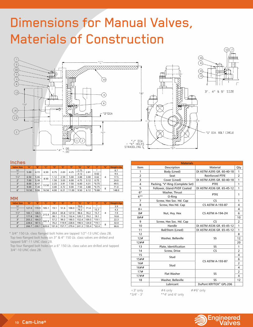
Dimensions for Manual Valves, Materials of Construction
10 Cam-Line®
Valve Size "A" "B" "C" "D" "E" "F" "G" "H" "J" "K" Weight-Lbs¾"
5.00 4.72 6.50 0.75 2.03 4.252.75
2.81*
4
8.71" 3.12 0.62 9.5
1½" 6.50 5.068.50
1.12 2.59 5.00 3.88 3.00 0.62 17.52" 7.00 5.38 1.50 3.03 6.00 4.75 3.12 0.75 24.03" 8.00 6.47
13.502.25 3.91 7.50 6.00 4.31 *0.75 49.5
4" 9.00 7.38 3.00 4.72 9.00 7.50 4.88 *0.758
71.06" 10.50 9.06 16.56 4.00 6.21 11.00 9.50 6.12 *0.88 148.0
Inches
Valve Size "A" "B" "C" "D" "E" "F" "G" "H" "J" "K" Weight-Kgs¾"
127.0 119.9 165.1 19.1 51.6 108.070.0
71.4*
4
3.91" 79.2 15.7 4.3
1½" 165.1 128.5215.9
28.4 65.8 127.0 98.6 76.2 15.7 7.92" 177.8 136.7 38.1 77.0 152.4 120.7 79.2 19.1 10.83" 203.2 164.3
342.957.2 99.3 190.5 152.4 109.5 *19.1 22.3
4" 228.6 187.5 76.2 119.9 228.6 190.5 124.0 *19.18
32.06" 266.7 230.1 420.6 101.6 157.7 279.4 241.3 155.4 *22.4 66.6
MM
MaterialsItem Description Material Qty
1 Body (Lined) DI ASTM A395 GR. 60-40-18 12 Seat Reinforced PTFE 23 Cover (Lined) DI ASTM A395 GR. 60-40-18 14 Packing, "V"-Ring (Complete Set) PTFE 15 Follower, Gland-PVDF Coated DI ASTM A536 GR. 65-45-12 16* Washer, Thrust
PTFE 16** O-Ring7 Screw, Hex Soc. Hd. Cap CS 18 Screw, Hex Hd. Cap CS ASTM A-193-B7 4
8+Nut, Hvy. Hex CS ASTM A-194-2H
48# 6
8## 109 Screw, Hex Soc. Hd. Cap CS 2
10 Handle DI ASTM A536 GR. 65-45-12 111 Ball/Stem (Lined) DI ASTM A536 GR. 65-45-12 112
Washer, Belleville SS8
12# 1212## 20
13 Plate, Identification SS 114 Screw, Drive CS 215
StudCS ASTM A-193-B7
415## 616#
Stud2
16## 417#
Flat Washer SS2
17## 418 Washer, Belleville SS 12
Lubricant DuPont KRYTOX® GPL-206
* 3/4” 150 Lb. class flanged bolt holes are tapped 1/2”-13 UNC class 2B. Top two flanged bolt holes on 3” & 4” 150 Lb. class valves are drilled and tapped 5/8”-11 UNC class 2B. Top four flanged bolt holes on a 6” 150 Lb. class valve are drilled and tapped 3/4”-10 UNC class 2B.
+3" only #4 only ##6" only *3/4" - 3" **4" and 6" only
Dimensions for Manual Valves, Materials of Construction
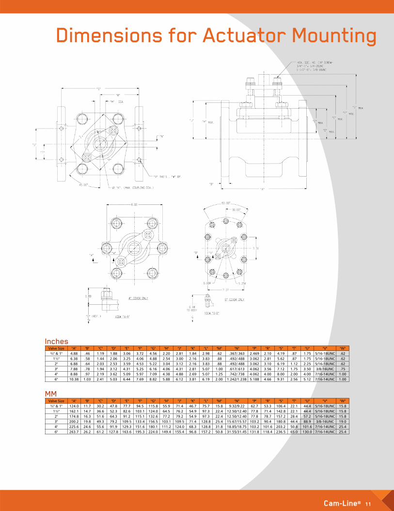
Dimensions for Actuator Mounting
Cam-Line® 11
Valve Size "A" "B" "C" "D" "E" "F" "G" "H" "J" "K" "L" "M" "N" "P" "R" "S" "T" "U" "V" "W"¾" & 1" 4.88 .46 1.19 1.88 3.06 3.72 4.56 2.20 2.81 1.84 2.98 .62 .367/.363 2.469 2.10 4.19 .87 1.75 5/16-18UNC .62
1½" 6.38 .58 1.44 2.06 3.25 4.06 4.88 2.54 3.00 2.16 3.83 .88 .492/.488 3.062 2.81 5.62 .87 1.75 5/16-18UNC .622" 6.88 .64 2.03 2.53 3.59 4.53 5.22 3.04 3.12 2.16 3.83 .88 .492/.488 3.062 3.10 6.19 1.12 2.25 5/16-18UNC .623" 7.88 .78 1.94 3.12 4.31 5.25 6.16 4.06 4.31 2.81 5.07 1.00 .617/.613 4.062 3.56 7.12 1.75 3.50 3/8-16UNC .754" 8.88 .97 2.19 3.62 5.09 5.97 7.09 4.38 4.88 2.69 5.07 1.25 .742/.738 4.062 4.00 8.00 2.00 4.00 7/16-14UNC 1.006" 10.38 1.03 2.41 5.03 6.44 7.69 8.82 5.88 6.12 3.81 6.19 2.00 1.242/1.238 5.188 4.66 9.31 2.56 5.12 7/16-14UNC 1.00
Inches
Valve Size "A" "B" "C" "D" "E" "F" "G" "H" "J" "K" "L" "M" "N" "P" "R" "S" "T" "U" "V" "W"¾" & 1" 124.0 11.7 30.2 47.8 77.7 94.5 115.8 55.9 71.4 46.7 75.7 15.8 9.32/9.22 62.7 53.3 106.4 22.1 44.4 5/16-18UNC 15.8
1½" 162.1 14.7 36.6 52.3 82.6 103.1 124.0 64.5 76.2 54.9 97.3 22.4 12.50/12.40 77.8 71.4 142.8 22.1 44.4 5/16-18UNC 15.82" 174.8 16.3 51.6 64.3 91.2 115.1 132.6 77.2 79.2 54.9 97.3 22.4 12.50/12.40 77.8 78.7 157.2 28.4 57.2 5/16-18UNC 15.83" 200.2 19.8 49.3 79.2 109.5 133.4 156.5 103.1 109.5 71.4 128.8 25.4 15.67/15.57 103.2 90.4 180.8 44.4 88.9 3/8-16UNC 19.04" 225.6 24.6 55.6 91.9 129.3 151.6 180.1 111.2 124.0 68.3 128.8 31.8 18.85/18.75 103.2 101.6 203.2 50.8 101.6 7/16-14UNC 25.46" 263.7 26.2 61.2 127.8 163.6 195.3 224.0 149.4 155.4 96.8 157.2 50.8 31.55/31.45 131.8 118.4 236.5 65.0 130.0 7/16-14UNC 25.4
MM
12 Cam-Line®
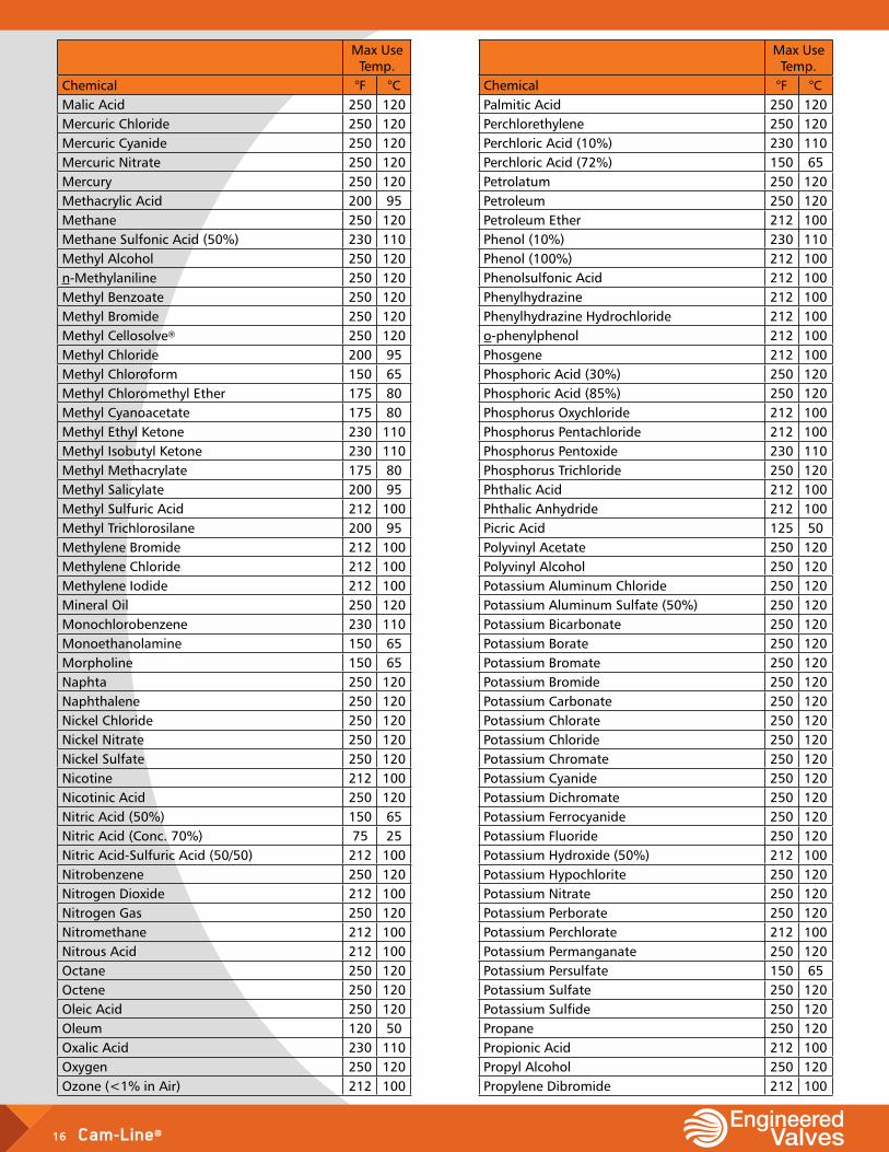
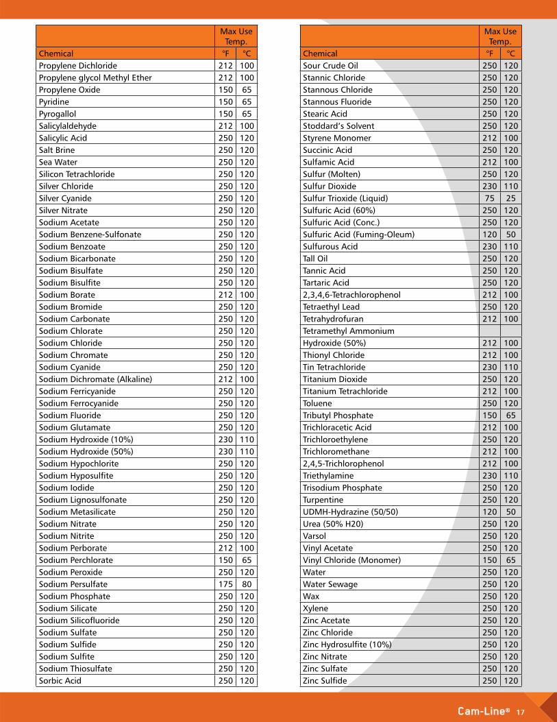
Service GuideFor ultimate exterior corrosion protection in aggressive chemical environments, Cam-Line ball valves can be externally coated with PVDF. A popular feature of the Dia-Flo® Diaphragm Valve, this optional 6–8 mil coating is applied to all ductile iron components of the Cam-Line prior to the valve being lined. The result is a mechanically tough coating that is resistant to spills, splash, and corrosive atmospheres at temperatures to 200° F. ETFE lined Cam-Line ball valves coated with PVDF are equipped with stainless steel fasteners to enhance total corrosion resistance.
Data, recommendations, and suggestions contained herein are based on experiences in actual field applications as well as common corrosion data. However, because of so many possible variances in practices from plant to plant, these recommendations are intended for use only as a guide and should not be interpreted as a guarantee.
Selections in the following pages have been made with safety and serviceability as the foremost considerations.
Many variables enter into the question of serviceability. Factors such as concentration, temperature, pressure, velocity, percent solids, temperature cycling, vacuum, cleaning practices, etc. are all important in determining whether or not a particular material will give satisfactory service.
Of the endless number of chemical compounds many are insoluble in water and would consequently cause no corrosion problems when in water. However, some of these simple services can become difficult when it is necessary to make such materials soluble through use of some other solvent. For example, sulfuric acid is commonly used as a solvent for silver chloride. Then the recommendation must take into account both silver chloride and sulfuric acid. As a general rule, it is recommended that pipeline or tank material be used for the valve body whenever possible.
Engineered Valves cannot accept responsibility for the accuracy, currency or reliability of the information contained herein. Selection of materials is at the sole risk of the user. Consult factory for services not listed.
Cam-Line® 13
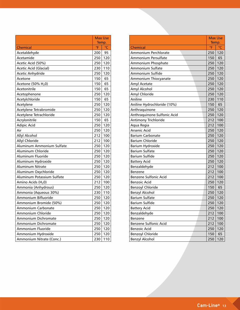
Max Use Temp.
Chemical °F °CAcetaldehyde 200 95Acetamide 250 120Acetic Acid (50%) 250 120Acetic Acid (Glacial) 230 110Acetic Anhydride 250 120Acetone 150 65Acetone (50% H²0) 150 65Acetonitrile 150 65Acetophenone 250 120Acetylchloride 150 65Acetylene 250 120Acetylene Tetrabromide 250 120Acetylene Tetrachloride 250 120Acrylonitrile 150 65Adipic Acid 250 120Air 250 120Allyl Alcohol 212 100Allyl Chloride 212 100Aluminum Ammonium Sulfate 250 120Aluminum Chloride 250 120Aluminum Fluoride 250 120Aluminum Hydroxide 250 120Aluminum Nitrate 250 120Aluminum Oxychloride 250 120Aluminum Potassium Sulfate 250 120Amino Acids (H²0) 212 100Ammonia (Anhydrous) 250 120Ammonia (Aqueous 30%) 230 110Ammonium Bifluoride 250 120Ammonium Bromide (50%) 250 120Ammonium Carbonate 250 120Ammonium Chloride 250 120Ammonium Dichromate 250 120Ammonium Dichromate 250 120Ammonium Fluoride 250 120Ammonium Hydroxide 250 120Ammonium Nitrate (Conc.) 230 110
Max Use Temp.
Chemical °F °CAmmonium Perchlorate 250 120Ammonium Persulfate 150 65Ammonium Phosphate 250 120Ammonium Sulfate 250 120Ammonium Sulfide 250 120Ammonium Thiocyanate 250 120Amyl Acetate 250 120Amyl Alcohol 250 120Amyl Chloride 250 120Aniline 230 110Aniline Hydrochloride (10%) 150 65Anthraquinone 250 120Anthraquinone-Sulfonic Acid 250 120Antimony Trichloride 212 100Aqua Regia 212 100Arsenic Acid 250 120Barium Carbonate 250 120Barium Chloride 250 120Barium Hydroxide 250 120Barium Sulfate 250 120Barium Sulfide 250 120Battery Acid 250 120Benzaldehyde 212 100Benzene 212 100Benzene Sulfonic Acid 212 100Benzoic Acid 250 120Benzoyl Chloride 150 65Benzyl Alcohol 250 120Barium Sulfate 250 120Barium Sulfide 250 120Battery Acid 250 120Benzaldehyde 212 100Benzene 212 100Benzene Sulfonic Acid 212 100Benzoic Acid 250 120Benzoyl Chloride 150 65Benzyl Alcohol 250 120
14 Cam-Line®
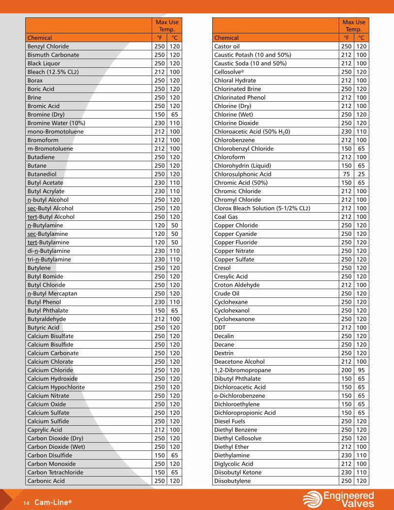
Max Use Temp.
Chemical °F °CBenzyl Chloride 250 120Bismuth Carbonate 250 120Black Liquor 250 120Bleach (12.5% CL2) 212 100Borax 250 120Boric Acid 250 120Brine 250 120Bromic Acid 250 120Bromine (Dry) 150 65Bromine Water (10%) 230 110mono-Bromotoluene 212 100Bromoform 212 100m-Bromotoluene 212 100Butadiene 250 120Butane 250 120Butanediol 250 120Butyl Acetate 230 110Butyl Acrylate 230 110n-butyl Alcohol 250 120sec-Butyl Alcohol 250 120tert-Butyl Alcohol 250 120n-Butylamine 120 50sec-Butylamine 120 50tert-Butylamine 120 50di-n-Butylamine 230 110tri-n-Butylamine 230 110Butylene 250 120Butyl Bomide 250 120Butyl Chloride 250 120n-Butyl Mercaptan 250 120Butyl Phenol 230 110Butyl Phthalate 150 65Butyraldehyde 212 100Butyric Acid 250 120Calcium Bisulfate 250 120Calcium Bisulfide 250 120Calcium Carbonate 250 120Calcium Chlorate 250 120Calcium Chloride 250 120Calcium Hydroxide 250 120Calcium Hypochlorite 250 120Calcium Nitrate 250 120Calcium Oxide 250 120Calcium Sulfate 250 120Calcium Sulfide 250 120Caprylic Acid 212 100Carbon Dioxide (Dry) 250 120Carbon Dioxide (Wet) 250 120Carbon Disulfide 150 65Carbon Monoxide 250 120Carbon Tetrachloride 150 65Carbonic Acid 250 120
Max Use Temp.
Chemical °F °CCastor oil 250 120Caustic Potash (10 and 50%) 212 100Caustic Soda (10 and 50%) 212 100Cellosolve® 250 120Chloral Hydrate 212 100Chlorinated Brine 250 120Chlorinated Phenol 212 100Chlorine (Dry) 212 100Chlorine (Wet) 250 120Chlorine Dioxide 250 120Chloroacetic Acid (50% H²0) 230 110Chlorobenzene 212 100Chlorobenzyl Chloride 150 65Chloroform 212 100Chlorohydrin (Liquid) 150 65Chlorosulphonic Acid 75 25Chromic Acid (50%) 150 65Chromic Chloride 212 100Chromyl Chloride 212 100Clorox Bleach Solution (5-1/2% CL2) 212 100Coal Gas 212 100Copper Chloride 250 120Copper Cyanide 250 120Copper Fluoride 250 120Copper Nitrate 250 120Copper Sulfate 250 120Cresol 250 120Cresylic Acid 250 120Croton Aldehyde 212 100Crude Oil 250 120Cyclohexane 250 120Cyclohexanol 250 120Cyclohexanone 250 120DDT 212 100Decalin 250 120Decane 250 120Dextrin 250 120Deacetone Alcohol 212 1001,2-Dibromopropane 200 95Dibutyl Phthalate 150 65Dichloroacetic Acid 150 65o-Dichlorobenzene 150 65Dichloroethylene 150 65Dichloropropionic Acid 150 65Diesel Fuels 250 120Diethyl Benzene 250 120Diethyl Cellosolve 250 120Diethyl Ether 212 100Diethylamine 230 110Diglycolic Acid 212 100Diisobutyl Ketone 230 110Diisobutylene 250 120
Cam-Line® 15
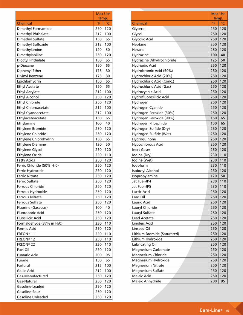
Max Use Temp.
Chemical °F °CDimethyl Formamide 250 120Dimethyl Phthalate 212 100Dimethyl Sulfate 150 65Dimethyl Sulfoxide 212 100Dimethylamine 120 50Dimethylaniline 250 120Dioctyl Phthalate 150 65p-Dioxane 150 65Diphenyl Ether 175 80Divinyl Benzene 175 80Epichlorhydrin 150 65Ethyl Acetate 150 65Ethyl Acrylate 212 100Ethyl Alcohol 250 120Ethyl Chloride 250 120Ethyl Chloroacetate 212 100Ethyl Cyanoacetate 212 100Ethylacetoacetate 150 65Ethylamine 100 40Ethylene Bromide 250 120Ethylene Chloride 250 120Ethylene Chlorohydrin 150 65Ethylene Diamine 120 50Ethylene Glycol 250 120Ethylene Oxide 230 110Fatty Acids 250 120Ferric Chloride (50% H²0) 250 120Ferric Hydroxide 250 120Ferric Nitrate 250 120Ferric Sulfate 250 120Ferrous Chloride 250 120Ferrous Hydroxide 250 120Ferrous Nitrate 250 120Ferrous Sulfate 250 120Fluorine (Gaseous) 100 40Fluoroboric Acid 250 120Fluosilicic Acid 250 120Formaldehyde (37% in H²0) 230 110Formic Acid 250 120FREON® 11 230 110FREON® 12 230 110FREON® 22 230 110Fuel Oil 250 120Fumaric Acid 200 95Furane 150 65Furfural 212 100Gallic Acid 212 100Gas-Manufactured 250 120Gas-Natural 250 120Gasoline-Leaded 250 120Gasoline-Sour 250 120Gasoline Unleaded 250 120
Max Use Temp.
Chemical °F °CGlycerol 250 120Glycol 250 120Glycolic Acid 250 120Heptane 250 120Hexane 250 120Hydrazine 100 40Hydrazine Dihydrochloride 125 50Hydriodic Acid 250 120Hydrobromic Acid (50%) 250 120Hydrochloric Acid (20%) 250 120Hydrochloric Acid (Conc.) 250 120Hydrochloric Acid (Gas) 250 120Hydrocyanic Acid 250 120Hydrofluorosilicic Acid 250 120Hydrogen 250 120Hydrogen Cyanide 250 120Hydrogen Peroxide (30%) 250 120Hydrogen Peroxide (90%) 150 65Hydrogen Phosphide 150 65Hydrogen Sulfide (Dry) 250 120Hydrogen Sulfide (Wet) 250 120Hydroquinone 250 120Hypochlorous Acid 250 120Inert Gases 250 120Iodine (Dry) 230 110Iodine (Wet) 230 110Iodoform 230 110Isobutyl Alcohol 250 120Isopropylamine 120 50Jet Fuel-JP4 230 110Jet Fuel-JP5 230 110Lactic Acid 250 120Lard Oil 250 120Lauric Acid 250 120Lauryl Chloride 250 120Lauryl Sulfate 250 120Lead Acetate 250 120Linoleic Acid 250 120Linseed Oil 250 120Lithium Bromide (Saturated) 250 120Lithium Hydroxide 250 120Lubricating Oil 250 120Magnesium Carbonate 250 120Magnesium Chloride 250 120Magnesium Hydroxide 250 120Magnesium Nitrate 250 120Magnesium Sulfate 250 120Maleic Acid 250 120Maleic Anhydride 200 95
16 Cam-Line®
Max Use Temp.
Chemical °F °CMalic Acid 250 120Mercuric Chloride 250 120Mercuric Cyanide 250 120Mercuric Nitrate 250 120Mercury 250 120Methacrylic Acid 200 95Methane 250 120Methane Sulfonic Acid (50%) 230 110Methyl Alcohol 250 120n-Methylaniline 250 120Methyl Benzoate 250 120Methyl Bromide 250 120Methyl Cellosolve® 250 120Methyl Chloride 200 95Methyl Chloroform 150 65Methyl Chloromethyl Ether 175 80Methyl Cyanoacetate 175 80Methyl Ethyl Ketone 230 110Methyl Isobutyl Ketone 230 110Methyl Methacrylate 175 80Methyl Salicylate 200 95Methyl Sulfuric Acid 212 100Methyl Trichlorosilane 200 95Methylene Bromide 212 100Methylene Chloride 212 100Methylene Iodide 212 100Mineral Oil 250 120Monochlorobenzene 230 110Monoethanolamine 150 65Morpholine 150 65Naphta 250 120Naphthalene 250 120Nickel Chloride 250 120Nickel Nitrate 250 120Nickel Sulfate 250 120Nicotine 212 100Nicotinic Acid 250 120Nitric Acid (50%) 150 65Nitric Acid (Conc. 70%) 75 25Nitric Acid-Sulfuric Acid (50/50) 212 100Nitrobenzene 250 120Nitrogen Dioxide 212 100Nitrogen Gas 250 120Nitromethane 212 100Nitrous Acid 212 100Octane 250 120Octene 250 120Oleic Acid 250 120Oleum 120 50Oxalic Acid 230 110Oxygen 250 120Ozone (<1% in Air) 212 100
Max Use Temp.
Chemical °F °CPalmitic Acid 250 120Perchlorethylene 250 120Perchloric Acid (10%) 230 110Perchloric Acid (72%) 150 65Petrolatum 250 120Petroleum 250 120Petroleum Ether 212 100Phenol (10%) 230 110Phenol (100%) 212 100Phenolsulfonic Acid 212 100Phenylhydrazine 212 100Phenylhydrazine Hydrochloride 212 100o-phenylphenol 212 100Phosgene 212 100Phosphoric Acid (30%) 250 120Phosphoric Acid (85%) 250 120Phosphorus Oxychloride 212 100Phosphorus Pentachloride 212 100Phosphorus Pentoxide 230 110Phosphorus Trichloride 250 120Phthalic Acid 212 100Phthalic Anhydride 212 100Picric Acid 125 50Polyvinyl Acetate 250 120Polyvinyl Alcohol 250 120Potassium Aluminum Chloride 250 120Potassium Aluminum Sulfate (50%) 250 120Potassium Bicarbonate 250 120Potassium Borate 250 120Potassium Bromate 250 120Potassium Bromide 250 120Potassium Carbonate 250 120Potassium Chlorate 250 120Potassium Chloride 250 120Potassium Chromate 250 120Potassium Cyanide 250 120Potassium Dichromate 250 120Potassium Ferrocyanide 250 120Potassium Fluoride 250 120Potassium Hydroxide (50%) 212 100Potassium Hypochlorite 250 120Potassium Nitrate 250 120Potassium Perborate 250 120Potassium Perchlorate 212 100Potassium Permanganate 250 120Potassium Persulfate 150 65Potassium Sulfate 250 120Potassium Sulfide 250 120Propane 250 120Propionic Acid 212 100Propyl Alcohol 250 120Propylene Dibromide 212 100
Cam-Line® 17
Max Use Temp.
Chemical °F °CPropylene Dichloride 212 100Propylene glycol Methyl Ether 212 100Propylene Oxide 150 65Pyridine 150 65Pyrogallol 150 65Salicylaldehyde 212 100Salicylic Acid 250 120Salt Brine 250 120Sea Water 250 120Silicon Tetrachloride 250 120Silver Chloride 250 120Silver Cyanide 250 120Silver Nitrate 250 120Sodium Acetate 250 120Sodium Benzene-Sulfonate 250 120Sodium Benzoate 250 120Sodium Bicarbonate 250 120Sodium Bisulfate 250 120Sodium Bisulfite 250 120Sodium Borate 212 100Sodium Bromide 250 120Sodium Carbonate 250 120Sodium Chlorate 250 120Sodium Chloride 250 120Sodium Chromate 250 120Sodium Cyanide 250 120Sodium Dichromate (Alkaline) 212 100Sodium Ferricyanide 250 120Sodium Ferrocyanide 250 120Sodium Fluoride 250 120Sodium Glutamate 250 120Sodium Hydroxide (10%) 230 110Sodium Hydroxide (50%) 230 110Sodium Hypochlorite 250 120Sodium Hyposulfite 250 120Sodium Iodide 250 120Sodium Lignosulfonate 250 120Sodium Metasilicate 250 120Sodium Nitrate 250 120Sodium Nitrite 250 120Sodium Perborate 212 100Sodium Perchlorate 150 65Sodium Peroxide 250 120Sodium Persulfate 175 80Sodium Phosphate 250 120Sodium Silicate 250 120Sodium Silicofluoride 250 120Sodium Sulfate 250 120Sodium Sulfide 250 120Sodium Sulfite 250 120Sodium Thiosulfate 250 120Sorbic Acid 250 120
Max Use Temp.
Chemical °F °CSour Crude Oil 250 120Stannic Chloride 250 120Stannous Chloride 250 120Stannous Fluoride 250 120Stearic Acid 250 120Stoddard’s Solvent 250 120Styrene Monomer 212 100Succinic Acid 250 120Sulfamic Acid 212 100Sulfur (Molten) 250 120Sulfur Dioxide 230 110Sulfur Trioxide (Liquid) 75 25Sulfuric Acid (60%) 250 120Sulfuric Acid (Conc.) 250 120Sulfuric Acid (Fuming-Oleum) 120 50Sulfurous Acid 230 110Tall Oil 250 120Tannic Acid 250 120Tartaric Acid 250 1202,3,4,6-Tetrachlorophenol 212 100Tetraethyl Lead 250 120Tetrahydrofuran 212 100Tetramethyl AmmoniumHydroxide (50%) 212 100Thionyl Chloride 212 100Tin Tetrachloride 230 110Titanium Dioxide 250 120Titanium Tetrachloride 212 100Toluene 250 120Tributyl Phosphate 150 65Trichloracetic Acid 212 100Trichloroethylene 250 120Trichloromethane 212 1002,4,5-Trichlorophenol 212 100Triethylamine 230 110Trisodium Phosphate 250 120Turpentine 250 120UDMH-Hydrazine (50/50) 120 50Urea (50% H20) 250 120Varsol 250 120Vinyl Acetate 250 120Vinyl Chloride (Monomer) 150 65Water 250 120Water Sewage 250 120Wax 250 120Xylene 250 120Zinc Acetate 250 120Zinc Chloride 250 120Zinc Hydrosulfite (10%) 250 120Zinc Nitrate 250 120Zinc Sulfate 250 120Zinc Sulfide 250 120
18 Cam-Line®
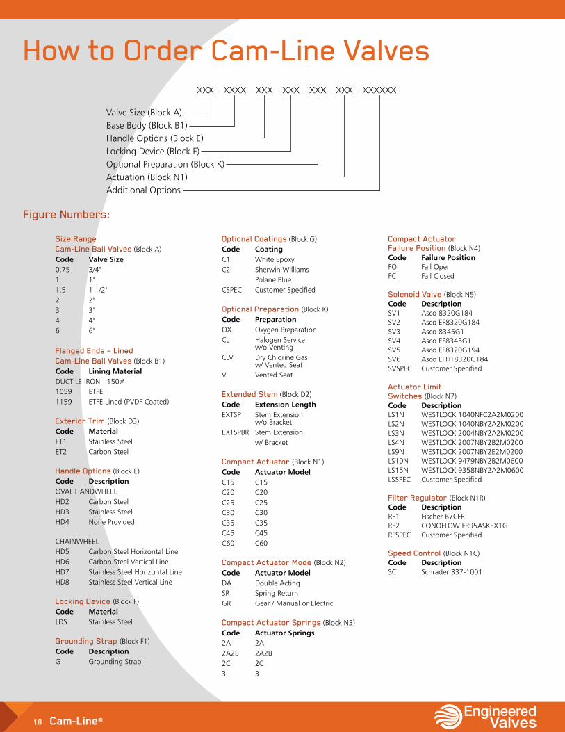
How to Order Cam-Line Valves
Optional Coatings (Block G) Code Coating C1 White Epoxy C2 Sherwin Williams Polane Blue CSPEC Customer Specified
Optional Preparation (Block K) Code Preparation OX Oxygen Preparation CL Halogen Service w/o Venting CLV Dry Chlorine Gas w/ Vented Seat V Vented Seat
Extended Stem (Block D2) Code Extension Length EXTSP Stem Extension w/o Bracket EXTSPBR Stem Extension w/ Bracket
Compact Actuator (Block N1) Code Actuator Model C15 C15 C20 C20 C25 C25 C30 C30 C35 C35 C45 C45 C60 C60
Compact Actuator Mode (Block N2) Code Actuator Model DA Double Acting SR Spring Return GR Gear / Manual or Electric
Compact Actuator Springs (Block N3) Code Actuator Springs 2A 2A 2A2B 2A2B 2C 2C 3 3
Compact Actuator Failure Position (Block N4) Code Failure Position FO Fail Open FC Fail Closed
Solenoid Valve (Block N5) Code Description SV1 Asco 8320G184 SV2 Asco EF8320G184 SV3 Asco 8345G1 SV4 Asco EF8345G1 SV5 Asco EF8320G194 SV6 Asco EFHT8320G184 SVSPEC Customer Specified
Actuator Limit Switches (Block N7) Code Description LS1N WESTLOCK 1040NFC2A2M0200 LS2N WESTLOCK 1040NBY2A2M0200 LS3N WESTLOCK 2004NBY2A2M0200 LS4N WESTLOCK 2007NBY2B2M0200 LS9N WESTLOCK 2007NBY2E2M0200 LS10N WESTLOCK 9479NBY2B2M0600 LS15N WESTLOCK 9358NBY2A2M0600 LSSPEC Customer Specified
Filter Regulator (Block N1R) Code Description RF1 Fischer 67CFR RF2 CONOFLOW FR95ASKEX1G RFSPEC Customer Specified
Speed Control (Block N1C) Code Description SC Schrader 337-1001
Size Range Cam-Line Ball Valves (Block A) Code Valve Size 0.75 3/4" 1 1" 1.5 1 1/2" 2 2" 3 3" 4 4" 6 6" Flanged Ends – Lined Cam-Line Ball Valves (Block B1) Code Lining Material DUCTILE IRON - 150# 1059 ETFE 1159 ETFE Lined (PVDF Coated)
Exterior Trim (Block D3) Code Material ET1 Stainless Steel ET2 Carbon Steel
Handle Options (Block E) Code Description OVAL HANDWHEEL HD2 Carbon Steel HD3 Stainless Steel HD4 None Provided
CHAINWHEEL HD5 Carbon Steel Horizontal Line HD6 Carbon Steel Vertical Line HD7 Stainless Steel Horizontal Line HD8 Stainless Steel Vertical Line
Locking Device (Block F) Code Material LDS Stainless Steel
Grounding Strap (Block F1) Code Description G Grounding Strap
XXX – XXXX – XXX – XXX – XXX – XXX – XXXXXX
Valve Size (Block A) Base Body (Block B1) Handle Options (Block E) Locking Device (Block F) Optional Preparation (Block K) Actuation (Block N1) Additional Options
Figure Numbers:
Cam-Line® 19
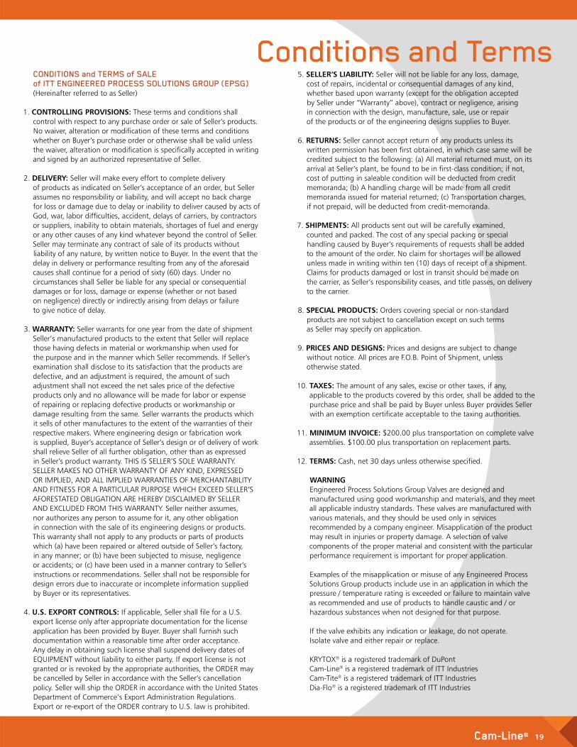
Conditions and Terms5. SELLER’S LIABILITY: Seller will not be liable for any loss, damage,
cost of repairs, incidental or consequential damages of any kind, whether based upon warranty (except for the obligation accepted by Seller under “Warranty” above), contract or negligence, arising in connection with the design, manufacture, sale, use or repair of the products or of the engineering designs supplies to Buyer.
6. RETURNS: Seller cannot accept return of any products unless its written permission has been first obtained, in which case same will be credited subject to the following: (a) All material returned must, on its arrival at Seller’s plant, be found to be in first-class condition; if not, cost of putting in saleable condition will be deducted from credit memoranda; (b) A handling charge will be made from all credit memoranda issued for material returned; (c) Transportation charges, if not prepaid, will be deducted from credit-memoranda.
7. SHIPMENTS: All products sent out will be carefully examined, counted and packed. The cost of any special packing or special handling caused by Buyer’s requirements of requests shall be added to the amount of the order. No claim for shortages will be allowed unless made in writing within ten (10) days of receipt of a shipment. Claims for products damaged or lost in transit should be made on the carrier, as Seller’s responsibility ceases, and title passes, on delivery to the carrier.
8. SPECIAL PRODUCTS: Orders covering special or non-standard products are not subject to cancellation except on such terms as Seller may specify on application.
9. PRICES AND DESIGNS: Prices and designs are subject to change without notice. All prices are F.O.B. Point of Shipment, unless otherwise stated.
10. TAXES: The amount of any sales, excise or other taxes, if any, applicable to the products covered by this order, shall be added to the purchase price and shall be paid by Buyer unless Buyer provides Seller with an exemption certificate acceptable to the taxing authorities.
11. MINIMUM INVOICE: $200.00 plus transportation on complete valve assemblies. $100.00 plus transportation on replacement parts.
12. TERMS: Cash, net 30 days unless otherwise specified.
WARNING Engineered Process Solutions Group Valves are designed and manufactured using good workmanship and materials, and they meet all applicable industry standards. These valves are manufactured with various materials, and they should be used only in services recommended by a company engineer. Misapplication of the product may result in injuries or property damage. A selection of valve components of the proper material and consistent with the particular performance requirement is important for proper application.
Examples of the misapplication or misuse of any Engineered Process Solutions Group products include use in an application in which the pressure / temperature rating is exceeded or failure to maintain valve as recommended and use of products to handle caustic and / or hazardous substances when not designed for that purpose.
If the valve exhibits any indication or leakage, do not operate. Isolate valve and either repair or replace. KRYTOX® is a registered trademark of DuPont Cam-Line® is a registered trademark of ITT Industries Cam-Tite® is a registered trademark of ITT Industries Dia-Flo® is a registered trademark of ITT Industries
CONDITIONS and TERMS of SALE of ITT ENGINEERED PROCESS SOLUTIONS GROUP (EPSG) (Hereinafter referred to as Seller)
1. CONTROLLING PROVISIONS: These terms and conditions shall control with respect to any purchase order or sale of Seller’s products. No waiver, alteration or modification of these terms and conditions whether on Buyer’s purchase order or otherwise shall be valid unless the waiver, alteration or modification is specifically accepted in writing and signed by an authorized representative of Seller.
2. DELIVERY: Seller will make every effort to complete delivery of products as indicated on Seller’s acceptance of an order, but Seller assumes no responsibility or liability, and will accept no back charge for loss or damage due to delay or inability to deliver caused by acts of God, war, labor difficulties, accident, delays of carriers, by contractors or suppliers, inability to obtain materials, shortages of fuel and energy or any other causes of any kind whatever beyond the control of Seller. Seller may terminate any contract of sale of its products without liability of any nature, by written notice to Buyer. In the event that the delay in delivery or performance resulting from any of the aforesaid causes shall continue for a period of sixty (60) days. Under no circumstances shall Seller be liable for any special or consequential damages or for loss, damage or expense (whether or not based on negligence) directly or indirectly arising from delays or failure to give notice of delay.
3. WARRANTY: Seller warrants for one year from the date of shipment Seller’s manufactured products to the extent that Seller will replace those having defects in material or workmanship when used for the purpose and in the manner which Seller recommends. If Seller’s examination shall disclose to its satisfaction that the products are defective, and an adjustment is required, the amount of such adjustment shall not exceed the net sales price of the defective products only and no allowance will be made for labor or expense of repairing or replacing defective products or workmanship or damage resulting from the same. Seller warrants the products which it sells of other manufactures to the extent of the warranties of their respective makers. Where engineering design or fabrication work is supplied, Buyer’s acceptance of Seller’s design or of delivery of work shall relieve Seller of all further obligation, other than as expressed in Seller’s product warranty. THIS IS SELLER’S SOLE WARRANTY. SELLER MAKES NO OTHER WARRANTY OF ANY KIND, EXPRESSED OR IMPLIED, AND ALL IMPLIED WARRANTIES OF MERCHANTABILITY AND FITNESS FOR A PARTICULAR PURPOSE WHICH EXCEED SELLER’S AFORESTATED OBLIGATION ARE HEREBY DISCLAIMED BY SELLER AND EXCLUDED FROM THIS WARRANTY. Seller neither assumes, nor authorizes any person to assume for it, any other obligation in connection with the sale of its engineering designs or products. This warranty shall not apply to any products or parts of products which (a) have been repaired or altered outside of Seller’s factory, in any manner; or (b) have been subjected to misuse, negligence or accidents; or (c) have been used in a manner contrary to Seller’s instructions or recommendations. Seller shall not be responsible for design errors due to inaccurate or incomplete information supplied by Buyer or its representatives.
4. U.S. EXPORT CONTROLS: If applicable, Seller shall file for a U.S. export license only after appropriate documentation for the license application has been provided by Buyer. Buyer shall furnish such documentation within a reasonable time after order acceptance. Any delay in obtaining such license shall suspend delivery dates of EQUIPMENT without liability to either party. If export license is not granted or is revoked by the appropriate authorities, the ORDER may be cancelled by Seller in accordance with the Seller’s cancellation policy. Seller will ship the ORDER in accordance with the United States Department of Commerce’s Export Administration Regulations. Export or re-export of the ORDER contrary to U.S. law is prohibited.
© 2018 ITT Engineered Valves, LLC B.CLBV18.en-US.2018-04
ITT Engineered Valves: 65 Years of Providing Quality, Innovative Solutions ITT Engineered Valves has earned the reputation for delivering the highest quality, innovative valve solutions for a wide range of industrial fluid control needs. These best in-class quality valves have been the foundation for industries such as Mining, Power Generation, Pollution Control, Pulp and Paper, Chemical Processing, Water Treatment, Pharmaceutical, Food and Beverage, and Bio-Processing.
Through both standard and custom designed valve assemblies, ITT Engineered Valves is your partner in providing the best quality and value engineered solutions for your unique flow control needs.
• Dia-Flo® Diaphragm Valves
• Fabri-Valve® Knife Gate, Slide Gate, Wedge Gate and Custom-Fabricated Valves
• Cam-Tite® Hazardous and Critical Duty Ball Valves
• Cam-Line® Plastic Lined Ball Valves
• Skotch® Burner Safety Shut-Off valves
Lancaster, PA Facility
Amory, MS Facility
Engineered Valves, LLC33 Centerville RoadLancaster, PA 176031717.509.2200www.engvalves.com
ITT Industries Ltd.Weycroft Avenue, Millwey Rise Industrial EstateAxminster, EX13 5HU United Kingdom Tel: +44 1297-639100 Fax: +44 1297-630476
Engineered Valves, LLC1110 Bankhead AvenueAmory, MS 38821662.256.7185www.engvalves.com