Embed Size (px)
Citation preview

CAM Final Project
Due: 05/02/07 Pedals
Clutch Cover License Plate Screwdriver
To: John Irwin From:
JJ MacNeil Nolan Osborne
Pat Mclean

Objectives:
1) Design parts in Unigraphics. 2) Utilize the Computer Aided Manufacturing application in Unigraphics to
create and post process a program with multiple operations such as drilling, facing and profiling.
3) Become familiar with creating a fixture to hold the work piece. 4) Learn the functions on the control panel on the Haas machine. 5) Know how to power up the Haas machine, set tool offsets, load/change tools,
load the work piece, locate the work piece, load a program on the machine, and lastly how to safely execute the program.
6) Learn the operation and functions of the Primo Lathe to complete our desired parts.
Order of Operations: Pedals-
1) Peck Drilling using 5/16 HSS drill bit 2) Planar Mill using 1/8 HSS end mill 3) Z- Level profile 1/8 HSS end mill
Clutch Cover-
1) Cavity Mill using 5/16 HSS end mill 2) Facing Lathe using carbide insert 55˚.
License Plate-
1) Cavity Mill Finish using ¼ inch end mill 2) Cavity Mill finish using ¼ inch end mill 3) Cavity Mill Finish using 1/8 inch end mill 4) Z_Level profile using 1/8 inch end mill 5) Z_Level profile using 1/4 inch end mill
Billet Screwdriver- 1) Contour Lathe Turning using carbide insert 55˚ 2) Z- Level profile 1/4 HSS end mill 3) Cavity Mill using 5/16 HSS ball mill

Background: Pedals- The pedals that I made out of aluminum stock are for the MTU Mini-Baja Enterprise that I am on. I made two pedals, one for the brake and the reverse design for the gas. Pedals normally on the Mini-Baja team are made from 1/8” sheet metal with holes pressed through them for traction. This design will be a lot lighter and more attractive to the eye. After I cut this design out of the mill I will get the brake pedal anodized red and the gas pedal anodized green to further increase our points from judges at the competition. Clutch Cover-
I also machined our P-90 primary clutch for our baja car; I machined both inner and outer sheeve to resurface it for the belt to have a smooth surface to ride on. Lastly I cut a design out of the front cover of the primary clutch for aesthetics and weight reduction. This was done because the current primary clutch we use for mini-baja is over designed for our purposes. These P-90 clutches are usually run at an RPM exceeding 8000 and we never reach 3500 RPM. Billet Screwdriver-
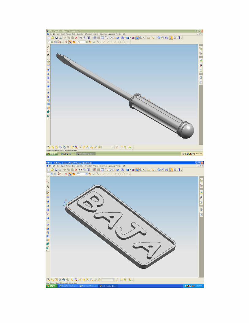
The simple flat head screwdriver is a very common hand tool that can be found in almost every household in the country. This tool was selected to be manufactured for this project because of the complexity of the operations that have to be performed as well as the usefulness of the part. This flat head screwdriver was made out of a solid piece of stainless steel round stock. Typically screwdrivers consist of a plastic handle, steel shaft and a heat-treated tip to prevent it from shearing off under loaded conditions. If time and resources allowed, heat treatment would be a nice touch to this project in order to make the part completely functional. The simple screwdriver seems rather straightforward to manufacture, yet the process includes one turning operation and two milling operations. As shown in the figure below, the process for making a flat-head screwdriver in nothing like the process being used to create the screwdriver in this project. The actual process begins with steel wire being drawn through machine that comes out to the right diameter for the shaft. The second process involves annealing the metal or heat-treating it. The third is a process used to straighten the metal. Next, the metal is cold formed to the correct shape, including the tip. Finally screwdrivers are typically nickel plated to further protect and strengthen them. The

standard screwdriver and screw sizes were researched and we decided to make the tip .035 in. thick and .210 in. long—the average size of a screwdriver and screw. In order for the handle to be ergonomic, the 4 in. handle is made to fit in the average man’s hand. To make the screwdriver more comfortable, the handle diameter is .100 in smaller than either end of the handle allowing more stability when turning a screw. As for handle grip, six ball end grooves will be milled into the handle. There are no sharp corners/radii for two reasons: 1) safety, and 2) so that there are no stress concentrations which could cause failure of the part when trying to release those hard-to-loosen screws. This screwdriver follows the same basic design as household versions, yet the material and processes used to create this screwdriver make is unique. License Plate-
The license plate was originally a project for the mini-Baja team to include on their car as a show piece. We wanted to do a trial run with aluminum to see how it looked and then maybe if it looked good we wanted to machine a plate in brass. Data Gathering:
1) Unigraphics 2) 3 1/2 inch floppy disk 3) P-90 Primary Polaris Clutch 4) Calipers 5) Primo Lathe 6) Edge Finder 7) Calculator 8) Haas Mill 9) Cut off tool 10) .25 inch aluminum flat stock (6” x 10”)
Two pieces 11) 14” long 1” stainless steel round stock 12) Drill bits 13) ¼” end mill, 1/8” end mill 14) Sandvik Tool inserts 15) 5/16 in. ball mill

Methods: Pedals and Clutch Cover-
1) Purchase .25” aluminum plate and cut to roughly 6” x 6” and the clutch cover is off of the current primary clutch for mini-baja.
2) Draw the parts in unigraphics and choose the proper machining methods and tools. Then post-process the parts to a floppy disk to get the G-code.
3) Figure out the required speeds and feeds based on the material, cutters, and diameter of the cutters.
4) Turn on the HAAS mill and check for low coolant and any signs of damage. 5) Download the G-code onto the HAAS mill interface and bring it into the
program screen. Insure all necessary fixes are made to the program to insure smooth operation.
6) Load all necessary tools for the parts to be cut and ensure the proper tool sizes.
7) Zero out the X, Y, and Z axis using the edge finder and a 0.2”offset compensator.
8) Perform a dry run either in the air or on a piece of machinists wax to ensure that the code has been properly transferred and that no abrupt cuts will be made.
9) Clamp down the plate stock with clamps and make sure they don’t interfere with the path of the tool.
10) The MCS is located in the lower left hand corner of the plate so when the parts are zeroed out that should be kept in mind. For the clutch cover it is located in the center slide hole.
11) The part should be fixtured with four clamps, one on each corner and for the cover it should be fastened to a piece of aluminum so that it can be clamped in the vice.
12) After the last tool path the parts will not be totally free from the stock, so it needs to be pressed out and the burrs removed.
License Plate-
1) Purchase .25” aluminum plate and cut to roughly 12” x 12” for a relative size 2) Draw the part in unigraphics and choose the proper machining methods and
tools. Then post-process the part to a floppy to get the G-code. 3) Figure out the required speeds and feeds based on the material, cutters, and
diameter of the cutters. 4) Turn on the HAAS mill and check for low coolant and any signs of damage. 5) Download the G-code onto the HAAS mill interface and bring it into the
program screen. 6) Load all necessary tools for the part to be cut and ensure the proper tool sizes. 7) Zero out the X, Y, and Z axis. 8) Perform a dry run either in the air or on a piece of machinists wax to ensure
that the code has been properly transferred.

9) Clamp down the plate stock with clamps and make sure they don’t interfere with the path of the tool. The last tool path includes performing a Z level profile cut to cut the plate out of the piece of stock so be aware of that.
10) The MCS is located in the lower left hand corner of the plate so when the parts are zeroed out that should be kept in mind.
11) The part should be fixtured with four clamps, one on each corner. 12) After the last tool path the part will not be totally free from the stock, so it
needs to be pressed out and the burrs removed. Billet Screwdriver- The lathe operation methods include:
1) Model screwdriver in Unigraphics and create drawing including all diameters and the lengths from one end
2) Draw the contour on the lathe computer using the drawing created in Unigraphics
3) Select a tool holder and insert based on the radii needed and tool material 4) Set part zero and tool offsets 5) Drill hole in center and set up live-centered tail stock 6) Run the first program 7) Turn the part around, resetting the part zero 8) Run the second lathe program
The Milling operation methods include: 1) Create and post process operations in Unigraphics 2) Download program on to the Haas controller 3) Set up part in fixture 4) Load the tool (1/4” end mill) in the tool holder 5) Set the work offsets and the tool offsets 6) Run the z-level profile program 7) Change tool to 5/16 ball mill 8) Re-measure tool offsets 9) Run the program for the groove 10) Repeat the groove program 4 subsequent times after indexing the part 90
degrees each time Analysis and Results: Screwdriver-
The turning operation for the lathe was done at a constant surface speed as recommended by the Sanvik tool insert for cutting stainless steel. Table one below shows an estimate of the contour of the screwdriver that was programmed into the lathe computer. Table 2 shows the speeds associated with the constant feed of 100 surface feet per minute. Because the feed was kept constant, the spindle speed changed as the diameter being cut changed. Table 2 shows only the spindle speeds at the final contour, but there was much more variation in the speed (rpm) as the part was being turned down. As you can see, the speeds are inversely related to the radii of the part. As the part gets smaller in circumference, the spindle has to speed up in order to hold the constant surface

speed of 100 feet per minute. The speeds are only theoretically infinity at the radius of zero, but realistically, the machine is running its maximum spindle speed at these points. Table 3 in appendix 1 shows the speed and feed calculations done using an excel spreadsheet. The average spindle speeds that were used were 700-800 RPM.
Outline of Part
0
0.1
0.2
0.3
0.4
0.5
0.6
0 2 4 6 8 10
Length from Datum End (in)
Rad
ius
(in)
12
Figure 1: Screwdriver part contour
Spindle Speeds
0
200
400
600
800
1000
1200
1400
0 2 4 6 8 10 12
Length From Datum End (in)
Spin
dle
Spee
d (r
pm)
14
Figure 2: Lathe spindle speeds for screwdriver For the milling operations, we used the calculator on the Haas controller. We
entered the material type, the cutter information, and the depth of cut and the recommended speed was about 700rpm and a feed of 4 inches per minute. These are relatively slow speeds and feeds mainly due to the fact that the material being cut is stainless steel which is much harder that the typical aluminum we are used to dealing with. Also the tool material type is an important factor in determining the speeds and feeds and since the cutter is High Speed Steel as opposed to carbide, this contributes to the slow speeds and feeds. For the z-level profile cut we took eight passes with small depths of cut because of the tendency to chatter, but with the ball mill operation we ran each groove in one pass taking .125” off the material.

Discussion: License Plate-
The original license plate was going to include two separate plates; one that said baja on it and one with the name jack on it. The plates had several different operations included in the machine programs. The first time the license plate was modeled up, it was done with a mill planar operation. The machining methods in this operation were in mill planar and included three sub-operations. The first sub- operation was a face mill and cut the inside edges of the part and around the letters. The second operation was also a face mill and included the biggest material removal from the inside edges of the part to the letters. The third and final operation cut the plate out from the plate material with a Z level profile. The programs were verified fine with these plates. The one detail that didn’t work on the jack plate was that on the final operation, the tool wouldn’t cut all the way through the plate material. This detail could be corrected by resetting your Z offsets when you get to the final operation. These programs were post processed but they were never put to use on the HAAS because it was suggested to try to delete the second operation because it was not needed. When the second operation was deleted, the plates would not verify correctly so the machining methods had to be redone.
The second try at setting up the machining methods was the one in which the baja plate was cut out. The operation chosen for this was a cavity mill operation. This actually involved using five separate operations; three cavity milling operations and then two Z level profile milling operations. The first two cavity mills were done using a ¼ inch end mill within boundaries drawn on the plate above and below the text. The third cavity milling operation used a 1/8 inch end mill to cut around the text itself. The first Z-level profile was done to touch up the text on the plate using a 1/8 inch end mill. The final Z level operation included cutting out the part with a ¼ inch end mill. This operation had some minor flaws that didn’t show on the tool path verification. On the two upper corners, the first cavity mill operation made some small divots. The reason the divots were cut is because the rectangles that were used as boundaries were not close enough to the part itself so the machine had to make and extra pass outside of the part. The other flaw in the program occurred when the machine went to cut the plate out of the plate material. Instead of switching from a 1/8 end mill to a ¼ inch end mill like was specified, the machined jammed the 1/8 inch mil into the material and broke the cutter.
After the part was cut out, the boundaries were changed, but the part would not regenerate correctly and due to time constraints was not fixed therefore the code and tool path will not be included in the final report. Screwdriver- There were a few design changes that occurred during the production process. Some of the changes are related to the design teams not working closely with the production groups. If we would have know a little more about the tools available and specifically the different nose radii available for the inserts on the lathe, we would have not designed radii on the part that are smaller than the tool nose radius. This problem was solved simple by running the program with a larger radius tool. This proved to work out fine for this project/customer, but for a real customer, either the design would need to
be changed, or the right tool would have to be bought. This is the reason some of the radius fall outside the specifications in the drawing. The second change in plans was running the ball milling operation to create the grooves in the handle using a manual program as opposed to one post-processed in Unigraphics. The Haas controller has quick program functions in order to quickly right your own program to accomplish a task. This function inquires of certain critical information from the controller, and then based on the information in created the M and G code needed to complete the task. For the ball end groove, it was decided to take the whole groove in one pass and therefore the feed required was a slow 4in. per minute. One problem occurred while running this program. It would have been best in hindsight to recheck the program for abnormalities. There was nothing “wrong” with the program, only the fact that it created a rapid feed down to the part at 20 inches per minute instead of 4 inches per minute—5 times faster than it should. As you would expect, it broke the ¼” ball mill instantly. The program was immediately stopped, but the part was not damaged. We recalculated the speeds and feeds for a 5/16” ball mill and ran the same program after changing that rapid feed code to 4 inches per minute, and the program ran perfectly. Because of the change in tool size I decided to only put four grooves on the handle instead of six because we didn’t want them to overlap and create razor-sharp edges. In hind-sight, six slots, even with the bigger ball mill would have worked. A fixture was set up in order to provide a stop to that as the part was indexed; the part zero would not have to be reset on the machine each time. Each time the program ran, the part was index 90 degrees. The only thing we forgot to take into consideration is the fact that when you rotate the part and the handle is resting on the vice surface, the handle not sits .030” lower than it did before the groove was on this bottom surface. Therefore, two of the grooves ended up being slightly smaller than other two—by slightly we me out of tolerance, but hardly noticeable. A smaller size vice was used to hold the .375” shaft in order to cut the z-level profile on the tip of the screwdriver. Two problems arose while performing this operation to the screwdriver. The first glitch was in the Unigraphics manufacturing program. We spend much time trying to have the overall depth of cut plunge lower on the tip in order to cut all the material, but the program left a little material at the very bottom of the slot. We proposed that we “trick” the controller and after the program ran through once, to run it through again setting the z-zero lower in order to cut the missed material. We did not end up doing this; we just filed off the little material that was left. The second problem in cutting the tip was that since the angle cut ran so far up the shaft, it was difficult to get adequate clearance from the vice while preventing chattering from occurring. Due to the fact that is tip-end of the screwdriver was so small in diameter but long in length, this setup created a lot of forces, specifically a moment, while in the cutting process. Due to these forces small amounts of chattering did occur and therefore the precision of the cut and the surface finish on the part were hindered. This was only a very small problem as well and the error was ground out using a special type of sand paper.
The nominal overall length of the part was maintained and the tolerances of .01 on the diameters were held which were two important aspects of the screwdriver. The radii were out of tolerance and two of the grooves as well, yet these features were not as critical to the design. The tip of the screwdriver was the most critical area of the

screwdriver to functionally serve its purpose. The dimensions/tolerances were maintained for the tip in length and width and when tested for functionality performed in a stellar manner. Clutch Cover and Pedals- During the machining of my parts there were no major design changes. Everything that I programmed in UGNX was outputted fine into both the CNC mill and lathe. The only thing that I would change if I was to do the pedal again would be the end mill size. I was forced to use 1/8” end mill the entire operation for creating the pedals which slowed down the process. This was necessary because we only have one tool holder for the CNC HAAS mill that accepts tools with a 5/16” shank. So to prevent having to switch tools in tool holders I just did the entire operation with one cutter. Normally you would use a bigger bit to rough out the majority of the material then use a smaller bit for the detailed stuff and finish cut. Conclusions and Recommendations: In order to shorten runtime and improve the quality of the part:
1) Utilize the full capabilities of the CNC and Milling machine to do all the operations desired in one program.
2) Review and revise the code that is out-putted by Unigraphics before getting to the actual manufacturing process.
3) Make simple adjustments to the code like retracting the spindle and moving the table forward for efficiency in removing and reloading parts.
4) Set up the fixture to ensure the most complete part possible and safety of the tooling and user.
5) Use coolant to aid in giving a better surface finish for the part and to keep the tooling from overheating.
6) With Sanvik’s new tooling it is recommended that cooling not be used to prevent rapid thermal cooling of the carbide inserts causing rapid tool wear. This will in turn save money on tooling and coolant purchasing and disposal.
7) Run a finish cut with a smaller tool to get a better finish cut. 8) Get a good feel for the operation and performance of the CNC Machines in
the M&M shop. References: Wikipedia (http://en.wikipedia.org/wiki/Plumb-bob) Machinery’s Handbook Haas handbook – Controls

Appendix 1:
Lathe Turning Information
length from datum Spindle RPM Diameter (in) Radius (in) Surface feet per min.
0.000 381972 0.001 0.001 100
0.040 1528 0.250 0.125 0.100 764 0.500 0.250
0.200 509 0.750 0.375
0.417 382 1.000 0.500 0.425 392 0.975 0.488
0.450 402 0.950 0.475
0.475 413 0.925 0.463 0.499 418 0.914 0.457
0.525 415 0.920 0.460
0.550 413 0.925 0.463
0.575 411 0.930 0.465
0.600 406 0.940 0.470
0.625 402 0.950 0.475 0.663 398 0.959 0.479
0.670 394 0.970 0.485 0.680 388 0.985 0.493
0.691 382 1.000 0.500
0.717 382 1.000 0.500
0.720 386 0.990 0.495 0.725 390 0.980 0.490 0.730 394 0.970 0.485
0.737 398 0.960 0.480
0.740 404 0.945 0.473
0.750 411 0.930 0.465
0.760 417 0.915 0.458 0.767 424 0.900 0.450
4.807 424 0.900 0.450
4.810 419 0.913 0.456 4.820 413 0.925 0.463
4.830 407 0.938 0.469 4.838 402 0.950 0.475
4.840 397 0.963 0.481
4.850 392 0.975 0.488
4.860 387 0.988 0.494
4.862 382 1.000 0.500
4.933 382 1.000 0.500
4.940 390 0.980 0.490
4.950 398 0.960 0.480
4.960 406 0.940 0.470 4.970 415 0.920 0.460
4.983 424 0.900 0.450
4.983 493 0.775 0.388
5.000 566 0.675 0.338 5.050 664 0.575 0.288 5.100 804 0.475 0.238
5.150 899 0.425 0.213
5.183 1019 0.375 0.188
10.619 1019 0.375 0.188
11.119 822 0.465 0.232
11.738 1514 0.252 0.126
11.740 1592 0.240 0.120
11.750 1736 0.220 0.110
11.754 1819 0.210 0.105
11.754 381972 0.001 0.001