Embed Size (px)
Citation preview

COPPER, CALORIZING, AND METALLURGICAL VESSELS
T. Shellhammer1 and A. Park2
1TVR Technologies LLC
223 Laurel Drive
Lehighton, PA 18235 USA
www.shellhammerconsulting.com
2Quantum Ceramalloy, Inc.
7 Hawk Street
Nanticoke, ON Canada N0A 1L0
www.q-c-inc.com
ABSTRACT
Among all pure metals, copper has the second highest thermal and electrical conductivity, next to
silver. These properties coupled with a reasonable cost, make copper ideal for use in metallurgical vessels
as a conductor of electrical current, as well as a lining material and protector of refractories and steel
superstructures. Treatments of copper to address it’s softness and low melting point, specifically hard
surfacing and calorizing, will be discussed. This paper will cover the evolution of copper to its current
form, offer comparisons to other materials, and theoretical and empirical evidence on its superior
performance in metallurgical vessels such as blast furnaces, basic oxygen converters and electric arc
furnaces. Some case studies will be provided and finally a brief summary.
KEYWORDS
Copper, Calorizing, Ceramalloying, Alonizing, Blast Furnace, Lance Tip, Tuyere, T. Shellhammer, A.
Park, COM 2015, MetSoc of CIM Proceedings

BACKGROUND
The historical progression of the discovery and use of materials, mainly metals, was so important
that scholars have divided ancient history into different periods, signified by important materials at the
time. The three-age system with consecutive time periods referencing their respective tool making
technologies was originated by the Danish archaeologist Christian Jürgensen Thomsen (1788 – 1865).
These three time periods were the Stone Age, followed by the Bronze Age, and finally the Iron Age. The
first smelting of copper may have been performed in pottery kilns as early as 8000 years ago. Iron
smelting followed a few thousand years later, first in China. Like the copper smelters, the ironmaking
furnaces were made of earth and stone, then bricks, and to modern times, lined with water-cooled
components, and ever changing refractory materials.
Refractories have their limitations in many practical uses as insulating materials, but their
combination with cooling elements has improved productivity and extended the life of furnace linings.
Cast iron and steel have been used for cooling members, and shower-cooled steel shelled cupola melting
furnaces are still used in high production iron foundries all over the world. In blast furnaces, cast iron
members were used in many variations for structural and cooling elements. Bethlehem Steel Corporation
operated five foundries in their home plant in Pennsylvania, some of them pre-dating their incorporation in
1904. The plant’s original stone building was constructed for the Bethlehem Iron Works in the 1860’s, and
housed early ironmaking facilities. It later became the plant’s iron foundry where cast iron staves were
produced for many of the corporation’s blast furnaces. The plant also operated a brass foundry, built in
1904, which produced brass and bronze parts, and copper castings for relines and maintenance at its five
blast furnaces as well as those at all the sister plants in Johnstown and Steelton, PA , Lackawanna, NY,
Sparrows Point, MD, and the newest in Burns Harbor, IN.
It is interesting to note that in the United States, the first use of blast furnace cooling plates made
of bronze is reportedly in Pittsburgh. James Gayley was a noted iron and steel expert and inventor with an
international reputation, working at the Edgar Thompson plant of U. S. Steel. Gayley is credited with
many innovations, including the invention of the bronze cooling plates for blast furnace linings, in the
1880’s1. Other materials were used in attempts to keep the refractory cool in furnace environments,
including steel and cast iron, but eventually copper became the standard material for superior cooling. To
optimize the properties of copper and address the shortcomings, such as softness and low melting point,
much work has been done to produce quality high-conductivity copper castings, and utilize design analysis
and coatings to improve service life.
ABOUT COPPER
Conductivity
Pure copper is a very good conductor of both electricity and heat, and most of its applications are
based on these properties. If ceramics and other nonmetallics could take the heat of the blast furnace, then
there would be no need for metallic materials. But they can’t, and consequently, metal parts are necessary.
Even with water cooling, most metals would lose their strength in the melting or smelting furnace
environment, or become liquid, like the metals being produced. That’s why thermal conductivity is so
important. The more perfect that conductivity, the better the service life will be.
The International Annealed Copper Standard (IACS) is used as an electrical conductivity standard
for metals, and measures conductivity in % IACS, with pure copper essentially as 100%. Electrical
conductivity is easy to measure using special eddy current testers. Thermal conductivity is measured in
metric units of Watts per meter per degree Kelvin, W/m-°K, or US units BTU-ft/hr-ft2-°F, and is more
difficult to determine, especially in the field. Since both properties are based on the movement of free
electrons, there is a proportional relationship between them. At a given temperature, the thermal and
electrical conductivities of metals can be described by the Wiedemann-Franz Law2:
where the constant of proportionality L is called the Lorenz number.
Since the electrical conductivity is easiest to measure, it is generally used to specify and test the
quality of copper. The best way to increase the electrical and thermal conductivity of copper is to decrease
the impurity levels. The existence of impurities and all common alloying elements, except for silver, will
decrease the electrical and thermal conductivity of copper. As the amount of the second element increases,
the electrical and thermal conductivity of the alloy decreases.
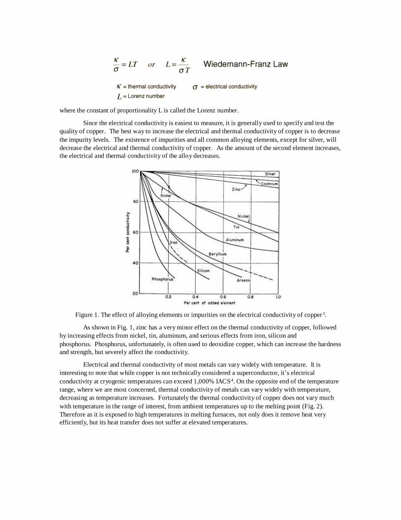
Figure 1. The effect of alloying elements or impurities on the electrical conductivity of copper 3.
As shown in Fig. 1, zinc has a very minor effect on the thermal conductivity of copper, followed
by increasing effects from nickel, tin, aluminum, and serious effects from iron, silicon and
phosphorus. Phosphorus, unfortunately, is often used to deoxidize copper, which can increase the hardness
and strength, but severely affect the conductivity.
Electrical and thermal conductivity of most metals can vary widely with temperature. It is
interesting to note that while copper is not technically considered a superconductor, it’s electrical
conductivity at cryogenic temperatures can exceed 1,000% IACS4. On the opposite end of the temperature
range, where we are most concerned, thermal conductivity of metals can vary widely with temperature,
decreasing as temperature increases. Fortunately the thermal conductivity of copper does not vary much
with temperature in the range of interest, from ambient temperatures up to the melting point (Fig. 2).
Therefore as it is exposed to high temperatures in melting furnaces, not only does it remove heat very
efficiently, but its heat transfer does not suffer at elevated temperatures.
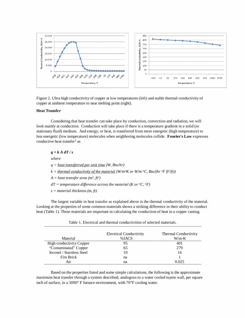
Figure 2. Ultra high conductivity of copper at low temperatures (left) and stable thermal conductivity of
copper at ambient temperature to near melting point (right).
Heat Transfer
Considering that heat transfer can take place by conduction, convection and radiation, we will
look mainly at conduction. Conduction will take place if there is a temperature gradient in a solid (or
stationary fluid) medium. And energy, or heat, is transferred from more energetic (high temperature) to
less energetic (low temperature) molecules when neighboring molecules collide. Fourier's Law expresses
conductive heat transfer5 as
q = k A dT / s
where
q = heat transferred per unit time (W, Btu/hr)
k = thermal conductivity of the material (W/moK or W/m oC, Btu/(hr oF ft2/ft))
A = heat transfer area (m2, ft2)
dT = temperature difference across the material (K or oC, oF)
s = material thickness (m, ft)
The largest variable in heat transfer as explained above is the thermal conductivity of the material.
Looking at the properties of some common materials shows a striking difference in their ability to conduct
heat (Table 1). These materials are important in calculating the conduction of heat in a copper casting.
Table 1. Electrical and thermal conductivities of selected materials.
Material
Electrical Conductivity
%IACS
Thermal Conductivity
W/m-K
High conductivity Copper
“Contaminated” Copper
Inconel / Stainless Steel
Fire Brick
Air
95
65
10
na
na
401
279
16
1
0.025
Based on the properties listed and some simple calculations, the following is the approximate
maximum heat transfer through a system described, analogous to a water cooled tuyere wall, per square
inch of surface, in a 3000° F furnace environment, with 70°F cooling water.

Table 2. Heat Transfer through a hypothetical copper tuyere wall
For the hard-surface weld overlays, there are a variety of materials used, mainly with
combinations of nickel and/or chrome for the primary purpose of abrasion resistance. All these weld
overlays reduce the conductivity of the system. When further considering the 3-dimensional heat transfer,
this reduction can result in tremendous lateral thermal differences which can lead to localized hot spots to
the point of melting. Some examples will be shown later of the consequences of these arrangements.
ABOUT CALORIZING
The calorizing process was developed by General Electric in the early 20th century, after an
extensive amount of research on ways to protect their heating elements. Mr. Emery Gilson of General
Electric was the first inventor to be awarded a patent for calorizing, “Process of Treating Metal”, on March
24, 19146. However another G. E. employee, Mr. Tycho Van Aller, actually filed his application 16
months earlier, “Treatment of Metals”, but it was not granted until October 5, 19157. The processes
described are almost identical, and cover both ferrous and non-ferrous metals. Both men were very active
with a variety of inventions, including carburetors, soldering irons, x-ray electrodes and lubrication of
bearings.
The General Electric engineers mentioned above researched two basic methods to protect metals.
One, to apply a coating to the surface, and the other, to modify the material itself. Calorizing is “the other”
process. Calorizing is a pack cementation process, and is also called aluminizing, alonizing, and more
recently, ceramalloying8. The calorizing treatment involves loading metal parts into a container, or retort,
and surrounding them with a blend of proprietary metal powders, including aluminum. The retort is then
hermetically sealed and placed in a furnace where it is heated to a specific temperature, and held for a
specified length of time. Chemical reactions create a transport mechanism by which aluminum is
introduced into the surface of the component. Regardless of the substrate material, i.e. ferrous or non-
ferrous, this produces an inter-metallic alloy layer that provides protection against high-temperature
corrosion, and erosive wear. In addition, under certain conditions, the process can be used to create an
outer growth layer of alumina to be present to provide a barrier to oxidation and also liquid metal
penetration. Calorized layer thickness is controlled by temperature, and time at temperature. After furnace
cooling, the retort is opened and the parts removed and cleaned of excess powder. Secondary operations
such as straightening, trimming, fabrication, etc. can then be performed as required. There are many
benefits of this technology. The intermetallic alloy layer formed is not a coating; due to the establishment
of a metallurgical bond, the alloy layer cannot be chipped off. This protective layer can only be removed
through machining. And since diffusion is not a line-of-sight technology like thermal spray, the protective
layer can be created on the inside of pipes and on components with a complex shape that are difficult to
protect with conventional spray coating methods. The introduction of aluminum into the surface of a base
metal, seals the base metal. This does not allow oxygen and other gases to diffuse into the microstructure
and cause corrosion. In addition, the intermetallic layer can be much harder than the base metal, resulting
in improved wear resistance. The aluminum oxide on the surface is an extremely stable material and acts as
a ceramic barrier.
Heat Transfer,
BTU/hr
Material comprising Tuyere Wall
95,000
68,500
9,800
Pure copper, 95% IACS, 5/8” thick
Contaminated copper, 65% IACS, 5/8” thick
3/16” Inconel weld, on pure copper, 5/8” thick

When one researches calorizing applications, the main references are to treating ferrous parts,
mainly steel. The most common usage has been steel piping for chemical plants, and parts for other
corrosive environments such as cement and limestone processing, power generation plants, heat treating
furniture, seamless tube mills, metal forming plants and many more which use components made of
different ferrous alloys, including stainless steel. The calorized layer contains aluminum oxide that forms
at the surface during treatment or in service, and this oxide creates an extremely effective barrier to
oxidation, sulphidation, decarburization and carburization in medium and high temperature operating
environments. Samples of untreated steel pipe subjected oxidation testing at 1200 °C in air for 12 hours
showed heavy scale with weight gain of 31.6%, while calorized pipe remained unaffected, with a weight
gain of 0.07%. Similar results were recorded in the same report referenced for corrosion tests in nitric
acid9.
Figure 3. Samples of calorized, uncalorized, and control pipe (steel) subjected to oxidation testing.
With aluminum oxide at the surface, and a diffused intermetallic aluminide layer formed beneath
it, calorized parts have higher hardness than the substrate, and provides increased abrasion resistance.
Testing results in the same report, above, have shown this to increase the surface hardness by up to five
times. .
Figure 4. Vickers hardness testing on calorized steel pipe (left), and pipe microstructure (right).
Most of the development and resulting applications for calorizing since the early 1900’s have
been with steel. However in the late1970’s Bethlehem Steel was investigating the use of coatings on their
blast furnace tuyeres, and ran some trials of calorized copper tuyeres, cast at their copper foundry in
Bethlehem, PA with calorizing done by Alon Processing of Tarentum, PA. The tuyeres were installed at
one of the blast furnaces at their Lackawanna, NY plant. At that time, the results were not conclusive due
to the small nature of the trial. In the 1980’s, Bethlehem Steel carried out further work to improve blast
furnace tuyere life involving ceramic coatings applied by flame spray and plasma spray. Testing was done
at Bethlehem’s Sparrows Point L blast furnace, but the coatings were not robust enough to consistently
survive the blast furnace environment.
In the late 1990’s, Bethlehem Steel decided to again look at calorizing copper, and began testing
samples at their Homer Research Labs, in Bethlehem, PA. Based on initial positive results, they
recommended plant trials at C and D blast furnaces in Burns Harbor, IN. Some of these laboratory results
will be discussed later. Following testing and plant trials recommended by engineers at Homer Research
Labs, Burns Harbor, has been successfully using calorized copper in the blast furnace for the past 15 years
with excellent results. The success of calorized copper in the blast furnace has brought opportunities in
other areas, such as cupola tuyeres, BOF lance tips, EAF burners and cooling panels, and smelting furnace
panels.
IMPROVING PERFORMANCE
The reason copper is used at all in water-cooled castings is its excellent thermal conductivity; but
along with that property comes the low melting point. Therefore it is important to achieving optimal
cooling to withstand high heat flux conditions and avoid burnout by molten metal or slag. Modeling water
flow is one way to study how proper design can result in optimal water flow and cooling to avoid burnout.
Modeling
Excellent work has been done over the years to predict, simulate and test the burnout of copper
components, mainly tuyeres10,11,12 . An optimum water velocity of 15 m/s has been found in lab testing to
be the aim to reduce copper burn-through. This number is fine, in theory, if the water flow is uniform
across the water passage. But more often than not, due to complex casting designs, the water flow is not
uniform. The presence of baffles and sharp corners in the water jacket creates streams of higher velocity
along with eddy currents, back-flow and recirculation zones. In the 1970’s, Bethlehem Steel performed
water modeling using actual copper castings, with outer walls machined away, and replaced with Plexiglas
windows. A bead injection apparatus was built to introduce plastic beads of differing specific gravities
into the water stream, to more clearly show water flow. Alterations were made to the internal configuration
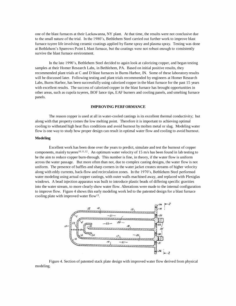
to improve flow. Figure 4 shows this early modeling work led to the patented design for a blast furnace
cooling plate with improved water flow13.
Figure 4. Section of patented stack plate design with improved water flow derived from physical
modeling.

For copper tuyeres, the same model construction was used, albeit slightly more difficult due to the tuyere
configuration. In the same manner as the stack plate, poor water flow was easily detected and
modifications could be made to the tuyere water jackets to reduce stagnant areas. Some of these stagnant
areas essentially had water velocity of zero. The heat transfer here being very low can result in the creation
of “hot spots” which could lead to burnouts. With the advent of computational fluid dynamics packages
for the computer and solid modeling, the same designs could be investigated and confirmed on a computer.
Figure 5 shows a copper blast furnace tuyere solid model and water flow lines using CFD14.
Figure 5. Blast furnace tuyere solid model (left) and CFD 3-D cooling water velocity, scale in m/s.
Coatings
The use of coatings can also protect surfaces from molten metal as well as improve wear
resistance. Again, much work has been done in the area of coatings for copper blast furnace components,
and more recently for Basic Oxygen Furnace (BOF) oxygen lance tips. U. S. Steel Research &
Technology Center conducted hot metal splash tests on copper samples with and without an array of
coatings15. Previous work performed at Bethlehem Steel has shown similar results16. Several conclusions
were made from this work. First, it was very easy to simulate a tuyere burn with hot metal in the lab. The
resulting burns appeared very similar to actual failed tuyeres. Second, ceramic coatings of alumina and
zirconia were very effective in preventing burns in the lab. In the field, however they are easily abraded
from the casting surfaces, and can even be seriously damaged before getting into the furnace, by normal
handling in storage and at tuyere change. Abrasion testing in the lab proves this out, and their longevity in
the furnace was questioned17. To prevent abrasion, weld overlays have been used, and more recently
calorizing. Testing of weld overlays or Inconel coatings has shown mixed results in hot metal splash
testing. Molten iron can easily alloy with most welds and penetration can eventually occur. A more
compelling case can be made for calorizing.
As discussed, this is a diffusion treatment resulting in a far more durable layer which extends into
the copper18. It has shown two main benefits. First it is up to six times harder than bare copper, which
means it is more abrasion resistant in service. Test results of average microhardness measurements from
five locations in both a calorized area and the copper substrate are shown19. More recent lab testing of
calorized samples has shown a uniform calorized layer approximately 1 mm thick, with three distinct
layers: an outermost layer comprised of alumina, a thick layer of intermetallic phases, and a thin Cu-Al
inter-diffusion layer. According to Behnood, “The bond between the coating layer and the substrate
appeared to be continuous with no void or gap”20.
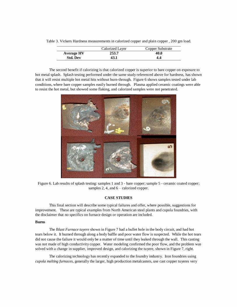
Table 3. Vickers Hardness measurements in calorized copper and plain copper , 200 gm load.
Calorized Layer Copper Substrate
Average HV
Std. Dev
253.7
43.1
40.0
4.4
The second benefit if calorizing is that calorized copper is superior to bare copper on exposure to
hot metal splash. Splash testing performed under the same study referenced above for hardness, has shown
that it will resist multiple hot metal hits without burn-through. Figure 6 shows samples tested under lab
conditions, where bare copper samples easily burned through. Plasma applied ceramic coatings were able
to resist the hot metal, but showed some flaking, and calorized samples were not penetrated.
Figure 6. Lab results of splash testing: samples 1 and 3 - bare copper; sample 5 - ceramic coated copper;
samples 2, 4, and 6 – calorized copper.
CASE STUDIES
This final section will describe some typical failures and offer, where possible, suggestions for
improvement. These are typical examples from North American steel plants and cupola foundries, with
the disclaimer that no specifics on furnace design or operation are included.
Burns
The Blast Furnace tuyere shown in Figure 7 had a bullet hole in the body circuit, and had hot
tears below it. It burned through along a body baffle and poor water flow is suspected. While the hot tears
did not cause the failure it would only be a matter of time until they leaked through the wall. This casting
was not made of high conductivity copper. Water modeling confirmed the poor flow, and the problem was
solved with a change in supplier, improved design, and calorizing the tuyere, shown in Figure 7, right.
The calorizing technology has recently expanded to the foundry industry. Iron foundries using
cupola melting furnaces, generally the larger, high production metalcasters, use cast copper tuyeres very
similar to those used in the blast furnace, and have similar issues with molten iron splash. Recent trials
using calorized tuyeres in the cupola have shown improved life, Figure 8. .
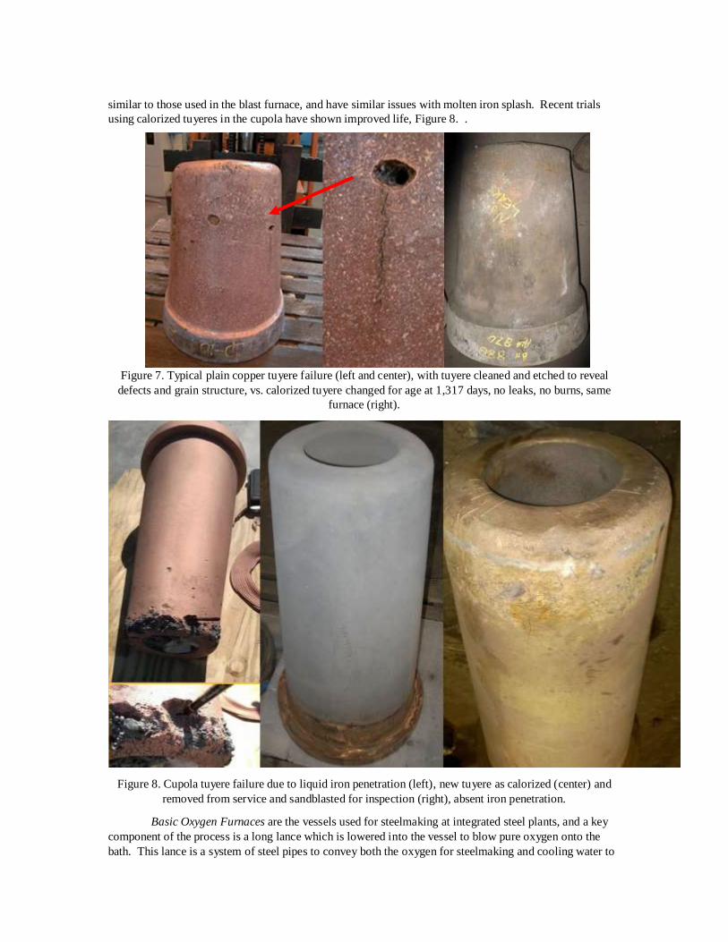
Figure 7. Typical plain copper tuyere failure (left and center), with tuyere cleaned and etched to reveal
defects and grain structure, vs. calorized tuyere changed for age at 1,317 days, no leaks, no burns, same
furnace (right).
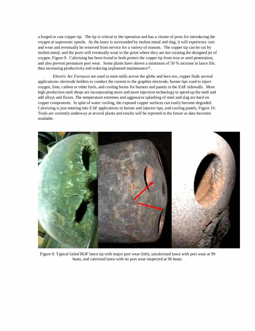
Figure 8. Cupola tuyere failure due to liquid iron penetration (left), new tuyere as calorized (center) and
removed from service and sandblasted for inspection (right), absent iron penetration.
Basic Oxygen Furnaces are the vessels used for steelmaking at integrated steel plants, and a key
component of the process is a long lance which is lowered into the vessel to blow pure oxygen onto the
bath. This lance is a system of steel pipes to convey both the oxygen for steelmaking and cooling water to
a forged or cast copper tip. The tip is critical to the operation and has a cluster of ports for introducing the
oxygen at supersonic speeds. As the lance is surrounded by molten metal and slag, it will experience cuts
and wear and eventually be removed from service for a variety of reasons. The copper tip can be cut by
molten metal, and the ports will eventually wear to the point where they are not creating the designed jet of
oxygen, Figure 9. Calorizing has been found to both protect the copper tip from iron or steel penetration,
and also prevent premature port wear. Some plants have shown a minimum of 50 % increase in lance life,
thus increasing productivity and reducing unplanned maintenance21.
Electric Arc Furnaces are used in mini-mills across the globe and here too, copper finds several
applications: electrode holders to conduct the current to the graphite electrode, burner tips used to inject
oxygen, lime, carbon or other fuels, and cooling boxes for burners and panels in the EAF sidewalls. Most
high production melt shops are incorporating more and more injection technology to speed up the melt and
add alloys and fluxes. The temperature extremes and aggressive splashing of steel and slag are hard on
copper components. In spite of water cooling, the exposed copper surfaces can easily become degraded.
Calorizing is just entering into EAF applications in burner and injector tips, and cooling panels, Figure 10.
Trials are currently underway at several plants and results will be reported in the future as data becomes
available.
Figure 9. Typical failed BOF lance tip with major port wear (left), uncalorized lance with port wear at 99
heats, and calorized lance with no port wear inspected at 96 heats.

Figure 10. Calorized copper EAF castings. Burner (left) and burner panel (center & right) currently
undergoing trials.
Wear and Abrasion
The two tuyeres shown in Figure 11 were produced by the same foundry from high conductivity
copper. They came from the same blast furnace, in close proximity to each other, and installed roughly at
the same time. The uncalorized tuyere failed after 685 days due to a bullet hole, and also had excessive
abrasion to the body, almost through the wall. After following plain copper tuyere performance for some
time, it was found that the rate of abrasion was approximately 1/32” per month, and quite repeatable. The
calorized tuyere pictured was in the furnace for over 2 years (774 days) and did not fail, but was pulled to
change a leaking tuyere cooler. The abrasion seen on the plain copper tuyere is not present on the
calorized tuyere. This is typical of calorized high conductivity copper tuyere performance in a high-
production blast furnace operations. Recent record life has been recorded in excess of 1,300 days.
Figure 11. Worn, failed tuyere (left) bare copper 685 days, calorized tuyere (right), 774 days.
Hard Surface Welding
The two dual-chambered tuyeres pictured in Figure 12 both failed through the hard surface welds
applied to prevent abrasive wear. The coatings are different, on the left is an iron-chrome based overlay
and on the right, a nickel-based alloy, but they both failed. And in both cases the hard surface area is
peppered with hits of hot metal. The weld materials will in most cases easily alloy with hot metal, causing
penetration into the copper.
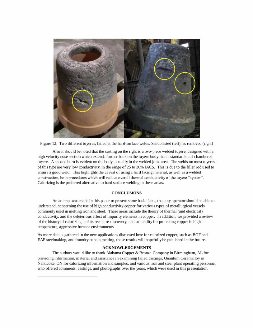
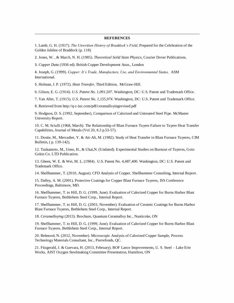
Figure 12. Two different tuyeres, failed at the hard-surface welds. Sandblasted (left), as removed (right)
Also it should be noted that the casting on the right is a two-piece welded tuyere, designed with a
high velocity nose section which extends further back on the tuyere body than a standard dual-chambered
tuyere. A second burn is evident on the body, actually in the welded joint area. The welds on most tuyeres
of this type are very low conductivity, in the range of 25 to 30% IACS. This is due to the filler rod used to
ensure a good weld. This highlights the caveat of using a hard facing material, as well as a welded
construction, both procedures which will reduce overall thermal conductivity of the tuyere “system”.
Calorizing is the preferred alternative to hard surface welding in these areas.
CONCLUSIONS
An attempt was made in this paper to present some basic facts, that any operator should be able to
understand, concerning the use of high conductivity copper for various types of metallurgical vessels
commonly used in melting iron and steel. These areas include the theory of thermal (and electrical)
conductivity, and the deleterious effect of impurity elements in copper. In addition, we provided a review
of the history of calorizing and its recent re-discovery, and suitability for protecting copper in high-
temperature, aggressive furnace environments.
As more data is gathered in the new applications discussed here for calorized copper, such as BOF and
EAF steelmaking, and foundry cupola melting, those results will hopefully be published in the future.
ACKNOWLEDGEMENTS
The authors would like to thank Alabama Copper & Bronze Company in Birmingham, AL for
providing information, material and assistance in examining failed castings, Quantum Ceramalloy in
Nanticoke, ON for calorizing information and samples, and various iron and steel plant operating personnel
who offered comments, castings, and photographs over the years, which were used in this presentation.
REFERENCES
1. Lamb, G. H. (1917). The Unwritten History of Braddock’s Field, Prepared for the Celebration of the
Golden Jubilee of Braddock (p. 118)
2. Jones, W. , & March, N. H. (1985). Theoretical Solid State Physics, Courier Dover Publications.
3. Copper Data (1936 ed). British Copper Development Assn., London
4. Joseph, G. (1999). Copper: It’s Trade, Manufacture, Use, and Environmental Status, ASM
International.
5. Holman, J. P. (1972). Heat Transfer, Third Edition, McGraw-Hill.
6. Gilson, E. G. (1914). U.S. Patent No. 1,091,507. Washington, DC: U.S. Patent and Trademark Office.
7. Van Aller, T. (1915). U.S. Patent No. 1,155,974. Washington, DC: U.S. Patent and Trademark Office.
8. Retrieved from http://q-c-inc.com/pdf/ceramalloyingrevised.pdf
9. Hodgson, D. S. (1992, September), Comparison of Calorized and Untreated Steel Pipe. McMaster
University Report.
10. C. M. Sciulli (1968, March). The Relationship of Blast Furnace Tuyere Failure to Tuyere Heat Transfer
Capabilities, Journal of Metals (Vol 20, #,3 p.53-57).
11. Dostie, M., Mercadier, Y. & Ait-Ali, M. (1982). Study of Heat Transfer in Blast Furnace Tuyeres, CIM
Bulletin, ( p. 139-142).
12. Tsukamoto, M., Ueno, H., & Ukai,N. (Undated). Experimental Studies on Burnout of Tuyeres, Goto
Gokin Co. LTD Publication.
13. Gheen, W. E. & Wei, M. L. (1984). U.S. Patent No. 4,487,400. Washington, DC: U.S. Patent and
Trademark Office.
14. Shellhammer, T. (2010, August). CFD Analysis of Copper, Shellhammer Consulting, Internal Report.
15. Dalley, A. M. (2001). Protective Coatings for Copper Blast Furnace Tuyeres, ISS Conference
Proceedings, Baltimore, MD.
16. Shellhammer, T. to Hill, D. G. (1999, June). Evaluation of Calorized Copper for Burns Harbor Blast
Furnace Tuyeres, Bethlehem Steel Corp., Internal Report.
17. Shellhammer, T. to Hill, D. G. (2003, November). Evaluation of Ceramic Coatings for Burns Harbor
Blast Furnace Tuyeres, Bethlehem Steel Corp., Internal Report.
18. Ceramalloying (2013). Brochure, Quantum Ceramalloy Inc., Nanticoke, ON
19. Shellhammer, T. to Hill, D. G. (1999, June). Evaluation of Calorized Copper for Burns Harbor Blast
Furnace Tuyeres, Bethlehem Steel Corp., Internal Report.
20. Behnood, N. (2012, November). Microscopic Analysis of Calorized Copper Sample, Process
Technology Materials Consultant, Inc., Pierrefonds, QC.
21. Fitzgerald, J. & Guevara, H. (2013, February). BOF Lance Improvements, U. S. Steel – Lake Erie
Works, AIST Oxygen Steelmaking Committee Presentation, Hamilton, ON