Embed Size (px)
Citation preview

-1-
California Test 301 STATE OF CALIFORNIA—BUSINESS, TRANSPORTATION AND HOUSING AGENCY March 2000
DEPARTMENT OF TRANSPORTATION ENGINEERING SERVICE CENTER Transportation Laboratory 5900 Folsom Blvd. Sacramento, California 95819-4612
METHOD FOR DETERMINING THE RESISTANCE “R” VALUE OF TREATED AND UNTREATED BASES, SUBBASES, AND
BASEMENT SOILS BY THE STABILOMETER
CAUTION: Prior to handling test materials, performing equipment setups, and/or conducting this
method, testers are required to read “SAFETY AND HEALTH” on Page 3, Section D of this method. It is the responsibility of the user of this method to consult and use appropriate safety and health practices and determine the applicability of regulatory limitations before any testing is performed.
A. OVERVIEW
This method covers the procedure for determining the Resistance (R-value) of both treated and untreated soils or aggregates. This test method is divided into the following parts:
1. Preparation of Materials for Testing. 2. Compaction, Exudation Pressure
Determination, and Measurements of R-Value Test Specimens.
3. Determining the Expansion Pressure of
R-Value Test Specimens. 4. Measuring the Horizontal Pressure and
Displacement By Means of the Stabilometer.
5. Calculating the Moisture Content and
Density of R-Value Test Specimens. 6. Determining the R-Value of a Material. 7. Reporting Results.
B. APPARATUS
1. Riffle splitters, as prescribed in California Test 201.
2. Scales, 5000 g capacity, accurate to 1 g. 3. Scales, 500 g capacity, accurate to 0.1 g. 4. Turntable capable of holding mixing pan. 5. Water spray metering device (calibrated
to the nearest milliliter.) 6. Mixing pan approximately 300 mm
diameter and approximately 100 mm deep with sides curving in at the bottom. The radius of side curvature should be approximately equal to the pan depth.
7. Large mixing spoon approximately
60 mm wide or triangular hand trowel about 125 mm in length.
8. Expansion pressure devices (Figures 1
and 2) for each specimen and one for measuring compacted specimen height.
9. A deflection gage (expansion pressure
dial) having graduations or increments to 0.002 mm and a range of 5 mm (Figure 2).

California Test 301 March 2000
- 2 -
10. A 4-mm Allen wrench (Figure 2). 11. Height calibration gage. A metal cylinder
or block between 50 and 75 mm in height, measured to a tolerance of 0.1 mm with sufficient top and bottom surface to support a perforated disc and stem without tipping.
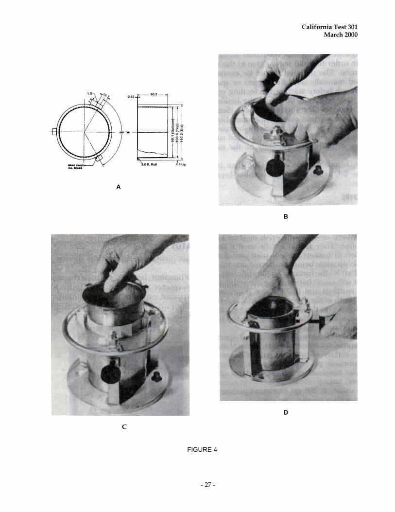
12. Mold, 101.6 ± 0.13 mm inside diameter by
127 ± 0.2 mm high fabricated to an inside surface roughness of 250 microfinish, General Electric roughness scale. (See note, Figure 3.) Discard any used mold that becomes elliptical in excess of 101.6 ± 0.25 mm or loses the surface texture to the extent that it has an almost “mirror like” finish.
13. Mold Holder (Figure 4) designed to
firmly restrain a mold on the compactor turntable during compaction. The base of the mold holder shall have a metal plate 100.8 0.5 mm in diameter and 13 0.5 mm high. The plate shall be an integral part of the base of the mold holder. A rubber disc (Apparatus #16) shall be cemented to the plate.
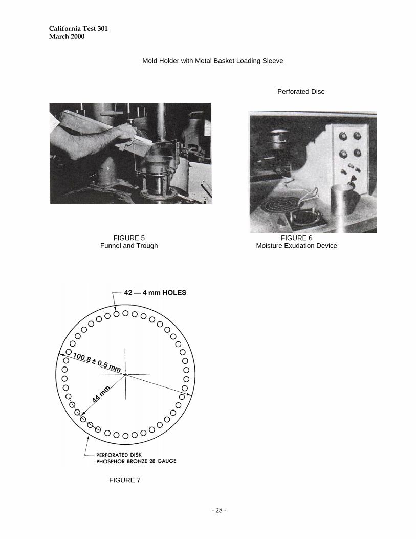
14. Funnel which fits over the mold to
prevent spillage during feeding and compaction (Figure 5).
15. A compactor, conforming to the
requirements of California Test 101 or California Test 104, capable of applying an average contact pressure of 2410 ± 110 kPa to the tamper foot with provisions for maintaining this pressure during changes in sample height. The load-time trace shall be free of “chatter” or evidence of impact-associated changes in slope. The rise time for application of foot pressure, in the range from 240 to 2070 kPa, shall not be less than 0.07 nor more than 0.20 s.
The dwell time, measured at 2070 kPa foot pressure, shall not be less than 0.15 nor more than 0.45 s. The pressure
release or removal time shall not be greater than 0.60 s.
The compactor shall apply the load at the
rate of 30 tamps per min at 2410 kPa. The compactor shall include a counter for measuring the number of tamps applied to a specimen and a trough (Figure 5) for mechanically or manually feeding the sample into the mold in 20 increments. The tamper foot shall have a surface area of 2.6 10-3 m2 and conform to the dimensions shown in California Test 101.
16. Rubber discs 100 1 mm in diameter by
3 0.5 mm thick and having a durometer hardness of 80 ± 5, Garlock 22 or equivalent.
17. Metal rod, 40 to 50 mm in diameter, flat
ended. 18. Moisture exudation indicating device
consisting of a detection plate and display panel (Figure 6) and conforming to the dimensions and tolerances on Transportation Laboratory Plan D-534. The detection plate is wired to the display panel where lights are activated as moisture contacts the respective contact points. Some plates include a contact ring that detects free water being squeezed from under the edge of the mold. Some units have the contacts wired directly to the testing machine to automatically record the applied pressure when exudation occurs. Battery powered units are independent of the testing machine and serve only to provide a visual reference to enable the operator to read and record the exudation pressure manually. This unit does not include a contact ring so the operator must keep a constant watch for free water at the edge of the mold.
19. Disc, 0.4 mm thick, phosphor bronze,
with perforations, 100.8 0.5 mm diameter (Figure 7). Several are needed. At least one is needed for exudating
California Test 301 March 2000
- 3 -
cohesive materials and one for each basket used for Class 2 aggregate base or other cohesionless materials.
20. Specimen follower, solid wall, 100.33
± 0.13 mm outside diameter by 130 ± 6 mm long, 4 kg maximum (Figure 6).
21. A 45 kN minimum capacity compression
testing machine (CTM) with a spherically seated and free acting upper head conforming to the requirements of California Test 108. The machine must accommodate shims to lock the head in a horizontal plane or an additional 45 kN capacity CTM having the upper head firmly fixed in horizontal plane will be required.
22. Basket making device consisting of a
98 ± 2 mm diameter cylindrical form and a 12.7-mm masking tape dispenser (Figure 9-A).
23. Metal basket loading sleeve constructed
of #304 stainless steel, 0.6 mm thick (Figure 4-A).
24. Drip pans approximately 150 mm
diameter and 50 mm deep for use under expansion pressure devices.
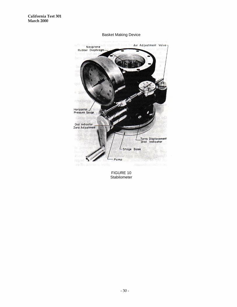
25. Stabilometer and accessories (Figure 10). 26. Standard metal specimen, 101.6
± 0.13 mm outside diameter by 165 mm long.
C. MATERIALS
1. Cardboard discs, 100 mm outside diameter cut from approximately 70 kg manila stock (Office of Purchasing and Warehousing (OPW) No. 6640-0130-8).
2. Filter paper, 100 mm diameter and
0.15 mm thick, smooth surface, medium filtering speed, medium retention. VWR grade 413 and Ahlstrom grade 613 filters meet this criterion.
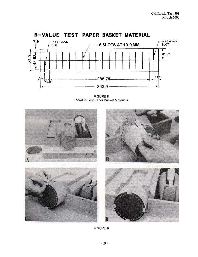
3. Strips of slotted paper, for making baskets, composed of 27 kg brown Kraft paper, 64 mm wide by 339 mm long with slots (Figure 8) (OPW No. 6640-0250-2).
4. Masking tape 12.7 mm wide. 5. Filter paper, 110 mm diameter by
0.15 mm thick, creped surface, medium-fast filtering speed, medium retention. S&S Sharkskin general purpose filter paper meets this criteria (OPW No. 6640-0160-1).
D. SAFETY AND HEALTH
Soils and aggregates may contain bacterial, organic and/or chemical contaminants that can be harmful to one's health. The wearing of MSHA/NIOSH approved dust masks and protective gloves when handling material is advised. Observe good hygiene practices. Wash hands after handling samples and before eating, drinking or smoking. Dust, noise, lifting and operation of equipment are encountered in the procedures in this test method. It is not possible to completely eliminate these risks, but steps should be taken to minimize them as much as possible. The use of dust palliatives on workroom floors and dust collection units are very effective methods of reducing dust conditions. Enclosures built around noisy equipment can eliminate much of the noise. The use of sound deadening material should be utilized when appropriate. The use of ear plugs or ear muffs is recommended when other noise suppression measures are inappropriate. Guards or shields must be provided around exposed moving parts of machinery. Personnel should be instructed in the proper operation of each machine and in proper
California Test 301 March 2000
- 4 -
lifting methods. The use of table-high carts to move heavy items can minimize the lifting. Caution must be exercised in the operation of the compactor so as not to allow any object other than the sample itself to intercede between the compactor foot and the mold at any time while the ram is in motion. The clearance between the inside edge of the mold and the compactor foot is approximately 1.5 mm. The applied shearing force of 4900 N could cause severe injury to an operator's hand if caught between the compactor foot and the mold. A clear plastic guard has been designed for the California compactor to be used as an aid in safeguarding against this hazard. When picking up both the stabilometer and stage base together, make sure that the lock shoe on the bottom of the stabilometer shell is in position to prevent the base from slipping out. The stage weighs about 9 kg and could cause serious injury if it fell on the operator's foot. It is good practice when carrying the entire assembly to grip it by the bronze adjusting nut on the stage base. Prior to handling materials, testing, or disposing of any waste materials, testers are required to read Caltrans Laboratory Safety Manual: Part A, Section 5.0, Hazards and Employee Exposure; Part B, Sections: 5.0, Safe Laboratory Practices; 6.0, Chemical Procurement Distribution and Storage; and 10.0, Personal Protective Apparel and Equipment; and Part C, Section 1.0, Safe Laboratory Practices.
PART 1. PREPARATION OF MATERIALS FOR
TESTING A. Sample Preparation
1. Untreated Soils and Aggregates
a. Process samples as prescribed in California Test 201.
The preparation of R-value test
samples must include removal of
coatings from coarse aggregates, and clay lumps must be broken down to pass the 4.75-mm sieve. This is important because relatively small test specimens are used. Therefore, it is necessary that the test specimen be prepared very accurately. (Note: Moisture reduction may be necessary for proper sample preparation. Do not completely dry the sample. Moisture reduction shall be limited to the amount necessary to permit a complete separation on the 4.75-mm sieve and to develop a free-flowing condition in the portion passing the 4.75-mm sieve. Moisture reduction may be performed by any means that does not heat the sample in excess of 60°C).
b. Miscellaneous lumps of bituminous
mix or other friable particles need to be crumbled or pulverized to their minimum durable size on all sieves through the 4.75-mm sieve.
c. Vegetation and other deleterious
substances are a part of the sample and should not be removed.
d. Note the presence of bituminous
lumps or deleterious substances in the sample on the test report and whether any of these materials compromise a portion of the R-value test specimens.
e. Follow the sieving instructions in
California Test 202 to separate the coarse portions into individual coarse size fractions. Keep the size fractions separated for batching.
2. Reclaimed Asphalt Concrete and
Portland Cement Concrete, Previously Treated Materials, and Glass.
a. Samples of these materials generally
contain large chunks or particles that normally require further processing for use in roadbed construction.
California Test 301 March 2000
- 5 -
b. Reduce these materials to a size
applicable to construction processes. This reduction is usually best accomplished by crushing.
c. Process the reduced material in the
same manner as untreated soils and aggregates.
3. Field Samples Containing Recycled
Materials
a. Process the samples in the same manner as untreated soil and aggregates in Section A-1.
b. The presence of recycled material
compromising a portion of any oversize material should be noted in the test report.
B. Calculation of Batch Mass
1. Untreated Soils, Aggregates, Recycled Materials, and Samples Containing Recycled Materials.
a. Determine the "as received" grading
of the sample as prescribed in California Test 202. The "as received" grading is the grading as measured on a sample prior to any adjustment such as scalping, wasting or crushing of oversize material. Recycled material, which has been reduced in size, is considered an "as received" grading.
b. Establish the "as used" grading as
prescribed in California Test 105. In cases where 100 % of the material as received passes the 19.0-mm sieve and no adjustments are necessary, the "as received" and the "as used" gradings will be the same.
Rejection of oversize material
(scalping) shall conform to the following criteria:
(1) If 75 % or more of the sample as received passes the 19.0-mm sieve, scalp the sample on the 19-mm sieve
(2) If less than 75 % of the sample as
received passes the 19.0-mm sieve, scalp the sample on the 25.0-mm sieve.
c. Calculate batch mass for the desired
test specimen, which will be proportional to the sample gradation.
(1) 1200 g samples are normally
required; however, a lesser amount may be used for lightweight materials when it is certain that the lesser mass will provide a 63.5 ± 1.3 mm high specimen.
(2) The "cumulative mass" method is
the preferable method of combining the various size components of materials for the R-value test.
(3) The following are examples of
computations for batching by the "cumulative mass" method:
(a) Single sample with the
following grading:
Sieve Passing
As Received Percent Passing
As Used Percent
25.0 mm 100 100 19.0 mm 96 100 12.5 mm 91 95
9.5 mm 85 89 4.75 mm 71 74
Since more than 75 % of the as received sample passes the 19.0-mm sieve, the sample must be scalped on the 19.0-mm sieve and the as used grading determined as prescribed in California Test 105. Calculate the cumulative mass based on the as received grading for a 1200 g sample as follows:
California Test 301 March 2000
- 6 -
Size Cumulative
Percent Retained Cumulative
Mass (grams) 19.0 to 12.5 mm (96-91) = 5 (5/96) x 1200=63
19.0 to 9.5 mm (96-85) = 11 (11/96) x 1200=138 19.0 to 4.75 mm (96-71) = 25 (25/96) x 1200=313
Passing 4.75 mm (96-0) = 96 (96/96) x 1200=1200
(b) Two samples having the gradings and combination as shown:
Aggregate Gradation, Percent Passing
As Received Sample Proportional 80% 20%
Size, mm No. 1 No. 2 No. 1 No. 2 Combined
25.0 100 80 20 100 19.0 90 72 20 92 12.5 85 100 68 20 88 9.5 80 95 64 19 83 4.75 70 90 56 18 74
Since more than 75 % of the combined materials pass the 19.0-mm sieve the sample must be scalped on the 19.0-mm sieve and the as used grading determined as prescribed in California Test 105.
Aggregate Gradation, Percent Passing
Size
Combined As Used
(Scalp 19 mm) 25.0 mm 100 100 19.0 mm 92 100 12.5 mm 88 96
9.5 mm 83 90 4.75 mm 74 80
Calculate the percent of each size for the proportioned and combined gradings for each size as shown:
Percent of Each Size
Proportioned Grading
Size
No. 1
No. 2 Combined
No. 1 & No. 2 19.0 to 12.5mm 72-68 = 4 20-20 = 0 4+0 = 4 12.5 to 9.5mm 68-64 = 4 20-19 = 1 4+1 = 5 9.5 to 4.75mm 64-56 = 8 19-18 = 1 8+1 = 9
Passing 4.75mm 56 18 56+18 = 74
Calculate the cumulative mass for a 1200 g sample as shown:
Cumulative, Percent
Size
Combined No. 1 & 2
(%)
Add Sample
No. 1 (%)
Add Sample
No. 2 (%)
Combined No. 1 & 2
(%) 19.0 to 12.5 mm — 4 + 0 = 4 19.0 to 9.5 mm 4 + 4 = 8 + 1 = 9
19.0 to 4.75 mm 9 + 8 = 17 + 1 = 18 Passing 4.75 mm 18 + 56 = 74 + 18 = 92
Cumulative, Mass Size Add Sample
No. 1 g Add Sample
No. 2 g 19.0 to 12.5 mm 1200/92 x 4 = 52 1200/92 x 4 = 52
19.0 to 9.5 mm 1200/92 x 8 = 104 1200/92 x 9 = 117 19.0 to 4.75 mm 1200/92 x 17 = 222 1200/92 x 18 = 235 Passing 4.75 mm 1200/92 x 74 = 965 1200/92 x 92 = 1200
The percentage of material passing each sieve size, for the calculated combined mass, determined as prescribed in California Test 202, agrees with the as used percent passing previously calculated by California Test 105.
d. The illustrated calculations for
batching by the cumulative mass method are intended as a guide in determining the required mass. The cumulative mass method eliminates the need to remove each size fraction from the scale during the weighing process. It also reduces the tendency for mass discrepancies between specimens. Batching by weighing the individual size fractions is permissible. However, when batching by this method the size fractions should be combined and the actual mass for each specimen recorded.
2. Cement Treating of Untreated Materials
in the Laboratory:
a. Calculate the batch mass in the same manner as described for untreated soils, aggregates, recycled materials, and samples containing recycled materials (subsection 1 of this section).
b. The addition of cement is explained
in Section D, Curing of Specimens.
C. Batching of Specimens
The term "batching" when used in this procedure refers to the act of combining, according to previously calculated
California Test 301 March 2000
- 7 -
proportions, sufficient material in individual samples to fabricate R-value test specimens. Prepare sufficient specimens for testing. Normally, five test specimens are required (one for moisture content, one to establish specimen height, and three for R-value determination). Critical materials may require additional R-value tests. The exact number of tests is a matter of judgment dependent on the characteristics of the soil and tester skill.
1. Untreated Soils, Aggregates, Recycled
Materials, and Samples Containing Recycled Materials and Cement Treated Materials in the laboratory.
a. Using a riffle-type splitter separate
the passing 4.75 mm portion of the sample into approximate amounts needed for each specimen. By using a proper size splitter (10 to 8 mm openings) and careful procedures, it is possible to obtain amounts that are within 1 % of the desired mass.
b. Weigh the calculated amounts of the
retained 4.75 mm size fractions to the nearest gram.
c. Weigh (to the nearest gram) the
previously split passing 4.75 mm portion. Since the split portions may vary slightly in mass from the amount required, add or remove material to obtain the exact specimen mass.
(1) If the size fractions were weighed
separately, recombine them and record the total mass.
(2) When batching by the
"cumulative mass" method, each specimen will have the same total mass.
d. As each specimen is proportioned,
immediately place it in a moisture proof container with a tight fitting lid.
2. Determination of Initial Moisture Content
of R-Value Test Specimens
a. Utilize one of the prepared specimens for the determination of initial moisture content according to California Test 226. The moisture content shall be calculated to the nearest 0.1 %.
b. The moisture content of this specimen
shall be used as the initial moisture content for the remaining specimens.
D. Curing of Specimens
1. Untreated Soils, Aggregates, Recycled Materials, and Samples Containing Recycled Materials
a. Transfer a batched specimen from its
container to the mixing pan (Apparatus, #6).
b. Place the pan on the turntable
(Apparatus, #4). c. Using the water spray device
(Apparatus, #5) and trowel or mixing spoon (Apparatus, #7), mix the specimen and water.
d. Add approximately 1/2 to 2/3 of the
moisture necessary to obtain the saturation (Part 2, Section B-4). While mixing continuously rotate the pan horizontally beneath the water spray. Continue mixing for one minute after all the water has been added.
NOTE: The amount of water to be
added to a material is established by experience. With the exception of soils containing a high percentage of clay, generally, sufficient water has been added if the material no longer appears to be free flowing and tends to cling together when tightly squeezed in the hand, leaving only a slight trace or sensation of moisture
California Test 301 March 2000
- 8 -
on the skin. The presence of clay will often cause a material to cling together before 1/2 the moisture is added.
e. Record the amount of water added.
This addition of water is referred to as the "SOAK WATER".
f. Transfer all of the material (including
particles adhering to the pan and mixing tools) loosely into its container and replace the lid tightly on the container.
g. Allow the specimens to cure a
minimum of 16 h before compacting. h. The soak water addition and curing is
optional for aggregate bases meeting the Standard Specification grading requirements for Class 2 aggregate base.
i. Soak and cure the remaining sample
specimens as previously described.
2. Cement Treatment of Materials in the Laboratory.
a. Calculate the amount of cement to be
added to each specimen by the following formula:
Mc = C Ms/(100 + M1)
where:
Mc = mass of cement to the nearest 0.1 g
C = % of cement
Ms = specimen mass to the nearest g M1 = initial moisture content as
determined in Section C-2.
b. Weigh the amount of cement required for each test specimen.
c. Transfer a batched specimen of the
untreated material from its container to the mixing pan (Apparatus, #6).
d. Place the pan on the turntable
(Apparatus, #4). e. Add the previously weighed mass of
cement to the specimen and thoroughly mix with the material before adding any soak water.
f. Add soak water as described for
untreated soils, aggregates, recycled materials, and samples containing recycled materials in Section D, subsection 1, c through f.
g. Allow the specimens to cure a
minimum of 16 h (but not over 24 h) before compacting and exudating.
h. Soak and cure the remaining
specimens as described above.
PART 2. COMPACTION, EXUDATION PRESSURE DETERMINATION, AND MEASUREMENTS OF R-VALUE TEST SPECIMENS
The R-value of a material is determined when the material is in a state of saturation such that water will be exuded from the compacted test specimen when a 16.8 kN load (2.07 MPa) is applied. Since it is not always possible to prepare a test specimen that will exude water at the specified load, it is necessary to test a series of specimens prepared at different moisture contents. Four specimens are normally required. The first is used as a pilot to assist in determining the correct amount of material and the proper moisture content. (See Page 10, Section B 3, a, (2) for the formula.) The remainder will be used to establish the exudation pressure curve for the material. Normally, three specimens are enough to determine the R-value. However, in the case of critical materials, it is sometimes necessary
California Test 301 March 2000
- 9 -
to make additional tests in order that the true shape of the exudation pressure curve will be known at the "2.07 MPa" exudation point. The exact number of specimens to be fabricated is a matter of judgment but two specimens should exude water at or near 2.07 MPa. Specimens used in the R-value test should conform to the following criteria when possible.
Height = 63.5 ± 1.3 mm
Exudation pressure: One specimen should be above and two below 2.07 MPa, or two above and one below 2.07 MPa with a minimum spacing of 700 kPa between specimens. All samples should exude moisture when the pressure is between 700 and 5500 kPa, except when very high expansion pressures are expected. In the latter case, wetter specimens are sometimes necessary to get expansion pressures low enough to determine the R-value by expansion pressure. Two procedures are provided. The first (Section B) is to be used for soils and fine-grained aggregates which possess sufficient natural cohesiveness to maintain the specimens intact during the various test processes. The second procedure (Section C) is to be used for Class 2 aggregate bases or relatively cohesionless materials such as coarse, granular materials and clean sands that may crumble or lose integrity during the various test processes.
A. Apparatus Preparation
1. Calibration and operation of the compactor shall be in accordance with California Test 101 or California Test 104.
2. Adjustment of Expansion Pressure Device
(Apparatus, #8) for use in Specimen Height Measurement.
a. Clean off all dust and foreign material from the spring steel bar and adjustment plug.
b. Place the deflection gage (Apparatus,
#9) in position on the top bar of the expansion pressure device. The single bearing end must rest on the adjustment plug.
c. Use an Allen wrench (Apparatus,
#10) to raise or lower the adjustment plug until the deflection gage reads zero.
d. The turntable of the expansion
pressure device raises or lowers 2 mm with each revolution. The circumference of the turntable is numbered from 0 to 2.0 in ten equal divisions. The specimen height measuring device is scribed in 2 mm increments to accomodate heights between 48 and 72 mm. An adjusting screw on the measuring device allows for adjusting the device to the nearest 2 mm at the line scribed on the expansion device post.
e. Place a perforated disc with an
adjustable stem on top of the height calibration gage (Apparatus, #11) and center it on the expansion pressure device turntable. Raise the turntable until the disc stem touches the calibrated spring bar. Adjust the measuring device and turntable to read the height of the gage block to the nearest 0.25 mm. Adjust the stem of the perforated disc until the deflection gage reads 0.025 mm. Lock the stem adjustment in place and check to assure that all adjustments duplicate the height of the gage block to the nearest 0.25 mm. The expansion pressure device and perforated stem are now adjusted to measure specimen heights (to nearest 0.25 mm) for specimens between 50.8 and 76.2 mm in height.
California Test 301 March 2000
- 10 -
3. Maintenance of Moisture Exudation Indicating Device
a. The batteries in battery powered
moisture exudation indicating devices must be replaced every three months to insure efficient operation.
b. When the exudation contact plate
becomes grooved or worn and/or the contact points become raised or depressed, the plate should be resurfaced or replaced.
These defects can affect the results
without it becoming immediately apparent to the operator.
c. Care must be taken that moisture
does not seep around the contact points since this would cause continuity in the wiring and result in erroneous exudation pressures. Detection of this condition may be difficult since the shorting is often not complete until the contact plate is loaded during the test. A check may be made by using a 100 mm diameter by 13 mm thick dry felt pad in the place of the test specimen. If, after loading, any lights go on, the plate should be replaced.
d. The operator must wipe the contact
plate dry between tests since any moisture remaining will prematurely dampen the new filter paper and cause erroneous exudation pressure results.
4. Calibration and operation of the testing
machine shall conform to California Test 108.
B. Cohesive Materials
1. Prepare Compacting Mold
a. Weigh a mold (Apparatus, #12) to the nearest gram and record the mass (Tare).
b. Place mold in mold holder
(Apparatus, #13) and clamp in place with approximately 3 mm clearance between the lower edge of the mold and the base of the mold holder.
c. Place a cardboard disc (Material, #1)
in the mold. d. Place the funnel (Apparatus, #14) on
the mold. e. Position the assembled mold and
holder on the compactor turntable (Apparatus, #15) and lock in place.
2. Add Moisture to Specimen
a. The determination of the proper
soil mass-moisture relationships of test specimens, which is needed to meet the requirements of the R-value test, requires judgment and experience on the part of the operator.
b. After the curing period, add
additional moisture (refer to Part 1, D-1, a through c) until the estimated amount needed for exudation is attained. Continue mixing for one minute after all the water has been added.
c. Record the amount of water (mL) that
was added.
3. Compact Specimen
a. Weigh out enough material to fabricate a compacted specimen 101.6 mm in diameter and 63.5 ± 1.3 mm high.
(1) The amount of material required
to obtain an initial specimen 63.5 mm high can be established with operator experience and judgment. With the exception of lightweight materials, specimen
California Test 301 March 2000
- 11 -
mass between 1100 and 1200 g will generally produce specimen heights acceptable for R-value testing.
(2) Mass for subsequent specimens
are adjusted after exudating and determining the height of a previous specimen. The use of the following formula is a helpful guide in determining subsequent specimen mass to achieve specimen heights of 63.5 ± 1.3 mm.
M
63.5
HM 1
where: H = Height of specimen M1 = Mass of trial specimen M = Mass necessary for 63.5 mm specimen
b. Place a well mixed sample in the
compactor feeder trough (Apparatus, #15) with the loose material distributed evenly along the full length.
Even distribution of the coarse
aggregates throughout the length of the feeder trough is important in order to avoid segregation in the compacted specimen. The material should be evened out and leveled, along the trough, using the fingers or a spatula before starting the feeding operations.
c. Control of the compaction pressure
shall be made in accordance with the instructions for operation and calibration of the compactor (California Test 101 or California Test 104).
d. Feed approximately 1/8 of the material from the trough into the mold.
e. Start the compactor and begin
compacting with a foot pressure of 1650 ± 170 kPa.
f. Feed the remainder of the material
into the mold in 20 approximately equal increments at a rate of one increment with each upstroke of the compactor ram, beginning after the first stroke.
(1) When feeding the material
manually, use a spatula shaped to conform to the inside contour of the trough to push the material into the mold.
(2) If the material pushes up around
the compactor foot during the loading operation, loss of the material may occur. A long handle brush may be used to sweep the material off the foot as it rises. Otherwise, decrease the pressure slightly.
g. When all of the material is in the
mold apply ten additional strokes of the compactor to level and set the material.
h. Stop the compactor with the ram in
the raised position and remove any material that may be adhering to the foot and upper portion of the mold and funnel. Remove the funnel.
i. Place a rubber disc (Apparatus, #16)
on top of the material in the mold. j. Loosen the clamp holding the mold in
the holder. k. Start the compactor and apply 100
strokes with a foot pressure of 2410 kPa.
California Test 301 March 2000
- 12 -
(1) If the compactor foot penetrates more than 6 mm into the surface of the specimen, reduce the pressure as necessary to reduce the penetration to approximately 6 mm. Record the pressure used.
(2) If free water appears around the
bottom of the mold during compaction, stop the compactor immediately and note the number of strokes applied.
l. Remove the assembled mold and
holder from the compactor. m. Remove the rubber disc. n. If the surface of the specimen is left
uneven by the action of the compactor, smooth and level the surface by gently tamping with a 40 to 50 mm diameter flat ended rod (Apparatus, #17).
4. Exudation
a. Clean and dry the surface of the
detection plate of the moisture exudation-indicating device (Apparatus, #18) with a dry cloth prior to each use.
b. Remove the mold and specimen from
the holder. c. Place a phosphor bronze disc
(Apparatus, #19) directly on the tamped surface of the specimen in the mold, and place a single piece of filter paper (Materials, #2) on the disc.
d. Invert the mold with sample so that
the filter paper is on the bottom and place the mold on the detection plate of the moisture exudation indicator. Make sure that the filter paper is against the contact points and the mold is centered and contacting both spring posts.
e. Place a cardboard disc (Materials, #1) and then the follower ram (Apparatus, #20) in the mold and force the specimen down to make contact with the plate. This may be done by hand pressure or with the testing machine (Apparatus, #21).
f. If the compression testing machine
has a spherically seated type of head, use the appropriate shims to lock it in such a manner that the contact face is fixed firmly in a horizontal plane.
g. Position the assembled detection
plate, mold with specimen, and follower ram in the testing machine so that the specimen is centered under the head.
h. Apply an increasing load at the rate
of 148 N per second until water is exuded from the specimen. Exudation has occurred when one of the following conditions is met:
(1) Water contacts five of the six
contact points in the contact plate. Contact of water with the contact points is indicated by lighting of the bulbs in the indicator device.
(2) Water contacts at least three of
the six contact points and free water is squeezed from under the edge of the mold. The presence of free water may be determined visually or by the contact ring which lights another bulb on some indicator devices.
i. Read and remove the load when
either of the above conditions occurs. Record the load attained for moisture exudation.
j. Discard the specimen if the exudation
pressure is found to be less than 690 or more than 5520 kPa, with the exception that very expansive material may require wetter
California Test 301 March 2000
- 13 -
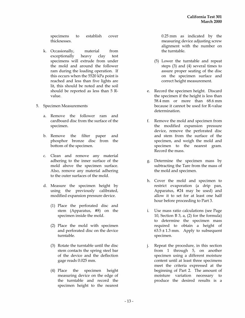
specimens to establish cover thicknesses.
k. Occasionally, material from
exceptionally heavy clay test specimens will extrude from under the mold and around the follower ram during the loading operation. If this occurs when the 5520 kPa point is reached and less than five lights are lit, this should be noted and the soil should be reported as less than 5 R-value.
5. Specimen Measurements
a. Remove the follower ram and
cardboard disc from the surface of the specimen.
b. Remove the filter paper and
phosphor bronze disc from the bottom of the specimen.
c. Clean and remove any material
adhering to the inner surface of the mold above the specimen surface. Also, remove any material adhering to the outer surfaces of the mold.
d. Measure the specimen height by
using the previously calibrated, modified expansion pressure device.
(1) Place the perforated disc and
stem (Apparatus, #8) on the specimen inside the mold.
(2) Place the mold with specimen
and perforated disc on the device turntable.
(3) Rotate the turntable until the disc
stem contacts the spring steel bar of the device and the deflection gage reads 0.025 mm.
(4) Place the specimen height
measuring device on the edge of the turntable and record the specimen height to the nearest
0.25 mm as indicated by the measuring device adjusting screw alignment with the number on the turntable.
(5) Lower the turntable and repeat
steps (3) and (4) several times to assure proper seating of the disc on the specimen surface and correct height measurement.
e. Record the specimen height. Discard
the specimen if the height is less than 58.4 mm or more than 68.6 mm because it cannot be used for R-value determination.
f. Remove the mold and specimen from
the modified expansion pressure device, remove the perforated disc and stem from the surface of the specimen, and weigh the mold and specimen to the nearest gram. Record the mass.
g. Determine the specimen mass by
subtracting the Tare from the mass of the mold and specimen.
h. Cover the mold and specimen to
restrict evaporation (a drip pan, Apparatus, #24 may be used) and allow it to set for at least one half hour before proceeding to Part 3.
i. Use mass ratio calculations (see Page
10, Section B 3, a, (2) for the formula) to determine the specimen mass required to obtain a height of 63.5 ± 1.3 mm. Apply to subsequent specimen.
j. Repeat the procedure, in this section
from 1 through 5, on another specimen using a different moisture content until at least three specimens meet the criteria expressed at the beginning of Part 2. The amount of moisture variation necessary to produce the desired results is a
California Test 301 March 2000
- 14 -
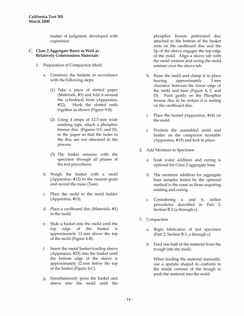
matter of judgment, developed with experience.
C. Class 2 Aggregate Bases as Well as
Relatively Cohesionless Materials
1. Preparation of Compaction Mold
a. Construct the baskets in accordance with the following steps:
(1) Take a piece of slotted paper
(Materials, #3) and fold it around the cylindrical form (Apparatus, #22). Hook the slotted ends together as shown (Figure 9-B).
(2) Using 4 strips of 12.7-mm wide
masking tape, attach a phosphor bronze disc, (Figures 9-C and D), to the paper so that the holes in the disc are not obscured in the process.
(3) The basket remains with the
specimen through all phases of the test procedures.
b. Weigh the basket with a mold
(Apparatus, #12) to the nearest gram and record the mass (Tare).
c. Place the mold in the mold holder
(Apparatus, #13). d. Place a cardboard disc (Materials, #1)
in the mold. e. Slide a basket into the mold until the
top edge of the basket is approximately 12 mm above the top of the mold (Figure 4-B).
f. Insert the metal basket-loading sleeve
(Apparatus, #23) into the basket until the bottom edge of the sleeve is approximately 12 mm below the top of the basket (Figure 4-C).
g. Simultaneously press the basket and
sleeve into the mold until the
phosphor bronze perforated disc attached to the bottom of the basket rests on the cardboard disc and the lip of the sleeve engages the top edge of the mold. Align a sleeve tab with the mold retainer and swing the mold retainer over the sleeve tab.
h. Raise the mold and clamp it in place
leaving approximately 3 mm clearance between the lower edge of the mold and base (Figure 4, C and D). Push gently on the Phosphor bronze disc to be certain it is resting on the cardboard disc.
i. Place the funnel (Apparatus, #14) on
the mold. j. Position the assembled mold and
holder on the compactor turntable (Apparatus, #15) and lock in place.
2. Add Moisture to Specimen
a. Soak water addition and curing is
optional for Class 2 aggregate base. b. The moisture addition for aggregate
base samples tested by the optional method is the same as those requiring soaking and curing.
c. Considering a and b, utilize
procedures described in Part 2, Section B-2 (a through c).
3. Compaction
a. Begin fabrication of test specimen (Part 2, Section B-3, a through c).
b. Feed one-half of the material from the
trough into the mold. When feeding the material manually,
use a spatula shaped to conform to the inside contour of the trough to push the material into the mold.
California Test 301 March 2000
- 15 -
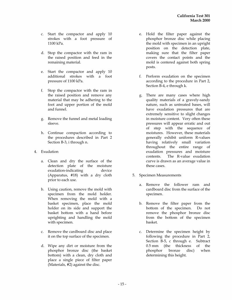
c. Start the compactor and apply 10 strokes with a foot pressure of 1100 kPa.
d. Stop the compactor with the ram in
the raised position and feed in the remaining material.
e. Start the compactor and apply 10
additional strokes with a foot pressure of 1100 kPa.
f. Stop the compactor with the ram in
the raised position and remove any material that may be adhering to the foot and upper portion of the mold and funnel.
g. Remove the funnel and metal loading
sleeve. h. Continue compaction according to
the procedures described in Part 2 Section B-3, i through n.
4. Exudation
a. Clean and dry the surface of the detection plate of the moisture exudation-indicating device (Apparatus, #18) with a dry cloth prior to each use.
b. Using caution, remove the mold with
specimen from the mold holder. When removing the mold with a basket specimen, place the mold holder on its side and support the basket bottom with a hand before uprighting and handling the mold with specimen.
c. Remove the cardboard disc and place
it on the top surface of the specimen. d. Wipe any dirt or moisture from the
phosphor bronze disc (the basket bottom) with a clean, dry cloth and place a single piece of filter paper (Materials, #2) against the disc.
e. Hold the filter paper against the phosphor bronze disc while placing the mold with specimen in an upright position on the detection plate, making sure that the filter paper covers the contact points and the mold is centered against both spring posts.
f. Perform exudation on the specimen
according to the procedure in Part 2, Section B-4, e through k.
g. There are many cases where high
quality materials of a gravely-sandy nature, such as untreated bases, will have exudation pressures that are extremely sensitive to slight changes in moisture content. Very often these pressures will appear erratic and out of step with the sequence of moistures. However, these materials generally exhibit uniform R-values having relatively small variation throughout the entire range of exudation pressures and moisture contents. The R-value exudation curve is drawn as an average value in these cases.
5. Specimen Measurements
a. Remove the follower ram and
cardboard disc from the surface of the specimen.
b. Remove the filter paper from the
bottom of the specimen. Do not remove the phosphor bronze disc from the bottom of the specimen basket.
c. Determine the specimen height by
following the procedure in Part 2, Section B-5, c through e. Subtract 0.5 mm (the thickness of the phosphor bronze disc) when determining this height.

California Test 301 March 2000
- 16 -
d. Determine the specimen mass by following the procedure in Part 2, Section B-5, f through i.
PART 3. DETERMINING THE EXPANSION
PRESSURE OF R-VALUE TEST SPECIMENS
A. Calibration of Expansion Pressure Devices
(Apparatus, #8). 1. The calibration procedure for the
expansion pressure device is described in California Test 103.
2. Expansion pressure devices should be
recalibrated at least once every two months.
3. Recalibrate any expansion pressure
device that has been used with materials that have developed such extreme pressure as to leave a permanent set in the spring steel bar. A deflection gage reading that exceeds 0.25 mm is sufficient to require re-calibration.
In general, specimens that contain
predominant amounts of silt or clay materials will develop the greatest expansion pressures.
4. Keep the gage surfaces on the top bar and
contact surfaces on the spring steel bar clean and polished. Since deflection measurements are taken to 0.002 mm, dust and corrosion on any of the gage contact points can result in erroneous measurements.
B. Adjustment of Expansion Pressure Device
1. Clean off all dust and foreign material
from the spring steel bar and adjustment plug.
2. Place deflection gage (Apparatus, #9) on
the top bar of expansion pressure device with the single bearing end resting on the adjustment plug.
3. Use an Allen wrench (Apparatus, #10) to adjust the plug until the deflection gage reads minus 0.025 mm.
4. Place a filter paper (Materials, #5) on the
turntable. 5. Place a pan (Apparatus, #24) under the
turntable. 6. Keep the expansion pressure devices free
from the influence of any source of vibration during the test. If shelving is used to hold the devices, do not attach or brace it to any of the building walls.
C. Test Procedure
1. Place a perforated disc and stem (Figure
2) on the specimen. 2. Place the mold containing the specimen
and perforated disc assembly on the filter paper covered turntable.
3. Seat the perforated disc firmly on
specimen with pressure applied from fingers.
4. Turn the turntable up until the dial
indicator is on zero. Exercise caution when raising the table
with the specimen in place and engaging the spring steel bar with the stem of the perforated disc assembly. If too much force is applied to the steel bar, a temporary set will ensue which will slowly relieve itself during the soaking period, and result in erroneous deflection readings.
5. Pour approximately 200 mL of water on
the specimen in the mold and allow to stand undisturbed for a normal test period of 16 to 24 h. This period may be extended over weekends or holidays for tests of untreated materials.
California Test 301 March 2000
- 17 -
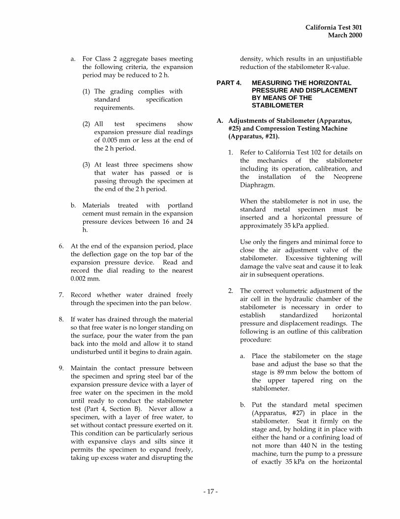
a. For Class 2 aggregate bases meeting the following criteria, the expansion period may be reduced to 2 h.
(1) The grading complies with
standard specification requirements.
(2) All test specimens show
expansion pressure dial readings of 0.005 mm or less at the end of the 2 h period.
(3) At least three specimens show
that water has passed or is passing through the specimen at the end of the 2 h period.
b. Materials treated with portland cement must remain in the expansion pressure devices between 16 and 24 h.
6. At the end of the expansion period, place
the deflection gage on the top bar of the expansion pressure device. Read and record the dial reading to the nearest 0.002 mm.
7. Record whether water drained freely
through the specimen into the pan below. 8. If water has drained through the material
so that free water is no longer standing on the surface, pour the water from the pan back into the mold and allow it to stand undisturbed until it begins to drain again.
9. Maintain the contact pressure between
the specimen and spring steel bar of the expansion pressure device with a layer of free water on the specimen in the mold until ready to conduct the stabilometer test (Part 4, Section B). Never allow a specimen, with a layer of free water, to set without contact pressure exerted on it. This condition can be particularly serious with expansive clays and silts since it permits the specimen to expand freely, taking up excess water and disrupting the
density, which results in an unjustifiable reduction of the stabilometer R-value.
PART 4. MEASURING THE HORIZONTAL
PRESSURE AND DISPLACEMENT BY MEANS OF THE STABILOMETER
A. Adjustments of Stabilometer (Apparatus,
#25) and Compression Testing Machine (Apparatus, #21). 1. Refer to California Test 102 for details on
the mechanics of the stabilometer including its operation, calibration, and the installation of the Neoprene Diaphragm.
When the stabilometer is not in use, the
standard metal specimen must be inserted and a horizontal pressure of approximately 35 kPa applied.
Use only the fingers and minimal force to
close the air adjustment valve of the stabilometer. Excessive tightening will damage the valve seat and cause it to leak air in subsequent operations.
2. The correct volumetric adjustment of the
air cell in the hydraulic chamber of the stabilometer is necessary in order to establish standardized horizontal pressure and displacement readings. The following is an outline of this calibration procedure:
a. Place the stabilometer on the stage
base and adjust the base so that the stage is 89 mm below the bottom of the upper tapered ring on the stabilometer.
b. Put the standard metal specimen
(Apparatus, #27) in place in the stabilometer. Seat it firmly on the stage and, by holding it in place with either the hand or a confining load of not more than 440 N in the testing machine, turn the pump to a pressure of exactly 35 kPa on the horizontal
California Test 301 March 2000
- 18 -
pressure gage. Adjust the turns displacement dial indicator to zero. Turn the pump handle clockwise at a rate of approximately two turns per second until the horizontal pressure gage reads 690 kPa. The turns displacement dial indicator shall read 2.00 ± 0.05 turns. If the reading is not within the specified limits, an air adjustment must be made by using the following procedure.
(1) Without moving the pump
handle, reset the dial indicator to 2.00.
(2) Turn the pump handle counter-
clockwise until the dial indicator reads zero.
(3) If the horizontal pressure gage
reads less than 35 kPa, use a rubber bulb to add air through the air adjustment valve on the stabilometer. Inject air into the stabilometer while using the fingers to open the valve. Close the valve when the gage reads 35 kPa.
(4) If the horizontal pressure gage
reads more than 35 kPa release some air by slowly opening and rapidly closing the valve. If too much air is released (indicated by a gage reading of less than 35 kPa), add some air. Close the valve when the gage reads 35 kPa.
(5) Repeat the turns displacement procedure until the specified turns displacement is obtained.
3. Adjust the testing machine to apply a load at the rate of 1.27 0.02 mm/min. On a machine with a moving base, this adjustment must be performed with the stabilometer and stage base on the platen and no load applied. The hydraulic testing machines must be run several
minutes so that the oil warms sufficiently to maintain a constant speed.
B. Test Procedure
1. Adhere to the following precautions:
a. The stabilometer test must be
performed within one hour of pouring off the excess water after completion of the expansion pressure test.
b. Care must be exercised to avoid
disrupting the compacted specimen while transferring it from the mold to the stabilometer. This applies particularly to those samples composed of coarse granular materials. A test specimen which has been destructively disrupted due to rough handling, transfer from the mold to stabilometer, or as a result of the test itself, will exhibit excessively high horizontal pressure and turns displacement readings.
c. Substitution of a cage or vane type
follower for the specified solid-wall follower will result in high displacement readings and may rupture the stabilometer diaphragm.
d. The horizontal pressure gage on the
stabilometer can be damaged if the vertical load on soft, fluid materials exceeds 8900 N.
2. After completing the expansion pressure
test, remove the mold containing the specimen from the expansion pressure device.
a. Pour off the water from the top of the
specimen. b. Keep the mold containing the
specimen covered if the stabilometer test is not performed immediately.
California Test 301 March 2000
- 19 -
3. Remove the standard metal specimen from the stabilometer.
4. Lock the stabilometer to the stage base
and place a cardboard disc on the stage. 5. Position the mold and test specimen on
top of the stabilometer and place a cardboard disc on top of the specimen.
6. Place the specimen follower (Apparatus,
#28) on top of the specimen and push the specimen from the mold directly into the stabilometer.
7. Center the stabilometer under the
spherically seated head of the testing machine. If a locking shim was used during exudation, remove it.
8. Bring the head of the testing machine into
contact with the follower but do not apply any load.
9. Apply a horizontal pressure of 35 kPa to
the test specimen by turning the pump handle.
10. Apply a vertical load to the test specimen
at the calibrated rate of 1.3 mm per min.
11. When the vertical load reaches 8900 N, read and record the horizontal pressure.
12. Immediately reduce the vertical load to
4450 N. 13. Reduce the horizontal pressure to 35 kPa
by turning the pump handle counter clockwise.
Reducing the horizontal pressure will
result in a further reduction of the vertical load. This is normal and is to be ignored.
14. Set the turns displacement indicator to
zero. 15. Turn the pump handle clockwise at a rate
of approximately two turns per second until the stabilometer gage reads 690 kPa.
During this operation, the vertical load
will increase and may exceed the initial 4450 N load. This is normal and is to be ignored.
16. Read the turns displacement dial
indicator measurement to the nearest 0.01 revolution.
17. Record the turns displacement of the
specimen.
18. Release the vertical load on the testing machine.
19. Release the horizontal pressure on the
stabilometer by turning the pump handle counter clockwise.
20. Remove the specimen from the
stabilometer by lifting the stabilometer from the stage base.
21. The specimen may be discarded. 22. Clean the interior of the stabilometer. 23. Continue testing additional specimens
beginning with Step 3 of this procedure.
C. Stabilometer Maintenance 1. Clean interior and exterior of stabilometer
with a damp cloth or sponge after testing is completed and wipe dry with a clean cloth.
2. Inspect the stabilometer, including the
neoprene diaphragm, for obvious anomalies such as oil leaks and excessive wear as described in California Test 102.
3. Dust the neoprene diaphragm with
talcum powder, insert the standard metal specimen, and apply a horizontal pressure of approximately 35 kPa.
California Test 301 March 2000
- 20 -
PART 5. CALCULATING THE MOISTURE CONTENT AND DENSITY OF R-VALUE TEST SPECIMENS
A. Form TL-0361 Calculations
The calculations in the following sections are the procedures used for completing calculations on Form TL-0361 (Figure 13). The notations between quotation marks, in these sections, conform to notations on the form.
B. Moisture Calculations 1. The "INITIAL MOISTURE %" is
determined on a specimen (Part 1, Section C-3).
2. Determine the "WATER ADDED - ML
(TOTAL)" by summing "SOAK WATER - ML" (Part 1, Section D-1, c through f) and the water added for saturation (Part 2, Section B-2) for each specimen.
3. Calculate the "WATER ADDED %" to the
nearest 0.1 % for each test specimen by the following formula:
M2 = W (100 + M1)/W1
where:
M
2 = "WATER ADDED %"
W = "WATER ADDED-ML
(TOTAL)" M
1 = "INITIAL MOISTURE %"
W
1 = Original specimen batch mass
in grams
4. Calculate the "MOISTURE AT COMPACTION %" for each test specimen by the following formula:
M = M
1 + M
2
where:
M = "MOISTURE AT COMPACTION %"
M1 = "INITIAL MOISTURE %"
M2 = "WATER ADDED %"
C. Density Calculations
1. Calculate the "DRY DENSITY BRIQ. -
kg/m3" for each test specimen by the following formula:
D = 1.234 x 10⁴W2/(100 + M)H
where:
D = "DRY DENSITY BRIQ. -kg/m3"
W2 = "WET MASS OF BRIQUETTE - GMs", the mass in grams of the specimen after compaction (Part 2. Section B-5, f and g).
M = MOISTURE AT COMPACTION %"
H = "HEIGHT OF BRIQUETTE - mm", the height of test specimen as determined in Part 2, Section B-5d or Part 2, Section C-5c (for specimens fabricated in a basket).
PART 6. DETERMINING THE R-VALUE OF A
MATERIAL
The R-value of a material is determined as described in the following sections. The description follows the steps used in completing Form TL-0361 (Figure 13). The notations within quotation marks in these sections conform to the notations on the form.
A. Determining the R-value of a material by the stabilometer. 1. Calculate the R-value, using the following
formula:
California Test 301 March 2000
- 21 -
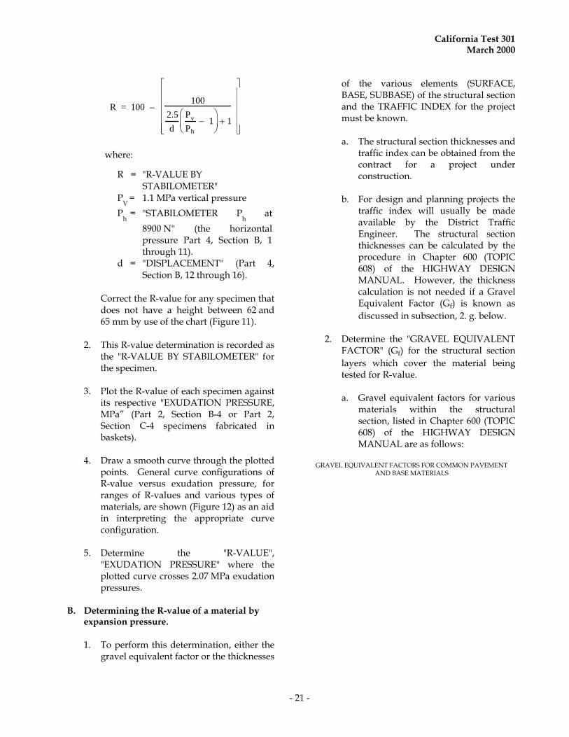
R = 100 – 100
2.5
d
Pv
Ph
1
1
where:
R = "R-VALUE BY STABILOMETER"
PV
= 1.1 MPa vertical pressure
Ph
= "STABILOMETER Ph at
8900 N" (the horizontal pressure Part 4, Section B, 1 through 11).
d = "DISPLACEMENT" (Part 4, Section B, 12 through 16).
Correct the R-value for any specimen that
does not have a height between 62 and 65 mm by use of the chart (Figure 11).
2. This R-value determination is recorded as
the "R-VALUE BY STABILOMETER" for the specimen.
3. Plot the R-value of each specimen against
its respective "EXUDATION PRESSURE, MPa” (Part 2, Section B-4 or Part 2, Section C-4 specimens fabricated in baskets).
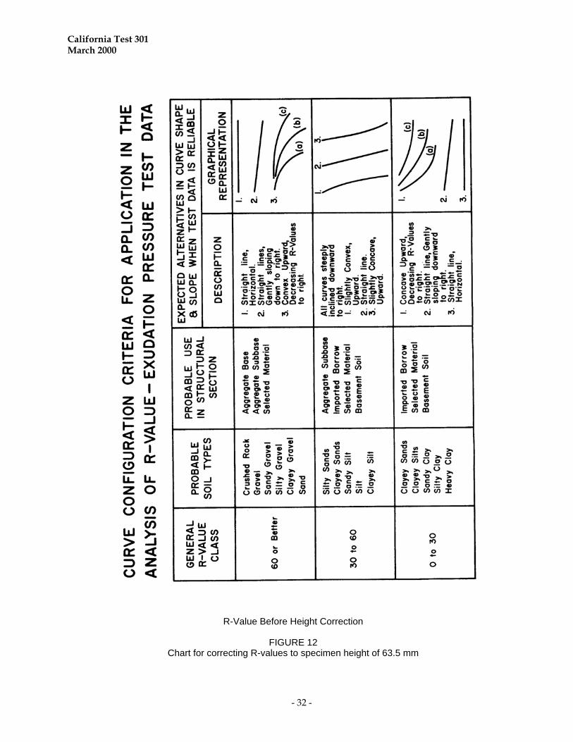
4. Draw a smooth curve through the plotted
points. General curve configurations of R-value versus exudation pressure, for ranges of R-values and various types of materials, are shown (Figure 12) as an aid in interpreting the appropriate curve configuration.
5. Determine the "R-VALUE",
"EXUDATION PRESSURE" where the plotted curve crosses 2.07 MPa exudation pressures.
B. Determining the R-value of a material by
expansion pressure. 1. To perform this determination, either the
gravel equivalent factor or the thicknesses
of the various elements (SURFACE, BASE, SUBBASE) of the structural section and the TRAFFIC INDEX for the project must be known.
a. The structural section thicknesses and
traffic index can be obtained from the contract for a project under construction.
b. For design and planning projects the
traffic index will usually be made available by the District Traffic Engineer. The structural section thicknesses can be calculated by the procedure in Chapter 600 (TOPIC 608) of the HIGHWAY DESIGN MANUAL. However, the thickness calculation is not needed if a Gravel Equivalent Factor (Gf) is known as discussed in subsection, 2. g. below.
2. Determine the "GRAVEL EQUIVALENT
FACTOR" (Gf) for the structural section layers which cover the material being tested for R-value.
a. Gravel equivalent factors for various
materials within the structural section, listed in Chapter 600 (TOPIC 608) of the HIGHWAY DESIGN MANUAL are as follows:
GRAVEL EQUIVALENT FACTORS FOR COMMON PAVEMENT
AND BASE MATERIALS
California Test 301 March 2000
- 22 -
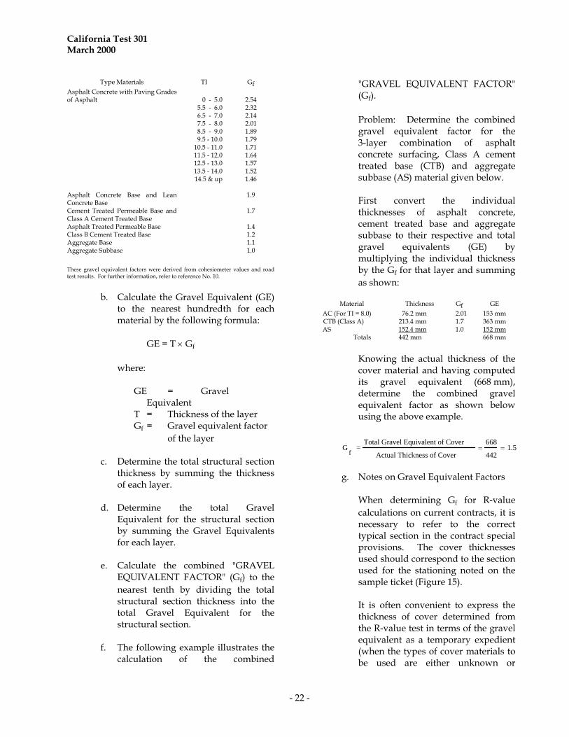
Type Materials TI Gf Asphalt Concrete with Paving Grades of Asphalt
0 - 5.0
2.54
5.5 - 6.0 2.32 6.5 - 7.0 2.14 7.5 - 8.0 2.01 8.5 - 9.0 1.89 9.5 - 10.0 1.79 10.5 - 11.0 1.71 11.5 - 12.0 1.64 12.5 - 13.0 1.57 13.5 - 14.0 1.52 Asphalt Concrete Base and Lean Concrete Base
14.5 & up 1.46
1.9
Cement Treated Permeable Base and Class A Cement Treated Base
1.7
Asphalt Treated Permeable Base 1.4 Class B Cement Treated Base 1.2 Aggregate Base 1.1 Aggregate Subbase 1.0
These gravel equivalent factors were derived from cohesiometer values and road test results. For further information, refer to reference No. 10.
b. Calculate the Gravel Equivalent (GE)
to the nearest hundredth for each material by the following formula:
GE = T Gf
where:
GE = Gravel
Equivalent T = Thickness of the layer Gf = Gravel equivalent factor
of the layer
c. Determine the total structural section thickness by summing the thickness of each layer.
d. Determine the total Gravel
Equivalent for the structural section by summing the Gravel Equivalents for each layer.
e. Calculate the combined "GRAVEL
EQUIVALENT FACTOR" (Gf) to the nearest tenth by dividing the total structural section thickness into the total Gravel Equivalent for the structural section.
f. The following example illustrates the
calculation of the combined
"GRAVEL EQUIVALENT FACTOR" (Gf).
Problem: Determine the combined
gravel equivalent factor for the 3-layer combination of asphalt concrete surfacing, Class A cement treated base (CTB) and aggregate subbase (AS) material given below.
First convert the individual
thicknesses of asphalt concrete, cement treated base and aggregate subbase to their respective and total gravel equivalents (GE) by multiplying the individual thickness by the Gf for that layer and summing as shown:
Material Thickness Gf GE AC (For TI = 8.0) 76.2 mm 2.01 153 mm
CTB (Class A) 213.4 mm 1.7 363 mm AS 152.4 mm 1.0 152 mm
Totals 442 mm 668 mm
Knowing the actual thickness of the
cover material and having computed its gravel equivalent (668 mm), determine the combined gravel equivalent factor as shown below using the above example.
G
f =
Total Gravel Equivalent of Cover
Actual Thickness of Cover
668
442 1.5
g. Notes on Gravel Equivalent Factors When determining Gf for R-value
calculations on current contracts, it is necessary to refer to the correct typical section in the contract special provisions. The cover thicknesses used should correspond to the section used for the stationing noted on the sample ticket (Figure 15).
It is often convenient to express the
thickness of cover determined from the R-value test in terms of the gravel equivalent as a temporary expedient (when the types of cover materials to be used are either unknown or

California Test 301 March 2000
- 23 -
uncertain). The gravel equivalent, as the name implies, is the thickness of gravel required to support a given load, and is based upon a gravel equivalent factor of 1.0 for the cover material. One of the principal advantages in using the gravel equivalent is that it indicates to the designer what maximum thicknesses will be required to meet the conditions of the soil and traffic of the proposed project. Since a Gf of 1.0 is the lowest value used for design purposes, use of 1.0 will result in the determination of the highest theoretical thickness requirements for a given R-value and traffic index. Likewise, any subsequent increase in the gravel equivalent factor will always reduce the design thickness requirement.
The design equation is not applicable
to the design of portland cement concrete pavements and no gravel equivalent factor is given for concrete. Generally, the untreated materials under portland cement concrete pavement extend under the shoulder area. Therefore, when testing materials which underlie portland cement concrete pavements, the traffic index and gravel equivalent factors of the applicable layers of the shoulder structural section should be used for calculating R-value by expansion pressure.
If the values used for TI and Gf in the
calculation of the R-value by expansion pressure are modified later, the R-value must be recalculated.
3. Calculate the "THICK. BY STAB. mm"
(thickness of cover material indicated by the stabilometer) for each specimen using the following formula:
T = [0.975(TI)(100-R)]/Gf
where: T = "THICK. BY STAB. mm" TI = Traffic index R = "R-VALUE BY
STABILOMETER" for each specimen calculated in Section B-1.
Gf = "COMBINED GRAVEL EQUIVALENT FACTOR" as calculated above.
4. Calculate the "THICK. BY EXP. PRESS.
mm" (thickness of cover required by expansion pressure) for each specimen using the following formula:
T = [Dial Reading x 100 x 4]x2100/W where: T = "THICK. BY EXP. PRESS. mm" Dial Reading = "EXPANSION DIAL
READING" (Part 3, Section C, 1 through 6)
W = Unit mass of cover over
material being tested. (Generally, W for structural
sections of asphalt concrete, base, and subbase average about 2100 kg/m3. However, lighter materials could be less and structural sections of asphalt concrete and base or asphalt concrete would probably be higher).
5. Plot the "THICK. BY STAB. mm"
(thickness indicated by stabilometer) against the "THICK. BY EXP. PRESS. mm" (thickness indicated by expansion pressure) on a graph with a balance line drawn through the points where both thickness values of the graph are equal.
California Test 301 March 2000
- 24 -
6. Draw a smooth curve through the plotted points representing each specimen.
7. Determine the thickness where the curve
crosses the balance line. At this point both the “THICK. BY STAB. mm” and “THICK. BY EXP. PRESS mm” are equal.
8. Determine the "R-VALUE",
"EXPANSION PRESSURE" using the following formula:
R = 100 - [Gf(T)]/[.975(TI)] where:
R = "R-VALUE", "EXPANSION PRESSURE"
Gf = "GRAVEL EQUIVALENT FACTOR"
T = Thickness where curve crosses the balance line determined in 7 above.
TI = TRAFFIC INDEX
9. The "R-VALUE", "AT EQUILIBRIUM" which is the lowest of the two R-values determined in Steps 5 (EXUDATION PRESSURE) and 8 (EXPANSION PRESSURE), is the R-value of the sample.
10. If the expansion pressure in pascals is
needed, it may be determined by the following formula:
Expansion Pressure =
20.5 x Dial Reading x 4000
PART 7. REPORTING RESULTS
Report all information pertinent to the submitted sample. This includes the following: 1. As received and as used gradations. 2. Data relating to the test specimens. 3. Measured test data.
4. Data obtained for and established by calculations.
5. Test result calculations and
determination.
A. Test Report Form TL-0361 1. This is an appropriate form for reporting
of test results. 2. The face of the form (Figure 13) contains
labeled spaces for entering information.
a. All applicable information shall be entered on the form.
b. The form contains graphs for R-value
determinations. These graphs are intended as an aid in determining R-values and will normally not appear on a copy of the test report because they are covered by the sample identification card (Form T-101) (Figure 15) which is submitted with the sample.
c. The graph for cover thickness is not
always of sufficient size for plotting the thicknesses used in determining expansion pressure R-values. The scale notations and even the balance line may have to be revised or a larger sheet of graph paper may be used to fit the data.
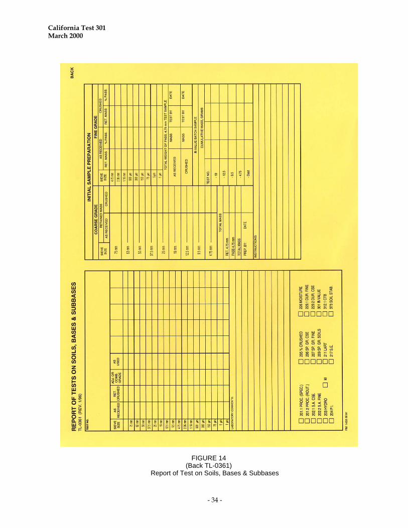
3. The back of the form (Figure 14) contains
spaces for gradation and batching calculations. This side of the form is intended as a worksheet and is normally not reported.
If other forms are used they shall contain all the information that would be reported on Form TL-0361.
California Test 301 March 2000
- 25 -
REFERENCES California Tests 201, 202, 226, 101, 102, 103, 104, 105, 108 California DOT Highway Design Manual "Thickness of Flexible Pavements by the California Formula Compared to AASHTO Road Test Data", F.N. Hveem and G.B. Sherman. Proceedings Highway Research Board, 1963.
End of Text (California Test 301 contains 30 Pages)
California Test 301 March 2000
- 26 -
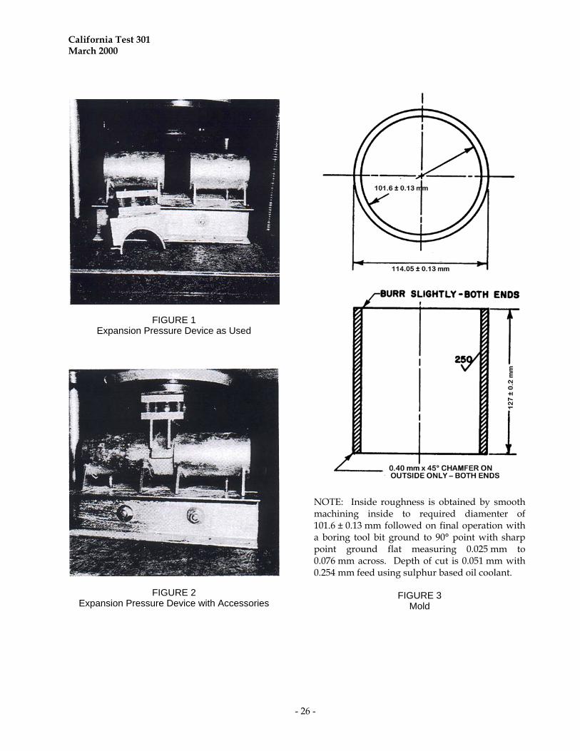
FIGURE 1 Expansion Pressure Device as Used
FIGURE 2 Expansion Pressure Device with Accessories
NOTE: Inside roughness is obtained by smooth machining inside to required diamenter of 101.6 ± 0.13 mm followed on final operation with a boring tool bit ground to 90° point with sharp point ground flat measuring 0.025 mm to 0.076 mm across. Depth of cut is 0.051 mm with 0.254 mm feed using sulphur based oil coolant.
FIGURE 3 Mold
California Test 301 March 2000
- 27 -
A
C
B
D
FIGURE 4
California Test 301 March 2000
- 28 -
Mold Holder with Metal Basket Loading Sleeve
FIGURE 5 Funnel and Trough
FIGURE 6 Moisture Exudation Device
FIGURE 7
Perforated Disc
California Test 301 March 2000
- 29 -
FIGURE 8 R-Value Test Peper Basket Materials
FIGURE 9
California Test 301 March 2000
- 30 -
Basket Making Device
FIGURE 10 Stabilometer

California Test 301 March 2000
- 31 -
CHART FOR CORRECTING R-VALUES TO SPECIMEN HEIGHT OF 63.5 MM
Height correction should be made using the chart below. NOTE: No correction for specimen heights between 62.0 mm and 65.0 mm. Interpolate R-value corrections
for other heights. Example: Overall height of 67.3 mm R-value (uncorrected) = 50 R-value (corrected) = 54
R-V
alue
Cor
rect
ed
FIGURE 11
R-Value Before Height Correction
California Test 301 March 2000
- 32 -
R-Value Before Height Correction
FIGURE 12
Chart for correcting R-values to specimen height of 63.5 mm

California Test 301 March 2000
- 33 -
FIGURE 13 (Front TL – 0361)
Report of Test on Soils, Bases & Subbases
California Test 301 March 2000
- 34 -
FIGURE 14 (Back TL-0361)
Report of Test on Soils, Bases & Subbases

California Test 301 March 2000
- 35 -
FIGURE 15 Form TL-101