Embed Size (px)
Citation preview

BBYY
Trike Conversion Kit
2014 - Current
FLHT Series Harley-Davidson
Installation Instructions
REVISED 4 - 2017
California Sidecar Parts & Technical Support
434.263.8866

2
3
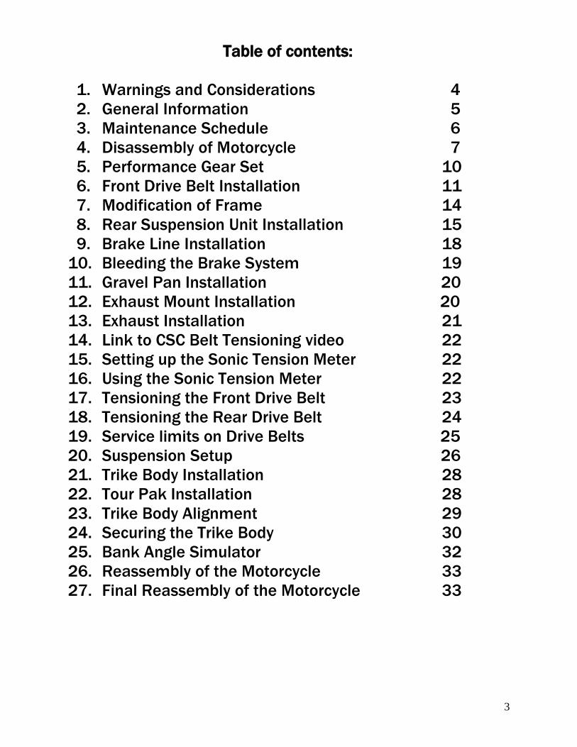
Table of contents:
1. Warnings and Considerations 4
2. General Information 5
3. Maintenance Schedule 6
4. Disassembly of Motorcycle 7
5. Performance Gear Set 10
6. Front Drive Belt Installation 11
7. Modification of Frame 14
8. Rear Suspension Unit Installation 15
9. Brake Line Installation 18
10. Bleeding the Brake System 19
11. Gravel Pan Installation 20
12. Exhaust Mount Installation 20
13. Exhaust Installation 21
14. Link to CSC Belt Tensioning video 22
15. Setting up the Sonic Tension Meter 22
16. Using the Sonic Tension Meter 22
17. Tensioning the Front Drive Belt 23
18. Tensioning the Rear Drive Belt 24
19. Service limits on Drive Belts 25
20. Suspension Setup 26
21. Trike Body Installation 28
22. Tour Pak Installation 28
23. Trike Body Alignment 29
24. Securing the Trike Body 30
25. Bank Angle Simulator 32
26. Reassembly of the Motorcycle 33
27. Final Reassembly of the Motorcycle 33
4
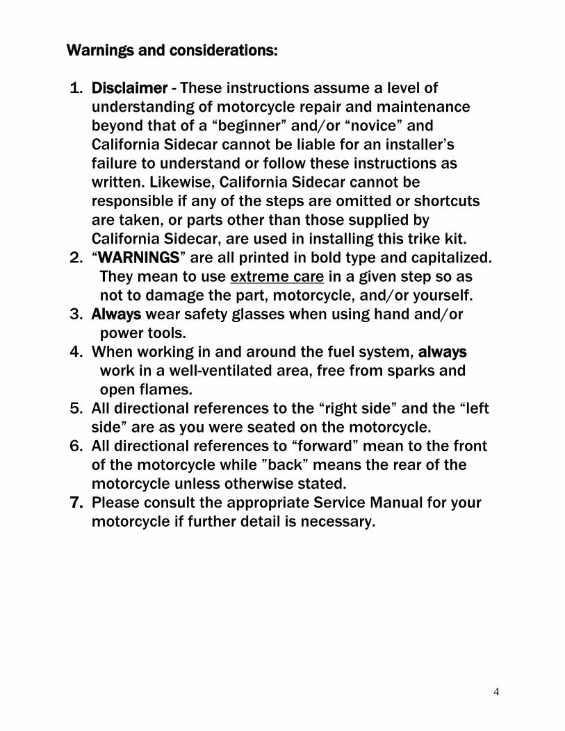
Warnings and considerations:
1. Disclaimer - These instructions assume a level of
understanding of motorcycle repair and maintenance
beyond that of a “beginner” and/or “novice” and
California Sidecar cannot be liable for an installer’s
failure to understand or follow these instructions as
written. Likewise, California Sidecar cannot be
responsible if any of the steps are omitted or shortcuts
are taken, or parts other than those supplied by
California Sidecar, are used in installing this trike kit.
2. “WARNINGS” are all printed in bold type and capitalized.
They mean to use extreme care in a given step so as
not to damage the part, motorcycle, and/or yourself.
3. Always wear safety glasses when using hand and/or
power tools.
4. When working in and around the fuel system, always
work in a well-ventilated area, free from sparks and
open flames.
5. All directional references to the “right side” and the “left
side” are as you were seated on the motorcycle.
6. All directional references to “forward” mean to the front
of the motorcycle while ”back” means the rear of the
motorcycle unless otherwise stated.
7. Please consult the appropriate Service Manual for your
motorcycle if further detail is necessary.
5
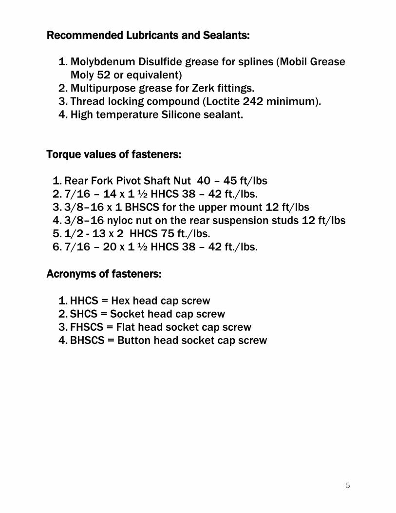
Recommended Lubricants and Sealants:
1. Molybdenum Disulfide grease for splines (Mobil Grease
Moly 52 or equivalent)
2. Multipurpose grease for Zerk fittings.
3. Thread locking compound (Loctite 242 minimum).
4. High temperature Silicone sealant.
Torque values of fasteners:
1. Rear Fork Pivot Shaft Nut 40 – 45 ft/lbs
2. 7/16 – 14 x 1 ½ HHCS 38 – 42 ft./lbs.
3. 3/8–16 x 1 BHSCS for the upper mount 12 ft/lbs
4. 3/8–16 nyloc nut on the rear suspension studs 12 ft/lbs
5. 1/2 - 13 x 2 HHCS 75 ft./lbs.
6. 7/16 – 20 x 1 ½ HHCS 38 – 42 ft./lbs.
Acronyms of fasteners:
1. HHCS = Hex head cap screw
2. SHCS = Socket head cap screw 3. FHSCS = Flat head socket cap screw 4. BHSCS = Button head socket cap screw
6
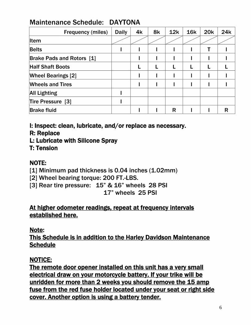
Maintenance Schedule: DAYTONA Frequency (miles) Daily 4k 8k 12k 16k 20k 24k
Item
Belts I I I I I T I
Brake Pads and Rotors [1] I I I I I I
Half Shaft Boots L L L L L L
Wheel Bearings [2] I I I I I I
Wheels and Tires I I I I I I
All Lighting I
Tire Pressure [3] I
Brake fluid I I R I I R
I: Inspect: clean, lubricate, and/or replace as necessary.
R: Replace
L: Lubricate with Silicone Spray
T: Tension
NOTE:
[1] Minimum pad thickness is 0.04 inches (1.02mm)
[2] Wheel bearing torque: 200 FT.-LBS.
[3] Rear tire pressure: 15” & 16” wheels 28 PSI
17” wheels 25 PSI
At higher odometer readings, repeat at frequency intervals
established here.
Note:
This Schedule is in addition to the Harley Davidson Maintenance
Schedule
NOTICE:
The remote door opener installed on this unit has a very small
electrical draw on your motorcycle battery. If your trike will be
unridden for more than 2 weeks you should remove the 15 amp
fuse from the red fuse holder located under your seat or right side
cover. Another option is using a battery tender.
7
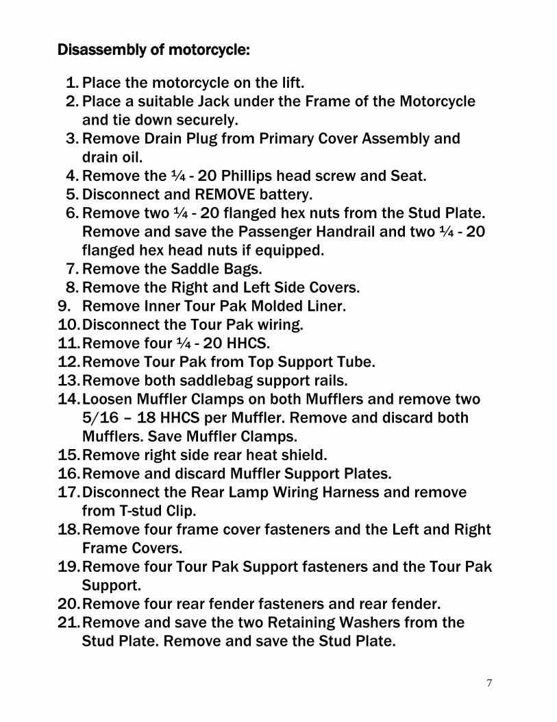
Disassembly of motorcycle:
1. Place the motorcycle on the lift.
2. Place a suitable Jack under the Frame of the Motorcycle
and tie down securely.
3. Remove Drain Plug from Primary Cover Assembly and
drain oil.
4. Remove the ¼ - 20 Phillips head screw and Seat.
5. Disconnect and REMOVE battery.
6. Remove two ¼ - 20 flanged hex nuts from the Stud Plate.
Remove and save the Passenger Handrail and two ¼ - 20
flanged hex head nuts if equipped.
7. Remove the Saddle Bags.
8. Remove the Right and Left Side Covers.
9. Remove Inner Tour Pak Molded Liner.
10. Disconnect the Tour Pak wiring.
11. Remove four ¼ - 20 HHCS.
12. Remove Tour Pak from Top Support Tube.
13. Remove both saddlebag support rails.
14. Loosen Muffler Clamps on both Mufflers and remove two
5/16 – 18 HHCS per Muffler. Remove and discard both
Mufflers. Save Muffler Clamps.
15. Remove right side rear heat shield.
16. Remove and discard Muffler Support Plates.
17. Disconnect the Rear Lamp Wiring Harness and remove
from T-stud Clip.
18. Remove four frame cover fasteners and the Left and Right
Frame Covers.
19. Remove four Tour Pak Support fasteners and the Tour Pak
Support.
20. Remove four rear fender fasteners and rear fender.
21. Remove and save the two Retaining Washers from the
Stud Plate. Remove and save the Stud Plate.
8
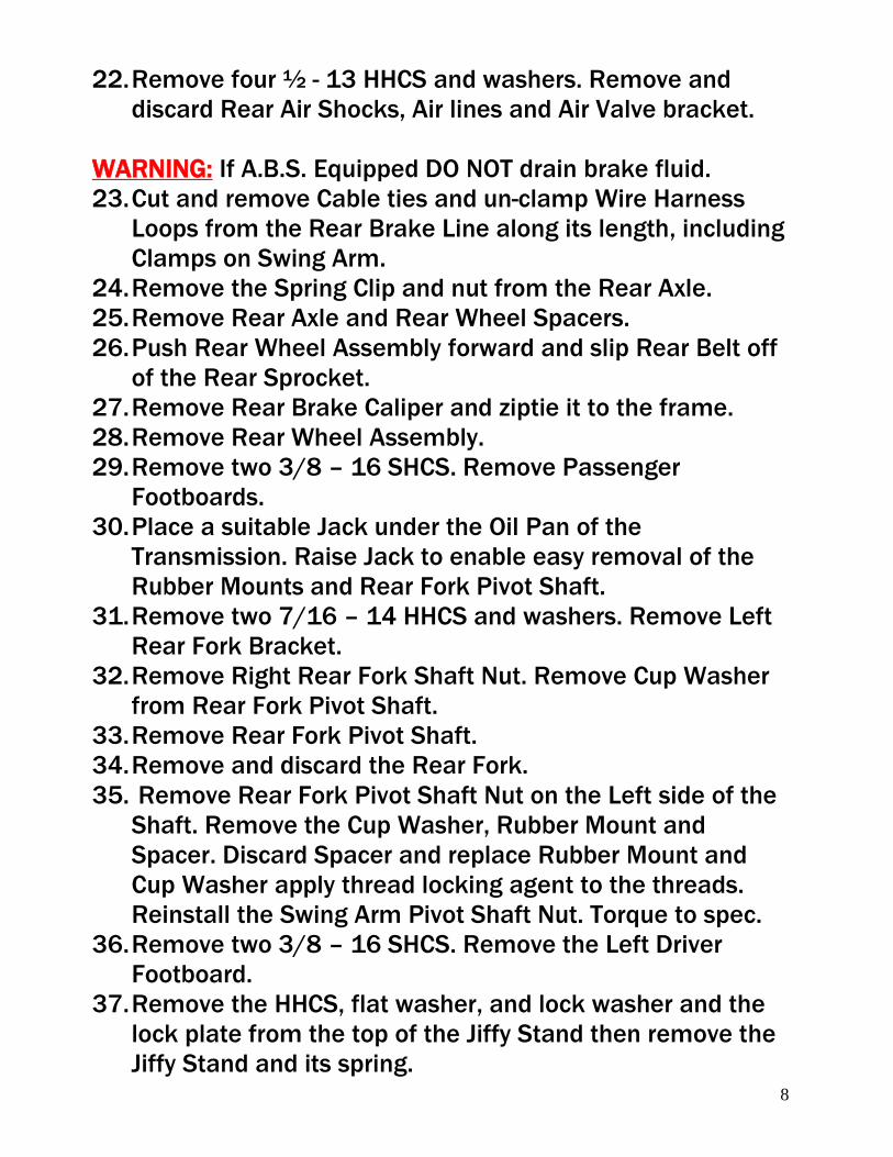
22. Remove four ½ - 13 HHCS and washers. Remove and
discard Rear Air Shocks, Air lines and Air Valve bracket.
WARNING: If A.B.S. Equipped DO NOT drain brake fluid.
23. Cut and remove Cable ties and un-clamp Wire Harness
Loops from the Rear Brake Line along its length, including
Clamps on Swing Arm.
24. Remove the Spring Clip and nut from the Rear Axle.
25. Remove Rear Axle and Rear Wheel Spacers.
26. Push Rear Wheel Assembly forward and slip Rear Belt off
of the Rear Sprocket.
27. Remove Rear Brake Caliper and ziptie it to the frame.
28. Remove Rear Wheel Assembly.
29. Remove two 3/8 – 16 SHCS. Remove Passenger
Footboards.
30. Place a suitable Jack under the Oil Pan of the
Transmission. Raise Jack to enable easy removal of the
Rubber Mounts and Rear Fork Pivot Shaft.
31. Remove two 7/16 – 14 HHCS and washers. Remove Left
Rear Fork Bracket.
32. Remove Right Rear Fork Shaft Nut. Remove Cup Washer
from Rear Fork Pivot Shaft.
33. Remove Rear Fork Pivot Shaft.
34. Remove and discard the Rear Fork.
35. Remove Rear Fork Pivot Shaft Nut on the Left side of the
Shaft. Remove the Cup Washer, Rubber Mount and
Spacer. Discard Spacer and replace Rubber Mount and
Cup Washer apply thread locking agent to the threads.
Reinstall the Swing Arm Pivot Shaft Nut. Torque to spec.
36. Remove two 3/8 – 16 SHCS. Remove the Left Driver
Footboard.
37. Remove the HHCS, flat washer, and lock washer and the
lock plate from the top of the Jiffy Stand then remove the
Jiffy Stand and its spring.
9
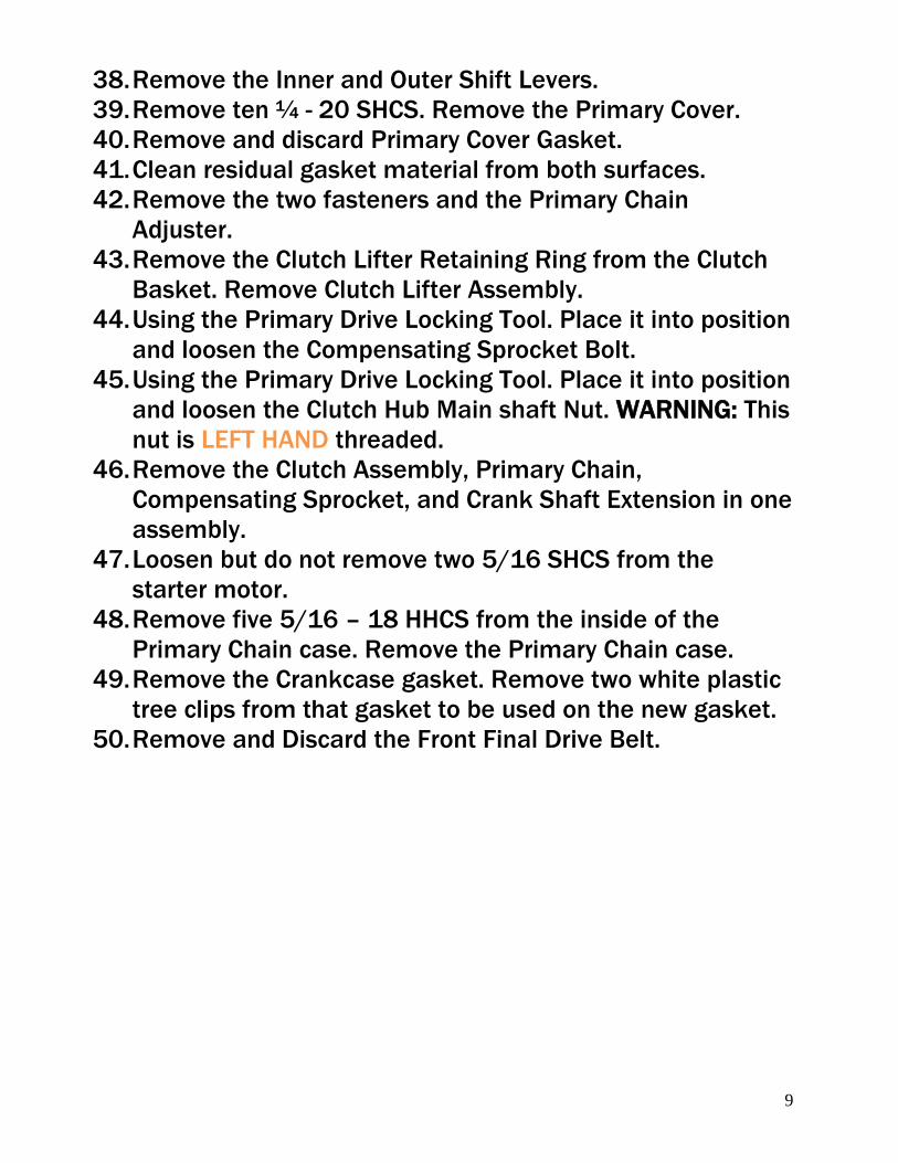
38. Remove the Inner and Outer Shift Levers.
39. Remove ten ¼ - 20 SHCS. Remove the Primary Cover.
40. Remove and discard Primary Cover Gasket.
41. Clean residual gasket material from both surfaces.
42. Remove the two fasteners and the Primary Chain
Adjuster.
43. Remove the Clutch Lifter Retaining Ring from the Clutch
Basket. Remove Clutch Lifter Assembly.
44. Using the Primary Drive Locking Tool. Place it into position
and loosen the Compensating Sprocket Bolt.
45. Using the Primary Drive Locking Tool. Place it into position
and loosen the Clutch Hub Main shaft Nut. WARNING: This
nut is LEFT HAND threaded.
46. Remove the Clutch Assembly, Primary Chain,
Compensating Sprocket, and Crank Shaft Extension in one
assembly.
47. Loosen but do not remove two 5/16 SHCS from the
starter motor.
48. Remove five 5/16 – 18 HHCS from the inside of the
Primary Chain case. Remove the Primary Chain case.
49. Remove the Crankcase gasket. Remove two white plastic
tree clips from that gasket to be used on the new gasket.
50. Remove and Discard the Front Final Drive Belt.
10
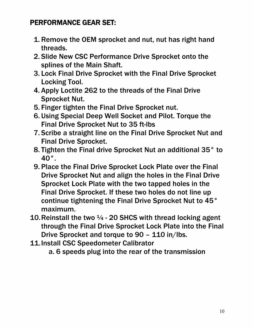
PERFORMANCE GEAR SET:
1. Remove the OEM sprocket and nut, nut has right hand
threads.
2. Slide New CSC Performance Drive Sprocket onto the
splines of the Main Shaft.
3. Lock Final Drive Sprocket with the Final Drive Sprocket
Locking Tool.
4. Apply Loctite 262 to the threads of the Final Drive
Sprocket Nut.
5. Finger tighten the Final Drive Sprocket nut.
6. Using Special Deep Well Socket and Pilot. Torque the
Final Drive Sprocket Nut to 35 ft-lbs
7. Scribe a straight line on the Final Drive Sprocket Nut and
Final Drive Sprocket.
8. Tighten the Final drive Sprocket Nut an additional 35° to
40°.
9. Place the Final Drive Sprocket Lock Plate over the Final
Drive Sprocket Nut and align the holes in the Final Drive
Sprocket Lock Plate with the two tapped holes in the
Final Drive Sprocket. If these two holes do not line up
continue tightening the Final Drive Sprocket Nut to 45°
maximum.
10. Reinstall the two ¼ - 20 SHCS with thread locking agent
through the Final Drive Sprocket Lock Plate into the Final
Drive Sprocket and torque to 90 – 110 in/lbs.
11. Install CSC Speedometer Calibrator
a. 6 speeds plug into the rear of the transmission
11
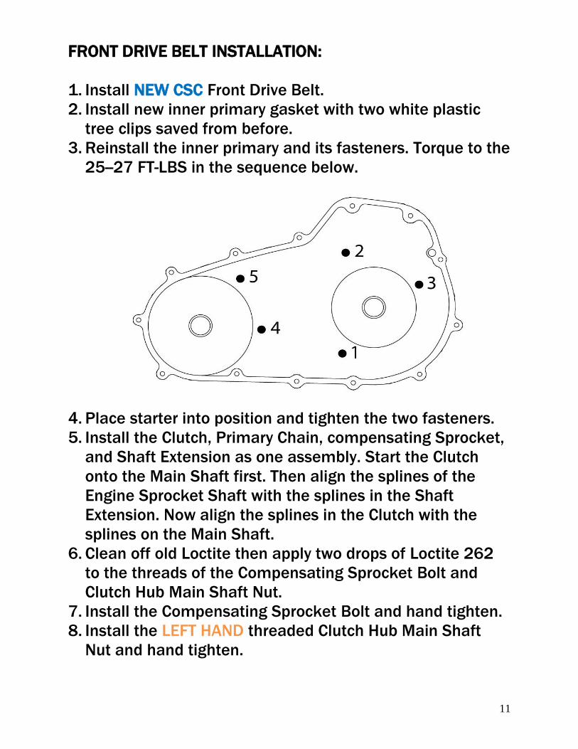
FRONT DRIVE BELT INSTALLATION:
1. Install NEW CSC Front Drive Belt.
2. Install new inner primary gasket with two white plastic
tree clips saved from before.
3. Reinstall the inner primary and its fasteners. Torque to the
25--27 FT-LBS in the sequence below.
4. Place starter into position and tighten the two fasteners.
5. Install the Clutch, Primary Chain, compensating Sprocket,
and Shaft Extension as one assembly. Start the Clutch
onto the Main Shaft first. Then align the splines of the
Engine Sprocket Shaft with the splines in the Shaft
Extension. Now align the splines in the Clutch with the
splines on the Main Shaft.
6. Clean off old Loctite then apply two drops of Loctite 262
to the threads of the Compensating Sprocket Bolt and
Clutch Hub Main Shaft Nut.
7. Install the Compensating Sprocket Bolt and hand tighten.
8. Install the LEFT HAND threaded Clutch Hub Main Shaft
Nut and hand tighten.
12
9. Using the Primary Drive Locking Tool. Torque the
Compensating Sprocket Bolt to 100 FT-LBS then loosen
bolt one full turn. Then final torque is 175 FT-LBS.
10. Using the Primary Drive Locking Tool. Torque the Clutch
Hub Nut to 70--80 FT-LBS. WARNING: This nut is LEFT
HAND threaded.
11. Remove the Primary Drive Locking Tool.
12. Place the Clutch Release Plate into the Clutch with the
stamped word “OUT” facing outwards.
13. Install the Retaining Ring into the bore of the Clutch Hub.
Ensure the Retaining Ring is fully seated in to the Clutch
Hub groove.
14. Install the Primary Chain Adjuster with its fasteners and
tighten.
15. Hang new Primary Chain Case Cover Gasket on Dowels.
16. Install the Outer Primary Chain Case Cover over the
Primary Chain Case Cover Gasket.
17. Start thirteen ¼ - 20 SHCS with ¼ flat washers into the
Outer Primary Chain Case Cover.
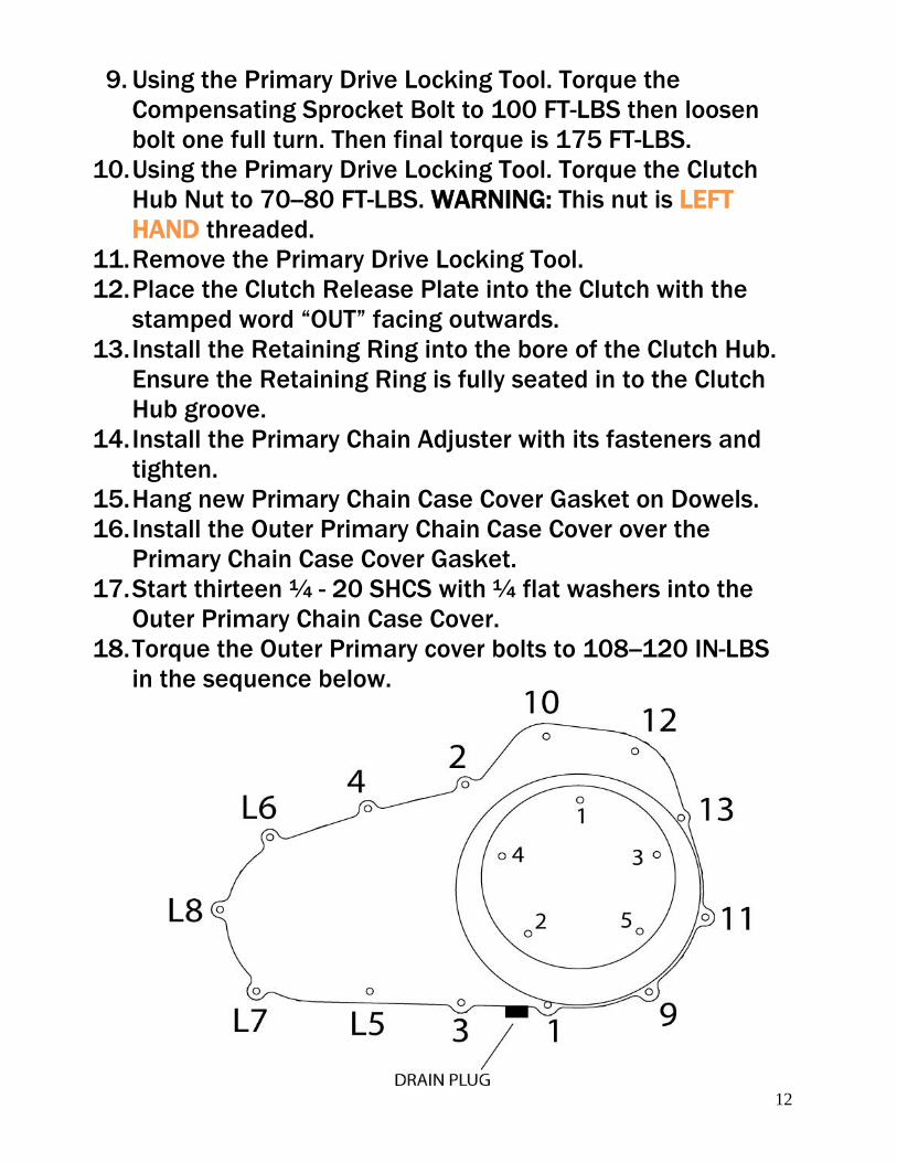
18. Torque the Outer Primary cover bolts to 108--120 IN-LBS
in the sequence below.

13
19. Apply thread sealant to the Drain Plug and reinstall.
20. Remove five ¼ - 20 torx head cap screws and the Clutch
Inspection Cover.
21. Fill the Primary Chain case with 45 oz of Primary Chain
case Lubricant.
22. Swab all lubricant from the Quad Ring groove in the
Primary Chain Case Cover. Reinstall Quad Ring.
23. Using the five ¼ - 20 torx head cap screws replace the
Clutch Inspection Cover. Torque to 84-108 IN-LBS in the
sequence above.
24. Reinstall the shift rod rubber.
25. Reinstall the Inner and Outer Shift Levers.
26. Reinstall the Front Drivers Footboard using the OEM
fasteners.
14
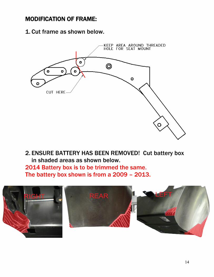
MODIFICATION OF FRAME:
1. Cut frame as shown below.
2. ENSURE BATTERY HAS BEEN REMOVED! Cut battery box
in shaded areas as shown below.
2014 Battery box is to be trimmed the same.
The battery box shown is from a 2009 – 2013.
15
Rear Suspension Unit Installation:
1. Install the Seat mount using two 5/16 – 18 x 1 HHCS with
flat washers into the rear tapped frame bosses leave loss.
Using two 5/16 – 18 x 1 1/2 HHCS with flat washers thru
the front frame thru holes into the Seat mount, place a
flat washer and nyloc nut and tighten to spec.
2. Insert the Stud Plate into the holes of the Backrest Mount.
Place the two Retaining Washers over the studs.
3. Install two frame spacers on the inside of the upper shock
mount location.
4. Make sure that the Right Rubber Engine Mount is still in
place.
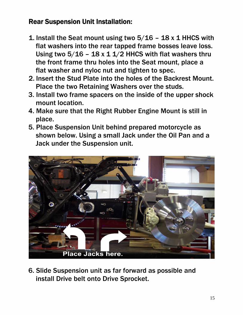
5. Place Suspension Unit behind prepared motorcycle as
shown below. Using a small Jack under the Oil Pan and a
Jack under the Suspension unit.
6. Slide Suspension unit as far forward as possible and
install Drive belt onto Drive Sprocket.
16
7. Using two 1/2 - 13 x 3 1/2 HHCS and two 1/2 flat washer
with thread locking agent. Install the Intermediate Mount
to the inside of the upper Air Shock mounting holes. Do
not tighten.
8. Raise the front Jack until the hole through the
Transmission for the Rear Fork Pivot is in the center of the
two holes for the Rear Fork Bracket.
9. Apply a light coating of Anti Seize Compound to the Rear
Fork pivot Shaft.
10. Insert the shaft from the left. The Rear Fork Pivot Shaft
will go thru the left side Drive Support Bushing,
Transmission, right side Drive Support, right side Engine
Mount, and thru the frame.
11. Loosely install the Right Rear Fork Pivot shaft Nut and
Cup Washer onto the Rear Fork Pivot Shaft. Apply thread
locking agent.
12. Install the Left Rear Fork Bracket using the OEM two 7/16
– 14 HHCS. Ensure the locating pin on the back side of
the Left Rear Fork Bracket is in the mating slot of the
Rubber Engine Mount.
13. Torque the Rear Fork Pivot Shaft Nut to 40-45 FT-LBS.
14. Remove two OEM 7/16 – 14 HHCS on the Left Rear Fork
Bracket. Install the CSC Frame Adapter with two 7/16 –
14 x 1 1/4 SHCS using thread locking agent.
Torque to 38 - 42 FT-LBS.
15. Install the Right Frame Plate by first removing the lower
rear subframe bolt, then installing the CSC Right Frame
Mount Plate.
16. Secure it with two 3/8 – 16 x 1 FHSCS in the middle two
vertical holes (depending on your desired passenger
footrest position) and one black 3/8 – 16 x 2 SHCS
threaded into the lower subframe bolt hole using thread
locking agent on all fasteners.
17
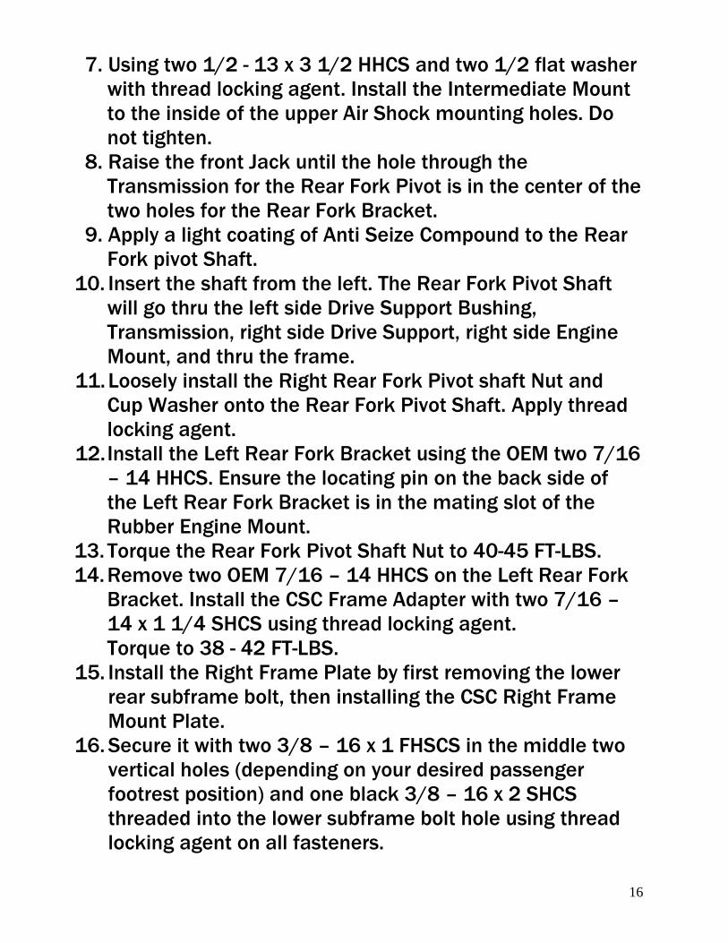
17. Install the Left Frame Mount with one 1/2 – 13 x 1 1/2
SHCS thru the Frame Adaptor threading into the forward
boss. Use thread locking agent.
18. Insert two 5/16 - 18 x 1 3/4 SHCS into the upper and
lower bosses of the Frame Mount then thru the tabs on
the Suspension unit.
19. Using two 5/16 flat washers and two 5/16 - 18 nyloc nuts
tighten the three SHCS.
20. Repeat for the Right Frame Mount.
21. Torque all fasteners left loose to spec. (shock bolts, seat
mount bolts,)
22. Tighten the four SHCS left loose by CSC to allow
suspension alignment. See RED arrows below.
18
Brake Line Installation:
1. Remove banjo bolt from OEM rear caliper. Discard rear
caliper.
2. Route the OEM rear brake hose along the frame to the
CSC distribution block.
3. Using the provided new banjo bolt and two crush
washers, install the OEM brake line onto the CSC
distribution block.
4. It may be necessary to bend the OEM hard line rearward
to gain enough length.
ABS brake equipped bikes.
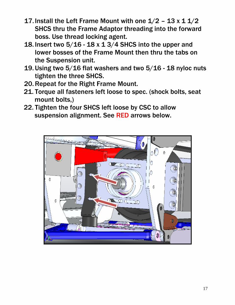
5. Route the ABS sensor wire up to the ABS control module
and plug it into the OEM wheel speed sensor plug.
6. Confirm that the air gap between the sensor and the
trigger wheel is .050 of an inch.
7. Use cable ties to hold the rear brake hose and the sensor
wire to the frame mount(s).
19
Brake bleeding procedure:
NOTE: If ABS equipped we recommend you DO NOT use a
vacuum bleeder, just hand bleed.
1. Using correct brake fluid, fill Rear Brake Master Cylinder
Reservoir.
2. Using a vacuum bleeder, follow this procedure carefully.
Rear caliper outside bleed valves first, then insides on
both sides.
3. Hand bleed the system using the above sequence. Until all
air is removed from the lines.
4. Allow the bike to set for a minimum of 20 minutes and
recheck the pedal travel.
5. If there is excessive pedal travel on the first pump, repeat
steps 3 and 4.
20
Gravel Pan:
1. Install Gravel Pan with three 1/4-20 x 3/4 HHCS four flat
washers and three nyloc nuts in the rear.
2. Install the Gravel Pan threaded Mount Plate into the
recess area under the rear of the transmission area on top
of the motorcycle frame.
If installing GRD EFX install the middle mount now. Refer to
GRD EFX installation instructions.
3. Using two 5/16-18 x 1 HHCS two flat and two lock
washers thru the Gravel pan then the frame and thread
into the Mount Plate and tighten all fasteners.
Exhaust Mount Installation:
1. Place the Left Exhaust Mount against the left side of the
Body Frame.
2. Install three 5/16 – 18 x 1 1/4 HHCS and three 5/16 flat
washers thru the Exhaust Mount and the Body Frame.
3. Install Trailer Hitch now if equipped.
4. Loosely install three 5/16 flat washers and three 5/16 –
18 nyloc nuts.
5. Install the right side with the same procedure.
21
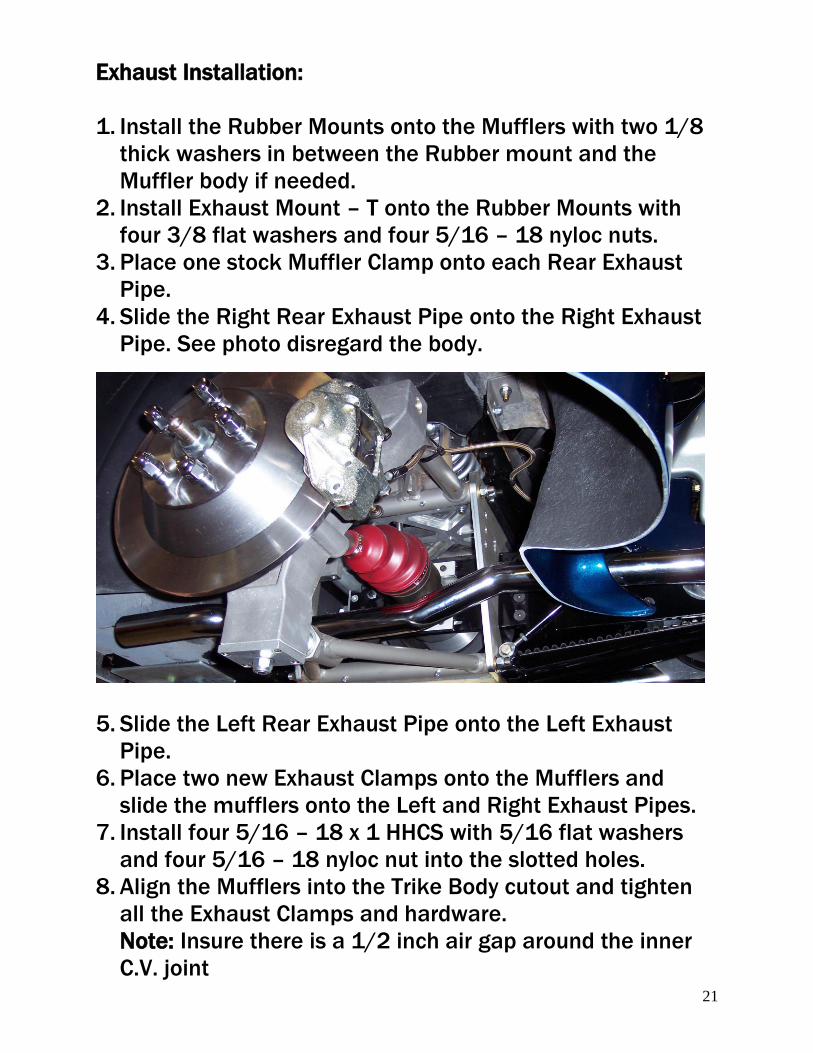
Exhaust Installation:
1. Install the Rubber Mounts onto the Mufflers with two 1/8
thick washers in between the Rubber mount and the
Muffler body if needed.
2. Install Exhaust Mount – T onto the Rubber Mounts with
four 3/8 flat washers and four 5/16 – 18 nyloc nuts.
3. Place one stock Muffler Clamp onto each Rear Exhaust
Pipe.
4. Slide the Right Rear Exhaust Pipe onto the Right Exhaust
Pipe. See photo disregard the body.
5. Slide the Left Rear Exhaust Pipe onto the Left Exhaust
Pipe.
6. Place two new Exhaust Clamps onto the Mufflers and
slide the mufflers onto the Left and Right Exhaust Pipes.
7. Install four 5/16 – 18 x 1 HHCS with 5/16 flat washers
and four 5/16 – 18 nyloc nut into the slotted holes.
8. Align the Mufflers into the Trike Body cutout and tighten
all the Exhaust Clamps and hardware.
Note: Insure there is a 1/2 inch air gap around the inner
C.V. joint
22
Link to CSC Belt Tensioning video:
http://www.californiasidecar.com/support.html
Setting up the Sonic Tension Meter:
1. Turn power on, Push Select then 1.
2. Using the charts below in Front and Rear belt tensioning
push Mass then the numbers, Width and so on.
3. For the Rear belt push Select then 2. Reverse belt can be
number 3 and so on.
Using the Sonic Tension Meter:
1. The microphone placement over the belt is critical.
a. The microphone should be in the middle of the belt
width-wise.
b. The microphone should be equally in-between the
two Sprockets.
c. The microphone should be between ¼ and ½ an inch
above or below the Belt.
2. Turn the Sonic Tension Meter on.
3. Ensure that the correct setting is displayed on the LCD
screen.
4. Push MEASURE then gently tap the Belt with a wrench
while holding the microphone in the correct position. A
measurement in Lbs. of single span tension should
display. If not continue tightening the Belt until a reading
is displayed.
5. In noisy environments the Sonic Tension Meter may
display errant numbers. If so use in a quieter area.
6. Always take at least THREE readings of the Belt tension
and average the THREE readings to determine the actual
tension of the Belt.
23
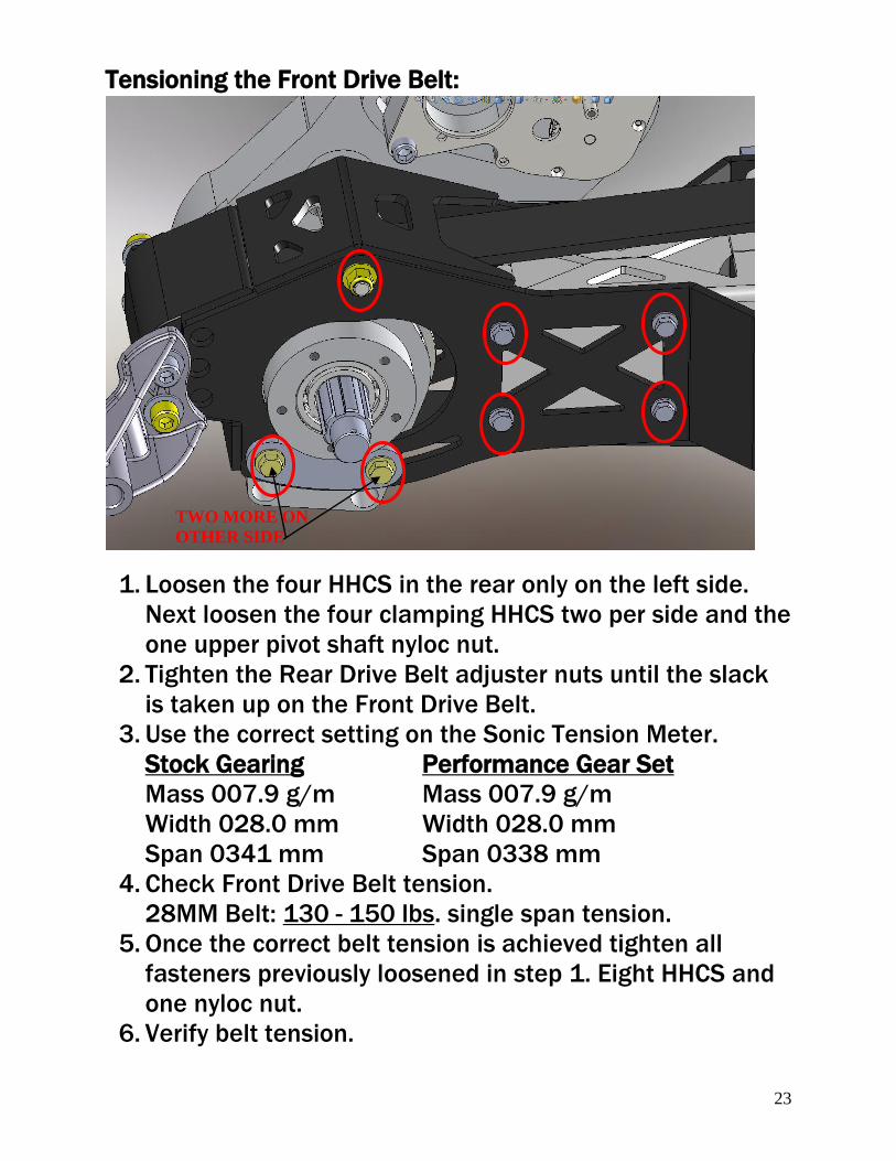
Tensioning the Front Drive Belt:
1. Loosen the four HHCS in the rear only on the left side.
Next loosen the four clamping HHCS two per side and the
one upper pivot shaft nyloc nut.
2. Tighten the Rear Drive Belt adjuster nuts until the slack
is taken up on the Front Drive Belt.
3. Use the correct setting on the Sonic Tension Meter.
Stock Gearing Performance Gear Set
Mass 007.9 g/m Mass 007.9 g/m
Width 028.0 mm Width 028.0 mm
Span 0341 mm Span 0338 mm
4. Check Front Drive Belt tension.
28MM Belt: 130 - 150 lbs. single span tension.
5. Once the correct belt tension is achieved tighten all
fasteners previously loosened in step 1. Eight HHCS and
one nyloc nut.
6. Verify belt tension.
TWO MORE ON
OTHER SIDE
24
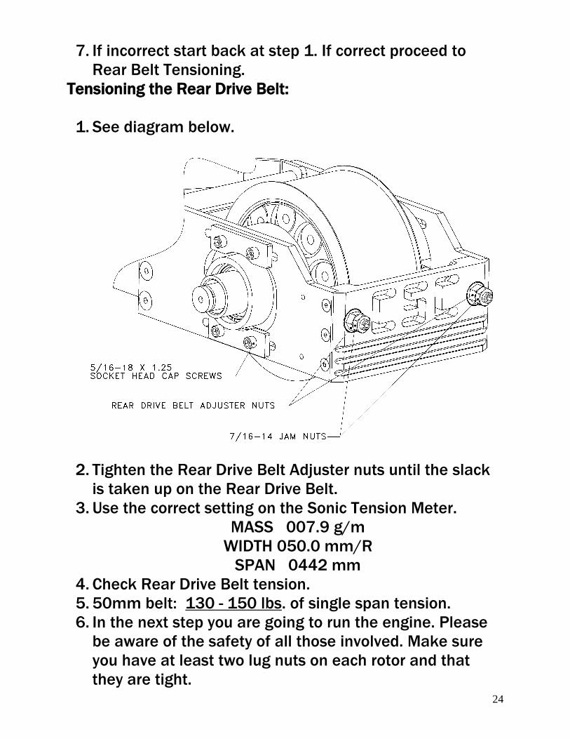
7. If incorrect start back at step 1. If correct proceed to
Rear Belt Tensioning.
Tensioning the Rear Drive Belt:
1. See diagram below.
2. Tighten the Rear Drive Belt Adjuster nuts until the slack
is taken up on the Rear Drive Belt.
3. Use the correct setting on the Sonic Tension Meter.
MASS 007.9 g/m
WIDTH 050.0 mm/R
SPAN 0442 mm
4. Check Rear Drive Belt tension.
5. 50mm belt: 130 - 150 lbs. of single span tension.
6. In the next step you are going to run the engine. Please
be aware of the safety of all those involved. Make sure
you have at least two lug nuts on each rotor and that
they are tight.
25
7. To finish alignment, the belt must have at least 0.040in
clearance between edge of belt and fence on front Rear
Drive Sprocket. Check this by starting the engine and
placing it in second gear and simply let the engine idle.
Checking the alignment by eye and centering the belt as
it spins. If belt has correct clearance, go to step 9. If it
does not have clearance, proceed to step 8.
8. Use the Left and Right Rear Drive Belt Adjuster Nuts to
align belt in order to achieve the necessary belt
clearance. NOTE: The belt will always track to the side of
the sprocket that is the loosest. Repeat step 4.
9. Once the correct belt alignment and single span tension
is achieved, tighten the eight 5/16 – 18 x 1 ¼ SHCS that
go into the Carrier Bearing Support Housings.
10. Install two 7/16 – 14 hex jam nuts onto the Rear Drive
Belt Tensioning Studs and tighten.
11. Verify belt tension and alignment.
12. If all is correct move on to next step. If not loosen
clamping bolts and return to step 4.
Service Limits on Drive Belts:
Service limit on the Front Drive Belt is 130 - 150 lbs.
Service limit on the Rear Drive Belt is 130 - 150 lbs.
26
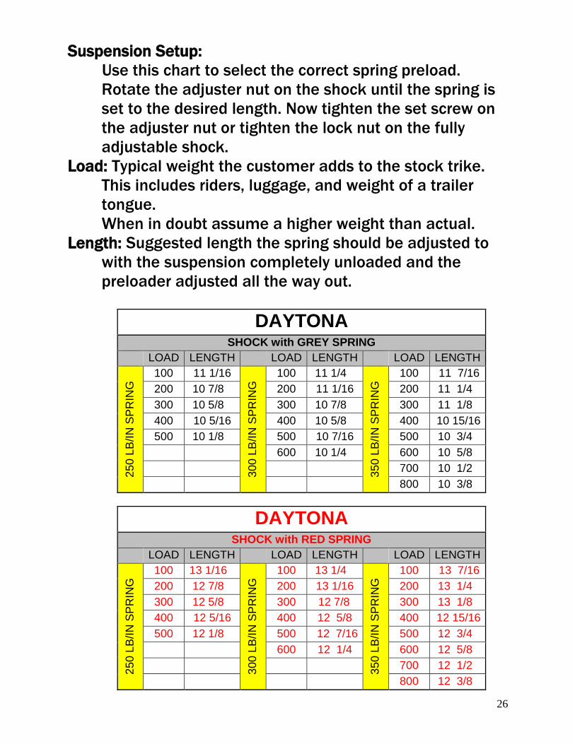
Suspension Setup:
Use this chart to select the correct spring preload.
Rotate the adjuster nut on the shock until the spring is
set to the desired length. Now tighten the set screw on
the adjuster nut or tighten the lock nut on the fully
adjustable shock.
Load: Typical weight the customer adds to the stock trike.
This includes riders, luggage, and weight of a trailer
tongue.
When in doubt assume a higher weight than actual.
Length: Suggested length the spring should be adjusted to
with the suspension completely unloaded and the
preloader adjusted all the way out.
DAYTONA
SHOCK with GREY SPRING
LOAD LENGTH LOAD LENGTH LOAD LENGTH
25
0 L
B/I
N S
PR
ING
100 11 1/16
30
0 L
B/I
N S
PR
ING
100 11 1/4 3
50
LB
/IN
SP
RIN
G 100 11 7/16
200 10 7/8 200 11 1/16 200 11 1/4
300 10 5/8 300 10 7/8 300 11 1/8
400 10 5/16 400 10 5/8 400 10 15/16
500 10 1/8 500 10 7/16 500 10 3/4
600 10 1/4 600 10 5/8
700 10 1/2
800 10 3/8
DAYTONA
SHOCK with RED SPRING
LOAD LENGTH LOAD LENGTH LOAD LENGTH
25
0 L
B/I
N S
PR
ING
100 13 1/16
30
0 L
B/I
N S
PR
ING
100 13 1/4
35
0 L
B/I
N S
PR
ING
100 13 7/16
200 12 7/8 200 13 1/16 200 13 1/4
300 12 5/8 300 12 7/8 300 13 1/8
400 12 5/16 400 12 5/8 400 12 15/16
500 12 1/8 500 12 7/16 500 12 3/4
600 12 1/4 600 12 5/8
700 12 1/2
800 12 3/8
27
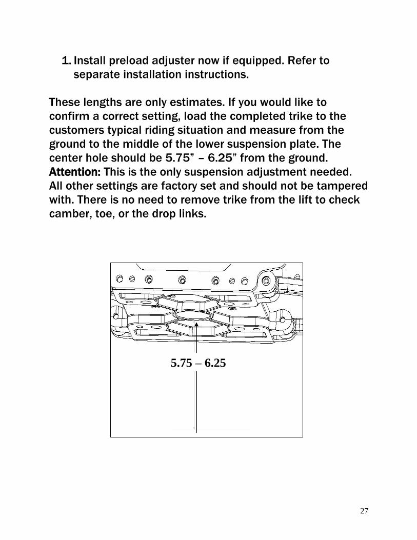
1. Install preload adjuster now if equipped. Refer to
separate installation instructions.
These lengths are only estimates. If you would like to
confirm a correct setting, load the completed trike to the
customers typical riding situation and measure from the
ground to the middle of the lower suspension plate. The
center hole should be 5.75” – 6.25” from the ground.
Attention: This is the only suspension adjustment needed.
All other settings are factory set and should not be tampered
with. There is no need to remove trike from the lift to check
camber, toe, or the drop links.
5.75 – 6.25
28
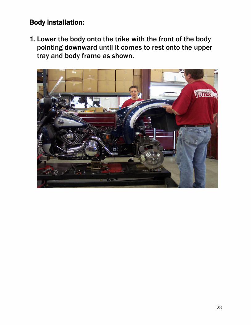
Body installation:
1. Lower the body onto the trike with the front of the body
pointing downward until it comes to rest onto the upper
tray and body frame as shown.
29
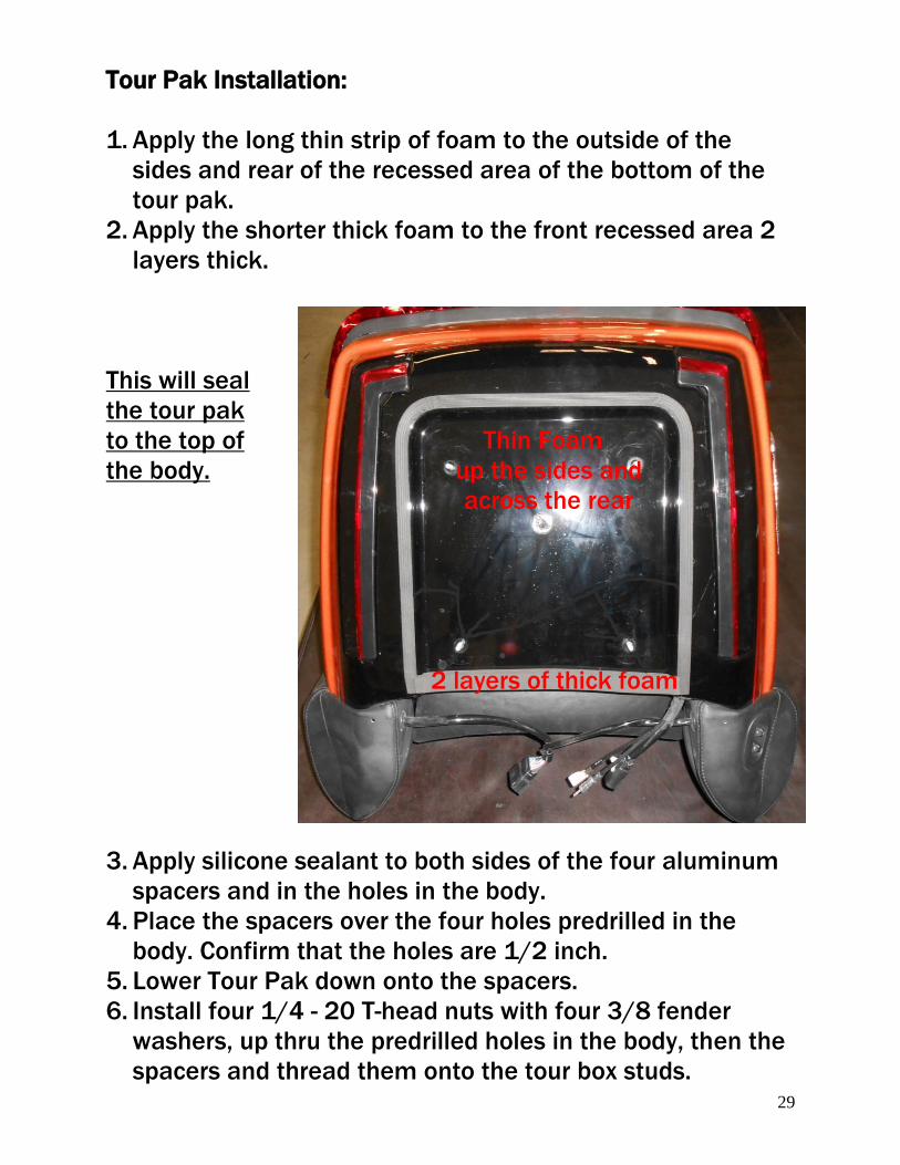
Tour Pak Installation:
1. Apply the long thin strip of foam to the outside of the
sides and rear of the recessed area of the bottom of the
tour pak.
2. Apply the shorter thick foam to the front recessed area 2
layers thick.
This will seal
the tour pak
to the top of Thin Foam
the body. up the sides and
across the rear
2 layers of thick foam
3. Apply silicone sealant to both sides of the four aluminum
spacers and in the holes in the body.
4. Place the spacers over the four holes predrilled in the
body. Confirm that the holes are 1/2 inch.
5. Lower Tour Pak down onto the spacers.
6. Install four 1/4 - 20 T-head nuts with four 3/8 fender
washers, up thru the predrilled holes in the body, then the
spacers and thread them onto the tour box studs.
30
Trike body alignment:
1. Route the Trunk Emergency Release cable along the right
side of the Frame and tie just behind the Right Side Cover.
2. If installing Ground Effects see separate instruction.
3. Connect Body Wiring Harness connector under the Frame
to the Rear Fender Wiring Harness Connector. Plug in the
adaptor between the CSC body plug and the 2014 H-D
fender plug.
4. Route the Fuse-able Link and the White Wire towards the
Battery.
5. Locate the 2 pin plug at the fender plug location and route
that 2 wire harness forward to the BCM.
6. Connect the Red wire to the Right Front turn signal wire,
(Blue/Orange) at the BCM.
7. Connect the Black wire to the Left Front turn signal wire,
(Blue/Pink) 2014-2016, (Blue/Black) 2017-up at the
BCM. These wires are right next to each other.
8. Install the Right and Left Side Covers.
9. The Trike Body can move left, right, forward, backward,
up, down, and angled. Shimming with the provided 1/4
and 1/8 Rubber Washers may be required to get the Trike
Body into alignment.
10. First raise the front of the body to obtain the vertical
location around the Side Covers.
11. Then slide the body front to back to get the horizontal
location around the Side Covers.
12. With the body temporarily held into place, raise the
adjustable 90° body support brackets until they seat
against the body’s inner liner.
13. Tighten the two 5/16 – 18 x ¾ HHCS and two 5/16 – 18
nyloc nuts on the Adjustable 90° Support Brackets.
31
14. Center the Trike Body left to right with the Trailer hitch (if
equipped) and Side Covers.
Securing the Trike body:
1. Using a 5/16 twist drill, drill up through the Adjustable
90° Body Support Brackets.
Note: A small section of Trike Body Carpet has not been
glued at the location of the Trike Body Frame mounting
tabs to allow removal of the bolts used in shipping, and
installation of the Trike Body mounting hardware. The
predrilled bolt holes may need to be enlarged or relocated
for Trike Body attachment to the Trike Body Frame
mounting tabs. If relocation is necessary, the
preexisting holes will need to be sealed with silicone
sealant.
2. Using a 5/16 twist drill, drill up through the Trike Body
Frame mounting tabs.
3. Insert two 5/16 – 18 x 1 ¼ HHCS, two 5/16 x 1 ½ fender
washers, and rubber washers if necessary through the
holes drilled in step 2.
4. Insert two 5/16 – 18 x 1 ¼ HHCS and two 5/16 x 1 ½
fender washers through the adjustable 90° body support
brackets.
5. Install four 5/16–18 nyloc nuts and four 5/16 flat
washers onto the four 5/16–18 x 1 ¼ HHCS and tighten.
32
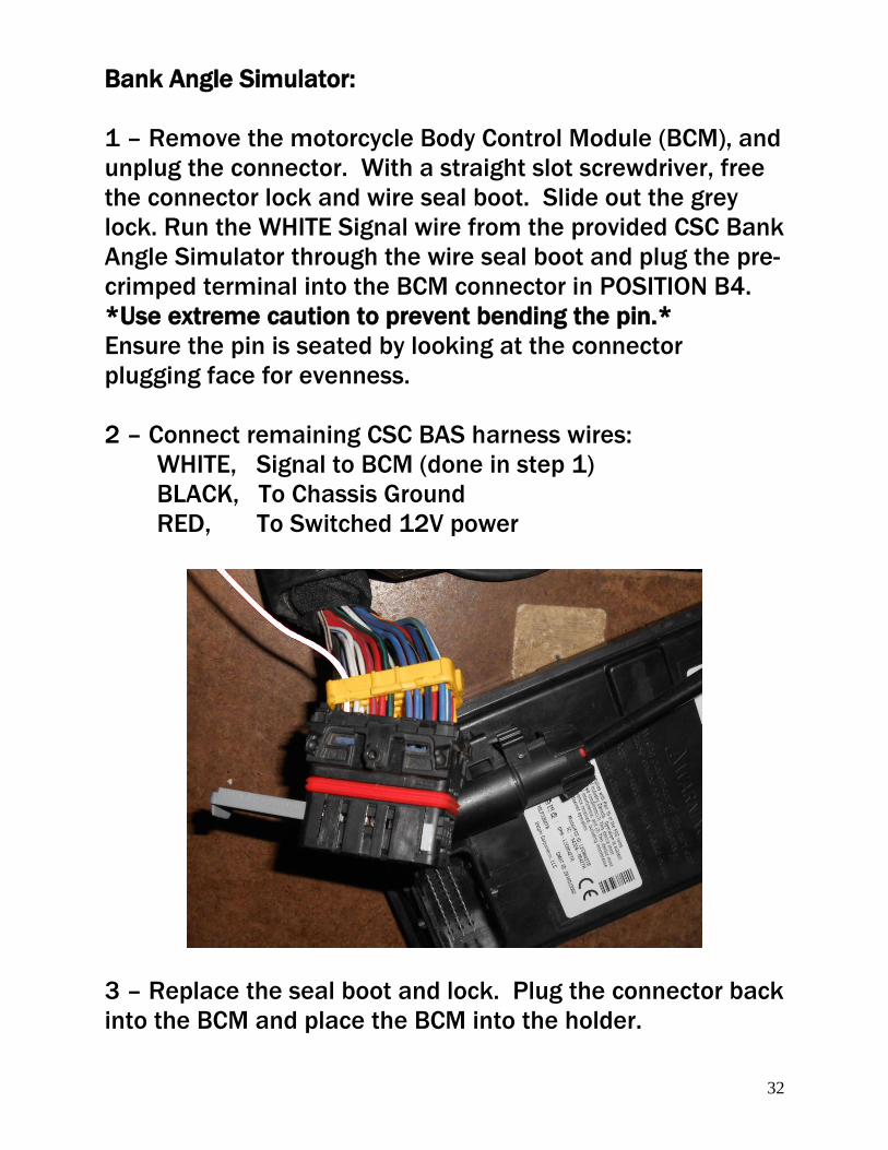
Bank Angle Simulator:
1 – Remove the motorcycle Body Control Module (BCM), and
unplug the connector. With a straight slot screwdriver, free
the connector lock and wire seal boot. Slide out the grey
lock. Run the WHITE Signal wire from the provided CSC Bank
Angle Simulator through the wire seal boot and plug the pre-
crimped terminal into the BCM connector in POSITION B4.
*Use extreme caution to prevent bending the pin.*
Ensure the pin is seated by looking at the connector
plugging face for evenness.
2 – Connect remaining CSC BAS harness wires:
WHITE, Signal to BCM (done in step 1)
BLACK, To Chassis Ground
RED, To Switched 12V power
3 – Replace the seal boot and lock. Plug the connector back
into the BCM and place the BCM into the holder.
33
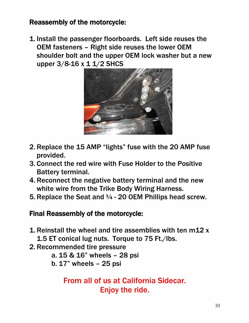
Reassembly of the motorcycle:
1. Install the passenger floorboards. Left side reuses the
OEM fasteners – Right side reuses the lower OEM
shoulder bolt and the upper OEM lock washer but a new
upper 3/8-16 x 1 1/2 SHCS
2. Replace the 15 AMP “lights” fuse with the 20 AMP fuse
provided.
3. Connect the red wire with Fuse Holder to the Positive
Battery terminal.
4. Reconnect the negative battery terminal and the new
white wire from the Trike Body Wiring Harness.
5. Replace the Seat and ¼ - 20 OEM Phillips head screw.
Final Reassembly of the motorcycle:
1. Reinstall the wheel and tire assemblies with ten m12 x
1.5 ET conical lug nuts. Torque to 75 Ft./lbs.
2. Recommended tire pressure
a. 15 & 16” wheels – 28 psi
b. 17” wheels – 25 psi
From all of us at California Sidecar.
Enjoy the ride.


![Easy Lifter RDO Manual[1]](https://img.pdfslide.us/doc/110x75/5477fc1eb4af9f87108b4b04/easy-lifter-rdo-manual1.jpg)
