Embed Size (px)
Citation preview
Camera Calibration
Calibration Points Marking
21
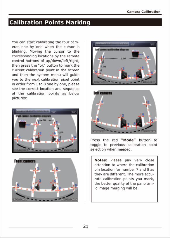
You can start calibrating the four cam-eras one by one when the cursor is blinking. Moving the cursor to the corresponding locations by the remote control buttons of up/down/left/right, then press the “ok” button to mark the current calibration point in the screen and then the system menu will guide you to the next calibration pixel point in order from 1 to 8 one by one, please see the correct location and sequence of the calibration points as below pictures:
Press the red “Mode” button to toggle to previous calibration point selection when needed.
Notes: Please pay very close attention to where the calibration pin location for number 7 and 8 as they are different. The more accu-rate calibration points you mark, the better quality of the panoram-ic image merging will be.
Camera Calibration
Camera Calibration
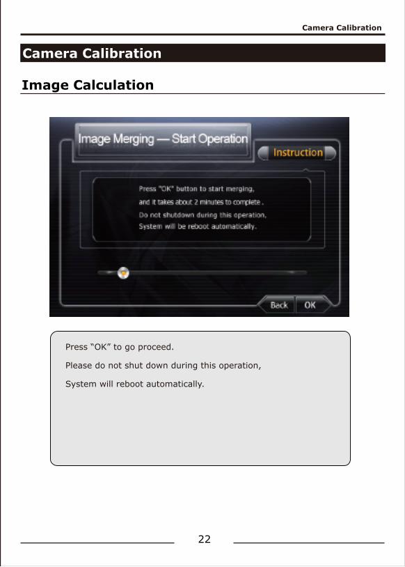
Image Calculation
22
Press “OK” to go proceed.
Please do not shut down during this operation,
System will reboot automatically.
User Settings
User Settings
23
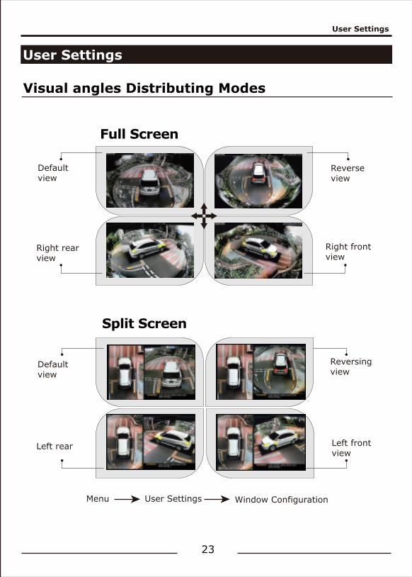
Visual angles Distributing Modes
Full Screen
Split Screen
Default view
Reverse view
Menu User Settings Window Configuration
Right rear view
Right front view
Default view
Reversing view
Left rear Left front view
User Settings
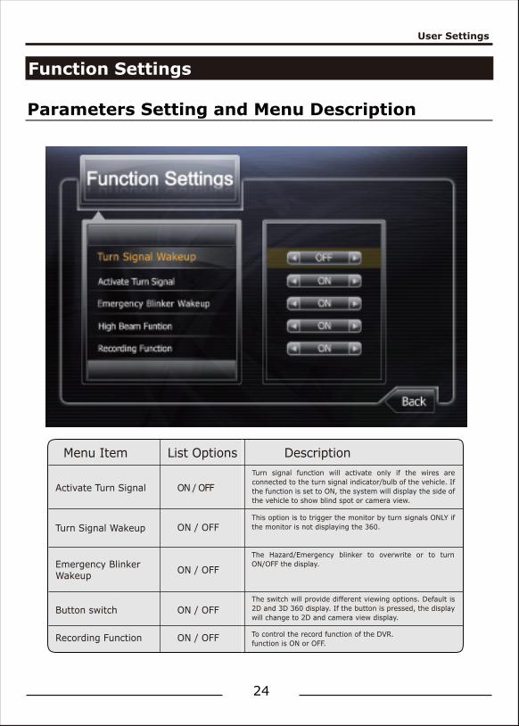
Function Settings
Parameters Setting and Menu Description
24
Menu Item
Activate Turn Signal
Turn Signal Wakeup
Emergency BlinkerWakeup
Button switch
Recording Function
ON / OFF
ON / OFF
ON / OFF
ON / OFF
ON / OFF
List Options DescriptionTurn signal function will activate only if the wires are connected to the turn signal indicator/bulb of the vehicle. If the function is set to ON, the system will display the side of the vehicle to show blind spot or camera view.
The Hazard/Emergency blinker to overwrite or to turn ON/OFF the display.
The switch will provide different viewing options. Default is 2D and 3D 360 display. If the button is pressed, the display will change to 2D and camera view display.
To control the record function of the DVR.function is ON or OFF.
This option is to trigger the monitor by turn signals ONLY if the monitor is not displaying the 360.
User Settings
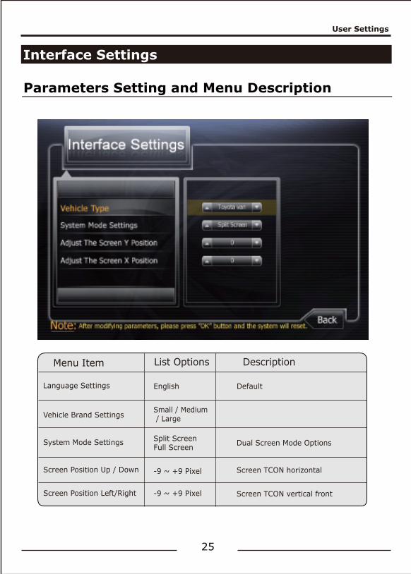
Interface Settings
25
Parameters Setting and Menu Description
Menu Item
Language Settings
Vehicle Brand Settings
System Mode Settings
Screen Position Up / Down
Screen Position Left/Right
English
Small / Medium / Large
Default
Split ScreenFull Screen
-9 ~ +9 Pixel
-9 ~ +9 Pixel
List Options Description
Dual Screen Mode Options
Screen TCON horizontal
Screen TCON vertical front
User Settings
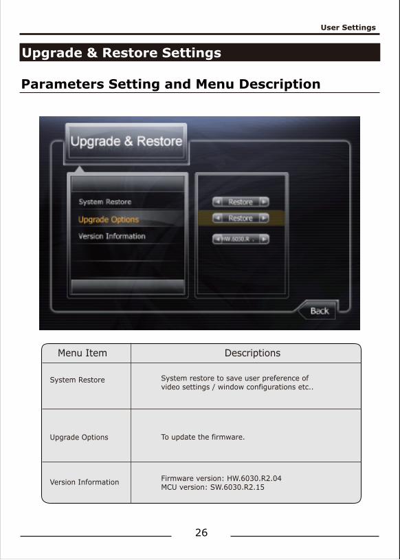
Upgrade & Restore Settings
Parameters Setting and Menu Description
26
Menu Item
System Restore
Upgrade Options
Version Information
Descriptions
System restore to save user preference of video settings / window configurations etc..
To update the firmware.
Firmware version: HW.6030.R2.04MCU version: SW.6030.R2.15
User Settings
Other Settings
27
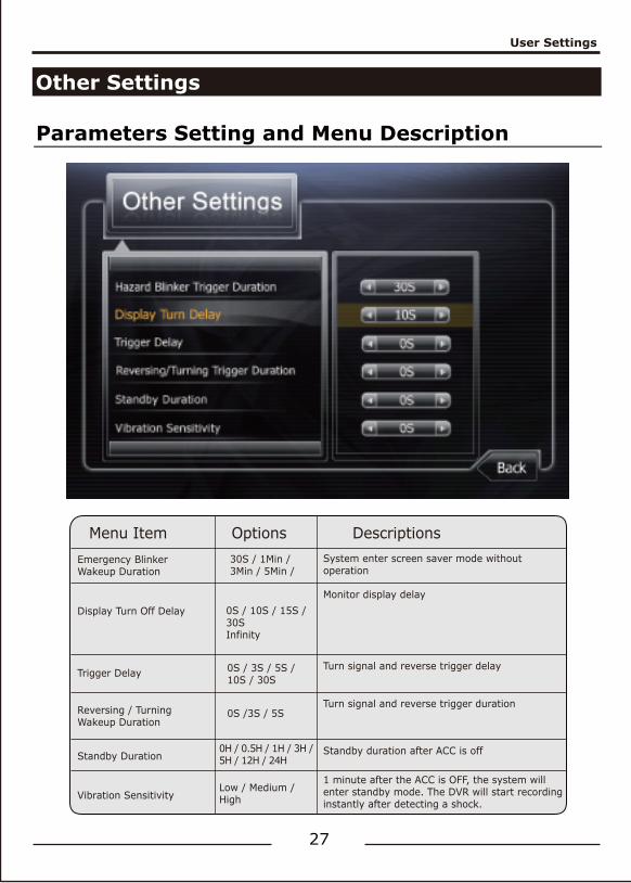
Parameters Setting and Menu Description
Menu ItemEmergency Blinker Wakeup Duration
Display Turn Off Delay
Reversing / TurningWakeup Duration
Trigger Delay
Standby Duration
Options DescriptionsSystem enter screen saver mode without operation
Monitor display delay
Turn signal and reverse trigger duration
Turn signal and reverse trigger delay
Standby duration after ACC is off
0S / 10S / 15S / 30SInfinity
0H / 0.5H / 1H / 3H /5H / 12H / 24H
Vibration Sensitivity1 minute after the ACC is OFF, the system will enter standby mode. The DVR will start recording instantly after detecting a shock.
Low / Medium / High
30S / 1Min / 3Min / 5Min /
0S / 3S / 5S /10S / 30S
0S /3S / 5S
User Settings
Video Settings
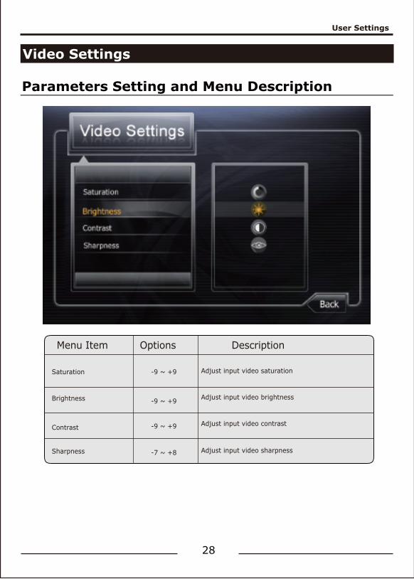
Parameters Setting and Menu Description
28
Menu Item
Saturation
Brightness
Contrast
Sharpness
-9 ~ +9
-9 ~ +9
-9 ~ +9
-7 ~ +8
Options Description
Adjust input video saturation
Adjust input video contrast
Adjust input video sharpness
Adjust input video brightness
User Settings
User Settings
29
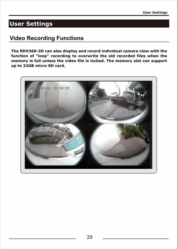
Video Recording Functions
The RDV360-3D can also display and record individual camera view with the function of "loop" recording to overwrite the old recorded files when the memory is full unless the video file is locked. The memory slot can support up to 32GB micro SD card.
Recording Parameters
Recording Parameters
Basic Settings
30
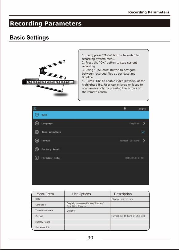
1. Long press “Mode” button to switch to recording system menu.2. Press the “OK” button to stop current recording.3. Using “Up/Down” button to navigate between recorded files as per date and timeline.4. Press "OK" to enable video playback of the highlighted file. User can enlarge or focus to one camera only by pressing the arrows on the remote control.
Menu ItemDate
Language
Time Watermark
Format
Factory Reset
Firmware Info
Change system time
Format the TF Card or USB Disk
English/Japanese/Korean/Russian/Simplified Chinese
ON/OFF
List Options Description
Smart Power Management Strategy
Smart Power Management Strategy
31
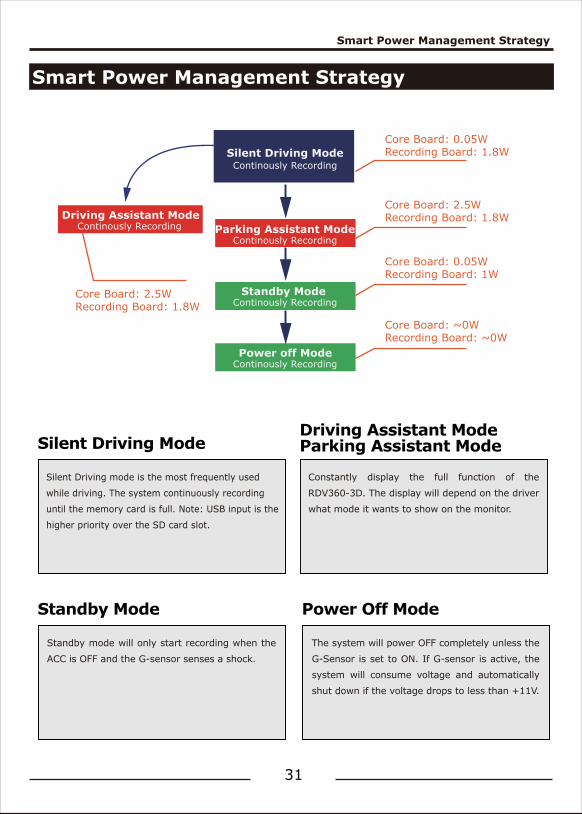
Silent Driving Mode
Silent Driving mode is the most frequently used
while driving. The system continuously recording
until the memory card is full. Note: USB input is the
higher priority over the SD card slot.
Standby Mode
Standby mode will only start recording when the
ACC is OFF and the G-sensor senses a shock.
Power Off Mode
The system will power OFF completely unless the
G-Sensor is set to ON. If G-sensor is active, the
system will consume voltage and automatically
shut down if the voltage drops to less than +11V.
Driving Assistant ModeParking Assistant Mode
Constantly display the full function of the
RDV360-3D. The display will depend on the driver
what mode it wants to show on the monitor.
Silent Driving ModeContinously Recording
Parking Assistant ModeContinously Recording
Driving Assistant ModeContinously Recording
Standby ModeContinously Recording
Power off ModeContinously Recording
Core Board: 0.05WRecording Board: 1.8W
Core Board: 2.5WRecording Board: 1.8W
Core Board: 0.05WRecording Board: 1W
Core Board: ~0WRecording Board: ~0W
Core Board: 2.5WRecording Board: 1.8W
Troubleshooting
Troubleshooting
32
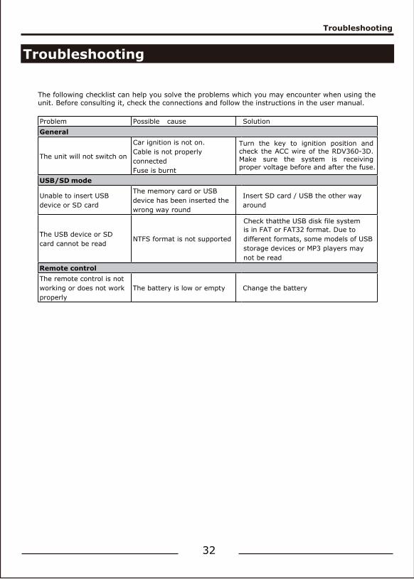
Turn the key to ignition position and check the ACC wire of the RDV360-3D. Make sure the system is receiving proper voltage before and after the fuse.
The following checklist can help you solve the problems which you may encounter when using the unit. Before consulting it, check the connections and follow the instructions in the user manual.
Problem Possible cause SolutionGeneral
The unit will not switch on
Car ignition is not on.Cable is not properly connectedFuse is burnt
USB/SD mode
Unable to insert USB device or SD card
The memory card or USB device has been inserted the wrong way round
Insert SD card / USB the other way around
The USB device or SD card cannot be read
NTFS format is not supported
is in FAT or FAT32 format. Due to different formats, some models of USB storage devices or MP3 players may not be read
Remote controlThe remote control is not working or does not work properly
The battery is low or empty Change the battery
Check thatthe USB disk file system
Smart Power Management Strategy
One Year Limited Warranty
33
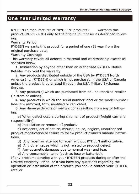
RYDEEN (a manufacturer of “RYDEEN" products) warrants this product (RDV360-3D) only to the original purchaser as described follow-ing:Warranty PeriodRYDEEN warrants this product for a period of one (1) year from the original purchase date.Warranty CoverageThis warranty covers all defects in material and workmanship except as specified below. 1. Installation by anyone other than an authorized RYDEEN Mobile Retailer may void the warranty. 2. Any products distributed outside of the USA by RYDEEN North America Inc. (RYDEEN) or which is not purchased in the USA or Canada unless the product is purchased through the USA Military Exchange Service. 3. Any product(s) which are purchased from an unauthorized retailer (in store or online). 4. Any products in which the serial number label or the model number label are removed, torn, modified or replicated. 5. Any damage defects or malfunctions resulting from any of follow-ing: a) When defect occurs during shipment of product (freight carrier's responsibility). b) Installation or removal of product. c) Accidents, act of nature, misuse, abuse, neglect, unauthorized product modification or failure to follow product owner's manual instruc-tions. d) Any repair or attempt to repair without RYDEEN authorization. e) Any other cause which is not related to product defect. f) Any cosmetic damages due to normal wear and tear. g) Any consumable items (such as fuse or batteries).If any problems develop with your RYDEEN products during or after the Limited Warranty Period, or if you have any questions regarding the operation or installation of the product, you should contact your RYDEEN retailer.
To Obtain Warranty Service
To Obtain Warranty Service
34
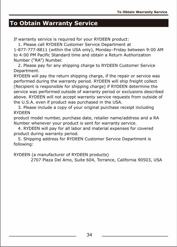
If warranty service is required for your RYDEEN product: 1. Please call RYDEEN Customer Service Department at 1-877-777-8811 (within the USA only), Monday–Friday between 9:00 AM to 4:00 PM Pacific Standard time and obtain a Return Authorization Number (“RA”) Number. 2. Please pay for any shipping charge to RYDEEN Customer Service Department.RYDEEN will pay the return shipping charge, if the repair or service was performed during the warranty period. RYDEEN will ship freight collect(Recipient is responsible for shipping charge) if RYDEEN determine the service was performed outside of warranty period or exclusions described above. RYDEEN will not accept warranty service requests from outside of the U.S.A. even if product was purchased in the USA. 3. Please include a copy of your original purchase receipt including RYDEENproduct model number, purchase date, retailer name/address and a RA Number whenever your product is sent for warranty service. 4. RYDEEN will pay for all labor and material expenses for covered product during warranty period. 5. Shipping address for RYDEEN Customer Service Department is following: RYDEEN (a manufacturer of RYDEEN products) 2707 Plaza Del Amo, Suite 604, Torrance, California 90503, USA
Smart Power Management Strategy
FCC Compliance Statement
CE Compliance Statement
Disclaimer
35
This device complies with Part 15 of the FCC interference limits for Class B digital devices for home or office use. These limits are designed to provide more reasonable protection against harmful interference in a residential installation and are more stringent than “outdoor” requirements. Operation of this device is subject to the following conditions:1. This device may not cause harmful interference, and 2. This device must accept any interference received, including interference that may cause
undesired operation.
Operation of this device is subject to the following conditions:1. This device may not cause harmful interference, and 2. This device must accept any interference received, including interference that may cause
undesired operation.
The information in this user manual is for general guidance. Images in the manual may not represent the exact images that are displayed in the operating system software. Some features described in the manual may not be available or the features described may be limited, depending on the updated software or any other reasons.
This device described above has been tested, and the test results show that the equipment under test (EUT) is in compliance with the 2014/30/EU requirements. And it is applicable only to the tested sample identified in the report.