Embed Size (px)
Citation preview
CHECK THE MASTER LIST—VERIFY THAT THIS IS THE CORRECT VERSION BEFORE USE
MSFC - Form 454 (Rev. October 1992)
GBM-PLAN-1016National Aeronautics and DRAFTSpace Administration EFFECTIVE DATE: 8 June 2004
George C. Marshall Space Flight CenterMarshall Space Flight Center, Alabama 35812
SD50
GLAST BURST MONITOR
Calibration Plan for the GBM
DRAFT, Prior to Baseline
GBM-Plan-1014 Baseline
CHECK THE MASTER LIST VERIFY THAT THIS IS THE CORRECT VERSION BEFORE USEPage 2
GLAST Burst Monitor(GBM)
Calibration Plan
_______________________________________ ___________________Prepared by DateJerry FishmanCo-Investigator, GBM andGiselher LichtiCo-Principal Investigator, GBM
_______________________________________ ___________________Approved by DateStephen E. ElrodGBM Project Manager
_______________________________________ ___________________Approved by DateCharles A. MeeganGBM Principal Investigator

GBM-Plan-1014 Baseline
CHECK THE MASTER LIST VERIFY THAT THIS IS THE CORRECT VERSION BEFORE USEPage 3
MSFC Form 4140 (Rev. September 1990) NOTE: After revising the document, file this sheet in document preceding Table of Contents. Informed 2.6.3
Release Date:
06 / 09/ 2004
Marshall Space Flight CenterSPECIFICATION/DOCUMENT
CHANGE INSTRUCTIONPage 1 of 1
Specification/Doc. No.:GBM-PLAN-1016
Copy No.
Change
No./Date
SCN/DCNNo./Date
CCBDNo./Date
Replacement PageInstructions
06/09/04 Baseline Release
GBM-Plan-1014 Baseline
CHECK THE MASTER LIST VERIFY THAT THIS IS THE CORRECT VERSION BEFORE USEPage 4
Acronyms and Abbreviations
BGO Bismuth Germanatecm centimeterscps counts per secondFWHM Full-width half-maximumGBM GLAST Burst MonitorGEANT Geometry and Tracking Monte-Carlo ProgramGLAST Gamma Ray Large Area Space TelescopeGRB Gamma-Ray BurstHV High VoltageHVPS High Voltage Power SupplyHWHM Half-width half-maximumI&T Integration and Testkcps kilo counts per secondNaI Sodium Iodide
GBM-Plan-1014 Baseline
CHECK THE MASTER LIST VERIFY THAT THIS IS THE CORRECT VERSION BEFORE USEPage 5
1. PURPOSE
The calibrations and tests in this GLAST Burst Monitor (GBM) Calibration Plan servethree purposes:
I. To provide performance verification of distinct elements of the GBMdetector system, including the flight data system. These verificationelements are described in the GBM Verification Plan, GBM-PLAN-1014.
II. To provides calibration data that will be used for orbital operations andin data analysis in order to ensure efficient operation of the flightsystem and accurate, well-characterized data for subsequent scientificanalysis.
III. To provide benchmark data to compare with calculated detectorresponse data which cannot be derived from actual calibration data dueto limited resources, schedule, or other physical limitations
This Plan defines the test procedures and identifies the organizations responsible forconducting these calibrations. It includes a summary of each calibration and identifiesthe person responsible for writing the procedure and the due date for the completedprocedure.
These calibrations will be performed on GBM flight detector hardware. It is suggestedthat procedures for these tests be performed on GBM science model detectors severalmonths before their actual use on flight detectors, in order to streamline the testprocedures and avoid schedule delays.
Acceptance tests are intended to verify that the hardware design meets requirements.Functional tests are generally performed numerous times and verify that the flighthardware still performs properly.
2. APPLICABILITY
Verification is in accordance with Marshall Work Instruction 8050.1 within the scope ofMPD 1280.1, “Marshall Management Manual” (MMM). This plan will apply to theGLAST Burst Monitor test program and verification for the entire instrument.
3. APPLICABLE DOCUMENTS
3.1 MPD 1280.1, “Marshall Management Manual”3.2 MPG 8060.1, “Flight Systems Design/Development Control”3.3 MPG 8040.1, “Configuration Management, MSFC Programs/Projects”
GBM-Plan-1014 Baseline
CHECK THE MASTER LIST VERIFY THAT THIS IS THE CORRECT VERSION BEFORE USEPage 6
3.4 MWI 7120.2, “Data Requirements Identification/Definition”3.5 MPG 8730.1, “Inspection and Testing”3.6 MPG 8730.3, “Control of Nonconforming Product”3.7 MPG 1280.4, “MSFC Corrective Action System”3.8 MPG 1440.2, “MSFC Records Management Program”
4. REFERENCES
Schötzig, Ulrich and Heinrich Schrader: Physikalisch-Technische Bundesanstalt PTB-Ra-16/5, Braunschweig, September 1998
5. DEFINITIONS
None
6. INSTRUCTIONS
The Principal Investigator, or his designee, has overall responsibility for developing andimplementing a Calibration Plan that will be the basis for verification, tests andcalibration of detectors and detector systems for the flight mission. The paragraphs thatfollow identify activities needed to be performed, either sequentially or concurrently, thatwill ensure proper calibration of the flight detector system.
7. NOTES - Test Numbering Scheme
GBM-PROC-TP0XX Miscellaneous tests (a catch-all for tests that defy classification)GBM-PROC-TP1XX Detector development tests at MPE (possibly repeated at MSFC)
& calibrationsGBM-PROC-TP5XX Subsystem hardware tests at MSFC
(also includes subsystem bench testing at S/C I&T)GBM-PROC-TP6XX System level hardware tests at MSFC, including thermal-vacGBM-PROC-TP8XX Tests during S/C I&T, including ETE testsGBM-PROC-TP9XX On-orbit tests
8. SAFETY PRECAUTIONS AND WARNING NOTES
As specified in the individual procedures. Many of these tests and calibrations requirethe use of radioactive sources. The handling, use and storage of these sources are subjectto federal and state regulations.
GBM-Plan-1014 Baseline
CHECK THE MASTER LIST VERIFY THAT THIS IS THE CORRECT VERSION BEFORE USEPage 7
9. RECORDS
The Project Manager shall be responsible for maintaining and archiving the followingverification-related documentation as Quality Records in accordance with MPG 1440.2.
Verification program documentation will be recorded by reference in the GBMRequirements Database (GBM-REQ-1007). All verification data will be stored in filesmaintained by the GBM Lead Systems Engineer. The files will be stored in the foldersindexed to the GBM Requirements Database in the verification section for eachrequirement.
Compliance Data, including nonconformances, waivers, and deviations will also berecorded by reference in the GBM Requirements Database (GBM-REQ-1007). The fileswill be stored in the folders indexed to the GBM Requirements Database in thecompliance section for each requirement. All non conformances will be noted byrequirement in the database and hardcopies will be stored with the verification andcompliance data.
10. PERSONNEL TRAINING AND CERTIFICATION
The calibration test conductor for each test will be assigned by the Principal Investigator,the Co-Principal Investigator, or the Lead Systems Engineer.
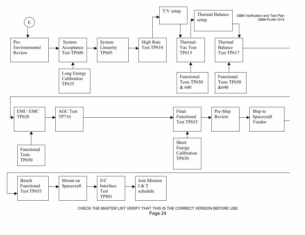
11. FLOW DIAGRAM
The flight hardware and test flow diagram is contained in the GBM Verification Plan#1014. A version is also attached herein for convenience, however the reader should notethat this may not be a current version.
12. CANCELLATION
None
GBM-Plan-1014 Baseline
CHECK THE MASTER LIST VERIFY THAT THIS IS THE CORRECT VERSION BEFORE USEPage 8
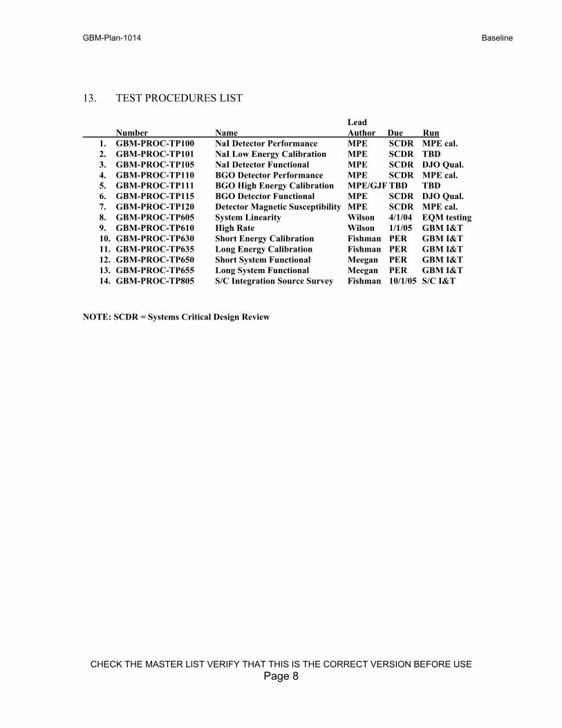
13. TEST PROCEDURES LIST
Lead Number Name Author Due Run
1. GBM-PROC-TP100 NaI Detector Performance MPE SCDR MPE cal.2. GBM-PROC-TP101 NaI Low Energy Calibration MPE SCDR TBD3. GBM-PROC-TP105 NaI Detector Functional MPE SCDR DJO Qual.4. GBM-PROC-TP110 BGO Detector Performance MPE SCDR MPE cal.5. GBM-PROC-TP111 BGO High Energy Calibration MPE/GJF TBD TBD6. GBM-PROC-TP115 BGO Detector Functional MPE SCDR DJO Qual.7. GBM-PROC-TP120 Detector Magnetic Susceptibility MPE SCDR MPE cal.8. GBM-PROC-TP605 System Linearity Wilson 4/1/04 EQM testing9. GBM-PROC-TP610 High Rate Wilson 1/1/05 GBM I&T10. GBM-PROC-TP630 Short Energy Calibration Fishman PER GBM I&T11. GBM-PROC-TP635 Long Energy Calibration Fishman PER GBM I&T12. GBM-PROC-TP650 Short System Functional Meegan PER GBM I&T13. GBM-PROC-TP655 Long System Functional Meegan PER GBM I&T14. GBM-PROC-TP805 S/C Integration Source Survey Fishman 10/1/05 S/C I&T
NOTE: SCDR = Systems Critical Design Review
GBM-Plan-1014 Baseline
CHECK THE MASTER LIST VERIFY THAT THIS IS THE CORRECT VERSION BEFORE USEPage 9
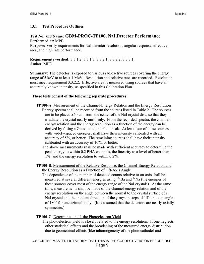
13.1 Test Procedure Outlines
Test No. and Name: GBM-PROC-TP100, NaI Detector PerformancePerformed at: MPEPurpose: Verify requirements for NaI detector resolution, angular response, effectivearea, and high rate performance.
Requirements verified: 3.3.1.2, 3.3.1.3, 3.3.2.1, 3.3.2.2, 3.3.3.1.Author: MPE
Summary: The detector is exposed to various radioactive sources covering the energyrange of 5 keV to at least 1 MeV. Resolution and relative rates are recorded. Resolutionmust meet requirement 3.3.2.2. Effective area is measured using sources that have anaccurately known intensity, as specified in this Calibration Plan.
These tests consist of the following separate procedures:
TP100-A. Measurement of the Channel-Energy Relation and the Energy ResolutionEnergy spectra shall be recorded from the sources listed in Table 2. The sources
are to be placed ≥50 cm from the center of the NaI crystal disc, so that theyirradiate the crystal nearly uniformly. From the recorded spectra, the channel-energy relation and the energy resolution as a function of the energy can bederived by fitting a Gaussian to the photopeak. At least four of these sources,with widely-spaced energies, shall have their intensity calibrated with anaccuracy of 5%, or better. The remaining sources shall have their intensitycalibrated with an accuracy of 10%, or better.
The above measurements shall be made with sufficient accuracy to determine thepeak energy to within 0.2 PHA channels, the linearity to a level of better than1%, and the energy resolution to within 0.2%.
TP100-B. Measurement of the Relative Response, the Channel-Energy Relation andthe Energy Resolution as a Function of Off-Axis AngleThe dependence of the number of detected counts relative to on-axis shall be
measured at several different energies using 133Ba and 22Na (the energies ofthese sources cover most of the energy range of the NaI crystals). At the sametime, measurements shall be made of the channel-energy relation and of theenergy resolution on the angle between the normal to the crystal surface of aNaI crystal and the incident direction of the γ-rays in steps of 15° up to an angleof 180° for one azimuth only. (It is assumed that the detectors are nearly axiallysymmetric.)
TP100-C. Determination of the Photoelectron YieldThe photoelectron yield is closely related to the energy resolution. If one neglects
other statistical effects and the broadening of the measured energy distributiondue to geometrical effects (like inhomogeneity of the photocathode) and
GBM-Plan-1014 Baseline
CHECK THE MASTER LIST VERIFY THAT THIS IS THE CORRECT VERSION BEFORE USEPage 10
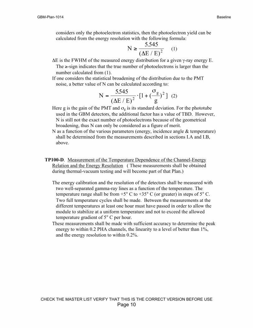
considers only the photoelectron statistics, then the photoelectron yield can becalculated from the energy resolution with the following formula:
NE E
≥5 545
2
.
( / )Δ(1)
ΔE is the FWHM of the measured energy distribution for a given γ-ray energy E.The ≥-sign indicates that the true number of photoelectrons is larger than thenumber calculated from (1).
If one considers the statistical broadening of the distribution due to the PMTnoise, a better value of N can be calculated according to:
NE E g
g= ⋅ +5545
12
2.
( / )[ ( ) ]
Δ
σ(2)
Here g is the gain of the PMT and σg is its standard deviation. For the phototubeused in the GBM detectors, the additional factor has a value of TBD. However,N is still not the exact number of photoelectrons because of the geometricalbroadening, thus N can only be considered as a figure of merit.
N as a function of the various parameters (energy, incidence angle & temperature)shall be determined from the measurements described in sections I.A and I.B,above.
TP100-D. Measurement of the Temperature Dependence of the Channel-EnergyRelation and the Energy Resolution ( These measurements shall be obtainedduring thermal-vacuum testing and will become part of that Plan.)
The energy calibration and the resolution of the detectors shall be measured withtwo well-separated gamma-ray lines as a function of the temperature. Thetemperature range shall be from +5° C to +35° C (or greater) in steps of 5° C.Two full temperature cycles shall be made. Between the measurements at thedifferent temperatures at least one hour must have passed in order to allow themodule to stabilize at a uniform temperature and not to exceed the allowedtemperature gradient of 5° C per hour.
These measurements shall be made with sufficient accuracy to determine the peakenergy to within 0.2 PHA channels, the linearity to a level of better than 1%,and the energy resolution to within 0.2%.
GBM-Plan-1014 Baseline
CHECK THE MASTER LIST VERIFY THAT THIS IS THE CORRECT VERSION BEFORE USEPage 11
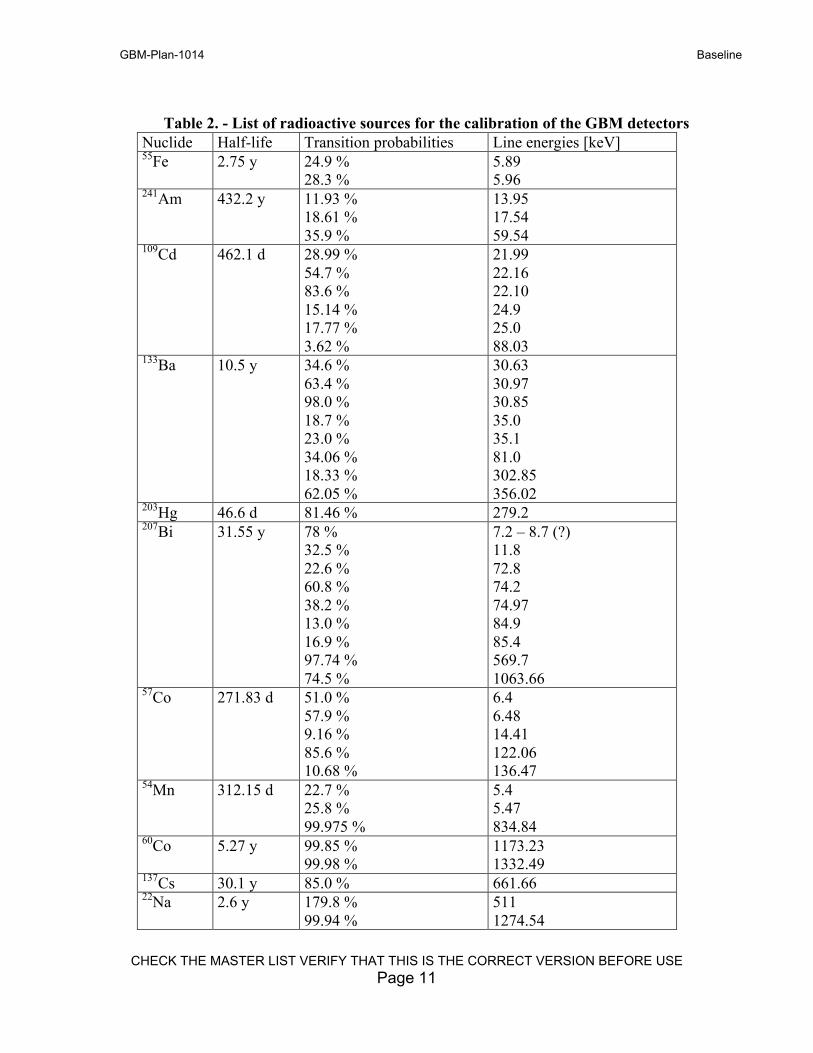
Table 2. - List of radioactive sources for the calibration of the GBM detectorsNuclide Half-life Transition probabilities Line energies [keV]55Fe 2.75 y 24.9 %
28.3 %5.895.96
241Am 432.2 y 11.93 %18.61 %35.9 %
13.9517.5459.54
109Cd 462.1 d 28.99 %54.7 %83.6 %15.14 %17.77 %3.62 %
21.9922.1622.1024.925.088.03
133Ba 10.5 y 34.6 %63.4 %98.0 %18.7 %23.0 %34.06 %18.33 %62.05 %
30.6330.9730.8535.035.181.0302.85356.02
203Hg 46.6 d 81.46 % 279.2207Bi 31.55 y 78 %
32.5 %22.6 %60.8 %38.2 %13.0 %16.9 %97.74 %74.5 %
7.2 – 8.7 (?)11.872.874.274.9784.985.4569.71063.66
57Co 271.83 d 51.0 %57.9 %9.16 %85.6 %10.68 %
6.46.4814.41122.06136.47
54Mn 312.15 d 22.7 %25.8 %99.975 %
5.45.47834.84
60Co 5.27 y 99.85 %99.98 %
1173.231332.49
137Cs 30.1 y 85.0 % 661.6622Na 2.6 y 179.8 %
99.94 %5111274.54
GBM-Plan-1014 Baseline
CHECK THE MASTER LIST VERIFY THAT THIS IS THE CORRECT VERSION BEFORE USEPage 12
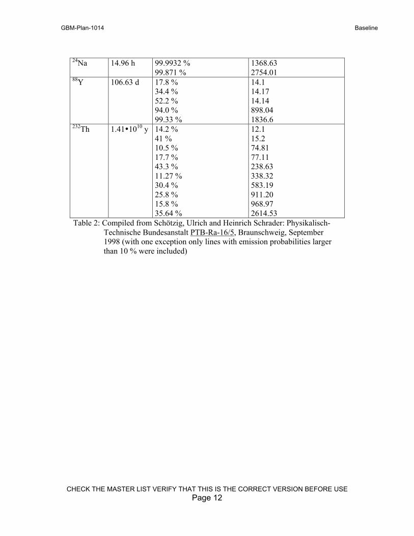
24Na 14.96 h 99.9932 %99.871 %
1368.632754.01
88Y 106.63 d 17.8 %34.4 %52.2 %94.0 %99.33 %
14.114.1714.14898.041836.6
232Th 1.41•1010 y 14.2 %41 %10.5 %17.7 %43.3 %11.27 %30.4 %25.8 %15.8 %35.64 %
12.115.274.8177.11238.63338.32583.19911.20968.972614.53
Table 2: Compiled from Schötzig, Ulrich and Heinrich Schrader: Physikalisch-Technische Bundesanstalt PTB-Ra-16/5, Braunschweig, September1998 (with one exception only lines with emission probabilities largerthan 10 % were included)
GBM-Plan-1014 Baseline
CHECK THE MASTER LIST VERIFY THAT THIS IS THE CORRECT VERSION BEFORE USEPage 13
Test No. and Name: GBM-PROC-TP101, NaI Low Energy CalibrationPerformed at: X Ray Test Facility (PUMA Facility at MPE)Purpose: Calibration of the NaI detectors at low energiesSummary: Calibrate from 3 keV to 40 keV. Trace out the k-edge of iodine in thedetector response. Measure effective area as a function of energy and angle.Requirements verified: none, but required to meet 3.3.5.Author: MPE
The purpose of the GBM Low Energy X-ray Calibrations, TP101, is to perform adetailed determination of the performance of the NaI detectors at low energies, thatcannot be performed with radioactive sources alone, due to the unavailability of lowenergy, mono-energetic photon sources, closely spaced in energy. The determination oflow-energy spectral measurements from GRBs is an important scientific objective of theGBM. Furthermore, absorbing materials in front of the detectors must be accuratelymeasures since they cannot be modeled with certainty.
The absolute efficiency of all NaI flight detectors and flight spares shall be determined atvarious closely-spaced, low-energy x-ray energies and incidence angles. The lowestenergy shall be ~3 keV, well below the expected low energy response of the GBM NaIdetectors. The highest energy measurements of these measurements shall be well abovethe iodine k-edge (32 keV), where the response is non-linear and even discontinuous. Itis recommended that these measurements extend to ~40 keV, if possible.
The x-ray beam characteristics such as the energy spread, beam background, absolutebeam flux monitoring, etc., will be factors in completing this section of the GBM-PROC-TP101. These parameters will be developed by MPE, in consultation with personnel ofthe PUMA X-ray Facility at MPE, when details of that facility are better known in thetimeframe of the GBM required calibrations.
The x-ray photon source of PUMA is expected to use a combination of x-ray tubes, andtube target materials, filters of different materials and thicknesses, and possibly a crystalmonochrometer.
A flight-like thermal cover is to be installed over the front face of the NaI detector, sincethis might have a significant effect on the low-energy performance. The number ofangular calibrations will be a sub-set of those in the comprehensive, medium energycalibrations of the NaI detectors.
[The low energy response of the detectors will be determined primarily by materials infront of the NaI crystal. While it is a design goal of GBM to have identical materials ineach detector, it cannot be well-modeled or easily verified, without these actualmeasurements.]
GBM-Plan-1014 Baseline
CHECK THE MASTER LIST VERIFY THAT THIS IS THE CORRECT VERSION BEFORE USEPage 14
Test No. and Name: GBM-PROC-TP105, NaI Detector FunctionalPerformed at: MPE, MSFC, S/C pre-integrationPurpose: Verify operation of PMT, preamps, and detector electronics.Summary: The detector is powered up and receipt of background counts is verified.Preamp power is cycled by command. These tests will be made using backgroundradiation or with radioactive sources (optional).Requirements verified: NoneAuthor: MPEUse: This procedure will be used at various times during the integration and test flow atMPE, MSFC, and Spectrum Astro, as determined by the test flow and at other times, asspecified by the P.I. or the GBM Systems Engineer.
GBM-Plan-1014 Baseline
CHECK THE MASTER LIST VERIFY THAT THIS IS THE CORRECT VERSION BEFORE USEPage 15
Test No. and Name: GBM-PROC-TP110, BGO Detector PerformancePerformed at: MPEPurpose: Verify requirements for BGO detector resolution, angular response, andeffective area.
Summary: The detector is exposed to radioactive sources covering the energy range of100 keV to at least 2.6 MeV and a range of angles. Resolution and relative rates arerecorded. Resolution must meet requirement 3.3.2.2. Effective area is measured usingsources that have accurately known intensity, as specified in the Calibration Plan.
Requirements verified: 3.3.2.1, 3.3.2.2, 3.3.3.1.Author: MPE
TP110-A. Measurement of the Channel-Energy Relation and the Energy ResolutionEnergy spectra shall be recorded from the sources listed in Table 2 (with principal
radiation >100 keV). The sources are to be placed ≥50 cm above thecylindrical surface of each BGO crystal lying in the middle plane perpendicularto the cylindrical axis located halfway between the two PMTs. From therecorded spectra, the channel-energy relation and the energy resolution as afunction of the energy can be derived by fitting a Gaussian to the photopeak. Atleast four of these sources, with widely-spaced energies, shall have theirintensity calibrated with an accuracy of 5%, or better. The remaining sourcesshall have their intensity calibrated with an accuracy of 10%, or better.
The above measurements shall be made with sufficient accuracy to determine thepeak energy to within 0.2 PHA channels, the linearity to a level of better than1%, and the energy resolution to within 0.2%.
TP110-B. Measurement of the Relative Response, the Channel-Energy Relation andthe Energy Resolution as a Function of Off-Axis AngleThe same measurements shall be performed with the BGO crystals as the NaI
detectors with the difference that the angle shall lie in one arbitrary planedefined by a radius and the cylindrical axis of the BGO detector. (On-axisrefers to a radius at the BGO detector centerline.) Again, 15° steps up to anangle of 90° shall be applied. Only two radioactive sources, 137Cs and 24Na,shall be used.
The above measurements shall be made with sufficient accuracy to determine theresponse of the detector to a level of better than 1%, relative to the on-axismeasurement. The energy-resolution measurement should be made with anaccuracy of better than 0.2%.
TP110-C. Determination of the Photoelectron YieldThe photoelectron yield is closely related to the energy resolution. If one neglects
other statistical effects and the broadening of the measured energy distributiondue to geometrical effects (like inhomogeneity of the photocathode) and
GBM-Plan-1014 Baseline
CHECK THE MASTER LIST VERIFY THAT THIS IS THE CORRECT VERSION BEFORE USEPage 16
considers only the photoelectron statistics, then the photoelectron yield can becalculated from the energy resolution with the following formula:
NE E
≥5 545
2
.
( / )Δ(1)
ΔE is the FWHM of the measured energy distribution for a given γ-ray energy E.The ≥-sign indicates that the true number of photoelectrons is larger than thenumber calculated from (1).
If one considers the statistical broadening of the distribution due to the PMTnoise, a better value of N can be calculated according to:
NE E g
g= ⋅ +5545
12
2.
( / )[ ( ) ]
Δ
σ(2)
Here g is the gain of the PMT and σg is its standard deviation. For the phototubeused in the GBM detectors, the additional factor has a value of TBD. However,N is still not the exact number of photoelectrons because of the geometricalbroadening, thus N can only be considered as a figure of merit.
N as a function of the various parameters (energy, incidence angle & temperature)shall be determined from the measurements described in sections I.A and I.B,above.
TP110-D. Measurement of the Temperature Dependence of the Channel-EnergyRelation and the Energy Resolution (These measurements shall be obtainedduring thermal-vacuum testing and will become part of that Plan.)
The energy calibration and the resolution of the detectors shall be measured withtwo well-separated gamma-ray lines as a function of the temperature. Thetemperature range shall be from +5° C to +35° C (or greater) in steps of 5° C.Two full temperature cycles shall be made. Between the measurements at thedifferent temperatures at least one hour must have passed in order to allow themodule to stabilize at a uniform temperature and not to exceed the allowedtemperature gradient of 5° C per hour.
These measurements shall be made with sufficient accuracy to determine the peakenergy to within 0.2 PHA channels, the linearity to a level of better than 1%,and the energy resolution to within 0.2%.
GBM-Plan-1014 Baseline
CHECK THE MASTER LIST VERIFY THAT THIS IS THE CORRECT VERSION BEFORE USEPage 17
Test No. and Name: GBM-PROC-TP111, BGO High Energy CalibrationPerformed at: Duke University Free-Electron Laser facilityPurpose:Summary: Determine the BGO detector linearity from 2 MeV to 35 MeV.
Author: Fishman/Lichti
Purpose: To test for non-linearity and saturation effects in a science model BGO crystaland PMT at high energy deposits and to determine the performance of the BGO detectorsat energies higher than that achievable with radioactive sources. (These tests will not beused to verify the detector off-diagonal elements, since the calibration set-up will be verydifferent from the flight configuration on the spacecraft.) In particular, non-linearities inBGO crystal light output and PMT response at high energies (but not high rates) shall beperformed. These effects cannot be performed with radioactive sources alone, due to theunavailability of energies higher than ~2.6 MeV.
The determination of high-energy spectral measurements from GRBs is a scientificobjective of the GBM, however, it is noted that spectral measurements above ~2MeV from GRBs will be limited by counting statistics, rather than by energycalibration accuracy. Furthermore, the GBM detector response matrices (DRMs)will be developed the required accuracy at these high energies to the requiredresolution. These calibrations will be performed at least six months prior tolaunch on the flight spare BGO detector, so that test results may be included in theDRMs.
The Duke University Free-Electron Laser Facility (DFELF) will be used for the GBMHigh Energy Gamma-Ray Calibrations. That facility is being utilized for tests ofthe MPE Mega Project, over roughly the same energy range, ~2 to 35 MeV, asrequired for the GBM BGO detectors. To avoid GBM hardware and schedulerisk, it is planned to use the GBM BGO Flight Spare Unit for the high energygamma-ray calibrations. The tests shall be performed at the following energies: 2,4, 8, 10, 12.5, 15, 17.5, 20, 25, 30, 35 MeV. At each energy, the peak channel,energy resolution shall be determined so that an overall linearity (or non-linearity)curve may be derived with an accuracy of 2%, or better.
GBM-Plan-1014 Baseline
CHECK THE MASTER LIST VERIFY THAT THIS IS THE CORRECT VERSION BEFORE USEPage 18
Test No. and Name: GBM-PROC-TP115, BGO Detector FunctionalPerformed at: MPE, MSFC, S/C pre-integrationPurpose: Verify operation of PMT, preamps, and detector electronics.Summary: The detector is powered up and receipt of background counts is verified.Preamp power is cycled by command. These tests will be made using backgroundradiation or with radioactive sources (optional). (This procedure will be almost identicalto PROC-TP-105, NaI Detector Functional.)
Requirements verified: NoneAuthor: MPEUse: This procedure will be used at various times during the integration and test flow atMPE, MSFC, and Spectrum Astro, as determined by the test flow and at other times, asspecified by the P.I. or the GBM Systems Engineer.
Test No. and Name: GBM-PROC-TP120, Detector Magnetic SusceptibilityPerformed at: MPEPurpose: Measure change in gain due to magnetic field variations.Summary: Detector is placed in a Helmholtz coil. Gain is measured at a range ofapplied magnetic field intensity, up to 1.5 gauss, and for various directions of themagnetic field with respect to the PMT axis.Required for 3.3.3 analysisAuthor: MPE
Procedure: Magnetic-Field SusceptibilityThe effects of magnetic fields on three NaI and one BGO detectors shall be
investigated at the detector level in three orthogonal directions and for fieldstrengths from –2 G to + 2G in steps of no less than 0.5 G. The magnetic fieldsare to be generated with three Helmholtz coils perpendicular to each other. Forthis investigation a 22Na source shall be used which shall be placed in the samegeometrical arrangement as described in section 4.1. For each of these 25measurements a pulse-height spectrum with sufficient counts so that the peakchannel can be determined to within 0.2%.. The magnetic shielding shall shieldthe magnetic fields up to |2| G so effectively that the impact on the peak positionis <1% and on the resolution <0.2%. The measurements shall be capable ofmeasuring these changes.
GBM-Plan-1014 Baseline
CHECK THE MASTER LIST VERIFY THAT THIS IS THE CORRECT VERSION BEFORE USEPage 19
Test No. and Name: GBM-PROC-TP121, Detector Gain vs. HVPerformed at: MPE, may be duplicated at NSSTC & Spectrum AstroRequired for Orbital Operations and Lifetime Assessment
The gain vs. PMT HV shall be measured for each PMT of each detector in order toprovide a rough estimate of the total lifetime of the PMTs, as determined by the aging(reduced gain) expected with time, as observed from similar type PMTs in orbit. Usingthe peaks at 32 keV and 662 keV from 137Cs, the peak position shall be determined as thehigh voltage is varied in increments of 50v over a range +/- 200 v. from the nominalsetting. These measurements shall be made with sufficient accuracy to determine thepeak energy to within 0.2 PHA channels.
Test No. and Name: GBM-PROC-TP605, System LinearityPerformed at: MSFCPurpose: Verify that the detector electronics and DPU meet the requirement for linearity.Summary: This test will use a combination of radioactive sources and a sliding pulser onthe test input for the EQMs, and will use only radioactive sources for the flight detectors.The output channel linearity is recorded.Requirements verified: 3.3.4.Author: Wilson
GBM-Plan-1014 Baseline
CHECK THE MASTER LIST VERIFY THAT THIS IS THE CORRECT VERSION BEFORE USEPage 20
Test No. and Name: GBM-PROC-TP610,Performed at: MSFCPurpose: Verify that GBM system meets the requirement for deadtime and gain stability at high rates.Summary: Radioactive sources are used to subject the detectors to high individual rates and subject theDPU to high combined rates. The deadtimes and gain changes are measured as a function of rate.Requirements verified: 3.4.2.2.2.Author: Fishman
High Rate Tests - Summary:1. Linearity Calibrations at High Count Rates Using a Pulse Generator
The preamplifier (FEE) of each detector shall be calibrated via its test input forsystem linearity over the full operational amplitude range at different countingrates up to a count rate of 300,000 cts/s. At least 5 different amplitudes spreadequally over the amplitude range shall be applied. The input pulses shall begenerated randomly with a pulse generator. The effects of overload pulses on arecorded pulse-height spectrum up to an equivalent energy of 2 GeV shall alsobe tested via this test input.
2. Linearity Calibrations at High Count Rates Using Radioactive SourcesThe influence of the counting rate on the stability and linearity has to be tested for
each detector by measuring the pulse-height spectrum of a line of a weak γ-raysource while a set of strong sources is moved on axis towards and away fromthe detector crystal (with this set of sources the shape of an average GRB shallbe simulated). From the measured pulse-height spectrum of the weak source thepeak position and the width of the distribution shall be determined as a functionof the overall count rate up to a count rate of 100,000 counts/s starting at acounting rate of 10,000 cts/s with increments space approximately a factor of1.5 apart. For the measurements with the NaI crystals an 55Fe source and a 22Nasource and for the measurements with the BGO crystals an 88Y source shall beused as the weak γ-ray source.
GBM-Plan-1014 Baseline
CHECK THE MASTER LIST VERIFY THAT THIS IS THE CORRECT VERSION BEFORE USEPage 21
Detector Response Matrices (DRMs) – Generation Plan – In a Separate Document, Prepared by R.M. Kippen
Summary: Detector-Response Matrices (DRMs)The DRM Generation Plan shall outline the steps leading to the generation of
GBM DRMs in outline and block diagram form. Details of the generation areleft to the discrimination of the GBM investigators. Note: These DRMs, whilethey play a critical role in the scientific data analysis, are not required for GBMdetector performance verification.
A comprehensive set of detector-response matrices shall be developed for bothdetector types. These DRMs will be produced by Monte Carlo calculationsusing a high-fidelity radiation-transport code like GEANT 4 with a high-resolution mass model for the detectors and the entire spacecraft. The energyrange of these calculations shall be from 5 keV to 40 MeV. Details of thesecalculations will provided in a separate plan, to be developed under the directionof Dr. R.M. Kippen/LANL, GBM Co-I. Data from the calibrations describedherein will be used in the verification of these DRMs.
GBM-Plan-1014 Baseline
CHECK THE MASTER LIST VERIFY THAT THIS IS THE CORRECT VERSION BEFORE USEPage 22
Test No. and Name: GBM-PROC-TP630, Short Energy CalibrationPerformed at: MSFC, Performed at times indicated in the test flow and at other timesrequested by the P.I.; System-level test.Purpose: Measure gains and verify that detector performance has not changed at selectedtimes in the test flow.Summary: One or two low intensity sources are positioned approximately 20cm in frontof each detector. Resolution and gain are measured for the detectors. The sources andthe accumulation times are left to the discretion of the P.I., Co-P.I., or the test conductor.Requirements verified: none. Author: Fishman
Test No. and Name: GBM-PROC-TP635, Long Energy CalibrationPerformed at: MSFC, S/C pre and post integration; System-level test.Purpose: Measure peak position and resolution of each detector over a wide range ofenergies so that a calibration curve can be obtained. Determine PMT gain coefficients.Summary: About 6 to 10 low intensity radioactive sources are positioned 20cm in frontof each detector. At least three values of HV are used (nominal, above nominal, andbelow nominal). Peak positions and resolution are measured. Gain vs. HV isdetermined.Requirements verified: 3.1.1.3.Author: Fishman
GBM-Plan-1014 Baseline
CHECK THE MASTER LIST VERIFY THAT THIS IS THE CORRECT VERSION BEFORE USEPage 23
Test No. and Name: GBM-PROC-TP805, S/C Integration Source SurveyPerformed at: S/C I&T, Following GBM integration on the spacecraftPurpose: Purpose: To quantitatively determine the amount of scattered gamma radiationfrom spacecraft (and LAT) into the GBM detectors at various angles of incidence,including backside detector angles and at several discrete energies.
Summary: Several radioactive sources (2 to 10 mCi) will be positioned at variouspositions around the spacecraft over a period of about 4 days.Requirements verified: none, but required for 3.3.5.
Author: Fishman
- Test Procedures: This Element of the Cal. Plan is under development jointlyby NSSTC & Spectrum Astro.
Summary:
Two isotopes are to be used in this survey: 57Co and 22Na
Radioactive source strength: ~10 milliCuries, each
Source handing and placement: To be performed by SpectrumAstro (or their sub-contractor.
Special precautions: Area roped-off with warning signs. Radiation training and use offilm badges by test personnel handling the sources and near the spacecraft duringthe tests. (These sources are not harmful to humans or spacecraft components,but they should be handled only by trained personnel.)
Tests to be performed:
A. Measurement of the Channel-Energy Relation and of the Energy Resolution,for all detectors (As in Section I.A.)
B. Scattering tests: Spectra shall be accumulated for three sources at twelvepositions around the spacecraft. Sufficient counts shall be accumulated so thatthe statistical errors are less than 2% at the peak energy and in scatteredenergy bands of width 50 keV or less.
C. Source locations: Sources shall be placed and collimated so that at least fourdetectors are illuminated at a distance of no less than 1.5 meters. Twelvedifferent locations on one side of the spacecraft shall be used, spaced by atleast 30 degrees from each other. The strong source shall be shielded by athick Pb shield in a manner to minimize illumination of room materials otherthan the in the direction of the spacecraft.
GBM Verification and Test PlanGBM-PLAN-1014
CHECK THE MASTER LIST VERIFY THAT THIS IS THE CORRECT VERSION BEFORE USEPage 24
E
Pre-EnvironmentalReview
SystemAcceptanceTest TP600
Thermal-Vac TestTP615
SystemLinearityTP605
High RateTest TP610
ThermalBalanceTest TP617
EMI / EMCTP620
AGC TestTP710
FinalFunctionalTest TP655
ShortEnergyCalibrationTP630
Pre-ShipReview
Ship toSpacecraftVendor
FunctionalTests TP650& 640
FunctionalTests TP650&640
FunctionalTestsTP650
BenchFunctionalTest TP655
Mount onSpacecraft
S/CInterfaceTestTP801
Join MissionI & Tschedule
T/V setupThermal Balancesetup
Long EnergyCalibrationTP635