Embed Size (px)
Citation preview

Back to Parameter Overview Page 1 of 53
CALIBRATION
PARAMETERS
VSI-2.0 LPG UNIVERSAL KIT
WORLD LEADER IN ALTERNATIVE FUEL SYSTEMS
Version: V2.4 03-2018 Copyright © Prins Autogassystemen B.V. 2018

Back to Parameter Overview Page 2 of 53
Back to Parameter Overview Page 3 of 53
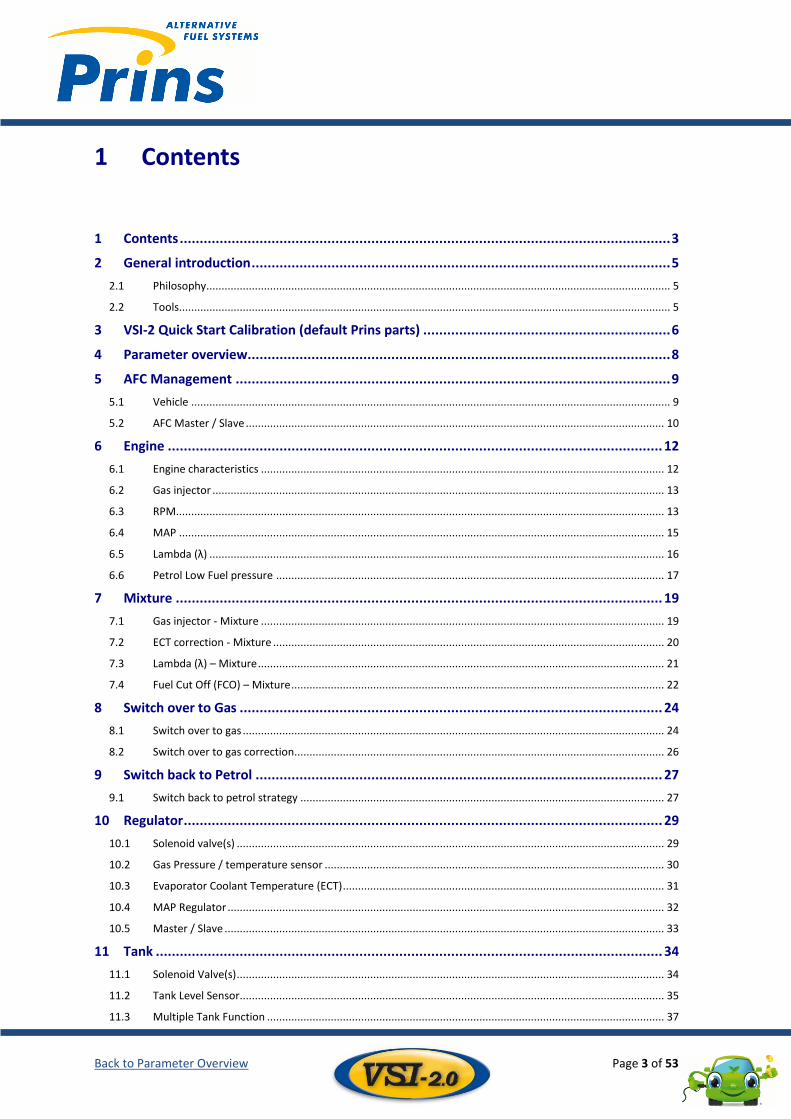
1 Contents
1 Contents ........................................................................................................................... 3
2 General introduction ......................................................................................................... 5
2.1 Philosophy......................................................................................................................................................... 5
2.2 Tools .................................................................................................................................................................. 5
3 VSI-2 Quick Start Calibration (default Prins parts) .............................................................. 6
4 Parameter overview.......................................................................................................... 8
5 AFC Management ............................................................................................................. 9
5.1 Vehicle .............................................................................................................................................................. 9
5.2 AFC Master / Slave .......................................................................................................................................... 10
6 Engine ............................................................................................................................ 12
6.1 Engine characteristics ..................................................................................................................................... 12
6.2 Gas injector ..................................................................................................................................................... 13
6.3 RPM................................................................................................................................................................. 13
6.4 MAP ................................................................................................................................................................ 15
6.5 Lambda (λ) ...................................................................................................................................................... 16
6.6 Petrol Low Fuel pressure ................................................................................................................................ 17
7 Mixture .......................................................................................................................... 19
7.1 Gas injector - Mixture ..................................................................................................................................... 19
7.2 ECT correction - Mixture ................................................................................................................................. 20
7.3 Lambda (λ) – Mixture ...................................................................................................................................... 21
7.4 Fuel Cut Off (FCO) – Mixture ........................................................................................................................... 22
8 Switch over to Gas .......................................................................................................... 24
8.1 Switch over to gas ........................................................................................................................................... 24
8.2 Switch over to gas correction.......................................................................................................................... 26
9 Switch back to Petrol ...................................................................................................... 27
9.1 Switch back to petrol strategy ........................................................................................................................ 27
10 Regulator ........................................................................................................................ 29
10.1 Solenoid valve(s) ............................................................................................................................................. 29
10.2 Gas Pressure / temperature sensor ................................................................................................................ 30
10.3 Evaporator Coolant Temperature (ECT) .......................................................................................................... 31
10.4 MAP Regulator ................................................................................................................................................ 32
10.5 Master / Slave ................................................................................................................................................. 33
11 Tank ............................................................................................................................... 34
11.1 Solenoid Valve(s) ............................................................................................................................................. 34
11.2 Tank Level Sensor............................................................................................................................................ 35
11.3 Multiple Tank Function ................................................................................................................................... 37
Back to Parameter Overview Page 4 of 53
11.4 Master / Slave ................................................................................................................................................. 40
12 Switch ............................................................................................................................ 41
12.1 Tank level indicator ......................................................................................................................................... 41
12.2 Fuel Status LED ................................................................................................................................................ 42
12.3 Switch Strategy ............................................................................................................................................... 42
12.4 Daylight Correction ......................................................................................................................................... 43
12.5 Beeper ............................................................................................................................................................. 43
13 Service / ValveCare ......................................................................................................... 44
13.1 Service ............................................................................................................................................................. 44
13.2 ValveCare ........................................................................................................................................................ 45
13.3 Critical Trouble codes...................................................................................................................................... 46
14 Supplement .................................................................................................................... 47
14.1 Supplement Master / Slave ............................................................................................................................. 47
This training manual was developed by Prins Autogassystemen B.V. © All rights reserved. No part of this publication may be reproduced or published without the permission of Prins Autogassystemen BV For more information: Prins Autogassystemen B.V. Jan Hilgersweg 22 5657 ES Eindhoven, the Netherlands Tel: (+31) 040-2547700 Fax: (+31) 040-2549749 www.prinsautogas.com [email protected]
Back to Parameter Overview Page 5 of 53
2 General introduction Philosophy......................................................................................................................................................... 5 2.1
Tools .................................................................................................................................................................. 5 2.2
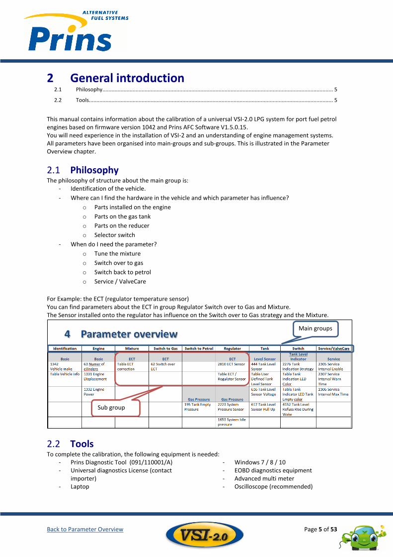
This manual contains information about the calibration of a universal VSI-2.0 LPG system for port fuel petrol engines based on firmware version 1042 and Prins AFC Software V1.5.0.15. You will need experience in the installation of VSI-2 and an understanding of engine management systems. All parameters have been organised into main-groups and sub-groups. This is illustrated in the Parameter Overview chapter.
Philosophy 2.1The philosophy of structure about the main group is:
- Identification of the vehicle.
- Where can I find the hardware in the vehicle and which parameter has influence?
o Parts installed on the engine
o Parts on the gas tank
o Parts on the reducer
o Selector switch
- When do I need the parameter?
o Tune the mixture
o Switch over to gas
o Switch back to petrol
o Service / ValveCare
For Example: the ECT (regulator temperature sensor) You can find parameters about the ECT in group Regulator Switch over to Gas and Mixture. The Sensor installed onto the regulator has influence on the Switch over to Gas strategy and the Mixture.
Tools 2.2To complete the calibration, the following equipment is needed:
- Prins Diagnostic Tool (091/110001/A) - Universal diagnostics License (contact
importer) - Laptop
- Windows 7 / 8 / 10 - EOBD diagnostics equipment - Advanced multi meter - Oscilloscope (recommended)
Main groups
Sub group
Back to Parameter Overview Page 6 of 53
3 VSI-2 Quick Start Calibration (default Prins parts) Minimum tank level of 20% 1)
Install the main fuse 2)
Install the latest firmware in the AFC (Switch stops blinking) 3)
Activate the AFC 4)
Start vehicle on petrol (system status “SS_Petrol_selected”) and check if all petrol related signals are being 5)
received
Turn off the air-conditioning, wipers, heaters, blowers lighting and other high powered accessories 6)
Set the parameters: 7)
Parameter Name
63 Number Of Cylinders
1335 Gas Injector Type
444 Tank Level Sensor
924 RPM Signal Source
619 RPM Trigger Level
297 RPM Factor
495 Regulator Map Reference (Only if Map sensor used)
533 AD 1 Sensor Selection (Only if Map sensor used)
2202 MAP Sensor (Only if Map sensor used)
1174 Lambda 1 Sensor (Only if Lambda sensor used)
1653 System Idle Pressure -1000 mbar if MAP sensor if used
195 Tank Empty Pressure -1000 mbar if MAP sensor if used
Check if the injectors have been installed correctly. Use the ‘Injector – Actuator test’ available in the 8)
diagnostic tool.
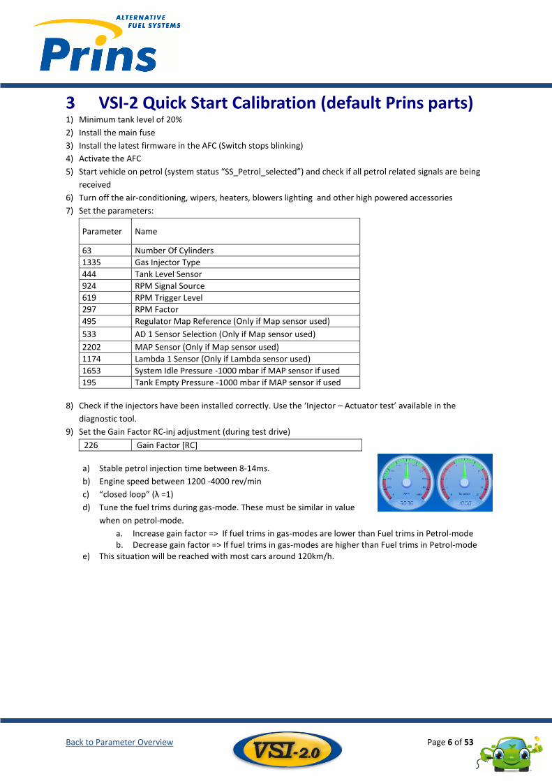
Set the Gain Factor RC-inj adjustment (during test drive) 9)
226 Gain Factor [RC]
a) Stable petrol injection time between 8-14ms.
b) Engine speed between 1200 -4000 rev/min
c) “closed loop” (λ =1)
d) Tune the fuel trims during gas-mode. These must be similar in value
when on petrol-mode.
a. Increase gain factor => If fuel trims in gas-modes are lower than Fuel trims in Petrol-mode b. Decrease gain factor => If fuel trims in gas-modes are higher than Fuel trims in Petrol-mode
e) This situation will be reached with most cars around 120km/h.
Back to Parameter Overview Page 7 of 53
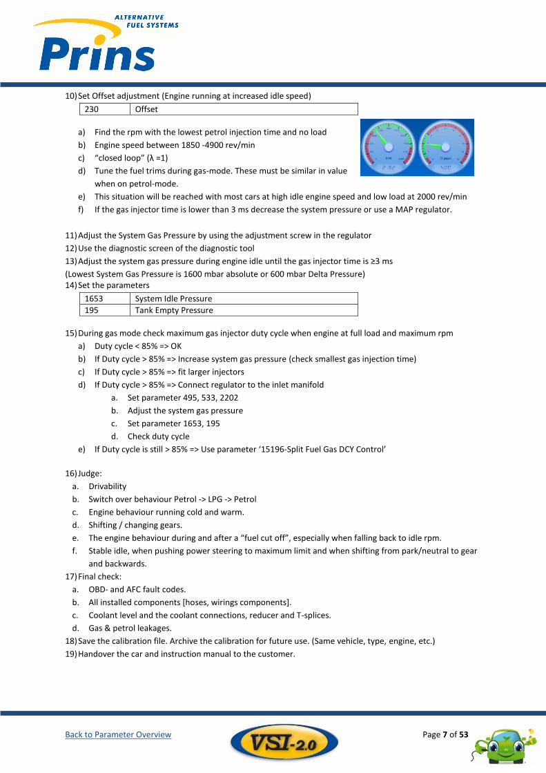
Set Offset adjustment (Engine running at increased idle speed) 10)
230 Offset
Find the rpm with the lowest petrol injection time and no load a)
Engine speed between 1850 -4900 rev/min b)
“closed loop” (λ =1) c)
Tune the fuel trims during gas-mode. These must be similar in value d)
when on petrol-mode.
This situation will be reached with most cars at high idle engine speed and low load at 2000 rev/min e)
If the gas injector time is lower than 3 ms decrease the system pressure or use a MAP regulator. f)
Adjust the System Gas Pressure by using the adjustment screw in the regulator 11)
Use the diagnostic screen of the diagnostic tool 12)
Adjust the system gas pressure during engine idle until the gas injector time is ≥3 ms 13)
(Lowest System Gas Pressure is 1600 mbar absolute or 600 mbar Delta Pressure) Set the parameters 14)
1653 System Idle Pressure
195 Tank Empty Pressure
During gas mode check maximum gas injector duty cycle when engine at full load and maximum rpm 15)
Duty cycle < 85% => OK a)
If Duty cycle > 85% => Increase system gas pressure (check smallest gas injection time) b)
If Duty cycle > 85% => fit larger injectors c)
If Duty cycle > 85% => Connect regulator to the inlet manifold d)
a. Set parameter 495, 533, 2202
b. Adjust the system gas pressure
c. Set parameter 1653, 195
d. Check duty cycle
If Duty cycle is still > 85% => Use parameter ‘15196-Split Fuel Gas DCY Control’ e)
Judge: 16)
a. Drivability
b. Switch over behaviour Petrol -> LPG -> Petrol
c. Engine behaviour running cold and warm.
d. Shifting / changing gears.
e. The engine behaviour during and after a “fuel cut off”, especially when falling back to idle rpm.
f. Stable idle, when pushing power steering to maximum limit and when shifting from park/neutral to gear
and backwards.
Final check: 17)
a. OBD- and AFC fault codes.
b. All installed components [hoses, wirings components].
c. Coolant level and the coolant connections, reducer and T-splices.
d. Gas & petrol leakages.
Save the calibration file. Archive the calibration for future use. (Same vehicle, type, engine, etc.) 18)
Handover the car and instruction manual to the customer. 19)
Back to Parameter Overview Page 8 of 53
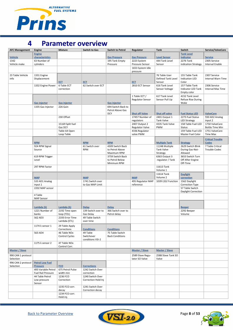
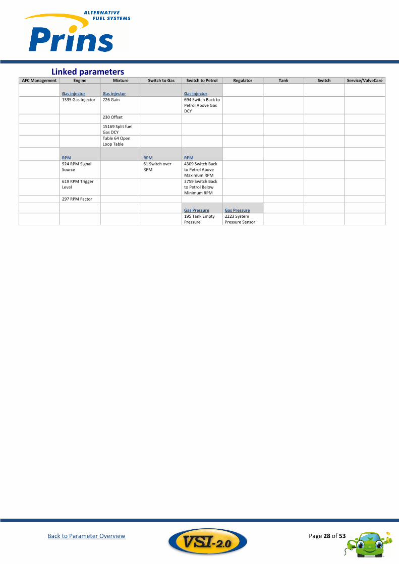
4 Parameter overview AFC Management Engine Mixture Switch to Gas Switch to Petrol Regulator Tank Switch Service/ValveCare
Vehicle
Engine characteristics Gas Pressure Gas Pressure Level Sensor
Tank Level Indicator Service
1342 Vehicle make
63 Number of cylinders
195 Tank Empty Pressure
2223 System Pressure Sensor
444 Tank Level Sensor
2276 Tank indication Strategy
2305 Service Interval Enable
1653 System Idle pressure
23 Table Vehicle info
1331 Engine Displacement
ECT ECT
ECT
76 Table User Defined Tank Level Sensor
155 Table Tank Indication LED Color
2307 Service Interval Warn Time
1332 Engine Power 6 Table ECT correction
62 Switch over ECT 2810 ECT Sensor 616 Tank Level Sensor Voltage
157 Table Tank Indicator LED Tank Empty color
2306 Service Interval Max Time
Gas injector Gas injector Gas injector
1 Table ECT / Regulator Sensor
617 Tank Level Sensor Pull Up
4152 Tank Level Refuse Rise During Wake
1335 Gas Injector 226 Gain 694 Switch Back to Petrol Above Gas DCY Shut off Valve Shut off valve Fuel Status LED ValveCare
230 Offset 17457 Number of regulators
2401 Output 1 Tank Valve
2273 Fuel Status LED Strategy
550 AD2 Analog input 2
15169 Split fuel Gas DCY
2407 Output 2 Regulator Valve
4335 Tank Valve PWM
158 Table Fuel LED Status
1750 ValveCare Bottle Time Min
Table 64 Open Loop Table
4336 Regulator valve PWM
159 Table Fuel LED Master Fuel Color
1751 ValveCare Time Max
RPM RPM RPM Multiple Tank Strategy Critical Trouble Codes
924 RPM Signal Source
61 Switch over RPM
4309 Switch Back to Petrol Above Maximum RPM
11248 Multiple Tank Valve Strategy
2629 Switch Blink During Gas-Not-Allowed
7 Table Critical Trouble Codes
619 RPM Trigger Level
3759 Switch Back to Petrol Below Minimum RPM
6363 Output 3 regulator / Tank
3653 Switch Turn Off After Engine Off-Time
297 RPM Factor
11613 Tank Volume 1
MAP MAP MAP
11614 Tank Volume 2
Daylight correction
533 AD1 Analog input 1
1741 Switch over to Gas MAP Limit
495 Regulator MAP reference
1039 LSS2 Function 1562 Daylight Correction Type
2202 MAP sensor 57 Table Switch Daylight Correction
4 Table MAP Sensor
Lambda (λ) Lambda (λ) Delay Delay
Beeper
1221 Number of banks
2192 Time open loop (TOL)
139 Switch over to Gas Delay
366 Switch over to Petrol delay
2292 Beeper Volume
562 AD3 2193 Error Time Lambda (ETL)
49 Table Switch over time
1174 λ sensor 1 29 Table Apply Corrections Conditions Conditions
563 AD4 46 Table NOx Control Cycles
49 Table Switchover conditions VSI-2
75 Table Switch Back Conditions
1175 λ sensor 2 47 Table NOx Control Corr.
Master / Slave
Master / Slave Master / Slave
990 CAN 1 protocol Selection
2589 Slave Regu-lator SO Valve
2588 Slave Tank SO Valve
996 CAN 2 protocol Selection
Petrol Low Fuel Pressure FCO Corrections
493 Variable Petrol Fuel Rail Pressure
675 Petrol Pulse width min
1242 Switch Over correction
44 Table Petrol Low pressure Sensor
1236 FCO Correction
1240 Switch Over Correction Hold Inj
1235 FCO corr. decay
1241 Switch Over Correction decay
1234 FCO corr. Hold inj.
Back to Parameter Overview Page 9 of 53
5 AFC Management Vehicle .............................................................................................................................................................. 9 5.1
AFC Master / Slave .......................................................................................................................................... 10 5.2
Vehicle 5.1
Description Enter the vehicle data in the AFC. This information is added into the log file and snapshot data. This makes it clear as to which vehicle the data and adjustments are from.
Conditions - This identification name will be used as file name, when saving the calibration.
Parameters
ID Name Value Unit Default (min/max)
Explanation
1342 Vehicle Make Value - N/A The vehicle name will also be stored in the log file.
23 Table
Vehicle identification
Table
VSI-2 Universal Default Calibration
This identification name will used as file name, when saving the calibration.
Linked parameters - None
Back to Parameter Overview Page 10 of 53
AFC Master / Slave 5.2
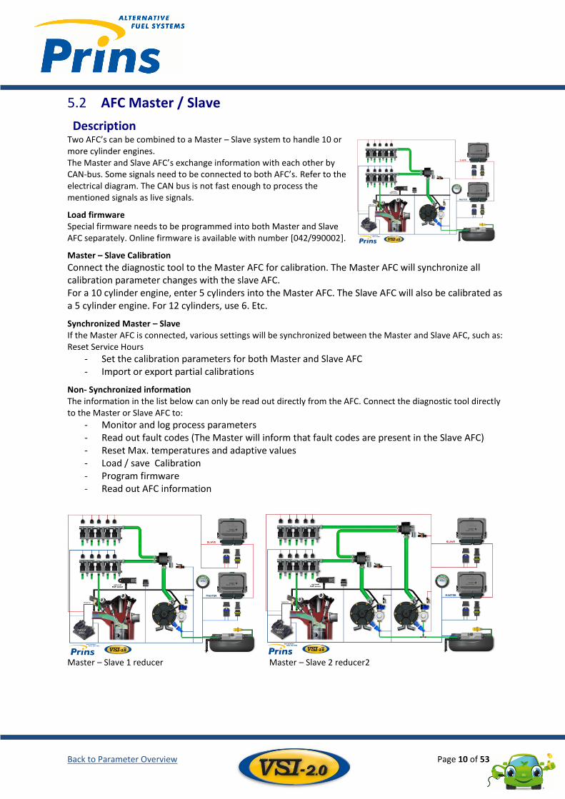
Description Two AFC’s can be combined to a Master – Slave system to handle 10 or more cylinder engines. The Master and Slave AFC’s exchange information with each other by CAN-bus. Some signals need to be connected to both AFC’s. Refer to the electrical diagram. The CAN bus is not fast enough to process the mentioned signals as live signals.
Load firmware Special firmware needs to be programmed into both Master and Slave AFC separately. Online firmware is available with number [042/990002].
Master – Slave Calibration
Connect the diagnostic tool to the Master AFC for calibration. The Master AFC will synchronize all calibration parameter changes with the slave AFC. For a 10 cylinder engine, enter 5 cylinders into the Master AFC. The Slave AFC will also be calibrated as a 5 cylinder engine. For 12 cylinders, use 6. Etc.
Synchronized Master – Slave If the Master AFC is connected, various settings will be synchronized between the Master and Slave AFC, such as: Reset Service Hours
- Set the calibration parameters for both Master and Slave AFC - Import or export partial calibrations
Non- Synchronized information The information in the list below can only be read out directly from the AFC. Connect the diagnostic tool directly to the Master or Slave AFC to:
- Monitor and log process parameters - Read out fault codes (The Master will inform that fault codes are present in the Slave AFC) - Reset Max. temperatures and adaptive values - Load / save Calibration - Program firmware - Read out AFC information
Master – Slave 1 reducer Master – Slave 2 reducer2
Back to Parameter Overview Page 11 of 53
Conditions - Master – Slave functionality is available in AFC V2.1 Full and all AFC versions that follow. - Connect signals to both AFC’s:
o Engine speed o CAN-bus to the same pins o + Petrol injector o MAP-sensor AD1 (if used) o AD2 (if used)
- Connect +12 battery to slave AFC to activate the slave-mode. (191/140018)
Calibration parameters – AFC management – Master / Slave
ID Name Value Unit Default (min/max)
Explanation
990 CAN 1 protocol Selection
Generic OBD Tester / Master-Slave / None
- Master-Slave Generic OBD Tester: OBD communication protocol Master Slave: Communication between master & slave None: No CAN communication active
996 CAN 2 protocol Selection
Generic OBD Tester / None
- None Generic OBD Tester: OBD communication protocol active None: No CAN communication active
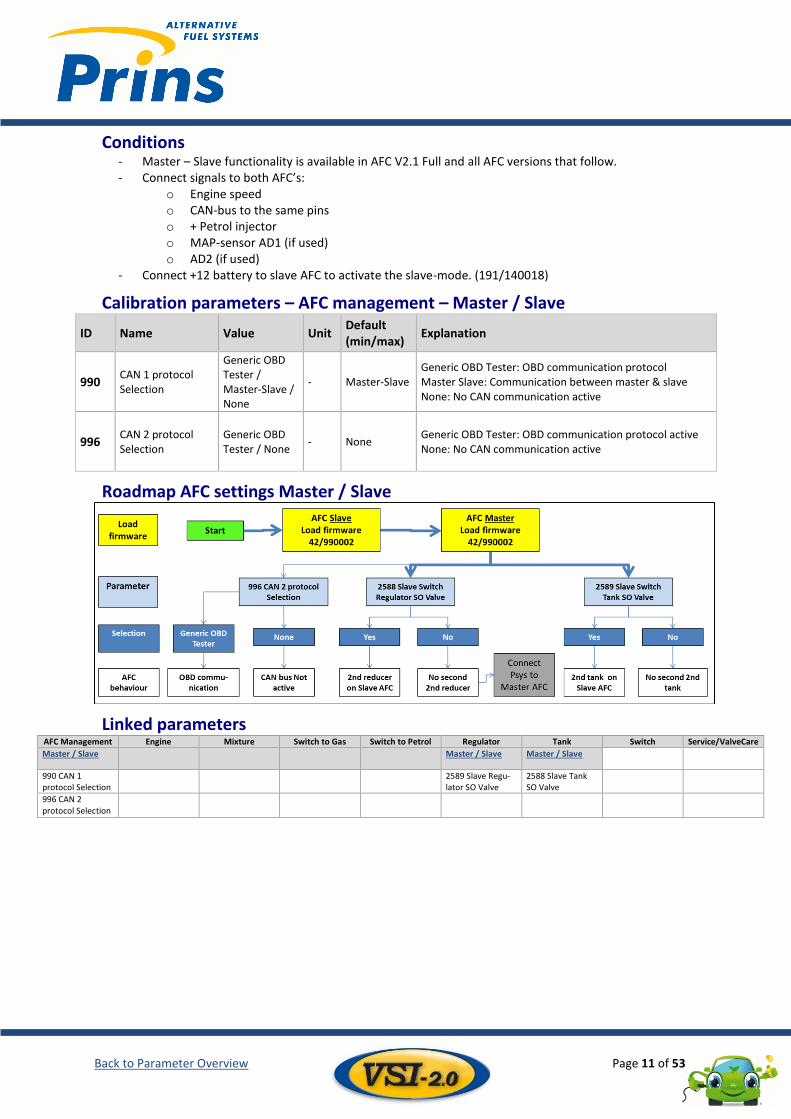
Roadmap AFC settings Master / Slave
Linked parameters AFC Management Engine Mixture Switch to Gas Switch to Petrol Regulator Tank Switch Service/ValveCare
Master / Slave
Master / Slave Master / Slave
990 CAN 1 protocol Selection
2589 Slave Regu-lator SO Valve
2588 Slave Tank SO Valve
996 CAN 2 protocol Selection
Back to Parameter Overview Page 12 of 53
6 Engine Engine characteristics ..................................................................................................................................... 12 6.1
Gas injector ..................................................................................................................................................... 13 6.2
RPM................................................................................................................................................................. 13 6.3
MAP ................................................................................................................................................................ 15 6.4
Lambda (λ) ...................................................................................................................................................... 16 6.5
Petrol Low Fuel pressure ................................................................................................................................ 17 6.6
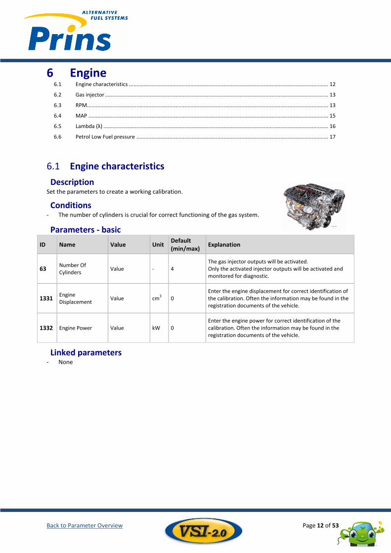
Engine characteristics 6.1
Description Set the parameters to create a working calibration.
Conditions - The number of cylinders is crucial for correct functioning of the gas system.
Parameters - basic
ID Name Value Unit Default (min/max)
Explanation
63 Number Of Cylinders
Value - 4 The gas injector outputs will be activated. Only the activated injector outputs will be activated and monitored for diagnostic.
1331 Engine Displacement
Value cm3 0
Enter the engine displacement for correct identification of the calibration. Often the information may be found in the registration documents of the vehicle.
1332 Engine Power Value kW 0 Enter the engine power for correct identification of the calibration. Often the information may be found in the registration documents of the vehicle.
Linked parameters - None
Back to Parameter Overview Page 13 of 53
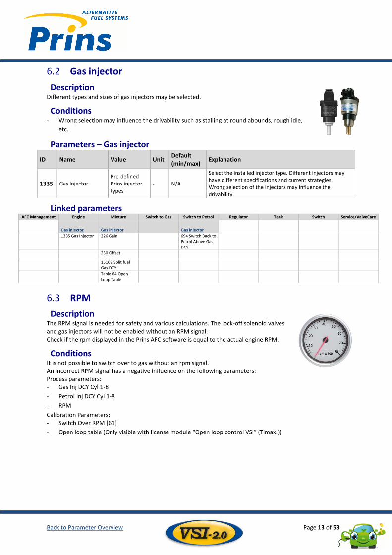
Gas injector 6.2
Description Different types and sizes of gas injectors may be selected.
Conditions - Wrong selection may influence the drivability such as stalling at round abounds, rough idle,
etc.
Parameters – Gas injector
ID Name Value Unit Default (min/max)
Explanation
1335 Gas Injector Pre-defined Prins injector types
- N/A
Select the installed injector type. Different injectors may have different specifications and current strategies. Wrong selection of the injectors may influence the drivability.
Linked parameters AFC Management Engine Mixture Switch to Gas Switch to Petrol Regulator Tank Switch Service/ValveCare
Gas injector Gas injector Gas injector
1335 Gas Injector 226 Gain 694 Switch Back to Petrol Above Gas DCY
230 Offset
15169 Split fuel Gas DCY
Table 64 Open Loop Table
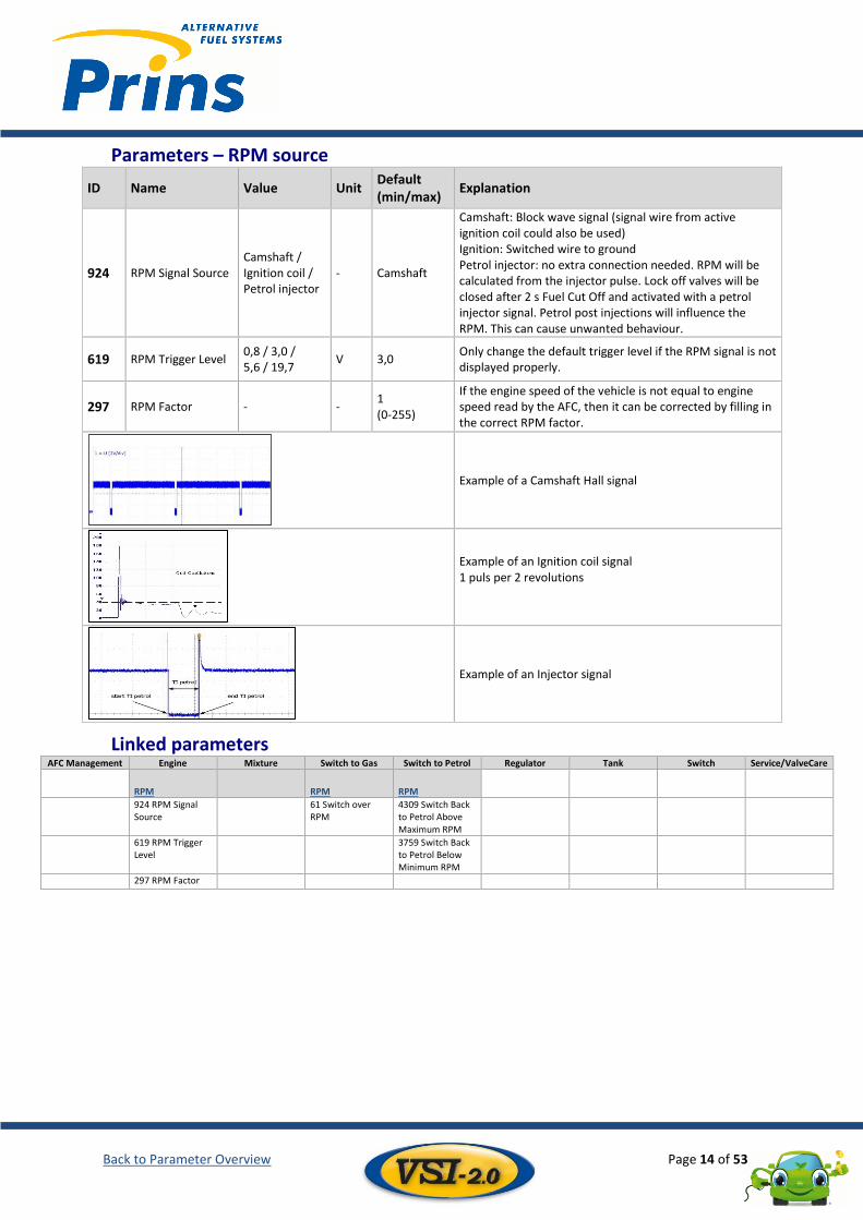
RPM 6.3
Description The RPM signal is needed for safety and various calculations. The lock-off solenoid valves and gas injectors will not be enabled without an RPM signal. Check if the rpm displayed in the Prins AFC software is equal to the actual engine RPM.
Conditions It is not possible to switch over to gas without an rpm signal. An incorrect RPM signal has a negative influence on the following parameters: Process parameters: - Gas Inj DCY Cyl 1-8
- Petrol Inj DCY Cyl 1-8
- RPM
Calibration Parameters: - Switch Over RPM [61]
- Open loop table (Only visible with license module “Open loop control VSI” (Timax.))
Back to Parameter Overview Page 14 of 53
Parameters – RPM source
ID Name Value Unit Default (min/max)
Explanation
924 RPM Signal Source Camshaft / Ignition coil / Petrol injector
- Camshaft
Camshaft: Block wave signal (signal wire from active ignition coil could also be used) Ignition: Switched wire to ground Petrol injector: no extra connection needed. RPM will be calculated from the injector pulse. Lock off valves will be closed after 2 s Fuel Cut Off and activated with a petrol injector signal. Petrol post injections will influence the RPM. This can cause unwanted behaviour.
619 RPM Trigger Level 0,8 / 3,0 / 5,6 / 19,7
V 3,0 Only change the default trigger level if the RPM signal is not displayed properly.
297 RPM Factor - - 1 (0-255)
If the engine speed of the vehicle is not equal to engine speed read by the AFC, then it can be corrected by filling in the correct RPM factor.
Example of a Camshaft Hall signal
Example of an Ignition coil signal 1 puls per 2 revolutions
Example of an Injector signal
Linked parameters AFC Management Engine Mixture Switch to Gas Switch to Petrol Regulator Tank Switch Service/ValveCare
RPM RPM RPM
924 RPM Signal Source
61 Switch over RPM
4309 Switch Back to Petrol Above Maximum RPM
619 RPM Trigger Level
3759 Switch Back to Petrol Below Minimum RPM
297 RPM Factor
Back to Parameter Overview Page 15 of 53
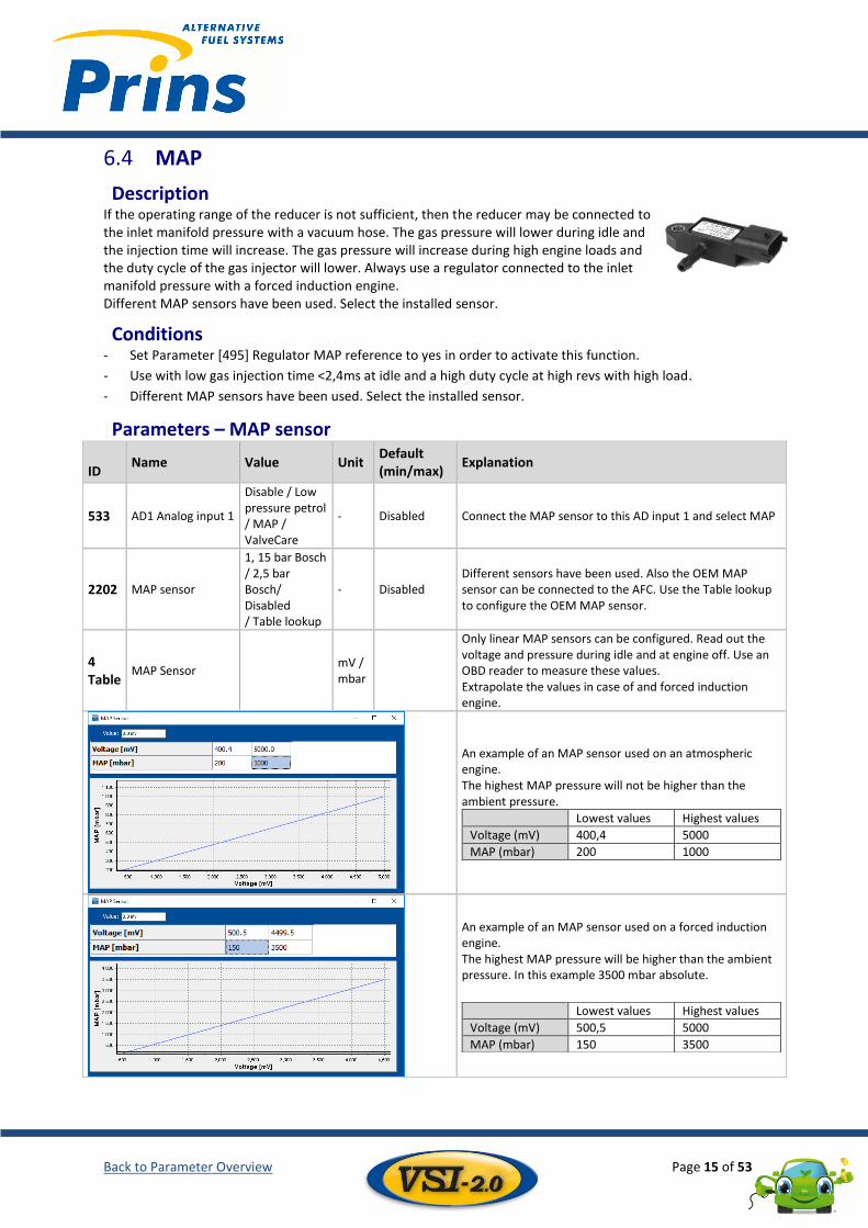
MAP 6.4
Description If the operating range of the reducer is not sufficient, then the reducer may be connected to the inlet manifold pressure with a vacuum hose. The gas pressure will lower during idle and the injection time will increase. The gas pressure will increase during high engine loads and the duty cycle of the gas injector will lower. Always use a regulator connected to the inlet manifold pressure with a forced induction engine. Different MAP sensors have been used. Select the installed sensor.
Conditions - Set Parameter [495] Regulator MAP reference to yes in order to activate this function.
- Use with low gas injection time <2,4ms at idle and a high duty cycle at high revs with high load.
- Different MAP sensors have been used. Select the installed sensor.
Parameters – MAP sensor ID
Name Value Unit Default (min/max)
Explanation
533 AD1 Analog input 1
Disable / Low pressure petrol / MAP / ValveCare
- Disabled Connect the MAP sensor to this AD input 1 and select MAP
2202 MAP sensor
1, 15 bar Bosch / 2,5 bar Bosch/ Disabled / Table lookup
- Disabled Different sensors have been used. Also the OEM MAP sensor can be connected to the AFC. Use the Table lookup to configure the OEM MAP sensor.
4 Table
MAP Sensor mV / mbar
Only linear MAP sensors can be configured. Read out the voltage and pressure during idle and at engine off. Use an OBD reader to measure these values. Extrapolate the values in case of and forced induction engine.
An example of an MAP sensor used on an atmospheric engine. The highest MAP pressure will not be higher than the ambient pressure.
Lowest values Highest values
Voltage (mV) 400,4 5000
MAP (mbar) 200 1000
An example of an MAP sensor used on a forced induction engine. The highest MAP pressure will be higher than the ambient pressure. In this example 3500 mbar absolute.
Lowest values Highest values
Voltage (mV) 500,5 5000
MAP (mbar) 150 3500
Back to Parameter Overview Page 16 of 53
Linked parameters AFC Management Engine Mixture Switch to Gas Switch to Petrol Regulator Tank Switch Service/ValveCare
MAP MAP MAP
533 AD1 Analog input 1
1741 Switch over to Gas MAP Limit
495 Regulator MAP reference
2202 MAP sensor
4 Table MAP Sensor
Lambda (λ) 6.5
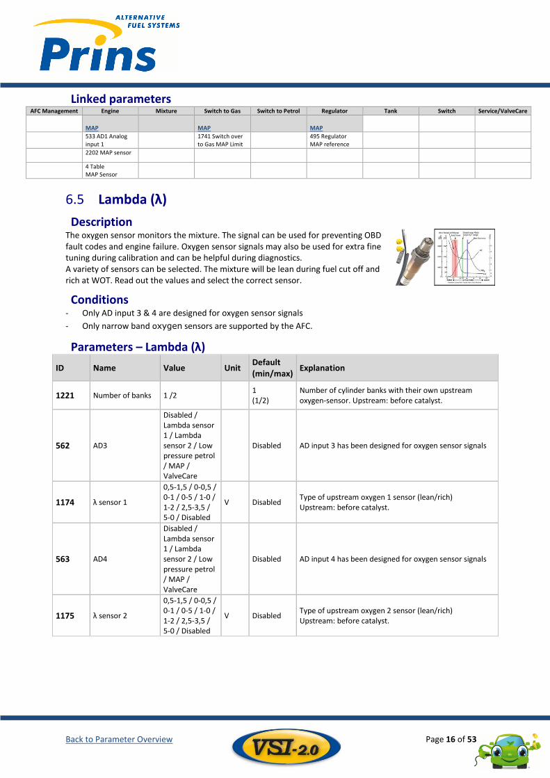
Description The oxygen sensor monitors the mixture. The signal can be used for preventing OBD fault codes and engine failure. Oxygen sensor signals may also be used for extra fine tuning during calibration and can be helpful during diagnostics. A variety of sensors can be selected. The mixture will be lean during fuel cut off and rich at WOT. Read out the values and select the correct sensor.
Conditions - Only AD input 3 & 4 are designed for oxygen sensor signals
- Only narrow band oxygen sensors are supported by the AFC.
Parameters – Lambda (λ)
ID Name Value Unit Default (min/max)
Explanation
1221 Number of banks 1 /2 1 (1/2)
Number of cylinder banks with their own upstream oxygen-sensor. Upstream: before catalyst.
562 AD3
Disabled / Lambda sensor 1 / Lambda sensor 2 / Low pressure petrol / MAP / ValveCare
Disabled AD input 3 has been designed for oxygen sensor signals
1174 λ sensor 1
0,5-1,5 / 0-0,5 / 0-1 / 0-5 / 1-0 / 1-2 / 2,5-3,5 / 5-0 / Disabled
V Disabled Type of upstream oxygen 1 sensor (lean/rich) Upstream: before catalyst.
563 AD4
Disabled / Lambda sensor 1 / Lambda sensor 2 / Low pressure petrol / MAP / ValveCare
Disabled AD input 4 has been designed for oxygen sensor signals
1175 λ sensor 2
0,5-1,5 / 0-0,5 / 0-1 / 0-5 / 1-0 / 1-2 / 2,5-3,5 / 5-0 / Disabled
V Disabled Type of upstream oxygen 2 sensor (lean/rich) Upstream: before catalyst.
Back to Parameter Overview Page 17 of 53
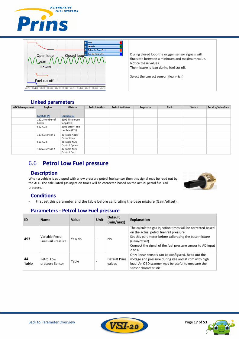
During closed loop the oxygen sensor signals will fluctuate between a minimum and maximum value. Notice these values. The mixture is lean during fuel cut off. Select the correct sensor. (lean-rich)
Linked parameters AFC Management Engine Mixture Switch to Gas Switch to Petrol Regulator Tank Switch Service/ValveCare
Lambda (λ) Lambda (λ)
1221 Number of banks
2192 Time open loop (TOL)
562 AD3 2193 Error Time Lambda (ETL)
1174 λ sensor 1 29 Table Apply Corrections
563 AD4 46 Table NOx Control Cycles
1175 λ sensor 2 47 Table NOx Control Corr.
Petrol Low Fuel pressure 6.6
Description When a vehicle is equipped with a low pressure petrol fuel sensor then this signal may be read out by the AFC. The calculated gas injection times will be corrected based on the actual petrol fuel rail pressure.
Conditions - First set this parameter and the table before calibrating the base mixture (Gain/offset).
Parameters - Petrol Low Fuel pressure
ID Name Value Unit Default (min/max)
Explanation
493 Variable Petrol Fuel Rail Pressure
Yes/No - No
The calculated gas injection times will be corrected based on the actual petrol fuel rail pressure. Set this parameter before calibrating the base mixture (Gain/offset). Connect the signal of the fuel pressure sensor to AD input 2 or 4.
44 Table
Petrol Low pressure Sensor
Table - Default Prins values
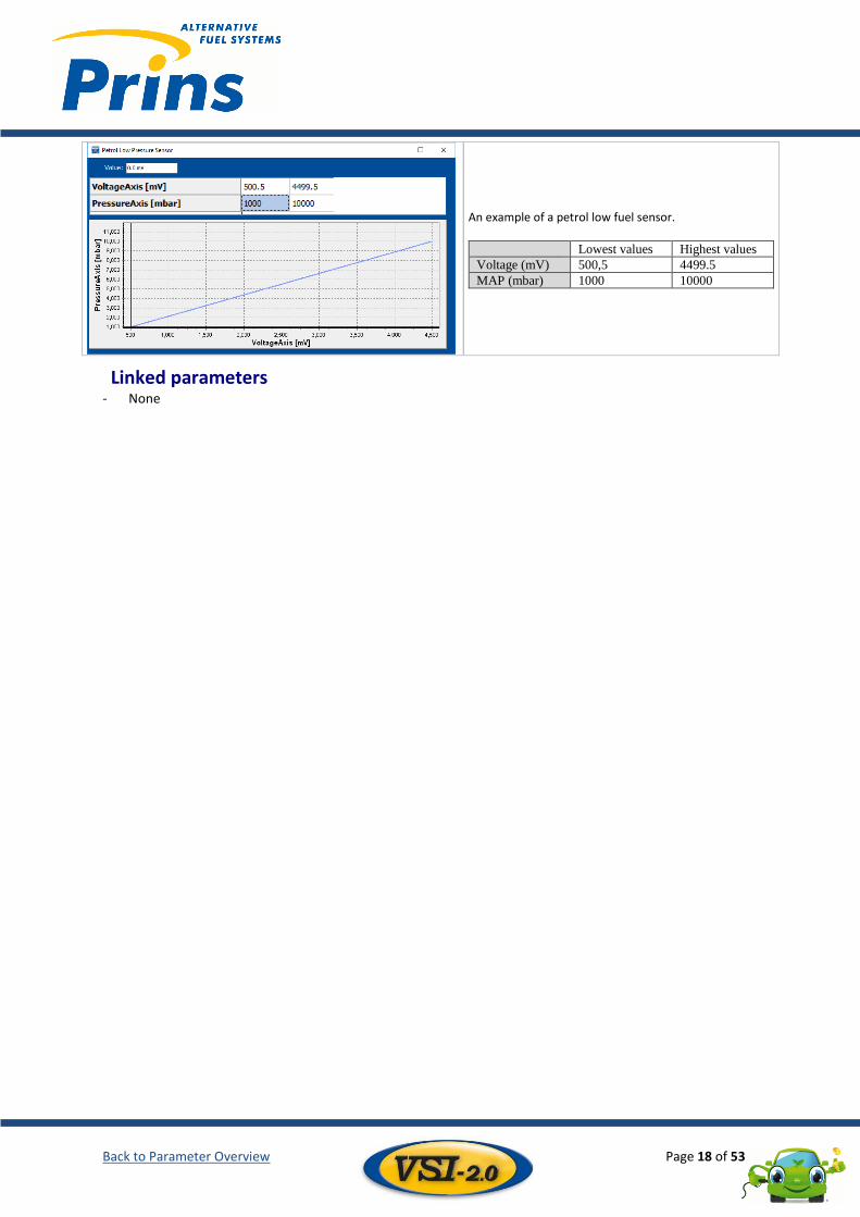
Only linear sensors can be configured. Read out the voltage and pressure during idle and at rpm with high load. An OBD scanner may be useful to measure the sensor characteristic!
Fuel cut off
Lean mixture
Open loop Closed loop
Back to Parameter Overview Page 18 of 53
An example of a petrol low fuel sensor.
Lowest values Highest values
Voltage (mV) 500,5 4499.5
MAP (mbar) 1000 10000
Linked parameters - None
Back to Parameter Overview Page 19 of 53
7 Mixture Gas injector - Mixture ..................................................................................................................................... 19 7.1
ECT correction - Mixture ................................................................................................................................. 20 7.2
Lambda (λ) – Mixture ...................................................................................................................................... 21 7.3
Fuel Cut Off (FCO) – Mixture ........................................................................................................................... 22 7.4
Gas injector - Mixture 7.1
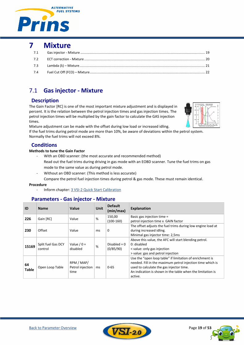
Description The Gain Factor [RC] is one of the most important mixture adjustment and is displayed in percent. It is the relation between the petrol injection times and gas injection times. The petrol injection times will be multiplied by the gain factor to calculate the GAS injection times. Mixture adjustment can be made with the offset during low load or increased idling. If the fuel trims during petrol mode are more than 10%, be aware of deviations within the petrol system. Normally the fuel trims will not exceed 8%.
Conditions Methods to tune the Gain Factor
- With an OBD scanner: (the most accurate and recommended method)
Read out the fuel trims during driving in gas mode with an EOBD scanner. Tune the fuel trims on gas
mode to the same value as during petrol mode.
- Without an OBD scanner: (This method is less accurate)
Compare the petrol fuel injection times during petrol & gas mode. These must remain identical.
Procedure - Inform chapter: 3 VSI-2 Quick Start Calibration
Parameters - Gas injector - Mixture
ID Name Value Unit Default (min/max)
Explanation
226 Gain [RC] Value % 150,00 (100-160)
Basic gas injection time = petrol injection time x GAIN factor
230 Offset Value ms 0 The offset adjusts the fuel trims during low engine load at during increased idling. Minimal gas injector time: 2,5ms
15169 Split fuel Gas DCY control
Value / 0 = disabled
% Disabled = 0 (0/85/90)
Above this value, the AFC will start blending petrol. 0: disabled < value: only gas injection > value: gas and petrol injection
64 Table
Open Loop Table RPM / MAP/ Petrol injection time
ms 0-65
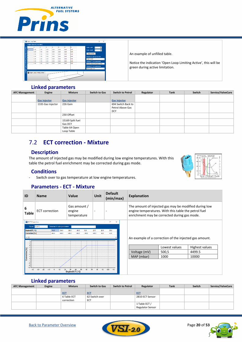
Use the “open loop table” if limitation of enrichment is needed. Fill in the maximum petrol injection time which is used to calculate the gas injector time. An indication is shown in the table when the limitation is active.
Back to Parameter Overview Page 20 of 53
An example of unfilled table. Notice the indication ‘Open Loop Limiting Active’, this will be green during active limitation.
Linked parameters AFC Management Engine Mixture Switch to Gas Switch to Petrol Regulator Tank Switch Service/ValveCare
Gas injector Gas injector Gas injector
1335 Gas Injector 226 Gain 694 Switch Back to Petrol Above Gas DCY
230 Offset
15169 Split fuel Gas DCY
Table 64 Open Loop Table
ECT correction - Mixture 7.2
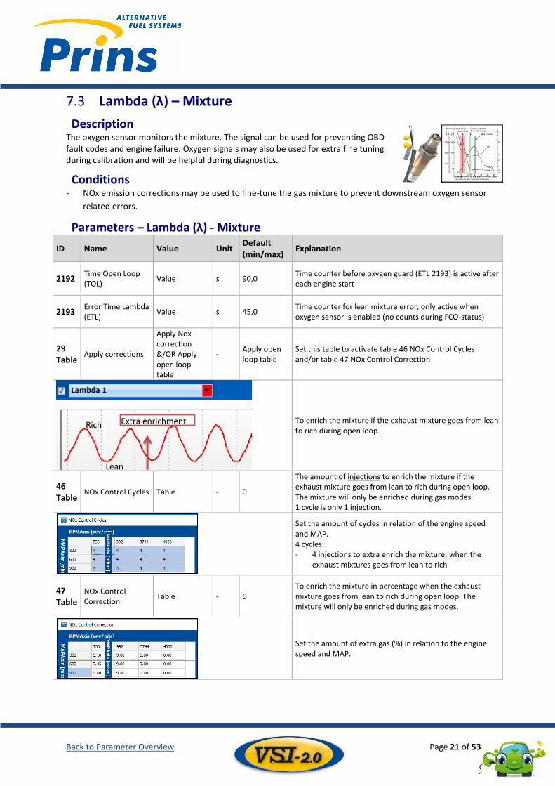
Description The amount of injected gas may be modified during low engine temperatures. With this table the petrol fuel enrichment may be corrected during gas mode.
Conditions - Switch over to gas temperature at low engine temperatures.
Parameters - ECT - Mixture
ID Name Value Unit Default (min/max)
Explanation
6 Table
ECT correction Gas amount / engine temperature
- - The amount of injected gas may be modified during low engine temperatures. With this table the petrol fuel enrichment may be corrected during gas mode.
An example of a correction of the injected gas amount.
Lowest values Highest values
Voltage (mV) 500,5 4499.5
MAP (mbar) 1000 10000
Linked parameters AFC Management Engine Mixture Switch to Gas Switch to Petrol Regulator Tank Switch Service/ValveCare
ECT ECT
ECT
6 Table ECT correction
62 Switch over ECT
2810 ECT Sensor
1 Table ECT / Regulator Sensor
Back to Parameter Overview Page 21 of 53
Lambda (λ) – Mixture 7.3
Description The oxygen sensor monitors the mixture. The signal can be used for preventing OBD fault codes and engine failure. Oxygen signals may also be used for extra fine tuning during calibration and will be helpful during diagnostics.
Conditions - NOx emission corrections may be used to fine-tune the gas mixture to prevent downstream oxygen sensor
related errors.
Parameters – Lambda (λ) - Mixture
ID Name Value Unit Default (min/max)
Explanation
2192 Time Open Loop (TOL)
Value s 90,0 Time counter before oxygen guard (ETL 2193) is active after each engine start
2193 Error Time Lambda (ETL)
Value s 45,0 Time counter for lean mixture error, only active when oxygen sensor is enabled (no counts during FCO-status)
29 Table
Apply corrections
Apply Nox correction &/OR Apply open loop table
- Apply open loop table
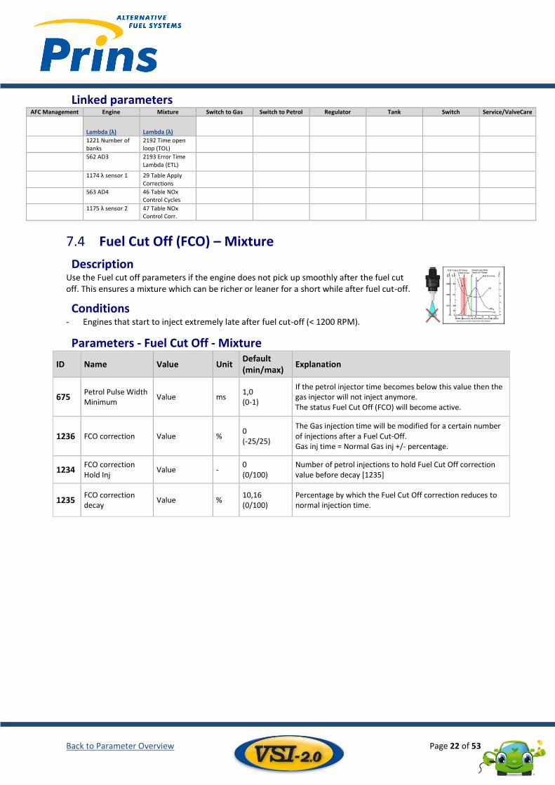
Set this table to activate table 46 NOx Control Cycles and/or table 47 NOx Control Correction
To enrich the mixture if the exhaust mixture goes from lean to rich during open loop.
46 Table
NOx Control Cycles Table - 0
The amount of injections to enrich the mixture if the exhaust mixture goes from lean to rich during open loop. The mixture will only be enriched during gas modes. 1 cycle is only 1 injection.
Set the amount of cycles in relation of the engine speed and MAP. 4 cycles: - 4 injections to extra enrich the mixture, when the
exhaust mixtures goes from lean to rich
47 Table
NOx Control Correction
Table - 0 To enrich the mixture in percentage when the exhaust mixture goes from lean to rich during open loop. The mixture will only be enriched during gas modes.
Set the amount of extra gas (%) in relation to the engine speed and MAP.
Extra enrichment
Lean
Rich
Back to Parameter Overview Page 22 of 53
Linked parameters AFC Management Engine Mixture Switch to Gas Switch to Petrol Regulator Tank Switch Service/ValveCare
Lambda (λ) Lambda (λ)
1221 Number of banks
2192 Time open loop (TOL)
562 AD3 2193 Error Time Lambda (ETL)
1174 λ sensor 1 29 Table Apply Corrections
563 AD4 46 Table NOx Control Cycles
1175 λ sensor 2 47 Table NOx Control Corr.
Fuel Cut Off (FCO) – Mixture 7.4
Description Use the Fuel cut off parameters if the engine does not pick up smoothly after the fuel cut off. This ensures a mixture which can be richer or leaner for a short while after fuel cut-off.
Conditions - Engines that start to inject extremely late after fuel cut-off (< 1200 RPM).
Parameters - Fuel Cut Off - Mixture
ID Name Value Unit Default (min/max)
Explanation
675 Petrol Pulse Width Minimum
Value ms 1,0 (0-1)
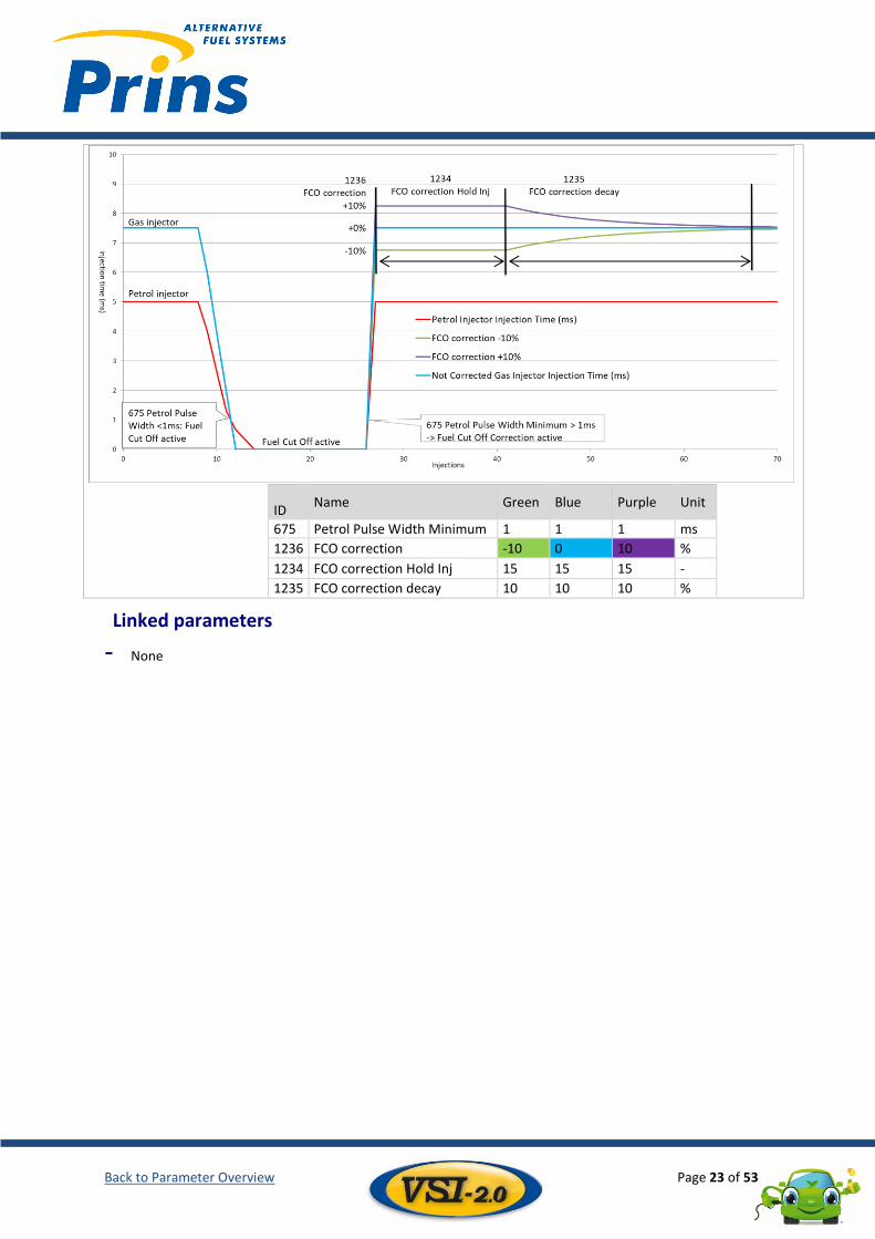
If the petrol injector time becomes below this value then the gas injector will not inject anymore. The status Fuel Cut Off (FCO) will become active.
1236 FCO correction Value % 0 (-25/25)
The Gas injection time will be modified for a certain number of injections after a Fuel Cut-Off. Gas inj time = Normal Gas inj +/- percentage.
1234 FCO correction Hold Inj
Value - 0 (0/100)
Number of petrol injections to hold Fuel Cut Off correction value before decay [1235]
1235 FCO correction decay
Value % 10,16 (0/100)
Percentage by which the Fuel Cut Off correction reduces to normal injection time.
Back to Parameter Overview Page 23 of 53
ID Name Green Blue Purple Unit
675 Petrol Pulse Width Minimum 1 1 1 ms
1236 FCO correction -10 0 10 %
1234 FCO correction Hold Inj 15 15 15 -
1235 FCO correction decay 10 10 10 %
Linked parameters
- None
Back to Parameter Overview Page 24 of 53
8 Switch over to Gas Switch over to gas ........................................................................................................................................... 24 8.1
Switch over to gas correction.......................................................................................................................... 26 8.2
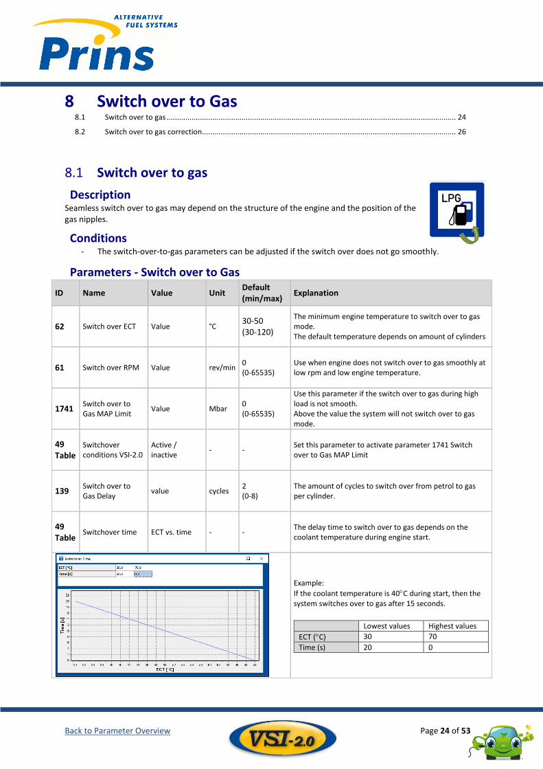
Switch over to gas 8.1
Description Seamless switch over to gas may depend on the structure of the engine and the position of the gas nipples.
Conditions - The switch-over-to-gas parameters can be adjusted if the switch over does not go smoothly.
Parameters - Switch over to Gas
ID Name Value Unit Default (min/max)
Explanation
62 Switch over ECT Value °C 30-50 (30-120)
The minimum engine temperature to switch over to gas mode. The default temperature depends on amount of cylinders
61 Switch over RPM Value rev/min 0 (0-65535)
Use when engine does not switch over to gas smoothly at low rpm and low engine temperature.
1741 Switch over to Gas MAP Limit
Value Mbar 0 (0-65535)
Use this parameter if the switch over to gas during high load is not smooth. Above the value the system will not switch over to gas mode.
49 Table
Switchover conditions VSI-2.0
Active / inactive
- - Set this parameter to activate parameter 1741 Switch over to Gas MAP Limit
139 Switch over to Gas Delay
value cycles 2 (0-8)
The amount of cycles to switch over from petrol to gas per cylinder.
49 Table
Switchover time ECT vs. time - - The delay time to switch over to gas depends on the coolant temperature during engine start.
Example:
If the coolant temperature is 40C during start, then the system switches over to gas after 15 seconds.
Lowest values Highest values
ECT (C) 30 70
Time (s) 20 0
Back to Parameter Overview Page 25 of 53
Linked parameters AFC Management Engine Mixture Switch to Gas Switch to Petrol Regulator Tank Switch Service/ValveCare
ECT ECT
ECT
6 Table ECT correction
62 Switch over ECT
2810 ECT Sensor
1 Table ECT / Regulator Sensor
RPM RPM RPM
924 RPM Signal Source
61 Switch over RPM
4309 Switch Back to Petrol Above Maximum RPM
619 RPM Trigger Level
3759 Switch Back to Petrol Below Minimum RPM
297 RPM Factor
MAP MAP MAP
533 AD1 Analog input 1
1741 Switch over to Gas MAP Limit
495 Regulator MAP reference
2202 MAP sensor
4 Table MAP Sensor
Back to Parameter Overview Page 26 of 53
Tigas=Tipetrol x Gain + Offset + Corrections
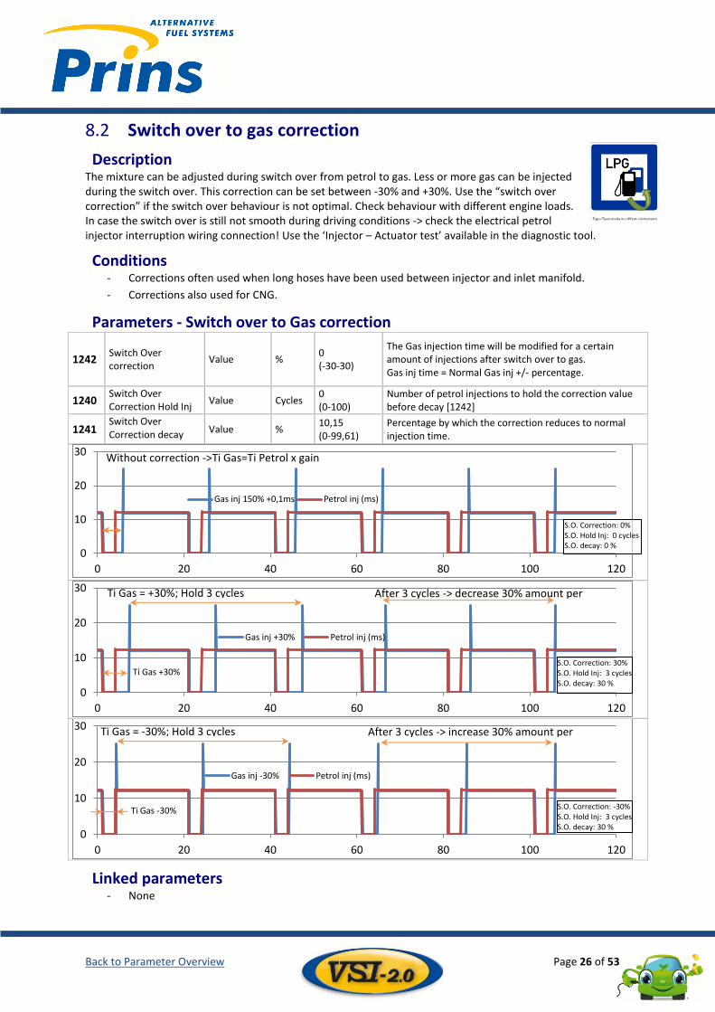
Switch over to gas correction 8.2
Description The mixture can be adjusted during switch over from petrol to gas. Less or more gas can be injected during the switch over. This correction can be set between -30% and +30%. Use the “switch over correction” if the switch over behaviour is not optimal. Check behaviour with different engine loads. In case the switch over is still not smooth during driving conditions -> check the electrical petrol injector interruption wiring connection! Use the ‘Injector – Actuator test’ available in the diagnostic tool.
Conditions - Corrections often used when long hoses have been used between injector and inlet manifold.
- Corrections also used for CNG.
Parameters - Switch over to Gas correction
1242 Switch Over correction
Value % 0 (-30-30)
The Gas injection time will be modified for a certain amount of injections after switch over to gas. Gas inj time = Normal Gas inj +/- percentage.
1240 Switch Over Correction Hold Inj
Value Cycles 0 (0-100)
Number of petrol injections to hold the correction value before decay [1242]
1241 Switch Over Correction decay Value %
10,15 (0-99,61)
Percentage by which the correction reduces to normal injection time.
Linked parameters - None
0
10
20
30
0 20 40 60 80 100 120
Gas inj 150% +0,1ms Petrol inj (ms)
0
10
20
30
0 20 40 60 80 100 120
Gas inj +30% Petrol inj (ms)
S.O. Correction: 30% S.O. Hold Inj: 3 cycles S.O. decay: 30 %
Ti Gas +30%
0
10
20
30
0 20 40 60 80 100 120
Gas inj -30% Petrol inj (ms)
S.O. Correction: -30% S.O. Hold Inj: 3 cycles S.O. decay: 30 %
Ti Gas -30%
After 3 cycles -> decrease 30% amount per injection
Ti Gas = +30%; Hold 3 cycles
Without correction ->Ti Gas=Ti Petrol x gain +offset
Ti Gas = -30%; Hold 3 cycles After 3 cycles -> increase 30% amount per injection
S.O. Correction: 0% S.O. Hold Inj: 0 cycles S.O. decay: 0 %
Back to Parameter Overview Page 27 of 53
9 Switch back to Petrol Switch back to petrol strategy ........................................................................................................................ 27 9.1
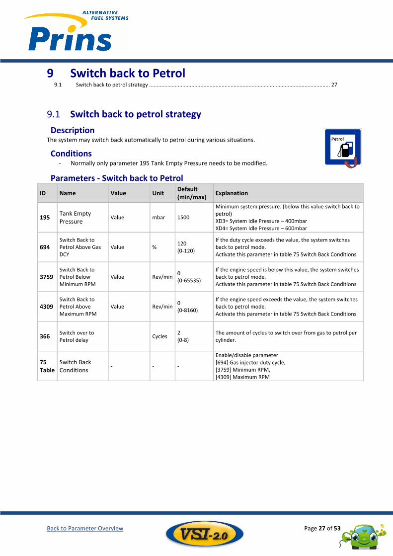
Switch back to petrol strategy 9.1
Description The system may switch back automatically to petrol during various situations.
Conditions - Normally only parameter 195 Tank Empty Pressure needs to be modified.
Parameters - Switch back to Petrol
ID Name Value Unit Default (min/max)
Explanation
195 Tank Empty Pressure
Value mbar 1500
Minimum system pressure. (below this value switch back to petrol) XD3= System Idle Pressure – 400mbar XD4= System Idle Pressure – 600mbar
694 Switch Back to Petrol Above Gas DCY
Value % 120 (0-120)
If the duty cycle exceeds the value, the system switches back to petrol mode. Activate this parameter in table 75 Switch Back Conditions
3759 Switch Back to Petrol Below Minimum RPM
Value Rev/min 0 (0-65535)
If the engine speed is below this value, the system switches back to petrol mode. Activate this parameter in table 75 Switch Back Conditions
4309 Switch Back to Petrol Above Maximum RPM
Value Rev/min 0 (0-8160)
If the engine speed exceeds the value, the system switches back to petrol mode. Activate this parameter in table 75 Switch Back Conditions
366 Switch over to Petrol delay
Cycles 2 (0-8)
The amount of cycles to switch over from gas to petrol per cylinder.
75 Table
Switch Back Conditions
- - -
Enable/disable parameter [694] Gas injector duty cycle, [3759] Minimum RPM, [4309] Maximum RPM
Back to Parameter Overview Page 28 of 53
Linked parameters AFC Management Engine Mixture Switch to Gas Switch to Petrol Regulator Tank Switch Service/ValveCare
Gas injector Gas injector Gas injector
1335 Gas Injector 226 Gain 694 Switch Back to Petrol Above Gas DCY
230 Offset
15169 Split fuel Gas DCY
Table 64 Open Loop Table
RPM RPM RPM
924 RPM Signal Source
61 Switch over RPM
4309 Switch Back to Petrol Above Maximum RPM
619 RPM Trigger Level
3759 Switch Back to Petrol Below Minimum RPM
297 RPM Factor
Gas Pressure Gas Pressure
195 Tank Empty Pressure
2223 System Pressure Sensor
Back to Parameter Overview Page 29 of 53
10 Regulator Solenoid valve(s) ............................................................................................................................................. 29 10.1
Gas Pressure / temperature sensor ................................................................................................................ 30 10.2
Evaporator Coolant Temperature (ECT) .......................................................................................................... 31 10.3
MAP Regulator ................................................................................................................................................ 32 10.4
Master / Slave ................................................................................................................................................. 33 10.5
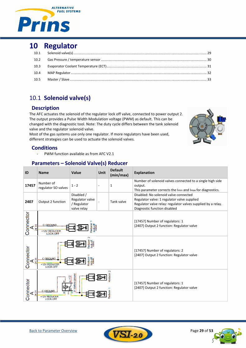
Solenoid valve(s) 10.1
Description The AFC actuates the solenoid of the regulator lock off valve, connected to power output 2. The output provides a Pulse Width Modulation voltage (PWM) as default. This can be changed with the diagnostic tool. Note: The duty cycle differs between the tank solenoid valve and the regulator solenoid valve. Most of the gas systems use only one regulator. If more regulators have been used, different strategies can be used to actuate the solenoid valves.
Conditions - PWM function available as from AFC V2.1
Parameters – Solenoid Valve(s) Reducer
ID Name Value Unit Default (min/max)
Explanation
17457 Number of regulator SO valves
1 - 2 - 1 Number of solenoid valves connected to a single high side output. This parameter corrects the Imin and Imax for diagnostics.
2407 Output 2 function
Disabled / Regulator valve / Regulator valve relay
- Tank valve
Disabled: No solenoid valve connected Regulator valve: 1 regulator valve supplied Regulator valve relay: regulator valves supplied by a relay. Diagnostic function disabled
[17457] Number of regulators: 1 [2407] Output 2 function: Regulator valve
[17457] Number of regulators: 2 [2407] Output 2 function: Regulator valve
[17457] Number of regulators: 1 [2407] Output 2 function: Regulator valve
Back to Parameter Overview Page 30 of 53
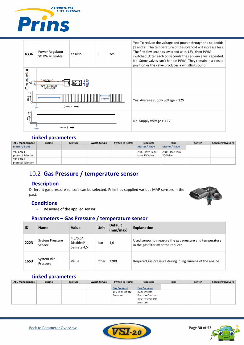
4336 Power Regulator SO PWM Enable
Yes/No - Yes
Yes: To reduce the voltage and power through the solenoids [1 and 2]. The temperature of the solenoid will increase less. The first few seconds switched with 12V, then PWM switched. After each 60 seconds the sequence will repeated. No: Some valves can’t handle PWM. They remain in a closed position or the valve produces a whistling sound.
Yes: Average supply voltage < 12V
No: Supply voltage > 12V
Linked parameters AFC Management Engine Mixture Switch to Gas Switch to Petrol Regulator Tank Switch Service/ValveCare
Master / Slave
Master / Slave Master / Slave
990 CAN 1 protocol Selection
2589 Slave Regu-lator SO Valve
2588 Slave Tank SO Valve
996 CAN 2 protocol Selection
Gas Pressure / temperature sensor 10.2
Description Different gas pressure sensors can be selected. Prins has supplied various MAP sensors in the past.
Conditions - Be aware of the applied sensor.
Parameters – Gas Pressure / temperature sensor
ID Name Value Unit Default (min/max)
Explanation
2223 System Pressure Sensor
4,0/5,5/ Disabled/ Sensata 4,5
bar 4,0 Used sensor to measure the gas pressure and temperature in the gas filter after the reducer.
1653 System Idle Pressure
Value mbar 2200 Required gas pressure during idling running of the engine.
Linked parameters AFC Management Engine Mixture Switch to Gas Switch to Petrol Regulator Tank Switch Service/ValveCare
Gas Pressure Gas Pressure
195 Tank Empty Pressure
2223 System Pressure Sensor
1653 System Idle pressure
Back to Parameter Overview Page 31 of 53
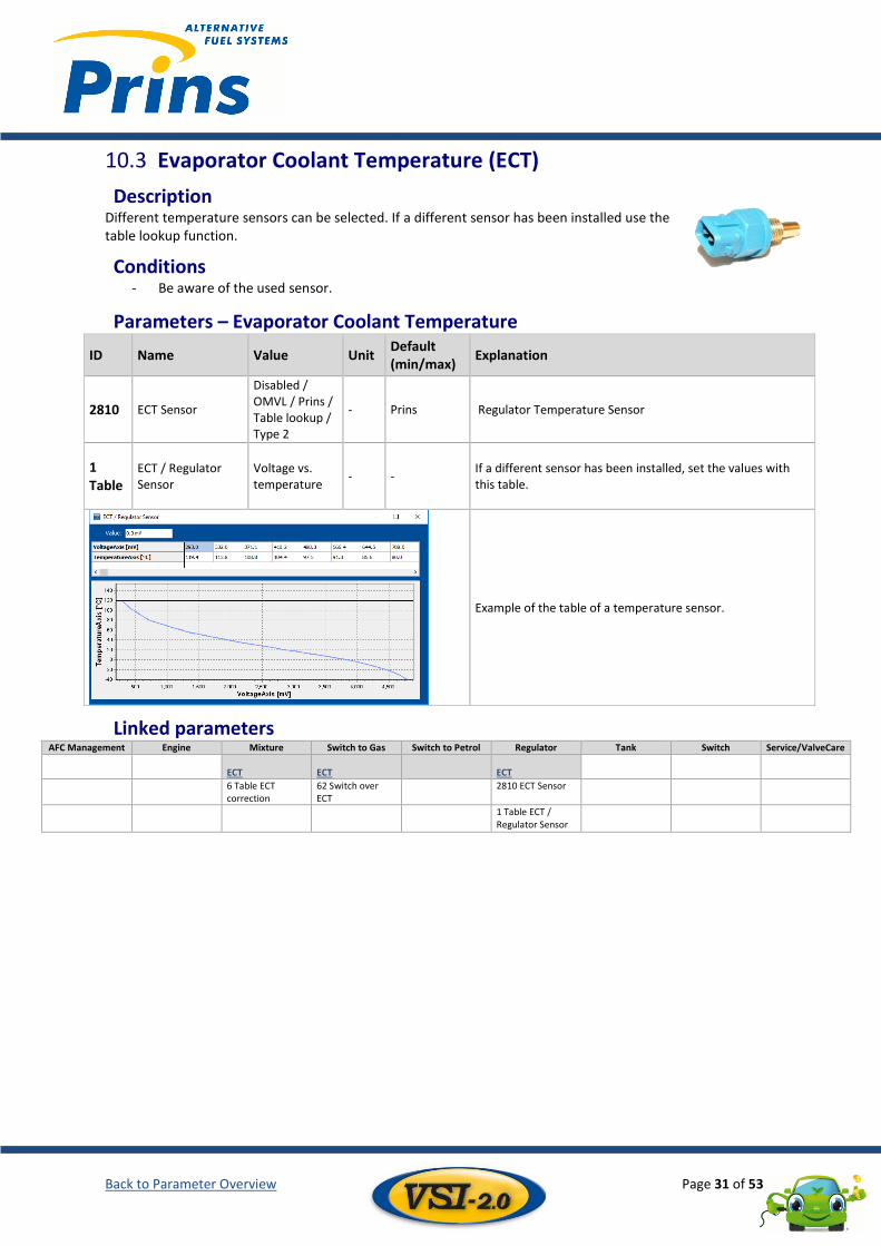
Evaporator Coolant Temperature (ECT) 10.3
Description Different temperature sensors can be selected. If a different sensor has been installed use the table lookup function.
Conditions - Be aware of the used sensor.
Parameters – Evaporator Coolant Temperature
ID Name Value Unit Default (min/max)
Explanation
2810 ECT Sensor
Disabled / OMVL / Prins / Table lookup / Type 2
- Prins Regulator Temperature Sensor
1 Table
ECT / Regulator Sensor
Voltage vs. temperature
- - If a different sensor has been installed, set the values with this table.
Example of the table of a temperature sensor.
Linked parameters AFC Management Engine Mixture Switch to Gas Switch to Petrol Regulator Tank Switch Service/ValveCare
ECT ECT
ECT
6 Table ECT correction
62 Switch over ECT
2810 ECT Sensor
1 Table ECT / Regulator Sensor
Back to Parameter Overview Page 32 of 53
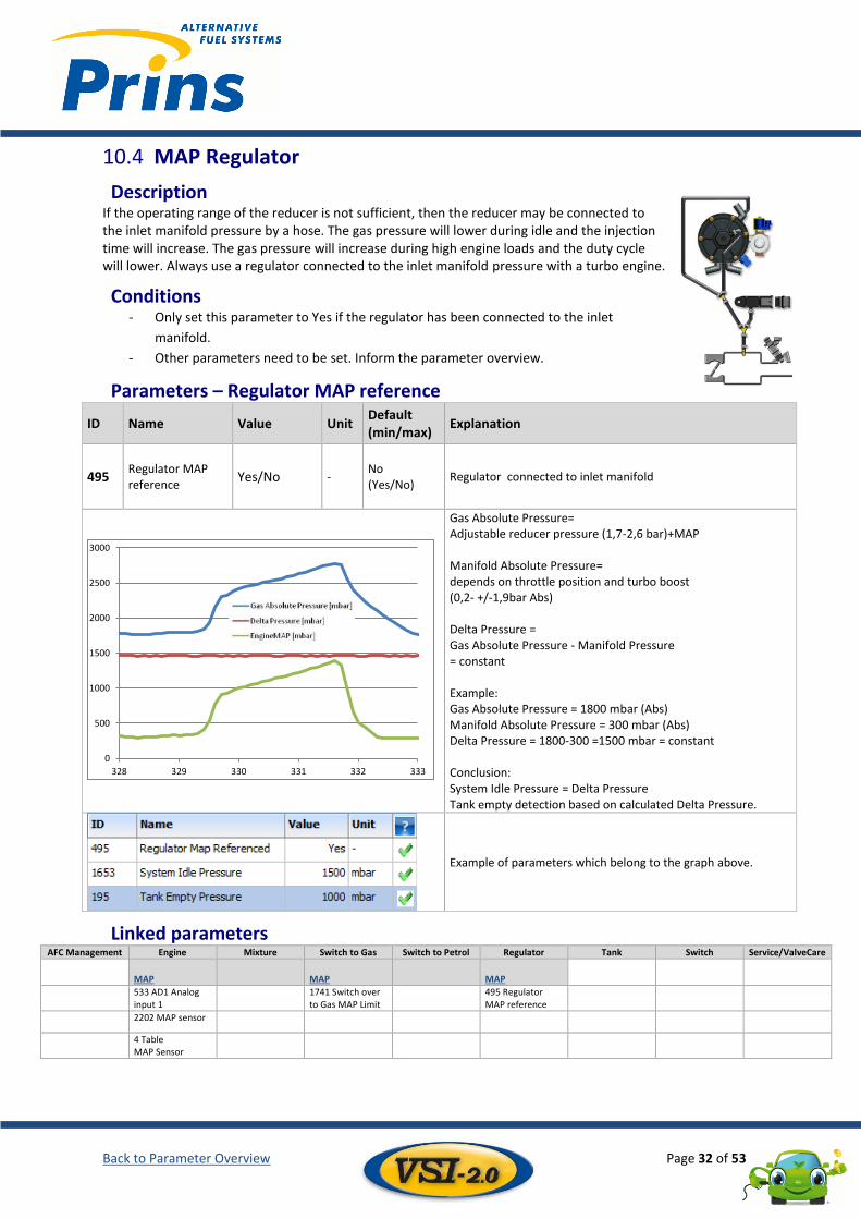
MAP Regulator 10.4
Description If the operating range of the reducer is not sufficient, then the reducer may be connected to the inlet manifold pressure by a hose. The gas pressure will lower during idle and the injection time will increase. The gas pressure will increase during high engine loads and the duty cycle will lower. Always use a regulator connected to the inlet manifold pressure with a turbo engine.
Conditions - Only set this parameter to Yes if the regulator has been connected to the inlet
manifold.
- Other parameters need to be set. Inform the parameter overview.
Parameters – Regulator MAP reference
ID Name Value Unit Default (min/max)
Explanation
495 Regulator MAP reference
Yes/No - No (Yes/No)
Regulator connected to inlet manifold
Gas Absolute Pressure= Adjustable reducer pressure (1,7-2,6 bar)+MAP Manifold Absolute Pressure= depends on throttle position and turbo boost (0,2- +/-1,9bar Abs) Delta Pressure = Gas Absolute Pressure - Manifold Pressure = constant Example: Gas Absolute Pressure = 1800 mbar (Abs) Manifold Absolute Pressure = 300 mbar (Abs) Delta Pressure = 1800-300 =1500 mbar = constant Conclusion: System Idle Pressure = Delta Pressure Tank empty detection based on calculated Delta Pressure.
Example of parameters which belong to the graph above.
Linked parameters AFC Management Engine Mixture Switch to Gas Switch to Petrol Regulator Tank Switch Service/ValveCare
MAP MAP MAP
533 AD1 Analog input 1
1741 Switch over to Gas MAP Limit
495 Regulator MAP reference
2202 MAP sensor
4 Table MAP Sensor
0
500
1000
1500
2000
2500
3000
328 329 330 331 332 333
Back to Parameter Overview Page 33 of 53
Master / Slave 10.5
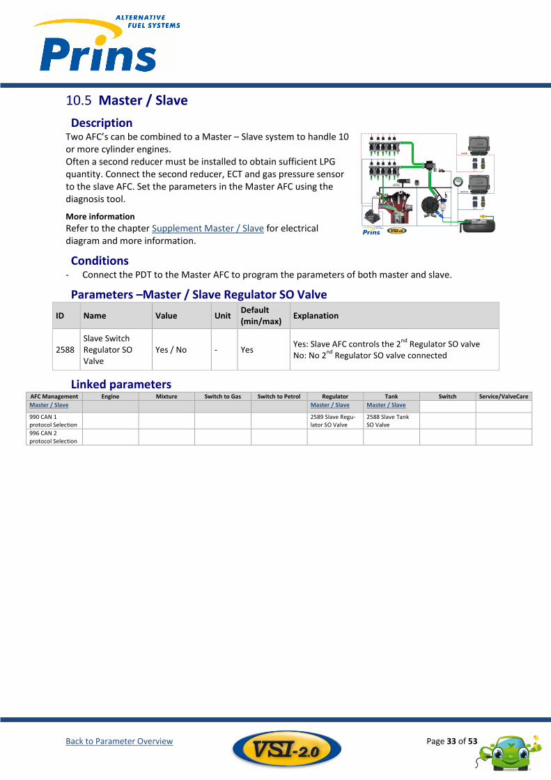
Description Two AFC’s can be combined to a Master – Slave system to handle 10 or more cylinder engines. Often a second reducer must be installed to obtain sufficient LPG quantity. Connect the second reducer, ECT and gas pressure sensor to the slave AFC. Set the parameters in the Master AFC using the diagnosis tool.
More information
Refer to the chapter Supplement Master / Slave for electrical diagram and more information.
Conditions - Connect the PDT to the Master AFC to program the parameters of both master and slave.
Parameters –Master / Slave Regulator SO Valve
ID Name Value Unit Default (min/max)
Explanation
2588 Slave Switch Regulator SO Valve
Yes / No - Yes Yes: Slave AFC controls the 2
nd Regulator SO valve
No: No 2nd
Regulator SO valve connected
Linked parameters AFC Management Engine Mixture Switch to Gas Switch to Petrol Regulator Tank Switch Service/ValveCare
Master / Slave
Master / Slave Master / Slave
990 CAN 1 protocol Selection
2589 Slave Regu-lator SO Valve
2588 Slave Tank SO Valve
996 CAN 2 protocol Selection
Back to Parameter Overview Page 34 of 53
11 Tank Solenoid Valve(s) ............................................................................................................................................. 34 11.1
Tank Level Sensor............................................................................................................................................ 35 11.2
Multiple Tank Function ................................................................................................................................... 37 11.3
Master / Slave ................................................................................................................................................. 40 11.4
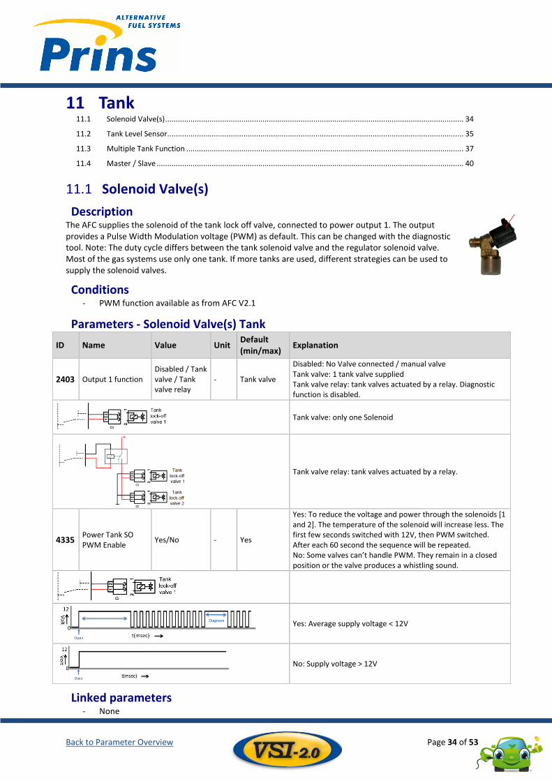
Solenoid Valve(s) 11.1
Description The AFC supplies the solenoid of the tank lock off valve, connected to power output 1. The output provides a Pulse Width Modulation voltage (PWM) as default. This can be changed with the diagnostic tool. Note: The duty cycle differs between the tank solenoid valve and the regulator solenoid valve. Most of the gas systems use only one tank. If more tanks are used, different strategies can be used to supply the solenoid valves.
Conditions - PWM function available as from AFC V2.1
Parameters - Solenoid Valve(s) Tank
ID Name Value Unit Default (min/max)
Explanation
2403 Output 1 function Disabled / Tank valve / Tank valve relay
- Tank valve
Disabled: No Valve connected / manual valve Tank valve: 1 tank valve supplied Tank valve relay: tank valves actuated by a relay. Diagnostic function is disabled.
Tank valve: only one Solenoid
Tank valve relay: tank valves actuated by a relay.
4335 Power Tank SO PWM Enable
Yes/No - Yes
Yes: To reduce the voltage and power through the solenoids [1 and 2]. The temperature of the solenoid will increase less. The first few seconds switched with 12V, then PWM switched. After each 60 second the sequence will be repeated. No: Some valves can’t handle PWM. They remain in a closed position or the valve produces a whistling sound.
Yes: Average supply voltage < 12V
No: Supply voltage > 12V
Linked parameters - None
Back to Parameter Overview Page 35 of 53
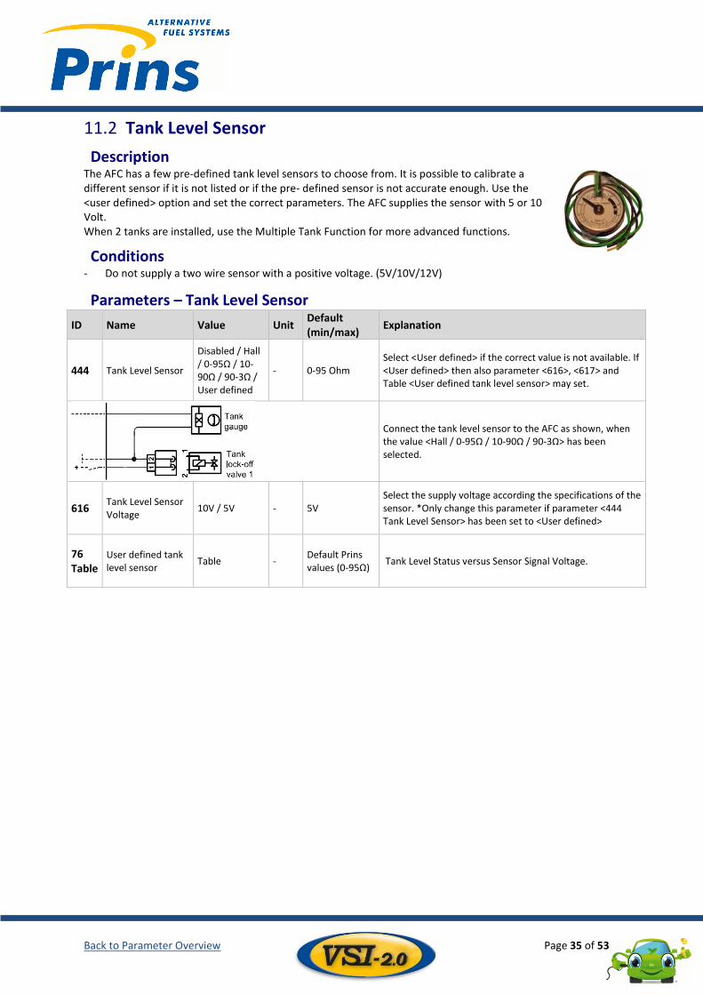
Tank Level Sensor 11.2
Description The AFC has a few pre-defined tank level sensors to choose from. It is possible to calibrate a different sensor if it is not listed or if the pre- defined sensor is not accurate enough. Use the <user defined> option and set the correct parameters. The AFC supplies the sensor with 5 or 10 Volt. When 2 tanks are installed, use the Multiple Tank Function for more advanced functions.
Conditions - Do not supply a two wire sensor with a positive voltage. (5V/10V/12V)
Parameters – Tank Level Sensor
ID Name Value Unit Default (min/max)
Explanation
444 Tank Level Sensor
Disabled / Hall / 0-95Ω / 10-90Ω / 90-3Ω / User defined
- 0-95 Ohm Select <User defined> if the correct value is not available. If <User defined> then also parameter <616>, <617> and Table <User defined tank level sensor> may set.
Connect the tank level sensor to the AFC as shown, when the value <Hall / 0-95Ω / 10-90Ω / 90-3Ω> has been selected.
616 Tank Level Sensor Voltage
10V / 5V - 5V Select the supply voltage according the specifications of the sensor. *Only change this parameter if parameter <444 Tank Level Sensor> has been set to <User defined>
76 Table
User defined tank level sensor
Table - Default Prins values (0-95Ω)
Tank Level Status versus Sensor Signal Voltage.
Back to Parameter Overview Page 36 of 53
ID Name Value Unit Default (min/max)
Explanation
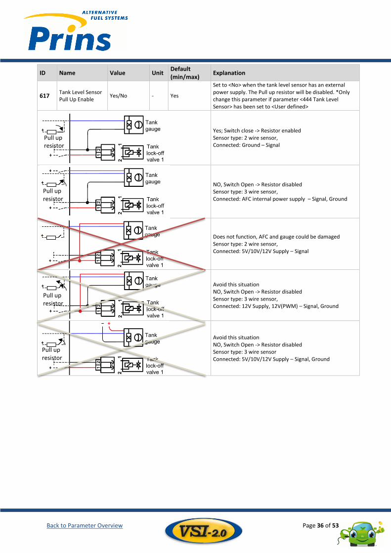
617 Tank Level Sensor Pull Up Enable
Yes/No - Yes
Set to <No> when the tank level sensor has an external power supply. The Pull up resistor will be disabled. *Only change this parameter if parameter <444 Tank Level Sensor> has been set to <User defined>
Yes; Switch close -> Resistor enabled Sensor type: 2 wire sensor, Connected: Ground – Signal
NO, Switch Open -> Resistor disabled Sensor type: 3 wire sensor, Connected: AFC internal power supply – Signal, Ground
Does not function, AFC and gauge could be damaged Sensor type: 2 wire sensor, Connected: 5V/10V/12V Supply – Signal
Avoid this situation NO, Switch Open -> Resistor disabled Sensor type: 3 wire sensor, Connected: 12V Supply, 12V(PWM) – Signal, Ground
Avoid this situation NO, Switch Open -> Resistor disabled Sensor type: 3 wire sensor Connected: 5V/10V/12V Supply – Signal, Ground
Pull up resistor
Pull up resistor
Pull up resistor
Pull up resistor
Back to Parameter Overview Page 37 of 53
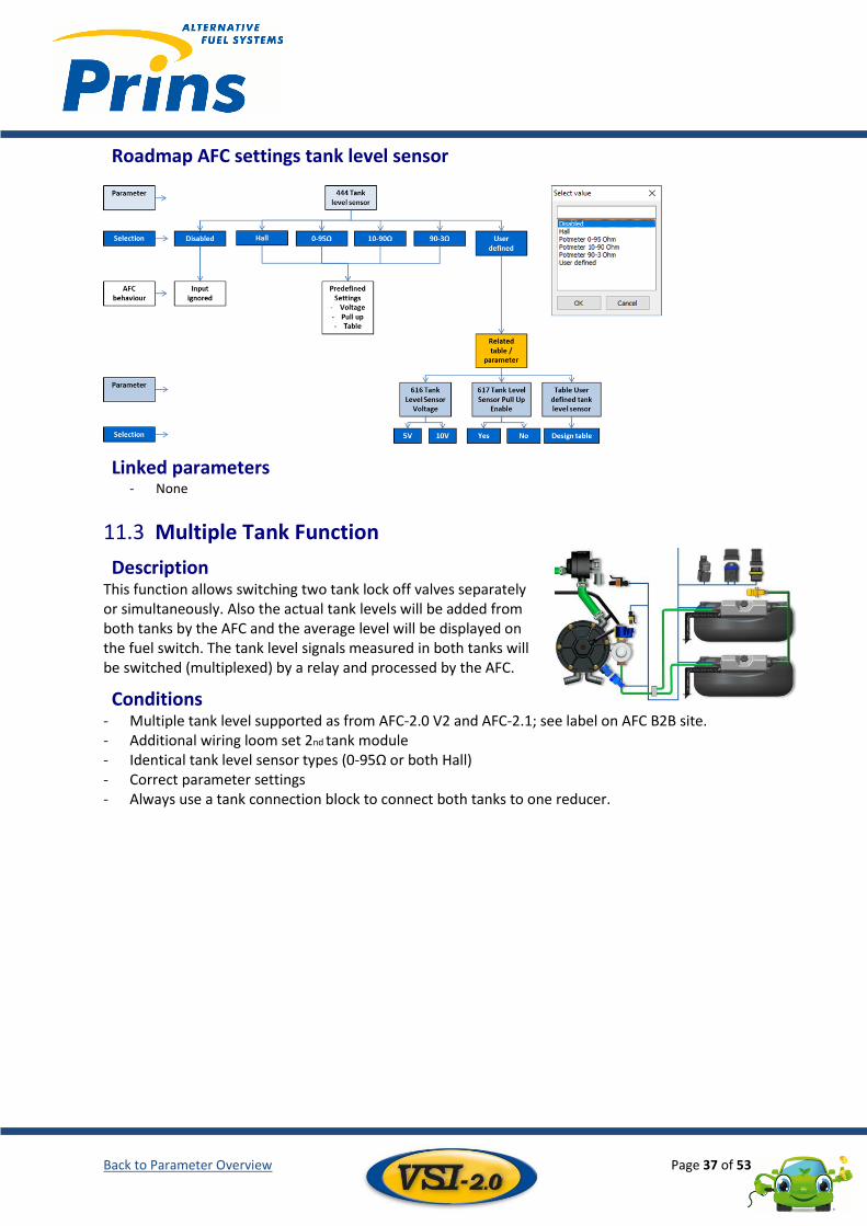
Roadmap AFC settings tank level sensor
Linked parameters - None
Multiple Tank Function 11.3
Description This function allows switching two tank lock off valves separately or simultaneously. Also the actual tank levels will be added from both tanks by the AFC and the average level will be displayed on the fuel switch. The tank level signals measured in both tanks will be switched (multiplexed) by a relay and processed by the AFC.
Conditions - Multiple tank level supported as from AFC-2.0 V2 and AFC-2.1; see label on AFC B2B site. - Additional wiring loom set 2nd tank module - Identical tank level sensor types (0-95Ω or both Hall) - Correct parameter settings - Always use a tank connection block to connect both tanks to one reducer.
Back to Parameter Overview Page 38 of 53
Parameters - Multiple Tank Function
ID Name Value Unit Default (min/max)
Explanation
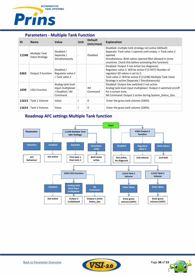
11248 Multiple Tank Valve Strategy
Disabled / Separate / Simultaneously
- Disabled
Disabled: multiple tank strategy not active (default) Separate: Tank valve 1 opened until empty -> Tank valve 2 opened. Simultaneous: Both valves opened (Not allowed in some countries. Check this before activating this function)
6363 Output 3 function Disabled / Regulator valve 2 / Tank valve 2
Disabled: Output 3 not active (no diagnosis) Regulator valve 2: Will be active if [17457] Number of regulator SO valves is set to 2. Tank valve 2: Will be active if [11248] Multiple Tank Valve Strategy is active (Separate / Simultaneously)
1039 LSS2 Function
Analog tank level input multiplexer / Disabled / IM Command
- IM Command
Disabled: Output low switched 2 not active. Analog tank level input multiplexer: Output 2 switched on/off for a certain time. IM Command: Output 2 active during System_Status_Gas.
11613 Tank 1 Volume Value l 0 Enter the gross tank volume (100%)
11614 Tank 2 Volume Value l 0 Enter the gross tank volume (100%)
Roadmap AFC settings Multiple Tank function
Back to Parameter Overview Page 39 of 53
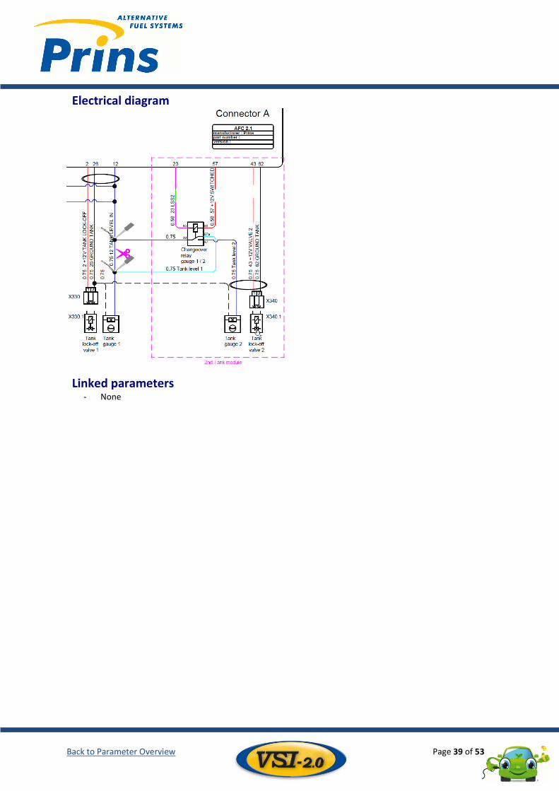
Electrical diagram
Linked parameters - None
Back to Parameter Overview Page 40 of 53
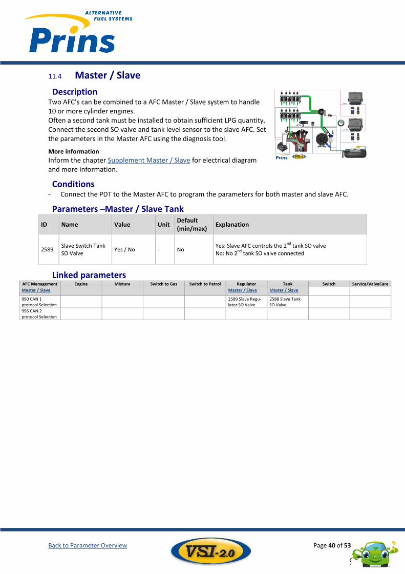
Master / Slave 11.4
Description Two AFC’s can be combined to a AFC Master / Slave system to handle 10 or more cylinder engines. Often a second tank must be installed to obtain sufficient LPG quantity. Connect the second SO valve and tank level sensor to the slave AFC. Set the parameters in the Master AFC using the diagnosis tool.
More information
Inform the chapter Supplement Master / Slave for electrical diagram and more information.
Conditions - Connect the PDT to the Master AFC to program the parameters for both master and slave AFC.
Parameters –Master / Slave Tank
ID Name Value Unit Default (min/max)
Explanation
2589 Slave Switch Tank SO Valve
Yes / No - No Yes: Slave AFC controls the 2
nd tank SO valve
No: No 2nd
tank SO valve connected
Linked parameters AFC Management Engine Mixture Switch to Gas Switch to Petrol Regulator Tank Switch Service/ValveCare
Master / Slave
Master / Slave Master / Slave
990 CAN 1 protocol Selection
2589 Slave Regu-lator SO Valve
2588 Slave Tank SO Valve
996 CAN 2 protocol Selection
Back to Parameter Overview Page 41 of 53
12 Switch Tank level indicator ......................................................................................................................................... 41 12.1
Fuel Status LED ................................................................................................................................................ 42 12.2
Switch Strategy ............................................................................................................................................... 42 12.3
Daylight Correction ......................................................................................................................................... 43 12.4
Beeper ............................................................................................................................................................. 43 12.5
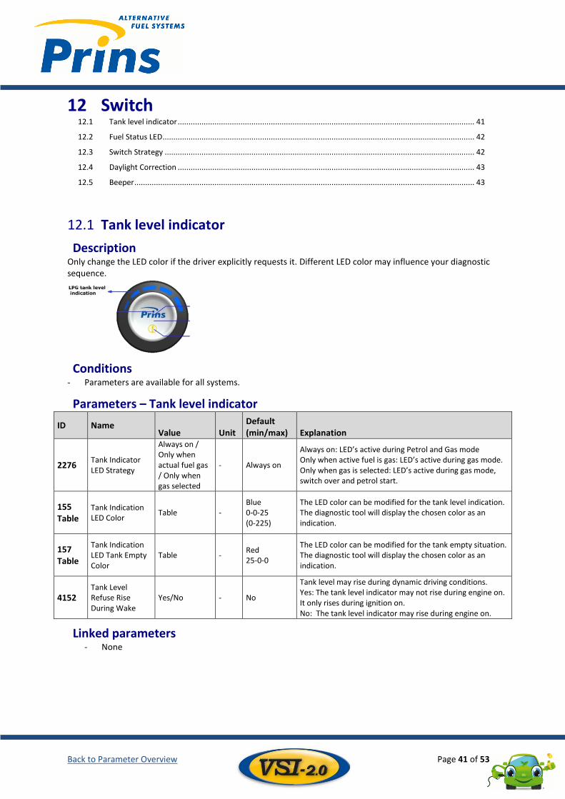
Tank level indicator 12.1
Description Only change the LED color if the driver explicitly requests it. Different LED color may influence your diagnostic sequence.
Conditions - Parameters are available for all systems.
Parameters – Tank level indicator
ID Name Value Unit
Default (min/max) Explanation
2276 Tank Indicator LED Strategy
Always on / Only when actual fuel gas / Only when gas selected
- Always on
Always on: LED’s active during Petrol and Gas mode Only when active fuel is gas: LED’s active during gas mode. Only when gas is selected: LED’s active during gas mode, switch over and petrol start.
155 Table
Tank Indication LED Color
Table - Blue 0-0-25 (0-225)
The LED color can be modified for the tank level indication. The diagnostic tool will display the chosen color as an indication.
157 Table
Tank Indication LED Tank Empty Color
Table - Red 25-0-0
The LED color can be modified for the tank empty situation. The diagnostic tool will display the chosen color as an indication.
4152 Tank Level Refuse Rise During Wake
Yes/No - No
Tank level may rise during dynamic driving conditions. Yes: The tank level indicator may not rise during engine on. It only rises during ignition on. No: The tank level indicator may rise during engine on.
Linked parameters - None

Back to Parameter Overview Page 42 of 53
Fuel Status LED 12.2
Description Only change the LED color if the driver explicitly requests it. Different LED color may influence diagnostics.
Conditions - Parameters are available for all systems.
Parameters – Fuel Status LED
ID Name Value Unit
Default (min/max) Explanation
2273 Fuel Status LED Strategy
Active during gas operation / Based on selected fuel
- Active during gas operation
Active During Gas: LED only active when driving in gas mode. Based on selected fuel: Gas or Petrol status will be shown by the Fuel Status LED. The petrol color LED may be changed by using Table "Fuel Status LED Master Fuel Color.
158 Table
Fuel Status LED Color (Gas)
Table - 25-25-25 (0-225)
The LED color can be modified for gas mode. The diagnostic tool will display the chosen color as an indication.
159 Table
Fuel Status LED Master Fuel Color
Table - 0-0-0 (0-225)
The LED color can be modified for petrol mode. The diagnostic tool will display the chosen color as an indication.
Linked parameters - None
Switch Strategy 12.3
Description Only change the LED color if the driver explicitly requests it. Different LED color may influence diagnostics.
Conditions - Parameters are available for all systems.
Parameters – Switch Strategy
ID Name Value Unit
Default (min/max) Explanation
2629 Switch Blink During Gas Not Allowed
Yes/No No The Switch can display a gas not allowed situation.
3653 Switch Turn Off After Engine Off-Time
Value / 0 = disabed
s 0 (0-522,2)
The delay time that the switch stays illuminated after an engine stop.
Back to Parameter Overview Page 43 of 53
Linked parameters - None
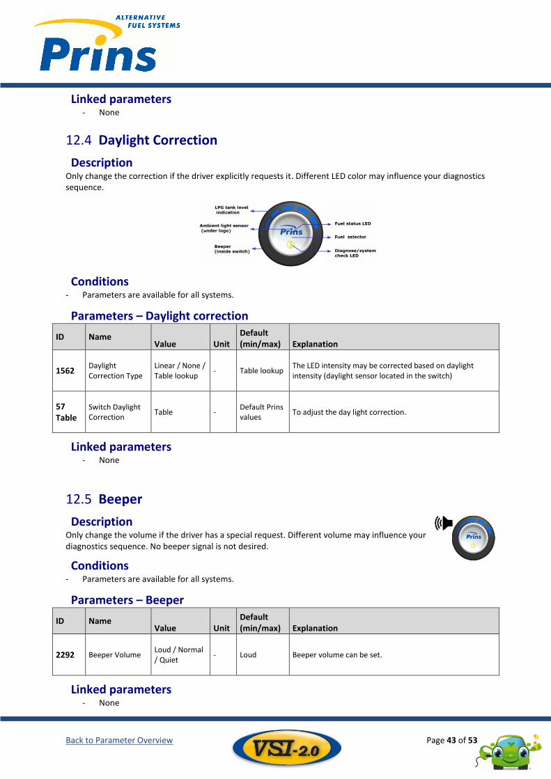
Daylight Correction 12.4
Description Only change the correction if the driver explicitly requests it. Different LED color may influence your diagnostics sequence.
Conditions - Parameters are available for all systems.
Parameters – Daylight correction
ID Name Value Unit
Default (min/max) Explanation
1562 Daylight Correction Type
Linear / None / Table lookup
- Table lookup The LED intensity may be corrected based on daylight intensity (daylight sensor located in the switch)
57 Table
Switch Daylight Correction
Table - Default Prins values
To adjust the day light correction.
Linked parameters - None
Beeper 12.5
Description Only change the volume if the driver has a special request. Different volume may influence your diagnostics sequence. No beeper signal is not desired.
Conditions - Parameters are available for all systems.
Parameters – Beeper
ID Name Value Unit
Default (min/max) Explanation
2292 Beeper Volume Loud / Normal / Quiet
- Loud Beeper volume can be set.
Linked parameters - None
Back to Parameter Overview Page 44 of 53
13 Service / ValveCare Service ............................................................................................................................................................. 44 13.1
ValveCare ........................................................................................................................................................ 45 13.2
Critical Trouble codes...................................................................................................................................... 46 13.3
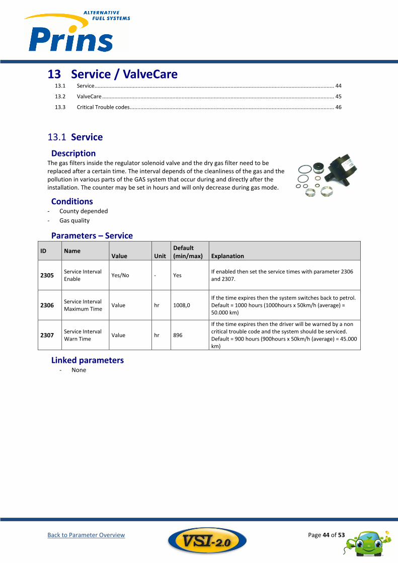
Service 13.1
Description The gas filters inside the regulator solenoid valve and the dry gas filter need to be replaced after a certain time. The interval depends of the cleanliness of the gas and the pollution in various parts of the GAS system that occur during and directly after the installation. The counter may be set in hours and will only decrease during gas mode.
Conditions - County depended
- Gas quality
Parameters – Service
ID Name Value Unit
Default (min/max) Explanation
2305 Service Interval Enable
Yes/No - Yes If enabled then set the service times with parameter 2306 and 2307.
2306 Service Interval Maximum Time
Value hr 1008,0 If the time expires then the system switches back to petrol. Default = 1000 hours (1000hours x 50km/h (average) = 50.000 km)
2307 Service Interval Warn Time
Value hr 896
If the time expires then the driver will be warned by a non critical trouble code and the system should be serviced. Default = 900 hours (900hours x 50km/h (average) = 45.000 km)
Linked parameters - None
Back to Parameter Overview Page 45 of 53
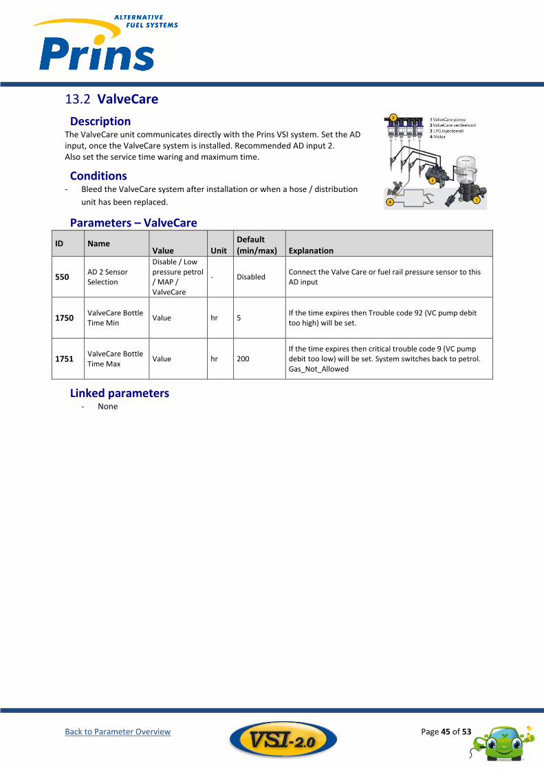
ValveCare 13.2
Description The ValveCare unit communicates directly with the Prins VSI system. Set the AD input, once the ValveCare system is installed. Recommended AD input 2. Also set the service time waring and maximum time.
Conditions - Bleed the ValveCare system after installation or when a hose / distribution
unit has been replaced.
Parameters – ValveCare
ID Name Value Unit
Default (min/max) Explanation
550 AD 2 Sensor Selection
Disable / Low pressure petrol / MAP / ValveCare
- Disabled Connect the Valve Care or fuel rail pressure sensor to this AD input
1750 ValveCare Bottle Time Min
Value hr 5 If the time expires then Trouble code 92 (VC pump debit too high) will be set.
1751 ValveCare Bottle Time Max
Value hr 200 If the time expires then critical trouble code 9 (VC pump debit too low) will be set. System switches back to petrol. Gas_Not_Allowed
Linked parameters - None
Back to Parameter Overview Page 46 of 53
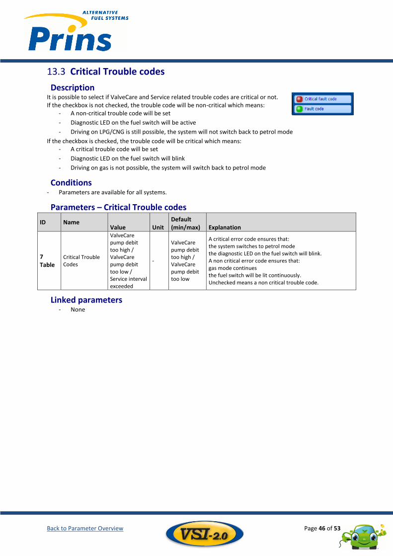
Critical Trouble codes 13.3
Description It is possible to select if ValveCare and Service related trouble codes are critical or not. If the checkbox is not checked, the trouble code will be non-critical which means:
- A non-critical trouble code will be set
- Diagnostic LED on the fuel switch will be active
- Driving on LPG/CNG is still possible, the system will not switch back to petrol mode
If the checkbox is checked, the trouble code will be critical which means: - A critical trouble code will be set
- Diagnostic LED on the fuel switch will blink
- Driving on gas is not possible, the system will switch back to petrol mode
Conditions - Parameters are available for all systems.
Parameters – Critical Trouble codes
ID Name Value Unit
Default (min/max) Explanation
7 Table
Critical Trouble Codes
ValveCare pump debit too high / ValveCare pump debit too low / Service interval exceeded
-
ValveCare pump debit too high / ValveCare pump debit too low
A critical error code ensures that: the system switches to petrol mode the diagnostic LED on the fuel switch will blink. A non critical error code ensures that: gas mode continues the fuel switch will be lit continuously. Unchecked means a non critical trouble code.
Linked parameters - None
Back to Parameter Overview Page 47 of 53
14 Supplement 14.1 Supplement Master / Slave ............................................................................................................................. 47
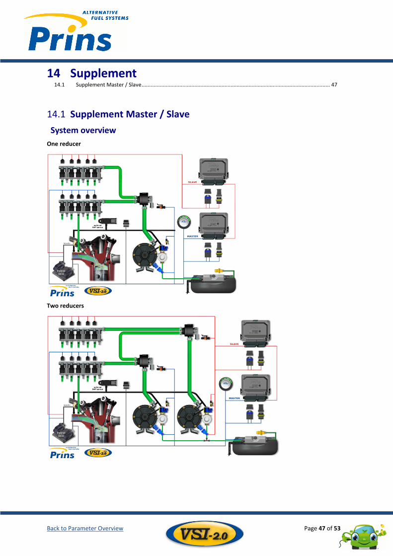
Supplement Master / Slave 14.1
System overview
One reducer
Two reducers
Back to Parameter Overview Page 48 of 53
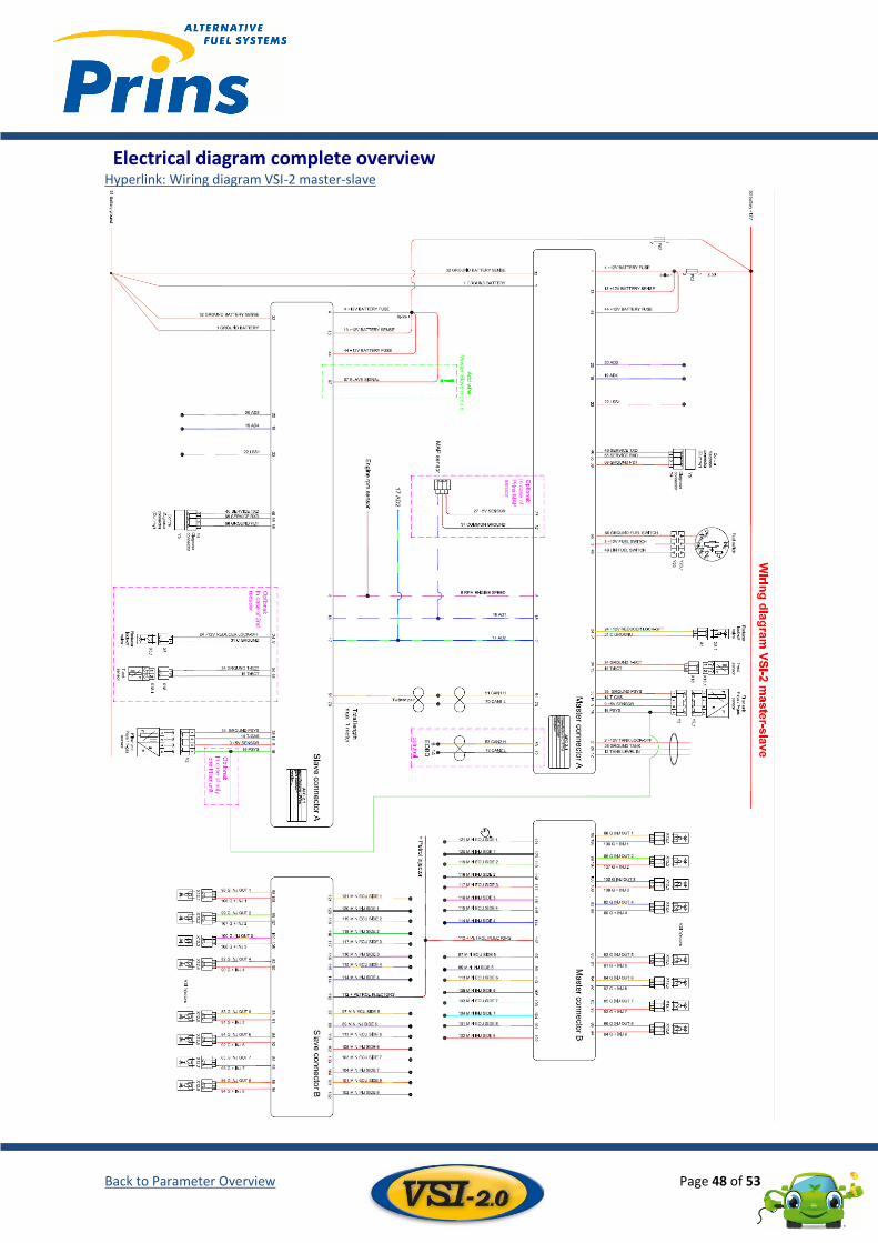
Electrical diagram complete overview Hyperlink: Wiring diagram VSI-2 master-slave
Back to Parameter Overview Page 49 of 53
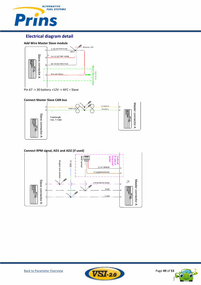
Electrical diagram detail
Add Wire Master Slave module
Pin 67 -> 30 battery +12V -> AFC = Slave
Connect Master Slave CAN bus
Connect RPM signal, AD1 and AD2 (if used)
Back to Parameter Overview Page 50 of 53
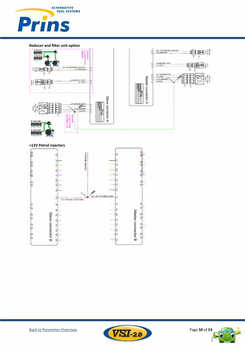
Reducer and filter unit option
+12V Petrol injectors
Back to Parameter Overview Page 51 of 53
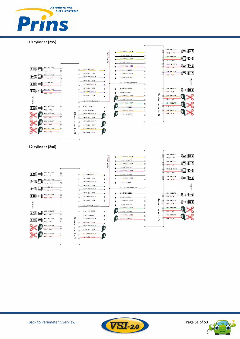
10 cylinder (2x5)
12 cylinder (2x6)
Back to Parameter Overview Page 52 of 53
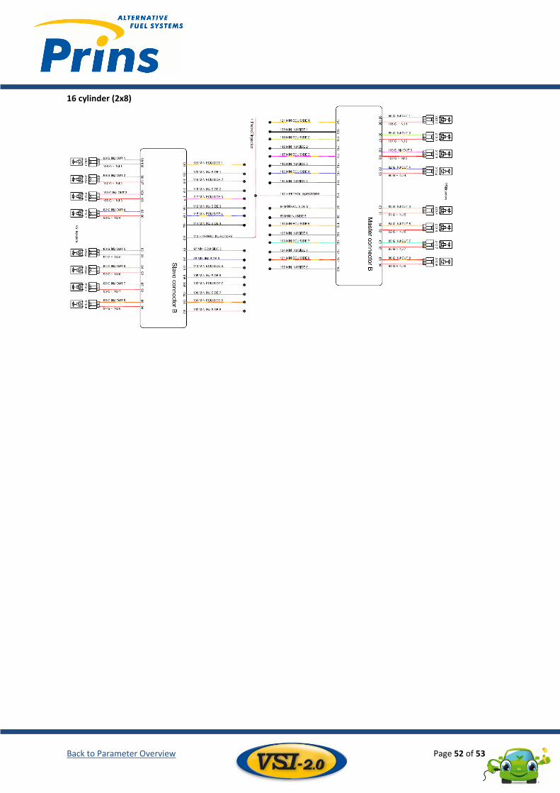
16 cylinder (2x8)
Back to Parameter Overview Page 53 of 53
This training manual was developed by Prins Autogassystemen B.V. © All rights reserved. No part of this publication may be reproduced or published without the permission of Prins Autogassystemen BV For more information: Prins Autogassystemen B.V. Jan Hilgersweg 22 5657 ES Eindhoven, the Netherlands Tel: (+31) 040-2547700 Fax: (+31) 040-2549749 www.prinsautogas.com [email protected]