Embed Size (px)
Citation preview
ASPRS 2008 Annual Conference Portland, Oregon April 28 - May 2, 2008
CALIBRATION OF CAMERA SYSTEMS
Karsten Jacobsen
Leibniz University Hannover Nienburger Str. 1
D-30167 Hannover, Germany [email protected]
ABSTRACT
Multiple camera systems including combinations of vertical and oblique images like used by Pictometry and Multivision are becoming popular very fast. The image combinations easily can be used for interpretation and also for metric purposes. In most cases the orientation is based on direct sensor orientation, using inertial measurement units and relative kinematic GPS-positioning. Usually this will be done not with the precision, possible for standard photogrammetric projects, but the geometric precision can be improved by satisfying system calibration. The system calibration includes the calibration of the sub-cameras and the geometric relation of the oblique sub-cameras to the vertical reference camera together with the boresite misalignment. Supported by the direct sensor orientation, also the inner orientation can be improved. The individual camera geometry can be determined by bundle block adjustment with self calibration. This allows also determination of the relation of the sub-cameras to each other. The procedure, computational steps, results and limitations are described.
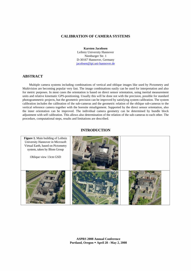
INTRODUCTION Figure 1. Main building of Leibniz University Hannover in Microsoft Virtual Earth, based on Pictometry
system, taken by Blom Group
Oblique view 13cm GSD
ASPRS 2008 Annual Conference Portland, Oregon April 28 - May 2, 2008
Images from the Pictometry system are widely used by Microsoft Virtual Earth (Figure 1). In Western Europe the Blom Group is imaging all cities with a population larger than 50000, that means approximately 900 cities with together approximately 100 000 km². 12 Pictometry camera systems are in use for this. The competitor MultiVision is also active in Europe and USA.
The commercial applications of the combination of vertical with oblique images like generated by Pictometry and MultiVision systems is dominated by visual inspections for public safety and planning purposes. The use together with geoinformation systems requires the knowledge of the exterior orientation of every image together with a digital elevation model (DEM). Block adjustments are too time-consuming and complex, so the exterior orientations are based on direct sensor orientation – the use of the combination of inertial measurement units (IMU) together with relative kinematic GPS-positioning. In several countries networks of permanent GPS reference stations are available, but also with satellite based reference systems like OMNISTAR and different off-line reference systems, like JPL Final, the GPS reference is available in sub-meter accuracy. Especially for planning purposes not only the visualization is important, also some metric information is used. This requires a calibration of the imaging system in relation to the IMU and the GPS-antenna.
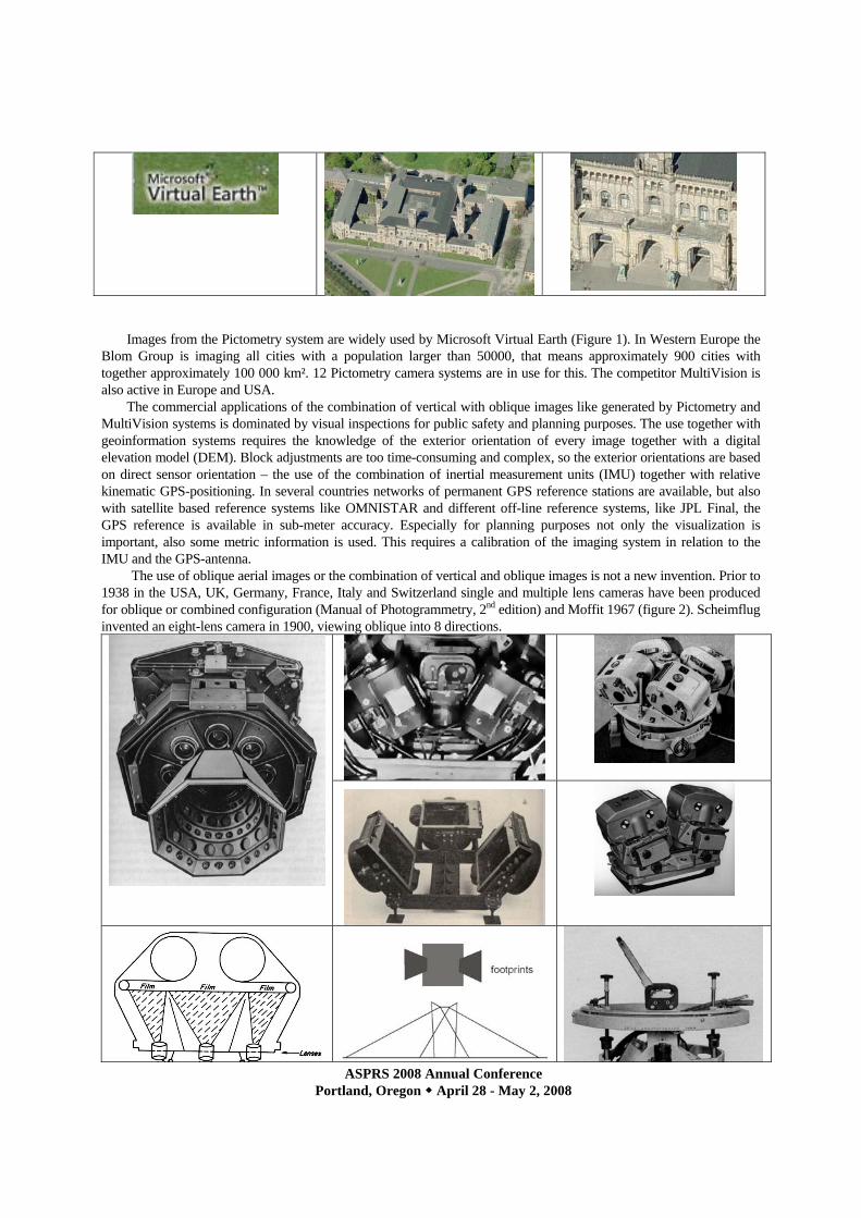
The use of oblique aerial images or the combination of vertical and oblique images is not a new invention. Prior to 1938 in the USA, UK, Germany, France, Italy and Switzerland single and multiple lens cameras have been produced for oblique or combined configuration (Manual of Photogrammetry, 2nd edition) and Moffit 1967 (figure 2). Scheimflug invented an eight-lens camera in 1900, viewing oblique into 8 directions.
ASPRS 2008 Annual Conference Portland, Oregon April 28 - May 2, 2008
left: Scheimpflug’s 8-lens camera (1900)
USGS 9-lens camera 3 above figures: Trimetrogon Zeiss oblique camera arrangements Figure 2. historic multiple lens and multiple camera arrangement for oblique aerial images
In military reconnaissance oblique images are in use since long time. They combine the advantage of a view to
facades and other vertical objects, together with imaging from distance. The orientation and calibration of such systems, partially with extreme long focal length, is known since longer time (Jacobsen 1988). Another application of the oblique view we have in line scanner cameras like Leica ADS40, DLR HRSC, Wehrli 3-DAS-1 and Jena Optronik JAS-150, viewing to the vertical direction, forward and backward. Even with standard size wide angle or super wide angle photographic cameras we can see the facades at the image side. At the center of the side of a super wide angle standard aerial camera with 85mm focal length the nadir angle is 53°, in the image corner even 62°, while we have nadir angles of the oblique cameras used by Pictometry and MultiVision of 45° up to 60°.
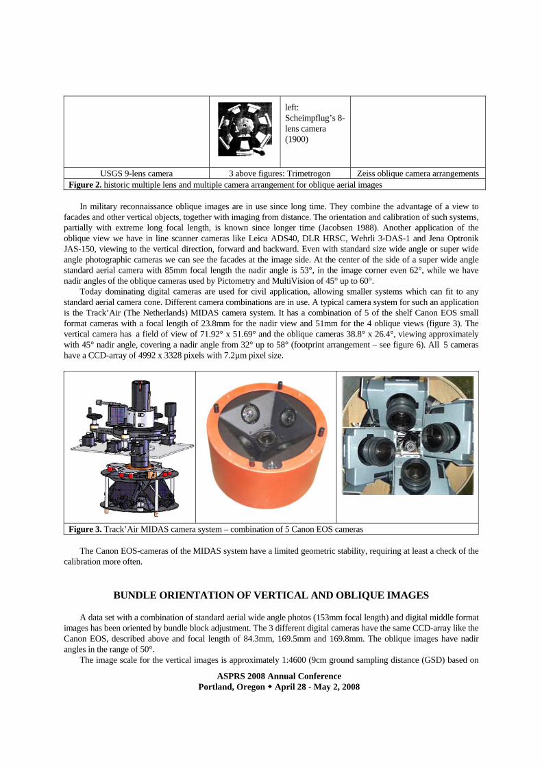
Today dominating digital cameras are used for civil application, allowing smaller systems which can fit to any standard aerial camera cone. Different camera combinations are in use. A typical camera system for such an application is the Track’Air (The Netherlands) MIDAS camera system. It has a combination of 5 of the shelf Canon EOS small format cameras with a focal length of 23.8mm for the nadir view and 51mm for the 4 oblique views (figure 3). The vertical camera has a field of view of 71.92° x 51.69° and the oblique cameras 38.8° x 26.4°, viewing approximately with 45° nadir angle, covering a nadir angle from 32° up to 58° (footprint arrangement – see figure 6). All 5 cameras have a CCD-array of 4992 x 3328 pixels with 7.2µm pixel size.
Figure 3. Track’Air MIDAS camera system – combination of 5 Canon EOS cameras The Canon EOS-cameras of the MIDAS system have a limited geometric stability, requiring at least a check of the
calibration more often.
BUNDLE ORIENTATION OF VERTICAL AND OBLIQUE IMAGES
A data set with a combination of standard aerial wide angle photos (153mm focal length) and digital middle format images has been oriented by bundle block adjustment. The 3 different digital cameras have the same CCD-array like the Canon EOS, described above and focal length of 84.3mm, 169.5mm and 169.8mm. The oblique images have nadir angles in the range of 50°.
The image scale for the vertical images is approximately 1:4600 (9cm ground sampling distance (GSD) based on
ASPRS 2008 Annual Conference Portland, Oregon April 28 - May 2, 2008
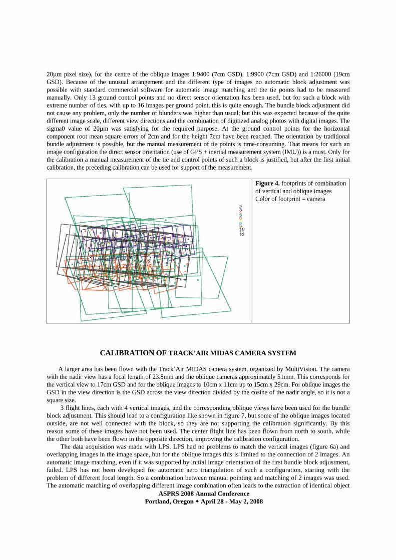
20µm pixel size), for the centre of the oblique images 1:9400 (7cm GSD), 1:9900 (7cm GSD) and 1:26000 (19cm GSD). Because of the unusual arrangement and the different type of images no automatic block adjustment was possible with standard commercial software for automatic image matching and the tie points had to be measured manually. Only 13 ground control points and no direct sensor orientation has been used, but for such a block with extreme number of ties, with up to 16 images per ground point, this is quite enough. The bundle block adjustment did not cause any problem, only the number of blunders was higher than usual; but this was expected because of the quite different image scale, different view directions and the combination of digitized analog photos with digital images. The sigma0 value of 20µm was satisfying for the required purpose. At the ground control points for the horizontal component root mean square errors of 2cm and for the height 7cm have been reached. The orientation by traditional bundle adjustment is possible, but the manual measurement of tie points is time-consuming. That means for such an image configuration the direct sensor orientation (use of GPS + inertial measurement system (IMU)) is a must. Only for the calibration a manual measurement of the tie and control points of such a block is justified, but after the first initial calibration, the preceding calibration can be used for support of the measurement.
Figure 4. footprints of combination of vertical and oblique images Color of footprint = camera
CALIBRATION OF TRACK’AIR MIDAS CAMERA SYSTEM A larger area has been flown with the Track’Air MIDAS camera system, organized by MultiVision. The camera
with the nadir view has a focal length of 23.8mm and the oblique cameras approximately 51mm. This corresponds for the vertical view to 17cm GSD and for the oblique images to 10cm x 11cm up to 15cm x 29cm. For oblique images the GSD in the view direction is the GSD across the view direction divided by the cosine of the nadir angle, so it is not a square size.
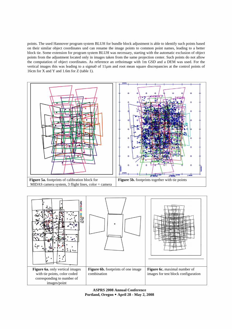
3 flight lines, each with 4 vertical images, and the corresponding oblique views have been used for the bundle block adjustment. This should lead to a configuration like shown in figure 7, but some of the oblique images located outside, are not well connected with the block, so they are not supporting the calibration significantly. By this reason some of these images have not been used. The center flight line has been flown from north to south, while the other both have been flown in the opposite direction, improving the calibration configuration.
The data acquisition was made with LPS. LPS had no problems to match the vertical images (figure 6a) and overlapping images in the image space, but for the oblique images this is limited to the connection of 2 images. An automatic image matching, even if it was supported by initial image orientation of the first bundle block adjustment, failed. LPS has not been developed for automatic aero triangulation of such a configuration, starting with the problem of different focal length. So a combination between manual pointing and matching of 2 images was used. The automatic matching of overlapping different image combination often leads to the extraction of identical object
ASPRS 2008 Annual Conference Portland, Oregon April 28 - May 2, 2008
points. The used Hannover program system BLUH for bundle block adjustment is able to identify such points based on their similar object coordinates und can rename the image points to common point names, leading to a better block tie. Some extension for program system BLUH was necessary, starting with the automatic exclusion of object points from the adjustment located only in images taken from the same projection center. Such points do not allow the computation of object coordinates. As reference an orthoimage with 1m GSD and a DEM was used. For the vertical images this was leading to a sigma0 of 11µm and root mean square discrepancies at the control points of 16cm for X and Y and 1.6m for Z (table 1).
Figure 5a. footprints of calibration block for MIDAS camera system, 3 flight lines, color = camera
Figure 5b. footprints together with tie points
Figure 6a. only vertical images with tie points, color coded corresponding to number of
images/point
Figure 6b. footprints of one image combination
Figure 6c. maximal number of images for test block configuration
ASPRS 2008 Annual Conference Portland, Oregon April 28 - May 2, 2008
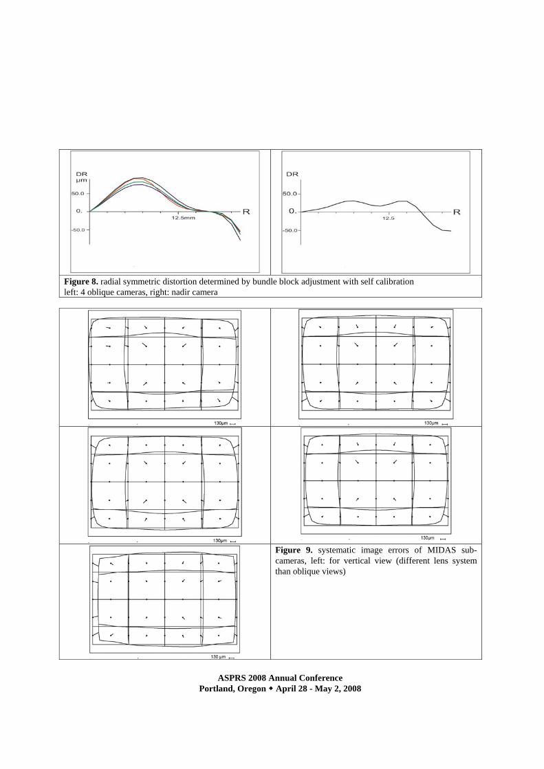
Figure 8. radial symmetric distortion determined by bundle block adjustment with self calibration left: 4 oblique cameras, right: nadir camera
Figure 9. systematic image errors of MIDAS sub-cameras, left: for vertical view (different lens system than oblique views)
ASPRS 2008 Annual Conference Portland, Oregon April 28 - May 2, 2008
By the adjustment of all images of the control-block (figure 5) the camera geometry has been determined. The dominating systematic image errors are the radial symmetric components with values up to 100µm. This is usual for the used optics. The radial symmetric distortions, as well as the overall systematic image errors, are similar for the oblique sub-cameras, using the same type of lens system. For the vertical sub-camera equipped with a different lens system it varies from the other. The systematic image errors, or in other words – the difference between the mathematical model of perspective geometry and the real image geometry, can be respected in the software system for handling the vertical and oblique images, or it can be used for resampling the images to strict perspective geometry.
sigma0 RMSX / RMSY
control points RMSZ
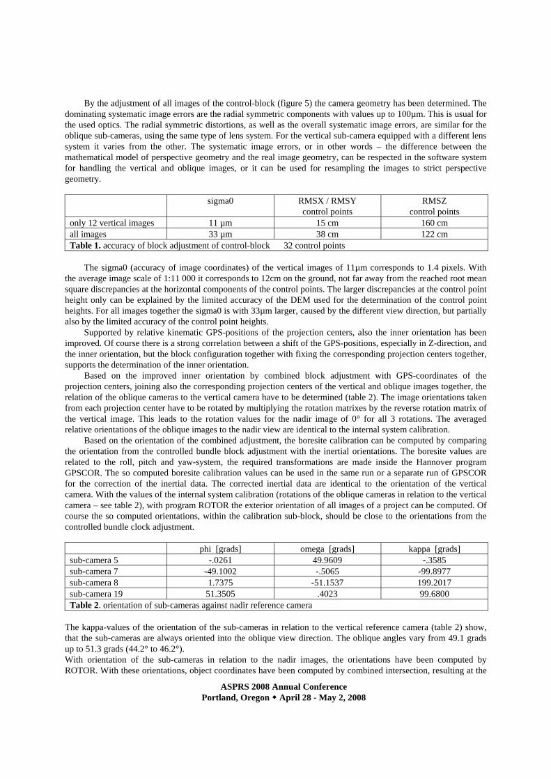
control points only 12 vertical images 11 µm 15 cm 160 cm all images 33 µm 38 cm 122 cm Table 1. accuracy of block adjustment of control-block 32 control points
The sigma0 (accuracy of image coordinates) of the vertical images of 11µm corresponds to 1.4 pixels. With
the average image scale of 1:11 000 it corresponds to 12cm on the ground, not far away from the reached root mean square discrepancies at the horizontal components of the control points. The larger discrepancies at the control point height only can be explained by the limited accuracy of the DEM used for the determination of the control point heights. For all images together the sigma0 is with 33µm larger, caused by the different view direction, but partially also by the limited accuracy of the control point heights.
Supported by relative kinematic GPS-positions of the projection centers, also the inner orientation has been improved. Of course there is a strong correlation between a shift of the GPS-positions, especially in Z-direction, and the inner orientation, but the block configuration together with fixing the corresponding projection centers together, supports the determination of the inner orientation.
Based on the improved inner orientation by combined block adjustment with GPS-coordinates of the projection centers, joining also the corresponding projection centers of the vertical and oblique images together, the relation of the oblique cameras to the vertical camera have to be determined (table 2). The image orientations taken from each projection center have to be rotated by multiplying the rotation matrixes by the reverse rotation matrix of the vertical image. This leads to the rotation values for the nadir image of 0° for all 3 rotations. The averaged relative orientations of the oblique images to the nadir view are identical to the internal system calibration.
Based on the orientation of the combined adjustment, the boresite calibration can be computed by comparing the orientation from the controlled bundle block adjustment with the inertial orientations. The boresite values are related to the roll, pitch and yaw-system, the required transformations are made inside the Hannover program GPSCOR. The so computed boresite calibration values can be used in the same run or a separate run of GPSCOR for the correction of the inertial data. The corrected inertial data are identical to the orientation of the vertical camera. With the values of the internal system calibration (rotations of the oblique cameras in relation to the vertical camera – see table 2), with program ROTOR the exterior orientation of all images of a project can be computed. Of course the so computed orientations, within the calibration sub-block, should be close to the orientations from the controlled bundle clock adjustment.
phi [grads] omega [grads] kappa [grads] sub-camera 5 -.0261 49.9609 -.3585 sub-camera 7 -49.1002 -.5065 -99.8977 sub-camera 8 1.7375 -51.1537 199.2017 sub-camera 19 51.3505 .4023 99.6800 Table 2. orientation of sub-cameras against nadir reference camera
The kappa-values of the orientation of the sub-cameras in relation to the vertical reference camera (table 2) show, that the sub-cameras are always oriented into the oblique view direction. The oblique angles vary from 49.1 grads up to 51.3 grads (44.2° to 46.2°). With orientation of the sub-cameras in relation to the nadir images, the orientations have been computed by ROTOR. With these orientations, object coordinates have been computed by combined intersection, resulting at the
ASPRS 2008 Annual Conference Portland, Oregon April 28 - May 2, 2008
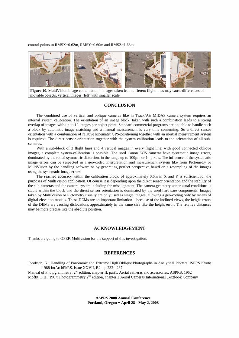
control points to RMSX=0.62m, RMSY=0.60m and RMSZ=1.63m.
Figure 10. MultiVision image combination – images taken from different flight lines may cause differences of movable objects, vertical images (left) with smaller scale
CONCLUSION
The combined use of vertical and oblique cameras like in Track’Air MIDAS camera system requires an
internal system calibration. The orientation of an image block, taken with such a combination leads to a strong overlap of images with up to 12 images per object point. Standard commercial programs are not able to handle such a block by automatic image matching and a manual measurement is very time consuming. So a direct sensor orientation with a combination of relative kinematic GPS-positioning together with an inertial measurement system is required. The direct sensor orientation together with the system calibration leads to the orientation of all sub-cameras.
With a sub-block of 3 flight lines and 4 vertical images in every flight line, with good connected oblique images, a complete system-calibration is possible. The used Canon EOS cameras have systematic image errors, dominated by the radial symmetric distortion, in the range up to 100µm or 14 pixels. The influence of the systematic image errors can be respected in a geo-coded interpretation and measurement system like from Pictometry or MultiVision by the handling software or by generating perfect perspective based on a resampling of the images using the systematic image errors.
The reached accuracy within the calibration block, of approximately 0.6m in X and Y is sufficient for the purposes of MultiVision application. Of course it is depending upon the direct sensor orientation and the stability of the sub-cameras and the camera system including the misalignment. The camera geometry under usual conditions is stable within the block and the direct sensor orientation is dominated by the used hardware components. Images taken by MultiVision or Pictometry usually are only used as single images, allowing a geo-coding only by means of digital elevation models. These DEMs are an important limitation – because of the inclined views, the height errors of the DEMs are causing dislocations approximately in the same size like the height error. The relative distances may be more precise like the absolute position.
ACKNOWLEDGEMENT
Thanks are going to OFEK Multivision for the support of this investigation.
REFERENCES
Jacobsen, K.: Handling of Panoramic and Extreme High Oblique Photographs in Analytical Plotters, ISPRS Kyoto 1988 IntArchPhRS. issue XXVII, B2, pp 232 - 237
Manual of Photogrammetry, 2nd edition, chapter II, part1, Aerial cameras and accessories, ASPRS, 1952 Moffit, F.H., 1967: Photogrammetry 2nd edition, chapter 2 Aerial Cameras International Textbook Company