Embed Size (px)
Citation preview

Calibration of a Mott electron polarimeter: Comparison of different methodsS. Mayer, T. Fischer, W. Blaschke, and J. Kessler Citation: Review of Scientific Instruments 64, 952 (1993); doi: 10.1063/1.1144148 View online: http://dx.doi.org/10.1063/1.1144148 View Table of Contents: http://scitation.aip.org/content/aip/journal/rsi/64/4?ver=pdfcov Published by the AIP Publishing Articles you may be interested in A cylindrically symmetric “micro-Mott” electron polarimeter Rev. Sci. Instrum. 87, 053302 (2016); 10.1063/1.4946995 Experimental comparison of a helium electron polarimeter with a calibrated high‐precision Mott detector Rev. Sci. Instrum. 66, 4885 (1995); 10.1063/1.1146170 Absolute calibration of a Mott polarimeter using surface Penning ionization Rev. Sci. Instrum. 63, 3519 (1992); 10.1063/1.1143759 Absolute calibration of a retarding‐potential Mott polarimeter Rev. Sci. Instrum. 62, 667 (1991); 10.1063/1.1142065 New method for accurate calibration of an electron‐spin polarimeter Rev. Sci. Instrum. 59, 49 (1988); 10.1063/1.1139964
Reuse of AIP Publishing content is subject to the terms at: https://publishing.aip.org/authors/rights-and-permissions. Download to IP: 129.57.87.13 On: Thu, 04
Aug 2016 12:59:06
Calibration of a Mott electron polarimeter: Comparison of different methods
S. Mayer, T. Fischer, W. Blaschke, and J. Kessler Physikalisches Institut der Universitiit Miinster, W-4400 Miinster, Germany
(Received 16 November 1992; accepted for publication 7 December 1992)
The accuracy of the calibration of a Mott polarimeter with a recently suggested method that uses an auxiliary target is compared with the accuracy obtained with the classical double-scattering experiment in its improved form. It turns out that the former method is affected by depolarization of the polarized incident beam in the auxiliary target. This systematic error source can, however, be eliminated by performing an additional asymmetry measurement.
I. INTRODUCTION
The interest in the accuracy of electron polarimetry has revived in the past few years. The issue came up be- cause major advances in polarized-electron sources had the consequence that the accuracy of many experiments with polarized electrons is no longer limited by statistics but rather by the uncertainty in the measurement of electron polarization.
The most common method for electron-polarization analysis is the measurement of the left-right scattering asymmetry A of an electron beam with polarization normal to the scattering plane. (For a recent review on this “Mott electron polarimetry,” see Ref. 1.) When L and R are the intensities scattered through the same angle 0 to the left and right, respectively, one has
A= (L-R)/( L+R). (1)
From this asymmetry one obtains the electron polarization
P= A/S,, (2)
if the analyzing power S,, (effective Sherman function) of the target is known.
By “calibration” of a Mott detector we mean in the following the determination of its effective analyzing power S,, which differs from the value that is usually calculated for free atoms. Its exact value is affected by multiple scat- tering and depends in a complicated way on the design parameters of the polarimeter. Careful experimental anal- yses ‘J of recent years have shown that the calibration of a Mott analyzer with an accuracy of 1% or below is a diffi- cult problem which has frequently been underestimated in the past.
A standard method of calibration is based on the dou- ble scattering of an initially unpolarized electron beam. If the parameters of the first and second scattering process (e.g., thickness of the target, electron energy, angles) are the same, S,, follows from the measured asymmetry A according to
A=$. (3)
In a recent paper3 we have described how this method has been improved to yield an accuracy better than 1%.
There are other calibration methods which are antici- pated to yield comparable accuracy. One can observe the
scattering asymmetry ,4 of a polarized electron beam whose polarization P is measured simultaneously by using the circularly polarized impact radiation which the polar- ized electrons produce when they excite helium atoms.4’5 In another method suggested by Hopster and Abraham6 one also employs a polarized beam, performing additional measurements with an auxiliary target in order to elimi- nate the electron polarization from the equations used to evaluate S,, . This will be substantiated in the following chapter.
~ The calibration is relatively easy if one assumes that one has an electron source of well-known polarization P, because then S,, is simply obtained by a measurement of the asymmetry A and evaluation of Eq. (2). Needless to say, in this case the value of P cannot be determined with the polarimeter to be calibrated but has to be derived from physical principles or independent measurements.’
In one of our projects we apply various methods of polarimeter calibration trying to compare their reliability and practical applicability. If one aims at accuracies better than 1% for the calibration one has to pay great attention to the systematic errors of the measurement. In order to verify the accuracy claimed one can compare various in- dependent calibration methods, checking whether they yield-within the error limits-the same result for one and the same Mott detector. Only if this is the case can one be sure to have successfully coped with the systematic errors.
In this paper we report on the calibration of a Mott analyzer using the idea suggested by Hopster and Abra- ham6 which will be called “auxiliary-target method” in the following. Comparison of this method with the calibration by double scattering shows that its accuracy is limited by a systematic depolarization effect resulting from multiple scattering in the auxiliary target.
II. CALIBRATION OF A MOTT DETECTOR USING THE AUXILIARY-TARGET METHOD
In order to determine the analyzing power S,, of the Mott detector one can perform the following measure- ments:
(i) The primary beam of polarization PO hits the target of the Mott detector directly [cf. Fig. l(i)]. One finds the left-right asymmetry
952 Rev. Sci. Instrum. 64 (4), April 1993 QQ34-6746/93/Q4Q952-Q66Q6.QQ @ 1993 American Institute of Physics 952 Reuse of AIP Publishing content is subject to the terms at: https://publishing.aip.org/authors/rights-and-permissions. Download to IP: 129.57.87.13 On: Thu, 04
Aug 2016 12:59:06
i)
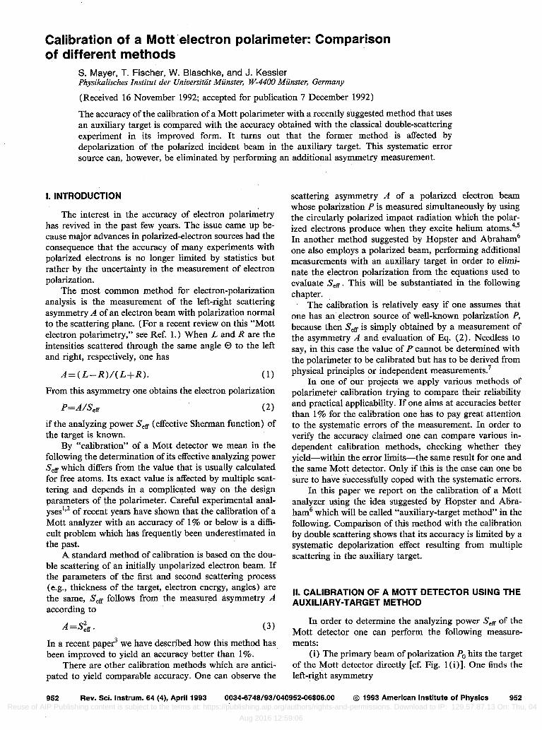
FIG. 1. Asymmetry measurements for determination of the analyzing power .S,, of a Mott detector.
L-R Ao=-- L+R -'&&*
(ii) The primary beam is scattered from the auxiliary target [cf. Fig. 1 (ii)]. The incident polarization PO is nor- mal to the scattering plane in all the cases considered. Reflection symmetry requires that the polarization of the scattered beam P, = (S,+P,)/( 1 + POST) is normal to the scattering plane as well (cf. Ref. 8, Chap. 3). ST is the analyzing power of the auxiliary target. When the scattered beam hits the target of the Mott detector one finds the asymmetry
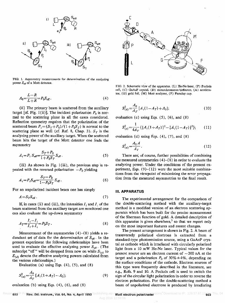
FIG. 2. Schematic view of the apparatus. IL) He-Ne laser, (P) Pockels cell, (C) GaAsP crystal, (D) monochromator/deflector, (A) accelera- tor, (G) gold foil, (M) Mott analyzer, (F) Faraday cup.
(4)
(iii) As shown in Fig. l(iii), the previous step is re- peated with the reversed polarization -PO yielding
sT-pO A, =PISeff=- S l-P&, effa (6)
For an unpolarized incident beam one has simply
A=S$&. (7)
If, in cases (ii) and (iii), the intensities I, and I, of the beam scattered from the auxiliary target are monitored one can also evaluate the up-down asymmetry
Measurement of the asymmetries (4)-( 8) yields a re- dundant set of data for the determination of S,, . In the present experiment the following relationships have been used to evaluate the effective analyzing power S,, . (The subscript “eff” will be dropped from now on while Scaj to Scd) denote the effective analyzing powers calculated from the various relationships.)
Evaluation (a) using Eqs. (4), (5), and (8)
A0 S?.)=~ [Attl+A~)-&I;
evaluation (b) using Eqs. (4), (6), and (8)
953 Rev. Sci. Instrum., Vol. 64, No. 4, April 1993
s:b)=~ [A,(l-ATT)+&]; T
evaluation (c) using Eqs. (5), (6), and (8)
sie~=~{[A,(l+AT)]2-[dl(1--dT)]z~; (11) evaluation (d) using E&s. (4), (7), and (8)
(12)
There are, of course, further possibilities of combining the measured asymmetries (4)-( 8) in order to evaluate the analyzing power. Under the conditions of the present ex- periment, Fqs. (9)-( 12) were the most suitable combina- tions from the viewpoint of minimizing the error propaga- tion from the measured asymmetries to the final result.
Ill. APPARATUS
The experimental arrangement for the comparison of the double-scattering method with the auxiliary-target method is a modified version of an electron scattering ap- paratus which has been built for the precise measurement of the Sherman function of gold. A detailed description of this apparatus is given elsewhere,3 so that we report only on the most important features and recent changes.
The present arrangement is shown in Fig. 2. A beam of transversely polarized electrons is extracted from a standard-type photoemission source, using a GaAsP crys- tal as cathode which is irradiated with circularly polarized light from a 10 mW He-Ne laser. Typical values for the present source are an electron current of -200 nA at the target and a polarization PO of 30% &4%, depending on the surface conditions of the cathode. Electron sources of this type were frequently described in the literature, see e.g., Refs. 9 and 10. A Pockels cell is used to switch the sign of the circular light polarization in order to reverse the electron polarization. For the double-scattering method a beam of unpolarized electrons is produced by irradiating
Mott electron polarimeter 953 Reuse of AIP Publishing content is subject to the terms at: https://publishing.aip.org/authors/rights-and-permissions. Download to IP: 129.57.87.13 On: Thu, 04
Aug 2016 12:59:06
the cathode with linearly polarized light. This is achieved by adjusting the voltage of the Pockels cell to the appro- priate value.
The beam emerging from the source passes through some transport optics and is then injected into the scatter- ing chamber via a 120 keV accelerator tube. For ease of operation the source is on ground potential, whereas the scattering chamber and the electron detection circuits are kept at + 120 keV. A gold foil serves as the auxiliary tar- get. For the double scattering according to Eq. (3) this gold foil must be a duplicate of the analyzer foil and the scattering angle must be the same as in the Mott analyzer. The polarization analyzer to be calibrated is a Mott detec- tor, containing a gold foil of (2 10 f. 3) pug/cm2 thickness as the target and monitor counters for the elimination of spu- rious asymmetries. The correction for instrumental asym- metries with the help of the monitor counters is carried out following the strategy described in Ref. 11. The scattering angle at the auxiliary target can be varied in the full range between 12.5” on the left side and 125” on the right side by rotating the Mott analyzer with the help of a stepper mo- tor. A Faraday cup serves as a monitor for the primary beam current.
The apparatus is controlled by a VME-bus computer which also accumulates and processes the experimental data. The computer is connected to the high-voltage part of the apparatus by fiber optic cables.
IV. CALIBRATION PROCEDURE AND RESULTS
For a reliable comparison of different calibration meth- ods one has to apply them to one and the same analyzer. Furthermore, care must be taken that.‘the experimental conditions remain the same during all necessary measure- ments. Excessive time delay, caused, e.g., by the change of targets or even worse by breaking the vacuum, should be avoided between the measurements because otherwise the results may be affected by drift effects.
The experimental comparison between the double- scattering and the auxiliary-target method, on which we report in this paper, was performed by switching as quickly as possible between the asymmetry measurements required for the two methods until the desired statistical accuracy was reached. The polarizer for the double-scattering method served also as the auxiliary target for calibration according to Eqs. (9)-( 12), and the scattering angle at this target remained fixed at 120” during the measurements of the asymmetries A, AT, At, and A,. Switching between the different asymmetry measurements was achieved by simply changing the voltage of the Pockels cell every two seconds so that spin-up electrons, spin-down electrons and-for the measurement of the asymmetry A-unpolarized electrons were alternately extracted from the source.
The production of unpolarized electrons with the source was more difficult than anticipated, because bire- fringence of the vacuum window, through which the laser beam entered the source, affected the light polarization. This. led to a clearly recognizible offset in electron polar- ization, even when the circular polarization of the laser
954 Rev. Sci. Instrum., Vol. 64, No. 4, April 1993
light was adjusted to zero outside the vacuum. The correct setting was found by monitoring the electron polarization with the Mott detector while adjusting the Pockels cell.
Another problem was connected with the measure- ment of the asymmetry Ac [see Fig. 1 (i)]. For this mea- surement the intensity of the primary beam had to be re- duced because otherwise the counters in the Mott detector would have been saturated. It turned out that the beam was intolerably depolarized down to 95% of its initial po- larization when the intensity was reduced by defocusing in front of an aperture. We therefore chose a different way of reducing the intensity, taking advantage of the fact that, for a scattering angle of 45”, the polarization of the scat- tered beam (S,+P,)/( 1 +P&,) is practically identical with the polarization PO of the primary beam, since the Sherman function ST of the gold target is practically zero at 45” (see Ref. 3). The asymmetry -4, was therefore de- termined with the reduced intensity of the beam scattered through 45” at the auxiliary target, so that the count rates in the Mott detector did not exceed 3 kHz. The disappear- ance of the Sherman function at this angle‘was veritied by scattering an unpolarized beam emerging from a thermal emission source and measuring the polarization of the elec- trons scattered through 45” with the Mott detector. No scattering asymmetry was observed within the statistical uncertainty of 10B3. In order to eliminate errors intro- duced by a shift in the scattering angle the scattering was alternately performed in the left and the right 45” position of the Mott analyzer.
The whole calibration procedure was divided into 76 runs, each lasting - 1 h. Every run started with a measure- ment of A0 before the Mott analyzer was turned into the 120” position for the measurement of the other asymme- tries. The intensities I, and I, were obtained by summing up the counts of the two monitor counters in the Mott detector while measuring the asymmetries A, and 21,. Be- fore calculating the asymmetry AT according to Eq. (8), the intensities were normalized to the primary beam cur- rent which was monitored with the help of the Faraday cup. This correction was necessary because of instrumental switching asymmetries, which sometimes reached values up to a few percent. Such asymmetries may, e.g., have been caused by a shift of the laser beam due to improper adjust- ment of the Pockels cell or birefringence of the vacuum window as discussed in Ref. 12. At the end of each run the A, measurement was repeated which always showed that there was no significant drift in polarization during a run. The mean value of the two A, values obtained at the be- ginning and at the end of such a run was therefore re- garded as the relevant A, value for the whole run.
For each run the analyzing power of the Mott detector was evaluated from the five Eqs. (3) and (9)-(12). In order to check the reproducibility of the measurements the standard deviation of the results from the 76 runs was calculated separately for each of the five evaluations. It turned out that the standard deviation never exceeded the statistical uncertainty of the mean value. Nevertheless, the various methods of evaluating the analyzing power of the Mott detector turned out to not be equivalent, as can be
Mott electron polarlmeter 954 Reuse of AIP Publishing content is subject to the terms at: https://publishing.aip.org/authors/rights-and-permissions. Download to IP: 129.57.87.13 On: Thu, 04
Aug 2016 12:59:06
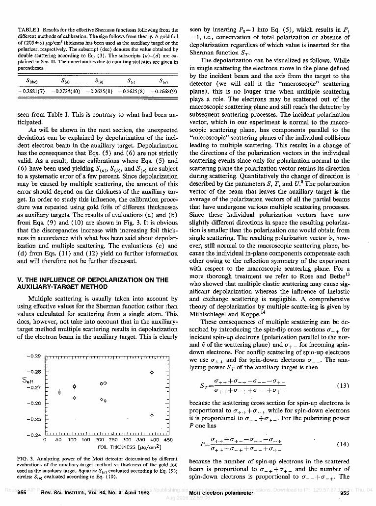
TABLE I. Results for the effective Sherman functions following from the different methods of calibration. The sign follows from theory. A gold foil of (205 * 3) ,ng/cm* thickness has been used as the auxiliary target or the polarizer, respectively. The subscript (dsc) denotes the value obtained by double scattering according to Eq. (3). The subscripts (a)-(d) are ex- plained in Sec. II. The uncertainties due to counting statistics are given in parentheses.
&dsc) s (4 ‘%I S(c) %)
-0.2681(7) -0.2724( 10) -0.2625(8) -0.2625(8) -0.2668(9)
seen from Table I. This is contrary to what had been an- ticipated.
As will be shown in the next section, the unexpected deviations can be explained by depolarization of the inci- dent electron beam in the auxiliary target. Depolarization has the consequence that Eqs. (5) and (6) are not strictly valid. As a result, those calibrations where Eqs. (5) and (6) have been used yielding S,,,, SCb), and S,,, are subject to a systematic error of a few percent. Since depolarization may be caused by multiple scattering, the amount of this error should depend on the thickness of the auxiliary tar- get. In order to study this influence, the calibration proce- dure was repeated using gold foils of different thicknesses as auxiliary targets. The results of evaluations (a) and (b) from Eqs. (9) and (10) are shown in Fig. 3. It is obvious that the discrepancies increase with increasing foil thick- ness in accordance with what has been said about depolar- ization and multiple scattering. The evaluations (c) and (d) from Eqs. ( 11) and ( 12) yield no further information and will therefore not be further discussed.
V. THE INFLUENCE OF DEPOLARIZATION ON THE AUXILIARY-TARGET METHOD
Multiple scattering is usually taken into account by using effective values for the Sherman function rather than values calculated for scattering from a single atom. This does, however, not take into account that in the auxiliary- target method multiple scattering results in depolarization of the electron beam in the auxiliary target. This is clearly
-0.29 ,,,,,,~,,,,m,,,,,,,,,,,,,~,,,,,,,,~,,,,~,,
-0.26 - -5 - s aff
-0.27 00
-0.26 00
-0.24 t~lIIIIIIIrI""""""'-""""""""IIIII 0 50 100 150 200 250 300 350 400 450
FOIL THICKNESS @g/cm21
FIG. 3. Analyzing power of the Mott detector determined by different evaluations of the auxiliary-target method vs thickness of the gold foil used as the auxiliary target. Squares: S,,, evaluated according to Rq. (9); circles: S(b) evaluated according to Eq. (IO).
955 Rev. Sci. Instrum., Vol. 64, No. 4, April 1993
seen by inserting PO= 1 into Eq. (5), which results in P, = 1, i.e., conservation of total polarization or absence of depolarization regardless of which value is inserted for the Sherman function ST.
The depolarization can be visualized as follows. While in single scattering the electrons move in the plane defined by the incident beam and the axis from the target to the detector (we will call it the “macroscopic” scattering plane), this is no longer true when multiple scattering plays a role. The electrons may be scattered out of the macroscopic scattering plane and still reach the detector by subsequent scattering processes. The incident polarization vector, which in our experiment is normal to the macro- scopic scattering plane, has components parallel to the “microscopic” scattering planes of the individual collisions leading to multiple scattering. This results in a change of the directions of the polarization vectors in the individual scattering events since only for polarization normal to the scattering plane the polarization vector retains its direction during scattering. Quantitatively the change of direction is described by the parameters S, T, and IY.~ The polarization vector of the beam that leaves the auxiliary target is the average of the polarization vectors of all the partial beams that have undergone various multiple scattering processes. Since these individual polarization vectors have now slightly different directions in space the resulting polariza- tion is smaller than the polarization one would obtain from single scattering. The resulting polarization vector is, how- ever, still normal to the macroscopic scattering plane, be- cause the individual in-plane components compensate each other owing to the reflection symmetry of the experiment with respect to the macroscopic scattering plane. For a more thorough treatment we refer to Rose and Bethel3 who showed that multiple elastic scattering may cause sig- nificant depolarization whereas the influence of inelastic and exchange scattering is negligible. A comprehensive theory of depolarization by multiple scattering is given by Miihlschlegel and Koppe. l4
These consequences of multiple scattering can be de- scribed by introducing the spin-flip cross sections (T- + for incident spin-up electrons (polarization parallel to the nor- mal n^ of the scattering plane) and (T+ _ for incoming spin- down electrons. For nonllip scattering of spin-up electrons we use CT+ + and for spin-down electrons o- _. The ana- lyzing power ST of the auxiliary target is then
s ~i.q.++~--+--L--~+~ T
a+++a-++a--+a+- (13)
because the scattering cross section for spin-up electrons is proportional to (T++ +a-+ while for spin-down electrons it is proportional to o- _ + o+ _. For the polarizing power P one has
(14)
because the number of spin-up electrons in the scattered beam is proportional to (T+ + +a+ _ and the number of spin-down electrons is proportional to o-- +a-+. The
Mott electron polarimeter 955 Reuse of AIP Publishing content is subject to the terms at: https://publishing.aip.org/authors/rights-and-permissions. Download to IP: 129.57.87.13 On: Thu, 04
Aug 2016 12:59:06
0
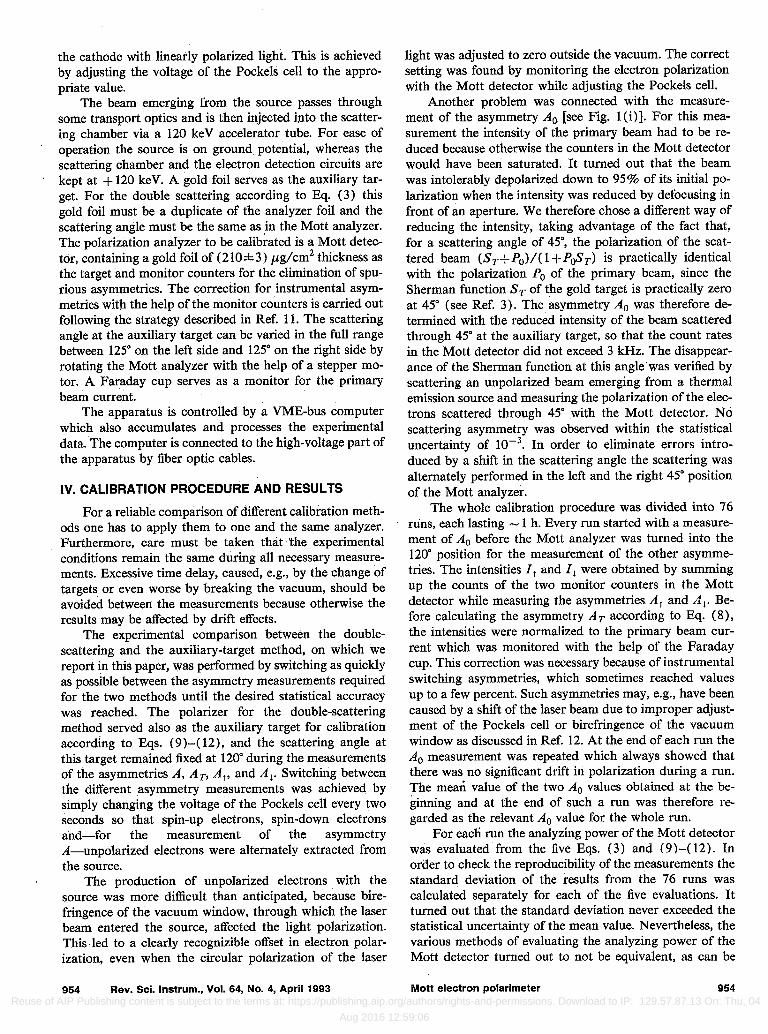
FIG. 4. Symmetry operations showing the equality of the spin-flip cross sections CT+ _ and o- + for specular scattering from the auxiliary target. (a) is transformed into (b) by time reversal, (b) into (c) by 180’ rotation around the dashed line.
equality of P and ST which-according to Eqs. (3), (5), and (6)-is required for the calibration methods studied, is only fulfilled if the two spin-flip cross sections are equal. In the case of specular elastic scattering Q+ _ can be trans- formed into (T-+ by time reversal and rotation by 180” around the surface normal of the target foil, as shown in Fig. 4. Since the scattering.~cross sections are invariant un- der these symmetry operations, CT+ _ must equal CT- + and the equality of ST and P is fulfilled. In our experiment the geometry was not specular since the incoming beam was perpendicular to the foil. Nevertheless, our present exper- imental data are, within the error limits, in agreement with the assumption ST= P also in that case. This will be shown at the end of the next section. In the following we will no longer distinguish between P and ST.
The depolarization effect becomes obvious when one calculates the polarization of the scattered beam in the case of non-zero initial polarization P,,. Taking into account that the number of spin-up electrons in the incoming beam is proportional to ( 1 +P,)/2 whereas the number of spin- down projectiles is proportional to ( 1 -P,)/2, one obtains from Eq. ( 14) for primary polarization parallel to A
1+po l-P0 1+po l-P0 ----a+++ 2 2 -------IT+---C- 2 +-7j-a--
Pr= l+Po l-P0 l+Po l-P, * -a+++ 2 2 -a+-+-y- “-+f 2 -a--
(15) Straightforward calculation using Eq. ( 13) yields
(16)
where
a=l--2 a+-+a-+
a+++a-++a--+a+-.’ (17)
For primary polarization reversed one obtains
(181
These expressions differ from Eqs. (5) and (6) by the depolarization factor a which is mainly determined by the
956 Rev. Sci. Instrum., Vol. 64, No. 4, April 1993
1.05
a
1.00
0.95
0.90 0 50 100 150 200 250 300 350 400 450
FOIL THICKNESS [pg/m2]
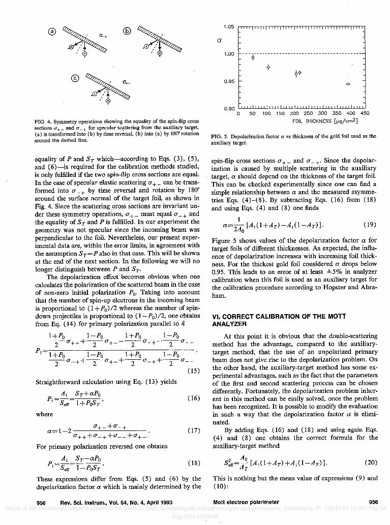
FIG. 5. Depolarization factor CL vs thickness of the gold foil used as the auxiliary target.
spin-flip cross sections (T+ _ and (T- +. Since the depolar- ization is caused by multiple scattering in the auxiliary target, a should depend on the thickness of the target foil. This can be checked experimentally since one can find a simple relationship between a and the measured asymme- tries Eqs. (4)-( 8). By subtracting Eqs. ( 16) from ( 18) and using Eqs. (4) and (8) one finds
a=& [At(l+A~)--AL(l--AT)]. Figure 5 shows values of the depolarization factor a for target foils of different thicknesses. As expected, the influ- ence of depolarization increases with increasing foil thick- ness. For the thickest gold foil considered a drops below 0.95. This leads to an error of at least *5% in analyzer calibration when this foil is used as an auxiliary target for the calibration procedure according to Hopster and Abra- ham.
VI. CORRECT CALIBRATION OF THE MOTT ANALYZER
At this point it is obvious that the double-scattering method has the advantage, compared to the auxiliary- target method, that the use of an unpolarized primary beam does not give rise to the depolarization problem. On the other hand, the auxiliary-target method has some ex- perimental advantages, such as the fact that the parameters of the first and second scattering process can be chosen differently. Fortunately, the depolarization problem inher- ent in this method can be easily solved, once the problem has been recognized, It is possible to modify the evaluation in such a way that the depolarization factor a is elimi- nated.
By adding Eqs. (16) and (18) and using again Eqs. (4) and (8) one obtains the correct formula for the auxiliary-target method
s;,yT=$T [~4,(1+A.)+A,(l--A,)]. (20)
This is nothing but the mean value of expressions (9) and (10):
Mott electron polarimeter 956 Reuse of AIP Publishing content is subject to the terms at: https://publishing.aip.org/authors/rights-and-permissions. Download to IP: 129.57.87.13 On: Thu, 04
Aug 2016 12:59:06
-0.29 ,,*~,,,,,,~,,~,,,,,,,‘,,,,‘,,,‘,’,,,,,~,,,~,-
-0.28 -
s aff -0.27 -
-eQ 0 00 0
-0.26 -
-0.25 -
-0.24 ““““““““““““i’l”“““““““’ 0 50 100 150 200 250 300 350 400 450
FOIL THICKNESS [pg/cm2]
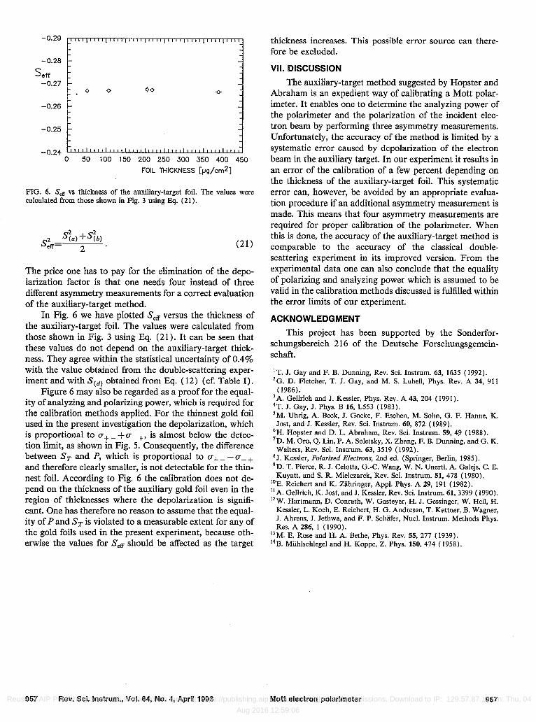
FIG. 6. S,, vs thickness of the auxiliary-target foil. The values were calculated from those shown in Fig. 3 using E$. (21).
s:,=s~~) ;‘%’ , (21)
The price one has to pay for the elimination of the depo- larization factor is that one needs four instead of three different asymmetry measurements for a correct evaluation of the auxiliary-target method.
In Fig. 6 we have plotted Se, versus the thickness of the auxiliary-target foil. The values were calculated from those shown in Fig. 3 using Eq. (21). It can be seen that these values do not depend on the auxiliary-target thick- ness. They agree within the statistical uncertainty of 0.4% with the value obtained from the double-scattering exper- iment and with ScdJ obtained from Eq. ( 12) (cf. Table I).
Figure 6 may also be regarded as a proof for the equal- ity of analyzing and polarizing power, which is required for the calibration methods applied. For the thinnest gold foil used in the present investigation the depolarization, which is proportional to o+ _ + cr-+, is almost below the detec- tion limit, as shown in Fig. 5. Consequently, the difference between ST and P, which is proportional to CT+ _ -(T- + and therefore clearly smaller, is not detectable for the thin- nest foil. According to Fig. 6 the calibration does not de- pend on the thickness of the auxiliary gold foil even in the region of thicknesses where the depolarization is signifi- cant. One has therefore no reason to assume that the equal- ity of P and ST is violated to a measurable extent for any of the gold foils used in the present experiment, because oth- erwise the values for Se, should be affected as the target
thickness increases. This possible error source can there- fore be excluded.
VII. DISCUSSION The auxiliary-target method suggested by Hopster and
Abraham is an expedient way of calibrating a Mott polar- imeter. It enables one to determine the analyzing power of the polarimeter and the polarization of the incident elec- tron beam by performing three asymmetry measurements. Unfortunately, the accuracy of the method is limited by a systematic error caused by depolarization of the electron beam in the auxiliary target. In our experiment it results in an error of the calibration of a few percent depending on the thickness of the auxiliary-target foil. This systematic error can, however, be avoided by an appropriate evalua- tion procedure if an additional asymmetry measurement is made. This means that four asymmetry measurements are required for proper calibration of the polarimeter. When this is done, the accuracy of the auxiliary-target method is comparable to the accuracy of the classical double- scattering experiment in its improved version. From the experimental data one can also conclude that the equality of polarizing and analyzing power which is assumed to be valid in the calibration methods discussed is fulfilled within the error limits of our experiment.
ACKNOWLEDGMENT This project has been supported by the Sonderfor-
schungsbereich 2 16 of the Deutsche Forschungsgemein- schaft.
‘T. J. Gay and F. B. Dunning, Rev. Sci. Instrum. 63, 1635 (1992). ‘G. D. Fletcher, T. J. Gay, and M. S. Lubell, Phys. Rev. A 34, 911
(1986). ‘A. Gellrich and J. Kessler, Phys. Rev. A 43, 204 (1991). 4T. J. Gay, J. Phys. B 16, L553 (1983). 5M. Uhrig, A. Beck, J. Goeke, F. Eschen, M. Sohn, G. F. Hanne, K. Jost, and J. Kessler, Rev. Sci. Instrum. 60, 872 (1989).
‘H. Hopster and D. L. Abraham, Rev. Sci. Instrum. 59, 49 (1988). 7D. M. Oro, Q. Lin, P. A. Soletsky, X. Zhang, F. B. Dunning, and G. K.
Walters, Rev. Sci. Instrum. 63, 35 19 (1992). *J. Kessler, Polarized Electrons, 2nd ed. (Springer, Berlin, 1985). ‘D. T. Pierce, R. J. Celotta, G.-C. Wang, W. N. Unertl, A. Galejs, C. E.
Kuyatt. and S. R. Mielczarek, Rev. Sci. Instrum. 51, 478 (1980). “E. Reichert and K. Zahringer, Appl. Phys. A 29, 191 (1982). ” A. Gelhich, K. Jost, and J. Kessler, Rev. Sci. Instrum. 61, 3399 ( 1990). ‘*W. Hartmann, D. Conrath, W. Gasteyer, H. J. Gessinger, W. He& H.
Kessler, L. Koch, E. Reichert, H. G. Andresen, T. Kettner, B. Wagner, J. Ahrens, J. Jethwa, and F. P. Schafer, Nucl. Instrum. Methods Phys. Res. A 286, 1 ( 1990).
i3 M. E. Rose and H. A. Bethe, Phys. Rev. 55, 277 (1939). i4B. Miihlschlegel and H. Koppe, Z. Phys. 150, 474 (1958).
957 Rev. Sci. Instrum., Vol. 64, No. 4, April 1993 Mott electron polarimeter 957 Reuse of AIP Publishing content is subject to the terms at: https://publishing.aip.org/authors/rights-and-permissions. Download to IP: 129.57.87.13 On: Thu, 04
Aug 2016 12:59:06