Embed Size (px)
Citation preview

Calibration and Settings EVC-E2 IPS350/400/450/500/600
IPS800/950 IPS1050/1200


Table of Contents
Calibration and Settings, general ....................................................................................2
Controls and Steering system....................................................................................... ....5
Alarm handling.................................................................................................................. .........7
Acknowledge message .........................................................................................................7
IPS calibration ............................................................................................................................8
Calibrating Volvo Penta IPS drive units....................................................................... . 9
Steering mode ........................................................................................................................ 11
Auto configuration, twin installation ............................................................................12
Auto configuration, triple installation ..........................................................................14
Auto configuration, quadruple installtion .................................................................. 16
Auto configuration, 4” display .........................................................................................18
Auto configuration, 7” display .........................................................................................19
Auto configuration, analog lever....................................................................................21
Language .................................................................................................................................. 22
Units .............................................................................................................................................23
Add e-Key ..................................................................................................................................24
Lever calibration, top mounted lever ...........................................................................25
Lever calibration, analog lever with stand-aloneHCU ........................................27
Fuel tank settings ................................................................................................................. 29
Multi-point calibration .........................................................................................................31
Water in oil sensor ................................................................................................................32
Slip calibration ........................................................................................................................33
Idling speed calibration ......................................................................................................35
Calibrating the Joystick function ...................................................................................36
Joystick docking force ........................................................................................................38
Calibration of Interceptor System.................................................................................39
Depth Alarm .............................................................................................................................45
Autopilot (4” display) ...........................................................................................................46
Fuel tank settings (Volvo Penta Glass Cockpit) ....................................................51
Autopilot (Volvo Penta Glass Cockpit) .......................................................................53

Calibration and SettingsGeneral• When the installation is complete, auto-configura-
tion and calibration of the controls must always becarried out. Keys must be added to the system.
• Auto-configuration means that the system detectsand defines all the components connected to it.
• Perform the calibrations according to the order inthis manual.
• Auto-configuration must always be carried out whenany changes are made to the EVC system, e.g. ifthe system is extended or modified.
• During control lever calibration, lever settings andidle rpm are defined for the EVC system. If a controllever is replaced, the new one must be calibrated.
• The engine cannot be started until keys are addedto the system.
NOTICE! Not all steps are shown for new installations.These exceptions are marked by asterisks (*) in theillustration sequences.
e-KeyThe key fob is held in front of the panel to unlock theboat's EVC system. There are ignition and Start/Stopbuttons for each driveline.The system has autostart, which means the buttonneed only be pressed once to start the engines.The system will attempt to start the engines for a max-imum of 10 seconds after which the starter motor circuitis broken to protect the starter motor from overheating.If possible, allow the starter motor to cool for at leastfive minutes before making a new start attempt.
IGNITION IGNITION
START/STOP START/STOP
P0016313
2 47705854 05-2014 © AB VOLVO PENTA

Displays
7" display
A. Controls instrument lighting.
B. Press to go back in the menu.
C. Confirm selection. Open sub menus and the Set-tings menu.
D. Turn to scroll through the menus.
4" display
B. Press to go back in the menu.
B. Button functions are shown on screen; theychange according to the menu selection.
C. Controls instrument lighting.
2.5" display
B. Press to go back in the menu. Press repeatedlyto return to the main menu; alternatively, holddown the button for a couple of seconds.
B. Go left or up in the menu.
B. Go right or down in the menu.
D. Confirm selection.
Multifunction panel
A. Button function depends on the softwareinstalled.
Calibration and Settings
47705854 05-2014 © AB VOLVO PENTA 3

Volvo Penta Glass Cockpit
The Home menu is divided into fields:
A. Warning and alarm symbols.
B. Active function symbols.
C. Shows current Autopilot settings.
D. Settings with further selections.
E. Optional screen functions.
F. Main menus in home screen.
GARMIN
SettingsEngage SOSSettingsEngage Waypoints Info MENU Mark SOS
MY VESSEL
Home
A B
D
C
E F
P 1990000
Calibration and Settings
4 47705854 05-2014 © AB VOLVO PENTA
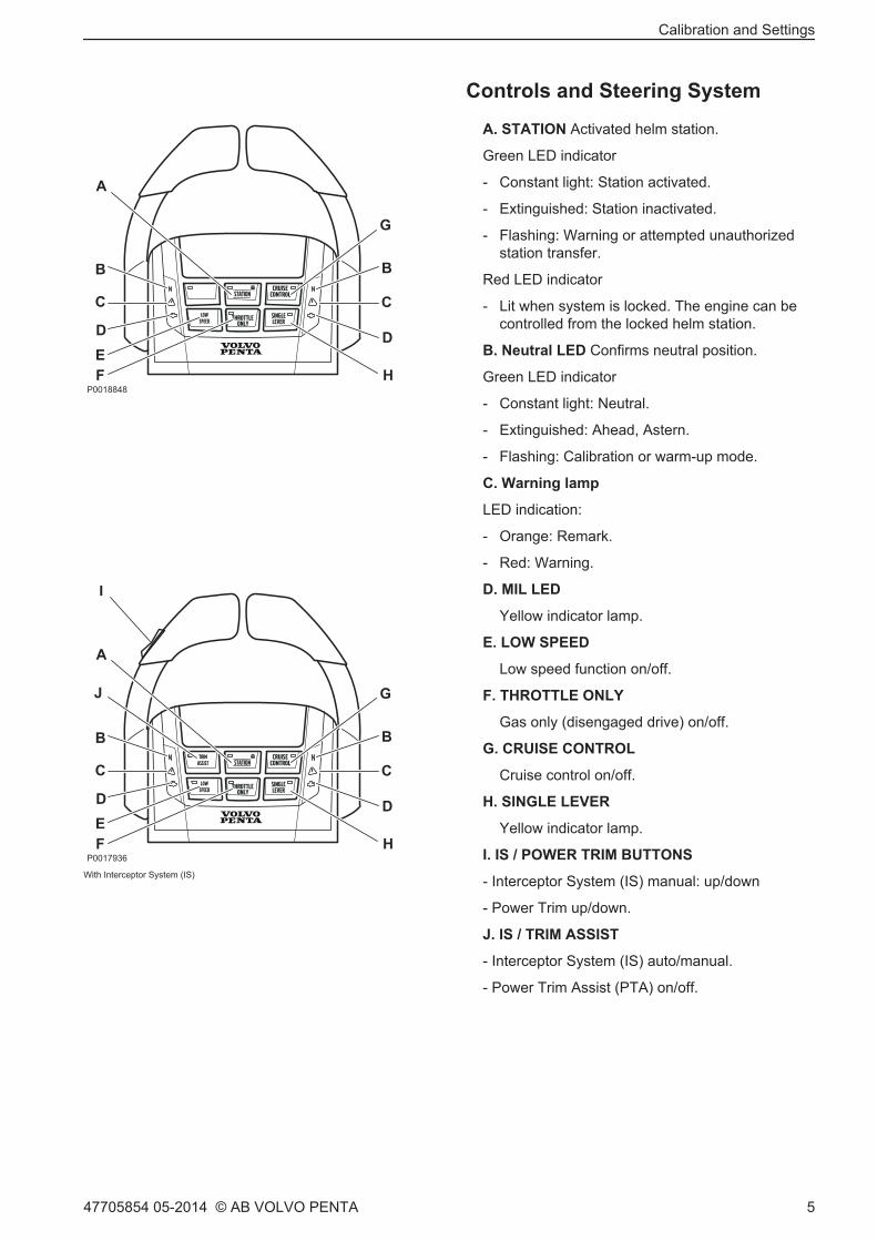
Controls and Steering System
A. STATION Activated helm station.
Green LED indicator
- Constant light: Station activated.
- Extinguished: Station inactivated.
- Flashing: Warning or attempted unauthorizedstation transfer.
Red LED indicator
- Lit when system is locked. The engine can becontrolled from the locked helm station.
B. Neutral LED Confirms neutral position.
Green LED indicator
- Constant light: Neutral.
- Extinguished: Ahead, Astern.
- Flashing: Calibration or warm-up mode.
C. Warning lamp
LED indication:
- Orange: Remark.
- Red: Warning.
D. MIL LED
Yellow indicator lamp.
E. LOW SPEED
Low speed function on/off.
F. THROTTLE ONLY
Gas only (disengaged drive) on/off.
G. CRUISE CONTROL
Cruise control on/off.
H. SINGLE LEVER
Yellow indicator lamp.
I. IS / POWER TRIM BUTTONS
- Interceptor System (IS) manual: up/down
- Power Trim up/down.
J. IS / TRIM ASSIST
- Interceptor System (IS) auto/manual.
- Power Trim Assist (PTA) on/off.
LOWSPEED
STATION
THROTTLEONLY
CRUISECONTROL
SINGLELEVER
C
DEF
C
D
BB
A
G
HP0018848
LOWSPEED
STATION
THROTTLEONLY
CRUISECONTROL
SINGLELEVER
C
DEF
C
D
BB
A
G
H
I
TRIMASSIST
J
P 1793600
With Interceptor System (IS)
Calibration and Settings
47705854 05-2014 © AB VOLVO PENTA 5

Joystick
A. DYNAMIC POSITIONING SYSTEM
Dynamic positioning system on/off.
B. JOYSTICK DRIVING
Joystick steering on/off.
C. HIGH MODE
Extra power on/off.
D. DOCKING
Docking function on/off.
Calibration and Settings
6 47705854 05-2014 © AB VOLVO PENTA

Alarm handling
Error message from the engine and EVCsystem.The engine, transmission and the EVC system aremonitored and checked by the diagnostics function.Should the diagnostic function discover a malfunctionit will protect the engine and ensure continued opera-tion by controlling the engine. The engine is controlledin different ways depending on the severity of the fault.
When a malfunction is detected, the helmsman iswarned by an audible alarm and a message is dis-played on the screen.The message shows the cause of the fault and its rem-edy. This information is also available in the Fault CodeRegister in the engine's Operator's Manual.
Acknowledge message
1 Push OK to ackowledge the alarm. The buzzerbecomes silent.
2 Read the message.
3 Push OK again and the message disappears.
The alarm has to be acknowledged before the enginecan be started.
Battery voltage incorrect.Check voltage level, alternator andbatteries
Acknowledge fault by pressing the OK buttonContact a Volvo Penta workshop if thefaults remains.
P 1248900
Calibration and Settings
47705854 05-2014 © AB VOLVO PENTA 7

IPS CalibrationThe VODIA diagnostic tool may be used to adjust EVCsystem parameters. This is done with the Parameterprogramming tool in the Service and maintenancemenu.
VODIA is a special tool from Volvo Penta, refer toVolvo Penta Partner Network to order.Further information about VODIA use is available in theVODIA Operator's Manual that can be downloadedfrom Volvo Penta Partner Network.
Once contact with the system has been established,contact is then made with the specific ECU (EngineControl Unit) in the menu to show which unit parame-ters can be adjusted.
Adjustable parameters
NOTICE! Certain parameters may require special per-mission for adjustment.
Neutral signalVODIA text: ”Neutral signal”.Activated for one PCU (MID 187).The parameter enables activation or deactivation ofthe control lever neutral position function.The function can be activated individually at helm sta-tion HCUs. If the function is required for all helm sta-tions it must be activated in the PCU via VODIA. Thisaffects all helm stations for the driveline concernedwith up to four HCUs possible per driveline.
Calibration and Settings
8 47705854 05-2014 © AB VOLVO PENTA

Calibrating Volvo Penta IPS drive unitsPerformed by the OEM and consists of two parts: Drive leg position, which calibrates the relative positionsbetween the drive and Drive Alignment, is carried out using a centering tool for the drives.
1. Control lever in neu-tral position.
2. Turn on the ignition. 3. Connect to VODIA. (Example shows quad)
4. Select function groupSteering.
5. Select calibration. 6. Select OEM. 7. Select installation type.
8. Preconditions. 9. Step 1: Start Drive legposition and follow theinstructions.
10. For example: Is themarked drive leg mov-ing?
11. Cut the current with themain switches. Wait 10 sec-onds.
12. Turn the main switchon.
13. Confirm with OK. 14. Step 2: Start Drivealignment and follow theinstructions.
15. Confirm the hull ID.
Calibration and Settings
47705854 05-2014 © AB VOLVO PENTA 9

16. Select driveline.Adjust the drive witharrow buttons and pressDone.
17. Repeat for additionalengines.
18. Are you sure that thedrive legs are alignedwith the center position-ing tool?
19. Caution! Remove thepositioning tool.
20. Report the resultwithin 28 days.
21. VODIA web, selectReport software.
Calibration and Settings
10 47705854 05-2014 © AB VOLVO PENTA

Steering modeSteering mode specifies the relative positions between the drives. Select between steering rates Minimum,Medium and Maximum. Additionally, IPS2 and IPS3 have two medium positions: low and high. Maximum steeringrate provides the smallest turning radius.NOTICE! Where necessary, determine steering mode settings according to the Sea Trial Wizard.
1. Move control to neu-tral.
2. Turn the ignition on. 3. Connect to VODIA. (Example shows quad)
4. Select function groupSteering.
5. Configuration. 6. Steering mode. 7. Select installation type.
8. Preconditions 9. Tap Play to start. 10. Select steeringmode.
11. Report the resultwithin 28 days.
12. VODIA web, selectReport software.
Calibration and Settings
47705854 05-2014 © AB VOLVO PENTA 11

Auto configuration, twin installation
In example below the 2.5" display is used. If 4" or 7" display, use keys / knobs to navigate and OK to confirm.* Indication not shown / skip the item during new installation.
1. Put the gear in neutral 2.* Turn the ignition on. 3. Press THROTTLEONLY
4.* Indicates that calibrationmode is activated.
5.* Calibration Mode 1.0 6. Press THROTTLEONLY
7.* Auto configurationbegun.
8. Wait.
Select Panel TypeStart/Stop Panel
9. Select the engine to be shown in each display.Confirm with OK.
10. If multifunctionpanel: select type ofpanel.
11. Confirm with OK.
12. Configure any tach-ometer.
13. Allocate tachometer.Scroll using the arrowbuttons.
14. Allocate port tach-ometer.
15. Confirm with OK.
Calibration and Settings
12 47705854 05-2014 © AB VOLVO PENTA

16. Port ready, allocatestarboard.
17. Confirm with OK. 18. Starboard con-firmed.
19. Repeat steps 9–18for further helm stations.
20. Restart the system to confirm the calibration.
Calibration and Settings
47705854 05-2014 © AB VOLVO PENTA 13
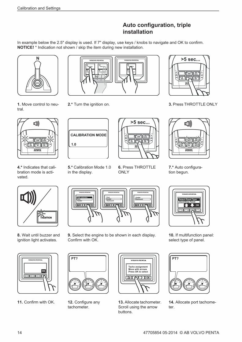
Auto configuration, tripleinstallation
In example below the 2.5" display is used. If 7" display, use keys / knobs to navigate and OK to confirm.NOTICE! * Indication not shown / skip the item during new installation.
IGNITION IGNITION
START/STOP START/STOP
IGNITION
START/STOP
1. Move control to neu-tral.
2.* Turn the ignition on. 3. Press THROTTLE ONLY
4.* Indicates that cali-bration mode is acti-vated.
5.* Calibration Mode 1.0in the display.
6. Press THROTTLEONLY
7.* Auto configura-tion begun.
Select Panel TypeStart/Stop Panel
8. Wait until buzzer andignition light activates.
9. Select the engine to be shown in each display.Confirm with OK.
10. If multifunction panel:select type of panel.
11. Confirm with OK. 12. Configure anytachometer.
13. Allocate tachometer.Scroll using the arrowbuttons.
14. Allocate port tachome-ter.
Calibration and Settings
14 47705854 05-2014 © AB VOLVO PENTA
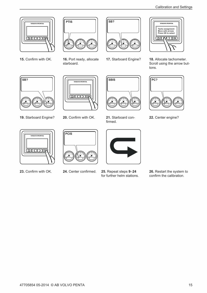
15. Confirm with OK. 16. Port ready, allocatestarboard.
17. Starboard Engine? 18. Allocate tachometer.Scroll using the arrow but-tons.
19. Starboard Engine? 20. Confirm with OK. 21. Starboard con-firmed.
22. Center engine?
23. Confirm with OK. 24. Center confirmed. 25. Repeat steps 9–24for further helm stations.
26. Restart the system toconfirm the calibration.
Calibration and Settings
47705854 05-2014 © AB VOLVO PENTA 15
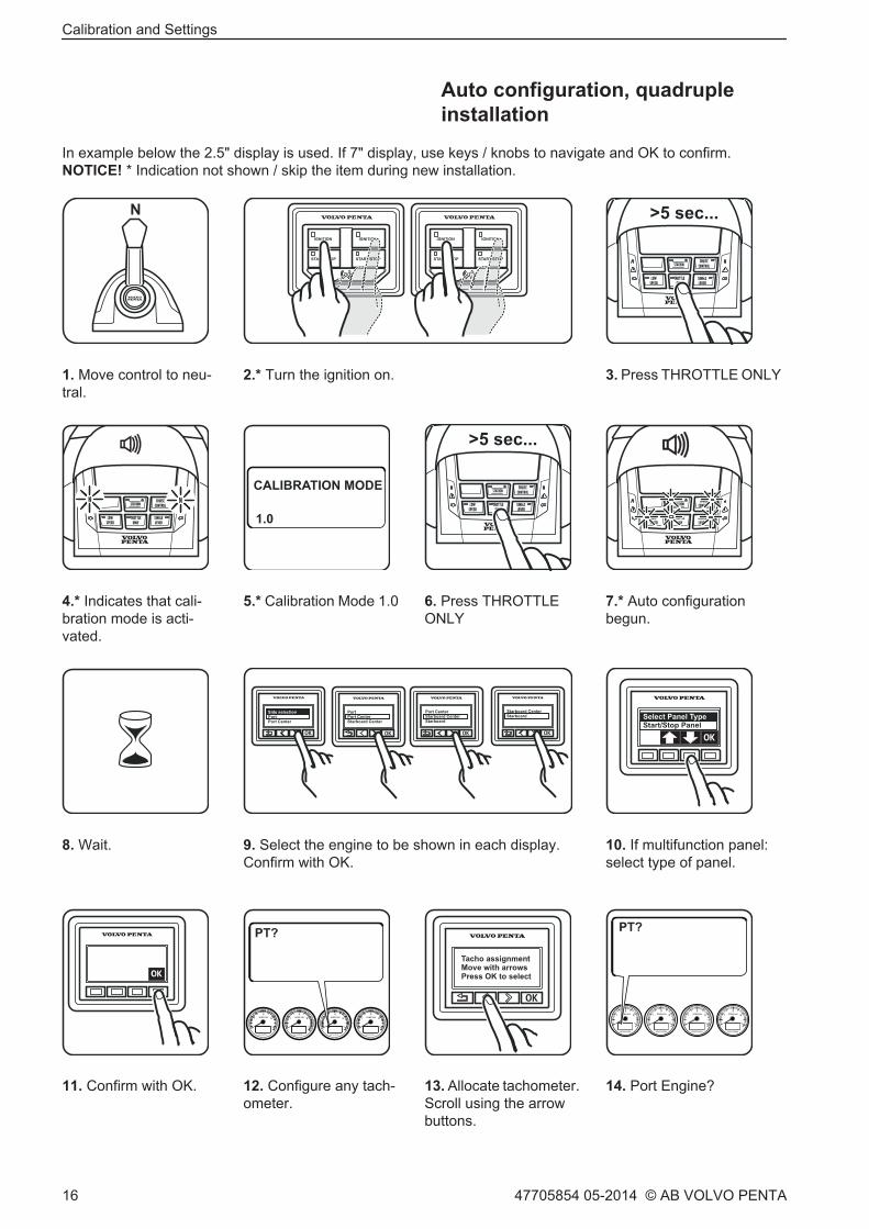
Auto configuration, quadrupleinstallation
In example below the 2.5" display is used. If 7" display, use keys / knobs to navigate and OK to confirm.NOTICE! * Indication not shown / skip the item during new installation.
IGNITION IGNITION
START/STOP START/STOP
IGNITION IGNITION
START/STOP START/STOP
1. Move control to neu-tral.
2.* Turn the ignition on. 3. Press THROTTLE ONLY
4.* Indicates that cali-bration mode is acti-vated.
5.* Calibration Mode 1.0 6. Press THROTTLEONLY
7.* Auto configurationbegun.
Select Panel TypeStart/Stop Panel
8. Wait. 9. Select the engine to be shown in each display.Confirm with OK.
10. If multifunction panel:select type of panel.
11. Confirm with OK. 12. Configure any tach-ometer.
13. Allocate tachometer.Scroll using the arrowbuttons.
14. Port Engine?
Calibration and Settings
16 47705854 05-2014 © AB VOLVO PENTA
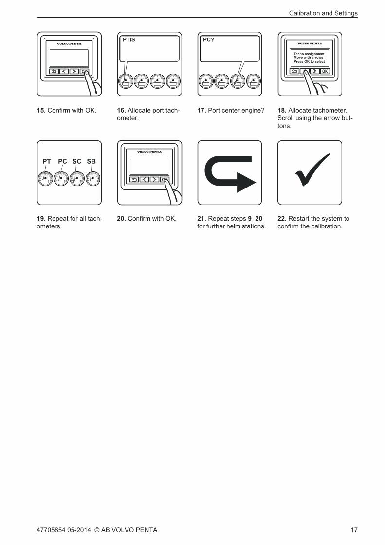
15. Confirm with OK. 16. Allocate port tach-ometer.
17. Port center engine? 18. Allocate tachometer.Scroll using the arrow but-tons.
19. Repeat for all tach-ometers.
20. Confirm with OK. 21. Repeat steps 9–20for further helm stations.
22. Restart the system toconfirm the calibration.
Calibration and Settings
47705854 05-2014 © AB VOLVO PENTA 17

Auto configuration, 4" display
NOTICE! 4” display can not be used in combination with 2,5” or 7” display at the same helm station.NOTICE! * Indication not shown / skip the item during new installation. (Example below show a twin installation)
1. Move control to neu-tral.
2.* Turn the ignition on. 3. Press THROTTLEONLY
4.* Indicates that calibra-tion mode is activated.
5.* Calibration Mode1.0
6. Press THROTTLEONLY
7.* Auto configurationbegun.
8. Wait.
Select Panel TypeStart/Stop Panel
9. If multifunction panel:select type of panel.Confirm with OK.
10. Select display type.Confirm with OK.
11. Configure any tach-ometer.
12. Allocate tachometer.Scroll using the arrow but-tons.
13. Allocate port tach-ometer.Confirm with OK.
14. Port ready, allocatestarboard.Confirm with OK.
15. Starboard con-firmed.
16. Repeat steps 9–15 forfurther helm stations.
17. Restart the system to confirm the calibration.
Calibration and Settings
18 47705854 05-2014 © AB VOLVO PENTA

Auto configuration, 7" display
NOTICE! If two 7” displays are used on one helm station they must be configured as TWIN/TWIN SECONDARYrespective port/starboard (on twin installations) as TRIPLE/TRIPLE SECONDARY (on triple installations) and asQUAD PORT/QUAD STARBOARD (on quad installations)
NOTICE! * Indication not shown / skip the item during new installation.
(Example below show a twin installation)
1. Move control to neu-tral.
2.* Turn the ignition on. 3. Press THROTTLEONLY
4.* Indicates that cal-ibration mode is acti-vated.
5.* Calibration Mode 1.0 6. Press THROTTLEONLY
7.* Auto configurationbegun.
8. Wait.
Select Panel TypeStart/Stop Panel
9. If multifunction panel:select type of panel.
10. Confirm with OK. 11. Configure any tach-ometer.
12. Allocate tachometer.Scroll using the arrow but-tons.
Calibration and Settings
47705854 05-2014 © AB VOLVO PENTA 19

13. Allocate port tach-ometer.Confirm with OK.
14. Port ready, allocatestarboard.Confirm with OK.
15. Starboard con-firmed.
16. Repeat steps 9–15 forfurther helm stations.
17. Restart the system to confirm the calibration.
Calibration and Settings
20 47705854 05-2014 © AB VOLVO PENTA

Auto configuration, analog lever
In example below the 2.5" display is used. If 7" display, use keys / knobs to navigate and OK to confirm.NOTICE! * Indication not shown / skip the item during new installation. (Example below show a twin installation)
OK
>5 sec...
1. Move control to neu-tral.
2.* Turn the ignition on. 3. Set active station. 4.* Calibration Mode 1.0
Select Panel TypeStart/Stop Panel
5. Push the Neutral but-ton.
6. Wait. 7. Select Port engine.Confirm with OK.
8. If multifunction panel:select type of panel.(1)
9. Confirm with OK. 10. Configure any tach-ometer.
11. Allocate tachometer.Scroll using the arrowbuttons.
12. Confirm with OK.
13. Allocate port tach-ometer. OK
14. Port ready, allocatestarboard. OK
15. Starboard con-firmed.
16. Repeat steps 7–15 forfurther helm stations.
17. Restart the system to confirm the calibration.
1. Start/Stop panel required at each station.
Calibration and Settings
47705854 05-2014 © AB VOLVO PENTA 21

Language
Select preferred language:English, Danish, Finnish, French, Dutch, Italian, Portuguese, Spanish, Swedish and German.
NOTICE! The setting need only be made at one helm station to be displayed on all screens at all helm stations.
1. Turn the ignition on. 2. Scroll the menu. 3. Settings 4. Confirm with OK.
5. Scroll to Languagemenu.
6. Confirm with OK. 7. Select preferredlanguage.
8. Confirm with OK.
9. Restart the systemto confirm the cali-bration.
Calibration and Settings
22 47705854 05-2014 © AB VOLVO PENTA

Units
NOTICE! The setting need only be made at one helm station to be displayed on all screens at all helm stations.
1. Turn the ignition on. 2. Scroll the menu. 3. Settings 4. Confirm with OK.
5. Scroll to the Unitsmenu.
6. Confirm with OK. 7. Select preferred units. 8. Confirm with OK.
9. Select preferred units. 10. Confirm with OK. 11. Scroll to set units ofdistance.
12. Scroll to Distance.
13. Confirm with OK. 14. Select unit and con-firm with OK.
15. Restart the systemto confirm the calibra-tion.
Calibration and Settings
47705854 05-2014 © AB VOLVO PENTA 23

Add e-Key
NOTICE! The ignition must be on and engine(s) stopped.
1. Move control to neu-tral.
2. Turn the ignition on. 3. Scroll the menu. 4. Settings.
5. Confirm with OK. 6. Scroll to the e-Keymanagement menu.
7. Confirm with OK. 8. If previous e-Key exists,confirm it before step 9.
9. Select Add e-Key. 10. Confirm with OK. 11. Show e-Key to add. 12. Hold the new e-Key infront of the Start/Stoppanel.
13. e-Key added.Remaining availablelocations for e-Key indisplay.
14. Repeat steps 9–13for additional e-Keys.
15. Restart the system toconfirm the calibration.
Calibration and Settings
24 47705854 05-2014 © AB VOLVO PENTA

Lever Calibration, top mountedlever
NOTICE! Both levers must be calibrated at the same time to provide the same positions for all engines.WOT = Wide Open Throttle.
1. Move control to neu-tral.
2. Turn the ignition on. 3. Press THROTTLEONLY
4. Indicates that cali-bration mode is acti-vated.
5. Calibration Mode 1.0. 6. Move the leversahead to position 1.
7. Press THROTTLEONLY
8. Calibration Mode 1.1.
9. Full power ahead. 10. Press THROTTLEONLY
11. Calibration Mode1.2.
12. Move the levers asternto position 3.
13. Press THROTTLEONLY
14. Calibration Mode1.3.
15. Full power astern. 16. Press THROT-TLE ONLY
Calibration and Settings
47705854 05-2014 © AB VOLVO PENTA 25

17. Calibration Mode1.4.
18. Move control to neu-tral.
19. Press THROTTLEONLY
20. Calibration Mode 1.5.
21. Press THROTTLEONLY An audible signalwill confirm that calibra-tion is complete.
22. Restart the systemto confirm the calibra-tion.
Calibration and Settings
26 47705854 05-2014 © AB VOLVO PENTA

Lever calibration, analog lever withstand-alone HCU
WOT = Wide Open Throttle.
1. Push the Neutral but-ton.
2. Calibration Mode 1.0. 3. Move the leversahead to position 1.
4. Confirm the position.
5. Calibration Mode 1.1. 6. Move the lever toposition 2.
7. Confirm the position. 8. Calibration Mode 1.2.
9. Move the leversastern to position 3.
10. Confirm the position. 11. Calibration Mode 1.3. 12. Move the lever to posi-tion 4, WOT astern.
13. Confirm the position. 14. Calibration Mode 1.4. 15. Put the gear in neu-tral
16. Confirm the position.
Calibration and Settings
47705854 05-2014 © AB VOLVO PENTA 27
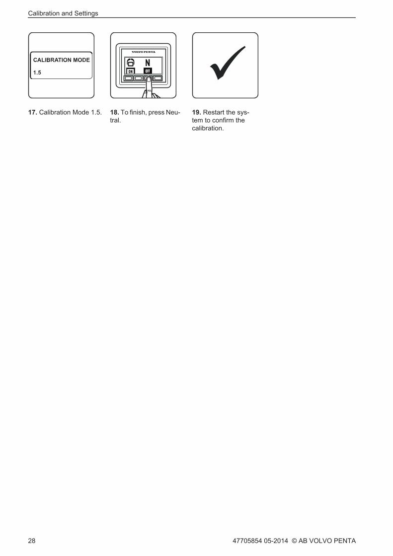
17. Calibration Mode 1.5. 18. To finish, press Neu-tral.
19. Restart the sys-tem to confirm thecalibration.
Calibration and Settings
28 47705854 05-2014 © AB VOLVO PENTA

Fuel tank settings
• If only one tank is fitted it must be configured as port side. If there are two tanks they must be calibratedseparately; begin by configuring the port side tank.
• There are two alternative ways of calibrating the fuel tank level sensor. Full tank calibration is an approx-imate method while Multi-point calibration provides more precise results.Multi-point calibration is a prerequisite for the trip computer to show fully accurate information.
• Auto-configuration must be done when the fuel tank sensor is connected.
Setting alarm level and tank volumeNOTICE! The tank must be empty.NOTICE! The alarm is switched off at the factory = 0%.
1. Switch on ignition tothe port engine.
2. System with 2.5" Dis-play.
3. Settings. 4. Confirm with OK.
5. Scroll to Fuel Tank.Confirm with OK.
6. Select port side. 7. Scroll to Fuel TankVolume.
8. Confirm with OK.
9. Warning! May only beperformed by qualifiedVolvo Penta personnel.
10. Confirm the warningmessage.
11. Set the max volume. 12. Scroll to correct value.
Calibration and Settings
47705854 05-2014 © AB VOLVO PENTA 29

13. Confirm with OK. 14. System with 2.5"Display.
15. Select Fuel TankEmpty
16. Confirm with OK.
17. Warning! May onlybe performed by quali-fied Volvo Penta per-sonnel.
18. Confirm the warningmessage.
19. Make sure the tank is empty and the sensor is cor-rectly positioned.
20. FUEL TANK PUSHWHEN EMPTY.
21. Confirm that the tankis empty.
22. Scroll to Fuel Alarm. 23. Confirm with OK.
Repeat for further fuel tankswith port ignition off.
24. Set preferred alarmlevel.
25. Confirm with OK. 26. Turn ignition off. 27. Restart the system toconfirm the calibration.
Calibration and Settings
30 47705854 05-2014 © AB VOLVO PENTA

Multi-point calibrationTo carry out multi-point calibration, fill the fuel tank to max 20% of its total capacity.NOTICE! Empty tank calibration must be concluded before multi-point calibration is performed.
Calibration is carried out in five steps: Position 1: 20% full tank. Position 4: 80% full tank.Position 2: 40% full tank. Position 5: 100% full tank.Position 3: 60% full tank.
1. Turn the ignition on. 2. System with 2.5" Dis-play.
3. Settings 4. Confirm with OK.
5. Scroll to the Fuel Tankmenu.
6. Confirm with OK. 7. Scroll to Multi-PointCalibration
8. Confirm with OK.
9. Fill the tank with thequantity specified forPos. 1
10. Wait for 10 seconds. 11. Confirm when tank isfilled to the specifiedlevel.
12. Fill to the volume speci-fied for Pos. 2. Wait 10 sec-onds.
13. Confirm when tank isfilled to the specifiedlevel.
14. Repeat the proce-dure for Pos. 3, Pos. 4and Pos 5.
15. Confirm each posi-tion.
17. Restart the system toconfirm the calibration.
Calibration and Settings
47705854 05-2014 © AB VOLVO PENTA 31

Water in oil sensorSystem with 7" Display
Applies to IPS 800–950 and IPS 1050–1200. Perform for new installations and oil change.NOTICE! Preconditions: Engine running below 1000 RPM.
1. Ignition must be on forall drivelines.
2. Go to Settings 3. EVC Settings.
4. Select Service. 5. Select Drive oil change.
6. Select driveline. 7. Select Perform. 8. Press OK to start. 9. Calibration completedsuccessfully.
10. Repeat for addi-tional engines.
11. Restart the system toconfirm the calibration.
Calibration and Settings
32 47705854 05-2014 © AB VOLVO PENTA

Slip calibration
CAUTION!This procedure requires the engine to be running. The gear will be engaged, be prepared for sudden movements.
Carry out trolling calibration for one engine at a time to avoid excessive forces. Use both levers to calibrate trippelinstallation.NOTICE! Do not perform calibration before transmission temperature has reached at least 30°C ( 86°F).NOTICE! To be performed in open water.
1.Move control to neu-tral.
2. Switch on ignition tothe port engine.
3. Press THROTTLEONLY
4. Calibration Mode 1.0.
5. Press LOW SPEED. 6. Slip calibration 6.1. 7. Start the port engine. 8. Move the levers ahead toposition 1.
WARNING!Trolling calibration is nowperformed. During calibrationgears will be engaged anddisengaged a number of times.This means the boat will move.
9. Slip calibration 6.2. 10. Calibration for trolling ahead is performed. Lasts for5 to 20 minutes.
WARNING!Trolling calibration is nowperformed. During calibrationgears will be engaged anddisengaged a number of times.This means the boat will move.
11. Slip calibration 6.3. 12. Move the leversastern to position 3.
13. Slip calibration 6.4.
Calibration and Settings
47705854 05-2014 © AB VOLVO PENTA 33

14. Calibration for trolling astern is performed.Lasts for 5 to 20 minutes.
15. Slip calibration 6.5. 16. Move control to neutral.
If this error messageappears:
SLIP CALIBRA-TION FAILED
17. Stop the engine. 18. Turn ignition off. 19. Repeat for additionalengines. Restart thesystem to confirm thecalibration.
20. Restart calibration.
Calibration and Settings
34 47705854 05-2014 © AB VOLVO PENTA

Idling speed calibration
1. Move control to neu-tral.
2. Turn the ignition on. 3. Press THROTTLEONLY
4. Indicates that cali-bration mode is acti-vated.
5. Calibration Mode 1.0. 6. Start the engines. 7. CALIBRATION IDLESPEED SET RPMappears in the display.
8. Set the preferred idlespeed using the control.D4: 700-750 rpmD6: 600-650 rpmD11: 550-700 rpmD13: 550-800 rpm
9. Confirm: PressTHROTTLE ONLY
10. Move control to neu-tral.
11. Stop the engines. 12. Restart the system toconfirm the calibration.
Calibration and Settings
47705854 05-2014 © AB VOLVO PENTA 35

Calibrating the Joystick Function
NOTICE! Calibration may be done in either direction, port or starboard, at one station.• This calibration need only be made if boat maneuvers do not correspond to joystick movements.
• Make sure there is sufficient space for maneuvering the boat.
1. Move control to neu-tral.
2. Turn the ignition on. 3. Start the engines. 4. Hold the DOCKING but-ton down for five seconds.
5. Joystick calibrationstarted.
6. Buzzer and light con-firm start of calibration.
7. Compensate boat movements with the joystick.
8. The boat must move straight abeam. 9. Hold the position andconfirm by pushingDOCKING.
10. Buzzer and light confirmend of calibration. Restartthe system to confirm thecalibration.
Calibration and Settings
36 47705854 05-2014 © AB VOLVO PENTA

Resetting calibration to the factory setting.
1. Move control to neu-tral.
2. Turn the ignition on. 3. Start the engines. 4. Hold the DOCKING but-ton down for five seconds.
5. Joystick calibrationstarted.
6. Buzzer and light con-firm start of calibration.
7. Hold the position andconfirm by pushingDOCKING.
Buzzer and light confirmend of calibration. Restartthe system to confirm thecalibration.
Calibration and Settings
47705854 05-2014 © AB VOLVO PENTA 37

Joystick Docking forceChanges the force when moving abeam. Select between Minimum, Medium and Maximum.Normal force mode and extra force mode are changed by the same factor.
1. Move control to neu-tral.
2. Turn the ignition on. 3. Connect to VODIA. (Example shows quad)
4. Select function groupSteering.
5. Configuration. 6. Dockingforce. 7. Select installation type.
8. Preconditions 9. Tap Play to start. 10. Report the resultwithin 28 days.
11. VODIA web, selectReport software.
Calibration and Settings
38 47705854 05-2014 © AB VOLVO PENTA

Calibration of Interceptor System
The IS system must be calibrated in order for it to beactivated and function as expected. Calibration is car-ried out through parameter programming with the aidof the VODIA tool.
NOTICE! It is the boatbuilder's responsibility to decideon the mode selected in settings based on how theboat is intended to handle.
Sea trial with inactive systemAlways test the boat under load conditions that repre-sent those of the end user. Assess the boat's charac-teristics such as trim, visibility, heel in turns and spray.Note the speed at which maximum trim angle is ach-ieved; this value is used for calibrating PZW.
NOTICE! PZW, PZZ and PZX only require calibrationon installations with auto function.
Preparations1. Identify the chassis numberIdentify the port driveline chassis number.
2. Order the change kitThe change kits are available in four versions, auto ormanual and two or four interceptors.
3. Download the software packageGo to Volvo Penta Partner Network and download thesoftware package (MID194) to VODIA.
4. Program the control unit, ICM.This is where the parameters PZP, PZR, PZQ and PZOare set; they need not be changed if no fault occurredwhen ordering the change kit.
NOTICE! Auto-configuration must be carried out onceprogramming is completed so that the EVC system canidentify the IS installation.
Calibration and Settings
47705854 05-2014 © AB VOLVO PENTA 39

Adjusting blade position
Check the installed position of the interceptors on thetransom, height above bottom (A). The system has apre-installed value of 10% (5 mm) (0.2") of maximuminterceptor blade extension (50 mm) (2”).Measure and take note of any deviation each intercep-tor may have from the pre-set value. Deviations meanthat the parameters below must be set.
1 PZS, Servo Module 1 Zero Offset PositionAdjusting blade start position.If the unit is installed e.g. 8 mm (0,3”) above thebottom the value must be set at 16% (16% of 50mm = 8 mm) (16% of 2” = 0.3”).
2 QAW, Servo Module 1 Working RangePre-set value 90%. The sum total of PZS and QAWmust be 100%.E.g. if PZS (start position) is changed to 16% thenQAW must be set at 84% (100%‐16% = 84%).
3 PZV, Servo Module 4 Zero Offset PositionAdjusting blade start position.If the unit is installed e.g. 8 mm (0,3”) above thebottom the value must be set at 16% (16% of 50mm = 8 mm) (16% of 2” = 0.3”).
4 QAZ, Servo Module 4 Working RangePre-set value 90%. The sum total of PZV and QAZmust be 100%.E.g. if PZV (start position) is changed to 16% thenQAZ must be set at 84% (100%‐16% = 84%).
5 PZT, Servo Module 2 Zero Offset PositionAdjusting blade start position.If the unit is installed e.g. 8 mm (0,3”) above thebottom the value must be set at 16% (16% of 50mm = 8 mm) (16% of 2” = 0.3”).
6 QAX, Servo Module 2 Working RangePre-set value 90%. The sum total of PZT and QAXmust be 100%.E.g. if PZT (start position) is changed to 16% thenQAX must be set at 84% (100%‐16% = 84%).
7 PZU, Servo Module 3 Zero Offset PositionAdjusting blade start position.If the unit is installed e.g. 8 mm (0,3”) above thebottom the value must be set at 16% (16% of 50mm = 8 mm) (16% of 2” = 0.3”).
8 QAY, Servo Module 3 Working RangePre-set value 90%. The sum total of PZU and QAYmust be 100%.E.g. if PZU (start position) is changed to 16% thenQAY must be set at 84% (100%‐16% = 84%).
P0018279
A
ICM
2:PZT QAX 4:PZV
QAZ3:PZU QAY
1:PZS QAW
P0018157
Calibration and Settings
40 47705854 05-2014 © AB VOLVO PENTA

PZY, Roll Sensor OffsetThe PZY parameter is used to enable the system togenerate a flat thwartships trim angle. If the ICM unitis correctly installed in horizontal alignment with theboat's intended horizontal plane, the value needs noadjustment.
1 Check that the control unit (ICM) is installed straightin relation to the boat's horizontal plane. Measureand note any degrees of deviation.
2 Adjust PZY with the noted deviation.
3 Perform a test run at planing speed to verify thesettings.
4 Adjust further as necessary.Positive values adjust port side up/ starboard sidedown.Negative values adjust port side down/ starboardside up.
PZW, Automatic Trim DemandSetting the boat's angle of attack.
1 Select a suitable calibration graphSelect the plot group based partly on the speed theboat has at maximum trim angle and partly on itstop speed. The plot groups are 1‐3, 4‐6, 7‐9, 10‐12,13‐15 and 16‐18 as illustrated below.
2 Set the selected graph in PZW. We recommendinitiating the test run with the graph in the middle ofthe selected plot group, i.e. 2, 5, 8, 11, 14 or 17.
3 Verification runs
NOTICE! Verification of the graph selected must bedone in test runs across the boat's full speed range.
Select how great compensation must be by testingthe boat on a selected graph. If the angle of attackmust be reduced select a higher graph number, andif it must be raised select a lower graph number.
Graph 1–3This plot group is suitable for boats whose maximumtrim angle is achieved at 12–16 knots.
Calibration and Settings
47705854 05-2014 © AB VOLVO PENTA 41

Graph 4-6This plot group is suitable for boats whose maximumtrim angle is achieved at 16-20 knots.
Graph 7-9This plot group is suitable for boats whose maximumtrim angle is achieved at 20-24 knots.
Graph 10-12This plot group is suitable for boats whose maximumtrim angle is achieved at 12–16 knots. E.g. for AQ-installations with PTA and IS collaboration.
Graph 13-15:Slower types of boat. Autotrim compensation isrequired across the boat's entire planing speed range.
Graph 16-18:Faster types of boat. Autotrim compensation isrequired across the boat's entire planing speed range.
0
45%
65%
85%
4 8 12 16 20 24 28 32
P00
1785
7
15
14
13
Kn
0
82%
4 8 12 16 20 24 28 32 36
P00
1827
5
Kn
17
16
1718
Calibration and Settings
42 47705854 05-2014 © AB VOLVO PENTA

PZZ, Turn Demand (Steering RollCompensation)
Setting how aggressively the system must compen-sate heel in connection with the application of helm,when the helmsman steers the boat with the aid of awheel or tiller (Joystick).
The illustrations above show a boat at planing speedwhen the helmsman makes a hard turn that would nor-mally cause the boat to heel. Calibration takes placeat two speeds in which boat handling in the turn isassessed according to the following:A – an increase in heel during the turn is desired.B – the boat heels to the preferred extent in the turn.C – an decrease in heel during the turn is desired.
Selecting a suitable calibration graph
1 Set graph 8 and test run the boat at a speed of20-25 knots. Assess boat handling according to A,B or C.
2 If A is selected – switch to graph 7.If B is selected – retain graph 8.If C is selected – switch to graph 9.
3 Increase speed to 30–35 knots and once againassess boat handling according to A, B or C.
4 If graph 7 assessed according to:A – switch to graph 4 (heel increases).B – retain graph 7 (heel maintained).C – switch to graph 1 (heel decreases).
5 If graph 8 assessed according to:A – switch to graph 5 (heel increases).B – retain graph 8 (heel maintained).C – switch to graph 2 (heel decreases).
6 If graph 9 assessed according to:A – switch to graph 6 (heel increases).B – retain graph 9 (heel maintained).C – switch to graph 3 (heel decreases).
Calibration and Settings
47705854 05-2014 © AB VOLVO PENTA 43

PZX, Roll Sensitivity (List Compensation)The system attempts to generate a level thwartshipstrim angle on a straight or almost straight heading atplaning speed. The value PZX is pre-set at 50, whichworks well on most planing boats, but is variable from0-100.
NOTICE! Tests and adjustments must be made atplaning speeds (>20 kn).
• Adjust PZX in increments of 2 per test run.
• Adjust the value up if the boat does not stabilizequickly enough.
• Adjust the value down if the boat continues to oscil-late at planing speed.
ODG, Trim Button Cross-couplingChanges the interceptor blade affected according tothe button depressed on the control. ODG is pre-set toOFF = Port button down moves the starboard inter-ceptor down; port button up moves the starboard inter-ceptor up and vice versa.If the opposite is preferred, set ODG to ON (cross-coupled) = port button down moves the port interceptordown; port button up moves the port interceptor up andvice versa.
NOTICE! If ODG is set to ON (cross-coupled) it shouldbe noted in the owner's manual.
Calibration and Settings
44 47705854 05-2014 © AB VOLVO PENTA

Depth Alarm
Setting for the depth alarm level on Volvo Pentas echo sounders.The setting need only be made at one helm station to be displayed on all screens at all helm stations.NOTICE! Ignition must be on for all drivelines.
1. Scroll to DepthAlarm in the Settingsmenu
2. A On/Off.B Specify level.
3. Scroll to Depth AlarmLevel.
4. Confirm.
Set the distance forthe echo-sounder/waterline orechosounder/lowestpoint to the displaydepth.
5. Select Depth Offset. 6. Set the value. 7. A Waterline.B Echo sounder.C Lowest point.
8. Distance A–B: positivevalue. Distance B–C: neg-ative value.
9. Depth Alarm: appearsand sounds every 30seconds.
10. Ceases when depthexceeds alarm level orwhen confirmed.
11. Signal fault. E.g.sensor not working.
Calibration and Settings
47705854 05-2014 © AB VOLVO PENTA 45

Autopilot
The autopilot must be configured and tuned to suit theboat. Start by running the Sea Trial Wizard which cal-ibrates the basic sensors. It is important to run the wiz-ard under circumstances and load conditions that arerepresentative for the end user.
NOTICE! If an interceptor system (IS) is installed itmust be calibrated and in auto mode before the auto-pilot is calibrated.
Autopilot buttonsUse the panel buttons to scroll through menus andconfirm settings Menu buttons function are shown onthe display.
– Return to the previous menu. If the button isheld down the display returns to the Autopilot menu.
– Menu buttons function are shown on thedisplay.
Proceed to autopilot configuration by scrolling to Set-tings> Dealer settings, autopilot.
The display will show the message WARNING!Authorized Volvo Penta OEM or dealer only.Press OK to confirm the message.
Sea Trial Wizard
The wizard calibrates the compass, adjusts the auto-pilot and sets North (if a GPS unit is connected).
CAUTION!This procedure requires the engine to be running. Thegear will be engaged, be prepared for sudden move-ments.
NOTICE! The wizard must be run in calm, open waters.
1 Scroll to Sea Trial Wizard. Press OK.
2 Set the boat's planing rpm so that it corresponds tothe boat's tachometer.Confirm with OK.
Calibration and Settings
46 47705854 05-2014 © AB VOLVO PENTA
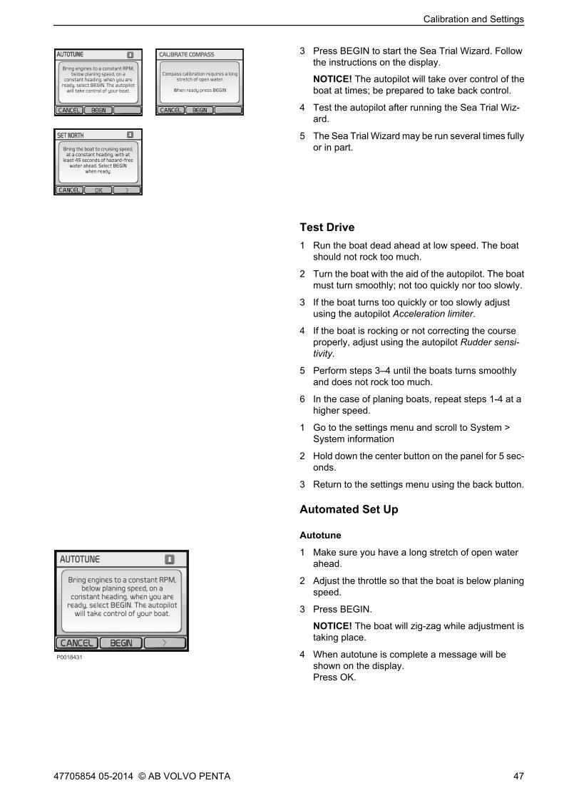
3 Press BEGIN to start the Sea Trial Wizard. Followthe instructions on the display.
NOTICE! The autopilot will take over control of theboat at times; be prepared to take back control.
4 Test the autopilot after running the Sea Trial Wiz-ard.
5 The Sea Trial Wizard may be run several times fullyor in part.
Test Drive1 Run the boat dead ahead at low speed. The boat
should not rock too much.
2 Turn the boat with the aid of the autopilot. The boatmust turn smoothly; not too quickly nor too slowly.
3 If the boat turns too quickly or too slowly adjustusing the autopilot Acceleration limiter.
4 If the boat is rocking or not correcting the courseproperly, adjust using the autopilot Rudder sensi-tivity.
5 Perform steps 3–4 until the boats turns smoothlyand does not rock too much.
6 In the case of planing boats, repeat steps 1-4 at ahigher speed.
1 Go to the settings menu and scroll to System >System information
2 Hold down the center button on the panel for 5 sec-onds.
3 Return to the settings menu using the back button.
Automated Set Up
Autotune
1 Make sure you have a long stretch of open waterahead.
2 Adjust the throttle so that the boat is below planingspeed.
3 Press BEGIN.
NOTICE! The boat will zig-zag while adjustment istaking place.
4 When autotune is complete a message will beshown on the display.Press OK.
Calibration and Settings
47705854 05-2014 © AB VOLVO PENTA 47

Calibrate Compass
1 Run the boat at a chosen course.
2 Press BEGIN and continue on that course.
3 Follow the instructions on the display and turnslowly to starboard without letting the boat heel.Run as steadily and smoothly as possible. Theautopilot will indicate if the speed maintained is toofast, too slow or just right.
4 When calibration is complete a message will beshown on the display.Press OK.
Set NorthThis setting is only shown when a GPS unit is con-nected. If a GPS is lacking set North using Fine tuningcourse under the Navigation settings menu.
1 Make sure you have at least 45 seconds of hazard-free, open water while at planing speed available.
2 Run the boat dead ahead at cruising speed.
3 When the setting is complete a message will beshown on the display.Press OK.
Calibration and Settings
48 47705854 05-2014 © AB VOLVO PENTA
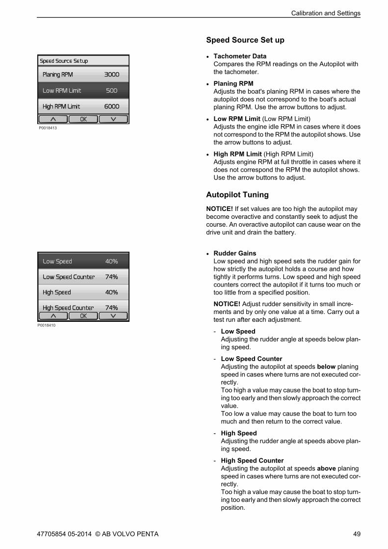
Speed Source Set up
• Tachometer DataCompares the RPM readings on the Autopilot withthe tachometer.
• Planing RPMAdjusts the boat's planing RPM in cases where theautopilot does not correspond to the boat's actualplaning RPM. Use the arrow buttons to adjust.
• Low RPM Limit (Low RPM Limit)Adjusts the engine idle RPM in cases where it doesnot correspond to the RPM the autopilot shows. Usethe arrow buttons to adjust.
• High RPM Limit (High RPM Limit)Adjusts engine RPM at full throttle in cases where itdoes not correspond the RPM the autopilot shows.Use the arrow buttons to adjust.
Autopilot Tuning
NOTICE! If set values are too high the autopilot maybecome overactive and constantly seek to adjust thecourse. An overactive autopilot can cause wear on thedrive unit and drain the battery.
• Rudder GainsLow speed and high speed sets the rudder gain forhow strictly the autopilot holds a course and howtightly it performs turns. Low speed and high speedcounters correct the autopilot if it turns too much ortoo little from a specified position.
NOTICE! Adjust rudder sensitivity in small incre-ments and by only one value at a time. Carry out atest run after each adjustment.
- Low SpeedAdjusting the rudder angle at speeds below plan-ing speed.
- Low Speed CounterAdjusting the autopilot at speeds below planingspeed in cases where turns are not executed cor-rectly.Too high a value may cause the boat to stop turn-ing too early and then slowly approach the correctvalue.Too low a value may cause the boat to turn toomuch and then return to the correct value.
- High SpeedAdjusting the rudder angle at speeds above plan-ing speed.
- High Speed CounterAdjusting the autopilot at speeds above planingspeed in cases where turns are not executed cor-rectly.Too high a value may cause the boat to stop turn-ing too early and then slowly approach the correctposition.
Calibration and Settings
47705854 05-2014 © AB VOLVO PENTA 49

Too low a value may cause the boat to turn toomuch and then return to the correct position.
• Acceleration LimiterLimits how quickly the autopilot yaws.Increase the value if the boat yaws too quickly.Reduce the value if the boat yaws too slowly.
Navigation Set up
• Fine Heading AdjustmentThis setting is only shown when no GPS unit is con-nected.
1 Set North using a hand-held compass.
2 Adjust North on the autopilot until it correspondswith North on the magnetic compass.
3 Confirm with OK.
• NMEA Set up
- NMEA ChecksumIf a GPS unit connected to NMEA 0183 calculatesan erroneous checksum it is possible to disablechecksum monitoring.
NOTICE! When the function is disabled data reli-ability may be at risk.
- Reversed XTEIf the connected GPS unit sends an erroneousheading signal (port confused with starboard) itcan be corrected by switching the setting on oroff.
• Navigation GainSetting how aggressively the autopilot counteractsdeviations from a course set in the plotter.Too high a value may cause the boat to swing overthe course. Too low a value may cause the autopilotto react too slowly to deviations from the course.
• Navigation Trim GainFine tuning of acceptable course deviations. Onlyadjust this value if Navigation search has beenadjusted.Too high a value may overcompensate for devia-tions from the set course. Too low a value allowsexcessive deviations from the set course.
Calibration and Settings
50 47705854 05-2014 © AB VOLVO PENTA

Volvo Penta Glass Cockpit,calibrationNOTICE! Applies only to EVC-E2.All EVC functions are integrated in the touch screen.
Select Settings in the main menu to reach calibrationand settings.
Select My Vessel for calibration and settings. Followthe instructions shown on screen.
Select Home to return to the main menu.
GARMIN
SettingsEngage Waypoints Meny SOS
Home
Info Mark
P 1882000
GARMIN
My VesselSettings
SOS
System
Preferences
Communications
Alarms
My Vessel
Other Vessels
Back
Meny HomeWaypoints Engage
P 1993900
Info Mark
Calibration and Settings
47705854 05-2014 © AB VOLVO PENTA 51
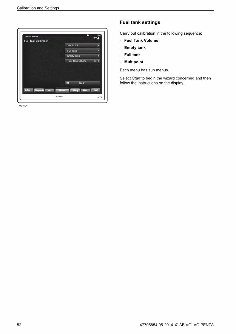
Fuel tank settings
Carry out calibration in the following sequence:
- Fuel Tank Volume
- Empty tank
- Full tank
- Multipoint
Each menu has sub menus.
Select Start to begin the wizard concerned and thenfollow the instructions on the display.
GARMIN
My VesselFuel Tank Calibration
SOS
Multipoint
Full Tank
Empty Tank
Fuel Tank Volume
Back
Meny HomeWaypoints 0.0m
P 1994400
Info Mark
0 L
Calibration and Settings
52 47705854 05-2014 © AB VOLVO PENTA

Autopilot calibrationThe autopilot must be configured to suit the boat. Startby running the Sea Trial Wizard which calibrates thebasic sensors. It is important that the wizard be rununder circumstances and load conditions that are rep-resentative for the end user.
NOTICE! If an interceptor system (IS) is installed itmust be calibrated and in auto mode before the auto-pilot is calibrated.
Autopilot menusScroll to the main autopilot menu: Home> Settings> MyVessel> Dealer Autopilot setup
The display will show the message WARNING!Authorized Volvo Penta dealer or OEM only.Confirm the message: Press OK.
The autopilot main view shows the followingchoices:
- Sea Trial Wizard
- Automated Set Up
- Speed Source Set Up
- Autopilot Tuning
- Restore Defaults
Each menu has sub menus.
Select Start to begin the wizard concerned and thenfollow the instructions on the display.
Calibration and Settings
47705854 05-2014 © AB VOLVO PENTA 53
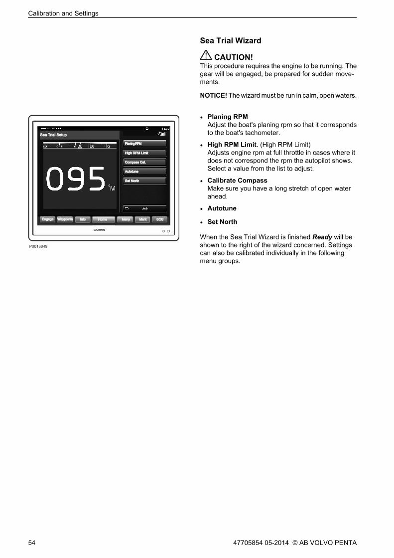
Sea Trial Wizard
CAUTION!This procedure requires the engine to be running. Thegear will be engaged, be prepared for sudden move-ments.
NOTICE! The wizard must be run in calm, open waters.
• Planing RPMAdjust the boat's planing rpm so that it correspondsto the boat's tachometer.
• High RPM Limit. (High RPM Limit)Adjusts engine rpm at full throttle in cases where itdoes not correspond the rpm the autopilot shows.Select a value from the list to adjust.
• Calibrate CompassMake sure you have a long stretch of open waterahead.
• Autotune
• Set North
When the Sea Trial Wizard is finished Ready will beshown to the right of the wizard concerned. Settingscan also be calibrated individually in the followingmenu groups.
Planing RPMPlaning RPM
GARMIN
HomeEngage Info Mark SOS
Planing RPM
High RPM Limit
Compass Cal.
Autotune
Set North
Sea Trial Setup
Waypoints Meny
P0018849
Calibration and Settings
54 47705854 05-2014 © AB VOLVO PENTA

Automated Setup
• Autotune
NOTICE! If set values are too high the autopilot maybecome overactive and constantly seek to adjustthe course. An overactive autopilot can cause wearon the drive unit and drain the battery.
Run the boat dead ahead at low speed. Start thewizard. The boat will change course in a cyclic zig-zag for around 15 seconds.
• Compass CalibrationMake sure you have at least 45 seconds of hazard-free water ahead.
• Set NorthMake sure you have at least 45 seconds of hazard-free water ahead.
• Fine Heading Adjustment
Speed Source Set Up• Low RPM Limit. (Low RPM Limit)
Adjusts the engine idle rpm in cases where it doesnot correspond to the rpm the autopilot shows.
• High RPM Limit. (High RPM Limit)Adjusts engine rpm at full throttle in cases where itdoes not correspond the rpm the autopilot shows.
• Planing RPMAdjusts the boat's planing rpm in cases where theautopilot does not correspond to the boat's actualplaning rpm.
Planing RPMPlaning RPM
GARMIN
HomeEngage Info Mark SOS
Set Nor th
Automated Setup
Waypoints Meny
P0018825
Autotune
Compass Cal.
Fine Heading Adj.
Planing RPMPlaning RPM
GARMIN
HomeEngage Info Mark SOS
Set Nor th
Speed Source Setup
Waypoints Meny
P0018878
Beginning
100 rpm
200 rpm
300 rpm
400 rpm
500 rpm
Next pageV V
Calibration and Settings
47705854 05-2014 © AB VOLVO PENTA 55

Autopilot TuningUse the Up and Down buttons to adjust the value.
• Acceleration Limiter
Limits how quickly the autopilot yaws. Increase thevalue if the boat yaws too quickly. Reduce the value ifthe boat yaws too slowly.
• Rudder Gains
Low speed and high speed set rudder angle to howstrictly the autopilot holds a course and how tightlyit performs turns. Low speed and high speed coun-ters correct the autopilot if it turns too much or toolittle from a specified position.
NOTICE! Adjust rudder sensitivity in small incrementsand by only one value at a time. Carry out a test runafter each adjustment.
Low SpeedAdjusting the rudder angle at speeds below planingspeed.
Low Speed CounterAdjusting the autopilot at speeds below planingspeed in cases where turns are not executed cor-rectly.Too high a value may cause the boat to stop turningtoo early and then slowly approach the correctvalue.Too low a value may cause the boat to turn too muchand then return to the correct value.
High SpeedAdjusting the rudder angle at speeds above planingspeed.
High Speed CounterAdjusting the autopilot at speeds above planingspeed in cases where turns are not executed cor-rectly.Too high a value may cause the boat to stop turningtoo early and then slowly approach the correct posi-tion.Too low a value may cause the boat to turn too muchand then return to the correct position.
GARMIN
HomeEngage Info Mark SOSWaypoints Meny
P0018826
Autopilot Tuning Accelerat ion Limit er62%
100%
90%
80%
70%
60%
50%
40%
30%
20%
10%
0%
Up
Down
Back
Calibration and Settings
56 47705854 05-2014 © AB VOLVO PENTA

AAcknowledge message.............................................. 7Add e-Key................................................................. 24Alarm handling........................................................... 7Auto configuration, 4" display................................... 18Auto configuration, 7" display................................... 19Auto configuration, analog lever............................... 21Auto configuration, quadruple installation................ 16Auto configuration, triple installation......................... 14Auto configuration, twin installation.......................... 12Autopilot................................................................... 46CCalibrating the Joystick Function.............................. 36Calibration and Settings............................................. 2Calibration of Interceptor System............................. 39Controls and Steering System.................................... 5DDepth Alarm............................................................. 45Displays...................................................................... 3Ee-Key.......................................................................... 2FFuel tank settings..................................................... 29GGeneral....................................................................... 2IIdling speed calibration............................................. 35IPS Calibration........................................................... 8LLanguage................................................................. 22Lever calibration, analog lever with stand-aloneHCU.......................................................................... 27Lever Calibration, top mounted lever....................... 25SSlip calibration.......................................................... 33UUnits......................................................................... 23VVolvo Penta Glass Cockpit, calibration.................... 51WWater in oil sensor.................................................... 32
Alphabetical index
47705854 05-2014 © AB VOLVO PENTA 57


4770
5854
Eng
lish
05-
2014
AB Volvo PentaSE-405 08 Göteborg, Sweden
www.volvopenta.com