Embed Size (px)
Citation preview
CALIBRATING CAMAC ANALOG-DIGITAL CONVERTERS
V. S. Paramonov, S. N. Ryndov, G. A. Solov'ev, and G. M. Shmulevich
UDC 65.012.7.011.56: 53.087.92
Personal microcomputers of the DVK family are increasingly used for automatic deter- mination of metrological characteristics (MCs) of CAMAC modules used in scientific research systems. Computers of this class are employed in automatic measuring systems when the appli- cation of more powerful computers is economically unjustified. Moreover, while offering practically all functional possibilities of minicomputers, they are much less expensive, occupy less space, and are better adapted for individual applications.
All DVK sets are based on the modular principle and offer a wide selection of peripher- al devices such as displays, floppy-disk drives, a matrix printer, and plotter. If neces- sary, they can be easily supplemented with other devices and modules. The real-time OS DVK operating system, included in the supplied mathematical software, does not need highly skilled operators and is capable of organizing computation procedures in systems having 16-56 Kbytes of main memory [i].
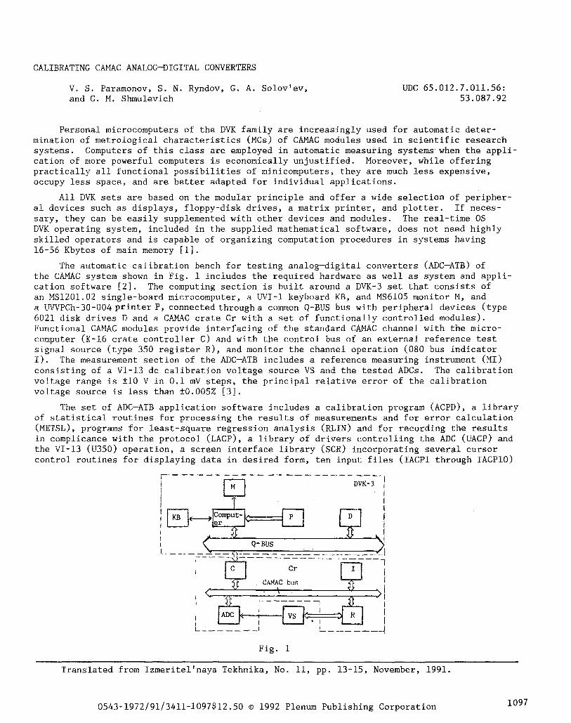
The automatic calibration bench for testing analog-digital converters (ADC-ATB) of the CAMAC system shown in Fig. 1 includes the required hardware as well as system and appli- cation software [2]. The computing section is built around a DVK-3 set that consists of an MS1201.02 single-board microcomputer, a UVI-I keyboard KB, and MS6105 monitor M, and a UVVPCh-30-004 printer P, connected through a common Q-BUS bus with peripheral devices (type 6021 disk drives D and a CAMAC crate Cr with a set of functionally controlled modules). Functional CAMAC modules provide interfacing of the standard CAMAC channel with the micro- computer (K-16 crate controller C) and with the control bus of an external reference test signal source (type 350 register R), and monitor the channel operation (080 bus indicator I). The measurement section of the ADC-ATB includes a reference measuring instrument (MI) consisting of a VI-13 dc calibration voltage source VS and the tested ADCs. The calibration voltage range is • V in 0.i mV steps, the principal relative error of the calibration voltage source is less than • [3].
The set of ADC-ATB application software includes a calibration program (ACPD), a library of statistical routines for processing the results of measurements and for error calculation (METSL), programs for least-square regression analysis (RLIN) and for recording the results in complicance with the protocol (LACP), a library of drivers controlling the ADC (UACP) and the VI-13 (U350) operation, a screen interface library (SCR) incorporating several cursor control routines for displaying data in desired form, ten input files (IACPI through IACPI0)
DVK- 3 1 J
< L Q-BUS ~1 ~ Cr I
I <
CAMAC bus
>I ,
I
Fig. 1
Translated from Izmeritel'naya Tekhnika, No. ii, pp. 13-15, November, 1991.
0543-1972/91/3411-1097512.50 �9 1992 Plenum Publishing Corporation 1097
and one data file (INFACP) that store data on the types of ADCs that can be tested in the described calibration bench. All programs are written in ASSEMBLER and FORTRAN-4 in the RTIISJ, version 5.02, operating environment.
The ACPD program occupies 28 Kbytes of main memory. The program is easily adaptable to experimental conditions. This is done by using the screen editor to change the appropri- ate input file. In addition, ten available input files enable the user to adapt the ADC-ATB to ten additional types of CAMAC ADCs.
The ADC-ATB provides the following operation modes: prompting, input data checking, adjustment, diagnosis, reporting, reselection, and program exit. Operating modes are chosen interactively from a menu. The monitor displays the menu every time an operating mode is terminated. Such an ADC-ATB operating procedure has been found to be most simple and effi- cient from a practical point of view.
After the program is started, the user enters the calibration date, his password, the number of the ADC module in the crate, and the converter properties. The computer reads the INFACP data file and the user is offered a menu from which to select the type of the ADC to be calibrated.
The number of the ADC selected corresponds to the number of the opened file containing information on the measured mode and range switching codes, the admissible principal error, and the codes for generating the required test signal levels. Next, the user is presented with a main menu from which to choose the desired operation mode. The function of the ADC- ATB is governed by the mode selected and by the particular operation being executed. For example, in the prompting mode the user is offered the most efficient procedure for checking the ADC metrological characteristics and is reminded to make the necessary MI connections. In the input data checking mode, the data read from an input file are displayed on the screen as a table enabling the user to check the correctness of displayed data and his choice.
The adjustment mode is unique in the ADC-ATB operation since it allows continuous mea- surement of the input signal within the selected range displaying the results on the screen. The user can manually change the input test signals within the desired range by successively adjusting the signal according to a prepared procedure. This mode also can be used for rechecking the ADC metrological characteristics at doubtful points.
When the ADC-ATB operates in the calibration mode, the monitor displays a message re- minding that the voltage applied to the VI-13 must be positive (since the VI-13 calibrator has no facility of automatically switching the polarity of its output voltage). The dc test signal from the voltage calibrator operating in a remote control mode is then applied to the ADC input. The test signal level (U0i) at the i-th point and the VI-13 calibrator range are determined by a 32-bit control word generated at the type 350 register output according to the code table. The next test signal level is generated by adding one voltage quantum to the preceding signal level.
The numerical values of voltage quanta for every ADC measuring range and their corre- sponding codes are stored in the input file. The initial test signal level on all ranges is zero. After a program-generated delay (-5 sec), the ADC is started and the result of measurement is read. The input voltage is measured 20 times at every point. The first ten readings are rejected to avoid gross errors due to ADC transients. The result (Uav, i) at the i-th point is taken as the arithmetic mean of these measurements.
The prncipal absolute ADC error at the i-th point is defined as &i = Uav,i,- U0i- To improve the efficiency of detecting faulty ADCs, a tolerance check is carried out at every i-th point, i.e., the error is checked to lie within the tolerance limits. The measurement range as well as U0i, Uav~i, and A i are displayed on the screen, enabling the user visually to check the calibration process. The results of measurements exceeding the tolerance limits are marked by the symbol "?."
The user can at any time interrupt the calibration process and return to the main menu.
The result of the calibration procedure is an array of numerical data, including the values of U0i, Uav,i, and &i at all checked points. Measurements are taken for positive and negative test signal levels. The obtained data array is used in subsequent diagnostic and documentation modes for regression analysis and printing out the calibration protocol. In addition, the maximum error &imax is computed and is recorded in the calibration proto- col. The calibration process is fully automatic except for polarity switching.
1098
The ADC-ATB operation in the diagnostic mode is essentially the same as in the calib- ration mode. The difference is that the array of numerical data obtained during calibration is initially used to compute the unbiased ADC characteristic. This eliminates the shift of the static characteristic caused by the drift of zero and the transfer constant in I the given mode and measurement range. This is achieved by linear approximation of the form Uav,i = AU0i + B. The coefficients A and B are computed in the RLIN module by the method of least squares. The unbiased results of measurement (Uav,i - B)/A obtained at the i-th point are then compared with the reference value (U0i) and the absolute error of the unbiased result A i' = (Uav, i - B)/A - U0i is computed. This operation should be executed several times during a certain time interval. Comparing the errors A i and A i' it is possible to establish how efficiently the proposed method corrects the systematic error of a given ADC. This operation of checking the metrological characteristics of an ADC is justified because it allows the operator to work out specific recommendations on the use of ADCs in measure- ment systems. After the error A i' at the i-th point has been determined, the program module (METSL) uses the results of ten measurements to compute an estimate of the standard devia- tion (SD) for a confidence coefficient P = 0.95.
The results of measurements (for positive input signals only) are displayedlon the monitor. After measurements are completed in each range the screen displays the linear regression equation and the maximum SD estimate.
In the documentation mode the user can request a hard copy of the ADC calibration pro- tocol. Printing of the protocol is controlled by a program module (LACP) that can provide a full or abbreviated protocol and a certificate that the checked ADC is unusable. The form of the protocol is selected by microcomputer request. The printout of a full protocol contains all essential ADC registration data (type, serial number, number of certificate, etc.) and the complete numerical data array obtained in the calibration mode. Besides ADC registration data, the abbreviated protocol displays on the screen the maximum and admis- sible errors on all ADC measurement ranges. If the results are negative, the test bench outputs a typical form certifying that the tested instrument is unusable.
The reselection mode returns the user to the initial interactive dialog and requests information on the next ADC to be tested. This mode is especially useful when several ADCs in a crate are to be calibrated with the ADC-ATB since there is no need to turn off the computer and to reload the program.
The program exit mode is the last one. Its execution resets the VI-13 calibrator out- put voltage to zero and returns the set to the microcomputer operating environment.
The continuous operating time of the ADC-ATB is not less than 8 h. Operating conditions are established in less than 1 h.
The ADC-ATB is designed as a 800 • 800 x 1800 mm mobile rack of the standard "Vishnya" type. Considerable experience has been gained in the adjustment and analysis of metrologi- cal characteristics of 701A, 712, and similar ADCs of the CAMAC standard. If no hard pro- tocol copy is requested, the ADC calibration time is not more than 15 min. The operating instructions developed ensure easy mastering of the test bench and describes how the field ADC-ATB applications can be extended.
The ADC-ATB can be used in metrological services in various branches of the national economy where measuring systems based on CAMAC standards are employed.
LITERATURE CITED
i. V.S. Kokorin, A. A. Popov, and A. A. Shishkevich, Personal Computers [in Russian], Vysshaya Shkola, Moscow (1988).
2. B.M. Blekhter and M. M. Kluzman, Izmer. Tekh., No. 4, 60 (1986). 3. Catalog of Products of the Communications Industry. Electronic Measurement Instru-
ments [in Russian], TsOONTI EKOS, Moscow (1985).
1099