Embed Size (px)
Citation preview
BULETINUL INSTITUTULUI POLITEHNIC DIN IAŞI Publicat de
Universitatea Tehnică „Gheorghe Asachi” din Iaşi Volumul 65 (69), Numărul 3, 2019
Secţia CONSTRUCŢII. ARHITECTURĂ
CALCULUS OPTIMIZATION OF A STRENGTHENING METHOD FOR A REINFORCED CONCRETE BEAM USING CARBON FIBRE REINFORCED POLYMER COMPOSITES
BY
ALEXANDRU FILIP1,* and DANIEL COVATARIU2
Technical University “Gh. Asachi” of Iaşi,
1Doctoral School of the Faculty of Civil Engineering and Building Services, 2Faculty of Civil Engineering and Building Services
Received: August 5, 2019 Accepted for publication: September 10, 2019
Abstract. In recent years, the need to rehabilitate / consolidate the existing
built-up fund has become of particular importance for many reasons (extension of the construction exploitation period, economic considerations, etc.).
This paper presents the results of a numerical investigation of flexural and shear strengthening of reinforced concrete (RC) roof elements (T – section beams) with externally bonded Carbon Fibre Reinforced Polymer (CFRP) strips and sheets of a water tank.
The assessment has been conducted using two software design programs. Firstly, the input data values have been collected on the basis of an experimental program. The numerical evaluation of the reinforced concrete structural element has been calculated as a simply supported beam using SCIA Engineer software program, by FEM (Finite Element Method), in order to determine the maximum values of the internal efforts (bending moment, shear force) in different load combinations.
Subsequently, based on the results obtained, the design of the consolidation solutions using CFRP has been realised with the Sika® Carbodur® FRP Design program.
*Corresponding author; e-mail: [email protected]
90 Alexandru Filip and Daniel Covatariu
This program allows the design of flexural strengthening (using the maximum value of the bending moment) to determine the dimensions of CFRP strip and the design of shear strengthening (using the maximum value of the shear force) to determine the dimensions and the number of layers of CFRP sheet.
In the case of shear strengthening, it has been calculated two types of application of CFRP on the structural elements: continuous jacketing and discrete strips. The obtained results for both variants present some advantages and disadvantages. In both situations, the results are valid and the design is made according to the norms, conclude the fact that the use of CFRP (Carbon Fibre Reinforced Polymer) represents an effective consolidation method which can be used to repair and strengthen damaged/deteriorated beams.
Keywords: Finite Element Method; numerical evaluation; carbon fibre reinforced polymer; roof element; concrete.
1. Introduction The need for structural improvement of the existing built-up fund is of
significant importance compared to recently built structures. Several causes can lead to degradation/deterioration to the various structural elements (beams, columns, etc.), such as:
– the quality of the materials used; – design and/or execution errors; – inappropriate exploitation of existing objectives; – exceptional loads; – action of the aggressive environmental agents (freeze-thaw cycles,
acid rains etc.). Due to the degradation/deterioration of structural elements, the
structural consolidation procedure represents a current problem nowadays. Bringing an existing construction objective to the requirements of the current rules can be solved by adopting an appropriate consolidation system (Karzad et al., 2017).
Therefore, the consolidation of the damaged structures is essential in order to maintain and extend the service life.
2. Description of the Structural Element
The analysed construction is a ground water tank made of reinforced concrete having a capacity of 5,000 m3. It was built in the 1980s and it is still in exploitation, providing the necessary water for the Miroslava village and the Nicolina neighbourhood in Iaşi, Iaşi county.

Bul. Inst. Polit. Iaşi, Vol. 65 (69), Nr. 3, 2019 91
Due to the constant exploitation and possible execution errors, severe degradations/deteriorations (reinforcement corrosion, expulsion of the concrete layer, cracks) were identified at the level of the roof elements (Fig. 1).
Fig. 1 − Degraded roof elements At the top, the tank was closed with reinforced concrete T-shaped (Table 1) roof elements (Fig. 2) which are radially disposed, supporting one end on the top of the wall and the other on the central pillar cap.
Table 1 Geometry Input Data
Input data Geometrical characteristics 1. Type of section T – reinforced concrete; 2. Sectional dimensions (B H) (25 – 188) 51 [cm] 3. Web thickness Variable: 11,...,14 [cm] 4. Flange thickness Variable 5,...,8 [cm]
Fig. 2 − Lateral view of the structural element.
92 Alexandru Filip and Daniel Covatariu
Therefore, in order to increase the durability of the structure, consolidation solutions using CFRP (Carbon Fibre Reinforced Polymer) composite materials have been computed. A numerical calculus based on an experimental program (laboratory tests) and a software analysis by FEM (Finite Element Method) was performed.
In the initial stage of the analysis, the mechanical characteristics of the materials has been collected from the experimental tests by using destructive methods, the compressive strength is fck,cube = 15 N/mm2, corresponding to the concrete class C12/15.
The materials used for the construction of the structural elements are illustrated in Table 2.
Table 2 Material Input Data
Material Type / Class 1. Concrete C12/15 2. Reinforcement OB37, STNB, TBP12
3. Numerical Analysis by FEM
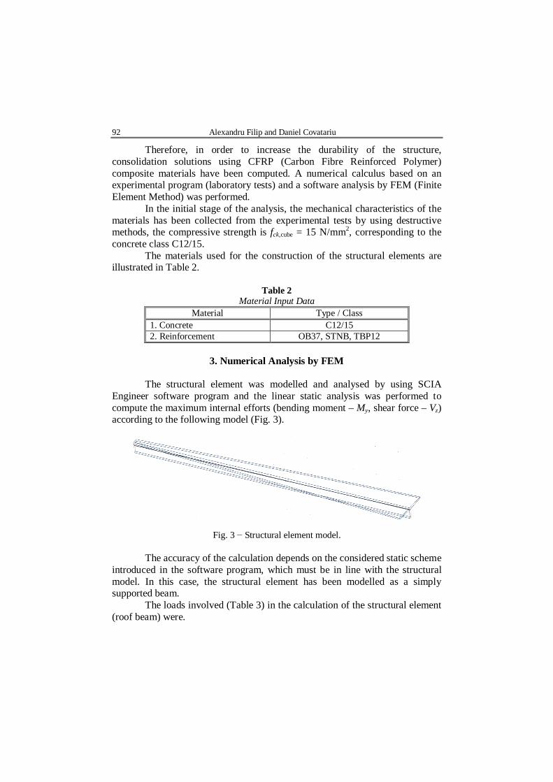
The structural element was modelled and analysed by using SCIA
Engineer software program and the linear static analysis was performed to compute the maximum internal efforts (bending moment – My, shear force – Vz) according to the following model (Fig. 3).
Fig. 3 − Structural element model.
The accuracy of the calculation depends on the considered static scheme introduced in the software program, which must be in line with the structural model. In this case, the structural element has been modelled as a simply supported beam.
The loads involved (Table 3) in the calculation of the structural element (roof beam) were.
Bul. Inst. Polit. Iaşi, Vol. 65 (69), Nr. 3, 2019 93
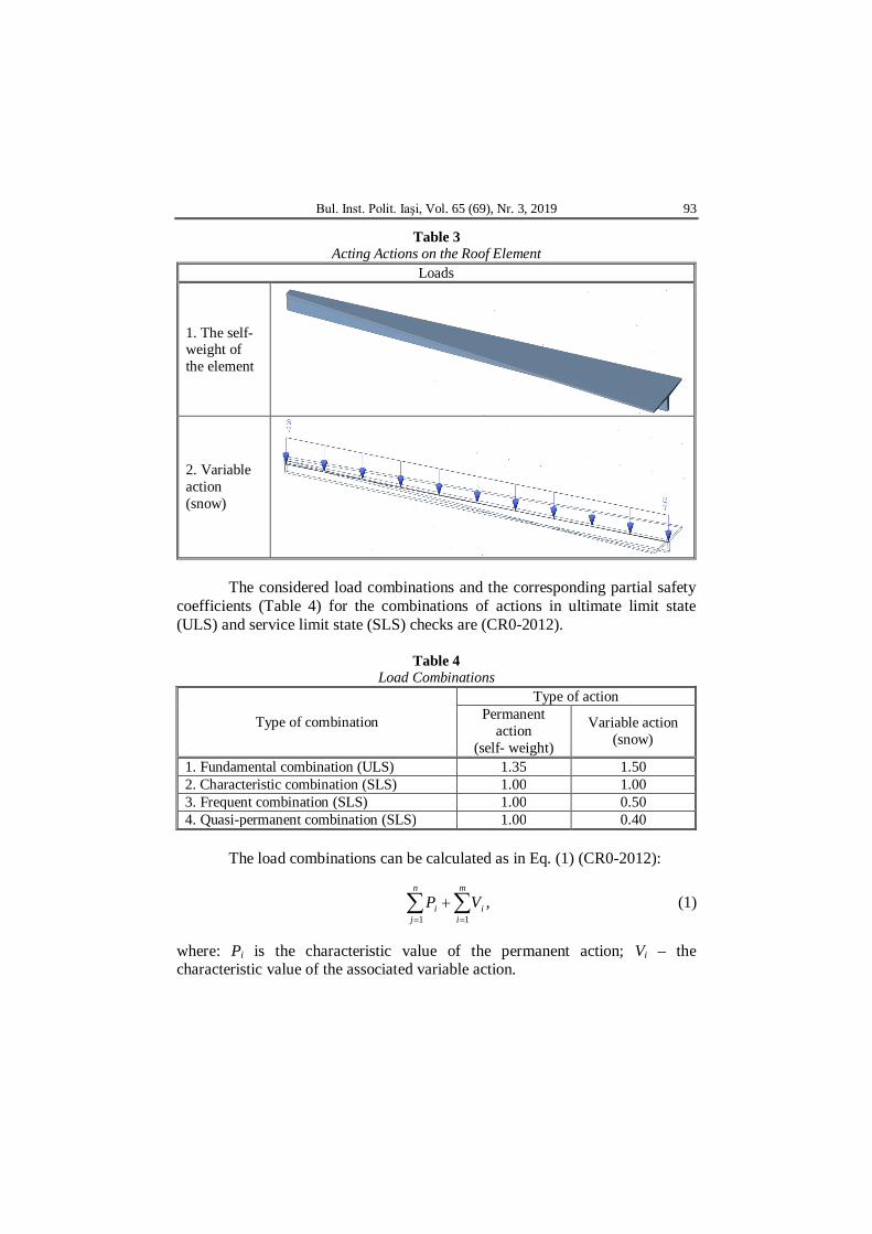
Table 3 Acting Actions on the Roof Element
Loads
1. The self-weight of the element
2. Variable action (snow)
The considered load combinations and the corresponding partial safety coefficients (Table 4) for the combinations of actions in ultimate limit state (ULS) and service limit state (SLS) checks are (CR0-2012).
Table 4 Load Combinations
Type of combination
Type of action Permanent
action (self- weight)
Variable action (snow)
1. Fundamental combination (ULS) 1.35 1.50 2. Characteristic combination (SLS) 1.00 1.00 3. Frequent combination (SLS) 1.00 0.50 4. Quasi-permanent combination (SLS) 1.00 0.40
The load combinations can be calculated as in Eq. (1) (CR0-2012):
1 1
,n m
i ij i
P V
(1)
where: Pi is the characteristic value of the permanent action; Vi – the characteristic value of the associated variable action.
94 Alexandru Filip and Daniel Covatariu
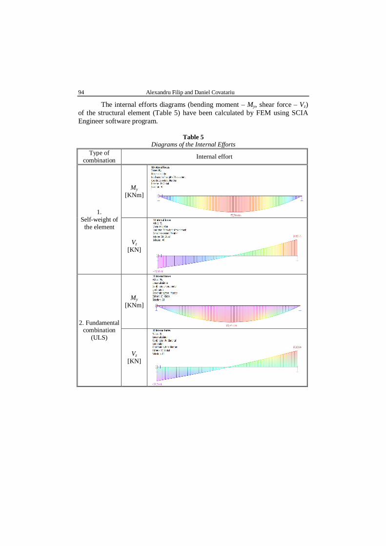
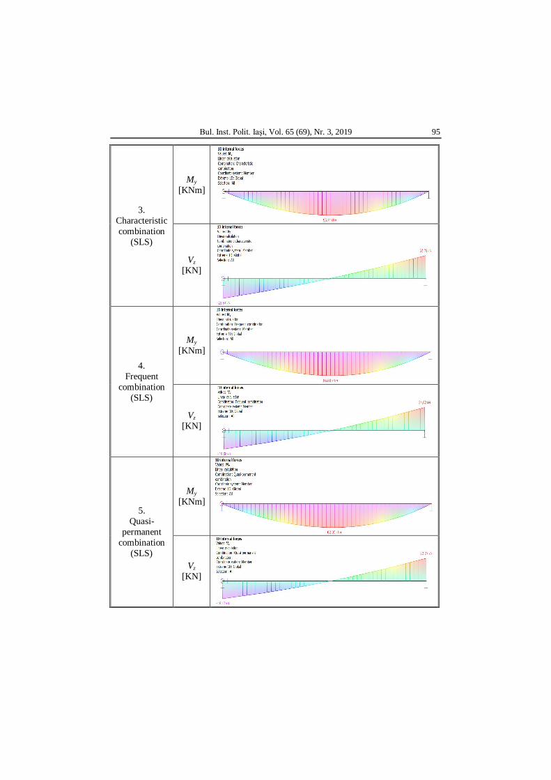
The internal efforts diagrams (bending moment – My, shear force – Vz) of the structural element (Table 5) have been calculated by FEM using SCIA Engineer software program.
Table 5 Diagrams of the Internal Efforts
Type of combination Internal effort
1. Self-weight of
the element
My [KNm]
Vz [KN]
2. Fundamental combination
(ULS)
My [KNm]
Vz [KN]
Bul. Inst. Polit. Iaşi, Vol. 65 (69), Nr. 3, 2019 95
3. Characteristic combination
(SLS)
My [KNm]
Vz [KN]
4. Frequent
combination (SLS)
My [KNm]
Vz [KN]
5. Quasi-
permanent combination
(SLS)
My [KNm]
Vz [KN]

96 Alexandru Filip and Daniel Covatariu
After the analysis based on the numerical modelling was performed, the maximum values of the internal efforts (Table 6), have been quantified. Subsequently, the calculation and the checking of the consolidation solution using FRP composites has been realized using the software program Sika® CarboDur® FRP Design.
Table 6 Maximum Internal Efforts
Type of combination Internal effort
My, max [KNm]
Vz, max [KN]
1. Self-weight of the element 57.79 21.83 2. Fundamental combination (ULS) 185.43 66.68 3. Characteristic combination (SLS) 93.41 33.78 4. Frequent combination (SLS) 66.68 24.82 5. Quasi-permanent combination (SLS) 62.05 23.27
4. Numerical Analysis by Sika® Carbodur® FRP Design
Sika® Carbodur® FRP Design is a software program for the design of consolidation solutions using Sika CarboDur Composite strengthening systems in order to increase the flexural, shear and confinement strength of reinforced concrete structures and elements (Sika® CarboDur®).
For the considered case study, it has been computed the flexural and the shear strengthening (in two cases: continuous jacket and discrete strips).
4.1. Flexural strengthening
The flexural strength of a reinforced concrete beam can be extensively increased by application of carbon (CFRP), plates/sheets adhesively bonded to the tensioned face of the beam (Fig. 4) (Soliman, 2018).
Fig. 4 − CFRP strip bonding.

Bul. Inst. Polit. Iaşi, Vol. 65 (69), Nr. 3, 2019 97
Carbon Fibre Reinforced Polymers (CFRP) are being increasingly used in rehabilitation and consolidation of concrete structures and elements, since low cost comparison with other types of fibres are generally high strength-to-weight ratio, corrosion and fatigue resistance (Murali et al., 2011).
Taking into consideration the maximum values of the internal efforts and the geometric characteristics of the structural element, the following numerical calculus has been performed (Table 7).
Table 7 Flexural Strengthening Results
Type of combination Internal effort
Maximum value
1. Fundamental combination
(ULS)
Resisting design moment before strengthening – Mrd,0 [KNm] 140.43
Required FRP cross section – Af [mm²] 38.12 Applied FRP cross section – Af [mm²]; 60.00 Resisting design moment after strengthening – Mrd [KNm]; 211.20
Degree of strengthening – Mrd / Mrd,o 1,504
2. Characteristic combination
(SLS)
Moment capacity before strengthening – Mser,r,o [KNm] 126.69
Required FRP cross section – Af [mm²] 0.00 Applied FRP cross section – Af [mm²]; 60.00 Moment capacity - Mser,r [KNm]; 133.50 Steel stress - fs11 [N/mm²]; 352.00 Concrete stress - σc [N/mm²]; 6.12
3. Quasi-permanent
combination (SLS)
Moment capacity before strengthening – Mser,r,o [KNm] 124.52
Required FRP cross section – Af [mm²] 0.00 Applied FRP cross section – Af [mm²]; 60.00 Moment capacity – Mser,r [KNm]; 132.35 Steel stress – fs11 [N/mm²]; 352.00 Concrete stress – σc [N/mm²]; 4.73
The flexural strengthening is made according by Fundamental
Combination at the Ultimate Limit State, the final required fibre reinforced polymer cross section having the value Af = 38.12 mm2. Dimensions of the applied FRP:
– width: bf = 50 mm; – thickness: tf = 1.2 mm; – number of strips: n = 1; – applied FRP cross section: Af = 60.00 mm².
98 Alexandru Filip and Daniel Covatariu
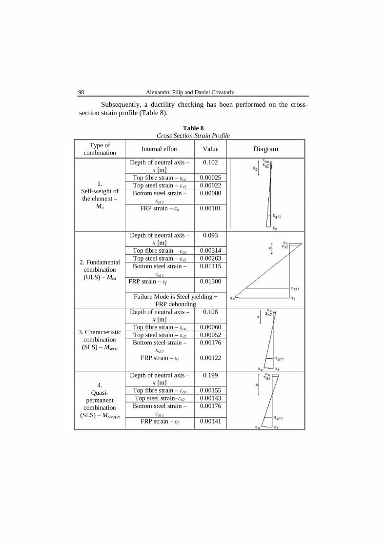
Subsequently, a ductility checking has been performed on the cross-section strain profile (Table 8).
Table 8
Cross Section Strain Profile Type of
combination Internal effort Value Diagram
1. Self-weight of the element –
Mo
Depth of neutral axis – x [m]
0.102
Top fibre strain – εco 0.00025 Top steel strain – εs2 0.00022 Bottom steel strain –
εs11 0.00080
FRP strain – εo 0.00101
2. Fundamental combination (ULS) – Mrd
Depth of neutral axis – x [m]
0.093
Top fibre strain – εco 0.00314 Top steel strain – εs2 0.00263 Bottom steel strain –
εs11 0.01115
FRP strain – εf
0.01300
Failure Mode is Steel yielding + FRP debonding
3. Characteristic combination (SLS) – Mser,r
Depth of neutral axis – x [m]
0.108
Top fibre strain – εco 0.00060 Top steel strain – εs2 0.00052 Bottom steel strain –
εs11 0.00176
FRP strain – εf 0.00122
4. Quasi-
permanent combination
(SLS) – Mser,q-p
Depth of neutral axis – x [m]
0.199
Top fibre strain – εco 0.00155 Top steel strain–εs2 0.00143
Bottom steel strain – εs11
0.00176
FRP strain – εf 0.00141
Bul. Inst. Polit. Iaşi, Vol. 65 (69), Nr. 3, 2019 99
Ductility checking for the Ultimate Limit State: – ζ = x/(h – d11) = 0.220 – maximum ζ = 0.45 → ductility requirement is satisfied. From the numerical analysis and the ductility checking, it has been
resulted that for the flexural strengthening it will be used as a consolidation solution a CFRP strip having cross-sectional dimensions (B tf): 50 1.2 mm.
4.2. Shear strengthening
In the situation when the shear strengthening calculation is performed, the CFRP material in this method of installation can take the form of discrete strips spaced at some interval defined by the design engineer or it can take the form of a continuous jacketing in which the entire concrete element is covered with a wrap of CFRP material. (Atif et al., 2007).
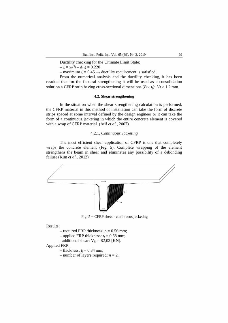
4.2.1. Continuous Jacketing
The most efficient shear application of CFRP is one that completely wraps the concrete element (Fig. 5). Complete wrapping of the element strengthens the beam in shear and eliminates any possibility of a debonding failure (Kim et al., 2012).
Fig. 5 − CFRP sheet - continuous jacketing
Results: – required FRP thickness: tf = 0.56 mm; – applied FRP thickness: tf = 0.68 mm; –additional shear: Vfd = 82,03 [KN].
Applied FRP: – thickness: tf = 0.34 mm; – number of layers required: n = 2.

100 Alexandru Filip and Daniel Covatariu
As a result, from the numerical calculation, the CFRP consolidation method (continuous jacketing) will be applied on the structural element (Fig. 6).
Fig. 6 − CFRP consolidation – continuous jacketing
4.2.2. Discrete Strips
For external CFRP reinforcement in the form of discrete strips, the centre-to-centre spacing between the strips should not exceed the sum of b/4 plus the width of the strip (Fig. 7). This limitation requires that a minimum number of CFRP strips cross the critical section (Mofidi et al., 2011).
Fig. 7 − CFRP sheet – discrete strips.
Results: – required FRP thickness: tf = 0.56 mm; – applied FRP thickness: tf = 0.68 mm; – additional shear: Vfd = 82.03 KN.
Bul. Inst. Polit. Iaşi, Vol. 65 (69), Nr. 3, 2019 101
Applied FRP: – thickness: tf = 0.34 mm; – number of layers required: n = 2.
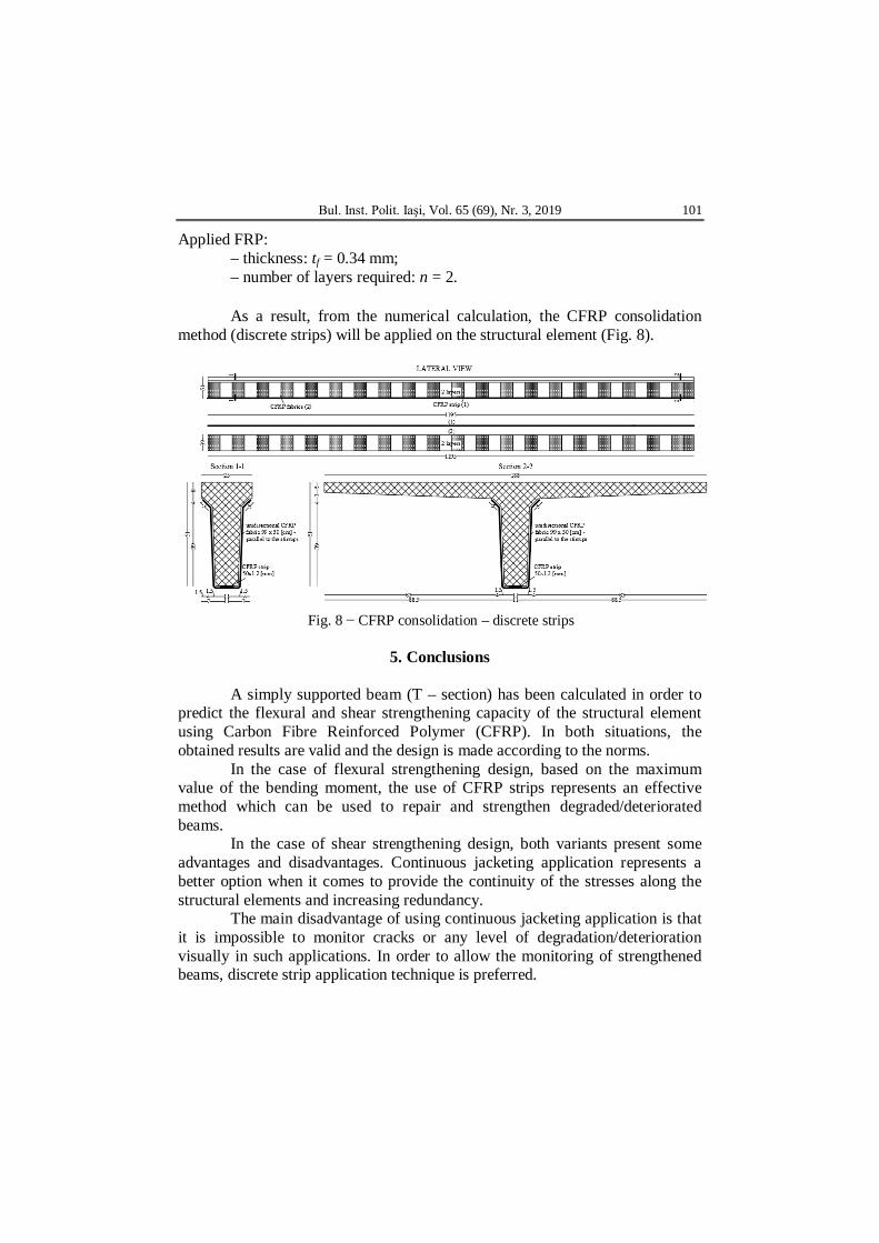
As a result, from the numerical calculation, the CFRP consolidation
method (discrete strips) will be applied on the structural element (Fig. 8).
Fig. 8 − CFRP consolidation – discrete strips
5. Conclusions
A simply supported beam (T – section) has been calculated in order to predict the flexural and shear strengthening capacity of the structural element using Carbon Fibre Reinforced Polymer (CFRP). In both situations, the obtained results are valid and the design is made according to the norms.
In the case of flexural strengthening design, based on the maximum value of the bending moment, the use of CFRP strips represents an effective method which can be used to repair and strengthen degraded/deteriorated beams.
In the case of shear strengthening design, both variants present some advantages and disadvantages. Continuous jacketing application represents a better option when it comes to provide the continuity of the stresses along the structural elements and increasing redundancy.
The main disadvantage of using continuous jacketing application is that it is impossible to monitor cracks or any level of degradation/deterioration visually in such applications. In order to allow the monitoring of strengthened beams, discrete strip application technique is preferred.
102 Alexandru Filip and Daniel Covatariu
Carbon Fibre Reinforced Polymer strips appear to be suitable solutions of increasing considerably the shear capacity of reinforced concrete beams. This increase depends strongly on more parameters such as: number of CFRP layers, concrete strength, orientation of fibre, shear span to depth ratio and size of the beam, amount of internal shear reinforcement.
REFERENCES
Atif M.A.H, Shear Behaviour of RC Beams Strengthened Externally with Bonded
CFRP-U Strips, Journal of Engineering Sciences, Assiut University, 35, 2, 361-379 (2007).
Karzad A.S., Al Toubat S., Maalej M., Estephane P., Repair of Reinforced Concrete Beams using Carbon Fibre Reinforced Polymer, MATEC Web of Conferences 120, 01008, 2017.
Kim Y., Quinn K., Satrom N., Garcia J., Sun W., Ghannoum W.M., Jirsa J.O., Shear Strengthening of Reinforced and Prestressed Concrete Beams Using Carbon Fibre Reinforced Polymer (CFRP) Sheets and Anchors, Center for Transportation Research, 2012.
Mofidi A., Chaallal O., Shear Strengthening of RC Beams with Externally Bonded FRP Composites: Effect of Strip-Width-to-Strip-Spacing Ratio, American Society of Civil Engineers, 2011.
Murali G., Pannirselvam N., Flexural Strengthening of Reinforced Concrete Beams using Fibre Reinforced Polymer Laminate: A Review, ARPN Journal of Engineering and Applied Sciences, 6, 11 (2011).
Soliman J., General Behaviour of T-section RC Beams Strengthened with Epoxy-Bonded Carbon Strands, MOJ Civil Engineering, 4, 213-217 (2018).
* * * Cod de proiectare. Bazele proiectării structurilor, CR 0-2012. * * * Sika® CarboDur® FRP Composites – Repararea şi consolidarea structu-rilor. OPTIMIZAREA CALCULULUI UNEI METODE DE CONSOLIDARE PENTRU O
GRINDĂ DIN BETON ARMAT UTILIZÂND COMPOZITE POLIMERICE ARMATE CU FIBRE DE CARBON
(Rezumat)
În ultimii ani, necesitatea de a reabilita/consolida fondul construit existent a
căpătat o importanţă deosebită din mai multe motive (extinderea perioadei de exploatare a construcţiilor, considerente economice etc.).
Această lucrare prezintă rezultatele unei investigaţii numerice a verificării la încovoiere şi forfecare a elementelor de acoperiş din beton armat ale unui rezervor de apă (grinzi de secţiune T) cu lamele şi împâslitură din fibre de carbon.
Evaluarea a fost realizată utilizând două programe software de calcul. În primă instanţă, datele de intrare au fost colectate pe baza unui program experimental.
Bul. Inst. Polit. Iaşi, Vol. 65 (69), Nr. 3, 2019 103
Evaluarea numerică a elementului structural din beton armat a fost realizată utilizând programul software SCIA Engineer, prin metoda elementului finit, pentru a determina valorile maxime ale eforturilor interne (momentul încovoietor, forţa tăietoare).
Ulterior, pe baza rezultatelor obţinute, proiectarea soluţiilor de consolidare utilizând CFRP a fost realizată cu ajutorul programului Sika® Carbodur® FRP Design.
Acest program permite verificarea la încovoiere (utilizând valoarea maximă a momentului încovoietor) pentru a determina dimensiunile lamelei CFRP şi verificarea grinzii la forfecare (utilizând valoarea maximă a forţei tăietoare) pentru a determina dimensiunile şi numărul de straturi de împâslitură.
În cazul consolidării la acţiunea forţei tăietoare, s-au calculat două tipuri de aplicare a CFRP pe elementul structural: cămăşuire continuă şi benzi discrete. Rezultatele obţinute pentru ambele variante prezintă unele avantaje şi dezavantaje. În ambele situaţii, rezultatele sunt valabile şi proiectarea se face conform normelor, concluzionând faptul că utilizarea CFRP (polimer armat cu fibră de carbon) reprezintă o metodă eficientă de consolidare care poate fi utilizată pentru a repara şi consolida grinzile degradate/deteriorate.