Embed Size (px)
Citation preview

General rights Copyright and moral rights for the publications made accessible in the public portal are retained by the authors and/or other copyright owners and it is a condition of accessing publications that users recognise and abide by the legal requirements associated with these rights.
• Users may download and print one copy of any publication from the public portal for the purpose of private study or research. • You may not further distribute the material or use it for any profit-making activity or commercial gain • You may freely distribute the URL identifying the publication in the public portal
If you believe that this document breaches copyright please contact us providing details, and we will remove access to the work immediately and investigate your claim.
Downloaded from orbit.dtu.dk on: Apr 07, 2018
Calculated shielding factors for selected European houses
Jensen, Per Hedemann
Publication date:1984
Document VersionPublisher's PDF, also known as Version of record
Link back to DTU Orbit
Citation (APA):Jensen, P. H. (1984). Calculated shielding factors for selected European houses. (Risø-M; No. 2474).
RISØ-M-2474
CALCULATED SHIELDING FACTORS FOR SELECTED EUROPEAN HOUSES
Per Hedemann Jensen
Abstract. Shielding factors for gamma radiation from activity
deposited on structures and ground surfaces have been calculated
with the computer model DEPSHIELD for single-family and multi
storey buildings in France, United Kingdom and Denmark. For
all three countries it was found that the shielding factors
for single-family houses are approximately a factor of 2 - 1 0
higher than those for buildings with five or more storeys.
Away from doors and windows the shielding factors for French,
British, and Danish single-family houses are in the range 0.03 -
0.1, 0.06 - 0.4, and 0.07 - 0.3, respectively. The uncertainties
of the calculations are discussed and DEPSHIELD-results are
compared with other methods as well as with experimental results.
INIS-describtors: APARTMENT BUILDINGS; COMPUTER CALCULATIONS;
DOSE RATES; EXTERNAL IRRADIATION; FALLOUT DEPOSITS; GAMMA RADIA
TION; RADIATION DOSES; SHIELDING; SURFACE CONTAMINATION; SUR
FACES; HOUSES
December 1984
Risø National Laboratory, DK 4000 Roskilde, Denmark

ISBN 87-550-1081-4
ISSN 0418-6435
Risø Repro 1984

CONTENT Page
1. INTRODUCTION 5
2. DEFINITIONS AND CALCULATING MODEL 6
2.1. Definition of the shielding factor 6
2.2. Outdoor shielding factor 6
2.3. Shielding factor for a residence 7
2.4. Weighted shielding factor 7
2.5. Time-averaged shielding factor 8
2.6. The calculating model DEPSHIELD 9
3. CALCULATION RESULTS 10
3.1. Calculated shielding factors for French houses .. 11
3.2. Shielding factors for British houses 12
3.2.1. Calculated shielding factors 12
3.2.2. Shielding factors calculated by the Home
Office 13
3.3. Calculated shielding factors for Danish Houses .. 14
4. DISCUSSION OF UNCERTAINTIES 18
5. SURVEY OF RELEVANT STUDIES 21
5.1. Calculations 21
5.2. Experiments 27
6. ACKNOWLEDGMENT 29


- 5 -
1. INTRODUCTION
In studies of the potential radiological consequences from hypo
thetical nuclear reactor accidents where radioactivity is re
leased to the atmospheref very little concern has so far been
given to the long-term radiation doses originating from activity
deposited on structures and ground surfaces.
In calculations of the T-radiation doses from deposited activity
the dose rate one meter above an infinite smooth, plane source is
normally used as a reference. The actual dose rate at a given
location is then found by multiplying this reference dose rate
with a modifying factor - the so-called shielding factor.
The shielding factor is usually defined as the ratio of the
indoor dose rate from deposited activity on an infinite ground
surface to the reference dose rate noted above.
More realistic dose calculations for urban areas need shielding
factors that also include radiation from deposited activity on
outer walls and roofs, and which consider the finite size of the
surrounding ground surface. Further, the shielding factor must
take into consideration the building construction regarding
building size, position of the apartment, window areas, and
thickness of walls, floors, and roofs.

- 6 _
2. DEFINITIONS AND CALCULATING MODEL
2.1. Definition of the shielding factor
The shielding factor is defined as
D S = —
Dref • •
where D is the actual dose rate and Dref a reference dose rate.
In this study the reference dot irate is chosen as the dose rate
1 meter above an infinite, smooth surface source having a uniform
activity concentration.
2.2. Outdoor shielding factor
A person staying out-of-doors in a contaminated urban area will
receive radiation doses from the contaminated roads as well as
from contaminated house walls. However, the buildings will act
both as radiation sources and as shields for radiation from
distant parts of the ground surface. The dose rate in urban
areas will therefore normally be less than that on an infinite
surface source with the same activity concentration. The out
door shielding factor SOU(- is given as:
• • • Dout,g + Dout,wl + Dout,w2
Sout = :
Dref
where Dout,g is the outdoor dose rate from activity deposited on
the ground and Dout,wl and DoutfW2 are the dose rates from the
activity deposited at the vertical walls at each side of the
road. The outdoor radiation at ground level from activity depo
sited on roofs is neglected, because a substantial part of it
will be absorbed in the building materials.

- 7 -
The outdoor shielding factor has been calculated to 0.5-0.8 for
urban areas. The shielding factor for cars and busses has been
measured to 0.3-0.7 (LAURIDSEN, B. et. al.).
2.3. Shielding factor for a residence
The radiation dose rate at an indoor residence in a multistorey
building or a single-family house will core from contaminated
roads, gardens, house walls, and roofs. Neighbouring houses will
act both as a shield for the radiation from distant parts of the
ground surface, and as a radiation source. In this study, the
radiation from neighbouring houses is neglected, as their contri
bution to the total indoor dose rate normally is insignificant.
The indoor shielding factor is given by:
. • • D i n , g + D in ,w + D i n , r
s . n = . Dref
where nj.n>q is the indoor dose rate from activity deposited on
the ground and Di n # w and Di n f r are the indoor dose rates from
activity deposited at the outer walls and roof, respectively.
2.4. Weighted shielding factor
For a given distribution of residences, a weighted shielding
factor is defined as:
sin ' I Pi * sin,i
where pi is the fraction of a given residence type (single family,
3rd storey in a 7-storey house, etc.) having the shielding factor
sin,i*
- 8 -
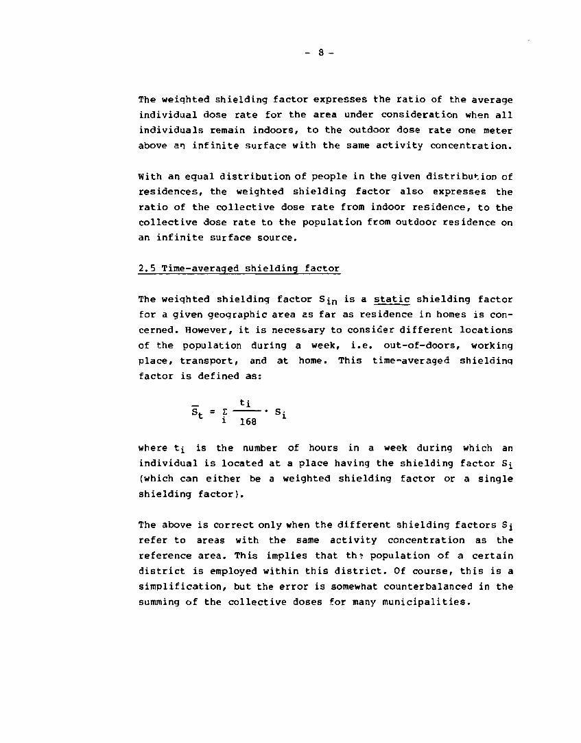
The weighted shielding factor expresses the ratio of the average
individual dose rate for the area under consideration when all
individuals remain indoors, to the outdoor dose rate one meter
above an infinite surface with the same activity concentration.
With an equal distribution of people in the given distribution of
residences, the weighted shielding factor also expresses the
ratio of the collective dose rate from indoor residence, to the
collective dose rate to the population from outdoor residence on
an infinite surface source.
2.5 Time-averaged shielding factor
The weighted shielding factor S^n is a static shielding factor
for a given geographic area as far as residence in homes is con
cerned. However, it is necessary to consider different locations
of the population during a week, i.e. out-of-doors, working
place, transport, and at home. This time-averaged shielding
factor is defined as:
ti
where t̂ is the number of hours in a week during which an
individual is located at a place having the shielding factor S^
(which can either be a weighted shielding factor or a single
shielding factor).
The above is correct only when the different shielding factors Sj
refer to areas with the same activity concentration as the
reference area. This implies that th? population of a certain
district is employed within this district. Of course, this is a
simplification, but the error is somewhat counterbalanced in the
summing of the collective doses for many municipalities.

- 9 -
Furthermore, it should be noted that both the weighted and the
time-averaged shielding factors should be used only to calculate
collective doses and average individual doses for the evaluation
of stochastic health effects, but not for calculating individual
doses for the assessment of non-stochastic health effects. For
this purpose, the area under consideration should be divided into
shielding classes and a time-averaged shielding factor calculated
for each.
2.6. The calculating model DEPSHIELD
The fundamental calculation method used here is based on the so-
called exponential point attenuation kernel that links the radia
tion flux density or another measurable quantity related to the
flux density at a given detector point to the point-source
strength. Attenuation resulting from geometrical spreading
with increasing distance from the source as well as exponential
attenuation and scattering of the photons are taken into consi
deration. The assumptions for the point-kernel method are that
both the source and shielding medium are isotropic, i.e. that
the source radiates uniformly in all directions, and that the
medium has the same attenuating properties in all directions.
Besides, as far as scattering of photons is concerned it is
assumed that both source and detector are located within an
infinite homogeneous medium. For a given extended isotropic
source the dose rate is found by proper integration of the
point kernel over the source extension.
The indoor dose rate from deposited activity on the different
surfaces can be calculated from the follwing general equation:
D i n = • J • E • I Q± I B(Iyt)- r z-exp(-2:pt) *dA 4 u \ p /air i A^
Eut is here the sum of all the mean free paths in the building
materials and air through which the photons will penetrate during
travel from source to detector point. Aj are the areas with the

- 10 -
activity concentration Qj. A computer code DEPSHIELD has been
developed to calculate the shielding factors from this general
equation (Hedemann Jensen, P. 1982).
3. CALCULATION RESULTS
The necessary input data for the calculation of shielding
factors are the mass-thickness for outer walls, roofs, floors,
inner walls, partition walls, and window fraction. Calculations
have been made for houses in Prance, Denmark and United Kingdom
based on informations from Ecole Polytechnique Feminine (DAVIN,
P. et. al. 1984), The Danish Building Research Institute and NRPB
(CRICK, M. et. al. 1984). Furthermore, results are given also for
different house types in the UK based on calculations from Home
Office Scientific Advisory Branch 1981. A more comprehensive
set of calculations for house types in all the CEC-countries
requires a detailed classification of the buildings in each
country as done in the Home Office report. The most important
parameters for such a classification are the mass-thickness of
outer walls, partition walls and floors. This is not done in
the present study, but some information can be extracted for
single-family and multistorey houses in most of the ten CEC-
countries.
For the single-family houses it is assumed in the calculations
that the dry deposition velocity to the surrounding ground area
is a factor of ten higher than to the house surfaces, resulting
in a ten-times higher activity concentration on the ground. For
multistorey buildings the deposition velocity to all surfaces
are assumed to be equal.
To give an impression of the importance of the different para
meters some parameter variations have been made in the calcu
lations of shielding factors for Danish houses.
-11 -
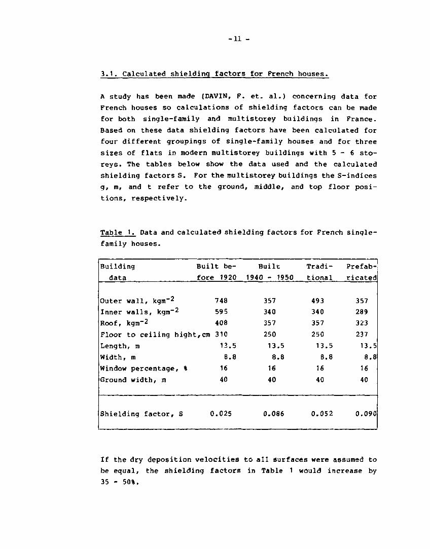
3.1. Calculated shielding factors for French houses.
A study has been made (DAVIN, F. et. al.) concerning data for
French houses so calculations of shielding factors can be made
for both single-family and multistorey buildings in France.
Based on these data shielding factors have been calculated for
four different groupings of single-family houses and for three
sizes of flats in modern multistorey buildings with 5 - 6 sto
reys. The tables below show the data used and the calculated
shielding factors S. For the multistorey buildings the S-indices
g, m, and t refer to the ground, middle, and top floor posi
tions, respectively.
Table 1. Data and calculated shielding factors for French single-
family houses.
Building
data
Outer wall, kgm"2
Inner walls, kgm"2
Roof, kgm"2
Built be
fore 1920
748
595
408
Floor to ceiling hight,cm 310
Length, m
Width, m
Window percentage, %
Ground width, m
Shielding factor, S
13.5
8.8
16
40
0.025
Built
1940 - 1950
357
340
357
250
13.5
8.8
16
40
0.086
Tradi
tional
493
340
357
250
13.5
8.8
16
40
0.052
Prefab
ricated
357
289
323
237
13.5
8.8
16
40
0.090
If the dry deposition velocities to all surfaces were assumed to
be equal, the shielding factors in Table 1 would increase by
35 - 50%.

- 12 -
Table 2. Data and calculated shielding factors for French modern
multistorey buildings
Building data
Outer wall, kgm~2
Inner walls, kgm"2
Partition walls, kgm~2
Floors, kgm-2
Roof, kgm-2
Floor to ceiling height, cm
Length, m
Width, m
Window percentage, %
Road width, m
Shielding factor, Sg
sm
st
Size of appartment
74 m2 88 m2 101 m2
418 418 418
272 272 272
374 374 374
418 418 418
418 418 418
250 250 250
10.38 12.18 13.98
8.58 8.58 8.58
16 16 16
40 40 40
0.041 0.035 0.030
0.010 0.0075 0.0055
0.017 0.015 0.014
3.2. Shielding factors for British houses
3.2.1. Calculated shielding factors
Within the CEC-MARIA project a set of benchmark problems has
been defined to compare three shielding models currently used
in UK, FRG, and Denmark. The building structures chosen for
this study was a typical British two-storey semi-detachted house
and a British eight-storey building. The table below shows the
data used and the calculated shielding factors by the DEPSHIELD-
code.

- 13 -
Table 3. Data and calculated shielding factors for British semi
detached and multistorey buildings.
Building data
Outer wall, kgm~2
Inner walls, kgm-2
Floors, kgm-2
Roof, kgrn-2
Floor to ceiling height, cm
Length, m
Width, m
Window percentage, %
Road and ground width, m
Shielding factor, Sg
Sm
st
Semi-detached Multistorey
320 690
230 - 396 230 - 396
22 690
68 460
300 320
16 20
14 20
10 13
30 - 100 >300
0.073 0.031
0.008
0.055 0.012
If the dry deposition velocity to all surfaces were assumed to
be equal for the semi-detached house, the shielding factor for
the bottom storey would be increased to 0.13 and for the upper
storey to 0.15.
3.2.2. Shielding factors calculated by the Home Office
Calculations of shielding factors have been made for 18 dif
ferent types of British dwellings (HOME OFFICE 1981). Activity
is assumed to be deposited equally on roof and ground, but not
on outer walls. The table below show the data and the calcu
lated shielding factors (central area).

-14 -
Table 4. Data and calculated shieldinq factors for the most
common British houses
Building data
Outer wall, kgm~2
Inner walls, kgm~2
Floors, kgm~2
Roof, kgm~2
Shielding factors:
One - storey, Sg
Two - storey, SQ
Si
Three - storey, So
Si
S2
}> Four storey, Sg
sm
! S t
Building type
Lightweight Modern Traditional
60 366 513-767
30 70-122 213-254
59 59 59
49-112 112 112
0.40 0.17 0.11
0.33 0.11-0.17 0.05-0.08
0.33 0.11-0.14 0.06-0.09
0.33 0.05 0.05-0.07
0.25 0.05 0.04-0.06
0.25 0.14 0.07-0.10
0.04
0.04
0.07
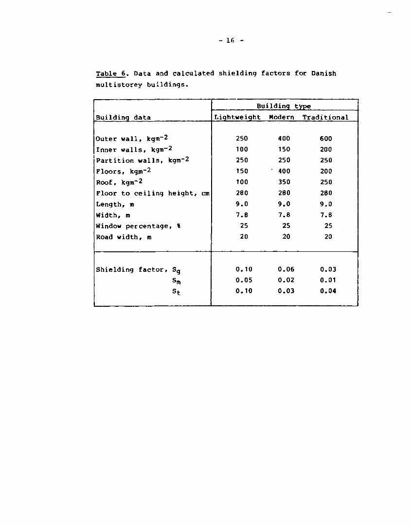
3.3. Calculated shieldinq factors for Danish houses
Based on building data from the Danish Building Research
Institute the Danish buildings are divided into three categories:
liqhtweiqht, modern, and traditional. The two tables below show
the data and calculated shieldinq factors for sinqle-family and
multistorey buildinqs.

- 15 -
Table 5. Data and calculated shielding factors for Danish single-
family houses
Building data
Outer wall, kqm-2
Inner walls, kgm-2
Roof, kgm-2
Floor to ceiling height, cm
Length, m
Width, m
Window percentage %
Ground width, m
Shielding factor, S
Buildinq type
Lightweight Modern Traditional
150 300 400
100 100 200
100 100 120
250 250 250
15 15 15
8 8 8
25 25 25
40 40 40
0.28 0.17 0.10
- 16 -
Table 6. Data and calculated shielding factors for Danish
multistorey buildings.
Building data
Outer wall, kgm~2
Inner walls, kgm~2
Partition walls, kgm~2
Floors, kgm~2
Roof, kgm"*2
Floor to ceiling height, cm
Length, m
Width, m
Window percentage, %
Road width, m
Shielding factor, Sg
Sm
st
Building type
Lightweight Modern Traditional
250 400 600
100 150 200
250 250 250
150 • 400 200
100 350 250
280 280 280
9.0 9.0 9.0
7.8 7.8 7.8
25 25 25
20 20 20
0.10 0.06 0.03
0.05 0.02 0.01
0.10 0.03 0.04

- 17 -
To give an impression of the importance of the building
parameters, a variation of outer wall and inner wall thickness,
ground width, and window percentage have been made. The results
are shown in Table 7. The parameter variations are shown in the
left column. The value below the variation interval is the
fixed value of the considered parameter when the others are
varied.
Table 7. Shielding factor variation for Danish houses.
Parameter
variation
Outer wall, kgm~2
255 • 595
s:410 m:595
Inner wall, kgm"^
0 + 425
220
Ground width, m
20 * -
s:15 m:20
Window percentage,
10*50
25
Building type
Single-
family
S
.15*.043
.10*.056
.075*.13
%
.051*.095
Multistorey
Sg Sm St
.089*.032 .032*.011 .051*.033
.051*.027 .018*.009 .058+.030
.032*.051 .011*.021 .033*.041
.018+.06 .006*.021 .029+.042

- 18 -
4. DISCUSSION OF UNCERTAINTIES
The fundamental calculation method used in this study is based
on the so-called exponential point attenuation kernel that links
the radiation flux density or other measurable quantities related
to the flux density at a given detector point to the point-source
strength. Attenuation resulting from geometrical spreading
with increasing distance from the source as well as exponential
attenuation and scattering of the photons are taken into con
sideration. The assumptions for the point-kernel method are that
both the source and shielding medium are isotropic, i.e. that
the source radiates uniformly in all directions and that the
medium has the same attenuating properties in all directions.
Besides, as far as scattering of photons is concerned, it is
assumed that both source and detector are located within an
infinite homogeneous medium.
These assumptions are approximately fulfilled in the calcu
lations of the reference dose rate and the outdoor dose rate
from finite surfaces as verified by transport theory calcu
lations and experimental measurements (LAURIDSEN, B. et al.).
Therefore, the outdoor dose rate can be calculated with an
accuracy of perhaps 10-20%.
Otherwise, in the calculation of the indoor dose rate the as
sumption that the source and the detector should be located
within an infinite medium is not fulfilled. As the dose build
up factors have been derived for an infinite medium, the indoor
dose rate is overestimated in some cases when calculated from
the point-kernel method. The infinity assumption is nearly
always fulfilled for the building walls for photons penetrating
the wall perpendicular or nearly perpendicular from source to
detector point. All the primary photons that is scattered in the
wall will arise here from a wall area within 2-3 mean free
paths in the yall material around the primary photon direction,
i.e. within a 10-40 cm radius, depending on the photon energy.

- 19 -
On the other hand, as the detector point inside an apartment
is surrounded by air, the infinity assumption can never be
fulfilled along the photon direction. Therefore, the photons
that will be back-scattered in an homogenous medium from the
semi-infinite medium behind the detector point will be absent.
However, it is believed that this is somewhat counterbalanced
by the back-scatter from inner walls, floor, and ceiling in the
apartment. The back-scatter component that is contained in the
dose build-up factor is of importance only for lower photon
energies and can be neglected for energies above 1 MeV (JAEGER,
R.G. et al.).
The skyshine component from photon scattering in air is in
directly included in the model, as the build-up factor is
calculated from the sum of all the mean free paths in building
structures and an infinite air slab with a thickness 3.,ual to the
distance between the detector point and each infinitesimal area
source.
As far as basements are concerned the main radiation contribution
here may come from radiation scattering in the walls of the
ground storey and penetrating downwards (SMOKE, M.A.). This
"in-and-down" effect cannot be handled by the DEPSHIELD model,
and shielding factors for basements cannot be calculated from
the present model.
A similar problem exists for the detector points at the upper
stories in high buildings. Here the main component may be the
primary and air-scattered photons having penetrated air only
and reaching the outer wall right outside the detector storey.
The photons may then be scattered in the wall and emerge from
the inner side of the wall to reach the detector point. There
fore, the ground radiation component at upper stories could be
seriously underestimated.

- 20 -
Another important source of uncertainty is the deposition velo
cities for the different surfaces such as roads, gardens,
walls, and roofs. In this study it is assumed that the depo
sition velocities to all surfaces apart from gardens are equal,
and for gardens a factor of ten higher (ROED, J.).
If, for instance, the deposition velocity to roofs and walls
is equal to that of the garden, then the shielding factor for a
normal single-family house would be doubled. Additionally, if
the deposition velocity to outer walls is neglected, as is done
in several studies (SPENCER, L.V. et al., DEFENCE CIVIL PREPARAD-
NESS AGENCY, HOME OFFICE SCIENTIFIC ADVISORY BRANCH, BURZON,
Z.G. et. al., STRICKLER, T. et al.), then the shielding factor
for the middle floors in multistorey buildings would decrease
by as much as a factor of 30. Therefore, when calculating
realistic shielding factors it is very important that the ratio
of the deposition velocity at one surface to another is known.
Uncertainties will also depend on geometrical simplifications
of the buildings and their surroundings and the data used in
the calculations for attenuation, build-up, and energy absorp
tion. However, it is believed that these uncertainties are
less important compared with those already mentioned.
It is concluded that shielding factors for simple one- and two-
storey structures can be calculated fairly accurately. The
same will be the case in the lower-placed residences of a multi
storey compartmented building. In the upper residences of
multistorey buildings with heavy outer walls the radiation from
ground deposits may be dominated by photons scattered by the
wall just outside the detector storey. This scatter component
ceinnot be calculated by the point-kernel method, and therefore
the ground radiation dose rate at the upper storeys may be
underestimated in some cases. However, the deposited activity
on roof and outer walls may be the dominant sources at these
residences. This will therefore tend to make the underestimate
of the ground dose rate insignificant.
- 21 -
5. SURVEY OF RELEVANT STUDIES
Attempts to develop satisfactory methods for estimating shield
ing factors for ordinary buildings against gamma radiation from
radioactive fallout began in the early 1950's. Intensive re
search of many kinds was carried out in the decade from the mid-
fifties to the mid-sixties. In the period following there has
been a steady decline in new research on these problems. The
sections below survey studies on shielding factor estimates
based on experiments or calculations.
5.1. Calculations
One of the earliest calculating procedures is the "DCPA Standard
Method for Fallout Gamma Radiation Shielding Analysis" (DEFENCE
CIVIL PREPAREDNESS AGENCY) that is based on the basic data and
primary calculations made by SPENCER (1962). The Standard
Method includes the radiation contribution from activity de
posited on the roof and the surrounding ground area, but not
the contribution from activity deposited on outer wall surfaces.
Much experimental effort has gone into verifying the shielding
factors calculated by the Standard Method, and the method is
still widely used today for civil defence applications.
The Standard Method calculates the ground radiation contribu
tion to the shielding factor as the product of a geometry fac
tor, an exterior wall barrier factor, an interior wall attenua
tion factor, and floor and ceiling attenuation factors. The to
tal ground geometry factor includes geometrical factors for
direct radiation throuqh that portion of a wall lying below the
detector plane, for skyshine radiation through that portion of
a wall lying above the detector plane and for scatter radiation
through the walls lying above and below the detector plane. The
primary overhead radiation contribution to the shielding factor
depends on the solid angle fraction subtending the roof source
and the mass-thickness of the roof. Modifying attenuation fac
tors for the presence of inner walls, ceilings and floors are
- 22 -
multiplied to the primary overhead contribution. The presence of
wall apertures, such as windows and doors affects the qround
radiation contribution both as direct radiation and ceilinq-shine
radiation. The effect of an aperture is generally to increase
the contribution and to decrease the protection, particularly
if apertures exist below the detector Diane, so that direct
radiation may reach the detector point without passing any bar
riers. The Standard Method determines the direct aperture and
ceiling-shine radiation components by modifying the total ground
geometry factor and by adding a ceiling-shine geometrical factor.
A detailed desciption of the Standard Method is given in
(SPENCER, L.V. et al.r DEFENCE CIVIL PREPAREDNESS AGENCY).
Two computer codes CAPS-2 (DURST, J.L.) and PF-COMP (LYDAY,
R.O. et al.), which have the Standard Method as basis, were
produced for use by the US Office of Civil Defense. These two
computer programs perform the numerical equivalent of the
reading of charts and graphs in the manual TR-20 (DEFENCE CIVIL
PREPAREDNESS AGENCY) and do the many calculation sequences that
would be involved in a hand calculation. A comparison between
these two codes has been made (GRITZNER, M.L. et al.), and it
is concluded that the PP-COMP code is better than CAPS-2; the
latter should be restricted to calculating structures with low
protection factors (about 20 or less) and/or of only limited
complexity.
A three-dimensional Monte Carlo code TERP (COHEN, M.O.) has
been developed to treat complex structures and non-uniform
terrain. Calculational results obtained using the TERF code are
in generally good agreement with the experimental results ob
tained at Kansas State University for a blockhouse erected for
the experiments (SPENCER, L.V. et al.). Also calculations of
the dose rate in the basement of a typical shielding structure
both with and without basement ceiling are in generally good
agreement with the results obtained from the Standard Method
using the empirical revised ceiling attenuation factor given by
Eisenhauer (SPENCER, L.V. et al.). Other important conclusions
-23 -
have been reached from studies with TERF. It has been shown,
for a particular geometry, that the dose rate in the building
is completely insensitive to the slope of the surrounding
ground surface source, for slopes less than 15 degrees. Besides,
the "half-height flat roof" approximation that also is used in
the DEPSHIELD code should be used with some reservation.
Another Monte Carlo code, COHORT (FRENCH, R.L. et al.) was used
to calculate shieldinq factors for an upright cylindrical
concrete barrier with a 10-ft radius exposed to gamma rays from
infinite and finite-plane 60Co sources. Comparisons with shield
ing factors calculated by the Standard Method showed that
the two methods agreed within 10 pet. for the infinite-plane
source. For the finite sources the COHORT factors were from 45
pet. higher to 30 pet. lower than corresponding Standard Method
factors for small and large solid angle fractions, respectively.
One of the conclusions from this study is that the importance of
wall scatter radiation increases sharply with increased wall
thickness; it is 24 pet. of the indoor dose for a mass-thickness
of 98 kg «r2, 39 pet. for 195 kg m-2, and 55 pet. for 390
kg m~2. Corresponding percentages for wall scattering computed
with the Standard Method are higher by 95, 65, and 55 pet.,
respectively. The Monte Carlo data indicated that separate
directional response functions should be used for radiation
coming from above and from below the detector plane. It was
concluded that any errors in the Standard Method data and as
sumptions must tend to compensate one another, and that similar
Monte Carlo studies must be made of other aspects of the Standard
Method in order to fully understand these implications.
In (CLARKE, E.T. et al.) and (BURSON, Z.G. et al.) calculated
shielding factors from the Standard Method are shown for simple
and more complex structures. For 10 x 10 meter simple block
hmses the shielding factor for fallout activity on roof and
ground surfaces is of the magnitude 0.06 - 0.15 for wall mass-
thicknesses in the range 300-500 kg m"2.

- 24 -
In the manual TR-20 (DEFENCE CIVIL PREPAREDNESS AGENCY) several
illustrative problems are presented to emphasize the methods
used to calculate shielding factors from the Standard Method.
Pour of these problems have been calculated by DEPSHIELD to
make a comparison with the Standard Method. Case 1 (Problem 4-4
in TR-20) is a simple one-storey blockhouse without windows,
placed on an infinite ground surface. Case 2 (Problem 4-19) is
also a simple windowless one-storey blockhouse placed on a
surface with finite dimensions. The ground area is quadratic
with a size of 1176 n>2. Case 3 (Problem 4-15) is a simple
one-storey blockhouse with windows, placed on an infinite
ground surface. The window areas cover approximately 55% of the
outer wall area of the building. Finally, case 4 (Problem
4-13) is a multistorey building with interior walls, placed on
an infinite ground surface. The detector point is placed at the
ninth storey.
The following table shows the shielding factors for the four
cases calculated by DEPSHIELD for 1 MeV photons and by the
Standard Method. It is assumed that no activity has been
deposited on the outer wall surfaces.
Table 8. Shielding factors calculated by the Standard Method
and the OEPSHIELD-code for selected problems in the
Manual TR-20.
Case No.
1
2
3
4
Shielding Pactor
Standard Method
0.061
0.035
0.21
0.0075
DEPSHIELD
0.069
0.031
0.26
0.0050
- 25 -
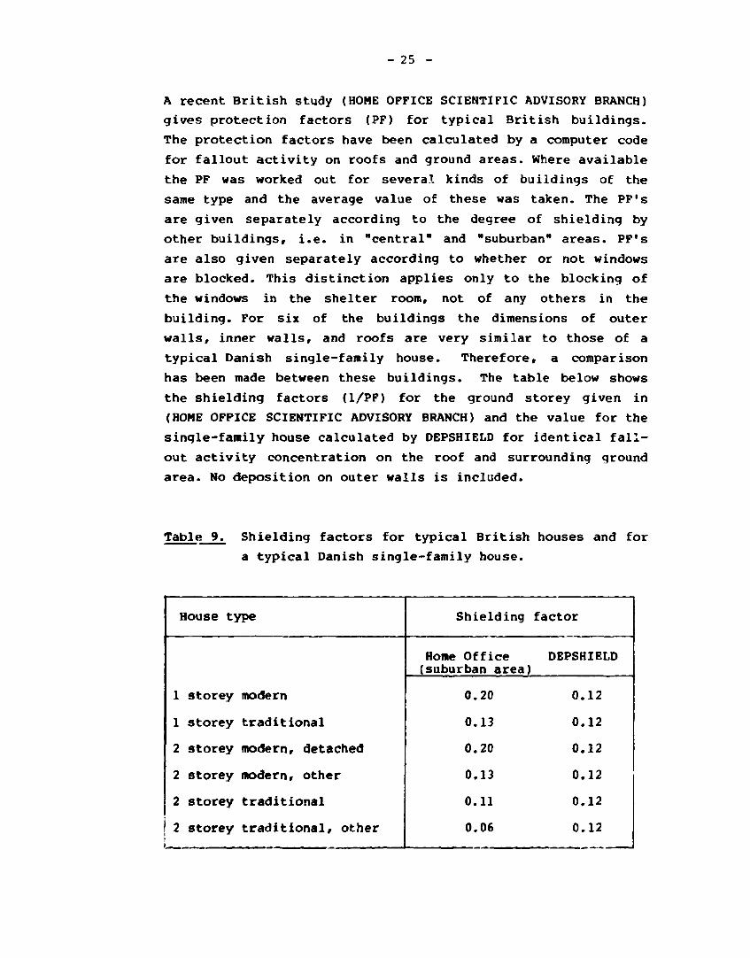
A recent British study (HOME OFFICE SCIENTIFIC ADVISORY BRANCH)
gives protection factors (PF) for typical British buildings.
The protection factors have been calculated by a computer code
for fallout activity on roofs and ground areas. Where available
the PF was worked out for several kinds of buildings of the
same type and the average value of these was taken. The PF's
are given separately according to the degree of shielding by
other buildings, i.e. in "central" and "suburban" areas. PF's
are also given separately according to whether or not windows
are blocked. This distinction applies only to the blocking of
the windows in the shelter room, not of any others in the
building. For six of the buildings the dimensions of outer
walls, inner walls, and roofs are very similar to those of a
typical Danish single-family house. Therefore, a comparison
has been made between these buildings. The table below shows
the shielding factors (1/PF) for the ground storey given in
(HOME OFFICE SCIENTIFIC ADVISORY BRANCH) and the value for the
single-family house calculated by DEPSHIELD for identical fall
out activity concentration on the roof and surrounding ground
area. No deposition on outer walls is included.
Table 9. Shielding factors for typical British houses and for
a typical Danish single-family house.
House type
1 storey modern
1 storey traditional
2 storey modern, detached
2 storey modern, other
2 storey traditional
2 storey traditional, other
Shielding factor
Home Office DEPSHIELD (suburban area)
0.20 0.12
0.13 0.12
0.20 0.12
0.13 0.12
0.11 0.12
0.06 0.12
- 26 -
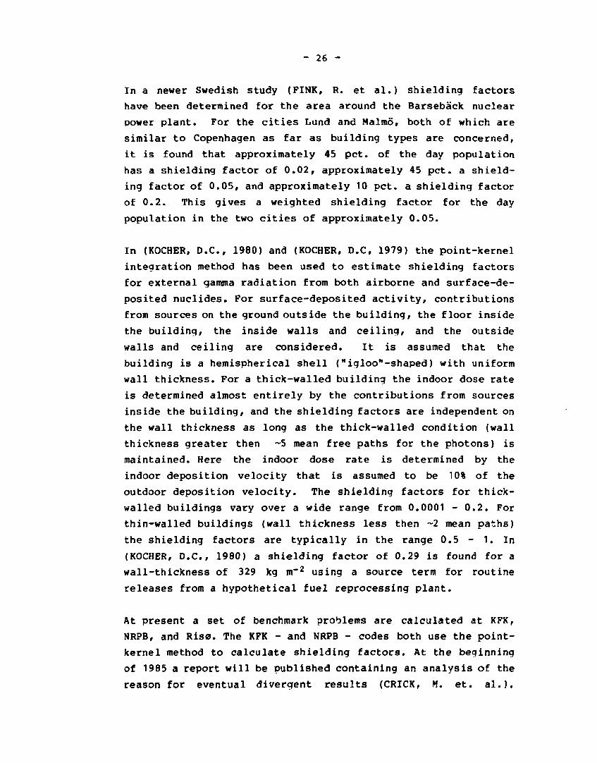
In a newer Swedish study (FINK, R. et al.) shielding factors
have been determined for the area around the Barsebåck nuclear
power plant. For the cities Lund and Malmo, both of which are
similar to Copenhagen as far as building types are concerned,
it is found that approximately 45 pet. of the day population
has a shielding factor of 0.02, approximately 45 pet. a shield
ing factor of 0.05, and approximately 10 pet. a shielding factor
of 0.2. This gives a weighted shielding factor for the day
population in the two cities of approximately 0.05.
In (KOCHER, D.C., 1980) and (KOCHER, D.C, 1979) the point-kernel
integration method has been used to estimate shielding factors
for external gamma radiation from both airborne and surface-de
posited nuclides. For surface-deposited activity, contributions
from sources on the ground outside the building, the floor inside
the building, the inside walls and ceiling, and the outside
walls and ceiling are considered. It is assumed that the
building is a hemispherical shell ("igloo"-shaped) with uniform
wall thickness. For a thick-walled building the indoor dose rate
is determined almost entirely by the contributions from sources
inside the building, and the shielding factors are independent on
the wall thickness as long as the thick-walled condition (wall
thickness greater then ~5 mean free paths for the photons) is
maintained. Here the indoor dose rate is determined by the
indoor deposition velocity that is assumed to be 10% of the
outdoor deposition velocity. The shielding factors for thick-
walled buildings vary over a wide range from 0.0001 - 0.2. For
thin-walled buildings (wall thickness less then ~2 mean paths)
the shielding factors are typically in the range 0.5 - 1. In
(KOCHER, D.C., 1980) a shielding factor of 0.29 is found for a
wall-thickness of 329 kg m~2 using a source term for routine
releases from a hypothetical fuel reprocessing plant.
At present a set of benchmark problems are calculated at KFK,
NRPB, and Risø. The KFK - and NRPB - codes both use the point-
kernel method to calculate shielding factors. At the beginning
of 1985 a report will be published containing an analysis of the
reason for eventual divergent results (CRICK, M. et. al.).

- 27 -
5.2. Experiments
In the late 1950's and early 1960*s a series of shielding expe
riments with simple blockhouses and complex structures were made
in the U.S. (REXROAD, R.E. et al., AUXIER, J.A. et al., BURSON,
Z.G. 1966, BURSON, Z.G. 1970, STRICKLER, T. et al., BORELLA, H.
et al., BATTER, J. et al., ROBINSON, H.J. et al.). The fall
out source on the roof was normally simulated by a grid of
point sources and the plane ground source by pumping a source
through a length of tubing placed around the house. The system
consisted of a remotely controlled hydraulic pumping unit which
pumped the radioactive source through the tubing. High inten
sity sources of the nuclides 6nCo and 137cs were used. The cal
culations by the Standard Method and the experiments agree in
most cases to better than 20% for both the simple block houses
and complex structures over a range of shielding factors down
to • 0.01. Experiments on multistorey buildings with interior
walls showed that the measured shielding factor was practically
insensitive to the placement of the interior walls either close
to the detector point in the middle of the house or close to
the outer wall. This confirms the validity of the method used
in DEPSHIELD, where the interior wall thickness is added to the
outer wall thickness.
DEPSHIELD has been used to calculate the shieldinq factors mea
sured in one of the Kansas State University experiments (SPENCER,
L.V. et al.). One of the structures erected for the experi
mental programme was a concrete blockhouse 20 ft x 20 ft with a
first-storey height of 8 ft and a basement height of 8 ft. The
walls had a mass-thickness of 34 g»cm~2 and the roof and base
ment ceiling a thickness of 27 g»cm~2. The blockhouse contained
a door and a window. A plane source on the roof of the blockhouse
was simulated by 4.6 mCi point sources of 60co placed at two-
foot intervals. A plane source on the ground around the block
house was simulated by a tube source laid out in three areas
covering a quarter-circular area of 160 ft radius from the
center of the block house. The estimated contribution from the

- 28 -
ground source beyond 160 ft accounted for 20-40% of the total
exposure on the first (ground) storey. The instrumentation
included 20R and 200 mR pocket dosimeters, Landsverk 2R dosi
meters, and Victoreen 1R and 10 mR ion chambers. The measured
shielding factors on the vertical centerline of the first
storey aqreed with calculations by the Standard Method within a
few percent.
The table below shows the measured shielding factors and the
calculated shielding factors for the ground storey by the code
DEPSHIELD, without deposition on the outer walls.
Table 10. Measured and calculated shielding factors for the
Kansas State University blockhouse.
Source
Ground contribution
Roof contribution
Experiment
0.18-0.25
0.05
- — — — - - " • - • i - •
DEPSHIELD
0.22
0.051
Other experiments with one- and two-storey houses (BURSON, Z.G.
1366) gave shielding factors of C.l-0.2 measured in outer rooms
and 0.05-0.1 measured in inner rooms. These figures agree
reasonable well with the calculated shielding factors for
Danish one- and two-storey houses of the range 0.04-0.28,
where the contribution from deposited activity on outer walls is
included.

- 29 -
6. ACKNOWLEDGMENT
The present work was part of the CEC Radiation Protection Pro
gramme and performed under a subcontract with Association
Euratom - C.E.A. No. SC-014-BIAP-423-DK(SD).
- 30 -
7. REFERENCES
AUXIER, J.A., BUCHANAN, J.O., EISENHAUER, C. and MENKER, H. E.r
1959, "Experimental Evaluation of the Radiation Protection
Afforded by Residential Structures Against Distributed Sour
ces", Report CEX-58.1, 133 pages (Civil Effects Test Opera
tions, U.S.A.E.C.).
BATTER, J., KAPLAN, A. and CLARKE, E., 1960, "An Experi
mental Evaluation of the Radiation Protection Afforded by a
Large Modern Concrete Office Building", CEX-59.1, 69 pages
(Civil Effects Test Operations, U.S.A.E.C).
BORELLA, H., BURSON, Z. and JACOVITCH, J., 1961, "Evalua
tion of the Fallout Protection Afforded by Brookhaven Natio
nal Laboratory Medical Research Center", CEX-60.1, U.S.
Atomic Energy Commission.
BURSON, Z., 1963, "Experimental Evaluation of the Fallout-
Radiation Protection Provided by Selected Structures in
the Los Angeles Area", CEX-61.4, 106 pages (Civil Effects
Test Operations, U.S.A.E.C.).
BURSON, Z.G., "Experimental Radiation Measurements in Con
ventional Structures", CEX-59.7B, U.S. Atomic Energy Commis
sion, Part I, July 1966, Part II, February 1963; Part III,
November 1965.
BURSON, Z.G., 1970, "Experimental Evaluation of the Fallout-
Radiation Protection Provided by Structures in the Control
Po t Area of the Nevada Test Site", CEX-69.5, U.S. Atomic
Energy Commission.
BURSON, Z.G. and PROFIO, A.E., 1975, "Structure Shieldinq
from Cloud and Fallout Gamma-Ray Sources for Assessinq
the Consequences of Reactor Accidents". EGG-1183-1670. Las
Vegas, Nevada.

- 31 -
CRICK, M., GRAF, 0. and HEDEMANN JENSEN, P. (1985). A comparison
between three computer codes in use within the CEC to calculate
shieldinq factors of buildings fro« deposited radioactivity.
Report on benchmark calculations in the CEC-MARIA project.
NRPB/KfK/RIS0 (In preparation).
CLARKE, E.T. and Buchanan, J.O., 1962, "Radiation Shielding
Against Fallout", Nucleonics 20, No. 8, 143.
COHEN, M.O., 1970, "TERF Monte Carlo Fallout Code Calculations",
Office of Civil Defense MR-7002.
OAVIN, P., MAUVIGNER,V., PORTE, E. and VERGNBS, B. (1984). Etude
de 1'importance de 1'urbanisation et des caracLeristiques
regionales des habitations, en vue des calculs de protection.
Ecole Polytechnique Feminine - Projet. Contract SC-017-F/BIA
P 423-P(AD).
DEFENSE CIVIL PREPAREDNESS AGENCY, 1976, "Shelter Design And
Analysis", TR-20 (Vol. 1), Washington D.C.
DURST, J.L. 1966, "CAPS-2, A Computerized Method of Analyzing
Structures for Radiation Shielding", Tech. Serv. Directorate,
Off of Civ. Def., USA.
PINK, R.r et.al., 1980, "Consequences and Measures by Large
Releases of Radionuclides from Swedish Nuclear Power Plants
during Emergency and War", FOA, A 40032-A1, Sweden (In Swe
dish).
FRENCH, R.L., PRICE, J.H. and OLMEDO, L., 1967, "Monte Carlo
Study of Structure Shielding Against Pallout Radiation". RRA-
T73, Radiation Research Associates.
GRITZ'JER, M.L. and STEVENS, P.N., 1968, "A Comparison of the
Building Protection Factor Codes CAPS-2 and PF-COMP". Oak
Ridge National Laboratory Report No. ORNL-TM-2285.
- 32 -
HEDEMANN JENSEN, P., 1982, "Shielding factors for Gawaa Radiation
from Activity Deposited on Structures and Ground Surfaces",
Rise-M-2270.
HOME OFFICE SCIENTIFIC ADVISORY BRANCH, 1981, "Protective Quali
ties of Buildings", Hone Office, London.
JAEGER, R.G., et.al., 1968, "Engineering Compendium on Radiation
Shielding: Shielding Fundamentals and Methods", Vol. I pp.
225-226, Springer Verlag, Berlin-Heidelberg-New York.
KOCHER, D.C., 1979, "Effects of Man's Residence Inside Building
Structures on Radiation Doses from Routine Releases of
Radionuclides to the Atmosphere", ORNL/TM-6526, Oak Ridge
National Laboratory.
KOCHER, D.C., 1980, "Effects of Indoor Residence on Radiation
Doses from Routine Releases of Radionuclides to the Atmos
phere", Nucl. Tech., Vol. 48, 171-179.
LAURIDSEN, B. and HEDEMANN JENSEN, P., 1982, "Shielding Factors
for Vehicles to Gamma Radiation from Activity Deposited on
Structures and Ground Surfaces", Risø-M-2339.
LYDAY, R.O., WRIGHT, M. D. and HILL, E.L., 1968, "PF-COMP Com
puter Program for Fallout Protection Factor Analysis of
Buildings", Part I and II, Res. Tri. Inst., USA.
REXROAD, R.E., SCHMOKE, M.A., TILLER, H.J., FODERARO, A.,
DEGELMANN, L and KOWAL, G., 1964, "Point-to-point Kernel
Analysis of an Experiment to Determine Wall Penetration
of a Square-based Concrete Structure by Gamma Radiation",
Nucl. Sci. and Eng. 20, No. 1, 66-79
ROBINSON, M. J., et.al., 1969, "A University Design Study of
Protection Factors in Typical American Houses", KSU Report
84, Kansas State University.

- 33 -
ROED, J., 1983, "Deposition Velocity of Caesium-137 on Vertical
Buildinq Surfaces", Atmospheric Environment Vol. 17, pp
663-664.
SMOKE, M.A., 1973, "In-and-Down Scattered Radiation in a Simple
Concrete Structure", Ballistic Research Laboratory Report
No. 1665, 161 pages.
SPENCER, L.V., 1962, "Structure Shielding Against Fallout Radia
tion From Nuclear Weapons", NBS Monograph 42.
SPENCER, L.V., CHILTON, A.B. and EISENHAUER, CM., 1980, "Struc
ture Shielding Against Fallout Gamma Rays from Nuclear
Detonations", NBS Special Publication 570, U.S. Department
of Commerce/National Bureau of Standards, Washington, D.C.
STRICKLER, T. and AUXIER, J., 1960, "Experimental Evaluation
of the Radiation Protection Afforded by Typical Oak Ridge
Homes Against Distributed Sources", CEX-59.13, 51 pages
(Civil Effects Test Operations, U.S.A.E.C.).
TVETEN, U., 1982, "Shielding Factors for Typical Houses in the
Nordic Countries", IFE-KR-E-82-001-V, Institute for Energy
Technology, Kjeller, Norway.

Risø National Laboratory iUsø-M-[ilLL]
T f
Oft
Title and author(s)
Calculated Shielding Factors for Selected
European Houses
Per Hedemann Jensen
Group's own reg i s t ra t ion number(s)
33 pages + 10 tables + i l l u s t r a t i ons
D a t e December 1984
Department or group
Health Physics
Abstract
Shielding factors for gamma radiation from ac
tivity deposited on structures and ground sur
faces have been calculated with the computer
model DEPSHIELD for single-family and multi
storey buildings in France, United Kingdom and
Denmark. For all three countries it was found
that the shielding factors for single-family
houses are approximately a factor of 2 - 10
higher than those for buildings with five or
more storeys. Away from doors and windows the
shielding factors for French, British, and Dan
ish single-family houses are in the range 0.03
-0.1, 0.06-0.4, and 0.07-0.3, respectively. The
uncertainties of th-: calculations are discussed
and DEPSHIELD-results are compared with other
methods as well as with experimental results.
Copies to
Available on request from Ris* Library, Risø National Laboratory (Ris«J Bibliotek), Forsøgsanlæg Risø), DK-4000 Roskilde, Denmark Telephone: (03) 37 12 12, ext. 2262. Telex: 43116