Embed Size (px)
Citation preview
rev2.03
AMDCompute Abstraction Layer (CAL)
Programming
D e c e m b e r 2 0 1 0
ii
© 2010 Advanced Micro Devices, Inc. All rights reserved. AMD, the AMD Arrow logo, ATI, the ATI logo, Radeon, FireStream, FireGL, Catalyst, and combinations thereof are trademarks of Advanced Micro Devices, Inc. Microsoft, Windows, and Windows Vista are registered trademarks of Microsoft Corporation in the U.S. and/or other jurisdictions. OpenCL and the OpenCL logo are trademarks of Apple Inc. used by permission by Khro-nos. Other names are for informational purposes only and may be trademarks of their re-spective owners.
The contents of this document are provided in connection with Advanced Micro Devices, Inc. (“AMD”) products. AMD makes no representations or warranties with respect to the accuracy or completeness of the contents of this publication and reserves the right to make changes to specifications and product descriptions at any time without notice. The information contained herein may be of a preliminary or advance nature and is subject to change without notice. No license, whether express, implied, arising by estoppel or other-wise, to any intellectual property rights is granted by this publication. Except as set forth in AMD’s Standard Terms and Conditions of Sale, AMD assumes no liability whatsoever, and disclaims any express or implied warranty, relating to its products including, but not limited to, the implied warranty of merchantability, fitness for a particular purpose, or infringement of any intellectual property right.
AMD’s products are not designed, intended, authorized or warranted for use as compo-nents in systems intended for surgical implant into the body, or in other applications intended to support or sustain life, or in any other application in which the failure of AMD’s product could create a situation where personal injury, death, or severe property or envi-ronmental damage may occur. AMD reserves the right to discontinue or make changes to its products at any time without notice.
Advanced Micro Devices, Inc.One AMD PlaceP.O. Box 3453
Sunnyvale, CA 94088-3453www.amd.com
A M D A C C E L E R A T E D P A R A L L E L P R O C E S S I N G
Preface iiiCopyright © 2010 Advanced Micro Devices, Inc. All rights reserved.
Preface
About This DocumentThis document describes the AMD Compute Abstraction Layer (CAL). It provides a specification of the CAL interface, as well as descriptions of its architecture and programming model.
AudienceThis document is intended for programmers. It assumes prior experience in writing code for CPUs and basic understanding of threads. While a basic understanding of GPU architectures is useful, this document does not assume prior graphics knowledge.
OrganizationThis document begins with an overview of the AMD Compute Abstraction Layer (CAL), including the system architecture and programming model. Chapter 2 provides a description of the CAL runtime, the CAL compiler, and kernel execution. Chapter 3 walks through a simple HelloCAL application. Chapter 4 provides information on fine-tuning CAL code for performance. Chapter 5 uses a common Linear Algebra problem to show how to develop CAL stream kernels. Chapter 6 discusses the AMD CAL/Direct3D interoperability. Chapter 7 discusses advanced topics for developers who want to add new features to CAL applications or use specific features in certain AMD processors. Appendix A is the specification for the CAL platform. Appendix B is the CAL binary format specification (CALimage). The last section of this book is a glossary of acronyms and terms.
A M D A C C E L E R A T E D P A R A L L E L P R O C E S S I N G
iv PrefaceCopyright © 2010 Advanced Micro Devices, Inc. All rights reserved.
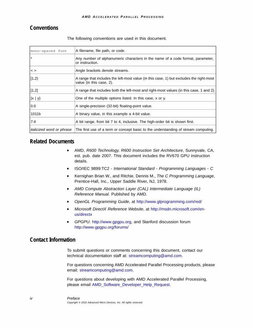
ConventionsThe following conventions are used in this document.
Related Documents• AMD, R600 Technology, R600 Instruction Set Architecture, Sunnyvale, CA,
est. pub. date 2007. This document includes the RV670 GPU instruction details.
• ISO/IEC 9899:TC2 - International Standard - Programming Languages - C
• Kernighan Brian W., and Ritchie, Dennis M., The C Programming Language, Prentice-Hall, Inc., Upper Saddle River, NJ, 1978.
• AMD Compute Abstraction Layer (CAL) Intermediate Language (IL) Reference Manual. Published by AMD.
• OpenGL Programming Guide, at http://www.glprogramming.com/red/
• Microsoft DirectX Reference Website, at http://msdn.microsoft.com/en-us/directx
• GPGPU: http://www.gpgpu.org, and Stanford discussion forumhttp://www.gpgpu.org/forums/
Contact InformationTo submit questions or comments concerning this document, contact our technical documentation staff at: [email protected].
For questions concerning AMD Accelerated Parallel Processing products, please email: [email protected].
For questions about developing with AMD Accelerated Parallel Processing, please email AMD_Software_Developer_Help_Request.
mono-spaced font A filename, file path, or code.
* Any number of alphanumeric characters in the name of a code format, parameter, or instruction.
< > Angle brackets denote streams.
[1,2) A range that includes the left-most value (in this case, 1) but excludes the right-most value (in this case, 2).
[1,2] A range that includes both the left-most and right-most values (in this case, 1 and 2).
{x | y} One of the multiple options listed. In this case, x or y.
0.0 A single-precision (32-bit) floating-point value.
1011b A binary value, in this example a 4-bit value.
7:4 A bit range, from bit 7 to 4, inclusive. The high-order bit is shown first.
italicized word or phrase The first use of a term or concept basic to the understanding of stream computing.
A M D A C C E L E R A T E D P A R A L L E L P R O C E S S I N G
Preface vCopyright © 2010 Advanced Micro Devices, Inc. All rights reserved.
You can learn more about AMD Accelerated Parallel Processing at: http://www.amd.com/stream.
We also have a growing community of AMD Accelerated Parallel Processing users. Come visit us at the AMD Accelerated Parallel Processing Developer Forum (http://www.amd.com/streamdevforum) to find out what applications other users are trying on their AMD Accelerated Parallel Processing products.

A M D A C C E L E R A T E D P A R A L L E L P R O C E S S I N G
vi PrefaceCopyright © 2010 Advanced Micro Devices, Inc. All rights reserved.
A M D A C C E L E R A T E D P A R A L L E L P R O C E S S I N G
Contents viiCopyright © 2010 Advanced Micro Devices, Inc. All rights reserved.
Contents
Preface
Contents
Chapter 1 AMD Compute Abstraction Layer (CAL) Overview1.1 CAL System Architecture ............................................................................................................... 1-2
1.1.1 CAL Device .......................................................................................................................1-31.1.2 Stream Processor Architecture ......................................................................................1-4
1.2 CAL Programming Model................................................................................................................ 1-61.2.1 Run Time Services...........................................................................................................1-61.2.2 Code Generation Services ..............................................................................................1-6
1.3 CAL Software Distribution .............................................................................................................. 1-7
Chapter 2 AMD CAL Application Programming Interface2.1 CAL Runtime .................................................................................................................................... 2-1
2.1.1 CAL Linux Runtime Options...........................................................................................2-22.1.2 CAL System Initialization and Query.............................................................................2-22.1.3 CAL Device Management ................................................................................................2-22.1.4 CAL Context Management ..............................................................................................2-42.1.5 CAL Memory Management ..............................................................................................2-42.1.6 Resources .........................................................................................................................2-52.1.7 Memory Handles...............................................................................................................2-7
2.2 CAL Compiler ................................................................................................................................... 2-82.2.1 Compilation and Linking .................................................................................................2-82.2.2 Stream Processor ISA .....................................................................................................2-92.2.3 High Level Kernel Languages ......................................................................................2-10
2.3 Kernel Execution............................................................................................................................ 2-102.3.1 Module Loading..............................................................................................................2-102.3.2 Parameter Binding .........................................................................................................2-112.3.3 Kernel Invocation ...........................................................................................................2-11
Chapter 3 HelloCAL Application3.1 Basic Infrastructural Code.............................................................................................................. 3-13.2 Defining the Stream Kernel ............................................................................................................ 3-23.3 Application Code.............................................................................................................................. 3-23.4 Compile the Stream Kernel and Link Generated Object............................................................. 3-33.5 Allocate Memory .............................................................................................................................. 3-3
A M D A C C E L E R A T E D P A R A L L E L P R O C E S S I N G
viii ContentsCopyright © 2010 Advanced Micro Devices, Inc. All rights reserved.
3.6 Preparing the Stream Kernel for Execution ................................................................................. 3-43.7 Kernel Execution.............................................................................................................................. 3-53.8 De-Allocation and Releasing Connections ................................................................................... 3-6
Chapter 4 AMD CAL Performance and Optimization4.1 Arithmetic Computations ................................................................................................................ 4-14.2 Memory Considerations .................................................................................................................. 4-1
4.2.1 Local and Remote Resources ........................................................................................4-24.2.2 Cached Remote Resources ............................................................................................4-24.2.3 Direct Memory Access (DMA) ........................................................................................4-3
4.3 Asynchronous Operations.............................................................................................................. 4-3
Chapter 5 Tutorial Application5.1 Problem Description........................................................................................................................ 5-15.2 Basic Implementation...................................................................................................................... 5-15.3 Optimized Implementation .............................................................................................................. 5-2
Chapter 6 AMD CAL/Direct3D Interoperability
Chapter 7 Advanced Topics7.1 Thread-Safety ................................................................................................................................... 7-17.2 Multiple Stream Processors ........................................................................................................... 7-17.3 Unordered Access Views (UAVs) in CAL...................................................................................... 7-3
7.3.1 UAV Allocation..................................................................................................................7-37.3.2 Accessing UAVs From a Stream Kernel .......................................................................7-3
7.4 Using the Global Buffer in CAL ..................................................................................................... 7-47.4.1 Global Buffer Allocation..................................................................................................7-47.4.2 Accessing the Global Buffer From a Stream Kernel ...................................................7-5
7.5 Double-Precision Arithmetic........................................................................................................... 7-6
Appendix A AMD CAL API Specification 1.4A.1 Programming Model ........................................................................................................................A-1A.2 Runtime .............................................................................................................................................A-3
A.2.1 System.............................................................................................................................. A-3A.2.2 Device Management........................................................................................................ A-3A.2.3 Memory Management ..................................................................................................... A-3A.2.4 Context Management...................................................................................................... A-4A.2.5 Program Loader .............................................................................................................. A-4A.2.6 Computation .................................................................................................................... A-4
A.3 Platform API .....................................................................................................................................A-4A.3.1 System Component ........................................................................................................ A-4A.3.2 Device Management........................................................................................................ A-5A.3.3 Memory Management ..................................................................................................... A-8
A M D A C C E L E R A T E D P A R A L L E L P R O C E S S I N G
Contents ixCopyright © 2010 Advanced Micro Devices, Inc. All rights reserved.
A.3.4 Context Management .................................................................................................... A-13A.3.5 Loader............................................................................................................................. A-15A.3.6 Computation .................................................................................................................. A-18A.3.7 Error Reporting.............................................................................................................. A-20
A.4 Extensions ......................................................................................................................................A-21A.4.1 Extension Functions ..................................................................................................... A-21A.4.2 Interoperability Extensions .......................................................................................... A-22A.4.3 Counters......................................................................................................................... A-24A.4.4 Sampler Parameter Extensions ................................................................................... A-26A.4.5 User Resource Extensions .......................................................................................... A-29
A.5 CAL API Types, Structures, and Enumerations .........................................................................A-30A.5.1 Types............................................................................................................................... A-30A.5.2 Structures....................................................................................................................... A-31A.5.3 Enumerations................................................................................................................. A-33
A.6 Function Calls and Extensions in Alphabetic Order .................................................................A-36
Appendix B CAL Binary Format SpecificationB.1 The CALimage Binary Interface .....................................................................................................B-1B.2 CALimage Format ............................................................................................................................B-1
B.2.1 File Format ....................................................................................................................... B-2B.2.2 ELF Header ...................................................................................................................... B-2B.2.3 Program Header Table and Section Header Table ...................................................... B-3B.2.4 Encoding Dictionary ....................................................................................................... B-3
B.3 Single Encoding ...............................................................................................................................B-4B.3.1 Note Segment .................................................................................................................. B-5B.3.2 Load Segment................................................................................................................ B-10
B.4 ELF Types, Structures ...................................................................................................................B-12B.4.1 Types............................................................................................................................... B-12B.4.2 Structures....................................................................................................................... B-12
Glossary of Terms
Index

A M D A C C E L E R A T E D P A R A L L E L P R O C E S S I N G
x ContentsCopyright © 2010 Advanced Micro Devices, Inc. All rights reserved.
A M D A C C E L E R A T E D P A R A L L E L P R O C E S S I N G
Contents xiCopyright © 2010 Advanced Micro Devices, Inc. All rights reserved.
Figures
1.1 AMD Accelerated Parallel Processing Software Ecosystem ..................................................1-11.2 CAL System Architecture.........................................................................................................1-31.3 CAL Device and Memory ........................................................................................................1-41.4 AMD Evergreen-Family Stream Processor Architecture .........................................................1-51.5 CAL Code Generation .............................................................................................................1-72.1 Context Management for Multi-Threaded Applications ...........................................................2-42.2 Local and Remote Memory .....................................................................................................2-52.3 Kernel Compilation Sequence ...............................................................................................2-105.1 Multiplication of Two Matrices .................................................................................................5-15.2 Blocked Matrix Multiplication ...................................................................................................5-35.3 Micro-Tiled Blocked Matrix Multiplication ................................................................................5-47.1 CAL Application using Multiple Stream Processors................................................................7-2A.1 CAL System ............................................................................................................................ A-2A.2 Context Queues ...................................................................................................................... A-3B.1 ELF Execution View................................................................................................................ B-2B.2 Encoding Dictionary Entry Sequence..................................................................................... B-3B.3 Encoding Dictionary ................................................................................................................ B-4B.4 Single Encoding Segments..................................................................................................... B-5B.5 CALNoteHeader Structure ...................................................................................................... B-5B.6 CALDataSegmentDesc Structure ........................................................................................... B-7B.7 CALConstantBufferMask Structure ......................................................................................... B-9B.8 CALSamplerMapEntry Structure............................................................................................. B-9B.9 CALProgramInfoEntry Structure ........................................................................................... B-10

A M D A C C E L E R A T E D P A R A L L E L P R O C E S S I N G
xii ContentsCopyright © 2010 Advanced Micro Devices, Inc. All rights reserved.
A M D A C C E L E R A T E D P A R A L L E L P R O C E S S I N G
AMD Compute Abstraction Layer (CAL) Programming Guide 1-1Copyright © 2010 Advanced Micro Devices, Inc. All rights reserved.
Chapter 1AMD Compute Abstraction Layer (CAL) Overview
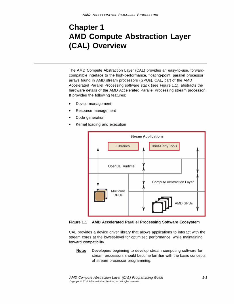
The AMD Compute Abstraction Layer (CAL) provides an easy-to-use, forward-compatible interface to the high-performance, floating-point, parallel processor arrays found in AMD stream processors (GPUs). CAL, part of the AMD Accelerated Parallel Processing software stack (see Figure 1.1), abstracts the hardware details of the AMD Accelerated Parallel Processing stream processor. It provides the following features:
• Device management
• Resource management
• Code generation
• Kernel loading and execution
Figure 1.1 AMD Accelerated Parallel Processing Software Ecosystem
CAL provides a device driver library that allows applications to interact with the stream cores at the lowest-level for optimized performance, while maintaining forward compatibility.
Note: Developers beginning to develop stream computing software for stream processors should become familiar with the basic concepts of stream processor programming.
Stream Applications
Third-Party Tools
Compute Abstraction Layer
AMD GPUs
MulticoreCPUs
Libraries
OpenCL Runtime
A M D A C C E L E R A T E D P A R A L L E L P R O C E S S I N G
1-2 Chapter 1- CAL System ArchitectureCopyright © 2010 Advanced Micro Devices, Inc. All rights reserved.
The CAL API is ideal for performance-sensitive developers because it minimizes software overhead and provides full-control over hardware-specific features that might not be available with higher-level tools.
The following subsections provide an overview of the CAL system architecture, stream processor architecture, and the execution model that it provides to the application.
1.1 CAL System ArchitectureA typical CAL application includes two parts:
• a program running on the host CPU (written in C/C++), the application, and
• a program running on the stream processor, the kernel (written in a high-level language, such as AMD IL).
The CAL API comprises one or more stream processors connected to one or more CPUs by a high-speed bus. The CPU runs the CAL and controls the stream processor by sending commands using the CAL API. The stream processor runs the kernel specified by the application. The stream processor device driver program (CAL) runs on the host CPU.
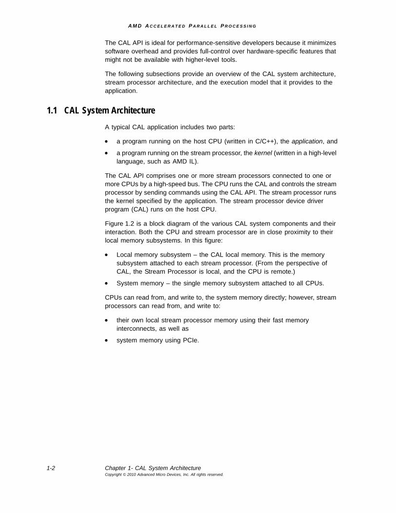
Figure 1.2 is a block diagram of the various CAL system components and their interaction. Both the CPU and stream processor are in close proximity to their local memory subsystems. In this figure:
• Local memory subsystem – the CAL local memory. This is the memory subsystem attached to each stream processor. (From the perspective of CAL, the Stream Processor is local, and the CPU is remote.)
• System memory – the single memory subsystem attached to all CPUs.
CPUs can read from, and write to, the system memory directly; however, stream processors can read from, and write to:
• their own local stream processor memory using their fast memory interconnects, as well as
• system memory using PCIe.
A M D A C C E L E R A T E D P A R A L L E L P R O C E S S I N G
CAL System Architecture 1-3Copyright © 2010 Advanced Micro Devices, Inc. All rights reserved.
Figure 1.2 CAL System Architecture
The CAL runtime allows managing multiple stream processors directly from the host application. This lets applications divide computational tasks among multiple parallel execution units and scale the application in terms of computational performance and available resources. With CAL, applications control the task of partitioning the problem and scheduling among different stream processors (see Chapter 7, “Advanced Topics.”)
1.1.1 CAL Device
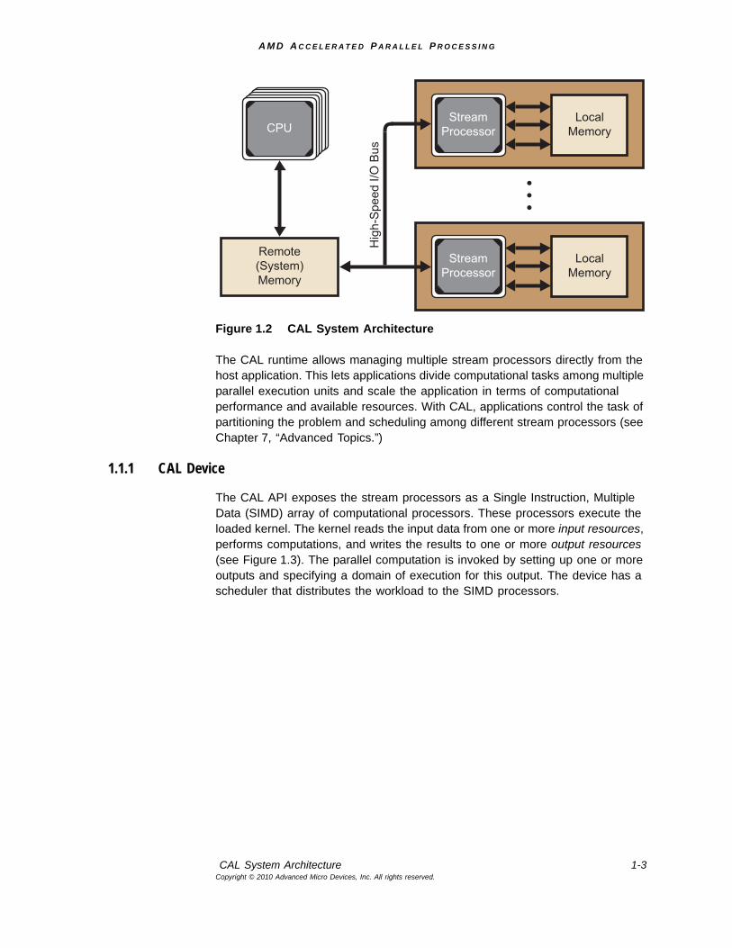
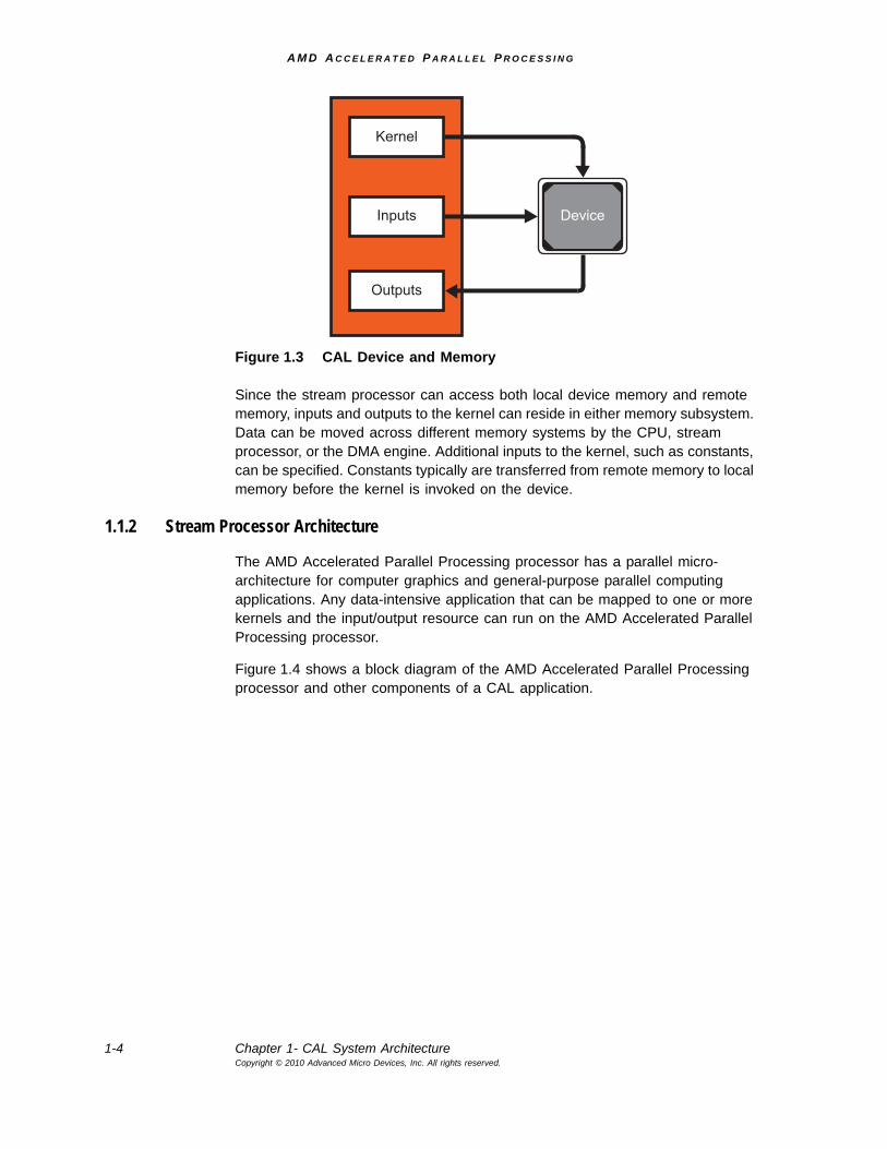
The CAL API exposes the stream processors as a Single Instruction, Multiple Data (SIMD) array of computational processors. These processors execute the loaded kernel. The kernel reads the input data from one or more input resources, performs computations, and writes the results to one or more output resources (see Figure 1.3). The parallel computation is invoked by setting up one or more outputs and specifying a domain of execution for this output. The device has a scheduler that distributes the workload to the SIMD processors.
Remote(System)Memory
LocalMemory
StreamProcessor
LocalMemory
StreamProcessor
Hig
h-S
peed
I/O
Bus
CPU
A M D A C C E L E R A T E D P A R A L L E L P R O C E S S I N G
1-4 Chapter 1- CAL System ArchitectureCopyright © 2010 Advanced Micro Devices, Inc. All rights reserved.
Figure 1.3 CAL Device and Memory
Since the stream processor can access both local device memory and remote memory, inputs and outputs to the kernel can reside in either memory subsystem. Data can be moved across different memory systems by the CPU, stream processor, or the DMA engine. Additional inputs to the kernel, such as constants, can be specified. Constants typically are transferred from remote memory to local memory before the kernel is invoked on the device.
1.1.2 Stream Processor Architecture
The AMD Accelerated Parallel Processing processor has a parallel micro-architecture for computer graphics and general-purpose parallel computing applications. Any data-intensive application that can be mapped to one or more kernels and the input/output resource can run on the AMD Accelerated Parallel Processing processor.
Figure 1.4 shows a block diagram of the AMD Accelerated Parallel Processing processor and other components of a CAL application.
Kernel
Inputs
Outputs
Device
A M D A C C E L E R A T E D P A R A L L E L P R O C E S S I N G
CAL System Architecture 1-5Copyright © 2010 Advanced Micro Devices, Inc. All rights reserved.
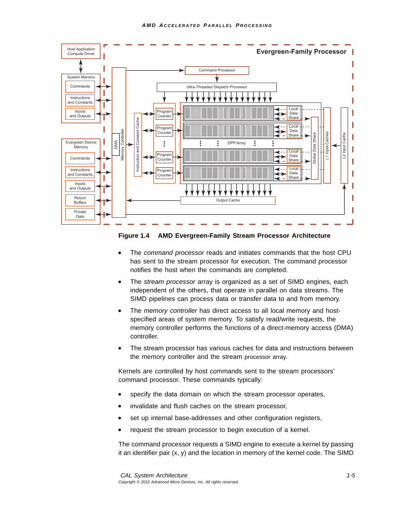
Figure 1.4 AMD Evergreen-Family Stream Processor Architecture
• The command processor reads and initiates commands that the host CPU has sent to the stream processor for execution. The command processor notifies the host when the commands are completed.
• The stream processor array is organized as a set of SIMD engines, each independent of the others, that operate in parallel on data streams. The SIMD pipelines can process data or transfer data to and from memory.
• The memory controller has direct access to all local memory and host-specified areas of system memory. To satisfy read/write requests, the memory controller performs the functions of a direct-memory access (DMA) controller.
• The stream processor has various caches for data and instructions between the memory controller and the stream processor array.
Kernels are controlled by host commands sent to the stream processors’ command processor. These commands typically:
• specify the data domain on which the stream processor operates,
• invalidate and flush caches on the stream processor,
• set up internal base-addresses and other configuration registers,
• request the stream processor to begin execution of a kernel.
The command processor requests a SIMD engine to execute a kernel by passing it an identifier pair (x, y) and the location in memory of the kernel code. The SIMD
Host ApplicationCompute Driver
System Memory
Commands
Instructionsand Constants
Inputsand Outputs
Evergreen DeviceMemory
Commands
Instructionsand Constants
Inputsand Outputs
ReturnBuffers
PrivateData
Command Processor
Ultra-Threaded Dispatch Processor
Output Cache
Inst
ruct
ion
and
Con
stan
t Cac
he
Evergreen-Family Processor
DM
A
Mem
ory
Con
trolle
r
L1 In
put C
ache
s
L2 In
put C
ache
DPP Array
ProgramCounter
ProgramCounter
ProgramCounter
ProgramCounter
Glo
bal D
ata
Sha
re
LocalData
Share
LocalData
Share
LocalData
Share
LocalData
Share
Host ApplicationCompute Driver
System Memory
Commands
Instructionsand Constants
Inputsand Outputs
Evergreen DeviceMemory
Commands
Instructionsand Constants
Inputsand Outputs
ReturnBuffers
PrivateData
Command Processor
Ultra-Threaded Dispatch Processor
Output Cache
Inst
ruct
ion
and
Con
stan
t Cac
he
Evergreen-Family Processor
DM
A
Mem
ory
Con
trolle
r
L1 In
put C
ache
s
L2 In
put C
ache
DPP Array
ProgramCounter
ProgramCounter
ProgramCounter
ProgramCounter
Glo
bal D
ata
Sha
re
LocalDataShare
LocalDataShare
LocalDataShare
LocalDataShare
A M D A C C E L E R A T E D P A R A L L E L P R O C E S S I N G
1-6 Chapter 1- CAL Programming ModelCopyright © 2010 Advanced Micro Devices, Inc. All rights reserved.
pipeline then loads instructions and data from memory, begins execution, and continues until the end of the kernel.
Conceptually, each SIMD pipeline maintains a separate interface to memory, consisting of index pairs and a field identifying the type of request (kernel instruction, floating-point constant, integer constant, input read, or output write)1. The index pairs for inputs, outputs, and constants are specified by the requesting stream processor instructions from the hardware-maintained kernel state in the pipelines.
The stream processor memory is high-speed DRAM connected to the SIMD engines using a high-speed proprietary interconnect. A host application (running on the CPU) cannot write to stream processor local memory directly, but it can command the stream processor to copy data from system (CPU) memory to stream processor memory, or vice versa.
1.2 CAL Programming ModelCAL provides access to the AMD GPU by offering the runtime and code generation services detailed in the following subsections.
1.2.1 Run Time Services
The CAL runtime library, aticalrt, can load and execute the binary image generated by the compiler. The runtime implements:
• Device Management: CAL runtime identifies all valid CAL devices on the system. It lets the application query individual device parameters and establish a connection to the device for further operations.
• Resource Management: CAL runtime handles the management of all resources, including memory pools available on the system. Memory can be allocated on device local and remote memory subsystems. Data buffers can be efficiently moved between subsystems using DMA transfers.
• Kernel Loading and Execution: CAL runtime manages the device state and lets applications set various parameters required for the kernel execution. It provides mechanisms for loading binary images on devices as modules, executing these modules, and synchronizing the execution with the application process.
1.2.2 Code Generation Services
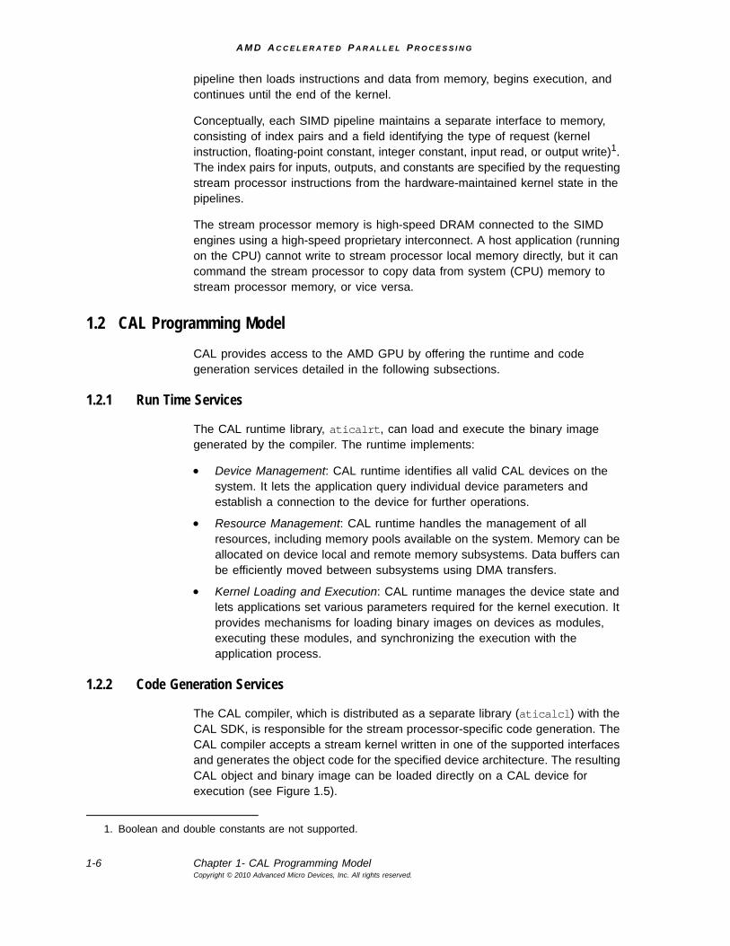
The CAL compiler, which is distributed as a separate library (aticalcl) with the CAL SDK, is responsible for the stream processor-specific code generation. The CAL compiler accepts a stream kernel written in one of the supported interfaces and generates the object code for the specified device architecture. The resulting CAL object and binary image can be loaded directly on a CAL device for execution (see Figure 1.5).
1. Boolean and double constants are not supported.
A M D A C C E L E R A T E D P A R A L L E L P R O C E S S I N G
CAL Software Distribution 1-7Copyright © 2010 Advanced Micro Devices, Inc. All rights reserved.
Figure 1.5 CAL Code Generation
The CAL API allows developing stream kernels directly using:
• Device-specific Instruction Set Architecture.
• Pseudo-Assembly languages such as the AMD Intermediate Language (IL).
The kernel can be developed in a device-independent manner using the AMD IL. It also is possible to program in a C-like high-level language. See the “Compute Kernel” section of the AMD Accelerated Parallel Processing OpenCL Programming Guide for more information on such tools.
1.3 CAL Software DistributionThe distribution software bundle consists of the CAL SDK, which includes platform-specific binaries, header files, sample code, and documentation. This document assumes that the reader has installed the CAL SDK.
On Windows®, the CAL SDK is installed in the %SystemDrive%\Program Files\ATI\ATI CAL x.x.x directory, where xxx refers to the software version currently installed. The following sections refer to the installation location of the CAL SDK as $(CALROOT) and use UNIX-style filepaths for relative paths to specific components.
Application
External Tools for High-Level Language Translation
AMD IL
CAL Compiler
Processor-specific ISA
A M D A C C E L E R A T E D P A R A L L E L P R O C E S S I N G
1-8 Chapter 1- CAL Software DistributionCopyright © 2010 Advanced Micro Devices, Inc. All rights reserved.
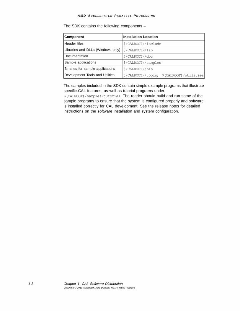
The SDK contains the following components –
The samples included in the SDK contain simple example programs that illustrate specific CAL features, as well as tutorial programs under $(CALROOT)/samples/tutorial. The reader should build and run some of the sample programs to ensure that the system is configured properly and software is installed correctly for CAL development. See the release notes for detailed instructions on the software installation and system configuration.
Component Installation Location
Header files $(CALROOT)/include
Libraries and DLLs (Windows only) $(CALROOT)/lib
Documentation $(CALROOT)/doc
Sample applications $(CALROOT)/samples
Binaries for sample applications $(CALROOT)/bin
Development Tools and Utilities $(CALROOT)/tools, $(CALROOT)/utilities
A M D A C C E L E R A T E D P A R A L L E L P R O C E S S I N G
AMD Compute Abstraction Layer (CAL) Programming Guide 2-1Copyright © 2010 Advanced Micro Devices, Inc. All rights reserved.
Chapter 2AMD CAL Application Programming Interface
The CAL API contains a few C function calls and simple data types used for data specification and processing on the device. The complete list of all functions, along with their C declarations, are in the “Compute Kernel” section of the AMD Accelerated Parallel Processing OpenCL Programming Guide. Note the following conventions regarding the CAL API:
• All CAL runtime functions use the prefix cal. All CAL compiler functions use the prefix calcl.
• All CAL utilities use the prefix calut.
• All CAL extensions use the prefix calext.
• All CAL data types are prefixed with CAL. The data types are either typedefs to built-in C types, or enums.
• CAL functions return a status code, CALresult. This can be used to check for any internal or usage error within the function. (The exception is disassemble functions, which use calcldisassemble[image|object].) On success, all functions return CAL_RESULT_OK. The calGetErrorString function provides more information about the error in a human readable string.
• CAL uses opaque handles for internal data structures like CALdevice and CALresource.
The following sections provide more information about the two main components of the API: the CAL runtime, and the CAL compiler. The list of CAL compiler and runtime function calls is in “Compute Kernel” section of the AMD Accelerated Parallel Processing OpenCL Programming Guide.
2.1 CAL RuntimeThe CAL runtime comprises:
• System initialization and query
• Device management
• Context management
• Memory management,
• Program loading
• Program execution
A M D A C C E L E R A T E D P A R A L L E L P R O C E S S I N G
2-2 Chapter 2- CAL RuntimeCopyright © 2010 Advanced Micro Devices, Inc. All rights reserved.
This section covers the first four bulleted items. The last two components, program loading and program execution, are covered in Section 2.3, “Kernel Execution,” page 2-10.
2.1.1 CAL Linux Runtime Options
Note the following for CAL when running under Linux.
• DISPLAY - Ensure this is set to 0.0 to point CAL at the local X Windows server. CAL accesses the GPU through the X Windows server on the local machine.
• On Linux, the rendering display connection must be separate from the compute display connection. It is possible to send my XRequests to one display while using the GPU attached to another display. A COMPUTE environment variable establishes the GPU display connection.
If the screen number is specified, only the GPU attached to that screen is listed (instead of reordering the GPUs). For example, if DISPLAY or COMPUTE == :0, all GPUs are listed; but if DISPLAY or COMPUTE == :0.N, only GPU N is reported. This maintains compatibility with prior CAL versions.
• Ensure your current login session has permission to access the local X Windows server. Do this by logging into the X Windows console locally. If you must access the machine remotely, ensure that your remote session has access rights to the local X Windows server.
2.1.2 CAL System Initialization and Query
The CAL runtime provides mechanisms for initializing, and shutting down, a CAL system. It also contains methods to query the version of the CAL runtime.
The first CAL routine to be invoked from an application is calInit. It initializes the CAL API and identifies all valid CAL devices on the system. Invoking any other CAL function prior to calInit results in an error code, CAL_RESULT_ERROR. If calInit has already been invoked, the routine returns CAL_RESULT_ALREADY. Similarly, calShutdown must be called before the application exits for the application to shutdown properly. Invoking another CAL routine after calShutdown results in a CAL_RESULT_NOT_INITIALIZED error.
Query the CAL version on the system with the calGetVersion routine. It provides the major and minor version numbers of the CAL release, as well as the implementation instance of the supplied version number.
2.1.3 CAL Device Management
The CAL runtime supports managing multiple devices in the system. The CAL API identifies each device in the system with a unique numeric identifier in the range [0...N-1], where N is the number of CAL-supported devices on the system. To find the number of stream processors in the system use the calDeviceGetCount routine (see the FindNumDevices tutorial program). For further information on each device, use the calDeviceGetInfo routine. It returns
A M D A C C E L E R A T E D P A R A L L E L P R O C E S S I N G
CAL Runtime 2-3Copyright © 2010 Advanced Micro Devices, Inc. All rights reserved.
information on the specific device, including the device type and maximum valid dimensions of 1D and 2D buffer resources that can be allocated on this device.
Before any operations can be done on a given CAL device, the application must open a dedicated connection to the device using the calDeviceOpen routine. Similarly, the device must be closed before the application exits using the calDeviceClose routine (see the OpenCloseDevice tutorial program).
The calDeviceOpen routine accepts the numeric identifier for the stream processor that must be opened; when it is open, the routine returns a pointer to the device.
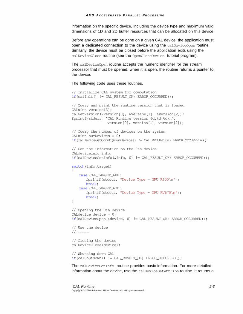
The following code uses these routines.
// Initialize CAL system for computationif(calInit() != CAL_RESULT_OK) ERROR_OCCURRED();
// Query and print the runtime version that is loadedCALuint version[3];calGetVersion(&version[0], &version[1], &version[2]);fprintf(stderr, “CAL Runtime version %d.%d.%d\n”,
version[0], version[1], version[2]);
// Query the number of devices on the systemCALuint numDevices = 0;if(calDeviceGetCount(&numDevices) != CAL_RESULT_OK) ERROR_OCCURRED();
// Get the information on the 0th deviceCALdeviceinfo info;if(calDeviceGetInfo(&info, 0) != CAL_RESULT_OK) ERROR_OCCURRED();
switch(info.target){
case CAL_TARGET_600:fprintf(stdout, "Device Type = GPU R600\n");break;
case CAL_TARGET_670:fprintf(stdout, "Device Type = GPU RV670\n");break;
}
// Opening the 0th deviceCALdevice device = 0;if(calDeviceOpen(&device, 0) != CAL_RESULT_OK) ERROR_OCCURRED();
// Use the device// ……………
// Closing the devicecalDeviceClose(device);
// Shutting down CALif(calShutdown() != CAL_RESULT_OK) ERROR_OCCURRED();
The calDeviceGetInfo routine provides basic information. For more detailed information about the device, use the calDeviceGetAttribs routine. It returns a
A M D A C C E L E R A T E D P A R A L L E L P R O C E S S I N G
2-4 Chapter 2- CAL RuntimeCopyright © 2010 Advanced Micro Devices, Inc. All rights reserved.
C struct of type CALdeviceattribs with fields of information on the stream processor ASIC type, available local and remote RAM sizes, and stream processor clock speed. Note, however, that setting struct.struct_size to the size of CALdeviceattribs must be done before calling calDeviceGetAttribs.
2.1.4 CAL Context Management
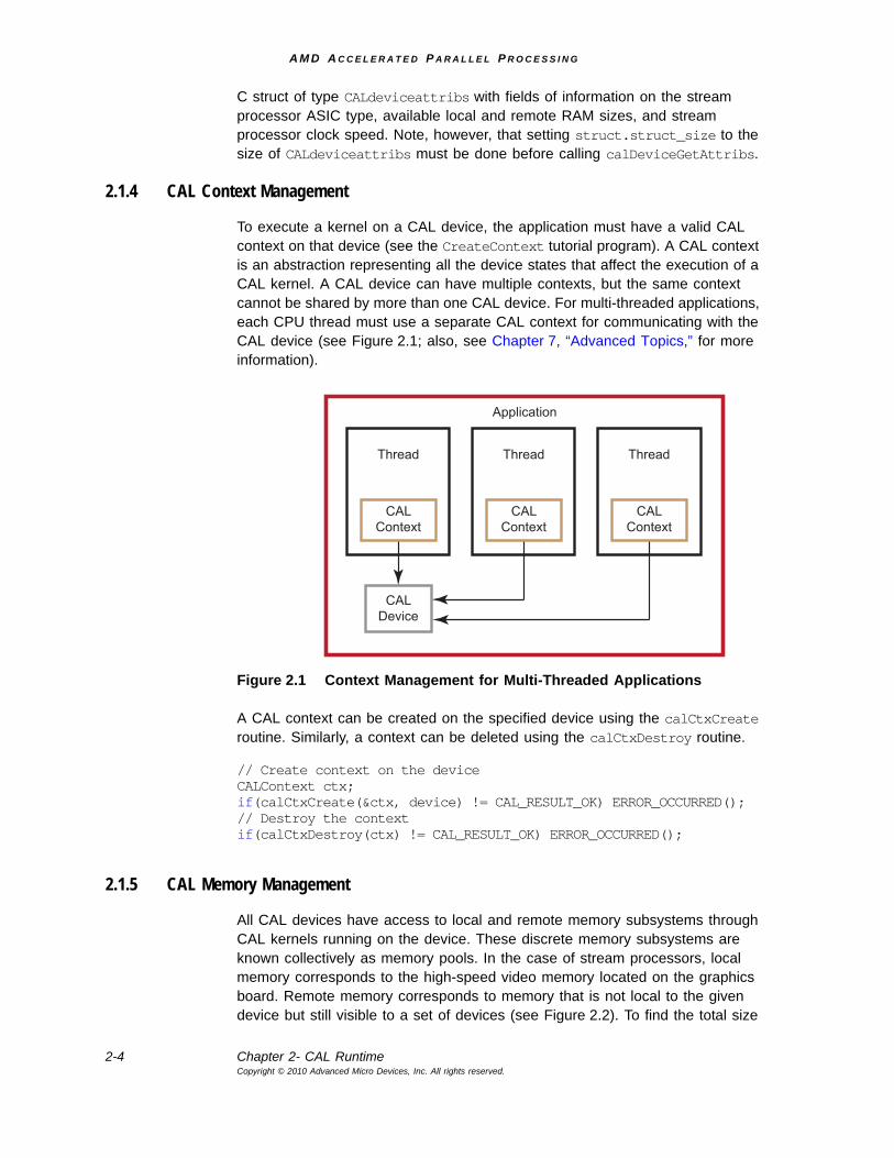
To execute a kernel on a CAL device, the application must have a valid CAL context on that device (see the CreateContext tutorial program). A CAL context is an abstraction representing all the device states that affect the execution of a CAL kernel. A CAL device can have multiple contexts, but the same context cannot be shared by more than one CAL device. For multi-threaded applications, each CPU thread must use a separate CAL context for communicating with the CAL device (see Figure 2.1; also, see Chapter 7, “Advanced Topics,” for more information).
Figure 2.1 Context Management for Multi-Threaded Applications
A CAL context can be created on the specified device using the calCtxCreate routine. Similarly, a context can be deleted using the calCtxDestroy routine.
// Create context on the deviceCALContext ctx;if(calCtxCreate(&ctx, device) != CAL_RESULT_OK) ERROR_OCCURRED(); // Destroy the contextif(calCtxDestroy(ctx) != CAL_RESULT_OK) ERROR_OCCURRED();
2.1.5 CAL Memory Management
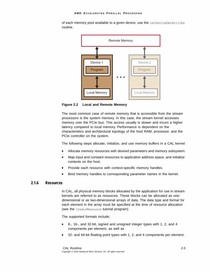
All CAL devices have access to local and remote memory subsystems through CAL kernels running on the device. These discrete memory subsystems are known collectively as memory pools. In the case of stream processors, local memory corresponds to the high-speed video memory located on the graphics board. Remote memory corresponds to memory that is not local to the given device but still visible to a set of devices (see Figure 2.2). To find the total size
Application
CALDevice
Thread
CALContext
Thread
CALContext
Thread
CALContext
A M D A C C E L E R A T E D P A R A L L E L P R O C E S S I N G
CAL Runtime 2-5Copyright © 2010 Advanced Micro Devices, Inc. All rights reserved.
of each memory pool available to a given device, use the calDeviceGetAttribs routine.
Figure 2.2 Local and Remote Memory
The most common case of remote memory that is accessible from the stream processors is the system memory. In this case, the stream kernel accesses memory over the PCIe bus. This access usually is slower and incurs a higher latency compared to local memory. Performance is dependent on the characteristics and architectural topology of the host RAM, processor, and the PCIe controller on the system.
The following steps allocate, initialize, and use memory buffers in a CAL kernel:
• Allocate memory resources with desired parameters and memory subsystem.
• Map input and constant resources to application address space, and initialize contents on the host.
• Provide each resource with context-specific memory handles.
• Bind memory handles to corresponding parameter names in the kernel.
2.1.6 Resources
In CAL, all physical memory blocks allocated by the application for use in stream kernels are referred to as resources. These blocks can be allocated as one-dimensional or as two-dimensional arrays of data. The data type and format for each element in the array must be specified at the time of resource allocation (see the CreateResource tutorial program).
The supported formats include:
• 8-, 16-, and 32-bit, signed and unsigned integer types with 1, 2, and 4 components per element, as well as
• 32- and 64-bit floating point types with 1, 2, and 4 components per element.
Remote Memory
Device 1
Program
Local Memory
Device 2
Program
Local Memory
A M D A C C E L E R A T E D P A R A L L E L P R O C E S S I N G
2-6 Chapter 2- CAL RuntimeCopyright © 2010 Advanced Micro Devices, Inc. All rights reserved.
The formats are specified using the CALformat enumerated type (see Section A.5.1, “Types,” page A-30).
The enums use the naming syntax CAL_FORMAT_type_n, where type is the data type and n is the number of components per element. For example, CAL_FORMAT_UNORM_INT8_4 represents an element with four 8-bit unsigned integer values per element.
Note: Four-component 64-bit floating point types are not supported with this version of the CAL release. When a resource of format 8-bit or 16-bit integer is sampled inside a kernel, the fetched data is auto-matically converted to normalized floating point. The developer can choose to convert the fetched data back to 8-bit or 16-bit integer inside the IL kernel, or continue to use it as floating point. Similarly, when writing to a resource of format 8-bit or 16-bit integer, the data being written is expected to be in normalized floating point. This data is automatically converted to 8-bit or 16-bit integer, as appro-priate, before it is written to the resource.
Memory can be allocated locally (stream processor memory) or remotely (system memory). In the case of remote allocation, the CAL API lets the application control the list of devices that can access the resource directly. Remote memory can serve as a mechanism for sharing memory resources between multiple devices. This prevents the application from having to create multiple copies of the data.
Local resources can be allocated using the calResAllocLocalnD routines, where n is the dimension of the array. Currently, n can be only 1 or 2. The routine requires the application to pass the CALDevice on which the resource is allocated along with other parameters such as width, height, format, etc. Similarly, remote resources are allocated using the calResAllocRemotenD routines and require the list of CAL devices that can share the remote resource. The allocated resource is visible only to these devices. On successful completion of the allocation, the CAL API returns a pointer to the newly allocated CALResource. To deallocate a resource, use the calResFree routine.
1D resources allocated with the GLOBAL_BUFFER flag set can allocate any size buffer. If this flag is not set, CAL assumes it is used as an input and rejects any size > maxResource1DWidth.
The following code allocates a 2D resource of 32-bit floating point values on the specified CAL device.
// Allocate 2D array of FLOAT_1 dataCALresource resLocal = 0;if(calResAllocLocal2D(&resLocal, device, width, height,
CAL_FORMAT_FLOAT32_1, 0) != CAL_RESULT_OK)ERROR_OCCURRED();
// Do the computations// ……………
A M D A C C E L E R A T E D P A R A L L E L P R O C E S S I N G
CAL Runtime 2-7Copyright © 2010 Advanced Micro Devices, Inc. All rights reserved.
// De-allocate the resourceif(calResFree(resLocal) != CAL_RESULT_OK) ERROR_OCCURRED();
CAL memory is used as inputs, outputs, or constants to CAL kernels. For inputs and constants, first initialize the contents of the memory buffer from the host application. One way to do this is to map the memory to the application’s address space using the calResMap routine. The routine returns a host-side memory pointer that the application can dereference; the application then initializes the buffer. The routine also returns the pitch of the data buffer, which must be considered when dereferencing this data. The pitch corresponds to the number of elements in each row of the resource. This usually is equal to, or greater than, the width specified in the allocation routine. The size of the memory buffer allocated is given by:
Allocated Buffer Size = Pitch * Height * Number of components *Size of data type
The following code demonstrates how to use calResMap to initialize the resource allocated above.
// Map the memory handle to CPU pointerfloat *dataPtr = NULL;CALuint pitch = 0;if(calResMap((CALVoid **)&dataPtr, &pitch, resLocal, 0) !=
CAL_RESULT_OK) ERROR_OCCURRED();
// Initialize the data valuesfor(int i = 0; i < height; i++){
// Note the use of the pitch returned by calResMap to properly// offset into the memory pointerfloat* tmp = &dataPtr[i * pitch];
for (int j = 0; j < width; j++){
// At this place depending on the format (1,2,4) we can// specify relevant values i.e.// For FLOAT_1, we should initialize temp[j]// For FLOAt_2, we should initialize temp[2*j] & temp[2*j + 1]// For FLOAT_4, we should initialize temp[4*j], temp[4*j + 1],// temp[4*j + 2] & temp[4*j + 3]
tmp[j] = (float)(i * width + j);}
}
// Unmap the memory handleif(calResUnmap(resLocal) != CAL_RESULT_OK) ERROR_OCCURRED();
Note that a mapped resource cannot be used in a CAL kernel; the resource must be unmapped using calResUnmap before being used as shown above.
2.1.7 Memory Handles
Once a resource has been allocated, it must be bound to a given CAL context before being used in a CAL kernel. CAL resources are not context-specific.
A M D A C C E L E R A T E D P A R A L L E L P R O C E S S I N G
2-8 Chapter 2- CAL CompilerCopyright © 2010 Advanced Micro Devices, Inc. All rights reserved.
Hence, they first must be mapped to the given context’s address space before being addressed by that context. This is done using the calCtxGetMem routine. When this is done, the routine returns a context-specific memory handle to the resource. This handle can be used for subsequent operations, such as reading from, and writing to, the resource. Once the memory handle is no longer needed, the handle can be released using the calCtxReleaseMem routine.
// Map the given resource to a new memory handle for this contextCALmem memLocal = 0;if(calCtxGetMem(&memLocal, ctx, resLocal) != CAL_RESULT_OK)
ERROR_OCCURRED();
// Use the memory handle// ………………
// Release the resource to context mappingif(calCtxReleaseMem(ctx, memLocal) != CAL_RESULT_OK) ERROR_OCCURRED();
The SetupData routine in the basic tutorial program implements the steps required to allocate, initialize, and use memory buffers in a kernel. The last step of binding memory handles to kernel names and parameter names is explained in Section 2.3, “Kernel Execution.”
2.2 CAL CompilerThe CAL compiler provides a high-level runtime interface for compiling stream kernels written in one of the supported programming interfaces. The compiler can be invoked either at runtime or offline. Invoking them at runtime typically happens during kernel development when the developer constantly modifies the kernel and tests the output results. Invoking the offline compiler is suitable for production-class applications, including kernels that have already been developed and are loaded and invoked only at runtime. This mechanism prevents the overhead of compiling the kernel each time the application is executed.
AMD provides other useful tools that can be used for fast and easy development of efficient stream kernels. See the “Compute Kernel” and “Stream KernelAnalyzer” sections of the AMD Accelerated Parallel Processing OpenCL Programming Guide for more information.
2.2.1 Compilation and Linking
The CAL compiler accepts the kernel in one of the supported programming interfaces and generates a binary object specific to a given target CAL device using calclCompile (see the CompileProgram tutorial program). The routine requires the application to specify, as arguments, the interface type and the target device architecture for the resulting binary object, along with the C-style string for the stream kernel. Once compiled, the object must be linked into a binary image using calclLink, which generates this image. The binary object and image are returned as the handles CALobject and CALimage, respectively.
A M D A C C E L E R A T E D P A R A L L E L P R O C E S S I N G
CAL Compiler 2-9Copyright © 2010 Advanced Micro Devices, Inc. All rights reserved.
Note the following guidelines for the CAL compiler API:
• Only the AMD IL and the stream processor-specific Instruction Set Architecture (ISA) are supported as the runtime programming interfaces by calclCompile.
• The target device architecture supported includes AMD GPUs listed under the CALtarget enumerated type.
The following code shows the use of the CAL compiler API for querying the compiler version, compiling a minimal AMD IL kernel and linking the resulting object into the final binary image. Note the use of the calclFreeObject and calclFreeImage routines for deallocating the memory allocated by the CAL compiler for the program object and binary image.
// Kernel stringconst char ilKernel[] ="il_ps_2_0 \n"// other instructions"ret_dyn \n""end \n";
// Query and print the compiler version that is loadedCALuint version[3];calclGetVersion(&version[0], &version[1], &version[2]);fprintf(stderr, "CAL Compiler version %d.%d.%d\n",
version[0], version[1], version[2]);
// Compile the IL kernelCALobject object = NULL;if(calclCompile(&object, CAL_LANGUAGE_IL, ilKernel, CAL_TARGET_670) !=
CAL_RESULT_OK))ERROR_OCCURRED();
// Link the objects into CAL imageCALimage image = NULL;if(calclLink (&image, &object, 1) != CAL_RESULT_OK))
ERROR_OCCURRED();
// Use the CAL runtime API to load and run the kernel// ……………
// Free the objectcalclFreeObject(object);
// Free the imagecalclFreeImage(image);
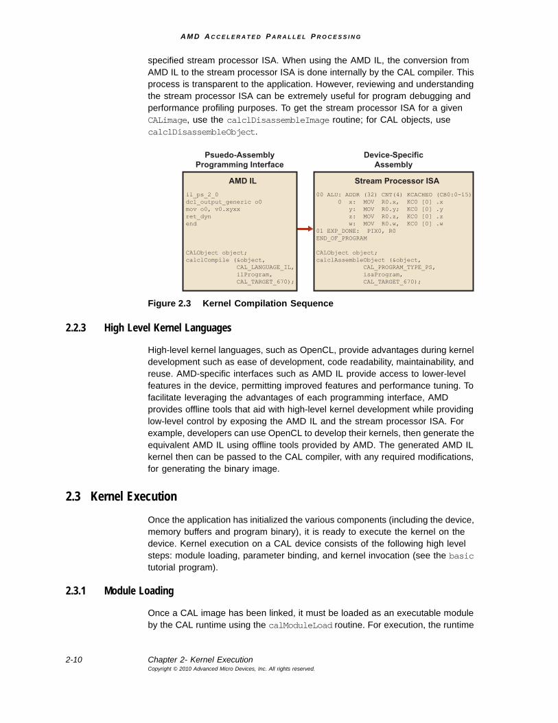
2.2.2 Stream Processor ISA
The CAL compiler compiles and optimizes the input AMD IL pseudo-assembly to generate the stream processor-specific ISA. The developer can use the AMD IL or the stream processor ISA for developing the kernel. Figure 2.3 illustrates the sequence of steps used during the compilation process. Note that this routine performs no optimizations, and the resulting binary is a direct mapping of the
A M D A C C E L E R A T E D P A R A L L E L P R O C E S S I N G
2-10 Chapter 2- Kernel ExecutionCopyright © 2010 Advanced Micro Devices, Inc. All rights reserved.
specified stream processor ISA. When using the AMD IL, the conversion from AMD IL to the stream processor ISA is done internally by the CAL compiler. This process is transparent to the application. However, reviewing and understanding the stream processor ISA can be extremely useful for program debugging and performance profiling purposes. To get the stream processor ISA for a given CALimage, use the calclDisassembleImage routine; for CAL objects, use calclDisassembleObject.
Figure 2.3 Kernel Compilation Sequence
2.2.3 High Level Kernel Languages
High-level kernel languages, such as OpenCL, provide advantages during kernel development such as ease of development, code readability, maintainability, and reuse. AMD-specific interfaces such as AMD IL provide access to lower-level features in the device, permitting improved features and performance tuning. To facilitate leveraging the advantages of each programming interface, AMD provides offline tools that aid with high-level kernel development while providing low-level control by exposing the AMD IL and the stream processor ISA. For example, developers can use OpenCL to develop their kernels, then generate the equivalent AMD IL using offline tools provided by AMD. The generated AMD IL kernel then can be passed to the CAL compiler, with any required modifications, for generating the binary image.
2.3 Kernel ExecutionOnce the application has initialized the various components (including the device, memory buffers and program binary), it is ready to execute the kernel on the device. Kernel execution on a CAL device consists of the following high level steps: module loading, parameter binding, and kernel invocation (see the basic tutorial program).
2.3.1 Module Loading
Once a CAL image has been linked, it must be loaded as an executable module by the CAL runtime using the calModuleLoad routine. For execution, the runtime
Device-SpecificAssembly
il_ps_2_0dcl_output_generic o0mov o0, v0.xyxxret_dynend
CALObject object;calclCompile (&object, CAL_LANGUAGE_IL, ilProgram, CAL_TARGET_670);
AMD IL
Psuedo-AssemblyProgramming Interface
Stream Processor ISA00 ALU: ADDR (32) CNT(4) KCACHEO (CB0:0-15) 0 x: MOV R0.x, KC0 [0] .x y: MOV R0.y; KC0 [0] .y z: MOV R0.z, KC0 [0] .z w: MOV R0.w, KC0 [0] .w01 EXP_DONE: PIX0, R0END_OF_PROGRAM
CALObject object;calclAssembleObject (&object, CAL_PROGRAM_TYPE_PS, isaProgram, CAL_TARGET_670);
A M D A C C E L E R A T E D P A R A L L E L P R O C E S S I N G
Kernel Execution 2-11Copyright © 2010 Advanced Micro Devices, Inc. All rights reserved.
must specify the entry point within the module. This can be queried using the function name in the original kernel string. Currently, the function name is always set to main. The following code is an example of loading an executable module.
// Load CAL image as a runtime module for this contextCALmodule module = 0;if(calModuleLoad(&module, ctx, image) != CAL_RESULT_OK)
ERROR_OCCURRED();
// Query the entry point in the module for the function “main”CALfunc entry = 0;if(calModuleGetEntry(&entry, ctx, module, "main") != CAL_RESULT_OK)
ERROR_OCCURRED();
2.3.2 Parameter Binding
The CAL runtime API also provides an interface to set up various parameters (inputs and outputs) required by the CAL API for proper execution. CAL identifies each parameter in the module by its variable name in the original kernel string. These variables are AMD IL-style names for inputs (i#), outputs (o#), and constant buffers (cb#), as shown in the following code. The runtime provides a routine, calModuleGetName, that allows retrieving a handle from each of the variables in the module as CALname. Here, uav# (Evergreen-family GPUs only) is for unordered-access views, x#[ ] is for the scratch buffer, g[ ] is for the global buffer, i# is for the input buffer, and o# is for the output buffer. These parameter name handles subsequently can be bound to specific memory handles using calCtxSetMem, then used by the CAL kernel at runtime. The following code is an example of binding parameters.
// Query the variable names for input 0 and output 0CALname input = 0, output = 0;if(calModuleGetName(&input, ctx, module, "i0") != CAL_RESULT_OK ||
calModuleGetName(&output, ctx, module, "o0") != CAL_RESULT_OK)ERROR_OCCURRED();
CALmem inputMem = 0, outputMem = 0;
// Bind resources to memory handles for this context// ……………
// Bind the parameters to memory handlesif(calCtxSetMem(ctx, input, inputMem) != CAL_RESULT_OK ||
calCtxSetMem(ctx, output, outputMem) != CAL_RESULT_OK)ERROR_OCCURRED();
2.3.3 Kernel Invocation
Kernels are executed over a rectangular region of the output buffer called the domain of execution. The kernel is launched using the calCtxRunProgram routine, which specifies the context, entry point, and domain of execution. The routine returns an event identifier for this invocation. The calCtxRunProgram routine is a non-blocking routine and returns immediately. The application thread
A M D A C C E L E R A T E D P A R A L L E L P R O C E S S I N G
2-12 Chapter 2- Kernel ExecutionCopyright © 2010 Advanced Micro Devices, Inc. All rights reserved.
calling this routine is free to execute other tasks while the computation is being done on the CAL device. Alternatively, the application thread can use a busy-wait loop to keep polling on the completion of the event by using the calCtxIsEventDone routine. The following code is an example of invoking a kernel.
// Setup the domain for executionCALdomain domain = {0, 0, width, height};
// Event ID corresponding to the kernel invocationCALevent event = 0;
// Launch the CAL kernel on the given domainif(calCtxRunProgram(&event, ctx, entry, &domain) != CAL_RESULT_OK)
ERROR_OCCURRED();
// Wait on the event for kernel completionwhile(calCtxIsEventDone(ctx, event) == CAL_RESULT_PENDING);
When the above loop returns, the stream kernel has finished execution, and the output memory can be dereferenced (using calResMap) to access the output results. Note the following:
• The domain (domain of execution) is a subset of the output buffer. The stream processor creates a separate thread for each (x,y) location in the domain of execution.
• For improved performance, calCtxRunProgram does not immediately dispatch the program for execution on the stream processor. To force the dispatch, the application must call calCtxIsEventDone and calCtxFlush on the corresponding event.
A M D A C C E L E R A T E D P A R A L L E L P R O C E S S I N G
AMD Compute Abstraction Layer (CAL) Programming Guide 3-1Copyright © 2010 Advanced Micro Devices, Inc. All rights reserved.
Chapter 3HelloCAL Application
This chapter provides a simple example in the form of a HelloCAL application. This program demonstrates the following components:
• Initializing CAL
• Compiling and loading a stream kernel
• Opening a connection to a CAL device
• Allocating memory
• Specifying kernel parameters including inputs, outputs, and constants
• Executing the CAL kernel
HelloCAL uses a CAL kernel written in AMD IL; this shows the actions taken when running a CAL application. The kernel reads from one input, multiplies the resulting value by a constant, and writes to one output. In vector notation, the computation can be represented as:
Out(1:N) = In(1:N) * constant;
The following analyzes the major blocks of code in HelloCAL. The code provided in this section is a complete application. The reader can copy the code examples into a separate C++ file to compile and run it.
3.1 Basic Infrastructural CodeThe following code contains the basic infrastructural code, including headers used by the application. Note that cal.h and calcl.h are shipped as part of the standard CAL headers. Building HelloCAL requires the aticalrt and aticalcl libraries.
/////////////////////////////////////////////////////////////////////! Header files///////////////////////////////////////////////////////////////////#include "cal.h"#include "calcl.h"#include <string>
The reader must have a basic understanding of AMD IL. The AMD Compute Abstraction Layer (CAL) Intermediate Language (IL) Reference Manual provides a detailed specification on the AMD IL interface.
A M D A C C E L E R A T E D P A R A L L E L P R O C E S S I N G
3-2 Chapter 3- Defining the Stream KernelCopyright © 2010 Advanced Micro Devices, Inc. All rights reserved.
3.2 Defining the Stream KernelThe following code defines the stream kernel written in AMD IL.
This stream kernel:
• Looks up the 0’th input buffer via the 0’th sampler, using sample_resource(n)_sampler(m) instruction. The current fragment’s position, v0.xy, is the index into the input buffer. It stores the resulting value in temporary register r0.
• Multiplies the value in r0 with the constant cb0[0], and writes the resulting value to output buffer o0.
////////////////////////////////////////////////////////////////////////////! Device Kernel to be executed on the GPU////////////////////////////////////////////////////////////////////////////! IL Kernelstd::string kernelIL ="il_ps_2_0\n""dcl_input_position_interp(linear_noperspective) vWinCoord0.xy__\n""dcl_output_generic o0\n""dcl_cb cb0[1]\n""dcl_resource_id(0)_type(2d,unnorm)_fmtx(float)_fmty(float)_fmtz(float)_fmtw(float)\n""sample_resource(0)_sampler(0) r0, vWinCoord0.xyxx\n""mul o0, r0, cb0[0]\n""end\n";
};
3.3 Application CodeThe following code contains the actual application code that initializes CAL, queries the number of devices on the given system, and opens a connection to the 0’th CAL device. The application then creates a CAL context on this device.
/////////////////////////////////////////////////////////////////////! Main function///////////////////////////////////////////////////////////////////int main(int argc, char** argv){
// Initializing CALcalInit();//--------------------------------------------------------------// Querying and opening device//--------------------------------------------------------------// Finding number of devicesCALuint numDevices = 0;calDeviceGetCount(&numDevices);
// Opening deviceCALdevice device = 0;calDeviceOpen(&device, 0);
// Querying device infoCALdeviceinfo info;calDeviceGetInfo(&info, 0);
// Creating context w.r.t. to opened deviceCALcontext ctx = 0;
calCtxCreate(&ctx, device);
A M D A C C E L E R A T E D P A R A L L E L P R O C E S S I N G
Compile the Stream Kernel and Link Generated Object 3-3Copyright © 2010 Advanced Micro Devices, Inc. All rights reserved.
3.4 Compile the Stream Kernel and Link Generated ObjectThe following code compiles the stream kernel using the calcl compiler; it then links the generated object files into a CALimage. Note that the stream kernel is being compiled for the AMD device queried to be present on the system using the calDeviceGetInfo routine. Also note that the calclLink routine can be used to link multiple object files into a single binary image.
//-----------------------------------------------------------------// Compiling Device Kernel//-----------------------------------------------------------------CALobject obj = NULL;CALimage image = NULL;CALlanguage lang = CAL_LANGUAGE_IL;std::string kernel = kernelIL;std::string kernelType = "IL";
if (calclCompile(&obj, lang, kernel.c_str(), info.target) != CAL_RESULT_OK)
{fprintf(stdout, "Kernel compilation failed. Exiting.\n");return 1;
}
if (calclLink(&image, &obj, 1) != CAL_RESULT_OK){
fprintf(stdout, "Kernel linking failed. Exiting.\n");return 1;
}
3.5 Allocate MemoryThe following code allocates memory for various buffers to be used by the CAL API. Note that:
• All memory buffers in the application are allocated locally to the opened CAL device. In the case of stream processors, this memory corresponds to stream processor memory.
• The input and output buffers contain one-element float values. CAL also allows elements with one, two, and four data values per element arranged in an interleaved manner. For example, CAL_FORMAT_FLOAT4 stores four floating point values per element in the buffer. This can be extremely useful in certain algorithms since it allows reading multiple values using a single read instruction.
• The resources must be mapped to CPU memory handles before they can be referenced in the application. The pitch of the buffer must be considered while dereferencing the data pointer.
• Any constants required by the kernel can be passed as a one-dimensional array of data values. This array must be allocated, mapped, and initialized similar to the way input buffers are handled. In the following code, the constant buffer is allocated in remote memory.
A M D A C C E L E R A T E D P A R A L L E L P R O C E S S I N G
3-4 Chapter 3- Preparing the Stream Kernel for ExecutionCopyright © 2010 Advanced Micro Devices, Inc. All rights reserved.
//-------------------------------------------------------------------------// Allocating and initializing resources//-------------------------------------------------------------------------// Input and output resourcesCALresource inputRes = 0;CALresource outputRes = 0;
calResAllocLocal2D(&inputRes, device, 256, 256, CAL_FORMAT_FLOAT32_1, 0);calResAllocLocal2D(&outputRes, device, 256, 256, CAL_FORMAT_FLOAT32_1, 0);
// Constant resourceCALresource constRes = 0;calResAllocRemote1D(&constRes, &device, 1, 1, CAL_FORMAT_FLOAT32_4, 0);
// Setup input buffer – map resource to CPU, initialize values, unmap resourcefloat* fdata = NULL;CALuint pitch = 0;CALmem inputMem = 0;
// Mapping resource to CPUcalResMap((CALvoid**)&fdata, &pitch, inputRes, 0);for (int i = 0; i < 256; ++i){
float* tmp = &fdata[i * pitch];for (int j = 0; j < 256; ++j){
tmp[j] = (float)(i * pitch + j);}
}calResUnmap(inputRes);
// Setup const buffer – map resource to CPU, initialize values, unmap resourcefloat* constPtr = NULL;CALuint constPitch = 0;CALmem constMem = 0;calResMap((CALvoid**)&constPtr, &constPitch, constRes, 0);constPtr[0] = 0.5f, constPtr[1] = 0.0f;constPtr[2] = 0.0f; constPtr[3] = 0.0f;calResUnmap(constRes);
// Mapping output resource to CPU and initializing valuesvoid* data = NULL;
// Getting memory handle from resourcesCALmem outputMem = 0;calResMap(&data, &pitch, outputRes, 0);memset(data, 0, pitch * 256 * sizeof(float));calResUnmap(outputRes);
// Get memory handles for various resourcescalCtxGetMem(&constMem, ctx, constRes);calCtxGetMem(&outputMem, ctx, outputRes);calCtxGetMem(&inputMem, ctx, inputRes);
3.6 Preparing the Stream Kernel for ExecutionThe following code prepares the stream kernel for execution. The CAL image is first loaded into a CALmodule. Subsequently, the names for various parameters used in the stream kernel, including the input, output, and constant buffers, are queried from the module. The names are then bound to appropriate memory handles corresponding to these parameters. Finally, the kernel’s domain of
A M D A C C E L E R A T E D P A R A L L E L P R O C E S S I N G
Kernel Execution 3-5Copyright © 2010 Advanced Micro Devices, Inc. All rights reserved.
execution is set up. In this case, the domain is the same as the dimensions of the output buffer. This is the most commonly used scenario, even though CAL allows specifying domains that are subsets of the output buffers. Note that all the settings mentioned above are collectively called the kernel state and are associated with the current CAL context.
//-----------------------------------------------------------------// Loading module and setting domain//-----------------------------------------------------------------
// Creating module using compiled imageCALmodule module = 0;calModuleLoad(&module, ctx, image);
// Defining symbols in moduleCALfunc func = 0;CALname inName = 0, outName = 0, constName = 0;
// Defining entry point for the modulecalModuleGetEntry(&func, ctx, module, "main");calModuleGetName(&inName, ctx, module, "i0");calModuleGetName(&outName, ctx, module, "o0");calModuleGetName(&constName, ctx, module, "cb0");
// Setting input and output buffers// used in the kernelcalCtxSetMem(ctx, inName, inputMem);calCtxSetMem(ctx, outName, outputMem);calCtxSetMem(ctx, constName, constMem);
// Setting domainCALdomain domain = {0, 0, 256, 256};
3.7 Kernel ExecutionOnce the above state has been set, the stream kernel can be launched using the calCtxRunProgram routine. The function main in the stream kernel is queried from the module and specified as the entry point during kernel launch. The calCtxRunProgram function returns an event identifier, CALevent, for the current kernel launch. This identifier can determine if the event has completed. Note that if a certain state setting required by the kernel is not set up before launching the kernel, the calCtxRunProgram call fails.
//-----------------------------------------------------------------// Executing kernel and waiting for kernel to terminate//-----------------------------------------------------------------
// Event to check completion of the kernelCALevent e = 0;calCtxRunProgram(&e, ctx, func, &domain);
// Checking whether the execution of the kernel is complete or notwhile (calCtxIsEventDone(ctx, e) == CAL_RESULT_PENDING);
// Reading output from output resourcescalResMap((CALvoid**)&fdata, &pitch, outputRes, 0);for (int i = 0; i < 8; ++i){
float* tmp = &fdata[i * pitch];for(int j = 0; j < 8; ++j){
printf("%f ", tmp[j]);}
A M D A C C E L E R A T E D P A R A L L E L P R O C E S S I N G
3-6 Chapter 3- De-Allocation and Releasing ConnectionsCopyright © 2010 Advanced Micro Devices, Inc. All rights reserved.
printf("\n");}calResUnmap(outputRes);
When the calCtxIsEventDone loop ends, the stream kernel has finished execution. The output memory can be dereferenced (using calMemResMap) to access the results in system memory.
3.8 De-Allocation and Releasing ConnectionsAfter the kernel execution, de-allocate the various resources, and release the connections to the device and corresponding contexts to exit the application cleanly. The following code demonstrates this process. Resource de-allocation includes:
• unbinding of memory handles (setting handle identifier as 0 in calCtxSetMem),
• releasing memory handles (calCtxReleaseMem), and
• de-allocating resources (calResFree).
Devices and contexts can be released by destroying the context (calCtxDestroy) and closing the device (calDeviceClose).
//-----------------------------------------------------------------// Cleaning up//-----------------------------------------------------------------
// Unloading the modulecalModuleUnload(ctx, module);
// Freeing compiled kernel binarycalclFreeImage(image);calclFreeObject(obj);
// Releasing resource from contextcalCtxReleaseMem(ctx, inputMem);calCtxReleaseMem(ctx, constMem);calCtxReleaseMem(ctx, outputMem);
// Deallocating resourcescalResFree(outputRes);calResFree(constRes);calResFree(inputRes);
// Destroying contextcalCtxDestroy(ctx);// Closing devicecalDeviceClose(device);
// Shutting down CALcalShutdown();
return 0;}
Remember that calShutdown must be the last CAL routine to be called by the application.
A M D A C C E L E R A T E D P A R A L L E L P R O C E S S I N G
AMD Compute Abstraction Layer (CAL) Programming Guide 4-1Copyright © 2010 Advanced Micro Devices, Inc. All rights reserved.
Chapter 4AMD CAL Performance and Optimization
A main objective of CAL is to facilitate high-performance computing by leveraging the power of AMD GPUs. It is important to understand the performance characteristics of these devices to achieve the expected performance. The following subsections provide information for developers to fine-tune the performance of their CAL applications.
4.1 Arithmetic ComputationsModern computational devices are extremely fast at arithmetic computations due to the large number of stream cores. This is true for floating point and integer arithmetic operations. For example, the peak floating point computation capability of a device is given by:
Peak GPU FLOPs = Number of FP stream cores * FLOPS per stream core unit
The AMD RV670 GPU has 320 stream cores. Each of these is capable of executing one MAD (multiply and add) instruction per clock cycle. If the clock rate on the stream cores is 800 MHz, the FLOPs per stream core are given by:
FLOPS per Stream Core = Clock rate * Number of FP Ops per clock= 800 * 106 * 2= 1.6 GigaFLOPS
Thus, the cumulative FLOPS of the GPU is given by:
Peak GPU FLOPS = 320 * 1.6 = 512 GigaFLOPS
The GPU is extremely powerful at stream core computations. The CAL compiler optimizes the input AMD IL so the stream cores are used efficiently. The compiler also removes unnecessary computations in the kernel and optimizes the use of processor resources like temporary registers. Note that no optimizations are done if the kernel is written in the device ISA.
4.2 Memory ConsiderationsKernels access memory for reading from inputs and writing to outputs. Getting the maximum performance from a CAL kernel usually means optimizing the memory access characteristics of the kernel. The following subsections discuss these considerations.
A M D A C C E L E R A T E D P A R A L L E L P R O C E S S I N G
4-2 Chapter 4- Memory ConsiderationsCopyright © 2010 Advanced Micro Devices, Inc. All rights reserved.
4.2.1 Local and Remote Resources
Accessing local memory from the device is typically more efficient due to the low-latency, high-bandwidth interconnect between the device and local memory. To minimize the effect on performance, memory intensive kernels can:
• Copy the input data buffers to local memory.
• Execute the kernel by reading from local inputs and writing to local outputs.
• Copy the outputs to application’s address space in system memory.
4.2.2 Cached Remote Resources
A typical CAL application initializes input data in system memory. In some cases, the data must be processed by the CPU before being sent to the GPU for further processing. This processing requires the CPU to read from, and write to, system memory. Here, it might be more efficient to request CAL to allocate this remote (CPU) memory from cached system memory for faster processing of data from the CPU. This can be done by specifying the CAL_RESALLOC_CACHEABLE flag to calResAllocRemote* routines, as shown in the following code.
// Allocate cached 2D remote resourceCALresource cachedRes = 0;if(calResAllocRemote2D(&cachedRes, &device, 1, width, height,
CAL_FORMAT_FLOAT32_4, CAL_RESALLOC_CACHEABLE != CAL_RESULT_OK){
fprintf(stdout, "Cached resources not available on device %u\n", device);
return -1;}
When using cached system memory, note that:
• By default, the memory allocated by CAL is uncached system memory if the flag passed to calResAllocRemote* is zero.
• Uncached memory typically gives better performance for memory operations that do not use the CPU; for example, DMA (direct memory access) operations used to transfer data from system memory to GPU local memory, and vice-versa. Note that accessing uncached memory from the CPU degrades performance.
• The application must verify the value returned by calResAllocRemote* to see if the allocation succeeded before using the CAL resource. When requesting cached system memory, calResAllocRemote* fails and returns a NULL resource handle when:
– The host system on which the application is running does not support cached system memory.
– The amount of cached system memory requested is not available. The maximum size of cached memory available to an application typically is limited by the underlying operating system. The exact value can be queried using the calDeviceGetAttribs routine. The value is stored as cachedRemoteRAM under CALdeviceattribs.
A M D A C C E L E R A T E D P A R A L L E L P R O C E S S I N G
Asynchronous Operations 4-3Copyright © 2010 Advanced Micro Devices, Inc. All rights reserved.
4.2.3 Direct Memory Access (DMA)
Direct memory access (DMA) allows devices attached to the host sub-system to access system memory directly, independent of the CPU (see the DownloadReadback tutorial program). Depending on the available system interconnect between the system memory and the GPU, using DMA can help improved data transfer rates when moving data between the system memory and GPU local memory. As seen in Figure 1.4, the AMD GPU contains a dedicated DMA unit for these operations. This DMA unit can run asynchronously from the rest of the stream processor, allowing parallel data transfers when the SIMD engine is busy running a previous stream kernel.
Applications can request a DMA transfer from CAL using the calMemCopy routine when copying data buffers between remote (system) and local (stream processor) memory, as shown in the following code.
intcopyData(CALcontext ctx, CALmem input, CALmem output){
// Initiate the DMA transfer – input is a remote resource// and output is a device local resourceCALevent e;CALresult r = calMemCopy(&e, ctx, input, output, 0);if (r != CAL_RESULT_OK){
fprintf(stdout, "Error occurred in calMemCopy\n");return -1;
}
// Potentially do other stuff except for dereferencing input or// output resources// ……………
// If the routine did not return any error, wait for the DMA // to finishif (r == CAL_RESULT_OK)
{while (calCtxIsEventDone(ctx, e) == CAL_RESULT_PENDING);
}
Note that the CAL runtime might use a method of transfer other than DMA if internal parameters indicate this is more efficient.
4.3 Asynchronous OperationsThe calCtxRunProgram and calMemCopy routines are non-blocking and return immediately. Both return a CALevent that can be polled using calCtxIsEventDone to check for routine completion. Since these routines are executed on dedicated hardware units on the stream processor, namely the DMA unit and the Stream Processor array, the application thread is free to perform other operations on the CPU in parallel.
For example, consider an application that must perform CPU computations in the application thread and also run another kernel on the stream processor. The following code shows one way of doing this.
// Launch GPU kernel
A M D A C C E L E R A T E D P A R A L L E L P R O C E S S I N G
4-4 Chapter 4- Asynchronous OperationsCopyright © 2010 Advanced Micro Devices, Inc. All rights reserved.
CALevent e;if(calCtxRunProgram(&e, ctx, func, &rect) != CAL_RESULT_OK)
fprintf(stderr, "Error in run kernel\n");
// Wait for the GPU kernel to finishwhile(calCtxIsEventDone(ctx, e) == CAL_RESULT_PENDING);
// Perform CPU operations _after_ the GPU kernel is completeperformCPUOperations();
// Map the output resource to application data pointercalResMap((CALvoid**)&fdata, &pitch, outputRes, 0);
The following code implements the same operations as above, but probably finishes more quickly since it executes the CPU operations in parallel with the stream kernel.
// Launch GPU kernelCALevent e;if(calCtxRunProgram(&e, ctx, func, &rect) != CAL_RESULT_OK)
fprintf(stderr, "Error in run kernel\n");
// Force a dispatch of the kernel to the devicecalCtxIsEventDone(ctx, e);
// Perform CPU operations _in parallel_ with the GPU kernel executionperformCPUOperations();
// Wait for the GPU kernel to finishwhile(calCtxIsEventDone(ctx, e) == CAL_RESULT_PENDING);
// Map the output resource to application data pointercalResMap((CALvoid**)&fdata, &pitch, outputRes, 0);
Note that the above code assumes that the CPU operations in performCPUOperations() do not use, or depend upon, any of the output values computed in the stream kernel. If calResMap is called before the calCtxIsEventDone loop, the above code might generate incorrect results. The same logic mentioned above can be applied for all combinations of DMA transfers, stream kernel execution, and CPU computations.
When using the CAL API, the application must correctly synchronize operations between the stream processor, DMA engine, and CPU. The above example shows how developers can use the CAL API to improve application performance with a proper understanding of the data dependencies in the application and the underlying system’s architecture.
These DMA transfers can be asynchronous. The DMA engine executes each transfer separately from the command queue. DMA calls are executed immediately; and the order of DMA calls and command queue flushes is guaranteed.
DMA transfers execute concurrently with other system or stream processor operations; however, data is not guaranteed to be ready until the DMA engine signals that the event or transfer is completed. The application can query the hardware for DMA event completion. DMA transfers can be another source of parallelization.
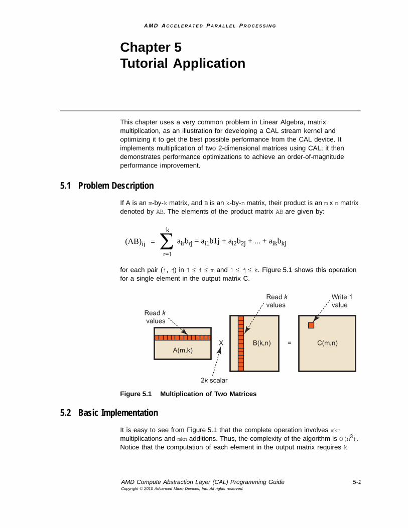
A M D A C C E L E R A T E D P A R A L L E L P R O C E S S I N G
AMD Compute Abstraction Layer (CAL) Programming Guide 5-1Copyright © 2010 Advanced Micro Devices, Inc. All rights reserved.
Chapter 5Tutorial Application
This chapter uses a very common problem in Linear Algebra, matrix multiplication, as an illustration for developing a CAL stream kernel and optimizing it to get the best possible performance from the CAL device. It implements multiplication of two 2-dimensional matrices using CAL; it then demonstrates performance optimizations to achieve an order-of-magnitude performance improvement.
5.1 Problem DescriptionIf A is an m-by-k matrix, and B is an k-by-n matrix, their product is an m x n matrix denoted by AB. The elements of the product matrix AB are given by:
for each pair (i, j) in 1 ≤ i ≤ m and 1 ≤ j ≤ k. Figure 5.1 shows this operation for a single element in the output matrix C.
Figure 5.1 Multiplication of Two Matrices
5.2 Basic ImplementationIt is easy to see from Figure 5.1 that the complete operation involves mkn multiplications and mkn additions. Thus, the complexity of the algorithm is O(n3). Notice that the computation of each element in the output matrix requires k
(AB)ij Σ airbrj = ai1b1j + ai2b2j + ... + aikbkj=k
r=1
X =
Read kvalues
Read kvalues
Write 1value
2k scalar
A(m,k)B(k,n) C(m,n)
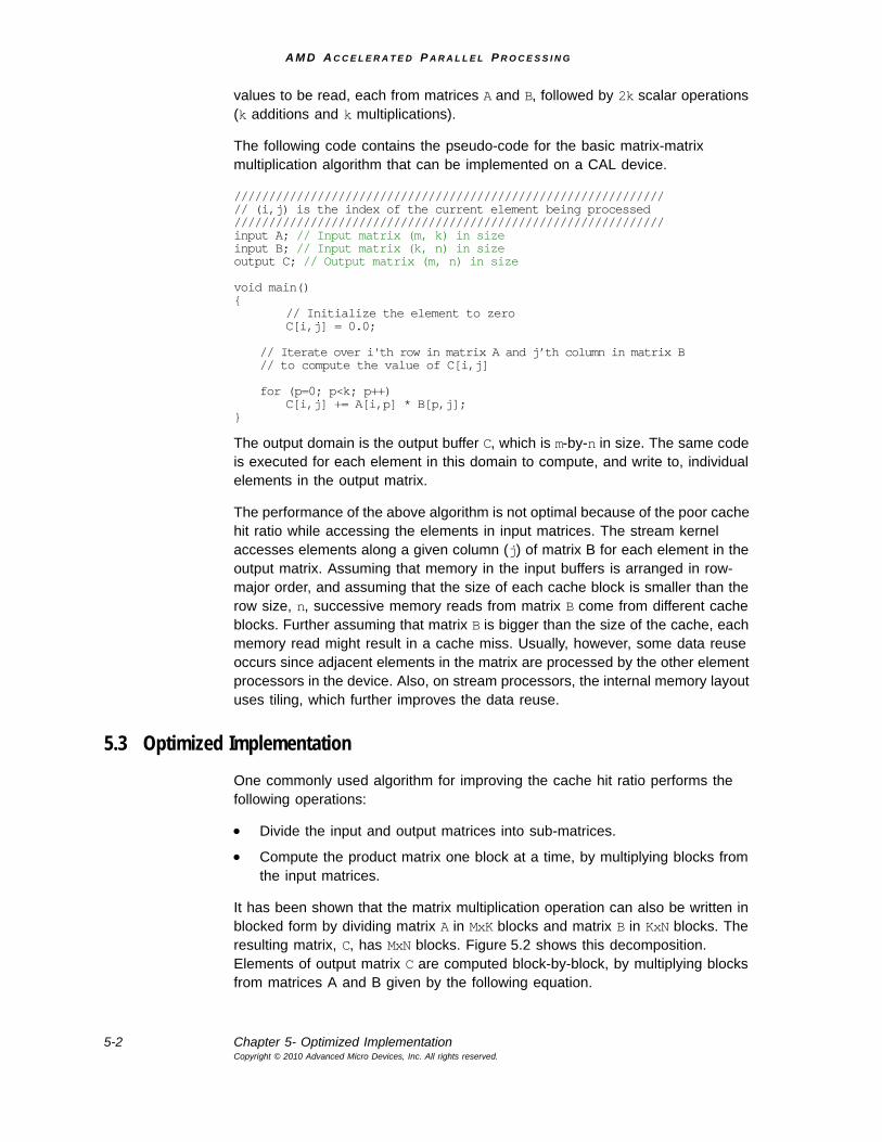
A M D A C C E L E R A T E D P A R A L L E L P R O C E S S I N G
5-2 Chapter 5- Optimized ImplementationCopyright © 2010 Advanced Micro Devices, Inc. All rights reserved.
values to be read, each from matrices A and B, followed by 2k scalar operations (k additions and k multiplications).
The following code contains the pseudo-code for the basic matrix-matrix multiplication algorithm that can be implemented on a CAL device.
//////////////////////////////////////////////////////////////// (i,j) is the index of the current element being processed//////////////////////////////////////////////////////////////input A; // Input matrix (m, k) in sizeinput B; // Input matrix (k, n) in sizeoutput C; // Output matrix (m, n) in size
void main(){
// Initialize the element to zeroC[i,j] = 0.0;
// Iterate over i'th row in matrix A and j’th column in matrix B// to compute the value of C[i,j]
for (p=0; p<k; p++)C[i,j] += A[i,p] * B[p,j];
}
The output domain is the output buffer C, which is m-by-n in size. The same code is executed for each element in this domain to compute, and write to, individual elements in the output matrix.
The performance of the above algorithm is not optimal because of the poor cache hit ratio while accessing the elements in input matrices. The stream kernel accesses elements along a given column (j) of matrix B for each element in the output matrix. Assuming that memory in the input buffers is arranged in row-major order, and assuming that the size of each cache block is smaller than the row size, n, successive memory reads from matrix B come from different cache blocks. Further assuming that matrix B is bigger than the size of the cache, each memory read might result in a cache miss. Usually, however, some data reuse occurs since adjacent elements in the matrix are processed by the other element processors in the device. Also, on stream processors, the internal memory layout uses tiling, which further improves the data reuse.
5.3 Optimized ImplementationOne commonly used algorithm for improving the cache hit ratio performs the following operations:
• Divide the input and output matrices into sub-matrices.
• Compute the product matrix one block at a time, by multiplying blocks from the input matrices.
It has been shown that the matrix multiplication operation can also be written in blocked form by dividing matrix A in MxK blocks and matrix B in KxN blocks. The resulting matrix, C, has MxN blocks. Figure 5.2 shows this decomposition. Elements of output matrix C are computed block-by-block, by multiplying blocks from matrices A and B given by the following equation.
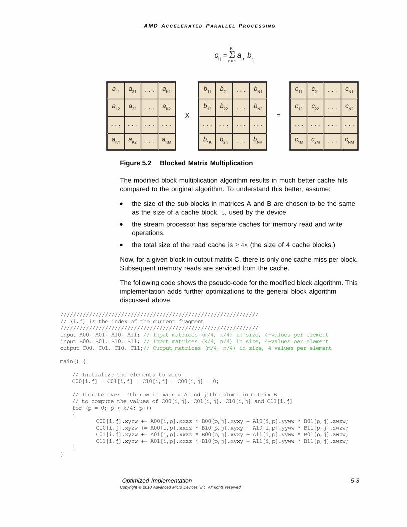
A M D A C C E L E R A T E D P A R A L L E L P R O C E S S I N G
Optimized Implementation 5-3Copyright © 2010 Advanced Micro Devices, Inc. All rights reserved.
Figure 5.2 Blocked Matrix Multiplication
The modified block multiplication algorithm results in much better cache hits compared to the original algorithm. To understand this better, assume:
• the size of the sub-blocks in matrices A and B are chosen to be the same as the size of a cache block, s, used by the device
• the stream processor has separate caches for memory read and write operations,
• the total size of the read cache is ≥ 4s (the size of 4 cache blocks.)
Now, for a given block in output matrix C, there is only one cache miss per block. Subsequent memory reads are serviced from the cache.
The following code shows the pseudo-code for the modified block algorithm. This implementation adds further optimizations to the general block algorithm discussed above.
//////////////////////////////////////////////////////////////// (i,j) is the index of the current fragment//////////////////////////////////////////////////////////////input A00, A01, A10, A11; // Input matrices (m/4, k/4) in size, 4-values per elementinput B00, B01, B10, B11; // Input matrices (k/4, n/4) in size, 4-values per elementoutput C00, C01, C10, C11;// Output matrices (m/4, n/4) in size, 4-values per element
main() {
// Initialize the elements to zeroC00[i,j] = C01[i,j] = C10[i,j] = C00[i,j] = 0;
// Iterate over i'th row in matrix A and j’th column in matrix B// to compute the values of C00[i,j], C01[i,j], C10[i,j] and C11[i,j]for (p = 0; p < k/4; p++){
C00[i,j].xyzw += A00[i,p].xxzz * B00[p,j].xyxy + A10[i,p].yyww * B01[p,j].zwzw;C10[i,j].xyzw += A00[i,p].xxzz * B10[p,j].xyxy + A10[i,p].yyww * B11[p,j].zwzw;C01[i,j].xyzw += A01[i,p].xxzz * B00[p,j].xyxy + A11[i,p].yyww * B01[p,j].zwzw;C11[i,j].xyzw += A01[i,p].xxzz * B10[p,j].xyxy + A11[i,p].yyww * B11[p,j].zwzw;
}}
a11 a21 aK1
aK2a22a12
aKMaK2aK1
. . .
. . .
. . .. . .. . . . . .
. . .
b11 b21 bN1
bN2b22b12
bNKb2Kb1K
. . .
. . .
. . .. . .. . . . . .
. . .
c11 c21 cN1
cN2c22c12
cNMc2Mc1M
. . .
. . .
. . .. . .. . . . . .
. . .
X =
ci j = ai r br j
K
r = 1
A M D A C C E L E R A T E D P A R A L L E L P R O C E S S I N G
5-4 Chapter 5- Optimized ImplementationCopyright © 2010 Advanced Micro Devices, Inc. All rights reserved.
Note the following important points about the stream kernel in the above implementation:
• It processes all four blocks in output matrix C within the computational loop.
• It leverages the superscalar floating units available on the SIMD engine by packing the input matrices so that each element in the input and output matrices contains four values.
– The size of each matrix block now becomes 1/16th of the original matrix size (divided into 4 blocks with 4 values per element).
– The number of output values computed and written by each stream kernel is 16.
– To get the correct result, the input data must be preprocessed so that each four-component element in the input matrices contain a 2x2 micro-tile of data values from the original matrix (see Figure 5.3).
– The matrix multiplication done inside the loop computes a 2x2 micro-tile in the output matrix and writes it as a four-component element. Thus, the output data also must be post-processed to re-arrange the data in the correct order.
Figure 5.3 Micro-Tiled Blocked Matrix Multiplication
If the conditions specified earlier in this section hold true, the above algorithm gives near optimal performance with close to 100% cache hit ratio. However, in actual implementations, the total working set for each block multiplication might not fit in the cache. The reads cause cache misses, reducing the performance of the operation.
Note that the exact blocked decomposition scheme (values for M, N and K mentioned above) used in the implementation depends on the capabilities of the underlying stream processor architecture. For a stream processor that has a maximum of eight output buffers, the maximum number of tiles in the decomposed matrix is limited to 8x1. The best-performing algorithm that ships with the CAL SDK uses M = 8, K = 4, N = 8. With the four-component packing, it performs multiplication of 8x1 four-component blocks for matrix A with 4x1 four-component blocks of matrix B to compute 8x1 four-component blocks of matrix C.
X =
a11 a21
a22a12
b11 b21
b22b12
c11 c21
c22c12
A M D A C C E L E R A T E D P A R A L L E L P R O C E S S I N G
AMD Compute Abstraction Layer (CAL) Programming Guide 6-1Copyright © 2010 Advanced Micro Devices, Inc. All rights reserved.
Chapter 6AMD CAL/Direct3D Interoperability
CAL features extensions providing interoperability with Direct3D 9 and Direct3D 10 on Windows Vista®. When interoperability is used, Direct3D memory allocations can be used as inputs to, or outputs of, CAL kernels. The application must synchronize accesses of the memory from the CAL and Direct3D APIs. This can be done by using calCtxIsEventDone and Direct3D queries.
To use the interoperability, first the appropriate calD3DAssociate call must be made. This associates a CAL device to the corresponding Direct3D device. Once the devices have been associated, use the calD3DMap functions to create a CALresource from a Direct3D object. The CALresources returned from these calls can be used like any other CAL resource. When the application is finished using the allocation, it can be freed with the standard calResFree call. The CALresource must be freed before the Direct3D object is released.
Section A.4.2, “Interoperability Extensions,” page A-22, provides details of the interoperability extensions.
A M D A C C E L E R A T E D P A R A L L E L P R O C E S S I N G
6-2 Chapter 6- Copyright © 2010 Advanced Micro Devices, Inc. All rights reserved.
A M D A C C E L E R A T E D P A R A L L E L P R O C E S S I N G
AMD Compute Abstraction Layer (CAL) Programming Guide 7-1Copyright © 2010 Advanced Micro Devices, Inc. All rights reserved.
Chapter 7Advanced Topics
This chapter covers some advanced topics for developers who want to add new features to CAL applications or use specific features in certain AMD processors.
7.1 Thread-SafetyMost computationally expensive applications use multiple CPU threads to improve application performance and/or responsiveness. This typically is done by using techniques like task partitioning and pipelining in conjunction with asynchronous parallel execution on multiple processing units. In general, the CAL API is not re-entrant; that is, if more than one thread is active within a CAL function, the function invocation is not thread-safe. To invoke the same CAL function from multiple threads, the application must serialize access to these functions using synchronization primitives such as locks. The calCtx* functions are the exception to this rule, as long as objects tieed to CAL functions are not destroyed or manipulated in a separate thread. Such a model permits actions on a given context to be completely asynchronous from those on other contexts by using separate threads. The creation and destruction of resources, modules, functions, devices, contexts, etc. must be managed properly by the application in order to prevent unexpected results.
When using the CAL API in multi-threaded applications:
• CAL Compiler routines are not thread-safe. Applications invoking compiler routines from multiple threads must do proper synchronization to serialize the invocation of these routines.
• CAL Runtime routines that are either context-specific or device-specific are thread-safe. All other CAL runtime routines are not thread-safe.
• If the same context is shared among multiple threads, invocation of the calCtx* functions must be serialized by the application.
7.2 Multiple Stream ProcessorsModern PC architecture allows deploying multiple PCIe devices on a system. CAL allows applications to improve performance by leveraging the computational power of multiple stream processor units that might be available on the system. Multiple devices can run in parallel by using separate threads managing each of the stream processors using one context per device1. CAL detects all available stream processors on the system during initialization in calInit. Subsequently, applications can query the number of devices on the system using
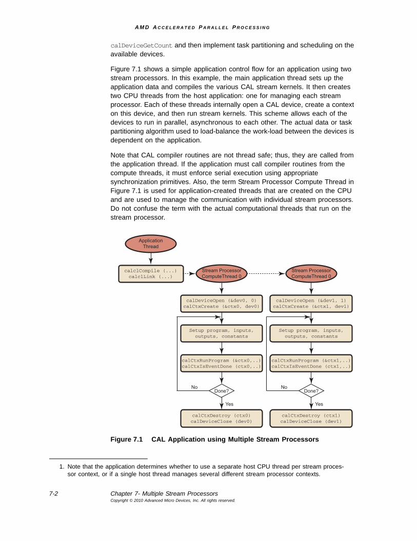
A M D A C C E L E R A T E D P A R A L L E L P R O C E S S I N G
7-2 Chapter 7- Multiple Stream ProcessorsCopyright © 2010 Advanced Micro Devices, Inc. All rights reserved.
calDeviceGetCount and then implement task partitioning and scheduling on the available devices.
Figure 7.1 shows a simple application control flow for an application using two stream processors. In this example, the main application thread sets up the application data and compiles the various CAL stream kernels. It then creates two CPU threads from the host application: one for managing each stream processor. Each of these threads internally open a CAL device, create a context on this device, and then run stream kernels. This scheme allows each of the devices to run in parallel, asynchronous to each other. The actual data or task partitioning algorithm used to load-balance the work-load between the devices is dependent on the application.
Note that CAL compiler routines are not thread safe; thus, they are called from the application thread. If the application must call compiler routines from the compute threads, it must enforce serial execution using appropriate synchronization primitives. Also, the term Stream Processor Compute Thread in Figure 7.1 is used for application-created threads that are created on the CPU and are used to manage the communication with individual stream processors. Do not confuse the term with the actual computational threads that run on the stream processor.
Figure 7.1 CAL Application using Multiple Stream Processors
1. Note that the application determines whether to use a separate host CPU thread per stream proces-sor context, or if a single host thread manages several different stream processor contexts.
ApplicationThread
calclCompile (...)calclLink (...)
Stream ProcessorComputeThread 0
calDeviceOpen (&dev0, 0)calCtxCreate (&ctx0, dev0)
Setup program, inputs,outputs, constants
calCtxRunProgram (&ctx0,..)calCtxIsEventDone (ctx0,..)
calCtxDestroy (ctx0)calDeviceClose (dev0)
Done?
Yes
No
Stream ProcessorComputeThread 0
calDeviceOpen (&dev1, 1)calCtxCreate (&ctx1, dev1)
Setup program, inputs,outputs, constants
calCtxRunProgram (&ctx1,..)calCtxIsEventDone (ctx1,..)
calCtxDestroy (ctx1)calDeviceClose (dev1)
Done?
Yes
No
A M D A C C E L E R A T E D P A R A L L E L P R O C E S S I N G
Unordered Access Views (UAVs) in CAL 7-3Copyright © 2010 Advanced Micro Devices, Inc. All rights reserved.
7.3 Unordered Access Views (UAVs) in CALUnordered Access Views (UAVs) let applications read from, and write to, arbitrary locations in input buffers and output buffers, respectively. To use UAVs, the application must perform two modifications to a CAL application:
• To provide linear access to the UAV, use CAL_RESALLOC_GLOBAL_BUFFER to request the CAL runtime to allocate global buffers when allocating resources. If the UAV is not linear, no flag is needed for the allocation.
• Specify the output (input) name for the output (input) value to be written to (read from) the UAV (input) buffer.
There can be up-to eight UAVs used in a kernel (for the Evergreen family of GPUs; for the R7XX series, it is one), so CALnames would be uav0 to uav7.
7.3.1 UAV Allocation
A UAV can be allocated using the CAL runtime API by passing the CAL_RESALLOC_GLOBAL_BUFFER flag while allocating CAL resources. UAVs can be allocated as local (stream processor) and as remote (system) memory, as shown in the following code example.
CALresource remoteUAVRes = 0, localUAVRes = 0;CALformat format = CAL_FORMAT_FLOAT32_1;CALresallocflags flag = CAL_RESALLOC_GLOBAL_BUFFER;// Allocate 2D UAV remote resourcecalResAllocRemote2D(&remoteUAVRes, &device, 1, width, height,format, flag);if(!remoteUAVRes)
{fprintf(stdout, "UAV remote resource not available on device \n");return -1;
}// Allocate 2D UAV local resourcecalResAllocLocal2D(&localUAVRes, device, width, height, format, flag);if(!localUAVRes)
{fprintf(stdout, "UAV local resource not available on device \n");return -1;
}
The rest of the mechanism for binding the resources to CPU pointers, CAL context-specific memory handles, and stream kernel inputs and outputs remain the same as normal CAL data buffers.
7.3.2 Accessing UAVs From a Stream Kernel
The following AMD IL kernel reads data from an input buffer and uses this value as an address to write into the UAV output buffer. The value written is the position in the domain corresponding to the current instance of the stream kernel.
"il_ps_2_0\n"// Declarations for inputs and outputs"dcl_input_position_interp(linear_noperspective) v0\n""dcl_cb cb0[1]\n""dcl_resource_id(0)_type(2d,unnorm)_fmtx(float)_fmty(float)_fmtz(float)_fmtw(float)\n"
A M D A C C E L E R A T E D P A R A L L E L P R O C E S S I N G
7-4 Chapter 7- Using the Global Buffer in CALCopyright © 2010 Advanced Micro Devices, Inc. All rights reserved.
"dcl_raw_uav_id(0)\n"// Read from (x,y)"sample_resource(0)_sampler(0) r0, vWinCoord0.xyxx\n"// Compute output address by computing offset in global buffer"mad r0.x, r0.y, cb0[0].x, r0.x\n"// Convert address from float to integer"ftoi r1.x, r0.x\n"// Convert the address from index into 2-dword aligned addresses// since we are writing to 32bit components to the uav memory"dcl_literal l0, 3, 3, 3, 3\n""ishl r1.x, r1.x, l0.x\n" "uav_raw_store_id(0) mem0.xy, r1.x, vWinCoord0.xy\n""ret_dyn\n""end\n";
Note that in this code:
• The raw_store function uses the mem register type to specify how many components to write.
• The address passed to uav_raw_store_id and the other UAV functions must be dword-aligned, with the exception of the arena uav functions.
7.4 Using the Global Buffer in CALThe global buffer lets applications read from, and write to, arbitrary locations in input buffers and output buffers, respectively (see the scatter_IL and gather_IL sample programs in the $(CALROOT)/samples/languages/IL directory). To use global buffers, the application must perform two main modifications to a CAL application:
• request the CAL runtime to allocate global buffers when allocating resources using CAL_RESALLOC_GLOBAL_BUFFER, and
• specify the output (input) position for the output (input) value to be written to (read from) the global output (input) buffer.
7.4.1 Global Buffer Allocation
A global buffer can be allocated using the CAL runtime API: simply pass the CAL_RESALLOC_GLOBAL_BUFFER flag while allocating CAL resources. Global buffers can be allocated as local (stream processor) and as remote (system) memory. The following code shows this:
CALresource remoteGlobalRes = 0, localGlobalRes = 0;CALformat format = CAL_FORMAT_FLOAT32_1;CALresallocflags flag = CAL_RESALLOC_GLOBAL_BUFFER;
// Allocate 2D global remote resourcecalResAllocRemote2D(&remoteGlobalRes, &device, 1, width, height,
format, flag);if(!remoteGlobalRes){
fprintf(stdout, "Global remote resource not available on device \n");return -1;
}
A M D A C C E L E R A T E D P A R A L L E L P R O C E S S I N G
Using the Global Buffer in CAL 7-5Copyright © 2010 Advanced Micro Devices, Inc. All rights reserved.
// Allocate 2D global local resourcecalResAllocLocal2D(&localGlobalRes, device, width, height, format, flag);if(!localGlobalRes){
fprintf(stdout, "Global local resource not available on device \n");return -1;
}
The rest of the mechanism for binding the resources to CPU pointers, CAL context-specific memory handles, and stream kernel inputs and outputs remain the same as normal CAL data buffers.
Note: Global (Linear) buffers are always padded to a 64-element bound-ary; however, the memexport instruction is not constrained by this, and the program can write into the pad area. During mapping, when copying from local to remote storage, data written to the pad area is not copied (it is lost).
The hardware output paths are different when a buffer is attached as an export buffer rather than an output buffer.
Ensure that the global buffer has a width that is a multiple of 64 ele-ments.
When entering a width that is not multiple of 64 and using the global buffer, calResAllocLocal2D returns a warning. Users also can query the error message for this warning.
7.4.2 Accessing the Global Buffer From a Stream Kernel
The following AMD IL kernel reads data from an input buffer and uses this value as an address to write into the global output buffer. The value written is the position in the domain corresponding to the current instance of the stream kernel.
"il_ps_2_0\n"
// Declarations for inputs and outputs"dcl_input_position_interp(linear_noperspective) v0\n""dcl_output_generic o0\n""dcl_cb cb0[1]\n""dcl_resource_id(0)_type(2d,unnorm)_fmtx(float)_fmty(float)_fmtz(float)_fmtw(float)\n"
// Read from (x,y)"sample_resource(0)_sampler(0) r0, vWinCoord0.xyxx\n"
// Compute output address by computing offset in global buffer"mad r0.x, r0.y, cb0[0].x, r0.x\n"
// Convert address from float to integer"ftoi r1.x, r0.x\n"
// Output current position to output address in the global buffer"mov g[r1.x], vWinCoord0.xy\n"
"ret_dyn\n""end\n";
A M D A C C E L E R A T E D P A R A L L E L P R O C E S S I N G
7-6 Chapter 7- Double-Precision ArithmeticCopyright © 2010 Advanced Micro Devices, Inc. All rights reserved.
Note that in this code:
• The global buffer is accessed using the global memory register, g[address].
• The address passed to the global buffer must be a scalar integer value. The address can be a literal constant (for example, g[2]) or a temporary register (r1.x in the above example).
7.5 Double-Precision ArithmeticDouble-precision arithmetic allows applications to minimize computational inaccuracies that can result due to the use of single-precision arithmetic. Support for double-precision is a crucial factor for certain applications, including engineering analysis, scientific simulations, etc. The AMD IL provides special instructions that allow applications to perform computations using 64-bit double-precision in the stream processor (see the DoublePrecision tutorial program, located in $CALROOT\samples\tutorial\). Typically, double-precision instructions are simply specified by prefixing the single-precision floating point instructions with d (for example, the double-precision counterpart for the add instruction is dadd). For a complete reference on AMD IL syntax, as well as a list of double-precision instructions, see the AMD Compute Abstraction Layer (CAL) Intermediate Language (IL) Reference Manual.
Assume temporary 32-bit registers. To represent 64-bit arithmetic values, two register components are used. The f2d and d2f instructions can convert from single-precision to double-precision and back. The following AMD IL kernel snippet converts two 32-bit floating values to 64-bit double-precision and multiplies the values using 64-bit instructions. (Note that using conversion functions that are not in the range specified in Section 6.3 of the AMD Compute Abstraction Layer (CAL) Intermediate Language (IL) Reference Manual can result in the degradation of accuracy.)
//Convert to double-precision values"f2d r1.xy, r0.x\n""f2d r1.zw, r0.y\n"
// Perform double-precision multiplication"dmul r2.zw, r1.zw, r1.xy\n"
The dmul instruction performs a single double-precision multiplication using two components of the source and destination registers. Note that the following operation for double-precision multiplication also performs a single scalar multiplication operation and not a vector multiplication, as might be expected.
// The following operation is the same as dmul r2.xy, r1.xy, r1.xydmul r2, r1, r1
A M D A C C E L E R A T E D P A R A L L E L P R O C E S S I N G
AMD Compute Abstraction Layer (CAL) Programming Guide A-1Copyright © 2010 Advanced Micro Devices, Inc. All rights reserved.
Appendix A AMD CAL API Specification 1.4
The AMD Compute Abstraction Layer (CAL) provides a forward-compatible, interface to the high-performance, floating-point, parallel processor arrays found in AMD GPUs and in CPUs.
The CAL API is designed so that:
• the computational model is processor independent.
• the user can easily switch from directing a computation from stream processor to CPU or vice versa.
• it permits a dynamic load balancer to be written on top of CAL.
• CAL is a lightweight implementation that facilitates a compute platform such as OpenCL to be developed on top of it.
CAL is supported on R6xx and newer generations of AMD GPUs and all CPU processors. It runs on both 32-bit and 64-bit versions of Windows® XP, Windows Vista®, and Linux®.
A.1 Programming ModelThe CAL application executes on the CPU, driving one or more stream processors. A stream processor is connected to two types of memory: local (stream processor) and remote (system). Contexts on a stream processor can read and write to both memory pools. Context reads and writes to local memory are faster than those to remote memory. The master process also can read and write to local and remote memory. Typically, the master process has higher read and write speeds to the remote (system) memory of the stream processors. The master process submits commands or jobs for execution on the multiple contexts of a stream processor. The master process also can query the context for the status of the completion of these tasks. Figure A.1 illustrates a CAL system.
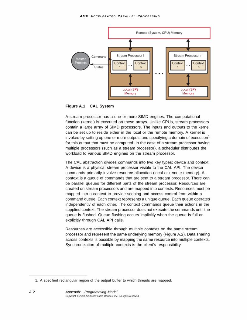
A M D A C C E L E R A T E D P A R A L L E L P R O C E S S I N G
A-2 Appendix - Programming ModelCopyright © 2010 Advanced Micro Devices, Inc. All rights reserved.
Figure A.1 CAL System
A stream processor has a one or more SIMD engines. The computational function (kernel) is executed on these arrays. Unlike CPUs, stream processors contain a large array of SIMD processors. The inputs and outputs to the kernel can be set up to reside either in the local or the remote memory. A kernel is invoked by setting up one or more outputs and specifying a domain of execution1 for this output that must be computed. In the case of a stream processor having multiple processors (such as a stream processor), a scheduler distributes the workload to various SIMD engines on the stream processor.
The CAL abstraction divides commands into two key types: device and context. A device is a physical stream processor visible to the CAL API. The device commands primarily involve resource allocation (local or remote memory). A context is a queue of commands that are sent to a stream processor. There can be parallel queues for different parts of the stream processor. Resources are created on stream processors and are mapped into contexts. Resources must be mapped into a context to provide scoping and access control from within a command queue. Each context represents a unique queue. Each queue operates independently of each other. The context commands queue their actions in the supplied context. The stream processor does not execute the commands until the queue is flushed. Queue flushing occurs implicitly when the queue is full or explicitly through CAL API calls.
Resources are accessible through multiple contexts on the same stream processor and represent the same underlying memory (Figure A.2). Data sharing across contexts is possible by mapping the same resource into multiple contexts. Synchronization of multiple contexts is the client’s responsibility.
1. A specified rectangular region of the output buffer to which threads are mapped.
Remote (System, CPU) Memory
MasterProcess
Local (SP)Memory
Stream Processor1
Context1
ContextnStatus
Command
Local (SP)Memory
Stream Processor n
Context1
Contextn
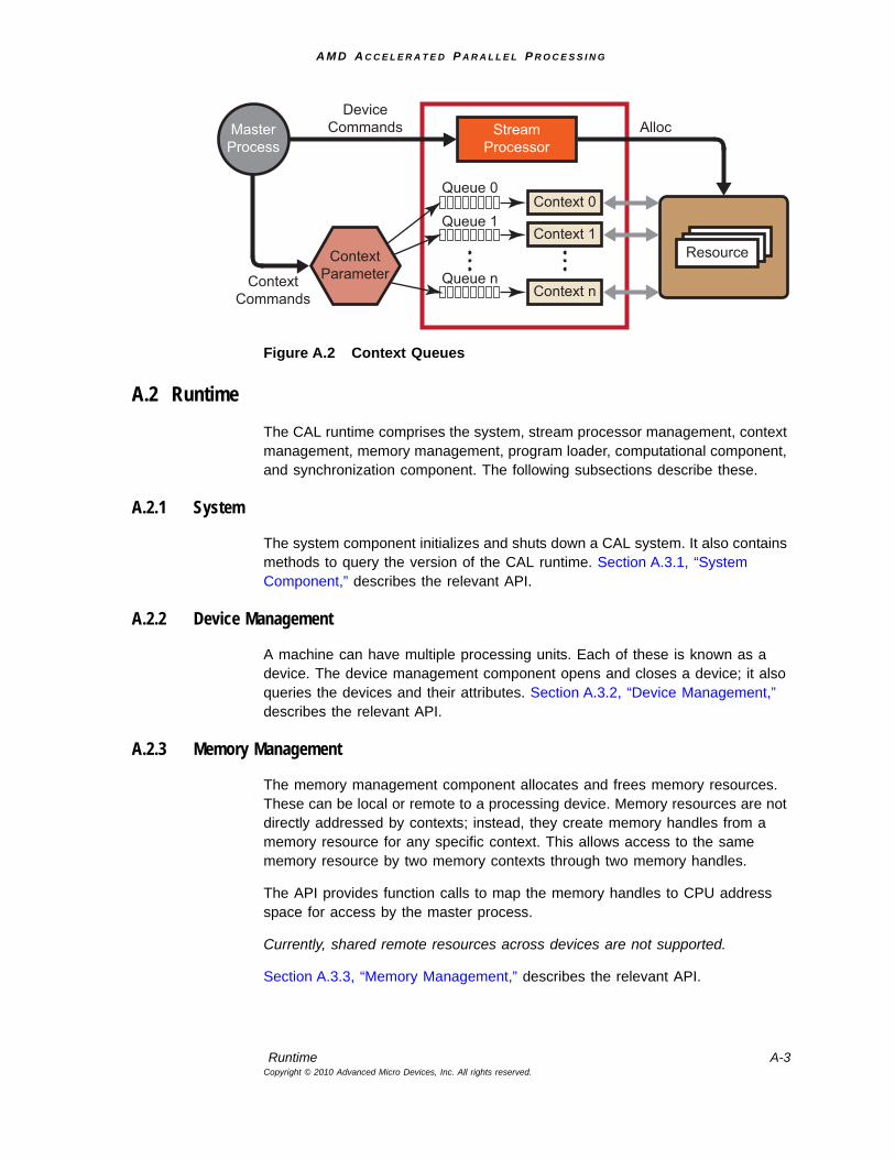
A M D A C C E L E R A T E D P A R A L L E L P R O C E S S I N G
Runtime A-3Copyright © 2010 Advanced Micro Devices, Inc. All rights reserved.
Figure A.2 Context Queues
A.2 RuntimeThe CAL runtime comprises the system, stream processor management, context management, memory management, program loader, computational component, and synchronization component. The following subsections describe these.
A.2.1 System
The system component initializes and shuts down a CAL system. It also contains methods to query the version of the CAL runtime. Section A.3.1, “System Component,” describes the relevant API.
A.2.2 Device Management
A machine can have multiple processing units. Each of these is known as a device. The device management component opens and closes a device; it also queries the devices and their attributes. Section A.3.2, “Device Management,” describes the relevant API.
A.2.3 Memory Management
The memory management component allocates and frees memory resources. These can be local or remote to a processing device. Memory resources are not directly addressed by contexts; instead, they create memory handles from a memory resource for any specific context. This allows access to the same memory resource by two memory contexts through two memory handles.
The API provides function calls to map the memory handles to CPU address space for access by the master process.
Currently, shared remote resources across devices are not supported.
Section A.3.3, “Memory Management,” describes the relevant API.
MasterProcess
DeviceCommands
ContextCommands
Alloc
Resource
StreamProcessor
Queue 0
Queue 1
Queue n
Context 0
Context 1
Context n
ContextParameter
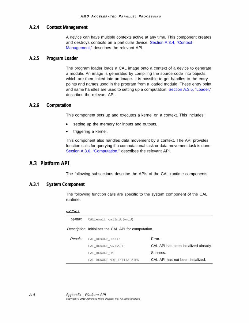
A M D A C C E L E R A T E D P A R A L L E L P R O C E S S I N G
A-4 Appendix - Platform APICopyright © 2010 Advanced Micro Devices, Inc. All rights reserved.
A.2.4 Context Management
A device can have multiple contexts active at any time. This component creates and destroys contexts on a particular device. Section A.3.4, “Context Management,” describes the relevant API.
A.2.5 Program Loader
The program loader loads a CAL image onto a context of a device to generate a module. An image is generated by compiling the source code into objects, which are then linked into an image. It is possible to get handles to the entry points and names used in the program from a loaded module. These entry point and name handles are used to setting up a computation. Section A.3.5, “Loader,” describes the relevant API.
A.2.6 Computation
This component sets up and executes a kernel on a context. This includes:
• setting up the memory for inputs and outputs,
• triggering a kernel.
This component also handles data movement by a context. The API provides function calls for querying if a computational task or data movement task is done. Section A.3.6, “Computation,” describes the relevant API.
A.3 Platform APIThe following subsections describe the APIs of the CAL runtime components.
A.3.1 System Component
The following function calls are specific to the system component of the CAL runtime.
calInit
Syntax CALresult calInit(void)
Description Initializes the CAL API for computation.
Results CAL_RESULT_ERROR Error.
CAL_RESULT_ALREADY CAL API has been initialized already.
CAL_RESULT_OK Success.
CAL_RESULT_NOT_INITIALZIED CAL API has not been initialized.
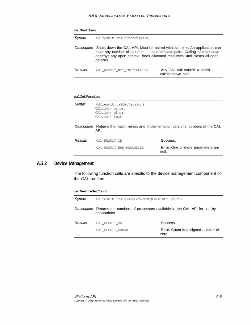
A M D A C C E L E R A T E D P A R A L L E L P R O C E S S I N G
Platform API A-5Copyright © 2010 Advanced Micro Devices, Inc. All rights reserved.
A.3.2 Device Management
The following function calls are specific to the device management component of the CAL runtime.
calShutdown
Syntax CALresult calShutdown(void)
Description Shuts down the CAL API. Must be paired with calInit. An application can have any number of calInit - calShutdown pairs. Calling calShutdown destroys any open context, frees allocated resources, and closes all open devices.
Results CAL_RESULT_NOT_INITIALZIED Any CAL call outside a calInit - calShutdown pair.
calGetVersion
Syntax CALresult calGetVersion(CALuint* major, CALuint* minor, CALuint* imp)
Description Returns the major, minor, and implementation versions numbers of the CAL API.
Results CAL_RESULT_OK Success.
CAL_RESULT_BAD_PARAMETER Error. One or more parameters are null.
calDeviceGetCount
Syntax CALresult calDeviceGetCount(CALuint* count)
Description Returns the numbers of processors available to the CAL API for use by applications.
Results CAL_RESULT_OK Success.
CAL_RESULT_ERROR Error. Count is assigned a value of zero.
A M D A C C E L E R A T E D P A R A L L E L P R O C E S S I N G
A-6 Appendix - Platform APICopyright © 2010 Advanced Micro Devices, Inc. All rights reserved.
calDeviceGetAttribs
Syntax CALresult calDeviceGetAttribs (CALdeviceattribs* attribs, CALuint ordinal)
Description Returns device-specific information about the processor in attribs. The device is specified by ordinal, which must be in the range of zero to the number of devices returned by calDeviceGetCount minus one. The device does not have to be open to obtain information about it. The struct_size field of the CALdeviceattribs structure must be filled out prior to calling calDeviceGetInfo. (See Section A.5.2, “Structures,” page A-31, for details on the CALdeviceattribs structure.)
Results CAL_RESULT_OK Success, and attribs contains information about the device.
CAL_RESULT_INVALID_PARAMETER Error if ordinal is not a valid device number.
CAL_RESULT_ERROR Error if information about the device cannot be obtained.
On error, the contents of attribs is undefined.
calDeviceOpen
Syntax CALresult calDeviceOpen(CALdevice* dev, CALuint ordinal)
Description Opens a device indexed by ordinal. A device must be closed before it can be opened again in the same application. Always pair this call with calDeviceClose.
Results CAL_RESULT_OK Success, and dev is a valid handle to the device.
CAL_RESULT_INVALID_PARAMETER Error if ordinal is not a valid device number.
CAL_RESULT_ERROR Error if information about the device cannot be opened.
On error, dev is zero.
A M D A C C E L E R A T E D P A R A L L E L P R O C E S S I N G
Platform API A-7Copyright © 2010 Advanced Micro Devices, Inc. All rights reserved.
calDeviceGetStatus
Syntax CALresult calDeviceGetStatus (CALdevicestatus* status, CALdevice dev)
Description Returns the current status of an open device.
Results CAL_RESULT_OK Success, and dev is a valid handle to the device.
CAL_RESULT_INVALID_PARAMETER Error if ordinal is not a valid device number.
CAL_RESULT_ERROR Error if information about the device cannot be opened.
On error, dev is zero.
calDeviceClose
Syntax CALresult calDeviceClose(CALdevice dev)
Description Closes a device specified by the dev handle. When a device is closed, all contexts created on the device are destroyed, and all resources on the device are freed. Always pair this call with calDeviceOpen.
Results CAL_RESULT_OK Success: dev is a valid handle to the device.
CAL_RESULT_ERROR The overall state is assumed to be as if calDeviceClose was never called.
A M D A C C E L E R A T E D P A R A L L E L P R O C E S S I N G
A-8 Appendix - Platform APICopyright © 2010 Advanced Micro Devices, Inc. All rights reserved.
A.3.3 Memory Management
The following function calls are specific to the memory management component of the CAL runtime.
calResAllocLocal2D
Syntax CALresult calResAllocLocal2D(CALresource* res,CALdevice device,CALuint width,CALuint height,CALformat format,CALuint flags)
Description Allocates memory local to a stream processor. The device specifies the stream processor to allocate the memory. This memory is structured as a two-dimensional region of width and height with a format. The maximum dimensions are available through the calDeviceGetInfo function.The flags parameter is used to specify a basic level of use for the memory. For local memory, the value must be zero unless the memory is used for memory export. If the memory is used for memory export, then flags must be CAL_RESALLOC_GLOBAL_BUFFER.
Results CAL_RESULT_OK Success, and res is a handle to the memory resource.
CAL_RESULT_BAD_HANDLE Error if dev is not a valid device.
CAL_RESULT_ERROR Error if the memory can not be allocated.
On error, res is zero.
A M D A C C E L E R A T E D P A R A L L E L P R O C E S S I N G
Platform API A-9Copyright © 2010 Advanced Micro Devices, Inc. All rights reserved.
calResAllocRemote2D
Syntax CALresult calResAllocRemote2D(CALresource* res,CALdevice* sharedDevices,CALuint deviceCount,CALuint width,CALuint height,CALformat format,CALuint flags)
Description Allocates memory remote to deviceCount number of devices in the sharedDevices array. The memory is system memory, remote to all stream processors. This memory is structured as a two-dimensional region of width and height with a format. The maximum dimensions are available through the calDeviceGetInfo function. The flags parameter specifies a basic level of use for the memory. For remote memory, zero means the memory is allocated in uncached system memory, CAL_RESALLOC_CACHEABLE forces the memory to be CPU cachable.
One benefit of devices being able to write to remote (system) memory is performance. For example, with large computational kernels, it sometimes is faster for the stream processor contexts to write directly to remote memory than it is to do process them in two steps: stream processor context writing to local memory, and copying data from stream processor local memory to remote system memory.
Results CAL_RESULT_OK Success, and res is a handle to the memory resource.
CAL_RESULT_BAD_HANDLE Error if any device in sharedDevices is not valid.
CAL_RESULT_ERROR Error if the memory can not be allocated.
On error, res is zero.
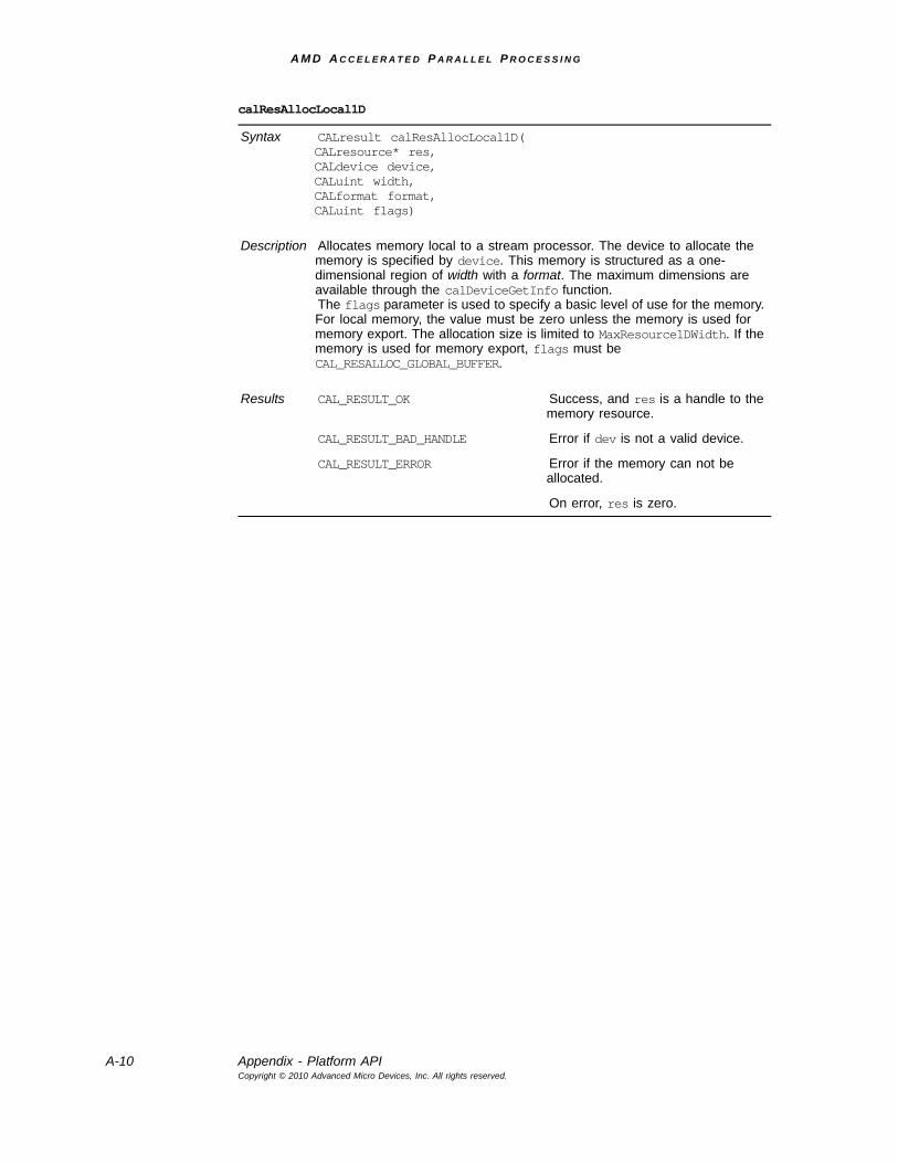
A M D A C C E L E R A T E D P A R A L L E L P R O C E S S I N G
A-10 Appendix - Platform APICopyright © 2010 Advanced Micro Devices, Inc. All rights reserved.
calResAllocLocal1D
Syntax CALresult calResAllocLocal1D(CALresource* res,CALdevice device,CALuint width,CALformat format,CALuint flags)
Description Allocates memory local to a stream processor. The device to allocate the memory is specified by device. This memory is structured as a one-dimensional region of width with a format. The maximum dimensions are available through the calDeviceGetInfo function.The flags parameter is used to specify a basic level of use for the memory. For local memory, the value must be zero unless the memory is used for memory export. The allocation size is limited to MaxResource1DWidth. If the memory is used for memory export, flags must be CAL_RESALLOC_GLOBAL_BUFFER.
Results CAL_RESULT_OK Success, and res is a handle to the memory resource.
CAL_RESULT_BAD_HANDLE Error if dev is not a valid device.
CAL_RESULT_ERROR Error if the memory can not be allocated.
On error, res is zero.

A M D A C C E L E R A T E D P A R A L L E L P R O C E S S I N G
Platform API A-11Copyright © 2010 Advanced Micro Devices, Inc. All rights reserved.
calResAllocRemote1D
Syntax CALresult calResAllocRemote1D(CALresource* res,CALdevice* sharedDevices,CALuint deviceCount,CALuint width,CALformat format,CALuint flags)
Description Allocates memory remote to deviceCount number of devices in the sharedDevices array. The memory is system memory (remote to all devices). It is structured as a one-dimensional region of width with a format. The maximum dimensions are available through the calDeviceGetInfo function.The flags parameter specifies a basic level of use for the memory. For remote memory, zero means the memory is allocated in uncached system memory, CAL_RESALLOC_CACHEABLE forces the memory to be CPU-cachable.One benefit of devices being able to write to remote (system) memory is performance. For example, with large computational kernels, it sometimes is faster for the stream processor contexts to write directly to remote memory than it is to do process them in two steps: stream processor context writing to local memory, and copying data from stream processor local memory to remote system memory. The flags parameter is used to specify a basic level of use for the memory. For remote memory, the value must be zero unless the memory is used for memory export. The allocation size is limited to MaxResource1DWidth. If the memory is used for memory export, flags must be CAL_RESALLOC_GLOBAL_BUFFER.
Results CAL_RESULT_OK Success, and res is a handle to the memory resource.
CAL_RESULT_BAD_HANDLE Error if any device in sharedDevices is not valid.
CAL_RESULT_ERROR Error if the memory can not be allocated.
On error, res is zero.
calResFree
Syntax CALresult calResFree(CALresource res)
Description Releases the memory resources as specified by handle res.
Results CAL_RESULT_OK Success.
CAL_RESULT_BAD_HANDLE Error if res is an invalid handle
CAL_RESULT_BUSY Error if the resource is in use by a context.
On error, the state is as if calResFree had never been called. Use calCtxReleaseMem to release a resource handle from a context.
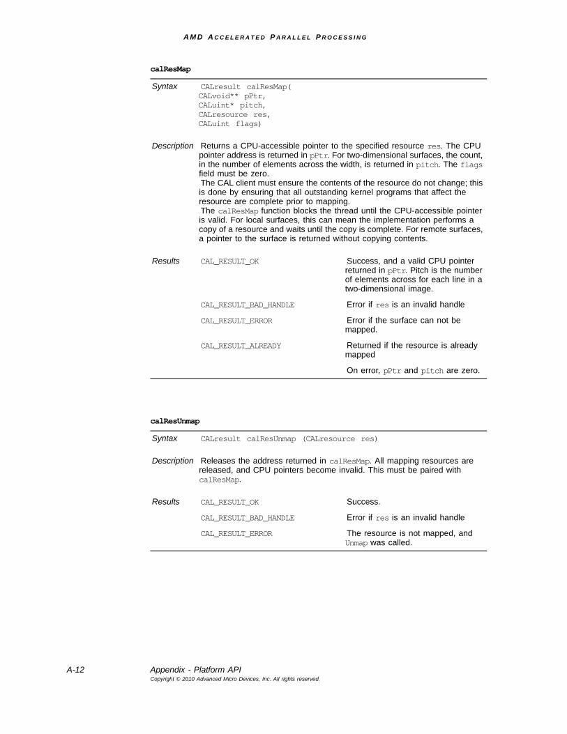
A M D A C C E L E R A T E D P A R A L L E L P R O C E S S I N G
A-12 Appendix - Platform APICopyright © 2010 Advanced Micro Devices, Inc. All rights reserved.
calResMap
Syntax CALresult calResMap(CALvoid** pPtr,CALuint* pitch,CALresource res,CALuint flags)
Description Returns a CPU-accessible pointer to the specified resource res. The CPU pointer address is returned in pPtr. For two-dimensional surfaces, the count, in the number of elements across the width, is returned in pitch. The flags field must be zero.The CAL client must ensure the contents of the resource do not change; this is done by ensuring that all outstanding kernel programs that affect the resource are complete prior to mapping.The calResMap function blocks the thread until the CPU-accessible pointer is valid. For local surfaces, this can mean the implementation performs a copy of a resource and waits until the copy is complete. For remote surfaces, a pointer to the surface is returned without copying contents.
Results CAL_RESULT_OK Success, and a valid CPU pointer returned in pPtr. Pitch is the number of elements across for each line in a two-dimensional image.
CAL_RESULT_BAD_HANDLE Error if res is an invalid handle
CAL_RESULT_ERROR Error if the surface can not be mapped.
CAL_RESULT_ALREADY Returned if the resource is already mapped
On error, pPtr and pitch are zero.
calResUnmap
Syntax CALresult calResUnmap (CALresource res)
Description Releases the address returned in calResMap. All mapping resources are released, and CPU pointers become invalid. This must be paired with calResMap.
Results CAL_RESULT_OK Success.
CAL_RESULT_BAD_HANDLE Error if res is an invalid handle
CAL_RESULT_ERROR The resource is not mapped, and Unmap was called.
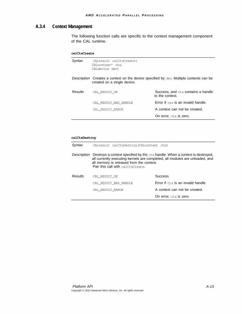
A M D A C C E L E R A T E D P A R A L L E L P R O C E S S I N G
Platform API A-13Copyright © 2010 Advanced Micro Devices, Inc. All rights reserved.
A.3.4 Context Management
The following function calls are specific to the context management component of the CAL runtime.
calCtxCreate
Syntax CALresult calCtxCreate(CALcontext* ctx, CALdevice dev)
Description Creates a context on the device specified by dev. Multiple contexts can be created on a single device.
Results CAL_RESULT_OK Success, and ctx contains a handle to the context.
CAL_RESULT_BAD_HANDLE Error if res is an invalid handle.
CAL_RESULT_ERROR A context can not be created.
On error, ctx is zero.
calCtxDestroy
Syntax CALresult calCtxDestroy(CALcontext ctx)
Description Destroys a context specified by the ctx handle. When a context is destroyed, all currently executing kernels are completed, all modules are unloaded, and all memory is released from the context.Pair this call with calCtxCreate.
Results CAL_RESULT_OK Success.
CAL_RESULT_BAD_HANDLE Error if ctx is an invalid handle
CAL_RESULT_ERROR A context can not be created.
On error, ctx is zero.
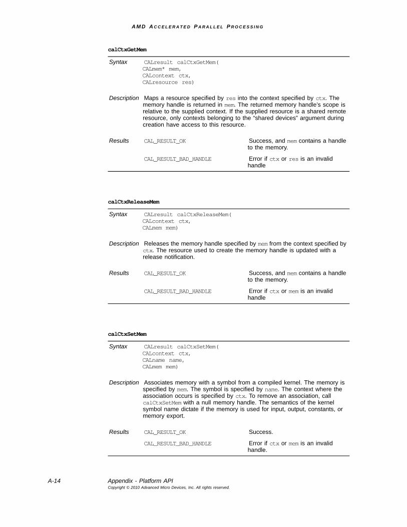
A M D A C C E L E R A T E D P A R A L L E L P R O C E S S I N G
A-14 Appendix - Platform APICopyright © 2010 Advanced Micro Devices, Inc. All rights reserved.
calCtxGetMem
Syntax CALresult calCtxGetMem(CALmem* mem, CALcontext ctx, CALresource res)
Description Maps a resource specified by res into the context specified by ctx. The memory handle is returned in mem. The returned memory handle’s scope is relative to the supplied context. If the supplied resource is a shared remote resource, only contexts belonging to the “shared devices” argument during creation have access to this resource.
Results CAL_RESULT_OK Success, and mem contains a handle to the memory.
CAL_RESULT_BAD_HANDLE Error if ctx or res is an invalid handle
calCtxReleaseMem
Syntax CALresult calCtxReleaseMem(CALcontext ctx, CALmem mem)
Description Releases the memory handle specified by mem from the context specified by ctx. The resource used to create the memory handle is updated with a release notification.
Results CAL_RESULT_OK Success, and mem contains a handle to the memory.
CAL_RESULT_BAD_HANDLE Error if ctx or mem is an invalid handle
calCtxSetMem
Syntax CALresult calCtxSetMem(CALcontext ctx, CALname name, CALmem mem)
Description Associates memory with a symbol from a compiled kernel. The memory is specified by mem. The symbol is specified by name. The context where the association occurs is specified by ctx. To remove an association, call calCtxSetMem with a null memory handle. The semantics of the kernel symbol name dictate if the memory is used for input, output, constants, or memory export.
Results CAL_RESULT_OK Success.
CAL_RESULT_BAD_HANDLE Error if ctx or mem is an invalid handle.
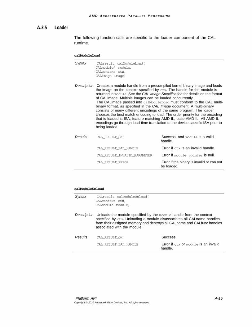
A M D A C C E L E R A T E D P A R A L L E L P R O C E S S I N G
Platform API A-15Copyright © 2010 Advanced Micro Devices, Inc. All rights reserved.
A.3.5 Loader
The following function calls are specific to the loader component of the CAL runtime.
calModuleLoad
Syntax CALresult calModuleLoad(CALmodule* module,CALcontext ctx,CALimage image)
Description Creates a module handle from a precompiled kernel binary image and loads the image on the context specified by ctx. The handle for the module is returned in module. See the CAL Image Specification for details on the format of CALimage. Multiple images can be loaded concurrently.The CALimage passed into calModuleLoad must conform to the CAL multi-binary format, as specified in the CAL Image document. A multi-binary consists of many different encodings of the same program. The loader chooses the best match encoding to load. The order priority for the encoding that is loaded is ISA, feature matching AMD IL, base AMD IL. All AMD IL encodings go through load-time translation to the device-specific ISA prior to being loaded.
Results CAL_RESULT_OK Success, and module is a valid handle.
CAL_RESULT_BAD_HANDLE Error if ctx is an invalid handle.
CAL_RESULT_INVALID_PARAMETER Error if module pointer is null.
CAL_RESULT_ERROR Error if the binary is invalid or can not be loaded.
calModuleUnload
Syntax CALresult calModuleUnload(CALcontext ctx, CALmodule module)
Description Unloads the module specified by the module handle from the context specified by ctx. Unloading a module disassociates all CALname handles from their assigned memory and destroys all CALname and CALfunc handles associated with the module.
Results CAL_RESULT_OK Success.
CAL_RESULT_BAD_HANDLE Error if ctx or module is an invalid handle.
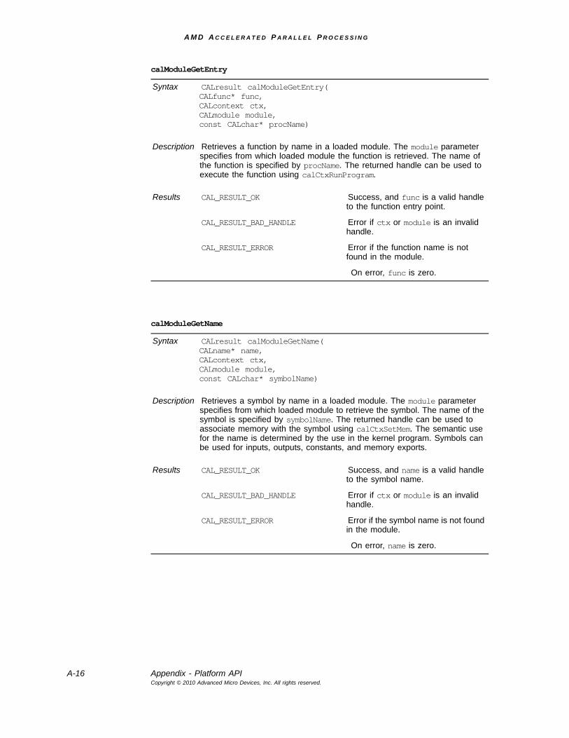
A M D A C C E L E R A T E D P A R A L L E L P R O C E S S I N G
A-16 Appendix - Platform APICopyright © 2010 Advanced Micro Devices, Inc. All rights reserved.
calModuleGetEntry
Syntax CALresult calModuleGetEntry(CALfunc* func,CALcontext ctx,CALmodule module,const CALchar* procName)
Description Retrieves a function by name in a loaded module. The module parameter specifies from which loaded module the function is retrieved. The name of the function is specified by procName. The returned handle can be used to execute the function using calCtxRunProgram.
Results CAL_RESULT_OK Success, and func is a valid handle to the function entry point.
CAL_RESULT_BAD_HANDLE Error if ctx or module is an invalid handle.
CAL_RESULT_ERROR Error if the function name is not found in the module.
On error, func is zero.
calModuleGetName
Syntax CALresult calModuleGetName(CALname* name,CALcontext ctx,CALmodule module,const CALchar* symbolName)
Description Retrieves a symbol by name in a loaded module. The module parameter specifies from which loaded module to retrieve the symbol. The name of the symbol is specified by symbolName. The returned handle can be used to associate memory with the symbol using calCtxSetMem. The semantic use for the name is determined by the use in the kernel program. Symbols can be used for inputs, outputs, constants, and memory exports.
Results CAL_RESULT_OK Success, and name is a valid handle to the symbol name.
CAL_RESULT_BAD_HANDLE Error if ctx or module is an invalid handle.
CAL_RESULT_ERROR Error if the symbol name is not found in the module.
On error, name is zero.
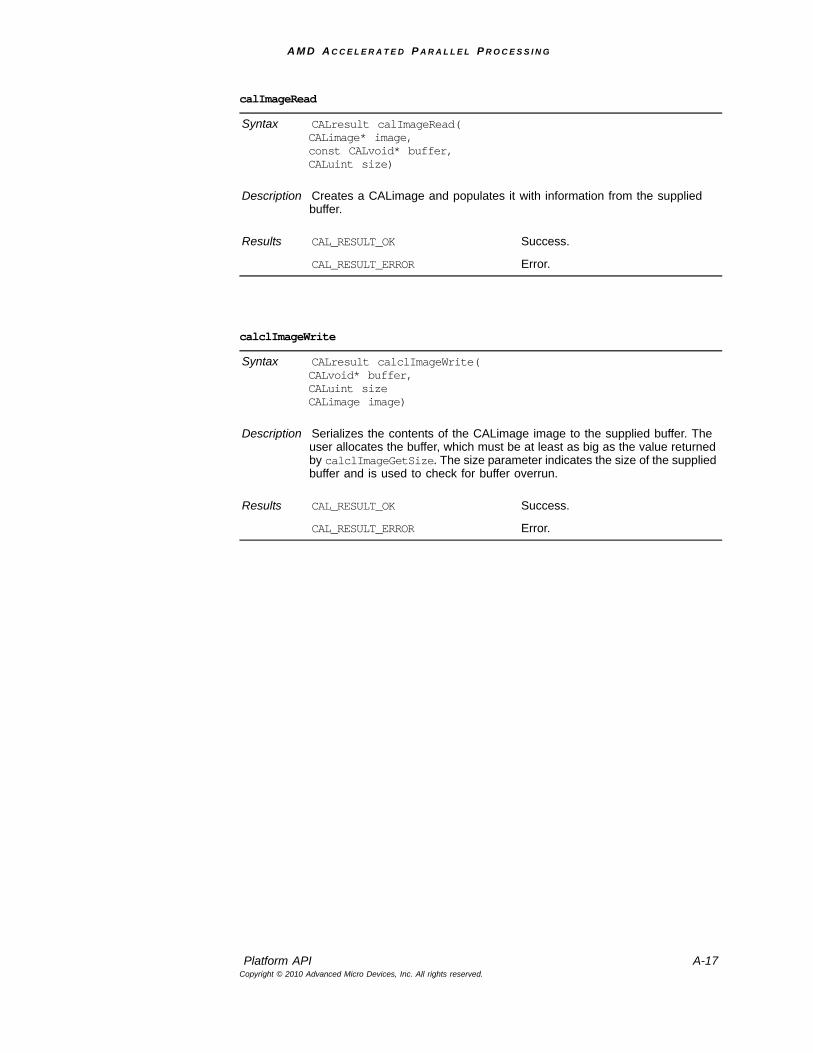
A M D A C C E L E R A T E D P A R A L L E L P R O C E S S I N G
Platform API A-17Copyright © 2010 Advanced Micro Devices, Inc. All rights reserved.
calImageRead
Syntax CALresult calImageRead(CALimage* image,const CALvoid* buffer,CALuint size)
Description Creates a CALimage and populates it with information from the supplied buffer.
Results CAL_RESULT_OK Success.
CAL_RESULT_ERROR Error.
calclImageWrite
Syntax CALresult calclImageWrite(CALvoid* buffer,CALuint sizeCALimage image)
Description Serializes the contents of the CALimage image to the supplied buffer. The user allocates the buffer, which must be at least as big as the value returned by calclImageGetSize. The size parameter indicates the size of the supplied buffer and is used to check for buffer overrun.
Results CAL_RESULT_OK Success.
CAL_RESULT_ERROR Error.
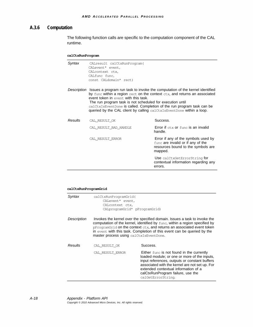
A M D A C C E L E R A T E D P A R A L L E L P R O C E S S I N G
A-18 Appendix - Platform APICopyright © 2010 Advanced Micro Devices, Inc. All rights reserved.
A.3.6 Computation
The following function calls are specific to the computation component of the CAL runtime.
calCtxRunProgram
Syntax CALresult calCtxRunProgram(CALevent* event, CALcontext ctx,CALfunc func,const CALdomain* rect)
Description Issues a program run task to invoke the computation of the kernel identified by func within a region rect on the context ctx, and returns an associated event token in event with this task.The run program task is not scheduled for execution until calCtxIsEventDone is called. Completion of the run program task can be queried by the CAL client by calling calCtxIsEventDone within a loop.
Results CAL_RESULT_OK Success.
CAL_RESULT_BAD_HANDLE Error if ctx or func is an invalid handle.
CAL_RESULT_ERROR Error if any of the symbols used by func are invalid or if any of the resources bound to the symbols are mapped.
Use calCtxGetErrorString for contextual information regarding any errors.
calCtxRunProgramGrid
Syntax calCtxRunProgramGrid(CALevent* event, CALcontext ctx, CALprogramGrid* pProgramGrid)
Description Invokes the kernel over the specified domain. Issues a task to invoke the computation of the kernel, identified by func, within a region specified by pProgramGrid on the context ctx, and returns an associated event token in event with this task. Completion of this event can be queried by the master process using calCtxIsEventDone.
Results CAL_RESULT_OK Success.
CAL_RESULT_ERROR Either func is not found in the currently loaded module; or one or more of the inputs, input references, outputs or constant buffers associated with the kernel are not set up. For extended contextual information of a calCtxRunProgram failure, use the calGetErrorString.
A M D A C C E L E R A T E D P A R A L L E L P R O C E S S I N G
Platform API A-19Copyright © 2010 Advanced Micro Devices, Inc. All rights reserved.
calCtxRunProgramGridArray
Syntax calCtxRunProgramGridArray(CALevent* event, CALcontext ctx, CALprogramGridArray* pGridArray)
Description Invokes the kernel array over the specified domain(s). Invokes the computation of the kernel arrays, identified by func, within a region specified by pGridArray on the context ctx and returns an associated event token in event with this task. Completion of this event can be queried by the master process using calCtxIsEventDone.
Results CAL_RESULT_OK Success.
CAL_RESULT_ERROR Either func is not found in the currently loaded module; or one or more of the inputs, input references, outputs or constant buffers associated with the kernel are not set up. For extended contextual information of a calCtxRunProgram failure, use the calGetErrorString.
calMemCopy
Syntax CALresult calMemCopy(CALevent* event,CALcontext ctx,CALmem srcMem,CALmem destMem,CALuint flags)
Description Issues a task to copy data from a source memory handle to a destination memory handle. An event is associated with this task and is returned in event, and completion of this event can be queried by the master process using calCtxIsEventDone. Data can be copied between memory handles from:• remote system memory to device local memory,• remote system memory to remote system memory,• device local memory to remote system memory,• device local memory to same device local memory,• device local memory to a different device local memory. The memory is copied by the context ctx. It can be placed in a separate queue or the primary calCtxRunProgram queue of context ctx.
Results CAL_RESULT_OK Success, and event contains the event identifier that a client can poll to query completeness.
CAL_RESULT_BAD_HANDLE Error if ctx, srcMem, or dstMem is an invalid handle.
CAL_RESULT_ERROR Error if the source and destination memory have different sizes or formats.
On error, event is zero.
A M D A C C E L E R A T E D P A R A L L E L P R O C E S S I N G
A-20 Appendix - Platform APICopyright © 2010 Advanced Micro Devices, Inc. All rights reserved.
A.3.7 Error Reporting
Error reporting is encoded in the return code of nearly every platform function call. The CAL API can provide contextual information about an error.
calCtxIsEventDone
Syntax CALresult calCtxIsEventDone(CALcontext ctx, CALevent event)
Description This function:Schedules an event specified by event for execution. Permits a CAL client to query if an event, specified by event, on the context, ctx, has completed.
Results CAL_RESULT_OK The Run Program or Mem Copy associated with the event identifier has completed.
CAL_RESULT_PENDING Returned for events that have not completed.
CAL_RESULT_BAD_HANDLE Error if ctx or event is an invalid handle.
calCtxFlush
Syntax CALresult calCtxFlush (CALcontext ctx)
Description Flushes all the queues on the supplied context ctx. Calling calCtxFlush causes all queued commands to be submitted to the device.
Results CAL_RESULT_OK Success.
CAL_RESULT_ERROR Error.
calGetErrorString
Syntax const CALchar* calGetErrorString(void);
Description Returns a contextual string regarding the nature of the an error returned by a CAL API call. The error string represents global state to the CAL runtime. The error state is updated on every call to the CAL API. The error string is returned by the function call and is null terminated.
A M D A C C E L E R A T E D P A R A L L E L P R O C E S S I N G
Extensions A-21Copyright © 2010 Advanced Micro Devices, Inc. All rights reserved.
A.4 ExtensionsThe CAL API supports extensions to the core. Extensions are optional, and a CAL client can query their support. The extension mechanism provides future functionality and improvement without changing the overall ABI of the CAL libraries. Likewise, not all extensions are available on all platforms.
A.4.1 Extension Functions
The following is a description of the extension functions.
calExtSupported
Syntax CALresult calExtSupported (CALextid extid)
Description Queries if an extension is supported by the implementation. The list of extensions is listed in Structures, on page A-31.
Results CAL_RESULT_OK Extension is supported.
CAL_RESULT_NOT_SUPPORTED Extension is not supported.
calExtGetVersion
Syntax CALresult calExtGetVersion(CALuint* major, CALuint* minor, CALextid extid)
Description Returns the version number of a supported extension. The format of the version number is in major.minor form. The list of extensions is listed in Section A.5.2, “Structures.”
Results CAL_RESULT_OK Success, and major and minor contain the returned values.
CAL_RESULT_NOT_SUPPORTED Extension is not supported.
A M D A C C E L E R A T E D P A R A L L E L P R O C E S S I N G
A-22 Appendix - ExtensionsCopyright © 2010 Advanced Micro Devices, Inc. All rights reserved.
A.4.2 Interoperability Extensions
A.4.2.1 Direct3D 9 API
The following function calls are part of the Direct3D 9 API extension.
calExtGetProc
Syntax CALresult calExtGetProc(CALextproc* proc,CALextid extid,const CALchar* procname)
Description Returns a pointer to the function for the specified extension. The extension to the query is specified by the extid parameter. The name of the function to get a pointer to is specified by procname. The list of extensions is listed in Structures, on page A-31. The list of functions is in Section A.5, “CAL API Types, Structures, and Enumerations,” page A-30.
Results CAL_RESULT_OK Success, and proc contains a pointer to the function.
CAL_RESULT_NOT_SUPPORTED Error if either the extid is not valid or the function name was not found.
On error, proc is null.
calD3D9Associate
Syntax CALresult calD3D9Associate(CALdevice dev, IDirect3DDevice9* d3dDevice)
Description Initializes the CAL to Direct3D 9 interoperability, associating the CALdevice dev with the IDirect3DDevice9 d3dDevice.This function must be called before any other Direct3D 9 interoperability calls are made.
Results CAL_RESULT_ERROR Interoperability not possible.
CAL_RESULT_OK Success.
A M D A C C E L E R A T E D P A R A L L E L P R O C E S S I N G
Extensions A-23Copyright © 2010 Advanced Micro Devices, Inc. All rights reserved.
A.4.2.2 Direct3D 10 API
The following function calls are part of the Direct3D 10 API extension.
calD3D9MapSurface
Syntax CALresult calD3D9MapSurface(CALresource* res, CALdevice dev, IDirect3DSurface9* surf, HANDLE shareHandle)
Description Maps the memory associated with IDirect3DSurface9 surf into the returned CALresource res. This function call can be used to map surfaces that are part of textures, render targets, or off-screen surfaces. The surface must have been created in the D3DPOOL_DEFAULT pool. Use only non-mipmapped textures with calD3D9MapSurface. The CAL resource format matches the D3DFORMAT.Once a resource has been created with calD3D9MapSurface, it can be used like any other CALresource. Before releasing the IDirect3DSurface9, the resource must be freed with calResFree.shareHandle must be the pSharedHandle value returned when the surface or texture was created.
Results CAL_RESULT_OK Success.
CAL_RESULT_ERROR Indicates that surf cannot be mapped on dev.
calD3D10Associate
Syntax CALresult calD3D10Associate(CALDevice dev, ID3D10Device* d3dDevice)
Description Initializes the CAL Direct3D 10 interoperability, associating the CALdevice dev with the ID3D10Device d3dDevice. This function must be called before any other Direct3D 10 interoperability calls are made.
Results CAL_RESULT_ERROR Interoperability not possible.
CAL_RESULT_OK Success.
A M D A C C E L E R A T E D P A R A L L E L P R O C E S S I N G
A-24 Appendix - ExtensionsCopyright © 2010 Advanced Micro Devices, Inc. All rights reserved.
A.4.3 Counters
The following are descriptions of the counter functions.
calD3D10MapResource
Syntax CALresult calD3D10MapResource(CALresource* res, CALdevice dev, ID3D10Resource* d3dres, HANDLE shareHandle)
Description Maps the memory associated with d3dres into a CALresource, returned in res. The resource must have been created with the D3D10_RESOURCE_MISC_SHARED flag.Once a resource has been created with calD3D10MapResource, it can be used like any other CALresource. Before releasing the ID3D10Resource, the resource must be freed with calResFree.shareHandle must be obtained by getting an IDXGI resource interface from the D3D resource. The sharehandle then can be retrieved with IDXGI::GetSharedHandle.
Results CAL_RESULT_OK Success.
CAL_RESULT_ERROR Indicates that surf cannot be mapped on dev.
calCtxCreateCounter
Syntax CALresult calCtxCreateCounter(CALcounter* counter,CALcontext ctx,CALcountertype type)
Description Create a counter object. The counter is created on the specified context ctx and is of type type. Supported counters are:
CAL_COUNTER_IDLE Percentage of time the stream processor is idle between Begin/End delimiters.
CAL_COUNTER_INPUT_CACHE_HIT_RATE
Percentage of input memory requests that hit the cache.
Counter activity is bracketed by a Begin/End pair. All activity to be considered must be between calCtxBeginCounter and calCtxEndCounter. Any number of calCtxRunProgram calls can exist between the Begin and End calls.
Results CAL_RESULT_OK Success, and a handle to the counter is returned in counter.
CAL_RESULT_BAD_HANDLE Error if ctx is an invalid handle.
A M D A C C E L E R A T E D P A R A L L E L P R O C E S S I N G
Extensions A-25Copyright © 2010 Advanced Micro Devices, Inc. All rights reserved.
calCtxDestroyCounter
Syntax CALresult calCtxDestroyCounter(CALcontext ctx, CALcounter counter)
Description Destroys a created counter object. The counter to destroy is specified by counter on the context specified by ctx. If a counter is destroyed between calCtxBeginCounter and calCtxEndCounter, CAL_RESULT_BUSY is returned.
Results CAL_RESULT_OK Success.
CAL_RESULT_BAD_HANDLE Error if called between Begin and End.
calCtxBeginCounter
Syntax CALresult calCtxBeginCounter(CALcontext ctx, CALcounter counter)
Description Initiates counting on the specified counter. Counters can be started only in a context. The counter is specified by counter. The context to start the counter on is specified by ctx.
Results CAL_RESULT_OK Success.
CAL_RESULT_BAD_HANDLE Error if either ctx or counter is an invalid handle.
CAL_RESULT_ALREADY Error if calCtxBeginCounter has been called on the same counter without ever calling calCtxEndCounter.
On error, the state is as if calCtxBeginCounter had not been called.
A M D A C C E L E R A T E D P A R A L L E L P R O C E S S I N G
A-26 Appendix - ExtensionsCopyright © 2010 Advanced Micro Devices, Inc. All rights reserved.
A.4.4 Sampler Parameter Extensions
These extensions let the applications change the sampler state for the inputs to the program, or read back the current sampler state for a given sampler name. They take in a CALname that represents the sampler to be updated, or for which parameters are read back. The extensions also take in pre-defined parameters that specify which sampler state to set or read back.
calCtxEndCounter
Syntax CALresult calCtxEndCounter(CALcontext ctx, CALcounter)
Description Ends counting on the specified counter. A counter can be ended only in the same context in which it was started. Counters can be ended once they are started by calCtxBeginCounter.
Results CAL_RESULT_OK Success.
CAL_RESULT_BAD_HANDLE Error if either ctx or counter is an invalid handle.
CAL_RESULT_ERROR Error if calCtxEndCounter is called without having called calCtxBeginCounter.
On error, the CAL API behaves as if calCtxEndCounter had not been called.
calCtxGetCounter
Syntax CALresult calCtxGetCounter(CALfloat* result,CALcontext ctx,CALcounter counter)
Description Retrieves the results of a counter. The value of the results is a floating point number between 0.0 and 1.0 whose meaning is shown in the description for calCtxCreateCounter, on page A-24. The results of a counter might not be available immediately. The counter results can be polled for availability, or the last calCtxRunProgram returned event can be polled for availability.
Results CAL_RESULT_OK Success, and result contains the result of the counter.
CAL_RESULT_BAD_HANDLE Error if either ctx or counter is an invalid handle.
CAL_RESULT_PENDING Counter results are not available.
On error, result is 0.0.
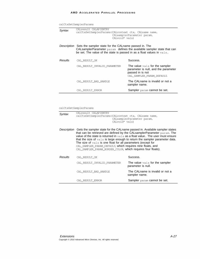
A M D A C C E L E R A T E D P A R A L L E L P R O C E S S I N G
Extensions A-27Copyright © 2010 Advanced Micro Devices, Inc. All rights reserved.
calCtxSetSamplerParams
Syntax CALresult CALAPIENTRYcalCtxSetSamplerParams(CALcontext ctx, CALname name, CALsamplerParameter param, CALvoid* vals)
Description Sets the sampler state for the CALname passed in. The CALsamplerParameter param defines the available sampler state that can be set. The value of the state is passed in as a float values in vals.
Results CAL_RESULT_OK Success.
CAL_RESULT_INVALID_PARAMETER The value vals for the sampler parameter is null, and the parameter passed in is not CAL_SAMPLER_PARAM_DEFAULT.
CAL_RESULT_BAD_HANDLE The CALname is invalid or not a sampler name.
CAL_RESULT_ERROR Sampler param cannot be set.
calCtxGetSamplerParams
Syntax CALresult CALAPIENTRYcalCtxGetSamplerParams(CALcontext ctx, CALname name, CALsamplerParameter param, CALvoid* vals)
Description Gets the sampler state for the CALname passed in. Available sampler states that can be retrieved are defined by the CALsamplerParameter param. The value of the state is returned in vals as a float value. The user must ensure that the size of vals is large enough to return the sampler parameter data. The size of vals is one float for all parameters (except for CAL_SAMPLER_PARAM_DEFAULT, which requires nine floats, and CAL_SAMPLER_PARAM_BORDER_COLOR, which requires four floats).
Results CAL_RESULT_OK Success.
CAL_RESULT_INVALID_PARAMETER The value vals for the sampler parameter is null.
CAL_RESULT_BAD_HANDLE The CALname is invalid or not a sampler name.
CAL_RESULT_ERROR Sampler param cannot be set.
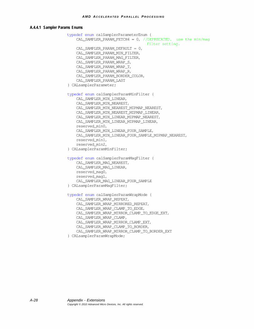
A M D A C C E L E R A T E D P A R A L L E L P R O C E S S I N G
A-28 Appendix - ExtensionsCopyright © 2010 Advanced Micro Devices, Inc. All rights reserved.
A.4.4.1 Sampler Params Enumstypedef enum calSamplerParameterEnum { CAL_SAMPLER_PARAM_FETCH4 = 0, //DEPRECATED. use the min/mag
filter setting. CAL_SAMPLER_PARAM_DEFAULT = 0, CAL_SAMPLER_PARAM_MIN_FILTER, CAL_SAMPLER_PARAM_MAG_FILTER, CAL_SAMPLER_PARAM_WRAP_S, CAL_SAMPLER_PARAM_WRAP_T, CAL_SAMPLER_PARAM_WRAP_R, CAL_SAMPLER_PARAM_BORDER_COLOR, CAL_SAMPLER_PARAM_LAST} CALsamplerParameter;
typedef enum calSamplerParamMinFilter { CAL_SAMPLER_MIN_LINEAR, CAL_SAMPLER_MIN_NEAREST, CAL_SAMPLER_MIN_NEAREST_MIPMAP_NEAREST, CAL_SAMPLER_MIN_NEAREST_MIPMAP_LINEAR, CAL_SAMPLER_MIN_LINEAR_MIPMAP_NEAREST, CAL_SAMPLER_MIN_LINEAR_MIPMAP_LINEAR, reserved_min0, CAL_SAMPLER_MIN_LINEAR_FOUR_SAMPLE, CAL_SAMPLER_MIN_LINEAR_FOUR_SAMPLE_MIPMAP_NEAREST, reserved_min1, reserved_min2, } CALsamplerParamMinFilter;
typedef enum calSamplerParamMagFilter { CAL_SAMPLER_MAG_NEAREST, CAL_SAMPLER_MAG_LINEAR, reserved_mag0, reserved_mag1, CAL_SAMPLER_MAG_LINEAR_FOUR_SAMPLE} CALsamplerParamMagFilter;
typedef enum calSamplerParamWrapMode { CAL_SAMPLER_WRAP_REPEAT, CAL_SAMPLER_WRAP_MIRRORED_REPEAT, CAL_SAMPLER_WRAP_CLAMP_TO_EDGE, CAL_SAMPLER_WRAP_MIRROR_CLAMP_TO_EDGE_EXT, CAL_SAMPLER_WRAP_CLAMP, CAL_SAMPLER_WRAP_MIRROR_CLAMP_EXT, CAL_SAMPLER_WRAP_CLAMP_TO_BORDER, CAL_SAMPLER_WRAP_MIRROR_CLAMP_TO_BORDER_EXT} CALsamplerParamWrapMode;
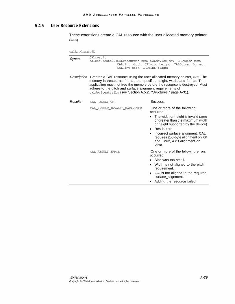
A M D A C C E L E R A T E D P A R A L L E L P R O C E S S I N G
Extensions A-29Copyright © 2010 Advanced Micro Devices, Inc. All rights reserved.
A.4.5 User Resource Extensions
These extensions create a CAL resource with the user allocated memory pointer (mem).
calResCreate2D
Syntax CALresult calResCreate2D(CALresource* res, CALdevice dev, CALvoid* mem,
CALuint width, CALuint height, CALformat format,CALuint size, CALuint flags)
Description Creates a CAL resource using the user allocated memory pointer, mem. The memory is treated as if it had the specified height, width, and format. The application must not free the memory before the resource is destroyed. Must adhere to the pitch and surface alignment requirements of caldeviceattribs (see Section A.5.2, “Structures,” page A-31).
Results CAL_RESULT_OK Success.
CAL_RESULT_INVALID_PARAMETER One or more of the following occurred:• The width or height is invalid (zero
or greater than the maximum width or height supported by the device).
• Res is zero.• Incorrect surface alignment. CAL
requires 256-byte alignment on XP and Linux, 4 kB alignment on Vista.
CAL_RESULT_ERROR One or more of the following errors occurred: • Size was too small.• Width is not aligned to the pitch
requirement.• mem is not aligned to the required
surface_alignment.• Adding the resource failed.
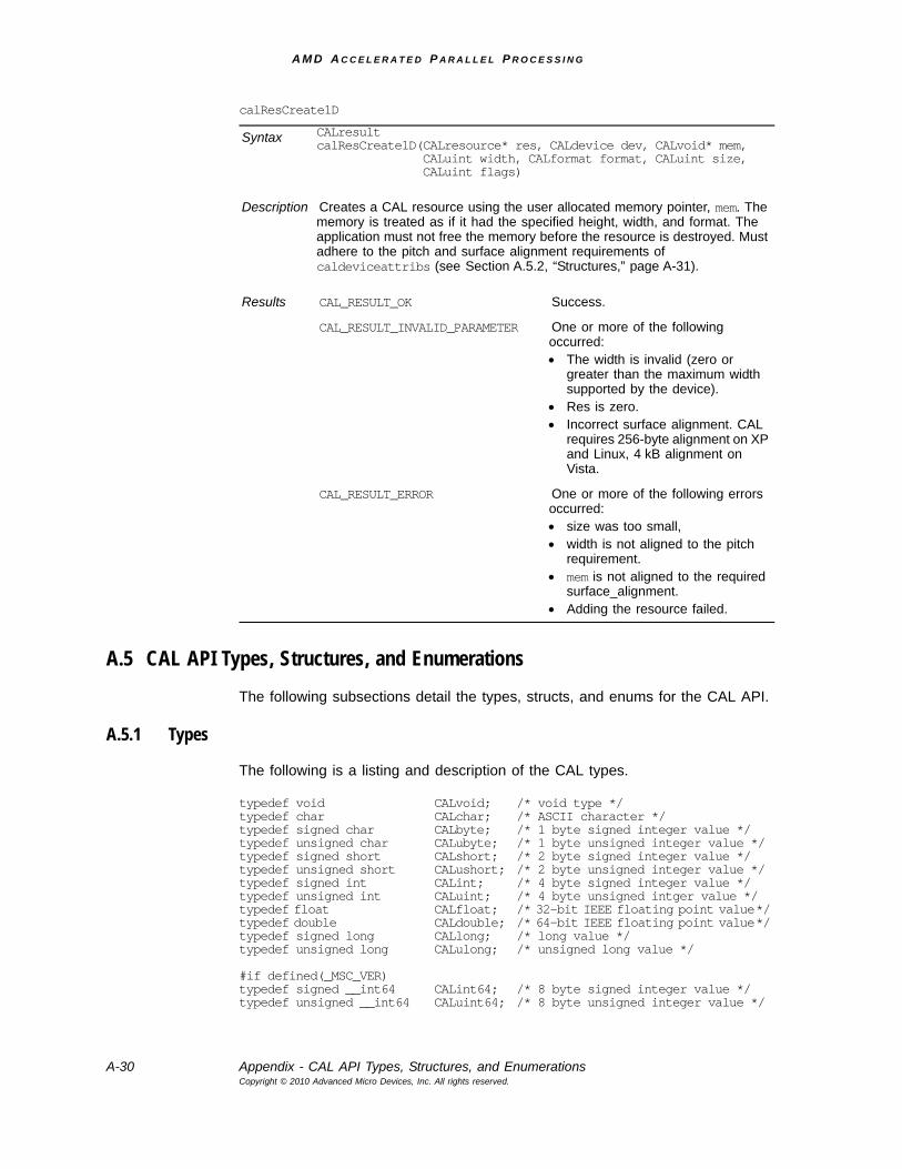
A M D A C C E L E R A T E D P A R A L L E L P R O C E S S I N G
A-30 Appendix - CAL API Types, Structures, and EnumerationsCopyright © 2010 Advanced Micro Devices, Inc. All rights reserved.
A.5 CAL API Types, Structures, and EnumerationsThe following subsections detail the types, structs, and enums for the CAL API.
A.5.1 Types
The following is a listing and description of the CAL types.
typedef void CALvoid; /* void type */typedef char CALchar; /* ASCII character */typedef signed char CALbyte; /* 1 byte signed integer value */typedef unsigned char CALubyte; /* 1 byte unsigned integer value */typedef signed short CALshort; /* 2 byte signed integer value */typedef unsigned short CALushort; /* 2 byte unsigned integer value */typedef signed int CALint; /* 4 byte signed integer value */typedef unsigned int CALuint; /* 4 byte unsigned intger value */typedef float CALfloat; /* 32-bit IEEE floating point value */typedef double CALdouble; /* 64-bit IEEE floating point value */typedef signed long CALlong; /* long value */typedef unsigned long CALulong; /* unsigned long value */
#if defined(_MSC_VER)typedef signed __int64 CALint64; /* 8 byte signed integer value */typedef unsigned __int64 CALuint64; /* 8 byte unsigned integer value */
calResCreate1D
Syntax CALresult calResCreate1D(CALresource* res, CALdevice dev, CALvoid* mem,
CALuint width, CALformat format, CALuint size,CALuint flags)
Description Creates a CAL resource using the user allocated memory pointer, mem. The memory is treated as if it had the specified height, width, and format. The application must not free the memory before the resource is destroyed. Must adhere to the pitch and surface alignment requirements of caldeviceattribs (see Section A.5.2, “Structures,” page A-31).
Results CAL_RESULT_OK Success.
CAL_RESULT_INVALID_PARAMETER One or more of the following occurred:• The width is invalid (zero or
greater than the maximum width supported by the device).
• Res is zero.• Incorrect surface alignment. CAL
requires 256-byte alignment on XP and Linux, 4 kB alignment on Vista.
CAL_RESULT_ERROR One or more of the following errors occurred: • size was too small,• width is not aligned to the pitch
requirement.• mem is not aligned to the required
surface_alignment.• Adding the resource failed.
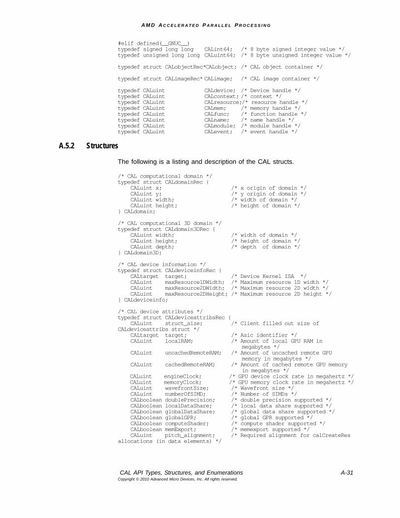
A M D A C C E L E R A T E D P A R A L L E L P R O C E S S I N G
CAL API Types, Structures, and Enumerations A-31Copyright © 2010 Advanced Micro Devices, Inc. All rights reserved.
#elif defined(__GNUC__)typedef signed long long CALint64; /* 8 byte signed integer value */typedef unsigned long long CALuint64; /* 8 byte unsigned integer value */
typedef struct CALobjectRec*CALobject; /* CAL object container */
typedef struct CALimageRec* CALimage; /* CAL image container */
typedef CALuint CALdevice; /* Device handle */typedef CALuint CALcontext; /* context */typedef CALuint CALresource;/* resource handle */typedef CALuint CALmem; /* memory handle */typedef CALuint CALfunc; /* function handle */typedef CALuint CALname; /* name handle */typedef CALuint CALmodule; /* module handle */typedef CALuint CALevent; /* event handle */
A.5.2 Structures
The following is a listing and description of the CAL structs.
/* CAL computational domain */typedef struct CALdomainRec { CALuint x; /* x origin of domain */ CALuint y; /* y origin of domain */ CALuint width; /* width of domain */ CALuint height; /* height of domain */} CALdomain;
/* CAL computational 3D domain */typedef struct CALdomain3DRec { CALuint width; /* width of domain */ CALuint height; /* height of domain */ CALuint depth; /* depth of domain */} CALdomain3D;
/* CAL device information */typedef struct CALdeviceinfoRec { CALtarget target; /* Device Kernel ISA */ CALuint maxResource1DWidth; /* Maximum resource 1D width */ CALuint maxResource2DWidth; /* Maximum resource 2D width */ CALuint maxResource2DHeight; /* Maximum resource 2D height */} CALdeviceinfo;
/* CAL device attributes */typedef struct CALdeviceattribsRec { CALuint struct_size; /* Client filled out size of CALdeviceattribs struct */ CALtarget target; /* Asic identifier */ CALuint localRAM; /* Amount of local GPU RAM in
megabytes */ CALuint uncachedRemoteRAM; /* Amount of uncached remote GPU
memory in megabytes */ CALuint cachedRemoteRAM; /* Amount of cached remote GPU memory
in megabytes */ CALuint engineClock; /* GPU device clock rate in megahertz */ CALuint memoryClock; /* GPU memory clock rate in megahertz */ CALuint wavefrontSize; /* Wavefront size */ CALuint numberOfSIMD; /* Number of SIMDs */ CALboolean doublePrecision; /* double precision supported */ CALboolean localDataShare; /* local data share supported */ CALboolean globalDataShare; /* global data share supported */ CALboolean globalGPR; /* global GPR supported */ CALboolean computeShader; /* compute shader supported */ CALboolean memExport; /* memexport supported */ CALuint pitch_alignment; /* Required alignment for calCreateRes allocations (in data elements) */
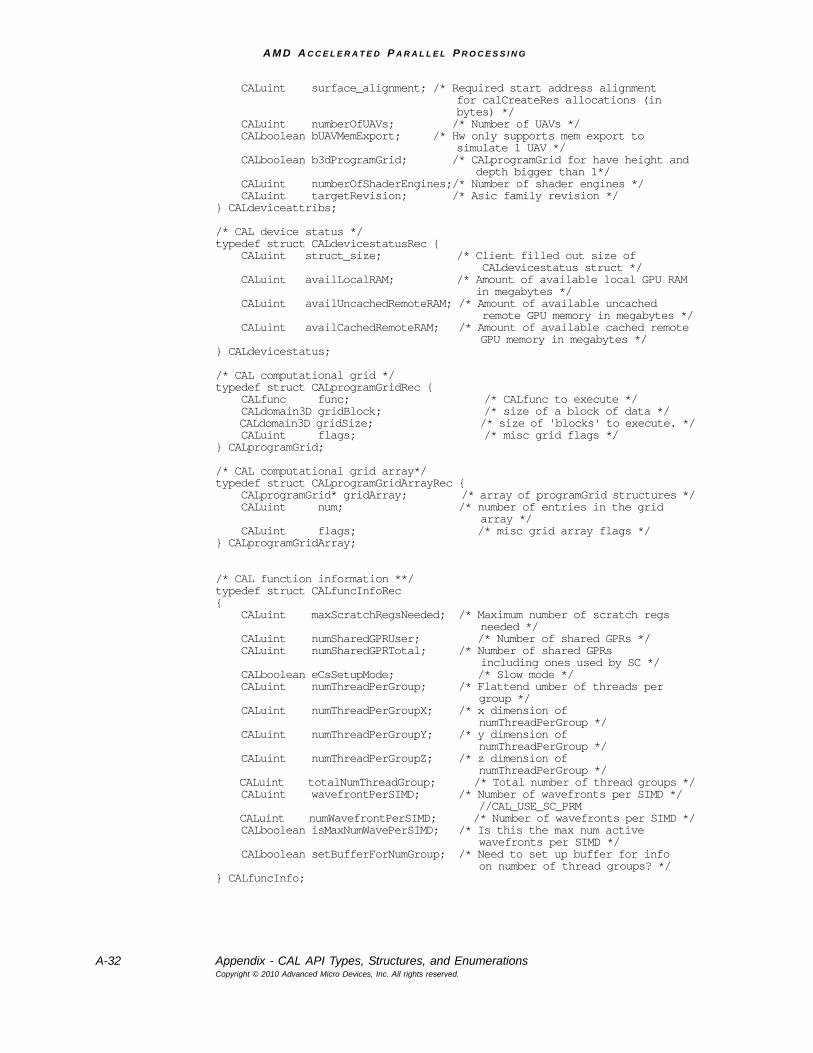
A M D A C C E L E R A T E D P A R A L L E L P R O C E S S I N G
A-32 Appendix - CAL API Types, Structures, and EnumerationsCopyright © 2010 Advanced Micro Devices, Inc. All rights reserved.
CALuint surface_alignment; /* Required start address alignmentfor calCreateRes allocations (inbytes) */
CALuint numberOfUAVs; /* Number of UAVs */ CALboolean bUAVMemExport; /* Hw only supports mem export to
simulate 1 UAV */ CALboolean b3dProgramGrid; /* CALprogramGrid for have height and
depth bigger than 1*/ CALuint numberOfShaderEngines;/* Number of shader engines */ CALuint targetRevision; /* Asic family revision */} CALdeviceattribs;
/* CAL device status */typedef struct CALdevicestatusRec { CALuint struct_size; /* Client filled out size of
CALdevicestatus struct */ CALuint availLocalRAM; /* Amount of available local GPU RAM
in megabytes */ CALuint availUncachedRemoteRAM; /* Amount of available uncached
remote GPU memory in megabytes */ CALuint availCachedRemoteRAM; /* Amount of available cached remote
GPU memory in megabytes */} CALdevicestatus;
/* CAL computational grid */typedef struct CALprogramGridRec { CALfunc func; /* CALfunc to execute */ CALdomain3D gridBlock; /* size of a block of data */ CALdomain3D gridSize; /* size of 'blocks' to execute. */ CALuint flags; /* misc grid flags */} CALprogramGrid;
/* CAL computational grid array*/typedef struct CALprogramGridArrayRec { CALprogramGrid* gridArray; /* array of programGrid structures */ CALuint num; /* number of entries in the grid
array */ CALuint flags; /* misc grid array flags */} CALprogramGridArray;
/* CAL function information **/typedef struct CALfuncInfoRec{ CALuint maxScratchRegsNeeded; /* Maximum number of scratch regs
needed */ CALuint numSharedGPRUser; /* Number of shared GPRs */ CALuint numSharedGPRTotal; /* Number of shared GPRs
including ones used by SC */ CALboolean eCsSetupMode; /* Slow mode */ CALuint numThreadPerGroup; /* Flattend umber of threads per
group */ CALuint numThreadPerGroupX; /* x dimension of
numThreadPerGroup */ CALuint numThreadPerGroupY; /* y dimension of
numThreadPerGroup */ CALuint numThreadPerGroupZ; /* z dimension of
numThreadPerGroup */ CALuint totalNumThreadGroup; /* Total number of thread groups */ CALuint wavefrontPerSIMD; /* Number of wavefronts per SIMD */
//CAL_USE_SC_PRM CALuint numWavefrontPerSIMD; /* Number of wavefronts per SIMD */ CALboolean isMaxNumWavePerSIMD; /* Is this the max num active
wavefronts per SIMD */ CALboolean setBufferForNumGroup; /* Need to set up buffer for info
on number of thread groups? */} CALfuncInfo;
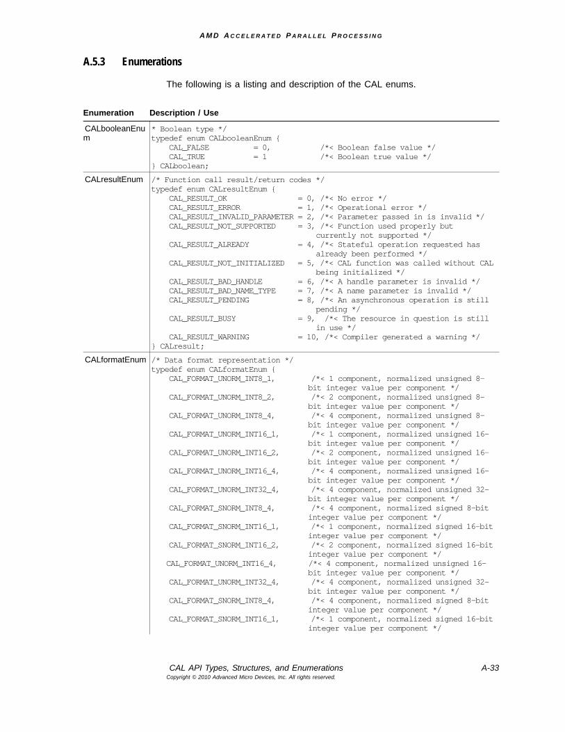
A M D A C C E L E R A T E D P A R A L L E L P R O C E S S I N G
CAL API Types, Structures, and Enumerations A-33Copyright © 2010 Advanced Micro Devices, Inc. All rights reserved.
A.5.3 Enumerations
The following is a listing and description of the CAL enums.
Enumeration Description / Use
CALbooleanEnum
* Boolean type */typedef enum CALbooleanEnum { CAL_FALSE = 0, /*< Boolean false value */ CAL_TRUE = 1 /*< Boolean true value */} CALboolean;
CALresultEnum /* Function call result/return codes */typedef enum CALresultEnum { CAL_RESULT_OK = 0, /*< No error */ CAL_RESULT_ERROR = 1, /*< Operational error */ CAL_RESULT_INVALID_PARAMETER = 2, /*< Parameter passed in is invalid */ CAL_RESULT_NOT_SUPPORTED = 3, /*< Function used properly but
currently not supported */ CAL_RESULT_ALREADY = 4, /*< Stateful operation requested has
already been performed */ CAL_RESULT_NOT_INITIALIZED = 5, /*< CAL function was called without CAL
being initialized */ CAL_RESULT_BAD_HANDLE = 6, /*< A handle parameter is invalid */ CAL_RESULT_BAD_NAME_TYPE = 7, /*< A name parameter is invalid */ CAL_RESULT_PENDING = 8, /*< An asynchronous operation is still
pending */ CAL_RESULT_BUSY = 9, /*< The resource in question is still
in use */ CAL_RESULT_WARNING = 10, /*< Compiler generated a warning */} CALresult;
CALformatEnum /* Data format representation */typedef enum CALformatEnum { CAL_FORMAT_UNORM_INT8_1, /*< 1 component, normalized unsigned 8-
bit integer value per component */ CAL_FORMAT_UNORM_INT8_2, /*< 2 component, normalized unsigned 8-
bit integer value per component */ CAL_FORMAT_UNORM_INT8_4, /*< 4 component, normalized unsigned 8-
bit integer value per component */ CAL_FORMAT_UNORM_INT16_1, /*< 1 component, normalized unsigned 16-
bit integer value per component */ CAL_FORMAT_UNORM_INT16_2, /*< 2 component, normalized unsigned 16-
bit integer value per component */ CAL_FORMAT_UNORM_INT16_4, /*< 4 component, normalized unsigned 16-
bit integer value per component */ CAL_FORMAT_UNORM_INT32_4, /*< 4 component, normalized unsigned 32-
bit integer value per component */ CAL_FORMAT_SNORM_INT8_4, /*< 4 component, normalized signed 8-bit
integer value per component */ CAL_FORMAT_SNORM_INT16_1, /*< 1 component, normalized signed 16-bit
integer value per component */ CAL_FORMAT_SNORM_INT16_2, /*< 2 component, normalized signed 16-bit
integer value per component */CAL_FORMAT_UNORM_INT16_4, /*< 4 component, normalized unsigned 16-
bit integer value per component */ CAL_FORMAT_UNORM_INT32_4, /*< 4 component, normalized unsigned 32-
bit integer value per component */ CAL_FORMAT_SNORM_INT8_4, /*< 4 component, normalized signed 8-bit
integer value per component */ CAL_FORMAT_SNORM_INT16_1, /*< 1 component, normalized signed 16-bit
integer value per component */
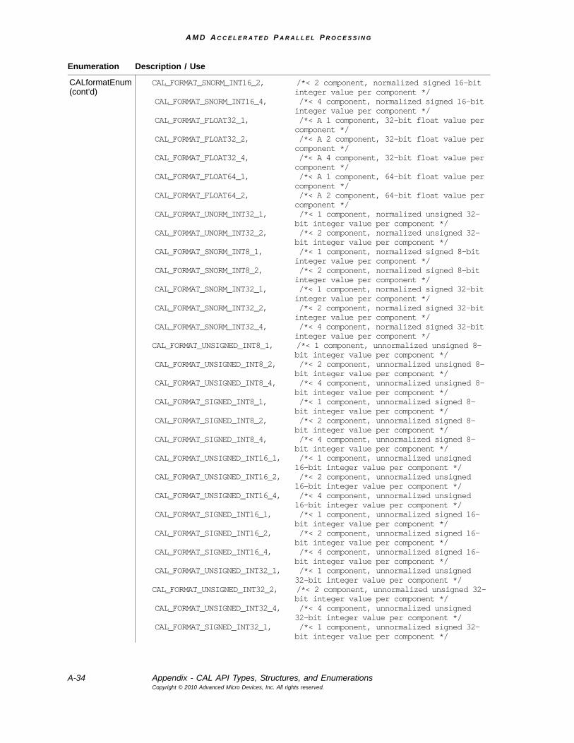
A M D A C C E L E R A T E D P A R A L L E L P R O C E S S I N G
A-34 Appendix - CAL API Types, Structures, and EnumerationsCopyright © 2010 Advanced Micro Devices, Inc. All rights reserved.
CALformatEnum(cont’d)
CAL_FORMAT_SNORM_INT16_2, /*< 2 component, normalized signed 16-bit integer value per component */
CAL_FORMAT_SNORM_INT16_4, /*< 4 component, normalized signed 16-bit integer value per component */
CAL_FORMAT_FLOAT32_1, /*< A 1 component, 32-bit float value per component */
CAL_FORMAT_FLOAT32_2, /*< A 2 component, 32-bit float value per component */
CAL_FORMAT_FLOAT32_4, /*< A 4 component, 32-bit float value per component */
CAL_FORMAT_FLOAT64_1, /*< A 1 component, 64-bit float value per component */
CAL_FORMAT_FLOAT64_2, /*< A 2 component, 64-bit float value per component */
CAL_FORMAT_UNORM_INT32_1, /*< 1 component, normalized unsigned 32-bit integer value per component */
CAL_FORMAT_UNORM_INT32_2, /*< 2 component, normalized unsigned 32-bit integer value per component */
CAL_FORMAT_SNORM_INT8_1, /*< 1 component, normalized signed 8-bit integer value per component */
CAL_FORMAT_SNORM_INT8_2, /*< 2 component, normalized signed 8-bit integer value per component */
CAL_FORMAT_SNORM_INT32_1, /*< 1 component, normalized signed 32-bit integer value per component */
CAL_FORMAT_SNORM_INT32_2, /*< 2 component, normalized signed 32-bit integer value per component */
CAL_FORMAT_SNORM_INT32_4, /*< 4 component, normalized signed 32-bit integer value per component */
CAL_FORMAT_UNSIGNED_INT8_1, /*< 1 component, unnormalized unsigned 8-bit integer value per component */
CAL_FORMAT_UNSIGNED_INT8_2, /*< 2 component, unnormalized unsigned 8-bit integer value per component */
CAL_FORMAT_UNSIGNED_INT8_4, /*< 4 component, unnormalized unsigned 8-bit integer value per component */
CAL_FORMAT_SIGNED_INT8_1, /*< 1 component, unnormalized signed 8-bit integer value per component */
CAL_FORMAT_SIGNED_INT8_2, /*< 2 component, unnormalized signed 8-bit integer value per component */
CAL_FORMAT_SIGNED_INT8_4, /*< 4 component, unnormalized signed 8-bit integer value per component */
CAL_FORMAT_UNSIGNED_INT16_1, /*< 1 component, unnormalized unsigned 16-bit integer value per component */
CAL_FORMAT_UNSIGNED_INT16_2, /*< 2 component, unnormalized unsigned 16-bit integer value per component */
CAL_FORMAT_UNSIGNED_INT16_4, /*< 4 component, unnormalized unsigned 16-bit integer value per component */
CAL_FORMAT_SIGNED_INT16_1, /*< 1 component, unnormalized signed 16-bit integer value per component */
CAL_FORMAT_SIGNED_INT16_2, /*< 2 component, unnormalized signed 16-bit integer value per component */
CAL_FORMAT_SIGNED_INT16_4, /*< 4 component, unnormalized signed 16-bit integer value per component */
CAL_FORMAT_UNSIGNED_INT32_1, /*< 1 component, unnormalized unsigned 32-bit integer value per component */
CAL_FORMAT_UNSIGNED_INT32_2, /*< 2 component, unnormalized unsigned 32-bit integer value per component */
CAL_FORMAT_UNSIGNED_INT32_4, /*< 4 component, unnormalized unsigned 32-bit integer value per component */
CAL_FORMAT_SIGNED_INT32_1, /*< 1 component, unnormalized signed 32-bit integer value per component */
Enumeration Description / Use
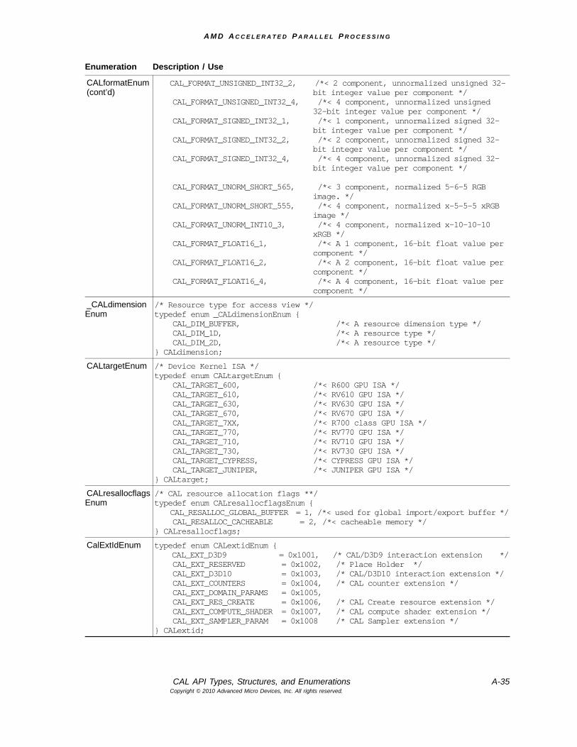
A M D A C C E L E R A T E D P A R A L L E L P R O C E S S I N G
CAL API Types, Structures, and Enumerations A-35Copyright © 2010 Advanced Micro Devices, Inc. All rights reserved.
CALformatEnum(cont’d)
CAL_FORMAT_UNSIGNED_INT32_2, /*< 2 component, unnormalized unsigned 32-bit integer value per component */
CAL_FORMAT_UNSIGNED_INT32_4, /*< 4 component, unnormalized unsigned 32-bit integer value per component */
CAL_FORMAT_SIGNED_INT32_1, /*< 1 component, unnormalized signed 32-bit integer value per component */
CAL_FORMAT_SIGNED_INT32_2, /*< 2 component, unnormalized signed 32-bit integer value per component */
CAL_FORMAT_SIGNED_INT32_4, /*< 4 component, unnormalized signed 32-bit integer value per component */
CAL_FORMAT_UNORM_SHORT_565, /*< 3 component, normalized 5-6-5 RGB image. */
CAL_FORMAT_UNORM_SHORT_555, /*< 4 component, normalized x-5-5-5 xRGB image */
CAL_FORMAT_UNORM_INT10_3, /*< 4 component, normalized x-10-10-10 xRGB */
CAL_FORMAT_FLOAT16_1, /*< A 1 component, 16-bit float value per component */
CAL_FORMAT_FLOAT16_2, /*< A 2 component, 16-bit float value per component */
CAL_FORMAT_FLOAT16_4, /*< A 4 component, 16-bit float value per component */
_CALdimensionEnum
/* Resource type for access view */typedef enum _CALdimensionEnum { CAL_DIM_BUFFER, /*< A resource dimension type */ CAL_DIM_1D, /*< A resource type */ CAL_DIM_2D, /*< A resource type */} CALdimension;
CALtargetEnum /* Device Kernel ISA */typedef enum CALtargetEnum { CAL_TARGET_600, /*< R600 GPU ISA */ CAL_TARGET_610, /*< RV610 GPU ISA */ CAL_TARGET_630, /*< RV630 GPU ISA */ CAL_TARGET_670, /*< RV670 GPU ISA */ CAL_TARGET_7XX, /*< R700 class GPU ISA */ CAL_TARGET_770, /*< RV770 GPU ISA */ CAL_TARGET_710, /*< RV710 GPU ISA */ CAL_TARGET_730, /*< RV730 GPU ISA */ CAL_TARGET_CYPRESS, /*< CYPRESS GPU ISA */ CAL_TARGET_JUNIPER, /*< JUNIPER GPU ISA */} CALtarget;
CALresallocflagsEnum
/* CAL resource allocation flags **/typedef enum CALresallocflagsEnum { CAL_RESALLOC_GLOBAL_BUFFER = 1, /*< used for global import/export buffer */ CAL_RESALLOC_CACHEABLE = 2, /*< cacheable memory */} CALresallocflags;
CalExtIdEnum typedef enum CALextidEnum { CAL_EXT_D3D9 = 0x1001, /* CAL/D3D9 interaction extension */ CAL_EXT_RESERVED = 0x1002, /* Place Holder */ CAL_EXT_D3D10 = 0x1003, /* CAL/D3D10 interaction extension */ CAL_EXT_COUNTERS = 0x1004, /* CAL counter extension */ CAL_EXT_DOMAIN_PARAMS = 0x1005, CAL_EXT_RES_CREATE = 0x1006, /* CAL Create resource extension */ CAL_EXT_COMPUTE_SHADER = 0x1007, /* CAL compute shader extension */ CAL_EXT_SAMPLER_PARAM = 0x1008 /* CAL Sampler extension */} CALextid;
Enumeration Description / Use
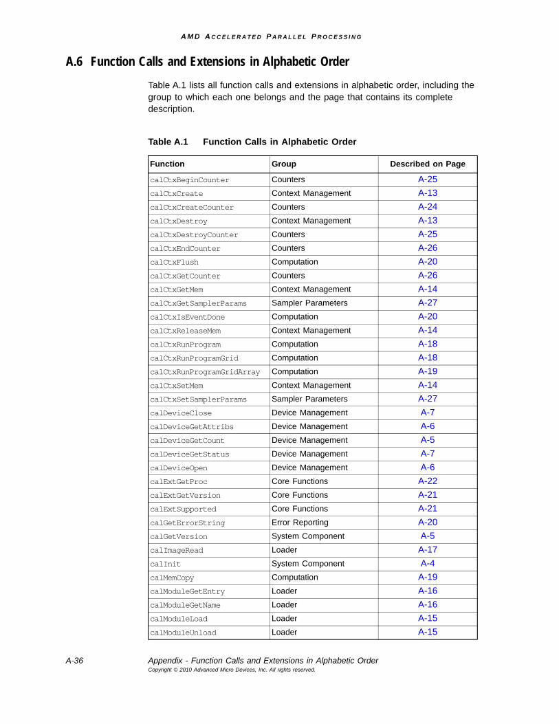
A M D A C C E L E R A T E D P A R A L L E L P R O C E S S I N G
A-36 Appendix - Function Calls and Extensions in Alphabetic OrderCopyright © 2010 Advanced Micro Devices, Inc. All rights reserved.
A.6 Function Calls and Extensions in Alphabetic OrderTable A.1 lists all function calls and extensions in alphabetic order, including the group to which each one belongs and the page that contains its complete description.
Table A.1 Function Calls in Alphabetic Order
Function Group Described on Page
calCtxBeginCounter Counters A-25calCtxCreate Context Management A-13calCtxCreateCounter Counters A-24calCtxDestroy Context Management A-13calCtxDestroyCounter Counters A-25calCtxEndCounter Counters A-26calCtxFlush Computation A-20calCtxGetCounter Counters A-26calCtxGetMem Context Management A-14calCtxGetSamplerParams Sampler Parameters A-27calCtxIsEventDone Computation A-20calCtxReleaseMem Context Management A-14calCtxRunProgram Computation A-18calCtxRunProgramGrid Computation A-18calCtxRunProgramGridArray Computation A-19calCtxSetMem Context Management A-14calCtxSetSamplerParams Sampler Parameters A-27calDeviceClose Device Management A-7calDeviceGetAttribs Device Management A-6calDeviceGetCount Device Management A-5calDeviceGetStatus Device Management A-7calDeviceOpen Device Management A-6calExtGetProc Core Functions A-22calExtGetVersion Core Functions A-21calExtSupported Core Functions A-21calGetErrorString Error Reporting A-20calGetVersion System Component A-5calImageRead Loader A-17calInit System Component A-4calMemCopy Computation A-19calModuleGetEntry Loader A-16calModuleGetName Loader A-16calModuleLoad Loader A-15calModuleUnload Loader A-15
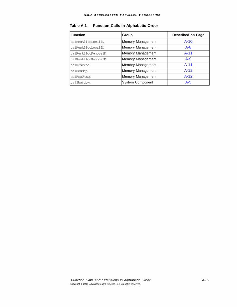
A M D A C C E L E R A T E D P A R A L L E L P R O C E S S I N G
Function Calls and Extensions in Alphabetic Order A-37Copyright © 2010 Advanced Micro Devices, Inc. All rights reserved.
calResAllocLocal1D Memory Management A-10calResAllocLocal2D Memory Management A-8calResAllocRemote1D Memory Management A-11calResAllocRemote2D Memory Management A-9calResFree Memory Management A-11calResMap Memory Management A-12calResUnmap Memory Management A-12calShutdown System Component A-5
Table A.1 Function Calls in Alphabetic Order
Function Group Described on Page

A M D A C C E L E R A T E D P A R A L L E L P R O C E S S I N G
A-38 Appendix - Function Calls and Extensions in Alphabetic OrderCopyright © 2010 Advanced Micro Devices, Inc. All rights reserved.
A M D A C C E L E R A T E D P A R A L L E L P R O C E S S I N G
AMD Compute Abstraction Layer (CAL) Programming Guide B-1Copyright © 2010 Advanced Micro Devices, Inc. All rights reserved.
Appendix B CAL Binary Format Specification
The AMD Compute Abstraction Layer (CAL) provides a forward-compatible interface to the high-performance, floating-point, parallel processor arrays found in AMD GPUs and in CPUs.
The computational model is processor-independent and lets the user easily switch from directing a computation from stream processor to CPU or vice versa. The API permits a dynamic load balancer to be written on top of CAL. CAL is a light-weight implementation that facilitates a compute platform such as OpenCL to be developed on top of it.
CAL is supported on the R6xx and newer generation of stream processors, as well as all CPU processors. CAL is available on both 32-bit and 64-bit versions of XP, Vista, and Linux. The CAL platform interface provides a binary interface to loading program modules. This documentation describes the format of the binary interface.
B.1 The CALimage Binary Interface The CAL platform interface provides a binary interface to loading program modules. This documentation describes the format of the binary interface. The CALimage executable file format must be in the Executable and Linking Format (ELF). ELF is specified as a component of the Tool Interface Standard (TIS), and its documentation is publicly available. This document assumes familiarity with ELF and details only the portions of the ELF file that are specific to loading programs.
The CALimage format is capable of containing multiple encodings of the same program. The encodings are any variation of intermediate formats, as well as hardware specific instruction sets. The intermediate format and hardware instruction set descriptions are described in separate documents, only the packaging of code streams is described here.
B.2 CALimage Format The CALimage format conforms to the Executable and Linking Format (ELF). The base structures and data types are defined by the ELF standard and are used in full in the CALimage specification.
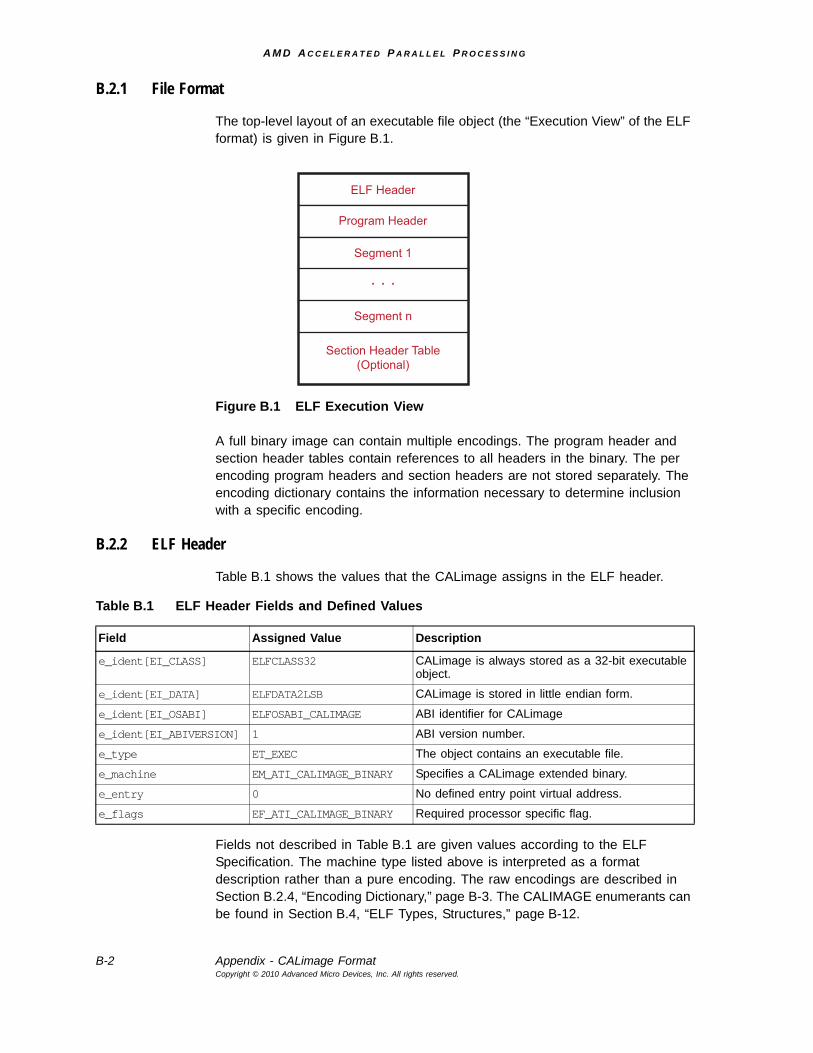
A M D A C C E L E R A T E D P A R A L L E L P R O C E S S I N G
B-2 Appendix - CALimage FormatCopyright © 2010 Advanced Micro Devices, Inc. All rights reserved.
B.2.1 File Format
The top-level layout of an executable file object (the “Execution View” of the ELF format) is given in Figure B.1.
Figure B.1 ELF Execution View
A full binary image can contain multiple encodings. The program header and section header tables contain references to all headers in the binary. The per encoding program headers and section headers are not stored separately. The encoding dictionary contains the information necessary to determine inclusion with a specific encoding.
B.2.2 ELF Header
Table B.1 shows the values that the CALimage assigns in the ELF header.
Fields not described in Table B.1 are given values according to the ELF Specification. The machine type listed above is interpreted as a format description rather than a pure encoding. The raw encodings are described in Section B.2.4, “Encoding Dictionary,” page B-3. The CALIMAGE enumerants can be found in Section B.4, “ELF Types, Structures,” page B-12.
ELF Header
Section Header Table(Optional)
Segment n
. . .
Segment 1
Program Header
Table B.1 ELF Header Fields and Defined Values
Field Assigned Value Description
e_ident[EI_CLASS] ELFCLASS32 CALimage is always stored as a 32-bit executable object.
e_ident[EI_DATA] ELFDATA2LSB CALimage is stored in little endian form.
e_ident[EI_OSABI] ELFOSABI_CALIMAGE ABI identifier for CALimage
e_ident[EI_ABIVERSION] 1 ABI version number.
e_type ET_EXEC The object contains an executable file.
e_machine EM_ATI_CALIMAGE_BINARY Specifies a CALimage extended binary.
e_entry 0 No defined entry point virtual address.
e_flags EF_ATI_CALIMAGE_BINARY Required processor specific flag.
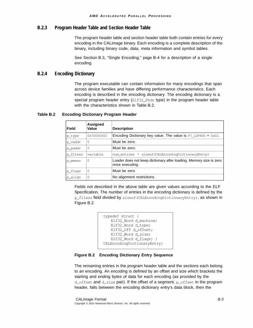
A M D A C C E L E R A T E D P A R A L L E L P R O C E S S I N G
CALimage Format B-3Copyright © 2010 Advanced Micro Devices, Inc. All rights reserved.
B.2.3 Program Header Table and Section Header Table
The program header table and section header table both contain entries for every encoding in the CALimage binary. Each encoding is a complete description of the binary, including binary code, data, meta information and symbol tables.
See Section B.3, “Single Encoding,” page B-4 for a description of a single encoding.
B.2.4 Encoding Dictionary
The program executable can contain information for many encodings that span across device families and have differing performance characteristics. Each encoding is described in the encoding dictionary. The encoding dictionary is a special program header entry (Elf32_Phdr type) in the program header table with the characteristics shown in Table B.2.
Fields not described in the above table are given values according to the ELF Specification. The number of entries in the encoding dictionary is defined by the p_filesz field divided by sizeof(CALEncodingDictionaryEntry), as shown in Figure B.2.
.
Figure B.2 Encoding Dictionary Entry Sequence
The remaining entries in the program header table and the sections each belong to an encoding. An encoding is defined by an offset and size which brackets the starting and ending bytes of data for each encoding (as provided by the d_offset and d_size pair). If the offset of a segment, p_offset in the program header, falls between the encoding dictionary entry’s data block, then the
Table B.2 Encoding Dictionary Program Header
Field Assigned Value Description
p_type 0x70000002 Encoding Dictionary key value. The value is PT_LOPROC + 0x02.
p_vaddr 0 Must be zero.
p_paddr 0 Must be zero.
p_filesz variable num_entries * sizeof(CALEncodingDictionaryEntry)
p_memsz 0 Loader does not keep dictionary after loading. Memory size is zero once executing.
p_flags 0 Must be zero.
p_align 0 No alignment restrictions.
typedef struct {Elf32_Word d_machine;Elf32_Word d_type;Elf32_Off d_offset;Elf32_Word d_size;Elf32_Word d_flags; }
CALEncodingDictionaryEntry;
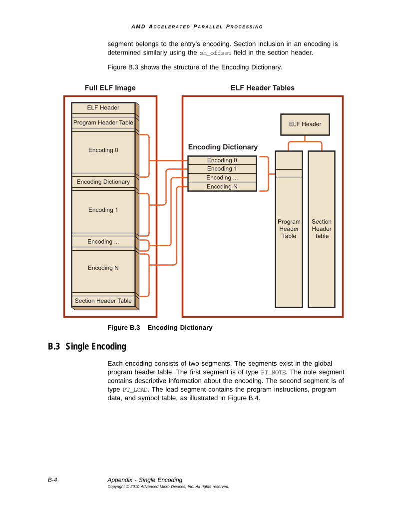
A M D A C C E L E R A T E D P A R A L L E L P R O C E S S I N G
B-4 Appendix - Single EncodingCopyright © 2010 Advanced Micro Devices, Inc. All rights reserved.
segment belongs to the entry’s encoding. Section inclusion in an encoding is determined similarly using the sh_offset field in the section header.
Figure B.3 shows the structure of the Encoding Dictionary.
Figure B.3 Encoding Dictionary
B.3 Single Encoding Each encoding consists of two segments. The segments exist in the global program header table. The first segment is of type PT_NOTE. The note segment contains descriptive information about the encoding. The second segment is of type PT_LOAD. The load segment contains the program instructions, program data, and symbol table, as illustrated in Figure B.4.
ELF Header
Program Header Table
Encoding 0
Encoding Dictionary
Encoding 1
Encoding ...
Encoding N
Section Header Table
ELF Header
ProgramHeaderTable
SectionHeaderTable
Full ELF Image ELF Header Tables
Encoding Dictionary
Encoding 0Encoding 1Encoding ...Encoding N
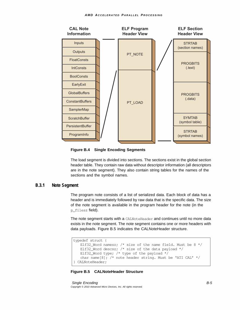
A M D A C C E L E R A T E D P A R A L L E L P R O C E S S I N G
Single Encoding B-5Copyright © 2010 Advanced Micro Devices, Inc. All rights reserved.
Figure B.4 Single Encoding Segments
The load segment is divided into sections. The sections exist in the global section header table. They contain raw data without descriptor information (all descriptors are in the note segment). They also contain string tables for the names of the sections and the symbol names.
B.3.1 Note Segment
The program note consists of a list of serialized data. Each block of data has a header and is immediately followed by raw data that is the specific data. The size of the note segment is available in the program header for the note (in the p_filesz field).
The note segment starts with a CALNoteHeader and continues until no more data exists in the note segment. The note segment contains one or more headers with data payloads. Figure B.5 indicates the CALNoteHeader structure.
Figure B.5 CALNoteHeader Structure
ELF ProgramHeader View
PT_NOTE
PT_LOAD
ELF SectionHeader View
STRTAB(section names)
PROGBITS(.text)
PROGBITS(.data)
SYMTAB(symbol table)
STRTAB(symbol names)
CAL NoteInformation
Inputs
Outputs
FloatConsts
IntConsts
BoolConsts
EarlyExit
GlobalBuffers
ConstantBuffers
SamplerMap
ScratchBuffer
PersistentBuffer
ProgramInfo
typedef struct { Elf32_Word namesz; /* size of the name field. Must be 8 */ Elf32_Word descsz; /* size of the data payload */ Elf32_Word type; /* type of the payload */ char name[8]; /* note header string. Must be “ATI CAL” */
} CALNoteHeader;
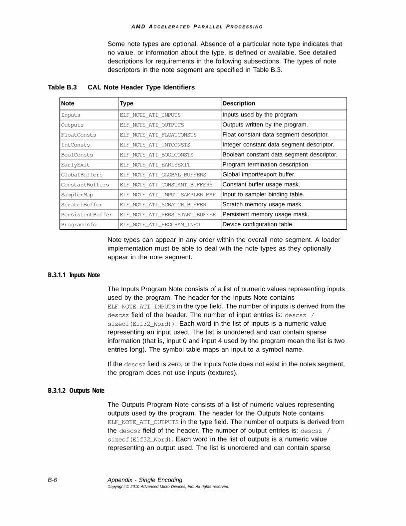
A M D A C C E L E R A T E D P A R A L L E L P R O C E S S I N G
B-6 Appendix - Single EncodingCopyright © 2010 Advanced Micro Devices, Inc. All rights reserved.
Some note types are optional. Absence of a particular note type indicates that no value, or information about the type, is defined or available. See detailed descriptions for requirements in the following subsections. The types of note descriptors in the note segment are specified in Table B.3.
Note types can appear in any order within the overall note segment. A loader implementation must be able to deal with the note types as they optionally appear in the note segment.
B.3.1.1 Inputs Note
The Inputs Program Note consists of a list of numeric values representing inputs used by the program. The header for the Inputs Note contains ELF_NOTE_ATI_INPUTS in the type field. The number of inputs is derived from the descsz field of the header. The number of input entries is: descsz / sizeof(Elf32_Word)). Each word in the list of inputs is a numeric value representing an input used. The list is unordered and can contain sparse information (that is, input 0 and input 4 used by the program mean the list is two entries long). The symbol table maps an input to a symbol name.
If the descsz field is zero, or the Inputs Note does not exist in the notes segment, the program does not use inputs (textures).
B.3.1.2 Outputs Note
The Outputs Program Note consists of a list of numeric values representing outputs used by the program. The header for the Outputs Note contains ELF_NOTE_ATI_OUTPUTS in the type field. The number of outputs is derived from the descsz field of the header. The number of output entries is: descsz / sizeof(Elf32_Word). Each word in the list of outputs is a numeric value representing an output used. The list is unordered and can contain sparse
Table B.3 CAL Note Header Type Identifiers
Note Type Description
Inputs ELF_NOTE_ATI_INPUTS Inputs used by the program.
Outputs ELF_NOTE_ATI_OUTPUTS Outputs written by the program.
FloatConsts ELF_NOTE_ATI_FLOATCONSTS Float constant data segment descriptor.
IntConsts ELF_NOTE_ATI_INTCONSTS Integer constant data segment descriptor.
BoolConsts ELF_NOTE_ATI_BOOLCONSTS Boolean constant data segment descriptor.
EarlyExit ELF_NOTE_ATI_EARLYEXIT Program termination description.
GlobalBuffers ELF_NOTE_ATI_GLOBAL_BUFFERS Global import/export buffer.
ConstantBuffers ELF_NOTE_ATI_CONSTANT_BUFFERS Constant buffer usage mask.
SamplerMap ELF_NOTE_ATI_INPUT_SAMPLER_MAP Input to sampler binding table.
ScratchBuffer ELF_NOTE_ATI_SCRATCH_BUFFER Scratch memory usage mask.
PersistentBuffer ELF_NOTE_ATI_PERSISTANT_BUFFER Persistent memory usage mask.
ProgramInfo ELF_NOTE_ATI_PROGRAM_INFO Device configuration table.
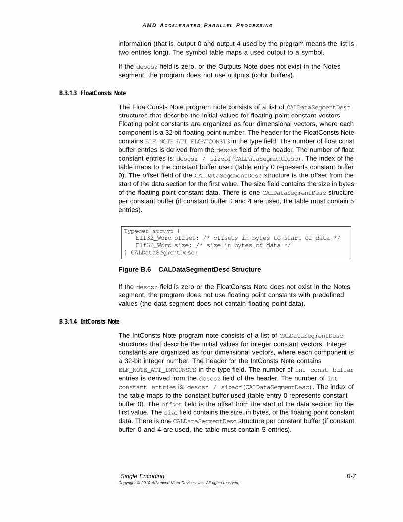
A M D A C C E L E R A T E D P A R A L L E L P R O C E S S I N G
Single Encoding B-7Copyright © 2010 Advanced Micro Devices, Inc. All rights reserved.
information (that is, output 0 and output 4 used by the program means the list is two entries long). The symbol table maps a used output to a symbol.
If the descsz field is zero, or the Outputs Note does not exist in the Notes segment, the program does not use outputs (color buffers).
B.3.1.3 FloatConsts Note
The FloatConsts Note program note consists of a list of CALDataSegmentDesc structures that describe the initial values for floating point constant vectors. Floating point constants are organized as four dimensional vectors, where each component is a 32-bit floating point number. The header for the FloatConsts Note contains ELF_NOTE_ATI_FLOATCONSTS in the type field. The number of float const buffer entries is derived from the descsz field of the header. The number of float constant entries is: descsz / sizeof(CALDataSegmentDesc). The index of the table maps to the constant buffer used (table entry 0 represents constant buffer 0). The offset field of the CALDataSegementDesc structure is the offset from the start of the data section for the first value. The size field contains the size in bytes of the floating point constant data. There is one CALDataSegmentDesc structure per constant buffer (if constant buffer 0 and 4 are used, the table must contain 5 entries).
Figure B.6 CALDataSegmentDesc Structure
If the descsz field is zero or the FloatConsts Note does not exist in the Notes segment, the program does not use floating point constants with predefined values (the data segment does not contain floating point data).
B.3.1.4 IntConsts Note
The IntConsts Note program note consists of a list of CALDataSegmentDesc structures that describe the initial values for integer constant vectors. Integer constants are organized as four dimensional vectors, where each component is a 32-bit integer number. The header for the IntConsts Note contains ELF_NOTE_ATI_INTCONSTS in the type field. The number of int const buffer entries is derived from the descsz field of the header. The number of int constant entries is: descsz / sizeof(CALDataSegmentDesc). The index of the table maps to the constant buffer used (table entry 0 represents constant buffer 0). The offset field is the offset from the start of the data section for the first value. The size field contains the size, in bytes, of the floating point constant data. There is one CALDataSegmentDesc structure per constant buffer (if constant buffer 0 and 4 are used, the table must contain 5 entries).
Typedef struct { Elf32_Word offset; /* offsets in bytes to start of data */ Elf32_Word size; /* size in bytes of data */
} CALDataSegmentDesc;
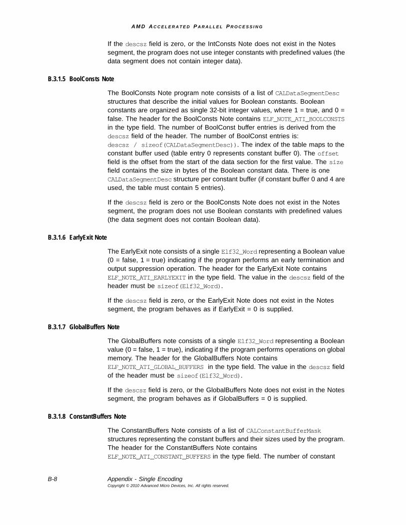
A M D A C C E L E R A T E D P A R A L L E L P R O C E S S I N G
B-8 Appendix - Single EncodingCopyright © 2010 Advanced Micro Devices, Inc. All rights reserved.
If the descsz field is zero, or the IntConsts Note does not exist in the Notes segment, the program does not use integer constants with predefined values (the data segment does not contain integer data).
B.3.1.5 BoolConsts Note
The BoolConsts Note program note consists of a list of CALDataSegmentDesc structures that describe the initial values for Boolean constants. Boolean constants are organized as single 32-bit integer values, where 1 = true, and 0 = false. The header for the BoolConsts Note contains ELF_NOTE_ATI_BOOLCONSTS in the type field. The number of BoolConst buffer entries is derived from the descsz field of the header. The number of BoolConst entries is: descsz / sizeof(CALDataSegmentDesc)). The index of the table maps to the constant buffer used (table entry 0 represents constant buffer 0). The offset field is the offset from the start of the data section for the first value. The size field contains the size in bytes of the Boolean constant data. There is one CALDataSegmentDesc structure per constant buffer (if constant buffer 0 and 4 are used, the table must contain 5 entries).
If the descsz field is zero or the BoolConsts Note does not exist in the Notes segment, the program does not use Boolean constants with predefined values (the data segment does not contain Boolean data).
B.3.1.6 EarlyExit Note
The EarlyExit note consists of a single Elf32_Word representing a Boolean value (0 = false, 1 = true) indicating if the program performs an early termination and output suppression operation. The header for the EarlyExit Note contains ELF_NOTE_ATI_EARLYEXIT in the type field. The value in the descsz field of the header must be sizeof(Elf32_Word).
If the descsz field is zero, or the EarlyExit Note does not exist in the Notes segment, the program behaves as if EarlyExit = 0 is supplied.
B.3.1.7 GlobalBuffers Note
The GlobalBuffers note consists of a single Elf32_Word representing a Boolean value (0 = false, 1 = true), indicating if the program performs operations on global memory. The header for the GlobalBuffers Note contains ELF_NOTE_ATI_GLOBAL_BUFFERS in the type field. The value in the descsz field of the header must be sizeof(Elf32_Word).
If the descsz field is zero, or the GlobalBuffers Note does not exist in the Notes segment, the program behaves as if GlobalBuffers = 0 is supplied.
B.3.1.8 ConstantBuffers Note
The ConstantBuffers Note consists of a list of CALConstantBufferMask structures representing the constant buffers and their sizes used by the program. The header for the ConstantBuffers Note contains ELF_NOTE_ATI_CONSTANT_BUFFERS in the type field. The number of constant
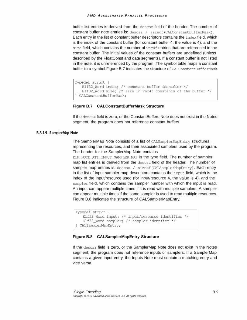
A M D A C C E L E R A T E D P A R A L L E L P R O C E S S I N G
Single Encoding B-9Copyright © 2010 Advanced Micro Devices, Inc. All rights reserved.
buffer list entries is derived from the descsz field of the header. The number of constant buffer note entries is: descsz / sizeof(CALConstantBufferMask). Each entry in the list of constant buffer descriptors contains the index field, which is the index of the constant buffer (for constant buffer 4, the value is 4), and the size field, which contains the number of vec4f entries that are referenced in the constant buffer. The initial values of the constant buffers are undefined (unless described by the FloatConst and data segments). If a constant buffer is not listed in the note, it is unreferenced by the program. The symbol table maps a constant buffer to a symbol.Figure B.7 indicates the structure of CALConstantBufferMask.
Figure B.7 CALConstantBufferMask Structure
If the descsz field is zero, or the ConstantBuffers Note does not exist in the Notes segment, the program does not reference constant buffers.
B.3.1.9 SamplerMap Note
The SamplerMap Note consists of a list of CALSamplerMapEntry structures, representing the resources, and their associated samplers used by the program. The header for the SamplerMap Note contains ELF_NOTE_ATI_INPUT_SAMPLER_MAP in the type field. The number of sampler map list entries is derived from the descsz field of the header. The number of sampler map entries is: descsz / sizeof(CALSamplerMapEntry). Each entry in the list of input sampler map descriptors contains the input field, which is the index of the input/resource used (for input/resource 4, the value is 4), and the sampler field, which contains the sampler number with which the input is read. An input can appear multiple times if it is read with multiple samplers. A sampler can appear multiple times if the same sampler is used to read multiple resources. Figure B.8 indicates the structure of CALSamplerMapEntry.
Figure B.8 CALSamplerMapEntry Structure
If the descsz field is zero, or the SamplerMap Note does not exist in the Notes segment, the program does not reference inputs or samplers. If a SamplerMap contains a given input entry, the Inputs Note must contain a matching entry and vice versa.
Typedef struct { Elf32_Word index; /* constant buffer identfier */ Elf32_Word size; /* size in vec4f constants of the buffer */
} CALConstantBufferMask;
Typedef struct { Elf32_Word input; /* input/resource identifier */ Elf32_Word sampler; /* sampler identfier */
} CALSamplerMapEntry;
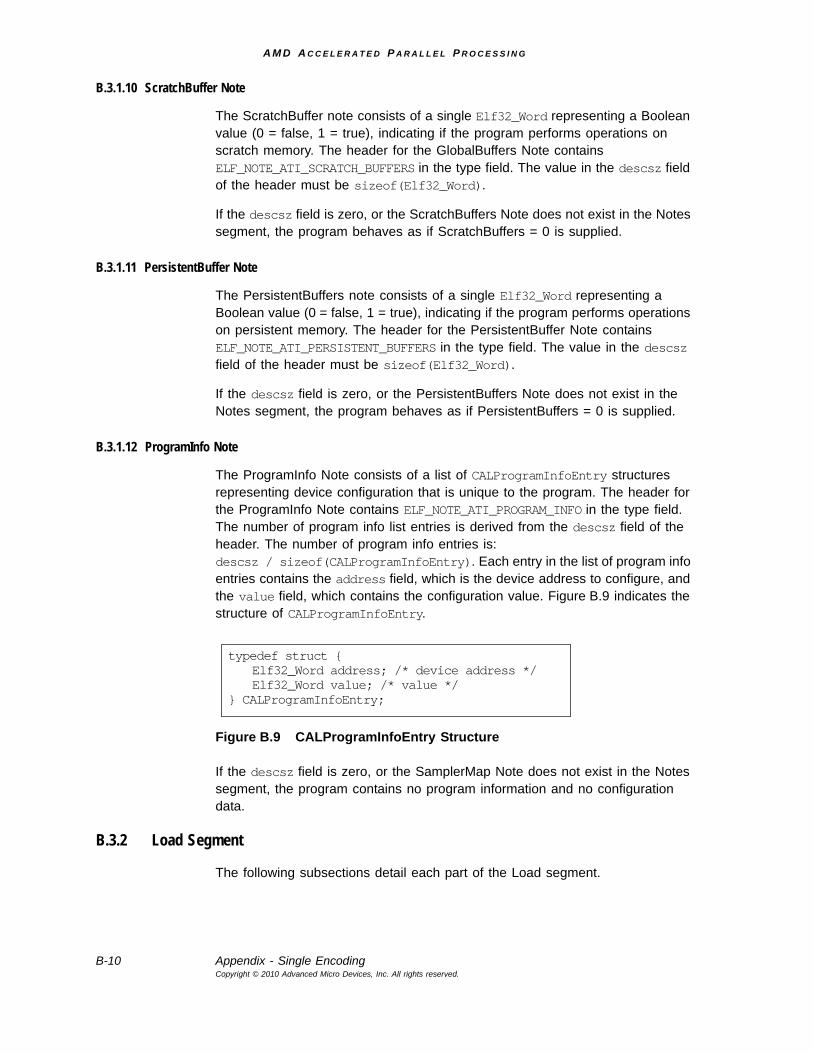
A M D A C C E L E R A T E D P A R A L L E L P R O C E S S I N G
B-10 Appendix - Single EncodingCopyright © 2010 Advanced Micro Devices, Inc. All rights reserved.
B.3.1.10 ScratchBuffer Note
The ScratchBuffer note consists of a single Elf32_Word representing a Boolean value (0 = false, 1 = true), indicating if the program performs operations on scratch memory. The header for the GlobalBuffers Note contains ELF_NOTE_ATI_SCRATCH_BUFFERS in the type field. The value in the descsz field of the header must be sizeof(Elf32_Word).
If the descsz field is zero, or the ScratchBuffers Note does not exist in the Notes segment, the program behaves as if ScratchBuffers = 0 is supplied.
B.3.1.11 PersistentBuffer Note
The PersistentBuffers note consists of a single Elf32_Word representing a Boolean value (0 = false, 1 = true), indicating if the program performs operations on persistent memory. The header for the PersistentBuffer Note contains ELF_NOTE_ATI_PERSISTENT_BUFFERS in the type field. The value in the descsz field of the header must be sizeof(Elf32_Word).
If the descsz field is zero, or the PersistentBuffers Note does not exist in the Notes segment, the program behaves as if PersistentBuffers = 0 is supplied.
B.3.1.12 ProgramInfo Note
The ProgramInfo Note consists of a list of CALProgramInfoEntry structures representing device configuration that is unique to the program. The header for the ProgramInfo Note contains ELF_NOTE_ATI_PROGRAM_INFO in the type field. The number of program info list entries is derived from the descsz field of the header. The number of program info entries is: descsz / sizeof(CALProgramInfoEntry). Each entry in the list of program info entries contains the address field, which is the device address to configure, and the value field, which contains the configuration value. Figure B.9 indicates the structure of CALProgramInfoEntry.
Figure B.9 CALProgramInfoEntry Structure
If the descsz field is zero, or the SamplerMap Note does not exist in the Notes segment, the program contains no program information and no configuration data.
B.3.2 Load Segment
The following subsections detail each part of the Load segment.
typedef struct { Elf32_Word address; /* device address */ Elf32_Word value; /* value */
} CALProgramInfoEntry;
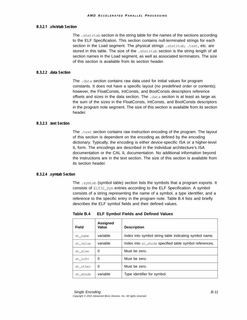
A M D A C C E L E R A T E D P A R A L L E L P R O C E S S I N G
Single Encoding B-11Copyright © 2010 Advanced Micro Devices, Inc. All rights reserved.
B.3.2.1 .shstrtab Section
The .shstrtab section is the string table for the names of the sections according to the ELF Specification. This section contains null-terminated strings for each section in the Load segment. The physical strings .shstrtab, .text, etc. are stored in this table. The size of the .shstrtab section is the string length of all section names in the Load segment, as well as associated terminators. The size of this section is available from its section header.
B.3.2.2 .data Section
The .data section contains raw data used for initial values for program constants. It does not have a specific layout (no predefined order or contents); however, the FloatConsts, IntConsts, and BoolConsts descriptors reference offsets and sizes in the data section. The .data section is at least as large as the sum of the sizes in the FloatConsts, IntConsts, and BoolConsts descriptors in the program note segment. The size of this section is available from its section header.
B.3.2.3 .text Section
The .text section contains raw instruction encoding of the program. The layout of this section is dependent on the encoding as defined by the encoding dictionary. Typically, the encoding is either device-specific ISA or a higher-level IL form. The encodings are described in the individual architecture’s ISA documentation or the CAL IL documentation. No additional information beyond the instructions are in the text section. The size of this section is available from its section header.
B.3.2.4 .symtab Section
The .symtab (symbol table) section lists the symbols that a program exports. It consists of Elf32_Sym entries according to the ELF Specification. A symbol consists of a string representing the name of a symbol, a type identifier, and a reference to the specific entry in the program note. Table B.4 lists and briefly describes the ELF symbol fields and their defined values.
Table B.4 ELF Symbol Fields and Defined Values
Field Assigned Value Description
st_name variable Index into symbol string table indicating symbol name.
st_value variable Index into st_shndx specified table symbol references.
st_size 0 Must be zero.
st_info 0 Must be zero.
st_other 0 Must be zero.
st_shndx variable Type identifier for symbol.
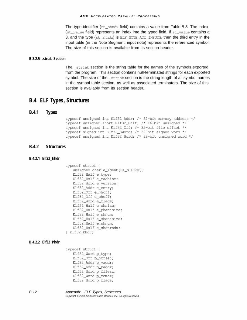
A M D A C C E L E R A T E D P A R A L L E L P R O C E S S I N G
B-12 Appendix - ELF Types, StructuresCopyright © 2010 Advanced Micro Devices, Inc. All rights reserved.
The type identifier (st_shndx field) contains a value from Table B.3. The index (st_value field) represents an index into the typed field. If st_value contains a 3, and the type (st_shndx) is ELF_NOTE_ATI_INPUTS, then the third entry in the input table (in the Note Segment, input note) represents the referenced symbol. The size of this section is available from its section header.
B.3.2.5 .strtab Section
The .strtab section is the string table for the names of the symbols exported from the program. This section contains null-terminated strings for each exported symbol. The size of the .strtab section is the string length of all symbol names in the symbol table section, as well as associated terminators. The size of this section is available from its section header.
B.4 ELF Types, Structures
B.4.1 Typestypedef unsigned int Elf32_Addr; /* 32-bit memory address */ typedef unsigned short Elf32_Half; /* 16-bit unsigned */ typedef unsigned int Elf32_Off; /* 32-bit file offset */ typedef signed int Elf32_Sword; /* 32-bit signed word */ typedef unsigned int Elf32_Word; /* 32-bit unsigned word */
B.4.2 Structures
B.4.2.1 Elf32_Ehdrtypedef struct {
unsigned char e_ident[EI_NIDENT]; Elf32_Half e_type; Elf32_Half e_machine; Elf32_Word e_version; Elf32_Addr e_entry; Elf32_Off e_phoff; Elf32_Off e_shoff; Elf32_Word e_flags; Elf32_Half e_ehsize; Elf32_Half e_phentsize; Elf32_Half e_phnum; Elf32_Half e_shentsize; Elf32_Half e_shnum; Elf32_Half e_shstrndx;
} Elf32_Ehdr;
B.4.2.2 Elf32_Phdrtypedef struct {
Elf32_Word p_type; Elf32_Off p_offset; Elf32_Addr p_vaddr; Elf32_Addr p_paddr; Elf32_Word p_filesz; Elf32_Word p_memsz; Elf32_Word p_flags;
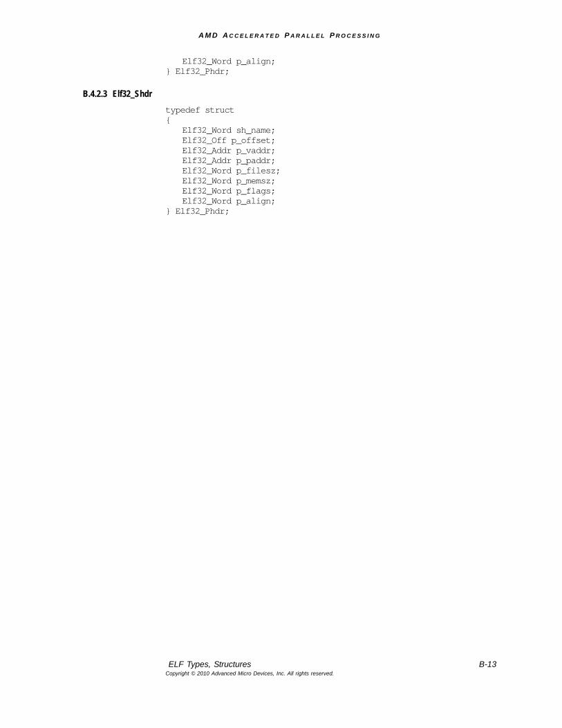
A M D A C C E L E R A T E D P A R A L L E L P R O C E S S I N G
ELF Types, Structures B-13Copyright © 2010 Advanced Micro Devices, Inc. All rights reserved.
Elf32_Word p_align; } Elf32_Phdr;
B.4.2.3 Elf32_Shdrtypedef struct {
Elf32_Word sh_name; Elf32_Off p_offset; Elf32_Addr p_vaddr; Elf32_Addr p_paddr; Elf32_Word p_filesz; Elf32_Word p_memsz; Elf32_Word p_flags; Elf32_Word p_align;
} Elf32_Phdr;
A M D A C C E L E R A T E D P A R A L L E L P R O C E S S I N G
B-14 Appendix - ELF Types, StructuresCopyright © 2010 Advanced Micro Devices, Inc. All rights reserved.
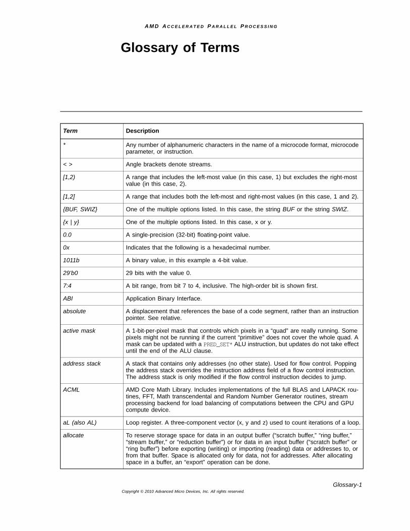
A M D A C C E L E R A T E D P A R A L L E L P R O C E S S I N G
Glossary-1Copyright © 2010 Advanced Micro Devices, Inc. All rights reserved.
Glossary of Terms
Term Description
* Any number of alphanumeric characters in the name of a microcode format, microcode parameter, or instruction.
< > Angle brackets denote streams.
[1,2) A range that includes the left-most value (in this case, 1) but excludes the right-most value (in this case, 2).
[1,2] A range that includes both the left-most and right-most values (in this case, 1 and 2).
{BUF, SWIZ} One of the multiple options listed. In this case, the string BUF or the string SWIZ.
{x | y} One of the multiple options listed. In this case, x or y.
0.0 A single-precision (32-bit) floating-point value.
0x Indicates that the following is a hexadecimal number.
1011b A binary value, in this example a 4-bit value.
29’b0 29 bits with the value 0.
7:4 A bit range, from bit 7 to 4, inclusive. The high-order bit is shown first.
ABI Application Binary Interface.
absolute A displacement that references the base of a code segment, rather than an instruction pointer. See relative.
active mask A 1-bit-per-pixel mask that controls which pixels in a “quad” are really running. Some pixels might not be running if the current “primitive” does not cover the whole quad. A mask can be updated with a PRED_SET* ALU instruction, but updates do not take effect until the end of the ALU clause.
address stack A stack that contains only addresses (no other state). Used for flow control. Popping the address stack overrides the instruction address field of a flow control instruction. The address stack is only modified if the flow control instruction decides to jump.
ACML AMD Core Math Library. Includes implementations of the full BLAS and LAPACK rou-tines, FFT, Math transcendental and Random Number Generator routines, stream processing backend for load balancing of computations between the CPU and GPU compute device.
aL (also AL) Loop register. A three-component vector (x, y and z) used to count iterations of a loop.
allocate To reserve storage space for data in an output buffer (“scratch buffer,” “ring buffer,” “stream buffer,” or “reduction buffer”) or for data in an input buffer (“scratch buffer” or “ring buffer”) before exporting (writing) or importing (reading) data or addresses to, or from that buffer. Space is allocated only for data, not for addresses. After allocating space in a buffer, an “export” operation can be done.
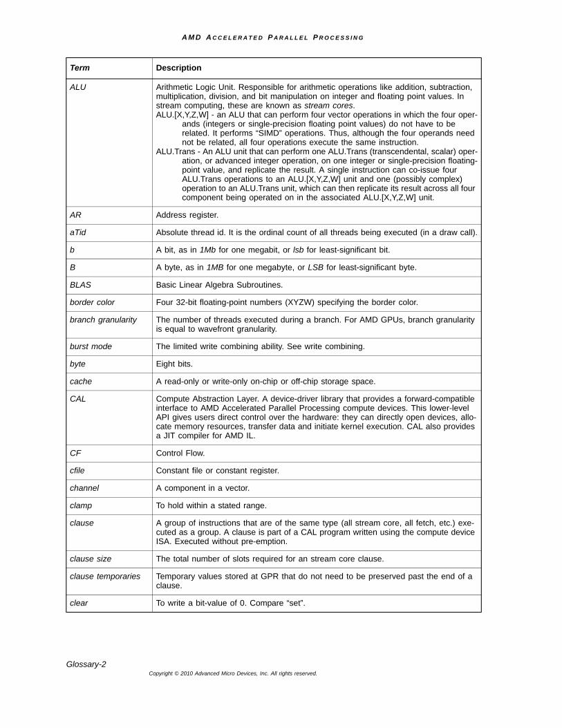
A M D A C C E L E R A T E D P A R A L L E L P R O C E S S I N G
Glossary-2Copyright © 2010 Advanced Micro Devices, Inc. All rights reserved.
ALU Arithmetic Logic Unit. Responsible for arithmetic operations like addition, subtraction, multiplication, division, and bit manipulation on integer and floating point values. In stream computing, these are known as stream cores.ALU.[X,Y,Z,W] - an ALU that can perform four vector operations in which the four oper-
ands (integers or single-precision floating point values) do not have to be related. It performs “SIMD” operations. Thus, although the four operands need not be related, all four operations execute the same instruction.
ALU.Trans - An ALU unit that can perform one ALU.Trans (transcendental, scalar) oper-ation, or advanced integer operation, on one integer or single-precision floating-point value, and replicate the result. A single instruction can co-issue four ALU.Trans operations to an ALU.[X,Y,Z,W] unit and one (possibly complex) operation to an ALU.Trans unit, which can then replicate its result across all four component being operated on in the associated ALU.[X,Y,Z,W] unit.
AR Address register.
aTid Absolute thread id. It is the ordinal count of all threads being executed (in a draw call).
b A bit, as in 1Mb for one megabit, or lsb for least-significant bit.
B A byte, as in 1MB for one megabyte, or LSB for least-significant byte.
BLAS Basic Linear Algebra Subroutines.
border color Four 32-bit floating-point numbers (XYZW) specifying the border color.
branch granularity The number of threads executed during a branch. For AMD GPUs, branch granularity is equal to wavefront granularity.
burst mode The limited write combining ability. See write combining.
byte Eight bits.
cache A read-only or write-only on-chip or off-chip storage space.
CAL Compute Abstraction Layer. A device-driver library that provides a forward-compatible interface to AMD Accelerated Parallel Processing compute devices. This lower-level API gives users direct control over the hardware: they can directly open devices, allo-cate memory resources, transfer data and initiate kernel execution. CAL also provides a JIT compiler for AMD IL.
CF Control Flow.
cfile Constant file or constant register.
channel A component in a vector.
clamp To hold within a stated range.
clause A group of instructions that are of the same type (all stream core, all fetch, etc.) exe-cuted as a group. A clause is part of a CAL program written using the compute device ISA. Executed without pre-emption.
clause size The total number of slots required for an stream core clause.
clause temporaries Temporary values stored at GPR that do not need to be preserved past the end of a clause.
clear To write a bit-value of 0. Compare “set”.
Term Description
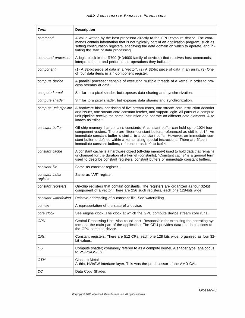
A M D A C C E L E R A T E D P A R A L L E L P R O C E S S I N G
Glossary-3Copyright © 2010 Advanced Micro Devices, Inc. All rights reserved.
command A value written by the host processor directly to the GPU compute device. The com-mands contain information that is not typically part of an application program, such as setting configuration registers, specifying the data domain on which to operate, and ini-tiating the start of data processing.
command processor A logic block in the R700 (HD4000-family of devices) that receives host commands, interprets them, and performs the operations they indicate.
component (1) A 32-bit piece of data in a “vector”. (2) A 32-bit piece of data in an array. (3) One of four data items in a 4-component register.
compute device A parallel processor capable of executing multiple threads of a kernel in order to pro-cess streams of data.
compute kernel Similar to a pixel shader, but exposes data sharing and synchronization.
compute shader Similar to a pixel shader, but exposes data sharing and synchronization.
compute unit pipeline A hardware block consisting of five stream cores, one stream core instruction decoder and issuer, one stream core constant fetcher, and support logic. All parts of a compute unit pipeline receive the same instruction and operate on different data elements. Also known as “slice.”
constant buffer Off-chip memory that contains constants. A constant buffer can hold up to 1024 four-component vectors. There are fifteen constant buffers, referenced as cb0 to cb14. An immediate constant buffer is similar to a constant buffer. However, an immediate con-stant buffer is defined within a kernel using special instructions. There are fifteen immediate constant buffers, referenced as icb0 to icb14.
constant cache A constant cache is a hardware object (off-chip memory) used to hold data that remains unchanged for the duration of a kernel (constants). “Constant cache” is a general term used to describe constant registers, constant buffers or immediate constant buffers.
constant file Same as constant register.
constant index register
Same as “AR” register.
constant registers On-chip registers that contain constants. The registers are organized as four 32-bit component of a vector. There are 256 such registers, each one 128-bits wide.
constant waterfalling Relative addressing of a constant file. See waterfalling.
context A representation of the state of a device.
core clock See engine clock. The clock at which the GPU compute device stream core runs.
CPU Central Processing Unit. Also called host. Responsible for executing the operating sys-tem and the main part of the application. The CPU provides data and instructions to the GPU compute device.
CRs Constant registers. There are 512 CRs, each one 128 bits wide, organized as four 32-bit values.
CS Compute shader; commonly refered to as a compute kernel. A shader type, analogous to VS/PS/GS/ES.
CTM Close-to-Metal. A thin, HW/SW interface layer. This was the predecessor of the AMD CAL.
DC Data Copy Shader.
Term Description
A M D A C C E L E R A T E D P A R A L L E L P R O C E S S I N G
Glossary-4Copyright © 2010 Advanced Micro Devices, Inc. All rights reserved.
device A device is an entire AMD Accelerated Parallel Processing compute device.
DMA Direct-memory access. Also called DMA engine. Responsible for independently trans-ferring data to, and from, the GPU compute device’s local memory. This allows other computations to occur in parallel, increasing overall system performance.
double word Dword. Two words, or four bytes, or 32 bits.
double quad word Eight words, or 16 bytes, or 128 bits. Also called “octword.”
domain of execution A specified rectangular region of the output buffer to which threads are mapped.
DPP Data-Parallel Processor.
dst.X The X “slot” of an destination operand.
dword Double word. Two words, or four bytes, or 32 bits.
element A component in a vector.
engine clock The clock driving the stream core and memory fetch units on the GPU compute device.
enum(7) A seven-bit field that specifies an enumerated set of decimal values (in this case, a set of up to 27 values). The valid values can begin at a value greater than, or equal to, zero; and the number of valid values can be less than, or equal to, the maximum sup-ported by the field.
event A token sent through a pipeline that can be used to enforce synchronization, flush caches, and report status back to the host application.
export To write data from GPRs to an output buffer (scratch, ring, stream, frame or global buffer, or to a register), or to read data from an input buffer (a “scratch buffer” or “ring buffer”) to GPRs. The term “export” is a partial misnomer because it performs both input and output functions. Prior to exporting, an allocation operation must be performed to reserve space in the associated buffer.
FC Flow control.
FFT Fast Fourier Transform.
flag A bit that is modified by a CF or stream core operation and that can affect subsequent operations.
FLOP Floating Point Operation.
flush To writeback and invalidate cache data.
FMA Fused multiply add.
frame A single two-dimensional screenful of data, or the storage space required for it.
frame buffer Off-chip memory that stores a frame. Sometimes refers to the all of the GPU memory (excluding local memory and caches).
FS Fetch subroutine. A global program for fetching vertex data. It can be called by a “vertex shader” (VS), and it runs in the same thread context as the vertex program, and thus is treated for execution purposes as part of the vertex program. The FS provides driver independence between the process of fetching data required by a VS, and the VS itself. This includes having a semantic connection between the outputs of the fetch process and the inputs of the VS.
Term Description
A M D A C C E L E R A T E D P A R A L L E L P R O C E S S I N G
Glossary-5Copyright © 2010 Advanced Micro Devices, Inc. All rights reserved.
function A subprogram called by the main program or another function within an AMD IL stream. Functions are delineated by FUNC and ENDFUNC.
gather Reading from arbitrary memory locations by a thread.
gather stream Input streams are treated as a memory array, and data elements are addressed directly.
global buffer GPU memory space containing the arbitrary address locations to which uncached ker-nel outputs are written. Can be read either cached or uncached. When read in uncached mode, it is known as mem-import. Allows applications the flexibility to read from and write to arbitrary locations in input buffers and output buffers, respectively.
global memory Memory for reads/writes between threads. On ATI Radeon™ HD 5XXX series devices and later, atomic operations can be used to synchronize memory operations.
GPGPU General-purpose compute device. A GPU compute device that performs general-pur-pose calculations.
GPR General-purpose register. GPRs hold vectors of either four 32-bit IEEE floating-point, or four 8-, 16-, or 32-bit signed or unsigned integer or two 64-bit IEEE double precision data components (values). These registers can be indexed, and consist of an on-chip part and an off-chip part, called the “scratch buffer,” in memory.
GPU Graphics Processing Unit. An integrated circuit that renders and displays graphical images on a monitor. Also called Graphics Hardware, Compute Device, and Data Par-allel Processor.
GPU engine clock frequency
Also called 3D engine speed.
GPU compute device A parallel processor capable of executing multiple threads of a kernel in order to pro-cess streams of data.
GS Geometry Shader.
HAL Hardware Abstraction Layer.
host Also called CPU.
iff If and only if.
IL Intermediate Language. In this manual, the AMD version: AMD IL. A pseudo-assembly language that can be used to describe kernels for GPU compute devices. AMD IL is designed for efficient generalization of GPU compute device instructions so that pro-grams can run on a variety of platforms without having to be rewritten for each platform.
in flight A thread currently being processed.
instruction A computing function specified by the code field of an IL_OpCode token. Compare “opcode”, “operation”, and “instruction packet”.
instruction packet A group of tokens starting with an IL_OpCode token that represent a single AMD IL instruction.
int(2) A 2-bit field that specifies an integer value.
ISA Instruction Set Architecture. The complete specification of the interface between com-puter programs and the underlying computer hardware.
kcache A memory area containing “waterfall” (off-chip) constants. The cache lines of these con-stants can be locked. The “constant registers” are the 256 on-chip constants.
Term Description
A M D A C C E L E R A T E D P A R A L L E L P R O C E S S I N G
Glossary-6Copyright © 2010 Advanced Micro Devices, Inc. All rights reserved.
kernel A user-developed program that is run repeatedly on a stream of data. A parallel function that operates on every element of input streams. A device program is one type of ker-nel. Unless otherwise specified, an AMD Accelerated Parallel Processing compute device program is a kernel composed of a main program and zero or more functions. Also called Shader Program. This is not to be confused with an OS kernel, which con-trols hardware.
LAPACK Linear Algebra Package.
LDS Local Data Share. Part of local memory. These are read/write registers that support sharing between all threads in a group. Synchronization is required.
LERP Linear Interpolation.
local memory fetch units
Dedicated hardware that a) processes fetch instructions, b) requests data from the memory controller, and c) loads registers with data returned from the cache. They are run at stream core or engine clock speeds. Formerly called texture units.
LOD Level Of Detail.
loop index A register initialized by software and incremented by hardware on each iteration of a loop.
lsb Least-significant bit.
LSB Least-significant byte.
MAD Multiply-Add. A fused instruction that both multiplies and adds.
mask (1) To prevent from being seen or acted upon. (2) A field of bits used for a control purpose.
MBZ Must be zero.
mem-export An AMD IL term random writes to the global buffer.
mem-import Uncached reads from the global buffer.
memory clock The clock driving the memory chips on the GPU compute device.
microcode format An encoding format whose fields specify instructions and associated parameters. Micro-code formats are used in sets of two or four. For example, the two mnemonics, CF_DWORD[0,1] indicate a microcode-format pair, CF_DWORD0 and CF_DWORD1.
MIMD Multiple Instruction Multiple Data.– Multiple SIMD units operating in parallel (Multi-Processor System) – Distributed or shared memory
MRT Multiple Render Target. One of multiple areas of local GPU compute device memory, such as a “frame buffer”, to which a graphics pipeline writes data.
MSAA Multi-Sample Anti-Aliasing.
msb Most-significant bit.
MSB Most-significant byte.
neighborhood A group of four threads in the same wavefront that have consecutive thread IDs (Tid). The first Tid must be a multiple of four. For example, threads with Tid = 0, 1, 2, and 3 form a neighborhood, as do threads with Tid = 12, 13, 14, and 15.
Term Description
A M D A C C E L E R A T E D P A R A L L E L P R O C E S S I N G
Glossary-7Copyright © 2010 Advanced Micro Devices, Inc. All rights reserved.
normalized A numeric value in the range [a, b] that has been converted to a range of 0.0 to 1.0 using the formula: normalized value = value/ (b–a+ 1)
oct word Eight words, or 16 bytes, or 128 bits. Same as “double quad word”. Also referred to as octa word.
opcode The numeric value of the code field of an “instruction”. For example, the opcode for the CMOV instruction is decimal 16 (0x10).
opcode token A 32-bit value that describes the operation of an instruction.
operation The function performed by an “instruction”.
PaC Parameter Cache.
PCI Express A high-speed computer expansion card interface used by modern graphics cards, GPU compute devices and other peripherals needing high data transfer rates. Unlike previ-ous expansion interfaces, PCI Express is structured around point-to-point links. Also called PCIe.
PoC Position Cache.
pop Write “stack” entries to their associated hardware-maintained control-flow state. The POP_COUNT field of the CF_DWORD1 microcode format specifies the number of stack entries to pop for instructions that pop the stack. Compare “push.”
pre-emption The act of temporarily interrupting a task being carried out on a computer system, with-out requiring its cooperation, with the intention of resuming the task at a later time.
processor Unless otherwise stated, the AMD Accelerated Parallel Processing compute device.
program Unless otherwise specified, a program is a set of instructions that can run on the AMD Accelerated Parallel Processing compute device. A device program is a type of kernel.
PS Pixel Shader, aka pixel kernel.
push Read hardware-maintained control-flow state and write their contents onto the stack. Compare pop.
PV Previous vector register. It contains the previous four-component vector result from a ALU.[X,Y,Z,W] unit within a given clause.
quad For a compute kernel, this consists of four consecutive work-items. For pixel and other shaders, this is a group of 2x2 threads in the NDRange. Always processed together.
rasterization The process of mapping threads from the domain of execution to the SIMD engine. This term is a carryover from graphics, where it refers to the process of turning geometry, such as triangles, into pixels.
rasterization order The order of the thread mapping generated by rasterization.
RAT Random Access Target. Same as UAV. Allows, on DX11 hardware, writes to, and reads from, any arbitrary location in a buffer.
RB Ring Buffer.
register For a GPU, this is a 128-bit address mapped memory space consisting of four 32-bit components.
relative Referencing with a displacement (also called offset) from an index register or the loop index, rather than from the base address of a program (the first control flow [CF] instruction).
Term Description
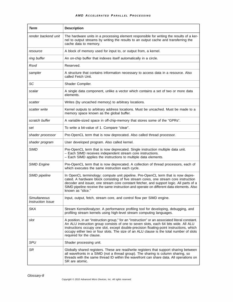
A M D A C C E L E R A T E D P A R A L L E L P R O C E S S I N G
Glossary-8Copyright © 2010 Advanced Micro Devices, Inc. All rights reserved.
render backend unit The hardware units in a processing element responsible for writing the results of a ker-nel to output streams by writing the results to an output cache and transferring the cache data to memory.
resource A block of memory used for input to, or output from, a kernel.
ring buffer An on-chip buffer that indexes itself automatically in a circle.
Rsvd Reserved.
sampler A structure that contains information necessary to access data in a resource. Also called Fetch Unit.
SC Shader Compiler.
scalar A single data component, unlike a vector which contains a set of two or more data elements.
scatter Writes (by uncached memory) to arbitrary locations.
scatter write Kernel outputs to arbitrary address locations. Must be uncached. Must be made to a memory space known as the global buffer.
scratch buffer A variable-sized space in off-chip-memory that stores some of the “GPRs”.
set To write a bit-value of 1. Compare “clear”.
shader processor Pre-OpenCL term that is now deprecated. Also called thread processor.
shader program User developed program. Also called kernel.
SIMD Pre-OpenCL term that is now deprecated. Single instruction multiple data unit.– Each SIMD receives independent stream core instructions.– Each SIMD applies the instructions to multiple data elements.
SIMD Engine Pre-OpenCL term that is now deprecated. A collection of thread processors, each of which executes the same instruction each cycle.
SIMD pipeline In OpenCL terminology: compute unit pipeline. Pre-OpenCL term that is now depre-cated. A hardware block consisting of five stream cores, one stream core instruction decoder and issuer, one stream core constant fetcher, and support logic. All parts of a SIMD pipeline receive the same instruction and operate on different data elements. Also known as “slice.”
Simultaneous Instruction Issue
Input, output, fetch, stream core, and control flow per SIMD engine.
SKA Stream KernelAnalyzer. A performance profiling tool for developing, debugging, and profiling stream kernels using high-level stream computing languages.
slot A position, in an “instruction group,” for an “instruction” or an associated literal constant. An ALU instruction group consists of one to seven slots, each 64 bits wide. All ALU instructions occupy one slot, except double-precision floating-point instructions, which occupy either two or four slots. The size of an ALU clause is the total number of slots required for the clause.
SPU Shader processing unit.
SR Globally shared registers. These are read/write registers that support sharing between all wavefronts in a SIMD (not a thread group). The sharing is column sharing, so threads with the same thread ID within the wavefront can share data. All operations on SR are atomic.
Term Description
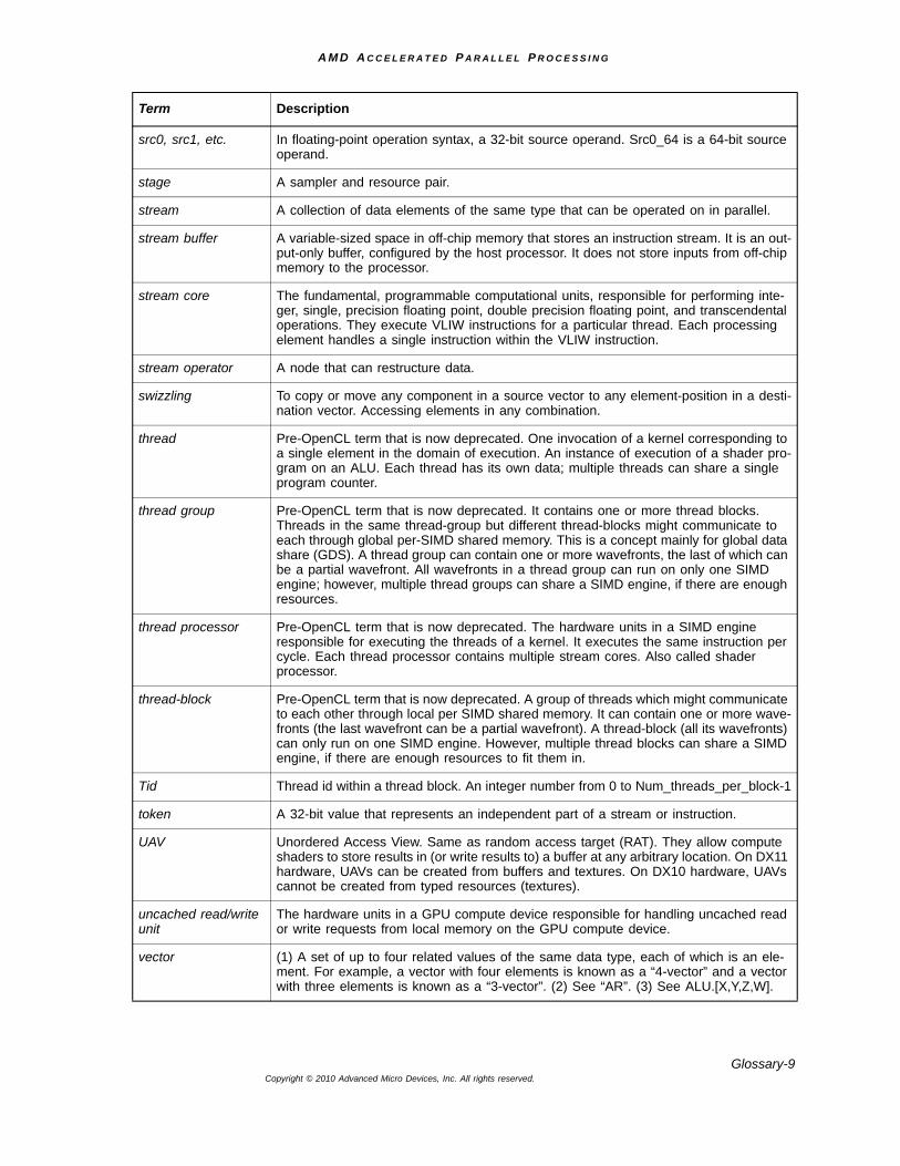
A M D A C C E L E R A T E D P A R A L L E L P R O C E S S I N G
Glossary-9Copyright © 2010 Advanced Micro Devices, Inc. All rights reserved.
src0, src1, etc. In floating-point operation syntax, a 32-bit source operand. Src0_64 is a 64-bit source operand.
stage A sampler and resource pair.
stream A collection of data elements of the same type that can be operated on in parallel.
stream buffer A variable-sized space in off-chip memory that stores an instruction stream. It is an out-put-only buffer, configured by the host processor. It does not store inputs from off-chip memory to the processor.
stream core The fundamental, programmable computational units, responsible for performing inte-ger, single, precision floating point, double precision floating point, and transcendental operations. They execute VLIW instructions for a particular thread. Each processing element handles a single instruction within the VLIW instruction.
stream operator A node that can restructure data.
swizzling To copy or move any component in a source vector to any element-position in a desti-nation vector. Accessing elements in any combination.
thread Pre-OpenCL term that is now deprecated. One invocation of a kernel corresponding to a single element in the domain of execution. An instance of execution of a shader pro-gram on an ALU. Each thread has its own data; multiple threads can share a single program counter.
thread group Pre-OpenCL term that is now deprecated. It contains one or more thread blocks. Threads in the same thread-group but different thread-blocks might communicate to each through global per-SIMD shared memory. This is a concept mainly for global data share (GDS). A thread group can contain one or more wavefronts, the last of which can be a partial wavefront. All wavefronts in a thread group can run on only one SIMD engine; however, multiple thread groups can share a SIMD engine, if there are enough resources.
thread processor Pre-OpenCL term that is now deprecated. The hardware units in a SIMD engine responsible for executing the threads of a kernel. It executes the same instruction per cycle. Each thread processor contains multiple stream cores. Also called shader processor.
thread-block Pre-OpenCL term that is now deprecated. A group of threads which might communicate to each other through local per SIMD shared memory. It can contain one or more wave-fronts (the last wavefront can be a partial wavefront). A thread-block (all its wavefronts) can only run on one SIMD engine. However, multiple thread blocks can share a SIMD engine, if there are enough resources to fit them in.
Tid Thread id within a thread block. An integer number from 0 to Num_threads_per_block-1
token A 32-bit value that represents an independent part of a stream or instruction.
UAV Unordered Access View. Same as random access target (RAT). They allow compute shaders to store results in (or write results to) a buffer at any arbitrary location. On DX11 hardware, UAVs can be created from buffers and textures. On DX10 hardware, UAVs cannot be created from typed resources (textures).
uncached read/write unit
The hardware units in a GPU compute device responsible for handling uncached read or write requests from local memory on the GPU compute device.
vector (1) A set of up to four related values of the same data type, each of which is an ele-ment. For example, a vector with four elements is known as a “4-vector” and a vector with three elements is known as a “3-vector”. (2) See “AR”. (3) See ALU.[X,Y,Z,W].
Term Description
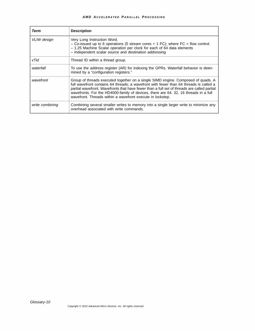
A M D A C C E L E R A T E D P A R A L L E L P R O C E S S I N G
Glossary-10Copyright © 2010 Advanced Micro Devices, Inc. All rights reserved.
VLIW design Very Long Instruction Word.– Co-issued up to 6 operations (5 stream cores + 1 FC); where FC = flow control.– 1.25 Machine Scalar operation per clock for each of 64 data elements– Independent scalar source and destination addressing
vTid Thread ID within a thread group.
waterfall To use the address register (AR) for indexing the GPRs. Waterfall behavior is deter-mined by a “configuration registers.”
wavefront Group of threads executed together on a single SIMD engine. Composed of quads. A full wavefront contains 64 threads; a wavefront with fewer than 64 threads is called a partial wavefront. Wavefronts that have fewer than a full set of threads are called partial wavefronts. For the HD4000-family of devices, there are 64. 32, 16 threads in a full wavefront. Threads within a wavefront execute in lockstep.
write combining Combining several smaller writes to memory into a single larger write to minimize any overhead associated with write commands.
Term Description
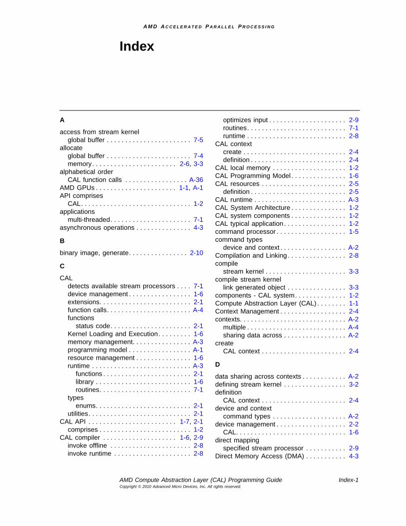
A M D A C C E L E R A T E D P A R A L L E L P R O C E S S I N G
AMD Compute Abstraction Layer (CAL) Programming Guide Index-1Copyright © 2010 Advanced Micro Devices, Inc. All rights reserved.
Index
A
access from stream kernelglobal buffer . . . . . . . . . . . . . . . . . . . . . . . 7-5
allocateglobal buffer . . . . . . . . . . . . . . . . . . . . . . . 7-4memory. . . . . . . . . . . . . . . . . . . . . . . 2-6, 3-3
alphabetical orderCAL function calls . . . . . . . . . . . . . . . . . A-36
AMD GPUs . . . . . . . . . . . . . . . . . . . . . . 1-1, A-1API comprises
CAL. . . . . . . . . . . . . . . . . . . . . . . . . . . . . . 1-2applications
multi-threaded. . . . . . . . . . . . . . . . . . . . . . 7-1asynchronous operations . . . . . . . . . . . . . . . 4-3
B
binary image, generate. . . . . . . . . . . . . . . . 2-10
C
CALdetects available stream processors . . . . 7-1device management . . . . . . . . . . . . . . . . . 1-6extensions. . . . . . . . . . . . . . . . . . . . . . . . . 2-1function calls. . . . . . . . . . . . . . . . . . . . . . . A-4functions
status code. . . . . . . . . . . . . . . . . . . . . . 2-1Kernel Loading and Execution. . . . . . . . . 1-6memory management. . . . . . . . . . . . . . . . A-3programming model . . . . . . . . . . . . . . . . . A-1resource management . . . . . . . . . . . . . . . 1-6runtime . . . . . . . . . . . . . . . . . . . . . . . . . . . A-3
functions . . . . . . . . . . . . . . . . . . . . . . . . 2-1library . . . . . . . . . . . . . . . . . . . . . . . . . . 1-6routines. . . . . . . . . . . . . . . . . . . . . . . . . 7-1
typesenums. . . . . . . . . . . . . . . . . . . . . . . . . . 2-1
utilities. . . . . . . . . . . . . . . . . . . . . . . . . . . . 2-1CAL API . . . . . . . . . . . . . . . . . . . . . . . . 1-7, 2-1
comprises . . . . . . . . . . . . . . . . . . . . . . . . . 1-2CAL compiler . . . . . . . . . . . . . . . . . . . . 1-6, 2-9
invoke offline . . . . . . . . . . . . . . . . . . . . . . 2-8invoke runtime . . . . . . . . . . . . . . . . . . . . . 2-8
optimizes input . . . . . . . . . . . . . . . . . . . . . 2-9routines. . . . . . . . . . . . . . . . . . . . . . . . . . . 7-1runtime . . . . . . . . . . . . . . . . . . . . . . . . . . . 2-8
CAL contextcreate . . . . . . . . . . . . . . . . . . . . . . . . . . . . 2-4definition . . . . . . . . . . . . . . . . . . . . . . . . . . 2-4
CAL local memory . . . . . . . . . . . . . . . . . . . . 1-2CAL Programming Model . . . . . . . . . . . . . . . 1-6CAL resources . . . . . . . . . . . . . . . . . . . . . . . 2-5
definition . . . . . . . . . . . . . . . . . . . . . . . . . . 2-5CAL runtime . . . . . . . . . . . . . . . . . . . . . . . . . A-3CAL System Architecture . . . . . . . . . . . . . . . 1-2CAL system components . . . . . . . . . . . . . . . 1-2CAL typical application . . . . . . . . . . . . . . . . . 1-2command processor . . . . . . . . . . . . . . . . . . . 1-5command types
device and context . . . . . . . . . . . . . . . . . . A-2Compilation and Linking . . . . . . . . . . . . . . . . 2-8compile
stream kernel . . . . . . . . . . . . . . . . . . . . . . 3-3compile stream kernel
link generated object . . . . . . . . . . . . . . . . 3-3components - CAL system. . . . . . . . . . . . . . 1-2Compute Abstraction Layer (CAL) . . . . . . . . 1-1Context Management . . . . . . . . . . . . . . . . . . 2-4contexts. . . . . . . . . . . . . . . . . . . . . . . . . . . . . A-2
multiple . . . . . . . . . . . . . . . . . . . . . . . . . . . A-4sharing data across . . . . . . . . . . . . . . . . . A-2
createCAL context . . . . . . . . . . . . . . . . . . . . . . . 2-4
D
data sharing across contexts . . . . . . . . . . . . A-2defining stream kernel . . . . . . . . . . . . . . . . . 3-2definition
CAL context . . . . . . . . . . . . . . . . . . . . . . . 2-4device and context
command types . . . . . . . . . . . . . . . . . . . . A-2device management . . . . . . . . . . . . . . . . . . . 2-2
CAL. . . . . . . . . . . . . . . . . . . . . . . . . . . . . . 1-6direct mapping
specified stream processor . . . . . . . . . . . 2-9Direct Memory Access (DMA) . . . . . . . . . . . 4-3
A M D A C C E L E R A T E D P A R A L L E L P R O C E S S I N G
Index-2Copyright © 2010 Advanced Micro Devices, Inc. All rights reserved.
DMA. . . . . . . . . . . . . . . . . . . . . . . . . . . . . . . . 4-3calls . . . . . . . . . . . . . . . . . . . . . . . . . . . . . . 4-4engine . . . . . . . . . . . . . . . . . . . . . . . . . . . . 4-4transfers . . . . . . . . . . . . . . . . . . . . . . . . . . 4-4
domain of execution . . . . . . . . . . . . . . . . . . 2-11double-precision arithmetic . . . . . . . . . . . . . . 7-6
E
enums . . . . . . . . . . . . . . . . . . . . . . . . . . . . . . 2-6CAL types . . . . . . . . . . . . . . . . . . . . . . . . . 2-1
executekernel . . . . . . . . . . . . . . . . . . . . . . . . . . . . 3-5stream kernel . . . . . . . . . . . . . . . . . . . . . . 3-4
F
function callsalphabetical order . . . . . . . . . . . . . . . . . A-36CAL . . . . . . . . . . . . . . . . . . . . . . . . . . . . . A-4
G
generatebinary image . . . . . . . . . . . . . . . . . . . . . . 2-10
global buffer . . . . . . . . . . . . . . . . . . . . . . . . . 7-4access from stream kernel . . . . . . . . . . . . 7-5allocate . . . . . . . . . . . . . . . . . . . . . . . . . . . 7-4parameter designation . . . . . . . . . . . . . . 2-11using CAL . . . . . . . . . . . . . . . . . . . . . . . . . 7-4
H
high-level kerneldevelopment . . . . . . . . . . . . . . . . . . . . . . 2-10languages . . . . . . . . . . . . . . . . . . . . . . . . 2-10
host commands. . . . . . . . . . . . . . . . . . . . . . . 1-5
I
Infrastructural Code. . . . . . . . . . . . . . . . . . . . 3-1input
optimizes . . . . . . . . . . . . . . . . . . . . . . . . . . 2-9input buffer
parameter designation . . . . . . . . . . . . . . 2-11input resources . . . . . . . . . . . . . . . . . . . . . . . 1-3invoke CAL compiler
offline. . . . . . . . . . . . . . . . . . . . . . . . . . . . . 2-8runtime . . . . . . . . . . . . . . . . . . . . . . . . . . . 2-8
K
kernel. . . . . . . . . . . . . . . . . . . . . . . . . . . . . . A-2execute . . . . . . . . . . . . . . . . . . . . . . 2-10, 3-5invocation . . . . . . . . . . . . . . . . . . . . . . . . 2-11launched . . . . . . . . . . . . . . . . . . . . . 2-11, 3-5trigger . . . . . . . . . . . . . . . . . . . . . . . . . . . A-4
Kernel Loading and ExecutionCAL . . . . . . . . . . . . . . . . . . . . . . . . . . . . . . 1-6
L
launched kernel. . . . . . . . . . . . . . . . . . 2-11, 3-5link generated object. . . . . . . . . . . . . . . . . . . 3-3Linux . . . . . . . . . . . . . . . . . . . . . . . . . . . 2-2, A-1Linux Runtime Options . . . . . . . . . . . . . . . . . 2-2loader program . . . . . . . . . . . . . . . . . . . . . . A-4local memory subsystem . . . . . . . . . . . . . . . 1-2
CAL . . . . . . . . . . . . . . . . . . . . . . . . . . . . . . 1-2
M
memoryaccess
stream processor . . . . . . . . . . . . . . . . . 1-4allocate . . . . . . . . . . . . . . . . . . . . . . . 2-6, 3-3controller . . . . . . . . . . . . . . . . . . . . . . . . . . 1-5handles . . . . . . . . . . . . . . . . . . . . . . . . . . . 2-7management . . . . . . . . . . . . . . . . . . . . . . . 2-4
memory managementCAL . . . . . . . . . . . . . . . . . . . . . . . . . . . . . A-3
multiple contexts . . . . . . . . . . . . . . . . . . . . . A-4Multiple Stream Processors . . . . . . . . . . . . . 7-1multi-threaded applications . . . . . . . . . . . . . . 7-1
O
optimizeimplementation . . . . . . . . . . . . . . . . . . . . . 5-2input . . . . . . . . . . . . . . . . . . . . . . . . . . . . . 2-9pseudo-code . . . . . . . . . . . . . . . . . . . . . . . 5-3
output bufferparameter designation . . . . . . . . . . . . . . 2-11
output resources . . . . . . . . . . . . . . . . . . . . . . 1-3
P
parameter binding . . . . . . . . . . . . . . . . . . . . 2-11parameter designation
global buffer . . . . . . . . . . . . . . . . . . . . . . 2-11input buffer . . . . . . . . . . . . . . . . . . . . . . . 2-11output buffer . . . . . . . . . . . . . . . . . . . . . . 2-11scratch buffer . . . . . . . . . . . . . . . . . . . . . 2-11
prepare execution of stream kernel . . . . . . . 3-4program loader . . . . . . . . . . . . . . . . . . . . . . A-4programming model
CAL . . . . . . . . . . . . . . . . . . . . . . . . . . . . . A-1pseudo-code
optimizations . . . . . . . . . . . . . . . . . . . . . . . 5-3
Q
queueflushing . . . . . . . . . . . . . . . . . . . . . . . . . . A-2
A M D A C C E L E R A T E D P A R A L L E L P R O C E S S I N G
Index-3Copyright © 2010 Advanced Micro Devices, Inc. All rights reserved.
R
resource management CAL . . . . . . . . . . . . . 1-6Run Time Services . . . . . . . . . . . . . . . . . . . . 1-6runtime
CAL compiler . . . . . . . . . . . . . . . . . . . . . . 2-8runtime library
CAL. . . . . . . . . . . . . . . . . . . . . . . . . . . . . . 1-6
S
scratch bufferparameter designation . . . . . . . . . . . . . . 2-11
sharing data across contexts . . . . . . . . . . . . A-2SIMD . . . . . . . . . . . . . . . . . . . . . . . . . . . . . . . 1-3Single Instruction, Multiple Data (SIMD) . . . 1-3specified stream processor
direct mapping . . . . . . . . . . . . . . . . . . . . 2-10status code
CAL functions . . . . . . . . . . . . . . . . . . . . . . 2-1stream kernel
access to global buffer . . . . . . . . . . . . . . . 7-5definition . . . . . . . . . . . . . . . . . . . . . . . . . . 3-2prepare execution. . . . . . . . . . . . . . . . . . . 3-4
Stream Processor . . . . . . . . . . . . . . . . . 1-5, A-2access to memory . . . . . . . . . . . . . . . . . . 1-4CAL detects all available . . . . . . . . . . . . . 7-1Compute Thread, using . . . . . . . . . . . . . . 7-2
Stream Processor Architecture. . . . . . . . . . . 1-4Stream Processor Compute Thread . . . . . . 7-2system components
CAL. . . . . . . . . . . . . . . . . . . . . . . . . . . . . . 1-2System Initialization and Query . . . . . . . . . . 2-2system memory . . . . . . . . . . . . . . . . . . . . . . 1-2
T
Thread-Safety . . . . . . . . . . . . . . . . . . . . . . . . 7-1triggering a kernel. . . . . . . . . . . . . . . . . . . . . A-4typical CAL application . . . . . . . . . . . . . . . . . 1-2
U
usingStream Processor Compute Thread . . . . 7-2

A M D A C C E L E R A T E D P A R A L L E L P R O C E S S I N G
Index-4Copyright © 2010 Advanced Micro Devices, Inc. All rights reserved.


![NEXT-GENERATION MATRIX 3D - AMDdeveloper.amd.com/wordpress/media/2013/06/1729_final.pdf · NEXT-GENERATION MATRIX 3D IMMERSIVE USER INTERFACE [ M3D-IUI ] H Raghavendra Swamy . AMD](https://img.pdfslide.us/doc/110x75/5ed853a96664347bbe0926e1/next-generation-matrix-3d-next-generation-matrix-3d-immersive-user-interface-.jpg)