Embed Size (px)
Citation preview

The Mechanism of Hydrogen Embrit t lement i n S t e e l
BY
A. S . Tetelman+
Department of Materials Science
Stanford Un ive r s i ty
S t a n f ord , Cal i f o r n i a
J u l y , 1967
Technical Report #7
Prepared f o r t h e N a t i o n a l Aeronautics and Space Agency
Under NASA Grant NSG-622
https://ntrs.nasa.gov/search.jsp?R=19670021605 2018-06-26T18:24:56+00:00Z
ABSTRACT
The process of brittle fracture in structural materials can be
separated into three stages; 1) crack nucleation, 2) slow crack growth,
and 3 ) rapid, unstable fracture. Hydrogen embrittles steel by affecting
the first two of these stages. In corroded, electrolytically charged, or
thermally charged specimens, excess hydrogen precipitates at inclusions
or carbides in molecular form, causing the initiation of voids or micro-
cracks. The hydrogen pressure in these defects causes them to grow
either by plastic deformation or by cleavage, depending on the intrinsic
toughness of the particular steel and the shape of the nucleating particle.
It is shown that the size of the defects is determined by the spacing of
the nucleating particles. Consequently, small voids or cracks will exist
when a given volume of second phase is finely distributed. In hot rolled
materials, alignment of inclusions can be used to minimize hydrogen
embr it t 1 em en t . Microcrack or void coalescence, to form a macrocrack, occurs when a
stress is applied to a hydrogenated structure. The effect of hydrogen
concentration, applied stress, notch geometry, strength level, temperature,
and microstructure on the incubation time for slow crack growth, the rate
of slow crack growth, and the time to fail in a static test or the tensile
ductility are considered. Finally, crack growth in external environments,
such as hydrogen gas,is also discussed briefly.
- 1-

I. INTRODUCTION
During t h e co r ros ion process e l e c t r o n s a r e f r e e d a t anodic s i tes on
t h e metal s u r f a c e , flow through t h e m e t a l , and cause a r educ t ion of
charged ions a t ca thod ic s i t e s on t h e su r face . While t h e o x i d a t i o n
p rocesses t h a t occur a t t h e loca l anode are of g r e a t importance i n t h e
s t r e s s co r ros ion cracking process , t h e ca thod ic r e a c t i o n s are of l i t t l e
importance, provided t h a t t h e cathode does n o t become po la r i zed . However,
when high s t r e n g t h f e r r i t i c o r m a r t e n s i t i c s t e e l s corrode i n s t r o n g l y
a c i d i c (pH<4) o r s t r o n g l y a l k a l i n e (pJD10) s o l u t i o n s , hydrogen ions
are reduced t o hydrogen atoms a t t h e l o c a l cathode. These atoms a r e
a b l e t o d i f f u s e i n t o t h e metal and, i n t h e presence of a s u f f i c i e n t l y
high stress, cause cracking and even t o t a l f a i l u r e of t h e s t r u c t u r e .
This phenomena is known as hydrogen embri t t lement . Some of t h e most
s p e c t a c u l a r i n s t a n c e s of hydrogen embri t t lement have occurred i n o i l
w e l l casing and tub ing , p a r t i c u l a r l y i n n a t u r a l gas w e l l s t h a t con ta in
I n a d d i t i o n t o t h e hydrogen embri t t lement t h a t can accompany stress
co r ros ion c rack ing , numerous f a i l u r e s of cadmium p l a t e d high s t r e n g t h
s t e e l p a r t s , where t h e hydrogen w a s introduced during e l e c t r o p l a t i n g ,
have a l s o been r epor t ed . (2 -5) Hydrogen cracking has a l s o been observed
i n c a s t s t r u c t u r e s when a s u b s t a n t i a l amount of hydrogen was r e t a i n e d
during s o l i d i f i c a t i o n , p a r t i c u l a r l y i n massive c a s t i n g s ( 6 ) and i n
r a p i d l y cooled weld me ta l . (7 -9) More r e c e n t l y , two a d d i t i o n a l types of
hydrogen embri t t lement have been noted. F i r s t , t h e r e i s t h e e m b r i t t l e -
ment o f high s t r e n g t h s t e e l i n t h e presence of water vapor o r (10- 14)
. pure hydrogen a t one atmosphere p r e s s u r e . Secondly, t h e r e i s t h e
- 2-
embrittlement that occurs in the presence of high pressure hydrogen
.
(15- 19) gas.
Since hydrogen embrittlement is one of the most serious forms of
time-dependent fracture, a considerable effort has been made to under-
stand the mechanism of cracking. Most of the interpretable research
has been performed on plain or notched tensile specimens that were
electrolytically (cathodically) charged with hydrogen and consequently
the major portion of this review will be concerned with cathodically
charged specimens.
In laboratory testing, the embrittlement appears as a decreased
tensile ductility (reduction in area) in a tensile test (Figure l ) , a
decrease in notch tensile strength, and as a delayed failure in a static
loading test (Figure 2 ) . The yield strength is relatively unaffected
by the presence of hydrogen. A s shown in Figure 1, the effect of
hydrogen becomes more severe as the strength level of the steel increases.
Several theories have been proposed to explain the mechanism of
embrittlement. These theories, as well as most of the significant
experimental work, have been reviewed in several extensive treatments
during the past decade. (20-26) Basically, the theories fall into two
groups. First, there is the "pressure theory" originally proposed by
Zap f f e , (27) subsequently modified by de Kazinsky, (28) Garofalo et al, (29)
Bilby and Hewitt , (30) and Tetelman and Robertson, (31y32) This theory
proposes that hydrogen embrittlement results from the precipitation of
hydrogen gas at defects such as inclusions, and the expansion of micro-
cracks and voids due to the gas pressure. In this model, the internal
pressure, P, lowers the applied stress, aF, necessary to cause crack
- 3-

growth. Thus, below t h e y i e l d s t r e n g t h o u n s t a b l e f r a c t u r e occurs
frcm t h e t i p of a stopped crack (26) when
Y '
* 2 E Y,
o + P = J T T c F (D<dy)
* where 2c i s t h e c rack l e n g t h , E i s t h e e l a s t i c modulus and y i s t h e
work done i n i n i t i a t i n g uns t ab le f r a c t u r e a t t h e c rack t i p . A l t e rna t ive -
P
l y , when hydrogen i s p r e s e n t i n s i d e a microcrack formed by d i s l o c a t i o n
p i l e - u p s , t h e p r e s s u r e P reduces t h e s t r e s s o r equ i r ed f o r microcrack G
(26,29,30) growth
* ym G n b 0 = - - p
where n i s t h e number of d i s l o c a t i o n s i n t h e p i l e up having Burgers '
i s ym vec to r b and y i s t h e work done i n microcrack propagat ion.
d i r e c t l y p r o p o r t i o n a l t o t h e t r u e s u r f a c e energy, y a
m
S
Secondly, t h e r e i s t h e "decreasing s t r e n g t h theory" of Petch and
This t heo ry proposes t h a t S t a p l e s , (33 ) Bast ien(20) and Troiano. (21)
t h e presence of d i s so lved hydrogen lowers t h e cohesive s t r e n g t h o f t h e
i r o n l a t t i c e , i n a manner s imi la r t o t h a t which occurs i n l i q u i d m e t a l
embri t t lement . I n t h i s model, t h e dec rease i n cohesive s t r e n g t h r e s u l t s
i n a dec rease i n t h e s u r f a c e energy o f f r a c t u r e and hence i n a lowering
of t h e app l i ed s t r e s s necessary f o r crack propagat ion. Thus f o r pre-
e x i s t i n g cracks
and for microcracks formed by p l a s t i c deformation
CT n b = 2 ym(H) G . - 4-
JC where y (H) and y (H) s i g n i f y a lowering of t h e work expended i n c rack
propagat ion and microcrack growth i n t h e presence of hydrogen.
P m
S ince both models p r e d i c t a lowering i n t h e stress necessary f o r
c rack propagat ion it i s very d i f f i c u l t t o s e p a r a t e them experimental ly .
I t i s wel l known, however, t h a t microcracks can be formed i n t h e absence
of app l i ed s t ress , simply by the presence of hydrogen concen t r a t ions i n
excess of t h e s o l u b i l i t y l i m i t (23y24y26-32) (F igure 3).
t o s ee how t h e s e c racks could have been formed i f t h e r e were no gas
expansion t o provide t h e work requi red t o open t h e crack.
it i s p o s s i b l e t h a t d i s so lved hydrogen can a f f e c t t h e s t r e n g t h of atomic
bonds, t h e r e i s no evidence t h a t i t does so and some evidence from
X-ray ( 3 4 ) and d i f fus ion (35) , low temperature f r a c t u r e ( 3 6 ) , and s u r f a c e
conductance (71) s t u d i e s t h a t i t does not .
It i s d i f f i c u l t
Thus, while
Troiano and h i s co-workers (21’ 37-39) have presented s e v e r a l v a l i d
o b j e c t i o n s t o t h e o r i g i n a l p re s su re theo ry ; p r i n c i p a l l y , t h a t hydrogen
induced crack growth occurs slowly and d iscont inuous ly and t h a t t h e
d i f f u s i o n of hydrogen t o reg ions o f t r i - a x i a l stress i n f r o n t of a grow-
ing c rack i s a s i g n i f i c a n t f a c t o r i n t h e embri t t lement process.. The
o r i g i n a l p r e s s u r e theory , based on t h e r ap id propagat ion of a c rack
when equat ion (1) i s s a t i s f i e d , o r t h e formation o f an u n s t a b l e micro-
c rack when equat ion ( 2 ) i s s a t i s f i e d , cannot account f o r t h e s e o b j e c t i o n s .
However, a modif ied form of t h e p r e s s u r e theo ry need no t be i n c o n s i s t e n t
wi th t h e f a c t t h a t hydrogen induced crack propagat ion occurs s lowly and
d i scon t inuous ly , as w i l l be shown below. I n s e c t i o n I1 some of t h e
mechanisms of c rack propagat ion i n metals are d iscussed . The s i g n i f i c a n t
experimental obse rva t ions of hydrogen embr i t t l ement i n charged specimens
- 5-

a r e then reviewed i n s e c t i o n s I11 and IV and t h e s e obse rva t ions a r e used
t o develop a s e l f c o n s i s t e n t mechanism f o r hydrogen embri t t lement .
F i n a l l y i n s e c t i o n V, some d i scuss ion of hydrogen embrit t lement i n an
e x t e r n a l environment ( e .g . , s t r e s s co r ros ion cracking) i s presented.
11. THE MECHANICS OF CRACK PROPAGATION AND FRACTURE
The process o f b r i t t l e f r a c t u r e i n s t r u c t u r a l m a t e r i a l s can be
sepa ra t ed i n t o t h r e e s t a g e s ; crack n u c l e a t i o n , slow c rack growth, and
r a p i d , u n s t a b l e f r a c t u r e .
A. Crack Nucleation
I n flaw f r e e m a t e r i a l s , the f i r s t s t a g e i n t h e f r a c t u r e process i s
t h e n u c l e a t i o n of a microcleavage crack o r void. These d e f e c t s a r e
formed by t h e p i l i n g up and coalescence of d i s l o c a t i o n groups i n t h e
v i c i n i t y of g r a i n boundaries or hard p a r t i c l e s such as i n c l u s i o n s . (25 Y 40)
A s the app l i ed s t r e s s ( i n a t e n s i l e t e s t ) o r s t r a i n i n c r e a s e s , i nc reas -
i ng numbers of microcracks and vo ids a r e formed. (41>42>43) These act
as s t r a i n concen t r a to r s which cause t h e material between them t o f a i l i n
shear a t low nominal s t r a i n s (Figure 4 ) . ( 4 4 ) Eventual ly , a s u f f i c i e n t
number of vo ids and/or microcracks have formed and coalesced t o l ead t o
t h e development of a macrocrack ( c rack ) about f i v e g r a i n diameters i n
l eng th
B o Slow Crack Growth
Crack growth i n i t i a l l y occurs d i scon t inuous ly . ( 4 4 ) I n c r e a s i n g
num'bers of vo ids form ahead of i t s t i p and j o i n t o i t ( c o a l e s c e ) .
Crack propagat ion occurs by s h o r t , r a p i d advances (coalescence) followed
by wa i t ing pe r iods i n which the p l a s t i c s t r a i n ahead of t h e crack b u i l d s
up s u f f i c i e n t l y t o cause void formation and l o c a l i n s t a b i l i t y . ( 2 6 , 4 4 )
. - 6-
C. Rapid F rac tu re
A s t h e c rack grows longer , i t s a b i l i t y t o concen t r a t e s t r a i n a t i t s
t i p inc reases . Eventua l ly , the c rack i s long enough t o s a t i s f y t h e
c r i t e r i a f o r u n s t a b l e f r a c t u r e ( see below) and propagate r ap id ly , caus ing
t h e s t r u c t u r e t o f a i l .
i s l abe led (2c ) i n subsequent d i scuss ion .
The c r i t i c a l c rack l eng th a t which t h i s occurs
F
There a r e c e r t a i n cases under which only one o r two of t h e s e processes
i s observed, For example, a t temperatures w e l l below t h e d u c t i l e - b r i t t l e
t r a n s i t i o n i n BCC me ta l s , t h e f i r s t microcrack t h a t forms i s a b l e t o
spread uns t ab ly both through t h e g r a i n i n which i t was nuc lea ted and
t h e boundary surrounding t h i s g r a i n , causing an u n s t a b l e f r a c t u r e
without any d e t e c t a b l e slow crack growth. ( 4 0 y 4 2 )
de tec t ed (F igure 5a) . The c r i t e r i o n f o r t h i s t o occur i s then t h e
same as t h e c r i t e r i o n f o r t h e i n i t i a l growth of microcrack; namely t h a t
t h e app l i ed t e n s i l e s t r e s s reach a va lue o given by equat ion ( 2 ) with
P = 0.
S tage B i s then no t
G’
Most s t r u c t u r a l materials con ta in flaws t h a t have been in t roduced
by machining, improper welding, f a b r i c a t i o n d e f e c t s , e t c . I n t h i s ca se ,
s t a g e A i s absen t and f r a c t u r e involves t h e slow growth of t h e f law of
l eng th c = c
occur . This process of d i scont inuous , slow crack growth occurs under
inc reas ing s t ress (F igure 5b) i n a t e n s i l e t e s t o r over a pe r iod o f
i nc reas ing t ime i n a s t a t i c t e s t (F igure 5c) .
a t a stress 0 = u l u n t i l c = c 0 F
and r a p i d f r a c t u r e can
The microscopic a s p e c t s of c r ack propagat ion depend on t h e type of
mater ia l , t h e t e s t temperature , and t h e y i e l d s t r e n g t h l e v e l o f t h e
mater ia l , I n BCC me ta l s such a s s t ee l , f r a c t u r e a t low temperatures . - 7-

involves the nucleation and fast propagation, or nucleation, coalescence
and fast propagation of microcleavage cracks. A s the temperature
increases, the yield strength o decreases. Since the stress level
Y9 ahead of an advancing crack (5 can be no higher than about 2.5 a
assuming full triaxiality, the stress level at the crack tip decreases
with increasing temperature. At some critical temperature the stresses
are too low to cause microcleavage crack formation, and fracture occurs
by the formation of voids at inclusions and the coalescence of these
voids by plastic strain concentration. (26’40y45)
and coalescence involve larger local strains and hence absorb more
energy than cleavage, the toughness or impact energy increases with
increasing temperature (Figure 6 ) . In low yield strength materials
(ay <-) the process of void formation and coalescence absorbs so
much energy that the transition from cleavage to shear is a brittle-
Y
YY
Since void formation
E 300
- E ductile transition. However, in high strength materials (a > -) the
tensile stress level in the plastic zone ahead of the advancing crack
is so high that a high density of voids form at temperatures where
cleavage cannot occur. Consequently, smaller strains are involved in
void coalescence (Figure 7) and the toughness is low. In this case, the
cleavage to shear transition is not brittle-ductile transition (Figure 6).
Y 300
The principles of fracture mechanics have been used to determine the
macroscopic criteria for the unstable propagation of a crack (stage C).
It has been shown ( 4 6 y 51) that unstable fracture occurs when the crack
opening displacement at the crack tip, 2V(c), reaches a critical value,
2VJc(c) Thus the fracture criterion becomes
v (c) = V*(c) (5)
- 8-

Since t h e t e n s i l e s t r e s s l e v e l i n t h e p l a s t i c zone i s of t h e o r d e r o f t h e
y i e l d s t r e n g t h , t h e amount o f work done a t t h e c rack t i p i s N
G = by V(c)
and consequently t h e c r i t i c a l amount of work done i n u n s t a b l e f r a c t u r e
i s
(7 1 N
G = 2 ay V*(c) C
The methods of l i n e a r e l a s t i c f r a c t u r e mechanics(50’ 52) i n d i c a t e t h a t
u n s t a b l e f r a c t u r e can occur be fo re gene ra l y i e l d (a <ay) when F K 2 = E G = K c 2
C
where K i s known as t h e s t r e s s i n t e n s i t y f a c t o r
and K t h e c r i t i c a l v a l u e of K a t which i n s t a b i l i t y occur s , i s known
as t h e f r a c t u r e toughness:
C Y
K C = o F J CY ncF (10)
CY i s an o r i e n t a t i o n f a c t o r t h a t accounts f o r notch and s t r u c t u r e geometry.
(26’53) A t low stress l e v e l s (oF<<a ) CY= 1 so t h a t Y
(11) EGC
UF =J- 7TC
(aF << Qy>
* Note t h a t t h i s i s t h e same form as equat ion (1) with G
P = 0. In t roduc ing ( 7 ) g ives
= 2 yp and C
2 E uy V*(c)
TTC o = J . F
(aF <oy)
It i s apparent from equat ion (12) t h a t once t h e c r i t i c a l displacement
2V,*(c) has been achieved, t h e crack w i l l spread r a p i d l y a t a = 0 s i n c e
an i n c r e a s e i n c dec reases t h e stress requ i r ed f o r propagat ion and t h e
F’
- 9-
process is instable.
At the present time there are no general analytic expressions that
can be used to describe fracture behavior after general yielding has
occurred (i.eo, when uF >uy).
criteria is applicable, one can treat the crack as a strain concentrator
Assuming that a critical displacement
so that the ductility c
produce the critical displacement 2V*(c) at the crack tip; u is then
the nominal stress required to achieve a given e due to strain
is that nominal strain which is required to F
F
F’ hardening. (26)
The physical meaning of a critical displacement criterion for
(46-51) A unstable fracture has been the subject of much discussion.
simple interpretation ( 4 7 ’ 4 8 ) is that the volume element of material at
the crack tip behaves as a minature tensile specimen whose gauge length,
under local plane strain deformation, is of the order of twice the tip
radius P of the advancing crack. Consequently, a crack tip strain e(c)
produces a crack opening displacement
2V(c) = 2 p €(C). (13)
Unstable fracture occurs when the crack tip strain builds up to a
critical value e (c) ( 4 4 ) which is proportional to, but not necessarily
equal to, the ductility of a plane tensile specimen e measured under
identical conditions. Consequently, from equation (5)
f
f’
V*(c) = p Gf(4 ( 1 4 )
GIc = 2 oY p ef(C).
and thus the plane strain toughness G is IC N
(15)
Under certain conditions, particularly in the presence of reactive
environments or under alternating loading (fatigue), stable (slow)
- 10-

c rack propagat ion can occur when t h e crack t i p s t r a i n i s l e s s than E ( c )
and t h e crack t i p displacement i s l e s s than V*(c). (26y44)
f
A s t h e crack
grows, i t s s t ress i n t e n s i t y f a c t o r K and hence i t s t i p displacement V(c)
i n c r e a s e . Eventual ly , V(c) equals V*(c) and t h e propagat ion becomes
u n s t a b l e ; t h i s marks t h e t r a n s i t i o n from s t a g e 3 t o s t a g e C descr ibed
above
Suppose t h a t a crack o f length 2c e x i s t s i n a s t r u c t u r e sub jec t ed 0
t o a t e n s i l e stress CT t h a t i s l e s s than CJ I f t h e r a t e of slow crack
growth ( / d t ) i s known, then the t i m e t a t which t h e s t r u c t u r e w i l l
f a i l i s determined by t h e c o n d i t i o n , t h a t c = c a t t =
when ( / d t ) = A i s a c o n s t a n t , f a i l u r e w i l l occur when
Y' dc
F
For example, tF" F dc
EG- L
2 c + A t F = : C = - a l l 0 0 F
and hence
Thus, a dec rease i n f r a c t u r e toughness o r an i n c r e a s e i n a p p l i e d stress
l e a d s t o a dec rease i n l i f e t i m e , even i f t h e r a t e of slow crack growth
i s unchanged.
I n c e r t a i n i n s t a n c e s , p a r t i c u l a r l y i n t h e stress co r ros ion c rack ing
o f a lpha b r a s s i n ammonium s u l f a t e ( 5 4 ) o r t h e embri t t lement of high
s t r e n g t h s t e e l i n t h e presence of water vapor (12) , t h e r a t e o f slow
crack growth i n c r e a s e s wi th s t r e s s i n t e n s i t y f a c t o r (F igu re 8) and hence
as t h e crack l eng th i n c r e a s e s under a cons t an t a p p l i e d stress. For
t h o s e cases where ( / d t ) is l i n e a r l y p r o p o r t i o n a l t o K (Figure 8 ) , w e
have
dc i
- 11-

,
and hence
so that
Consequently, an i n c r e a s e i n appl ied stress a o r growth cons t an t A'
and/or a dec rease i n f r a c t u r e toughness G produces a decrease i n the
l i f e t i m e of t h e s t r u c t u r e . The parameter A ' can be s t r o n g l y dependent
upon environment (Figure 8) . F i n a l l y , f o r t hose cases such as f a t i g u e
where t h e ra te of crack propagation i s p r o p o r t i o n a l t o t h e square of t h e
C
( 5 4 )
stress i n t e n s i t y f a c t o r
C 0
0
EG
4 n 2 ) 1
2 A" u cy n 0
a n 0 c t =
and a g a i n t dec reases with inc reas ing A" and u and/or dec reas ing G (I F C
The preceding ana lyses have shown how t h e l i f e t i m e may be determined
when a f law o f l e n g t h 2c0 i s p resen t a t t h e t i m e t = 0 t h a t a s t ress u
i s app l i ed .
i n t o a s t r u c t u r e , t h e flaws do n o t e x i s t i n i t i a l l y bu t form a f t e r an
- i ncuba t ion t ime, t i"
equa t ions ( 1 7 , ( 2 1 ) , and (25) must be modified t o read:
I n c e r t a i n c a s e s , p a r t i c u l a r l y when hydrogen i s introduced
I f 2c0 i s t h e f law l e n g t h a t t = ti , then (21)
- 12-
1 - c ] - + t EGC t = [ 2 o A i a n 0 F (s = A)
EG
a n a 2 la - c 0 *] + ti (27) [C 1 - -
tF 2A' f i<
(- = dt
dn ( EGC 2 ) + t i " 1 -
a n a co - 2 tF A"o cy n
( e = A " K ) 2 dt
Having developed equations which can predict the lifetime of a
structure in terms of measurable parameters such as t A , etc., it is
possible to treat the problem of hydrogen embrittlement in terms of the
effect of hydrogen on these parameters. In the following section we
consider the problem of hydrogen induced crack nucleation, and the
incubation time for crack formation under static loading (Stage A) in
cathodically charged specimens. We then discuss the effect of hydrogen
on the slow crack growth process (Stage B) and the conditions for final
fracture. Finally, we consider the effect of an external hydrogen
environment on the growth of cracks, as in the case of stress corrosion
cracking
i'
111. THE MECHANISM OF HYDROGEN INDUCED CRACK
FORMATION' IN :THE ABSENCE OF APPLIED STRESS
The equilibrium solubility C (in ppm) of hydrogen located in H
interstitial sites in the iron lattice varies with temperature T ( O K )
and external hydrogen pressure P (in atmospheres) as ( 5 5 ) e
6500 CH = 42.7 P a exp (- - e RT
- 13-

,
c
2 Above 150"C, t h e d i f f u s i v i t y D (cm p e r s e c ) of hydrogen i n i r o n a l s o
i n c r e a s e s exponen t i a l ly with temperature (35) according t o t h e r e l a t i o n
H
(30) -3 3200 exp (- - DH = 1.4 x 10 RT
(T > 423°K)
Measurements of t h e d i f f u s i v i t y by t h e gas e f f u s i o n technique have shown
t h a t below 150°C t h e d i f f u s i v i t y dec reases s h a r p l y , and v a r i e s with
temperature as
7820 RT DH = 0.12 exp (- - 1.
(T < 423°K)
These obse rva t ions suggest t h a t t h e excess (above t h e s o l u b i l i t y
l i m i t ) hydrogen r e s i d e s i n " t raps" and t h a t below 15OOC t h e d i f f u s i v i t y ,
as measured by gas e f f u s i o n , i s dependent upon t h e r a t e of release of
hydrogen from t h e s e t r a p s . Recent work (31y32) has shown t h a t l a r g e
vo ids o r c r acks a r e c r e a t e d by t h e expansion o f hydrogen gas t h a t has
p r e c i p i t a t e d ou t of t h e i r o n l a t t i c e (Figure 3), and i t i s reasonable
t o a s s o c i a t e t h e s e vo ids with t h e t r a p s t h a t cause t h e anamalous
d i f f u s i o n behavior
Consider an i r o n specimen hea ted a t a high temperature T i n t h e
presence o f 1 atmosphere of hydrogen gas ( the rma l ly charged) and then
1
r a p i d l y cooled (quenched) to room temperature T Immediately a f t e r
quenching t h e hydrogen con ten t o f t h e specimen CH (T1) = CH w i l l be
Since g r e a t e r t han t h e equ i l ib r ium content C (T ) = C a t T = T
2'
2' H 2 eq t h e r e i s no evidence f o r hydride formation i n i r o n base a l l o y s , (34)
e q u i l i b r i u m can be achieved only when t h e excess hydrogen (C - C
d i f f u s e s o u t of t h e i r o n l a t t i c e . Hydrogen atoms quenched i n t o r eg ions
) H eq
nea r t o t h e specimen s u r f a c e w i l l be a b l e t o d i f f u s e ou t t o t h e s u r f a c e ,
- 14 -

recombine with o t h e r atoms t o form molecular hydrogen, and escape i n t o
t h e atmosphere. However, excess hydrogen atoms i n t h e i n t e r i o r of t h e
specimen are c l o s e r t o i n t e r n a l s u r f a c e s , such as t h e i n t e r f a c e s between
i n c l u s i o n s (or ca rb ides ) and the l a t t i c e ; they w i l l d i f f u s e t o t h e s e
s u r f a c e s , recombine with o t h e r hydrogen atoms t o form H gas , and
p r e c i p i t a t e i n s i d e the specimen as molecular hydrogen.
2
S i m i l a r l y , du r ing cathodic charging (e . g . , an e l e c t r o p l a t i n g
o p e r a t i o n ) o r during c e r t a i n co r ros ion r e a c t i o n s , hydrogen ions are
reduced t o hydrogen atoms a t t h e me ta l s u r f a c e , Most of t h e s e atoms
recombine with o t h e r s and a r e evolved a s H gas molecules. The remainder
can be d r iven i n t o t h e metal by t h e ve ry high e f f e c t i v e p r e s s u r e (Fugacity)
and p r e c i p i t a t e i n t e r n a l l y i n t h e form of vo ids o r cracks. The t o t a l
hydrogen content w i l l be determined by t h e c u r r e n t d e n s i t y , t h e charg-
i ng t i m e and the s u r f a c e cond i t ion , s i n c e t h e l a t t e r determines t h e
r a t e o f s u r f a c e recombination t o form t h e H molecule and hence t h e
d r i v i n g f o r c e f o r H atoms t o e n t e r t h e s t e e l . The presence of "poisons"
such as s u l f i d e s and a r s e n i c a r e p a r t i c u l a r l y e f f e c t i v e i n p reven t ing
s u r f a c e recombination and when p r e s e n t they i n c r e a s e t h e amount of
absorbed hydrogen.
2
2
The presence o f t h e hydrogen t h a t has p r e c i p i t a t e d i n t e r n a l l y w i l l
be determined by t h e a c t i v i t y of t h e hydrogen atoms remaining i n t h e
l a t t i c e nea r t h e p r e c i p i t a t i o n s i t e , and by t h e c o n s t r a i n t s imposed by
t h e mechanical p r o p e r t i e s o f the ma te r i a l . Hydrogen atoms immediately
a d j a c e n t t o t h e i n c l u s i o n p r e c i p i t a t e o u t of t h e l a t t i c e u n t i l C = C
This se ts up a concen t r a t ion g rad ien t [C - C
f o r c e f o r d i f f u s i o n t o t h e i n t e r f a c e . A s i n c r e a s i n g amounts o f hydrogen
eq ] which provides a d r i v i n g
H eq
-15-

p r e c i p i t a t e a t t h e i n t e r f a c e , Ehe p r e s s u r e P a c t i n g a c r o s s t h e i n t e r f a c e
i n c r e a s e s
H
Although t h i s l o c a l i nc rease i n p r e s s u r e r a i s e s t h e equ i l ib r ium
l a t t i c e concen t r a t ion i n t h e v i c i n i t y of t h e i n c l u s i o n above C and
t h e concen t r a t ion of hydrogen away from t h e i n c l u s i o n i s decreased
somewhat below C {Figure 9 ) , t h e r e i s s t i l l a l a r g e d r i v i n g f o r c e f o r
;I) subsequent d i f f u s i o n of hydrogen t o t h e i n t e r f a c e , ( 2 ) f u r t h e r
i n c r e a s e s i n t h e amount o f H gas t h a t has p r e c i p i t a t e d and hence (3)
f u r t h e r i n c r e a s e s i n t h e p re s su re set up a c r o s s t h e i n t e r f a c e .
eq ,
H
2
I n i t i a l l y , t h e p r e s s u r e produced i n t h e i n t e r f a c e r eg ion can be
extremely high. For example, i f a specimen a t one atmosphere p r e s s u r e
i s quenched from 1000°C to room temperature , CH = 3 , 3 3 PPM, according
EO equa t ion (29 ) .
w i th t h i s l a t t i c e concen t r a t ion a t room temperature i s 89,000 a t m =
1 ,3 x 10 p s i . Since t h i s p re s su re i s of t h e o r d e r o f t h e t h e o r e t i c a l
cohesive s t r e n g t h , t h e i n t e z f a c e between hard p a r t i c l e s and t h e m a t r i x
w i l l almost c e r t a i n l y be broken during t h e i n i t i a l p r e c i p i t a t i o n of t h e
hydrogen, forming a void. Once t h e void has expanded ( s e e below), t h e
p r e s s u r e i n s i d e i t dec reases and a d d i t i o n a l d i f f u s i o n o f hydrogen t o the
i n t e r f a c e and p r e c i p i t a t i o n of hydrogen gas a t t h e void s u r f a c e w i l l
The i n t e r f a c e p r e s s u r e t h a t could e x i s t i n equ i l ib r ium
6
occur , The number of moles t h a t e n t e r
per u n i t t i m e i s
dn 2 - = 4 r r r o J d t
a c i r c u l a r void of r a d i u s r
(32 )
( 5 6 ) where a t s h o r t t i m e s t h e f l u x J i s given by

- - 4 - 6 2 For ro = 10 cm and D = 5 x 10 cm / sec ( f o r untrapped hydrogen), 1 1 I a t t = 1 s e c so t h a t
Jrr D t >> r
0
Since t h e p re s su re i n s i d e t h e void i s given by
P V = n R T H
t h e r a t e o f p re s su re b u i l d up i s
( 3 5 )
L 3 0 4 n ro
3 , neg lec t ing t h e volume o f t h e i n c l u s i o n f o r s p h e r i c a l vo ids V =
when t h e r a d i u s of t h e vo ids i s g r e a t e r than about twice that o f t h e
inc lus ion . Taking C = 3 . 3 3 PPM and C = 0.114 PPM ( f o r a p res su re of
50,000 p s i i n s i d e t h e vo id , a f t e r t h e i n t e r f a c e has broken and t h e void
has expanded s l i g h t l y ) , g ives dP / d t = 500 atm./sec. for r = 10 cm,
when R = 82.06 atm,cm /mole, "K and t h e hydrogen concen t r a t ion is
expressed i n u n i t s of moles/cm3 (1 PPM of hydrogen = 3.85 x 10
H eq
- 4 H 0
3
- 6 moles
of H2 t h a t can p r e c i p i t a t e ou t of a cubic cent imenter of i r o n ) ,
i s v e r y s i m i l a r t o t h e e l a s t i c loading r a t e t h a t occurs i n a convent ional
This
t e n s i l e t es t performed a t an appl ied s t r a i n r a t e o f 0.02 p e r min.,
i , e , , 670 a tmoper sec .
A . Void Expansion by P l a s t i c Deformation
Under cond i t ions where the i r o n l a t t i c e i s i n h e r e n t l y d u c t i l e and
tough (e .g . , pure i r o n a t ambient tempera ture) , t h e vo ids expand by
p l a s t i c deformation and a p p e a r as s p e h e r i c a l bubbles . (57) This cond i t ion
i s a l s o favored i f t h e p r e c i p i t a t i o n s i t e i s s p h e r i c a l r a t h e r than
po in ted , s i n c e t h e stress concen t r a t ion f a c t o r of t h e growing void w i l l

then be too low t o al low t h e void t o t ransform i n t o a b r i t t l e crack. The
t o t a l p re s su re r equ i r ed f o r t he growth of a void of r a d i u s r by p l a s t i c
deformation i s approximately (58)
( 3 7 ) P = u t 2Y Y r
where a
t ens ion of t h e void. Since y = 10 ergslcm , t h i s term i s n e g l i g i b l y
s m a l l compared wi th ay f o r voids l a r g e r t han about 10
t h e void growth occurs when P H w a y , and consequently t h e number o f
moles of hydrogen r equ i r ed t o produce a void of r a d i u s r i s
i s t h e y t e l d s t r e n g t h and (a) i s t h e f o r c e due t o t h e s u r f a c e Y r
- 3 2
-4 cm. Consequently,
aga in neg lec t ing t h e volume of t h e i n c l u s i o n i n s i d e t h e void. Suppose
t h a t hydrogen atoms e n t e r t h e void from a s p h e r i c a l volume V* t h a t
surrounds it (Figure l o ) , and t h a t (C VJc) i s t h e maximum number o f
moles t h a t can e n t e r t h e void.'
H
V* i s determined by t h e condi t ion
t h a t beyond a d i s t a n c e r* f o r the p a r t i c u l a r vo id t h e hydrogen w i l l
d i f f u s e t o another vo id o f t h e same s i z e (F igure l o ) , Thus 2 r* i s
approximately t h e i n t e r vo id spacing and thus t h e maximum r a d i u s of t h e
vo id , r i s determined by the cond i t ion max '
o r
'H 113 r = 1 . 2 r* (-) Y max 0
f o r C i n convenient u n i t s o f PPM and u i n u n i t s of p s i , a t room
temperature .
r* = 4 x 10 cm f o r an average vo id spac ing r* of 10 cm. It should
H Y
Thus f o r CH = 3 PPM, ay = 60,000 p s i , r
- 4 - 2
= 0.04, max
be poin ted o u t t h a t t h e vo ids w i l l no t form a t every second-phase

particle (i) because of statisical considerations, and (ii) because
once a void forms at a given particle, and the hydrogen pressure decreases,
there will be a local driving force set up for diffusion to that
particular void rather than to an adjacent one. Furthermore, the
kinetics of hydrogen recombination and pressure build-up will vary from
one void to another, because of variations in the structure of the
interface. Thus we should expect that r* will be proportional to, but
not equal to, the inter-particle spacing. Consequently, the maximum
void size is limited by the spacing of the inclusions or other particles
that serve as precipitation sites.
is finely distributed (r*smalll,the size of the voids will also be small,
We should therefore expect that the degree of hydrogen embrittlement
could be altered by variations in processing conditions, since the
latter affect the size, shape and distribution of second phase particles,
When a given volume of second phase
I ---------
Similarly, the void size decreases as the amount of excess hydrogen
decreases and as the yield strength increases,
B. Void Expansion by Brittle Crack Propagation
( 2 3 , 3 1 , Many aspects of this problem have been discussed previously
‘ 3 2 ’ 5 9 ’ 6 0 ) and need not be repeated here.
in inherently brittle materials (such as monocrystalline iron-3% silicon
at room temperature), and when the particles and inclusions that serve
as precipitation sites are sharp rather than round. Brittle crack
This type of expansion occurs
propagation usually begins in a discontinuous manner by the formation
of a microcrack nucleus ahead of the advancing crack, due to dislocation
pile-ups, and the coalescence of this crack nucleus with the advancing
crack tip(59) (Figure 11). When the crack is sufficiently long and
-19-

sha rp , l a r g e s c a l e , r ap id e l a s t i c propagat ion can occur . However, s i n c e
e s s e n t i a l l y no hydrogen has time t o e n t e r t h e crack when it i s moving,
t h e p re s su re i n s i d e t h e c rack decreases as t h e c rack grows. Consequently,
c rack growth occurs u n t i l t h e p re s su re i n s i d e t h e c rack drops below t h e
G r i f f i t h va lue ,equat ion (41); the c rack then remains a t r e s t u n t i l
d i f f u s i o n of hydrogen t o i t causes t h e p re s su re t o b u i l d up s u f f i c i e n t l y
t o r e - s t a r t i t , a t which po in t e l a s t i c propagat ion can aga in t ake p lace .
The p r e s s u r e r equ i r ed for crack propagat ion i s given by equat ion (1)
wi th CT = 0. 2E y*
P = J n c p ( 4 1 )
Since t h e volume of t h e c rack V i s
v
t h e number of moles of
2 3 8P c 3E RT n =
2 f o r y* i n ergs/cm , T P
as a t y p i c a l va lue f o r
microcrack g ives
A s i n t h e case o f
hydrogen r equ i r ed t o spread t h e c rack i s n
( 4 3 ) 4 2
= 300°K and c i n cm. Taking y* = 10 ergs/cm
t h e work r equ i r ed t o propagate a sha rp , stopped
P
( 4 4 ) - 7 2 n = 6.9 x 10 c
void growth by p l a s t i c deformation, t h e maximum
s i z e t o which t h e c rack w i l l grow can be es t imated by assuming t h a t t h e
hydrogen e n t e r s t h e c rack from a c y l i n d e r of l eng th 2c and r a d i u s rJrP
where 2 r* i s t h e spac ing between p a r a l l e l c racks . Thus
- 7 2 n ( ~ * ) ~ CH = 6.9 x 10 c 'max
C = 35 (r*) 2 CH max ( 4 5 )
-29 -

when C i s aga in i n convenient u n i t s of PPM.
r* = 10 cm, c = 6 x 10 cm. A s i n t h e case of void growth by p l a s t i c
flow, t h e growth of a b r i t t l e crack w i l l be l i m i t e d by t h e number o f
c r ack n u c l e i and t h e hydrogen concen t r a t ion , Large s c a l e crack propaga-
t i o n i s p o s s i b l e i n s i n g l e c r y s t a l s , where r* i s l a r g e (say 1 cm), bu t
.fn p o l y c r y s t a l s , where r* i s of t h e o r d e r of t h e g r a i n s i z e , c s m a l l ,
Thus, f o r CH = 3 PPM, H - 2 - 3
max
max
The f a c t t h a t hydrogen induced crack growth occurs a long t h e i n t e r -
f a c e between long, sharp inc lus ions and t h e m a t r i x may have p r a c t i c a l
s i g n i f i c a n c e . I n s t r u c t u r e s t h a t are loaded u n i a x i a l l y (e .g . , d r i l l p i p e
or c a s i n g ) , p r i o r ho t r o l l i n g w i l l a l l i g n t h e i n c l u s i o n s p a r a l l e l t o
t h e t e n s i l e a x i s . Any hydrogen c racks t h a t form a long t h e s e " f i b e r s "
w i l l then be p a r a l l e l t o t h e t e n s i l e a x i s and coalescence by p l a s t i c
s t r a i n concen t r a t ion w i l l be more d i f f i c u l t t han i f t h e c racks had
l a i n pe rpend icu la r t o t h e t e n s i l e a x i s .
I V . THE MECHANISM OF DELAYED FAILURE I N HYDROGENATED STEELS
A , The Incuba t ion T i m e Required f o r t h e S t a r t of Slow Crack
Growth i n t h e Presence of an Applied S t r e s s
The preceding c a l c u l a t i o n s have shown t h a t i n t h e absence of
app l i ed s t r e s s , e x c e s s hydrogen p r e c i p i t a t e s i n s m a l l vo ids and cracks
and causes t h e s e d e f e c t s t o grow o u t t o a s i z e t h a t i s dependent upon
d e f e c t spacing and hydrogen concentrat ion. We s h a l l now examine t h e
process of crack formation t h a t occu r s by t h e coalescence o f t h e s e
d e f e c t s when a s t r e s s i s appl ied t o a hydrogenated material . It i s most
convenient t o consider t h i s process i n terms o f t h e delayed f a i l u r e
c h a r a c t e r i s t i c s of notched tens i le specimens o f h igh s t r e n g t h s teel .
Troiano and h i s co-workers (21y37-39y61y62) have made e l e c t r i c a l
-21 -

r e s i s t a n c e measurements as a funct ion o f t i m e during s t a t i c l oad ing , and
ob ta ined curves such as t h o s e shown i n Figure 1 2 .
a p p l i c a t i o n o f t h e s t r e s s , t h e e l e c t r i c a l r e s i s t a n c e i n c r e a s e s , a
phenomenon a s s o c i a t e d with t h e e l a s t i c and p l a s t i c deformation t h a t
occurs a t t h e notch t i p . Following t h i s r i se , t h e r e s i s t a n c e remains
cons t an t f o r a c e r t a i n pe r iod of time ( t h e incuba t ion t ime) a f t e r which
i t a g a i n i n c r e a s e s incremental ly as slow crack growth begins.
Immediately a f t e r
Although e l a s t i c and p l a s t i c deformation c o n t r i b u t e t o t h e inc reased
r e s i s t a n c e fol lowing t h e a p p l i c a t i o n of l oad , some o f t h i s i n c r e a s e i s
almost c e r t a i n l y a s s o c i a t e d with void coalescence, and hence i n crack
formation i n r eg ions of high t r i a x i a l s tress beneath t h e notch r o o t . (61)
The formation of a c rack by void coalescence causes t h e hydrogen p r e s s u r e
i n s i d e it t o dec rease below t h a t which e x i s t s i n vo ids t h a t have n o t
coalesced. This provides a d r i v i n g f o r c e f o r d i f f u s i o n of hydrogen
from a d j a c e n t vo ids u n t i l t h e p re s su re i n t h e c rack has b u i l t up
s u f f i c i e n t l y t o a l low i t t o begin growing slowly. It has been shown ( 6 2 )
t h a t t h e logari thm o f t h e r e c i p r o c a l of t h e incuba t ion t i m e t i s pro-
p o r t i o n a l t o t h e r e c i p r o c a l of t h e a b s o l u t e t e s t temperature , i n d i c a t i n g
t h a t t h e p rocesses involved a r e thermally a c t i v a t e d . The a c t i v a t i o n
energy ob ta ined from t h e d a t a i s 8900 cal/gm mole, c o n s i s t e n t with t h e
va lue f o r t h e diffUSiVity o f trapped hydrogen a t t h i s temperature ,
i
n L 7800 cal/gm mole, Using t h e r e l a t i o n x = D t , i t appears t h a t hydrogen
d i f f u s e s i n t o t h e c rack from a s p h e r i c a l volume whose r a d i u s i s about
- 2 10 cm.
Figure 13 i n d i c a t e s t h a t t i i s r e l a t i v e l y independent of app l i ed
s t r e s s bu t s t r o n g l y dependent upon hydrogen concen t r a t ion , which was
-22.-

v a r i e d by varying t h e degree of ou tgass ing by baking a f t e r ca thodic
charging.' This i s c o n s i s t e n t with t h e f a c t t h a t i nc reas ing hydrogen
concen t r a t ions imply l a r g e r voids p r i o r t o a p p l i c a t i o n of s t ress (and
perhaps more of them), and hence a l a r g e r c rack a f t e r t h e a p p l i c a t i o n of
s t r e s s . Consequently, a smaller amount of hydrogen needs t o d i f f u s e t o
t h e c rack t o cause it t o grow slowly, i n t h e presence of t h e h igh long-
i t u d i n a l s t r e s s e s t h a t ex is t beneath t h e notch root. I n a d d i t i o n , a
h ighe r i n t i a l hydrogen concent ra t ion provides a h igher f l u x of hydrogen
t o t h e c rack and thereby shortens t h e amount o f t i m e r equ i r ed f o r t h e
i n t r o d u c t i o n o f a given amount of hydrogen.
F igure 1 3 i n d i c a t e s t h a t t h e r e i s a lower l i m i t i n g va lue of app l i ed
stress beneath which crack incubat ion does n o t occur , This s t r e s s l e v e l
i s t h e same as t h e lower c r i t i c a l stress beneath which delayed f a i l u r e
does not occur (F igure 2 ) . This lower c r i t i c a l s t r e s s o depends both
on hydrogen concen t r a t ion and roo t r ad ius .
t i o n such as e x i s t s i n t h e s t a t i c loading t e s t s on notched specimens,
a
I n e l a s t i c - p l a s t i c defonna-
t h e l o n g i t u d i n a l s t ress a t t h e notch t i p o i s given by (26) YY
where K
t e n s i l e y i e l d s t r e n g t h . P r i o r t o c racking , K i n c r e a s e s with inc reas -
i n g p l a s t i c zone s i z e , (63) and hence wi th decreas ing rood r a d i u s p and
inc reas ing app l i ed s t r e s s , o, u n t i l i t achieves a maximum va lue (2 .57
for p a r a l l e l s ided c racks) t h a t i s dependent upon t h e included f l ank
a n g l e o f t h e notch. Although genera l s o l u t i o n s o f t h e v a r i a t i o n of
K
i s t h e p l a s t i c s t r e s s concen t r a t ion f a c t o r , and oy i s t h e 0- (PI
0 (PI
wi th o a r e a v a i l a b l e only f o r bend load ing , (64 ) some p a r t i c u l a r (PI
no tch t ens ion geometr ies have been worked out . S t iegerwald e t a1 ( 3 9 )
--23 -

have used t h e s o l u t i o n s o f Hendrickson e t a1 (65) f o r a hyperbol ic notch
t o show t h a t f o r a p a r t i c u l a r hydrogen concen t r a t ion t h e lower c r i t i c a l
a p p l i e d s t r e s s aa i s t h a t t h e s t r e s s a t which t h e l o n g i t u d i n a l s t r e s s
below t h e notch u reaches a c r i t i c a l va lue 5 where o = 355 k s i f o r
specimens baked 3 hours a t 300°F. Th i s g ives a va lue of K = 1 ,69 f o r
CJ = 210 k s i , and K
c r i t i c a l s t r e s s CJ dec reases as t h e y i e l d s t r e n g t h i s r a i s e d ( e .g . , by
tempering a t a lower temperature o r by t e s t i n g a t a lower temperature)
o r as t h e r o o t r a d i u s i s decreased, s i n c e t h i s a l lows K t o b u i l d up
more r a p i d l y with a p p l i e d s t r e s s . They also noted t h a t f o r a given
geometry and va lue of o
hydrogen concen t r a t ion .
YY C Y C
O(P>
= 1.48 f o r CJ = 240 k s i . Consequently, t h e lower Y Y 5 (P)
a
5 (PI
o and hence oa, decreased with i n c r e a s i n g Y’ c
The e x i s t e n c e of a c r i t i c a l l o c a l t e n s i l e s t r e s s f o r crack formation
i s c o n s i s t e n t with r e c e n t t h e o r i e s of void growth, (45) which emphasize
t h e importance of h y d r o s t a t i c components i n t h e process . Inc reas ing
hydrogen concen t r a t ions imply inc reas ing hydrogen p r e s s u r e i n s i d e t h e
vo ids (or l a r g e r v o i d s ) and consequently lower l o n g i t u d i n a l s t r e s s e s a t
which they can coa le sce t o form a crack,
B. Slow Crack Growth i n Hydrogenated S t e e l s and F i n a l F a i l u r e
Figure 1 2 i n d i c a t e s t h a t slow crack growth occur s i n discont inuous
b u r s t s once t h e incuba t ion time h a s been exceeded. The t i m e between
b u r s t s , tb, i s cons ide rab ly smaller than t h e incuba t ion t ime, t i , i n d i c a t -
i n g t h a t t h e d i s t a n c e over which d i f f u s i o n i s occur r ing i s smaller than
t h a t r e q u i r e d f o r t h e d i f f u s i o n o f hydrogen t o t h e c rack be fo re i t began
t o grow, The microscopic processes l e a d i n g t o slow crack growth have
been t h e s u b j e c t o f much con jec tu re , Troiano e t a 1 (21,37-39) p o s t u l a t e

t h a t hydrogen atoms d i f f u s e from t h e crack t o p o s i t i o n s i n t h e i r o n
l a t t i c e ahead of i t which a r e subjec ted t o h igh t r i a x i a l s t r e s s , and
t h a t embri t t lement then r e s u l t s from t h e weakening of atomic bonds due
t o t h e presence of d i sso lved hydrogen. However, as s t a t e d p rev ious ly ,
t h e r e i s no evidence t h a t hydrogen s i g n i f i c a n t l y a f f e c t s t h e i n t r i n s i c
s t r e n g t h of t h e i r o n c r y s t a l . I n s t e a d , it appears t n a t t h e func t ion of
t h e hydrogen i s t o p r e c i p i t a t e i n t e r n a l l y i n microcrack and void n u c l e i
( e , g , , d i s l o c a t i o n p i l e ups a t p a r t i c l e i n t e r f a c e s ) t h a t are forming
ahead of t h e advancing crack i n r eg ions of h igh t r i a x i a l i t y ? b u i l d i n g up
p r e s s u r e i n s i d e them. S ince the n u c l e i are s m a l l , only a s m a l l amount
of hydrogen needs t o d i f f u s e i n t o them be fo re t h e p r e s s u r e i n s i d e them
i s a r e l a t i v e l y l a r g e f r a c t i o n of t h e p re s su re i n s i d e t h e c rack , ,,
This d i f f u s i o n raises t h e l o c a l s t r e s s a v a i l a b l e f o r vo id formation from
pH
= K oy) t o (oyy = oy + Pn)o The s t r e s s r equ i r ed t o form o ( p j
a void o w i l l vary s t a t i s t i c a l l y (F igure 1 4 ) , s i n c e t h e p a r t i c l e s
r e spons ib l e f o r void formation have vary ing s i z e s , shapes, i n t e r f a c e
( 2 6 ) However, fo r any d i s t r i b u t i o n of va lues of 0 an G’
s t r e n g t h s , e t c ,
i nc reas ing d e n s i t y of voids w i l l be formed when hydrogen i s p resen t
(F igure 1 4 ) , These vo ids (Figure 15a) coa lesce with each o t h e r , forming
a microcrack (Figure 15b) which i n t u r n coa le sces with t h e advancing
c rack (F igure 15c) caus ing a bur s t o f crack growth Ac. The process
then r e p e a t s i t s e l f u n t i l t h e crack i s s u f f i c i e n t l y long t o propagate
uns t ab ly ; t h i s c r i t i c a l l eng th depends on t h e app l i ed s t r e s s and t h e
va lue of G (Equation 11 ) .
G
C
The r a t e of slow crack growth i s l i m i t e d by t h e d i f f u s i v i t y o f
hydrogen, s i n c e t h e hydrogen m u s t d i f f u s e i n t o a void nuc leus a d i s t a n c e
-25 -
Ac from t h e crack t i p .
t h e s e vo ids comes from t h e advancing crack, Then i n a t i m e t t h e
maximum va lue o f Ac i s approximately,fDtb.
Suppose t h a t a l l of t h e hydrogen which e n t e r s
b’
A t room temperature ,
Steigerwald e ta1 (62) noted b u r s t s of c r ack growth a t i n t e r v a l s , tb, of
about one minute. Taking D
hydrogen ou t o f t h e crack i n t o t h e n u c l e i g ives Ac E 2.5 x 10
i s of t h e o r d e r of t h e s i z e (10 cm) of t h e i n d i v i d u a l microcracks t h a t
coa le sce with t h e advancing crack, as shown i n Figure 4 of r e f e r e n c e 21.
The r a t e of slow c rack growth is (Ac/t ) = 4 x 10⁻⁵cm/sec.
good agreement with r epor t ed values o f t h e average r a t e of slow crack
growth measured from t h e f r a c t u r e s u r f a c e of broken specimens, namely
1.4 x 10 cm/sec. A s t h e temperature dec reases , t h e t i m e between b u r s t s
i n c r e a s e s . From t h e d a t a of S t e ige rwa lde t a1 i t i s p o s s i b l e t o o b t a i n
approximate (because of t h e s c a t t e r ) v a l u e s of tb a t d i f f e r e n t temperatures
and thereby determine t h e a c t i v a t i o n energy f o r t h e r a t e of slow crack
growth. The v a l u e obtained i n t h i s manner, 7500 cal/gm mole, i s i n good
agreement with t h e va lue of 7800 cal/gm mole f o r t h e d i f f u s i v i t y o f
t r apped hydrogen (equat ion 31).
10-7cm2/sec f o r t h e d i f f u s i o n o f t rapped
- 3 cm. This
- 3
This i s i n b
- 5
While i t has been e s t a b l i s h e d t h a t t h e average r a t e of slow c rack
growth decreases with decreasing hydrogen c o n c e n t r a t i o n , (21) t h e r e i s
no d e f i n i t e i n d i c a t i o n as t o the dependence of growth r a t e on stress
i n t e n s i t y f a c t o r . Except f o r the l a s t b u r s t t h a t preceeds i n s t a b i l i t y ,
i t a p p e a r s from t h e d a t a shown i n Figure 1 2 t h a t t h e r e s i s t a n c e increment
t h a t accompanies each b u r s t i s independent of t i m e , hence independent o f
c r ack l e n g t h and hence independent of K. On t h i s b a s i s , t h e f a i l u r e
t i m e of charged specimens i s given by equat ion (26 ) , with A i n c r e a s i n g
-48

and t i decreasing as t h e hydrogen content increases, , Likewise, we would
expect t h a t A would i n c r e a s e as t h e y i e l d s t r e n g t h i n c r e a s e s ( s i n c e t h i s
f a v o r s void formation(26)) and a s t h e s t r a i n hardening r a t e dec reases
( s i n c e t h i s f avor s void coalescence(45)) , but t h e s e r e l a t i o n s have n o t
y e t been e s t a b l i s h e d . However, it has been shown t h a t for a given
a p p l i e d s t r e s s t he t ime t o f a i l u r e does dec rease as 0 i n c r e a s e s .
While p a r t of t h i s decrease undoubtedly i s due t o a dec rease i n G with
i n c r e a s i n g o some o f i t probably i s due t o i n c r e a s e s i n A and dec reases
i n t
(70) Y
C
Y '
io
The mode o f hydrogen induced c rack propagat ion i n charged specimens
i s s i m i l a r under u n i a x i a l t e n s i l e loading. I n unnotched specimens,
f r a c t u r e occurs w e l l a f t e r gene ra l y i e l d and, consequent ly , i t i s no t
p o s s i b l e t o use t h e methods of l i n e a r e l a s t i c f r a c t u r e mechanics t o
p r e d i c t t h e f a i l u r e stress o r c r i t i c a l crack l eng th . However, i t i s
s t i l l apparent t h a t t h e degree of hydrogen embri t t lement w i l l depend on
t h e e x t e n t o f hydrogen induced slow crack growth p r i o r t o i n s t a b i l i t y .
A t ve ry high s t r a i n r a t e s , for example, hydrogen induced c rack growth
w i l l no t have t i m e t o occur before t h e material f a i l s by t h e usua l mode
c o n s i s t e n t with y i e l d s t r e n g t h , temperature , e t c . Hence t h e e f f e c t o f
hydrogen i s minimal, S imi l a r ly , a t ve ry low temperatures t h e d i f f u s i v i t y
of t h e hydrogen i s too low t o a l low s i g n i f i c a n t crack growth b e f o r e
f a i l u r e . Again, t h e r e f o r e , hydrogen has l i t t l e e f f e c t on d u c t i l i t y .
The d u c t i l i t y of hydrogenated specimens o f mild s t ee l e x h i b i t s a minimum
v a l u e somewhere below room temperature (depending on s t r a i n r a t e ) .
This r e s u l t s (26) from two competing e f f e c t s .
t h e inc reased r a t e o f p r e s s u r e b u i l d up i n void n u c l e i ahead o f t h e
(66)
A s t h e temperature i n c r e a s e s ,
-27-
advancing crack more than compensates for the decrease in Q so that
0 increases and a larger number of voids and/or microcracks can be
formed (Figure 1 4 ) . However, the maximum hydrogen pressure in the void
nuclei is limited by the pressure in the advancing crack and thus by the
hydrogen content of the specimen., Consequently, as the temperature
increases and o decreases, 0 will again decrease, fewer voids will
form and coalesce, and the ductility will again increase.
Y
YY
Y YY
These considerations indicate that since hydrogen causes embrittle-
ment by producing an increase in the local stress field ahead of an
advancing crack, as well as by helping to open the crack because of the
pressure inside it, the same microstructural variables that increase
ductility in the absence of hydrogen (e.g. fine grain size, spheroidal
particles, and low inclusionkcontent) will cause a smaller degree of
embrittlement when hydrogen is present. ( 2 0 9 6 7 )
Alloy composition has little direct effect on a steel's suscepti-
bility to hydrogen embrittelement,in the sense that there is no one
element that strongly increases or decreases susceptibility. However,
it has been shown (25) that additions of silicon and chromium reduce the
diffusivity of hydrogen in steel, and consequently their presence would
be expected to reduce the rate of slow crack growth. The yield strength
of the steel is an important factor and, as in the case of brittle
fracture in the absence of hydrogen, the severity of embrittlement
increases with strength (Figure 1). Since changes in strength can be
achieved by changes in alloy composition as well as by variations in
heat treatment, alloy composition can have an indirect effect on the
degree of hydrogen embrittlement.
-28 - - 1

v o HYDROGEN EMBRITTLE~~ENT IN AN EXTERNAL HYDROGEN ENVIRONMENT
In addition to the hydrogen embrittlement that occurs when a large
concentration of excess hydrogen is initially present inside the metal
(e.g., in electroplated or rapidly solidified structures), there is also
the embrittlement that can occur when hydrogen from an external environ-
ment is present during pll stages of crack initiation and growth,
Hydrogen embrittlement during cmrosion is one example of this type of
embrittlement. From a microscopic point of view, the embrittlement
mechanism should be similar to that described in Sections I11 and IV,
since the fugacity of the liberated hydrogen will be high enough to
cause void formation and coalescence ahead of the advancing crack tip.
One difference should be noted; namely, that since the faces of the
growing crack are directly exposed to the external environment, there is
a ready and constant supply of hydrogen available for crack growth, This
could lead to a smaller value of the incubation time, ti, and a faster
rate of slow crack growth as compared with cathodically charged specimens.
It is extremely difficult to determine whether fracture in some
corrosive environments was the result of hydrogen embrittlement or stress
corrosion cracking, since the fracture surfaces exhibit many similar
features, even when observed by electron microscopy. In high strength
steels, both modes of failure are predominantly intergranular.
Careful examination by electron microscopy has revealed that stress
corrosion cracking nucleates at the surface, whereas hydrogen corrosion
embrittlement nucleates beneath the surface. Furthermore, the fracture
surfaces resulting from stress corrosion cracking tend to be smoother
and exhibit fewer hairline cracks, than those resulting from hydrogen
(71 )
- 2 9 -

embrittlement. Since corrosion products tend to obscure the detail in
both cases, the exact analysis in all situations would be extremely
difficult.
One simpler method of separating the two forms of embxittlement in
testing is to note the effect of small impressed currents on the time
to fail in a static test (lo) or upon the rate of crack growth,
the presence of a small cathodic current reduces embrittlement (Figure 16a)
the fracture process in the absence of the imposed current is due to
stress corrosion cracking. However, when anodic currents reduce the
embrittlement (Figure 16b) the normal fracture process in the particular
environment is hydrogen embrittlernent. While large impressed anodic
currents are also able to reduce the degree of hydrogen embrittlement,
they may in turn cause stress corrosion cracking and vice-versa, There-
fore, the degree of cathodic or anodic protection given to a particular
structure operating in a particular environment must be carefully
controlled.
(14) If
Recent investigations (12y14) indicate that the rate of slow crack
growth in high strength steel immersed in distilled water or water
vapor increases with increasing temperature and increasing stress
intensity factor. However, conflicting data on the kinetics of growth
have been reported.
crack growth in 4340 steel (ay = 215 ksi) is given by
Vanden Sluys (I4) found that the rate of slow
-AH/RT = h e dc dt - (47)
where the activation energy AH decreases with increasing stress intensity
factor. His data show that
-30 -

J
so t h a t
where h = 7.5 x
- BK 0
AH = AH
& = A .-AH0/RT BKIRT e d t 4 0 inlmin. , AHo = 9150 cal/gm mo,e and B = 30 ca
( 4 8 )
149)
I1 k s i
i n O 2 .
noted t h a t t h e r a t e of crack growth i s f i n i t e a t k = 0 ( i o e o , c r ack growth
could occur i n t h e absence of appl ied s t r e s s ) . When BK i s s m a l l compared
t o RT t h e exponent ia l can be expanded as e = 1 + x so t h a t
The dependence of d c l d t upon K i s shown i n Figure 1 7 , where i t i s
X N
BK - AHo I RT dc d t + E 1 - - - h e
and a l i n e a r dependence o f (dc /d t ) upon K i s found.
Johnson and Wilner (I2) also noted t h a t d c l d t w a s l i n e a r l y p ropor t iona l
t o K , and t h a t crack growth w a s thermally a c t i v a t e d with AH w 9000 c a l /
grn mole i n H-11 s tee l (oy = 230 k s i ) .
much s t r o n g e r dependence on K , Figure 1 7 , and fur thermore t h a t dc /d t = 0
a t a l i m i t i n g va lue of K = K*I.
humidi ty , K*I = 18 k s i in.2. K*
KIscc, below which s t r e s s corrosion c rack ing w i l l n o t t a k e p l ace .
l i n e a r dependence of ( d c / d t ) upon K means t h a t equa t ion ( 2 7 ) can b e
used t o p r e d i c t t h e f a i l u r e time under s t a t i c l oad ing , with t = 0 and
K r ep laced by (K-K*I). These workers a l s o observed t h a t i n humidified
argon t h e r a t e of slow crack growth decreased, and K* i nc reased as
t h e r e l a t i v e humidity of t h e atmosphere decreased (F igu re 8). They
were no t a b l e t o conclude from t h e i r r e s u l t s whether hydrogen e m b r i t t l e -
ment o r stress co r ros ion cracking was r e s p o n s i b l e f o r t h e slow crack .
growth, s i n c e a va lue of AH = 9 kcal lmole i s c o n s i s t e n t with e i t h e r t h e
The i r d a t a , however, i n d i c a t e a
A t ambient temperature , 100% r e l a t i v e
i s then t h e analog of t h e parameter 1
I The
i
I

d i f f u s i o n of hydrogen i n i r o n o r , i n t h e i r op in ion , t h e d i f f u s i o n o f
oxygen i n water. This sugges ts t h e need f o r measurements of t h e tempera-
t u r e s e n s i t i v i t y of s t r e s s cor ros ion c racking t o determine t h e a c t i v a t i o n
energy f o r t h e p rocess , and thereby t o compare i t with va lues obta ined
i n ambiguous s i t u a t i o n s such a s descr ibed here .
I n a d d i t i o n t o t h e embrit t lement which occurs i n co r ros ive l i q u i d s
and i n t h e presence of a cathodic “p ro tec t ion” system, i t has a l s o been
shown t h a t embri t t lement i n high s t r e n g t h s teels can occur i n t h e presence
o f hydrogen gas (13y15-19)
p re s su res as low as one atmosphere, ( I3 ) provided t h a t oxygen i s absent
bu t i n gene ra l t h e embrit t lement i s more pronounced a t h igher p re s su res
(2000-10,000 p s i ) . Also t h e embri t t lement i s more pronounced as che
s t r e n g t h l e v e l o f t h e s tee l increases . Since t h e maximum pres su re
t h a t can b u i l d up i n s i d e a void i s of t h e o rde r of t h e e x t e r n a l p r e s s u r e ,
i t i s u n l i k e l y t h a t t h e embri t t lement i s due t o p re s su re b u i l d up i n s i d e
t h e vo ids , a s i n t h e case of ca thod ica l ly charged o r corroded specimens.
I n s t e a d , i t appears t h a t t h e primary func t ion o f t h e hydrogen i s t o
absorb p r e f e r e n t i a l l y i n p l a c e of oxygen (13) and promote embri t t lement
by removing t h e oxide l a y e r .
Slow c rack growth has been noted a t hydrogen
+
The e f f e c t of s m a l l oxygen a d d i t i o n s on r e t a r d i n g t h e r a t e of slow
crack growth i n an H - 1 1 s t e e l is shown i n F igure 18. S i m i l a r l y , i t has
been sugges ted(13) tha t embri t t lement i n water and water vapor descr ibed
above may r e s u l t from t h e d i s s o l u t i o n of p r o t e c t i v e oxide coa t ings i n
t h e presence of H 0. 2
The importance o f an oxide f i l m i n r e t a r d i n g slow crack growth, and
hence t h e importance of hydrogen i n prevent ing f i lm f o r m a t i o g i s open
-32 -

t o specu la t ion . S ince crack growth involves t h e coalescence o f a void
wi th t h e c rack t i p , t h e p l a s t i c processes t ak ing p l ace i n t h e v i c i n i t y
of t h e t i p would be expected t o p lay a l a r g e r o l e i n determining t h e
c rack opening displacement requi red f o r incremented growth, I t i s known,
f o r example, t h a t oxide l a y e r s , even on l abora to ry s i z e t e n s i l e specimens,
can inc rease t h e ra te of s t r a i n hardening, ( 6 8 y 6 9 )
t h e ex i t of d i s l o c a t i o n s and causing t h e formation o f p i l e up d i s l o c a t i o n
groups.
volume element t h a t i s necking down a t t h e c rack t i p . I f removal of
t h e l a y e r r e s u l t s i n a decreased l o c a l r a t e of s t r a i n hardening, t h e
l o c a l p l a s t i c flow becomes much more inhomogeneous and coalescence
would occur a t smaller crack t i p displacements .
probably by blocking
These l a y e r s would probably produce even l a r g e r e f f e c t s on t h e
V I . SUMMARY
The process of b r i t t l e f r a c t u r e i n s t r u c t u r a l materials can be
sepa ra t ed i n t o t h r e e s t a g e s ; 1) crack nuc lea t ion , 2) slow crack
growth, and 3) r a p i d , u n s t a b l e f racture . , Hydrogen e m b r i t t l e s s t e e l by
a f f e c t i n g t h e f i r s t two o f these s t ages . I n corroded, e l e c t r o l y t i c a l l y
charged, or thermal ly charged specimens, excess hydrogen p r e c i p i t a t e s a t
i n c l u s i o n s o r ca rb ides i n molecular form, caus ing t h e i n i t i a t i o n of vo ids
o r microcracks. The hydrogen pressure i n t h e s e d e f e c t s causes them t o
grow e i t h e r by p l a s t i c deformation o r by c leavage , depending on t h e
i n t r i n s i c toughness o f t h e p a r t i c u l a r s t e e l and t h e shape o f t he nuc lea t -
i n g p a r t i c l e . I t i s shown t h a t t h e s i z e of t h e d e f e c t s i s determined by
t h e spacing of t h e n u c l e a t i n g p a r t i c l e s . Consequently, s m a l l vo ids o r
c racks w i l l e x i s t when a given volume of second phase i s f i n e l y d i s t r i b u t e d ,
I n hot r o l l e d mater ia ls , alignment of i n c l u s i o n s can be used t o minimize
- 3 3 -

hydrogen embri t t lement .
Microcrack or void coalescence, t o form a macrocrack, occurs when a
s t r e s s i s app l i ed t o a hydrogenated s t r u c t u r e .
concen t r a t ion , app l i ed stress, notch geometry, s t r e n g t h l e v e l , temperature ,
and m i c r o s t r u c t u r e on t h e incubat ion t ime f o r slow crack growth, t h e r a t e
of slow crack growth, and t h e t i m e t o f a i l i n a s t a t i c t e s t o r t h e
t e n s i l e d u c t i l i t y a r e considered. F i n a l l y , c rack growth i n e x t e r n a l
environments, such as hydrogen gas i s a l s o d iscussed b r i e f l y ,
The e f f e c t of hydrogen
ACKNOWLEDGEMENTS
The au thor wishes t o thank P ro fes so r G. M. Pound f o r h e l p f u l
d i scuss ions dur ing t h e prepara t ion of t h i s r e p o r t and t h e Nat iona l
Aeronaut ics and Space Agency for suppor t on Grant NSG-622.
-34-

FOOTNOTES
Page 1 7 . + Neglec t ing t h e equi l ibr ium concen t r a t ion C as be ing
s m a l l compared t o C
Page 2 2 . 'Note: To prevent ou tgass ing dur ing t e s t i n g a t room tempera-
t u r e s t a t i c loading tes ts a r e e i t h e r performed i n an e l e c t r o l y t i c ba th ,
wi th hydrogen c o n t i n u a l l y introduced du r ing t e s t i n g , o r on specimens
t h a t have been cadmium p l a t e d a f t e r charging.
Page 31.
t o adsorb i n p l a c e of hydrogen a t equ iva len t p a r t i a l p r e s s u r e s o f t h e
two gases , forming an ox ide , provided r educ t ion of t h e oxide d i d n o t
occur a
eq
H'
'Based on i t s h igh heat of adso rp t ion , oxygen would be expected
-35-

J
1.
2.
3.
4 .
5.
6.
7.
8.
9.
10 0
11.
12.
13
14.
1 5 a
16.
17.
18.
REF E REN C ES
Scheutz , A. E . , and Robertson, W.D., Corros ion , 13:437 (1957).
Sachs, G . , WADC Report TR53-254 (1954).
Vlannes, P.N., S t r a u s s , S. W . , and Brown, B.F., NRL Rept 4906 (1957).
Geyer, N . M . , Lawless, G.W. , Cohen, B . , "Hydrogen Embrit t lement i n
Metal F in ish ing" , p 109, Reinhold, New York (1961).
S u l l y , A. H . , and Bell , W . A . , J . I r o n S t e e l I n s t . , 178:15 (1954).
Andrew, J . H . , Lee, H . , Malik, A. K . , and Q u a r r e l l , A .G. , J . I r o n
and S t e e l I n s t . , 153:67 (1946).
Biggs, W.D, , " B r i t t l e F rac tu re of Steel", p 333, MacDonald and Evans,
London (1960)
Smialowski, M. , "Hydrogen in S t e e l " , Addison-Wesley, Reading, Mass.
(1962).
Baker, R.G. and Watkinson, F . , Hydrogen i n S t e e l , BISRA Rept. 73,
(1962), p 123.
Brown, B. F . , NRL Rept 6041 (November 1963).
Hanna, G. L . , Tro iano , A.R . , and Steigerwald,E.A., Trans ASM, 57:658,
(1961).
Johnson, H. H. and Wilner , A.M., App. Math Res. p 34 (January 1965).
Hancock, G. G . , and Johnson, H. H . , Trans AIME, 236:513 (1966).
S luys , Van d e r , W . A . , Un ive r s i ty of I l l i n o i s , TAM Rept 292, (1966).
Hofmann, W . , and Rauls, W . , Weld. J. Res. Supp, 255A (1965)
Cavett, R. A . and Van Ness, H.C. , Weld. J . R e s . Supp, p 316 (1963).
Williams, D . , and Nelson, H . , To be publ i shed .
Walter, R . J . , Chandler, W.T., Rocketdyne Research Rept #R6851
(January 1967).
136 -
19. Steinman, J . B . , Van Ness, H . C . , and Anse l l , G . S . , Weld J . ,
44:221s (1965).
20. B a s t i e n , P., "Physical Metallurgy o f Stress Corrosion F rac tu re" ,
p 311, I n t e r s c i e n c e , New York (1959).
21. Troiano, A . , Trans ASM, 52:54 (1960).
22. C o t t r e l l , P. P., Prog;. i n Mat. S c i . , 9: No 4:201 (1961).
23. Tetelman, A. S., "Fracture o f So l ids" , p 671, I n t e r s c i e n c e , New
York (1963).
24. F a r r e l l , K., and Quarrell , A. G . , J . I ron S t e e l I n s t . , 202:1002 (1964).
25. F l e t c h e r , E . E., B e r r y , W . E . , and E l s e a , G . A . 9 DMIC Report $1232
(1966).
26. Tetelman, A. S., and McEvily, A. J . , "F rac tu re of S t r u c t u r a l Materials",
Wiley, New York (1967).
27. Zapffe , C . , and Sims, C . , Trans. AIME, 145~225 (1941).
28. d e Kazinsky, F. J . , J . Iron S t e e l I n s t . , 177:85 (1954).
29. Garafolo, F., Chow, Y . , Ambegaokar, R . , Acta M e t . , 8~504 (1960).
30. Bilby, B . A . , and H e w i t t , J . , Acta M e t . , 10:587 (1962).
31. Tetelman, A. S., and Robertson, W . D.,Trans AIME.,224:775 (1962).
32. Tetelman, A. S., and Robertson, W . D . , Acta M e t . , 11:415 (1963)
33. Petch, N . O., S t a p l e s , Nature, 169:842 (1952)
34. Tetelman, A. S., Wagner, C . N . J., Robertson, W . D . Acta M e t . , 9:205
(1961).
35. H i l l , M. L. and Johnson, E . W . , Trans. AIME, 215.717 (1959).
36. Faye t9 A . , M. S . Thes i s , Stanford U n i v e r s i t y (1966).
37. Morlet , J . G . , Johnson, H. H . , Troiano, A. R . , JISI, 189:37 (1958).
38. Johnson, H. H . , Morlet , J. G . and Troiano, A. R . , Trans. A i m e ,
-
212: 526 (1958). -37-

39. Ste%gerwald, E. A., Schaller, F. W., and Troiano, A . R., Trans. AIME
212: 832 (1960)
40. Cottrell, A. H. , "Fracture" p 1, Wiley, New York (1959).
41. Hahn, G. T., Averbach, B.L., Owen, W. S., and Cohen, Morris,
"Fracture", p 91, Wiley, New York (1959)
42. McMahon, C. J., Ship. Struc. Comm. Rept SCC-161 (1964).
43 e
44 *
45 0
46 .. 47 0
48
49.
50.
51
52
53.
54.
55.
56.
57.
Kaechle, L., and Tetelman, A . S., To be published.
McClintock, F. A . , J. Appl. Mech.,,25:282 (1958).
McClintock, F. A . , To be published.
Wells, A. A . , Brit. Weld, Jour. p 855 (1963).
Hahn, G. T., and Rosenfield, A., Acta Met. 13:293 (1965).
Cottrell, A. H., Proc. Roy. SOC., 285:lO (1965).
Bilby, B. A., Cottrell, A. H. and Swinden, K. H., Proc. Roy. SOC.,
272:304 (1963).
McClintock, F. A. and Irwin, G. R., Fracture Toughness Testing,
ASTM, Philadelphia, STP No. 381 (1965) p. 84.
Knott, J. F., J. Iron Steel Inst., 204:1014 (1966).
Irwin, G. R., Encl of Physics, Vol. V 1 , Springer, Heidelberg (1958).
Paris, P.C., and Sih, G.C.M., Fracture Toughness Testing, ASTM,
Philadelphia, STP. No. 381 (1965), p 30.
McEvily, A . J., and Bond, A. P., J. Electrochem. SOC., 112:131 (1956).
Geller, W. and Sun, T., Arch, Eisenhutt 21:437 (1950).
Carslaw, H.S., and Jaeger, J . C . , "Conduction of Heat in Solids",
Oxford (1959).
Tetelman, A. S., D. Eng. Thesis, Yale University (1961).
58. Churchman, A. T., Barnes, R. S., and Cottrell, A. H., J. Nuc. Eng.
-38- 2:88 (1958).

59. Tetelman, A . S . , and Johnston, T . L . , P h i l . Mag., 11:389 (1965).
60. G e l 1 , M. , B r i a n t , J . P. and Robertson, W. D . , Trans AlME , 239,
813 (1967).
61. B a r n e t t , W . J. and Troiano, A . R . , Trans. AIME, 2 0 9 ~ 4 8 6 (1957)
62. S t e ige rwa ld , E. A . , S c h a l l e r , F. and Troiano, A . , Trans. AIME,
215: 1048 (19.59)
63. Wilshaw, T. R. , and P r a t t , P. L. , J. Mech. Phys. S o l i d s , 14:7 (1966) 0
64. Wilshaw, T . R . , Rau, C . A , , and Tetelman, A . S., To be publ ished i n
Proceedings o f Nat ional Symposium on F r a c t u r e Mechanics, Held a t
Lehigh U n i v e r s i t y (June 1967).
65. Hendrickson, J. A . , Wood , D . S . , C l a r k , D . S. , Trans. ASM 50:656 (1958)
66. Toh, T . , and Baldwin, W . M . , " S t r e s s Corrosion Cracking and I t
Embritt lement: p 176 , W i l e y , New York (1956).
67. Petch, N . J . , P h i l . Mag., 1:331 (1956).
68. Kramer, I. R. , Trans. AIME, 227:1003 (1963).
69. Nelson, H . , Williams , D . , "Env. Sens. Mech. Behavior o f Materials".
p. 107, Gordon & Breach (1967).
70. Frohmberg, R . P. , B a r n e t t , W . J . , and Troiano, A . R . , Trans. ASM
47: 892 (1955)
7 1 . Geuss, E . , Su r face Science, 2:48 (1964).
-39 -
1.
2.
3.
4 .
5.
6 .
7.
8.
9 .
FIGURE CAPTIONS
The e f f e c t of hydrogen content on t h e t e n s i l e d u c t i l i t y of h igh
s t r e n g t h s teel . (24)
Schematic diagram o f t h e e f f e c t of app l i ed s t ress on t h e incubat ion
time f o r slow crack growth and t h e t ime t o f r a c t u r e f o r notched
t e n s i l e specimens of hydrogenated h igh s t r e n g t h s tee l . ( 2 1 )
Microcrack produced i n iron-3% s i l i c o n by t h e ca thodic charging of
hydrogen, i n t h e absence of app l i ed stress. S t r a i n p a t t e r n around
crack revea led by d i s l o c a t i o n e t c h p i t t i n g . (31)
a) Void formation a t s t r a i n e = e l , b) e longat ion of vo ids a t
> c l , and c) coalescence of vo ids t o form a crack a t c 3 > c z 0 € 2
The v a r i a t i o n of c rack length wi th app l i ed stress, a ) Unstable
f r a c t u r e i n i t i a t e d a t a s t ress CT = aF, without p r i o r slow growth
of c rack of l e n g t h 2c = 2c b) Slow crack growth from c t o c
occurs be fo re uns t ab le f r a c t u r e a t a = a c) Slow crack grwoth
begins a t t i m e t = t under cons t an t s t r e s s ; uns t ab le f r a c t u r e
occurs when c = c a t time t =
E f f e c t of temperature on t h e Charpy V notch impact energy f o r low
E E s t r e n g t h (ay <-) and high s t r e n g t h (a 300 Y 150
P r o f i l e of f r a c t u r e su r face due t o rup tu re . A high void d e n s i t y
0 F' 0 F
F'
i ( 2 6 )
tFe F
) s t e e l s . > -
l e a d s t o a b r i t t l e r u p t u r e ( s m a l l c rack opening displacement) where-
as a low void d e n s i t y leads t o a tough r u p t u r e ( l a r g e c rack opening
displacement) .
E f f e c t of s t r e s s i n t e n s i t y f a c t o r K and humidity l e v e l on t h e r a t e
(12) o f slow crack growth i n H - 1 1 s t ee l i n humidif ied argon.
Schematic diagram of t h e l a t t i c e hydrogen concen t r a t ion immediately
-40 -

a f t e r excess hydrogen has been introduced ( i n i t i a l cond i t ion ) and a f t e r
some d i f f u s i o n has occurred t o t h e growing void. C i s t h e eq
equ i l ib r ium concen t r a t ion , according t o equat ion (29).
10. D i f fus ion of excess hydrogen t o growing uoid. E s s e n t i a l l y a l l
hydrogen atoms wi th in a d i s t a n c e r* from a growing void w i l l go t o
t h a t p a r t i c u l a r void r a t h e r t han t o another .
11. Microcrack nucleus formed by d i s l o c a t i o n p i l e up ahead of an advanc-
ing crack. Crack grows by j o i n i n g with nucleus. (59)
1 2 . The e l e c t r i c a l r e s i s t a n c e inc rease as a f u n c t i o n of t i m e f o r
hydrogenated notched t e n s i l e specimen o f 4340 s t e e l , t e s t e d a t an
app l i ed stress o f 180 k s i a t 0°F. (62)
1 3 . V a r i a t i o n of i ncuba t ion time with a p p l i e d s t r e s s and hydrogen
concen t r a t ion ; t he l a t t e r was v a r i e d by baking f o r d i f f e r e n t t imes
a t 300°F a f t e r charging. (38)
14. The f r a c t i o n o f g r a i n s t h a t c r ack , o r vo ids t h a t form, a t a p a r t i c u l a r
t e n s i l e s t r e s s l e v e l 0 shaded area i s t h e t o t a l f r a c t i o n of vo ids
t h a t form, o r g r a i n s t h a t crack, when o = o The presence o f a
hydrogen p r e s s u r e Pn inc reases t h e d e n s i t y o f vo ids and/or f r a c t u r e d
G ;
G'
g r a i n s ahead o f an advancing c rack , by i n c r e a s i n g t h e l o c a l t e n s i l e
stress l e v e l . (26)
15. Process o f slow crack growth i n notched t e n s i l e : specimens. a ) Void
formation ahead o f c rack , b) void coalescence, c ) coalescence of
l a r g e void with c rack , causing c rack t i p t o advance a d i s t a n c e Ac.
16. E f f e c t of impressed cu r ren t s on t i m e t o f a i l of m a r t e n s i t i c s t e e l
i n a ) H S s o l u t i o n and b) a c e t i c a c i d s o l u t i o n con ta in ing a 2 (10) s u l f i d e poison.
-41 -
1 7 . E f f e c t of stress i n t e n s i t y f a c t o r K on t h e ra te o f slow crack
growth o f 4340 s tee l i n water ( I 4 ) and H-11 s t e e l i n 100%
humidified argon ( I2 ) a t 80°F.
18, Slow crack growth i n H-11 s t e e l i n hydrogen and a hydrogen-oxygen
(13 ) mix tu re e
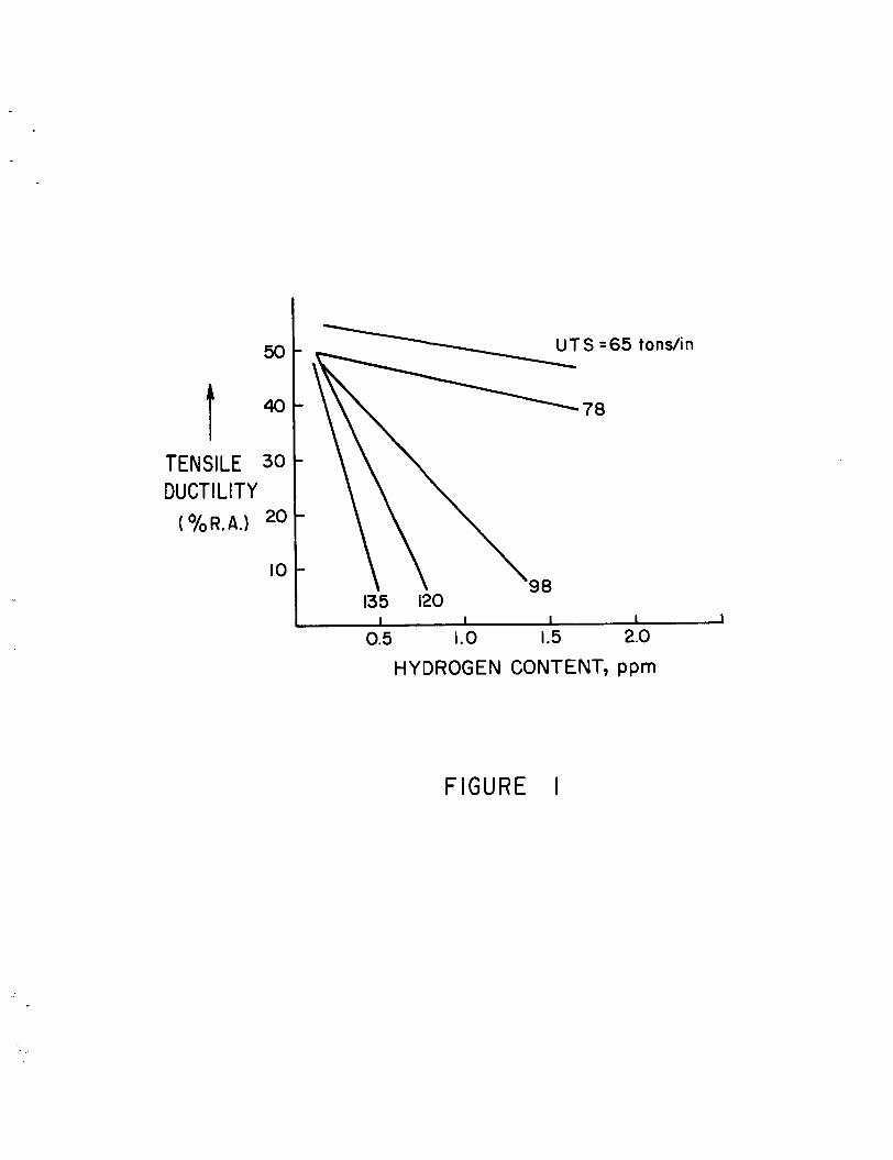
50
TENSILE 30 DUCTILITY
20 ( % R. A.)
10
65 tons/i n
78
- - 135 120
0.5 1.0 I .5 2.0
HYDROGEN CONTENT, ppm
FIGURE I

t APPLIED STRESS
TIME TO FRACTURE r
T I M E - FIGURE 2
= LOWER CRITICAL S T R E S S

F GURE 3

FIGURE 4

t C
NO GO 4
t C
SLOW GO I 1 - L
7 t GO (UNSTABLE)
cF
CO
t C
cF
CO
- u
I I
CONSTANT STRESS
I I * TIME t* I tF
- -
FIGURE 5

CHARPY V IMPACT ENERGY
I
TEMPERATURE
FIGURE 6
STRENGTH STEEL
STEEL

I >- c
W I- W J I- + cc - m
t 0
0
e W I-
a
FIGURE 7

0.07
0.06
0.05
0.04
0.03
0.02
0.01
R H """7
0 20 25 30 35 40
Stress field parameter K- (103x Ib/in2xfi)
FIGURE 8

cH
INITIAL CONCENTRATION
-DISTANCE - FIGURE 9


IC ROC RACK NUCLEUS
FIGURE II

L 0
+t,t+ ti
I I l l 1 I I I I I I l l
QD I 0
IO0
FRACTURE
FIGURE 12

.- v) CL 0 0 0 - mi
a
n
v) W
t cn W
CL CL
- a
50
300
250
200
I50
IO0
+ I I I I 1
N o r m a I Notch Strength = 300.000 osi N o r m a l Notch Strength = 300,000 psi
--- Bake 24 hrs.
18 hrs. \ \
12 hrs. \
3 hrs.
0.5 hr.
7 hrs.
FIGURE 13

N
N
I I I I
HYDROGEN
FIGURE 14

r C R A C K
0
AC +/vo'Ds
0 (b)
FIGURE 15
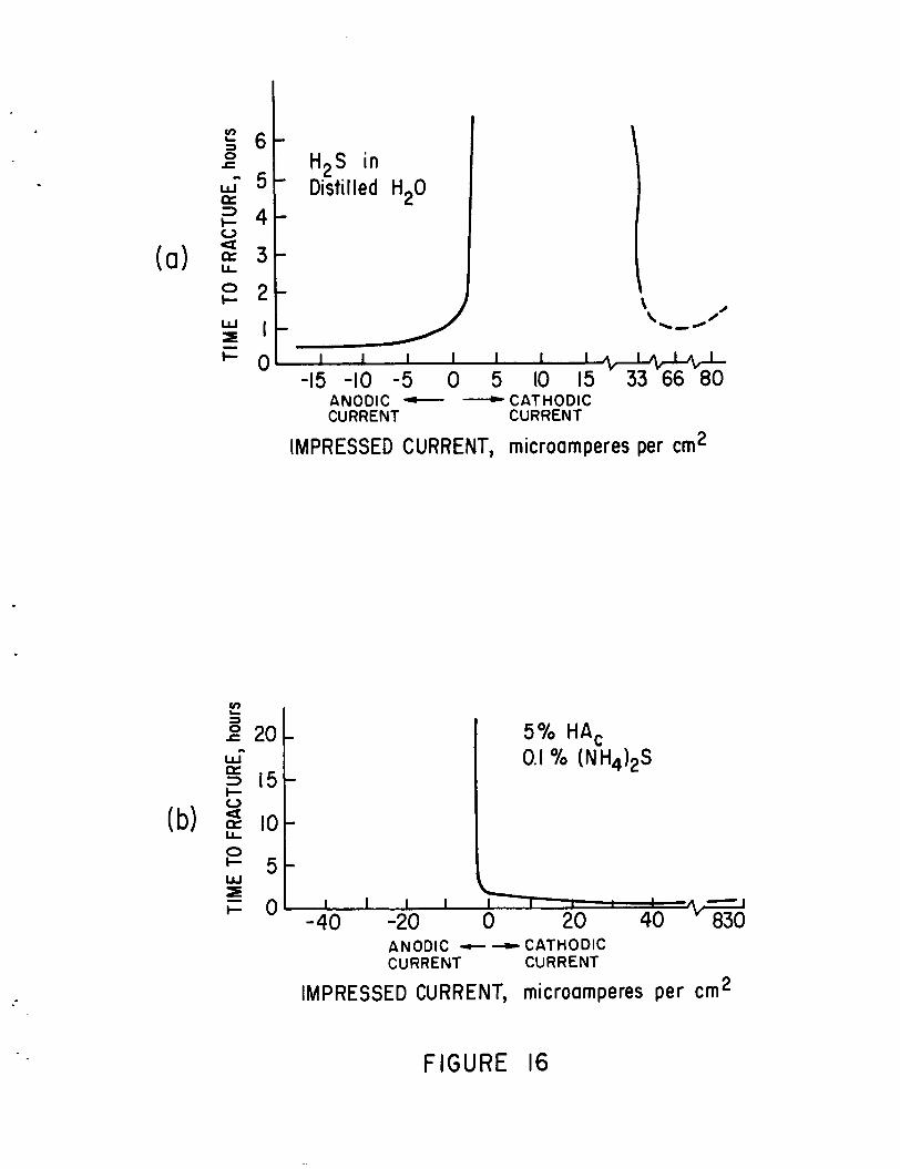
2 6 3
a
0 c W - 5 2 4
c r" 20- W- a 3 15-
3
I-
(b) % LL I O - 0
W I + 5 -
i = o
H2S in * Distilled H20
5 % HAc 0.1 To (NH,)*S
I 1 I I I I I I A -
-15 -10 -5 0 5 10 15 33 -66 -80 ANODIC - - CATHODIC CURRENT CURRENT
IMPRESSED CURRENT, microamperes per cm2
ANODIC - - CATHODIC CURRENT CURRENT
IMPRESSED CURRENT, microamperes per cm2
FIGURE 16

.
0
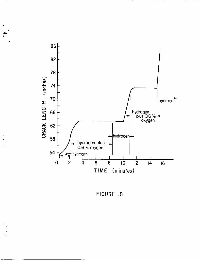
. - I
mB *
- hydrogen
86
02
78
74
70
66
62
58
54
c hydrogen
PIUS 0.6% oxygen
I- ]k hydrogen plus 0.6% oxygen
h y d myen I I I I I I I
0 2 4 6 8 IO 12 14 16 T I M E ( minutes)
FIGURE 18