Embed Size (px)
Citation preview

Caitlin Ferrell
Senior Thesis, 2006
Erie Convention Center and Sheraton Hotel
Erie, Pennsylvania
The Pennsylvania State University ·Architectural Engineering

Erie Convention Center and Sheraton Hotel
Erie, Pennsylvania
Caitlin Ferrell Structural Option Penn State University http://www.arche.psu.edu/thesis/eportfolio/current/portfolios/cmf212/
The Project Team: Owner: Erie Convention Center Authority
Architects: DRS Architects
General Contractor: Barton Malow
MEP Engineers: Karpinski Engineering
Structural Engineers: Atlantic Engineering Services
Architecture: • Keeps views of Presque Isle Bay • Based on Sheraton’s signature "low−rise Soho" prototype, adapted to a high−rise expression • Exterior materials: pre−cast concrete base, copper cladding, green tinted glazing, panelized EIFS wall system, and red brick • Pedestrian bridge connection to Bayfront Convention Center from 5th floor
Mechanical: • CAV air system • FCU’s for additional loads in multi−use areas • Radiant floor entry • Hotel rooms have individual air conditioning units
Electrical: • 277/480 3 phase, 4 wire, utility distribution voltage • 120/208 3 phase, 4 wire, building distribution voltage • 500 kW diesel generator for emergency backup
Lighting: • 8" diameter triple tube compact fluorescent down−lights • Wall sconces • Cold cathode recessed horizontal mounted cove fixtures
Structural: • Caissons, piers, and grade beam foundation • Steel structure with 8" pre−cast concrete plank
paneled floors • Cross−braced lateral system
Building Statistics: Size: 132,000 sq. ft. 11 Stories 200 Guest rooms Construction Dates: Spring 2006−2007 Project Delivery Method: Design−Bid−Build Cost: $62 million (including Bayfront Convention Center)
ii

Caitlin Ferrell Erie Convention Center and Sheraton Hotel
iii
Table of Contents Cover Page ........................................................................................................................................ i
Abstract ............................................................................................................................................ ii
Table of Contents............................................................................................................................iii
Executive Summary ......................................................................................................................... 1
Background...................................................................................................................................... 2
Site and Architecture........................................................................................................................ 2
Existing Structural System............................................................................................................... 4
Depth Work...................................................................................................................................... 6
Introduction......................................................................................................................... 7
Gravity Design Loads and Floor Design ............................................................... 7
Lateral Design Loads ............................................................................................. 9
Load Combinations.............................................................................................. 12
Truss Theory and Design..................................................................................... 12
Truss Member Sizes............................................................................................. 16
Building Drift Due to Lateral Load ..................................................................... 18
Precast Plank vs. Steel Joists ............................................................................... 19
Additional Factors................................................................................................ 20
Structural Conclusions......................................................................................... 21
Breadth Work................................................................................................................................. 23
Mechanical
Introduction.......................................................................................................... 24
Geothermal Heat Pump........................................................................................ 24
Acoustics
Introduction.......................................................................................................... 27
Transmission Loss and Sound Absorption .......................................................... 27
Summary and Conclusions ............................................................................................................ 31
References...................................................................................................................................... 32
Acknowledgements........................................................................................................................ 33
Appendices........................................................................................................................................I
Appendix 1: Precast Plank Design.................................................................................................. II
Appendix 2: Steel Joist Floor System Design................................................................................ III
Appendix 3: Staggered Truss Member Sizes ................................................................................. IV

Caitlin Ferrell Erie Convention Center and Sheraton Hotel
1
Executive Summary The Erie Convention Center and Sheraton Hotel is an eleven story, 132,000 square foot hotel and convention center, which is part of the Bayfront Convention Center complex, located in Erie, Pennsylvania. The existing structure, a steel frame with a precast concrete plank floor system, proves to be efficient in its design and constructability; however a staggered truss system provides an alternative to this structural system and was designed and analyzed in depth in this report. A staggered truss system creates open, two bay spaces by eliminating interior columns with the use of floor to floor height trusses on alternating floors. In addition to designing the staggered truss system, the affects that various floor systems can have on the member sizes of the trusses was also investigated. Two floor systems, a hollow core precast plank floor system and a steel joist with deck and concrete slab floor system, were designed. Using these floor systems, two ETABS models were created in order to size the structural members for the staggered truss system based on the differences in the floor systems. Final conclusions were based on cost, schedule, and impacts on architecture. My breadth topics in this report investigate an alternative to the current heating and cooling system used, as well as a study of the current acoustics and sound level in between two guestrooms. A lake source open-loop geothermal heat pump was considered in replacement of the conventional air-to-air used. This air-to-water system is much more efficient and will save on electricity needed to heat and cool the building, therefore decreasing the amount of money spent. The money saved per year by using this geothermal heat pump was determined and compared with the first cost to calculate the payback period. Sound transfer through hotel rooms is a concern, however appropriate noise reduction values were not given. In order to ensure the guests’ comfort, I evaluated two typical adjacent guest rooms. The transmission loss through the shared wall as well as the noise reduction was found. Finally, based on the sound pressure of humans talking in one room, the sound pressure in the adjacent room was calculated and compared to ambient sound conditions. From these studies, I concluded the following:
• The precast plank system is more effective than the steel joist system based on a small floor sandwich, constructability, cost, and affects on the exterior architecture.
• A staggered truss system is cheaper and will have a shorter construction time than the proposed steel frame structure.
• The payback period of approximately three months for the first cost installation of the geothermal heat pumps makes this a much better alternative to the existing heating and cooling system.
• The sound transfer in between two typical adjacent guest rooms is at an acceptable amount.
Caitlin Ferrell Erie Convention Center and Sheraton Hotel
2
Background In April 2002, the largest development project in Erie, Pennsylvania’s history was underway with the presentation of a $32-million check to the Erie County Convention Center Authority for the construction of the Bayfront Convention Center and surrounding complex.
This complex includes a supplementary part of the Erie Convention Center, along with a Sheraton Hotel. Additional state funding was granted in August 2004, bringing the total to $44-million, to be added to funds donated by local businesses. The location of the new complex is the revitalized bayfront of Erie along the Preque Isle Bay. The owner, the Erie County Convention Center Authority, along with the development manager, Acquest Realty Advisors, and the hotel franchisor, Starwood Hotels and Resorts Worldwide, made up the head of the primary
project team. The design-bid-build project delivery rewarded the general contractor position to Barton Malow Co. DRS Architects and Atlantic Engineering Services, both located in Pittsburgh, PA were responsible for the architecture and structural engineering, respectively. Karpinski Engineering was the MEP Engineers for the project, while the civil engineering was completed by Urban Engineers of Erie. The ground breaking in August 2005 began the construction of the complex. Construction is expected to be completed in the summer of 2007. Site and Architecture
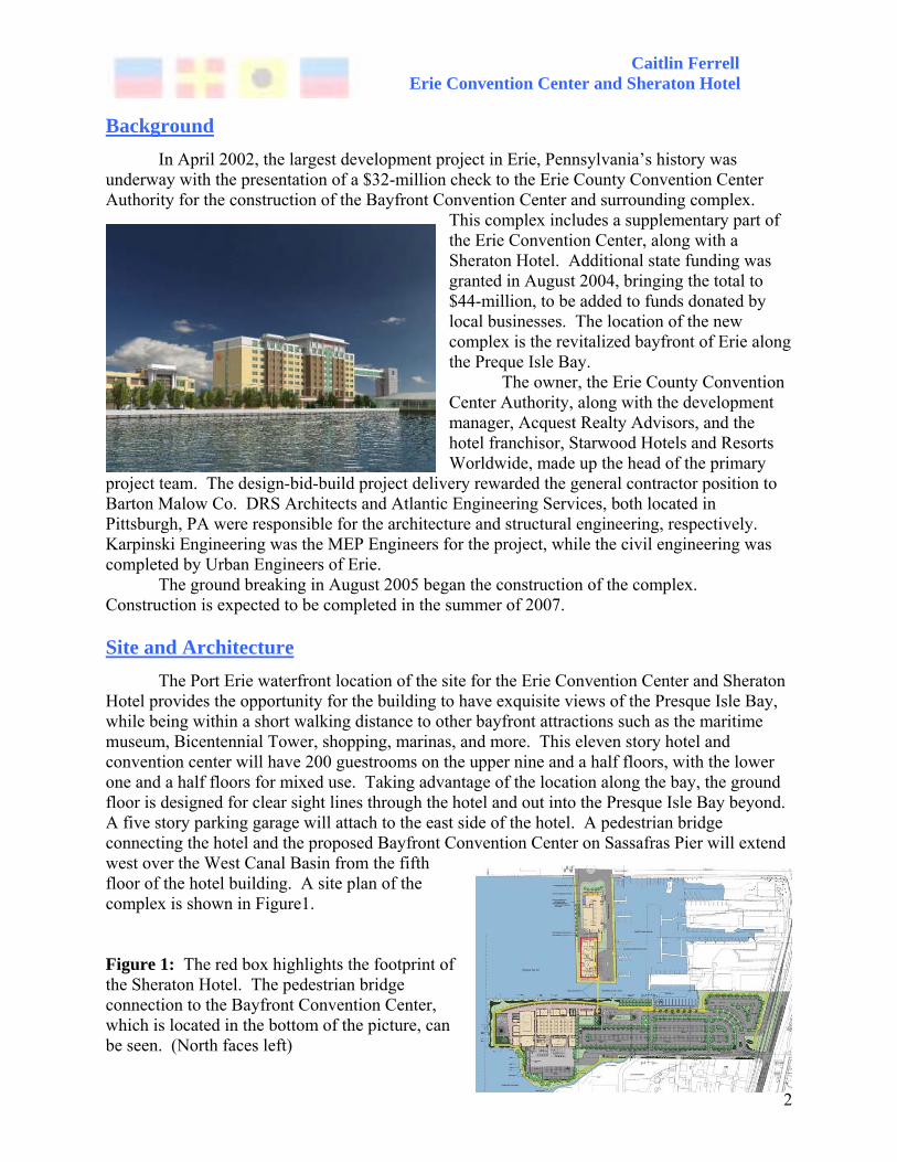
The Port Erie waterfront location of the site for the Erie Convention Center and Sheraton Hotel provides the opportunity for the building to have exquisite views of the Presque Isle Bay, while being within a short walking distance to other bayfront attractions such as the maritime museum, Bicentennial Tower, shopping, marinas, and more. This eleven story hotel and convention center will have 200 guestrooms on the upper nine and a half floors, with the lower one and a half floors for mixed use. Taking advantage of the location along the bay, the ground floor is designed for clear sight lines through the hotel and out into the Presque Isle Bay beyond. A five story parking garage will attach to the east side of the hotel. A pedestrian bridge connecting the hotel and the proposed Bayfront Convention Center on Sassafras Pier will extend west over the West Canal Basin from the fifth floor of the hotel building. A site plan of the complex is shown in Figure1. Figure 1: The red box highlights the footprint of the Sheraton Hotel. The pedestrian bridge connection to the Bayfront Convention Center, which is located in the bottom of the picture, can be seen. (North faces left)

Caitlin Ferrell Erie Convention Center and Sheraton Hotel
3
The architecture is based on Sheraton’s signature low-rise ‘Soho’ prototype adapted to a high-rise expression. The hotel and convention center has a buff-colored precast concrete base, rising to mid-first floor, and is detailed with copper cladding. The tinted green glass windows are accented with silver aluminum mullions and green louvers or metal panels. The exterior wall material is a combination of a panelized EIFS wall system in four different light shades in contrast with red brick, attached to the light gage stud wall structural system. This contrast is seen in the brick “columns” that are offset by the green tinted windows and light cream stucco background. The two story front entrance is approximately 75ft. x 45 ft. and allows for safe drop off and pick up of guests and visitors, protecting them from any harsh weather that may occur.
The site, West Dobbins Landing, was developed gradually by placing timber cribbing and filling with fill materials readily available at the time. The bulkheads on the north, west and south sides were constructed about 15 years ago, and are made of soldier pile walls with concrete wall panels. The site used to house different marinas and boat works. These have been razed; however, some of the foundations may still remain. Because of the historical use as a marine facility, there is also a chance of underground storage tanks on site.
The following two pictures show views of the Bayfront Convention Center. In both pictures, portions of the Sheraton hotel can be seen.

Caitlin Ferrell Erie Convention Center and Sheraton Hotel
4
Existing Structural System The center tower of the Erie Convention Center and Sheraton Hotel reaches an overall height, including mechanical penthouses and parapets, of 155 feet. The footprint is 175. 5 feet by 57 feet and is comprised of 3 bays in the North/South direction, and 7 bays in the East/West direction. Figure 2 shows the basic framing layout and member sizes of the tower.
The lateral resisting system of the tower is located on the four perimeter walls. Both diagonal cross-braces and eccentric knee braces are located in the North/South direction, while moment connections resist lateral loads in the East/West direction. The eccentrically braced frames allow for vertical ribbon windows, while providing the structural stability needed to resist the winds coming off of Lake Erie (Figure 3).
Figure 2: The tower portion of the Erie Convention Center and Sheraton Hotel has a typical framing plan as shown here. The three bays in the North/South direction are sized 19’, 15’, and 23’. In the East/West direction, the two exterior bays are 25’-3”, with five 25’ interior bays.

Caitlin Ferrell Erie Convention Center and Sheraton Hotel
5
Figure 3: The West Elevation of the lateral bracing is shown here with the combination of diagonal cross braces, as well as eccentric knee braces. The first three floors on the West Elevation have all cross braces because of the attached parking garage. The East Elevation has eccentric knee braces to the ground which allows for the ribbon window to be carried down through the first three floors. The structural system is comprised of steel framing members that support a floor system of 8-inch hollow core precast concrete planks that span in the East/West direction. The design used for the Erie Convention Center and Sheraton Hotel specifies that no topping is needed except for a ¼” polymer modified cement product for leveling in select places. Grout placed in between the sections of the plank will allow the floor system to act as a diaphragm for the lateral analysis. The building is supported by a foundation system composed of caissons, monolithically cast concrete grade beams and piers, and an 8” structural slab on grade. The caissons have a minimum required diameter of 24”, are drilled approximately 20 feet deep, and are made of 3000 psf concrete. By drilling three feet into the bedrock, the net allowable end bearing pressure is 40 ksf. In addition, shaft resistance can be added to the caisson capacity using 3.0 ksf allowable side friction applied to the socket surface area in the bedrock.

Caitlin Ferrell Erie Convention Center and Sheraton Hotel
6
Depth Work
Staggered Truss Design
Compares Precast Concrete Plank to a Steel Joist Floor System
Caitlin Ferrell Erie Convention Center and Sheraton Hotel
7
Introduction The Erie Convention Center and Sheraton Hotel is currently being constructed of a steel frame with a hollow core precast plank flooring system. This steel system is comprised of columns, beams, and girders, with lateral forces resisted by moment connections in the East/West direction, and braced frames in the North/South direction. This system is effective in resisting lateral loads, while fitting the typical grid of a hotel building.
When examining possible alternatives to a structural system, a staggered truss system, often used in hotels and apartment buildings, appears to be the most appropriate alternative. Through the use of this system, low floor to floor heights can be obtained when used in conjunction with hollow core precast plank. In addition, column-free areas as large as 60-70 feet can be obtained because of the staggered floor to floor height truss configuration. These trusses will resist the lateral loads in the N/S direction, while moment connections will resist lateral loads in the E/W direction.
The following sections will include the design criteria used for the gravity and lateral loading of the staggered truss system. Two alternative floor systems used in conjunction with the staggered truss system will also be analyzed: a hollow core precast plank floor similar to the one used in the existing building, and a floor system comprised of open web steel joists with metal deck and a concrete slab. The theory and design of the staggered truss system will also be discussed, along with the results of the design and final conclusions. Gravity Design Loads and Floor Design
The following gravity loads were used in order to design the two floor systems being analyzed in conjunction with the staggered truss framing system: hollow core precast plank, and steel joist with metal deck and concrete slab.
Live Loads: (IBC 2003 Table 1607.1, unless noted otherwise)
• Public Rooms and Corridors = 100 psf • Private Rooms and Corridors = 40 psf • Stairs = 100 psf • Mechanical Spaces (Assumed) = 150 psf • Ground Snow Load pg (Fig. 1608.2) = 30 psf
Ce=0.8 (fully exposed, exposure category D) Ct=1.0 I=1.0 (Building category II) pf=0.7 Ce Ct I pg =16.8 psf
Caitlin Ferrell Erie Convention Center and Sheraton Hotel
8
Precast Hollow Core Floor- See Appendix 1 for hollow-core plank design charts of 8” precast hollow core plank with 2” topping. Dead Loads: (Assumed in conjunction with AISC Staggered Truss Framing Systems
Design Guide) • Structural Steel = 5 psf • 8” precast hollow core plank with 2” topping = 81 psf
(PCI Design Handbook) • Metal Stud Walls with 5/8” gypsum wall board = 10 psf • MEP = 10 psf • Carpet = 1 psf • Ceiling Finishing = 1 psf __________________________________________________ Total Dead Loads = 108 psf
Steel Joist Floor with Metal Deck and Concrete Slab-
Joists are 3’ o.c. (57’ wide with joist at 3’o.c 19 spaces, 20 joists) 22K7 (floor 2) 18K4 (floors 3-11) See Appendix 2 for joist design.
Dead Loads: (Assumed in conjunction with AISC Staggered Truss Framing Systems Design Guide)
• Structural Steel = 5 psf • Metal Stud Walls with 5/8” gypsum wall board = 10 psf • MEP = 10 psf • Carpet = 1 psf • Ceiling Finishing = 1 psf • Concrete Slab and Deck = 39 psf • Joist (conservative estimate) = 4 psf __________________________________________________ Total Dead Loads = 70 psf

Caitlin Ferrell Erie Convention Center and Sheraton Hotel
9
Lateral Design Loads The following design conditions and lateral loads, both wind and seismic were calculated using ASCE 7-02. Similar calculations were completed as part of Technical Assignment #3. Full final calculations are available upon request. Wind Loads: Basic Wind Speed 90 mph Exposure Category D Enclosure Classification Enclosed Building Category II Importance Factor 1.00 Seismic Loads: Seismic Use Group I Occupancy Importance Factor 1.0 Site Classification E 0.2s Acceleration (Figure9.4.1.1a) 0.13 1s Acceleration (Figure 9.4.1.1b) 0.059 Site Class Factor, Fa (Table 9.4.1.2.4a) 2.5 Site Class Factor, Fv (Table 9.4.1.2.4b) 3.5 Response Modification Factor (E/W) 3.5 (for ordinary steel moment frames) Response Modification Factor (N/S) 3.0 (conservative for staggered truss) A response modification factor of 3.0 was chosen for seismic design in the N/S direction, which is the direction of the staggered trusses. An R of 3.0 is the most conservative value, which does not require special detailing for seismic forces. Even though an R factor of 7 or 8 could be applied if the staggered truss system is considered to act as an eccentrically braced frame, using an R of 3, is the most conservative.

Caitlin Ferrell Erie Convention Center and Sheraton Hotel
10
Shown below are two tables containing the story forces and story shears for the staggered truss system with the hollow core precast plank floor system. It can be seen that in the N/S direction, wind forces control, while in the E/W direction, the seismic forces control. This is expected that the wind will control in the N/S direction, because of the large surface area that the wind is in contact with.
Plank Design Story Forces (kips) N/S E/W Floor Wind Seismic Wind Seismic roof 28.13 27.15 7.70 20.4911 55.93 64.66 15.18 48.2710 55.59 56.17 15.18 41.449 55.15 47.99 15.47 34.948 54.70 40.15 14.88 28.797 53.81 32.67 14.51 23.036 52.69 25.61 14.13 17.685 52.02 19.00 13.83 12.804 59.10 12.94 15.70 8.443 76.93 7.53 20.30 4.692 86.17 2.98 22.55 1.721 39.87 0 10.36 0
Plank Design Story Shear (kips) N/S E/W Floor Wind Seismic Φh (%) Wind Seismic Φh (%) roof 0.00 0.00 0.0 0.00 0.00 0.0 11 28.13 27.15 4.3 7.70 20.49 8.5 10 84.06 91.82 14.6 22.88 68.76 28.4 9 139.65 147.99 23.5 38.05 110.20 45.5 8 194.80 195.97 31.1 53.52 145.13 59.9 7 249.50 236.12 37.5 68.40 173.93 71.8 6 303.30 268.79 42.7 82.91 196.96 81.3 5 355.99 294.40 46.7 97.04 214.64 88.6 4 408.01 313.41 64.7 110.87 227.44 93.9 3 467.11 326.34 74.1 126.57 235.87 97.4 2 544.04 333.87 86.3 146.87 240.56 99.3 1 630.21 336.85 100.0 169.42 242.28 100.0

Caitlin Ferrell Erie Convention Center and Sheraton Hotel
11
Shown below are two tables containing the story forces and story shears for the staggered truss system with steel joist and slab floor system. It can be seen that in the N/S direction, wind forces control, while in the E/W direction, the seismic forces control. This is expected that the wind will control in the N/S direction, because that is when it is hitting the wide side of the building. Notice that the seismic forces for the joist floor system are less than the design forces for the plank floor system because of the decrease in building weight.
Joist Design Story Forces (kips) N/S E/W Floor Wind Seismic Wind Seismic roof 28.13 26.57 7.70 20.0111 55.93 42.25 15.18 31.4810 55.59 36.70 15.18 27.029 55.15 31.36 15.47 22.788 54.70 26.23 14.88 18.787 53.81 21.35 14.51 15.026 52.69 16.73 14.13 11.535 52.02 12.42 13.83 8.354 59.10 8.45 15.70 5.503 76.93 4.92 20.30 3.062 86.17 1.95 22.55 1.121 39.87 0.00 10.36 0.00
Joist Design Story Shear (kips) N/S E/W Floor Wind Seismic Φh (%) Wind Seismic Φh (%) roof 0.00 0.00 0.0 0.00 0.00 0.0 11 28.13 26.57 4.2 7.70 20.01 12.2 10 84.06 68.82 10.9 22.88 51.49 31.3 9 139.65 105.52 22.2 38.05 78.52 47.7 8 194.80 136.88 30.9 53.52 101.30 61.5 7 249.50 163.11 39.6 68.40 120.08 72.9 6 303.30 184.46 48.1 82.91 135.10 82.0 5 355.99 201.19 56.5 97.04 146.63 89.1 4 408.01 213.61 64.7 110.87 154.98 94.1 3 467.11 222.06 74.1 126.57 160.48 97.5 2 544.04 226.98 86.3 146.87 163.54 99.3 1 630.21 228.93 100.0 169.42 164.66 100.0
Caitlin Ferrell Erie Convention Center and Sheraton Hotel
12
Load Combinations The following seven LRFD load combinations were considered for the design of the structure:
• 1.4 D • 1.2 D + 1.6 L + 0.5 R • 1.2 D + 1.6 R + L • 1.2 D + 1.6 W + L + 0.5 R • 1.2 D + 1.0 E + L + 0.2 S • 0.9 D + 1.6 W • 0.9 D + 1.0 E
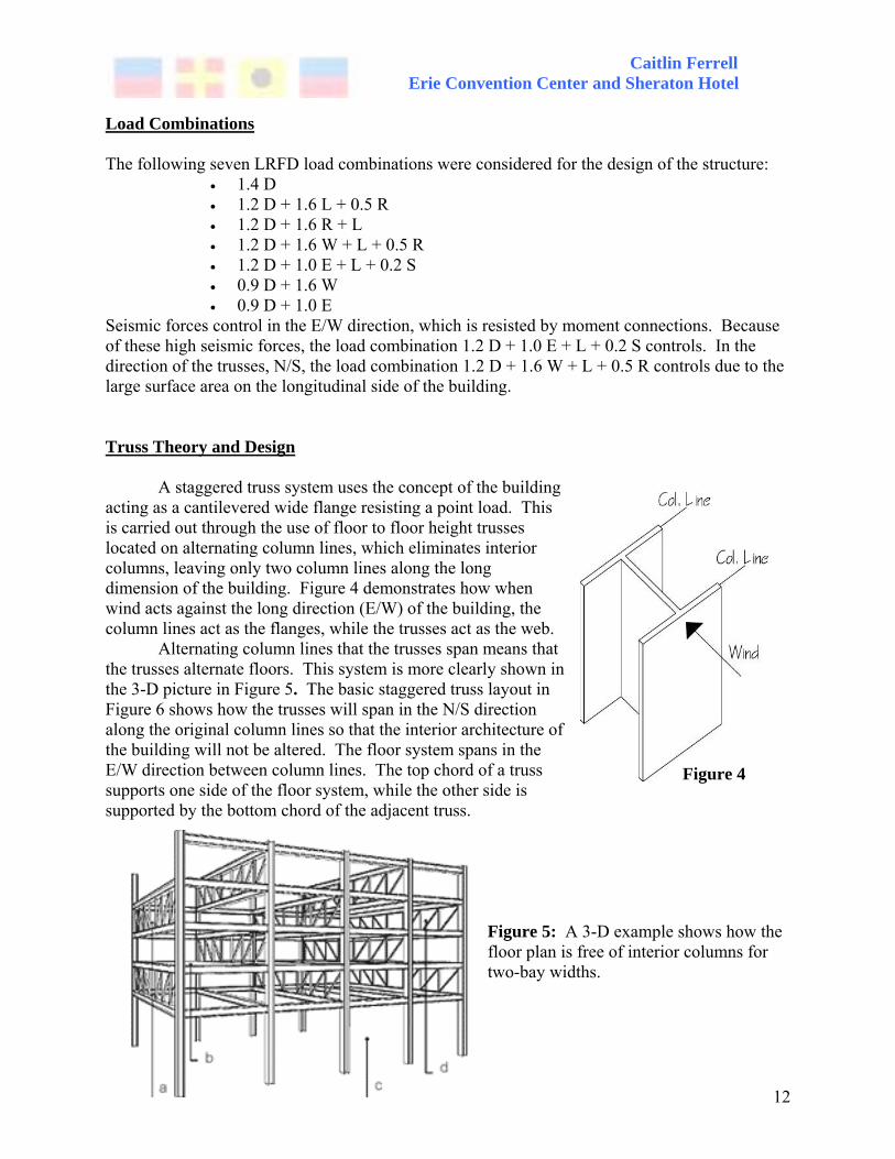
Seismic forces control in the E/W direction, which is resisted by moment connections. Because of these high seismic forces, the load combination 1.2 D + 1.0 E + L + 0.2 S controls. In the direction of the trusses, N/S, the load combination 1.2 D + 1.6 W + L + 0.5 R controls due to the large surface area on the longitudinal side of the building. Truss Theory and Design A staggered truss system uses the concept of the building acting as a cantilevered wide flange resisting a point load. This is carried out through the use of floor to floor height trusses located on alternating column lines, which eliminates interior columns, leaving only two column lines along the long dimension of the building. Figure 4 demonstrates how when wind acts against the long direction (E/W) of the building, the column lines act as the flanges, while the trusses act as the web.
Alternating column lines that the trusses span means that the trusses alternate floors. This system is more clearly shown in the 3-D picture in Figure 5. The basic staggered truss layout in Figure 6 shows how the trusses will span in the N/S direction along the original column lines so that the interior architecture of the building will not be altered. The floor system spans in the E/W direction between column lines. The top chord of a truss supports one side of the floor system, while the other side is supported by the bottom chord of the adjacent truss.
Figure 5: A 3-D example shows how the floor plan is free of interior columns for two-bay widths.
Figure 4

Caitlin Ferrell Erie Convention Center and Sheraton Hotel
13
Figure 6: It can be seen in the floor plan above, that only the columns along column lines 1 and 2 remain. The trusses on the even floors are represented by A1, A2, A3, and A4, while B1, B2, B3, and B4 represent trusses on odd floors.
The trusses themselves are Pratt trusses typically composed of W-shape chords with hollow structural section diagonal members. There must be an open Vierendeel panel in the center to allow for a corridor. Gravity loads from the floor system are applied to the top and bottom chords. The trusses will provide resistance to lateral loads in the N/S direction, while moment connections will resist lateral loads in the E/W direction. The truss frames are considered to have pin joints, assuming that no moment is transferred through the joints or between members. Figure 7 shows a typical truss. Welded gusset plates provide the connection between the web members and truss chords.
Figure 7: The floor-to-floor height trusses that span the N/S direction, resist both gravity loads and lateral loads acting in the N/S direction.

Caitlin Ferrell Erie Convention Center and Sheraton Hotel
14
To begin the design process of the staggered truss system, the distribution of lateral forces through rigid diaphragm action was initially investigated. The assumption is made that each truss has approximately the same shear rigidity. Lateral loads are transferred from truss to truss through the diaphragm at each floor, carrying the lateral loads from the top of the building, to the ground. To resist the lateral load, it is assumed that each of the four trusses on each floor take an equal amount of the load. This load is then transferred through the diagonal members of the trusses to the diaphragm, which then transfers the shear load to the trusses on the next floor. Because of the staggered arrangement, each of the interior trusses is responsible for resisting two bays of lateral load. Figure 8 demonstrates this distribution of horizontal forces.
Figure 8: Per column spacing, each truss takes two bays of the lateral force, H.
Both the precast plank floor system and the steel joist floor system act as a rigid
diaphragm, causing the same load distribution. Since the wind load case controls in the N/S direction, the base shear is the same for both floor systems, thus there is the same amount of shear on each truss.
The torsional rigidity of the structure can be determined by taking the distance from the trusses to the center of rigidity. These values for the trusses on the even floors can be seen in the chart below (Assume that the equation is multiplied by a constant stiffness factor, R, for each truss).
Torsional Rigidity Truss xi xi
2 A1 -75.25 5662.563 A2 -24.92 621.0064 A3 25.08 629.0064 A4 75.08 5637.006
Σ= 12549.58 ft2

Caitlin Ferrell Erie Convention Center and Sheraton Hotel
15
The torsional shear for each truss can then be calculated using the equation VTORS = Rx/ΣRx2 * MT, where MT= VBASE WIND * (distance from center of rigidity to center line). The base torsion is found by multiplying the base shear by the eccentricity due to an accidental torsion of 5%. Note that the torsional shear components have opposite signs on each side of the center line which says that they are in opposite directions, opposing the moment created by the direct force offset from the center of the building.
Torsional Shear
Truss Rx ΣRx2 Rx/ΣRx2 MT VTORS A1 -75.25 12549.58 -0.006 7877.59 -47.24 A2 -24.92 12549.58 -0.00199 7877.59 -15.64 A3 25.08 12549.58 0.001998 7877.59 15.74 A4 75.08 12549.58 0.005983 7877.59 47.13
Base Torsion, T Vbase ee eo Te To 630 21.36 -3.8 13461.23 -2394.79
Finally, the design shear for each of the trusses can be calculated by adding the shear on
each truss due to a direct load (VS=VBASE/4) to the torsional shear. The values for the trusses on the second floor are shown in the following table. Figure 9 demonstrates the directions of the shear forces in the trusses due to the direct forces and the torsional forces. The direct forces all run in the same direction, while the torsional forces create a moment by acting in opposite directions on each side of the center of rigidity. This accounts for the larger shear values in trusses A3 and A4.
Shear Force in Each Truss due to Lateral Loads (Bottom Floor)
Te= 13461.23 To=-2394.79 Design Shear V (kips) Truss xi Vs
VTORS Vi VTORS Vi Vi
Φecc
A1 -75.25 210.07 -47.54 162.53 -47.54 162.53 162.53 1.00A2 -24.92 210.07 -15.74 194.33 -15.74 194.33 194.33 1.20A3 25.08 210.07 15.84 225.91 15.84 225.91 225.91 1.39A4 75.08 210.07 47.43 257.50 47.43 257.50 257.50 1.58

Caitlin Ferrell Erie Convention Center and Sheraton Hotel
16
Figure 9: The lateral load causes direct shear forces, Fd, in each of the trusses. Because the load is offset from the center of rigidity, a moment is also induced, creating the torsional shear components, Ft. Truss Member Sizes For the design of the actual members of the building, a 3-D computer model was built using ETABS. The basic geometry for the building and truss size and location was entered along with the application of seismic and wind forces including load combinations for design. The structural system of the staggered truss system is comprised of three parts: the spandrel beams, which run in between and perpendicular to the trusses on the exterior of the building in the E/W direction, the columns, which are only located on the exterior edges of the building in the E/W direction, and the trusses. Each truss is erected as a single piece and is connected to the columns.
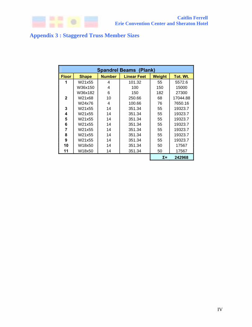
Typical spandrel beams for the precast plank floor system range from W18×50 to W36×182, with the most common beam size as a W21×55. The W36×182 beams are located on the bottom floor. While these beams seem like they are sized large, there is an 18’ story height above and below these beams. These beams are most likely sized large for stiffness to resist lateral forces. The most common size for the spandrel beams for the joist system is a W18×50.
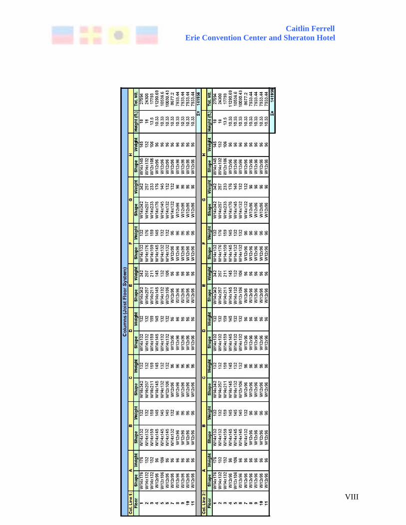
Columns are designed for combined axial and bending forces due to truss axial deformation and vertical deflection due to gravity loads. Columns for both floor systems range from W12×96 on the top floors, to large W14’s on the bottom floor. These columns are large partly due to the 18’ height of the bottom two floors. In addition, where hangers are present on the second floor, the first diagonal to column connection will carry three floors of load. This column layout can be seen more clearly in the 3-D image in Figure 10.

Caitlin Ferrell Erie Convention Center and Sheraton Hotel
17
Figure 10: This is a 3-D model of the staggered truss system designed for the Erie Convention Center and Sheraton Hotel created in ETABS. Here, a better view of the open first floor can be seen.
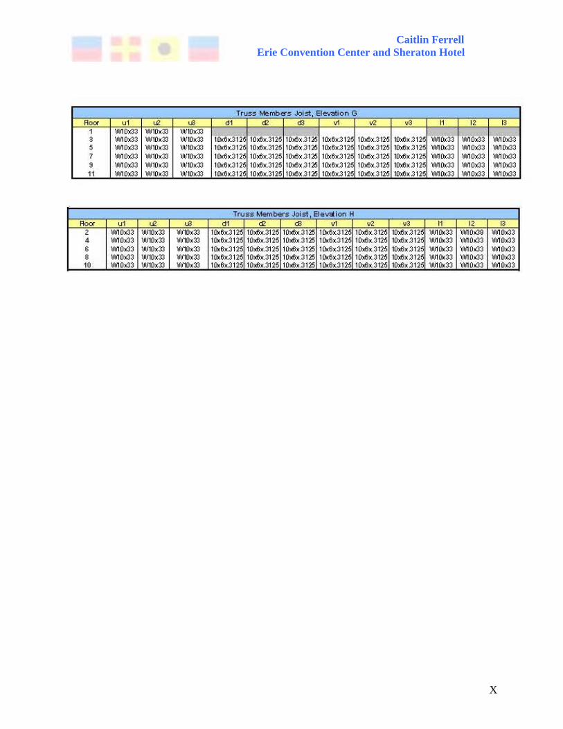
The N/S elevations, once the trusses are fully erected, are shown in Figure 11. Type A
and Type B configurations are located on adjacent column lines and are referenced in the floor plan in Figure 6. The chords, labeled U2, U2, U3, L1, L2, and L3 in Figure 11 are W10 shapes, the most common one being a W10×33. These chords are designed using the member forces due to gravity and wind loads, where the maximum moment is located in the Vierendeel panel. The diagonal (d1, d2, d3) and vertical (v1, v2, v3) members are hollow structural sections, the most common size being HSS 10×6×5/16. The diagonal and vertical members on the left and right side of the truss are the same due to symmetry. These vertical and diagonal members are designed by solving the member forces individually due to gravity loads applied at panel points, and lateral loads applied at story heights, and combining them to size the members. The first floor for the Type A elevation needs additional supports or hangers, which are HSS 10×6×5/16, located at each of the panel points of the truss on the second floor. For the Type B layout, HSS 10×6×5/16 posts are needed on the eleventh story. In addition, diagonal W-shape braces are needed on the first floor of the Type B layout for lateral support.

Caitlin Ferrell Erie Convention Center and Sheraton Hotel
18
Figure 11: These are two section elevations of the layout of the staggered truss system for the odd floors (Type A), and the even floors (Type B). Full results and member sizes can be found in Appendix 3. Building Drift due to Lateral Loads
Under the controlling load combination 1.2 D + 1.6 W + L + 0.5 R in the N/S direction, the maximum drifts are as follows:
• Precast Plank System– 2.7” • Steel Joist System– 1.68”
The allowable drift for serviceability due to wind is Δ= H/400 = 132’(12”/1’)/400 = 3.96”. The drift in the N/S direction for both floor systems, meets this criterion.
For the controlling load combination 1.2 D + 1.0 E + L + 0.2 S in the E/W direction, the
allowable drift per floor must not exceed two percent of the story height. The following tables conclude that the drift of the building in the E/W direction under the controlling seismic load combination is acceptable.

Caitlin Ferrell Erie Convention Center and Sheraton Hotel
19
Seismic Drift Check (Plank) Story Height (ft) Displacement Drift Drift/(Ht*12)
11 10.33 3.884507 0.051647 0.0004166 10 10.33 3.83286 0.190002 0.0015328 9 10.33 3.642858 0.155166 0.0012517 8 10.33 3.487692 0.257941 0.0020808 7 10.33 3.229751 0.242519 0.0019564 6 10.33 2.987232 0.328583 0.0026507 5 10.33 2.658649 0.288337 0.002326 4 10.33 2.370312 0.367117 0.0029616 3 13.5 2.003195 0.45148 0.0027869 2 18 1.551715 0.642712 0.0029755 1 18 0.909003 0.909003 0.0042083
Seismic Drift Check (Joist)
Story Height (ft) Displacement Drift Drift/(Ht*12) 11 10.33 4.490514 0.02905 0.0002343 10 10.33 4.461464 0.145588 0.0011745 9 10.33 4.315876 0.130601 0.0010536 8 10.33 4.185275 0.22455 0.0018115 7 10.33 3.960725 0.194364 0.001568 6 10.33 3.766361 0.2728 0.0022007 5 10.33 3.493561 0.234066 0.0018882 4 10.33 3.259495 0.330678 0.0026676 3 13.5 2.928817 0.475886 0.0029376 2 18 2.452931 0.974549 0.0045118 1 18 1.478382 1.478382 0.0068444
Precast Plank vs. Steel Joists . Between the two floor systems considered, the precast plank floor system appears to be the better choice. While some of the members in the structural system with the steel joist floor system are smaller, on average the members are the same when compared to the precast plank floor system members. Using a steel joist floor system will have other drawbacks. The joists are sized at 22K7 and 18K4, which have depths of 22” and 18” respectively. Once these are topped with a 4” slab, the total depths will be 26” and 22”. The precast plank floor system uses 8” deep plank with a 2” topping. This difference of 12” on the majority of the floors of the building will cause an overall building height increase of 11 ft. This increase in height will further impact other factors negatively, such as increased wind loads, an increase in cost for the skin of the building, and an impact on the exterior architecture of the building. Using steel joists instead of the precast plank also gives the possibility of increased floor vibrations. The use of steel joists also will require more fireproofing as well as an increase in the amount of steel pieces to install than the use of a precast plank floor system.

Caitlin Ferrell Erie Convention Center and Sheraton Hotel
20
Additional Factors Erection and Coordination of Trades:
In order to construct a hybrid system, the steel structure of a staggered truss system must be erected alternating with the installation of the floor system, which will be assumed to be precast plank. A staggered truss system provides both advantages and disadvantages for erection. Structural stability during erection is a concern of a staggered truss system. Typically, columns start out as two to three stories in height to start the staggered truss pattern. Because of this instability, temporary steel braces or tension cables are used. Additional structural stability, however, is gained through the attachment of spandrel beams along the strong axis of the building. Once the spandrel beams for the bottom floors are erected, the trusses, which are delivered to the site in one piece can be set and bolted into place. The precast planks are then attached to the top chord of one truss and the bottom chord of the adjacent truss. The plank weld plates will provide some bracing, enough so that approximately nine or ten stories can be completed without grouting or applying the topping to the plank. This is very beneficial in the winter months, because the steel erection is not slowed by the need to coordinate with the “wet” trades, and can be completed. This process is continued for the full eleven stories.
Coordination of trades concerning the shop drawings produced as well as coordination during erection is a concern. The steel and plank drawings must be coordinated to consider steel pieces such as weld plates that might be embedded in or attached to the plank. Appropriate dimensions must be agreed on by both parties so that the most efficient and effective design is obtained. During erection, the workers laying the precast plank must work quickly and efficiently around the steel erectors so that there is no delay.
Foundations: The columns of a staggered truss system are located only along the long edge of the building, therefore reducing the number of foundations needed by eliminating all of the foundations on the interior of the building. Even though the foundations may need to be bigger in size, there will be fewer caissons to be drilled. The size of the foundations may not need to be increased much though because the staggered truss system is lighter in weight. Also, because all of the gravity load is concentrated at a few columns, this force will most likely exceed the uplift forces created by lateral forces without any concern for additional resistance. Fire Resistance: The layout of the staggered truss system keeps most of the steel at the trusses, which allows fireproofing to be completed easily and efficiently. Fire protection of the trusses can be done by enclosing them with a fire-rated enclosure, such as light-gage metal studs and gypsum board, or by fire-proofing each member with either a cementitious spray-applied fireproofing, a paint on fireproofing, or a fireproofing to be trowel finished. The method of fireproofing depends on the aesthetics required. The trusses in the Erie Convention Center and Sheraton Hotel will all be enclosed within the appropriate fire-rated wall construction.

Caitlin Ferrell Erie Convention Center and Sheraton Hotel
21
Architecture:
While the exterior architecture of the Erie Convention Center and Sheraton Hotel will not be affected by the use of a staggered truss system, there is a negative affect on the interior architecture on the second floor. Figure 11 previously showed that hangers will need to be installed in one bay, while the truss will occupy the adjacent bay. Most of the second floor will not be affected by this configuration because there are walls along these lines. There is one open area in the existing system that would have exposed columns around the grand stair case leading from the ground floor to the second floor. The floor plan would have to be altered to allow for a wall between the stair case and the adjacent sitting area.
Outweighing this negative affect however, is the lack of interior columns on the first floor. Located on the first floor of the hotel are meeting rooms and the dining room. These areas will now be free of the exposed interior columns, creating a more free-flowing space.
Structural Conclusions This report has shown that a staggered truss system is a feasible option for the structural design of the Erie Convention Center and Sheraton Hotel. A determining factor to consider when choosing a structural system to use is cost. The installed costs per ton were estimated from an 8-story project completed in New Jersey. Using these numbers, an approximate overall cost comparing the two systems can be calculated. The following two tables show the costs of the existing system and the staggered truss system with precast plank. Since I have already ruled out the joist floor system as a possibility, this system will not be included in the comparison. This also allows for only the cost of the steel members to be compared, since the precast plank design did not change from the existing structure to the staggered truss system.
Existing System weight (lbs) tons pricing total cost
Columns 511765.29 255.8826 $2,000.00 $511,765.29 Beams 481446.34 240.7232 $2,000.00 $481,446.34
Cross Bracing 101888.98 50.94449 $2,200.00 $112,077.88 $1,105,289.51
Staggered Truss with Plank
weight (lbs) tons pricing total cost Transverse Beams 242967.54 121.48 $2,500.00 $303,709.43
Col. Line 1 142171.76 71.09 $2,000.00 $142,171.76 Col. Line 2 142171.76 71.09 $2,000.00 $142,171.76
Truss Elevation A 47839.93 23.92 $2,200.00 $52,623.93 Truss Elevation B 50478.00 25.24 $2,200.00 $55,525.80 Truss Elevation C 48181.93 24.09 $2,200.00 $53,000.13 Truss Elevation D 49425.36 24.71 $2,200.00 $54,367.89 Truss Elevation E 47839.93 23.92 $2,200.00 $52,623.93 Truss Elevation F 49059.16 24.53 $2,200.00 $53,965.07 Truss Elevation G 48181.93 24.09 $2,200.00 $53,000.13 Truss Elevation H 47421.16 23.71 $2,200.00 $52,163.27
$1,015,323.08

Caitlin Ferrell Erie Convention Center and Sheraton Hotel
22
Comparing the total costs of the two structural systems shows that the staggered truss system is $89,966.43 less expensive than the existing system. Another benefit of the staggered truss system is the time schedule for erection. Both designs are efficient in the length of erection time because of the use of precast plank floors. While the lead time may be slightly longer because of the prefabrication of the trusses, the erection time in the field is shortened. The lead time is also not a huge factor because of lead time needed for the precast plank as well. In the existing system, the braced frames will be installed in the field, while the trusses, which replace the bracing, are installed in one piece. Also, there are fewer columns and beams to erect in the staggered truss system because of the elimination of interior columns and beams. Considering the cost and schedule savings, as well as the feasibility of the staggered truss system and benefits of the free floor plan on the first floor, I recommend this system as an alternative to the existing steel frame structure. While other factors may need to be considered such as additional cost due to prefabrication of the steel trusses in relation to the proximity of the site, these do not seem to be large enough to outweigh the benefits.

Caitlin Ferrell Erie Convention Center and Sheraton Hotel
23
Breadth Work
Mechanical: Lake Source Open-Loop Geothermal Heat Pumps
Acoustics: Sound Transmission through
Guestroom Walls

Caitlin Ferrell Erie Convention Center and Sheraton Hotel
24
Mechanical - Lake Source Open-Loop Geothermal Heat Pumps Introduction The current design for the mechanical system to heat and cool the Erie Convention Center and Sheraton Hotel uses a small central chiller and boiler plant and packaged unitary heat pumps. The public areas are heated and cooled by a constant air volume (CAV) air and fan cooling units. The entry is heated by a radiant floor because of the high infiltration from the traffic entering and exiting the hotel. Areas near large amounts of glazing are additionally heated by resistive heaters. The individual hotel rooms are controlled by air-to-air window air conditioners/heaters to ensure the comfort of the guests.
The waterfront location of the Erie Convention Center and Sheraton Hotel allows for picturesque views of the water as well as all of the other activities happening in the area from the hotel itself. This location along the water though, has an added benefit that is not being taken advantage of: the use of the water to help heat and cool the building. This can be accomplished by implementing the use of lake source open-loop geothermal heat pumps. Geothermal Heat Pumps An air-to-air heat pump takes the heat from one side of the loop and rejects it into the other side. Refrigerant running through the heat pump will evaporate in the evaporator coil side of the loop (the inside for cooling, and the outside for heating), extracting heat from the air. Through the expansion and cooling of the compressed refrigerant, the fluid will then condense in the condensing loop, rejecting that heat into the space. This will warm an inside space in the winter by forcing warmer air into the room, or cool an inside space during the summer by taking the heat out of the room. This process is difficult in extremely high or low outside temperatures. For cooling with high outside temperatures, it is harder to reject the heat into the air. With low outside temperatures, there is less energy to gain from the air to reject to the inside. This difficulty can be lessened through the use of an open loop geothermal heat pump, or an air-to-water system. The heat pump process is similar to the window units, except there is air on the inside, and water from the lake, which is maintained at an average temperature, on the outside. This way, when the refrigerant evaporates on the inside, it extracts heat from the room, and rejects it into the water, which is then carried back to the lake. To warm the room, energy is taken from the water by evaporation, and is then condensed into the room, warming the inside. This system will create a large savings in energy used. The coefficients of performance (COP) for the existing system heating and cooling and the geothermal heat pump are compared in the following table. The geothermal heat pump is four times as efficient as the existing system for heating, and over one and a half times more efficient than the existing system for cooling.
Heating Cooling COP COP
Existing System: air to air units 1 3 Geothermal Heat Pumps: air to water
units 4 5

Caitlin Ferrell Erie Convention Center and Sheraton Hotel
25
The following table gives the average yearly energy spent for space heating and cooling for a building used primarily for lodging. The average energy used in the Erie Convention Center and Sheraton Hotel could then be estimated using the square feet of the building. The loads that need to be met to heat and cool the building are calculated using the COP of the existing systems multiplied by the average energy spent.
Average Energy Spent for Lodging ThousBTU/sq.ft. sq. ft. Avg. Energy Spent (BTU) New Load (BTU) Space Heating 22.7 132,000 2.9964E+09 2.9964E+09 Cooling 8.1 132,000 1.0692E+09 3.2076E+09
The efficiency of a system is the amount of electricity spent per the load required. The
coefficient of performance of a system is 1/ efficiency. From this, the amount of electricity saved in heating and cooling can be found. The cost of electricity per kWh in Pennsylvania according to the December 2005 figures given by the EIA is $0.0873. The total amount of money saved per year is given in the following table.
Saved Electricity (BTU) Saved Electricity (kWh) Cost Savings per Year Heating Cooling Heating Cooling
Cost per kWh Heating Cooling Total
2.25E+09 2.57E+09 6.58E+05 7.52E+05 $0.0873 $57,482.94 $65,636.91 $123,119.86
A general rule of thumb is that a pump needs 3 gpm/ton of water to run efficiently. I chose a 10 HP pump that runs at a rate of 300 gpm. This translates to a consumption of power is 1HP/ton needed to run water to the building. The predicted maximum load on the pumps at any one time is 1500 gpm. This requires the need for at least five pumps to run at this rate, however, I will use two more, for a total of seven, to be conservative.
The total amount of energy it takes to pump the water from the lake is calculated to be 38,568 kWh. This additional electricity needs to be subtracted from the amount of electricity saved in order to determine the total savings excluding the pumping electricity. The cost to pump the water from the lake as well as the new total cost savings is given in the table below.
Energy spent to pump water (kWh) cost new total
cost savings 38,568 $3,367.00 $119,752.85
Finally, the cost of the material and installation or labor for the new pumps, piping,
excavation, and filter is estimated in order to calculate a payback period. The costs for the heat pumps of an air-to-water system are assumed to be the same for the cost of the air-to-air system. The prices out of R.S. Means for the material and labor costs for this system are included in the tables below. Since the building is located on the water, the distance from the location of the pump to the intake of the pipe in the lake is estimated at 100 linear feet. The 300 linear feet for
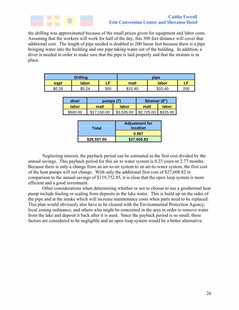
Caitlin Ferrell Erie Convention Center and Sheraton Hotel
26
the drilling was approximated because of the small prices given for equipment and labor costs. Assuming that the workers will work for half of the day, this 300 feet distance will cover that additional cost. The length of pipe needed is doubled to 200 linear feet because there is a pipe bringing water into the building and one pipe taking water out of the building. In addition, a diver is needed in order to make sure that the pipe is laid properly and that the strainer is in place.
Drilling pipe eqpt labor LF matl labor LF $0.28 $0.24 300 $10.40 $10.40 200
diver pumps (7) Strainer (8") labor matl labor matl labor
$500.00 $17,150.00 $3,535.00 $2,725.00 $325.00
Adjustment for location Total
0.967 $28,551.00 $27,608.82
Neglecting interest, the payback period can be estimated as the first cost divided by the
annual savings. This payback period for this air to water system is 0.23 years or 2.77 months. Because there is only a change from an air-to-air system to an air-to-water system, the first cost of the heat pumps will not change. With only the additional first cost of $27,608.82 in comparison to the annual savings of $119,752.85, it is clear that the open loop system is more efficient and a good investment.
Other considerations when determining whether or not to choose to use a geothermal heat pump include fouling or scaling from deposits in the lake water. This is build up on the sides of the pipe and at the intake which will increase maintenance costs when parts need to be replaced. This plan would obviously also have to be cleared with the Environmental Protection Agency, local zoning ordinance, and others who might be concerned in the area in order to remove water from the lake and deposit it back after it is used. Since the payback period is so small, these factors are considered to be negligible and an open loop system would be a better alternative.

Caitlin Ferrell Erie Convention Center and Sheraton Hotel
27
Acoustics - Sound Transmission through Guestroom Walls Introduction One major concern in hotels is the transmission of sound in between guestrooms. While it is assumed that the architects design for this issue, the actual study or result is not given. Comfort of the guests during their stay in the Erie Convention Center and Sheraton Hotel is vital to the success of the hotel. Because of this, it is important to make sure that the acoustics of the guestrooms are appropriate. This breadth study will calculate the total absorption of a typical guestroom of Type ‘A’. Using this and the transmission loss between two adjacent rooms of Type ‘A’, it can be determined whether or not the construction of the walls between the rooms is acoustically acceptable to block out the noise of humans talking in an adjacent room. Transmission Loss and Sound Absorption Two adjacent typical guestrooms of Type ‘A’ were analyzed to check for these acoustics requirements. The floor plans, along with the window dimensions for this room are shown in Figure 12.
Figure 12: Two adjacent guestrooms of Type ‘A’ are shown and dimensioned above. These dimensions, along with the window dimensions, will be used to estimate the sound transmission loss between the rooms.
The construction detail given in the architectural drawings shows that the wall in between guestrooms is constructed with two layers of 5/8” gypsum board (on each side), 3-5/8” metal studs, and 3” of fiberglass insulation. The sound transmission loss (TL) for various frequencies is given in the following table.

Caitlin Ferrell Erie Convention Center and Sheraton Hotel
28
Sound Transmission Loss (TL) for Frequencies (Hz) STC 125 250 500 1000 2000 4000 57 38 52 59 60 56 62 The materials used in the room have different absorption coefficients depending on how
porous the materials are. The sound absorptions and their corresponding surface areas for all surfaces of a room of Type ‘A’, including, walls, ceiling, floor, windows, and curtain are found in the tables below.
Sound Absorption Coefficients - α for Frequencies (Hz) Material 125 250 500 1000 2000 4000
(2) 5/8" gyp. Bd. On each side of 3-5/8" studs + fiberglass 0.1 0.07 0.05 0.05 0.04 0.04
Ceiling- CMU (painted) 0.1 0.05 0.06 0.07 0.09 0.08
Carpet, heavy, foam-backed 0.08 0.24 0.57 0.69 0.71 0.73
Glass Window 0.35 0.25 0.18 0.12 0.07 0.04
Fabric, 10 oz. velour, straight 0.03 0.04 0.11 0.17 0.24 0.35
Surface Areas (ft2) Material length height Area
Wall 1 25.33 9 227.97 Wall 2 12 9 71.93 Wall 3 25.33 9 227.97 Wall 4 12 9 108.00 Ceiling 25.33 12 303.96 Floor 25.33 12 303.96 Window 8.33 4.33 36.07 Fabric 8.33 4.33 36.07 Σ= 1315.93
To determine whether the noise reduction in between rooms will be enough, we will
consider one of the rooms to be a source, with people talking, and the other room to be a receiving room, the room in question. Using the surface areas and sound absorption coefficients found in the previous tables, the average sound absorption of the receiving room can be calculated for various frequencies, using the following equation: Arec=Σ(Sα)/ Σ S. Arec is the area

Caitlin Ferrell Erie Convention Center and Sheraton Hotel
29
of the receiving room, Σ(Sα) is the sum of the individual surface areas for a material times the absorption coefficients of that material, and Σ S is the total surface area of the room. The results for the average sound absorption are given in the table below.
Average Absorption Coefficient of Receiving Room
125 250 500 1000 2000 4000 0.1003 0.1088 0.1776 0.2077 0.2126 0.2171
Noise reduction is the change in sound pressure level of noise, and in this case, it is concerned with the reduction between a wall separating two guest rooms. Using the transmission loss through the wall, the area of the wall separating the space as well as the average absorption of the receiving room, the noise reduction can be found. The results are shown below.
Noise Reduction (NR) Between Rooms (dB) 125 250 500 1000 2000 4000 36 50 59 61 57 63
The following two tables give the sound pressure level in the source room due to people
talking at either a normal level, or in a raised voice. Subtracting the noise reduction through the wall will give the sound pressure level in the receiving room.
Voice Lp (Source Room)
125 250 500 1000 2000 4000 Normal Voice 53 59 63 58 50 47 Raised Voice 50 55 58 49 46 41
Lp (Receiving Room)
125 250 500 1000 2000 4000 Normal Voice 17 9 4 -3 -7 -16 Raised Voice 14 5 -1 -12 -11 -22
For people in the receiving room to not be able to hear noise from the adjacent room, the ambient sound in the receiving room needs to be approximately 5 dB above the sound pressure level in receiving room. Assuming that a window air conditioning unit provides the background noise, it can be seen by comparing the table below with the previous table, that the noise reduction in between walls is adequate.
Window AC Unit Sound Pressure - 5dB 125 250 500 1000 2000 4000 59 60 51 48 53 39

Caitlin Ferrell Erie Convention Center and Sheraton Hotel
30
In addition to the material construction of the wall, other construction techniques can be implemented to achieve positive results. The use of an acoustical sealant at the base of the wall can prevent sound from traveling through air space at the bottom of the wall. Also, because precast concrete planks are used, there is not an air plenum in between rooms. This eliminates the possibility of sound transmission through this area from one room to another.
I have concluded that the acoustic performance in between guestrooms is acceptable for the guest’s comfort. It was assumed that the source from the source room was people talking, however there could be other noises such as a television or radio turned on in addition. The noise reduction is so great, however, that these effects can be assumed to be negligible. Also, if the window air conditioning/heating unit is not turned on, there is a lack of ambient noise caused by the fan. In this case, there is a possibility of low frequency sound transmission through the walls, in which case a murmur could be heard.

Caitlin Ferrell Erie Convention Center and Sheraton Hotel
31
Summary and Conclusions The floor plan of the Erie Convention Center and Sheraton Hotel provided the opportunity to use a staggered truss system as an alternative design consideration for the structural system. The original structural system, a steel frame with a precast concrete plank floor system proved to be efficient for both cost and time scheduling, however, the staggered truss system, in the end was found to be even more efficient, as well as offering additional benefits. The trusses used in the staggered truss system create open spaces that are two bays wide. Even though on the upper floors this is not taken advantage of because of the use of the small guestrooms, the first floor is left completely open. This is especially beneficial in the dining room and conference areas. Within the staggered truss system, two floor systems were investigated: a precast concrete plank floor system, and a steel joist with steel deck and concrete slab floor system. Computer models using ETABS were created for both of these floor systems, and the members were sized. While the steel joist system sized some members slightly smaller than the model with the precast plank system, on average the member sizes were the same. In the end, the precast plank floor system was found to be the better alternative. The steel joist floor system would increase each floor height by one foot, creating an eleven foot increase in the total building height. This increase in height affects several factors negatively, including increased wind forces, increased cost of material for the exterior skin of the building, and changing the exterior architecture of the building. Using a steel joist floor system also provides the chance for increased floor vibrations, and more difficulty in fireproofing. Lake Erie provides a beautiful setting for the Erie Convention Center and Sheraton Hotel, however, it can also provide cost savings with the use of a geothermal heat pump. Using the water from the lake in an air-to-water open loop heat rejection system, the electricity used to heat and cool the building are decreased by almost $120,000 a year. After determining the first cost of installing the pipe and pump to take water from the lake, it was found that only a 3 month payback period will be needed. This system is extremely efficient and cost effective. Acoustics and sound transfer between guestrooms is a concern in any hotel, however with no analysis results provided, it is not certain that the noise reduction between the rooms is enough for the comfort of the guests. By calculating the transmission loss between rooms, as well as the absorption and noise reduction, it can be determined whether or not human voices can be heard through the walls and above ambient noise such as an air conditioner. A full analysis proves that the wall construction between two typical rooms is acceptable for the acoustic requirements expected. The Erie Convention Center and Sheraton Hotel was designed with the design requirements of a standard hotel construction. Overall, however, there are adjustments that could have been made to the structural and mechanical systems in order to make the building more cost efficient. In conclusion, looking beyond standard construction and design processes can open a whole new world of possibilities to make a building as efficient as possible.

Caitlin Ferrell Erie Convention Center and Sheraton Hotel
32
References Staggered Truss System Research and Design: AISC Steel Design Guide Series: (14) Staggered Truss Framing Systems. 2002 American Institute of Steel Construction. Manual of Steel Construction – Load And Resistance Factor Design, 3rd Edition. 2001 American Society of Civil Engineers. ASCE Standard 7-02 – Minimum Design Loads for Buildings and Other Structures. 2003 International Code Council. International Building Code 2003. 2002 PCI Design Handbook. 2005 The New Columbia Joist Company. Steel Joists and Joist Girders. 2002 United Steel Deck. Design Manual and Catalog of Products. 2002 “Benefits of Staggered Truss Systems in Multi-Story Residential and Other Applications.” Architectural Record. 2006.
<http://archrecord.construction.com/resources/conteduc/archives/0202aisc-1.asp> Cohen, Michael P. “Design Solutions Utilizing the Staggered-steel Truss System”, 1986 <http://www.aisc.org/Content/ContentGroups/Documents/Engineering_Journal4/265_EJ _cohen.pdf> Hassler, Arthur E. “Erecting the Staggered-truss System: A View from the Field”,
<http://www.aisc.org/Content/ContentGroups/Documents/Engineering_Journal4/266_EJ _hassler.pdf> Scalzi, John B. “The Staggered Truss System-Structural Considerations”, 1971
<http://www.aisc.org/Content/ContentGroups/Documents/Engineering_Journal4/263_EJ _scalzi.pdf> Mechanical: Energy Information Administration <http://www.eia.doe.gov/cneaf/electricity/epm/table5_6_a.html> Worthington Pump. Pump Selector for Industry. R.S. Means Mechanical Construction Cost Data 2005. Acoustics: Mehta, Johnson, Rocafort. Architectural Acoustics: Principles and Design. Upper Saddle River, NJ: Prentice Hall, 1999 Egan, M. David. Architectural Acoustics. New York, NY: McGraw-Hill, Inc., 1988

Caitlin Ferrell Erie Convention Center and Sheraton Hotel
33
Acknowledgements
I would like to extend my thanks to Angelo Maione, John Schneider, and Andy Verrengia of Atlantic Engineering Services for their aid in the selection of my thesis building, and providing me with the drawings of the Erie Convention Center and Sheraton Hotel. I would also like to thank Dr. Boothby, my thesis advisor, and Professor Parfitt for their help in my selection of a thesis topic and answering all of my questions along the way. In addition, I would like to thank the members of the thesis discussion board for their help and advice, especially Charlie Carter. Finally, I would like to thank all of my friends for their support, advice, and daily trips to McLanahan’s.

Caitlin Ferrell Erie Convention Center and Sheraton Hotel
I
Appendices
Appendix 1: Precast Plank Design Appendix 2: Steel Joist Floor System Design Appendix 3: Staggered Truss Member Sizes

Caitlin Ferrell Erie Convention Center and Sheraton Hotel
II
Appendix 1 : Precast Plank Design
Caitlin Ferrell Erie Convention Center and Sheraton Hotel
III
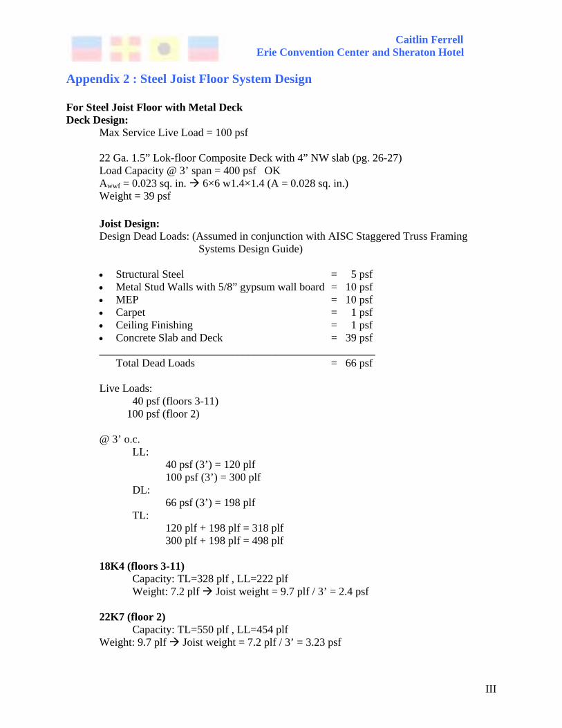
Appendix 2 : Steel Joist Floor System Design For Steel Joist Floor with Metal Deck Deck Design: Max Service Live Load = 100 psf 22 Ga. 1.5” Lok-floor Composite Deck with 4” NW slab (pg. 26-27) Load Capacity @ 3’ span = 400 psf OK Awwf = 0.023 sq. in. 6×6 w1.4×1.4 (A = 0.028 sq. in.) Weight = 39 psf Joist Design:
Design Dead Loads: (Assumed in conjunction with AISC Staggered Truss Framing Systems Design Guide)
• Structural Steel = 5 psf • Metal Stud Walls with 5/8” gypsum wall board = 10 psf • MEP = 10 psf • Carpet = 1 psf • Ceiling Finishing = 1 psf • Concrete Slab and Deck = 39 psf __________________________________________________ Total Dead Loads = 66 psf Live Loads: 40 psf (floors 3-11) 100 psf (floor 2) @ 3’ o.c. LL: 40 psf (3’) = 120 plf 100 psf (3’) = 300 plf DL: 66 psf (3’) = 198 plf TL: 120 plf + 198 plf = 318 plf 300 plf + 198 plf = 498 plf 18K4 (floors 3-11) Capacity: TL=328 plf , LL=222 plf Weight: 7.2 plf Joist weight = 9.7 plf / 3’ = 2.4 psf 22K7 (floor 2) Capacity: TL=550 plf , LL=454 plf
Weight: 9.7 plf Joist weight = 7.2 plf / 3’ = 3.23 psf
Caitlin Ferrell Erie Convention Center and Sheraton Hotel
IV
Appendix 3 : Staggered Truss Member Sizes
Spandrel Beams (Plank) Floor Shape Number Linear Feet Weight Tot. Wt.
1 W21x55 4 101.32 55 5572.6 W36x150 4 100 150 15000 W36x182 6 150 182 27300 2 W21x68 10 250.66 68 17044.88 W24x76 4 100.66 76 7650.16 3 W21x55 14 351.34 55 19323.7 4 W21x55 14 351.34 55 19323.7 5 W21x55 14 351.34 55 19323.7 6 W21x55 14 351.34 55 19323.7 7 W21x55 14 351.34 55 19323.7 8 W21x55 14 351.34 55 19323.7 9 W21x55 14 351.34 55 19323.7
10 W18x50 14 351.34 50 17567 11 W18x50 14 351.34 50 17567
Σ= 242968

Caitlin Ferrell Erie Convention Center and Sheraton Hotel
V

Caitlin Ferrell Erie Convention Center and Sheraton Hotel
VI
Caitlin Ferrell Erie Convention Center and Sheraton Hotel
VII
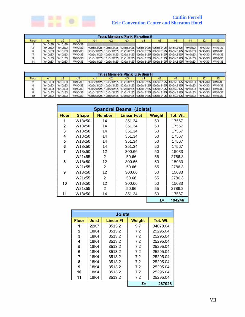
Spandrel Beams (Joists)
Floor Shape Number Linear Feet Weight Tot. Wt. 1 W18x50 14 351.34 50 17567 2 W18x50 14 351.34 50 17567 3 W18x50 14 351.34 50 17567 4 W18x50 14 351.34 50 17567 5 W18x50 14 351.34 50 17567 6 W18x50 14 351.34 50 17567 7 W18x50 12 300.66 50 15033 W21x55 2 50.66 55 2786.3 8 W18x50 12 300.66 50 15033 W21x55 2 50.66 55 2786.3 9 W18x50 12 300.66 50 15033 W21x55 2 50.66 55 2786.3
10 W18x50 12 300.66 50 15033 W21x55 2 50.66 55 2786.3
11 W18x50 14 351.34 50 17567 Σ= 194246
Joists
Floor Joist Linear Ft Weight Tot. Wt. 1 22K7 3513.2 9.7 34078.04 2 18K4 3513.2 7.2 25295.04 3 18K4 3513.2 7.2 25295.04 4 18K4 3513.2 7.2 25295.04 5 18K4 3513.2 7.2 25295.04 6 18K4 3513.2 7.2 25295.04 7 18K4 3513.2 7.2 25295.04 8 18K4 3513.2 7.2 25295.04 9 18K4 3513.2 7.2 25295.04
10 18K4 3513.2 7.2 25295.04 11 18K4 3513.2 7.2 25295.04
Σ= 287028
Caitlin Ferrell Erie Convention Center and Sheraton Hotel
VIII

Caitlin Ferrell Erie Convention Center and Sheraton Hotel
IX
Caitlin Ferrell Erie Convention Center and Sheraton Hotel
X