Embed Size (px)
Citation preview
National Aerospace Laboratory NLRNational Aerospace Laboratory NLRNational Aerospace Laboratory NLRNational Aerospace Laboratory NLR
Technical University DelftTechnical University DelftTechnical University DelftTechnical University Delft
NLR-CR-2007-200
CAED D2: Modelling the Turnaround ProcessCAED D2: Modelling the Turnaround ProcessCAED D2: Modelling the Turnaround ProcessCAED D2: Modelling the Turnaround Process
CARE INO III: The Co-ordinated Airport through
Extreme Decoupling
P. van Leeuwen
No part of this report may be reproduced and/or disclosed, in any form or by any means without the prior written permission of the owner.
Customer: Eurocontrol Contract number: 2366111 Owner: Eurocontrol Date: 19 April 2007 Version: 2.0

-2-
CAED D2: MODELLING THE TURNAROUND

-3-
CAED D2: MODELLING THE TURNAROUND
Summary
This document provides the operational context for the Co-ordinated Airport through Extreme
Decoupling (CAED). In the first chapter, the Collaborative Decision Making background of the
project is sketched, as well as its relation to Total Airport Management. Next, the turnaround
process is introduced in general terms.
In the second chapter, the turnaround process is further elaborated by describing the various
ground handling processes to be performed during turnaround. Additionally, the relation
between ground handling and stand planning is detailed. Finally, the importance of ground
handling for punctuality and efficiency in airport operations is discussed.
In the third chapter, an outline is presented for a general model of the turnaround process. The
planning problem addressed is described, as well as the actors, tasks and resources to be
included in the model. Furthermore, the boundaries and limitations of the model are drawn by
explicating the underlying assumptions.
In the fourth chapter, the model described in chapter 3 is given more contents. By means of an
operational example, this chapter illustrates how the ground handling model can be applied in
practice. The example is translated step by step into a Simple Temporal Network (STN)
representation, which in turn is decoupled into local ground handlers’ sub-networks. A set of
solutions to these decoupled networks is proposed.

-4-
CAED D2: MODELLING THE TURNAROUND
Contents
1 Introduction 6
1.1 CDM and Total Airport Management 6
1.2 Extreme Decoupling 7
1.3 The Airport Turnaround Process 9
2 Ground Handling Processes 12 2.1 Why focus on Ground Handling? 12
2.2 The Ground Handling Processes in Detail 13
2.2.1 Docking 13
2.2.2 De-boarding 13
2.2.3 Baggage and cargo unloading 14
2.2.4 Security 14
2.2.5 Cleaning 14
2.2.6 Fuelling 14
2.2.7 Catering 14
2.2.8 Baggage and cargo loading 14
2.2.9 Passenger boarding 15
2.2.10 Security 15
2.2.11 Aircraft check 15
2.2.12 Push-back 15
2.3 Ground Handling and Stand Planning 16
2.3.1 Stand Planning per Planning Phase 16
2.3.2 Involvement of Ground Handlers in Stand Planning 17
3 Towards a Model of Ground Handling 19
3.1 The planning problem addressed 19
3.1.1 The Planning Phase 20
3.1.2 Actors, Tasks and Resources 20
3.2 Limitations of the Domain, Assumptions 22
3.3 Goals of the Model per Project Phase 25
3.4 High-level Description of the Model 26
4 A Ground Handling Example 28 4.1 Constructing a Model of the Domain 28
4.2 Decoupling the Domain Model 36

-5-
CAED D2: MODELLING THE TURNAROUND
4.3 Solving the Decoupled Planning Problems 40
5 Conclusions and Future Work 44
6 References 46 6.1 Document References 46
6.2 Online references 47
Appendix A Airplane Servicing Arrangements for the B737-300 and MD11 48
Appendix B Airplane Terminal Operations for B737-300 and MD11 50
(51 pages in total)
-6-
CAED D2: MODELLING THE TURNAROUND
1 Introduction
This document describes the operational context addressed by the Co-ordinated Airport through
Extreme Decoupling (CAED) project. In this project, a general methodology is developed to
support the integration of local planning functions into an encompassing, total airport planning.
Central to this approach is the assumption that local parties are in the best position to plan their
own resources and activities. Based on this assumption, a methodology called ‘extreme
decoupling’ is investigated to ensure that – given an initial airport plan – local plans can be
established and merged again into a conflict-free total airport plan.
In this chapter, first the context of the research project is outlined. Next, extreme decoupling is
described as the airport planning methodology central to this project. Finally, a short overview
is sketched of the operational process to which extreme decoupling will be applied.
1.1 CDM and Total Airport Management
Collaborative Decision Making (CDM) has been identified as an important enabler of capacity
and efficiency [CDM Handbook]. CDM addresses the need for operational decisions to be made
collaboratively to provide a common situational awareness for ATC, airlines, airports, handlers
and other partners involved. It is about improving the way the different stakeholders in the
ATM system work together at an operational level.
Of course, collaboration between different parties has to some extent always existed. However,
until now the collaboration in ATM has been more of an ad-hoc and human-centred process.
CDM can be seen as a philosophy in ATM that emphasises the importance of collaboration in
planning and managing air traffic. In effect, CDM tries to replace the current central planning
paradigm with a collaborative paradigm. To establish such a paradigm, information owned by
individual actors is given free for all (in a useful system-wide representation). Access of all
parties in ATM to sets of up-to-date information creates a common situational awareness. Thus,
all actors involved will know better what goes on at a global level, improving their means to
commonly reach a better overall planning.
A following step after CDM is Total Airport Management (TAM), which encapsulates CDM
and brings a planning and decision support component to it [TAM]. Although airports, airlines,
and ATC service providers try to optimise the efficiency of their local planning systems, there is
little effort directed towards the real integration of these planning systems and procedures so as
to maximise the performance of the entire airport system. This situation prevents optimal use of
the available capacity, both at airports and in terminal area airspace. Total Airport Management
-7-
CAED D2: MODELLING THE TURNAROUND
addresses this problem. The operational scope of TAM ranks from strategic decision making, on
the one hand, to pre-tactical and tactical planning and decision making processes, on the other
hand.
European CDM is mostly focussed on the airport processes around ATC. It has been recognised
that for Total Airport Management, a broader scope, including airport and airline processes is
necessary. In this document, we focus on the airport turnaround processes. Although turnaround
management has played a part in research in the past (e.g., Gate-to-Gate [G2G], Airport Airside
Management [AAM]), its detailed processes, responsible parties and complicated links to other
airport processes have not yet been subjected to extensive research. By further explicating these
processes and by integrating them with the overall planning and decision making processes at
airports, this research aims to make a significant contribution to the further development of
Total Airport Management.
1.2 Extreme Decoupling
The integration of ground services and turnaround management with the overall airport
planning will be procured by means of a methodology called ‘Extreme Decoupling’. This
methodology, central to the CAED project, tries to overcome most of the above mentioned
planning problems at airports (see section 3.1 for further details). To do so, a balance is sought
between two extreme solutions to airport planning problems: fully centralised planning, and
fully distributed planning.
When aiming at fully centralised planning, serious problems arise. For instance, central
planning would require central planning tools to support the entire decision making process.
Such central planning tools, however, will not be technically feasible since they would have to
incorporate all planning constraints, regulations, schedules, and resources of all parties active at
the airport. Reaching an acceptable planning solution in real time is then not an option.
Another problem in centralised planning stems from the organisation of operational processes at
airports. Since many parties are active, having their own expertise, information, interests, and
business model, they may not be willing to subordinate themselves to a central decision making
process. In CDM terms: local parties are in the best position to take decisions. Most of the
knowledge, know-how and expertise resides locally, and many parties may not be willing or
able to explicate or share this local expertise with others in a central planning procedure.
To resolve these problems, a fully distributed planning process may be proposed. In this way,
decision making is distributed amongst all parties, sharing relevant information with others to
-8-
CAED D2: MODELLING THE TURNAROUND
reach a common planning solution. Unfortunately, this approach has its disadvantages as well.
In projects such as the Fifth Framework project LEONARDO, for instance, it turned out that the
co-ordination mechanism required to reach a common solution for any type of planning conflict
was extremely complex [LEO]. For this reason, the project limited itself to a small number of
pre-established conflicts.
Apart from complexity, another problem arose. In the distributed decision support system, a
central planning ‘agent’ was still required to decide which parties should resolve a given
conflict, and what solution was to be chosen. Thus, although fully distributed, the decision
support tool still violated the autonomy of the parties involved.
For this reason, the approach taken in the CAED project tries to combine the best of two worlds.
Central planning does not acknowledge the desire of local parties to plan their activities
themselves (as much as possible). Moreover, the airport’s human organisation in parties
responsible for their own processes is not respected. A fully distributed system, on the other
hand, may still require central co-ordination for each planning activity – thus violating the
decision maker’s autonomy. Furthermore, a fully coupled system may lead to insurmountable
co-ordination problems resulting from its complexity in practice. In conclusion, the CAED
project aims not to couple different planning functions to one another, but – on the contrary – to
entirely decouple these planning functions. Hence the term ‘Extreme Decoupling’.
The extreme decoupling approach can be described in three steps. First, overall planning
constraints for a given airport domain are ‘decoupled’ from this domain and distributed amongst
the underlying local planning domains. These constraints can be of any type: traffic regulations,
slot constraints, resource limitations, etc. In this document, the stand allocation plan is chosen as
the overall airport domain, whereas the local planning domains correspond to the ground
handlers involved in the turnaround.
Second, given these additional constraints, the local planners can make their planning without
further co-ordination with other planners, or with the Airport Authorities / Airline. In other
words, no communication overhead (with corresponding complexity) arises: given the
decoupled constraints, added to their local planning domain, the planners (e.g., the fuelling
company, boarding operator, caterer) can do their planning independently according to their
own insights, business model, and planning methods.
Third, the resulting local plans can be merged together into an overall plan for the given airport
domain. For instance, for the turnaround domain, the stand allocation plan will then be
completed by a detailed ground services plan yielding an overall stand & services plan. Given

-9-
CAED D2: MODELLING THE TURNAROUND
certain properties of the decoupling algorithm (further detailed in [D1]), the merged solution is
guaranteed to be conflict-free.
1.3 The Airport Turnaround Process
In the CAED project, this extreme decoupling methodology will be applied to the airport
turnaround process. The airport turnaround process comprises all ground handling activities that
need to be performed at an aircraft when parked at a stand1. These activities need to be
performed between in-block, when the aircraft arrives at the stand, and off-block, when the
aircraft leaves the stand. Example ground handling services are: baggage and cargo (un)loading,
the (de-)boarding of passengers and crew, cleaning, catering, fuelling, and aircraft technical
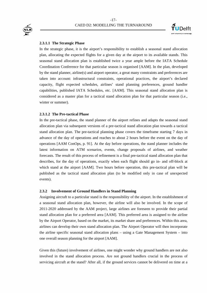
services. Figure 1 gives an overview of all services and corresponding equipment that are
involved in the turnaround process of an aircraft at the stand.
Figure 1: Aircraft at the stand
In this figure, the aircraft is docked at the pier. The following vehicles / equipment are shown:
A. Push-back vehicle
B. Vehicles for catering (galley services)
C. Vehicle for unloading and loading of freight and mail
D. Bulk cargo/baggage trailers
1 In this report, the terms turnaround processes and ground handling processes/services are used interchangeably. Note further
that the term ‘stand’ is used for both stands and gates.

-10-
CAED D2: MODELLING THE TURNAROUND
E. Fuel truck
F. Cleaning vehicle
G. Potable water and lavatory vehicle
H. Passenger bridge
I. Electrical cart
The exact number and position of these vehicles and equipment depend on the aircraft type, and
the stand (remote stand, gate at the pier). Appendix A shows the exact airplane servicing
arrangement for the two example aircraft types that will be used throughout this document: a
Boeing 737-300 and a McDonnell Douglas 11.
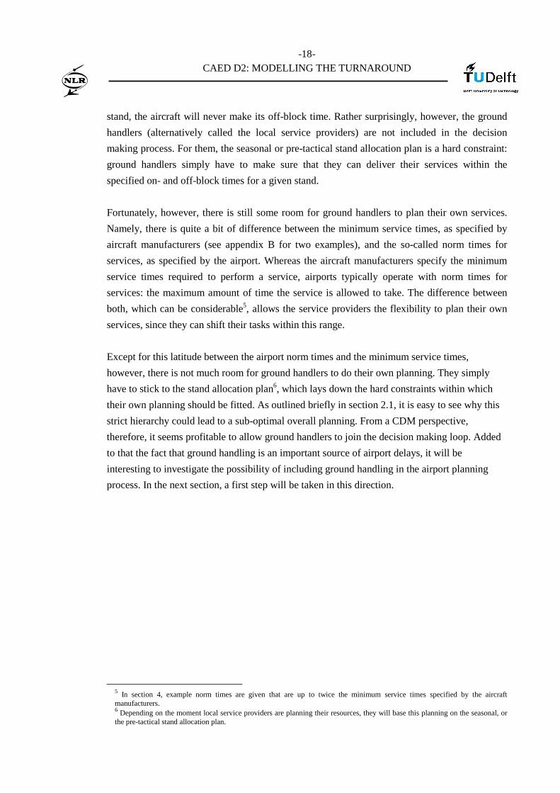
Obviously, there is a lot of planning involved to make sure that these services are performed in
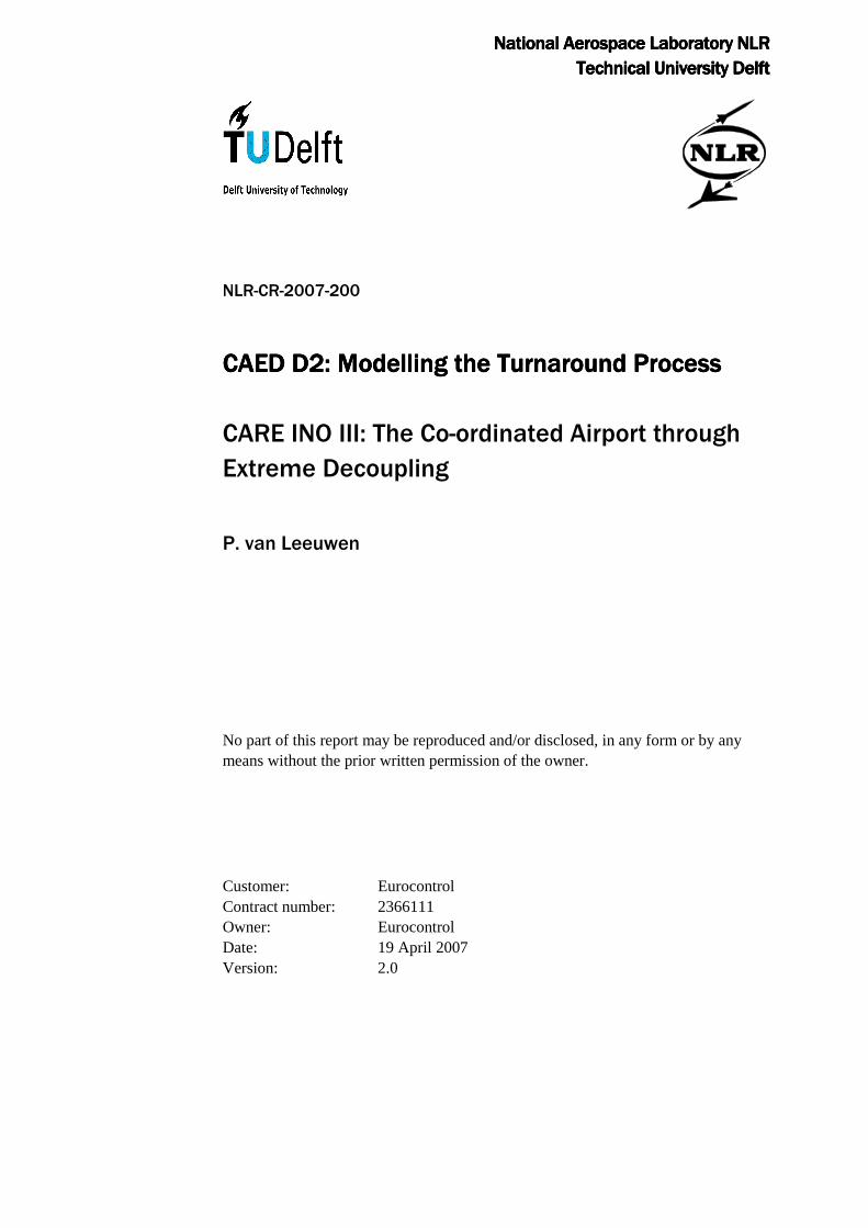
time – without getting into each other’s way. Figure 2 gives a high-level overview of the flow of
ground handling services between on- and off-block. In this figure, the ground handling services
have been divided into four different, parallel flows: the baggage and cargo processes, the
passenger and cabin processes, the fuelling processes, and the aircraft technical services
(typically only involving small maintenance and aircraft checks). Most of these activities can be
undertaken simultaneously. Note that these processes need to be further subdivided into one or
more sub-processes. The arrows in the figure indicate the required order of activities.
Figure 2: Workflow of the Turnaround Processes
Boarding passengers and
crew
De-boarding passengers and crew
Aircraft technical
Off-blocks
In-blocks
Cleaning and catering
Passenger and cabin flow
Baggage en cargo
unloading
Baggage en cargo
loading
Baggage and cargo flow
Fuelling
Aircraft handling
Fuel flow
-11-
CAED D2: MODELLING THE TURNAROUND
The above processes can be further subdivided and related to the arrival part and the departure
part of a flight during turnaround. In this manner, the following ground services can be
distinguished:
• Arrival:
o docking
o de-boarding of passengers and crew
o baggage and cargo unloading
o security
• Departure:
o cleaning
o fuelling
o catering
o baggage and cargo loading
o passenger boarding
o security
o aircraft check
o push-back/tow away
Every aircraft type has a minimum turnaround time. The turnaround time depends on the
number and complexity of processes that need to be performed. Turnaround time will be longer
for larger aircraft or for airlines that provide more service (e.g. magazines, newspapers, meals)
to their passengers.
This chapter presented a brief overview of the CDM and TAM context of this research. Extreme
decoupling has been outlined as the focal planning methodology, and the turnaround process
was introduced. In the next chapter, this turnaround process will be described in further detail.
-12-
CAED D2: MODELLING THE TURNAROUND
2 Ground Handling Processes
In this chapter, the ground handling processes constituting turnaround will be further elaborated.
Also, the relation between these processes and other airport processes will be outlined. But first,
an important question needs to be addressed. Why is ground handling such an interesting
candidate for further research?
2.1 Why focus on Ground Handling?
Before getting into detail about the relationship between ground handling and other airport
processes (see section 2.3 below), it should be stressed that ground handlers do not have much
room to do their own resource planning. Ground handling should take place within the
turnaround time, meaning that all ground services need to be planned within a pre-determined
on- and off-block of aircraft. Ground handlers thus have to stick to these times, laying down the
hard constraints within which their own planning should be fitted. One can easily see why this
strict hierarchy could lead to a sub-optimal overall planning. For instance, when a fuelling
company has to fuel five aircraft at pier A, one at pier D and another five at pier A, it could be
very profitable for the fuelling company to suggest a gate change for the one aircraft at pier D
(especially if this pier is at the other side of the airport). Under certain circumstances, it may
indeed be possible to allow such a gate change. The problem with the current way of operating
is that the fuelling company does not have a say in the process of allocating stands2 to aircraft,
or changing stand allocations – as we shall see in section 2.3 below.
From a CDM perspective, then, it seems profitable to allow ground handlers to join the decision
making loop for allocating stands to aircraft. It would mean putting the power in the hands of
the party best placed to take the decisions, enhancing each partner’s commitment to the
established allocation plan. Moreover, the overall efficiency of the stand allocation plan will
increase when all parties involved in turnaround actually participate, which in turn has a
positive effect on other airport processes. After all, turnaround is (literally) a pivoting process in
airport planning.
But there are other reasons for focusing on ground handling. As stated in the introduction,
although turnaround management has played a part in much research in the past, its detailed
processes, responsible parties and complicated links to other airport processes have not yet been
2 The term ‘stand’ will be used for both gates and remote stands throughout this document.

-13-
CAED D2: MODELLING THE TURNAROUND
the subject of extensive research3. Thus, the field is relatively new and may yield interesting
improvements to total airport management.
Finally, ground handling is recognised as a common and important source of delays in the air
transport system. According to research conducted at London Gatwick Airport, ground handling
services are the second largest contributor to flight delays, right after air traffic control (ATC)
related delays. In this research, ground handling services proved to be responsible for 25 percent
of all delays at London Gatwick [Wu et al, 2004b, 2000]. Ground handling delays typically lead
to delays in other airport processes – not only for the delayed aircraft itself (knock-on delays),
but also for other aircraft, whether inbound, outbound or docked at other stands.
Thus, the performance of aircraft turnaround operations has a strong impact on the punctuality
of the totality of airline operations. Punctuality, in turn, strongly influences the choice of
passengers for selecting a certain airline company [Wu et al, 2004a] and thus plays an important
role in the success of airlines. By improving ground handling operations, therefore, we hope to
improve the punctuality of the entire air transport system. This will most certainly have a
positive effect on the operations of all airport partners involved.
2.2 The Ground Handling Processes in Detail
Having underlined the importance of research into ground handling, this section will describe
the different ground handling processes in detail. As much as possible, alternative options for
carrying out a given task are described. For further details the reader is referred to [IATA,
2004]. In this airport handling manual, the network of airport business processes at the airport’s
ground surface is described in great detail.
2.2.1 Docking
Docking is the arrival at the exact location for arranging the handling processes. As pilots are
not able to see the location of their wheels, a flagger is necessary to signal the crew how to
move and where exactly to stop. At many airports, the flagger is replaced by an automated
docking system, where on the wall in front of the aircraft, electronic signals indicate to the pilot
what to do.
2.2.2 De-boarding
De-boarding starts with bringing an aviobridge or stairs to the aircraft.
3 Apart from the link to departure, arrival, stand and taxiway planning, modelling the turnaround process may also help to gain insight in the connection between airside and landside processes. After all, it is during turnaround that these distinct perspectives on airport processes meet.
-14-
CAED D2: MODELLING THE TURNAROUND
In case passengers and crew de-board via stairs, additional airport personnel is necessary to
guide them to the buildings. This can be a brief walk over the airport’s surface or through a bus
connection. The crew gets a special treatment as they will leave after the passengers and need
more time for final checks.
2.2.3 Baggage and cargo unloading
Baggage unloading can typically start almost immediately after the aircraft has come to a stop.
A dedicated company will take out the baggage and bring this to the terminal building.
Cargo, if not too voluminous, is unloaded at the aircraft’s stand. More commonly, cargo from
combi-aircraft is unloaded at the airport’s cargo area, in which case the aircraft will be towed to
that position with a tow vehicle.
2.2.4 Security
Aircraft with passengers from certain countries need a security check when they arrive at an
airport.
2.2.5 Cleaning
Cleaning concerns the interior of the aircraft, which is prepared for the following flight.
2.2.6 Fuelling
Fuelling is performed with pump vehicles, which take the kerosene from hydrant wells, which
are located at the gates. Alternatively, tank vehicles bring the fuel to the aircraft.
2.2.7 Catering
Catering delivers the necessary food to the aircraft. Depending on the destination of a flight,
certain types of food are not allowed. Some airlines allow passengers to indicate special wishes
(like vegetarian meals) beforehand.
Several airlines do not serve food to every passenger; instead they provide food and drinks at a
cost. In this case, fewer catering items will be required.
2.2.8 Baggage and cargo loading
Like cargo unloading, if necessary, cargo loading is performed at the cargo area. Specific rules
exist concerning live stock and cooling. These are not allowed to wait at the cargo area too long.
Baggage loading is handled at the stand.

-15-
CAED D2: MODELLING THE TURNAROUND
2.2.9 Passenger boarding
Passengers can board the way they de-board, either through an aviobridge, through a short walk
on the surface or through a bus connection.
2.2.10 Security
All passengers and their luggage have to pass a security check. If this is performed at the gate,
the process is included in the handling process.
At some airports, the security check is performed at a central area. In this case, the security
check is not included in the handling process.
2.2.11 Aircraft check
The crew is responsible for the flight and will check the aircraft thoroughly before each flight.
Aircraft checks concern inspections on the outside of the aircraft and proper functioning of the
aircraft machinery and equipment (checks in the cockpit).
2.2.12 Push-back
When all boarding processes have been completed, the aircraft can depart. Aircraft at gates need
to be pushed-back using dedicated push-back vehicles. Aircraft at stands mostly require a push-
back as well, depending on the configuration of the stand. At some stands, aircraft can directly
start up their engines and start taxiing.
Push-back is a link between the handler, the airline, and ATC.
2.2.12.1 ATC related
Push-back is part of the departure management process of ATC (at some airports the airport
authority is responsible). Usually, a dedicated push-back (and start-up) controller is assigned for
this task. Push-back must be organised so that departure slots are realised and/or that the
sequence which is proposed by the departure manager (if available) is established.
A few airports already implement the pre-departure sequencing procedure as proposed by
EUROCONTROL (currently Brussels and Munich are the farthest in this). This procedure
requires from airlines that an aircraft ready time (ERDT or TOBT = Target Off Block Time) is
provided to ATC, approximately 30 minutes before the aircraft will be ready for push-back.
This enables ATC to plan the push-back events, using a pre-departure sequencing tool.

-16-
CAED D2: MODELLING THE TURNAROUND
2.2.12.2 Handler-related
Push-back is performed by special companies that own the push-back vehicles. Different types
of vehicles exist:
• Vehicles with tow-bar (conventional tugs). These vehicles attach a bar between the
aircraft’s nose wheel and the vehicle, after which the aircraft is pushed backwards.
• Vehicles that lift the aircraft (modern tugs). The aircraft is tilted onto the vehicle and then
pushed backwards. This procedure is much quicker than the tow-bar because no manual
actions to connect the aircraft to the vehicle have to be performed.
Two sizes of push-back vehicles exist: for smaller and larger aircraft. Some vehicles can only
push aircraft, while other can push and pull/tow. For towing operations, to move an aircraft to
another position, a pull tug is necessary. For pulling an aircraft, two people are needed: one to
operate the vehicle and an additional technician in the cockpit. For push only, the vehicle can be
operated by one person.
2.3 Ground Handling and Stand Planning
A next question that could be raised is how the processes detailed in section 2.2 are related to
the overall airport planning processes. In this section, the most important related process chain
will be described: stand planning4. Other airport processes, such as arrival management, taxi
management, and departure management, are also related to and dependent on the turnaround of
aircraft. Nevertheless, these processes are not as closely linked to ground handling and will
therefore not be discussed in this document. Deliverable D3 of this project, however, will sketch
a more detailed picture of the relation between ground handling and other airport processes.
2.3.1 Stand Planning per Planning Phase
Obviously, ground handling is not isolated from other processes taking place at an airport. The
most important process chain, with which ground handling is thoroughly intertwined, is the
process of stand planning. In this process, an initial stand plan is developed based on the
airlines’ preferences and the airport’s stand availability. This is typically done half a year in
advance, yielding a so-called seasonal stand allocation plan. Next, this seasonal stand allocation
plan will be refined step by step towards the day of operations. Below, this process will be
described in further detail and related to two planning phases: strategic and pre-tactical.
4 Stand planning is an airport process concerned with the establishment of a so-called stand allocation plan. This stand allocation
plan describes how aircraft are assigned to their stands for a given time period for that airport. A stand allocation plan includes in-block and off-block time estimates and will be established for a particular day of operation.
-17-
CAED D2: MODELLING THE TURNAROUND
2.3.1.1 The Strategic Phase
In the strategic phase, it is the airport’s responsibility to establish a seasonal stand allocation
plan, allocating the expected flights for a given day at the airport to its available stands. This
seasonal stand allocation plan is established twice a year ample before the IATA Schedule
Coordination Conference for that particular season is organised [AAM]. In the plan, developed
by the stand planner, airline(s) and airport operator, a great many constraints and preferences are
taken into account: infrastructural constraints, operational practices, the airport’s declared
capacity, flight expected schedules, airlines’ stand planning preferences, ground handler
capabilities, published IATA Schedules, etc. [AAM]. This seasonal stand allocation plan is
considered as a master plan for a tactical stand allocation plan for that particular season (i.e.,
winter or summer).
2.3.1.2 The Pre-tactical Phase
In the pre-tactical phase, the stand planner of the airport refines and adapts the seasonal stand
allocation plan via subsequent versions of a pre-tactical stand allocation plan towards a tactical
stand allocation plan. The pre-tactical planning phase covers the timeframe starting 7 days in
advance of the day of operations and reaches to about 2 hours before the event on the day of
operations [AAM ConOps, p. 91]. At the day before operations, the stand planner includes the
latest information on ATM scenarios, events, change proposals of airlines, and weather
forecasts. The result of this process of refinement is a final pre-tactical stand allocation plan that
describes, for the day of operations, exactly when each flight should go in- and off-block at
which stand at the airport [AAM]. Two hours before operation, this pre-tactical plan will be
published as the tactical stand allocation plan (to be modified only in case of unexpected
events).
2.3.2 Involvement of Ground Handlers in Stand Planning
Assigning aircraft to a particular stand is the responsibility of the airport. In the establishment of
a seasonal stand allocation plan, however, the airline will also be involved. In the scope of
2011-2020 addressed by the AAM project, large airlines are foreseen to provide their partial
stand allocation plan for a preferred area [AAM]. This preferred area is assigned to the airline
by the Airport Operator, based on the market, its market share and preferences. Within this area,
airlines can develop their own stand allocation plan. The Airport Operator will then incorporate
the airline specific seasonal stand allocation plans – using a Gate Management System – into
one overall season planning for the airport [AAM].
Given this (future) involvement of airlines, one might wonder why ground handlers are not also
involved in the stand allocation process. Are not ground handlers crucial in the process of
servicing aircraft at the stand? After all, if the ground services cannot be delivered on time at a
-18-
CAED D2: MODELLING THE TURNAROUND
stand, the aircraft will never make its off-block time. Rather surprisingly, however, the ground
handlers (alternatively called the local service providers) are not included in the decision
making process. For them, the seasonal or pre-tactical stand allocation plan is a hard constraint:
ground handlers simply have to make sure that they can deliver their services within the
specified on- and off-block times for a given stand.
Fortunately, however, there is still some room for ground handlers to plan their own services.
Namely, there is quite a bit of difference between the minimum service times, as specified by
aircraft manufacturers (see appendix B for two examples), and the so-called norm times for
services, as specified by the airport. Whereas the aircraft manufacturers specify the minimum
service times required to perform a service, airports typically operate with norm times for
services: the maximum amount of time the service is allowed to take. The difference between
both, which can be considerable5, allows the service providers the flexibility to plan their own
services, since they can shift their tasks within this range.
Except for this latitude between the airport norm times and the minimum service times,
however, there is not much room for ground handlers to do their own planning. They simply
have to stick to the stand allocation plan6, which lays down the hard constraints within which
their own planning should be fitted. As outlined briefly in section 2.1, it is easy to see why this
strict hierarchy could lead to a sub-optimal overall planning. From a CDM perspective,
therefore, it seems profitable to allow ground handlers to join the decision making loop. Added
to that the fact that ground handling is an important source of airport delays, it will be
interesting to investigate the possibility of including ground handling in the airport planning
process. In the next section, a first step will be taken in this direction.
5 In section 4, example norm times are given that are up to twice the minimum service times specified by the aircraft manufacturers. 6 Depending on the moment local service providers are planning their resources, they will base this planning on the seasonal, or the pre-tactical stand allocation plan.
-19-
CAED D2: MODELLING THE TURNAROUND
3 Towards a Model of Ground Handling
In this chapter, an outline is sketched to pave the way towards a general model of ground
handling. The planning problem addressed is described, as well as the actors, tasks, and
resources that will be included in the model. Furthermore, the boundaries and limitations of the
model are outlined by explicating the underlying assumptions. In deliverable D3 of the CAED
project, the preliminary model description offered in this chapter will be used as a baseline for
the development of a mature, formalized ground handling model.
3.1 The planning problem addressed
In ground handling, many different airport processes can be distinguished. For the coordination
of these processes, planning and scheduling play a crucial role. Sophisticated schedules have
been developed to meet the high efficiency requirements and deal with the limited availability
of resources for each airport process. Yet, even though the implementation of such specialised
planning software has led to a considerable performance gain, inefficiencies are still
encountered. This has to do with the dynamic and distributed nature of the domain, as well as
the requirement to coordinate actions between actors.
The planning problem central to the CAED project, of which this document forms part, can be
summarised as follows. How can multiple actors, operating in a highly dynamic and distributed
environment, plan their activities independently whilst still assuring that the combined overall
plan is consistent? In the new planning approach proposed here, it is recognised that every actor
depends on the actions of other actors – but typically prefers to plan his own processes as much
as possible. After all, each actor has his own goals, resources, performance issues, and business
objectives. Applied to the ground handling domain, it is clear that many different companies are
responsible for the safe and expedient handling of aircraft during turnaround. In the approach
proposed here, these handlers are allowed to plan their processes locally as much as possible.
Such processes can be modelled as temporal problems. In [D1], examples have been given of
simple and extended temporal models. Also, temporal decoupling has been described as a
general technique to decouple a large planning domain into sub-domains suited for local
planning. In this chapter, the temporal and decoupling theory will be applied to the domain of
ground handling. A preliminary model of ground handling will be sketched based on the
processes distinguished in section 2. As a first step, these processes will be further refined
below in terms of the planning phases addressed and the actors, tasks and resources involved.
-20-
CAED D2: MODELLING THE TURNAROUND
3.1.1 The Planning Phase
In airport planning, typically three different planning layers or horizons are distinguished: the
strategic, pre-tactical, and tactical planning layer. By convention, task scheduling and resource
utilisation is (re)planned at each layer – although, of course, there are many dependencies
between the different layers. In our model, two planning layers are of particular interest – as we
saw in section 2.2. First, the strategic planning layer determines the initial stand allocation that
forms the baseline for all subsequent planning. At the slot conferences in March and September,
about half a year before flight, the basis is laid for a seasonal stand allocation plan that
establishes the slots in which all ground handling needs to take place. Therefore, all planning
addressed by our model can only start after all strategic planning, resulting in a confirmed
seasonal stand allocation plan, is finished.
On the other hand, the ground handling services should be planned before the actual flight. As
explained in section 2, the tactical stand plan is published about 2 hours before operation by the
Airport Operator by refining the seasonal stand allocation plan. This refinement takes place in
the pre-tactical planning phase, about 7 days before operation, and is based on information
about the current situation: weather forecast, cancelled flights, extra requests, etc. On the day of
operation, the tactical stand allocation plan is used as the operational stand allocation plan and
will only be modified in case of unexpected events. Thus, before the seasonal stand allocation
plan is improved and ‘frozen’ into a tactical stand allocation plan, a planning of the ground
handling services should have already taken place. In summary, the planning processes that are
the focus of this document take place between the end of the strategic phase, roughly a few
months before the actual flight, and the tactical phase, two hours before operations.
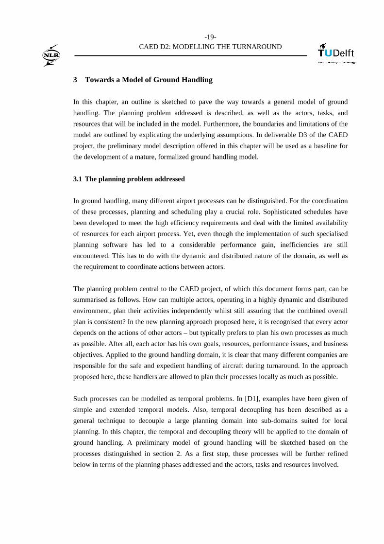
3.1.2 Actors, Tasks and Resources
At the ground handling level, a great many other actors7 are involved – as we saw in section 2
above. From these actors, the following five actors (and corresponding tasks) could be chosen
initially as the main actors to be included in the model:
7 In this chapter, the term ‘actor’ is reserved for any party, company or participant involved in ground handling.
-21-
CAED D2: MODELLING THE TURNAROUND
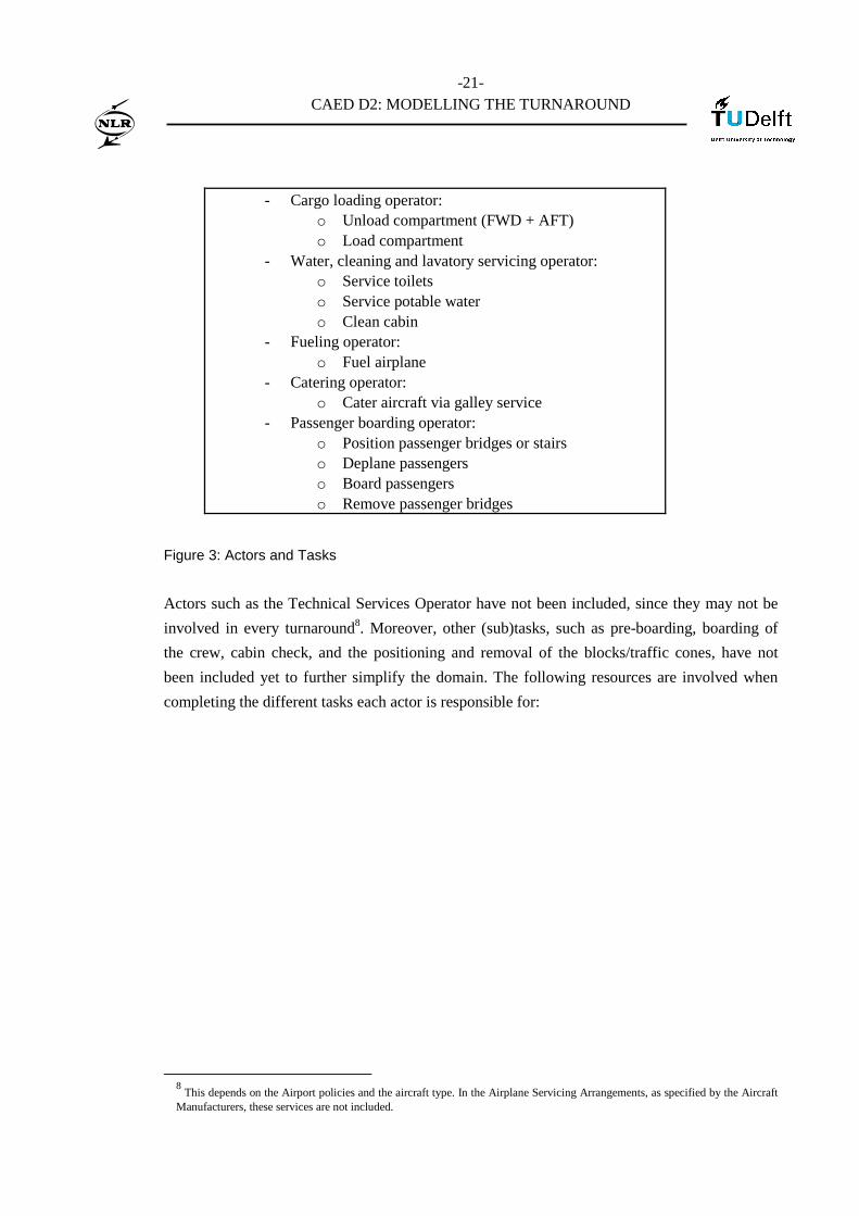
- Cargo loading operator:
o Unload compartment (FWD + AFT) o Load compartment
- Water, cleaning and lavatory servicing operator: o Service toilets o Service potable water o Clean cabin
- Fueling operator: o Fuel airplane
- Catering operator: o Cater aircraft via galley service
- Passenger boarding operator: o Position passenger bridges or stairs o Deplane passengers o Board passengers o Remove passenger bridges
Figure 3: Actors and Tasks
Actors such as the Technical Services Operator have not been included, since they may not be
involved in every turnaround8. Moreover, other (sub)tasks, such as pre-boarding, boarding of
the crew, cabin check, and the positioning and removal of the blocks/traffic cones, have not
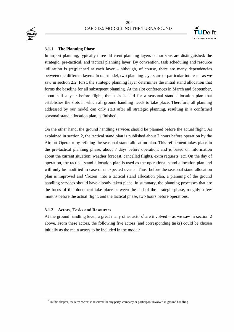
been included yet to further simplify the domain. The following resources are involved when
completing the different tasks each actor is responsible for:
8 This depends on the Airport policies and the aircraft type. In the Airplane Servicing Arrangements, as specified by the Aircraft
Manufacturers, these services are not included.

-22-
CAED D2: MODELLING THE TURNAROUND
- Cargo loading operator: o Bulk cargo loading vehicles, o Container trailers o Personnel
- Water, cleaning and lavatory servicing operator: o Water servicing vehicles o Lavatory vehicles o Cabin cleaning vehicles, o Personnel
- Fueling operator: o Fuel trucks o Personnel
- Catering operator: o Galley service trucks o Personnel
- Passenger boarding operator: o Personnel to position/remove passenger bridges
or stairs o Boarding personnel
Figure 4: Actors and Resources
Note that the actors, tasks and resources distinguished here are not final: if during further
research in WP3 a more fine-grained description of the domain is required, this will be added to
the above. We have merely outlined a baseline here for the development of an initial model.
3.2 Limitations of the Domain, Assumptions
Every good model is a simplification of reality, leaving out irrelevant detail and retaining only
that which is considered to be essential. To judge whether a model correctly represents an
operational domain, therefore, depends on the decisions made with respect to the scope and
level of simplification. What is important enough to keep in the model, and what should be left
out? This section addresses this question by describing the boundaries and limitations of the
anticipated ground handling model. Note that these limitations follow in part from the planning
phase addressed and the actors distinguished. Below, the assumptions made with respect to the
domain are listed.
Assumption 1A
The following five activities are the main activities in the ground handling domain: cargo,
cleaning, catering, fuelling, and boarding.
-23-
CAED D2: MODELLING THE TURNAROUND
Assumption 1B
Related to the five main activities, five actors are distinguished: the cargo loading operator, the
water, cleaning and lavatory servicing operator, the fuelling company, the caterer, and the
boarding company. These actors are only responsible for the tasks and resources as listed in
figures 3 and 4 above.
Assumption 1C
For the initial model, a set of about ten or fifteen aircraft types with corresponding service times
will be sufficient to test whether the model is satisfactory.
Assumption 1D
The initial model will not take into account service times that are dependent on factors other
than the aircraft type and certain airport specific requirements. For instance, airline-specific
service times9, or service times depending on specific stand allocation requirements, will be out
of scope. The model, however, should be general enough to accommodate these requirements in
a future version if necessary.
Assumption 2A
The model will address the strategic and pre-tactical planning layer: between the moment the
initial stand allocation plan is conceived (strategic) and the moment the final stand allocation
plan is fixed (tactical) 2 hours before the operation. In other words: the model will play a role in
refining10 the seasonal stand allocation plan towards the tactical stand allocation plan.
Assumption 3A
The domain covered by the model can be characterized as being dominated by largely
autonomous, self-interested actors. Cleaning companies, fuelling companies, and catering
services all have their own business interests and need to take into account business specific
constraints when planning their activities and use of resources. Therefore, the ground handling
processes are best served by putting the power in the hands of the local actors best placed to
take the decisions (CDM).
9 At Schiphol, for instance, low cost carriers may use pier H which allows for a much shorter turnaround. Also, airlines may
specify different turnaround times depending on the length of flight (KLM, for instance, distinguishes between continental and intercontinental flights). Finally, services for flights may be divided into real turnaround services, and services for flights that only arrive (loose arrivals) or depart (loose departures). 10
Refining here means that an initial seasonal stand allocation plan, developed at the strategic planning layer, will be gradually complemented with a matching services planning (phase I). In phase II of the project, this refinement will include a feedback loop to allow service providers to actually make small changes to the initial seasonal stand allocation plan. See the description of these phases in section 3.3 below.

-24-
CAED D2: MODELLING THE TURNAROUND
Assumption 3B
Related to the previous assumption, it is assumed that the ground handling tasks are best
performed if every actor is responsible for carrying out his own tasks. Thus, every actor will
benefit when the need for co-ordination with other actors during planning is minimised. Actors
will prefer to do their planning in their own manner, satisfying their own business rules and
insights as much as possible.
Assumption 4A
It is assumed that there is an important difference between the minimum service times, as
specified by aircraft manufacturers, and norm times, as specified by the airport. This difference
allows the service providers more flexibility to plan their own services, since they can shift their
tasks within this difference range.
Assumption 4B
In case of deviation in the earliest start time between minimum service times and norm times, it
is assumed that a service can never start earlier than the norm time specified by the airport. In
other words, when determining the earliest possible start time for a service, the norm time
specified by the airport takes precedence.
Assumption 4C
In case of deviation in the duration between minimum service times and norm times, it is
assumed that the minimum time required to provide the service is the time specified by the
aircraft manufacturer. In other words, when determining the minimum duration of a service, the
minimum service time specified by the aircraft manufacturer takes precedence.
Assumption 5A
The model is intended to be used primarily by the service providers. It should assist them in
making their own local planning, taking the constraints resulting from the seasonal stand
allocation plan and other service providers into account.
Assumption 6A
It is assumed that, if the local service providers have more flexibility in planning their own
resources and activities, this will lead to a better tactical stand allocation plan. After all, the
interests of the service providers will be better covered, leading to a more efficient local
planning.

-25-
CAED D2: MODELLING THE TURNAROUND
Assumption 6B
Related to the previous assumption, it is further assumed that if local service providers are given
more flexibility in planning, or are even rendered direct influence on the refinement of the
seasonal stand allocation plan, this will also lead to a more robust local planning. In other
words, a tactical stand allocation plan based on flexible ground handling planning is assumed to
improve the ability to react to unforeseen disturbances in the tactical/operational phase.
3.3 Goals of the Model per Project Phase
In the previous two subsections, the outlines of a ground handling model have been sketched.
The actors, tasks and resources involved have been detailed, and the assumptions made with
respect to the model have been stated. In this section, the high-level goals that the model should
meet will be listed.
These goals can be divided into two groups. The division corresponds to the two phases
foreseen in the CAED project. Phase I, to be implemented in the first year of the project,
addresses the development and possible automation of the extreme decoupling process from a
mere stand allocation plan to a stand & services allocation plan. Phase II, to be performed in an
additional two years of research, will build on the developed model, methodology and possible
prototype in order to implement a loop, allowing ground handlers to actually change the stand
allocation plan (via small-scale change proposals). This last phase is not addressed in this
document, since the scope is restricted here to the first year of research. Section 3.4 below gives
some more detail on both project phases.
Below, two sets of high-level goals are given. Goals 1 and 2 relate to phase I of the project.
Goal 3 is only relevant to phase II. In WP3, the first two goals will be further elaborated and
refined into a list of specific requirements for the ground handling model.
Goal 1
As can be concluded from assumptions 3A and 3B, the model’s primary goal should be to
minimize the required co-ordination in planning between actors as much as possible – whilst
preventing that these plans are in conflict with one another.
Goal 2
Apart from preventing conflicts to occur between individual plans of service providers, the
model should also prevent its user from making plans that are in conflict with the seasonal stand
allocation plan. Thus, the model should be able to automatically constrain the search space of
the local planner (the service provider) based on the stand allocation plan (the slots in which the
-26-
CAED D2: MODELLING THE TURNAROUND
services should be performed), and aircraft and airport specific constraints (determining roughly
the lower and upper bounds for each service to be performed).
Goal 3
The model should, in phase II, allow its users also to affect the seasonal stand allocation plan.
Thus, service providers will be allowed to have an influence in the process of refining the
seasonal stand allocation plan towards its mature state in the tactical stand allocation plan.
3.4 High-level Description of the Model
In this subsection, a first sketch will be given of a ground handling model that, within the
limitations of section 3.1 and based on the assumptions of section 3.2, could meet the goals of
section 3.3. The high-level description detailed here will be based on the two project phases
distinguished in the previous section.
In phase I, the model could be used to automatically generate local search spaces, constrained
by the seasonal stand allocation plan and the plans of other service providers. To achieve this, a
Simple Temporal Network (STN) model should be constructed based on different sets of inputs:
the seasonal stand allocation plan, aircraft type specific service times, airport specific
constraints, etc. Section 4 below gives an example of such a STN representation of the domain.
Next, the decoupling algorithm will be used to decouple the network into local networks - as
discussed in [D1]. To this end, first the seasonal stand allocation plan constraints and
corresponding airport-specific ‘norm times for the gate services’ are decoupled, taking
advantage of the latitude that typically exists between these norm times and the minimal service
times as specified by aircraft manufacturers. When properly decoupled, service providers (SPs)
can do their own, local planning – without requiring any further co-ordination with other
parties.
To establish their own local plan, service providers can either use their own planning methods
and tools11, or take advantage of the set of search algorithms for extended STNs as proposed in
this research project (see chapters 4 and 5 of [D1]). Note that, given the latitude between norm
times and minimal service times, the SPs will have quite a lot of flexibility in accommodating
their local plans to their local constraints and local business models. Once established, the local
plans are guaranteed to be conflict-free when merged again with other local plans due to the
Mergeable Solutions Property of the decoupling algorithm. The result, then, is a tactical stand
allocation plan that incorporates all local services planning. This result could be tested in the
11
These methods and tools should however be able to work with the STN representation that results from applying the decoupling algorithm.
-27-
CAED D2: MODELLING THE TURNAROUND
tactical/operational phase, by demonstrating that the resulting tactical plan can deal better with
unforeseen circumstances – for example during winter conditions.
In phase II, the implementation of a planning loop is foreseen, allowing for multiple iterations if
necessary. This loop enables local planners to have an influence on the refinement of the
seasonal stand allocation plan: a new operational feature. Thus, large inefficiencies in the local
planning of service providers can be prevented by allowing slight modifications in the stand
allocation plan. For instance, when a fuelling company has to service ten aircraft at the same
time, requiring a large peak in personnel and fuelling vehicles, the company may propose to
slightly change the stand allocation plan to better spread out the fuelling activity in time.
Contrary to phase I, which only automates and aids the local planners in establishing their own
local plans, phase II therefore actually allows local planners to influence and even modify the
pre-tactical stand allocation plan.
-28-
CAED D2: MODELLING THE TURNAROUND
4 A Ground Handling Example
This chapter describes how the preliminary ground handling model of the previous section can
be applied in practice. To do so, first an operational example is given, which serves as a running
example for the remainder of the chapter. Next, it is demonstrated how a STN model can be
constructed based on this example – and other relevant domain knowledge (section 4.1). In the
following, the decoupling of this model in local sub-models is shown (section 4.2). Finally, a set
of solutions for these decoupled sub-models is presented (section 4.3).
4.1 Constructing a Model of the Domain
In this section, an simple example is used to demonstrate how a Simple Temporal Network
(STN) could be constructed from the ground handling domain. In a step-by-step fashion, the
example is elaborated and a set of variables, resources, and temporal constraints is distilled from
the domain. Next, a network is built in which the nodes represent the variables and the edges
between the nodes the temporal constraints of the domain. The resulting STN is a formal
representation of the example domain.
Imagine the following, simplified partition of a seasonal stand allocation plan:
• Aircraft 1, KL310, type B737-300, Gate A17, in-block 12:00, off-block 13:15.
• Aircraft 2, LH200, type MD11, Gate A23, in-block 12:05, off-block 14:10.
Furthermore, imagine that we have technical information about the required turnaround time
and corresponding service times for each aircraft type. This information can be split up into two
groups, as explained above. In the first group, the airport-defined turnaround and ground
handling services are stated. These are the so-called norm times, including – at most airports
and for most airlines – a safety margin to absorb any small servicing delays that may occur in
the operational phase. In the second group, the minimum service times are stated as specified by
the aircraft manufacturers. For example, for the first aircraft, a Boeing 737, the following norm
times could be defined12 by the airport for three example services:
• Turnaround: 55 min. duration
• Fuelling: 25 min. duration (with and additional margin of 12 min), starting 8
min after in-block at the earliest
12
These norm times are example norm times, but can in fact be regarded as typical norm times for an airport.
-29-
CAED D2: MODELLING THE TURNAROUND
• Cargo: 46 min. duration, starting 4 min after in-block at the earliest
• Boarding: 15 min. duration (with an additional margin of 4 min), starting 32
min after in-block at the earliest
Conversely, the Airplane Terminal Operations (Airplane Servicing Arrangement) for a B737-
300 states [Boeing; see Appendix B for details]:
• Turnaround: 38 min. duration
• Fuelling: 10 min. duration
• Cargo: 30 min. duration
• Boarding: 5 min. duration
The same can be done for the McDonnell Douglas in our example. The norm times as defined
by the airport:
• Turnaround: 120 min. duration
• Fuelling: 59 min. duration, starting 11 min after in-block at the earliest
• Cargo: 25 (unload) + 45 (load) = 70 min. duration, starting 3 min after in-
block at the earliest
• Boarding: 36 min. duration, starting 80 min after in-block at the earliest
and the airplane servicing arrangement for a MD11 [Boeing; see Appendix B]:
• Turnaround: 51.4 min. duration
• Fuelling: 16.6 min. duration
• Cargo (2 subtasks): 18 + 18 = 36 min. duration
• Boarding: 16.2 min. duration
Based on the seasonal stand allocation plan and the information above, we can now construct a
large STP by following a simple procedure:
-30-
CAED D2: MODELLING THE TURNAROUND
Figure 5: Pseudo-code for constructing a STP-model given a seasonal stand allocation plan
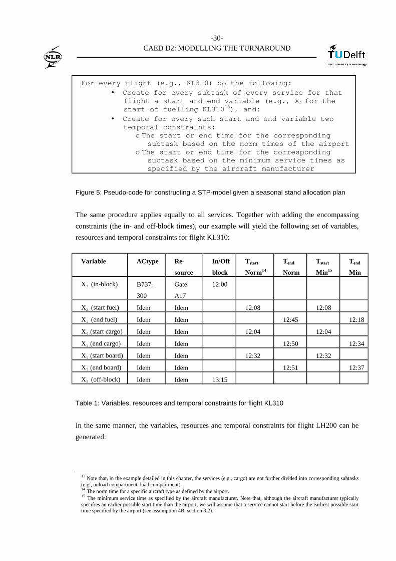
The same procedure applies equally to all services. Together with adding the encompassing
constraints (the in- and off-block times), our example will yield the following set of variables,
resources and temporal constraints for flight KL310:
Variable ACtype Re-
source
In/Off
block
Tstart
Norm14
Tend
Norm
Tstart
Min15
Tend
Min
X1 (in-block) B737-
300
Gate
A17
12:00
X2 (start fuel) Idem Idem 12:08 12:08
X3 (end fuel) Idem Idem 12:45 12:18
X4 (start cargo) Idem Idem 12:04 12:04
X5 (end cargo) Idem Idem 12:50 12:34
X6 (start board) Idem Idem 12:32 12:32
X7 (end board) Idem Idem 12:51 12:37
X8 (off-block) Idem Idem 13:15
Table 1: Variables, resources and temporal constraints for flight KL310
In the same manner, the variables, resources and temporal constraints for flight LH200 can be
generated:
13 Note that, in the example detailed in this chapter, the services (e.g., cargo) are not further divided into corresponding subtasks (e.g., unload compartment, load compartment). 14 The norm time for a specific aircraft type as defined by the airport. 15 The minimum service time as specified by the aircraft manufacturer. Note that, although the aircraft manufacturer typically specifies an earlier possible start time than the airport, we will assume that a service cannot start before the earliest possible start time specified by the airport (see assumption 4B, section 3.2).
For every flight (e.g., KL310) do the following: • Create for every subtask of every service for that
flight a start and end variable (e.g., X2 for the start of fuelling KL31013), and:
• Create for every such start and end variable two temporal constraints:
o The start or end time for the corresponding subtask based on the norm times of the airport
o The start or end time for the corresponding subtask based on the minimum service times as specified by the aircraft manufacturer

-31-
CAED D2: MODELLING THE TURNAROUND
Variable ACtype Re-
source
In/Off
block
Tstart
Norm
Tend
Norm
Tstart
Min
Tend
Min
Y1 (in-block) MD11 Gate
A23
12:05
Y2 (start fuel) Idem Idem 12:16 12:16
Y3 (end fuel) Idem Idem 13:15 12:33
Y4 (start cargo) Idem Idem 12:08 12:08
Y5 (end cargo) Idem Idem 13:18 12:44
Y6 (start board) Idem Idem 13:25 13:25
Y7 (end board) Idem Idem 14:01 13:41
Y8 (off-block) Idem Idem 14:10
Table 2: Variables, resources and temporal constraints for flight LH200
These tables can be constructed as follows. The first flight (KL310), for instance, is a Boeing
737-300. In the corresponding airplane servicing arrangement, it is stated that fuelling can begin
8 minutes after in-block at the earliest [Boeing, B737]. Moreover, since fuelling will take a
minimum of 10 minutes, the earliest completion time of the task is, according to this document,
18 minutes after in-block. Given the in-block time of 12:00 noon, this yields a Tstart Min of
12:08 and Tend Min of 12:18. The same can be done for the norm times of that aircraft, and for
all other flights. For example, the Tend Norm of the boarding of flight LH200 can be calculated
by adding the duration (36 minutes) to the earliest starting time from in-block (80 minutes) to
the in-block time (5 minutes after 12:00 noon). Note the margin between the minimum end time
and the end time as specified by the airport (e.g., 12:18 and 12:45 for fuelling of flight KL310).
At this point, a remark should be made. When defining minimum end times of services, one
might think that it is always good to deliver services as quickly as possible. This is not always
the case, however. When servicing has been completed and all passengers are on board half an
hour before the planned off-block time, passengers tend to get agitated. More concretely: extra
constraints should hold for at least two services, de-boarding and boarding. After all, de-
boarding should take place as soon as possible after in-block, and boarding not too long before
off-block. In our example, only boarding plays a role. We will assume here that passengers
should not wait longer than 15 minutes after boarding before going off-block.
Based on our example, Tables 1 and 2 above now defines eighteen tasks, and a variety of
temporal constraints. These temporal constraints specify when the tasks should be executed.
The norm times could now be regarded as hard constraints, marking the earliest start and latest
end time of a task. The minimum service times, in turn, could indicate the minimum duration of

-32-
CAED D2: MODELLING THE TURNAROUND
a task – and thus, indirectly, the margin which the service provider has for planning his service
in the hard-constrained slot. Some other temporal constraints should be taken into account,
however.
Apart from so-called time bound constraints, which specify at what time, or before or after what
time a task should be executed, another type of temporal constraints applies to the domain:
precedence constraints. Whereas time bound constraints determine the time at which tasks
should be executed, precedence constraints determine the order. In the tables above, only time
bound constraints are defined, constraining the time at which tasks should start or end.
However, many precedence constraints between the tasks exist as well, constraining the way
they should be ordered in time. Such precedence constraints are, for example:
• ‘In-block’ occurs before all other services
• ‘De-boarding’ must take place before catering, cleaning, boarding
• ‘Position passenger bridge’ must take place before all other services
• ‘Cabin cleaning’ must take place after ‘De-boarding’ and before ‘Boarding’
• For many aircraft types, airport, airlines, it holds that ‘Fuelling’ should not take place
during ‘De-boarding’ or ‘Boarding’, unless the fire brigade is present
• ‘Off-block’ occurs after all other services
In our example, the start and end time of the fuelling task may depend on whether de-boarding
is completed, or boarding has commenced. This in turn depends on airport regulations, airline
policies, or even aircraft-specific rules16. The dependencies relevant to our example are:
• ‘In-block’ occurs before ‘Fuelling’, ‘Cargo’, ‘Boarding’
• ‘Fuelling’, ‘Cargo’, ‘Boarding’ occur before ‘Off-block’
• ‘Fuelling’ occurs before ‘Boarding’
At this stage, we are ready to construct a Simple Temporal Network (STN) based on the
domain. For the “fuelling” and “boarding” tasks of Flight 1, for instance, we could build the
following STN consisting of 7 nodes and 9 edges:
16 Note that most airplane servicing arrangements, specified by the aircraft manufacturer, do in fact rarely prohibit the simultaneous execution of fuelling and (de)boarding.

-33-
CAED D2: MODELLING THE TURNAROUND
Figure 6: STN for services “fuelling” and “boarding” of Flight 1
In this Figure, six variables have been selected from Table 1 above: X1, X2, X3, X4, X5, and X8.
Note that the precedence constraints determine the order in which the variables are placed in the
STN. Additionally, the temporal reference point X0 is added. The reader is referred to [D1],
chapter 2, for further information on STNs. For the reference point X0, the time 12:00 noon is
chosen. Since flight 1 goes in-block at exactly 12:00 noon, the minimum and maximum time
allowed between variable X0 and X1 is simply [0,0]17 – as indicated next to the edge. The
following task, X2, is the fuelling activity itself. The temporal constraint [8,∞] between X1 and
X2 denotes that fuelling can start 8 minutes after in-block at the earliest, and that there is no
direct upper bound known given our information18.
The same can be done for the other constraints. For instance, fuelling itself can last anywhere
between 10 minutes (airplane servicing arrangement) and 25 minutes + 12 minutes margin = 37
minutes (norm time). Thus, the transition between ‘fuelling’ X2 and ‘done fuelling’ X3 is
constrained by [10,37]. Furthermore, the transition between ‘in-block’ X1 and ‘done fuelling’ X3
should be anywhere between the earliest end time Tend Min and the latest end time Tend Norm:
[18,45]. The next constraint is [32,∞] , indicating that ‘boarding’ X4 cannot start earlier than 32
17 This indicates that the flight must be in-block at exactly 12:00 a.m. 18
Note that, if required, one could infer an upperbound. Since fuelling will last until 12:18 at the earliest (Tend Min), and 12:45 at the latest (Tend Norm), as stated in table 1, and since the minimum time for fuelling is 10 minutes, as identified in the B737-300 airplane servicing arrangement, fuelling can start no later than 12:35 if the activity should be completed at 12:45. Therefore, the upper bound for the start of X2 could be 35. It is much easier, however, to use precisely the information we have (not stating an upperbound) and instead add the temporal constraint [18,45] between X0 and X2. The upperbound 45 between X0 and X2 will then also constrain the transition X0 and X1.
12 o’clock
x0
x1 x2 X3 [8,∞] [10,37]
[0,0]
[75,75]
in-block boarding
12:00 noon
X8
off-block
[0,∞]
fuelling
[18,45]
13:15 pm
X5
[0,15]
done
x4
done
[5,18]
[32,∞]

-34-
CAED D2: MODELLING THE TURNAROUND
minutes after in-block X1. Boarding itself may last minimally 5 minutes (Tend Min) and
maximally 18 minutes (Tend Norm), yielding [5,18]. After ‘boarding’, moreover, there should
be time for other services not included in our example. This is why node X5 is added: to indicate
that ‘boarding’ is done. Since we have said that passengers should not have to wait longer than
15 minutes before off-block, the time between X5 and X8 is constrained by [0,15]. Also, since the
off-block should take place at exactly 13:15 p.m., there is a time constraint of [75,75] between
in-block (X5) and off-block (X8). Node X8, finally, indicates the end of the turnaround process.
In a next step, we could add the cargo service to the STN above. This would yield the following
model of Flight 1:
Figure 7: STN for services “fuelling”, “boarding” and “cargo” of Flight 1
Note that, in Figure 7, variables X6 and X7 have been added for the ‘cargo’ and ‘cargo done’
activities, respectively. From the figure, one can conclude that unloading and loading the cargo
can start 4 minutes after in-block at the earliest, whereas the activity itself requires at least 30
and at most 46 minutes.
X6
cargo
[4,∞] X7
[30,46] [0,∞]
cargo done
12 o’clock
X0
X1 X2 X3 [8,∞] [10,37]
[0,0]
[75,75]
in-block boarding
12:00 noon
X8
off-block
[0,∞]
fuelling
[18,45]
13:15 pm
X5
[0,15]
done
X4
done
[5,18]
[32,∞]
-35-
CAED D2: MODELLING THE TURNAROUND
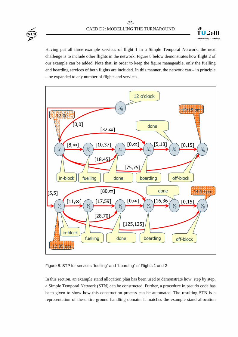
Having put all three example services of flight 1 in a Simple Temporal Network, the next
challenge is to include other flights in the network. Figure 8 below demonstrates how flight 2 of
our example can be added. Note that, in order to keep the figure manageable, only the fuelling
and boarding services of both flights are included. In this manner, the network can – in principle
– be expanded to any number of flights and services.
Figure 8: STP for services “fuelling” and “boarding” of Flights 1 and 2
In this section, an example stand allocation plan has been used to demonstrate how, step by step,
a Simple Temporal Network (STN) can be constructed. Further, a procedure in pseudo code has
been given to show how this construction process can be automated. The resulting STN is a
representation of the entire ground handling domain. It matches the example stand allocation
12 o’clock
X0
X1 X2 X3 [8,∞] [10,37]
[0,0]
[75,75]
in-block boarding
X8
off-block
[0,∞]
fuelling
[18,45]
X5
[0,15]
done
X4
done
[5,18]
[32,∞]
Y1 Y2 Y3 [11,∞] [17,59]
[125,125]
in-block boarding
Y8
off-block
[0,∞]
fuelling
[28,70]
Y5
[0,15]
done
Y4
done
[16,36]
[80,∞] [5,5]
12:05 pm
12:00
13:15 pm
14:10 pm

-36-
CAED D2: MODELLING THE TURNAROUND
plan and all constraints that can be deduced from it. In a next step, this high-level ground
handling STN should be decoupled and divided amongst the various service providers. The next
section addresses this issue.
4.2 Decoupling the Domain Model
In this section, the example STN built up in the previous section will be used to demonstrate
Hunsberger’s decoupling algorithm. It is assumed here that this algorithm is implemented and
can be applied to STNs representing our domain. For the theory behind decoupling the reader is
referred to chapter 5 of [D1]. This section merely shows how Hunsberger’s algorithm can be
applied to the domain – and what the resulting partition of local planning domains could look
like.
As a first step, Figure 9 below shows how the above STN, representing (part of) the example
domain, can be decoupled in two parts. The first part (shaded) matches the temporal network for
the fuelling company, the second (spotted) the network for the boarding company.
-37-
CAED D2: MODELLING THE TURNAROUND
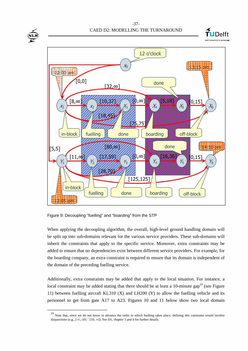
Figure 9: Decoupling “fuelling” and “boarding” from the STP
When applying the decoupling algorithm, the overall, high-level ground handling domain will
be split up into sub-domains relevant for the various service providers. These sub-domains will
inherit the constraints that apply to the specific service. Moreover, extra constraints may be
added to ensure that no dependencies exist between different service providers. For example, for
the boarding company, an extra constraint is required to ensure that its domain is independent of
the domain of the preceding fuelling service.
Additionally, extra constraints may be added that apply to the local situation. For instance, a
local constraint may be added stating that there should be at least a 10-minute gap19 (see Figure
11) between fuelling aircraft KL310 (X) and LH200 (Y) to allow the fuelling vehicle and its
personnel to get from gate A17 to A23. Figures 10 and 11 below show two local domain
19
Note that, since we do not know in advance the order in which fuelling takes place, defining this constraint would involve disjunctions (e.g., [-∞,-10] ∪[10, ∞]). See D1, chapter 3 and 4 for further details.
12 o’clock
x0
x1 x2 X3
[8,∞] [10,37]
[0,0]
[75,75]
in-block boarding
X8
off-block
[0,∞]
fuelling
[18,45]
X5
[0,15]
done
X4
done
[5,18]
[32,∞]
Y1 Y2 Y3 [11,∞] [17,59]
[125,125]
in-block boarding
Y8
off-block
[0,∞]
fuelling
[28,70]
Y5
[0,15]
done
Y4
done
[16,36]
[80,∞] [5,5]
12:05 pm
12:00 am
13:15 pm
14:10 pm

-38-
CAED D2: MODELLING THE TURNAROUND
representations that may result from applying the decoupling algorithm to the example domain
above.
Figure 10: The decoupled “fuelling” service
Note that X0 , the reference point, is part of both figures 10 and 11, whereas the in-block
variables X1 and Y1 are not. As a result, constraints are added between X0 and X2 / Y2 in figure 10
and between X0 and X4 / Y4 in figure 11 to reflect the previous constraints between in-block and
the start and end of the core activity. For example, in figure 10 the set of constraints [5,5] and
[11, ∞] between variables X0, Y1 and Y2 is translated into the constraint [16, ∞] between X0 and Y2
to reflect that fuelling of aircraft Y should start at least 5 + 11 = 16 minutes after 12:00 noon.
Similarly, the set of constraints [5,5] and [28,70] is translated into the constraint [33,75].
X2 X3
[8,∞]
[10,37]
[18,45]
end fuelling
Y2 Y3 [17,59]
start fuelling
[33,75]
end fuelling
[16,∞]
12 o’clock
x0 start fuelling X
-39-
CAED D2: MODELLING THE TURNAROUND
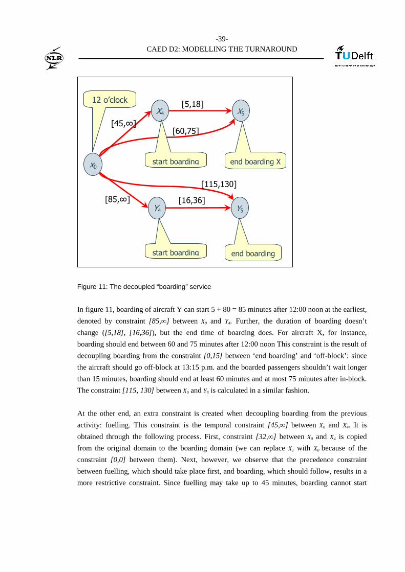
Figure 11: The decoupled “boarding” service
In figure 11, boarding of aircraft Y can start 5 + 80 = 85 minutes after 12:00 noon at the earliest,
denoted by constraint [85,∞] between X0 and Y4. Further, the duration of boarding doesn’t
change ([5,18], [16,36]), but the end time of boarding does. For aircraft X, for instance,
boarding should end between 60 and 75 minutes after 12:00 noon This constraint is the result of
decoupling boarding from the constraint [0,15] between ‘end boarding’ and ‘off-block’: since
the aircraft should go off-block at 13:15 p.m. and the boarded passengers shouldn’t wait longer
than 15 minutes, boarding should end at least 60 minutes and at most 75 minutes after in-block.
The constraint [115, 130] between X0 and Y5 is calculated in a similar fashion.
At the other end, an extra constraint is created when decoupling boarding from the previous
activity: fuelling. This constraint is the temporal constraint [45,∞] between X0 and X4. It is
obtained through the following process. First, constraint [32,∞] between X0 and X4 is copied
from the original domain to the boarding domain (we can replace X1 with X0 because of the
constraint [0,0] between them). Next, however, we observe that the precedence constraint
between fuelling, which should take place first, and boarding, which should follow, results in a
more restrictive constraint. Since fuelling may take up to 45 minutes, boarding cannot start
X4 X5
[45,∞]
[5,18]
[60,75]
end boarding X
Y4 Y5 [16,36]
start boarding
[115,130]
end boarding
[85,∞]
12 o’clock
x0 start boarding

-40-
CAED D2: MODELLING THE TURNAROUND
before 12:45 p.m. if we are to ensure that there is no interference between both activities. Thus,
the more restrictive [45,∞] replaces [32,∞] as the temporal constraint between X0 and X4.20
This section gave an idea of how the decoupling algorithm could be applied to our example, and
what the resulting sub-networks might look like. All we have done so far, however, is related to
constructing a model of reality. We built a representation of the overall problem domain
(section 4.1) and decoupled this representation into small sub-models (section 4.2). We have not
solved anything yet, though.
4.3 Solving the Decoupled Planning Problems
In this section, we will look at example solutions to the local planning problems depicted in
figures 10 and 11. The process of arriving at this solution, whether through Floyd-Warshall’s
algorithm, the ∆STP algorithm, or through Local Search, is beyond the scope of this document.
The reader is referred to chapters 2 to 5 of [D1] for a description of algorithms that could do the
job. In deliverable D3, an extensive description will be given of how the algorithms of [D1] can
be utilised to solve the operational problem sketched in this document. In this section, we
merely offer example solutions that satisfy the temporal constraints laid down in figures 10 and
11.
For figure 10, it is not difficult to find a solution. Since for aircraft X fuelling can start at t=8,
whilst aircraft Y should wait until t=16, it seems natural to first fuel X, then Y. If we further
assume that the fuelling company wants to minimize the time required for fuelling (10 minutes
for X, 17 for Y), we could get the following solution:
20
Note that other, less restrictive decouplings are possible here.
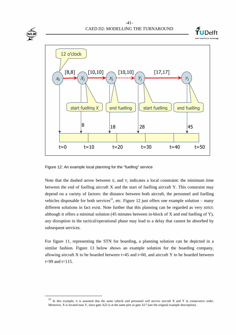
-41-
CAED D2: MODELLING THE TURNAROUND
Figure 12: An example local planning for the “fuelling” service
Note that the dashed arrow between X3 and Y2 indicates a local constraint: the minimum time
between the end of fuelling aircraft X and the start of fuelling aircraft Y. This constraint may
depend on a variety of factors: the distance between both aircraft, the personnel and fuelling
vehicles disposable for both services21, etc. Figure 12 just offers one example solution – many
different solutions in fact exist. Note further that this planning can be regarded as very strict:
although it offers a minimal solution (45 minutes between in-block of X and end fuelling of Y),
any disruption in the tactical/operational phase may lead to a delay that cannot be absorbed by
subsequent services.
For figure 11, representing the STN for boarding, a planning solution can be depicted in a
similar fashion. Figure 13 below shows an example solution for the boarding company,
allowing aircraft X to be boarded between t=45 and t=60, and aircraft Y to be boarded between
t=99 and t=115.
21
In this example, it is assumed that the same vehicle and personnel will service aircraft X and Y in consecutive order. Moreover, X is located near Y, since gate A23 is at the same pier as gate A17 (see the original example description).
X2 X3
[8,8] [10,10]
Y2 Y3
start fuelling
[17,17] [10,10]
12 o’clock
x0
t=0 t=10 t=20 t=30 t=40 t=50
end fuelling end fuelling start fuelling X
8 18 28 45

-42-
CAED D2: MODELLING THE TURNAROUND
Figure 13: An example local planning for the “boarding” service
In figure 13, the dashed arrow indicates a minimum gap of 39 minutes separating the boarding
of X and Y. This gap, which might be used by the boarding company to board another aircraft
in between (depending on local constraints), is the result of two constraints: first, Y cannot start
boarding before t=85 (see Figure 11), since this is in-block time (12:05 p.m.) plus the norm time
(80 min.) for boarding for a MD11. Second, however, since the aircraft should take off at 14:10
p.m. (t=130) but the boarded passengers shouldn’t have to wait longer than 15 minutes before
take-off, boarding should finish not earlier than t=115. In figure 13, a solution is chosen which
maximizes the time between the end of boarding and take-off of Y (e.g., to maximally absorb
any possible delay). Additionally, the gap between the end of boarding of X and Y is
maximized – for instance to allow another aircraft to be boarded in between. Finally, boarding
of X is started as early as possible to be able to absorb any possible delays that might occur
before or during boarding22.
This concludes the discussion of our ground handling example. In the previous sections, a high-
level STN has been constructed to represent the example domain, and a decoupling of this STN
22
Note that, for this reason, the boarding is planned to take place between t=45 and t=60: 15 minutes instead of the minimum of 5 minutes for a B737-300.
X2 X3
[45,45]
[15,15]
Y2 Y3
[16,16]
[39,39]
12 o’clock
x0
t=0 t=25 t=50 t=75 t=100 t=125
end boarding start boarding
60 45 99 115
start boarding end boarding

-43-
CAED D2: MODELLING THE TURNAROUND
into two local STNs has been detailed. In this section, two example solutions have been
presented to demonstrate the result of local planning given the decoupled STNs.
-44-
CAED D2: MODELLING THE TURNAROUND
5 Conclusions and Future Work
In this document, the operational context for the Co-ordinated Airport through Extreme
Decoupling (CAED) has been described. The first chapter sketched the CDM and TAM context
of the project, as well as the overall turnaround process – the CAED application domain. In the
second chapter, this turnaround process was further elaborated by describing the various ground
handling processes to be performed during turnaround. Moreover, the relation between ground
handling and stand planning has been addressed. Additionally, the importance of ground
handling for punctuality and efficiency in airport operations has been emphasised as our starting
point for further research.
In the third chapter, an outline has been presented for a general model of ground handling. This
outline will be developed further in deliverable D3 of the project, describing a mature ground
handling model. In chapter 3, the planning problem addressed has been described, as well as the
actors, tasks, and resources that will be included in the model. Furthermore, the boundaries and
limitations of the model have been drawn by explicating the underlying assumptions.
In the fourth chapter, finally, the model described in chapter 3 is given more contents. By means
of an operational example, this chapter illustrated how the ground handling model can be
applied in practice. The example was translated step by step into a Simple Temporal Network
(STN) representation. This STN, in turn, was decoupled into local sub-networks – matching the
perspective of the local ground handlers. Finally, a set of solutions to these decoupled networks
has been presented.
This concludes the description of the operational domain of the CAED project. The turnaround
process has been described in detail, as well as its relation to other airport processes.
Furthermore, a direction has been sketched for further modelling of the turnaround process. A
general methodology has been outlined to support the integration of local planning functions
into an encompassing, total airport planning by means of extreme decoupling. Together with
[D1], describing the theory behind decoupling and temporal networks, this document aims to
pave the way for deliverable D3 of the project.
In this deliverable, the extreme decoupling methodology sketched here will be further
elaborated. Deliverable D3 will provide a more mature turnaround model (representation), a
detailed description of the decoupling process in steps (a methodology), and set of local solving
strategies (algorithmic implementation). By means of this model, methodology and solving
strategies, local service providers will be able to decouple their overall planning constraints

-45-
CAED D2: MODELLING THE TURNAROUND
from the stand allocation plan, solve their planning problems locally, and merge their local
plans to a guaranteed conflict-free stand and services plan. Moreover, if time permits, a simple
prototype will be developed and described in D3. This prototype will be used to test the new
planning concept against a small-scale, yet realistic scenario, demonstrating its benefits and
possible drawbacks.

-46-
CAED D2: MODELLING THE TURNAROUND
6 References
References are divided into document references and online references.
6.1 Document References
AAM ConOps Eurocontrol, Eurocontrol ATM Operation Concept - Concept of Operations
for 2011, volume 2, Ed. 1.0, May 2005
D1 Eurocontrol, CAED Deliverable D1, Literature Survey on Temporal
Decoupling, March 2007
IATA IATA, Airport Handling Manual, International Air Transport Association,
24th edition, 2004.
LEO Pim van Leeuwen, Requirements and Design Document for LEONARDO’s
collaborative decision making multi-agent system CDMMA, Technical
Report NLR-TR-2003-653, National Aerospace Laboratory NLR, January
2004.
Wu et al. Cheng-Lung Wu, Robert E. Caves, 2000, Aircraft operational cost and
turnaround efficiency at airports, Journal of Air Transport Management,
vol 6, issue 4, pp 201-208.
Wu et al. Cheng-Lung Wu, Robert E. Caves, 2004a, Modelling and Simulation of
Aircraft Turnaround operations at Airports, Transportation Planning and
Technology, vol 27, issue 1, pp 25-46.
Wu et al. Cheng-Lung Wu, Robert E. Caves, 2004b, Modelling and Optimization of
Aircraft Turnaround Time at Airports, Transportation Planning and
Technology, vol 27, issue 1, pp 47-66.
-47-
CAED D2: MODELLING THE TURNAROUND
6.2 Online references
AAM Eurocontrol, Airport Airside Management project, Airport Operations
Architecture Description Document. In the course of this project a number
of Use Cases and Operational Scenarios have been developed to describe
operations around stand allocation. Also, actors lists including e.g. the
Stand Planner have been developed. Downloadable at:
http://www.eurocontrol.int/oca/gallery/content/public/docs/
OATA-P2-D4.2.7-04-52%20Airport%20Operations%20ADD.pdf
See page 13 for the ‘Stand Planner’ actor; page 18 for the ‘Establish Stand
Allocation Plan’, page 20 for the ‘Update Stand Allocation Plan’.
Boeing Boeing website, Airplane Servicing Arrangements, downloadable at:
http://www.boeing.com/commercial/airports/acaps/737.pdf (Boeing 737)
http://www.boeing.com/commercial/airports/acaps/md11.pdf (MD11)
CDM Handbook Eurocontrol, Airport CDM Guide, February 2003, downloadable at:
http://www.eurocontrol.int/airports/gallery/content/public/pdf/cdm_guide.pdf
G2G Eurocontrol, Gate to Gate Programme (5th Framework, started in 2002). For
more project information:
http://www.eurocontrol.int/eec/public/standard_page/SSP_gate_to_gate.html
TAM Eurocontrol, Total Airport Management preliminary study, final report,
November 2001, downloadable at:
http://www.eurocontrol.int/care-innov/gallery/content/public/docs/
studies2001/tam_finalreportr1.1.pdf

-48-
CAED D2: MODELLING THE TURNAROUND
Appendix A Airplane Servicing Arrangements for the B737-300 and MD11
Source: [Boeing]. On the Boeing website, the airplane characteristics for a range of aircraft can
be found. Section 5 of these documents yields the so-called ‘Airplane Servicing Arrangements’.
Figure 14: Airplane Servicing Arrangement for the B737-300.
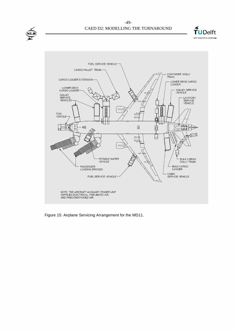
-49-
CAED D2: MODELLING THE TURNAROUND
Figure 15: Airplane Servicing Arrangement for the MD11.
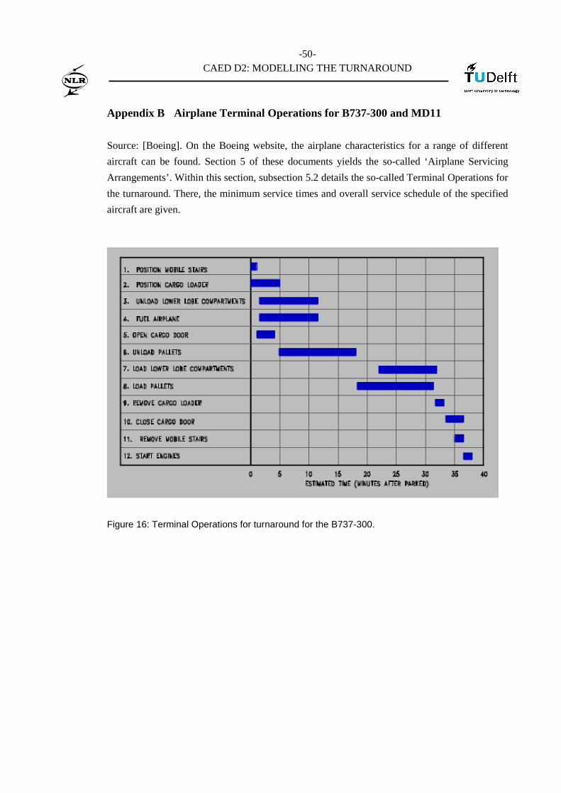
-50-
CAED D2: MODELLING THE TURNAROUND
Appendix B Airplane Terminal Operations for B737-300 and MD11
Source: [Boeing]. On the Boeing website, the airplane characteristics for a range of different
aircraft can be found. Section 5 of these documents yields the so-called ‘Airplane Servicing
Arrangements’. Within this section, subsection 5.2 details the so-called Terminal Operations for
the turnaround. There, the minimum service times and overall service schedule of the specified
aircraft are given.
Figure 16: Terminal Operations for turnaround for the B737-300.
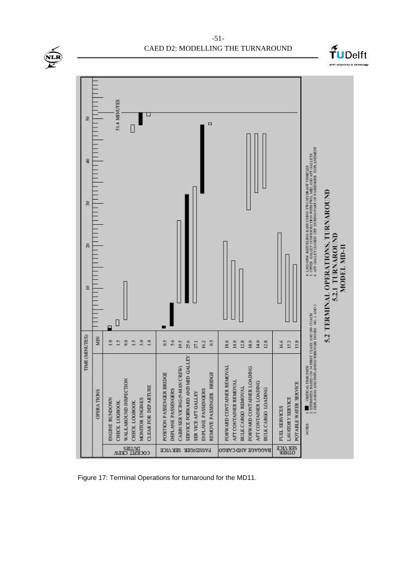
-51-
CAED D2: MODELLING THE TURNAROUND
Figure 17: Terminal Operations for turnaround for the MD11.


![Tier 3 Submission March 5, 2015 College of …content-calpoly-edu.s3.amazonaws.com/caed/1/images/Read...Freddy Svedskin] Student work designed in a studio, fabricated in the CAED Support](https://img.pdfslide.us/doc/110x75/5f62e4fb9baf29552a625362/tier-3-submission-march-5-2015-college-of-content-calpoly-edus3-freddy-svedskin.jpg)