Embed Size (px)
Citation preview
.4--
Report No. cG-D-12-89
CADVANCEMENTS IN UNDERWATER INSPECTION
I-
KENNETH R. BITTING
U.S. Coast Guard Research and Development CenterAvery Point, Groton, CT 06340-6096
FINAL REPORTMAY 1989
This document is available to the U.S. public through theNational Technical Information Service, Springfield, Virginia 22161
Prepared for: DTICSELECTE-,
,A. U.S. Department Of Transportation oC.,1981bUnited States Coast Guard D DOffice of Engineering and Development
'Washington, DC 20593-0001 -..
89 12 29 006
NOTICE
This document Is disseminated under the sponsorship of theDepartment of Transportation In the Interest of informationexchange. The United States Government assumes noliability for its contents or use thereof.
The United States Government does not endorse products ormanufacturers. Trade or manufacturers' names appear hereinsolely because they are considered essential to the object ofthis report.
The contents of this report reflect the views of the CoastGuard Research and Development Center, which isresponsible for the facts and accuracy of data presented.This report does not constitute a standard, specification, orregulation.
SAMUEL F. POWEL, IIITechnical DirectorU.S. Coast Guard Research and Development CenterAvery Point, Groton, Connecticut 06340-6096
ii
Technical Report Documentation Page1. Report No. 2. Government Accession No. 3. Recipient's Catalog No.
CG-D-12-89
4. Title and Subtitle 5. Report DateMay 1989
Advancements in Underwater Inspection 6. Performing Organization Code
8. Performing Organization Report No.7. Author(s)
Kenneth R. Bitting R&DC 19/889. Performing Organization Name and Address 10. Work Unit No. (TRAIS)U.S. Coast GuardResearch and Development Center 11. Contract or Grant No.Avery PointGroton, Connecticut 06340-6096 13. Type of Report and Period Covered12. Sponsoring Agency Name and AddressDepartment of Transportation Final ReportU.S. Coast GuardOffice of Engineering and Development 14. Sponsoring Agency CodeWashington, D.C. 20593-0001
15. Supplementary Notes
16. Abstract
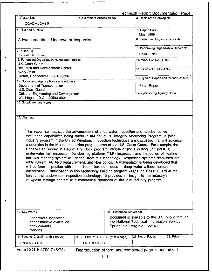
This report summarizes the advancement of underwater inspection and nondestructiveevaluation capabilities being made in the Structural Integrity Monitoring Program, a jointindustry program in the United Kingdom. Inspection techniques are discussed that will advancecapabilities in the Marine Inspection program area of the U.S. Coast Guard. For example, theUnderwater Survey in Lieu of Dry Dock program, mobile offshore drilling unit (MODU)underwater hull inspection, tension leg platform (TLP) inspection and inspection of floatingfacilities mooring system will benefit from this technology. Inspection systems discussed areeddy current, AC field measurement, and fiber optics. A manipulator is being developed thatwill perform inspection with these inspection techniques in deep water without humanintervention. Participation in this technology building program keeps the Coast Guard at theforefront of underwater inspection technology. It provides an insight to the industry'sviewpoint through contact with commercial sponsors of the joint industry program.
17. Key Words 18. Distribution Statement
underwater inspection Document is available to the U.S. public throughnondestructive evaluation the National Technical Information Service,eddy currents Springfield, Virginia 22161robotics
19. Security Clas, if. (of this report) 20. SECURITY CLASSIF. (of this page) 21. No. of Pages 22. Price
UNCLASSIFIED UNCLASSIFIED
Form DOT F 1700.7 (8/72) Reproduction of form and completed page is authorizediii
Q)
0 o-
E a4
.4- m ~ Cl 0 u m
'a M- to - ocu .01V) C, C4 'oom-0 0 00 N 0 1
E -3
U, cc 6o - o 6 j c -_
Q) 0W (0
0U ,, -L . 2
Q)l (D ( 00 -u E
0 EE 01E0
E I
-;z aaE E =o U
LL CLE E 0E E~ --CL E EE E wNE .z U
0 z zL~ oz SL 9L LL 9L Sk VL SL L LL O1 6 9 9
o 1 8 7 6 5 4 3 2 1 inches
Eml E EE E E u - .
LI) 0 IC Y
-~~~ EE.u
4- -ov )O)4) 0EEEa 4
=. zo -di6 cj S2. E 866 '
o) Q/ u
w CC< 0)C P C
o 0L 0)t
4-~ C~0 0
NC E
Q. .0 C. 0 uZE U, c rU
ivz
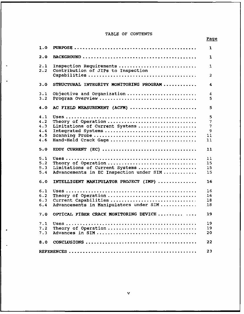
TABLE OF CONTENTS
Page
1.0 PURPOSE................................................. 1
2.0 BACKGROUND ......................................... 1
2.1 Inspection Requirements ................................ 12.2 Contribution of JIPs to Inspection
Capabilities ....................................... 2
3.0 STRUCTURAL INTEGRITY MONITORING PROGRAM .............. 4
3.1 Objective and Organization .............................. 43.2 Program Overview ................................... 5
4.0 AC FIELD MEASUREMENT (ACFM) ............................ 5
4.1 Uses ............................................... 54.2 Theory of Operation ................................ 74.3 Limitations of Current Systems ........................ 74.4 Integrated Systems ................................. 94.5 Scanning Probe. ..................................... 114.6 Hand-Held Crack Gage................................ 11
5.0 EDDY CURRENT (EC) .................................. 11
5.1 Uses ............................................... 115.2 Theory of Operation ................................ 155.3 Limitations of Current Systems ........................ 155.4 Advancements in EC Inspection under SIM .............. 15
6.0 INTELLIGENT MANIPULATOR PROJECT (IMP) ................ 16
6.1 Uses ............................................... 166.2 Theory of Operation .................................. 166.3 Current Capabilities ............................... 186.4 Advancements in Manipulators under SIM ................ 18
7.0 OPTICAL FIBER CRACK MONITORING DEVICE ............. ... 19
7.1 Uses ............................................... 197.2 Theory of Operation ................................ 197.3 Advances in SIM .................................... 20
8.0 CONCLUSIONS ........................................ 22
REFERENCES .............................................. 23
v
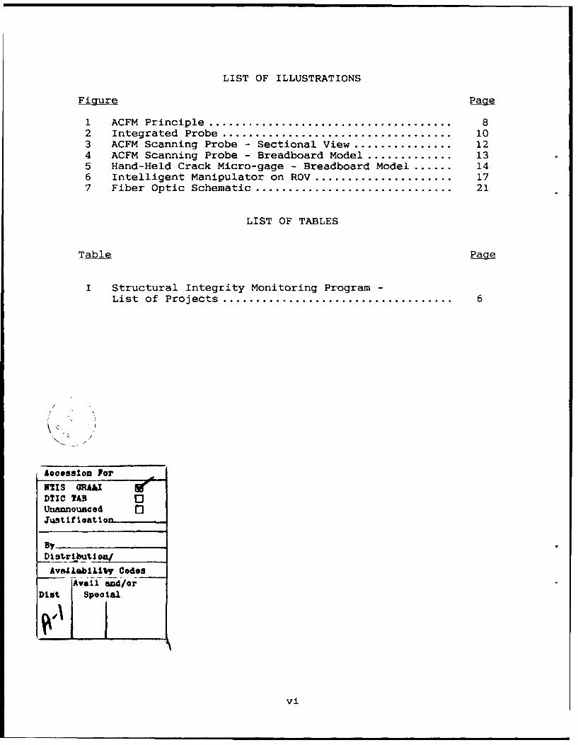
LIST OF ILLUSTRATIONS
Figure Page
1 ACFM Principle ..................................... 82 Integrated Probe ................................... 103 ACFM Scanning Probe - Sectional View ................. 124 ACFM Scanning Probe - Breadboard Model ............... 135 Hand-Held Crack Micro-gage - Breadboard Model ....... 146 Intelligent Manipulator on ROV ........................ 177 Fiber Optic Schematic .............................. 21
LIST OF TABLES
Table Page
I Structural Integrity Monitoring Program -List of Projects ................................... 6
Aooossion For
NTI S ;RA&1DTIC TADUnannouncedJistifreation
By_
Di stribut~nAvaJ.iblilby Codes
j vail and/orDiet Speolal
vi
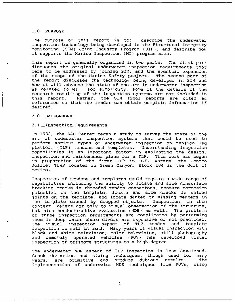
1.0 PURPOSE
The purpose of this report is to: describe the underwaterinspection technology being developed in the Structural IntegrityMonitoring (SIM) Joint Industry Program (JIP), and describe howit supports the Marine Inspection (MI) program area.
This report is generally organized in two parts. The first partdiscusses the original underwater inspection requirements thatwere to be addressed by joining SIM, and the eventual expansionof the scope of the Marine Safety project. The second part ofthe report discusses the technology being developed in SIM andhow it will advance the state of the art in underwater inspectionas related to MI. For simplicity, some of the details of theresearch resulting of the inspection systems are not included inthis report. Rather, the SIM final reports are cited asreferences so that the reader can obtain complete information ifdesired.
2.0 BACKGROUND
2.1 Inspection Pecuirements
In 1983, the R&D Center began a study to survey the state of theart of underwater inspection systems that could be used toperform various types of underwater inspection on tension legplatform (TLP) tendons and templates. Understanding inspectioncapabilities is an important factor in evaluating the design,inspection and maintenance plans for a TLP. This work was begunin preparation of the first TLP in U.S. waters, the ConocoJolliet TLWP located in Green Canyon, Block 184 in the Gulf ofMexico.
Inspection of tendons and templates could require a wide range ofcapabilities including the ability to locate and size nonsurfacebreaking cracks in threaded tendon connectors, measure corrosionpotential on the template, locate and size cracks in weldedjoints on the template, and locate dented or missing members inthe template caused by dropped objects. Inspection, in thiscontext, refers not only to visual observation of the structure,but also nondestructive evaluation (NDE) as well. The problemsof these inspection requirements are complicated by performingthem in deep water where divers are expensive or not practical.The visual inspection aspect of TLP tendon and templateinspection is well in hand. Many years of visual inspection withblack and white television, color television, still photographyand remo-ely operated vehicles (ROV) has developed visualinspection of offshore structures to a high degree.
The underwater NDE aspect of TLP inspection is less developed.Crack detection and sizing techniques, though used for manyyears, are primitive and produce dubious results. Theimplementation of underwater NDE techniques from ROVs, using
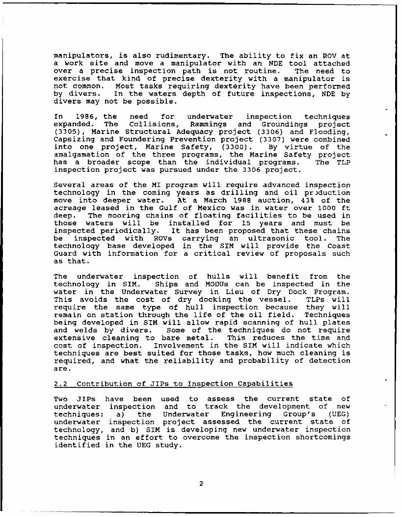
manipulators, is also rudimentary. The ability to fix an ROV ata work site and move a manipulator with an NDE tool attachedover a precise inspection path is not routine. The need toexercise that kind of precise dexterity with a manipulator isnot common. Most tasks requiring dexterity have been performedby divers. In the waters depth of future inspections, NDE bydivers may not be possible.
In 1986, the need for underwater inspection techniquesexpanded. The Collisions, Rammings and Groundings project(3305), Marine Structural Adequacy project (3306) and Flooding,Capsizing and Foundering Prevention project (3307) were combinedinto one project, Marine Safety, (3300). By virtue of theamalgamation of the three programs, the Marine Safety projecthas a broader scope than the individual programs. The TLPinspection project was pursued under the 3306 project.
Several areas of the MI program will require advanced inspectiontechnology in the coming years as drilling and oil pr)ductionmove into deeper water. At a March 1988 auction, 43% of theacreage leased in the Gulf of Mexico was in water over 1000 ftdeep. The mooring chains of floating facilities to be used inthose waters will be installed for 15 years and must beinspected periodically. It has been proposed that these chainsbe inspected with ROVs carrying an ultrasonic tool. Thetechnology base developed in the SIM will provide the CoastGuard with information for a critical review of proposals suchas that.
The underwater inspection of hulls will benefit from thetechnology in SIM. Ships and MODUs can be inspected in thewater in the Underwater Survey in Lieu of Dry Dock Program.This avoids the cost of dry docking the vessel. TLPs willrequire the same type of hull inspection because they willremain on station through the life of the oil field. Techniquesbeing developed in SIM will allow rapid scanning of hull platesand welds by divers. Some of the techniques do not requireextensive cleaning to bare metal. This reduces the time andcost of inspection. Involvement in the SIM will indicate whichtechniques are best suited for those tasks, how much cleaning isrequired, and what the reliability and probability of detectionare.
2.2 Contribution of JIPs to Inspection Capabilities
Two JIPs have been used to assess the current state ofunderwater inspection and to track the development of newtechniques: a) the Underwater Engineering Group's (UEG)underwater inspection project assessed the current state oftechnology, and b) SIM is developing new underwater inspectiontechniques in an effort to overcome the inspection shortcomingsidentified in the UEG study.
2
UEG Inspection Project (Ref. 1) - Early in the TLP tendon andtemplate inspection survey study, it became obvious tha the bulkof underwater inspection knowledge and experience is in thecountries around the North Sea where regulatory inspectionrequirements have driven the development of underwater inspectionsystems much faster than in the U.S. To gain access to theinformation in that area, the R&DC joined the UEG project"Underwater Inspection and Inspection Philosophy for OffshorePlatforms." UEG is located in London and has extensive offshoreexperience around the North Sea.
This program, managed by UEG, addresses the relationship ofdesign, maintenance and inspection in offshore platforms and iscomprised of approximately eight individual studies. The reasonfor joining this program was primarily for the study on the stateof the art of underwater inspection systems for conventionalsteel jacket platforms, concrete platforms and TLPs. Since thisprogram was conducted in the United Kingdom (UK) and since thebody of knowledge on underwater inspection systems is centeredthere, joining that program would contribute significantly to theTLP tendon inspection study.
The UEG underwater inspection study concluded that there is verylittle reliable performance data on underwater inspectionsystems. Manufacturers have been building systems, contractorshave been using these systems and owners have been acceptingresults from systems when no one really knows how well thesesystems work. There have been almost no detailed probability ofdetection (POD) trials in which the performance of systems areestimated using scientific methods.
Structural Integrity Monitoring (SIM) program - Because there isso little performance information on underwater inspectionequipment and because that industry lacks understanding of thecapability and use of their equipment, the R&DC needed a means oftracking current developments of new inspection systems. Toacccmplish this, the R&D Center became a sponsor of SIM. Twelveunderwater inspection techniques are being developed in thisprogram for eventual use on offshore structures. Being involvedwith the development of these systems "from the ground up" willprovide the Coast Guard with an understanding of the inherentcapabilities and limitations of the systems as well as the typesof evaluations that should be performed to demonstrate theeffectiveness of them. The Coast Guard will, in effect, go upthe learning curve with the manufacturers (also sponsors of thisprogram) who will be marketing the technology to platform ownerswho will present these systems to the Coast Guard during planreview. Participating in SIM also provides an insight to thepoint of view of the commercial inspection industry because theSteering Committee of 16 members has 12 commercial sponsors.
The SIM program contains an intelligent manipulator project thatis developing a manipulator and controls for use with NDEequipment in deep water without divers. The manipulator is
3
driven by a computer that positions the inspection device at theinspection site and passes it along a predetermined inspectionpath such as a weld. This capability could be used to inspectTLP tendons and templates and floating facilities moorings wheredivers are expensive or not feasible because of other physicalconstraints such as water depth. Diverless inspectioncapabilities may also yield more accurate and repeatableinspection results by removing the human factor.
In summary, the UEG inspection program provided astate-of-the-art survey of underwater inspection systems'performance; determining that there really is essentially noreliable performance information, SIM was joined to be involvedwith the improvement or development of underwater inspectionsystems.
This section has been a brief discussion of the history of theseJIPs and how they supported the specific requirements of the TLPinspection study and more recently the broader scope of theMarine Inspection Program. The remainder of this report willfocus on the technology being developed in SIM. But first,programmatic aspects of SIM are discussed briefly to provide acomplete view of that program, how it functions and the type ofexposure it provides the Coast Guard.
3.0 STRUCTURAL INTEGRITY MONITORING PROGRAM
3.1 Objectives and Organization
The objective of SIM is to improve current underwater inspectionpractices and procedures in offshore engineering by developingnew or improved NDE techniques for crack monitoring and remotecontinuous monitoring systems.
The program includes projects on techniques currently used inindustry such as AC field measurement (ACFM), eddy current (EC)and acoustic emission. Phased array ultrasonics, optical fibersand hydrogen sensors are being developed but have not yet beenused offshore. SIM includes the development of a variety ofinspection techniques because the industrial sponsors feel thatthey will be using a mix of inspection techniques in the nextdecade just as they have in the past decade.
The SIM is a consortium of 5 UK universities. The total fundingfor the program is approximately $850K, 60% of which is providedby the Science and Engineering Research Council (SERC) in theUK. The SERC commits its share of the funds if the managinginstitution can interest commercial sponsors in joining theprogram and providing the remaining 40% of the funds. Thisensures that the R&D conducted by the universities is relevantto offshore needs because many of the sponsors are involvedbecause they want to commercially exploit the new technology.This connection to reality is also evident when the sponsorsdecide at the end of each two-year program which project will be
4
continued in the next phase and which will be dropped. Thecurrent program is sponsored by 16 different companies from fivecountries. The SIM is a continuing program that operates in two-year phases. The Coast Guard sponsored Phase II (1985-1987) andsponsors Phase III (1987-1989). The cost to the Coast Guard isapproximately SIIK per year.
3.2 Program Overview
The emphasis in the following overview of the projects is onthose that were continued from Phase II to Phase III because oftechnical merit (i.e., high probability of success). Theprojects of both Phases are shown in Table I. Some of theinspection techniques in these projects are more advanced thanothers and some may never reach commercial development. Theobjective of all the Phase III projects is to work increasinglytoward satisfying the long term NDE requirements of industry.These are techniques that can be:
a. deployed from a ROVb. operated in a rapid scanning modec. operated with increased stand-off from the structure
thereby reducing the need for extensive cleaning
The SIM projects discussed below are those that will have thebroadest application to the MI mission and offer an advancedcapability not currently available. While the technicaldevelopment of these systems are advancing, none has developed tothe level where commercialization is appropriate.
4.0 AC FIELD MEASUREMENT (ACFM)
4.1 Uses
ACFM is a surface crack depth measurement technique. It has beendeveloped in England and systems have been introduced forunderwater use by OSEL and Det Norske Veritas. They areextensions of a system developed for manufacturing plantinspection purposes. ACFM is conventionally used to measure thedepth of a surface crack that has been located by anotherunderwater NDE technique. Through the work in this program, ACFMis also being developed to scan over metal surfaces to locate aswell as measure the depth of surface cracks in metal plates andwelded joints.
ACFM systems could be used by a diver to locate and size cracksin the hull plates and welds of ships (as in the UnderwaterSurvey in Lieu of Dry Dock program) and MODUs. In the nearfuture, ACFM systems will be deployed by ROV with a manipulatorfor inspection in water depths beyond diver capabilities. Thismay include the inspection for surface cracks in the mooringchains of floating offshore facilities. These moorings will bedeployed for 15 years and will be inspected in place in severalthousand feet of water.
5
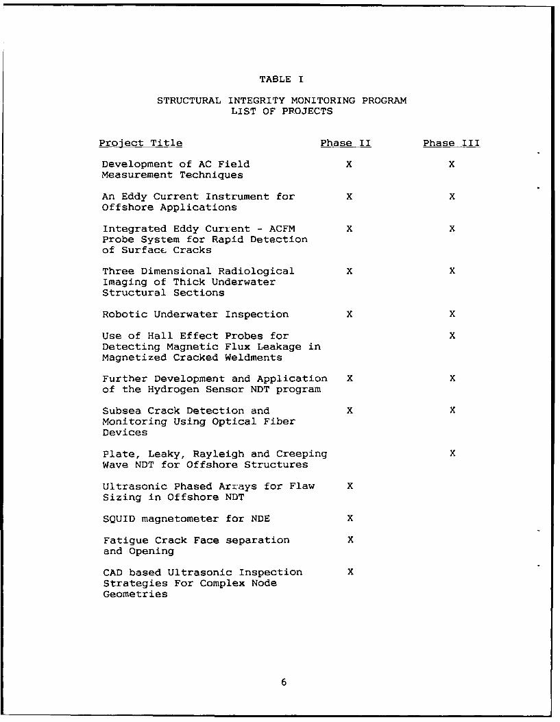
TABLE I
STRUCTURAL INTEGRITY MONITORING PROGRAMLIST OF PROJECTS
Project Title Phase II Phase III
Development of AC Field X XMeasurement Techniques
An Eddy Current Instrument for X XOffshore Applications
Integrated Eddy Current - ACFM X XProbe System for Rapid Detectionof Surface Cracks
Three Dimensional Radiological X XImaging of Thick UnderwaterStructural Sections
Robotic Underwater Inspection X X
Use of Hall Effect Probes for XDetecting Magnetic Flux Leakage inMagnetized Cracked Weldments
Further Development and Application X Xof the Hydrogen Sensor NDT program
Subsea Crack Detection and X XMonitoring Using Optical FiberDevices
Plate, Leaky, Rayleigh and Creeping XWave NDT for Offshore Structures
Ultrasonic Phased Arrays for Flaw XSizing in Offshore NDT
SQUID magnetometer for NDE X
Fatigue Crack Face separation Xand Opening
CAD based Ultrasonic Inspection XStrategies For Complex NodeGeometries
6
4.2 Theory of Operation
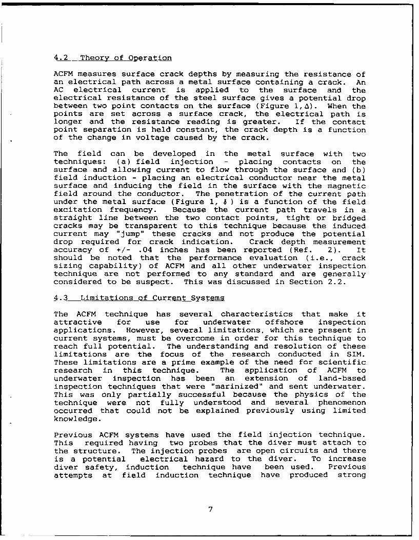
ACFM measures surface crack depths by measuring the resistance ofan electrical path across a metal surface containing a crack. AnAC electrical current is applied to the surface and theelectrical resistance of the steel surface gives a potential dropbetween two point contacts on the surface (Figure l,A). When thepoints are set across a surface crack, the electrical path islonger and the resistance reading is greater. If the contactpoint separation is held constant, the crack depth is a functionof the change in voltage caused by the crack.
The field can be developed in the metal surface with twotechniques: (a) field injection - placing contacts on thesurface and allowing current to flow through the surface and (b)field induction - placing an electrical conductor near the metalsurface and inducing the field in the surface with the magneticfield around the conductor. The penetration of the current pathunder the metal surface (Figure 1, 6 ) is a function of the fieldexcitation frequency. Because the current path travels in astraight line between the two contact points, tight or bridgedcracks may be transparent to this technique because the inducedcurrent may "jump" these cracks and not produce the potentialdrop required for crack indication. Crack depth measurementaccuracy of +/- .04 inches has been reported (Ref. 2). Itshould be noted that the performance evaluation (i.e., cracksizing capability) of ACFM and all other underwater inspectiontechnique are not performed to any standard and are generallyconsidered to be suspect. This was discussed in Section 2.2.
4.3 Limitations of Current Systems
The ACFM technique has several characteristics that make itattractive for use for underwater offshore inspectionapplications. However, several limitations, which are present incurrent systems, must be overcome in order for this technique toreach full potential. The understanding and resolution of theselimitations are the focus of the research conducted in SIM.These limitations are a prime example of the need for scientificresearch in this technique. The application of ACFM tounderwater inspection has been an extension of land-basedinspection techniques that were "marinized" and sent underwater.This was only partially successful because the physics of thetechnique were not fully understood and several phenomenonoccurred that could not be explained previously using limitedknowledge.
Previous ACFM systems have used the field injection technique.This required having two probes that the diver must attach tothe structure. The injection probes are open circuits and thereis a potential electrical hazard to the diver. To increasediver safety, induction technique have been used. Previousattempts at field induction technique have produced strong
7
Probe
MetalC eSurfaceCrack
Figure 1ACFM Principle
8
spurious signals that are believed to enter the system throughthe contact probes, and signal and power cables from sourceselsewhere on the structure.
Previous ACFM systems were not developed to the level thatachieved accurate interpretation of crack size from fieldmeasurements.
To overcome these limitations, two different ACFM systems havebeen developed in SIM, each with a somewhat different objective.Both systems have advanced the capability of this inspectiontechnique. The two systems are discussed below in the contextof the shortcomings in the previous section.
4.4 Integrated System
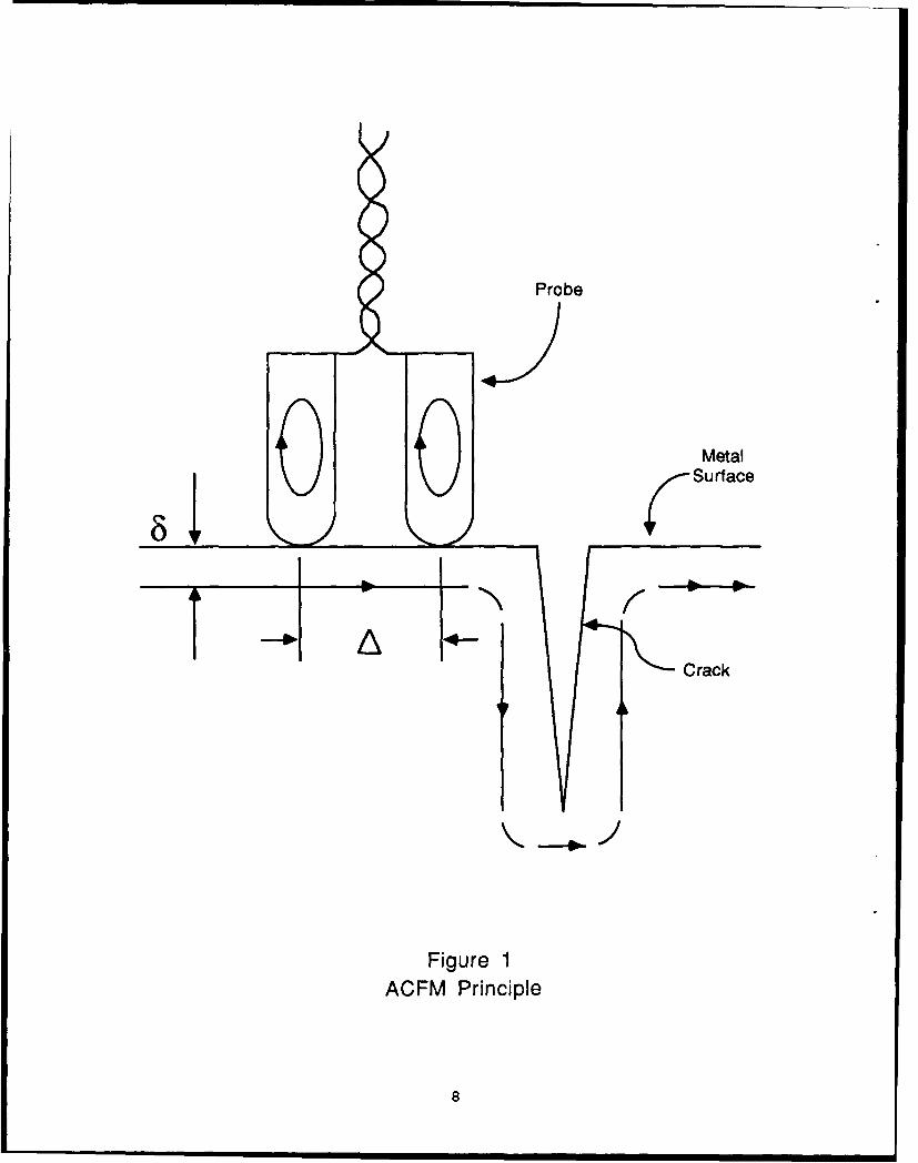
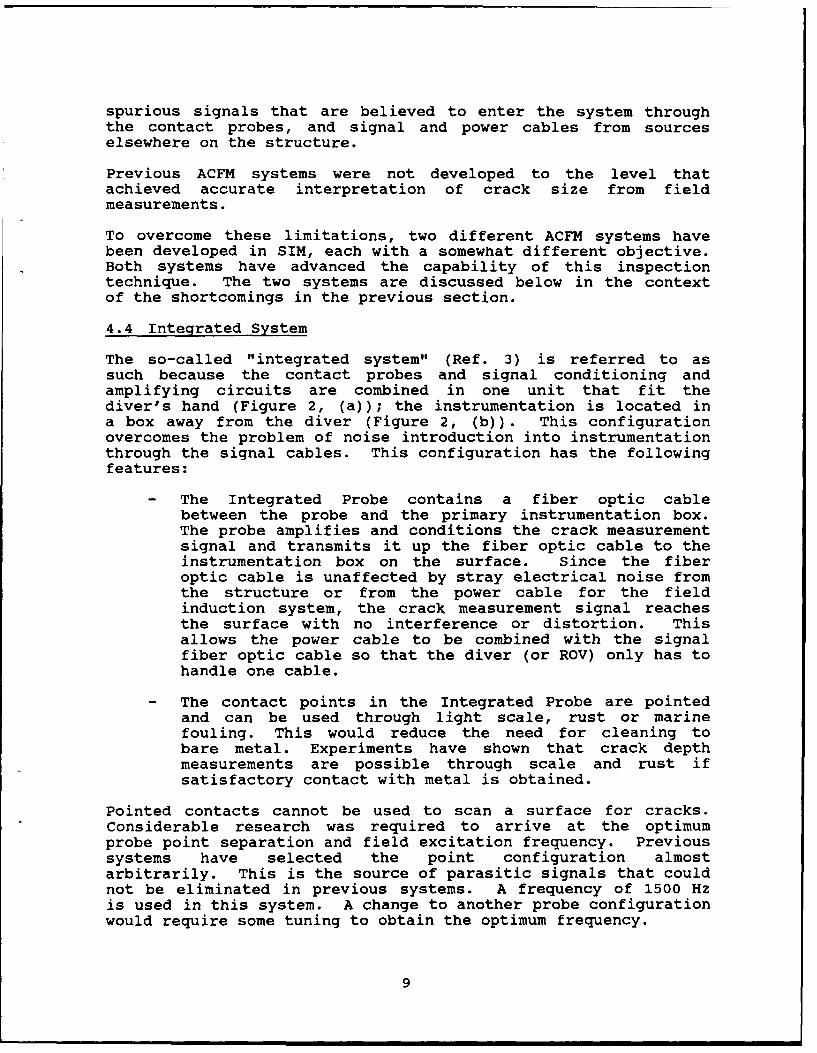
The so-called "integrated system" (Ref. 3) is referred to assuch because the contact probes and signal conditioning andamplifying circuits are combined in one unit that fit thediver's hand (Figure 2, (a)); the instrumentation is located ina box away from the diver (Figure 2, (b)). This configurationovercomes the problem of noise introduction into instrumentationthrough the signal cables. This configuration has the followingfeatures:
- The Integrated Probe contains a fiber optic cablebetween the probe and the primary instrumentation box.The probe amplifies and conditions the crack measurementsignal and transmits it up the fiber optic cable to theinstrumentation box on the surface. Since the fiberoptic cable is unaffected by stray electrical noise fromthe structure or from the power cable for the fieldinduction system, the crack measurement signal reachesthe surface with no interference or distortion. Thisallows the power cable to be combined with the signalfiber optic cable so that the diver (or ROV) only has tohandle one cable.
- The contact points in the Integrated Probe are pointedand can be used through light scale, rust or marinefouling. This would reduce the need for cleaning tobare metal. Experiments have shown that crack depthmeasurements are possible through scale and rust ifsatisfactory contact with metal is obtained.
Pointed contacts cannot be used to scan a surface for cracks.Considerable research was required to arrive at the optimumprobe point separation and field excitation frequency. Previoussystems have selected the point configuration almostarbitrarily. This is the source of parasitic signals that couldnot be eliminated in previous systems. A frequency of 1500 Hzis used in this system. A change to another probe configurationwould require some tuning to obtain the optimum frequency.
9
Contact Circuitry Fiber OpticPoints -Cable
a.
b.
Figure 2Integrated Probe
10
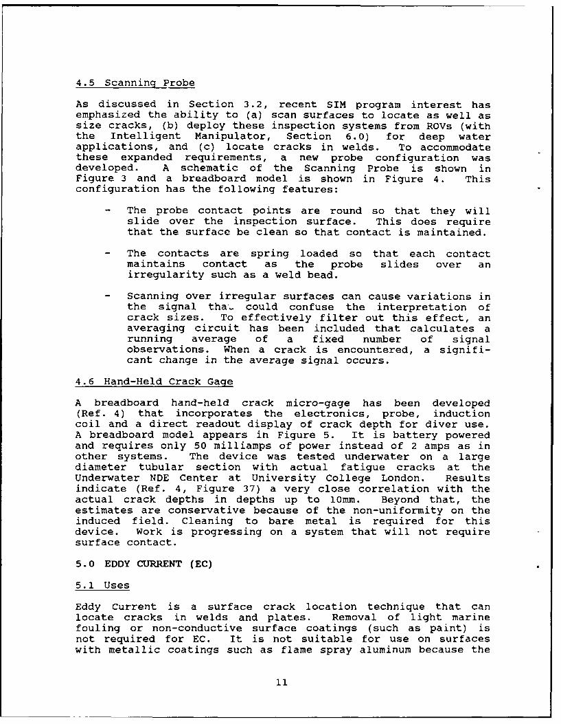
4.5 Scanning Probe
As discussed in Section 3.2, recent SIM program interest hasemphasized the ability to (a) scan surfaces to locate as well assize cracks, (b) deploy these inspection systems from ROVs (withthe Intelligent Manipulator, Section 6.0) for deep waterapplications, and (c) locate cracks in welds. To accommodatethese expanded requirements, a new probe configuration wasdeveloped. A schematic of the Scanning Probe is shown inFigure 3 and a breadboard model is shown in Figure 4. Thisconfiguration has the following features:
- The probe contact points are round so that they willslide over the inspection surface. This does requirethat the surface be clean so that contact is maintained.
- The contacts are spring loaded so that each contactmaintains contact as the probe slides over anirregularity such as a weld bead.
- Scanning over irregular surfaces can cause variations inthe signal tha-. could confuse the interpretation ofcrack sizes. To effectively filter out this effect, anaveraging circuit has been included that calculates arunning average of a fixed number of signalobservations. When a crack is encountered, a signifi-cant change in the average signal occurs.
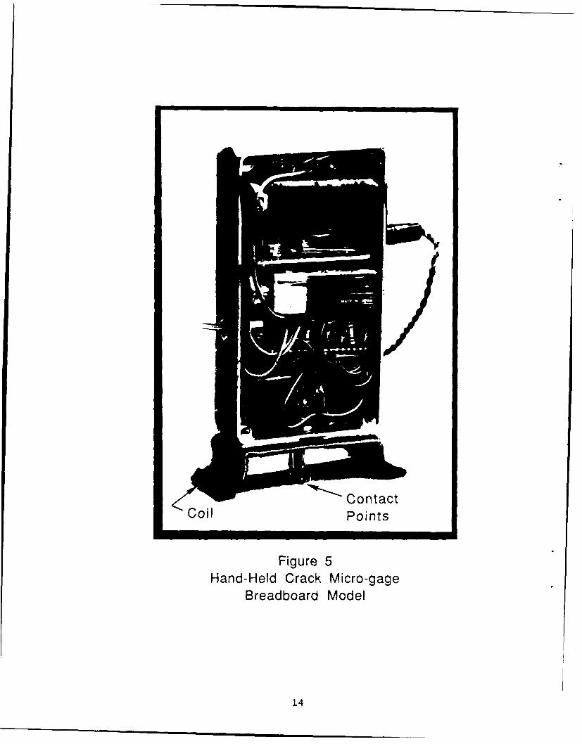
4.6 Hand-Held Crack Gage
A breadboard hand-held crack micro-gage has been developed(Ref. 4) that incorporates the electronics, probe, inductioncoil and a direct readout display of crack depth for diver use.A breadboard model appears in Figure 5. It is battery poweredand requires only 50 milliamps of power instead of 2 amps as inother systems. The device was tested underwater on a largediameter tubular section with actual fatigue cracks at theUnderwater NDE Center at University College London. Resultsindicate (Ref. 4, Figure 37) a very close correlation with theactual crack depths in depths up to 10mm. Beyond that, theestimates are conservative because of the non-uniformity on theinduced field. Cleaning to bare metal is required for thisdevice. Work is progressing on a system that will not requiresurface contact.
5.0 EDDY CURRENT (EC)
5.1 Uses
Eddy Current is a surface crack location technique that canlocate cracks in welds and plates. Removal of light marinefouling or non-conductive surface coatings (such as paint) isnot required for EC. It is not suitable for use on surfaceswith metallic coatings such as flame spray aluminum because the
11
4-rn-rn---50 mm
perspex
spring signal //
wires
75 mm
62 mm
acetal
silicon one of the tworubber wires of the inducing
mechanism
stainless 4 Contact ProbesteelPrb
*19 mm -
Figure 3ACFM Scanning Probe
Sectional View
12
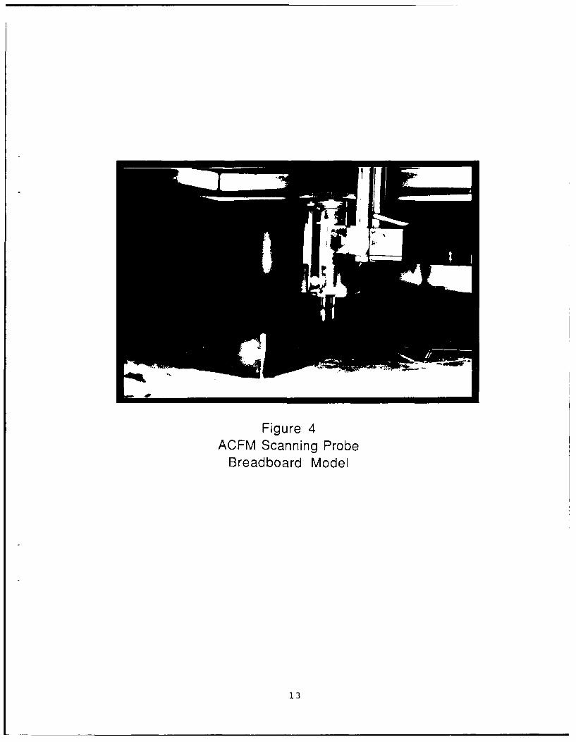
Figure 4ACFM Scanning Probe
Breadboard Model
13
Contact
coil Points
Figure 5Hand-Held Crack Micro-gage
Breadboard Model
14
magnetic field is displaced through the coating instead ofaround the crack resulting in no crack indication.
EC can be used to locate surface cracks above or below the waterline in ship hulls, TLPs, MODU's and deep water floatingfacilities.
5.2 Theory of Operation
EC inspection detects surface or near-surface defects byestablishing an oscillating magnetic field on the metal surfaceand detecting the perturbation of the magnetic field caused bythe defect. The magnetic field is induced in the surface byplacing a coil next to the surface; perturbations in themagnetic field are sensed by another coil which is passed overthe inspection area. The magnetic field is perturbed bycracks, voids, inclusions, and changes in permeability of theparent metal and weld material in the heat affected zone (HAZ).One of the primary shortcomings of conventional EC systems isthe difficulty in separating valid defect indications fromchanges in metal properties (i.e., permeability).
EC is somewhat different from the ACFM technique discussed inSection 4.0 in that the probe does not necessarily have to makecontact with the surface.
5.3 Limitation of Current Systems
The change in permeability across the HAZ and the sensitivity tolift-off (i.e., the spacing between the probe and the metalsurface) are the root of the limitation of current EC systems.
Conventional systems developed for underwater inspection use oneprobe to scan across the inspection area. The change in thepermeability of the ferritic steel (often found in offshorestructures) requires constant tuning by the operator (who istopside) and communication between the operator and the diver.The very large change in permeability between the weld and HAZmay mask a defect. For this reason, EC is considered lessreliable than other conventional techniques like magneticparticle inspection. Conventional EC systems require cleaningto bare metal so that the lift-off can be kept constant.
5.4 Advancement in EC Inspection Under SIM
The EC system (Ref. 5) developed in SIM has resolved thepermeability variation problem by developing a rectangularmatrix array probe of 16 eddy current coils that maps thevariation of metal properties under the array. This techniquecan determine if the variations in permeability from onelocation to another is the cause of gradual changes in metalproperties or a crack indication. A 16-element array prototypeis approximately 3/4-inches square with 16 1/16-inch diameter
15
coils arranged in a square matrix. The development of a 16-element array required the development of new computer aidedinstrumentation for probe excitation and sensing, switching anddata storage and analysis.
The system has a lift-off sensor in the probe that provides agraphic indication of lift-off in the instrumentation. It isimportant for the operator to know that the probe is withinacceptable limits because the magnetic field strength, andtherefore the crack detection, will be affected. The lift-offfor the present probe is 3/16-inch. Another approach to insurecorrect lift-off on surface of irregular shapes is to configurethe probe so that it conforms to the surface. This can be donefor welds and other shapes. This is an objective of the currentSIM project.
6.0 INTELLIGENT MANIPULATOR PROJECT (IMP)
6.1 Uses
The IMP is developing a robotic manipulator for cleaning and NDEof welded tubular joints in offshore structures without the useof divers or other substantial human intervention (Ref. 6).This technique has application to the inspection of the mooringchains and terminations on floating facilities, and tension legplatforms that will be moored in deep water for many years.
6.2 Theory of Operation
To accomplish cleaning and inspection tasks in deep water, themanipulator will be mounted on an ROV or an ROV-transportedplatform and attached to the structure adjacent to the weldedtubular joint to be cleaned and inspected (Figure 6). After themanipulator is secured to the structure and its locationdetermined from a reference mark, the manipulator begins acomputer-driven routine in which the manipulator determines itsprecise location with regard to the tubular members making upthe joint to be inspected. To accomplish this, the manipulatoris extended until it touches one of the tubular members. Thecomputer records the location in space of that contact point.The manipulator then retracts and extends until it touchesanother point near the first point; the location of that pointin space is recorded. This procedure is repeated to establishthe location of several "patches" in space; a patch is a smallarea on the surface of the tubular defined by three or fourpoints that the manipulator has located. The computer thenproceeds to locate other patches on the other tubular members inthe same manner as the first. Having located several patches onthe adjacent tubular members, the computer routine calculateswhere the two members meet, and therefore, where the weld is.Having determined the location of the welded joint, themanipulator goes back and traces the same path with a cleaningdevice to expose the weld, and repeats the process with an NDEprobe to locate and size cracks.
16
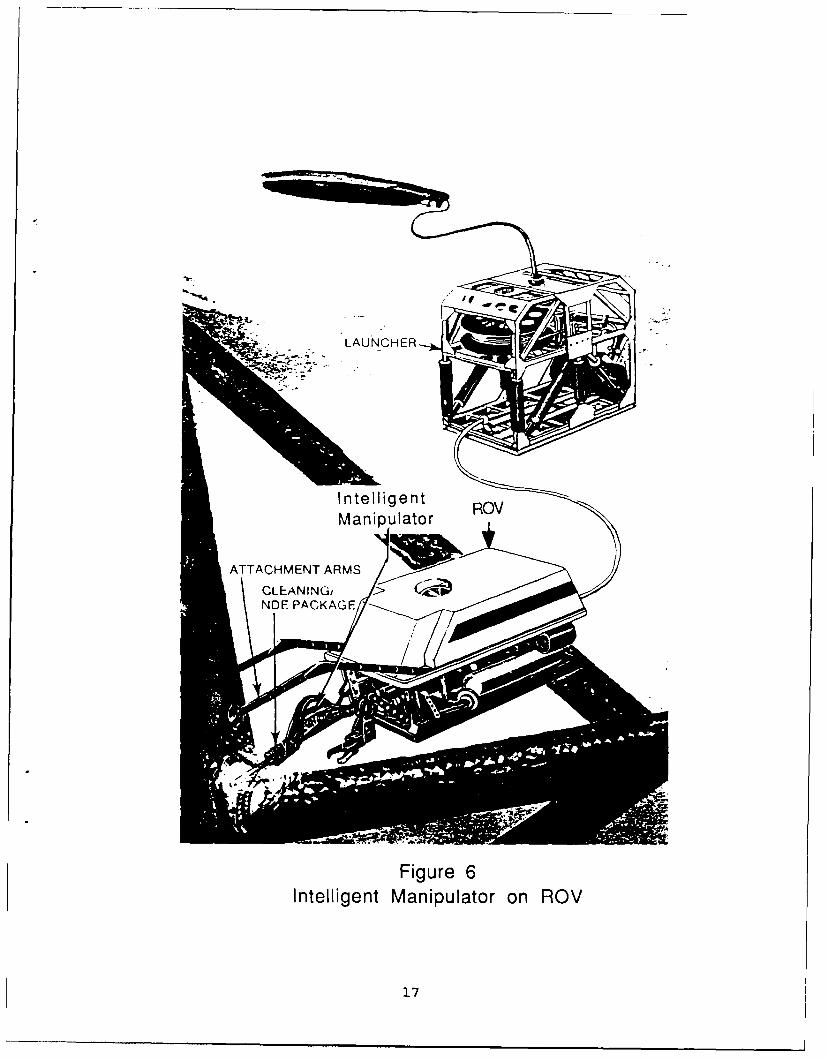
Fneligure 6O
Intelligent Manipulator on ROV
17
During the scanning of the NDE probe over the weld, themanipulator control system is recording the location of the NDEprobe. If a defect is indicated, the manipulator controlsrecord the location. That allows the manipulator to return tothe same location on subsequent inspections to determine if thecrack is growing.
6.3 Current Capabilities
Current applications of manipulators in underwater inspectionand cleaning tasks use the master/slave configuration ofcontrol. The person operating the manipulator is located on thestructure or support vessel and views the work site over closedcircuit television (CCTV). He sits on a device that has an arm(called the master) much like the manipulator (called the slave)at the underwater work site. The control circuit links themaster and slave so that the slave mimics the motion of themaster. The operator, viewing the work site on the CCTV, moveshis master arm as if he were at the work site and themanipulator is his arm. Feedback systems in the slave addresistance to the master arm so that the operator can feel thatthe slave is against an immovable object. This gives theoperator some sense of touch through the manipulator.
The master/slave system is slow because the operator views thework site through CCTV which is a two dimensional representationof a three dimensional situation. This requires a high level ofconcentration by the operator; most operators can work only 2-4hours before requiring relief. Three-dimensional viewingsystems have been developed that improve depth perception butcause eye strain and headaches in many operators.
The positional accuracy of conventional manipulators is adequatefor visual inspection, cleaning and magnetic particleinspection. However, for EC, ACPD and other more precise NDEtechniques, a more precise manipulator is required so that theprobe is moved across the weld bead with greater accuracy andthe crack can be relocated in subsequent inspections. Thisrequires development of both sensors (to determine distances)and control system (i.e., software) routines to computepositions.
6.4 Advancements in Manipulators Under SIM
The general advancements in manipulator technology by SIM arelargely described in the Theory of Operation section above,because of the uniqueness of this project. Manipulatortechnology has advanced from master/slave operation into thefield of semi-automatic operation for this specific application.
In addition to the computer control system algorithms, majordevelopments of this project that have increased the precisionare the tactile sensors and laser range techniques. The tactilesensors are used during the "patch" process in which the tubular
18
member surfaces are being located. Greater accuracy in thetactile sensor provides greater accuracy in the tubular jointmathematical model in the computer control system. Tactilesensors are configured to penetrate light marine fouling.
The introduction of laser ranging devices is increasing theprecision of the ranipulator by giving it real time up-dates ofthe distance from the manipulator to the surface. This can becompared with the distance calculated by the control systemalgorithm and a correction applied. The laser ranging techniqueis also being utilized to trace the shape and location ofthe weld bead. This allows the control systems to key on theshape of the weld bead for tracking purposes.
7.0 OPTICAL FIBER CRACK MONITORING DEVICE
7.1 Uses
A fiber optic crack monitoring device is a witness techniquethat continually monitors a crack to indicate when the crack haspropagated beyond a specified point (Ref. 7).
When a crack is located by an inspection technique, a fiberoptic crack monitoring device can be placed across the crack.As loading conditions increase and the crack begins to grow, thecrack monitoring device is fractured by the crack and causes anindication in the instrumentation on the platform. This type ofcrack monitoring is most effective in locations on a structurewhere diver observation is not possible until after the extremeloading conditions subside or perhaps until the next scheduledinspection or maintenance occurs. This is the case, forexample, on offshore structures that are normally inspected inthe summer months when the weather is better. Cracks can bemonitored during the winter months between inspections.
7.2 Theory of Operation
The essence of fiber optics is the transmission of light througha small glass fiber with very low attenuation. Thischaracteristic is used as a witness device, that is, to indicateif a known condition has been exceeded (rather than to measure acondition). In a fiber optic crack monitoring device, the fibertransmits light until a condition is exceeded and the fiberbreaks interrlpting the light path.
A fiber optic crack monitoring device is a very simple systemwhich has as its sensing element a fiber optic "package." The"package" is analogous to a strain gage that is placed on alocation where the indication is required. It is an opticalfiber embedded in a resin matrix to give it rigidity. Thematrix is cemented to the steel surface over the crack tip thatis being monitored.
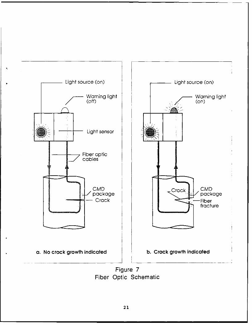
In practice, the light source transmits light down the fiber
19
optic cable through the package and back up the cable to theinstrumentation where a light sensor is located. The light paththrough the package to the light sensor remains intact and thereis no indication in the instrumentation (Figure 7a). When theloading conditions have caused the crack to grow and open, theoptical fiber in the package breaks and the light transmittedthrough the package is substantially reduced (Figure 7b). Thatreduction causes the light sensor in the instrumentation on theplatform to sound an alarm.
Fiber optic crack monitoring devices have the advantage thatthere is no interpretation of data required by the operator onthe platform; it is a go/no-go system. Fiber optic systems arenot sensitive to electrical noise as are other types of sensitivemeasurement systems because no electric cables are routed aroundthe structure where they are subject to a wide variety ofextraneous electrical noise. All signals in fiber optic systemsare transmitted by light through fiber optic cables which areunaffected by electricity.
Once placed over a crack on the structure, a fiber optic crackmonitoring device requires no further maintenance. Marinefouling can grow over it with no effect.
7.3 Advances in SIM
This project takes advantage of existing fiber optic technologyas much as possible. Mass production of fiber optic cables,terminations, instrumentation and other components for thetelecommunication industry has reduced cost and increasedavailability. The area of package development and adhesion isthe primary area of technical advancement made in this project.
Optical fiber has a breaking strain of approximately 5-7%. For afiber to be sensitive to the growth of small crack openings, thebraaking strain must be reduced to 0.5-1.0%. Several techniqueswere developed in SIM that degrades the fiber in a chemicalsolution and reduces the strain at failure. This processproduces notches uniformly distributed on the fiber surface whichact as stress raisers. The degraded fiber is then assembled in aresin matrix that comprised the crack monitoring device"package". Techniques were developed to produce packages thatare as thin as possible yet rugged because efficient transfer ofstrain from the steel surface to the fiber is essential for goodsensitivity. In a package applied to a flat surface, the fiber isapproximately 0.5mm from the surface.
Tests on flat surfaces indicate that crack openings of 50micrometers can be sensed and that the crack tip may be 20mm pastthe package before it fails. Monitoring weld toe cracks willreduce the sensitivity of the fiber optic crack monitoring devicebecause the uneven surface of the weld profile must be made flatwith resin before the package is affixed. Tests have showedthat every imm increase in resin halves the package
20
Light source (on) Light source (on)
Warning light Warning fight
(off) (on)
Light sensor
Fiber opticcables
aCMD Crack CMDSC package package
Crack -..-- Fiberfracture
a. No crack growth indicated b. Crack growth indicated
Figure 7Fiber Optic Schematic
21
sensitivity. Because of this, some of the tubular joints inoffshore structures will have a limited number of locations thatcannot be monitored.
The technique of applying the package underwater was developedin SIM. A high viscosity underwater epoxy was utilized that canbe applied to vertical or overhead surfaces without the epoxyrunning before the package is applied. One of the biggestproblems in the underwater application of the package is non-uniformity in the thickness of the epoxy layers used either tocreate a flat surface for the package or excess adhesive betweenthe package and the surface. This lack of control decreases thesensitivity of the package. This area is under continuingdevelopment.
8.0 CONCLUSIONS
SIM provides a window on the development of future underwaterwater inspection and NDE systems that will be used on ships andMODUs (to reduce the high cost of dry dock for inspection), andoffshore floating facilities as oil production moves into deeperwater. Given the rudimentary state of underwater inspectionsystems in general, the technology developed in this programrepresents a significant portion of all new information in thisfield.
SIM is a technology building program. While the development ofsome of these inspection systems requires years, the reports andexposure to the program provides technical input for theevaluation of inspection plans that are being submitted now forTLPs and other floating facilities that will remain on stationfor many years. Current program involvement provides a means ofassessing what is possible now and where the technology will bein five or ten years. Participation also indicates the types ofprocedures that should be undertaken to estimate systemperformance in a scientific manner so that the results arecreditable.
Participation on the Steering Committee provides an insight tothe thought process and viewpoint of the industry that isdeveloping and using these systems. While the research anddevelopment of these systems is executed by academicresearchers, the Steering Committee is composed of commercialoperators and oil companies expecting to implement thistechnology profitably. Participation provides exposure toindustry views which is considered in Coast Guard regulatoryactivities. An appreciation of industry viewpoints helps theCoast Guard meet its intent of not over-regulating the industry.
SIM provides a significant quality and quantity of research anddevelopment at a very nominal cost to the Coast Guard. Accessto $850K of research costs the Coast Guard $11K per year.
22
REFERENCES
1. "Guidance for Inspection of Offshore Structures," UEGStudy 1, November 1985.
2. Bitting, Kenneth R., Allen, Stephen J., Walker, Richard T.,Abe, George. "Tension Leg Platform Tendon and TemplateInspection - A Survey of Capabilities". U.S. Coast GuardResearch and Development Center, Final Report July 1985.
3. i.irshekar-Syahkal, D. "Rapid Detection of Surface BreakingCracks by ACFM Method". SIM II Project 4. University ofEssex. February 1988.
4. Collins, R., Michael, D.H. "Development of ElectromagneticMethods of Surface Defect Detection & Sizing." SIM IIProject 1. University College London, July 1987.
5. McNab, A., Thomson, J. "Eddy Current Instrumentation inOffshore Applications." SIM II Project 3. University ofStrathclyde, June 1987.
6. Broome, D.R., Hughes, G. "Development of InspectionTechniques Using a Subsea Manipulator." SIM II Project 6.University College London.
7. Hockenhull, B.S., Billingham, J. "Monitoring Fatigue Cracksin Tubular Joints with Optical Fibre Devices." SIM IIProject 5. Cranfield Institute of Technology.
23

BLANK]
244