Embed Size (px)
Citation preview

Cadence SPB: What's New in 16.6 Quarterly Incremental Release (QIR) 6
Cadence SPB: What’s New in 16.6 QIR 6 (HotFix 27)
This document describes the new features and enhancements in Cadence® SPB products in 16.6 Quarterly Incremental Release (QIR) 6. The products covered are:
■ Cadence SPB Products: Windows 8.1 Support
■ Allegro PCB Editor
■ Cadence SiP Layout and Allegro Package Designer (APD)
■ Allegro Design Entry HDL
■ Allegro FPGA System Planner
■ OrCAD Capture
■ Cadence PSpice
© 2014 Cadence, Allegro, OrCAD, and PSpice are registered trademarks of Cadence Design Systems, Inc. in the United States and/or other jurisdictions.
April 2014 13 Product Version 16.6
Cadence SPB: What's New in 16.6 Quarterly Incremental Release (QIR) 6Cadence SPB Products: Windows 8.1 Support
Cadence SPB Products: Windows 8.1 Support
Cadence® SPB products are now supported on Microsoft® Windows® 8.1.
Note: If your locking method is dongle, download and install the new License Manager (FLEX v11.11.1.1) that supports dongle drive installation for Windows 8.1. You need to restart the license server after installation to avoid compatibility issues.
April 2014 14 Product Version 16.6

Cadence SPB: What's New in 16.6 Quarterly Incremental Release (QIR) 6Allegro PCB Editor
Allegro PCB Editor
This document describes the new features and enhancements in Allegro® PCB Editor16.6 QIR 6.
■ IPC 2581 Stackup Exchange on page 16
■ Route Interconnect Optimization on page 17
❑ Auto Interactive Breakout Technology (Design Planning Option) on page 17
❑ Edit Vertex – Snap to 45 on page 18
❑ Remove Tuning (High Speed Option) on page 18
❑ Dynamic Rat Suppression on page 18
■ Productivity Enhancements on page 20
❑ Split Views on page 20
❑ Move Component with Slide Etch on page 21
❑ Drafting Updates on page 21
❑ Dimensioning on page 22
❑ File Locking Update on page 22
❑ Find by Query on page 23
❑ Unsupported Prototype Functionality on page 25
■ RF PCB Enhancements on page 26
❑ Autoplace Enhancements on page 26
❑ Layout Enhancements on page 28
April 2014 15 Product Version 16.6
Cadence SPB: What's New in 16.6 Quarterly Incremental Release (QIR) 6Allegro PCB Editor
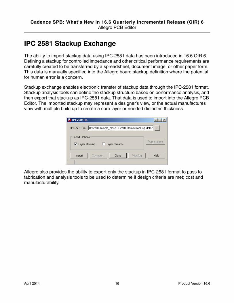
IPC 2581 Stackup Exchange
The ability to import stackup data using IPC-2581 data has been introduced in 16.6 QIR 6. Defining a stackup for controlled impedance and other critical performance requirements are carefully created to be transferred by a spreadsheet, document image, or other paper form. This data is manually specified into the Allegro board stackup definition where the potential for human error is a concern.
Stackup exchange enables electronic transfer of stackup data through the IPC-2581 format. Stackup analysis tools can define the stackup structure based on performance analysis, and then export that stackup as IPC-2581 data. That data is used to import into the Allegro PCB Editor. The imported stackup may represent a designer’s view, or the actual manufactures view with multiple build up to create a core layer or needed dielectric thickness.
Allegro also provides the ability to export only the stackup in IPC-2581 format to pass to fabrication and analysis tools to be used to determine if design criteria are met; cost and manufacturability.
April 2014 16 Product Version 16.6
Cadence SPB: What's New in 16.6 Quarterly Incremental Release (QIR) 6Allegro PCB Editor
Route Interconnect Optimization
■ Auto Interactive Breakout Technology (Design Planning Option) on page 17
■ Edit Vertex – Snap to 45 on page 18
■ Remove Tuning (High Speed Option) on page 18
■ Dynamic Rat Suppression on page 18
Auto Interactive Breakout Technology (Design Planning Option)
AiBT is an auto-interactive command designed to expedite the breakout of high pin count devices like BGAs and Connectors. It operates on a user-defined selection set of Interconnect Flow Planner Bundles or the Bundle's rats as its input. This input is used to define a pattern that tries to create the optimum channel utilization and layer distribution possible while intelligently sequencing the breakout routes at each end so not to create cross-overs when routing the trunk.
Additional user-controls that influence the breakout pattern include:
■ The Bundle's layer properties whether defined by layer-sets or user-choice on the Bundle's layer properties.
■ A Rat sequence can be created, edited or defined to create a specific entry/exit pattern for the Bundle. The Rat sequence can be used to define the exact pattern desired for both ends of the Bundle to implement.
■ The location of the Bundle's Gather Point is the angle of its placement relative to its associated pins/vias and how far from these pins/vias will determine how far the breakout will be from the pins/vias it starts from.
April 2014 17 Product Version 16.6

Cadence SPB: What's New in 16.6 Quarterly Incremental Release (QIR) 6Allegro PCB Editor
■ You can also decide if you want both ends of the Bundle broken out at the same time or just one end; the end closest to where the cursor was when the command was invoked.
Edit Vertex – Snap to 45
The Edit – Vertex command now supports a new Snap to 45 option to snap off angle routes onto 45 degree angles. This may be useful after moving components with the Stretch etch option enabled. Often the results of this action produce routes on undesirable angles.
Note: The CTL key can be pressed to toggle the behavior.
Remove Tuning (High Speed Option)
The Remove Tuning command automatically removes standard tuning bumps and phase bumps from cline routing. You can interactively select clines or cline segments and the command identifies appropriate bumps and removes them from the cline, leaving the rest of the cline routing unchanged. The Remove Tuning command increases user efficiency by quickly removing timing and phase compensation, to allow easier modifications to the routing.
Dynamic Rat Suppression
When manually routing, you may wish to hide all rats to improve visibility as it relates to your routing path. Selecting the Add Connect option Auto-blank other rats will temporarily blank
April 2014 18 Product Version 16.6

Cadence SPB: What's New in 16.6 Quarterly Incremental Release (QIR) 6Allegro PCB Editor
all rats during the Add Connect command. Upon completion of the connection, all rats are re-displayed.
All Rats Displayed Dynamic Rat Suppression
April 2014 19 Product Version 16.6
Cadence SPB: What's New in 16.6 Quarterly Incremental Release (QIR) 6Allegro PCB Editor
Productivity Enhancements
■ Split Views on page 20
■ Move Component with Slide Etch on page 21
■ Drafting Updates on page 21
■ Dimensioning on page 22
■ File Locking Update on page 22
■ Find by Query on page 23
■ Unsupported Prototype Functionality on page 25
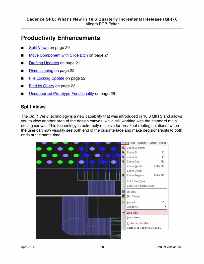
Split Views
The Split View technology is a new capability that was introduced in 16.6 QIR 3 and allows you to view another area of the design canvas, while still working with the standard main editing canvas. This technology is extremely effective for breakout routing solutions, where the user can now visually see both end of the bus/interface and make decisions/edits to both ends at the same time.
April 2014 20 Product Version 16.6

Cadence SPB: What's New in 16.6 Quarterly Incremental Release (QIR) 6Allegro PCB Editor
Move Component with Slide Etch
The Move command has been enhanced to support a new Slide Etch option. When moving components with attached routes, the desire is to maintain the segments on octalinear angles. Prior to this release, the Stretch Etch option was the common method for moving routed components. However, the results were not desirable and required manual edits to restored the intent.
Drafting Updates
Two new commands have been added to the suite of drafting commands introduced over the 16.6 QIR releases:
Extend Segments
This command allows users to extend line and arc segments to a projected intersection point. When invoked from the menu, the user is prompted to Select object to extend. After an object is selected, the user is then prompted to specify another object with which the first object should intersect. Once the second object is selected, the two objects are temporarily extended and highlighted to show the possible intersection points.
Trim Segments
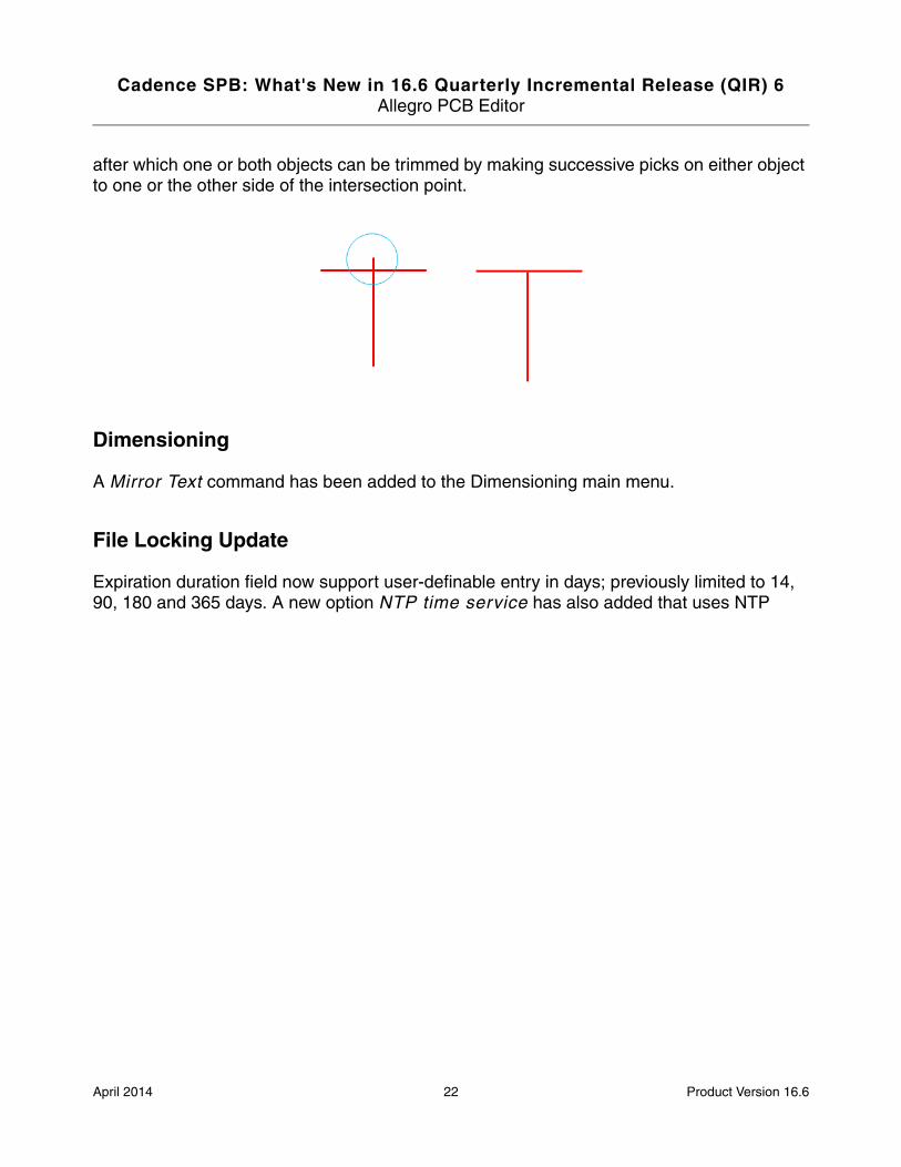
This command allows users to remove portions of line and arc segments that extend beyond specified intersection points. When invoked from the menu, the user is prompted to Select object to trim. After an object is selected, the user is then prompted to select another object intersecting the first. At this point, the user is prompted Select side of segment(s) to trim,
April 2014 21 Product Version 16.6
Cadence SPB: What's New in 16.6 Quarterly Incremental Release (QIR) 6Allegro PCB Editor
after which one or both objects can be trimmed by making successive picks on either object to one or the other side of the intersection point.
Dimensioning
A Mirror Text command has been added to the Dimensioning main menu.
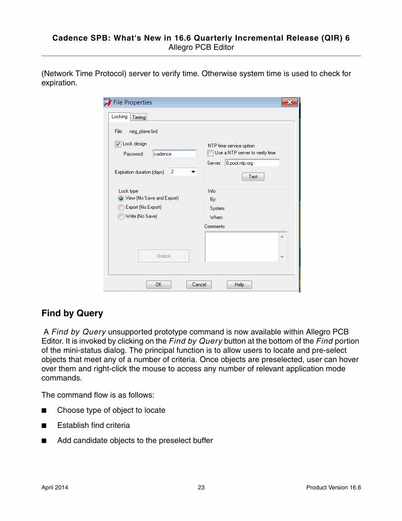
File Locking Update
Expiration duration field now support user-definable entry in days; previously limited to 14, 90, 180 and 365 days. A new option NTP time service has also added that uses NTP
April 2014 22 Product Version 16.6
Cadence SPB: What's New in 16.6 Quarterly Incremental Release (QIR) 6Allegro PCB Editor
(Network Time Protocol) server to verify time. Otherwise system time is used to check for expiration.
Find by Query
A Find by Query unsupported prototype command is now available within Allegro PCB Editor. It is invoked by clicking on the Find by Query button at the bottom of the Find portion of the mini-status dialog. The principal function is to allow users to locate and pre-select objects that meet any of a number of criteria. Once objects are preselected, user can hover over them and right-click the mouse to access any number of relevant application mode commands.
The command flow is as follows:
■ Choose type of object to locate
■ Establish find criteria
■ Add candidate objects to the preselect buffer
April 2014 23 Product Version 16.6

Cadence SPB: What's New in 16.6 Quarterly Incremental Release (QIR) 6Allegro PCB Editor
When first invoked, the dialog appears as follows:
■ The Objects to Find section of the dialog allows users to specify the type of object to locate.
■ These are grouped by type within each tab, and clicking a radio button changes the object type presently under consideration.
■ The Find Criteria section allows users to establish query criteria to filter which object instances make it into the Candidate Objects section.
Examples
The following figure shows an example to find all pins that use padstack PAD19.
April 2014 24 Product Version 16.6

Cadence SPB: What's New in 16.6 Quarterly Incremental Release (QIR) 6Allegro PCB Editor
The following figure shows an example to find/highlight all GND Pins on U100.
Unsupported Prototype Functionality
PCB Editor Users are reminded of functionality that is currently in a prototype state but mature enough for use in production. The suite of commands is available in the Unsupported Prototype menu under the Edit, View, Route and Manufacture menus. Help document access is conveniently located on the last row of the menu.
April 2014 25 Product Version 16.6

Cadence SPB: What's New in 16.6 Quarterly Incremental Release (QIR) 6Allegro PCB Editor
RF PCB Enhancements
In this release, several enhancements have been made in RF PCB to increase productivity.
■ Autoplace Enhancements on page 26
■ Layout Enhancements on page 28
Autoplace Enhancements
■ Support for Placement of Modules
■ Restore Autoplacement Settings
■ Update NET_SHORT Property on Discrete Pins on Netlist Re-import
Support for Placement of Modules
The rf_autoplace and rf_quickplace commands are enhanced to support placement of components in modules.
April 2014 26 Product Version 16.6

Cadence SPB: What's New in 16.6 Quarterly Incremental Release (QIR) 6Allegro PCB Editor
Two new options Include components in modules and Place components in modules are added to commands to include placement of module instances.
For more information, see Module Placement Support for Autoplace in Allegro User Guide: Working with PF PCB.
Restore Autoplacement Settings
You can now save and restore autoplacement settings as an attachment in the current design.
For more information, see Retaining Autoplacement Settings in Allegro User Guide: Working with PF PCB.
April 2014 27 Product Version 16.6

Cadence SPB: What's New in 16.6 Quarterly Incremental Release (QIR) 6Allegro PCB Editor
Update NET_SHORT Property on Discrete Pins on Netlist Re-import
The rf_autoplace command updates the NET_SHORT properties on discrete pins when netlist is re-imported as post processing.
For more information, Handling NET_SHORT property in Allegro User Guide: Working with PF PCB.
Layout Enhancements
To improve the performance of snapping functionalities in large designs, the rf_snap and rf_modify_net commands are enhanced in QIR 6.
As an initiative, two major changes has been made in the following areas:
■ The Snap to pad edge function is enhanced.
■ The cursor dynamics creation time has decreased during interactive snapping and provides better user experience.
April 2014 28 Product Version 16.6

Cadence SPB: What's New in 16.6 Quarterly Incremental Release (QIR) 6Cadence SiP Layout and Allegro Package Designer (APD)
Cadence SiP Layout and Allegro Package Designer (APD)
This section describes the new features and enhancements in Cadence® SiP Layout and Allegro® Package designer (APD) 16.6 QIR 6.
■ New Package Integrity Checks for Wire Bonding on page 30
■ Aligning and Respacing Pins in Symbol Edit Application Mode on page 32
April 2014 29 Product Version 16.6

Cadence SPB: What's New in 16.6 Quarterly Incremental Release (QIR) 6Cadence SiP Layout and Allegro Package Designer (APD)
New Package Integrity Checks for Wire Bonding
Two new rules are now available for wire bonding to check pad wire offset and pin wire count, Pad Bond Wire Offset(F) and Pin Bond Wire Count, respectively.
April 2014 30 Product Version 16.6

Cadence SPB: What's New in 16.6 Quarterly Incremental Release (QIR) 6Cadence SiP Layout and Allegro Package Designer (APD)
■ Pad Wire Bond Offset (F): This rule checks that wires are connected to the center of a pad ensuring proper connectivity during manufacture. The check can also correct any errors, if you select Fix errors automatically (where possible).
■ Pin Bond Wire Count: This rule checks that wire bond pins requiring a specific number of connection have the right number of connections. The rule checks the WIRE_COUNT property of pins to determine the number of connections required. This rule checks only pins with the WIRE_COUNT property set and counts bond wires connecting to objects further down the diestack/substrate.
For more information, see the descriptions in the Package Design Integrity Checks (Tools – Package Design Integrity) window or refer to the APD and SiP: Using the Package Design Integrity Tool section of the Managing the Database chapter in Allegro User Guide: Getting Started with Physical Design.
April 2014 31 Product Version 16.6
Cadence SPB: What's New in 16.6 Quarterly Incremental Release (QIR) 6Cadence SiP Layout and Allegro Package Designer (APD)
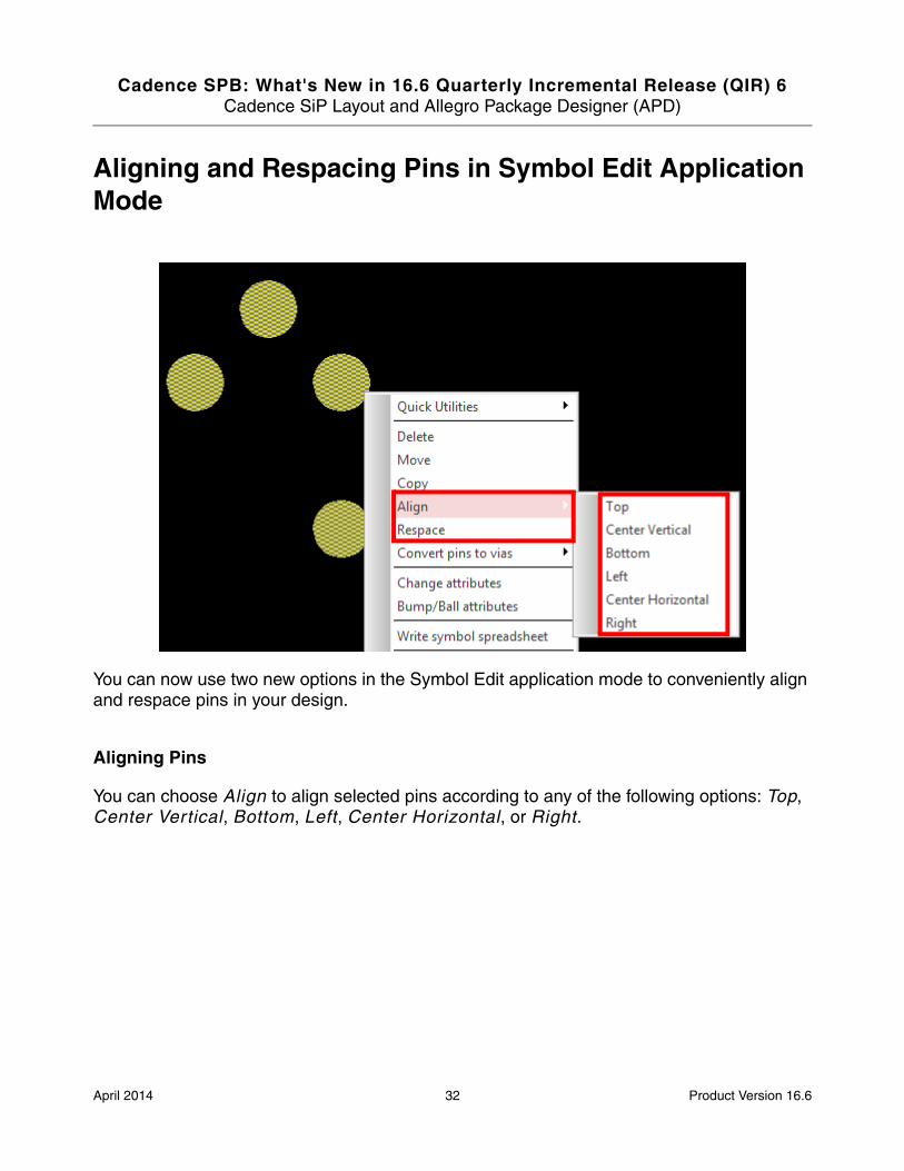
Aligning and Respacing Pins in Symbol Edit Application Mode
You can now use two new options in the Symbol Edit application mode to conveniently align and respace pins in your design.
Aligning Pins
You can choose Align to align selected pins according to any of the following options: Top, Center Vertical, Bottom, Left, Center Horizontal, or Right.
April 2014 32 Product Version 16.6
Cadence SPB: What's New in 16.6 Quarterly Incremental Release (QIR) 6Cadence SiP Layout and Allegro Package Designer (APD)
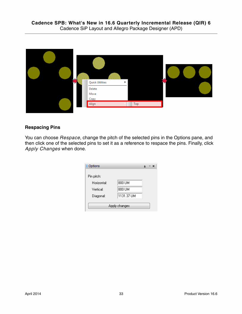
Respacing Pins
You can choose Respace, change the pitch of the selected pins in the Options pane, and then click one of the selected pins to set it as a reference to respace the pins. Finally, click Apply Changes when done.
April 2014 33 Product Version 16.6

Cadence SPB: What's New in 16.6 Quarterly Incremental Release (QIR) 6Allegro Design Entry HDL
Allegro Design Entry HDL
This section describes the new features and enhancements in Allegro® Design Entry HDL 16.6 QIR 6.
■ Support for Net Renaming
■ Enhancements in Variant Editor
Support for Net Renaming
Renaming nets can be difficult to manage because of the associated constraints and properties. Allegro Design Entry HDL now provides a solution that allows you to rename nets while retaining the associated constraints and properties. For more information, refer to the How do I rename nets? section in Allegro Design Entry HDL User Guide.
Enhancements in Variant Editor
The 16.6 QIR 6 release includes support for new special characters: slash (/) in Variant Name and dot (.) in DNI Value.
April 2014 34 Product Version 16.6
Cadence SPB: What's New in 16.6 Quarterly Incremental Release (QIR) 6Allegro FPGA System Planner
Allegro FPGA System Planner
This section describes the new features and enhancements in Allegro® FPGA System Planner16.6 QIR 6.
■ New Device Support on page 36
■ Project Directory Structure (DE-HDL Environment) on page 37
■ Additional Enhancements on page 38
April 2014 35 Product Version 16.6
Cadence SPB: What's New in 16.6 Quarterly Incremental Release (QIR) 6Allegro FPGA System Planner
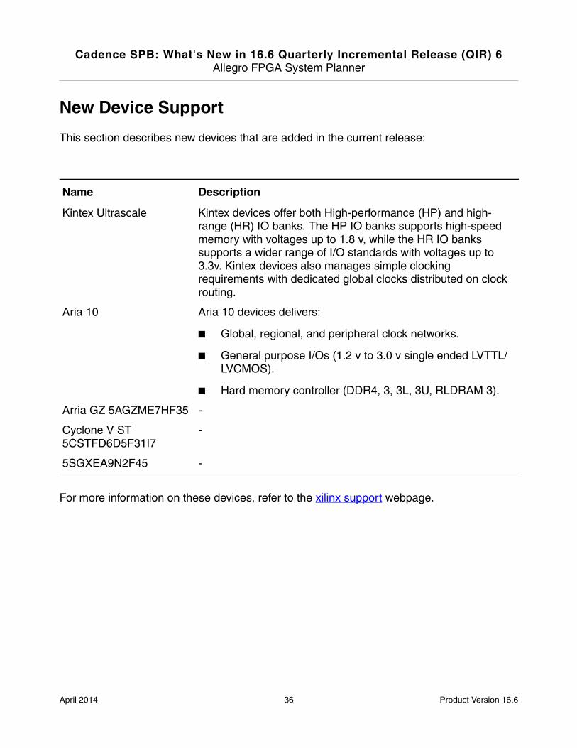
New Device Support
This section describes new devices that are added in the current release:
For more information on these devices, refer to the xilinx support webpage.
Name Description
Kintex Ultrascale Kintex devices offer both High-performance (HP) and high-range (HR) IO banks. The HP IO banks supports high-speed memory with voltages up to 1.8 v, while the HR IO banks supports a wider range of I/O standards with voltages up to 3.3v. Kintex devices also manages simple clocking requirements with dedicated global clocks distributed on clock routing.
Aria 10 Aria 10 devices delivers:
■ Global, regional, and peripheral clock networks.
■ General purpose I/Os (1.2 v to 3.0 v single ended LVTTL/LVCMOS).
■ Hard memory controller (DDR4, 3, 3L, 3U, RLDRAM 3).
Arria GZ 5AGZME7HF35 -
Cyclone V ST 5CSTFD6D5F31I7
-
5SGXEA9N2F45 -
April 2014 36 Product Version 16.6

Cadence SPB: What's New in 16.6 Quarterly Incremental Release (QIR) 6Allegro FPGA System Planner
Project Directory Structure (DE-HDL Environment)
FSP provides an addition option to create a new project. You can now create a new project from an existing project file (.cpm). A new project file (.fsp) is created at the following location <project_name>/<project_name>_lib/<project_name>/fsp.
In addition, a new project directory structure is introduced. When you create a new project for the DE-HDL environment, the following files and directories are created:
■ A project file (<project>.cpm)
This is a DE-HDL project file.
■ A cds.lib file
The cds.lib file contains the DE-HDL symbol libraries which you can use in FSP.
■ fsp_fe_lib
fsp_fe_lib is a local directory and contains DE-HDL symbols generated by FSP.
■ A <project_name>_lib directory
This directory stores the design you capture in FSP in the <project_name> subdirectory, which is referred to as a cell representing the entire design or a part of it.
The cell (<project_name>) contains a set of subdirectories called cell views. By default, fsp is the only cell view present in the cell. It stores the following files and folders
❑ <project_name>.fsp
❑ <project_name>.log
❑ master.tag
❑ lrf
❑ output
When you generate a schematic, all the schematic files are generated in the <project_name> directory.
Note: For detailed information about the files and directories, see the Project Creation and Setup chapter.
April 2014 37 Product Version 16.6

Cadence SPB: What's New in 16.6 Quarterly Incremental Release (QIR) 6Allegro FPGA System Planner
Additional Enhancements
Significant enhancements have been made in the following sections:
■ You can now recover recent changes made in the editors or canvas by using the Undo command. To reverse an undo operation, you use the Redo command immediately after using Undo.
■ The new Canvas Status Bar provides you a quick way to access information about a pin and a net present on the Canvas. For example, when you hover the mouse pointer over a pin, the Canvas Status Bar shows the name of the pin on the left side (Pin:). However if the pin is connected to a net, the net name is displayed on the right side (Net:). You can also hover the mouse pointer over a net to access pin and net information.
■ The Do Not Connect property support is extended to the Virtual Interface component. You can now specify the Do Not Connect property on a Virtual Interface’s pin. A pin with the Do Not Connect property cannot be used for making connection.
■ A new option, Allocate Pair Pins Together is introduced in the Process Option Editor dialog box. Use this option to connect all the single-ended pins of a interface to the available differential pair pins on a device, before connecting differential pair pins to the available differential pair pins.
■ You can now apply fixed internal connection type and fixed external port type on all the pins of FPGA. For detailed information, see the Working with Termination chapter.
■ You can now generate .xdc files and Vivado TCL scripts for all the Virtex 7 devices. An XDC file stores the design constraints and TCL commands generated by FSP. You use both the XDC file and TCL scripts to implement and synthesize the design in the Vivado tool.
April 2014 38 Product Version 16.6

Cadence SPB: What's New in 16.6 Quarterly Incremental Release (QIR) 6OrCAD Capture
OrCAD Capture
This section describes the new features and enhancements in OrCAD® Capture 16.6 QIR 6.
■ PSpice Part Search Symbol Viewer on page 40
■ Enhancements in Learning PSpice on page 41
■ Enhancement: Pin Names and Pin Numbers Behavior on Part Rotation on page 42
■ Enhancement: Specify Pin Spacing in New Part from Spreadsheet using INI Options on page 44
April 2014 39 Product Version 16.6

Cadence SPB: What's New in 16.6 Quarterly Incremental Release (QIR) 6OrCAD Capture
PSpice Part Search Symbol Viewer
Now, you can view the symbol of a part selected in PSpice Part Search before placing the part on the schematic.
If you select any category or library folder in the Category View, symbol of the first part in the folder will be visible in Symbol Viewer.
Note: Only one part can be selected at a time.
April 2014 40 Product Version 16.6
Cadence SPB: What's New in 16.6 Quarterly Incremental Release (QIR) 6OrCAD Capture
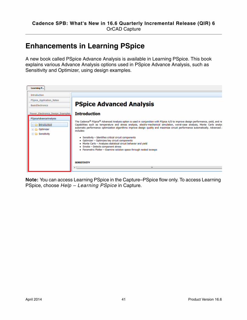
Enhancements in Learning PSpice
A new book called PSpice Advance Analysis is available in Learning PSpice. This book explains various Advance Analysis options used in PSpice Advance Analysis, such as Sensitivity and Optimizer, using design examples.
Note: You can access Learning PSpice in the Capture–PSpice flow only. To access Learning PSpice, choose Help – Learning PSpice in Capture.
April 2014 41 Product Version 16.6
Cadence SPB: What's New in 16.6 Quarterly Incremental Release (QIR) 6OrCAD Capture
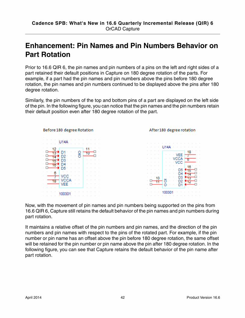
Enhancement: Pin Names and Pin Numbers Behavior on Part Rotation
Prior to 16.6 QIR 6, the pin names and pin numbers of a pins on the left and right sides of a part retained their default positions in Capture on 180 degree rotation of the parts. For example, if a part had the pin names and pin numbers above the pins before 180 degree rotation, the pin names and pin numbers continued to be displayed above the pins after 180 degree rotation.
Similarly, the pin numbers of the top and bottom pins of a part are displayed on the left side of the pin. In the following figure, you can notice that the pin names and the pin numbers retain their default position even after 180 degree rotation of the part.
Now, with the movement of pin names and pin numbers being supported on the pins from 16.6 QIR 6, Capture still retains the default behavior of the pin names and pin numbers during part rotation.
It maintains a relative offset of the pin numbers and pin names, and the direction of the pin numbers and pin names with respect to the pins of the rotated part. For example, if the pin number or pin name has an offset above the pin before 180 degree rotation, the same offset will be retained for the pin number or pin name above the pin after 180 degree rotation. In the following figure, you can see that Capture retains the default behavior of the pin name after part rotation.
April 2014 42 Product Version 16.6

Cadence SPB: What's New in 16.6 Quarterly Incremental Release (QIR) 6OrCAD Capture
Note: If you set the SetOptionString DoNormalRotationForPinNameNumber TCL option to TRUE, the position of the pin name or pin number relative to the pin will not be maintained. For example, if the pin number is placed above a pin and you rotate the symbol by 180 degrees, the pin number will be below the pin after rotation.
April 2014 43 Product Version 16.6

Cadence SPB: What's New in 16.6 Quarterly Incremental Release (QIR) 6OrCAD Capture
Enhancement: Specify Pin Spacing in New Part from Spreadsheet using INI Options
Now, using INI options, you can specify pin to pin spacing; start and end margin space; and the default width and height of the bounding box for a new part from a spreadsheet.
Following are the descriptions of the new INI options, which are set using a TCL command:
■ GeneratePartPin2PinSpace
This INI option specifies pin to pin spacing and can be set using the TCL command. For example, to set pin to pin spacing as 2 grid units, enter SetOptionString "GeneratePartPin2PinSpace" 2 in the Command Window.
■ GeneratePartStartEndMargin
This INI option specifies the start and end margin of the left, right, top, and bottom sides of a part. For example, to set the start margin and end margin as 2 grid units, enter SetOptionString "GeneratePartStartEndMargin" 2 in the Command Window.
April 2014 44 Product Version 16.6

Cadence SPB: What's New in 16.6 Quarterly Incremental Release (QIR) 6OrCAD Capture
■ GeneratePartMinHeight
This INI option specifies the default height of the bounding box of a part. For example, to set the default height of the bounding box of a part as 5 grid units, enter SetOptionString "GeneratePartMinHeight" 5 in the Command Window.
■ GeneratePartMinWidth
This INI option specifies the default width of the bounding box of a part. For example, to set the default width of the bounding box of a part as 5 grid units, enter SetOptionString "GeneratePartMinWidth" 5 in the Command Window.
Note: Use integer multiple of the grid unit to specify the value for these INI options.
April 2014 45 Product Version 16.6

Cadence SPB: What's New in 16.6 Quarterly Incremental Release (QIR) 6Cadence PSpice
Cadence PSpice
This section describes the new features and enhancements in Cadence® PSpice® 16.6 QIR 6.
■ Enhancement in .OPTIONS command on page 47
■ Enhancements in Learning PSpice on page 47
■ PSpice Part Search Symbol Viewer on page 48
April 2014 46 Product Version 16.6
Cadence SPB: What's New in 16.6 Quarterly Incremental Release (QIR) 6Cadence PSpice
Enhancement in .OPTIONS command
In 16.6 QIR 5, three new functions, RND function, RNDR function, and RNDC function, were added in PSpice.
A new option, RNSEED, available with the .OPTIONS command, allows you to set the seed value for the functions added in 16.6 QIR 6. The default seed value is 0.
For example, to specify a seed value of 2, use the following syntax:
.OPTIONS RNDSEED=2
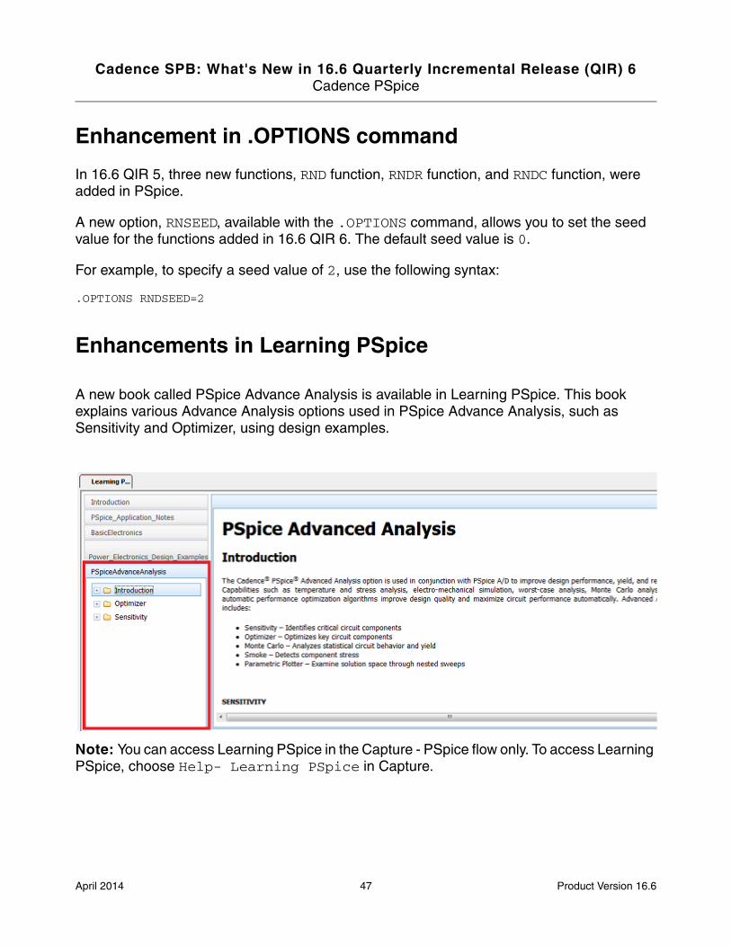
Enhancements in Learning PSpice
A new book called PSpice Advance Analysis is available in Learning PSpice. This book explains various Advance Analysis options used in PSpice Advance Analysis, such as Sensitivity and Optimizer, using design examples.
Note: You can access Learning PSpice in the Capture - PSpice flow only. To access Learning PSpice, choose Help- Learning PSpice in Capture.
April 2014 47 Product Version 16.6

Cadence SPB: What's New in 16.6 Quarterly Incremental Release (QIR) 6Cadence PSpice
PSpice Part Search Symbol Viewer
You can now view the symbol of a part selected in PSpice Part Search before placing the part on the schematic.
The PSpice Part Search can be accessed in the Capture - PSpice flow only. For more information, see PSpice Part Search Symbol Viewer on page 40.
April 2014 48 Product Version 16.6