Embed Size (px)
Citation preview

CAD/CAM at Szczecin shipyard - from drafting to
product model
K. Zytkowski
Stocznia Szczecinska S.A., Design Office, CAD/CAM Department,
9, 77
Abstract
The purpose of this paper is to illustrate the development of a computer aidedship design basing on the experience of Szczecin Shipyard (StoczniaSzczecinska S.A.).
Until the end of the eighties, computer implementations at SzczecinShipyard's design office were mainly limited to theoretical calculations,strength analysis and 2-D graphics that supported a manual drafting. Aboutfive years ago we introduced a new way of thinking about ship design. Ourgoal was to build a virtual ship before a real one - THE PRODUCTINFORMATION MODEL. To carry this idea into effect we had to create anintegrated computer system that would take care of all the aspects of shipdesign and manufacturing. The major part of the system was a Swedishsoftware named Steerbear (now converted to Tribon). At present Tribon andmany other supporting CAD/CAM systems form an integrated computerenvironment designed to create a complete virtual model of the ship.
The presented paper states the main functions of CAD/CAM at SzczecinShipyard, general information about the hardware applied and the prospectsfor the future. The conclusion is an attempt to evaluate the benefits resultingfrom the implementation of CAD/CAM methods at Szczecin Shipyard.
1 Introduction
Conventional design methods based on the design spiral assume that eachdesign stage follows the previous one subsequently and to start a new stage,the previous one must be finished. This method gives best results in a massproduction, where the product is fully defined before it comes to
Transactions on the Built Environment vol 11, © 1995 WIT Press, www.witpress.com, ISSN 1743-3509

248 Marine Technology and Transportation
manufacturing phase. For one piece or small series production all the designand manufacturing activities must be performed more concurrently.
Szczecin Shipyard has always been well known for the wide range of shiptypes designed and produced in small series (3-5 prototypes a year). Since thebeginning of 1990's the ship production lead time has become a key factor forthe shipyard to achieve orders and remain competitive. The need for theincreased productivity and shorter delivery times means that the overlappingof all the design and production activities must increase. "ConcurrentEngineering" (a new key word introduced to describe such situation) became achallenge for our shipyard.
2 Development of CAD/CAM methods at Szczecin Shipyard
Ever since the computers have been introduced to the industry, the SzczecinShipyard tries to use them as the design and manufacturing support. The firstimplementations of computer systems (back in the 1960's and 70's) coveredmainly naval architecture calculations and hull geometry modelling. The firstgraphical application used for the numerical control of steel plate cuttingmachines was introduced in 1972. This application, named "ASTER"(changed and improved throughout the years) was used as a main CAM systemuntil 1991. The first computer aided documentation (classification andworkshop) was produced in 1982 by the use of "AutoCAD" on a PC. Thepossibility of using a PC as a cost effective graphical device seemed to definea future path for the computer aided design and manufacturing. With the useof PC-based CAD systems the drawings could be freely copied from oneproject to another, the changes could be handled more easily. To minimise thelabour consumption in a drafting process, the software vendors and the userscreated libraries of 2-D graphical primitives (symbols) to be used by thedesigners instead of repeating the same activities over and over.
With all the advantages of a PC based CAD systems, it suddenly turned outthat the simple exchange of a drawing board into a computer with a 2-D oreven 3-D graphical system does not allow to modernise the information flowand the production process in the company. Computerising the existingmanual routines does not give as much benefit as taking the opportunity tostreamline the information flow to adapt the company to the new tools andmethods available. The product model concept was introduced to enable thecompany get the best from the computerisation of a design and productionstages.
3 The product model concept
The product model implementation at Szczecin Shipyard has become possiblesince 1991, after purchasing a CAD/CAM system named "Steerbear" (recentlyconverted to a new system - "Tribon") developed by a Swedish companyKockums Computer Systems.
Transactions on the Built Environment vol 11, © 1995 WIT Press, www.witpress.com, ISSN 1743-3509

Marine Technology and Transportation 249
The idea behind a product model is that the information in the model is thebasis for all the design and production activities and contains not only a3D geometry of all the ship components (hull & outfitting), but also thetechnical product definition data necessary to support the complete life cycleof a ship, (marketing - design - manufacturing - operation and maintenance).The data stored in the product model objects is the primary information. Thegraphical model representation, e.g. 2D and (if needed) 3D drawings, partslists and other workshop documentation is the secondary information that isextracted from the model by the CAD/CAM system [Fig. 1].
HULL DESIGN
OUTFITTINGDESIGN
T
JPRODUCTION[TECHNOLOGY
LINKS TO OTHER SYSTEMS
VISUALISATION(DRAWINGS)
PARTSLISTS
N.C. POST-PROCESSORS
Figure 1: Product information model of a ship.
4 Workshop Documentation
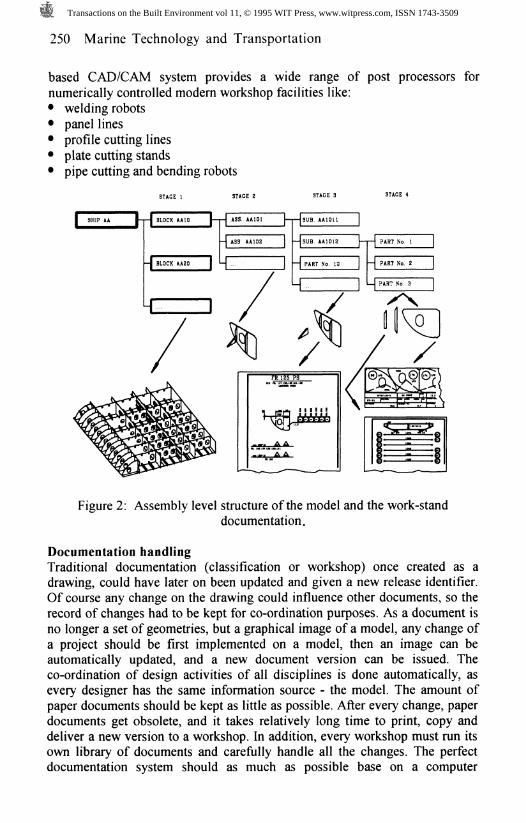
Documentation layoutThe layout of the documentation based on the product model depends on theusers' needs. The documentation can even look exactly as the one created withthe traditional, "manual" routines, but the product model gives the opportunityto change it. Thanks to all the production information included in the model(mainly the structure of assembly levels) it is now possible to create theseparate documents for each stage of manufacture [Fig. 2]. The work-standdocumentation created as an extract from a model can illustrate only the partsand assemblies intended for that particular stand. This can easily be doneusing an assembly level filter both for the drawings and the parts lists. Thegraphical images of the ship (views & sections) can be presented in a way thatreflects a production technology of the particular assembly unit (e.g. upsidedown).Scope of CAD/CAM documentationApart from the construction drawings accompanied by other productioninformation like bending templates, jig diagrams, etc., the product model
Transactions on the Built Environment vol 11, © 1995 WIT Press, www.witpress.com, ISSN 1743-3509
250 Marine Technology and Transportation
based CAD/CAM system provides a wide range of post processors fornumerically controlled modern workshop facilities like:• welding robots• panel lines• profile cutting lines• plate cutting stands• pipe cutting and bending robots
STAGE 1 STAGE 2
1 BLOCK AA10 |—
1 BLOCK AA20 |
1 1
-1 ASS AA101 1 I I
-| ASS AA1D2 j — |
k- I H
4
STAGE 3
SUB. AA1011 |
SUB. AA1012 |— j— |
PART No. 10 1 — |
1 H
V
STAGE 4
PART No. 1
PART No. 2
PART No. 3
XXA (1 <
Figure 2: Assembly level structure of the model and the work-standdocumentation.
Documentation handlingTraditional documentation (classification or workshop) once created as adrawing, could have later on been updated and given a new release identifier.Of course any change on the drawing could influence other documents, so therecord of changes had to be kept for co-ordination purposes. As a document isno longer a set of geometries, but a graphical image of a model, any change ofa project should be first implemented on a model, then an image can beautomatically updated, and a new document version can be issued. Theco-ordination of design activities of all disciplines is done automatically, asevery designer has the same information source - the model. The amount ofpaper documents should be kept as little as possible. After every change, paperdocuments get obsolete, and it takes relatively long time to print, copy anddeliver a new version to a workshop. In addition, every workshop must run itsown library of documents and carefully handle all the changes. The perfectdocumentation system should as much as possible base on a computer
Transactions on the Built Environment vol 11, © 1995 WIT Press, www.witpress.com, ISSN 1743-3509
Marine Technology and Transportation 251
visualisation of drawings, part lists, technological instructions, etc. with adirect access to databases from the workshop.
5 Implementation problems
The implementation process of an integrated CAD/CAM system takes a lot ofexpenditure of work, time and eventually - money. The implementation isusually performed in parallel with executing a busy production plan of ashipyard. To train all the designers in a relatively short period could mean acatastrophe to a yard devoid of the maintenance of the design office. Thegolden mean in such case could be a step-by-step implementation of thesystem modules:• Basic design• Hull• Piping• Accommodation• Cable* etc.or the implementation in two steps:• Basic design (at least lines fairing) & Hull• OutfittingThe last-mentioned method (applied at Szczecin Shipyard) proved to be themost effective, and the interval between the first and the second step should beabout 1 year. Before the outfitting modules of the system are implemented, thehull department should be capable of modelling a major part of a hull structureas early in the design period as possible.
Design work with a product model as a source and a target of theinformation stream naturaly leads to teamwork system. For the design officeswith a traditional organisation (i.e. with a strict division of labour betweendepartments) concurent engineering would mean some changes in theorganisation chart.
The implementation of an integrated system must obtain a high prioritylevel at the top management of the shipyard. The management must alo beaware of the negative consequences of that process like:• costly hardware and software against a long term effect of its
implementation• unpredictable hardware costs depending on a new software, requiring more
and more computational power.
6 Hardware used at Szczecin Shipyard
Looking just a few years back, most CAD systems were available just for asingle hardware platform and operating system. Recently the software vendorslet the users choose a platform that is the most suitable in their environment.The product model based CAD/CAM system is just a part of an integratedsoftware covering other systems like material handling, planing, work
Transactions on the Built Environment vol 11, © 1995 WIT Press, www.witpress.com, ISSN 1743-3509
252 Marine Technology and Transportation
reporting, finance etc. Usually (and that is also the case at Szczecin Shipyard)those systems come from different vendors and operate in different computerenvironments. The important issue is to create interface between those systemsand hardware platforms and achieve the "transparent" links between them.
When the first Steerbear installation was performed at Szczecin Shipyardin 1991, the system could only work on VAX computers using the VMSoperating system. Now, after migration to a Tribon system we can select anyfrom the supported platforms:• Hewlett Packard 9000/700 series workstations using the HP-UX operating
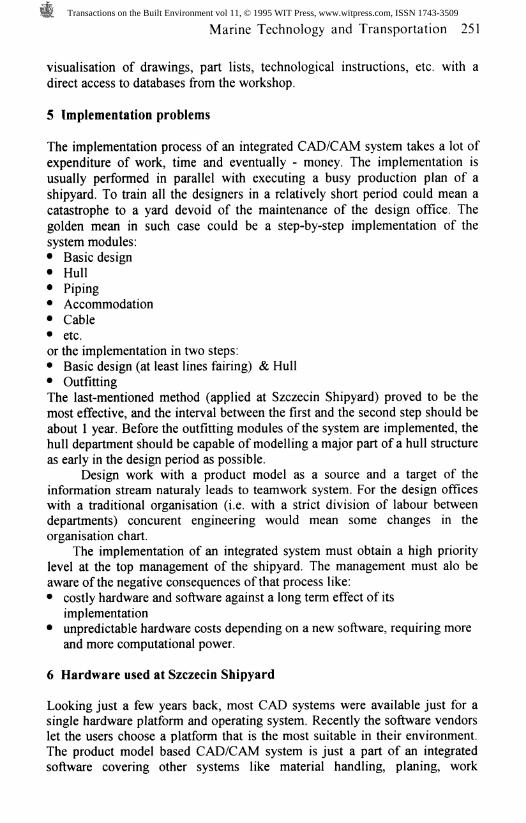
system• Digital Alpha workstations using the Open VMS operating system• Digital VAX workstations using the Open VMS operating system• IBM RS6000 using the AIX operating system• other UNIX platforms have been announced.The user interface in every case is X-window MOTIF so a user changing aworkstation type would not notice any difference in a manner of working.Our present hardware configuration bases on a modern client serverarchitecture with a powerful main server VAX7000 clustered with 4 otherVAX servers and over 30 VAX4000 workstations. We have also connectedover 40 high performance X-terminals [Fig. 3]. In our nearest investment planswe have included the Digital Alpha workstations and more X-terminals. Theuse of X-terminals in our environment proved to be a cost-effective way ofincreasing the amount of graphical devices, and with a powerful server wehave achieved a superb performance of the CAD applications. X-terminals arealso system independent and therefore easy to configurate with any type ofserver.
HARDWARE CON! IRAJIONAT SZCZECIN SHIPYARDDESIGN OFFICE
Figure 3: Hardware configuration at Szczecin Shipyard Design Office.
Transactions on the Built Environment vol 11, © 1995 WIT Press, www.witpress.com, ISSN 1743-3509
Marine Technology and Transportation 253
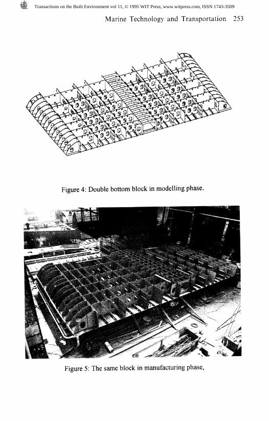
Figure 4: Double bottom block in modelling phase.
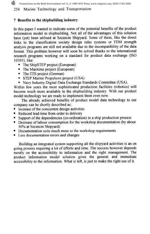
Figure 5: The same block in manufacturing phase.
Transactions on the Built Environment vol 11, © 1995 WIT Press, www.witpress.com, ISSN 1743-3509
254 Marine Technology and Transportation
7 Benefits to the shipbuilding industry
In this paper I wanted to indicate some of the potential benefits of the productinformation model in shipbuilding. Not all of the advantages of this solutionhave (yet) been utilised at Szczecin Shipyard. Some of them, like the directlinks to the classification society design rules systems or FEM strengthanalysis programs are still not available due to the incompatibility of the dataformat. This problem however will soon be solved thanks to the internationalresearch programs working on a standard for product data exchange (ISO10303), like:+ The ShipSTEP project (European)+ The Maritime project (European)+ The ITIS project (German)+ STEP Marine Propulsors project (USA)+ Navy Industry Digital Data Exchange Standards Committee (USA).
Within few years the most sophisticated production facilities (robotics) willbecome much more available in the shipbuilding industry. With our productmodel technology we are ready to implement them even now.
The already achieved benefits of product model data technology to ourcompany can be shortly described as:• Increase of the concurrent design activities• Reduced lead time from order to delivery• Support of the dependencies (co-ordination) in a ship production process• Decrease of labour consumption for the workshop documentation (by about
30% at Szczecin Shipyard)• Documentation suits much more to the workshop requirements• Less documentation errors and changes
Building an integrated system supporting all the shipyard activities is an ongoing process requiring a lot of efforts and time. The success however dependsmostly on the accessibility to information and the right management. Theproduct information model solution gives the general and immediateaccessibility to the information. What is left, is just to make the right use of it.
Transactions on the Built Environment vol 11, © 1995 WIT Press, www.witpress.com, ISSN 1743-3509