Embed Size (px)
Citation preview
Clark County Water Reclamation District July 15, 2015 CAD Standards Manual July 2018
Page 2 of 47
THIS PAGE INTENTIONALLY LEFT BLANK
Clark County Water Reclamation District July 15, 2015 CAD Standards Manual July 2018
Page 3 of 47
Part 1 - General ...................................................................................................................... 5
1.1 Introduction ................................................................................................................. 5
1.2 CAD Project Quality Assurance / Quality Control ........................................................ 5
1.3 Downloading and Installing Support Files .................................................................... 6
Part 2 - General Requirements ............................................................................................... 7
2.1 Software Requirements ............................................................................................... 7
Part 3 - File Format ................................................................................................................. 9
3.1 Drawing Template ....................................................................................................... 9
3.2 CAD Drawings ............................................................................................................ 9
3.3 Plot Guidelines ............................................................................................................ 9
Part 4 - File Naming Conventions ..........................................................................................11
4.1 Production Drawings ................................................................................................. 11
4.2 Reference Files ......................................................................................................... 12
Part 5 - Structure ...................................................................................................................15
5.1 Project Structure ....................................................................................................... 15
5.2 Folder Structure ........................................................................................................ 15
5.3 Sheet Set Manager ................................................................................................... 17
5.4 Sheet Structure ......................................................................................................... 17
5.5 Model Space and Paper Space ................................................................................. 18
5.6 Reference Files ......................................................................................................... 18
5.7 Production Drawings: ................................................................................................ 19
5.8 Viewports .................................................................................................................. 19
5.9 Drawing Annotation ................................................................................................... 19
5.10 Drawing Naming ....................................................................................................... 20
5.11 Title Block ................................................................................................................. 20
5.12 Scales and North Arrow ............................................................................................ 20
Part 6 - Drawing Setup ..........................................................................................................22
6.1 Annotation ................................................................................................................. 22
6.2 Object Linetypes ....................................................................................................... 25
6.3 Symbology ................................................................................................................ 26
6.4 Abbreviations ............................................................................................................ 26
Part 7 - Drawing Layers .........................................................................................................28
7.1 Layer Naming ............................................................................................................ 28
Clark County Water Reclamation District July 15, 2015 CAD Standards Manual July 2018
Page 4 of 47
7.2 Defpoints ................................................................................................................... 30
7.3 Civil Objects .............................................................................................................. 30
Part 8 - Architectural, Structural, Mechanical and Electrical Standards ..................................32
Part 9 - Submittal Requirements ............................................................................................34
9.1 Submittal Requirements ............................................................................................ 34
9.2 Electronic Files .......................................................................................................... 34
9.3 GIS Data Management (Under Development) ........................................................... 35
9.4 Reproduction ............................................................................................................. 35
Appendix A - Symbology ...........................................................................................................36
Appendix B - Abbreviations .......................................................................................................40
Appendix C – Facility Codes .....................................................................................................46
Clark County Water Reclamation District July 15, 2015 CAD Standards Manual July 2018
Page 5 of 47
PART 1 - GENERAL
1.1 INTRODUCTION
This manual is a guide for consultants performing, or desiring to perform, engineering design and/or drafting services for the Clark County Water Reclamation District (District). Guidelines and examples presented in this manual will help consultants produce drawings that are consistent with the District’s format, appearance, and professional standard. These standards are to be implemented in accordance with the requirements of the contract.
The purpose of this manual is to standardize drawing information and improve electronic data sharing between disciplines at the District and from consultants working for the District. It should not be considered a substitute for good communication between the team members involved. Effective communication between the consultant’s staff and the District’s engineering Project Manager, Project Engineer, and the CAD support staff, will help ensure production of concise, accurate and complete drawings – on schedule.
It is recognized that some work performed for the District may need to be submitted to other governmental agencies. Those submittals will need to conform to the reviewing agencies’ standards. However, all submittals to the District must comply with this manual unless District staff grants an exemption.
1.2 CAD PROJECT QUALITY ASSURANCE / QUALITY CONTROL
As a long-term owner of public property, the District will utilize project documents for long-term operations and maintenance of the facility and as a starting point for future projects. As a result, the District expects a high level of accuracy in the prepared documents with a robust Quality Assurance / Quality Control (QA/QC) process used to ensure product quality.
At this time, the District expects to utilize 2D CAD drawing formats for procurement of construction services until the industry is better able to utilize Building Information Model (BIM) formats. Therefore, all drawings generated utilizing BIM technologies must also be thoroughly checked using a reliable QA/QC process prior to delivering 2D CAD drawings and associated models to the District.
A. CAD Projects Quality Assurance
Thoroughly check all drawings using a reliable QA/QC process prior to delivering them to the District. The drawings are typically checked to verify geometric accuracy such that all curves are tangent, elements are drawn on proper layers and on the correct coordinate system, and that additional requirements covered in this manual are met.
The Consultant shall provide sample electronic drawings to the District at various stages in the design process. Milestones for CAD file QA review by the District include:
1. Once the first drawing is set up that represents how all the drawings will be provided, the Consultant shall send the sample drawing (CAD file) to the District Project Engineer. This will allow the District to provide feedback at the start of the project to establish that this design guide is being followed.
2. At 30% Design Development, and at each subsequent submittal prior to the bid stage, the Consultant shall submit sample electronic drawings from each discipline, and from each sub-consultant, to the District Project Engineer to ensure that all CAD and reprographic standards are being met.
Clark County Water Reclamation District July 15, 2015 CAD Standards Manual July 2018
Page 6 of 47
B. BIM Projects Quality Assurance
Modeling in three dimensions (3D) is not required. However, the District recognizes the value of these models and intends to implement procedures for 3D modeling of District projects at a future date.
1.3 DOWNLOADING AND INSTALLING SUPPORT FILES
A. The District standard design CAD drawings are available on the District website at www.cleanwaterteam.com/engineering.html.
Clark County Water Reclamation District July 15, 2015 CAD Standards Manual July 2018
Page 7 of 47
PART 2 - GENERAL REQUIREMENTS
2.1 SOFTWARE REQUIREMENTS
All production design drawings must be completed using Autodesk software and of a version within 2 years of the most recent release at the signing of the contract. Any files converted from previous versions of AutoCAD, or from other formats, shall conform to the current District CAD Standards as outlined in this Manual.
A. Drawing Setup
1. The District utilizes the drawing setups outlined in this Manual for all CAD projects. The District will not accept drawings with alternate symbols, text height, font style, layer names and settings, or other deviations from the standards described herein without prior approval from the District Project Manager.
2. Full size production drawings shall be 22”x34” (ANSI D). Half size drawings shall be produced at exactly one-half scale of the full size drawings, to 11”x17” (ANSI B).
3. Unless otherwise approved by the District Project Manager, drawing title blocks shall be located along the right edge of each drawing.
4. The North arrow shall point up or to the left. The District Project Manager must approve any deviation.
5. All text is to be oriented to be read from the bottom and right, unless otherwise approved by the District Project Manager.
6. Alignment stationing direction shall run from left to right on production drawings, unless otherwise approved by the District Project Manager.
7. Drawing unit insertion scale shall be set to either “Unitless” or “U.S. Survey Feet”.
8. UCS shall be set to “World”.
9. The District allows the use of multiple layout tabs for Production Drawings. However, it is up to the consultant to provide files of a reasonable size. It is recommended that each file is limited to approximately ten (10) tabs within a single file. Files must use the maximum reasonable number of tabs to avoid an unnecessary number of separate files.

Clark County Water Reclamation District July 15, 2015 CAD Standards Manual July 2018
Page 8 of 47
THIS PAGE INTENTIONALLY LEFT BLANK
Clark County Water Reclamation District July 15, 2015 CAD Standards Manual July 2018
Page 9 of 47
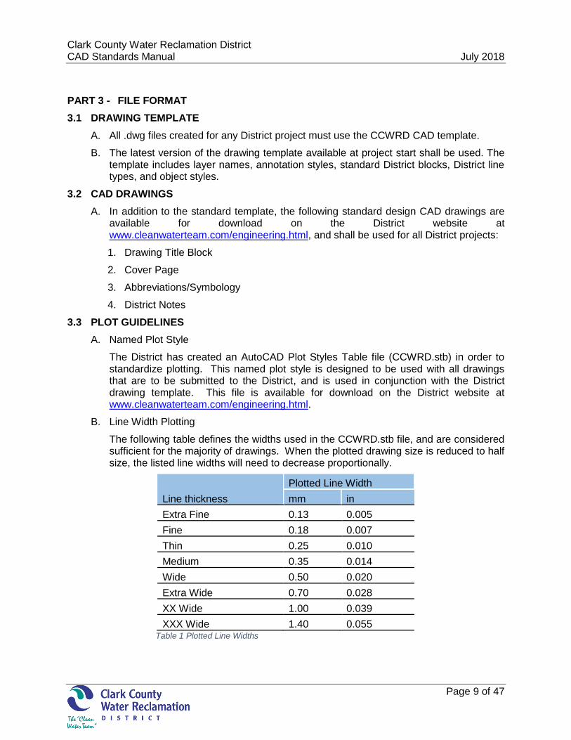
PART 3 - FILE FORMAT
3.1 DRAWING TEMPLATE
A. All .dwg files created for any District project must use the CCWRD CAD template.
B. The latest version of the drawing template available at project start shall be used. The template includes layer names, annotation styles, standard District blocks, District line types, and object styles.
3.2 CAD DRAWINGS
A. In addition to the standard template, the following standard design CAD drawings are available for download on the District website at www.cleanwaterteam.com/engineering.html, and shall be used for all District projects:
1. Drawing Title Block
2. Cover Page
3. Abbreviations/Symbology
4. District Notes
3.3 PLOT GUIDELINES
A. Named Plot Style
The District has created an AutoCAD Plot Styles Table file (CCWRD.stb) in order to standardize plotting. This named plot style is designed to be used with all drawings that are to be submitted to the District, and is used in conjunction with the District drawing template. This file is available for download on the District website at www.cleanwaterteam.com/engineering.html.
B. Line Width Plotting
The following table defines the widths used in the CCWRD.stb file, and are considered sufficient for the majority of drawings. When the plotted drawing size is reduced to half size, the listed line widths will need to decrease proportionally.
Line thickness
Plotted Line Width
mm in
Extra Fine 0.13 0.005
Fine 0.18 0.007
Thin 0.25 0.010
Medium 0.35 0.014
Wide 0.50 0.020
Extra Wide 0.70 0.028
XX Wide 1.00 0.039
XXX Wide 1.40 0.055 Table 1 Plotted Line Widths
Clark County Water Reclamation District July 15, 2015 CAD Standards Manual July 2018
Page 10 of 47
THIS PAGE INTENTIONALLY LEFT BLANK
Clark County Water Reclamation District July 15, 2015 CAD Standards Manual July 2018
Page 11 of 47
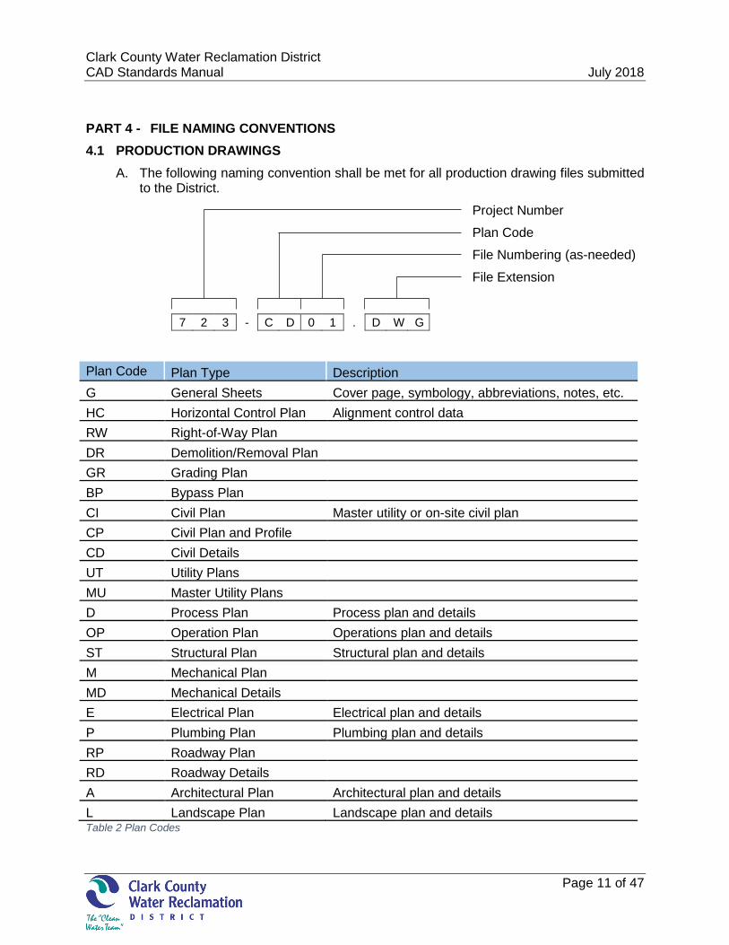
PART 4 - FILE NAMING CONVENTIONS
4.1 PRODUCTION DRAWINGS
A. The following naming convention shall be met for all production drawing files submitted to the District.
Project Number
Plan Code
File Numbering (as-needed)
File Extension
7 2 3 - C D 0 1 . D W G
Plan Code Plan Type Description
G General Sheets Cover page, symbology, abbreviations, notes, etc.
HC Horizontal Control Plan Alignment control data
RW Right-of-Way Plan DR Demolition/Removal Plan GR Grading Plan
BP Bypass Plan
CI Civil Plan Master utility or on-site civil plan
CP Civil Plan and Profile
CD Civil Details
UT Utility Plans
MU Master Utility Plans
D Process Plan Process plan and details
OP Operation Plan Operations plan and details
ST Structural Plan Structural plan and details
M Mechanical Plan
MD Mechanical Details
E Electrical Plan Electrical plan and details
P Plumbing Plan Plumbing plan and details
RP Roadway Plan
RD Roadway Details
A Architectural Plan Architectural plan and details
L Landscape Plan Landscape plan and details Table 2 Plan Codes
Clark County Water Reclamation District July 15, 2015 CAD Standards Manual July 2018
Page 12 of 47
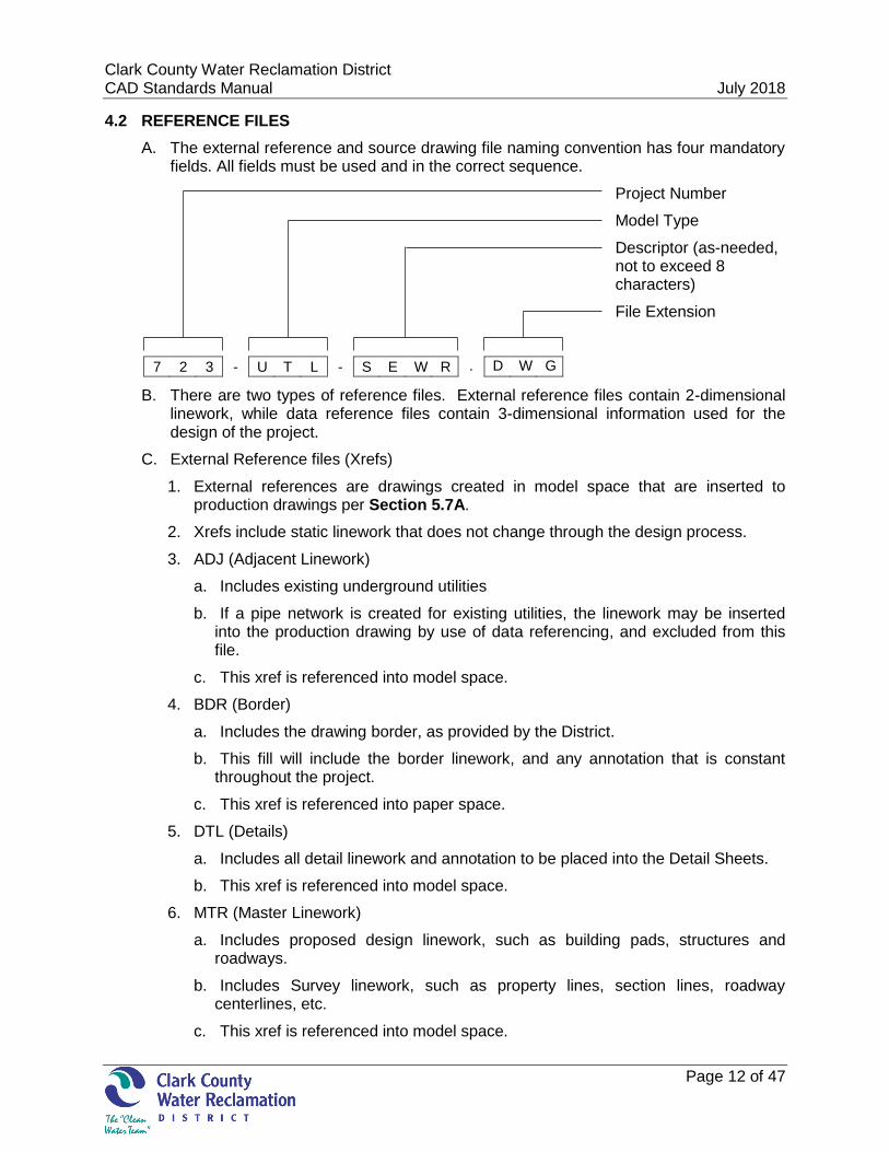
4.2 REFERENCE FILES
A. The external reference and source drawing file naming convention has four mandatory fields. All fields must be used and in the correct sequence.
Project Number
Model Type
Descriptor (as-needed, not to exceed 8 characters)
File Extension
7 2 3 - U T L - S E W R . D W G
B. There are two types of reference files. External reference files contain 2-dimensional linework, while data reference files contain 3-dimensional information used for the design of the project.
C. External Reference files (Xrefs)
1. External references are drawings created in model space that are inserted to production drawings per Section 5.7A.
2. Xrefs include static linework that does not change through the design process.
3. ADJ (Adjacent Linework)
a. Includes existing underground utilities
b. If a pipe network is created for existing utilities, the linework may be inserted into the production drawing by use of data referencing, and excluded from this file.
c. This xref is referenced into model space.
4. BDR (Border)
a. Includes the drawing border, as provided by the District.
b. This fill will include the border linework, and any annotation that is constant throughout the project.
c. This xref is referenced into paper space.
5. DTL (Details)
a. Includes all detail linework and annotation to be placed into the Detail Sheets.
b. This xref is referenced into model space.
6. MTR (Master Linework)
a. Includes proposed design linework, such as building pads, structures and roadways.
b. Includes Survey linework, such as property lines, section lines, roadway centerlines, etc.
c. This xref is referenced into model space.
Clark County Water Reclamation District July 15, 2015 CAD Standards Manual July 2018
Page 13 of 47
7. TOP (Existing Topographic Linework)
a. This will include any aboveground existing feature 2-dimensional linework, such as buildings, roadways, fire hydrants, and any other visible features.
b. Surface contours are created in the GRD data reference file. As such, they are displayed as a civil object, and are not included in this file.
c. This xref is referenced into model space.
Model Type (Xrefs) Description
ADJ Adjacent underground linework
BDR Drawing title and border
DTL Details
MTR Master linework
TOP Existing topographic features Table 3 External Reference Naming
D. Data Reference files (Drefs)
1. These are the files where the project design is performed. Data references are created from the design objects created in model space within these files. The data references are then inserted into the production drawing by use of the “Toolspace Data Shortcuts”.
2. Drefs include objects that are needed for design purposes, or are expected to change throughout the design process.
3. ALN (Alignments)
a. This will include all alignments where design is required.
b. Proposed pipe and roadway alignments belong in this file.
c. If existing alignments will be used for labelling purposes, the alignment will be included here as a data reference.
d. Alignments are used to create profile surface linework. The alignment profile data shall be created in this file.
e. The referenced information will include alignments with existing and finished grade profiles.
4. GRD (Surfaces)
a. It is recommended that each surface be created in its own drawing.
b. These reference files will include existing and proposed surfaces.
c. The referenced information will include existing and proposed contours.
d. All design linework, such as breaklines, feature lines, 3D polylines, points, exclusion areas, and boundaries, are required to be included in this file.
e. Contours generated from Terrestrial or Mobile LiDAR data sets shall have the associated .tin file decimated to 10% of the original point acquisition size.
5. UTL (Utilities)
a. Includes all pipe networks, including proposed utilities, and any existing utilities created for design purposes.
Clark County Water Reclamation District July 15, 2015 CAD Standards Manual July 2018
Page 14 of 47
b. Design information will include pipes and structures.
c. A separate UTL file should be created for each proposed and existing utility network.
Model Type (Drefs) Description
ALN Alignments
GRD Existing and proposed surfaces
UTL Pipe networks Table 4 Data Reference Naming
E. Hyperlinks
1. Hyperlinks can be added to objects within CAD, which will allow the user to open relevant records directly from the CAD file. When documents are available, they shall be hyperlinked to the appropriate objects. Documents to be hyperlinked would include utility records, deeds, easements, and any other applicable information. The hyperlink will be set to use a relative path.
Clark County Water Reclamation District July 15, 2015 CAD Standards Manual July 2018
Page 15 of 47
PART 5 - STRUCTURE
5.1 PROJECT STRUCTURE
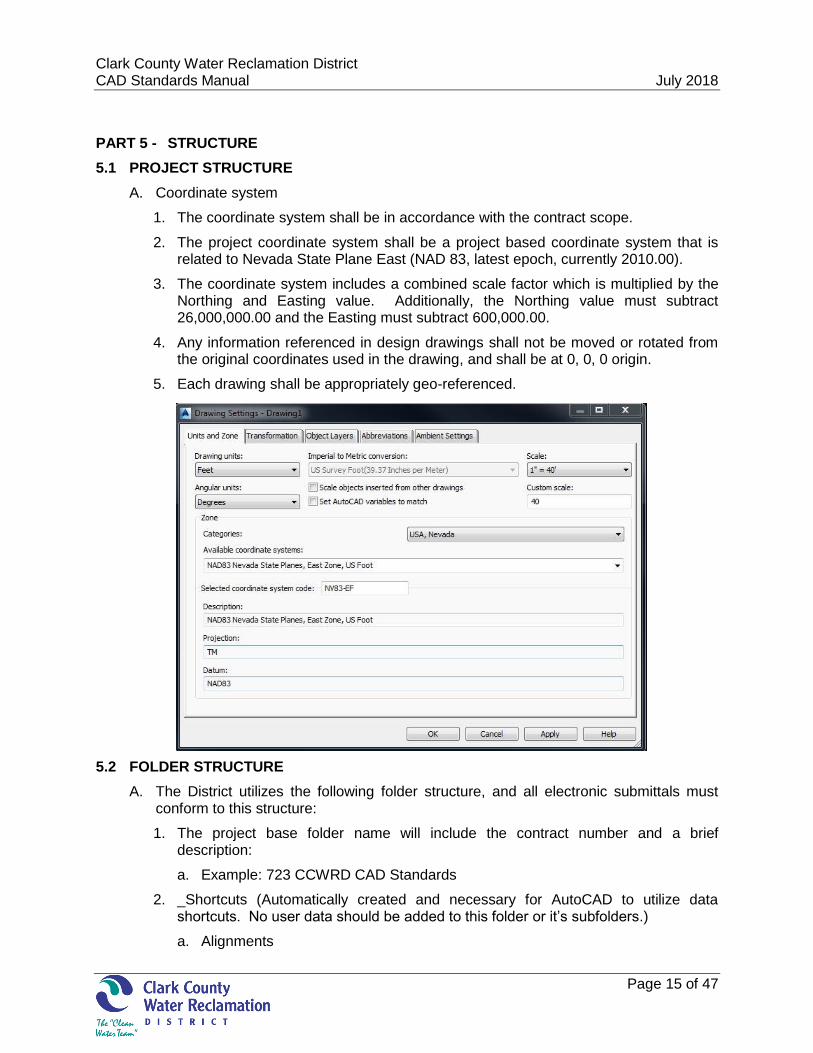
A. Coordinate system
1. The coordinate system shall be in accordance with the contract scope.
2. The project coordinate system shall be a project based coordinate system that is related to Nevada State Plane East (NAD 83, latest epoch, currently 2010.00).
3. The coordinate system includes a combined scale factor which is multiplied by the Northing and Easting value. Additionally, the Northing value must subtract 26,000,000.00 and the Easting must subtract 600,000.00.
4. Any information referenced in design drawings shall not be moved or rotated from the original coordinates used in the drawing, and shall be at 0, 0, 0 origin.
5. Each drawing shall be appropriately geo-referenced.
5.2 FOLDER STRUCTURE
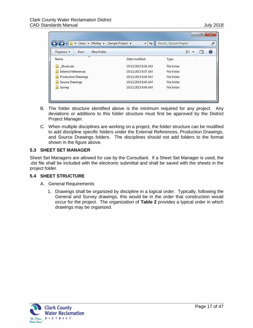
A. The District utilizes the following folder structure, and all electronic submittals must conform to this structure:
1. The project base folder name will include the contract number and a brief description:
a. Example: 723 CCWRD CAD Standards
2. _Shortcuts (Automatically created and necessary for AutoCAD to utilize data shortcuts. No user data should be added to this folder or it’s subfolders.)
a. Alignments
Clark County Water Reclamation District July 15, 2015 CAD Standards Manual July 2018
Page 16 of 47
b. PipeNetworks
c. PressurePipeNetworks
d. Profiles
e. Surfaces
f. ViewFrameGroups
3. External References (Static reference files shall be stored here, such as existing feature files, survey linework files, and 2-dimensionsal files.)
a. DGN
b. DWF
c. DWG
d. Images
4. Production Drawings (Production drawings and the Sheet Set Manager (if used) are to be stored here.)
5. Source Drawings (Drawings utilizing civil objects will be stored here. Data references are created from these files.)
a. Alignments
b. Pipe Networks
c. Surfaces
d. View Frame Groups
6. Survey
a. LiDAR point data, as applicable:
i. Provide in .las and .txt file format with RGB values.
ii. Do not embed in the CAD deliverable due to size constraints.
b. Points
i. Include all points within CAD file.
ii. Include a .csv file in the following order:
a) Pt#, N, E, Elev, Desc
Clark County Water Reclamation District July 15, 2015 CAD Standards Manual July 2018
Page 17 of 47
B. The folder structure identified above is the minimum required for any project. Any deviations or additions to this folder structure must first be approved by the District Project Manager.
C. When multiple disciplines are working on a project, the folder structure can be modified to add discipline specific folders under the External References, Production Drawings, and Source Drawings folders. The disciplines should not add folders to the format shown in the figure above.
5.3 SHEET SET MANAGER
Sheet Set Managers are allowed for use by the Consultant. If a Sheet Set Manager is used, the .dst file shall be included with the electronic submittal and shall be saved with the sheets in the project folder.
5.4 SHEET STRUCTURE
A. General Requirements
1. Drawings shall be organized by discipline in a logical order. Typically, following the General and Survey drawings, this would be in the order that construction would occur for the project. The organization of Table 2 provides a typical order in which drawings may be organized.
Clark County Water Reclamation District July 15, 2015 CAD Standards Manual July 2018
Page 18 of 47
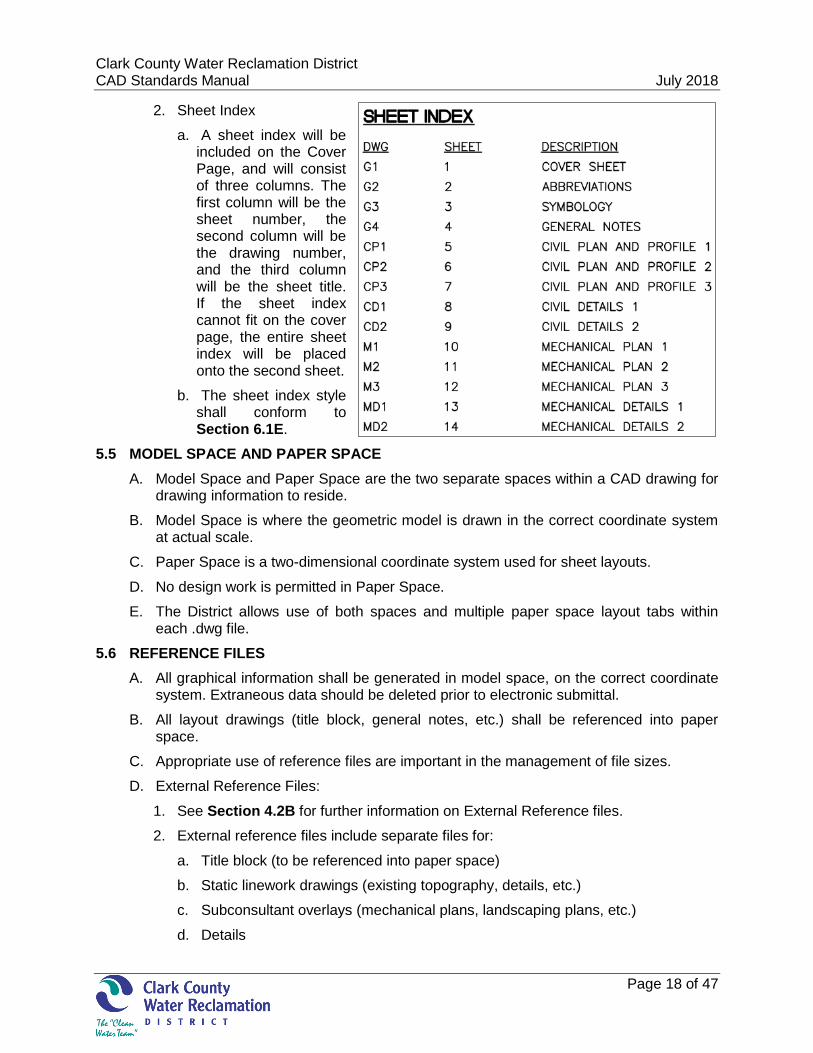
2. Sheet Index
a. A sheet index will be included on the Cover Page, and will consist of three columns. The first column will be the sheet number, the second column will be the drawing number, and the third column will be the sheet title. If the sheet index cannot fit on the cover page, the entire sheet index will be placed onto the second sheet.
b. The sheet index style shall conform to Section 6.1E.
5.5 MODEL SPACE AND PAPER SPACE
A. Model Space and Paper Space are the two separate spaces within a CAD drawing for drawing information to reside.
B. Model Space is where the geometric model is drawn in the correct coordinate system at actual scale.
C. Paper Space is a two-dimensional coordinate system used for sheet layouts.
D. No design work is permitted in Paper Space.
E. The District allows use of both spaces and multiple paper space layout tabs within each .dwg file.
5.6 REFERENCE FILES
A. All graphical information shall be generated in model space, on the correct coordinate system. Extraneous data should be deleted prior to electronic submittal.
B. All layout drawings (title block, general notes, etc.) shall be referenced into paper space.
C. Appropriate use of reference files are important in the management of file sizes.
D. External Reference Files:
1. See Section 4.2B for further information on External Reference files.
2. External reference files include separate files for:
a. Title block (to be referenced into paper space)
b. Static linework drawings (existing topography, details, etc.)
c. Subconsultant overlays (mechanical plans, landscaping plans, etc.)
d. Details
Clark County Water Reclamation District July 15, 2015 CAD Standards Manual July 2018
Page 19 of 47
3. See Section 4.2D for further information on Source Drawings (Data Reference Files):
a. These are design files created through the use of civil objects.
b. Data reference files include separate files for:
i. Alignments
ii. Pipe Networks
iii. Surfaces
5.7 PRODUCTION DRAWINGS:
A. External reference files shall be:
1. Attached by reference type “Overlay”
2. Path Type shall be set to “Relative Path”
3. Scale shall be “1”
4. Insertion point shall be 0, 0, 0
5. Rotation shall be “0”
6. Inserted onto layer ‘0’
B. Source files shall be referenced into the drawing using the “Toolspace Data Shortcuts”.
C. Production drawings shall contain the following (as applicable):
1. North arrow and scale bar
2. Match lines and associated text
3. Annotation, notes, tables, and legends
4. Title block
5. Detail titles
6. Revision clouds, deltas, and notes
7. Key maps (Place in the upper right corner, if possible)
8. Professional Stamps
5.8 VIEWPORTS
A. A viewport is a window in the Paper Space which allows the user to view the Model Space.
B. Viewports should be placed on a non-plottable layer.
5.9 DRAWING ANNOTATION
A. With the implementation of data references and the use of multiple drawing tabs, it is often practical to annotate drawing objects directly within the Production Drawing. Place object dimensions and text within model space.
B. All design and detail objects will be in model space at actual scale, following the layer conventions set forth within this document.
Clark County Water Reclamation District July 15, 2015 CAD Standards Manual July 2018
Page 20 of 47
5.10 DRAWING NAMING
A. Drawing names shall include the Plan Code as identified in Section 4.1A Table 2, followed by sequential numbering, with no hyphen between the Plan Code and drawing number.
5.11 TITLE BLOCK
A. Standardized title block information ensures the uniformity of District drawings, and aids subsequent drawing storage and retrieval efforts. These title blocks shall be used on all District projects. Titles shall consist of the facility name and project title as shown on the project schedule. The project title of the drawings should also be exactly the same as the title on the accompanying specifications. Check with the District Project Manager if there is any doubt about the proper name of the project.
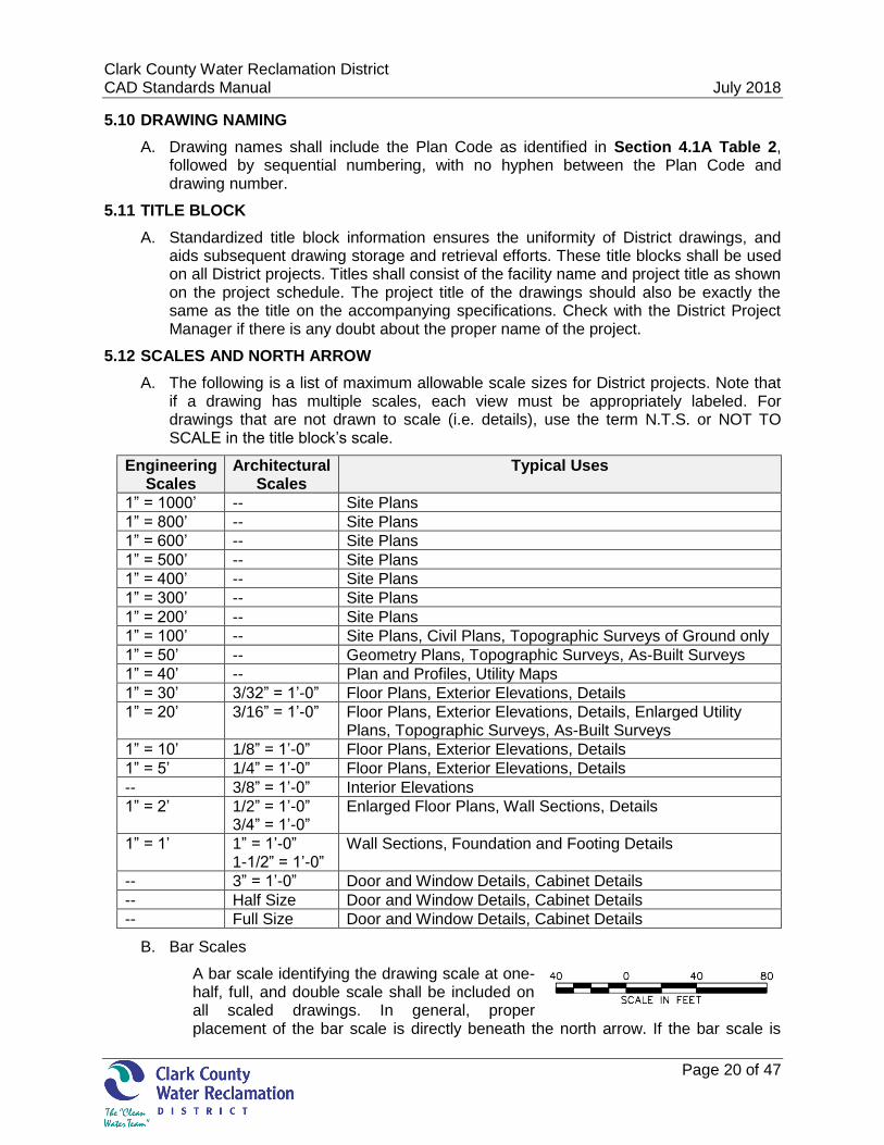
5.12 SCALES AND NORTH ARROW
A. The following is a list of maximum allowable scale sizes for District projects. Note that if a drawing has multiple scales, each view must be appropriately labeled. For drawings that are not drawn to scale (i.e. details), use the term N.T.S. or NOT TO SCALE in the title block’s scale.
Engineering Scales
Architectural Scales
Typical Uses
1” = 1000’ -- Site Plans
1” = 800’ -- Site Plans
1” = 600’ -- Site Plans
1” = 500’ -- Site Plans
1” = 400’ -- Site Plans
1” = 300’ -- Site Plans
1” = 200’ -- Site Plans
1” = 100’ -- Site Plans, Civil Plans, Topographic Surveys of Ground only
1” = 50’ -- Geometry Plans, Topographic Surveys, As-Built Surveys
1” = 40’ -- Plan and Profiles, Utility Maps
1” = 30’ 3/32” = 1’-0” Floor Plans, Exterior Elevations, Details
1” = 20’ 3/16” = 1’-0” Floor Plans, Exterior Elevations, Details, Enlarged Utility Plans, Topographic Surveys, As-Built Surveys
1” = 10’ 1/8” = 1’-0” Floor Plans, Exterior Elevations, Details
1” = 5’ 1/4” = 1’-0” Floor Plans, Exterior Elevations, Details
-- 3/8” = 1’-0” Interior Elevations
1” = 2’ 1/2” = 1’-0” 3/4” = 1’-0”
Enlarged Floor Plans, Wall Sections, Details
1” = 1’ 1” = 1’-0” 1-1/2” = 1’-0”
Wall Sections, Foundation and Footing Details
-- 3” = 1’-0” Door and Window Details, Cabinet Details
-- Half Size Door and Window Details, Cabinet Details
-- Full Size Door and Window Details, Cabinet Details
B. Bar Scales
A bar scale identifying the drawing scale at one-half, full, and double scale shall be included on all scaled drawings. In general, proper placement of the bar scale is directly beneath the north arrow. If the bar scale is
Clark County Water Reclamation District July 15, 2015 CAD Standards Manual July 2018
Page 21 of 47
used when there is no north arrow, or if there are separate horizontal and vertical scales, place the bar scale as close as practical to the detail title.
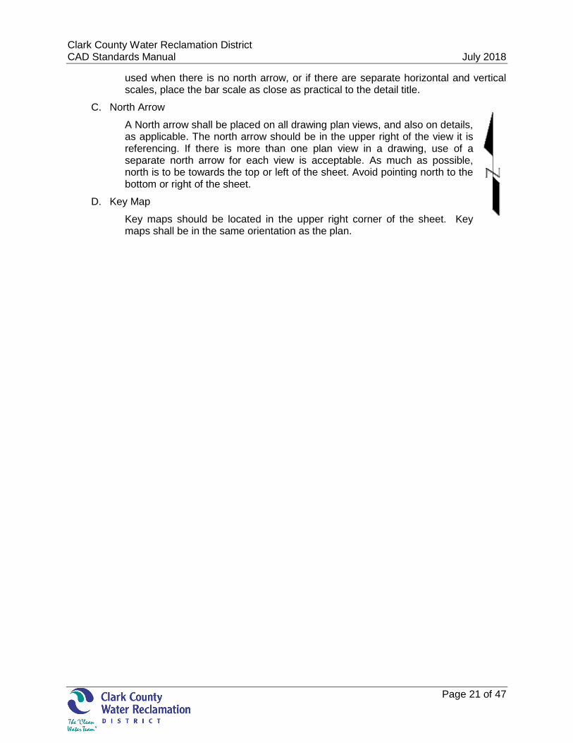
C. North Arrow
A North arrow shall be placed on all drawing plan views, and also on details, as applicable. The north arrow should be in the upper right of the view it is referencing. If there is more than one plan view in a drawing, use of a separate north arrow for each view is acceptable. As much as possible, north is to be towards the top or left of the sheet. Avoid pointing north to the bottom or right of the sheet.
D. Key Map
Key maps should be located in the upper right corner of the sheet. Key maps shall be in the same orientation as the plan.
Clark County Water Reclamation District July 15, 2015 CAD Standards Manual July 2018
Page 22 of 47
PART 6 - DRAWING SETUP
6.1 ANNOTATION
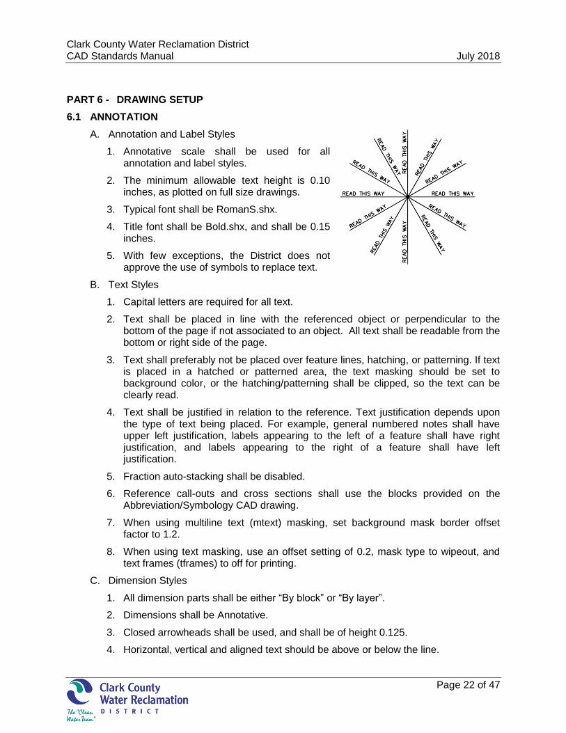
A. Annotation and Label Styles
1. Annotative scale shall be used for all annotation and label styles.
2. The minimum allowable text height is 0.10 inches, as plotted on full size drawings.
3. Typical font shall be RomanS.shx.
4. Title font shall be Bold.shx, and shall be 0.15 inches.
5. With few exceptions, the District does not approve the use of symbols to replace text.
B. Text Styles
1. Capital letters are required for all text.
2. Text shall be placed in line with the referenced object or perpendicular to the bottom of the page if not associated to an object. All text shall be readable from the bottom or right side of the page.
3. Text shall preferably not be placed over feature lines, hatching, or patterning. If text is placed in a hatched or patterned area, the text masking should be set to background color, or the hatching/patterning shall be clipped, so the text can be clearly read.
4. Text shall be justified in relation to the reference. Text justification depends upon the type of text being placed. For example, general numbered notes shall have upper left justification, labels appearing to the left of a feature shall have right justification, and labels appearing to the right of a feature shall have left justification.
5. Fraction auto-stacking shall be disabled.
6. Reference call-outs and cross sections shall use the blocks provided on the Abbreviation/Symbology CAD drawing.
7. When using multiline text (mtext) masking, set background mask border offset factor to 1.2.
8. When using text masking, use an offset setting of 0.2, mask type to wipeout, and text frames (tframes) to off for printing.
C. Dimension Styles
1. All dimension parts shall be either “By block” or “By layer”.
2. Dimensions shall be Annotative.
3. Closed arrowheads shall be used, and shall be of height 0.125.
4. Horizontal, vertical and aligned text should be above or below the line.
Clark County Water Reclamation District July 15, 2015 CAD Standards Manual July 2018
Page 23 of 47
5. If a fill color is used, it should be set to ‘Background’.
6. Dimension lines shall not cross each other, other text, or leader lines. When crossing is unavoidable, insert a break in the dimension line or leader line at the place of crossing.
D. Leader/Multileader Styles
1. The District prefers the use of multileaders for callouts.
2. Multileaders shall be Annotative.
3. The leader arrow head size shall be 0.125”.
4. All leader part colors shall be either “By Block” or “By Layer”.
5. Text shall be attached to “Middle of Top Line”.
6. For multileader styles that use blocks, utilize standard blocks as practicable. Standard blocks should be to a scale of 1.
7. Leaders shall not cross each other, other text, or dimension lines. When crossing is unavoidable, insert a break in the leader line or dimension line at the crossing.
E. Table Styles
1. Table annotation shall conform to Section 6.1B.
F. Notes
1. Notes shall be either numerically or alphabetically ordered.
2. Notes, tables, and legends are typically located along the right side of the drawing area, below the key map.
3. Construction Notes can utilize standard blocks, multileaders or civil object layers (see Section 7.3A). Where practicable, use standard blocks included in the multileader styles.
4. When more than one construction note applies to an object, link the construction note identifiers in sequence and share one leader.
5. When construction notes apply to specific details on the same sheet, the notes should be located near the detail title. When multiple details on the same sheet have construction notes, the numbering shall start with “1” for each detail.
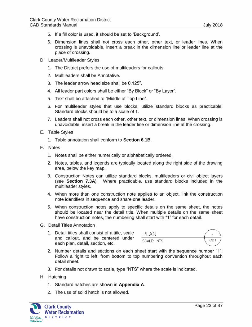
G. Detail Titles Annotation
1. Detail titles shall consist of a title, scale and callout, and be centered under each plan, detail, section, etc.
2. Number details and sections on each sheet start with the sequence number “1”. Follow a right to left, from bottom to top numbering convention throughout each detail sheet.
3. For details not drawn to scale, type “NTS” where the scale is indicated.
H. Hatching
1. Standard hatches are shown in Appendix A.
2. The use of solid hatch is not allowed.
Clark County Water Reclamation District July 15, 2015 CAD Standards Manual July 2018
Page 24 of 47
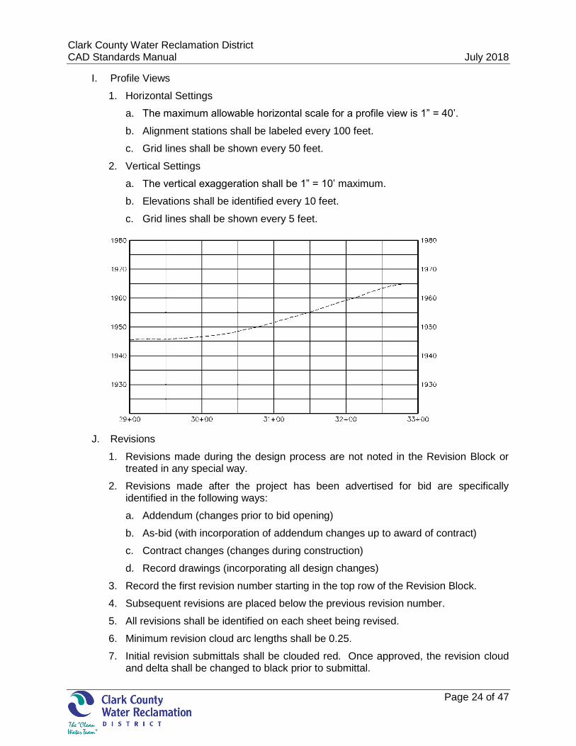
I. Profile Views
1. Horizontal Settings
a. The maximum allowable horizontal scale for a profile view is 1” = 40’.
b. Alignment stations shall be labeled every 100 feet.
c. Grid lines shall be shown every 50 feet.
2. Vertical Settings
a. The vertical exaggeration shall be 1” = 10’ maximum.
b. Elevations shall be identified every 10 feet.
c. Grid lines shall be shown every 5 feet.
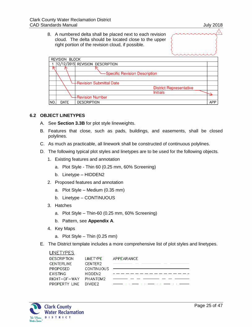
J. Revisions
1. Revisions made during the design process are not noted in the Revision Block or treated in any special way.
2. Revisions made after the project has been advertised for bid are specifically identified in the following ways:
a. Addendum (changes prior to bid opening)
b. As-bid (with incorporation of addendum changes up to award of contract)
c. Contract changes (changes during construction)
d. Record drawings (incorporating all design changes)
3. Record the first revision number starting in the top row of the Revision Block.
4. Subsequent revisions are placed below the previous revision number.
5. All revisions shall be identified on each sheet being revised.
6. Minimum revision cloud arc lengths shall be 0.25.
7. Initial revision submittals shall be clouded red. Once approved, the revision cloud and delta shall be changed to black prior to submittal.
Clark County Water Reclamation District July 15, 2015 CAD Standards Manual July 2018
Page 25 of 47
8. A numbered delta shall be placed next to each revision cloud. The delta should be located close to the upper right portion of the revision cloud, if possible.
6.2 OBJECT LINETYPES
A. See Section 3.3B for plot style lineweights.
B. Features that close, such as pads, buildings, and easements, shall be closed polylines.
C. As much as practicable, all linework shall be constructed of continuous polylines.
D. The following typical plot styles and linetypes are to be used for the following objects.
1. Existing features and annotation
a. Plot Style - Thin 60 (0.25 mm, 60% Screening)
b. Linetype – HIDDEN2
2. Proposed features and annotation
a. Plot Style – Medium (0.35 mm)
b. Linetype – CONTINUOUS
3. Hatches
a. Plot Style – Thin-60 (0.25 mm, 60% Screening)
b. Pattern, see Appendix A.
4. Key Maps
a. Plot Style – Thin (0.25 mm)
E. The District template includes a more comprehensive list of plot styles and linetypes.
Clark County Water Reclamation District July 15, 2015 CAD Standards Manual July 2018
Page 26 of 47
6.3 SYMBOLOGY
A. Commonly Used District Plan Symbols
1. Commonly used plan symbols for use on District projects are provided in the Abbreviation/Symbology drawing, available for download on the District website at www.cleanwaterteam.com/engineering.html, in CAD format.
2. If additional Symbology is used, it must be added to the Symbology legend.
3. See Appendix A for standard Symbology.
6.4 ABBREVIATIONS
A. With few exceptions, the District does not allow for use of symbols to replace text.
B. See Appendix B for Abbreviation List.
C. See Appendix C for Facility Code abbreviations.

Clark County Water Reclamation District July 15, 2015 CAD Standards Manual July 2018
Page 27 of 47
THIS PAGE INTENTIONALLY LEFT BLANK
Clark County Water Reclamation District July 15, 2015 CAD Standards Manual July 2018
Page 28 of 47
PART 7 - DRAWING LAYERS
7.1 LAYER NAMING
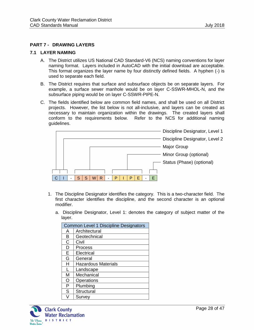
A. The District utilizes US National CAD Standard-V6 (NCS) naming conventions for layer naming format. Layers included in AutoCAD with the initial download are acceptable. This format organizes the layer name by four distinctly defined fields. A hyphen (-) is used to separate each field.
B. The District requires that surface and subsurface objects be on separate layers. For example, a surface sewer manhole would be on layer C-SSWR-MHOL-N, and the subsurface piping would be on layer C-SSWR-PIPE-N.
C. The fields identified below are common field names, and shall be used on all District projects. However, the list below is not all-inclusive, and layers can be created as necessary to maintain organization within the drawings. The created layers shall conform to the requirements below. Refer to the NCS for additional naming guidelines.
Discipline Designator, Level 1
Discipline Designator, Level 2
Major Group
Minor Group (optional)
Status (Phase) (optional)
C I - S S W R - P I P E - E
1. The Discipline Designator identifies the category. This is a two-character field. The first character identifies the discipline, and the second character is an optional modifier.
a. Discipline Designator, Level 1: denotes the category of subject matter of the layer.
Common Level 1 Discipline Designators
A Architectural
B Geotechnical
C Civil
D Process
E Electrical
G General
H Hazardous Materials
L Landscape
M Mechanical
O Operations
P Plumbing
S Structural
V Survey
Clark County Water Reclamation District July 15, 2015 CAD Standards Manual July 2018
Page 29 of 47
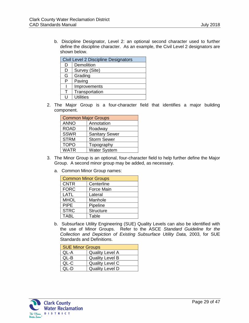
b. Discipline Designator, Level 2: an optional second character used to further define the discipline character. As an example, the Civil Level 2 designators are shown below.
Civil Level 2 Discipline Designators
D Demolition
D Survey (Site)
G Grading
P Paving
I Improvements
T Transportation
U Utilities
2. The Major Group is a four-character field that identifies a major building component.
Common Major Groups
ANNO Annotation
ROAD Roadway
SSWR Sanitary Sewer
STRM Storm Sewer
TOPO Topography
WATR Water System
3. The Minor Group is an optional, four-character field to help further define the Major Group. A second minor group may be added, as necessary.
a. Common Minor Group names:
Common Minor Groups
CNTR Centerline
FORC Force Main
LATL Lateral
MHOL Manhole
PIPE Pipeline
STRC Structure
TABL Table
b. Subsurface Utility Engineering (SUE) Quality Levels can also be identified with the use of Minor Groups. Refer to the ASCE Standard Guideline for the Collection and Depiction of Existing Subsurface Utility Data, 2003, for SUE Standards and Definitions.
SUE Minor Groups
QL-A Quality Level A
QL-B Quality Level B
QL-C Quality Level C
QL-D Quality Level D
Clark County Water Reclamation District July 15, 2015 CAD Standards Manual July 2018
Page 30 of 47
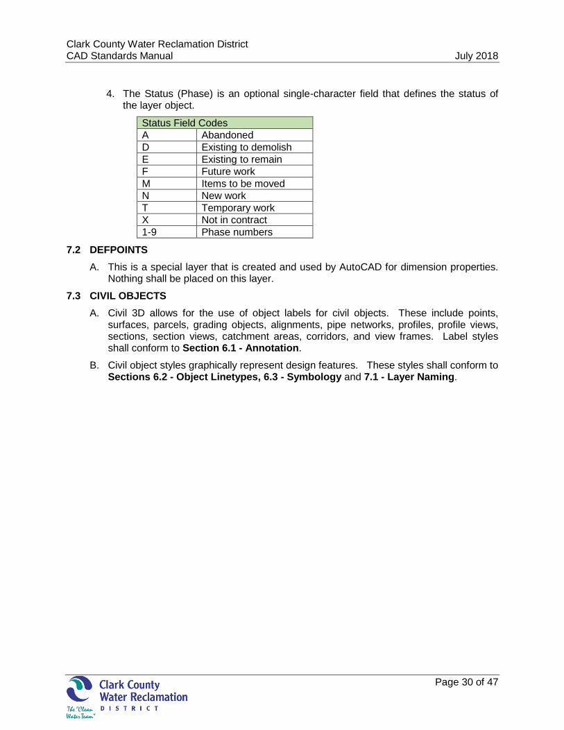
4. The Status (Phase) is an optional single-character field that defines the status of the layer object.
Status Field Codes
A Abandoned
D Existing to demolish
E Existing to remain
F Future work
M Items to be moved
N New work
T Temporary work
X Not in contract
1-9 Phase numbers
7.2 DEFPOINTS
A. This is a special layer that is created and used by AutoCAD for dimension properties. Nothing shall be placed on this layer.
7.3 CIVIL OBJECTS
A. Civil 3D allows for the use of object labels for civil objects. These include points, surfaces, parcels, grading objects, alignments, pipe networks, profiles, profile views, sections, section views, catchment areas, corridors, and view frames. Label styles shall conform to Section 6.1 - Annotation.
B. Civil object styles graphically represent design features. These styles shall conform to Sections 6.2 - Object Linetypes, 6.3 - Symbology and 7.1 - Layer Naming.

Clark County Water Reclamation District July 15, 2015 CAD Standards Manual July 2018
Page 31 of 47
THIS PAGE INTENTIONALLY LEFT BLANK
Clark County Water Reclamation District July 15, 2015 CAD Standards Manual July 2018
Page 32 of 47
PART 8 - ARCHITECTURAL, STRUCTURAL, MECHANICAL AND ELECTRICAL STANDARDS
To maintain consistency between different disciplines, all of the Standards listed in the previous Sections are applicable.

Clark County Water Reclamation District July 15, 2015 CAD Standards Manual July 2018
Page 33 of 47
THIS PAGE INTENTIONALLY LEFT BLANK
Clark County Water Reclamation District July 15, 2015 CAD Standards Manual July 2018
Page 34 of 47
PART 9 - SUBMITTAL REQUIREMENTS
9.1 SUBMITTAL REQUIREMENTS
A. Submittals shall be made in accordance with the contract scope.
B. Submittals shall be identified with “100% DRAWINGS”, “BID SET”, or “CONFORMED DOCUMENTS”, as applicable.
C. Electronic files will be submitted with the final design drawings, and as identified in the project contract.
D. Electronic submittals will include the entire folder structure, as identified in Section 5.2 - Folder Structure. Production drawing reference files shall be set to “Relative Path”. Do not use eTransmit to bind the reference files to the production drawing.
E. Electronic signatures will not be required for drawings submitted electronically.
F. If conformed drawings are produced, electronic versions of the conformed drawings will be provided in both .dwg and .pdf format.
G. If record drawings are produced, electronic files of the as-built drawings will be provided in both .dwg and .pdf format.
9.2 ELECTRONIC FILES
A. File transfers
1. File transfers shall be made in accordance with the contract scope.
2. The District requires that CAD files be submitted in the format that was available at the time of the project start, unless otherwise specified in the contract scope.
3. All drawings should be purged of unused blocks, line types, fonts, proxy graphics, or similar elements, and audited, with layers in the correct state for publishing (frozen/thawed) prior to delivery to the District.
4. Production drawings shall be saved with paper space set as the current view, zoomed to the extents of the drawing sheet.
5. Consultants using other software are responsible for confirming, prior to delivery to the District that all CAD files comply with the District standards.
6. The Consultant shall also scan files with the latest anti-virus detection software to ensure clean file transfers.
7. Documentation is expected to accompany all file transfers. Include project name and contract number on both hard copy documentation and CD.
B. Electronic files shall include the following:
1. Production drawings, external references, source drawings, images, custom line types, non-standard fonts, plot style files, and any other pertinent files or information.
2. Production drawings shall have all external references in their proper folder and properly attached to the drawing. External references are NOT to be bound into the drawing.

Clark County Water Reclamation District July 15, 2015 CAD Standards Manual July 2018
Page 35 of 47
3. A bookmarked pdf copy of the design drawings will be included for each volume of drawings. The bookmark will be named according to the bookmark number. Do not include the particular drawing name.
9.3 GIS DATA MANAGEMENT (UNDER DEVELOPMENT)
9.4 REPRODUCTION
A. Sheet Size
Sheet size shall be 22” x 34”. A larger sheet size may be used only with prior approval from the District Project Manager.
B. Paper Type
1. Paper type shall be 24# bright white (92 or better).
2. Mylar drawings will NOT be required for District submittals.
C. Plotting
1. All drawings shall be plotted to scale.
2. The District Project Manager may determine that a plotter’s output does not adequately show halftone and sold line definition. If so, the Project Manager will direct the Consultant to use the District’s reprographic vendor for plotting services.
a. Consultant shall check drawings for print quality and standards prior to submitting them to the District.
3. In general, all half-sized drawing sets are plotted full sized, and then reduced to half size for the printing process. All half size drawings shall be to scale.

Clark County Water Reclamation District July 15, 2015 CAD Standards Manual July 2018
Page 36 of 47
APPENDIX A - SYMBOLOGY
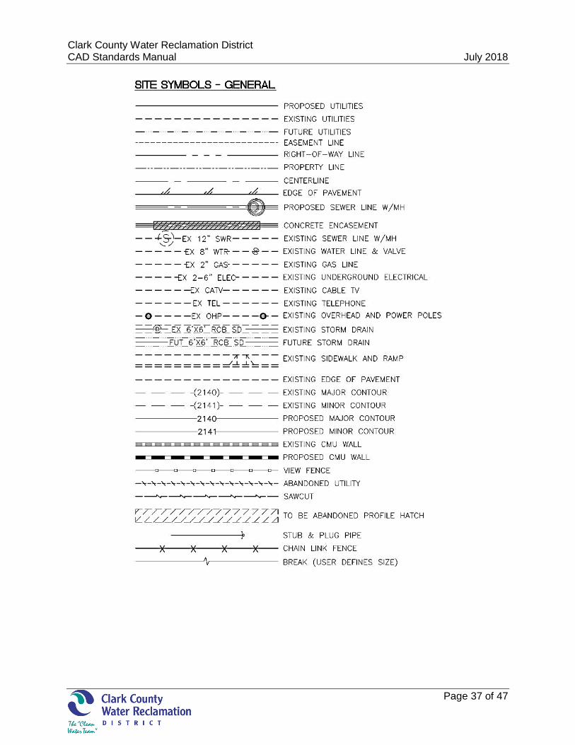
Clark County Water Reclamation District July 15, 2015 CAD Standards Manual July 2018
Page 37 of 47
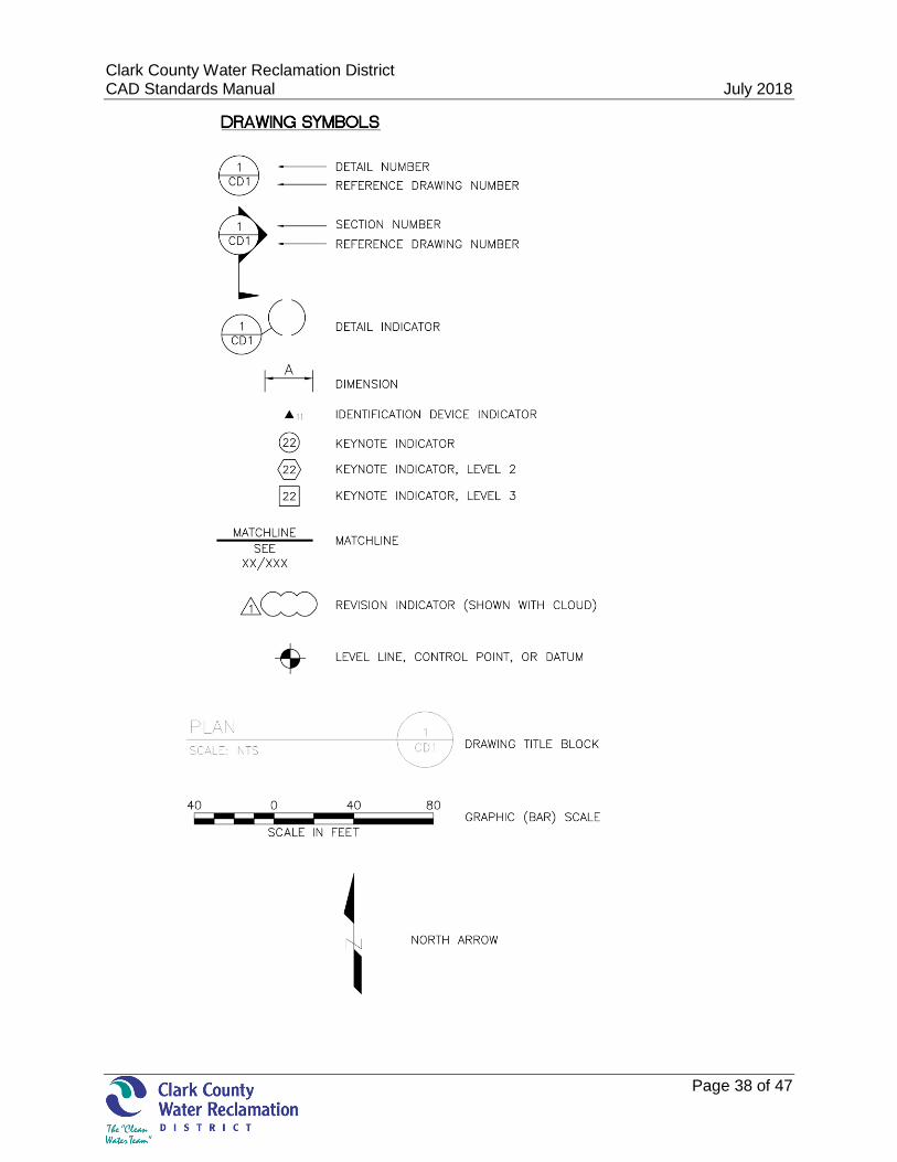
Clark County Water Reclamation District July 15, 2015 CAD Standards Manual July 2018
Page 38 of 47
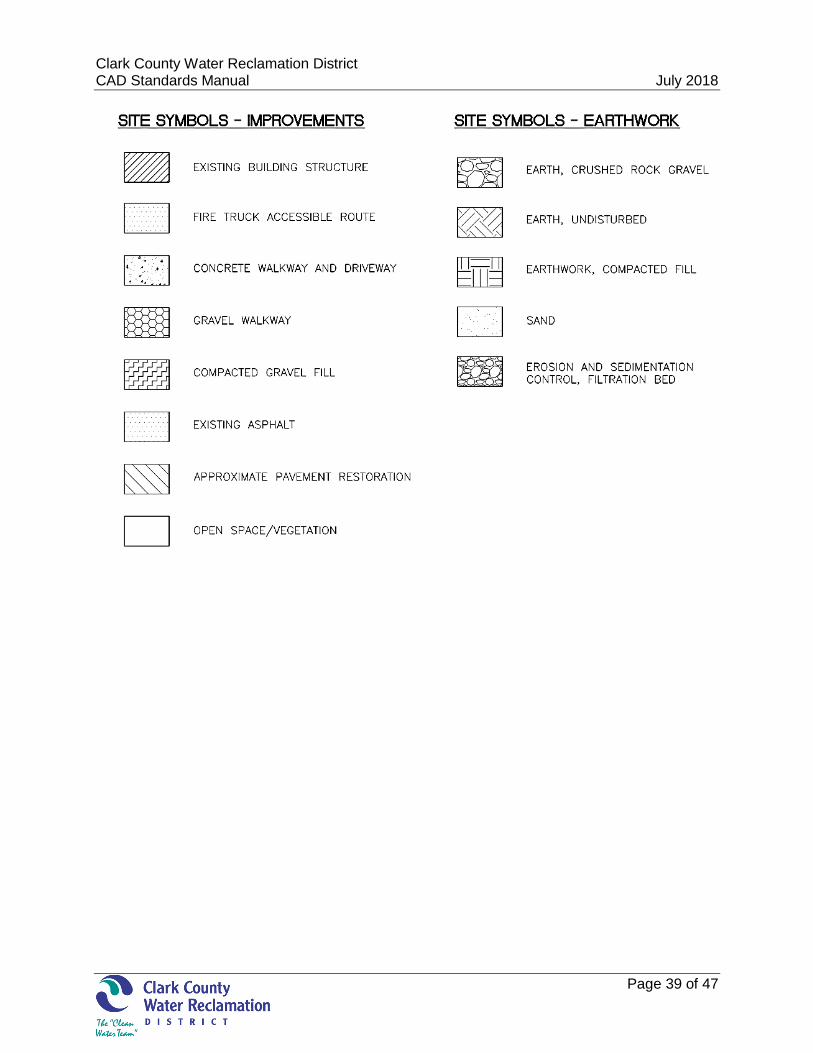
Clark County Water Reclamation District July 15, 2015 CAD Standards Manual July 2018
Page 39 of 47

Clark County Water Reclamation District July 15, 2015 CAD Standards Manual July 2018
Page 40 of 47
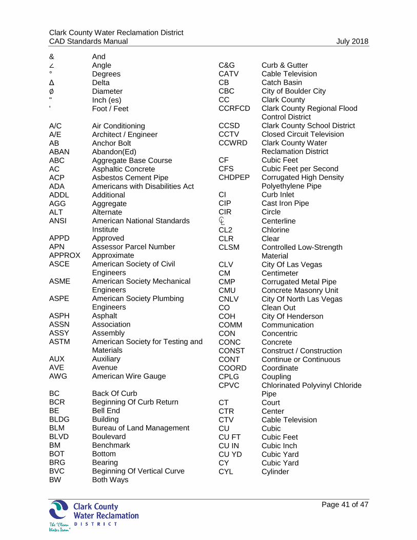
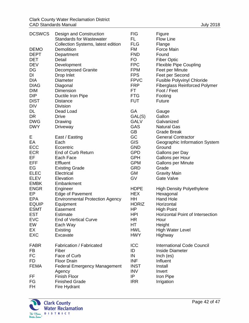
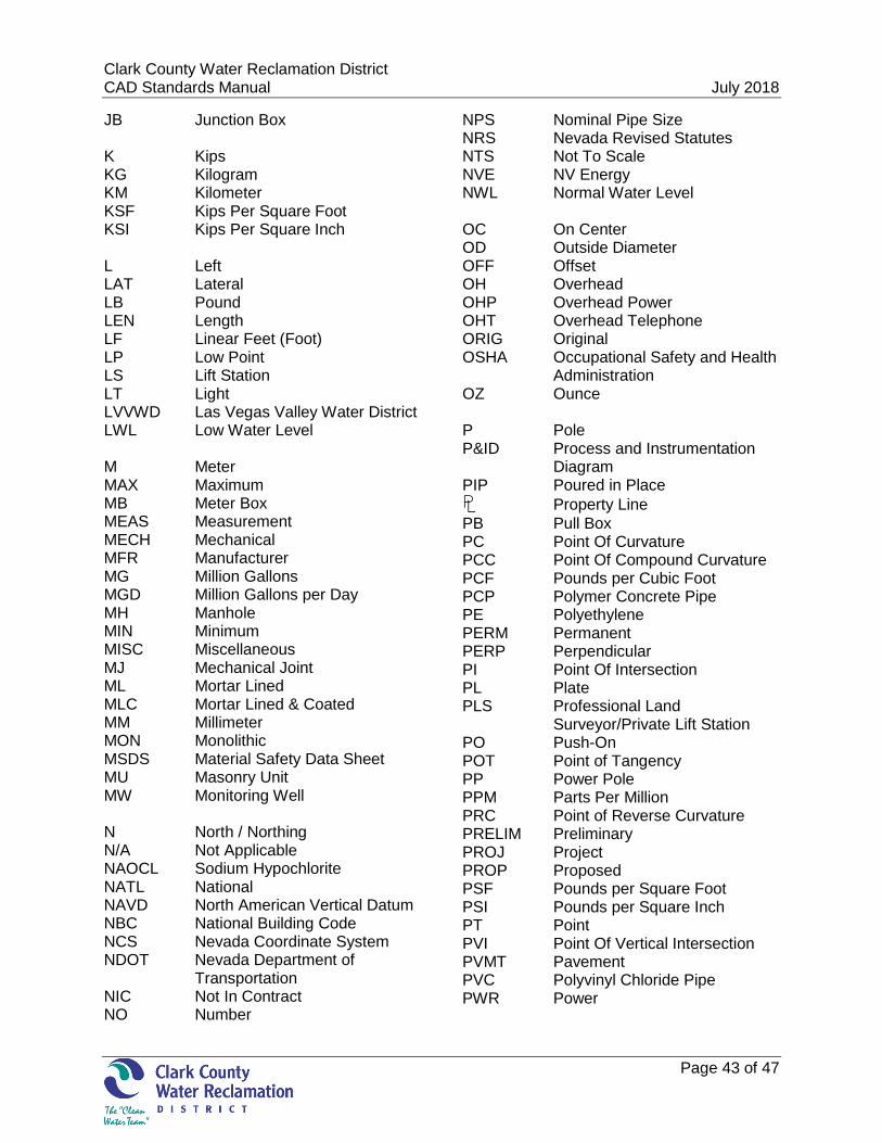
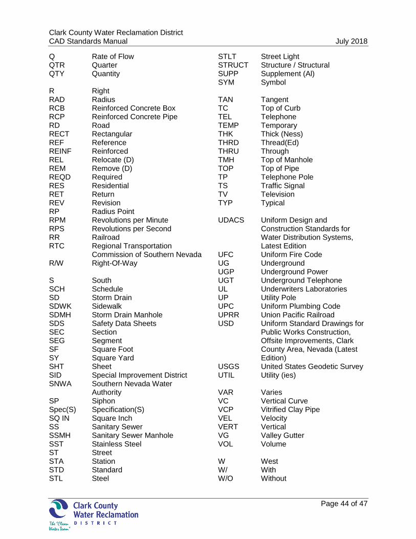
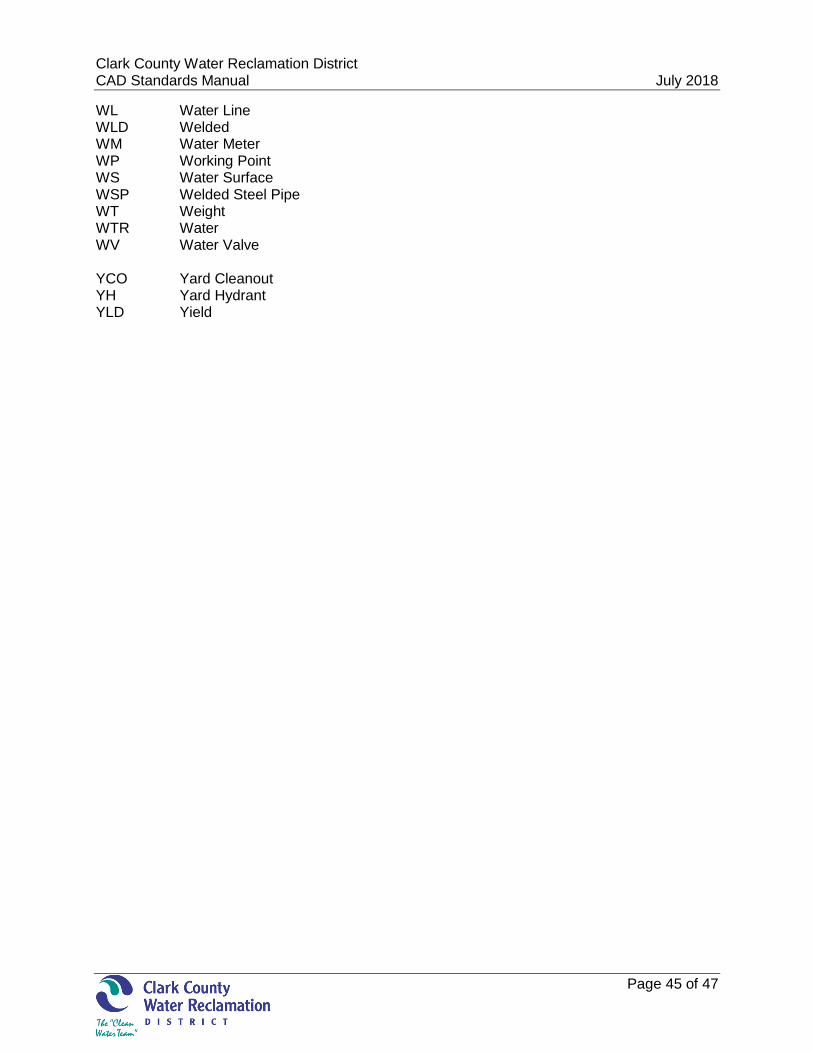
APPENDIX B - ABBREVIATIONS
Clark County Water Reclamation District July 15, 2015 CAD Standards Manual July 2018
Page 41 of 47
& And ∠ Angle ° Degrees Δ Delta ∅ Diameter " Inch (es) ' Foot / Feet A/C Air Conditioning A/E Architect / Engineer AB Anchor Bolt ABAN Abandon(Ed) ABC Aggregate Base Course AC Asphaltic Concrete ACP Asbestos Cement Pipe ADA Americans with Disabilities Act ADDL Additional AGG Aggregate ALT Alternate ANSI American National Standards
Institute APPD Approved APN Assessor Parcel Number APPROX Approximate ASCE American Society of Civil
Engineers ASME American Society Mechanical
Engineers ASPE American Society Plumbing
Engineers ASPH Asphalt ASSN Association ASSY Assembly ASTM American Society for Testing and
Materials AUX Auxiliary AVE Avenue AWG American Wire Gauge BC Back Of Curb BCR Beginning Of Curb Return BE Bell End BLDG Building BLM Bureau of Land Management BLVD Boulevard BM Benchmark BOT Bottom BRG Bearing BVC Beginning Of Vertical Curve BW Both Ways
C&G Curb & Gutter CATV Cable Television CB Catch Basin CBC City of Boulder City CC Clark County CCRFCD Clark County Regional Flood
Control District CCSD Clark County School District CCTV Closed Circuit Television CCWRD Clark County Water
Reclamation District CF Cubic Feet CFS Cubic Feet per Second CHDPEP Corrugated High Density
Polyethylene Pipe CI Curb Inlet CIP Cast Iron Pipe CIR Circle
℄ Centerline
CL2 Chlorine CLR Clear CLSM Controlled Low-Strength
Material CLV City Of Las Vegas CM Centimeter CMP Corrugated Metal Pipe CMU Concrete Masonry Unit CNLV City Of North Las Vegas CO Clean Out COH City Of Henderson COMM Communication CON Concentric CONC Concrete CONST Construct / Construction CONT Continue or Continuous COORD Coordinate CPLG Coupling CPVC Chlorinated Polyvinyl Chloride
Pipe CT Court CTR Center CTV Cable Television CU Cubic CU FT Cubic Feet CU IN Cubic Inch CU YD Cubic Yard CY Cubic Yard CYL Cylinder
Clark County Water Reclamation District July 15, 2015 CAD Standards Manual July 2018
Page 42 of 47
DCSWCS Design and Construction Standards for Wastewater Collection Systems, latest edition
DEMO Demolition DEPT Department DET Detail DEV Development DG Decomposed Granite DI Drop Inlet DIA Diameter DIAG Diagonal DIM Dimension DIP Ductile Iron Pipe DIST Distance DIV Division DL Dead Load DR Drive DWG Drawing DWY Driveway E East / Easting EA Each ECC Eccentric ECR End of Curb Return EF Each Face EFF Effluent EG Existing Grade ELEC Electrical ELEV Elevation EMBK Embankment ENGR Engineer EP Edge of Pavement EPA Environmental Protection Agency EQUIP Equipment ESMT Easement EST Estimate EVC End of Vertical Curve EW Each Way EX Existing EXC Excavate FABR Fabrication / Fabricated FB Fiber FC Face of Curb FD Floor Drain FEMA Federal Emergency Management
Agency FF Finish Floor FG Finished Grade FH Fire Hydrant
FIG Figure FL Flow Line FLG Flange FM Force Main FND Found FO Fiber Optic FPC Flexible Pipe Coupling FPM Feet per Minute FPS Feet per Second FPVC Fusible Polyvinyl Chloride FRP Fiberglass Reinforced Polymer FT Foot / Feet FTG Footing FUT Future GA Gauge GAL(S) Gallon GALV Galvanized GAS Natural Gas GB Grade Break GC General Contractor GIS Geographic Information System GND Ground GPD Gallons per Day GPH Gallons per Hour GPM Gallons per Minute GRD Grade GM Gravity Main GV Gate Valve HDPE High Density Polyethylene HEX Hexagonal HH Hand Hole HORIZ Horizontal HP High Point HPI Horizontal Point of Intersection HR Hour HT Height HWL High Water Level HWY Highway ICC International Code Council ID Inside Diameter IN Inch (es) INF Influent INST Install INV Invert IP Iron Pipe IRR Irrigation
Clark County Water Reclamation District July 15, 2015 CAD Standards Manual July 2018
Page 43 of 47
JB Junction Box K Kips KG Kilogram KM Kilometer KSF Kips Per Square Foot KSI Kips Per Square Inch L Left LAT Lateral LB Pound LEN Length LF Linear Feet (Foot) LP Low Point LS Lift Station LT Light LVVWD Las Vegas Valley Water District LWL Low Water Level M Meter MAX Maximum MB Meter Box MEAS Measurement MECH Mechanical MFR Manufacturer MG Million Gallons MGD Million Gallons per Day MH Manhole MIN Minimum MISC Miscellaneous MJ Mechanical Joint ML Mortar Lined MLC Mortar Lined & Coated MM Millimeter MON Monolithic MSDS Material Safety Data Sheet MU Masonry Unit MW Monitoring Well N North / Northing N/A Not Applicable NAOCL Sodium Hypochlorite NATL National NAVD North American Vertical Datum NBC National Building Code NCS Nevada Coordinate System NDOT Nevada Department of
Transportation NIC Not In Contract NO Number
NPS Nominal Pipe Size NRS Nevada Revised Statutes NTS Not To Scale NVE NV Energy NWL Normal Water Level OC On Center OD Outside Diameter OFF Offset OH Overhead OHP Overhead Power OHT Overhead Telephone ORIG Original OSHA Occupational Safety and Health
Administration OZ Ounce P Pole P&ID Process and Instrumentation
Diagram PIP Poured in Place
⅊ Property Line
PB Pull Box PC Point Of Curvature PCC Point Of Compound Curvature PCF Pounds per Cubic Foot PCP Polymer Concrete Pipe PE Polyethylene PERM Permanent PERP Perpendicular PI Point Of Intersection PL Plate PLS Professional Land
Surveyor/Private Lift Station PO Push-On POT Point of Tangency PP Power Pole PPM Parts Per Million PRC Point of Reverse Curvature PRELIM Preliminary PROJ Project PROP Proposed PSF Pounds per Square Foot PSI Pounds per Square Inch PT Point PVI Point Of Vertical Intersection PVMT Pavement PVC Polyvinyl Chloride Pipe PWR Power
Clark County Water Reclamation District July 15, 2015 CAD Standards Manual July 2018
Page 44 of 47
Q Rate of Flow QTR Quarter QTY Quantity R Right RAD Radius RCB Reinforced Concrete Box RCP Reinforced Concrete Pipe RD Road RECT Rectangular REF Reference REINF Reinforced REL Relocate (D) REM Remove (D) REQD Required RES Residential RET Return REV Revision RP Radius Point RPM Revolutions per Minute RPS Revolutions per Second RR Railroad RTC Regional Transportation Commission of Southern Nevada R/W Right-Of-Way S South SCH Schedule SD Storm Drain SDWK Sidewalk SDMH Storm Drain Manhole SDS Safety Data Sheets SEC Section SEG Segment SF Square Foot SY Square Yard SHT Sheet SID Special Improvement District SNWA Southern Nevada Water
Authority SP Siphon Spec(S) Specification(S) SQ IN Square Inch SS Sanitary Sewer SSMH Sanitary Sewer Manhole SST Stainless Steel ST Street STA Station STD Standard STL Steel
STLT Street Light STRUCT Structure / Structural SUPP Supplement (Al) SYM Symbol TAN Tangent TC Top of Curb TEL Telephone TEMP Temporary THK Thick (Ness) THRD Thread(Ed) THRU Through TMH Top of Manhole TOP Top of Pipe TP Telephone Pole TS Traffic Signal TV Television TYP Typical UDACS Uniform Design and
Construction Standards for Water Distribution Systems, Latest Edition
UFC Uniform Fire Code UG Underground UGP Underground Power UGT Underground Telephone UL Underwriters Laboratories UP Utility Pole UPC Uniform Plumbing Code UPRR Union Pacific Railroad USD Uniform Standard Drawings for
Public Works Construction, Offsite Improvements, Clark County Area, Nevada (Latest Edition)
USGS United States Geodetic Survey UTIL Utility (ies) VAR Varies VC Vertical Curve VCP Vitrified Clay Pipe VEL Velocity VERT Vertical VG Valley Gutter VOL Volume W West W/ With W/O Without
Clark County Water Reclamation District July 15, 2015 CAD Standards Manual July 2018
Page 45 of 47
WL Water Line WLD Welded WM Water Meter WP Working Point WS Water Surface WSP Welded Steel Pipe WT Weight WTR Water WV Water Valve YCO Yard Cleanout YH Yard Hydrant YLD Yield

Clark County Water Reclamation District July 15, 2015 CAD Standards Manual July 2018
Page 46 of 47
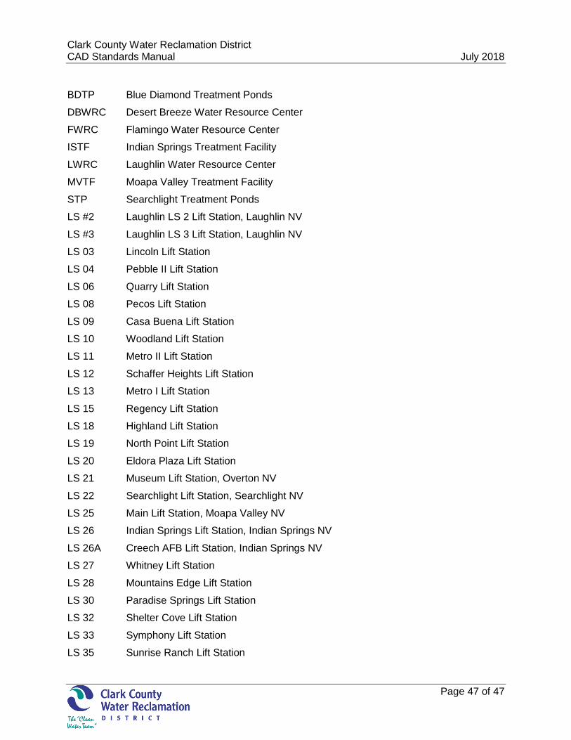
APPENDIX C – FACILITY CODES
Clark County Water Reclamation District July 15, 2015 CAD Standards Manual July 2018
Page 47 of 47
BDTP Blue Diamond Treatment Ponds
DBWRC Desert Breeze Water Resource Center
FWRC Flamingo Water Resource Center
ISTF Indian Springs Treatment Facility
LWRC Laughlin Water Resource Center
MVTF Moapa Valley Treatment Facility
STP Searchlight Treatment Ponds
LS #2 Laughlin LS 2 Lift Station, Laughlin NV
LS #3 Laughlin LS 3 Lift Station, Laughlin NV
LS 03 Lincoln Lift Station
LS 04 Pebble II Lift Station
LS 06 Quarry Lift Station
LS 08 Pecos Lift Station
LS 09 Casa Buena Lift Station
LS 10 Woodland Lift Station
LS 11 Metro II Lift Station
LS 12 Schaffer Heights Lift Station
LS 13 Metro I Lift Station
LS 15 Regency Lift Station
LS 18 Highland Lift Station
LS 19 North Point Lift Station
LS 20 Eldora Plaza Lift Station
LS 21 Museum Lift Station, Overton NV
LS 22 Searchlight Lift Station, Searchlight NV
LS 25 Main Lift Station, Moapa Valley NV
LS 26 Indian Springs Lift Station, Indian Springs NV
LS 26A Creech AFB Lift Station, Indian Springs NV
LS 27 Whitney Lift Station
LS 28 Mountains Edge Lift Station
LS 30 Paradise Springs Lift Station
LS 32 Shelter Cove Lift Station
LS 33 Symphony Lift Station
LS 35 Sunrise Ranch Lift Station