Embed Size (px)
Citation preview
XFEL.EU TN-2012-001-01
TECHNICAL NOTE
CAD Integration Guidelines for Photon Beamline Components
January 2012
N. Kohlstrunk
for X-Ray Optics and Beam Transport (WP73)

January 2012 XFEL.EU TN-2012-001-01 2 of 24 CAD Integration Guidelines for Photon Beamline Components
Contents
1 Introduction ............................................................................................3
2 Component list .......................................................................................4
2.1 Structure of the component list ....................................................5 2.1.1 Component list colours .................................................. 5 2.1.2 Component list columns ................................................. 5 2.1.3 Component types ........................................................... 6
2.2 Change requests .........................................................................7
3 Working in SPPS ....................................................................................8
3.1 Structure of SPPS .......................................................................9 3.2 Overview assemblies of photon beamlines ................................ 10
4 Building up CAD files ........................................................................... 12
4.1 Working in SPPS with Solid Edge (preferred case) .................... 13 4.2 Working locally on the computer (exception).............................. 13
4.2.1 Starting the Set Properties program ..............................14 4.2.2 Starting the Rename program .......................................15
4.3 Drawings ................................................................................... 16 4.3.1 Creating a new drawing ................................................16 4.3.2 English-language title block ..........................................17 4.3.3 English-language BOM .................................................18
5 CAD Integration process ...................................................................... 19
5.1 Preferred use case .................................................................... 19 5.1.1 Creating a model ..........................................................19 5.1.2 Creating a placeholder ..................................................20 5.1.3 Integrating the model into EDMS ..................................20
5.2 Workaround use case ................................................................ 21
6 Components ......................................................................................... 22
6.1 Building a new component ......................................................... 22 6.1.1 German-language user interface ..................................22 6.1.2 English-language user interface ....................................23
6.2 Changing a component .............................................................. 24 6.3 Viewing a component or part of a beamline ............................... 24

XFEL.EU TN-2012-001-01 January 2012 CAD Integration Guidelines for Photon Beamline Components 3 of 24
1 Introduction
This document presents guidelines for the computer-aided design (CAD)
integration of photon beamline components at the European XFEL facility.
The guidelines are valid for all people designing components for the photon
beamlines. Follow these guidelines when exchanging and sharing information
between work packages and the quality assurance (QA) team of DESY.
This document contains rules and important information about working with
the existing component list and the structure of the SharePoint Portal Server
(SPPS). It describes the general routine for creating CAD files and where to
put CAD working data. Furthermore, it shows how to make a change request
for shifting the position of components in the tunnel.

January 2012 XFEL.EU TN-2012-001-01 4 of 24 CAD Integration Guidelines for Photon Beamline Components
2 Component list
The component list provides an overview of all devices with their particular
position in the photon beamlines. Each value in the table (except the
length S) always describes the middle of each component with respect to the
z-direction of the Linear Accelerator (LA) coordinate system. The component
list is provided by the CAD integration coordinator of WP73 (Nicole
Kohlstrunk).
The current component list for SASE1, SASE2, and SASE3 is available in
EDMS (D*2278111) and is updated every six months. Figure 1 shows an
abstract of the component list of SASE1.
Figure 1: Component list of SASE1 (extract)
XFEL.EU TN-2012-001-01 January 2012 CAD Integration Guidelines for Photon Beamline Components 5 of 24
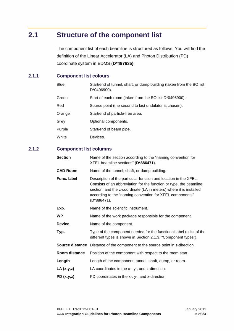
2.1 Structure of the component list
The component list of each beamline is structured as follows. You will find the
definition of the Linear Accelerator (LA) and Photon Distribution (PD)
coordinate system in EDMS (D*497635).
2.1.1 Component list colours
Blue Start/end of tunnel, shaft, or dump building (taken from the BO list D*0496900).
Green Start of each room (taken from the BO list D*0496900).
Red Source point (the second to last undulator is chosen).
Orange Start/end of particle-free area.
Grey Optional components.
Purple Start/end of beam pipe.
White Devices.
2.1.2 Component list columns
Section Name of the section according to the “naming convention for XFEL beamline sections” (D*886471).
CAD Room Name of the tunnel, shaft, or dump building.
Func. label Description of the particular function and location in the XFEL. Consists of an abbreviation for the function or type, the beamline section, and the z-coordinate (LA in meters) where it is installed according to the “naming convention for XFEL components” (D*886471).
Exp. Name of the scientific instrument.
WP Name of the work package responsible for the component.
Device Name of the component.
Typ. Type of the component needed for the functional label (a list of the different types is shown in Section 2.1.3, “Component types”).
Source distance Distance of the component to the source point in z-direction.
Room distance Position of the component with respect to the room start.
Length Length of the component, tunnel, shaft, dump, or room.
LA (x,y,z) LA coordinates in the x-, y-, and z-direction.
PD (x,y,z) PD coordinates in the x-, y-, and z-direction

January 2012 XFEL.EU TN-2012-001-01 6 of 24 CAD Integration Guidelines for Photon Beamline Components
2.1.3 Component types
APT Aperture
XBPM X-ray beam position monitor
XGMD X-ray gas monitor detector
SRA Spontaneous radiation aperture
ATT Attenuator
KMON K-monochromator
MONO Monochromator
IMAG Imager / pop-in monitor
COLL Collimator
MIRR Mirror
MCP Multi-channel plate detector
PES Photo electron spectrometer
ABS FEL beam absorber
BSTP Bremsstrahlung beam stop
SHUT Shutter
VLSG Variable line spacing grating
SLIT Exit slit

XFEL.EU TN-2012-001-01 January 2012 CAD Integration Guidelines for Photon Beamline Components 7 of 24
2.2 Change requests
If something in the component list has to be changed (e.g. the position of a
device has to be shifted upstream or downstream), submit a change request
to the CAD integration coordinator explaining what should be changed and
why. The CAD integration coordinator then puts the change request into a
separate list in EDMS (change request component list D*2629421) indicating
the date, the name and work package of the requester, the description, and
the influence on other devices. Whenever there is a new change request, this
list is updated and routed to everyone in charge of designing components for
the photon beamlines. When you receive a new list, make sure there are no
mistakes and no reasons the change request cannot be approved.
Requested changes are marked red in the history of the component list.
Approved changes appear in yellow in the component list. When they are
adapted in the CAD model, they turn green.
Figure 2 shows the change history of the component list.
Figure 2: Change history of component list
January 2012 XFEL.EU TN-2012-001-01 8 of 24 CAD Integration Guidelines for Photon Beamline Components
3 Working in SPPS
The SharePoint Portal Server (SPPS) is a document management system
provided by Microsoft. Acting as a portal, SharePoint is able to make data
available centrally. It enables different people and groups to share information
and to work on the same data or projects.
“View & Markup” and “RevisionManager” include tools for design
management and administration. They are part of Solid Edge with an
interface to SPPS. Together, they are called “Insight Connect”.
The SharePoint Portal Server consists of two computers. One serves as an
SQL server. Together with “Insight Connect”, it is called the SharePoint Portal
System.
The CAD data in the SPPS can be reached in one of two ways:
Solid Edge
Open → Computer → SE_SPPS_II
Internet Explorer
http://adsepsps2/sites/SE_CAD
To avoid mistakes that might cause data loss, it is very important to follow
certain rules when working with the SPPS.
The DESY IPP group provides a training course called “Document
Management with Solid Edge and SharePoint Portal Server“
(“Dokumentenverwaltung mit Solid Edge und SharePoint Portal Server”).
You can register for the course from the IPP website:
http://www.desy.de/ipp/Anwendersupport/Schulungen/schulungen.html
The courses are typically provided in German. IPP offers an English-language
Solid Edge course (with the German-language user interface) if there are
enough participants (minimum of eight). When applying for the course,
indicate which language you prefer.

XFEL.EU TN-2012-001-01 January 2012 CAD Integration Guidelines for Photon Beamline Components 9 of 24
This course and a minimum basic knowledge of Solid Edge are required to
get access to the SPPS. It is also mandatory to use the German-language
user interface of SPPS and the German-language version of Solid Edge.
CAUTION: If you work with the English-language version in SPPS, files can be destroyed because
Solid Edge and SPPS “wire” file attributes differently in different languages. These problems may
occur only after a while. Also, if you work with the English-language version of Solid Edge, it is
possible to work locally on a computer only. In this case, the Solid Edge macros are not available.
3.1 Structure of SPPS
At the top of the structure are the sites (Arbeitsbereiche), followed by the
libraries (Bibliotheken), folders (Ordner), and subfolders (Unterordner).
The “EXFEL” site contains libraries for each work package and group that
works with CAD data.
Work packages can create folders and subfolders within their library.
In the current SPPS version, it is possible to give write access to others on
folder level.
The name of each folder and file name and the structure is to be kept as short
and flat as possible.
It is only allowed to use following characters for folder and file names:
0-9, a-z, A-Z, hyphen (-) or underscore (_)
For SPPS guidelines, go to the following site:
\\ippfatcad\cad\web4tools\se\richtlinien\spps\index_rili_spps.htm
The structure (as of September 2011) of the EXFEL site is shown in Figure 3.

January 2012 XFEL.EU TN-2012-001-01 10 of 24 CAD Integration Guidelines for Photon Beamline Components
EXFEL
SASE XOBTInstrumentsDiagnostic
Beam_Transport
X-ray_Optics
Vacuum
CAD_Int
Experiments
FXE
HED
MID
SCS
SPB
SQS
Hall_5
I_section
Undulator
LCLS
time_tool
Diamond_detector
K-Mono
…
…
…
…
Site („Arbeitsbereich“)
Library („Bibliothek“)
Folder („Ordner“)
Figure 3: CAD integration structure of the EXFEL site in SPPS
3.2 Overview assemblies of photon beamlines
The overview assemblies are a formation of the rooms of one tunnel section.
They are available for all beamlines from the room with the e-beam
separation until the last tunnel room before the experiment hall.
The overview assemblies for the beamlines can be found in SPPS at
EXFEL → XOBT → CAD_Int → SASE1/SASE2/SASE3.
The overview assemblies for the different sections of the beamlines are:
SASE1 ASM_XTD2_R9-R16-SE000398612.asm
ASM_XS3-SE000414101.asm
ASM_XTD9_R1-R11-SE000414821.asm
SASE2 ASM_XTD1_R9-R11-SE000399490.asm
ASM_XS2-SE000416837.asm
ASM_XTD6_R1-R13-SE000417732.asm
SASE3 ASM_XTD4_R6-R7-SE000402089.asm
ASM_XSDU2-SE000402095.asm
ASM_XTD10_R1-R5-SE000402105.asm
The overview assemblies are structured room by room. The filename of each
room indicate the tunnel, shaft or dump name, room number, “complete”, SE
number. Each part of the filename is divided by an underscore (_) or
hyphen (-).
XFEL.EU TN-2012-001-01 January 2012 CAD Integration Guidelines for Photon Beamline Components 11 of 24
Example:
XTD2_R13_complete-SE000xxxxxx.asm
Each room contains the assemblies of Work Package 34—DESY group
Maschine, Kraft, Kühlung (MKK)—with the tunnel itself, as well as the cabling,
water cooling, and components of other work packages, such WP32 (survey
and alignment), and all components of WP73 and WP74.
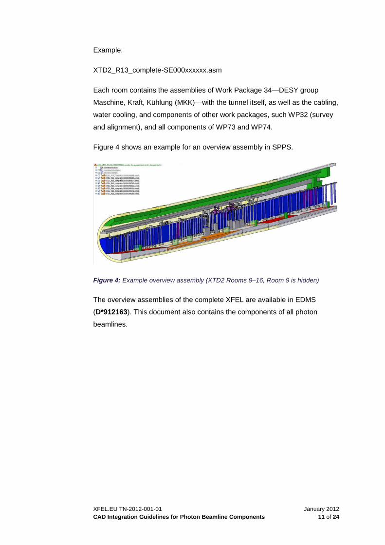
Figure 4 shows an example for an overview assembly in SPPS.
Figure 4: Example overview assembly (XTD2 Rooms 9–16, Room 9 is hidden)
The overview assemblies of the complete XFEL are available in EDMS
(D*912163). This document also contains the components of all photon
beamlines.
January 2012 XFEL.EU TN-2012-001-01 12 of 24 CAD Integration Guidelines for Photon Beamline Components
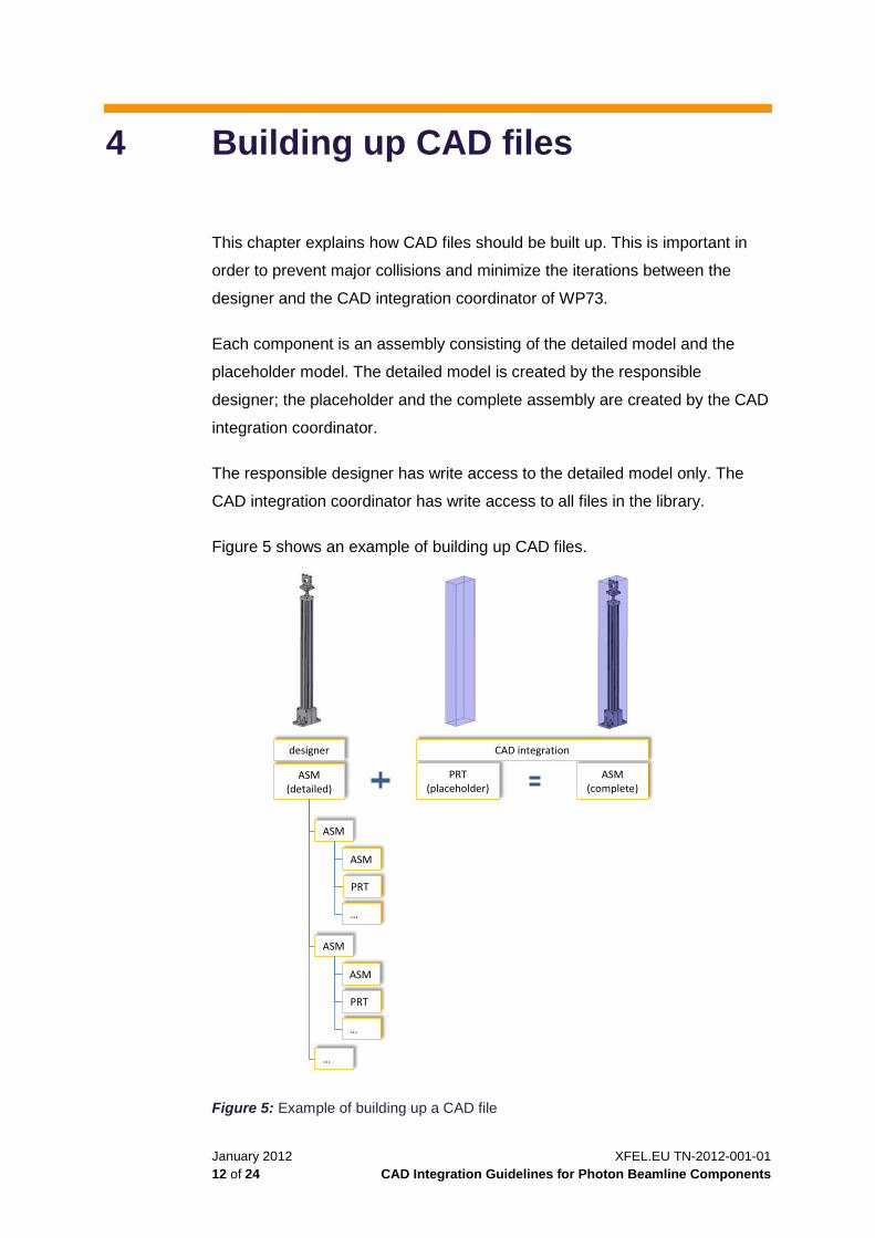
4 Building up CAD files
This chapter explains how CAD files should be built up. This is important in
order to prevent major collisions and minimize the iterations between the
designer and the CAD integration coordinator of WP73.
Each component is an assembly consisting of the detailed model and the
placeholder model. The detailed model is created by the responsible
designer; the placeholder and the complete assembly are created by the CAD
integration coordinator.
The responsible designer has write access to the detailed model only. The
CAD integration coordinator has write access to all files in the library.
Figure 5 shows an example of building up CAD files.
Figure 5: Example of building up a CAD file
ASM (complete)
ASM (detailed)
PRT (placeholder)
ASM
…
ASM
ASM
PRT
…
…
ASM
PRT
designer CAD integration

XFEL.EU TN-2012-001-01 January 2012 CAD Integration Guidelines for Photon Beamline Components 13 of 24
The detailed 3D model has to stay within the length given in the component
list. If the model is shorter, it has to be extended to the margins with pipes.
The diameter of the connecting flanges should also be chosen according to
the component list.
4.1 Working in SPPS with Solid Edge (preferred case)
Working with the German-language user interface of Solid Edge is the
preferred use case because it is easiest and fastest. Collisions can be seen
directly and files are in SPPS from the beginning.
When working in SPPS on the detailed model, open the complete model first,
and then open the detailed model from there. That way, it is easier to
recognize collisions between the placeholder and the detailed model.
The detailed model should stay within the boundaries of the placeholder
model. If there are any collisions with the placeholder model that cannot be
avoided, discuss the problem with the CAD integration coordinator.
4.2 Working locally on the computer (exception)
It is not possible to put a Solid Edge file created with the English-language
user interface directly into a complete model because there cannot be a
mixture of managed and unmanaged documents. Therefore, when working
locally on a computer with the English-language user interface of Solid Edge
or another 3D CAD program, create a STEP file of the detailed 3D model and
send it to the CAD integration coordinator. The CAD integration coordinator
will then change it into a Solid Edge file and integrate it into the complete
model. In this case, collisions are checked by the CAD integration
coordinator.
When the detailed model is finished, it should be put into the SPPS.

January 2012 XFEL.EU TN-2012-001-01 14 of 24 CAD Integration Guidelines for Photon Beamline Components
Files created with the English-language version of Solid Edge have to be
specially prepared by the designer. Each file needs an SE number (in the
attribute field of the file and at the end of the filename). IPP provides two
programs that perform these steps automatically.
4.2.1 Starting the Set Properties program
The Set Properties program creates an SE number for every file created with
the English-language version of Solid Edge. It puts the SE number in the
attributes field of a log file for the Solid Edge file.
To start the Set Properties program, follow these steps:
1 Click the Set Properties link:
//ippfatcad/SolidEdge/system/4all_vers/Programme
/DatSys-SPPS/SetProps-mit-Nummer.exe
2 Click OK.
The following window displays.
3 Choose the directory (1).
4 Choose the type of processing (2).
There are three different types of processing (from top):
□ All files in choosen directory (“Alle Dateien im gewählten
Verzeichnis”)
□ Only marked files (“Nur markierte Dateien”)
□ All files in chosen directory and subdirectory (“Alle Dateien im
gewählten Verzeichnis und Unterverzeichnissen”)
(1) (2)
(3)

XFEL.EU TN-2012-001-01 January 2012 CAD Integration Guidelines for Photon Beamline Components 15 of 24
5 Start processing (3) by clicking Ausführen.
4.2.2 Starting the Rename program
The Rename program adds the SE number from the attribute field of the log
file to the end of the filename for the Solid Edge file.
To start the Rename program, follow these steps:
1 Click the Rename link:
//ippfatcad/SolidEdge/system/4all_vers/Programme
/DatSys-SPPS/Rename-mit-Nummer.exe
2 Confirm the subsequent two messages by clicking OK twice.
The following window displays.
3 Choose the directory (1) and the type of processing (2).
For details, see “Starting the Set Properties program” on page 14.
The check mark in (3) “reporting only” (“Nur Auswertung”) is set by
default. In this case only a log file is generated showing the action that
would be committed.
4 Remove the check mark in the box (3) “reporting only” (“Nur
Auswertung”).
5 Execute (4) by clicking Ausführen.
The program puts the SE number behind the file name.
Now the CAD integration coordinator can check the attributes of the files and
add all files to the library in SPPS.
(1)
(2)
(3)
(4)

January 2012 XFEL.EU TN-2012-001-01 16 of 24 CAD Integration Guidelines for Photon Beamline Components
After all files of the detailed 3D model have been added to the library, the
detailed model can also be integrated in the complete 3D model by the CAD
integration coordinator.
4.3 Drawings
For technical drawings, there is a template with the corporate title block
available in Solid Edge. This template was created in collaboration with
engineers from several work packages and was approved by the European
XFEL Management Board.
4.3.1 Creating a new drawing
To create a new drawing in Solid Edge, follow these steps:
1 Click Neu (“new”).
The following window displays.
2 Open the XFEL_din draft.dft template.

XFEL.EU TN-2012-001-01 January 2012 CAD Integration Guidelines for Photon Beamline Components 17 of 24
4.3.2 English-language title block
Use the new template to create a technical drawing with an English-language
title block. This title block is shown in Figure 6.
Figure 6: English-language title block for a Solid Edge drawing
The fields of the title block can be filled with the macro “SE Tools” (only
available with the German-language user interface) or in the file attributes of
the part, assembly, etc., as shown in Figure 7.
Figure 7: File attributes in Solid Edge
To find the file attributes in Solid Edge, follow these steps:
1 Click Eigenschaften (properties) → Dateieigenschaften (“file
properties”).
2 Click Info → Projekt (“project”) → Benutzerdefiniert (“user-defined“).
January 2012 XFEL.EU TN-2012-001-01 18 of 24 CAD Integration Guidelines for Photon Beamline Components
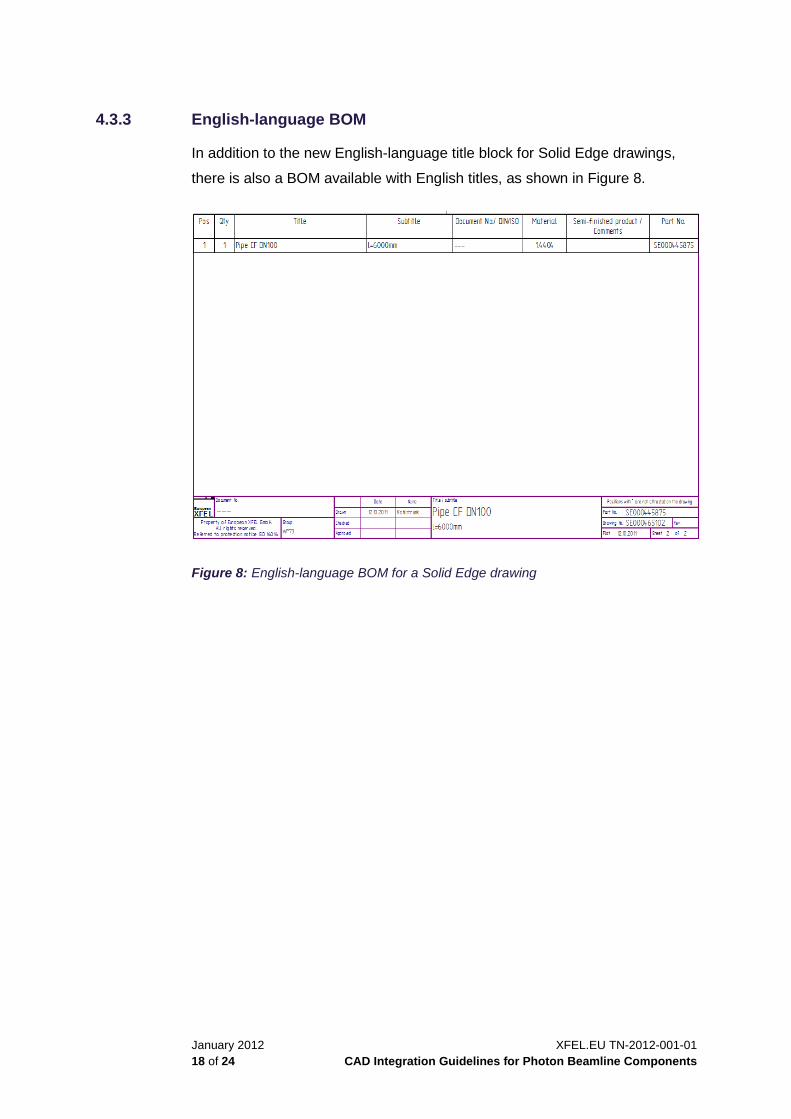
4.3.3 English-language BOM
In addition to the new English-language title block for Solid Edge drawings,
there is also a BOM available with English titles, as shown in Figure 8.
Figure 8: English-language BOM for a Solid Edge drawing
XFEL.EU TN-2012-001-01 January 2012 CAD Integration Guidelines for Photon Beamline Components 19 of 24
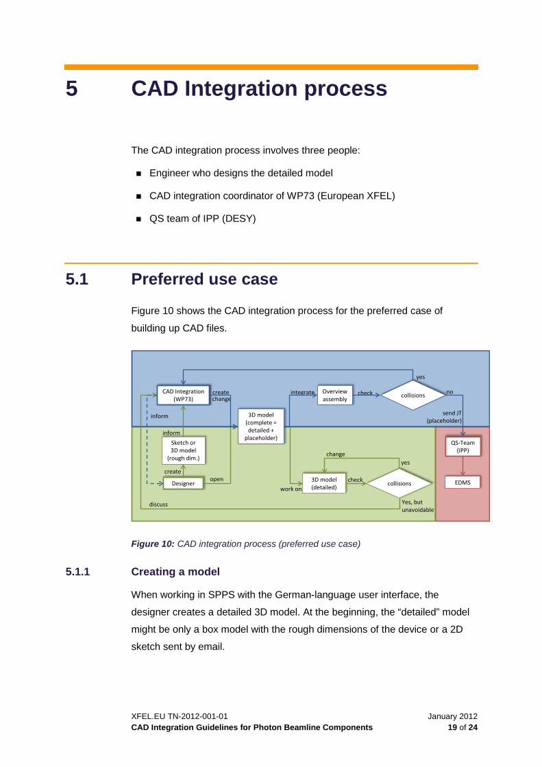
5 CAD Integration process
The CAD integration process involves three people:
Engineer who designs the detailed model
CAD integration coordinator of WP73 (European XFEL)
QS team of IPP (DESY)
5.1 Preferred use case
Figure 10 shows the CAD integration process for the preferred case of
building up CAD files.
Designer
Sketch or3D model
(rough dim.)
CAD Integration (WP73)
create
3D model(complete = detailed +
placeholder)
create
open
Overviewassembly
integrate
Yes, but unavoidable
QS-Team (IPP)
collisions
yes
check
no
EDMS
yes
collisions
check
work on
send JT (placeholder)
inform
inform
3D model(detailed)
change
change
discuss
Figure 10: CAD integration process (preferred use case)
5.1.1 Creating a model
When working in SPPS with the German-language user interface, the
designer creates a detailed 3D model. At the beginning, the “detailed” model
might be only a box model with the rough dimensions of the device or a 2D
sketch sent by email.

January 2012 XFEL.EU TN-2012-001-01 20 of 24 CAD Integration Guidelines for Photon Beamline Components
When the model is complete, the designer tells the CAD integration
coordinator where to find the detailed model in SPPS, so it can be integrated
into the complete 3D model.
CAUTION: To avoid massive collisions with other components in the tunnel, these first steps should
be performed as early as possible in the design process.
5.1.2 Creating a placeholder
Knowing the rough dimensions of the device, the CAD integration coordinator
creates a placeholder model.
After the detailed model is integrated into the complete 3D model, the detailed
model should always stay within the margins of the placeholder. If collisions
are unavoidable, the designer has to discuss with the CAD integration
coordinator whether the complete 3D model could be changed without
causing new collisions with components of other work packages or the tunnel
itself. If this is not possible, the designer has to change the detailed model.
When the complete 3D model is integrated into the overview assembly, the
CAD integration coordinator checks whether there are any collisions between
the 3D model and the overview assembly. If there are collisions, the 3D
model has to be changed. If the change of the complete 3D model again
causes collisions between the placeholder and the detailed model, the CAD
integration coordinator informs the designer.
5.1.3 Integrating the model into EDMS
If there are no collisions between the detailed and placeholder models, or
between the 3D model and the overview assembly, the CAD integration
coordinator sends a JT file (consisting only of the placeholder models) to the
quality assurance (Qualitätssicherung = QS) team. The QS team integrates
the JT file into EDMS.
After the 3D model is integrated into EDMS, everyone can view the 3D model
with the 3D viewer, VisView, available via NetInstall.

XFEL.EU TN-2012-001-01 January 2012 CAD Integration Guidelines for Photon Beamline Components 21 of 24
5.2 Workaround use case
If you are working locally on a computer, the CAD integration process is
slightly different, as shown in Figure 11. This workaround use case is more
extensive (especially for the CAD integration coordinator). Use it only when it
is not possible to work in SPPS.
Designer
Sketch or3D model
(rough dim.)
CAD Integration (WP73)
create
3D model(complete + placeholder)
create
change
Overviewassembly
integrate
QS-Team (IPP)
collisions
yes
check
no
EDMS
yes
check
integrate
send JT (placeholder)
inform
inform
change
discuss
3D model(placeholder)
send
collisions
Yes, but unavoidable
Figure 11: CAD integration process (workaround)
In this workaround process, the designer sends an email of a box model or a
2D sketch with rough dimensions to the CAD integration coordinator, who
creates the placeholder and integrates it into the complete 3D model.
The CAD integration coordinator sends the placeholder to the designer so
that the checking of collisions between the placeholder and the detailed
model can be done by the designer.
The detailed 3D model should be send as a STEP file to the CAD integration
coordinator to be integrated into the complete 3D model.

January 2012 XFEL.EU TN-2012-001-01 22 of 24 CAD Integration Guidelines for Photon Beamline Components
6 Components
This chapter describes how to build, change, and view components.
6.1 Building a new component
Before building a new component, write an email to the CAD integration
coordinator of WP73, Nicole Kohlstrunk ([email protected]), with a
copy to Harald Sinn ([email protected]) and Martin Dommach
([email protected]). This email should contain the position of the
component, its total length, and a sketch of the component with the
approximate dimensions, as well as the electricity and water requirements,
the weight, and the vacuum conditions.
With these details, the CAD integration coordinator is able to create a 3D
placeholder model. This placeholder model also contains the space for
assembly and disassembly.
6.1.1 German-language user interface
With the Solid Edge German-language user interface, you build a new
component as follows:
CAD integration coordinator
□ Provides the complete assembly, consisting of the placeholder model
and an empty file for the designer, where the detailed model has to
be created.
□ Passes the location or the SE number of these models to the
designer.
□ Tells the designer the size of the connecting flanges or the
responsible person.
XFEL.EU TN-2012-001-01 January 2012 CAD Integration Guidelines for Photon Beamline Components 23 of 24
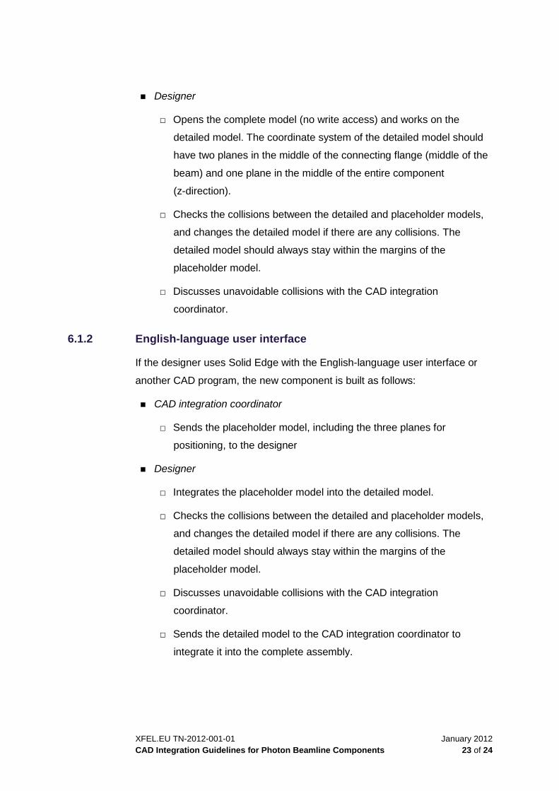
Designer
□ Opens the complete model (no write access) and works on the
detailed model. The coordinate system of the detailed model should
have two planes in the middle of the connecting flange (middle of the
beam) and one plane in the middle of the entire component
(z-direction).
□ Checks the collisions between the detailed and placeholder models,
and changes the detailed model if there are any collisions. The
detailed model should always stay within the margins of the
placeholder model.
□ Discusses unavoidable collisions with the CAD integration
coordinator.
6.1.2 English-language user interface
If the designer uses Solid Edge with the English-language user interface or
another CAD program, the new component is built as follows:
CAD integration coordinator
□ Sends the placeholder model, including the three planes for
positioning, to the designer
Designer
□ Integrates the placeholder model into the detailed model.
□ Checks the collisions between the detailed and placeholder models,
and changes the detailed model if there are any collisions. The
detailed model should always stay within the margins of the
placeholder model.
□ Discusses unavoidable collisions with the CAD integration
coordinator.
□ Sends the detailed model to the CAD integration coordinator to
integrate it into the complete assembly.
January 2012 XFEL.EU TN-2012-001-01 24 of 24 CAD Integration Guidelines for Photon Beamline Components
6.2 Changing a component
When a component needs to be changed, the designer does not need to
inform the CAD integration coordinator as long as the detailed 3D model
stays within the boundaries of the placeholder model. However, if the detailed
model is outside the placeholder model, the designer has to discuss the
problem with the CAD integration coordinator.
If the model was created with the English-language user interface of Solid
Edge or another CAD program, a STEP file has to be sent to the CAD
integration coordinator.
6.3 Viewing a component or part of a beamline
When working with the German-language user interface of Solid Edge, the
designer can ask the CAD integration coordinator for the SE number of the
component.
The view the overview assemblies and the rooms for the beam lines in detail,
do one of the following:
Solid Edge
Go to SPPS at EXFEL → XOBT → CAD_Int → SASE1/SASE2/SASE3.
(For details, see Section 3.2, “Overview assemblies of photon
beamlines”, on page 10.)
EDMS
View the overview assembly in EDMS (D*912163). When the file is
opened in VisView, the entire 3D model of XFEL is shown and each room
can be viewed.