Embed Size (px)
Citation preview

CAD Drafting Standards
Department of
Marine Engineering Systems Design
Revision 2
Marine Institute of Memorial University of Newfoundland
CAD Drafting Standards Marine Engineering Systems Design
Page 2 of 16
List of Revisions
Revision Description Date
0 INITIAL ISSUE Sep/16/2009
1
Section 3: expanded paper size data to include both metric and imperial dimensions and ISO and ANSI paper sizes.
Section 4: CHANGED “Part nos. for machinery should be shown as a circle, as such:” TO “Part nos. for machinery and pipe components should be shown as a circle, as such:”
Section 6: CHANGED” All diagrammatic drawings should include the following notes:” TO “All diagrammatic drawings should include notes that are similar to the following, as applicable:”
Section 6: CHANGED “The below notes would be modified to suit the specifics of the system design and requirements:” TO “The below notes should be modified to suit the specifics of the system design and requirements:”
Section 6: ADDED “Care should be taken not to repeat information that is provided in tabular form.”
Section 7: ADDED B.O.M. TABLE.
March 2, 2010
2
Throughout:
Changed to new document format. Grammatical and technical updates. Information added and deleted as needed. Sept 1, 2019
Updated to suit latest practices and standards.
Added a TOC
Added References
CAD Drafting Standards Marine Engineering Systems Design
Page 3 of 16
Table of Contents
List of Revisions .................................................................................................................................................... 2
1.0 Introduction ................................................................................................................................................. 4
1.1 Purpose .................................................................................................................................................... 4
1.2 Inclusions .................................................................................................................................................. 4
1.3 Exceptions ................................................................................................................................................ 4
1.4 Limitations ................................................................................................................................................ 4
2.0 Drawing Layout ............................................................................................................................................ 5
3.0 Drawing Format ............................................................................................................................................ 6
3.1 Title Block and Border Standard Formats ................................................................................................ 6
3.2 Text and Leader Lines ............................................................................................................................... 7
3.3 Zone Callouts and Grid Reference ............................................................................................................ 7
3.4 Scales ........................................................................................................................................................ 8
3.5 Dimensions ............................................................................................................................................... 9 3.5.1 Dimensioning Do’s and Don’ts .......................................................................................................... 9
3.6 Linetypes and Linetype Scale .................................................................................................................10
4.0 Layers .........................................................................................................................................................10
5.0 Part Numbers .............................................................................................................................................11
6.0 Standard Abbreviations ..............................................................................................................................12
7.0 General Notes ............................................................................................................................................13
8.0 Tables .........................................................................................................................................................14
References .........................................................................................................................................................16
CAD Drafting Standards Marine Engineering Systems Design
Page 4 of 16
1.0 Introduction Computer Aided Design and Drafting (CADD) is an integral component of the Marine Engineering Systems Design (MESD) program. This standard is primarily intended for MESD students enrolled in the three year Diploma of Technology program at the Marine Institute.
This standard is associated with the MESD Title Block AutoCAD drawing. MESD students can request this drawing from the course instructor.
1.1 Purpose
Engineering drawings specify requirements of a component or assembly which can be complicated. Drafting standards provide rules for their specification and interpretation. Introducing drafting standards to the classroom at the Marine Institute serves two purposes.
1. It makes students aware such standards exist and familiarizes them with the format and use of drafting standards as found within the shipbuilding industry.
2. Drafting standards allow for a class of students to work to the same standard and therefore produce similar quality drawings as would be expected by industry drawing offices.
1.2 Inclusions
This drafting standard should be used as a constant source of reference by all MESD students.
1.3 Exceptions
Instructors may wish to deviate from this standard depending on the type of lab/drawing work being done. Instructor guidelines take priority over this standard.
1.4 Limitations
This standard does not cover all possible situations but is meant to be used as a guide in the development of MESD engineering drawings.
CAD Drafting Standards Marine Engineering Systems Design
Page 5 of 16
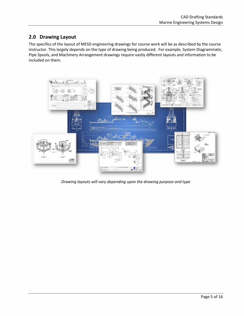
2.0 Drawing Layout The specifics of the layout of MESD engineering drawings for course work will be as described by the course instructor. This largely depends on the type of drawing being produced. For example, System Diagrammatic, Pipe Spools, and Machinery Arrangement drawings require vastly different layouts and information to be included on them.
Drawing layouts will vary depending upon the drawing purpose and type
CAD Drafting Standards Marine Engineering Systems Design
Page 6 of 16
3.0 Drawing Format
3.1 Title Block and Border Standard Formats
The following standard sheets may be used and correspond to the latest MESD Title Block AutoCAD drawing associated with this document. Metric - ISO Paper Sizes
Inches Millimeters
A0 33.1 x 46.8 841 × 1189
Technical Drawings A1 23.4 x 33.1 594 × 841
A2 16.5 x 23.4 420 × 594
A3 11.7 x 16.5 297 × 420 11"x17"
A4 8.3 x 11.7 210 × 297 Letter
Imperial - ANSI Paper Sizes
Inches Millimeters
ANSI A 8.5 x 11 216 x 279 Letter
ANSI B 11 x 17 279 x 432 11"x17"
ANSI C 17 x 22 432 x 559 A2
ANSI D 22 x 34 559 x 864 A1
ANSI E 34 x 44 864 x 1118 A0
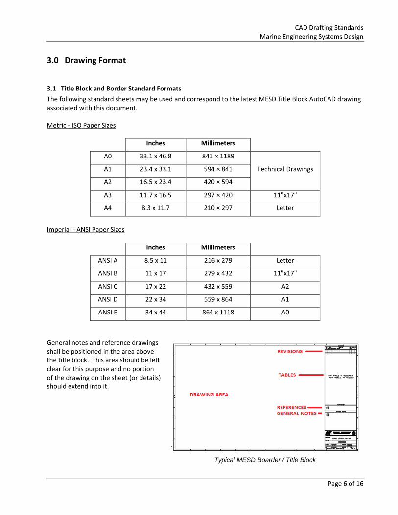
General notes and reference drawings shall be positioned in the area above the title block. This area should be left clear for this purpose and no portion of the drawing on the sheet (or details) should extend into it.
Typical MESD Boarder / Title Block
CAD Drafting Standards Marine Engineering Systems Design
Page 7 of 16
3.2 Text and Leader Lines
All text is to be upper case, ROMANS font, 2.5 mm high for general text and 5.0 mm high for view titles (plan views, sections, elevations, etc.).
A width factor of 1.0 (default) is generally to be used throughout the drawing except where slight compression of the text is required to fit the text on the drawing.
Arrow heads on leader lines are to be solid fill, 2.5 mm long.
Leader lines shall have a short horizontal line next to the text label and the arrow head should touch the object being labelled (but not extend into it).
Multiple line text will be aligned on the left hand side, regardless of which side of the text the leader line is on.
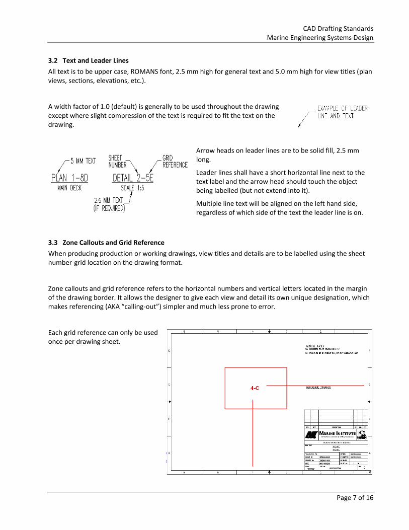
3.3 Zone Callouts and Grid Reference
When producing production or working drawings, view titles and details are to be labelled using the sheet number-grid location on the drawing format.
Zone callouts and grid reference refers to the horizontal numbers and vertical letters located in the margin of the drawing border. It allows the designer to give each view and detail its own unique designation, which makes referencing (AKA “calling-out”) simpler and much less prone to error.
Each grid reference can only be used once per drawing sheet.
CAD Drafting Standards Marine Engineering Systems Design
Page 8 of 16
3.4 Scales
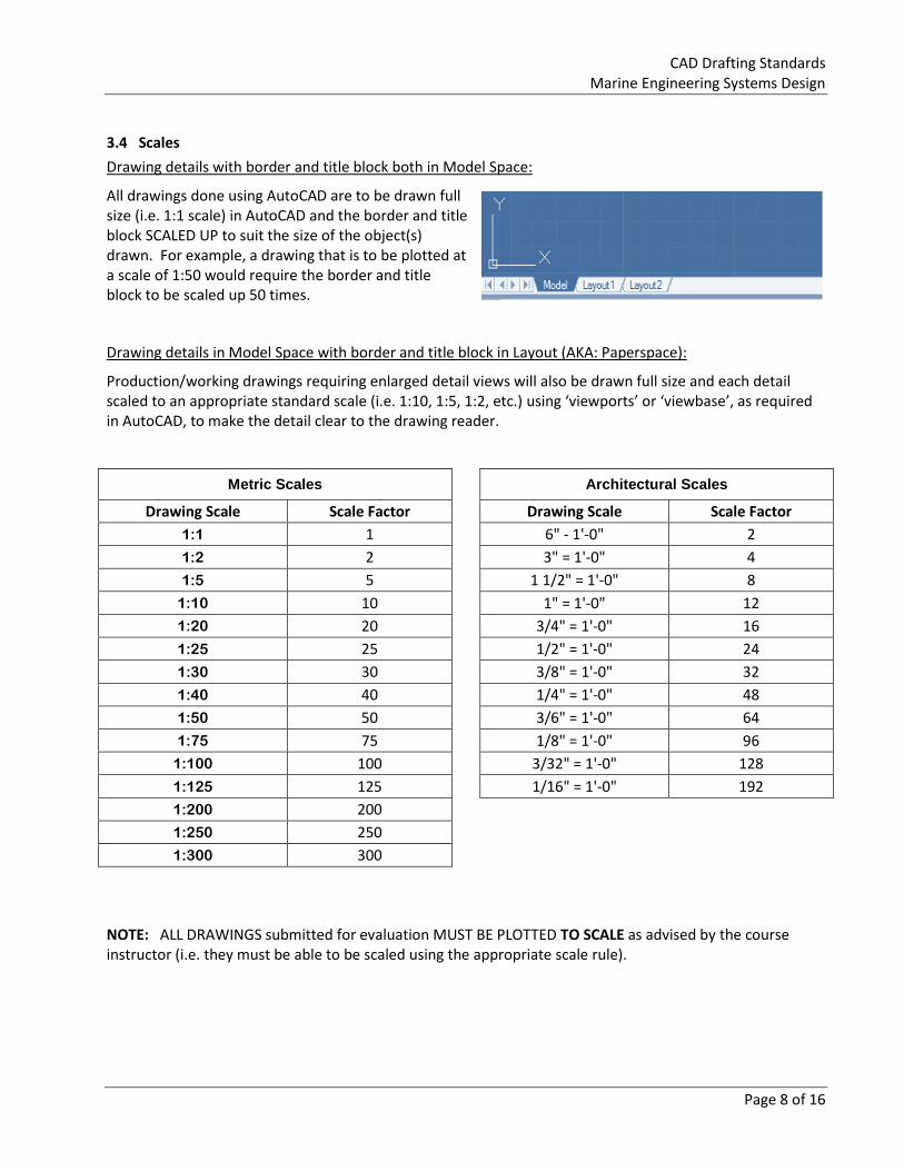
Drawing details with border and title block both in Model Space:
All drawings done using AutoCAD are to be drawn full size (i.e. 1:1 scale) in AutoCAD and the border and title block SCALED UP to suit the size of the object(s) drawn. For example, a drawing that is to be plotted at a scale of 1:50 would require the border and title block to be scaled up 50 times.
Drawing details in Model Space with border and title block in Layout (AKA: Paperspace):
Production/working drawings requiring enlarged detail views will also be drawn full size and each detail scaled to an appropriate standard scale (i.e. 1:10, 1:5, 1:2, etc.) using ‘viewports’ or ‘viewbase’, as required in AutoCAD, to make the detail clear to the drawing reader.
Metric Scales
Architectural Scales
Drawing Scale Scale Factor
Drawing Scale Scale Factor
1:1 1
6" - 1'-0" 2
1:2 2
3" = 1'-0" 4
1:5 5
1 1/2" = 1'-0" 8
1:10 10
1" = 1'-0" 12
1:20 20
3/4" = 1'-0" 16
1:25 25
1/2" = 1'-0" 24
1:30 30
3/8" = 1'-0" 32
1:40 40
1/4" = 1'-0" 48
1:50 50
3/6" = 1'-0" 64
1:75 75
1/8" = 1'-0" 96
1:100 100
3/32" = 1'-0" 128
1:125 125
1/16" = 1'-0" 192
1:200 200
1:250 250
1:300 300
NOTE: ALL DRAWINGS submitted for evaluation MUST BE PLOTTED TO SCALE as advised by the course instructor (i.e. they must be able to be scaled using the appropriate scale rule).
CAD Drafting Standards Marine Engineering Systems Design
Page 9 of 16
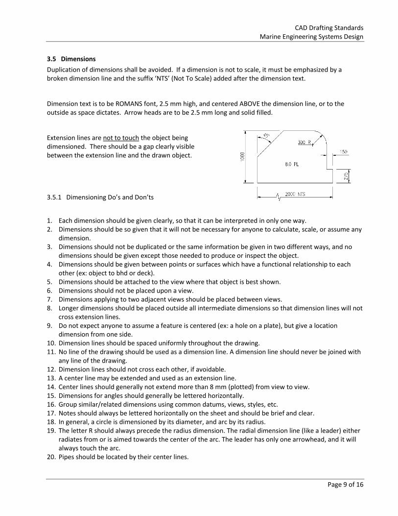
3.5 Dimensions
Duplication of dimensions shall be avoided. If a dimension is not to scale, it must be emphasized by a broken dimension line and the suffix ‘NTS’ (Not To Scale) added after the dimension text.
Dimension text is to be ROMANS font, 2.5 mm high, and centered ABOVE the dimension line, or to the outside as space dictates. Arrow heads are to be 2.5 mm long and solid filled.
Extension lines are not to touch the object being dimensioned. There should be a gap clearly visible between the extension line and the drawn object.
3.5.1 Dimensioning Do’s and Don’ts
1. Each dimension should be given clearly, so that it can be interpreted in only one way. 2. Dimensions should be so given that it will not be necessary for anyone to calculate, scale, or assume any
dimension. 3. Dimensions should not be duplicated or the same information be given in two different ways, and no
dimensions should be given except those needed to produce or inspect the object. 4. Dimensions should be given between points or surfaces which have a functional relationship to each
other (ex: object to bhd or deck). 5. Dimensions should be attached to the view where that object is best shown. 6. Dimensions should not be placed upon a view. 7. Dimensions applying to two adjacent views should be placed between views. 8. Longer dimensions should be placed outside all intermediate dimensions so that dimension lines will not
cross extension lines. 9. Do not expect anyone to assume a feature is centered (ex: a hole on a plate), but give a location
dimension from one side. 10. Dimension lines should be spaced uniformly throughout the drawing. 11. No line of the drawing should be used as a dimension line. A dimension line should never be joined with
any line of the drawing. 12. Dimension lines should not cross each other, if avoidable. 13. A center line may be extended and used as an extension line. 14. Center lines should generally not extend more than 8 mm (plotted) from view to view. 15. Dimensions for angles should generally be lettered horizontally. 16. Group similar/related dimensions using common datums, views, styles, etc. 17. Notes should always be lettered horizontally on the sheet and should be brief and clear. 18. In general, a circle is dimensioned by its diameter, and arc by its radius. 19. The letter R should always precede the radius dimension. The radial dimension line (like a leader) either
radiates from or is aimed towards the center of the arc. The leader has only one arrowhead, and it will always touch the arc.
20. Pipes should be located by their center lines.
CAD Drafting Standards Marine Engineering Systems Design
Page 10 of 16
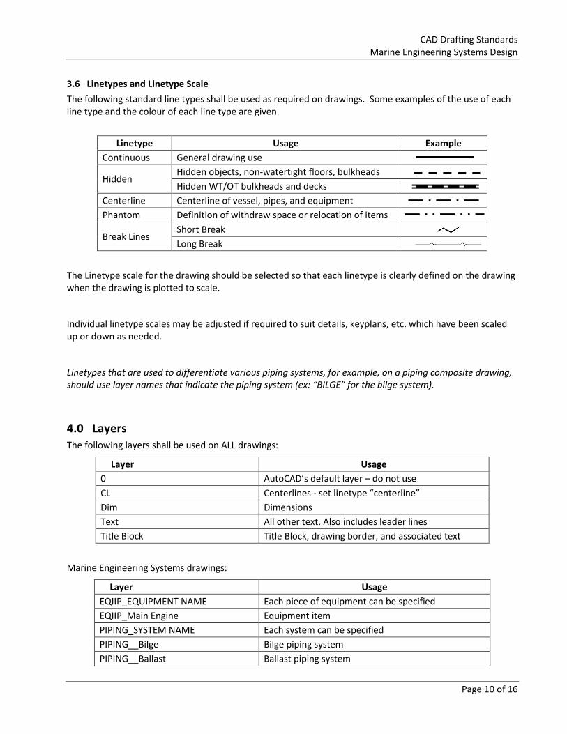
3.6 Linetypes and Linetype Scale
The following standard line types shall be used as required on drawings. Some examples of the use of each line type and the colour of each line type are given.
Linetype Usage Example
Continuous General drawing use
Hidden Hidden objects, non-watertight floors, bulkheads
Hidden WT/OT bulkheads and decks
Centerline Centerline of vessel, pipes, and equipment
Phantom Definition of withdraw space or relocation of items
Break Lines Short Break
Long Break
The Linetype scale for the drawing should be selected so that each linetype is clearly defined on the drawing when the drawing is plotted to scale.
Individual linetype scales may be adjusted if required to suit details, keyplans, etc. which have been scaled up or down as needed.
Linetypes that are used to differentiate various piping systems, for example, on a piping composite drawing, should use layer names that indicate the piping system (ex: “BILGE” for the bilge system).
4.0 Layers The following layers shall be used on ALL drawings:
Layer Usage
0 AutoCAD’s default layer – do not use
CL Centerlines - set linetype “centerline”
Dim Dimensions
Text All other text. Also includes leader lines
Title Block Title Block, drawing border, and associated text
Marine Engineering Systems drawings:
Layer Usage
EQIIP_EQUIPMENT NAME Each piece of equipment can be specified
EQIIP_Main Engine Equipment item
PIPING_SYSTEM NAME Each system can be specified
PIPING__Bilge Bilge piping system
PIPING__Ballast Ballast piping system
CAD Drafting Standards Marine Engineering Systems Design
Page 11 of 16
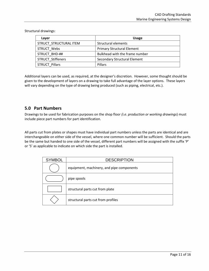
Structural drawings:
Layer Usage
STRUCT_STRUCTURAL ITEM Structural elements
STRUCT_Webs Primary Structural Element
STRUCT_BHD-## Bulkhead with the frame number
STRUCT_Stiffeners Secondary Structural Element
STRUCT_Pillars Pillars
Additional layers can be used, as required, at the designer’s discretion. However, some thought should be given to the development of layers on a drawing to take full advantage of the layer options. These layers will vary depending on the type of drawing being produced (such as piping, electrical, etc.).
5.0 Part Numbers Drawings to be used for fabrication purposes on the shop floor (i.e. production or working drawings) must include piece part numbers for part identification.
All parts cut from plates or shapes must have individual part numbers unless the parts are identical and are interchangeable on either side of the vessel, where one common number will be sufficient. Should the parts be the same but handed to one side of the vessel, different part numbers will be assigned with the suffix ‘P’ or ‘S’ as applicable to indicate on which side the part is installed.
SYMBOL DESCRIPTION
equipment, machinery, and pipe components
pipe spools
structural parts cut from plate
structural parts cut from profiles
CAD Drafting Standards Marine Engineering Systems Design
Page 12 of 16
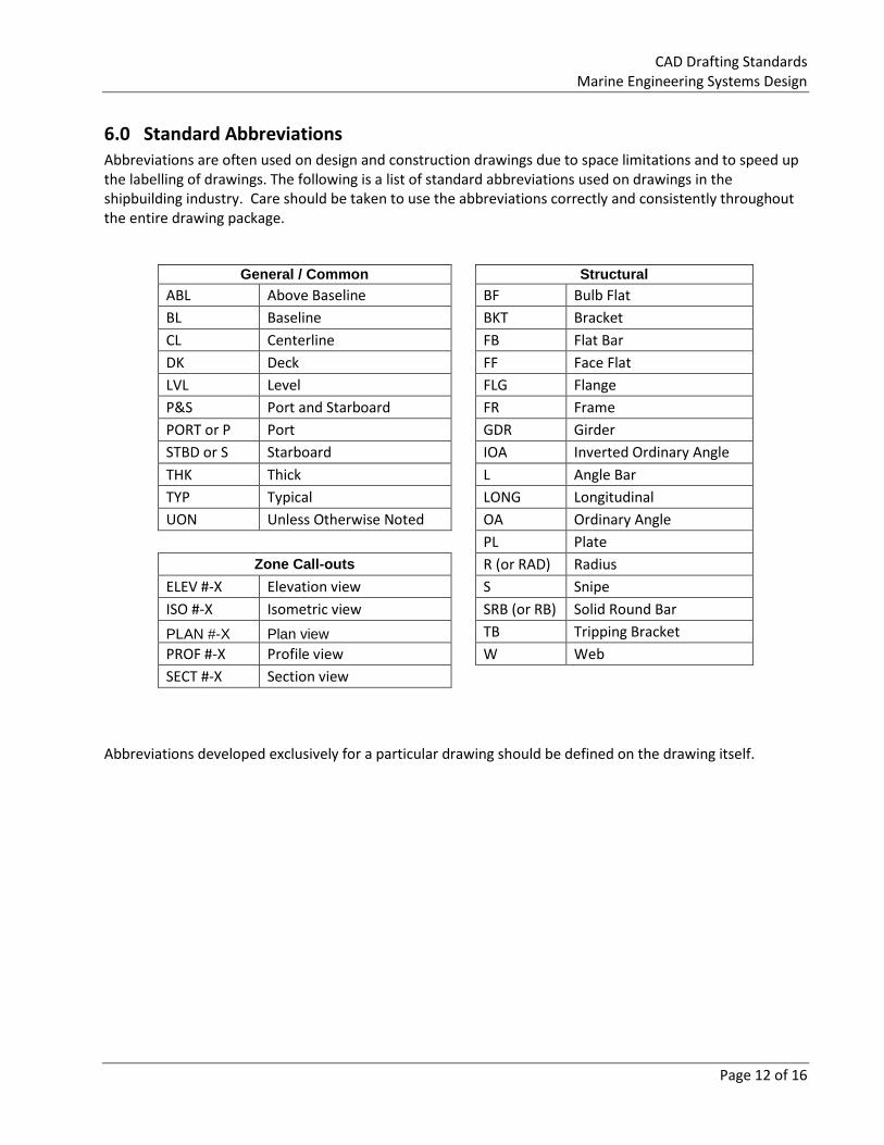
6.0 Standard Abbreviations Abbreviations are often used on design and construction drawings due to space limitations and to speed up the labelling of drawings. The following is a list of standard abbreviations used on drawings in the shipbuilding industry. Care should be taken to use the abbreviations correctly and consistently throughout the entire drawing package.
General / Common
Structural
ABL Above Baseline
BF Bulb Flat
BL Baseline
BKT Bracket
CL Centerline
FB Flat Bar
DK Deck
FF Face Flat
LVL Level
FLG Flange
P&S Port and Starboard
FR Frame
PORT or P Port
GDR Girder
STBD or S Starboard
IOA Inverted Ordinary Angle
THK Thick
L Angle Bar
TYP Typical
LONG Longitudinal
UON Unless Otherwise Noted
OA Ordinary Angle
PL Plate
Zone Call-outs
R (or RAD) Radius
ELEV #-X Elevation view
S Snipe
ISO #-X Isometric view
SRB (or RB) Solid Round Bar
PLAN #-X Plan view
TB Tripping Bracket
PROF #-X Profile view
W Web
SECT #-X Section view
Abbreviations developed exclusively for a particular drawing should be defined on the drawing itself.
CAD Drafting Standards Marine Engineering Systems Design
Page 13 of 16
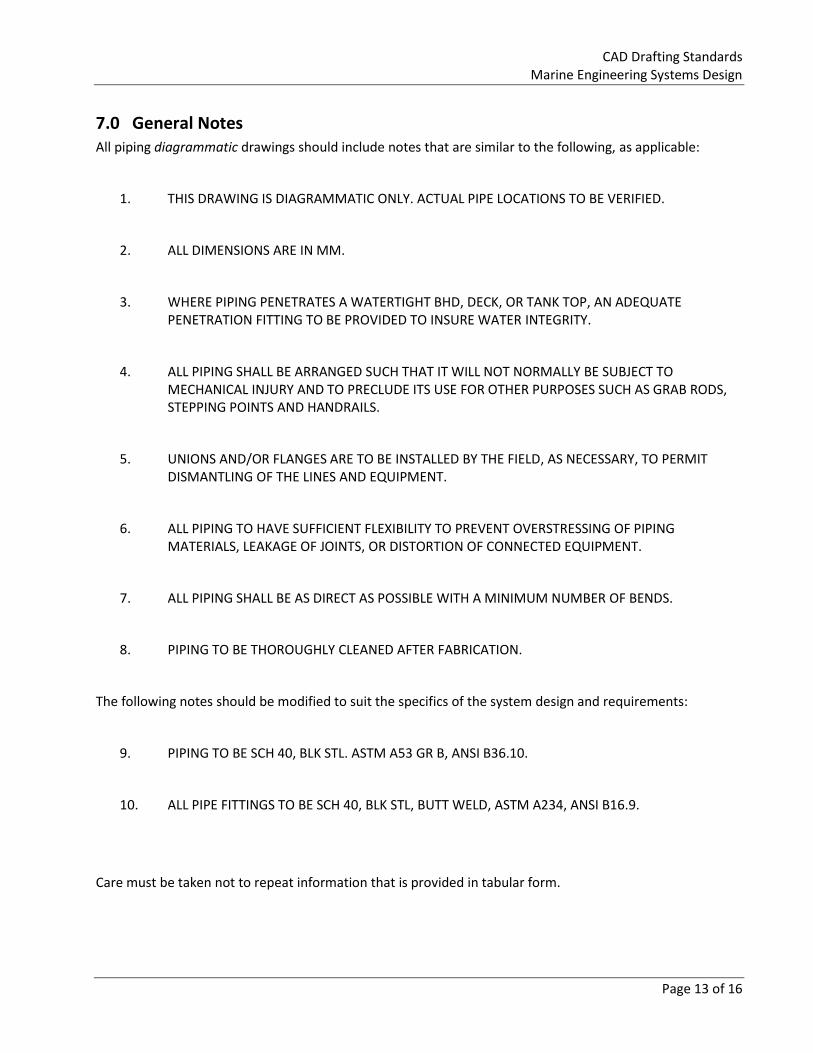
7.0 General Notes All piping diagrammatic drawings should include notes that are similar to the following, as applicable:
1. THIS DRAWING IS DIAGRAMMATIC ONLY. ACTUAL PIPE LOCATIONS TO BE VERIFIED.
2. ALL DIMENSIONS ARE IN MM.
3. WHERE PIPING PENETRATES A WATERTIGHT BHD, DECK, OR TANK TOP, AN ADEQUATE PENETRATION FITTING TO BE PROVIDED TO INSURE WATER INTEGRITY.
4. ALL PIPING SHALL BE ARRANGED SUCH THAT IT WILL NOT NORMALLY BE SUBJECT TO MECHANICAL INJURY AND TO PRECLUDE ITS USE FOR OTHER PURPOSES SUCH AS GRAB RODS, STEPPING POINTS AND HANDRAILS.
5. UNIONS AND/OR FLANGES ARE TO BE INSTALLED BY THE FIELD, AS NECESSARY, TO PERMIT DISMANTLING OF THE LINES AND EQUIPMENT.
6. ALL PIPING TO HAVE SUFFICIENT FLEXIBILITY TO PREVENT OVERSTRESSING OF PIPING MATERIALS, LEAKAGE OF JOINTS, OR DISTORTION OF CONNECTED EQUIPMENT.
7. ALL PIPING SHALL BE AS DIRECT AS POSSIBLE WITH A MINIMUM NUMBER OF BENDS.
8. PIPING TO BE THOROUGHLY CLEANED AFTER FABRICATION.
The following notes should be modified to suit the specifics of the system design and requirements:
9. PIPING TO BE SCH 40, BLK STL. ASTM A53 GR B, ANSI B36.10.
10. ALL PIPE FITTINGS TO BE SCH 40, BLK STL, BUTT WELD, ASTM A234, ANSI B16.9.
Care must be taken not to repeat information that is provided in tabular form.
CAD Drafting Standards Marine Engineering Systems Design
Page 14 of 16
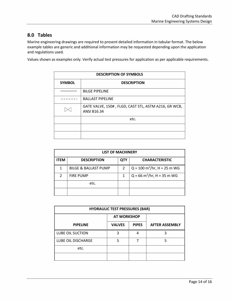
8.0 Tables Marine engineering drawings are required to present detailed information in tabular format. The below example tables are generic and additional information may be requested depending upon the application and regulations used.
Values shown as examples only. Verify actual test pressures for application as per applicable requirements.
DESCRIPTION OF SYMBOLS
SYMBOL DESCRIPTION
BILGE PIPELINE
BALLAST PIPELINE
GATE VALVE, 150# , FLGD, CAST STL, ASTM A216, GR WCB, ANSI B16.34
etc.
LIST OF MACHINERY
ITEM DESCRIPTION QTY CHARACTERISTIC
1 BILGE & BALLAST PUMP 2 Q = 100 m3/hr, H = 25 m WG
2 FIRE PUMP 1 Q = 66 m3/hr, H = 35 m WG
etc.
HYDRAULIC TEST PRESSURES (BAR)
PIPELINE
AT WORKSHOP
AFTER ASSEMBLY VALVES PIPES
LUBE OIL SUCTION 3 4 3
LUBE OIL DISCHARGE 5 7 5
etc.
CAD Drafting Standards Marine Engineering Systems Design
Page 15 of 16
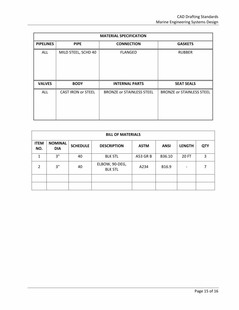
MATERIAL SPECIFICATION
PIPELINES PIPE CONNECTION GASKETS
ALL MILD STEEL, SCHD 40 FLANGED RUBBER
VALVES BODY INTERNAL PARTS SEAT SEALS
ALL CAST IRON or STEEL BRONZE or STAINLESS STEEL BRONZE or STAINLESS STEEL
BILL OF MATERIALS
ITEM NO.
NOMINAL DIA
SCHEDULE DESCRIPTION ASTM ANSI LENGTH QTY
1 3" 40 BLK STL A53 GR B B36.10 20 FT 3
2 3" 40 ELBOW, 90-DEG,
BLK STL A234 B16.9 - 7

CAD Drafting Standards Marine Engineering Systems Design
Page 16 of 16
References
2016, December 14. ISO 128-1:2003. Retrieved from https://www.iso.org/standard/32462.html
ASME Y14.41-2012 - Digital Product Definition Data Practices
Public Services and Procurement Canada, Real Property Branch. (2019, May 23). Public Services and Procurement Canada-National Computer Aided Design and Drafting Standard. Retrieved from https://www.tpsgc-pwgsc.gc.ca/biens-property/cdao-cadd/index-eng.html
Shipyard Drafting Standards of Alabama Shipyard, Avondale Shipyard, C&C Boatworks, Marystown Shipyard and NASSCO