Embed Size (px)
Citation preview
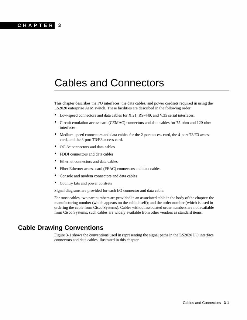
C H A P T E R
3Cables and Connectors
This chapter describes the I/O interfaces, the data cables, and power cordsets required in using theLS2020 enterprise ATM switch. These facilities are described in the following order:
• Low-speed connectors and data cables for X.21, RS-449, and V.35 serial interfaces.
• Circuit emulation access card (CEMAC) connectors and data cables for 75-ohm and 120-ohminterfaces.
• Medium-speed connectors and data cables for the 2-port access card, the 4-port T3/E3 accesscard, and the 8-port T3/E3 access card.
• OC-3c connectors and data cables
• FDDI connectors and data cables
• Ethernet connectors and data cables
• Fiber Ethernet access card (FEAC) connectors and data cables
• Console and modem connectors and data cables
• Country kits and power cordsets
Signal diagrams are provided for each I/O connector and data cable.
For most cables, two part numbers are provided in an associated table in the body of the chapter: themanufacturing number (which appears on the cable itself); and the order number (which is used inordering the cable from Cisco Systems). Cables without associated order numbers are not availablefrom Cisco Systems; such cables are widely available from other vendors as standard items.
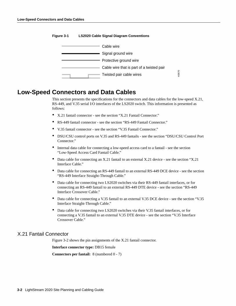
Cable Drawing ConventionsFigure 3-1 shows the conventions used in representing the signal paths in the LS2020 I/O interfaceconnectors and data cables illustrated in this chapter.
Cables and Connectors 3-1
Low-Speed Connectors and Data Cables
Figure 3-1 LS2020 Cable Signal Diagram Conventions
Low-Speed Connectors and Data CablesThis section presents the specifications for the connectors and data cables for the low-speed X.21,RS-449, and V.35 serial I/O interfaces of the LS2020 switch. This information is presented asfollows:
• X.21 fantail connector - see the section “X.21 Fantail Connector.”
• RS-449 fantail connector - see the section “RS-449 Fantail Connector.”
• V.35 fantail connector - see the section “V.35 Fantail Connector.”
• DSU/CSU control ports on V.35 and RS-449 fantails - see the section “DSU/CSU Control PortConnector.”
• Internal data cable for connecting a low-speed access card to a fantail - see the section“Low-Speed Access Card Fantail Cable.”
• Data cable for connecting an X.21 fantail to an external X.21 device - see the section “X.21Interface Cable.”
• Data cable for connecting an RS-449 fantail to an external RS-449 DCE device - see the section“RS-449 Interface Straight-Through Cable.”
• Data cable for connecting two LS2020 switches via their RS-449 fantail interfaces, or forconnecting an RS-449 fantail to an external RS-449 DTE device - see the section “RS-449Interface Crossover Cable.”
• Data cable for connecting a V.35 fantail to an external V.35 DCE device - see the section “V.35Interface Straight-Through Cable.”
• Data cable for connecting two LS2020 switches via their V.35 fantail interfaces, or forconnecting a V.35 fantail to an external V.35 DTE device - see the section “V.35 InterfaceCrossover Cable.”
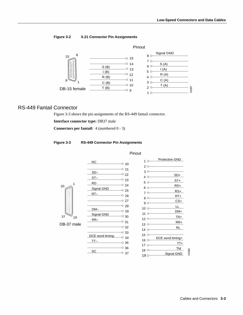
X.21 Fantail ConnectorFigure 3-2 shows the pin assignments of the X.21 fantail connector.
Interface connector type:DB15 female
Connectors per fantail: 8 (numbered 0 - 7)
Cable wire
Signal ground wire
Protective ground wire
Cable wire that is part of a twisted pair
Twisted pair cable wires H3
67
0
3-2 LightStream 2020 Site Planning and Cabling Guide
Low-Speed Connectors and Data Cables
Figure 3-2 X.21 Connector Pin Assignments
RS-449 Fantail ConnectorFigure 3-3 shows the pin assignments of the RS-449 fantail connector.
Interface connector type:DB37 male
Connectors per fantail: 4 (numbered 0 - 3)
Figure 3-3 RS-449 Connector Pin Assignments
Pinout
8
7
6
5
4
3
2
1
14
13
12
11
10
9
C (B)
I (B)
T (B)
S (B)
DB-15 female
H33
87
R (B)
T (A)
C (A)
R (A)
I (A)
S (A)
Signal GND
1
8
9
15 15
Pinout
1
2
3
4SD+
Protective GND
5
6
7
8
RS+
RT+
RD+
9
10
11
12
DM+
TR+
LL
13
14
15
16DCE send timing+
RL
17
18
19
TM
Signal GND
TT+
20
21
22
23
24
25
26
27
28
29
30
31
32
33
34
35
36
37
SD–
ST–
RT–
RR–
DM–
TT–
SC
ST+
RR+
RC
RD
Signal GND
Signal GND
DCE send timing-
H33
88
DB-37 male
1
19
20
37
CS+
Cables and Connectors 3-3
Low-Speed Connectors and Data Cables
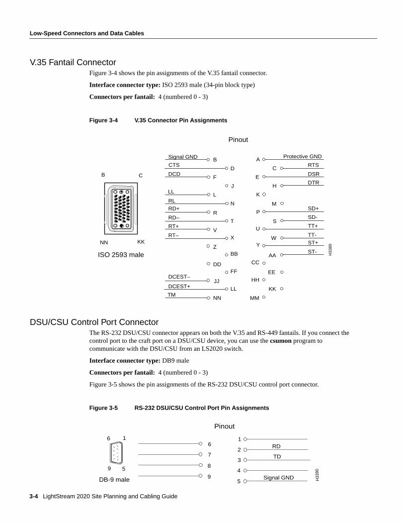
V.35 Fantail ConnectorFigure 3-4 shows the pin assignments of the V.35 fantail connector.
Interface connector type:ISO 2593 male (34-pin block type)
Connectors per fantail: 4 (numbered 0 - 3)
Figure 3-4 V.35 Connector Pin Assignments
DSU/CSU Control Port ConnectorThe RS-232 DSU/CSU connector appears on both the V.35 and RS-449 fantails. If you connect thecontrol port to the craft port on a DSU/CSU device, you can use thecsumon program tocommunicate with the DSU/CSU from an LS2020 switch.
Interface connector type:DB9 male
Connectors per fantail: 4 (numbered 0 - 3)
Figure 3-5 shows the pin assignments of the RS-232 DSU/CSU control port connector.
Figure 3-5 RS-232 DSU/CSU Control Port Pin Assignments
Pinout
B
D
F
J
L
N
R
T
LL
RT+
DCEST–
DCD
Signal GND
RD+
RD–
RL
RT–V
X
Z
DD
JJLL
NN
DCEST+
TM
BB
FF
A
C
E
H
K
M
P
DSR
DTR
RTS
SU
W
AA
EEHH
KK
Y
CC
MM
SD+
SD-
TT+
TT-ST+
ST-
Protective GND
H33
89
ISO 2593 male
B
NN
C
KK
CTS
Pinout
1
2
3
4
5
6
7
8
9 Signal GND
RD
TD
H33
90
DB-9 male
1
5
6
9
3-4 LightStream 2020 Site Planning and Cabling Guide
Low-Speed Connectors and Data Cables
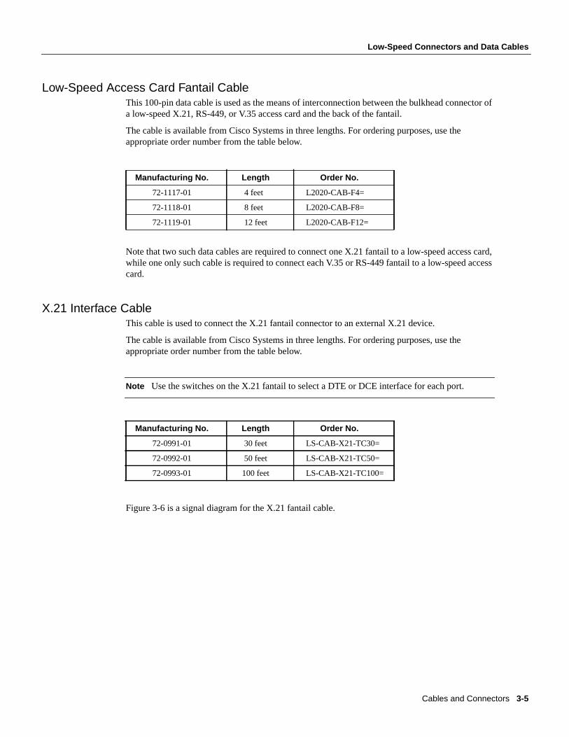
Low-Speed Access Card Fantail CableThis 100-pin data cable is used as the means of interconnection between the bulkhead connector ofa low-speed X.21, RS-449, or V.35 access card and the back of the fantail.
The cable is available from Cisco Systems in three lengths. For ordering purposes, use theappropriate order number from the table below.
Note that two such data cables are required to connect one X.21 fantail to a low-speed access card,while one only such cable is required to connect each V.35 or RS-449 fantail to a low-speed accesscard.
X.21 Interface CableThis cable is used to connect the X.21 fantail connector to an external X.21 device.
The cable is available from Cisco Systems in three lengths. For ordering purposes, use theappropriate order number from the table below.
Note Use the switches on the X.21 fantail to select a DTE or DCE interface for each port.
Figure 3-6 is a signal diagram for the X.21 fantail cable.
Manufacturing No. Length Order No.
72-1117-01 4 feet L2020-CAB-F4=
72-1118-01 8 feet L2020-CAB-F8=
72-1119-01 12 feet L2020-CAB-F12=
Manufacturing No. Length Order No.
72-0991-01 30 feet LS-CAB-X21-TC30=
72-0992-01 50 feet LS-CAB-X21-TC50=
72-0993-01 100 feet LS-CAB-X21-TC100=
Cables and Connectors 3-5

Low-Speed Connectors and Data Cables
Figure 3-6 X.21 Cable Signal Diagram
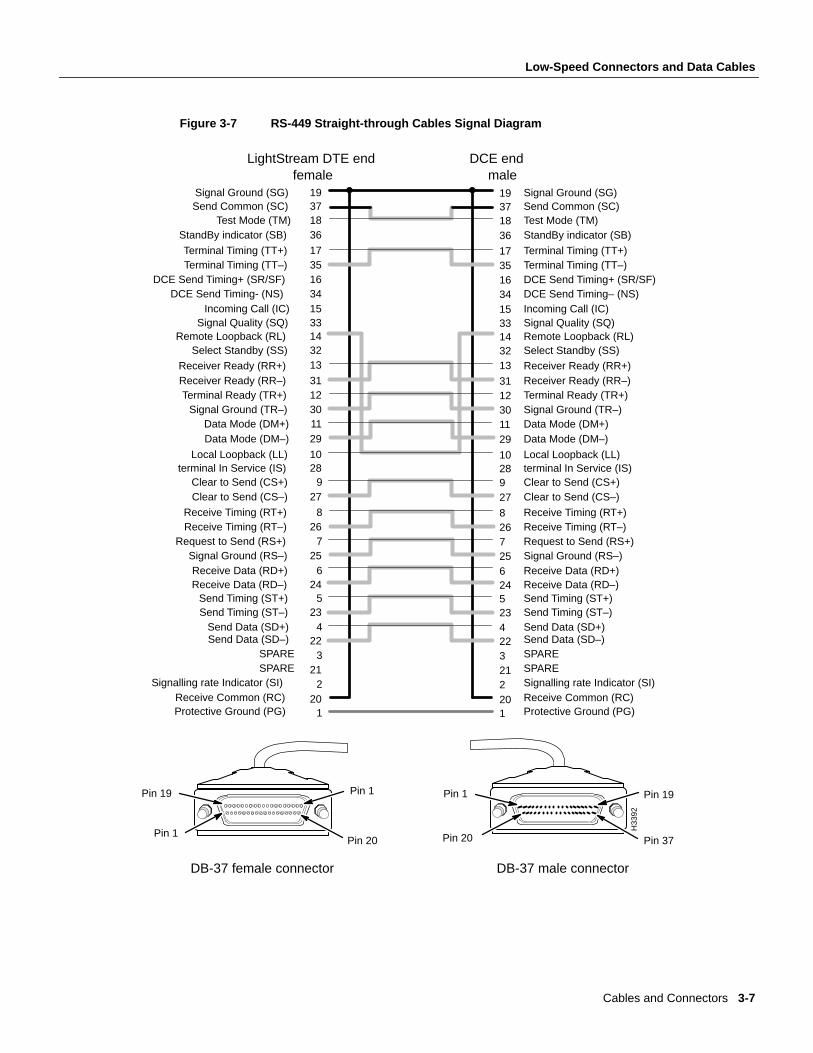
RS-449 Interface Straight-Through CableThis cable is used to connect an RS-449 fantail interface to an external RS-449 DCE device.
This cable is available from Cisco Systems. For ordering purposes, use the appropriate order numberfrom the table below.
Figure 3-7 is a signal diagram for the RS-449 fantail straight-through cable.
Manufacturing No. Length Order No.
72-1002-01 30 feet LS-CAB-RS4-TC30=
72-1003-01 50 feet LS-CAB-RS4-TC50=
72-1004-01 100 feet LS-CAB-RS4-TC100=
611492Transmit (T(A))
Receive (R(B))Signal element timing (S(A))
Receive (R(A))Transmit (T(B))
103
13
Control (C(A))
Signal element timing (S(B))
Control (C(B))
611492
103
13
Transmit (T(A))
Receive (R(B))Signal element timing (S(A))
Receive (R(A))Transmit (T(B))
Control (C(A))
Signal element timing (S(B))
Control (C(B))
DTE end DCE endfemale male
DB-15 female connector
Pin 1
Pin 9
Pin 8
Pin 15
Pin 1
Pin 9
Pin 8
Pin 15
DB-15 male connector
5Indication (I(A))12Indication (I(B))
512
Indication (I(A))Indication (I(B))
1Protective GND 1 Protective GND
8Signal GND 8 Signal GND
H3
39
1
3-6 LightStream 2020 Site Planning and Cabling Guide
Low-Speed Connectors and Data Cables
Figure 3-7 RS-449 Straight-through Cables Signal Diagram
1534163517
36183719
LightStream DTE end DCE end
Terminal Timing (TT+)
Send Common (SC)Signal Ground (SG)
StandBy indicator (SB)Test Mode (TM)
DCE Send Timing- (NS)Incoming Call (IC)
DCE Send Timing+ (SR/SF)Terminal Timing (TT–)
2911301231
13321433
Receiver Ready (RR–)
Remote Loopback (RL)Signal Quality (SQ)
Receiver Ready (RR+)
Select Standby (SS)
Data Mode (DM+)Data Mode (DM–)
Signal Ground (TR–)Terminal Ready (TR+)
625
726
8
279
2810
Receive Timing (RT+)
terminal In Service (IS)Local Loopback (LL)
Clear to Send (CS–)Clear to Send (CS+)
Signal Ground (RS–)Receive Data (RD+)
Request to Send (RS+)Receive Timing (RT–)
202
213
224
235
24
Send Data (SD–)
Send Timing (ST+)Receive Data (RD–)
Send Data (SD+)Send Timing (ST–)
Signalling rate Indicator (SI)SPARESPARE
Receive Common (RC)
1Protective Ground (PG)
1534163517
36183719
2911301231
13321433
6257268
2792810
20221322423524
1
Terminal Timing (TT+)
Send Common (SC)Signal Ground (SG)
StandBy indicator (SB)Test Mode (TM)
DCE Send Timing– (NS)Incoming Call (IC)
DCE Send Timing+ (SR/SF)Terminal Timing (TT–)
Receiver Ready (RR–)
Remote Loopback (RL)Signal Quality (SQ)
Receiver Ready (RR+)
Select Standby (SS)
Data Mode (DM+)Data Mode (DM–)
Signal Ground (TR–)Terminal Ready (TR+)
Receive Timing (RT+)
terminal In Service (IS)Local Loopback (LL)
Clear to Send (CS–)Clear to Send (CS+)
Signal Ground (RS–)Receive Data (RD+)
Request to Send (RS+)Receive Timing (RT–)
Send Data (SD–)
Send Timing (ST+)Receive Data (RD–)
Send Data (SD+)Send Timing (ST–)
Signalling rate Indicator (SI)SPARESPARE
Receive Common (RC)Protective Ground (PG)
DB-37 female connector DB-37 male connector
Pin 1
Pin 20
Pin 19
Pin 1
Pin 1
Pin 20
Pin 19
Pin 37
female male
H33
92
Cables and Connectors 3-7
Low-Speed Connectors and Data Cables
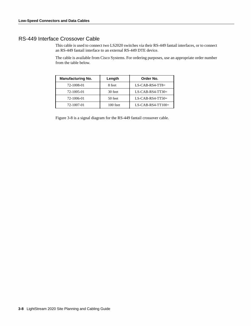
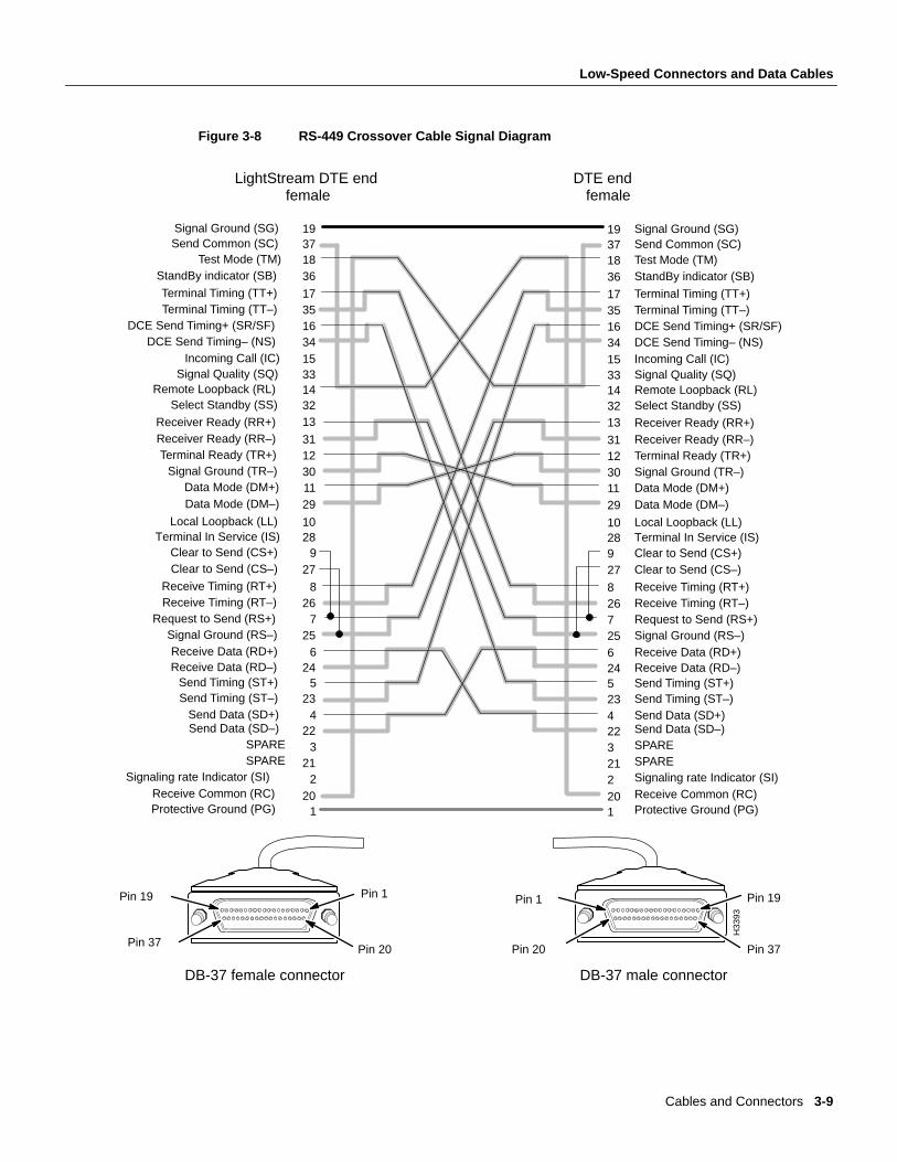
RS-449 Interface Crossover CableThis cable is used to connect two LS2020 switches via their RS-449 fantail interfaces, or to connectan RS-449 fantail interface to an external RS-449 DTE device.
The cable is available from Cisco Systems. For ordering purposes, use an appropriate order numberfrom the table below.
Figure 3-8 is a signal diagram for the RS-449 fantail crossover cable.
Manufacturing No. Length Order No.
72-1008-01 8 feet LS-CAB-RS4-TT8=
72-1005-01 30 feet LS-CAB-RS4-TT30=
72-1006-01 50 feet LS-CAB-RS4-TT50=
72-1007-01 100 feet LS-CAB-RS4-TT100=
3-8 LightStream 2020 Site Planning and Cabling Guide
Low-Speed Connectors and Data Cables
Figure 3-8 RS-449 Crossover Cable Signal Diagram
1534163517
36183719
LightStream DTE end DTE end
Terminal Timing (TT+)
Send Common (SC)Signal Ground (SG)
StandBy indicator (SB)Test Mode (TM)
DCE Send Timing– (NS)Incoming Call (IC)
DCE Send Timing+ (SR/SF)Terminal Timing (TT–)
2911301231
13321433
Receiver Ready (RR–)
Remote Loopback (RL)Signal Quality (SQ)
Receiver Ready (RR+)
Select Standby (SS)
Data Mode (DM+)Data Mode (DM–)
Signal Ground (TR–)Terminal Ready (TR+)
625
726
8
279
2810
Receive Timing (RT+)
Terminal In Service (IS)Local Loopback (LL)
Clear to Send (CS–)Clear to Send (CS+)
Signal Ground (RS–)Receive Data (RD+)
Request to Send (RS+)Receive Timing (RT–)
202
213
224
235
24
Send Data (SD–)
Send Timing (ST+)Receive Data (RD–)
Send Data (SD+)Send Timing (ST–)
Signaling rate Indicator (SI)SPARESPARE
Receive Common (RC)
1Protective Ground (PG)
1534163517
36183719
2911301231
13321433
6257268
2792810
20221322423524
1
Terminal Timing (TT+)
Send Common (SC)Signal Ground (SG)
StandBy indicator (SB)Test Mode (TM)
DCE Send Timing– (NS)Incoming Call (IC)
DCE Send Timing+ (SR/SF)Terminal Timing (TT–)
Receiver Ready (RR–)
Remote Loopback (RL)Signal Quality (SQ)
Receiver Ready (RR+)
Select Standby (SS)
Data Mode (DM+)Data Mode (DM–)
Signal Ground (TR–)Terminal Ready (TR+)
Receive Timing (RT+)
Terminal In Service (IS)Local Loopback (LL)
Clear to Send (CS–)Clear to Send (CS+)
Signal Ground (RS–)Receive Data (RD+)
Request to Send (RS+)Receive Timing (RT–)
Send Data (SD–)
Send Timing (ST+)Receive Data (RD–)
Send Data (SD+)Send Timing (ST–)
Signaling rate Indicator (SI)SPARESPARE
Receive Common (RC)Protective Ground (PG)
DB-37 female connector DB-37 male connector
Pin 1
Pin 20
Pin 19
Pin 37
Pin 1
Pin 20
Pin 19
Pin 37
female female
H33
93
Cables and Connectors 3-9
Low-Speed Connectors and Data Cables
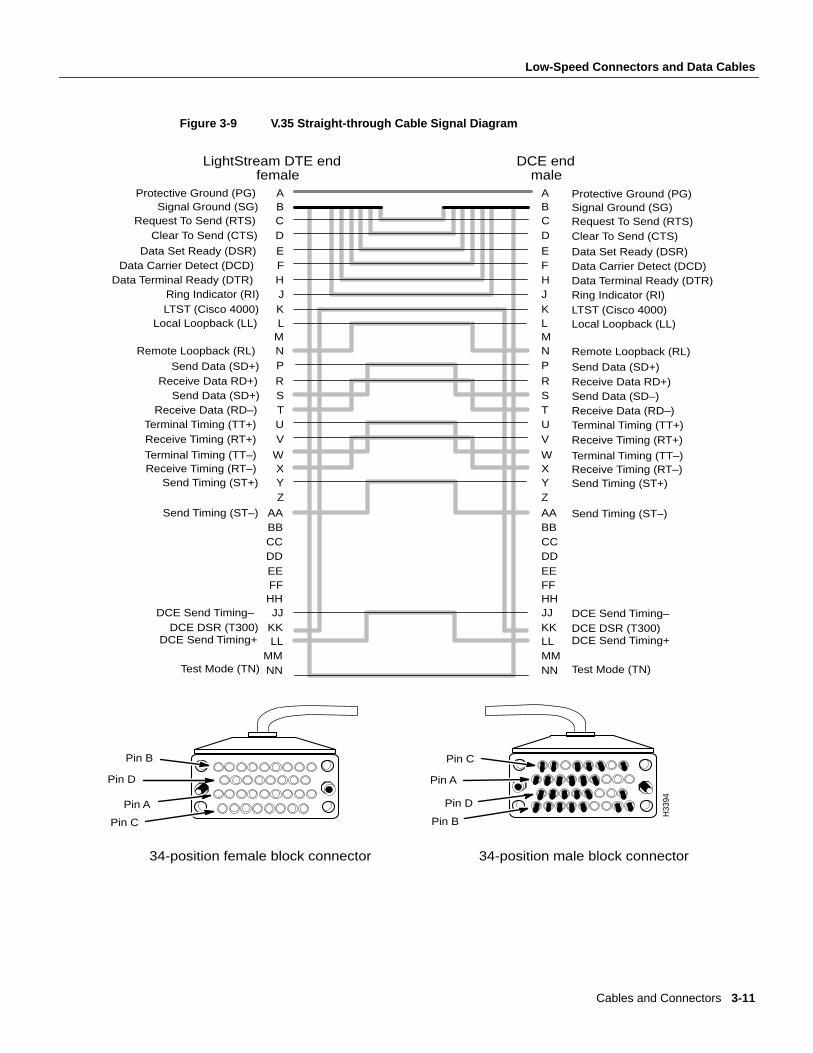
V.35 Interface Straight-Through CableThis cable is used to connect a V.35 fantail interface to an external V.35 DCE device.
The cable is available from Cisco Systems. For ordering purposes, use an appropriate order numberfrom the table below.
Figure 3-9 is a signal diagram for the V.35 fantail straight-through cable.
Manufacturing No. Length Order No.
72-1009-01 30 feet LS-CAB-V35-TC30=
72-1010-01 50 feet LS-CAB-V35-TC50=
72-1011-01 100 feet LS-CAB-V35-TC100=
3-10 LightStream 2020 Site Planning and Cabling Guide
Low-Speed Connectors and Data Cables
Figure 3-9 V.35 Straight-through Cable Signal Diagram
KJHFE
DCBA
Data Set Ready (DSR)
Signal Ground (SG)Protective Ground (PG)
Clear To Send (CTS)Request To Send (RTS)
Ring Indicator (RI)LTST (Cisco 4000)
Data Terminal Ready (DTR)Data Carrier Detect (DCD)
VUTSR
PNML
Receive Data RD+)
Local Loopback (LL)
Send Data (SD+)
Remote Loopback (RL)
Terminal Timing (TT+)Receive Timing (RT+)
Receive Data (RD–)Send Data (SD+)
EEDDCCBBAA
ZYX
W
Send Timing (ST–)
Receive Timing (RT–)Terminal Timing (TT–)
Send Timing (ST+)
NNMM
LLKKJJ
HHFF
DCE Send Timing+DCE DSR (T300)
DCE Send Timing–
Test Mode (TN)
KJHFE
DCBA
VUTSR
PNML
EEDDCCBBAA
ZYXW
NNMMLLKKJJHHFF
Data Set Ready (DSR)
Signal Ground (SG)Protective Ground (PG)
Clear To Send (CTS)Request To Send (RTS)
Ring Indicator (RI)LTST (Cisco 4000)
Data Terminal Ready (DTR)Data Carrier Detect (DCD)
Receive Data RD+)
Local Loopback (LL)
Send Data (SD+)
Remote Loopback (RL)
Terminal Timing (TT+)Receive Timing (RT+)
Receive Data (RD–)Send Data (SD–)
Send Timing (ST–)
Receive Timing (RT–)Terminal Timing (TT–)
Send Timing (ST+)
DCE Send Timing+DCE DSR (T300)DCE Send Timing–
Test Mode (TN)
Pin C
Pin D
Pin A
Pin B Pin C
Pin D
Pin A
Pin B
34-position female block connector 34-position male block connector
LightStream DTE end DCE end female male
H33
94
Cables and Connectors 3-11
Low-Speed Connectors and Data Cables
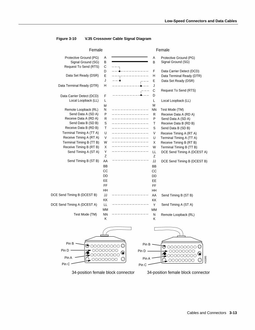
V.35 Interface Crossover CableThis cable is used to connect two LS2020 switches via their V.35 fantail interfaces, or to connect aV.35 fantail to an external V.35 DTE device.
This cable is available from Cisco Systems. For ordering purposes, use the appropriate order numberfrom the table below.
Figure 3-10 is a signal diagram for the V.35 fantail crossover cable.
Manufacturing No. Length Order No.
72-0997-01 8 feet LS-CAB-V35-TT8=
72-0994-01 30 feet LS-CAB-V35-TT30=
72-0995-01 50 feet LS-CAB-V35-TT50=
72-0996-01 100 feet LS-CAB-V35-TT100=
3-12 LightStream 2020 Site Planning and Cabling Guide
Low-Speed Connectors and Data Cables
Figure 3-10 V.35 Crossover Cable Signal Diagram
M
LF
H
JEDCBA
YXWVU
TSRPN
Receive Data A (RD A)
Data Terminal Ready (DTR)
Terminal Timing A (TT A)
Send Timing A (ST A)
Data Carrier Detect (DCD)
Data Set Ready (DSR)
Request To Send (RTS)
Receive Data B (RD B)Send Data A (SD A)
ZAA
BBCCDDEEFFHHJJKKLL
MMNN
L
DC
JE
HF
BA
LLWXUV
STPR
NNM
ZJJ
BBCCDDEEFFHHAAKKY
MMN
Send Data B (SD B)
Receive Timing B (RT B)
DCE Send Timing B (DCEST B)
Remote Loopback (RL)
Data Terminal Ready (DTR)
Data Carrier Detect (DCD)
Terminal Timing A (TT A)
Send Timing B (ST B)
Signal Ground (SG)
Data Set Ready (DSR)
Request To Send (RTS)
Receive Data A (RD A)Send Data A (SD A)
Receive Data B (RD B)Send Data B (SD B)
Receive Timing B (RT B)Send Timing A (ST A)
Terminal Timing B (TT B)Terminal Timing B (TT B)
Receive Timing A (RT A)Receive Timing A (RT A)
Local Loopback (LL)
KK
DCE Send Timing A (DCEST A)
Send Timing B (ST B)DCE Send Timing B (DCEST B)
Test Mode (TM)
DCE Send Timing A (DCEST A)
Pin C
Pin D
Pin A
Pin B
Pin C
Pin D
Pin A
Pin B
34-position female block connector 34-position female block connector
Protective Ground (PG) Protective Ground (PG)
Local Loopback (LL)
Test Mode (TM)Remote Loopback (RL)
Female Female
H3
39
5
Signal Ground (SG)
Cables and Connectors 3-13

Circuit Emulation Access Card (CEMAC) Connectors and Cables
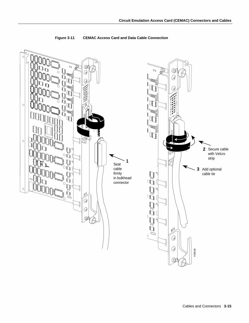
Circuit Emulation Access Card (CEMAC) Connectors and CablesFigure 3-11 shows the CEMAC card and its associated data cable. To make a more secureconnection, unscrew the top mounting screw (shown as “1” in the figure) in the connector retentionbracket and reposition it in the connector (as shown by “2” in the figure). Next, tighten down themounting screw to attach the data cable to the CEMAC card securely (as shown by “3” in the figure).Finally, secure the cable to the CEMAC bulkhead connector with the Velcro strip.
3-14 LightStream 2020 Site Planning and Cabling Guide
Circuit Emulation Access Card (CEMAC) Connectors and Cables
Figure 3-11 CEMAC Access Card and Data Cable Connection
E2
E6
E10
E14
75
120
75
120
75
120
75
120
75
120
75
120
75
120
75
120
E1
8E
22
E2
6E
30
GND
E1
C21
E17
U1
E1
CEMAC
2
E2
E6
E10
E14
75
12
0
75
12
0
75
12
0
75
12
07
5
12
0
75
12
0
75
12
0
75
12
0E
18
E2
2E
26
E3
0
GND
E1
C21
E17
U1
E1
CEMAC
H3618
1
Secure cable with Velcrostrip
Add optionalcable tie
Seatcablefirmlyin bulkheadconnector
3
Cables and Connectors 3-15
Circuit Emulation Access Card (CEMAC) Connectors and Cables
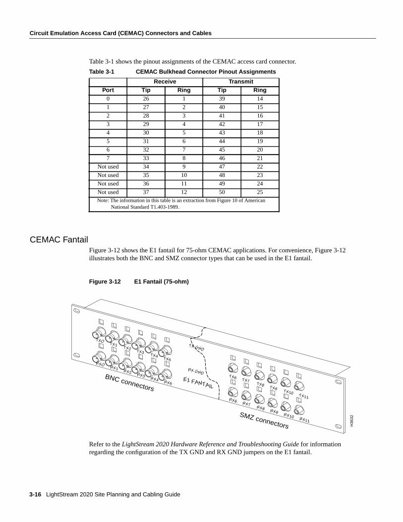
Table 3-1 shows the pinout assignments of the CEMAC access card connector.
CEMAC FantailFigure 3-12 shows the E1 fantail for 75-ohm CEMAC applications. For convenience, Figure 3-12illustrates both the BNC and SMZ connector types that can be used in the E1 fantail.
Figure 3-12 E1 Fantail (75-ohm)
Refer to theLightStream 2020 Hardware Reference and Troubleshooting Guidefor informationregarding the configuration of the TX GND and RX GND jumpers on the E1 fantail.
Table 3-1 CEMAC Bulkhead Connector Pinout Assignments
Receive TransmitPort Tip Ring Tip Ring
0 26 1 39 14
1 27 2 40 15
2 28 3 41 16
3 29 4 42 17
4 30 5 43 18
5 31 6 44 19
6 32 7 45 20
7 33 8 46 21
Not used 34 9 47 22
Not used 35 10 48 23
Not used 36 11 49 24
Not used 37 12 50 25Note: The information in this table is an extraction from Figure 10 of American
National Standard T1.403-1989.
H36
32
RXO RX1
TXO TX1
RX2 RX3
TX2 TX3
RX4 RX5
TX4 TX5
RX6 RX7
TX6 TX7
RX8 RX9
TX8 TX9
RX10 RX11
TX10 TX11
E1 FANTAIL
RX GND
TX GND
BNC connectors
SMZ connectors
3-16 LightStream 2020 Site Planning and Cabling Guide
Medium Speed Connectors and Cables
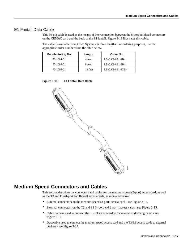
E1 Fantail Data CableThis 50-pin cable is used as the means of interconnection between the 8-port bulkhead connectorson the CEMAC card and the back of the E1 fantail. Figure 3-13 illustrates this cable.
The cable is available from Cisco Systems in three lengths. For ordering purposes, use theappropriate order number from the table below.
Figure 3-13 E1 Fantail Data Cable
Medium Speed Connectors and CablesThis section describes the connectors and cables for the medium-speed (2-port) access card, as wellas the T3 and E3 (4-port and 8-port) access cards, as indicated below:
• External connectors on the medium-speed (2-port) access card - see Figure 3-14.
• External connectors on the T3 and E3 (4-port and 8-port) access cards - see Figure 3-15.
• Cable harness used to connect the T3/E3 access card to its associated dressing panel - seeFigure 3-16.
• Data cable used to connect the medium speed access card and the T3/E3 access cards to externaldevices - see Figure 3-17.
Manufacturing No. Length Order No.
72-1094-01 4 feet LS-CAB-8E1-4B=
72-1095-01 8 feet LS-CAB-8E1-8B=
72-1096-01 12 feet LS-CAB-8E1-12B=
H36
51
Cables and Connectors 3-17
Medium Speed Connectors and Cables
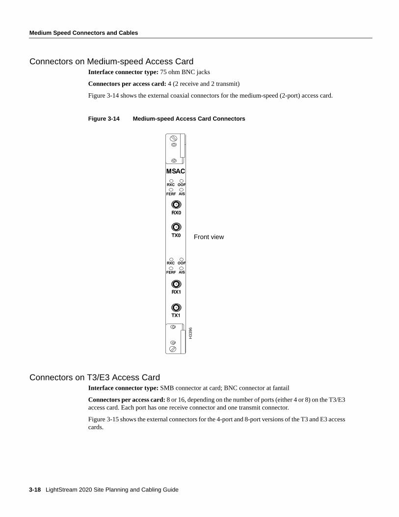
Connectors on Medium-speed Access CardInterface connector type: 75 ohm BNC jacks
Connectors per access card:4 (2 receive and 2 transmit)
Figure 3-14 shows the external coaxial connectors for the medium-speed (2-port) access card.
Figure 3-14 Medium-speed Access Card Connectors
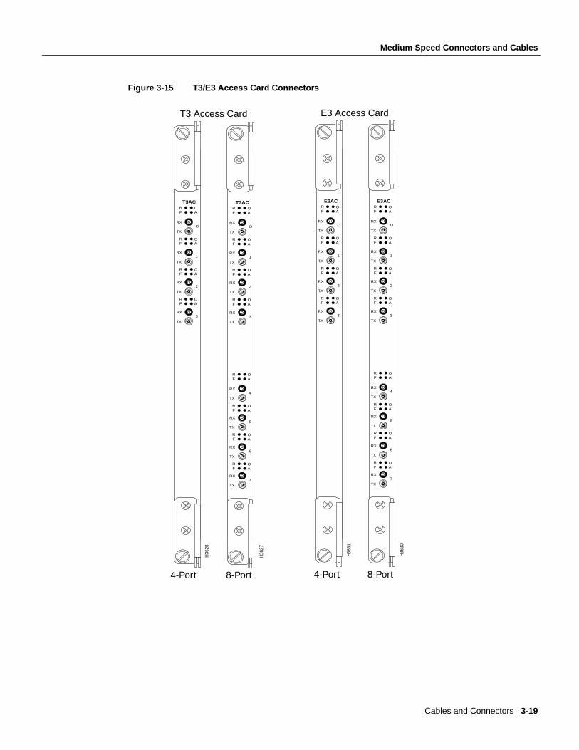
Connectors on T3/E3 Access CardInterface connector type:SMB connector at card; BNC connector at fantail
Connectors per access card:8 or 16, depending on the number of ports (either 4 or 8) on the T3/E3access card. Each port has one receive connector and one transmit connector.
Figure 3-15 shows the external connectors for the 4-port and 8-port versions of the T3 and E3 accesscards.
Front view
H33
96
3-18 LightStream 2020 Site Planning and Cabling Guide
Medium Speed Connectors and Cables
Figure 3-15 T3/E3 Access Card Connectors
T3 Access Card E3 Access Card
4-Port 4-Port8-Port 8-Port
H36
28
RX
T3AC
TX
F AR O
F AR O
O
RX
TX
F AR O
1
RX
TX
F AR O
2
RX
TX
3
H36
27
RX
T3AC
TX
F AR O
F AR O
O
RX
TX
F AR O
1
RX
TX
F AR O
2
RX
TX
F AR O
3
RX
TX
F AR O
4
RX
TX
F AR O
5
RX
TX
F AR O
6
RX
TX
7
H36
30
RX
E3AC
TX
F AR O
F AR O
O
RX
TX
F AR O
1
RX
TX
F AR O
2
RX
TX
F AR O
3
RX
TX
F AR O
4
RX
TX
F AR O
5
RX
TX
F AR O
6
RX
TX
7
H36
31
RX
E3AC
TX
F AR O
F AR O
O
RX
TX
F AR O
1
RX
TX
F AR O
2
RX
TX
3
Cables and Connectors 3-19
Medium Speed Connectors and Cables
T3/E3 Fantail Cable Harness and Dressing PanelTo interconnect patch panel/fantails to T3/E3 access cards, both 4-port and 8-port coaxial cableharnesses are offered by Cisco Systems. In addition, both the 4-port and 8-port harnesses areavailable in 4-, 8-, or12-foot lengths.
The table below shows appropriate ordering information for the T3 fantail cable harnesses in desiredport and length combinations.
The table below shows appropriate ordering information for the E3 fantail cable harnesses in desiredport and length combinations.
The table below shows appropriate ordering information for the T3/E3 coaxial cable dressing panel.
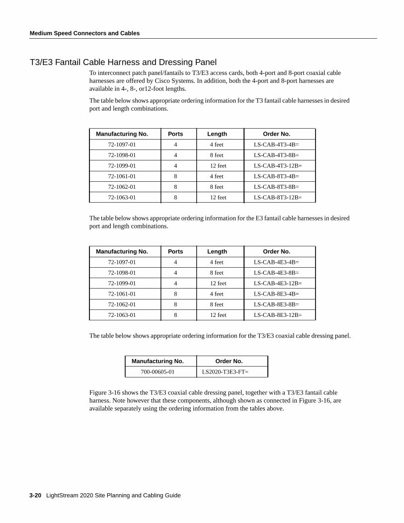
Figure 3-16 shows the T3/E3 coaxial cable dressing panel, together with a T3/E3 fantail cableharness. Note however that these components, although shown as connected in Figure 3-16, areavailable separately using the ordering information from the tables above.
Manufacturing No. Ports Length Order No.
72-1097-01 4 4 feet LS-CAB-4T3-4B=
72-1098-01 4 8 feet LS-CAB-4T3-8B=
72-1099-01 4 12 feet LS-CAB-4T3-12B=
72-1061-01 8 4 feet LS-CAB-8T3-4B=
72-1062-01 8 8 feet LS-CAB-8T3-8B=
72-1063-01 8 12 feet LS-CAB-8T3-12B=
Manufacturing No. Ports Length Order No.
72-1097-01 4 4 feet LS-CAB-4E3-4B=
72-1098-01 4 8 feet LS-CAB-4E3-8B=
72-1099-01 4 12 feet LS-CAB-4E3-12B=
72-1061-01 8 4 feet LS-CAB-8E3-4B=
72-1062-01 8 8 feet LS-CAB-8E3-8B=
72-1063-01 8 12 feet LS-CAB-8E3-12B=
Manufacturing No. Order No.
700-00605-01 LS2020-T3E3-FT=
3-20 LightStream 2020 Site Planning and Cabling Guide
Medium Speed Connectors and Cables
Figure 3-16 T3/E3 Fantail Cable Harness and Dressing Panel
T3/E3 75-Ohm Coaxial CableWhere used:
• To connect two LS2020 switches via their T3/E3 access cards.
• To connect an LS2020 T3/E3 access card to an external device.
• To connect two LS2020 switches via their T3, E3/PLCP, or E3/G.804 medium-speed accesscards.
• To connect an LS2020 T3, E3/PLCP, or E3/G.804 medium-speed access card to an externaldevice.
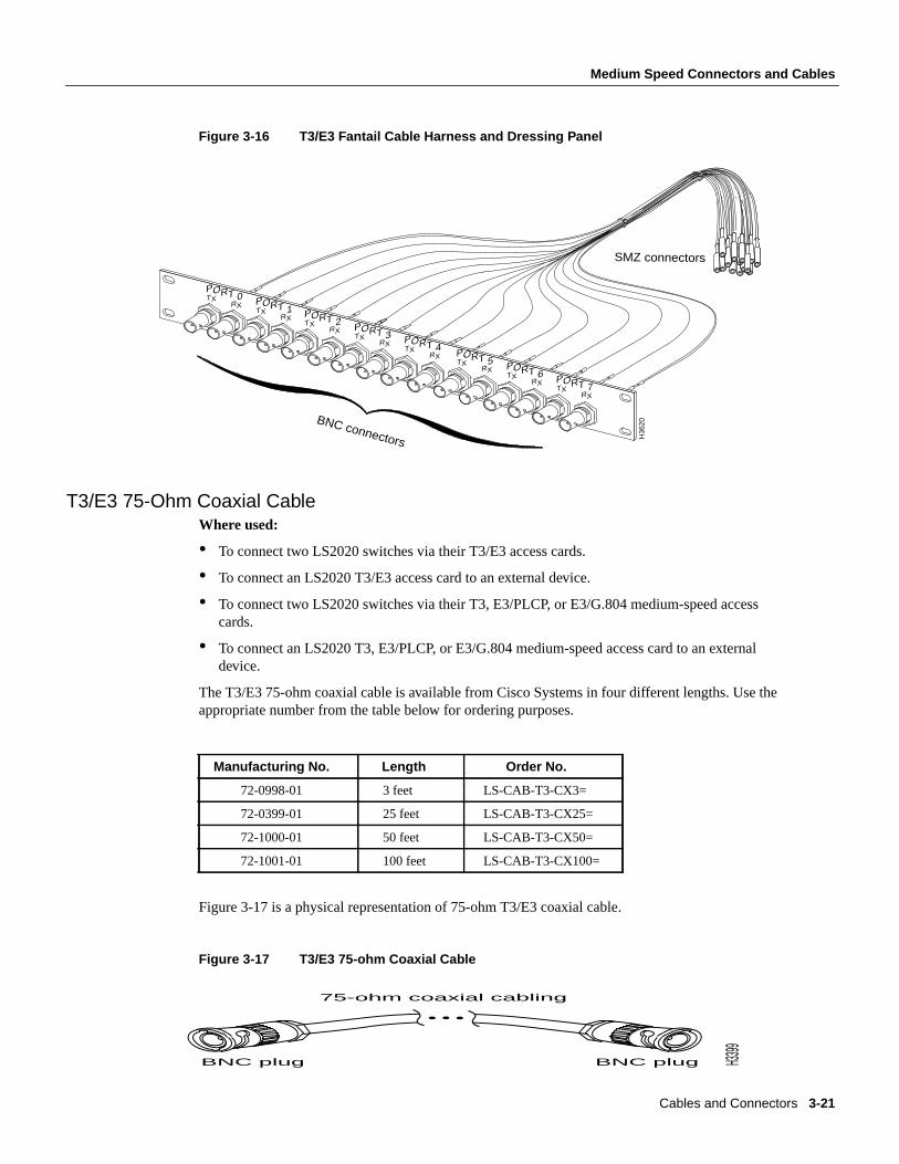
The T3/E3 75-ohm coaxial cable is available from Cisco Systems in four different lengths. Use theappropriate number from the table below for ordering purposes.
Figure 3-17 is a physical representation of 75-ohm T3/E3 coaxial cable.
Figure 3-17 T3/E3 75-ohm Coaxial Cable
Manufacturing No. Length Order No.
72-0998-01 3 feet LS-CAB-T3-CX3=
72-0399-01 25 feet LS-CAB-T3-CX25=
72-1000-01 50 feet LS-CAB-T3-CX50=
72-1001-01 100 feet LS-CAB-T3-CX100=
H36
20
PORT 0TX RX PORT 1TX RX PORT 2TX RX PORT 3TX RX PORT 4TX RX PORT 5TX RXPORT 7TX RX
PORT 6TX RX
BNC connectors
SMZ connectors
75-ohm coaxial cabling
BNC plugBNC plug H3399
Cables and Connectors 3-21
OC-3C Connectors and Cables
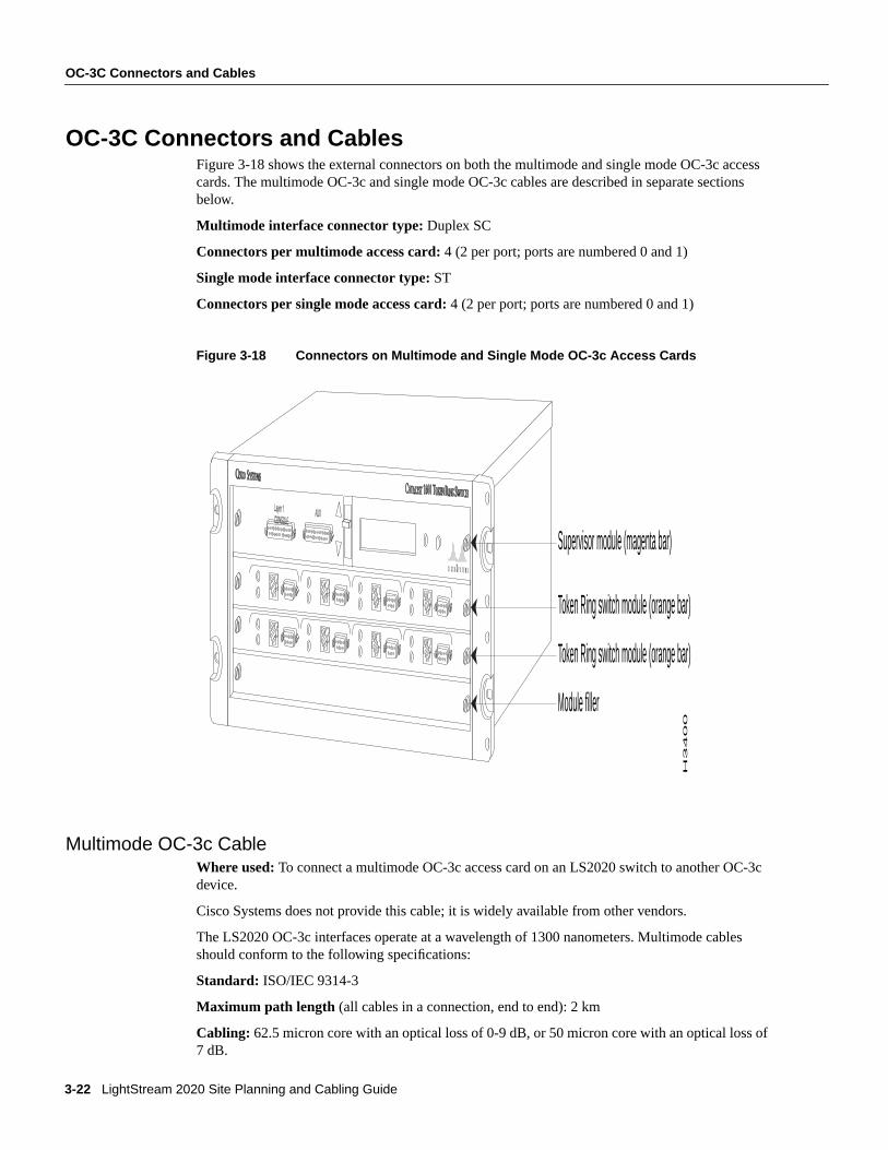
OC-3C Connectors and CablesFigure 3-18 shows the external connectors on both the multimode and single mode OC-3c accesscards. The multimode OC-3c and single mode OC-3c cables are described in separate sectionsbelow.
Multimode interface connector type: Duplex SC
Connectors per multimode access card:4 (2 per port; ports are numbered 0 and 1)
Single mode interface connector type: ST
Connectors per single mode access card:4 (2 per port; ports are numbered 0 and 1)
Figure 3-18 Connectors on Multimode and Single Mode OC-3c Access Cards
Multimode OC-3c CableWhere used: To connect a multimode OC-3c access card on an LS2020 switch to another OC-3cdevice.
Cisco Systems does not provide this cable; it is widely available from other vendors.
The LS2020 OC-3c interfaces operate at a wavelength of 1300 nanometers. Multimode cablesshould conform to the following specifications:
Standard: ISO/IEC 9314-3
Maximum path length (all cables in a connection, end to end): 2 km
Cabling: 62.5 micron core with an optical loss of 0-9 dB, or 50 micron core with an optical loss of7 dB.
H3
40
0
Supervisor module (magenta bar)
Module filler
Token Ring switch module (orange bar)
Token Ring switch module (orange bar)
3-22 LightStream 2020 Site Planning and Cabling Guide
OC-3C Connectors and Cables
Note A single fiber link should not mix 62.5 and 50 micron cable.
Note Protective covers are provided for all OC-3c access cards and cable connectors. To shieldconnectors from dust and damage, keep covers on any connectors that are not being used.
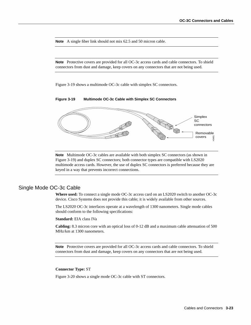
Figure 3-19 shows a multimode OC-3c cable with simplex SC connectors.
Figure 3-19 Multimode OC-3c Cable with Simplex SC Connectors
Note Multimode OC-3c cables are available with both simplex SC connectors (as shown inFigure 3-19) and duplex SC connectors; both connector types are compatible with LS2020multimode access cards. However, the use of duplex SC connectors is preferred because they arekeyed in a way that prevents incorrect connections.
Single Mode OC-3c CableWhere used:To connect a single mode OC-3c access card on an LS2020 switch to another OC-3cdevice. Cisco Systems does not provide this cable; it is widely available from other sources.
The LS2020 OC-3c interfaces operate at a wavelength of 1300 nanometers. Single mode cablesshould conform to the following specifications:
Standard: EIA class IVa
Cabling: 8.3 micron core with an optical loss of 0-12 dB and a maximum cable attenuation of 500MHz/km at 1300 nanometers.
Note Protective covers are provided for all OC-3c access cards and cable connectors. To shieldconnectors from dust and damage, keep covers on any connectors that are not being used.
Connector Type: ST
Figure 3-20 shows a single mode OC-3c cable with ST connectors.
Removablecovers
H34
01
Simplex SC connectors
Cables and Connectors 3-23
FDDI Connectors and Cables
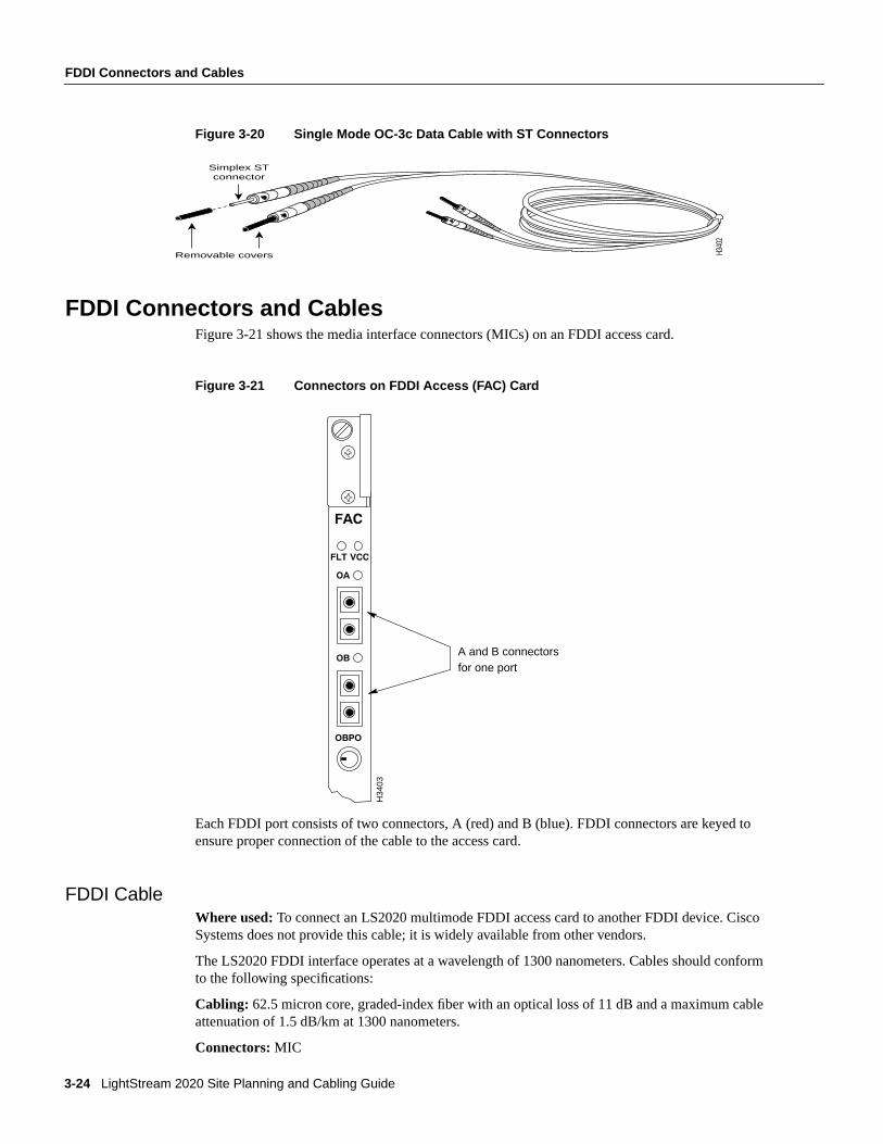
Figure 3-20 Single Mode OC-3c Data Cable with ST Connectors
FDDI Connectors and CablesFigure 3-21 shows the media interface connectors (MICs) on an FDDI access card.
Figure 3-21 Connectors on FDDI Access (FAC) Card
Each FDDI port consists of two connectors, A (red) and B (blue). FDDI connectors are keyed toensure proper connection of the cable to the access card.
FDDI CableWhere used: To connect an LS2020 multimode FDDI access card to another FDDI device. CiscoSystems does not provide this cable; it is widely available from other vendors.
The LS2020 FDDI interface operates at a wavelength of 1300 nanometers. Cables should conformto the following specifications:
Cabling: 62.5 micron core, graded-index fiber with an optical loss of 11 dB and a maximum cableattenuation of 1.5 dB/km at 1300 nanometers.
Connectors: MIC
Simplex STconnector
Removable covers H340
2
A and B connectorsfor one port
H34
03
3-24 LightStream 2020 Site Planning and Cabling Guide
Ethernet Connectors and Cables
Maximum path length: (all cables in a connection, end to end): 2 km
Note Protective covers are provided for all FDDI access card and cable connectors. To shieldconnectors from dust and damage, keep covers on any connectors that are not being used.
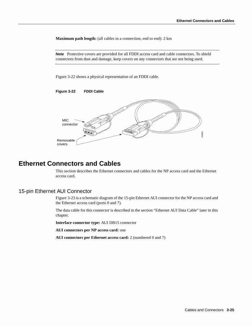
Figure 3-22 shows a physical representation of an FDDI cable.
Figure 3-22 FDDI Cable
Ethernet Connectors and CablesThis section describes the Ethernet connectors and cables for the NP access card and the Ethernetaccess card.
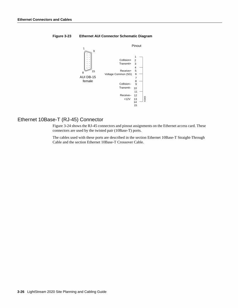
15-pin Ethernet AUI ConnectorFigure 3-23 is a schematic diagram of the 15-pin Ethernet AUI connector for the NP access card andthe Ethernet access card (ports 0 and 7).
The data cable for this connector is described in the section “Ethernet AUI Data Cable” later in thischapter.
Interface connector type:AUI DB15 connector
AUI connectors per NP access card:one
AUI connectors per Ethernet access card:2 (numbered 0 and 7)
Removablecovers
MIC connector
H34
04
Cables and Connectors 3-25
Ethernet Connectors and Cables
Figure 3-23 Ethernet AUI Connector Schematic Diagram
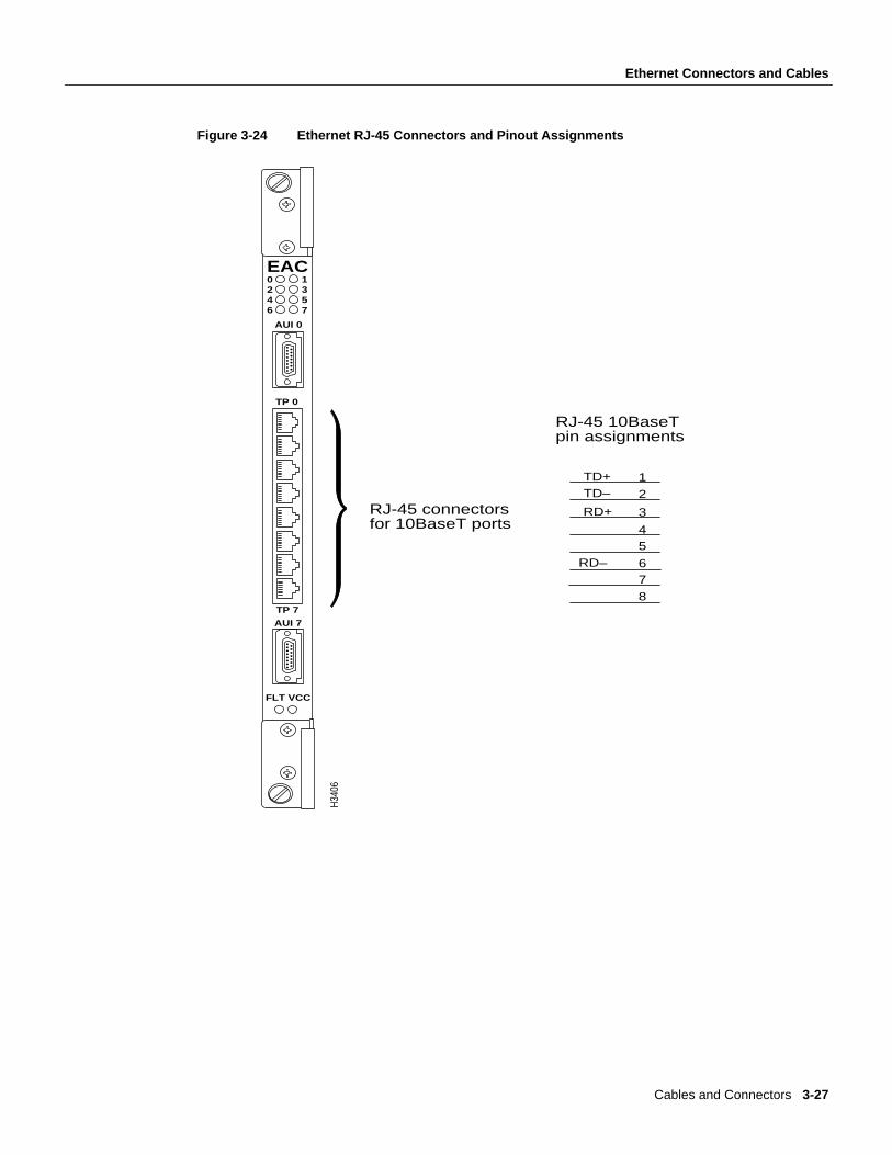
Ethernet 10Base-T (RJ-45) ConnectorFigure 3-24 shows the RJ-45 connectors and pinout assignments on the Ethernet access card. Theseconnectors are used by the twisted pair (10Base-T) ports.
The cables used with these ports are described in the section Ethernet 10Base-T Straight-ThroughCable and the section Ethernet 10Base-T Crossover Cable.
1
13+12V12Receive–
4
10Transmit–Collision–
76Voltage Common (SG)5Receive+
11
3Transmit+2Collision+
14
Pinout
H34
05
1
8
9
15
9
15
8
AUI DB-15female
3-26 LightStream 2020 Site Planning and Cabling Guide
Ethernet Connectors and Cables
Figure 3-24 Ethernet RJ-45 Connectors and Pinout Assignments
1
2
3RD+
45
6RD–7
8
TD+TD–
RJ-45 10BaseT pin assignments
RJ-45 connectors for 10BaseT ports
H34
06
EAC0246
1357
TP 0
TP 7
AUI 7
FLT VCC
AUI 0
Cables and Connectors 3-27
Ethernet Connectors and Cables
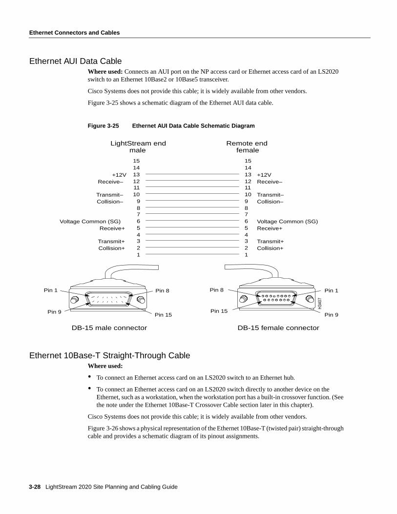
Ethernet AUI Data CableWhere used:Connects an AUI port on the NP access card or Ethernet access card of an LS2020switch to an Ethernet 10Base2 or 10Base5 transceiver.
Cisco Systems does not provide this cable; it is widely available from other vendors.
Figure 3-25 shows a schematic diagram of the Ethernet AUI data cable.
Figure 3-25 Ethernet AUI Data Cable Schematic Diagram
Ethernet 10Base-T Straight-Through CableWhere used:
• To connect an Ethernet access card on an LS2020 switch to an Ethernet hub.
• To connect an Ethernet access card on an LS2020 switch directly to another device on theEthernet, such as a workstation, when the workstation port has a built-in crossover function. (Seethe note under the Ethernet 10Base-T Crossover Cable section later in this chapter).
Cisco Systems does not provide this cable; it is widely available from other vendors.
Figure 3-26 shows a physical representation of the Ethernet 10Base-T (twisted pair) straight-throughcable and provides a schematic diagram of its pinout assignments.
Pin 1
Pin 9
Pin 8
Pin 15
Pin 1
Pin 9
Pin 8
Pin 15
male female
151413+12V12Receive–1110Transmit–
9Collision–876Voltage Common (SG)5Receive+43Transmit+2Collision+1
DB-15 male connector DB-15 female connector
+12VReceive–
Transmit–Collision–
Voltage Common (SG)Receive+
Transmit+Collision+
151413121110987654321
LightStream end Remote end
H34
07
3-28 LightStream 2020 Site Planning and Cabling Guide
Ethernet Connectors and Cables
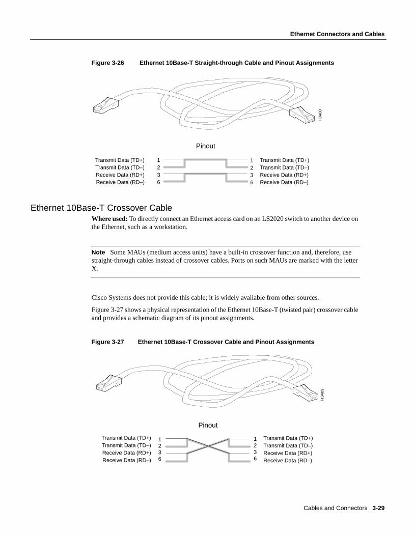
Figure 3-26 Ethernet 10Base-T Straight-through Cable and Pinout Assignments
Ethernet 10Base-T Crossover CableWhere used:To directly connect an Ethernet access card on an LS2020 switch to another device onthe Ethernet, such as a workstation.
Note Some MAUs (medium access units) have a built-in crossover function and, therefore, usestraight-through cables instead of crossover cables. Ports on such MAUs are marked with the letterX.
Cisco Systems does not provide this cable; it is widely available from other sources.
Figure 3-27 shows a physical representation of the Ethernet 10Base-T (twisted pair) crossover cableand provides a schematic diagram of its pinout assignments.
Figure 3-27 Ethernet 10Base-T Crossover Cable and Pinout Assignments
6321Transmit Data (TD+)
Receive Data (RD–)Receive Data (RD+)Transmit Data (TD–)
6321 Transmit Data (TD+)
Receive Data (RD–)Receive Data (RD+)Transmit Data (TD–)
Pinout
H34
08
Transmit Data (TD+)
Receive Data (RD–) Receive Data (RD+)Transmit Data (TD–)
Transmit Data (TD+)
Receive Data (RD–)Receive Data (RD+)Transmit Data (TD–)
Pinout
H34
09
1236
1236
Cables and Connectors 3-29
Fiber Ethernet Connectors and Cable
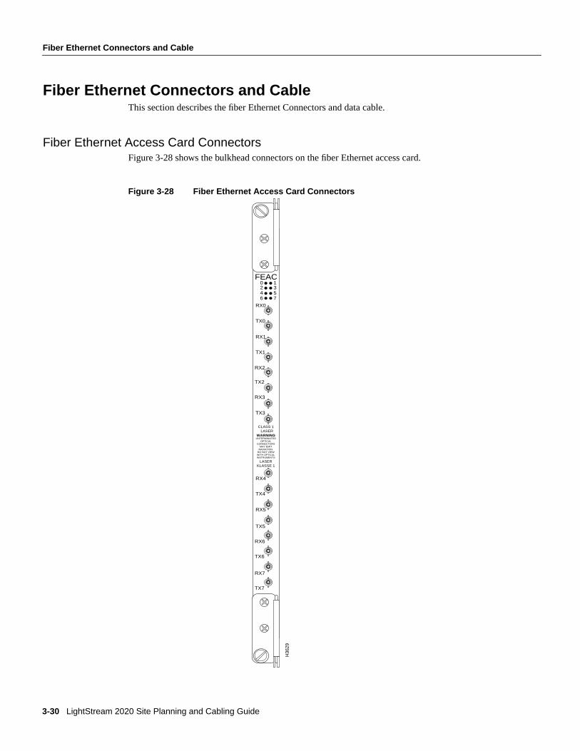
Fiber Ethernet Connectors and CableThis section describes the fiber Ethernet Connectors and data cable.
Fiber Ethernet Access Card ConnectorsFigure 3-28 shows the bulkhead connectors on the fiber Ethernet access card.
Figure 3-28 Fiber Ethernet Access Card Connectors
H36
29
RX4
TX4
RX5
TX5
RX6
TX6
RX7
TX7
RX0
FEAC
TX0
RX1
TX1
RX2
TX2
RX3
TX3
6 74 52 30 1
CLASS 1 LASER
WARNINGUNTERMINATED
OPTICALCONNECTORS
MAY EMITRADIATION.
DO NOT VIEWWITH OPTICALINSTRUMENTS
LASERKLASSE 1
3-30 LightStream 2020 Site Planning and Cabling Guide
Modem/Console Connectors and Cables
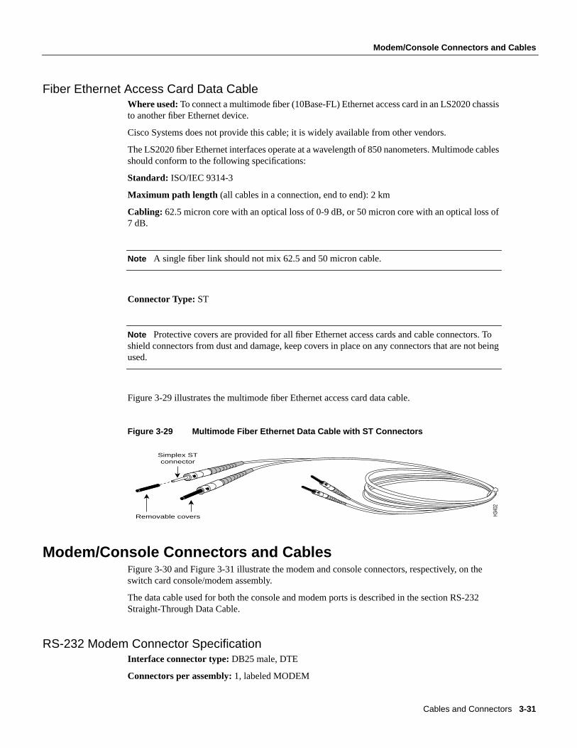
Fiber Ethernet Access Card Data CableWhere used:To connect a multimode fiber (10Base-FL) Ethernet access card in an LS2020 chassisto another fiber Ethernet device.
Cisco Systems does not provide this cable; it is widely available from other vendors.
The LS2020 fiber Ethernet interfaces operate at a wavelength of 850 nanometers. Multimode cablesshould conform to the following specifications:
Standard: ISO/IEC 9314-3
Maximum path length (all cables in a connection, end to end): 2 km
Cabling: 62.5 micron core with an optical loss of 0-9 dB, or 50 micron core with an optical loss of7 dB.
Note A single fiber link should not mix 62.5 and 50 micron cable.
Connector Type: ST
Note Protective covers are provided for all fiber Ethernet access cards and cable connectors. Toshield connectors from dust and damage, keep covers in place on any connectors that are not beingused.
Figure 3-29 illustrates the multimode fiber Ethernet access card data cable.
Figure 3-29 Multimode Fiber Ethernet Data Cable with ST Connectors
Modem/Console Connectors and CablesFigure 3-30 and Figure 3-31 illustrate the modem and console connectors, respectively, on theswitch card console/modem assembly.
The data cable used for both the console and modem ports is described in the section RS-232Straight-Through Data Cable.
RS-232 Modem Connector SpecificationInterface connector type:DB25 male, DTE
Connectors per assembly:1, labeled MODEM
Simplex STconnector
Removable covers H340
2
Cables and Connectors 3-31
Modem/Console Connectors and Cables
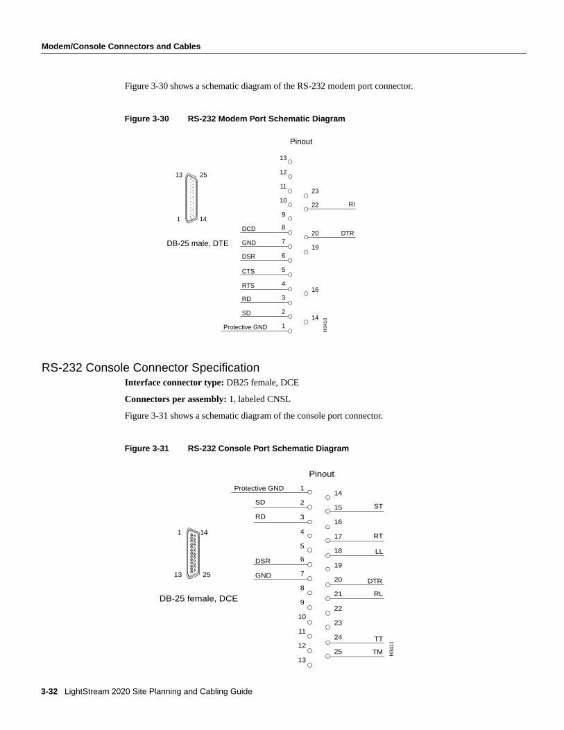
Figure 3-30 shows a schematic diagram of the RS-232 modem port connector.
Figure 3-30 RS-232 Modem Port Schematic Diagram
RS-232 Console Connector SpecificationInterface connector type:DB25 female, DCE
Connectors per assembly:1, labeled CNSL
Figure 3-31 shows a schematic diagram of the console port connector.
Figure 3-31 RS-232 Console Port Schematic Diagram
Pinout
12
11
10
9
8
7
6
5
4
3
2
1
23
22
20
19
16
14
DTR
13
GND
DSR
RD
SD
13 25
141
Protective GND
RI
DCD
CTS
RTS
H34
10
DB-25 male, DTE
1 14
2513
Pinout
2
3
4
5
6
7
8
9
10
11
12
13
14
15
16
17
18
19
20
21
22
23
24
25 TM
TT
RL
DTR
LL
RT
ST
1
GND
DSR
RD
SD
Protective GND
H34
11
DB-25 female, DCE
3-32 LightStream 2020 Site Planning and Cabling Guide
Modem/Console Connectors and Cables
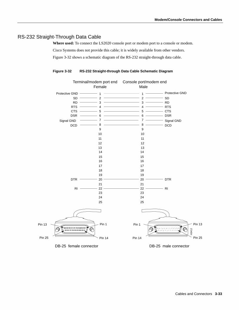
RS-232 Straight-Through Data CableWhere used:To connect the LS2020 console port or modem port to a console or modem.
Cisco Systems does not provide this cable; it is widely available from other vendors.
Figure 3-32 shows a schematic diagram of the RS-232 straight-through data cable.
Figure 3-32 RS-232 Straight-through Data Cable Schematic Diagram
12
11
10
9
8
7654321
25
24232221
20
19
18
17
1615
14
RI
DTR
13
DCD
Signal GND
DSRCTSRTS
RDSD
12
11
10
9
8
7654321
25
24232221
20
19
18
17
1615
14
RI
DTR
13
DCD
Signal GND
DSRCTSRTSRDSD
Protective GND
Female Male
Pin 13
Pin 25
Pin 1
Pin 14
Pin 1
Pin 14
Pin 13
Pin 25
DB-25 female connector DB-25 male connector
Protective GND
Terminal/modem port end Console port/modem end
H34
12
Cables and Connectors 3-33

Country Kits and Power Cordsets
Country Kits and Power Cordsets
AC-Powered LightStream 2020 SystemsA variety of power cordsets is available for AC-powered LS2020 switches. These cordsets areavailable either with systems or as spare parts. This section enables you to choose the proper cordsetfor your LS2020 site.
If you are specifying a cordset as part of a new system order, refer to the LS2020 Price List or theProducts Catalogue and order the appropriate Country Power Kit. Doing so ensures that you willalso receive the appropriate labels and instructions for the country of destination.
If you want to check the cordset included in a specific Country Power Kit, refer to Table 3-2, whichcross-references cordset product numbers and Country Power Kit models.
If you need to order a replacement cordset that is not part of a Country Power Kit, you must referencethe cordset’s part number. This part number (P/N) appears above each cordset illustrated in thefollowing section entitled “LightStream 2020 AC Power Cordsets.”
DC-powered LightStream 2020 SystemsA DC-powered system does not use a detachable power cord. The DC power cord must bepermanently wired to a DC power source. Therefore, in place of a Country Power Kit, eachDC-powered system is shipped with a DC Mounting Kit, Order Number L2020-PWR-DC=.
LightStream 2020 AC Power CordsetsEach LS2020 AC power tray is equipped with one recessed male power inlet. The power connectorsfollow IEC Standard 320 C20 and require cordsets with an IEC 320 C19 female connector. (Allcordsets offered by Cisco Systems for the LS2020 switch have IEC 320 C19 female connectors.)
Table 3-2 summarizes the specifications of AC power cordsets. The table lists the country of use,cordset rating, plug type, part number, and Country Power Kit for each cordset.
3-34 LightStream 2020 Site Planning and Cabling Guide
Country Kits and Power Cordsets
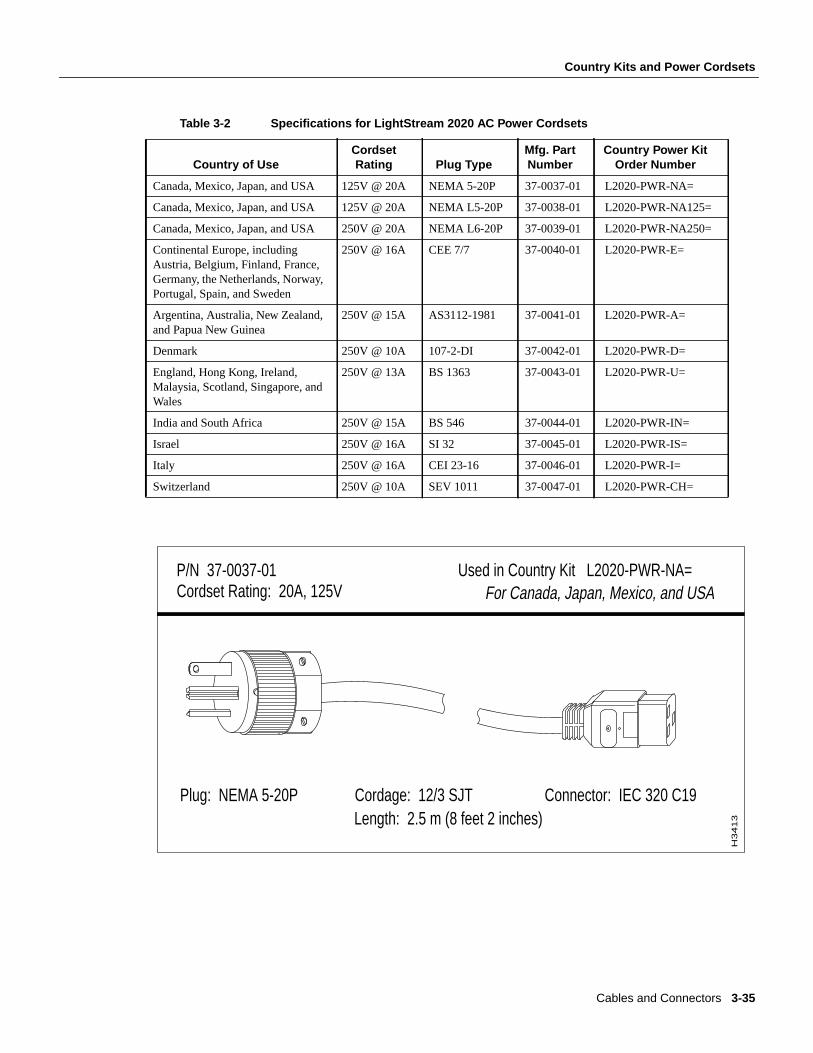
Table 3-2 Specifications for LightStream 2020 AC Power Cordsets
Country of UseCordsetRating Plug Type
Mfg. PartNumber
Country Power KitOrder Number
Canada, Mexico, Japan, and USA 125V @ 20A NEMA 5-20P 37-0037-01 L2020-PWR-NA=
Canada, Mexico, Japan, and USA 125V @ 20A NEMA L5-20P 37-0038-01 L2020-PWR-NA125=
Canada, Mexico, Japan, and USA 250V @ 20A NEMA L6-20P 37-0039-01 L2020-PWR-NA250=
Continental Europe, includingAustria, Belgium, Finland, France,Germany, the Netherlands, Norway,Portugal, Spain, and Sweden
250V @ 16A CEE 7/7 37-0040-01 L2020-PWR-E=
Argentina, Australia, New Zealand,and Papua New Guinea
250V @ 15A AS3112-1981 37-0041-01 L2020-PWR-A=
Denmark 250V @ 10A 107-2-DI 37-0042-01 L2020-PWR-D=
England, Hong Kong, Ireland,Malaysia, Scotland, Singapore, andWales
250V @ 13A BS 1363 37-0043-01 L2020-PWR-U=
India and South Africa 250V @ 15A BS 546 37-0044-01 L2020-PWR-IN=
Israel 250V @ 16A SI 32 37-0045-01 L2020-PWR-IS=
Italy 250V @ 16A CEI 23-16 37-0046-01 L2020-PWR-I=
Switzerland 250V @ 10A SEV 1011 37-0047-01 L2020-PWR-CH=
P/N 37-0037-01 Used in Country Kit L2020-PWR-NA=Cordset Rating: 20A, 125V For Canada, Japan, Mexico, and USA
Plug: NEMA 5-20P Cordage: 12/3 SJT Connector: IEC 320 C19 Length: 2.5 m (8 feet 2 inches)
H3413
Cables and Connectors 3-35
Country Kits and Power Cordsets
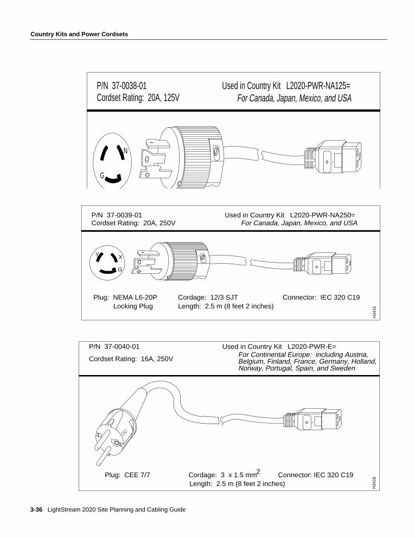
P/N 37-0038-01 Used in Country Kit L2020-PWR-NA125= Cordset Rating: 20A, 125V For Canada, Japan, Mexico, and USA
G
N
P/N 37-0039-01 Used in Country Kit L2020-PWR-NA250= Cordset Rating: 20A, 250V For Canada, Japan, Mexico, and USA
Plug: NEMA L6-20P Cordage: 12/3 SJT Connector: IEC 320 C19Locking Plug Length: 2.5 m (8 feet 2 inches)
G
Y X
H34
15
P/N 37-0040-01 Used in Country Kit L2020-PWR-E=
Cordset Rating: 16A, 250V
Plug: CEE 7/7 Cordage: 3 x 1.5 mm Connector: IEC 320 C19Length: 2.5 m (8 feet 2 inches)
H34
16
For Continental Europe: including Austria,Belgium, Finland, France, Germany, Holland,Norway, Portugal, Spain, and Sweden
2
3-36 LightStream 2020 Site Planning and Cabling Guide
Country Kits and Power Cordsets
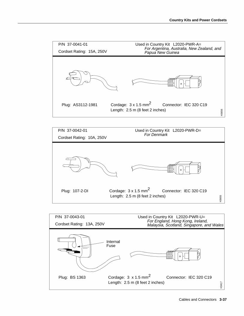
P/N 37-0041-01 Used in Country Kit L2020-PWR-A=
Cordset Rating: 15A, 250V
Plug: AS3112-1981 Cordage: 3 x 1.5 mm Connector: IEC 320 C19Length: 2.5 m (8 feet 2 inches)
H36
56
For Argentina, Australia, New Zealand, and Papua New Guinea
2
P/N 37-0042-01 Used in Country Kit L2020-PWR-D=
Cordset Rating: 10A, 250V
Plug: 107-2-DI Cordage: 3 x 1.5 mm Connector: IEC 320 C19Length: 2.5 m (8 feet 2 inches)
H36
55
For Denmark
2
P/N 37-0043-01 Used in Country Kit L2020-PWR-U=
Cordset Rating: 13A, 250V
Plug: BS 1363 Cordage: 3 x 1.5 mm Connector: IEC 320 C19Length: 2.5 m (8 feet 2 inches)
Internal Fuse
H34
17 For England, Hong Kong, Ireland, Malaysia, Scotland, Singapore, and Wales
2
Cables and Connectors 3-37
Country Kits and Power Cordsets
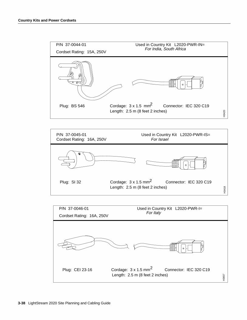
P/N 37-0044-01 Used in Country Kit L2020-PWR-IN=
Cordset Rating: 15A, 250V
Plug: BS 546 Cordage: 3 x 1.5 mm Connector: IEC 320 C19Length: 2.5 m (8 feet 2 inches)
H34
20
For India, South Africa
2
P/N 37-0045-01 Used in Country Kit L2020-PWR-IS=Cordset Rating: 16A, 250V For Israel
Plug: SI 32 Cordage: 3 x 1.5 mm Connector: IEC 320 C19Length: 2.5 m (8 feet 2 inches)
H34
18
2
P/N 37-0046-01 Used in Country Kit L2020-PWR-I=
Cordset Rating: 16A, 250V
Plug: CEI 23-16 Cordage: 3 x 1.5 mm Connector: IEC 320 C19Length: 2.5 m (8 feet 2 inches)
H36
57
For Italy
2
3-38 LightStream 2020 Site Planning and Cabling Guide
Country Kits and Power Cordsets
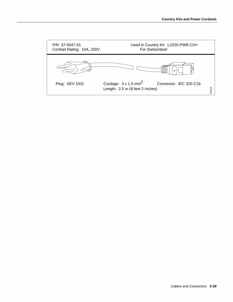
P/N 37-0047-01 Used in Country Kit L2020-PWR-CH=Cordset Rating: 10A, 250V For Switzerland
Plug: SEV 1011 Cordage: 3 x 1.5 mm Connector: IEC 320 C19Length: 2.5 m (8 feet 2 inches)
H34
19
2
Cables and Connectors 3-39

Country Kits and Power Cordsets
3-40 LightStream 2020 Site Planning and Cabling Guide