Embed Size (px)
Citation preview

CABLE TRAY MANAGEMENT SYSTEM


Cable Management SystemCable Tray
is protected by intellectual and industrial property rights . right to alterations reserved
Certificates

Cable Management SystemCable Tray
Mc - Ser
is protected by intellectual and industrial property rights . right to alterations reserved
Certificates

Cable Management SystemCable Tray
is protected by intellectual and industrial property rights . right to alterations reserved
MC -SERIES
Arabian International Co. for Steel Structures and Sheet Metal Works (AIC Steel) is leading
designer, fabricator and erector of structural steel, sheet metal and towers. We are AIC Sheet
Metal Works committed to deliver a wide range of sheet metal work solutions across the
world. Incorporated in 2016, AIC sheet metal Works has been serving the needs of HVAC
Systems, Cable Management systems, and Sheet Metal Fabrication services. Our industrial
facilities are spread across Saudi Arabia, UAE, Egypt, serving the needs of the MENA region.
We are qualifi ed professionals who are fully dedicated to serve our clients.
AIC Sheet Metal Works assure high quality standard and committed to maintain an effective
Quality Assurance System complying with International Standard ISO9001-2015 (Quality
Systems), that will sustain the company's reputation and achieve customer satisfaction. The
certifi cates that AIC holds, is a proof of how serious we are emerging to reach an international
standard that we are proud of and keep us on top of the industry in the region.
AIC Sheet Metal Works product designs are always based on the relevant international
standards and codes to produce cost effective solutions based on accurate calculations
validated by advanced testing measures in our labs to ensure products reliability followed by
continuous development to fulfi ll our customer satisfaction.
Cable Management systems offered are conforming to NEMA VE1-2017, NEMA
VE2-2013, BEAMA, IEC 61537:2007 and NFPA 70-2017 (NEC).

Cable Management SystemCable Tray
3
2
1
Mc - Ser
is protected by intellectual and industrial property rights . right to alterations reserved
4
5
MC -SERIES
Cable Tray
Cable trays have the advantage of giving you continuous support for your cables along their entire lengths. They are precisely
formed and engineered to maximize the strength capabilities of their steel. Often, they are fabricated from pregalvanized steel, for a
long corrosion resistant life, with a clean looking, high quality surface which is great for inside installation where they could be seen.
Alternatively, most trays can be hot dip galvanized after fabrication to provide a long, corrosion resistant service life even when
used outside. Depending on the design of the tray, you either use pre-made fittings to change your cable direction or
level, or fabricate these from the product itself onsite.
Cable Tray is used outdoor and indoor, have ventilation openings for air circulation and prevent accumulation of dust without
cables sagging .
is protected by intellectual and industrial property rights . right to alterations reserved
MC -SERIES

Cable Management SystemCable Tray
3
2
1
is protected by intellectual and industrial property rights . right to alterations reserved
4
5
MC -SERIES
Product Page Product Page
Straight Cable Tray 8-9
Curved Inside Riser 16
Straight Cable Tray (Roll Formed) 10-11 Cornered
Inside
Riser17
Cornered Bend (Type A) 12
Curved Outside Riser 18
Cornered Bend (Type B)
13Cornered Outside Riser 19
14Cornered Horizontal Tee (Type A)
20
Cornered Outside
Curved Bend 15
Cornered Bend (Type C)
21Cornered Horizontal Tee (Type B)

Cable Management SystemCable Tray
3
2
1
Mc - Ser
is protected by intellectual and industrial property rights . right to alterations reserved
4
5
MC -SERIES
Product Page Product Page
Cornered Horizontal Tee (Type C)
22Central Cornered Reducer (Type A)
28
Curved Horizontal Tee 23
Central Cornered Reducer (Type B)
29
Cornered Cross (Type A)
24
Side Cornered Reducer (Type A)
30
Cornered Cross (Type B) 25
Side Cornered Reducer (Type B)
31
Curved Cross
26 32
27
Cornered Cross (Type C)
Central Cornered Reducer (Type C)
33Side Cornered Reducer (Type C)

Cable Management SystemCable Tray
8
3
2
1
is protected by intellectual and industrial property rights . right to alterations reserved
4
5
MC -SERIES
MC01-Straight Cable Tray (Cut)
Ordering Code
MC01 is supplied with various material Galvanized steel G90 and G115 in accordance with ASTM A653, Black Steel in accordance with ASTM A366 with electrostatic powder coating primer paint, Hot Dipped Galvanized steel (in accordance with ASTM A385, applied after fabrication, with local coat thickness 45 microns), Stainless steel 304 and 316 in accordance with ASTM A240 and Aluminum Alloy 3003-H14 in accordance with ASTM B209.
*Other materials, coatings or fi nish type are available upon request.
MC01 is offered with different thicknesses - from Ga. 20 (1.0 mm) to Ga. 13 (2.5 mm).
Please refer to page 9.
MC01 is offered with different pattern options Solid, Wide, Narrow, Straight 100 and Staggered 100. For more detail please refer to page 9.
Different fi nish is offered, Electrostatic powder coating, or Primer paint.Different packaging option is available upon request.
MC01 is offered with various sizes.Length starting from 200 up to 3000 mm.Width starting from 100 up to 900 mm.Flange Height starting from 25 up to 150 mm.
*Other sizes are available upon request.
Material:
Thickness:
Flange Option:
Pattern Option:
Finish:
Size:
Ordering Code
Description
• Fabricated from sheet metal with high quality to protect cables.• Provide various sizes.• Various thicknesses for different load requirements.• Different Pattern and fl ange types are available.
Construction
Loading:For loading classifications and tables Please refer to Pages no. 85 to 93.

Cable Management SystemCable Tray
9
3
2
1
Mc - Ser
is protected by intellectual and industrial property rights . right to alterations reserved
4
5
MC -SERIES
MC01-Flange Option
MC01-Tray Pattern

Cable Management SystemCable Tray
10
3
2
1
is protected by intellectual and industrial property rights . right to alterations reserved
4
5
MC -SERIES
MC02-Straight Cable Tray (Roll Formed)
Ordering Code
• Fabricated from sheet metal with high quality to protect cables.• Provide various sizes.• Various thicknesses for different load requirements.• Different Pattern and fl ange types are available.
MC02 is supplied with various material Galvanized steel G90 and G115 in accordance with ASTM A653, Black Steel in accordance with ASTM A366 with electrostatic powder coating primer paint, Hot Rolled Steel in accordance with ASTM A36 with electrostatic powder coating primer paint, Hot Dipped Galvanized steel (in accordance with ASTM A385, applied after fabrication, with local coat thickness 45 microns), Stainless steel 304 and 316 in accordance with ASTM A240 and Aluminum Alloy 3003-H14 in accordance with ASTM B209.
*Other materials, coatings or fi nish type are available upon request.
MC02 is offered with different thicknesses -from Ga. 20 (1.0 mm) to Ga. 13 (2.5 mm).
Please refer to page 11.
MC02 is offered with different pattern options, Solid, Straight 50, Straight 100, Staggered 50 and Staggered 100. For more detail please refer to page 11.
Different fi nish is offered, Electrostatic powder coating,or Primer paint.Different packaging option is available upon request.
MC02 is offered with various sizes.Length starting from 2000 up to 6000 mm. Width starting from 100 up to 900 mm. Flange Height starting from 25 up to 150 mm.
*Other sizes are available upon request.
Description
Material:
Thickness:
Flange Option:
Pattern Option:
Finish:
Size:
Ordering Code
Construction
Loading:For loading classifications and tables Please refer to Pages no. 85 to 93.

Cable Management SystemCable Tray
11
3
2
1
Mc - Ser
is protected by intellectual and industrial property rights . right to alterations reserved
4
5
MC -SERIES
MC02-Flange Option
MC02-Tray Pattern

Cable Management SystemCable Tray
12
3
2
1
Mc - Ser
is protected by intellectual and industrial property rights . right to alterations reserved
4
5
MC -SERIES
MC11- Cornered Bend (Type A)
Ordering Code
Description
• Type of fi tting that changes direction of cables to meet building design.
• Fittings are provided with covers upon request.
MC11 is supplied with various material Galvanized steel G90 and G115 in accordance with ASTM A653, Black Steel in accordance with ASTM A366 with electrostatic powder coating primer paint, Hot Dipped Galvanized steel (in accordance with ASTM A385, applied after fabrication, with local coat thickness 45 microns), Stainless steel 304 and 316 in accordance with ASTM A240 and Aluminum Alloy 3003-H14 in accordance with ASTM B209.
MC11 is offered with different thicknesses -from Ga. 20 (1.0 mm) to Ga. 13 (2.5 mm).
Please refer to page 9.
MC11 is offered with several pattern options Solid, Wide and Staggered. Please refer to page 9.
Different fi nish is offered, Electrostatic powder coating, or Primer paint.Different packaging option is available upon request.
MC11 is offered with various sizes. Radius starting from 300 up to 900 mm. Angle starting from 30° up to 90°. Height starting from 25 up to 150 mm. Width starting from 100 up to 900 mm. Extension minimum value is 100 mm.
*Other sizes are available upon request.
Construction
Material:
Thickness:
Flange Option:
Pattern Option:
Finish:
Size:
Ordering Code
Material:

Cable Management SystemCable Tray
13
3
2
1
Mc - Ser
is protected by intellectual and industrial property rights . right to alterations reserved
4
5
MC -SERIES
MC12- Cornered Bend (Type B)
Ordering Code
Description
• Type of fitting that changes direction of cables to meet building design.
• Fittings are provided with covers upon request.
MC12 is supplied with various material Galvanized steel G90 and G115 in accordance with ASTM A653, Black Steel in accordance with ASTM A366 with electrostatic powder coating primer paint, Hot Dipped Galvanized steel (in accordance with ASTM A385, applied after fabrication, with local coat thickness 45 microns), Stainless steel 304 and 316 in accordance with ASTM A240 and Aluminum Alloy 3003-H14 in accordance with ASTM B209.
*Other materials, coatings or fi nish type are available upon request.
MC12 is offered with different thicknesses -from Ga. 20 (1.0 mm) to Ga. 13 (2.5 mm).
Please refer to page 9.
Pattern Option:MC12 is offered with several pattern options Solid, Wide and Staggered. Please refer to page 9.
Different fi nish is offered, Electrostatic powder coating, or Primer paint.Different packaging option is available upon request.
MC12 is offered with various sizes. Radius starting from 300 up to 900 mm. Angle starting from 30° up to 90°. Height starting from 25 up to 150 mm. Width starting from 100 up to 900 mm. Extension minimum value is 100 mm.
*Other sizes are available upon request.
Construction
Material:
Thickness:
Flange Option:
Finish:
Size:
Ordering Code

Cable Management SystemCable Tray
14
3
2
1
is protected by intellectual and industrial property rights . right to alterations reserved
4
5
MC -SERIES
MC13- Cornered Bend (Type C) Description
• Type of fitting that changes direction of cables to meet building design.
• Fittings are provided with covers upon request.
MC13 is supplied with various material Galvanized steel G90 and G115 in accordance with ASTM A653, Black Steel in accordance with ASTM A366 with electrostatic powder coating primer paint, Hot Dipped Galvanized steel (in accordance with ASTM A385, applied after fabrication, with local coat thickness 45 microns), Stainless steel 304 and 316 in accordance with ASTM A240 and Aluminum Alloy 3003-H14 in accordance with ASTM B209.
*Other materials, coatings or fi nish type are available upon request.
MC13 is offered with different thicknesses -from Ga. 20 (1.0 mm) to Ga. 13 (2.5 mm).
Please refer to page 9.
Pattern Option:MC13 is offered with several pattern options Solid, Wide and Staggered. Please refer to page 9.
Different fi nish is offered, Electrostatic powder coating, or Primer paint.Different packaging option is available upon request.
MC13 is offered with various sizes. Radius starting from 300 up to 900 mm. Angle starting from 30° up to 90°. Height starting from 25 up to 150 mm. Width starting from 100 up to 900 mm. Extension minimum value is 100 mm.
*Other sizes are available upon request.
Construction
Material:
Thickness:
Flange Option:
Finish:
Size:
OrOrderdering Codeing Code

Cable Management SystemCable Tray
15
3
2
1
Mc - Ser
is protected by intellectual and industrial property rights . right to alterations reserved
4
5
MC -SERIES
MC14- Curved Bend Description
•
• Fittings are provided with covers upon request.
MC14 is supplied with various material Galvanized steel G90 and G115 in accordance with ASTM A653, Black Steel in accordance with ASTM A366 with electrostatic powder coating primer paint, Hot Dipped Galvanized steel (in accordance with ASTM A385, applied after fabrication, with local coat thickness 45 microns), Stainless steel 304 and 316 in accordance with ASTM A240 and Aluminum Alloy 3003-H14 in accordance with ASTM B209.*Other materials, coatings or fi nish type are available upon request.
MC14 is offered with different thicknesses -from Ga. 20 (1.0 mm) to Ga. 13 (2.5 mm).
MC14 is offered with several pattern options Solid, Wide and Staggered. Please refer to page 9.
MC14 is offered with various sizes. Radius starting from 300 up to 900 mm. Angle starting from 30° up to 90°. Height starting from 25 up to 150 mm. Width starting from 100 up to 900 mm. Extension minimum value is 100 mm.
*Other sizes are available upon request.
Construction
Material:
Thickness:
Pattern Option:
Finish:
Size:
OrOrderdering Codeing CodeDifferent fi nish is offered, Electrostatic powder coating, or Primer paint.Different packaging option is available upon request.
Offers a wide range of angles to change cables directionaccording to user requirements.

Cable Management SystemCable Tray
16
3
2
1
is protected by intellectual and industrial property rights . right to alterations reserved
4
5
MC -SERIES
Construction
MC21- Curved Inside Riser
Ordering Code
•
• Fittings are provided with covers upon request.
Changes cable direction very smoothly from horizontal directionto vertical direction.
MC21 is supplied with various material Galvanized steel G90 and G115 in accordance with ASTM A653, Black Steel in accordance with ASTM A366 with electrostatic powder coating primer paint, Hot Dipped Galvanized steel (in accordance with ASTM A385, applied after fabrication, with local coat thickness 45 microns), Stainless steel 304 and 316 in accordance with ASTM A240 and Aluminum Alloy 3003-H14 in accordance with ASTM B209.
*Other materials, coatings or fi nish type are available upon request.
MC21 is offered with different thicknesses -from Ga. 20 (1.0 mm) to Ga. 13 (2.5 mm).
MC21 is offered with several pattern options Solid, Wide and Staggered. Please refer to page 9.
MC21 is offered with various sizes. Radius starting from 300 up to 900 mm. Angle starting from 30° up to 90°. Height starting from 25 up to 150 mm. Width starting from 100 up to 900 mm. Extension minimum value is 100 mm.
*Other sizes are available upon request.
Description:
Material:
Thickness:
Pattern Option:
Finish:
Size:
Different fi nish is offered, Electrostatic powder coating, or Primer paint.Different packaging option is available upon request.

Cable Management SystemCable Tray
17
3
2
1
Mc - Ser
is protected by intellectual and industrial property rights . right to alterations reserved
4
5
MC -SERIES
Construction
MC22- Cornered Inside Riser
•
• Fittings are provided with covers upon request.
Description:
Changes cable direction from horizontal direction to verticaldirection.
MC22 is supplied with various material Galvanized steel G90 and G115 in accordance with ASTM A653, Black Steel in accordance with ASTM A366 with electrostatic powder coating primer paint, Hot Dipped Galvanized steel (in accordance with ASTM A385, applied after fabrication, with local coat thickness 45 microns), Stainless steel 304 and 316 in accordance with ASTM A240 and Aluminum Alloy 3003-H14 in accordance with ASTM B209.*Other materials, coatings or fi nish type are available upon request.
Thickness:MC22 is offered with different thicknesses -from Ga. 20 (1.0 mm) to Ga. 13 (2.5 mm).
Flange Option:Please refer to page 9.
Pattern Option:MC22 is offered with several pattern options Solid, Wide and Staggered. Please refer to page 9.
MC22 is offered with various sizes. Radius starting from 300 up to 900 mm. Angle starting from 30° up to 90°. Height starting from 25 up to 150 mm. Width starting from 100 up to 900 mm. Extension minimum value is 100 mm.
*Other sizes are available upon request.
Material:
Finish:
Size:
OrOrderdering Codeing Code
Different fi nish is offered, Electrostatic powder coating, or Primer paint.Different packaging option is available upon request.

Cable Management SystemCable Tray
18
3
2
1
is protected by intellectual and industrial property rights . right to alterations reserved
4
5
MC -SERIES
MC23- Curved Outside Riser Description
•
• Fittings are provided with covers upon request.
Changes cable direction very smoothly from vertical direction tohorizontal direction.
MC23 is supplied with various material Galvanized steel G90 and G115 in accordance with ASTM A653, Black Steel in accordance with ASTM A366 with electrostatic powder coating primer paint, Hot Dipped Galvanized steel (in accordance with ASTM A385, applied after fabrication, with local coat thickness 45 microns), Stainless steel 304 and 316 in accordance with ASTM A240 and Aluminum Alloy 3003-H14 in accordance with ASTM B209.*Other materials, coatings or fi nish type are available upon request.
MC23 is offered with different thicknesses -from Ga. 20 (1.0 mm) to Ga. 13 (2.5 mm).
MC23 is offered with several pattern options Solid, Wide and Staggered. Please refer to page 9.
MC23 is offered with various sizes. Radius starting from 300 up to 900 mm. Angle starting from 30° up to 90°. Height starting from 25 up to 150 mm. Width starting from 100 up to 900 mm. Extension minimum value is 100 mm.
*Other sizes are available upon request.
Construction
Material:
Thickness:
Pattern Option:
Finish:
Size:
OrOrderdering Codeing Code
Different fi nish is offered, Electrostatic powder coating, or Primer paint.Different packaging option is available upon request.

Cable Management SystemCable Tray
19
3
2
1
Mc - Ser
is protected by intellectual and industrial property rights . right to alterations reserved
4
5
MC -SERIES
MC24- Cornered Outside Riser
MC24 is supplied with various material Galvanized steel G90 and G115 in accordance with ASTM A653, Black Steel in accordance with ASTM A366 with electrostatic powder coating primer paint, Hot Dipped Galvanized steel (in accordance with ASTM A385, applied after fabrication, with local coat thickness 45 microns), Stainless steel 304 and 316 in accordance with ASTM A240 and Aluminum Alloy 3003-H14 in accordance with ASTM B209.
*Other materials, coatings or fi nish type are available upon request.
MC24 is offered with different thicknesses -from Ga. 20 (1.0 mm) to Ga. 13 (2.5 mm).
Please refer to page 9.
Pattern Option:MC24 iis offered with several pattern options Solid, Wide and Staggered. Please refer to page 9.
MC24 is offered with various sizes. Radius starting from 300 up to 900 mm. Angle starting from 30° up to 90°. Height starting from 25 up to 150 mm. Width starting from 100 up to 900 mm. Extension minimum value is 100 mm.
*Other sizes are available upon request.
Material:
Thickness:
Flange Option:
Finish:
Size:
OrOrderdering Codeing Code
Description
•
• Fittings are provided with covers upon request.
Construction
Different fi nish is offered, Electrostatic powder coating, or Primer paint.Different packaging option is available upon request.
Changes cable direction from horizontal direction to verticaldirection.

Cable Management SystemCable Tray
20
3
2
1
is protected by intellectual and industrial property rights . right to alterations reserved
4
5
MC -SERIES
DescriptionMC31- Cornered Horizontal Tee (Type A)
OrOrderdering Codeing Code
MC31 is supplied with various material Galvanized steel G90 and G115 in accordance with ASTM A653, Black Steel in accordance with ASTM A366 with electrostatic powder coating primer paint, Hot Dipped Galvanized steel (in accordance with ASTM A385, applied after fabrication, with local coat thickness 45 microns), Stainless steel 304 and 316 in accordance with ASTM A240 and Aluminum Alloy 3003-H14 in accordance with ASTM B209.
*Other materials, coatings or fi nish type are available upon request.
MC31 is offered with different thicknesses -from Ga. 20 (1.0 mm) to Ga. 13 (2.5 mm).
Please refer to page 9.
Pattern Option:MC31 is offered with several pattern options Solid, Wide and Staggered. Please refer to page 9.
MC31 is offered with various sizes. Radius starting from 300 up to 900 mm. Width 1 starting from 100 up to 900 mm. Height starting from 25 up to 150 mm. Width 2 starting from 100 up to 900 mm. Extension minimum value is 100 mm.
*Other sizes are available upon request.
Material:
Thickness:
Flange Option:
Finish:
Size:
Construction
Different fi nish is offered, Electrostatic powder coating, or Primer paint.Different packaging option is available upon request.
• Distribute cables in two directions.
• Fittings are provided with covers upon request.
Cable Management SystemCable Tray
21
3
2
1
Mc - Ser
is protected by intellectual and industrial property rights . right to alterations reserved
4
5
MC -SERIES
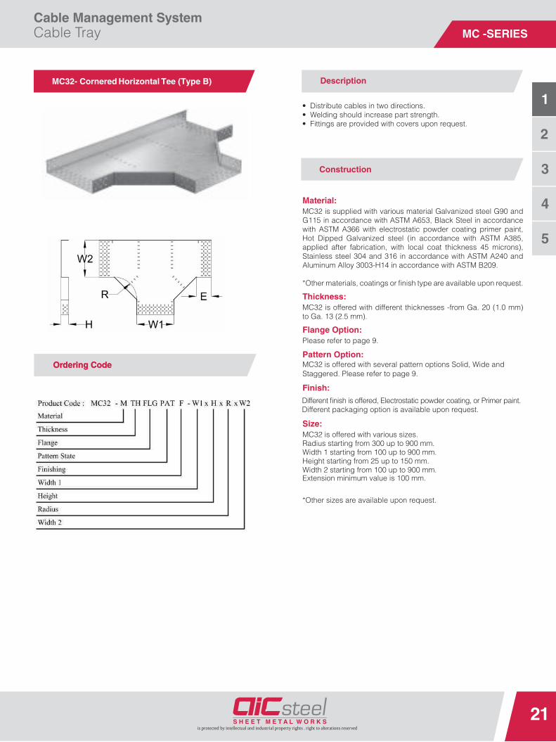
MC32- Cornered Horizontal Tee (Type B)
• Distribute cables in two directions.• Welding should increase part strength.• Fittings are provided with covers upon request.
MC32 is supplied with various material Galvanized steel G90 and G115 in accordance with ASTM A653, Black Steel in accordance with ASTM A366 with electrostatic powder coating primer paint, Hot Dipped Galvanized steel (in accordance with ASTM A385, applied after fabrication, with local coat thickness 45 microns), Stainless steel 304 and 316 in accordance with ASTM A240 and Aluminum Alloy 3003-H14 in accordance with ASTM B209.
*Other materials, coatings or fi nish type are available upon request.
MC32 is offered with different thicknesses -from Ga. 20 (1.0 mm) to Ga. 13 (2.5 mm).
Please refer to page 9.
Pattern Option:MC32 is offered with several pattern options Solid, Wide and Staggered. Please refer to page 9.
MC32 is offered with various sizes. Radius starting from 300 up to 900 mm. Width 1 starting from 100 up to 900 mm. Height starting from 25 up to 150 mm. Width 2 starting from 100 up to 900 mm. Extension minimum value is 100 mm.
*Other sizes are available upon request.
Construction
Material:
Thickness:
Flange Option:
Finish:
Size:
OrOrderdering Codeing Code
Description
Different fi nish is offered, Electrostatic powder coating, or Primer paint.Different packaging option is available upon request.

Cable Management SystemCable Tray
22
3
2
1
is protected by intellectual and industrial property rights . right to alterations reserved
4
5
MC -SERIES
MC33- Cornered Horizontal Tee (Type C)
Ordering Code
• Distribute cables in two directions.• Welding should increase part strength.• Fittings are provided with covers upon request.
MC33 is supplied with various material Galvanized steel G90 and G115 in accordance with ASTM A653, Black Steel in accordance with ASTM A366 with electrostatic powder coating primer paint, Hot Dipped Galvanized steel (in accordance with ASTM A385, applied after fabrication, with local coat thickness 45 microns), Stainless steel 304 and 316 in accordance with ASTM A240 and Aluminum Alloy 3003-H14 in accordance with ASTM B209.*Other materials, coatings or fi nish type are available upon request.
MC33 is offered with different thicknesses -from Ga. 20 (1.0 mm) to Ga. 13 (2.5 mm).
Please refer to page 9.
Pattern Option:MC33 is offered with several pattern options Solid, Wide and Staggered. Please refer to page 9.
MC33 is offered with various sizes. Radius starting from 300 up to 900 mm. Width 1 starting from 100 up to 900 mm. Height starting from 25 up to 150 mm. Width 2 starting from 100 up to 900 mm. Extension minimum value is 100 mm.
*Other sizes are available upon request.
Construction
Material:
Thickness:
Flange Option:
Finish:
Size:
Ordering Code
Description
Different fi nish is offered, Electrostatic powder coating, or Primer paint.Different packaging option is available upon request.

Cable Management SystemCable Tray
23
3
2
1
Mc - Ser
is protected by intellectual and industrial property rights . right to alterations reserved
4
5
MC -SERIES
Construction
DescriptionMC34- Curved Horizontal Tee
Ordering Code
• Distribute cables in two directions.• Fittings are provided with covers upon request.
MC34 is supplied with various material Galvanized steel G90 and G115 in accordance with ASTM A653, Black Steel in accordance with ASTM A366 with electrostatic powder coating primer paint, Hot Dipped Galvanized steel (in accordance with ASTM A385, applied after fabrication, with local coat thickness 45 microns), Stainless steel 304 and 316 in accordance with ASTM A240 and Aluminum Alloy 3003-H14 in accordance with ASTM B209.*Other materials, coatings or fi nish type are available upon request.
MC34 is offered with different thicknesses -from Ga. 20 (1.0 mm) to Ga. 13 (2.5 mm).
MC34 is offered with several pattern options Solid, Wide and Staggered. Please refer to page 9.
MC34 is offered with various sizes. Radius starting from 300 up to 900 mm. Width 1 starting from 100 up to 900 mm. Height starting from 25 up to 150 mm. Width 2 starting from 100 up to 900 mm. Extension minimum value is 100 mm.
*Other sizes are available upon request.
Material:
Thickness:
Pattern Option:
Finish:
Size:
Different fi nish is offered, Electrostatic powder coating, or Primer paint.Different packaging option is available upon request.

Cable Management SystemCable Tray
24
3
2
1
is protected by intellectual and industrial property rights . right to alterations reserved
4
5
MC -SERIES
MC41- Cornered Cross (Type A)
Ordering Code
• Making a manifold point in network.• Reduces tray width to another.• Fittings are provided with covers upon request.
MC41 is supplied with various material Galvanized steel G90 and G115 in accordance with ASTM A653, Black Steel in accordance with ASTM A366 with electrostatic powder coating primer paint, Hot Dipped Galvanized steel (in accordance with ASTM A385, applied after fabrication, with local coat thickness 45 microns), Stainless steel 304 and 316 in accordance with ASTM A240 and Aluminum Alloy 3003-H14 in accordance with ASTM B209.
*Other materials, coatings or fi nish type are available upon request.
MC41 is offered with different thicknesses -from Ga. 20 (1.0 mm) to Ga. 13 (2.5 mm).
Please refer to page 9.
Pattern Option:MC41 is offered with several pattern options Solid, Wide and Staggered. Please refer to page 9.
MC41 is offered with various sizes. Radius starting from 300 up to 900 mm. Width 1 starting from 150 up to 900 mm. Height starting from 25 up to 150 mm. Width 2 starting from 150 up to 900 mm. Extension minimum value is 100 mm.
*Other sizes are available upon request.
Construction
Material:
Thickness:
Flange Option:
Finish:
Size:
Ordering Code
Description
Different fi nish is offered, Electrostatic powder coating, or Primer paint.Different packaging option is available upon request.

Cable Management SystemCable Tray
25
3
2
1
Mc - Ser
is protected by intellectual and industrial property rights . right to alterations reserved
4
5
MC -SERIES
Construction
MC42- Cornered Cross (Type B)
Ordering Code
• Making a manifold point in network.• Reduces tray width to another.• Welding should increase part strength.• Fittings are provided with covers upon request.
MC42 is supplied with various material Galvanized steel G90 and G115 in accordance with ASTM A653, Black Steel in accordance with ASTM A366 with electrostatic powder coating primer paint, Hot Dipped Galvanized steel (in accordance with ASTM A385, applied after fabrication, with local coat thickness 45 microns), Stainless steel 304 and 316 in accordance with ASTM A240 and Aluminum Alloy 3003-H14 in accordance with ASTM B209.
*Other materials, coatings or fi nish type are available upon request.
MC42 is offered with different thicknesses -from Ga. 20 (1.0 mm) to Ga. 13 (2.5 mm).
Please refer to page 9.
MC42 is offered with several pattern options Solid, Wide and Staggered. Please refer to page 9.
MC42 is offered with various sizes. Radius starting from 300 up to 900 mm. Width 1 starting from 100 up to 900 mm. Height starting from 25 up to 150 mm. Width 2 starting from 100 up to 900 mm. Extension minimum value is 100 mm.
*Other sizes are available upon request.
Material:
Thickness:
Flange Option:
Pattern Option:
Finish:
Size:
Ordering Code
Description
Different fi nish is offered, Electrostatic powder coating, or Primer paint.Different packaging option is available upon request.

Cable Management SystemCable Tray
26
3
2
1
is protected by intellectual and industrial property rights . right to alterations reserved
4
5
MC -SERIES
Construction
MC43- Cornered Cross (Type C)
• Making a manifold point in network.• Reduces tray width to another.• Welding should increase part strength.• Fittings are provided with covers upon request.
MC43 is supplied with various material Galvanized steel G90 and G115 in accordance with ASTM A653, Black Steel in accordance with ASTM A366 with electrostatic powder coating primer paint, Hot Dipped Galvanized steel (in accordance with ASTM A385, applied after fabrication, with local coat thickness 45 microns), Stainless steel 304 and 316 in accordance with ASTM A240 and Aluminum Alloy 3003-H14 in accordance with ASTM B209.
*Other materials, coatings or fi nish type are available upon request.
MC43 is offered with different thicknesses -from Ga. 20 (1.0 mm) to Ga. 13 (2.5 mm).
Please refer to page 9.
MC43 is offered with several pattern options Solid, Wide and Staggered. Please refer to page 9.
MC43 is offered with various sizes. Radius starting from 300 up to 900 mm. Width 1 starting from 100 up to 900 mm. Height starting from 25 up to 150 mm. Width 2 starting from 100 up to 900 mm. Extension minimum value is 100 mm.
*Other sizes are available upon request.
Material:
Thickness:
Flange Option:
Pattern Option:
Size:
OrOrderdering Codeing Code
Description
Finish:Different fi nish is offered, Electrostatic powder coating, or Primer paint.Different packaging option is available upon request.

Cable Management SystemCable Tray
27
3
2
1
Mc - Ser
is protected by intellectual and industrial property rights . right to alterations reserved
4
5
MC -SERIES
MC44- Curved Cross Description
• Making a manifold point in network.• Reduces tray width to another.• Fittings are provided with covers upon request.
MC44 is supplied with various material Galvanized steel G90 and G115 in accordance with ASTM A653, Black Steel in accordance with ASTM A366 with electrostatic powder coating primer paint, Hot Dipped Galvanized steel (in accordance with ASTM A385, applied after fabrication, with local coat thickness 45 microns), Stainless steel 304 and 316 in accordance with ASTM A240 and Aluminum Alloy 3003-H14 in accordance with ASTM B209.*Other materials, coatings or fi nish type are available upon request.
MC44 is offered with different thicknesses -from Ga. 20 (1.0 mm) to Ga. 13 (2.5 mm).
MC44 is offered with several pattern options Solid, Wide and Staggered. Please refer to page 9.
MC44 is offered with various sizes. Radius starting from 300 up to 900 mm. Width 1 starting from 100 up to 900 mm. Height starting from 25 up to 150 mm. Width 2 starting from 100 up to 900 mm. Extension minimum value is 100 mm.
*Other sizes are available upon request.
Material:
Thickness:
Pattern Option:
Finish:
Size:
OrOrderdering Codeing Code
Construction
Different fi nish is offered, Electrostatic powder coating, or Primer paint.Different packaging option is available upon request.

Cable Management SystemCable Tray
28
3
2
1
is protected by intellectual and industrial property rights . right to alterations reserved
4
5
MC -SERIES
MC51- Central Cornered Reducer (Type A)
• Reduces cable tray width to another with single fitting.• Fittings are provided with covers upon request.
Description:
OrOrderdering Codeing Code
MC51 is supplied with various material Galvanized steel G90 and G115 in accordance with ASTM A653, Black Steel in accordance with ASTM A366 with electrostatic powder coating primer paint, Hot Dipped Galvanized steel (in accordance with ASTM A385, applied after fabrication, with local coat thickness 45 microns), Stainless steel 304 and 316 in accordance with ASTM A240 and Aluminum Alloy 3003-H14 in accordance with ASTM B209.
*Other materials, coatings or fi nish type are available upon request.
MC51 is offered with different thicknesses -from Ga. 20 (1.0 mm) to Ga. 13 (2.5 mm).
Please refer to page 9.
Pattern Option:MC51 is offered with several pattern options Solid, Wide and Staggered. Please refer to page 9.
MC51 is offered with various sizes. Width 1 starting from 150 up to 900 mm. Height starting from 25 up to 150 mm. Width 2 starting from 150 up to 900 mm. Extension minimum value is 100 mm. Length is 500 mm minimum.
*Other sizes are available upon request.
Material:
Thickness:
Flange Option:
Finish:
Size:
Construction
Different fi nish is offered, Electrostatic powder coating, or Primer paint.Different packaging option is available upon request.

Cable Management SystemCable Tray
29
3
2
1
Mc - Ser
is protected by intellectual and industrial property rights . right to alterations reserved
4
5
MC -SERIES
MC52- Central Cornered Reducer (Type B) Description
• Reduces cable tray width to another with single fi tting.• Welding should increase part strength.• Fittings are provided with covers upon request.
MC52 is supplied with various material Galvanized steel G90 and G115 in accordance with ASTM A653, Black Steel in accordance with ASTM A366 with electrostatic powder coating primer paint, Hot Dipped Galvanized steel (in accordance with ASTM A385, applied after fabrication, with local coat thickness 45 microns), Stainless steel 304 and 316 in accordance with ASTM A240 and Aluminum Alloy 3003-H14 in accordance with ASTM B209.
*Other materials, coatings or fi nish type are available upon request.
MC52 is offered with different thicknesses -from Ga. 20 (1.0 mm) to Ga. 13 (2.5 mm).
Pattern Option:MC52 is offered with several pattern options Solid, Wide and Staggered. Please refer to page 9.
Please refer to page 9.
MC52 is offered with various sizes. Width 1 starting from 100 up to 900 mm. Height starting from 25 up to 150 mm. Width 2 starting from 100 up to 900 mm. Extension minimum value is 100 mm.Length is 500 mm minimum.
*Other sizes are available upon request.
Material:
Thickness:
Flange Option:
Finish:
Size:
OrOrderdering Codeing Code
Construction
Different fi nish is offered, Electrostatic powder coating, or Primer paint.Different packaging option is available upon request.

Cable Management SystemCable Tray
30
3
2
1
is protected by intellectual and industrial property rights . right to alterations reserved
4
5
MC -SERIES
MC53- Central Cornered Reducer (Type C)
Ordering Code
Description
• Reduces cable tray width to another with single fi tting.• Welding should increase part strength.• Fittings are provided with covers upon request.
MC53 is supplied with various material Galvanized steel G90 and G115 in accordance with ASTM A653, Black Steel in accordance with ASTM A366 with electrostatic powder coating primer paint, Hot Dipped Galvanized steel (in accordance with ASTM A385, applied after fabrication, with local coat thickness 45 microns), Stainless steel 304 and 316 in accordance with ASTM A240 and Aluminum Alloy 3003-H14 in accordance with ASTM B209.*Other materials, coatings or fi nish type are available upon request.
MC53 is offered with different thicknesses -from Ga. 20 (1.0 mm) to Ga. 13 (2.5 mm).
Pattern Option:MC53 is offered with several pattern options Solid, Wide and Staggered. Please refer to page 9.
Please refer to page 9.
MC53 is offered with various sizes. Width 1 starting from 150 up to 900 mm. Height starting from 25 up to 150 mm. Width 2 starting from 150 up to 900 mm. Extension minimum value is 100 mm. Length is 500 mm minimum.
*Other sizes are available upon request.
Material:
Thickness:
Flange Option:
Finish:
Size:
Ordering Code
Construction
Different fi nish is offered, Electrostatic powder coating, or Primer paint.Different packaging option is available upon request.

Cable Management SystemCable Tray
31
3
2
1
Mc - Ser
is protected by intellectual and industrial property rights . right to alterations reserved
4
5
MC -SERIES
MC61- Side Cornered Reducer (Type A)
Ordering Code
Description
• Used to collect cables from large width to small width or vice versa.• Fittings are provided with covers upon request.
MC61 is supplied with various material Galvanized steel G90 and G115 in accordance with ASTM A653, Black Steel in accordance with ASTM A366 with electrostatic powder coating primer paint, Hot Dipped Galvanized steel (in accordance with ASTM A385, applied after fabrication, with local coat thickness 45 microns), Stainless steel 304 and 316 in accordance with ASTM A240 and Aluminum Alloy 3003-H14 in accordance with ASTM B209.*Other materials, coatings or fi nish type are available upon request.
Thickness:MC61 is offered with different thicknesses -from Ga. 20 (1.0 mm) to Ga. 13 (2.5 mm).
Pattern Option:MC61 is offered with several pattern options Solid, Wide and Staggered. Please refer to page 9.
Please refer to page 9.
MC61 is offered with various sizes. Width 1 starting from 100 up to 900 mm. Height starting from 25 up to 150 mm. Width 2 starting from 100 up to 900 mm. Extension minimum value is 100 mm. Length is 500 mm minimum.
*Other sizes are available upon request.
Material:
Flange Option:
Finish:
Size:
Ordering Code
Construction
Different fi nish is offered, Electrostatic powder coating, or Primer paint.Different packaging option is available upon request.
Reducer Type:MC61 is available with two types Right and Left upon your request.

Cable Management SystemCable Tray
32
3
2
1
is protected by intellectual and industrial property rights . right to alterations reserved
4
5
MC -SERIES
MC62- Side Cornered Reducer (Type B)
Ordering Code
Description
• Used to collect cables from large width to small width or vice versa.• Welding increases part strength.• Fittings are provided with covers upon request.
MC62 is supplied with various material Galvanized steel G90 and G115 in accordance with ASTM A653, Black Steel in accordance with ASTM A366 with electrostatic powder coating primer paint, Hot Dipped Galvanized steel (in accordance with ASTM A385, applied after fabrication, with local coat thickness 45 microns), Stainless steel 304 and 316 in accordance with ASTM A240 and Aluminum Alloy 3003-H14 in accordance with ASTM B209.*Other materials, coatings or fi nish type are available upon request.
MC62 is offered with different thicknesses -from Ga. 20 (1.0 mm) to Ga. 13 (2.5 mm).
Pattern Option:MC62 is offered with several pattern options Solid, Wide and Staggered. Please refer to page 9.
Please refer to page 9.
MC62 is offered with various sizes. Width 1 starting from 100 up to 900 mm. Height starting from 25 up to 150 mm. Width 2 starting from 100 up to 900 mm. Extension minimum value is 100 mm. Length is 500 mm minimum.*Other sizes are available upon request.
Material:
Thickness:
Flange Option:
Finish:
Size:
Ordering Code
Construction
Different fi nish is offered, Electrostatic powder coating, or Primer paint.Different packaging option is available upon request.
Reducer Type:MC62 is available with two types Right and Left upon your request.

Cable Management SystemCable Tray
33
3
2
1
Mc - Ser
is protected by intellectual and industrial property rights . right to alterations reserved
4
5
MC -SERIES
MC63- Side Cornered Reducer (Type C) Description
• Used to collect cables from large width to small width or vice versa.• Welding increases part strength.• Fittings are provided with covers upon request.
MC63 is supplied with various material Galvanized steel G90 and G115 in accordance with ASTM A653, Black Steel in accordance with ASTM A366 with electrostatic powder coating primer paint, Hot Dipped Galvanized steel (in accordance with ASTM A385, applied after fabrication, with local coat thickness 45 microns), Stainless steel 304 and 316 in accordance with ASTM A240 and Aluminum Alloy 3003-H14 in accordance with ASTM B209.
*Other materials, coatings or fi nish type are available upon request.
MC63 is offered with different thicknesses -from Ga. 20 (1.0 mm) to Ga. 13 (2.5 mm).
Pattern Option:MC63 is offered with several pattern options Solid, Wide and Staggered. Please refer to page 9.
Please refer to page 9.
MC63 is offered with various sizes. Width 1 starting from 100 up to 900 mm. Height starting from 25 up to 150 mm. Width 2 starting from 100 up to 900 mm. Extension minimum value is 100 mm. Length is 500 mm minimum.*Other sizes are available upon request.
Material:
Thickness:
Flange Option:
Finish:
Size:
OrOrderdering Codeing Code
Construction
Different fi nish is offered, Electrostatic powder coating, or Primer paint.Different packaging option is available upon request.
Reducer Type:MC63 is available with two types Right and Left upon your request.
Cable Management SystemCable Tray
34
3
2
1
is protected by intellectual and industrial property rights . right to alterations reserved
4
5
MC -SERIES
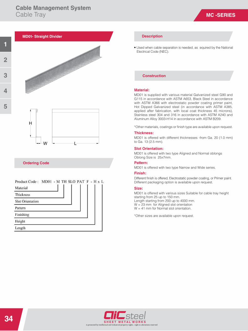
MD01- Straight Divider
Ordering Code
Description
••• Used when cable separation is needed, as equired by the NationalElectrical Code (NEC).
MD01 is supplied with various material Galvanized steel G90 and G115 in accordance with ASTM A653, Black Steel in accordance with ASTM A366 with electrostatic powder coating primer paint, Hot Dipped Galvanized steel (in accordance with ASTM A385, applied after fabrication, with local coat thickness 45 microns), Stainless steel 304 and 316 in accordance with ASTM A240 and Aluminum Alloy 3003-H14 in accordance with ASTM B209.
*Other materials, coatings or fi nish type are available upon request.
MD01 is offered with different thicknesses -from Ga. 20 (1.0 mm) to Ga. 13 (2.5 mm).
MD01 is offered with two type Narrow and Wide series.
MD01 is offered with two type Aligned and Normal oblongsOblong Size is 25x7mm.
MD01 is offered with various sizes Suitable for cable tray height starting from 25 up to 150 mm.Length starting from 200 up to 4000 mm.W = 23 mm for Aligned slot orientationW = 41 mm for Normal slot orientation.
*Other sizes are available upon request.
Material:
Thickness:
Pattern:
Slot Orientation:
Finish:
Size:
Construction
Different fi nish is offered, Electrostatic powder coating, or Primer paint.Different packaging option is available upon request.

Cable Management SystemCable Tray
35
Mc - Ser
is protected by intellectual and industrial property rights . right to alterations reserved
3
2
1
4
5
MD -SERIES

MC -SERIES
SystemCovers

31

Cable Management SystemCable Tray Covers
38
3
2
1
is protected by intellectual and industrial property rights . right to alterations reserved
4
5
MV -SERIES
MV01- Straight Cable Tray Cover
Ordering Code
Description
• covers are typically added when additional cable protection is
• It is recommended to install covers the fi rst six feet of a cable tray
• Cables should always be protected from possible falling objects.• Covers come with louvered option for more air ventilation.
required .
system extending vertically from a fl oor penetration.
MV01 is supplied with various material Galvanized steel G90 and G115 in accordance with ASTM A653, Black Steel in accordance with ASTM A366 with electrostatic powder coating primer paint, Hot Dipped Galvanized steel (in accordance with ASTM A385, applied after fabrication, with local coat thickness 45 microns), Stainless steel 304 and 316 in accordance with ASTM A240 and Aluminum Alloy 3003-H14 in accordance with ASTM B209.
*Other materials, coatings or fi nish type are available upon request.
Thickness:MV01 is offered with different thicknesses 0.8, 1.0, 1.2 and 1.5mm.
MV01 is offered with two different patterns Solid and Louvered.
MV01 is offered with various sizes.Width starting from 100 up to 900 mm.Length starting from 200 up to 4000 mm.
*Other sizes are available upon request.
Material:
Pattern Option:
Finish:
Size:
Ordering CodeOrdering CodeOrdering Code
Construruction
Different fi nish is offered, Electrostatic powder coating, or Primer paint.Different packaging option is available upon request.
Cover Flange Height is 13mm.
Cable Tray Flange option:Cover design suitable for the corresponding Cable Tray Flange option.

Cable Management SystemCable Tray Covers
39
3
2
1
is protected by intellectual and industrial property rights . right to alterations reserved
4
5
MV -SERIES
Cover- Pattern option
Schematic Drawing for Cover Assembly
1 Cable Tray Body 2 Cover
3 MA71 C-CLAMP 4 Fastner
5 Hexagon Nut 6 Washer
7 washer 8 Hexagonal screw

Cable Management SystemCable Tray Covers
40
3
2
1
is protected by intellectual and industrial property rights . right to alterations reserved
4
5
MV -SERIES
MV11 -Cornered Bend Cover (Type A)
Ordering Code
Description
MV11 is supplied with various material Galvanized steel G90 and G115 in accordance with ASTM A653, Black Steel in accordance with ASTM A366 with electrostatic powder coating primer paint, Hot Dipped Galvanized steel (in accordance with ASTM A385, applied after fabrication, with local coat thickness 45 microns), Stainless steel 304 and 316 in accordance with ASTM A240 and Aluminum Alloy 3003-H14 in accordance with ASTM B209.
*Other materials, coatings or fi nish type are available upon request.
Thickness:MV11 is offered with different thicknesses 0.8, 1.0, 1.2 and 1.5 mm.
Pattern Option:MV11 is offered with two different patterns Solid and Louvered, for More detail about louver dimensions please refer to pager no. 39.
MV11 is offered with various sizes.Radius starting from 300 up to 900 mm.Angle starting from 30° up to 90°.Width starting from 100 up to 900 mm.
Material:
Finish:
Size:
Ordering Code
Construction
Different fi nish is offered, Electrostatic powder coating, or Primer paint.Different packaging option is available upon request.
• covers are typically added when additional cable protection is
• It is recommended to install covers the fi rst six feet of a cable tray
• Cables should always be protected from possible falling objects.• Covers come with louvered option for more air ventilation.
required .
system extending vertically from a fl oor penetration.
*Other sizes are available upon request.
Cover Flange Height is 13mm.
Cable Tray Flange option:Cover design suitable for the corresponding Cable Tray Flange option.

Cable Management SystemCable Tray Covers
41
3
2
1
is protected by intellectual and industrial property rights . right to alterations reserved
4
5
MV -SERIES
MV12- Cornered Bend Cover (Type B)
Ordering Code
Description
MV12 is supplied with various material Galvanized steel G90 and G115 in accordance with ASTM A653, Black Steel in accordance with ASTM A366 with electrostatic powder coating primer paint, Hot Dipped Galvanized steel (in accordance with ASTM A385, applied after fabrication, with local coat thickness 45 microns), Stainless steel 304 and 316 in accordance with ASTM A240 and Aluminum Alloy 3003-H14 in accordance with ASTM B209.
*Other materials, coatings or fi nish type are available upon request.
Thickness:MV12 is offered with different thicknesses 0.8, 1.0, 1.2and 1.5 mm.
Pattern Option:MV12 is offered with two different patterns Solid and Louvered, for More detail about louver dimensions please refer to pager no. 39.
Material:
Finish:
Size:
Ordering Code
Construction
Different fi nish is offered, Electrostatic powder coating, or Primer paint.Different packaging option is available upon request.
• covers are typically added when additional cable protection is
• It is recommended to install covers the fi rst six feet of a cable tray
• Cables should always be protected from possible falling objects.• Covers come with louvered option for more air ventilation.
required .
system extending vertically from a fl oor penetration.
*Other sizes are available upon request.
MV12 is offered with various sizes. Radius starting from 300 up to 900 mm. Angle starting from 30° up to 90°. Width starting from 100 up to 900 mm. Extension minimum value is 100 mm.Cover Flange Height is 13mm.
Cable Tray Flange option:Cover design suitable for the corresponding Cable Tray Flange option.

Cable Management SystemCable Tray Covers
42
3
2
1
is protected by intellectual and industrial property rights . right to alterations reserved
4
5
MV -SERIES
MV13- Cornered Bend Cover (Type C) Description
MV13 is supplied with various material Galvanized steel G90 and G115 in accordance with ASTM A653, Black Steel in accordance with ASTM A366 with electrostatic powder coating primer paint, Hot Dipped Galvanized steel (in accordance with ASTM A385, applied after fabrication, with local coat thickness 45 microns), Stainless steel 304 and 316 in accordance with ASTM A240 and Aluminum Alloy 3003-H14 in accordance with ASTM B209.
*Other materials, coatings or fi nish type are available upon request.
Thickness:MV13 is offered with different thicknesses 0.8, 1.0, 1.2and 1.5 mm.
Pattern Option:MV13 is offered with two different patterns Solid and Louvered, for More detail about louver dimensions please refer to pager no. 39.
Material:
Size:
OrOrderdering Codeing Code
Construction
Finish:Different fi nish is offered, Electrostatic powder coating, or Primer paint.Different packaging option is available upon request.
••
•• It is recommended to install covers the fi rst six feet of a cable tray
•• Cables should always be p otected from possible falling objects.•• Covers come with louvered option for more air ventilation.
covers a e typically added when additional cable protection isrequired .
system extending vertically from a fl oor penetration.
*Other sizes are available upon request.
MV13 is offered with various sizes. Radius starting from 300 up to 900 mm. Angle starting from 30° up to 90°. Width starting from 100 up to 900 mm. Extension minimum value is 100 mm. Cover Flange Height is 13mm.
Cable Tray Flange option:Cover design suitable for the corresponding Cable Tray Flange option.

Cable Management SystemCable Tray Covers
43
3
2
1
is protected by intellectual and industrial property rights . right to alterations reserved
4
5
MV -SERIES
MV14- Curved Bend Cover Description
MV14 is supplied with various material Galvanized steel G90 and G115 in accordance with ASTM A653, Black Steel in accordance with ASTM A366 with electrostatic powder coating primer paint, Hot Dipped Galvanized steel (in accordance with ASTM A385, applied after fabrication, with local coat thickness 45 microns), Stainless steel 304 and 316 in accordance with ASTM A240 and Aluminum Alloy 3003-H14 in accordance with ASTM B209.
*Other materials, coatings or fi nish type are available upon request.
Thickness:MV14 is offered with different thicknesses 0.8, 1.0, 1.2 and 1.5 mm.
MV14 is offered with two different patterns Solid and Louvered.For More detail about louver dimensions please refer to pager no. 39.
Material:
Pattern Option:
Size:
OrOrderdering Codeing Code
Construction
Finish:Different fi nish is offered, Electrostatic powder coating, or Primer paint.Different packaging option is available upon request.
••
•• It is recommended to install covers the fi rst six feet of a cable tray
•• Cables should always be p otected from possible falling objects.•• Covers come with louvered option for more air ventilation.
covers a e typically added when additional cable protection isrequired .
system extending vertically from a fl oor penetration.
*Other sizes are available upon request.
MV14 is offered with various sizes. Radius starting from 300 up to 900 mm. Angle starting from 30° up to 90°. Width starting from 100 up to 900 mm. Extension minimum value is 100 mm. Cover Flange Height is 10mm.
Cable Management SystemCable Tray Covers
44
3
2
1
is protected by intellectual and industrial property rights . right to alterations reserved
4
5
MV -SERIES
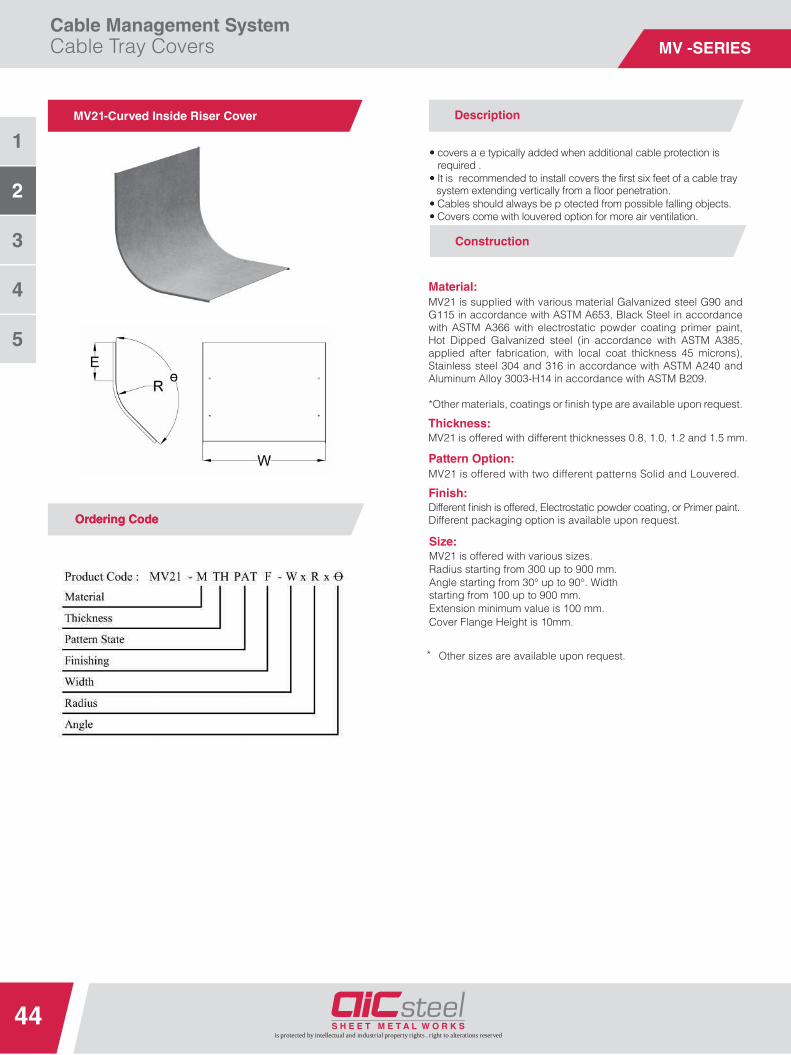
MV21-Curved Inside Riser Cover Description
MV21 is supplied with various material Galvanized steel G90 and G115 in accordance with ASTM A653, Black Steel in accordance with ASTM A366 with electrostatic powder coating primer paint, Hot Dipped Galvanized steel (in accordance with ASTM A385, applied after fabrication, with local coat thickness 45 microns), Stainless steel 304 and 316 in accordance with ASTM A240 and Aluminum Alloy 3003-H14 in accordance with ASTM B209.
*Other materials, coatings or fi nish type are available upon request.
Thickness:MV21 is offered with different thicknesses 0.8, 1.0, 1.2 and 1.5 mm.
Pattern Option:MV21 is offered with two different patterns Solid and Louvered.
Material:
OrOrderdering Codeing Code
Construction
Finish:Different fi nish is offered, Electrostatic powder coating, or Primer paint.Different packaging option is available upon request.
••
•• It is recommended to install covers the fi rst six feet of a cable tray
•• Cables should always be p otected from possible falling objects.•• Covers come with louvered option for more air ventilation.
covers a e typically added when additional cable protection isrequired .
system extending vertically from a fl oor penetration.
* Other sizes are available upon request.
Size:MV21 is offered with various sizes. Radius starting from 300 up to 900 mm. Angle starting from 30° up to 90°. Width starting from 100 up to 900 mm. Extension minimum value is 100 mm.Cover Flange Height is 10mm.

Cable Management SystemCable Tray Covers
45
3
2
1
is protected by intellectual and industrial property rights . right to alterations reserved
4
5
MV -SERIES
MV22- Cornered Inside Rise Cover Description
MV22 is supplied with various material Galvanized steel G90 and G115 in accordance with ASTM A653, Black Steel in accordance with ASTM A366 with electrostatic powder coating primer paint, Hot Dipped Galvanized steel (in accordance with ASTM A385, applied after fabrication, with local coat thickness 45 microns), Stainless steel 304 and 316 in accordance with ASTM A240 and Aluminum Alloy 3003-H14 in accordance with ASTM B209.
*Other materials, coatings or fi nish type are available upon request.
Thickness:MV22 is offered with different thicknesses 0.8, 1.0, 1.2 and 1.5 mm.
Pattern Option:MV22 is offered with two different patterns Solid and Louvered.
MV22 is offered with various sizes.Radius starting from 300 up to 900 mm.Angle starting from 30° up to 90°. Widthstarting from 100 up to 900 mm.Extension minimum value is 100 mm.Cover Flange Height is 13mm.
Material:
Size:
OrOrderdering Codeing Code
Construction
Finish:Different fi nish is offered, Electrostatic powder coating, or Primer paint.Different packaging option is available upon request.
•
•• It is recommended to install covers the fi rst six feet of a cable tray
•• Cables should always be p otected from possible falling objects.•• Covers come with louvered option for more air ventilation.
covers are typically added when additional cable protection isrequired .
system extending vertically from a fl oor penetration.
*Other sizes are available upon request.
Cable Tray Flange option:Cover design suitable for the corresponding Cable TrayFlange option.

Cable Management SystemCable Tray Covers
46
3
2
1
is protected by intellectual and industrial property rights . right to alterations reserved
4
5
MV -SERIES
MV23- Curved Outside Riser Cover Description
MV23 is supplied with various material Galvanized steel G90 and G115 in accordance with ASTM A653, Black Steel in accordance with ASTM A366 with electrostatic powder coating primer paint, Hot Dipped Galvanized steel (in accordance with ASTM A385, applied after fabrication, with local coat thickness 45 microns), Stainless steel 304 and 316 in accordance with ASTM A240 and Aluminum Alloy 3003-H14 in accordance with ASTM B209.
*Other materials, coatings or fi nish type are available upon request.
Thickness:MV23 is offered with different thicknesses 0.8, 1.0, 1.2 and 1.5 mm.
Pattern Option:MV23 is offered with two different patterns Solid and Louvered.
Material:
Size:
OrOrderdering Codeing Code
Construction
Finish:Different fi nish is offered, Electrostatic powder coating, or Primer paint.Different packaging option is available upon request.
•
• It is recommended to install covers the fi rst six feet of a cable tray
• Cables should always be protected from possible falling objects.• Covers come with louvered option for more air ventilation.
covers are typically added when additional cable protection isrequired .
system extending vertically from a fl oor penetration.
*Other sizes are available upon request.
MV23 is offered with various sizes.Radius starting from 300 up to 900 mm.Angle starting from 30° up to 90°. Widthstarting from 100 up to 900 mm.Extension minimum value is 100 mm.Cover Flange Height is 10mm.

Cable Management SystemCable Tray Covers
47
3
2
1
is protected by intellectual and industrial property rights . right to alterations reserved
4
5
MV -SERIES
MV24- Cornered Outside Riser Cover Description
MV24 is supplied with various material Galvanized steel G90 and G115 in accordance with ASTM A653, Black Steel in accordance with ASTM A366 with electrostatic powder coating primer paint, Hot Dipped Galvanized steel (in accordance with ASTM A385, applied after fabrication, with local coat thickness 45 microns), Stainless steel 304 and 316 in accordance with ASTM A240 and Aluminum Alloy 3003-H14 in accordance with ASTM B209.
*Other materials, coatings or fi nish type are available upon request.
Thickness:MV24 is offered with different thicknesses 0.8, 1.0, 1.2 and 1.5 mm.
Pattern Option:MV24 is offered with two different patterns Solid and Louvered.
Material:
OrOrderdering Codeing Code
Construction
Finish:Different fi nish is offered, Electrostatic powder coating, or Primer paint.Different packaging option is available upon request.
••
•• It is recommended to install covers the fi rst six feet of a cable tray
•• Cables should always be p otected from possible falling objects.•• Covers come with louvered option for more air ventilation.
covers a e typically added when additional cable protection isrequired .
system extending vertically from a fl oor penetration.
*Other sizes are available upon request.
Size:MV24 is offered with various sizes. Radius starting from 300 up to 900 mm. Angle starting from 30° up to 90°. Width starting from 100 up to 900 mm. Extension minimum value is 100 mm. Cover Flange Height is 13mm.
Cable Tray Flange option:Cover design suitable for the corresponding Cable Tray Flange option.

Cable Management SystemCable Tray Covers
48
3
2
1
is protected by intellectual and industrial property rights . right to alterations reserved
4
5
MV -SERIES
MV31- Cornered Horizontal Tee Cover (Type A)
Ordering Code
Description
MV31 is supplied with various material Galvanized steel G90 and G115 in accordance with ASTM A653, Black Steel in accordance with ASTM A366 with electrostatic powder coating primer paint, Hot Dipped Galvanized steel (in accordance with ASTM A385, applied after fabrication, with local coat thickness 45 microns), Stainless steel 304 and 316 in accordance with ASTM A240 and Aluminum Alloy 3003-H14 in accordance with ASTM B209.
*Other materials, coatings or fi nish type are available upon request.
Thickness:MV31 is offered with different thicknesses 0.8, 1.0, 1.2 and 1.5 mm.
Pattern Option:MV31 is offered with two different patterns Solid and Louvered.
Material:
Size:
Construction
Finish:Different fi nish is offered, Electrostatic powder coating, or Primer paint.Different packaging option is available upon request.
••
•• It is recommended to install covers the fi rst six feet of a cable tray
•• Cables should always be p otected from possible falling objects.•• Covers come with louvered option for more air ventilation.
covers a e typically added when additional cable protection isrequired .
system extending vertically from a fl oor penetration.
*Other sizes are available upon request.
MV31 is offered with various sizes.Radius starting from 300 up to 900 mm.Width 1 starting from 100 up to 900 mm.Width 2 starting from 100 up to 900 mm.Cover Flange Height is 13mm.
Cable Tray Flange option:Cover design suitable for the corresponding Cable Tray Flange option.
Cable Management SystemCable Tray Covers
49
3
2
1
is protected by intellectual and industrial property rights . right to alterations reserved
4
5
MV -SERIES
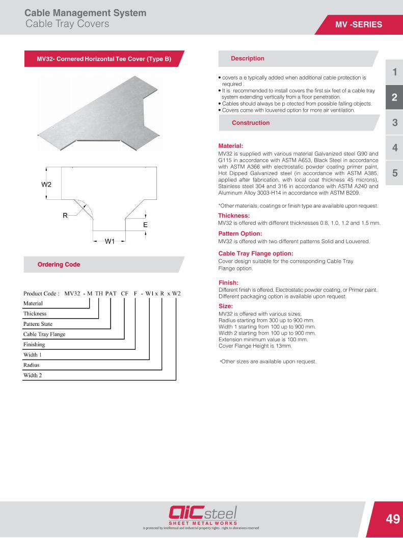
MV32- Cornered Horizontal Tee Cover (Type B) Description
MV32 is supplied with various material Galvanized steel G90 and G115 in accordance with ASTM A653, Black Steel in accordance with ASTM A366 with electrostatic powder coating primer paint, Hot Dipped Galvanized steel (in accordance with ASTM A385, applied after fabrication, with local coat thickness 45 microns), Stainless steel 304 and 316 in accordance with ASTM A240 and Aluminum Alloy 3003-H14 in accordance with ASTM B209.
*Other materials, coatings or fi nish type are available upon request.
Thickness:MV32 is offered with different thicknesses 0.8, 1.0, 1.2 and 1.5 mm.
Pattern Option:MV32 is offered with two different patterns Solid and Louvered.
Material:
Size:
OrOrderdering Codeing Code
Construction
Finish:Different fi nish is offered, Electrostatic powder coating, or Primer paint.Different packaging option is available upon request.
••
•• It is recommended to install covers the fi rst six feet of a cable tray
•• Cables should always be p otected from possible falling objects.•• Covers come with louvered option for more air ventilation.
covers a e typically added when additional cable protection isrequired .
system extending vertically from a fl oor penetration.
*Other sizes are available upon request.
MV32 is offered with various sizes. Radius starting from 300 up to 900 mm. Width 1 starting from 100 up to 900 mm. Width 2 starting from 100 up to 900 mm. Extension minimum value is 100 mm.Cover Flange Height is 13mm.
Cable Tray Flange option:Cover design suitable for the corresponding Cable Tray Flange option.

Cable Management SystemCable Tray Covers
50
3
2
1
is protected by intellectual and industrial property rights . right to alterations reserved
4
5
MV -SERIES
MV33- Cornered Horizontal Tee Cover (Type C)
Ordering Code
Description
MV33 is supplied with various material Galvanized steel G90 and G115 in accordance with ASTM A653, Black Steel in accordance with ASTM A366 with electrostatic powder coating primer paint, Hot Dipped Galvanized steel (in accordance with ASTM A385, applied after fabrication, with local coat thickness 45 microns), Stainless steel 304 and 316 in accordance with ASTM A240 and Aluminum Alloy 3003-H14 in accordance with ASTM B209.
*Other materials, coatings or fi nish type are available upon request.
Thickness:MV33 is offered with different thicknesses 0.8, 1.0, 1.2 and 1.5 mm.
Pattern Option:MV33 is offered with two different patterns Solid and Louvered.
Material:
Finish:
Size:
Ordering Code
Construction
Different fi nish is offered, Electrostatic powder coating, or Primer paint.Different packaging option is available upon request.
• covers are typically added when additional cable protection is
• It is recommended to install covers the fi rst six feet of a cable tray
• Cables should always be protected from possible falling objects.• Covers come with louvered option for more air ventilation.
required .
system extending vertically from a fl oor penetration.
*Other sizes are available upon request.
MV33 is offered with various sizes. Radius starting from 300 up to 900 mm. Width 1 starting from 100 up to 900 mm. Width 2 starting from 100 up to 900 mm. Extension minimum value is 100 mm. Cover Flange Height is 13mm.
Cable Tray Flange option:Cover design suitable for the corresponding Cable Tray Flange option.

Cable Management SystemCable Tray Covers
51
3
2
1
is protected by intellectual and industrial property rights . right to alterations reserved
4
5
MV -SERIES
MV34- Curved Horizontal Tee Cover
Ordering Code
Description
MV34 is supplied with various material Galvanized steel G90 and G115 in accordance with ASTM A653, Black Steel in accordance with ASTM A366 with electrostatic powder coating primer paint, Hot Dipped Galvanized steel (in accordance with ASTM A385, applied after fabrication, with local coat thickness 45 microns), Stainless steel 304 and 316 in accordance with ASTM A240 and Aluminum Alloy 3003-H14 in accordance with ASTM B209.
*Other materials, coatings or fi nish type are available upon request.
Thickness:MV34 is offered with different thicknesses 0.8, 1.0, 1.2 and 1.5 mm.
MV34 is offered with two different patterns Solid and Louvered.
Material:
Pattern Option:
Finish:
Size:
Ordering Code
Construction
Different fi nish is offered, Electrostatic powder coating, or Primer paint.Different packaging option is available upon request.
• covers are typically added when additional cable protection is
• It is recommended to install covers the fi rst six feet of a cable tray
• Cables should always be protected from possible falling objects.• Covers come with louvered option for more air ventilation.
required .
system extending vertically from a fl oor penetration.
*Other sizes are available upon request.
MV34 is offered with various sizes. Radius starting from 300 up to 900 mm. Width 1 starting from 100 up to 900 mm. Width 2 starting from 100 up to 900 mm. Extension minimum value is 100 mm. Cover Flange Height is 10mm.

Cable Management SystemCable Tray Covers
52
3
2
1
is protected by intellectual and industrial property rights . right to alterations reserved
4
5
MV -SERIES
MV41- Cornered Cross Cover (Type A)
Ordering Code
Description
MV41 is supplied with various material Galvanized steel G90 and G115 in accordance with ASTM A653, Black Steel in accordance with ASTM A366 with electrostatic powder coating primer paint, Hot Dipped Galvanized steel (in accordance with ASTM A385, applied after fabrication, with local coat thickness 45 microns), Stainless steel 304 and 316 in accordance with ASTM A240 and Aluminum Alloy 3003-H14 in accordance with ASTM B209.
*Other materials, coatings or fi nish type are available upon request.
MV41 is offered with different thicknesses 0.8, 1.0, 1.2 and 1.5 mm.
MV41 is offered with two different patterns Solid and Louvered.
MV41 is offered with various sizes. Radius starting from 300 up to 900 mm. Width 1 starting from 150 up to 900 mm. Width 2 starting from 150 up to 900 mm.
Material:
Thickness:
Pattern Option:
Finish:
Size:
Construction
Different fi nish is offered, Electrostatic powder coating, or Primer paint.Different packaging option is available upon request.
• covers are typically added when additional cable protection is
• It is recommended to install covers the fi rst six feet of a cable tray
• Cables should always be protected from possible falling objects.• Covers come with louvered option for more air ventilation.
required .
system extending vertically from a fl oor penetration.
*Other sizes are available upon request.
Cover Flange Height is 13mm.
Cable Tray Flange option:Cover design suitable for the corresponding Cable Tray Flange option.

Cable Management SystemCable Tray Covers
53
3
2
1
is protected by intellectual and industrial property rights . right to alterations reserved
4
5
MV -SERIES
MV42- Cornered Cross Cover (Type B)
Ordering Code
Description
MV42 is supplied with various material Galvanized steel G90 and G115 in accordance with ASTM A653, Black Steel in accordance with ASTM A366 with electrostatic powder coating primer paint, Hot Dipped Galvanized steel (in accordance with ASTM A385, applied after fabrication, with local coat thickness 45 microns), Stainless steel 304 and 316 in accordance with ASTM A240 and Aluminum Alloy 3003-H14 in accordance with ASTM B209.
*Other materials, coatings or fi nish type are available upon request.
MV42 is offered with different thicknesses 0.8, 1.0, 1.2 and 1.5 mm.
MV42 is offered with two different patterns Solid and Louvered.
Material:
Thickness:
Pattern Option:
Finish:
Size:
Ordering Code
Construction
Different fi nish is offered, Electrostatic powder coating, or Primer paint.Different packaging option is available upon request.
• covers are typically added when additional cable protection is
• It is recommended to install covers the fi rst six feet of a cable tray
• Cables should always be protected from possible falling objects.• Covers come with louvered option for more air ventilation.
required .
system extending vertically from a fl oor penetration.
*Other sizes are available upon request.
MV42 is offered with various sizes. Radius starting from 300 up to 900 mm. Width 1 starting from 100 up to 900 mm. Width 2 starting from 100 up to 900 mm. Extension minimum value is 100 mm.Cover Flange Height is 13mm.
Cable Tray Flange option:Cover design suitable for the corresponding Cable Tray Flange option.

Cable Management SystemCable Tray Covers
54
3
2
1
is protected by intellectual and industrial property rights . right to alterations reserved
4
5
MV -SERIES
MV43- Cornered Cross Cover (Type C) Description
MV43 is supplied with various material Galvanized steel G90 and G115 in accordance with ASTM A653, Black Steel in accordance with ASTM A366 with electrostatic powder coating primer paint, Hot Dipped Galvanized steel (in accordance with ASTM A385, applied after fabrication, with local coat thickness 45 microns), Stainless steel 304 and 316 in accordance with ASTM A240 and Aluminum Alloy 3003-H14 in accordance with ASTM B209.
*Other materials, coatings or fi nish type are available upon request.
Thickness:MV43 is offered with different thicknesses 0.8, 1.0, 1.2 and 1.5 mm.
Pattern Option:MV43 is offered with two different patterns Solid and Louvered.
Material:
Size:
OrOrderdering Codeing Code
Construction
Finish:Different fi nish is offered, Electrostatic powder coating, or Primer paint.Different packaging option is available upon request.
•
• It is recommended to install covers the fi rst six feet of a cable tray
• Cables should always be protected from possible falling objects.• Covers come with louvered option for more air ventilation.
covers are typically added when additional cable protection isrequired .
system extending vertically from a fl oor penetration.
*Other sizes are available upon request.
MV43 is offered with various sizes. Radius starting from 300 up to 900 mm. Width 1 starting from 100 up to 900 mm. Width 2 starting from 100 up to 900 mm. Extension minimum value is 100 mm. Cover Flange Height is 13mm.
Cable Tray Flange option:Cover design suitable for the corresponding Cable Tray Flange option.

Cable Management SystemCable Tray Covers
55
3
2
1
is protected by intellectual and industrial property rights . right to alterations reserved
4
5
MV -SERIES
MV44- Curved Cross Cover Description
MV44 is supplied with various material Galvanized steel G90 and G115 in accordance with ASTM A653, Black Steel in accordance with ASTM A366 with electrostatic powder coating primer paint, Hot Dipped Galvanized steel (in accordance with ASTM A385, applied after fabrication, with local coat thickness 45 microns), Stainless steel 304 and 316 in accordance with ASTM A240 and Aluminum Alloy 3003-H14 in accordance with ASTM B209.
*Other materials, coatings or fi nish type are available upon request.
Thickness:MV44 is offered with different thicknesses 0.8, 1.0, 1.2 and 1.5 mm.
MV44 is offered with two different patterns Solid and Louvered.
MV44 is offered with various sizes. Radius starting from 300 up to 900 mm. Width 1 starting from 100 up to 900 mm. Width 2 starting from 100 up to 900 mm. Extension minimum value is 100 mm.
Material:
Pattern Option:
Size:
OrOrderdering Codeing Code
Construction
Finish:Different fi nish is offered, Electrostatic powder coating, or Primer paint.Different packaging option is available upon request.
••
•• It is recommended to install covers the fi rst six feet of a cable tray
•• Cables should always be p otected from possible falling objects.•• Covers come with louvered option for more air ventilation.
covers a e typically added when additional cable protection isrequired .
system extending vertically from a fl oor penetration.
*Other sizes are available upon request.
Cover Flange Height is 10mm.

Cable Management SystemCable Tray Covers
56
3
2
1
is protected by intellectual and industrial property rights . right to alterations reserved
4
5
MV -SERIES
MV51- Central Cornered Reducer Cover (Type A) Description
MV51 is supplied with various material Galvanized steel G90 and G115 in accordance with ASTM A653, Black Steel in accordance with ASTM A366 with electrostatic powder coating primer paint, Hot Dipped Galvanized steel (in accordance with ASTM A385, applied after fabrication, with local coat thickness 45 microns), Stainless steel 304 and 316 in accordance with ASTM A240 and Aluminum Alloy 3003-H14 in accordance with ASTM B209.
*Other materials, coatings or fi nish type are available upon request.
Thickness:MV51 is offered with different thicknesses 0.8, 1.0, 1.2 and 1.5 mm.
Pattern Option:MV51 is offered with two different patterns Solid and Louvered.
MV51 is offered with various sizes.Width 1 starting from 150 up to 900 mm. Width 2 starting from 150 up to 900 mm. Length is 300 mm.
Material:
Size:
OrOrderdering Codeing Code
Construction
Finish:Different fi nish is offered, Electrostatic powder coating, or Primer paint.Different packaging option is available upon request.
••
•• It is recommended to install covers the fi rst six feet of a cable tray
•• Cables should always be p otected from possible falling objects.•• Covers come with louvered option for more air ventilation.
covers a e typically added when additional cable protection isrequired .
system extending vertically from a fl oor penetration.
*Other sizes are available upon request.
Cover Flange Height is 13mm.
Cable Tray Flange option:Cover design suitable for the corresponding Cable Tray Flange option.

Cable Management SystemCable Tray Covers
57
3
2
1
is protected by intellectual and industrial property rights . right to alterations reserved
4
5
MV -SERIES
MV52- Central Cornered Reducer Cover (Type B) Description
MV52 is supplied with various material Galvanized steel G90 and G115 in accordance with ASTM A653, Black Steel in accordance with ASTM A366 with electrostatic powder coating primer paint, Hot Dipped Galvanized steel (in accordance with ASTM A385, applied after fabrication, with local coat thickness 45 microns), Stainless steel 304 and 316 in accordance with ASTM A240 and Aluminum Alloy 3003-H14 in accordance with ASTM B209.
*Other materials, coatings or fi nish type are available upon request.
Thickness:MV52 is offered with different thicknesses 0.8, 1.0, 1.2 and 1.5 mm.
Pattern Option:MV52 is offered with two different patterns Solid and Louvered.
Material:
Size:
OrOrderdering Codeing Code
Construction
Finish:Different fi nish is offered, Electrostatic powder coating, or Primer paint.Different packaging option is available upon request.
••
•• It is recommended to install covers the fi rst six feet of a cable tray
•• Cables should always be p otected from possible falling objects.•• Covers come with louvered option for more air ventilation.
covers a e typically added when additional cable protection isrequired .
system extending vertically from a fl oor penetration.
*Other sizes are available upon request.
MV52 is offered with various sizes. Width 1 starting from 100 up to 900 mm. Width 2 starting from 100 up to 900 mm. Extension minimum value is 100 mm.Length is 500 mm minimum.Cover Flange Height is 13mm.
Cable Tray Flange option:Cover design suitable for the corresponding Cable Tray Flange option.

Cable Management SystemCable Tray Covers
58
3
2
1
is protected by intellectual and industrial property rights . right to alterations reserved
4
5
MV -SERIES
MV53- Central Cornered Reducer Cover (Type C)
Ordering Code
Description
MV53 is supplied with various material Galvanized steel G90 and G115 in accordance with ASTM A653, Black Steel in accordance with ASTM A366 with electrostatic powder coating primer paint, Hot Dipped Galvanized steel (in accordance with ASTM A385, applied after fabrication, with local coat thickness 45 microns), Stainless steel 304 and 316 in accordance with ASTM A240 and Aluminum Alloy 3003-H14 in accordance with ASTM B209.
*Other materials, coatings or fi nish type are available upon request.
Thickness:MV53 is offered with different thicknesses 0.8, 1.0, 1.2 and 1.5 mm.
Pattern Option:MV53 is offered with two different patterns Solid and Louvered.
Material:
Finish:
Size:
Ordering Code
Construction
Different fi nish is offered, Electrostatic powder coating, or Primer paint.Different packaging option is available upon request.
• covers are typically added when additional cable protection is
• It is recommended to install covers the fi rst six feet of a cable tray
• Cables should always be protected from possible falling objects.• Covers come with louvered option for more air ventilation.
required .
system extending vertically from a fl oor penetration.
*Other sizes are available upon request.
MV53 is offered with various sizes.Width 1 starting from 150 up to 900 mm. Width 2 starting from 150 up to 900 mm. Extension minimum value is 100 mm. Length is 500 mm minimum.Cover Flange Height is 13mm.
Cable Tray Flange option:Cover design suitable for the corresponding Cable Tray Flange option.

Cable Management SystemCable Tray Covers
59
3
2
1
is protected by intellectual and industrial property rights . right to alterations reserved
4
5
MV -SERIES
MV61- Side Cornered Reducer Cover (Type A)
Ordering Code
Description
MV61 is supplied with various material Galvanized steel G90 and G115 in accordance with ASTM A653, Black Steel in accordance with ASTM A366 with electrostatic powder coating primer paint, Hot Dipped Galvanized steel (in accordance with ASTM A385, applied after fabrication, with local coat thickness 45 microns), Stainless steel 304 and 316 in accordance with ASTM A240 and Aluminum Alloy 3003-H14 in accordance with ASTM B209.
*Other materials, coatings or fi nish type are available upon request.
Thickness:MV61 is offered with different thicknesses 0.8, 1.0, 1.2 and 1.5 mm.
Pattern Option:MV61 is offered with two different patterns Solid and Louvered.
Reducer Type:MV61 is offered with two different reducer Right and Left.
Material:
Finish:
Size:
Ordering Code
Construction
Different fi nish is offered, Electrostatic powder coating, or Primer paint.Different packaging option is available upon request.
• covers are typically added when additional cable protection is
• It is recommended to install covers the fi rst six feet of a cable tray
• Cables should always be protected from possible falling objects.• Covers come with louvered option for more air ventilation.
required .
system extending vertically from a fl oor penetration.
*Other sizes are available upon request.
MV61 is offered with various sizes.Width 1 starting from 100 up to 900 mm. Width 2 starting from 100 up to 900 mm. Length is 300 mm. Cover Flange Height is 13mm.
Cable Tray Flange option:Cover design suitable for the corresponding Cable Tray Flange option.

Cable Management SystemCable Tray Covers
60
3
2
1
is protected by intellectual and industrial property rights . right to alterations reserved
4
5
MV -SERIES
MV62- Side Cornered Reducer Cover (Type B)
Ordering Code
Description
MV62 is supplied with various material Galvanized steel G90 and G115 in accordance with ASTM A653, Black Steel in accordance with ASTM A366 with electrostatic powder coating primer paint, Hot Dipped Galvanized steel (in accordance with ASTM A385, applied after fabrication, with local coat thickness 45 microns), Stainless steel 304 and 316 in accordance with ASTM A240 and Aluminum Alloy 3003-H14 in accordance with ASTM B209.
*Other materials, coatings or fi nish type are available upon request.
Thickness:MV62 is offered with different thicknesses 0.8, 1.0, 1.2 and 1.5 mm.
Pattern Option:MV62 is offered with two different patterns Solid and Louvered.
Reducer Type:MV62 is offered with two different reducer Right and Left.
Material:
Finish:
Ordering Code
Construction
Different fi nish is offered, Electrostatic powder coating, or Primer paint.Different packaging option is available upon request.
• covers are typically added when additional cable protection is
• It is recommended to install covers the fi rst six feet of a cable tray
• Cables should always be protected from possible falling objects.• Covers come with louvered option for more air ventilation.
required .
system extending vertically from a fl oor penetration.
*Other sizes are available upon request.
Size:MV62 is offered with various sizes. Width 1 starting from 100 up to 900 mm. Width 2 starting from 100 up to 900 mm. Extension minimum value is 100 mm. Length is 500 mm minimum.Cover Flange Height is 13mm.
Cable Tray Flange option:Cover design suitable for the corresponding Cable Tray Flange option.

Cable Management SystemCable Tray Covers
61is protected by intellectual and industrial property rights . right to alterations reserved
MV63- Side Cornered Reducer Cover (Type C) Description
MV63 is supplied with various material Galvanized steel G90 and G115 in accordance with ASTM A653, Black Steel in accordance with ASTM A366 with electrostatic powder coating primer paint, Hot Dipped Galvanized steel (in accordance with ASTM A385, applied after fabrication, with local coat thickness 45 microns), Stainless steel 304 and 316 in accordance with ASTM A240 and Aluminum Alloy 3003-H14 in accordance with ASTM B209.
*Other materials, coatings or fi nish type are available upon request.
Thickness:MV63 is offered with different thicknesses 0.8, 1.0, 1.2 and 1.5 mm.
Pattern Option:MV63 is offered with two different patterns Solid and Louvered.
Reducer Type:MV63 is offered with two different reducer Right and Left.
Material:
Finish:
OrOrderdering Codeing Code
Construction
Different fi nish is offered, Electrostatic powder coating, or Primer paint.Different packaging option is available upon request.
••
•• It is recommended to install covers the fi rst six feet of a cable tray
•• Cables should always be p otected from possible falling objects.•• Covers come with louvered option for more air ventilation.
covers a e typically added when additional cable protection isrequired .
system extending vertically from a fl oor penetration.
*Other sizes are available upon request.
Size:MV63 is offered with various sizes. Width 1 starting from 100 up to 900 mm. Width 2 starting from 100 up to 900 mm. Extension minimum value is 100 mm. Length is 500 mm minimum.Cover Flange Height is 13mm.
Cable Tray Flange option:Cover design suitable for the corresponding Cable Tray Flange option.
3
2
1
4
5

MV -SERIES
SystemAccessories

MV -SERIES

Cable Management SystemSystem Accessories
64
3
2
1
is protected by intellectual and industrial property rights . right to alterations reserved
4
5
MA -SERIES
Bolts, Nuts and Washers Description
MA01 MA02 MA03 MA04 MA05 MA06 MA07MA08MA09
Electroplating galvanized Carriage bolts, DIN 603. Electroplating galvanized bolts, DIN 933, DIN 6921, DIN 7045 Electroplating galvanized nuts, DIN 934, DIN 6923. Electroplating galvanized washer, DIN 125-1A, DIN 128. Hot dipped galvanized Carriage bolts, DIN 603.Hot dipped galvanized bolts, DIN 933, DIN 6921, DIN 7045. Hot dipped galvanized nuts, DIN 934, DIN 6923. Hot dipped galvanized washers, DIN 125-1A, DIN 128.Stainless steel Carriage bolts, DIN 603.Stainless steel 304 bolts, DIN 933, DIN 6921, DIN 7045. Stainless steel 304 nuts, DIN 934, DIN 6923.Stainless steel 304 washers, DIN 125-1A, DIN 128.
MA23 are supplied with various material Galvanized steel. G90 accordance with ASTM A653 and Stainless steel 304 in accordance with ASTM A240.
MA23 are supplied with different diameters (M6, M8, M10, M12, M16 and M20).
*Available length is 3 meters.
MA23- THREADED RODS
MA24-Angle Bars
MA29- ADHESIVE TAPES
MA29 are one side self-adhesive used to cover
the separation between two cable tray covers.
1 - GASKT-ADH_TAPE-AL-48mm X 50 Yard 2 - GASKT-ADH_TAPE-48mm X 50 Yard
Description
Description
Description
MA24 are supplied with various material Galvanized
steel G90 accordance with ASTM A653 and Stainless steel 304 in accordance with ASTM A240.MA24 are supplied with oblong (cut) 30x12 equally spaced
150mm along the length.MA24 are supplied with different sizes:
- 25x25x2.5 and 3.0mm- 30x30x3.0 mm- 40x40x3.0 and 4.0mm- 50x50x3.0, 4.0 and 5.0 mm- 60x60x5.0 and 6.0 mm
Available length is 3 meters*
MA10MA11MA12

Cable Management SystemSystem Accessories
65
3
2
1
is protected by intellectual and industrial property rights . right to alterations reserved
4
5
MA -SERIES
• Used when cable separation is needed, as required by the National Electrical Code (NEC).
MA61- Fish Plate
Ordering Code
Description
• Used for Straight connection between cable tray.
MA61 is supplied with various material Galvanized steel G90 and G115 in accordance with ASTM A653, Black Steel in accordance with ASTM A366 with electrostatic powder coating primer paint, Hot Dipped Galvanized steel (in accordance with ASTM A385, applied after fabrication, with local coat thickness 45 microns), Stainless steel 304 and 316 in accordance with ASTM A240 and Aluminum Alloy 3003-H14 in accordance with ASTM B209.
*Other materials, coatings or fi nish type are available upon request.
MA61 is offered with different thicknesses - from Ga. 20 (1.0 mm) to Ga. 13 (2.5 mm).
Material:
Thickness:
Finish:
Construction
Different fi nish is offered, Electrostatic powder coating, or Primer paint.Different packaging option is available upon request.
Size:MA61 is offered with various sizes.Width starting from 200 up to 900 mm,and with different lengths according to the below table:
*Other sizes are available upon request.
Length "L" (mm) Spacing "S" (mm)
90 50
110 85
140 100

Cable Management SystemSystem Accessories
66
3
2
1
is protected by intellectual and industrial property rights . right to alterations reserved
4
5
MA -SERIES
MA62- Expansion Joint
Ordering Code
Description
• MA62, Expansion joint is designed to help the system withstand thethermal expansion (due to temperature difference) considering the weather in the region throughout the year.
MA62 is supplied with various material Galvanized steel G90 and G115 in accordance with ASTM A653, Black Steel in accordance with ASTM A366 with electrostatic powder coating primer paint, Hot Dipped Galvanized steel (in accordance with ASTM A385, applied after fabrication, with local coat thickness 45 microns), Stainless steel 304 and 316 in accordance with ASTM A240 and Aluminum Alloy 3003-H14 in accordance with ASTM B209.
*Other materials, coatings or fi nish type are available upon request.
MA62 is offered with different thicknesses -from Ga. 20 (1.0 mm) to Ga. 13 (2.5 mm).
Size:MA62 is offered with various sizes.Height starting from 25 up to 150 mm,and with different lengths according to the below table:
*Other sizes are available upon request.
Material:
Thickness:
Finish:
Construction
Different fi nish is offered, Electrostatic powder coating, or Primer paint.Different packaging option is available upon request.
Length "L" (mm) Spacing "S" (mm)
140 50
180 90
190 100

Cable Management SystemSystem Accessories
67
3
2
1
is protected by intellectual and industrial property rights . right to alterations reserved
4
5
MA -SERIES
For changes in Horizontal direction that not requiring a large radius, MA63 can be used.
MA63- Adjustable Horizontal Connector
Ordering Code
Description
•
• Designed to maximize the rigidity of the cable tray.
• Angle less than 30 degrees.
MA63 is supplied with various material Galvanized steel G90 and G115 in accordance with ASTM A653, Black Steel in accordance with ASTM A366 with electrostatic powder coating primer paint, Hot Dipped Galvanized steel (in accordance with ASTM A385, applied after fabrication, with local coat thickness 45 microns), Stainless steel 304 and 316 in accordance with ASTM A240 and Aluminum Alloy 3003-H14 in accordance with ASTM B209.
*Other materials, coatings or fi nish type are available upon request.
MA63 is offered with different thicknesses -from Ga. 20 (1.0 mm) to Ga. 13 (2.5 mm).
MA63 is offered with various sizes suitable for cable tray height starting from 25 up to 150 mm.
*Other sizes are available upon request.
Material:
Thickness:
Finish:
Size:
Construction
Different fi nish is offered, Electrostatic powder coating, or Primer paint.Different packaging option is available upon request.
• Hinge Rod 5 mm diameter

Cable Management SystemSystem Accessories
68
3
2
1
is protected by intellectual and industrial property rights . right to alterations reserved
4
5
MA -SERIES
MA64- Adjustable Vertical Connector
Ordering Code
Description
• For changes in Vertical direction not requiring a large radius, MA64
• designed to maximize the rigidity of the cable tray.• Angle less than 30 degree.
can be used.
MA64 is supplied with various material Galvanized steel G90 and G115 in accordance with ASTM A653, Black Steel in accordance with ASTM A366 with electrostatic powder coating primer paint, Hot Dipped Galvanized steel (in accordance with ASTM A385, applied after fabrication, with local coat thickness 45 microns), Stainless steel 304 and 316 in accordance with ASTM A240 and Aluminum Alloy 3003-H14 in accordance with ASTM B209.
*Other materials, coatings or fi nish type are available upon request.
MA64 is offered with different thicknesses -from Ga. 20 (1.0 mm) to Ga. 13 (2.5 mm).
Size:MA64 is offered with various sizes suitable for cable tray height starting from 25 up to 150 mm.
*Other sizes are available upon request.
Material:
Thickness:
Finish:
Construction
Different fi nish is offered, Electrostatic powder coating, or Primer paint.Different packaging option is available upon request.

Cable Management SystemSystem Accessories
69
3
2
1
is protected by intellectual and industrial property rights . right to alterations reserved
4
5
MA -SERIES
MA66- L-Angle connector
Ordering Code
Description
• Connect two trays from both side and bottom with bolts.
MA66 is supplied with various material Galvanized steel G90 and G115 in accordance with ASTM A653, Black Steel in accordance with ASTM A366 with electrostatic powder coating primer paint, Hot Dipped Galvanized steel (in accordance with ASTM A385, applied after fabrication, with local coat thickness 45 microns), Stainless steel 304 and 316 in accordance with ASTM A240 and Aluminum Alloy 3003-H14 in accordance with ASTM B209.
*Other materials, coatings or fi nish type are available upon request.
MA66 is offered with different thicknesses -from Ga. 20 (1.0 mm) to Ga. 13 (2.5 mm).
Material:
Thickness:
Finish:
Construction
Different fi nish is offered, Electrostatic powder coating, or Primer paint.Different packaging option is available upon request.
Size:MA66 is offered with various sizes.Height starting from 25 up to 150 mm,Flange widths 25 mm ,40 mm and 65 mm. and with different lengths according to the below table:
*Other sizes are available upon request.
Length "L" (mm) Spacing "S" (mm)
185 50
225 90
235 100

Cable Management SystemSystem Accessories
70
3
2
1
is protected by intellectual and industrial property rights . right to alterations reserved
4
5
MA -SERIES
MA71- C-Clamp
Ordering Code
Description
• Used for cover assembly with tray body.
MA71 is supplied with various material Galvanized steel G90 and G115 in accordance with ASTM A653, Black Steel in accordance with ASTM A366 with electrostatic powder coating primer paint, Hot Dipped Galvanized steel (in accordance with ASTM A385, applied after fabrication, with local coat thickness 45 microns), Stainless steel 304 and 316 in accordance with ASTM A240 and Aluminum Alloy 3003-H14 in accordance with ASTM B209.
*Other materials, coatings or fi nish type are available upon request.
• Default thickness is 2mm, other thicknesses are available upon request.
Size:MA71 is offered with various sizes suitable for cable tray height starting from 25 up to 150 mm.
Material:
Thickness:
Finish:
Construction
Different fi nish is offered, Electrostatic powder coating, or Primer paint.Different packaging option is available upon request.
MA71 is available with two threaded hole sizes M5 and M6Threaded Hole:
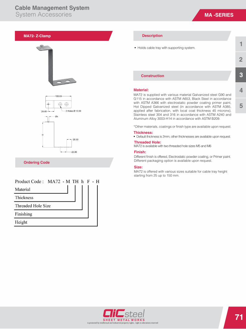
Cable Management SystemSystem Accessories
71
3
2
1
is protected by intellectual and industrial property rights . right to alterations reserved
4
5
MA -SERIES
• Default thickness is 2mm, other thicknesses are available upon request.
MA72- Z-Clamp
Ordering Code
Description
• Holds cable tray with supporting system.
MA72 is supplied with various material Galvanized steel G90 and G115 in accordance with ASTM A653, Black Steel in accordance with ASTM A366 with electrostatic powder coating primer paint, Hot Dipped Galvanized steel (in accordance with ASTM A385, applied after fabrication, with local coat thickness 45 microns), Stainless steel 304 and 316 in accordance with ASTM A240 and Aluminum Alloy 3003-H14 in accordance with ASTM B209.
*Other materials, coatings or fi nish type are available upon request.
Size:MA72 is offered with various sizes suitable for cable tray height starting from 25 up to 150 mm.
Material:
Thickness:
Finish:
Construction
Different fi nish is offered, Electrostatic powder coating, or Primer paint.Different packaging option is available upon request.
MA72 is available with two threaded hole sizes M5 and M6Threaded Hole:

Cable Management SystemSystem Accessories
72
3
2
1
is protected by intellectual and industrial property rights . right to alterations reserved
4
5
MA -SERIES
MA81- Single C-Channel (Strut)
Ordering Code
Description
• Used in supporting system with three option to provide high strength.• Plain-Ribbed-Toothed.
MA81 is supplied with various material Galvanized steel G90 and G115 in accordance with ASTM A653, Black Steel in accordance with ASTM A366 with electrostatic powder coating primer paint, Hot Rolled Black Steel in accordance with ASTM-A36 with electrostatic powder coating primer paint, Hot Dipped Galvanized steel (in accordance with ASTM A385, applied after fabrication, with local coat thickness 45 microns), Stainless steel 304 and 316 in accordance with ASTM A240 and Aluminum Alloy 3003-H14 in accordance with ASTM B209.*Other materials, coatings or fi nish type are available upon request.
MA81 is offered with different thicknesses -from Ga. 20 (1.0 mm) to Ga. 13 (2.5 mm).
Flange Option:MA81 is offered with different two optio toothless flange and toothed flange for spring nut fixation.
MA81 is offered with various sizes Width is 41 mm.Height starting from 21, 41 and 61 mm. Length starting from 200 up to 4000 mm.
*Other sizes are available upon request.
MA81 is offered with two different options plain for moderate load and ribbed option for heavy load. .
MA81 is offered with two different options solid and slotted with two different slot size (11X25) & (13X30).
Material:
Thickness:
Finish:
Size:
Corrugation Option:
Slot Option:
Construction
Different fi nish is offered, Electrostatic powder coating, or Primer paint.Different packaging option is available upon request.

Cable Management SystemSystem Accessories
73
3
2
1
is protected by intellectual and industrial property rights . right to alterations reserved
4
5
MA -SERIES
Description
•
MA82 is supplied with various material Galvanized steel G90 and G115 in accordance with ASTM A653, Black Steel in accordance with ASTM A366 with electrostatic powder coating primer paint, Hot Rolled Black Steel in accordance with ASTM-A36 with electrostatic powder coating primer paint, Hot Dipped Galvanized steel (in accordance with ASTM A385, applied after fabrication, with local coat thickness 45 microns), Stainless steel 304 and 316 in accordance with ASTM A240 and Aluminum Alloy 3003-H14 in accordance with ASTM B209.
*Other materials, coatings or fi nish type are available upon request.
MA82 is offered with different thicknesses -from Ga. 20 (1.0 mm) to Ga. 13 (2.5 mm).
Flange Option:MA82 is offered with different two option toothless flange and toothed flange for spring nut fixation.
MA82 is offered with various sizesWidth is 51 mm.Strut Heights are 21, 41 and 61 mm.Bracket Height are 80, 100 and 120 mm. Length starting from 150 up to 1000 mm.
*Other sizes are available upon request.
MA82 is offered with two different options plain for moderate load and ribbed option for heavy load.
MA82 is offered with two different options solid and slotted with two different slot size (11X25) & (13X30) mm.
Material:
Thickness:
Finish:
Size:
Corrugation Option:
Slot Option:
Construction
MA82- Single Cantilever
Ordering Code
Different fi nish is offered, Electrostatic powder coating, or Primer paint.Different packaging option is available upon request.
Used in supporting system to hold cable tray to nearest wall (wall-mounting)

Cable Management SystemSystem Accessories
74
3
2
1
is protected by intellectual and industrial property rights . right to alterations reserved
4
5
MA -SERIES
MA83- Double C-Channel (Strut)
Ordering Code
Description
• Used in supporting system with three option to provide high strength• Plain-Ribbed-Toothed.• Can endure higher loads.
MA83 is supplied with various material Galvanized steel G90 and G115 in accordance with ASTM A653, Black Steel in accordance with ASTM A366 with electrostatic powder coating primer paint, Hot Rolled Black Steel in accordance with ASTM-A36 with electrostatic powder coating primer paint, Hot Dipped Galvanized steel (in accordance with ASTM A385, applied after fabrication, with local coat thickness 45 microns), Stainless steel 304 and 316 in accordance with ASTM A240 and Aluminum Alloy 3003-H14 in accordance with ASTM B209.
*Other materials, coatings or fi nish type are available upon request.
MA83 is offered with different thicknesses -from Ga. 20 (1.0 mm) to Ga. 13 (2.5 mm).
Flange Option:MA83 is offered with different two option toothless flange and toothed flange for spring nut fixation.
MA83 is offered with various sizes Width is 41 mm.Height starting from 42, 82 and 122 mm.Length starting from 200 up to 4000 mm
*Other sizes are available upon request.
MA83 is offered with two different options plain for moderate load and ribbed option for heavy load.
MA83 is offered with two different options solid and slotted with two different slot size (11X25) & (13X30).
Material:
Thickness:
Finish:
Size:
Corrugation Option:
Slot Option:
Construction
Different fi nish is offered, Electrostatic powder coating, or Primer paint.Different packaging option is available upon request.

Cable Management SystemSystem Accessories
75
3
2
1
is protected by intellectual and industrial property rights . right to alterations reserved
4
5
MA -SERIES
Description
• Used in supporting system to hold cable tray to nearest wall (wall-mounting)• Can endure higher loads.
MA84 is supplied with various material Galvanized steel G90 and G115 in accordance with ASTM A653, Black Steel in accordance with ASTM A366 with electrostatic powder coating primer paint, Hot Rolled Black Steel in accordance with ASTM-A36 with electrostatic powder coating primer paint, Hot Dipped Galvanized steel (in accordance with ASTM A385, applied after fabrication, with local coat thickness 45 microns), Stainless steel 304 and 316 in accordance with ASTM A240 and Aluminum Alloy 3003-H14 in accordance with ASTM B209.
*Other materials, coatings or fi nish type are available upon request.
Thickness:MA84 is offered with different thicknesses -from Ga. 20 (1.0 mm) to Ga. 13 (2.5 mm).
Flange Option:MA84 is offered with different two option toothless flange and toothed flange for spring nut fixation.
MA84 is offered with various sizesWidth is 51 mm.Strut Heights are 21, 41 and 61 mm.Bracket Height varies from 100 mm up to 180 mm.Length starting from 200 up to 1000 mm.
*Other sizes are available upon request.
Corrugation Option:MA84 is offered with two different options plain for moderate load and ribbed option for heavy load.
Slot Option:MA84 is offered with two different options solid and slotted with two different slot size (11X25) & (13X30) mm.
Material:
Finish:
Size:
Construction
MA84- Double Cantilever Arm
Ordering Code
Different fi nish is offered, Electrostatic powder coating, or Primer paint.Different packaging option is available upon request.

Cable Management SystemSystem Accessories
76
3
2
1
is protected by intellectual and industrial property rights . right to alterations reserved
4
5
MA -SERIES
MA91- Earthing Jumper
Ordering Code
Description
• Used for grounding cable tray.
MA91 is offered with different cable cross section area sizes start from 4 mm² to 20 mm² based on agreed schedule.
MA91 is offered with 6.5 mm stud hole size.
MA82 is offered with length starting from 100 up to 300 mm.
Cable Size:
Stud Hole:
Length:
Construction

Cable Management SystemSystem Accessories
77
3
2
1
is protected by intellectual and industrial property rights . right to alterations reserved
4
5
MA -SERIES
Description
• To connect two cable trays with two different widths.
MA92 is supplied with various material Galvanized steel G90 and G115 in accordance with ASTM A653, Black Steel in accordance with ASTM A366 with electrostatic powder coating primer paint, Hot Dipped Galvanized steel (in accordance with ASTM A385, applied after fabrication, with local coat thickness 45 microns), Stainless steel 304 and 316 in accordance with ASTM A240 and Aluminum Alloy 3003-H14 in accordance with ASTM B209.
*Other materials, coatings or fi nish type are available upon request.
MA92 is offered with different thicknesses -from Ga. 20 (1.0 mm) to Ga. 13 (2.5 mm).
MA92 is offered with various sizes.Width 1 starting from 100 up to 900 mm.Height starting from 25 up to 150 mm.Width 2 starting from 100 up to 900 mm.
*Other sizes are available upon request.
Material:
Thickness:
Finish:
Size:
Construction
MA92- Sharp Reducer
Ordering Code
Different fi nish is offered, Electrostatic powder coating, or Primer paint.Different packaging option is available upon request.
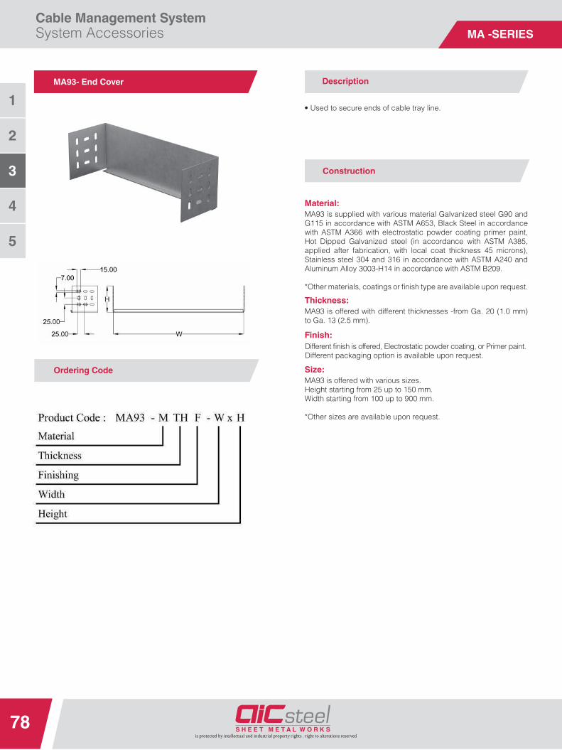
Cable Management SystemSystem Accessories
78
3
2
1
is protected by intellectual and industrial property rights . right to alterations reserved
4
5
MA -SERIES
Description
• Used to secure ends of cable tray line.
MA93 is supplied with various material Galvanized steel G90 and G115 in accordance with ASTM A653, Black Steel in accordance with ASTM A366 with electrostatic powder coating primer paint, Hot Dipped Galvanized steel (in accordance with ASTM A385, applied after fabrication, with local coat thickness 45 microns), Stainless steel 304 and 316 in accordance with ASTM A240 and Aluminum Alloy 3003-H14 in accordance with ASTM B209.
*Other materials, coatings or fi nish type are available upon request.
MA93 is offered with different thicknesses -from Ga. 20 (1.0 mm) to Ga. 13 (2.5 mm).
MA93 is offered with various sizes.Height starting from 25 up to 150 mm.Width starting from 100 up to 900 mm.
*Other sizes are available upon request.
Material:
Thickness:
Finish:
Size:
Construction
MA93- End Cover
Ordering Code
Different fi nish is offered, Electrostatic powder coating, or Primer paint.Different packaging option is available upon request.

Cable Management SystemSystem Accessories
79
3
2
1
is protected by intellectual and industrial property rights . right to alterations reserved
4
5
MA -SERIES
Description
• The drop-outs provide a smooth surface to protect the cableinsulation as it exits the cable tray.
MA94 is supplied with various material Galvanized steel G90 and G115 in accordance with ASTM A653, Black Steel in accordance with ASTM A366 with electrostatic powder coating primer paint, Hot Dipped Galvanized steel (in accordance with ASTM A385, applied after fabrication, with local coat thickness 45 microns), Stainless steel 304 and 316 in accordance with ASTM A240 and Aluminum Alloy 3003-H14 in accordance with ASTM B209.
*Other materials, coatings or fi nish type are available upon request.
MA94 is offered with different thicknesses -from Ga. 20 (1.0 mm) to Ga. 13 (2.5 mm).
MA94 is offered with various sizes.Width starting from 100 up to 900 mm.
*Other sizes are available upon request.
Material:
Thickness:
Finish:
Size:
Construction
MA94- Drop out Plate
Ordering Code
Different fi nish is offered, Electrostatic powder coating, or Primer paint.Different packaging option is available upon request.
*R= 100 mm

MA -SERIES
Cable Tray Construction

MA -SERIES

Cable Management SystemCable Tray Construction
82
3
4
2
1
is protected by intellectual and industrial property rights . right to alterations reserved
5
Cable Tray Construction-Schematic
1 Straight Cable Tray 2 Central Reducer 3 Straight Cable Tray (Roll formed)
4 Adjustable Vertical Connector 5 Cross 6 Expansion Joint
7 Horizontal Bend 8 Tee Branch 9 Outside Riser
10 Inside Riser 11 Outside Riser 12 End Cover
13 Horizontal Bend 14 Drop Out 15 Fish Plate
Assembly

Cable Management SystemCable Tray Construction
83
3
4
2
1
is protected by intellectual and industrial property rights . right to alterations reserved
5
Fish Plate
Cornered Bend
Cover
Expansion Joint
Reducer
End cover
Attach Fish Plate to the cable tray bottom
Insert the Expansion joint and fish plate, screw them to the cable tray, then attach the cornered bend.
Fasten the C- Clamp from the outside onto the cable tray, place the cover and screw.
Push the Expansion Joint into the cable tray side rail, screw each side rail tights using screw, then push in the connecting tray and screw to the expansion joint.
Insert cable tray reducer and L angle connector into the cable tray and screw together in one place perside rail.
Insert tray end cover at the end of cable trays and screw it to the side rail.
Instructions

Cable Management System Cable Tray Construction
84is protected by intellectual and industrial property rights . right to alterations reserved
Testing
3
4
2
1
5
1 joint position withing each span. 2 Cable Tray Standard Length. 3 End span = L .
4 Intermediate span = L. 5 Cantilever = 0.4L. 6 Support positions.
d End of load. e measuring point 1 f measuring point 2
Safe working Load Test - General Arrangement
Load Tests carried out according to IEC 61537:2006 and complying with NEMA.
The loads shown on all tables are the safe recommended maximum loads that can be applied and must include wind, snow and any
other external forces in addition to the cables load.The Tables from page no. 85 up to page no. 93 showing the maximum load for tray installed at a support spacing within different ranges
from 1.0 meters up to 3.0 meters.
Illustrative Drawings for Testing Load Application.
Safe working Load Test - General Arrangement

Cable Management System Cable Tray Construction
is protected by intellectual and industrial property rights . right to alterations reserved
85
3
4
2
1
5
Cable Tray Safe Working Load
SWL

Cable Management SystemCable Tray Construction
86
3
4
2
1
is protected by intellectual and industrial property rights . right to alterations reserved
5
MC01- Straight Cable Tray- Flange Height 25 mm
MC01- Straight Cable Tray- Flange Height 50 mm
MC01- Straight Cable Tray- Flange Height 75 mm
Thickness : 1.0 mmLength : 300 – 3000 mm
Thickness : 1.0 mmLength : 300 – 3000 mm
Thickness : 1.0 mmLength : 300 – 3000 mm
Light DutyLight DutyLight Duty

Cable Management SystemCable Tray Construction
87
3
4
2
1
is protected by intellectual and industrial property rights . right to alterations reserved
5
MC01- Straight Cable Tray- Flange Height 25 mm
MC01- Straight Cable Tray- Flange Height 50 mm
MC01- Straight Cable Tray- Flange Height 75 mm
Thickness : 1.2 mmLength : 300 – 3000 mm
Thickness : 1.2 mmLength : 300 – 3000 mm
Thickness : 1.2 mmLength : 300 – 3000 mm
Medium DutyMedium DutyMedium Duty

Cable Management SystemCable Tray Construction
88
3
4
2
1
is protected by intellectual and industrial property rights . right to alterations reserved
5
MC01- Straight Cable Tray- Flange Height 100 mm
MC01- Straight Cable Tray- Flange Height 150 mm
Thickness : 1.2 mmLength : 300 – 3000 mm
Thickness : 1.2 mmLength : 300 – 3000 mm
Medium Duty

Cable Management SystemCable Tray Construction
89
3
4
2
1
is protected by intellectual and industrial property rights . right to alterations reserved
5
MC01- Straight Cable Tray- Flange Height 50 mm
MC01- Straight Cable Tray- Flange Height 75 mm
MC01- Straight Cable Tray- Flange Height 100 mm
Thickness : 1.5 mmLength : 300 – 3000 mm
Thickness : 1.5 mmLength : 300 – 3000 mm
Thickness : 1.5 mmLength : 300 – 3000 mm
Heavy Duty

Cable Management SystemCable Tray Construction
90
3
4
2
1
is protected by intellectual and industrial property rights . right to alterations reserved
5
MC01- Straight Cable Tray- Flange Height 150 mm
Thickness : 1.5 mmLength : 300 – 3000 mm
Heavy Duty
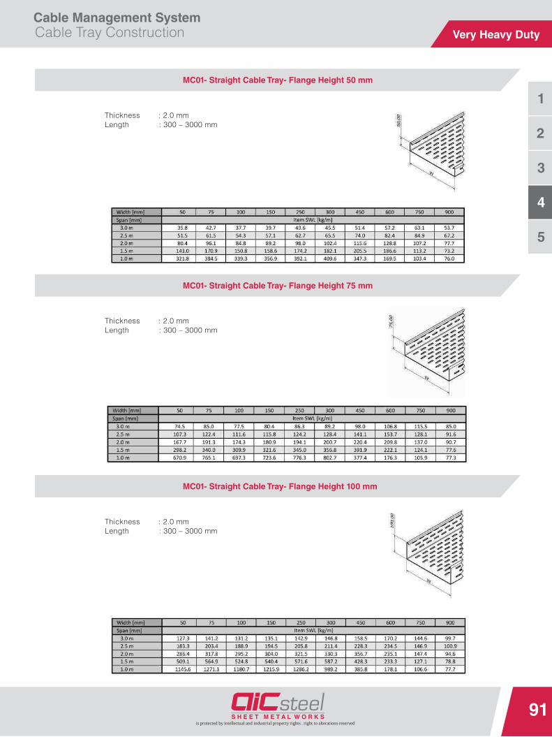
Cable Management SystemCable Tray Construction
91
3
4
2
1
is protected by intellectual and industrial property rights . right to alterations reserved
5
MC01- Straight Cable Tray- Flange Height 50 mm
MC01- Straight Cable Tray- Flange Height 75 mm
MC01- Straight Cable Tray- Flange Height 100 mm
Thickness : 2.0 mmLength : 300 – 3000 mm
Thickness : 2.0 mmLength : 300 – 3000 mm
Thickness : 2.0 mmLength : 300 – 3000 mm
Very Heavy Duty

Cable Management SystemCable Tray Construction
92
3
4
2
1
is protected by intellectual and industrial property rights . right to alterations reserved
5
MC01- Straight Cable Tray- Flange Height 150 mm
Thickness : 2.0 mmLength : 300 – 3000 mm
Very Heavy Duty

Cable Management SystemCable Tray Construction
93
3
4
2
1
is protected by intellectual and industrial property rights . right to alterations reserved
5
MC01- Straight Cable Tray- Flange Height 75 mm
MC01- Straight Cable Tray- Flange Height 100 mm
MC01- Straight Cable Tray- Flange Height 150 mm
Thickness : 2.5 mmLength : 300 – 3000 mm
Thickness : 2.5 mmLength : 300 – 3000 mm
Thickness : 2.5 mmLength : 300 – 3000 mm
Ultra Heavy Duty

Terms &Specifications


Cable Management SystemTerms and Specifi cations
96
3
4
5
2
1
is protected by intellectual and industrial property rights . right to alterations reserved
Galvanized Sheet Thickness Tolerances
Gage
Thickness in Inches Weight Thickness in Millimeter
Min. Max. Nom.Min.Ib/sf
Nom.Ib/sf
Max.Ib/sf
Nom.kg/m2 Min. Max. Nom.
33 .0060 .0120 .0090 .2409 .376 .486 .1524 .3048 .2286
32 .0104 .0164 .0134 .4204 .563 .665 .2642 .4166 .3404
31 .0112 .0172 .0142 .4531 .594 .698 .2845 .4369 .3607
30 .0127 .0187 .0157 .5143 .656 .759 3.20 .3188 .4783 .3988
29 .0142 .020 .0172 .5755 .719 .820 .3569 .5169 .4369
28 .0157 .0217 .0187 .6367 .781 .881 3.81 .3950 .5550 .4750
27 .0172 .032 .0202 .6979 .844 .943 .4331 .5931 .5131
26 .0187 .0247 .0217 .7591 .906 1.004 4.42 .4712 .6312 .5512
25 .0217 .0287 .0247 .8407 1.167 .5274 .7274 .6274
24 .0236 .0316 .0276 .9590 1.156 1.285 5.64 .6010 .8010 .7010
23 .0266 .0346 .0306 1.0814 1.408 .6772 .8772 .7772
22 .0296 .0376 .0336 1.2038 1.406 1.530 6.86 .7534 .9534 .8534
21 .0326 .0406 .0366 1.3263 1.653 .8296 1.0296 .9296
20 .0356 .0436 .0396 1.4486 1.656 1.775 8.08 .906 1.106 1.006
19 .0406 .0506 .0456 1.6526 2.061 1.028 1.288 1.158
18 .0466 .0566 .0516 1.8974 2.156 2.305 10.52 1.181 1.441 1.311
17 .0525 .0625 .0575 2.1381 2.546 1.331 1.591 1.461
16 .0575 .0695 .0635 2.342 2.656 2.832 12.96 1.463 1.763 1.613
15 .0650 .0770 .0710 2.6481 3.138 1.653 1.953 1.803
14 .0705 .0865 .0785 2.8725 3.281 3.525 16.01 1.784 2.204 1.994
13 .0854 .1014 .0934 3.4804 4.133 2.162 2.5823 2.372
12 .0994 .1174 .1084 4.0516 4.531 4.786 22.11 2.523 2.983 2.753
11 .1143 .1323 .1233 4.6505 5.394 2.902 3.362 3.132
10 .1292 .1472 .1382 5.2675 5.781 6.002 28.21 3.280 3.740 3.510
9 .1442 .1622 .1532 5.8795 6.614 3.661 4.121 3.891
8 .1591 .1771 .1681 6.4874 6.875 7.222 4.040 4.500 4.270
NOTES:1. Based on ASTM A924 924M-94 Standard Specifi cation for general Requirements for Sheet Steel Metallic Coated by the Hot-Dip Process (formerly ASTM A525);
and ASTM A653/A-94 Standard Specifi cation for Sheet Steel, Zinc-Coated (Galvanized) or Zinc-iron alloy Coated Zinc-iron alloy Coated (Galvanized)by theHotDip Process.
2. Tolerances are valid for 48" for 60" wide coil and cut length stock- other dimensions apply to other sheet widths and to strip.3. The lock forming grade of steel will conform to ASTM A 653 (formerly ASTM A 527).4. The Steel producing industry recommends that steel be ordered by decimal thickness only. Thickness and zinc coating class can be stenciled on the sheet.
The gage designation is retained for residual familiarity reference only.5. Minimum weight in this table is based on the following computation:
Minimum sheet thickness minus 0.001" of G60 coating times 40.8 lb per s.f. per inch plus 0.0369 lb/sf zinc.G60 stock would be comparably calculated from:(t.00153") 40.8 + 0.0564 = minimum weight.However, scale weight may run 2% (or more) greater than theoretical weight. Actual weight may be near 40.82 lb per s.t. per inch.
6. G60 coating . per ASTM A653 and ASTM A90, has 0.60 oz/sf (triple spot test) total for two sides. 0.59 oz/sf of zinc equals 0.001".1 oz is 0.0017" and is 305.1 5 g/m2G90 coating is 0.90 oz/sf (triple spot test), or 0.00153" . Magnetic gage measurement of zinc coating may have 15% error.
7. ASTM A2092, Practices for Preparation of Zinc-Coated Galvanized Steel Surfaces for paint, includes mill phosphatizing.8. ASTM A755 is the Specifi cation for Sheet Steel, Metallic Coated by the Hot-Dip Process and Prepainted by the Coil-Coating Process
for Exterior Building Products. Other information is available from the National Coil Coaters Association, Philadelphia, PA.9. Much chemical and atmospheric corrosion information is available from ASM International in Metals Park, Ohio and from NACE International in Houston, TX.10. A principle international standard is ISO 3575, Continuous Hot-Dip Process, Zinc-Coated Carbon steel Sheet of Commercial, Lock Forming and Drawing Qualities.
Galvanized Steel
1.835
2.748
2.900
3.51
4.12
33.566
1.003 4.901
1.244 6.07
1.489 7.27
1.856 9.07
2.342 11.43
2.893 14.12
3.806 18.58
5.002 24.42
6.246 30.50

Cable Management SystemTerms and Specifi cations
97
3
4
5
2
1
is protected by intellectual and industrial property rights . right to alterations reserved
Aluminum Sheet Thickness-Alloy 3003-H14
Thickness in Inches Weight Thickness in Millimeter
Nom.Tolerance 48” & (60”)
WidthMin. Max. lb/ft2 Kg/m2 Nom. Min. Max.
.016 .0015 .0145 .0175 .228 1.114 .4068 .3683 .4445
.020 .002 .018 022 .285 1.393 .508 .4572 .5588
.024 .002 .022 .026 .342 1.671 .6096 .5588 .6604
.025 .002 .023 .027 .358 1.7398 .635 .5842 .6858
.032 .0025 .0295 .0345 .456 2.228 .8128 .7493 .8763
.040 .0035 .0365 .0435 .570 2.786 1.016 .9271 1.1049
.050 .0035 .0465 .0535 .713 3.484 1.27 1.1811 1.3589
.063 .0035 .0595 .0665 .898 4.389 1.600 1.5113 1.6891
.080 .0045 .0755 .0845 .140 5.571 2.032 1.9117 2.1463
.090 .0045 .0855 .0945 1.283 6.270 2.286 2.1717 2.4003
.100 .0055 .0945 .1055 1.426 6.969 2.54 2.4003 2.6797
.125 .0055 .1195 .1305 1.782 8.709 3.175 3.0353 3.3147
Weight is based on 14.256 lb per square foot per inch of thickness (or 17.1 lb/cf). Alloy 1100 is of slightly lower density.Specification references: ASTM B209 Standard Specification of Aluminum Alloy Sheet and Plate which references ANSI Standard H35.2 Dimensional Tolerances for Aluminum mill Products.Other useful references are published by the Aluminum Association: Specifi cation for Aluminum Structures; Engineering Data for Aluminum Structures; Aluminum Standards and Data.
Aluminum

Cable Management SystemTerms and Specifi cations
98
3
4
5
2
1
is protected by intellectual and industrial property rights . right to alterations reserved
Stainless Steel Thickness
GageThickness in Inches Weight Thickness in Millimeter
Min Max. Tolerance Norn.lb/sf Kg/m2
Nom. Min. Max.300 400 300 400
31 .0089 .0129 .002 .0109 .459 .451 2.239 2.200 .2769 .2269 .3269
30 .0111 .0145 .002 .0125 .525 .515 2.562 2.512 .3175 .2675 .3675
29 .0121 .0161 .002 .0141 .591 .579 2.883 2.825 .3581 .3081 .4081
28 .0136 .0176 .002 .0156 .656 .644 3.200 3.142 .3962 .3462 .4462
27 .0142 .0202 .003 .0172 .722 .708 3.522 3.454 .4369 .3569 .5169
26 .0158 .0218 .003 .0188 .788 .773 3.844 3.771 .4775 .3975 .5575
25 .0189 .0249 .003 .0219 .919 .901 4.483 4.395 .5562 .4762 .6362
24 .0220 .0280 .003 .0250 1.050 1.030 5.122 5.025 .6350 .5550 .7150
23 .0241 .0321 .004 .0281 1.181 1.159 5.761 5.654 .7137 .6137 .8137
22 .0273 .0353 .004 .0313 1.313 1.288 6.405 6.283 .7950 .6950 .8950
21 .0304 .0384 .004 .0344 1.444 1.416 7.044 6.908 .8738 .7738 .9738
20 .0335 .0415 .004 .0375 1.575 1.545 7.683 7.537 .9525 .8525 1.0525
19 .0388 .0488 .005 .0438 1.838 1.803 8.966 8.796 1.1125 .9835 1.2425
18 .0450 .0550 .005 .0500 2.100 2.060 10.245 10.050 1.2700 1.1400 1.4000
17 .0513 .0613 .005 .0563 2.363 2.318 11.528 11.308 1.4300 1.300 1.5600
16 .0565 .0685 .006 .0625 2.625 2.575 12.806 12.562 1.5875 1.4375 1.7375
15 .0643 .0763 .006 .0703 2.953 2.897 14.406 14.133 1.2856 1.6356 1.9356
14 .0711 .0851 .007 .0781 3.281 3.219 16.006 15.704 1.9837 1.8037 2.1637
13 .0858 .1018 .008 .0938 3.938 3.863 19.211 18.845 2.3825 2.1825 2.5825
12 .1000 .1184 .009 .1094 4.594 4.506 22.411 21.982 2.7788 2.5488 2.9788
11 .1150 .1350 .010 .1250 5.250 5.150 25.612 25.124 3.1750 2.9250 3.4250
10 .1286 .1526 .012 .1406 5.906 5.794 28.812 28.265 3.5712 3.2712 3.8712
9 .1423 .1703 .014 .1563 6.563 6.438 32.017 31.407 3.9700 3.6100 4.3300
8 .1579 .1859 .014 .1719 7.219 7.081 35.217 34.544 4.3663 4.0063 4.7263
ASTM-A167 - "Stainless and Heat-Resisting Chromium-Nickel Steel Plate, Sheet, and Strip"(Properties of the 300 series) ASTM-A480 - "Standard Specifi cation for General Requirements for Flat-Rolled Stainless and Heat-Resisting Steel Plate, Sheet and Strip"Finishes.
The 300 series weight is based on 41.99 lb per square foot per inch of thickness (or 504 lb/cf).The 400 series weight is based on 41.20 lb per square foot per inch of thickness (or 494 lb/cf).ASTM -A666 covers the structural grade of stainless steel (not used for ducts). For design criteria, generally, consult the AISI Stainless Steel Cold-Formed Structural Design Manual For general application and corrosion data consult the AISI Design Guidelines for the Selection and Use of Stainless Steels and the Specialty Steel Industry of the United States in Washington, D.C.
No. 1 Finish - Hot-rolled, annealed, and descaled.No. 2 D Finish - cold-rolled, dull fi nish.No. 3 B Finish - Cold-rolled, bright fi nish.Bright Annealed Finish - A bright cold-rolled fi nish retained by annealing in a controlled atmosphere furnace.No. 3 Finish - Intermediate polished fi nish, one or both sides.No. 4 Finish - General Purpose polished fi nish, one or both sides.No. 6 Finish - Dull stain fi nish, Tampico brushed, one or both sides.No. 7 Finish - High luster fi nish.No. 8 Finish - Mirror fi nish.
Stainless Steel