Embed Size (px)
Citation preview
Cable optimization of a long span cable stayed bridge in La Coruña (Spain)
A. Baldomir & S. Hernández School of Civil Engineering, University of Coruña, La Coruña, Spain
Abstract
This document describes an optimization problem of cable cross section of a cable stayed bridge considering constraints of cable stress and deck displacement. Since the bridge is still in study phase, the geometry and the mechanical characteristics are subjected to changes. In order to avoid creating different structural models, a program was produced to construct a model from geometrical and mechanical data and resolve optimization problem. At the end of the document, two examples are presented to show how this program works. Keywords: optimization, cable stayed bridges, civil engineering.
1 Introduction
The optimization techniques are not commonly employed in professional life in civil engineering, specifically in the area of structural calculation, and the majority of consulting firms do not apply these techniques to their designs. Nevertheless, in the design of great structures, these techniques are gaining more importance due to their impact on reduction in material cost. The presented work comes from the general study of traffic systems around A Coruña, in particular, the connection of the littoral area of Oleiros and Sada to the city. After analyzing traffic in different roads, their intensity, and future projects of hub connections, it was concluded that it would be necessary to construct a new road to be able to efficiently relieve heavy traffic. The new connection requires a construction of a bridge over the Coruña estuary, which is the most important part of the road. Then a study was conducted on the bridge typology that fits the best to the technical, environmental, and aesthetic conditions of the area. After considering different proposals, the typology of cable stayed bridge was found to be the most adequate.
www.witpress.com, ISSN 1743-3509 (on-line) WIT Transactions on The Built Environment, Vol 106, © 2009 WIT Press
Computer Aided Optimum Design in Engineering XI 107
doi:10.2495/OP090101
Cable stayed bridges are used more and more to overcome long spans and there already exists one with one kilometer of span length [1]. The reasons to use such typology are for its good structural functionality, visual lightness, great aesthetic component, and its low impact on the environment, which was the key issue at the location of the bridge over the Coruña estuary. The work presented in this document takes part in the project from this point, and optimization of the cable cross section of the cable stayed bridge is developed.
2 Bridge description and structural model
After the study the road solution considers the construction of a cable stayed bridge of 1198 m of total length which is divided into two lateral spans of 270 m and the main span of 658 m.
Figure 1: Side view of the bridge.
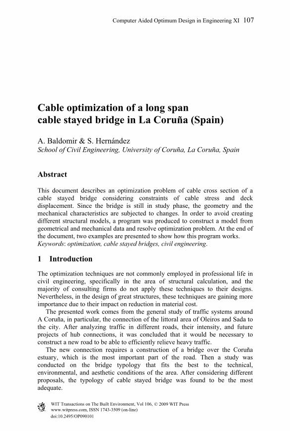
The main elements that compose the bridge are: • Deck: made of steel with an aerodynamic section of 3 m of height and 34
meter of width, which permits a configuration of 3 lanes in each direction. The difference in height between two end points is 15 m.
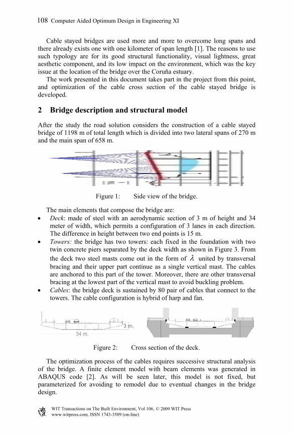
• Towers: the bridge has two towers: each fixed in the foundation with two twin concrete piers separated by the deck width as shown in Figure 3. From the deck two steel masts come out in the form of λ united by transversal bracing and their upper part continue as a single vertical mast. The cables are anchored to this part of the tower. Moreover, there are other transversal bracing at the lowest part of the vertical mast to avoid buckling problem.
• Cables: the bridge deck is sustained by 80 pair of cables that connect to the towers. The cable configuration is hybrid of harp and fan.
Figure 2: Cross section of the deck.
The optimization process of the cables requires successive structural analysis of the bridge. A finite element model with beam elements was generated in ABAQUS code [2]. As will be seen later, this model is not fixed, but parameterized for avoiding to remodel due to eventual changes in the bridge design.
www.witpress.com, ISSN 1743-3509 (on-line) WIT Transactions on The Built Environment, Vol 106, © 2009 WIT Press
108 Computer Aided Optimum Design in Engineering XI
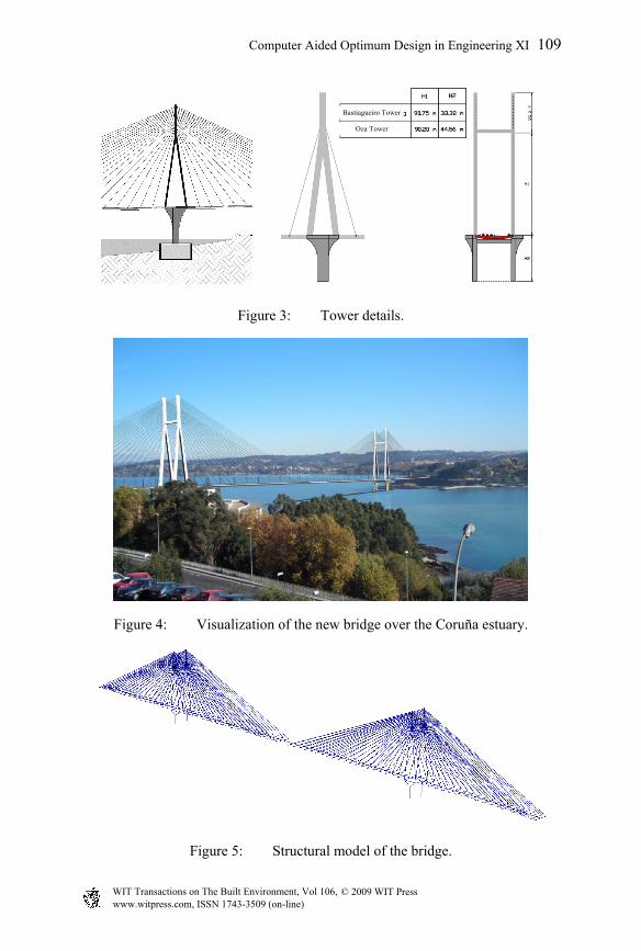
Figure 3: Tower details.
Figure 4: Visualization of the new bridge over the Coruña estuary.
Figure 5: Structural model of the bridge.
Bastiagueiro Tower
Oza Tower
www.witpress.com, ISSN 1743-3509 (on-line) WIT Transactions on The Built Environment, Vol 106, © 2009 WIT Press
Computer Aided Optimum Design in Engineering XI 109
To model the structure, 3D beam element, B31 is used with its rotations released at the beam ends for the cables. The material utilized is steel for the deck and the masts of the towers, and concrete for the lower part of the towers. A linear elastic model is considered with isotropic character for Young’s module and Poisson’s ratio.
3 Formulation of optimization problem
The objective of this work is: to create a program that is able to generate a generic finite element model of a cable stayed bridge (according to the structural scheme proposed in the previous section), to be calculated in ABAQUS, and from the data obtained in this calculation, to perform optimization process on the cable cross sectional area. The optimization problem is defined by the following elements [3–4]: • Design variables The design variables are each of the cable cross sectional areas. The number of design variable is reduced to half of the number of cables due to symmetry about the longitudinal plane; however, it is not symmetrical about the perpendicular plane. For better performance of the optimization process, the inverse of the areas are used to linearize the stress constraints of the cables.
1/i ix A= i = 1,…,n
From now on, we call “n” total number of design variables. • Design constraints Three types of design constraints were taken into account:
1. Stress constraints of the cables
( )ki Mxσ σ≤ i = 1,…,n k=1,…,LC
where:
( )kixσ : normal tensile stress in the cable, “i” for the load case, “k”
Mσ : maximum allowable normal tensile stress in the cables LC : total number of load cases
2. Displacement constraints of the deck
max( )kiw x w≤ i = 2,…,n-1 k=1,…,LC
where:
( )kiw x : deck displacement at the cable position “i” for the load case “k”.
maxw : maximum allowable displacement (positive value)
3. Displacement constraints of towers in the longitudinal direction
www.witpress.com, ISSN 1743-3509 (on-line) WIT Transactions on The Built Environment, Vol 106, © 2009 WIT Press
110 Computer Aided Optimum Design in Engineering XI
maxj
kToweru u≤ j = 1,2 k=1,…,LC
j
kToweru : displacement in “x” direction at the top of the tower “j” for
the load case “k”. maxu : maximum displacement in “x” direction at the top of the tower
(positive value). • Objective function F(X) The objective of optimization in this case is to reduce the quantity of steel for the cables. Thus the objective function is expressed as:
1
1min 2n
ii i
F Lx=
= ⋅ ⋅∑
where: :iL cable length “i” As we can see, this is an optimization problem with “n” design variables, 2n x LC inequality constraints, and an objective function.
4 Program description
The resolution of the problem formulated previously is carried out by a main program created in MATLAB [5] and the use of software ABAQUS for the structural calculation. This program basically consists of three parts:
1. Generation of finite element models. 2. Calculation of initial stresses in the cables for the self weight. 3. Optimization of the cable sections according to the established load
hypotheses.
4.1 Generation of structural model
In this part of the program, we assign dimensions, mechanical characteristics, and discretization for each of the elements that compose the structural model. This part of program consists of three subroutines, “inputtablero”, “inputtorres” and “inputcables” which are in charge of writing Abaqus code according to the data provided initially. Initial values of design variables are assigned to each cable section in the program.
4.2 Initial tension force in the cable
The construction of the bridge is executed by balanced cantilever from each of the towers. The constraint to be satisfied in each phase of the process is the displacement of the deck where cables are attached should be null. Therefore,
www.witpress.com, ISSN 1743-3509 (on-line) WIT Transactions on The Built Environment, Vol 106, © 2009 WIT Press
Computer Aided Optimum Design in Engineering XI 111
just before placing the last center deck section, the bridge should have zero displacement, and after the last deck section is placed, static analysis calculation should show only slight axial forces in such deck section. If the calculation of initial tension with the complete model was carried out, this last deck section would have axial forces above the actual ones. Therefore the calculation of initial tension is carried out on the bridge with its sections without joining and entering the weight of this last deck section.
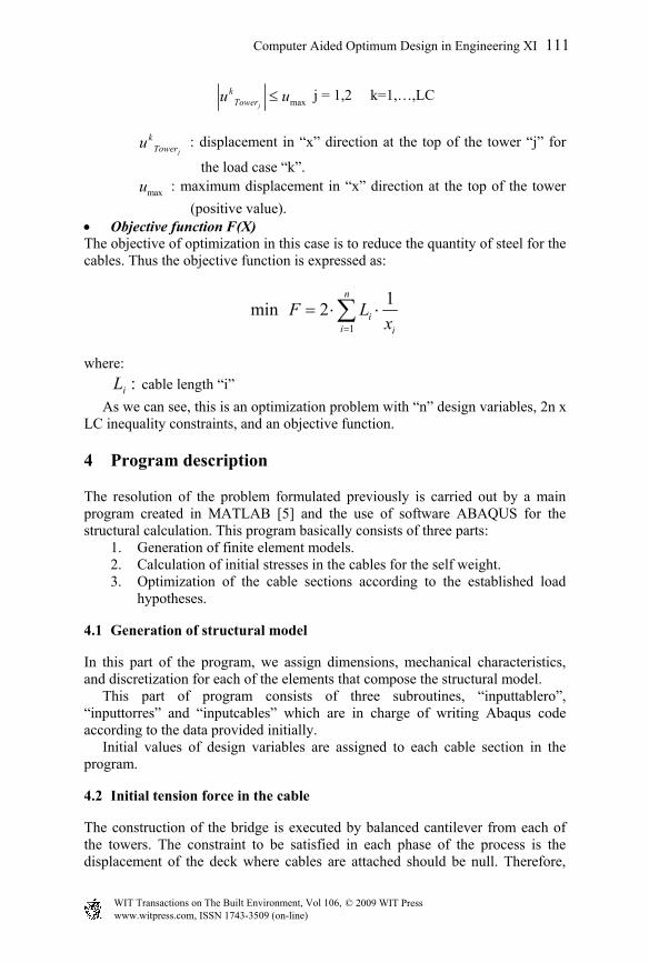
Figure 6: Structural model to obtain the initial tension forces.
These stresses are calculated as follows: 1. Deck displacement is calculated where cables are attached to the deck,
which is produced by self-weight without initial stresses in the cables. 2. A unit force is applied to the first pair of cables and displacement is
obtained at each point of the deck. This operation is repeated for the rest of the cable pairs.
3. Initial tension forces are obtained by resolving the following system of linear equations:
1
0j
npp i
j ii
w P w=
+ ⋅ =∑ j = 1,…,n
pp
jw : deck displacement “j” due to the self-weight load
iP : initial tension force in the cable pair, “i”
j
iw : deck displacement at position, “j” due to the tension force of the
cable pair, “i”
4.3 Optimization
The optimization process is carried out using an optimization module implemented in MATLAB. The function to perform this process is called “fmincon” that minimizes functions with various variables subject to inequality constraints. This optimization subroutine requires certain input values such as design variables, constraints, and an objective function. For obtaining better results, it
www.witpress.com, ISSN 1743-3509 (on-line) WIT Transactions on The Built Environment, Vol 106, © 2009 WIT Press
112 Computer Aided Optimum Design in Engineering XI

also provides gradients of the objective function and the design constraints. Those gradients are calculated by finite difference, the most costly part of the program.
Figure 7: Flow chart of optimization process.
5 Application examples
The first example we present is a fictitious case of a bridge with the same longitudinal profile as the initial bridge described in section 2, but with noticeably reduced number of design variables (n=8). The second example shows the solution obtained for the bridge configuration described at the beginning of the document. The number of variables in this case is much greater than the previous example (n=80). In both examples the optimization of the cable is performed for three simple load cases as:
• Overload of use, 4 KN/m2 on the left lateral span • Overload of use, 4 KN/m2 on the main span • Overload of use, 4 KN/m2 on the right lateral span
www.witpress.com, ISSN 1743-3509 (on-line) WIT Transactions on The Built Environment, Vol 106, © 2009 WIT Press
Computer Aided Optimum Design in Engineering XI 113
Obviously those load cases are not determinant for the limit state defined in the regulation, however, they serve to verify the program performance. The introduction of new load cases in the program does not present any difficulty since these cases simply need to be entered in the subroutine, “casos_carga”.
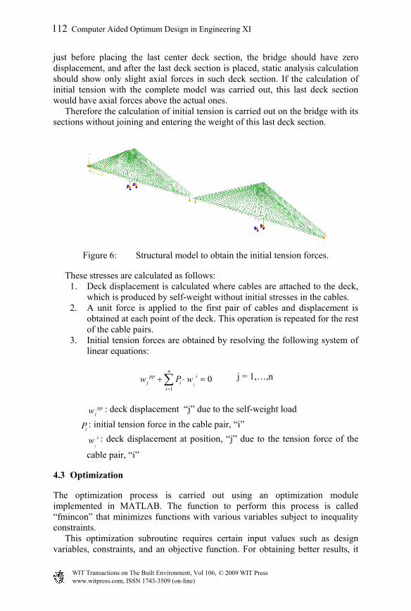
5.1 Bridge with 16 cables
Figure 8: Structural model (16 cables).
• Design variables The design variables are the inverse of the areas of eight cables in the model. We use 0.1m2 for the initial value of the area.
00
1 1 10( ) 0.1ix
A cable i−
= = = i = 1,…,8
• Design constraints The design constraints considered for this example are summarized in the following equations:
2( ) 800000ki
KNxm
σ ≤ i = 1,…,8 k=1,2,3
1( )550
ki
Lw x ≤ i = 2 k=1,2,3; 2( )550
ki
Lw x ≤ i = 3,…,6 k=1,2,3
3( )550
ki
Lw x ≤ i = 7 k=1,2,3; 550j
jkTower
Hu ≤ j =1, 2 k=1,2,3
where L1, L2 and L3 are the length of the left span, main span, and right span respectively and H1 and H2, the tower height. The dimensions are all in meter. • Objective function The objective function is the total volume of steel cables that we intend to minimize.
8
1
12 ii i
F Lx=
= ⋅ ⋅∑
The optimization process converges after 28 iterations giving results shown in figure 10 to 12.
www.witpress.com, ISSN 1743-3509 (on-line) WIT Transactions on The Built Environment, Vol 106, © 2009 WIT Press
114 Computer Aided Optimum Design in Engineering XI
0
0.05
0.1
0.15
0.2
0.25
0.3
0.35
0.4
0.45
0.5
1 6 11 16 21 26
Cable 1Cable2Cable3Cable4Cable5Cable6Cable7Cable8
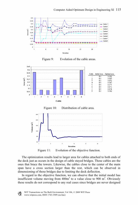
Figure 9: Evolution of the cable areas.
Figure 10: Distribution of cable area.
400
900
1400
1900
2400
2900
1 6 11 16 21 26
Figure 11: Evolution of the objective function.
The optimization results lead to larger area for cables attached to both ends of the deck just as occurs in the design of cable stayed bridges. Those cables are the ones that brace the towers. Likewise, the cables close to the center of the main span have a cross section larger than the rest, which can be observed in dimensioning of those bridges due to limiting the deck deflection. In regard to the objective function, we can observe that the initial model has insufficient volume moving from 400m3 to a value close to 900 m3. Obviously these results do not correspond to any real cases since bridges are never designed
Iteration
Are
a (m
2 )
Iteration
Cable Initial Area Optimal area
Cable
Vol
ume
(m3 )
Are
a (m
2 )
www.witpress.com, ISSN 1743-3509 (on-line) WIT Transactions on The Built Environment, Vol 106, © 2009 WIT Press
Computer Aided Optimum Design in Engineering XI 115
with such small number of cables. We simply want to see the program performance. After the optimization, we checked to see if all the design constraints are satisfied. The displacement constraint in the main span is active for the overload case on this section as well as the stress in the cables adjacent to those with the largest section. None of the constraints are violated.
5.2 Bridge with 160 cables
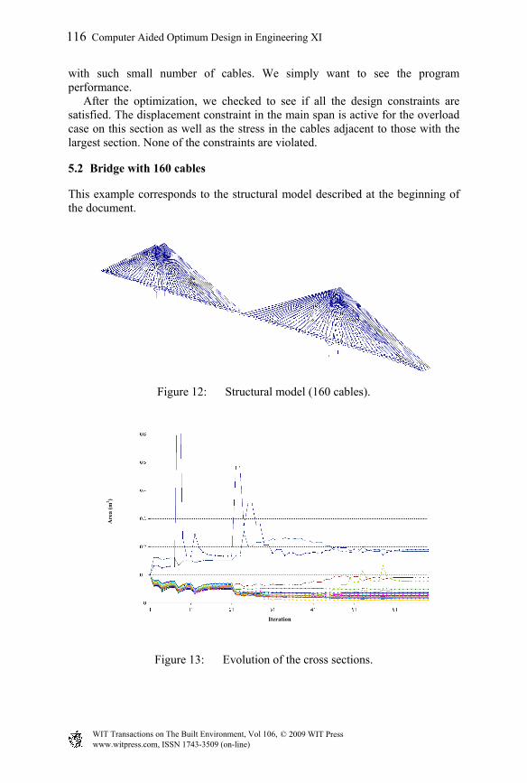
This example corresponds to the structural model described at the beginning of the document.
Figure 12: Structural model (160 cables).
Figure 13: Evolution of the cross sections.
Iteration
Are
a (m
2 )
www.witpress.com, ISSN 1743-3509 (on-line) WIT Transactions on The Built Environment, Vol 106, © 2009 WIT Press
116 Computer Aided Optimum Design in Engineering XI
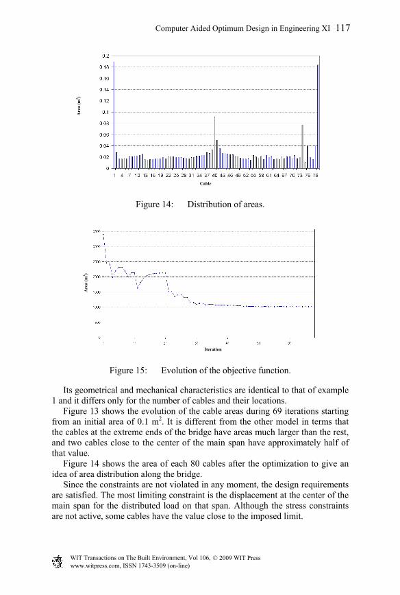
Figure 14: Distribution of areas.
Figure 15: Evolution of the objective function.
Its geometrical and mechanical characteristics are identical to that of example 1 and it differs only for the number of cables and their locations. Figure 13 shows the evolution of the cable areas during 69 iterations starting from an initial area of 0.1 m2. It is different from the other model in terms that the cables at the extreme ends of the bridge have areas much larger than the rest, and two cables close to the center of the main span have approximately half of that value. Figure 14 shows the area of each 80 cables after the optimization to give an idea of area distribution along the bridge. Since the constraints are not violated in any moment, the design requirements are satisfied. The most limiting constraint is the displacement at the center of the main span for the distributed load on that span. Although the stress constraints are not active, some cables have the value close to the imposed limit.
Are
a (m
2 )
Cable
Iteration
Are
a (m
2 )
www.witpress.com, ISSN 1743-3509 (on-line) WIT Transactions on The Built Environment, Vol 106, © 2009 WIT Press
Computer Aided Optimum Design in Engineering XI 117
Obviously we cannot assure that this optimum solution is unique, and there can be other local minimums. Nevertheless, the optimization proves to be useful to give more efficient design than that obtained by heuristic rules.
6 Conclusions
In this work, we have presented the results obtained from a study on the optimization of cable cross section of a cable stayed bridge. Some conclusions can be drawn from the results: 1. Due to high degrees of indeterminacy of this type of structure, the
optimization process is not monotonous presenting discontinuities in the design variables as well as in the objective function. A small modification in the design variables can affect the fulfillment of constraints far away from the location where the changes are produced.
2. We can check the results obtained in the optimization a posteriori by a finite element model. As shown in the examples, we can make sure that the results obtained satisfy the imposed requirements.
3. The program provides an idea to a design engineer how much cross sectional area is necessary for each cable under certain stress and displacement constraints. Since these values are not intuitive a priori at all, they serve as a design tool.
4. The distribution of optimized cable cross section along the bridge agrees with that of actual cable stayed bridges [6].
5. After the optimization process, it can be observed that the areas of cables attached to the extreme ends of the deck are much larger than the rest of the cables. Those cables serve to improve the longitudinal bracing of the towers and at the same time they have an important influence for vertical deck displacements.
6. The cross section of the cables located close to the center of the main span have larger area than the rest other than those at the extreme ends, due to fulfilling the deck displacement constraints.
7. The optimization process provides a result where the objective function has a minimum (local minimum), however, it does not guarantee that it is the best solution among all the possible ones (global maximum). Nevertheless as long as we achieve to reduce the steel volume in comparison to other conventional techniques, the optimization proves to be very useful to reduce material cost.
8. The developed program permits changes on the finite element model (geometry, mechanical properties, boundary condition, etc) in a simple way. Besides it permits to include load hypotheses within the optimization process whenever one is willing to pay the much higher computational cost. This cost is mainly due to obtaining the gradients of design constraints.
The conclusions drawn here on dimensioning of the cables comply exclusively with the terms in which the optimization process is defined. This study can be developed amply from many points of view such as:
www.witpress.com, ISSN 1743-3509 (on-line) WIT Transactions on The Built Environment, Vol 106, © 2009 WIT Press
118 Computer Aided Optimum Design in Engineering XI
1. Including geometry optimization to obtain optimum cable positioning on the deck
2. Including other structural elements such as the deck, towers, etc as design variables.
3. Considering other types of analysis in optimization such as buckling, vibration, dynamic analysis, etc.
4. Possibility of employing other types of optimization algorithms to achieve faster convergence
References
[1] N.J. GIMSING. Cable Supported Bridges. J. Wiley and Sons, Second Edition 1997.
[2] ABAQUS 6.8 Documentation. [3] HERNÁNDEZ, S., Métodos de Diseño Óptimo de Estructuras. [4] JASBIR S. ARORA, Introduction to Optimum Design, Second Edition,
2004. [5] MATLAB Documentation. [6] Honshu-Shikoku Bridge Authority, Japan. The Tatara Bridge. Design and
Construction Technology for the World’s Longest Cable-Stayed Bridge. 1999.
www.witpress.com, ISSN 1743-3509 (on-line) WIT Transactions on The Built Environment, Vol 106, © 2009 WIT Press
Computer Aided Optimum Design in Engineering XI 119


![[TECH]Cable Stayed Bridges](https://img.pdfslide.us/doc/110x75/544cd985b1af9f3a0b8b4c5b/techcable-stayed-bridges.jpg)