Embed Size (px)
Citation preview

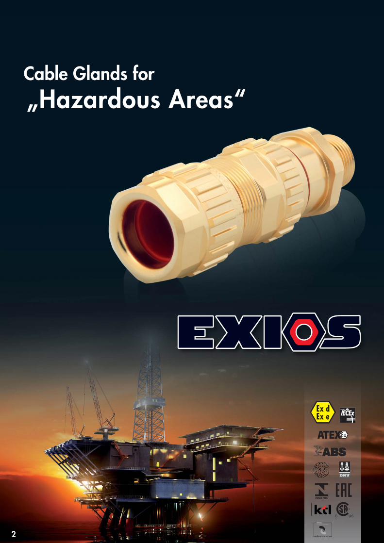
for „Hazardous Areas“Cable Glands
2
Ex dEx e
Registered
Cable Glands for„Hazardous Areas“

Medical device manufacturing combinesthe HUMMEL know-how in many areas. Asa partner of OphthaSWISS AG HUMMELbenefits from modern, patent based measu-rement and calculation methods and worksin close cooperation with renowned scien-tists as well as clinical and technologicalresearch centres.
We deliver certified quality according to theinternational standards DIN ISO 9001 andEN ISO 13485 and produce according tostrict ecological criteria.
HUMMEL is a globally operating, comple-tely independent family-owned businesswith a clear commitment to Germany.Numerous patents, innovations, permanenttechnological advancements, broad rangeof production capacity, flexibility for specialapplications and a clear success strategymake HUMMEL to market leader in its indu-stry.
Through our experience and focus we areable to continuously develop with and par-ticularly for our customers new, innovativesolutions in order to establish new stan-dards.
HUMMEL AG
w w w . h u m m e l . c o m 3
For over 60 years HUMMEL AG has provided outstanding solutions for all forms of cable management applications in theform of cable glands, metal circular connectors and box enclosures. Our NEW innovative EXIOS range of Ex d cableglands now offers the highest quality, reliability, ease of installation and above all safety for all hazardous area applications by meeting the very latest ATEX / IECEx Standards.
HUMMEL AG continues to invest in its ongoing programme ofEx product development to provide its customers with the bestproduct and safety features – We aim to meet our Companymotto:
HUMMEL AG has a worldwide reputation as a leading manu-facturer of electro-mechanical devices and offers the latest construction, tool making, plating, and assembly within our automated factory processes. Our staffs are trained to the highest standards.
EXIOS should be the new choice of specification
Used primarily on Offshore / Onshore Oil & Gas Explorationthe EXIOS is gaining rapid global recognition as the leadingEx Gland for Dual Seal and Barrier applications. Together withthe existing high specification of our premier brand – HSK –HUMMEL can offer cable glands for Exd / Exe / Exi areas in V0rated plastic, brass, nickel plated, stainless steel. Linked to theseitems are our approved range of cable gland accessories.
HUMMEL AG offers its customer base the Global Coverage demanded with point of contact in most continents. See the HUMMEL website for our locations and network of sales agentsand distributors. Quality Management is fundamental to our approach and EXIOS is produced to ISO 9001: 2008 and thevery latest flameproof standards globally.
EXIOS IS THE NUMBER ONE CHOICE FOR ALL Ex d CABLE GLANDS

General:The quality of our products has been certified by many different certification bodies and authorities. HUMMEL AG is a certified manufacturer and supplier of electro-mechanical devices.
Zone 1
Zone 2
Zone 0
Zone 0
4
What is an explosion?
Potentially Explosive Atmosphere
Zones IEC/CENELEC/ATEX
Zones IEC/CENELEC/ATEX Gases and Dust
Temperatur Classes
GA
SD
UST
Temperature Highest permissible Ignition temperature ofclass surface temperature combustible materials
of the operating facility
T1 450 °C > 450 °CT2 300 °C > 300 °C < 450 °CT3 200 °C > 200 °C < 300 °CT4 135 °C > 135 °C < 200 °CT5 100 °C > 100 °C < 200 °CT6 85 °C > 85 °C < 100 °C
Gas Dust
IIA Propane IIIA combustible dustIIB Ethylene IIIB non-conductive dustIIC Hydrogene IIIC conductive dust
Group I Mining
• M1 high degree of safety EPL Ma• M2 high degree of safety EPL Mb
Group II Non-Mining
• 1 very high degree of safety• Gas (Zone 0, 1, 2) EPL Ga• Dust (Zone 20, 21, 22) EPL Da
• 2 high degree of safety • Gas (Zone 1 ,2) EPL Gb• Dust (Zone 21,22) EPL Db
• 3 normal degree of safety• Gas (Zone 2) EPL Gc• Dust (Zone 22) EPL Dc
Zone 0 relates to areas in which a potentially explosive atmosphere consisting of a mixture of air and gases, vapours or mist exists
continuously, for long periods or frequently
Zone 1 relates to areas in which it can be considered that a potentially explosive atmosphere of gases, vapours or mist occurs occasionally
Zone 2 relates to areas in which it is unlikely that a potentially explosive atmosphere of gases, vapours or mist might occur,
but if it does occur then in all probability only seldom and for a short period
Zone 20 relates to areas in which a potentially explosive atmosphere consisting of a mixture of dust and air exists continuously,
for long periods or frequently
Zone 21 relates to areas in which it can be considered that a potentially explosive atmosphere of a mixture of dust and air occurs
occasionally
Zone 22 (note the difference between conductive and non-conductive dust!) relates to areas in which it is unlikely that a potentially explosive
atmosphere of suspended dust might occur, but if it does occur then in all probability only seldom and for a short period
So that an explosion can occur, three conditions must be fulfilled; see the explosion triangle diagramm.1. Fuel2. Oxygen3. Source of ignition
If one removes one of these three conditions, an explosion cannot occur.
A potentially explosive atmosphere is understood to be a mixture of a combustible material and oxygen. Oxygen is generally present as a component ofair. Combustible materials can be e.g.: gases, fluids, vapours, mist or dusts. If the proportion of oxygen falls below a certain value dependent on the mate-rial, known as the oxygen limit concentration, then this mixture cannot be ignited.

IP x3 IP x4
Pene
trat
ion
of w
ater
IP x1IP x0
IP 1x
IP 2x
IP 3x
IP 4x
IP 5x
IP 6x
IP 0x
IP x2 IP x7 IP x8IP x5 IP x6
1. Code
2. C
ode
IP 11
IP 21
IP 31
IP 41
IP 10
IP 20
IP 30
IP 40
IP 50
IP 60
IP 00
IP 12
IP 22
IP 32
IP 42
IP 23
IP 33
IP 43
IP 54
IP 34
IP 44
IP 65
IP 55
IP 66 IP 67 IP 68
R
L C
x
5
Protection Concepts
International Protection, EN 60529
Standards
Electrical
Intrinsic safety Ex ia IEC 60079-11/EN 60079-11 Zone 0,1,2 Limit the energy
Intrinsic safety Ex ib IEC 60079-11/EN 60079-11 Zone 1,2
Intrinsic safety Ex ic IEC 60079-11/EN 60079-11 Zone 2
Increased safety Ex e IEC 60079-7/EN 60079-7 Zone 1,2 No arcs, sparks or
hot surfaces, IP54 or better.
Flameproof enclosure Ex d IEC 60079-1/EN 60079-1 Zone 1,2 Contain the explosion
Use a flamepath.
Dust Protection
Enclosure Ex t IEC 60079-31/EN 60079-31 Zone 20,21,22 Dust tight enclosure IP6X
IEC 60079-0:2011 IEC 60079-1:2014 IEC 60079-7:2006-07 IEC 60079-31:2013EN 60079-0:2012 EN 60079-1:2014 EN 60079-7:2007 EN 60079-31:2014EN 60529
Non
-pro
tect
ed
prot
ectio
n ag
ains
t drip
wat
er (o
r drip
ping
wat
er)
Prot
ecte
d ag
ains
t ve
rtica
lly fa
lling
wat
erdr
ops
whe
n de
vice
is
tilte
d up
to 1
5 °
Wat
er s
pray
ed a
t an
angl
e up
to 6
0 °
on
eith
er s
ide
of th
e ve
rtica
lsh
all h
ave
no h
arm
ful e
ffect
s
Wat
er s
plas
hed
from
any
dire
ctio
n sh
all
have
no
harm
ful e
ffect
s
Wat
er p
roje
cted
in je
tsfro
m a
ny d
irect
ion
shal
lha
ve n
o ha
rmfu
l effe
cts
Wat
er p
roje
cted
inpo
wer
ful j
ets
from
an
y di
rect
ion
shal
l ha
ve n
o ha
rmfu
l effe
cts
prot
ectio
n ag
ains
tte
mpo
rary
sub
mer
sion
prot
ectio
n ag
ains
tpe
rman
ent s
ubm
ersi
on
Protected against solid foreign objects larger indiameter than 50 mm
Protected against solid foreign object larger indiameter than 12,5 mm
Protected against solid foreign objects larger in diameter than 2,5 mm
Protected against solid foreign objects larger indiameter than 1 mm
Prevents penetration of dustsufficient to cause damageinside the equipment.
Dust proof
Non-protected
Protected against access to hazardous parts with the back of the hand
Protected against access to hazardous parts with a finger
Protected against access to hazardous parts with a tool larger in diameter than 25 mm
Protected against access to hazardous parts with a wire larger in diameter than 1,0 mm
Protected against access to hazardous parts with a wire larger in diameter than 1,0 mm
Protected against access to hazardous parts with a wire larger in diameter than 1,0 mm
Non-protected
Protection against human access to hazardous parts
Protection of equipment against penetrationof solid foreign objects
6
–60
°C °C
+ 105
Ex dEx e
Registered
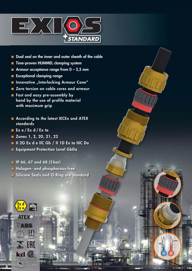
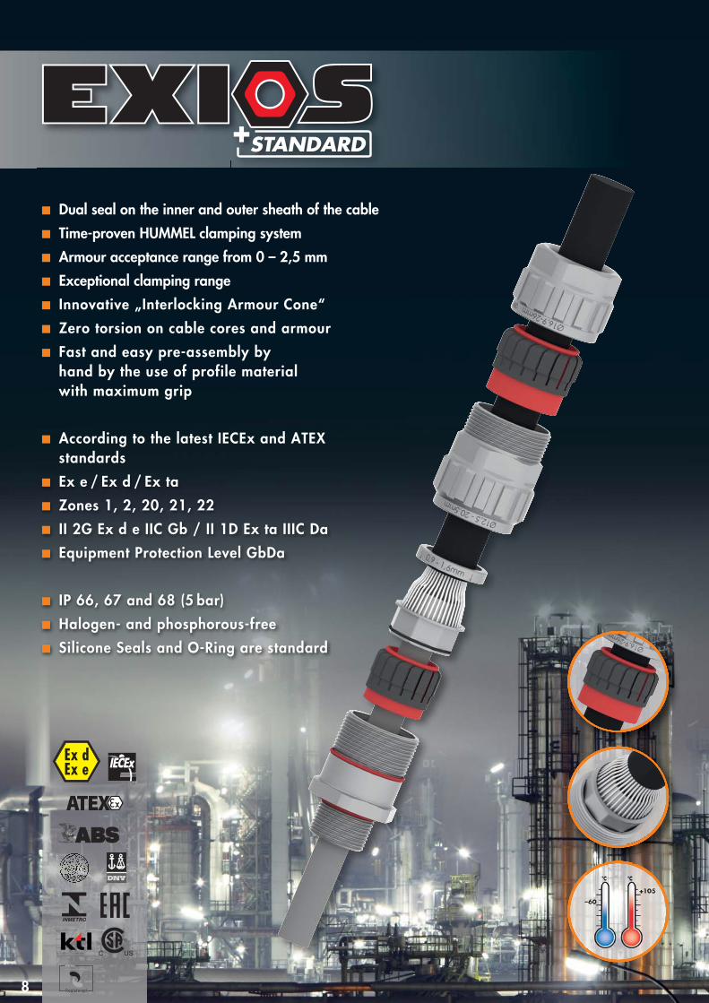
Dual seal on the inner and outer sheath of the cableTime-proven HUMMEL clamping systemArmour acceptance range from 0 – 2,5 mmExceptional clamping range Innovative „Interlocking Armour Cone“Zero torsion on cable cores and armourFast and easy pre-assembly by hand by the use of profile material with maximum grip
According to the latest IECEx and ATEX standardsEx e / Ex d / Ex taZones 1, 2, 20, 21, 22II 2G Ex d e IIC Gb / II 1D Ex ta IIIC DaEquipment Protection Level GbDa
IP 66, 67 and 68 (5 bar)Halogen- and phosphorous-freeSilicone Seals and O-Ring are standard

AG
GL
A1
H
A2 D
7
Type: EXIOS Standard Materials and Technical Data
Material brass, stainless steel on request
Seals / O-Rings silicone, VMQ
Clamping insert PA 6
Armour Metallic Armour or Screen
Temperature Range -60° C – 105° C (-76 °F – 221 °F)
Protection IP 66, 67 and 68 (5 bar)
Certificate IECEx BVS 10.0078 X
BVS 10 ATEX E 062 X
CSA 2557737
Metric brass
Number Gland AG D H GL A1 A2 Clamping Clamping Ring3Size mm mm max. mm mm mm ring 1 ring 2 optional
1.605.1600.50 20 – 1 M 16 x 1,5 22 27 69,5 16 6 – 12 3 – 8,1 0 – 0,7 0,7 – 1,25 –
1.605.2000.50 20 – 1 M 20 x 1,5 22 27 69,5 16 6 – 12 3 – 8,1 0 – 0,7 0,7 – 1,25 –
1.605.2000.51 20 – 2 M 20 x 1,5 24 29 74,3 16 9 – 16 6 – 12 0 – 0,7 0,7 – 1,25 –
1.605.2000.52 20 – 3 M 20 x 1,5 30 35 80,5 16 12,5 – 20,5 9 – 14 0 – 0,7 0,7 – 1,4 –
1.605.2500.51 20 – 3 M 25 x 1,5 30 35 80,5 16 12,5 – 20,5 9 – 14 0 – 0,7 0,7 – 1,4 –
1.605.2500.50 25 M 25 x 1,5 36 42 91 16 16,9 – 26 12,5 – 20,5 0 – 0,7 0,9 – 1,6 0,7 –1,4
1.605.3200.50 32 M 32 x 1,5 46 52 96 16 22 – 33 16,9 – 26 0 – 0,7 1,3 – 2,0 0,7 –1,4
1.605.4000.50 40 M 40 x 1,5 55 64 107 16 28 – 41 22 – 33 0 – 0,7 1,3 – 2,0 0,7 –1,4
1.605.5000.50 50 M 50 x 1,5 65 73 131,5 16 36 – 52,6 28,9 – 44,4 0 – 1,0 1,5 – 2,5 1,0 –2,0
1.605.6300.50 63 M 63 x 1,5 80 90 144,5 16 46 – 65,3 39,9 – 56,3 0 – 1,0 1,5 – 2,5 1,0 –2,0
1.605.7500.50 75 M 75 x 1,5 95 107 154 16 57 – 78 50,5 – 68,2 0 – 1,0 1,5 – 2,5 1,0 –2,0
Armour mm
NPT brass
Number Gland AG D H GL A1 A2 Clamping Clamping Ring3Size mm mm max. mm mm mm ring 1 ring 2 optional
1.605.3800.70 20 – 1 NPT 3/8" 22 27 69,5 16 6 – 12 3 – 8,1 0 – 0,7 0,7 – 1,25 –
1.605.1200.70 20 – 2 NPT 1/2" 24 29 74,3 20 9 – 16 6 – 12 0 – 0,7 0,7 – 1,25 –
1.605.1200.71 20 – 3 NPT 1/2" 30 35 80,5 20 12,5 – 20,5 9 – 14 0 – 0,7 0,7 – 1,4 –
1.605.3400.70 25 NPT 3/4" 36 42 91 20,5 16,9 – 26 12,5 – 20,5 0 – 0,7 0,9 – 1,6 0,7 –1,4
1.605.1000.70 32 NPT 1" 46 52 96 25 22 – 33 16,9 – 26 0 – 0,7 1,3 – 2,0 0,7 –1,4
1.605.5400.70 40 NPT 1 1/4" 55 64 107 26 28 – 41 22 – 33 0 – 0,7 1,3 – 2,0 0,7 –1,4
1.605.6400.70 40 NPT 1 1/2" 55 64 107 26,5 28 – 41 22 – 33 0 – 0,7 1,3 – 2,0 0,7 –1,4
1.605.2000.70 50 NPT 2" 65 73 131,5 27 36 – 52,6 28,9 – 44,4 0 – 1,0 1,5 – 2,5 1,0 –2,0
1.605.5200.70 63 NPT 2 1/2" 80 90 144,5 40 46 – 65,3 39,9 – 56,3 0 – 1,0 1,5 – 2,5 1,0 –2,0
1.605.3000.70 75 NPT 3" 95 107 154 41,5 57 – 78 50,5 – 68,2 0 – 1,0 1,5 – 2,5 1,0 –2,0
Armour mm
8
–60
°C °C
+ 105
Ex dEx e
Registered
Dual seal on the inner and outer sheath of the cableTime-proven HUMMEL clamping systemArmour acceptance range from 0 – 2,5 mmExceptional clamping range Innovative „Interlocking Armour Cone“Zero torsion on cable cores and armourFast and easy pre-assembly by hand by the use of profile material with maximum grip
According to the latest IECEx and ATEX standardsEx e / Ex d / Ex taZones 1, 2, 20, 21, 22II 2G Ex d e IIC Gb / II 1D Ex ta IIIC DaEquipment Protection Level GbDa
IP 66, 67 and 68 (5 bar)Halogen- and phosphorous-freeSilicone Seals and O-Ring are standard

AG
GL
A1
H
A2 D
9
Type: EXIOS Standard Materials and Technical Data
Material nickel-plated brass
Seals / O-Rings silicone, VMQ
Clamping insert PA 6
Armour Metallic Armour or Screen
Temperature Range -60° C – 105° C (-76 °F – 221 °F)
Protection IP 66, 67 and 68 (5 bar)
Certificate IECEx BVS 10.0078 X
BVS 10 ATEX E 062 X
CSA 2557737
Metric nickel plated brass
Number Gland AG D H GL A1 A2 Clamping Clamping Ring3Size mm mm max. mm mm mm ring 1 ring 2 optional
Armour mm
NPT nickel plated brass
Number Gland AG D H GL A1 A2 Clamping Clamping Ring3Size mm mm max. mm mm mm ring 1 ring 2 optional
Armour mm
1.605.1603.50 20 – 1 M 16 x 1,5 22 27 69,5 16 6 – 12 3 – 8,1 0 – 0,7 0,7 – 1,25 –
1.605.2003.50 20 – 1 M 20 x 1,5 22 27 69,5 16 6 – 12 3 – 8,1 0 – 0,7 0,7 – 1,25 –
1.605.2003.51 20 – 2 M 20 x 1,5 24 29 74,3 16 9 – 16 6 – 12 0 – 0,7 0,7 – 1,25 –
1.605.2003.52 20 – 3 M 20 x 1,5 30 35 80,5 16 12,5 – 20,5 9 – 14 0 – 0,7 0,7 – 1,4 –
1.605.2503.51 20 – 3 M 25 x 1,5 30 35 80,5 16 12,5 – 20,5 9 – 14 0 – 0,7 0,7 – 1,4 –
1.605.2503.50 25 M 25 x 1,5 36 42 91 16 16,9 – 26 12,5 – 20,5 0 – 0,7 0,9 – 1,6 0,7 –1,4
1.605.3203.50 32 M 32 x 1,5 46 52 96 16 22 – 33 16,9 – 26 0 – 0,7 1,3 – 2,0 0,7 –1,4
1.605.4003.50 40 M 40 x 1,5 55 64 107 16 28 – 41 22 – 33 0 – 0,7 1,3 – 2,0 0,7 –1,4
1.605.5003.50 50 M 50 x 1,5 65 73 131,5 16 36 – 52,6 28,9 – 44,4 0 – 1,0 1,5 – 2,5 1,0 –2,0
1.605.6303.50 63 M 63 x 1,5 80 90 144,5 16 46 – 65,3 39,9 – 56,3 0 – 1,0 1,5 – 2,5 1,0 –2,0
1.605.7503.50 75 M 75 x 1,5 95 107 154 16 57 – 78 50,5 – 68,2 0 – 1,0 1,5 – 2,5 1,0 –2,0
1.605.3803.70 20 – 1 NPT 3/8" 22 27 69,5 16 6 – 12 3 – 8,1 0 – 0,7 0,7 – 1,25 –
1.605.1203.70 20 – 2 NPT 1/2" 24 29 74,3 20 9 – 16 6 – 12 0 – 0,7 0,7 – 1,25 –
1.605.1203.71 20 – 3 NPT 1/2" 30 35 80,5 20 12,5 – 20,5 9 – 14 0 – 0,7 0,7 – 1,4 –
1.605.3403.70 25 NPT 3/4" 36 42 91 20,5 16,9 – 26 12,5 – 20,5 0 – 0,7 0,9 – 1,6 0,7 –1,4
1.605.1003.70 32 NPT 1" 46 52 96 25 22 – 33 16,9 – 26 0 – 0,7 1,3 – 2,0 0,7 –1,4
1.605.5403.70 40 NPT 1 1/4" 55 64 107 26 28 – 41 22 – 33 0 – 0,7 1,3 – 2,0 0,7 –1,4
1.605.6403.70 40 NPT 1 1/2" 55 64 107 26,5 28 – 41 22 – 33 0 – 0,7 1,3 – 2,0 0,7 –1,4
1.605.2003.70 50 NPT 2" 65 73 131,5 27 36 – 52,6 28,9 – 44,4 0 – 1,0 1,5 – 2,5 1,0 –2,0
1.605.5203.70 63 NPT 2 1/2" 80 90 144,5 40 46 – 65,3 39,9 – 56,3 0 – 1,0 1,5 – 2,5 1,0 –2,0
1.605.3003.70 75 NPT 3" 95 107 154 41,5 57 – 78 50,5 – 68,2 0 – 1,0 1,5 – 2,5 1,0 –2,0
10
–60
°C °C
+ 85
Ex dEx e
Registered
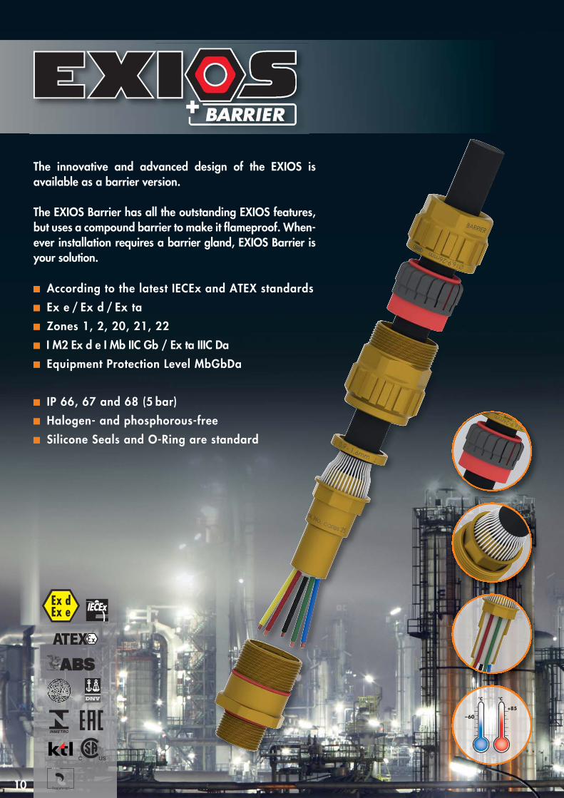
The innovative and advanced design of the EXIOS is available as a barrier version.
The EXIOS Barrier has all the outstanding EXIOS features,but uses a compound barrier to make it flameproof. When-ever installation requires a barrier gland, EXIOS Barrier isyour solution.
According to the latest IECEx and ATEX standardsEx e / Ex d / Ex taZones 1, 2, 20, 21, 22I M2 Ex d e I Mb IIC Gb / Ex ta IIIC DaEquipment Protection Level MbGbDa
IP 66, 67 and 68 (5 bar)Halogen- and phosphorous-freeSilicone Seals and O-Ring are standard

A2
A3
AG
GL H
D
A1
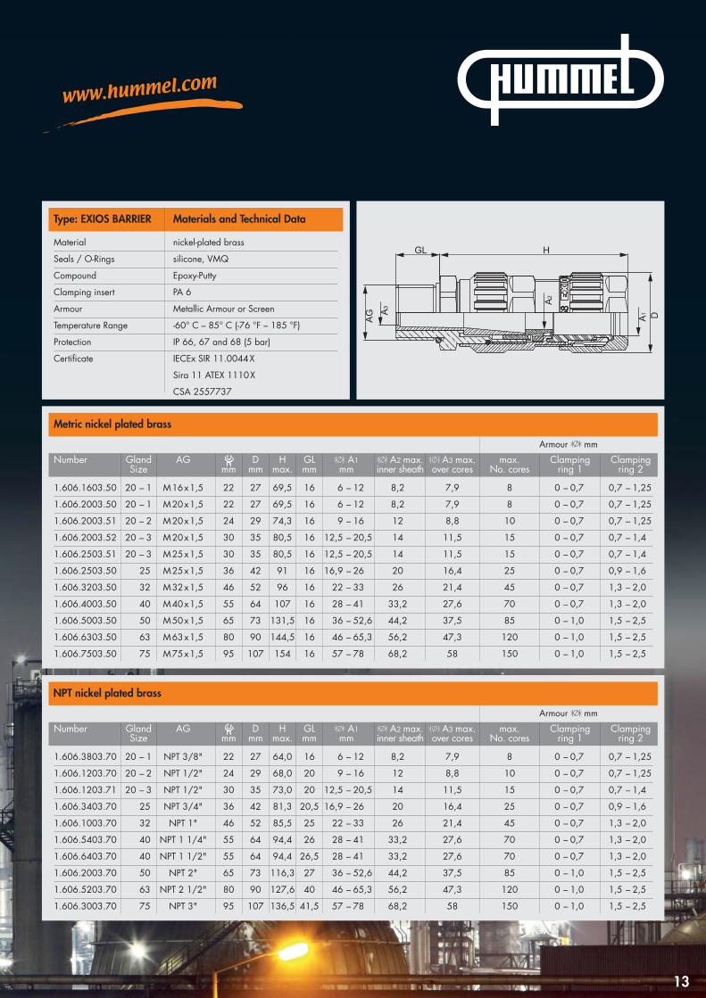
Type: EXIOS BARRIER Materials and Technical Data
Material brass, stainless steel on request
Seals / O-Rings silicone, VMQ
Compound Epoxy-Putty
Clamping insert PA 6
Armour Metallic Armour or Screen
Temperature Range -60° C – 85° C (-76 °F – 185 °F)
Protection IP 66, 67 and 68 (5 bar)
Certificate IECEx SIR 11.0044 X
Sira 11 ATEX 1110 X
CSA 2557737
Metric brass
Number Gland AG D H GL A1 A2 max. A3 max. max. Clamping ClampingSize mm mm max. mm mm inner sheath over cores No. cores ring 1 ring 2
Armour mm
NPT brass
1.606.3800.70 20 – 1 NPT 3/8" 22 27 64,0 16 6 – 12 8,2 7,9 8 0 – 0,7 0,7 – 1,25
1.606.1200.70 20 – 2 NPT 1/2" 24 29 68,0 20 9 – 16 12 8,8 10 0 – 0,7 0,7 – 1,25
1.606.1200.71 20 – 3 NPT 1/2" 30 35 73,0 20 12,5 – 20,5 14 11,5 15 0 – 0,7 0,7 – 1,4
1.606.3400.70 25 NPT 3/4" 36 42 81,3 20,5 16,9 – 26 20 16,4 25 0 – 0,7 0,9 – 1,6
1.606.1000.70 32 NPT 1" 46 52 85,5 25 22 – 33 26 21,4 45 0 – 0,7 1,3 – 2,0
1.606.5400.70 40 NPT 1 1/4" 55 64 94,4 26 28 – 41 33,2 27,6 70 0 – 0,7 1,3 – 2,0
1.606.6400.70 40 NPT 1 1/2" 55 64 94,4 26,5 28 – 41 33,2 27,6 70 0 – 0,7 1,3 – 2,0
1.606.2000.70 50 NPT 2" 65 73 116,3 27 36 – 52,6 44,2 37,5 85 0 – 1,0 1,5 – 2,5
1.606.5200.70 63 NPT 2 1/2" 80 90 127,6 40 46 – 65,3 56,2 47,3 120 0 – 1,0 1,5 – 2,5
1.606.3000.70 75 NPT 3" 95 107 136,5 41,5 57 – 78 68,2 58 150 0 – 1,0 1,5 – 2,5
Armour mm
1.606.1600.50 20 – 1 M 16 x 1,5 22 27 69,5 16 6 – 12 8,2 7,9 8 0 – 0,7 0,7 – 1,25
1.606.2000.50 20 – 1 M 20 x 1,5 22 27 69,5 16 6 – 12 8,2 7,9 8 0 – 0,7 0,7 – 1,25
1.606.2000.51 20 – 2 M 20 x 1,5 24 29 74,3 16 9 – 16 12 8,8 10 0 – 0,7 0,7 – 1,25
1.606.2000.52 20 – 3 M 20 x 1,5 30 35 80,5 16 12,5 – 20,5 14 11,5 15 0 – 0,7 0,7 – 1,4
1.606.2500.51 20 – 3 M 25 x 1,5 30 35 80,5 16 12,5 – 20,5 14 11,5 15 0 – 0,7 0,7 – 1,4
1.606.2500.50 25 M 25 x 1,5 36 42 91 16 16,9 – 26 20 16,4 25 0 – 0,7 0,9 – 1,6
1.606.3200.50 32 M 32 x 1,5 46 52 96 16 22 – 33 26 21,4 45 0 – 0,7 1,3 – 2,0
1.606.4000.50 40 M 40 x 1,5 55 64 107 16 28 – 41 33,2 27,6 70 0 – 0,7 1,3 – 2,0
1.606.5000.50 50 M 50 x 1,5 65 73 131,5 16 36 – 52,6 44,2 37,5 85 0 – 1,0 1,5 – 2,5
1.606.6300.50 63 M 63 x 1,5 80 90 144,5 16 46 – 65,3 56,2 47,3 120 0 – 1,0 1,5 – 2,5
1.606.7500.50 75 M 75 x 1,5 95 107 154 16 57 – 78 68,2 58 150 0 – 1,0 1,5 – 2,5
Number Gland AG D H GL A1 A2 max. A3 max. max. Clamping ClampingSize mm mm max. mm mm inner sheath over cores No. cores ring 1 ring 2
11

12
–60
°C °C
+ 85
Ex dEx e
Registered
The innovative and advanced design of the EXIOS is available as a barrier version.
The EXIOS Barrier has all the outstanding EXIOS features,but uses a compound barrier to make it flameproof. When-ever installation requires a barrier gland, EXIOS Barrier isyour solution.
According to the latest IECEx and ATEX standardsEx e / Ex d / Ex taZones 1, 2, 20, 21, 22I M2 Ex d e I Mb IIC Gb / Ex ta IIIC DaEquipment Protection Level MbGbDa
IP 66, 67 and 68 (5 bar)Halogen- and phosphorous-freeSilicone Seals and O-Ring are standard
A2
A3
AG
GL H
D
A1
Type: EXIOS BARRIER Materials and Technical Data
Material nickel-plated brass
Seals / O-Rings silicone, VMQ
Compound Epoxy-Putty
Clamping insert PA 6
Armour Metallic Armour or Screen
Temperature Range -60° C – 85° C (-76 °F – 185 °F)
Protection IP 66, 67 and 68 (5 bar)
Certificate IECEx SIR 11.0044 X
Sira 11 ATEX 1110 X
CSA 2557737
Metric nickel plated brass
Number Gland AG D H GL A1 A2 max. A3 max. max. Clamping ClampingSize mm mm max. mm mm inner sheath over cores No. cores ring 1 ring 2
Armour mm
NPT nickel plated brass
Armour mm
Number Gland AG D H GL A1 A2 max. A3 max. max. Clamping ClampingSize mm mm max. mm mm inner sheath over cores No. cores ring 1 ring 2
13
1.606.3803.70 20 – 1 NPT 3/8" 22 27 64,0 16 6 – 12 8,2 7,9 8 0 – 0,7 0,7 – 1,25
1.606.1203.70 20 – 2 NPT 1/2" 24 29 68,0 20 9 – 16 12 8,8 10 0 – 0,7 0,7 – 1,25
1.606.1203.71 20 – 3 NPT 1/2" 30 35 73,0 20 12,5 – 20,5 14 11,5 15 0 – 0,7 0,7 – 1,4
1.606.3403.70 25 NPT 3/4" 36 42 81,3 20,5 16,9 – 26 20 16,4 25 0 – 0,7 0,9 – 1,6
1.606.1003.70 32 NPT 1" 46 52 85,5 25 22 – 33 26 21,4 45 0 – 0,7 1,3 – 2,0
1.606.5403.70 40 NPT 1 1/4" 55 64 94,4 26 28 – 41 33,2 27,6 70 0 – 0,7 1,3 – 2,0
1.606.6403.70 40 NPT 1 1/2" 55 64 94,4 26,5 28 – 41 33,2 27,6 70 0 – 0,7 1,3 – 2,0
1.606.2003.70 50 NPT 2" 65 73 116,3 27 36 – 52,6 44,2 37,5 85 0 – 1,0 1,5 – 2,5
1.606.5203.70 63 NPT 2 1/2" 80 90 127,6 40 46 – 65,3 56,2 47,3 120 0 – 1,0 1,5 – 2,5
1.606.3003.70 75 NPT 3" 95 107 136,5 41,5 57 – 78 68,2 58 150 0 – 1,0 1,5 – 2,5
1.606.1603.50 20 – 1 M 16 x 1,5 22 27 69,5 16 6 – 12 8,2 7,9 8 0 – 0,7 0,7 – 1,25
1.606.2003.50 20 – 1 M 20 x 1,5 22 27 69,5 16 6 – 12 8,2 7,9 8 0 – 0,7 0,7 – 1,25
1.606.2003.51 20 – 2 M 20 x 1,5 24 29 74,3 16 9 – 16 12 8,8 10 0 – 0,7 0,7 – 1,25
1.606.2003.52 20 – 3 M 20 x 1,5 30 35 80,5 16 12,5 – 20,5 14 11,5 15 0 – 0,7 0,7 – 1,4
1.606.2503.51 20 – 3 M 25 x 1,5 30 35 80,5 16 12,5 – 20,5 14 11,5 15 0 – 0,7 0,7 – 1,4
1.606.2503.50 25 M 25 x 1,5 36 42 91 16 16,9 – 26 20 16,4 25 0 – 0,7 0,9 – 1,6
1.606.3203.50 32 M 32 x 1,5 46 52 96 16 22 – 33 26 21,4 45 0 – 0,7 1,3 – 2,0
1.606.4003.50 40 M 40 x 1,5 55 64 107 16 28 – 41 33,2 27,6 70 0 – 0,7 1,3 – 2,0
1.606.5003.50 50 M 50 x 1,5 65 73 131,5 16 36 – 52,6 44,2 37,5 85 0 – 1,0 1,5 – 2,5
1.606.6303.50 63 M 63 x 1,5 80 90 144,5 16 46 – 65,3 56,2 47,3 120 0 – 1,0 1,5 – 2,5
1.606.7503.50 75 M 75 x 1,5 95 107 154 16 57 – 78 68,2 58 150 0 – 1,0 1,5 – 2,5

–60
°C °C
+ 105
14
Ex dEx e
Registered
With the EXIOS A2F, HUMMEL follows the successfuldesign of the EXIOS range of cable glands. This modelis especially designed for unarmoured and braidedcables where durability and quality is a must.
The EXIOS A2F incorporates the time-proven HUMMELclamping system, which offers a large clamping rangein a small gland size. Therefore a smaller gland size canoften be used.
According to the latest IECEx and ATEX standardsEx e / Ex d / Ex taZones 1, 2, 20, 21, 22II 2G Ex d e IIC Gb / II 1D Ex ta IIIC DaEquipment Protection Level GbDa
IP 66, 67 and 68 (5 bar)Halogen- and phosphorous-freeSilicone Seals and O-Ring are standard

1515
GL H
AG
A1 D
Type: EXIOS A2F Materials and Technical Data
Material brass, stainless steel on request
Seals / O-Rings silicone, VMQ
Clamping insert PA 6
Temperature Range -60° C – 105° C (-76 °F – 221 °F)
Protection IP 66, 67 and 68 (5 bar)
Certificate IECEx DEK 12.0039 X
DEKRA 12 ATEX 0139 X
CSA 2557737
Metric brass
Number Gland AG D H GL A1Size mm mm max. mm mm
NPT brass
1.608.1600.50 20 – 1 M 16 x 1,5 22 27 35,6 16 6 – 12
1.608.2000.50 20 – 1 M 20 x 1,5 22 27 35,6 16 6 – 12
1.608.2000.51 20 – 2 M 20 x 1,5 24 29 39,7 16 9 – 16
1.608.2500.50 20 – 3 M 25x 1,5 30 35 47,5 16 12,5 – 20,5
1.608.3200.50 25 M 32 x 1,5 36 42 47,8 16 16,9 – 26
1.608.4000.50 32 M 40 x 1,5 46 52 51,1 16 22 – 33
1.608.5000.50 40 M 50 x 1,5 55 64 56,8 16 28 – 41
1.608.6300.50 50 M 63 x 1,5 65 73 65,4 16 40 – 52,6
1.608.7500.50 63 M 75 x 1,5 80 90 70,3 16 51 – 65,3
1.608.9000.50 75 M 90 x 2,0 95 107 76,2 20 62 – 78
Number Gland AG D H GL A1Size mm mm max. mm mm
1.608.3800.70 20 – 1 NPT 3/8" 22 27 35,6 16 6 – 12
1.608.1200.70 20 – 1 NPT 1/2" 22 / 24 27 35,6 20 6 – 12
1.608.1200.71 20 – 2 NPT 1/2" 24 29 39,7 20 9 – 16
1.608.3400.70 20 – 3 NPT 3/4" 30 35 47,5 20,5 12,5 – 20,5
1.608.1000.70 25 NPT 1" 36 42 47,8 25 16,9 – 26
1.608.5400.70 32 NPT 1 1/4" 46 52 51,1 26 22 – 33
1.608.6400.70 40 NPT 1 1/2" 55 64 56,8 26,5 28 – 41
1.608.2000.70 50 NPT 2" 65 73 65,4 27 40 – 52,6
1.608.5200.70 63 NPT 2 1/2" 80 90 70,3 40 51 – 61
1.608.3000.70 75 NPT 3" 95 107 76,2 41,5 62 – 78

161616
–60
°C °C
+ 105
With the EXIOS A2F, HUMMEL follows the successfuldesign of the EXIOS range of cable glands. This modelis especially designed for unarmoured and braidedcables where durability and quality is a must.
The EXIOS A2F incorporates the time-proven HUMMELclamping system, which offers a large clamping rangein a small gland size. Therefore a smaller gland size canoften be used.
According to the latest IECEx and ATEX standardsEx e / Ex d / Ex taZones 1, 2, 20, 21, 22II 2G Ex d e IIC Gb / II 1D Ex ta IIIC DaEquipment Protection Level GbDa
IP 66, 67 and 68 (5 bar)Halogen- and phosphorous-freeSilicone Seals and O-Ring are standard
Ex dEx e
Registered
17171717
Metric nickel plated brass
Number Gland AG D H GL A1Size mm mm max. mm mm
NPT nickel plated brass
Number Gland AG D H GL A1Size mm mm max. mm mm
Type: EXIOS A2F Materials and Technical DataGL H
AG
A1 D
1.608.1603.50 20 – 1 M 16 x 1,5 22 27 35,6 16 6 – 12
1.608.2003.50 20 – 1 M 20 x 1,5 22 27 35,6 16 6 – 12
1.608.2003.51 20 – 2 M 20 x 1,5 24 29 39,7 16 9 – 16
1.608.2503.50 20 – 3 M 25x 1,5 30 35 47,5 16 12,5 – 20,5
1.608.3203.50 25 M 32 x 1,5 36 42 47,8 16 16,9 – 26
1.608.4003.50 32 M 40 x 1,5 46 52 51,1 16 22 – 33
1.608.5003.50 40 M 50 x 1,5 55 64 56,8 16 28 – 41
1.608.6303.50 50 M 63 x 1,5 65 73 65,4 16 40 – 52,6
1.608.7503.50 63 M 75 x 1,5 80 90 70,3 16 51 – 65,3
1.608.9003.50 75 M 90 x 2,0 95 107 76,2 20 62 – 78
1.608.3803.70 20 – 1 NPT 3/8" 22 27 35,6 16 6 – 12
1.608.1203.70 20 – 1 NPT 1/2" 22 / 24 27 35,6 20 6 – 12
1.608.1203.71 20 – 2 NPT 1/2" 24 29 39,7 20 9 – 16
1.608.3403.70 20 – 3 NPT 3/4" 30 35 47,5 20,5 12,5 – 20,5
1.608.1003.70 25 NPT 1" 36 42 47,8 25 16,9 – 26
1.608.5403.70 32 NPT 1 1/4" 46 52 51,1 26 22 – 33
1.608.6403.70 40 NPT 1 1/2" 55 64 56,8 26,5 28 – 41
1.608.2003.70 50 NPT 2" 65 73 65,4 27 40 – 52,6
1.608.5203.70 63 NPT 2 1/2" 80 90 70,3 40 51 – 61
1.608.3003.70 75 NPT 3" 95 107 76,2 41,5 62 – 78
Material nickel-plated brass
Seals / O-Rings silicone, VMQ
Clamping insert PA 6
Temperature Range -60° C – 105° C (-76 °F – 221 °F)
Protection IP 66, 67 and 68 (5 bar)
Certificate IECEx DEK 12.0039 X
DEKRA 12 ATEX 0139 X
CSA 2557737

18
–60
°C °C
+ 105Ex dEx e
Dual seal on the inner and outer sheath of the cableTime-proven HUMMEL clamping systemArmour acceptance range from 0 – 2,5 mmExceptional clamping range Innovative „Interlocking Armour Cone“Zero torsion on cable cores and armourFast and easy pre-assembly by hand by the use of profile material with maximum gripWith additional cable clamp (MZ)
According to the latest IECEx and ATEX standardsEx e / Ex d / Ex taZones 1, 2, 20, 21, 22II 2G Ex d e IIC Gb / II 1D Ex ta IIIC DaEquipment Protection Level GbDa
IP 66, 67 and 68 (5 bar)Halogen- and phosphorous-freeSilicone Seals and O-Ring are standard

19
AG
A2
GL H
A1
D
Type: EXIOS MZ Materials and Technical Data
Material brass, stainless steel on request
Seals / O-Rings silicone, VMQ
Clamping insert PA 6
Armour Metallic Armour or Screen
Temperature Range -60° C – 105° C (-76 °F – 221 °F)
Protection IP 66, 67 and 68 (5 bar)
Certificate IECEx BVS 10.0078 X
BVS 10 ATEX E 062 X
Metric brass
Number Gland AG D H GL A1 A2 Clamping Clamping Ring3Size mm mm max. mm mm mm ring 1 ring 2 optional
Armour mm
NPT brass
Number Gland AG D H GL A1 A2 Clamping Clamping Ring3Size mm mm max. mm mm mm ring 1 ring 2 optional
Armour mm
1.6Z5.1600.50 20 – 1 M 16 x 1,5 22 27 79 16 6 – 11 3 – 8,1 0 – 0,7 0,7 – 1,25 –
1.6Z5.2000.50 20 – 1 M 20 x 1,5 22 27 79 16 6 – 11 3 – 8,1 0 – 0,7 0,7 – 1,25 –
1.6Z5.2000.51 20 – 2 M 20 x 1,5 24 29 83,8 16 9 – 13 6 – 12 0 – 0,7 0,7 – 1,25 –
1.6Z5.2000.52 20 – 3 M 20 x 1,5 30 35 91,5 16 12,5 – 17,5 9 – 14 0 – 0,7 0,7 – 1,4 –
1.6Z5.2500.51 20 – 3 M 25 x 1,5 30 35 91,5 16 12,5 – 17,5 9 – 14 0 – 0,7 0,7 – 1,4 –
1.6Z5.2500.50 25 M 25 x 1,5 36 42 105,7 16 16,9 – 24 12,5 – 20,5 0 – 0,7 0,9 – 1,6 0,7 –1,4
1.6Z5.3200.50 32 M 32 x 1,5 46 52 107 16 22 – 32,5 16,9 – 26 0 – 0,7 1,3 – 2,0 0,7 –1,4
1.6Z5.4000.50 40 M 40 x 1,5 55 64 120 16 28 – 39,5 22 – 33 0 – 0,7 1,3 – 2,0 0,7 –1,4
1.6Z5.5000.50 50 M 50 x 1,5 65 73 144,5 16 36 – 49 28,9 – 44,4 0 – 1,0 1,5 – 2,5 1,0 –2,0
1.6Z5.6300.50 63 M 63 x 1,5 80 90 157,5 16 46 – 64 39,9 – 56,3 0 – 1,0 1,5 – 2,5 1,0 –2,0
1.6Z5.7500.50 75 M 75 x 1,5 95 107 167 16 57 – 78 50,5 – 68,2 0 – 1,0 1,5 – 2,5 1,0 –2,0
1.6Z5.3800.70 20 – 1 NPT 3/8" 22 27 79 16 6 – 11 3 – 8,1 0 – 0,7 0,7 – 1,25 –
1.6Z5.1200.70 20 – 2 NPT 1/2" 24 29 83,8 20 9 – 13 6 – 12 0 – 0,7 0,7 – 1,25 –
1.6Z5.1200.71 20 – 3 NPT 1/2" 30 35 91,5 20 12,5 – 17,5 9 – 14 0 – 0,7 0,7 – 1,4 –
1.6Z5.3400.70 25 NPT 3/4" 36 42 105,7 20,5 16,9 – 24 12,5 – 20,5 0 – 0,7 0,9 – 1,6 0,7 –1,4
1.6Z5.1000.70 32 NPT 1" 46 52 107 25 22 – 32,5 16,9 – 26 0 – 0,7 1,3 – 2,0 0,7 –1,4
1.6Z5.5400.70 40 NPT 1 1/4" 55 64 120 26 28 – 39,5 22 – 33 0 – 0,7 1,3 – 2,0 0,7 –1,4
1.6Z5.6400.70 40 NPT 1 1/2" 55 64 120 26,5 28 – 39,5 22 – 33 0 – 0,7 1,3 – 2,0 0,7 –1,4
1.6Z5.2000.70 50 NPT 2" 65 73 144,5 27 36 – 49 28,9 – 44,4 0 – 1,0 1,5 – 2,5 1,0 –2,0
1.6Z5.5200.70 63 NPT 2 1/2" 80 90 157,5 40 46 – 64 39,9 – 56,3 0 – 1,0 1,5 – 2,5 1,0 –2,0
1.6Z5.3000.70 75 NPT 3" 95 107 167 41,5 57 – 78 50,5 – 68,2 0 – 1,0 1,5 – 2,5 1,0 –2,0

20
–60
°C °C
+ 105Ex dEx e
Dual seal on the inner and outer sheath of the cableTime-proven HUMMEL clamping systemArmour acceptance range from 0 – 2,5 mmExceptional clamping range Innovative „Interlocking Armour Cone“Zero torsion on cable cores and armourFast and easy pre-assembly by hand by the use of profile material with maximum gripWith additional cable clamp (MZ)
According to the latest IECEx and ATEX standardsEx e / Ex d / Ex taZones 1, 2, 20, 21, 22II 2G Ex d e IIC Gb / II 1D Ex ta IIIC DaEquipment Protection Level GbDa
IP 66, 67 and 68 (5 bar)Halogen- and phosphorous-freeSilicone Seals and O-Ring are standard

21
Metric nickel plated brass
Number Gland AG D H GL A1 A2 Clamping Clamping Ring3Size mm mm max. mm mm mm ring 1 ring 2 optional
Armour mm
NPT nickel plated brass
Number Gland AG D H GL A1 A2 Clamping Clamping Ring3Size mm mm max. mm mm mm ring 1 ring 2 optional
Armour mm
AG
A2
GL H
A1
D
Type: EXIOS MZ Materials and Technical Data
Material nickel-plated brass
Seals / O-Rings silicone, VMQ
Clamping insert PA 6
Armour Metallic Armour or Screen
Temperature Range -60° C – 105° C (-76 °F – 221 °F)
Protection IP 66, 67 and 68 (5 bar)
Certificate IECEx BVS 10.0078 X
BVS 10 ATEX E 062 X
1.6Z5.1603.50 20 – 1 M 16 x 1,5 22 27 79 16 6 – 11 3 – 8,1 0 – 0,7 0,7 – 1,25 –
1.6Z5.2003.50 20 – 1 M 20 x 1,5 22 27 79 16 6 – 11 3 – 8,1 0 – 0,7 0,7 – 1,25 –
1.6Z5.2003.51 20 – 2 M 20 x 1,5 24 29 83,8 16 9 – 13 6 – 12 0 – 0,7 0,7 – 1,25 –
1.6Z5.2003.52 20 – 3 M 20 x 1,5 30 35 91,5 16 12,5 – 17,5 9 – 14 0 – 0,7 0,7 – 1,4 –
1.6Z5.2503.51 20 – 3 M 25 x 1,5 30 35 91,5 16 12,5 – 17,5 9 – 14 0 – 0,7 0,7 – 1,4 –
1.6Z5.2503.50 25 M 25 x 1,5 36 42 105,7 16 16,9 – 24 12,5 – 20,5 0 – 0,7 0,9 – 1,6 0,7 –1,4
1.6Z5.3203.50 32 M 32 x 1,5 46 52 107 16 22 – 32,5 16,9 – 26 0 – 0,7 1,3 – 2,0 0,7 –1,4
1.6Z5.4003.50 40 M 40 x 1,5 55 64 120 16 28 – 39,5 22 – 33 0 – 0,7 1,3 – 2,0 0,7 –1,4
1.6Z5.5003.50 50 M 50 x 1,5 65 73 144,5 16 36 – 49 28,9 – 44,4 0 – 1,0 1,5 – 2,5 1,0 –2,0
1.6Z5.6303.50 63 M 63 x 1,5 80 90 157,5 16 46 – 64 39,9 – 56,3 0 – 1,0 1,5 – 2,5 1,0 –2,0
1.6Z5.7503.50 75 M 75 x 1,5 95 107 167 16 57 – 78 50,5 – 68,2 0 – 1,0 1,5 – 2,5 1,0 –2,0
1.6Z5.3803.70 20 – 1 NPT 3/8" 22 27 79 16 6 – 11 3 – 8,1 0 – 0,7 0,7 – 1,25 –
1.6Z5.1203.70 20 – 2 NPT 1/2" 24 29 83,8 20 9 – 13 6 – 12 0 – 0,7 0,7 – 1,25 –
1.6Z5.1203.71 20 – 3 NPT 1/2" 30 35 91,5 20 12,5 – 17,5 9 – 14 0 – 0,7 0,7 – 1,4 –
1.6Z5.3403.70 25 NPT 3/4" 36 42 105,7 20,5 16,9 – 24 12,5 – 20,5 0 – 0,7 0,9 – 1,6 0,7 –1,4
1.6Z5.1003.70 32 NPT 1" 46 52 107 25 22 – 32,5 16,9 – 26 0 – 0,7 1,3 – 2,0 0,7 –1,4
1.6Z5.5403.70 40 NPT 1 1/4" 55 64 120 26 28 – 39,5 22 – 33 0 – 0,7 1,3 – 2,0 0,7 –1,4
1.6Z5.6403.70 40 NPT 1 1/2" 55 64 120 26,5 28 – 39,5 22 – 33 0 – 0,7 1,3 – 2,0 0,7 –1,4
1.6Z5.2003.70 50 NPT 2" 65 73 144,5 27 36 – 49 28,9 – 44,4 0 – 1,0 1,5 – 2,5 1,0 –2,0
1.6Z5.5203.70 63 NPT 2 1/2" 80 90 157,5 40 46 – 64 39,9 – 56,3 0 – 1,0 1,5 – 2,5 1,0 –2,0
1.6Z5.3003.70 75 NPT 3" 95 107 167 41,5 57 – 78 50,5 – 68,2 0 – 1,0 1,5 – 2,5 1,0 –2,0

–25
°C °C
+ 85
Registered
-certified!
22
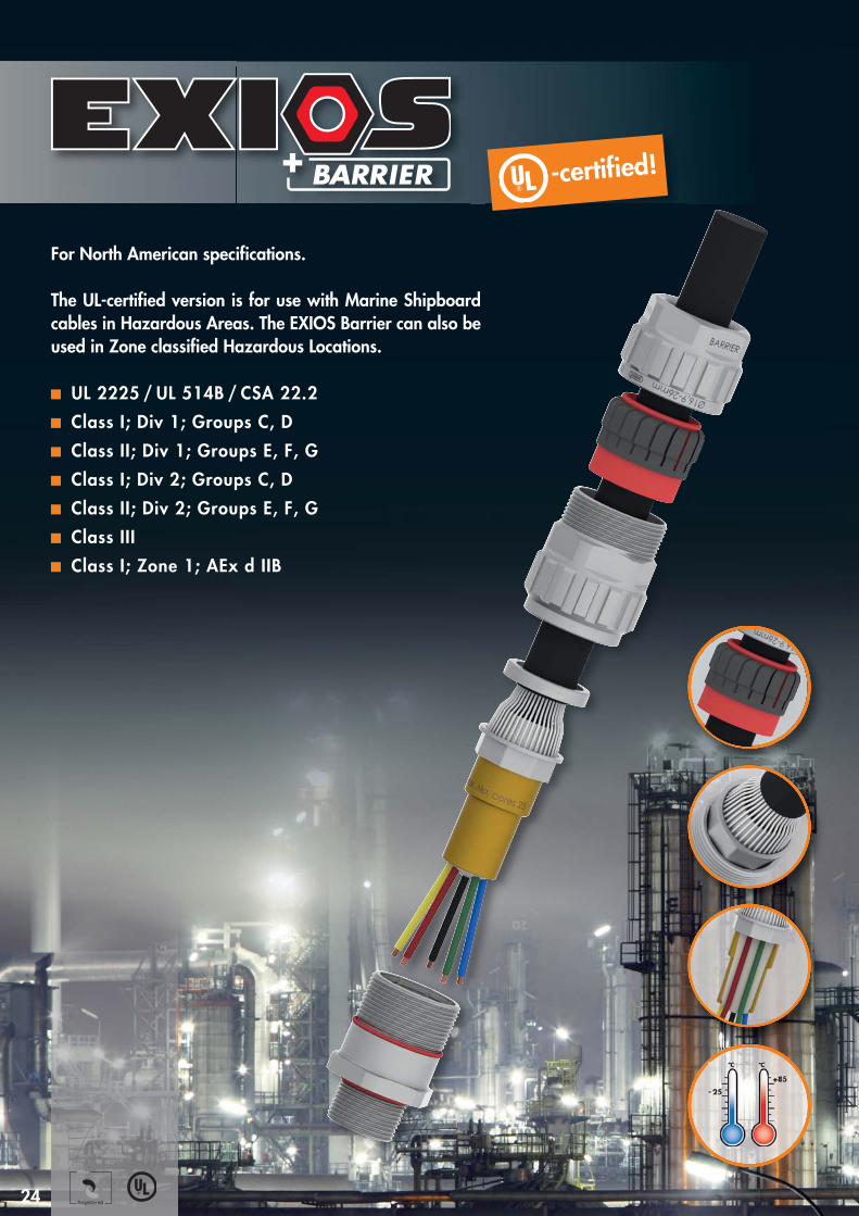
For North American specifications.
The UL-certified version is for use with Marine Shipboardcables in Hazardous Areas. The EXIOS Barrier can also beused in Zone classified Hazardous Locations.
UL 2225 / UL 514B / CSA 22.2Class I; Div 1; Groups C, DClass II; Div 1; Groups E, F, GClass I; Div 2; Groups C, DClass II; Div 2; Groups E, F, GClass IIIClass I; Zone 1; AEx d IIB
A2
A3
AG
GL H
D
A1
Armour mm
Armour mm
1.6U6.1200.70 20 – 2 NPT 1/2" 24 29 68,0 20 9 – 16 12 8,8 10 0 – 0,7 0,7 – 1,25
1.6U6.1200.71 20 – 3 NPT 1/2" 30 35 73,0 20 12,5 – 20,5 14 11,5 15 0 – 0,7 0,7 – 1,4
1.6U6.3400.70 25 NPT 3/4" 36 42 81,3 20,5 16,9 – 26 20 16,4 25 0 – 0,7 0,9 – 1,6
1.6U6.1000.70 32 NPT 1" 46 52 85,5 25 22 – 33 26 21,4 45 0 – 0,7 1,3 – 2,0
1.6U6.5400.70 40 NPT 1 1/4" 55 64 94,4 26 28 – 41 33,2 27,6 70 0 – 0,7 1,3 – 2,0
1.6U6.6400.70 40 NPT 1 1/2" 55 64 94,4 26,5 28 – 41 33,2 27,6 70 0 – 0,7 1,3 – 2,0
1.6U6.2000.70 50 NPT 2" 65 73 116,3 27 36 – 52,6 44,2 37,5 85 0 – 1,0 1,5 – 2,5
1.6U6.5200.70 63 NPT 2 1/2" 80 90 127,6 40 46 – 65,3 56,2 47,3 120 0 – 1,0 1,5 – 2,5
1.6U6.3000.70 75 NPT 3" 95 107 136,5 41,5 57 – 78 68,2 58 150 0 – 1,0 1,5 – 2,5
1.6U6.2000.50 20 – 1 M 20 x 1,5 22 27 69,5 16 6 – 12 8,2 7,9 8 0 – 0,7 0,7 – 1,25
1.6U6.2000.51 20 – 2 M 20 x 1,5 24 29 74,3 16 9 – 16 12 8,8 10 0 – 0,7 0,7 – 1,25
1.6U6.2000.52 20 – 3 M 20 x 1,5 30 35 80,5 16 12,5 – 20,5 14 11,5 15 0 – 0,7 0,7 – 1,4
1.6U6.2500.51 20 – 3 M 25 x 1,5 30 35 80,5 16 12,5 – 20,5 14 11,5 15 0 – 0,7 0,7 – 1,4
1.6U6.2500.50 25 M 25 x 1,5 36 42 91 16 16,9 – 26 20 16,4 25 0 – 0,7 0,9 – 1,6
1.6U6.3200.50 32 M 32 x 1,5 46 52 96 16 22 – 33 26 21,4 45 0 – 0,7 1,3 – 2,0
1.6U6.4000.50 40 M 40 x 1,5 55 64 107 16 28 – 41 33,2 27,6 70 0 – 0,7 1,3 – 2,0
1.6U6.5000.50 50 M 50 x 1,5 65 73 131,5 16 36 – 52,6 44,2 37,5 85 0 – 1,0 1,5 – 2,5
1.6U6.6300.50 63 M 63 x 1,5 80 90 144,5 16 46 – 65,3 56,2 47,3 120 0 – 1,0 1,5 – 2,5
1.6U6.7500.50 75 M 75 x 1,5 95 107 154 16 57 – 78 68,2 58 150 0 – 1,0 1,5 – 2,5
Number Gland AG D H GL A1 A2 max. A3 max. max. Clamping ClampingSize mm mm max. mm mm inner sheath over cores No. cores ring 1 ring 2
Number Gland AG D H GL A1 A2 max. A3 max. max. Clamping ClampingSize mm mm max. mm mm inner sheath over cores No. cores ring 1 ring 2
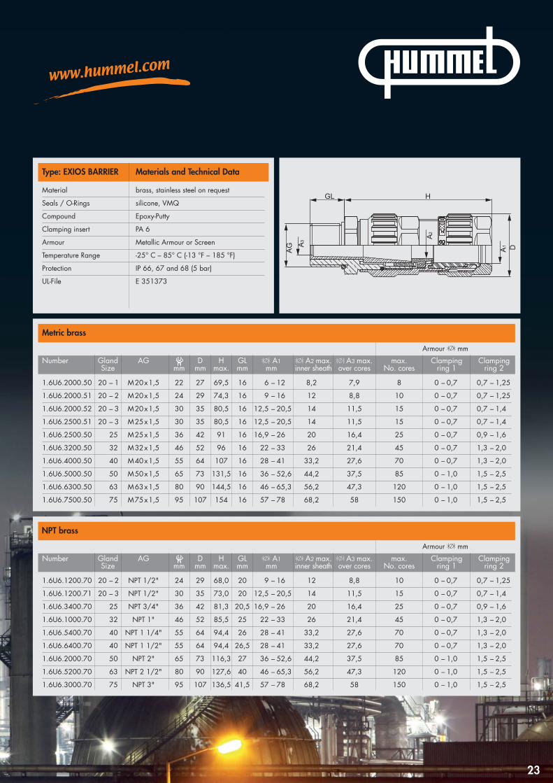
Type: EXIOS BARRIER Materials and Technical Data
Metric brass
NPT brass
23
Material brass, stainless steel on request
Seals / O-Rings silicone, VMQ
Compound Epoxy-Putty
Clamping insert PA 6
Armour Metallic Armour or Screen
Temperature Range -25° C – 85° C (-13 °F – 185 °F)
Protection IP 66, 67 and 68 (5 bar)
UL-File E 351373
–25
°C °C
+ 85
Registered
-certified!
24
For North American specifications.
The UL-certified version is for use with Marine Shipboardcables in Hazardous Areas. The EXIOS Barrier can also beused in Zone classified Hazardous Locations.
UL 2225 / UL 514B / CSA 22.2Class I; Div 1; Groups C, DClass II; Div 1; Groups E, F, GClass I; Div 2; Groups C, DClass II; Div 2; Groups E, F, GClass IIIClass I; Zone 1; AEx d IIB
A2
A3
AG
GL H
D
A1
Armour mm
Armour mm
1.6U6.1203.70 20 – 2 NPT 1/2" 24 29 68,0 20 9 – 16 12 8,8 10 0 – 0,7 0,7 – 1,25
1.6U6.1203.71 20 – 3 NPT 1/2" 30 35 73,0 20 12,5 – 20,5 14 11,5 15 0 – 0,7 0,7 – 1,4
1.6U6.3403.70 25 NPT 3/4" 36 42 81,3 20,5 16,9 – 26 20 16,4 25 0 – 0,7 0,9 – 1,6
1.6U6.1003.70 32 NPT 1" 46 52 85,5 25 22 – 33 26 21,4 45 0 – 0,7 1,3 – 2,0
1.6U6.5403.70 40 NPT 1 1/4" 55 64 94,4 26 28 – 41 33,2 27,6 70 0 – 0,7 1,3 – 2,0
1.6U6.6403.70 40 NPT 1 1/2" 55 64 94,4 26,5 28 – 41 33,2 27,6 70 0 – 0,7 1,3 – 2,0
1.6U6.2003.70 50 NPT 2" 65 73 116,3 27 36 – 52,6 44,2 37,5 85 0 – 1,0 1,5 – 2,5
1.6U6.5203.70 63 NPT 2 1/2" 80 90 127,6 40 46 – 65,3 56,2 47,3 120 0 – 1,0 1,5 – 2,5
1.6U6.3003.70 75 NPT 3" 95 107 136,5 41,5 57 – 78 68,2 58 150 0 – 1,0 1,5 – 2,5
1.6U6.2003.50 20 – 1 M 20 x 1,5 22 27 69,5 16 6 – 12 8,2 7,9 8 0 – 0,7 0,7 – 1,25
1.6U6.2003.51 20 – 2 M 20 x 1,5 24 29 74,3 16 9 – 16 12 8,8 10 0 – 0,7 0,7 – 1,25
1.6U6.2003.52 20 – 3 M 20 x 1,5 30 35 80,5 16 12,5 – 20,5 14 11,5 15 0 – 0,7 0,7 – 1,4
1.6U6.2503.51 20 – 3 M 25 x 1,5 30 35 80,5 16 12,5 – 20,5 14 11,5 15 0 – 0,7 0,7 – 1,4
1.6U6.2503.50 25 M 25 x 1,5 36 42 91 16 16,9 – 26 20 16,4 25 0 – 0,7 0,9 – 1,6
1.6U6.3203.50 32 M 32 x 1,5 46 52 96 16 22 – 33 26 21,4 45 0 – 0,7 1,3 – 2,0
1.6U6.4003.50 40 M 40 x 1,5 55 64 107 16 28 – 41 33,2 27,6 70 0 – 0,7 1,3 – 2,0
1.6U6.5003.50 50 M 50 x 1,5 65 73 131,5 16 36 – 52,6 44,2 37,5 85 0 – 1,0 1,5 – 2,5
1.6U6.6303.50 63 M 63 x 1,5 80 90 144,5 16 46 – 65,3 56,2 47,3 120 0 – 1,0 1,5 – 2,5
1.6U6.7503.50 75 M 75 x 1,5 95 107 154 16 57 – 78 68,2 58 150 0 – 1,0 1,5 – 2,5
Number Gland AG D H GL A1 A2 max. A3 max. max. Clamping ClampingSize mm mm max. mm mm inner sheath over cores No. cores ring 1 ring 2
Number Gland AG D H GL A1 A2 max. A3 max. max. Clamping ClampingSize mm mm max. mm mm inner sheath over cores No. cores ring 1 ring 2
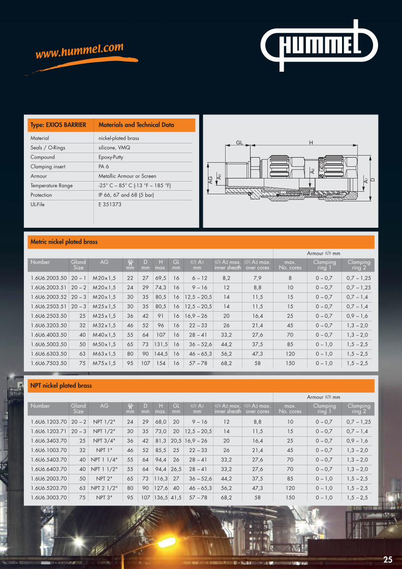
Type: EXIOS BARRIER Materials and Technical Data
Metric nickel plated brass
NPT nickel plated brass
25
Material nickel-plated brass
Seals / O-Rings silicone, VMQ
Compound Epoxy-Putty
Clamping insert PA 6
Armour Metallic Armour or Screen
Temperature Range -25° C – 85° C (-13 °F – 185 °F)
Protection IP 66, 67 and 68 (5 bar)
UL-File E 351373

Red fibre washer
Metric Item No. NPT Item No.
M 16 1.326.1600.50 1/2" 1.326.1200.70
M 20 1.326.2000.50 3/4" 1.326.3400.70
M 25 1.326.2500.50 1" 1.326.1000.70
M 32 1.326.3200.50 1 1/4" 1.326.5400.70
M 40 1.326.4000.50 1 1/2" 1.326.6400.70
M 50 1.326.5000.50 2" 1.326.2000.70
M 63 1.326.6300.50 2 1/2" 1.326.5200.70
M 75 1.326.7500.50 3" 1.326.3000.70
Earth tag brass
Metric Item No. NPT Item No.
M 16 1.022.1600.50 1/2" 1.022.1200.70
M 20 1.022.2000.50 3/4" 1.022.3400.70
M 25 1.022.2500.50 1" 1.022.1000.70
M 32 1.022.3200.50 1 1/4" 1.022.5400.70
M 40 1.022.4000.50 1 1/2" 1.022.6400.70
M 50 1.022.5000.50 2" 1.022.2000.70
M 63 1.022.6300.50 2 1/2" 1.022.5200.70
M 75 1.022.7500.50 3" 1.022.3000.70
D1
PVC shroud (LSF upon request)
EXIOS Size Item No.
20 – 1 1.802.2000.50
20 – 2 1.802.2000.51
20 – 3 1.802.2000.52
25 1.802.2500.50
32 1.802.3200.50
40 1.802.4000.50
50 1.802.5000.50
63 1.802.6300.50
75 1.802.7500.50
26
Accessories
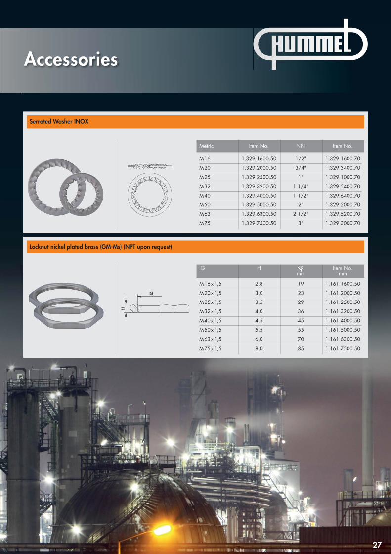
Serrated Washer INOX
Metric Item No. NPT Item No.
M 16 1.329.1600.50 1/2" 1.329.1600.70
M 20 1.329.2000.50 3/4" 1.329.3400.70
M 25 1.329.2500.50 1" 1.329.1000.70
M 32 1.329.3200.50 1 1/4" 1.329.5400.70
M 40 1.329.4000.50 1 1/2" 1.329.6400.70
M 50 1.329.5000.50 2" 1.329.2000.70
M 63 1.329.6300.50 2 1/2" 1.329.5200.70
M 75 1.329.7500.50 3" 1.329.3000.70
Locknut nickel plated brass (GM-Ms) (NPT upon request)
IG H Item No.mm mm
M 16 x 1,5 2,8 19 1.161.1600.50
M 20 x 1,5 3,0 23 1.161.2000.50
M 25 x 1,5 3,5 29 1.161.2500.50
M 32 x 1,5 4,0 36 1.161.3200.50
M 40 x 1,5 4,5 45 1.161.4000.50
M 50 x 1,5 5,5 55 1.161.5000.50
M 63 x 1,5 6,0 70 1.161.6300.50
M 75 x 1,5 8,0 85 1.161.7500.50
27
Accessories
For HUMMEL Sales offices and Distributorsplease see our website.
Tel. +49 (0)76 66 /9 11 10-0Fax +49 (0)76 66 /9 11 10-20E-Mail [email protected]
inte
rmed
ia 0
615
HUMMEL AGLise-Meitner-Straße 279211 DenzlingenGermanywww.hummel.com
HUMMEL International
Europe
HUMMEL France
HUMMEL s.a.r.l.4, rue des fleurs68190 Ungersheim / France
Tel. +33 (0) 3 89 / 55 37 20Fax +33 (0) 3 89 / 53 80 27 E-Mail [email protected]
HUMMEL UK
HUMMEL UK LimitedOffice 3, Momentum HouseEnterprise Way, Lowton St Marys, Warrington, Cheshire, WA3 2BPUnited Kingdom
Tel. +44 (0) 19 42 / 60 56 95Fax +44 (0) 19 42 / 67 20 27E-Mail [email protected]
HUMMEL Italy
HUMMEL s.r.l.Via Valdellatorre 18210091 Alpignano (Torino)/ Italy
Tel. +39 / (0 ) 11 / 9 68 26 38 Fax +39 / (0) 11 / 9 78 55 50E-Mail [email protected]
HUMMEL Poland
HUMMEL Sales Office PolandAl. 23 Stycznia 26 lok. 2086-300 Grudziadz/Polen
Tel. +48 (662) 38 27 99Fax +48 (56)643 00 11E-Mail [email protected]
HUMMEL Russia
OOO HUMMELRetschnikow 21, Strojenije 1 115142 Moskau / Russia
Tel. +7 / 499 / 7 82 - 40 75Fax +7 / 499 / 6 14 - 67 40E-Mail [email protected]
HUMMEL Scandinavia
HUMMEL Connector Systems ABOxtorgsgatan 355317 Jönköping / Sweden
Tel. +46 (0) 73 / 800 12 00E-Mail [email protected]
HUMMEL Hungary
HUMMEL Ungarn Kft.Ko’ rösi út 49.2360 Gyál / Hungary
Tel. +36 / 29 54 06 33Fax +36 / 29 54 06 35E-Mail [email protected]
Asia
HUMMEL China
HUMMEL Connector Systems (Shanghai) Co., Ltd.Room 1701 Central PlazaNo.227 Huang Pi (N) Road200003 Shanghai / P.R. China
Tel. +86 / 21 63 75 85-51Fax +86 / 21 63 75 85-53E-Mail [email protected]
HUMMEL India
HUMMEL Connector Systems Pvt. Ltd.1211, Surya Kiran Building, 19, Kasturba Gandhi Marg110001 New Delhi/India
Tel. +91/11/ 430075-21/- 23Fax +91/11/430075-22E-Mail [email protected]
HUMMEL Kazakhstan
HUMMEL Sales Office KasachstanTurksibskij rayon, Mikrorayon Zhuldyz-1, dom 6, kwartira 19050049 Almaty / Kasachstan
Tel. +7 701 7262004E-Mail [email protected]
HUMMEL South Korea
HUMMEL AG Korea Branch#628 Ssangyong Platinum River,659, Olympic-ro,Gangdong-gu, Seoul,134-874 Korea
Tel. +82 (0) 2 470 2762Fax +82 (0) 2 470 2763E-Mail [email protected]
South America
HUMMEL Brazil
HUMMEL Connector Systems Ltda.Rua Derville Gabriel Pereira, 280Barro Preto – Centro Empresarial Tatuí I CEP 18280-614 - Tatuí / SP / Brazil
Tel. +55 (15) 33 22-70 00Fax +55 (15) 33 22-70 26E-Mail [email protected]


![ADDIMAX CABLE GLANDS FOR INDUSTRIAL USE CABLE GLANDS Glands/Cable Glands.pdf · CABLE GLANDS FOR INDUSTRIAL USE [ 7 ] Ordering Code (Gland Type / Size & Entry Thread Size), e.g. CW](https://img.pdfslide.us/doc/110x75/5f045f7d7e708231d40da7c8/addimax-cable-glands-for-industrial-use-cable-glandscable-glandspdf-cable-glands.jpg)