Embed Size (px)
Citation preview
Fall 2003 1
This article provides an insight into some of the more commonly used and successful cable diagnostic techniques commercially available for performing tests in the fi eld on extruded, medium-voltage, shielded
power cables.
The objective of any diagnostic test is to identify, in a nondestructive way, a potential problem that may exist in a piece of equipment, so that preventative action may be taken to avoid a possible in-service failure of that piece of equipment. With regard to cables, this assessment applies both to the cable itself, as well as the associated accessories (splices and terminations) — referred to as the “cable system.”
Field diagnostic tests can be performed on cables during various stages of their existence. As defi ned by the newly revised IEEE 400 standard, these tests are defi ned as follows: • Installation Test: Conducted after the cable is installed but before any
accessories (joints/splices and terminations) are installed. These tests are intended to detect any manufacturing, transport, and installation damage that may have occurred to the cable.
• Acceptance Test: Performed after the installation of all cable and acces-sories, but before energizing the cable with system voltage. Its purpose is to detect shipping and installation damage in both the cable and cable accessories. Also referred to as an “after-laying test.”
• Maintenance Test: Performed during the operating life of the cable sys-tem. Its purpose is to assess the condition and check the serviceability of the cable system so that suitable maintenance procedures can be initiated.
Cable Field Test CategoriesThese cable fi eld tests can be broadly divided in two main groups,
Type 1 and Type 2 (Ref: IEEE 400).Type 1 Field Tests: These tests are normally performed at elevated volt-
ages and are a pass/fail type test. The traditional high-potential test is an example of a Type 1 fi eld test. The high-potential test can be performed using one of several voltage excitation sources, such as direct current (not suitable for solid dielectric cables) or alternating current (power frequency and very low frequency). The cable either passes or fails the test, but one establishes little knowledge of the condition of the cable other than whether the cable system withstood the voltage for the dura-tion of the test or not. This test is benefi cial in that it is normally able to
root out severe defects in a cable. Many defects, however, may pass undetected during a pure voltage-withstand test.
Type 2 Field Tests: These cable diagnostic tests are performed at test voltages above and/or below the normal operating voltage of the cable. These tests assess the condi-tion of the cable system and try to establish the remaining service life. There are two categories of Type 2 cable diagnostic tests available: • Those that assess the overall
(integral) condition of the cable. Often referred to as “global con-dition assessment.” Example: dissipation factor (also called tangent delta or tan delta).
• Those that detect and locate discrete defect locations in a cable system. Example: partial discharge.
Field Cable DiagnosticsIn recent years, a great deal of
research and development has focused on fi eld cable diagnostic
Diagnostics Field Testing of Medium-Voltage Cables
by Craig GoodwinHV Diagnostics, Inc.
Special Feature
2 NETA WORLD Fall 2003 3
testing. This effort was due in part to the fact that many of the new polyethylene (PE) and cross-linked polyethylene (XLPE) cable systems installed in the late sixties, seventies, and early eighties were not lasting nearly as long as their paper-insulated lead covered (PILC) predecessors. Traditional direct current high-potential testing was not only found to be ineffective in trying to diagnose the failure mechanism before cable failure occurred, but the presence of these el-evated direct current test voltages was also found to be potentially damaging to these service-aged cables. Whereas many PILC cables were lasting well over 50 years before being replaced, some of the originally installed PE/XLPE cables were not even making it to their 10th birthday. A concerted effort to determine and diagnose the root cause of these cable failures in the field was therefore undertaken.
To determine which cable diagnostic technique to apply to a particular cable system, the type of cable insulation is an important criterion. As far as cable diagnostics are concerned, there are two main cable insulation groups to consider: • Extruded/Solid Dielectric Cable: These cables include
PE, XLPE, and Ethylene Propylene Rubber (also known as EPR or “rubber”) cables.
• Laminated Cable: These are cables whose insulation is made up of laminated layers. These cables include PILC. Diagnostic test results, their interpretation, and the
failure mechanisms responsible for each of the above insulation groups vary significantly. For example, a PILC cable may tolerate very high partial discharges for several years before failure occurs (if failure oc-curs at all), while partial discharge in the insulation of an XLPE insulated cable may result in imminent failure and, therefore, require more immediate atten-tion. This article will focus mainly on extruded cables, with which most readers will be more familiar.
Water TreesThe number one cause of insulation aging and
subsequent failures of extruded cables is water trees. Water trees are the “cancer” of extruded cables, such as XLPE and EPR. Water trees are tree-like structures which, through a process of electrophoresis, grow and mature in extruded cables. It is interesting to note that water trees do not occur in PILC cables.
What causes water trees to grow in extruded cable? Four factors need to be present in order for water trees to establish and grow in extruded cable insulation. • Electrical Field: Usually the applied operating volt-
age on the cable. If no voltage is applied to the cable, no water trees will form.
• Time: A relatively slow process, taking several years.
• Water
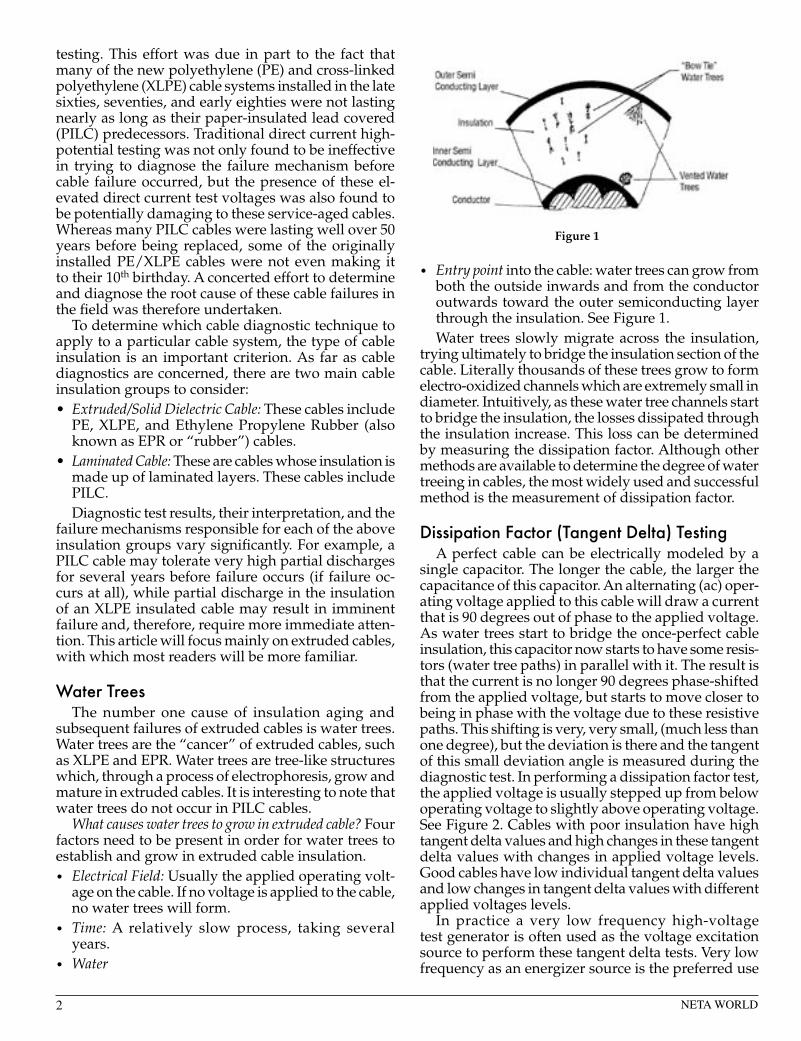
• Entry point into the cable: water trees can grow from both the outside inwards and from the conductor outwards toward the outer semiconducting layer through the insulation. See Figure 1.Water trees slowly migrate across the insulation,
trying ultimately to bridge the insulation section of the cable. Literally thousands of these trees grow to form electro-oxidized channels which are extremely small in diameter. Intuitively, as these water tree channels start to bridge the insulation, the losses dissipated through the insulation increase. This loss can be determined by measuring the dissipation factor. Although other methods are available to determine the degree of water treeing in cables, the most widely used and successful method is the measurement of dissipation factor.
Dissipation Factor (Tangent Delta) Testing A perfect cable can be electrically modeled by a
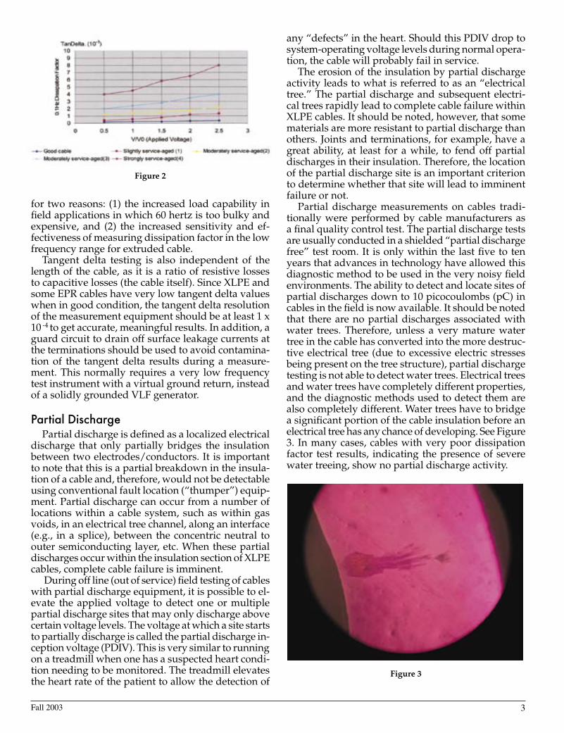
single capacitor. The longer the cable, the larger the capacitance of this capacitor. An alternating (ac) oper-ating voltage applied to this cable will draw a current that is 90 degrees out of phase to the applied voltage. As water trees start to bridge the once-perfect cable insulation, this capacitor now starts to have some resis-tors (water tree paths) in parallel with it. The result is that the current is no longer 90 degrees phase-shifted from the applied voltage, but starts to move closer to being in phase with the voltage due to these resistive paths. This shifting is very, very small, (much less than one degree), but the deviation is there and the tangent of this small deviation angle is measured during the diagnostic test. In performing a dissipation factor test, the applied voltage is usually stepped up from below operating voltage to slightly above operating voltage. See Figure 2. Cables with poor insulation have high tangent delta values and high changes in these tangent delta values with changes in applied voltage levels. Good cables have low individual tangent delta values and low changes in tangent delta values with different applied voltages levels.
In practice a very low frequency high-voltage test generator is often used as the voltage excitation source to perform these tangent delta tests. Very low frequency as an energizer source is the preferred use
Figure 1
2 NETA WORLD Fall 2003 3
for two reasons: (1) the increased load capability in field applications in which 60 hertz is too bulky and expensive, and (2) the increased sensitivity and ef-fectiveness of measuring dissipation factor in the low frequency range for extruded cable.
Tangent delta testing is also independent of the length of the cable, as it is a ratio of resistive losses to capacitive losses (the cable itself). Since XLPE and some EPR cables have very low tangent delta values when in good condition, the tangent delta resolution of the measurement equipment should be at least 1 x 10 -4 to get accurate, meaningful results. In addition, a guard circuit to drain off surface leakage currents at the terminations should be used to avoid contamina-tion of the tangent delta results during a measure-ment. This normally requires a very low frequency test instrument with a virtual ground return, instead of a solidly grounded VLF generator.
Partial Discharge Partial discharge is defined as a localized electrical
discharge that only partially bridges the insulation between two electrodes/conductors. It is important to note that this is a partial breakdown in the insula-tion of a cable and, therefore, would not be detectable using conventional fault location (“thumper”) equip-ment. Partial discharge can occur from a number of locations within a cable system, such as within gas voids, in an electrical tree channel, along an interface (e.g., in a splice), between the concentric neutral to outer semiconducting layer, etc. When these partial discharges occur within the insulation section of XLPE cables, complete cable failure is imminent.
During off line (out of service) field testing of cables with partial discharge equipment, it is possible to el-evate the applied voltage to detect one or multiple partial discharge sites that may only discharge above certain voltage levels. The voltage at which a site starts to partially discharge is called the partial discharge in-ception voltage (PDIV). This is very similar to running on a treadmill when one has a suspected heart condi-tion needing to be monitored. The treadmill elevates the heart rate of the patient to allow the detection of
any “defects” in the heart. Should this PDIV drop to system-operating voltage levels during normal opera-tion, the cable will probably fail in service.
The erosion of the insulation by partial discharge activity leads to what is referred to as an “electrical tree.” The partial discharge and subsequent electri-cal trees rapidly lead to complete cable failure within XLPE cables. It should be noted, however, that some materials are more resistant to partial discharge than others. Joints and terminations, for example, have a great ability, at least for a while, to fend off partial discharges in their insulation. Therefore, the location of the partial discharge site is an important criterion to determine whether that site will lead to imminent failure or not.
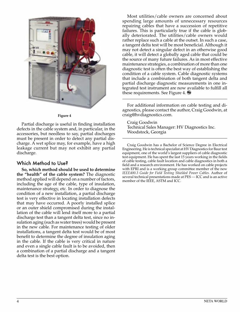
Partial discharge measurements on cables tradi-tionally were performed by cable manufacturers as a final quality control test. The partial discharge tests are usually conducted in a shielded “partial discharge free” test room. It is only within the last five to ten years that advances in technology have allowed this diagnostic method to be used in the very noisy field environments. The ability to detect and locate sites of partial discharges down to 10 picocoulombs (pC) in cables in the field is now available. It should be noted that there are no partial discharges associated with water trees. Therefore, unless a very mature water tree in the cable has converted into the more destruc-tive electrical tree (due to excessive electric stresses being present on the tree structure), partial discharge testing is not able to detect water trees. Electrical trees and water trees have completely different properties, and the diagnostic methods used to detect them are also completely different. Water trees have to bridge a significant portion of the cable insulation before an electrical tree has any chance of developing. See Figure 3. In many cases, cables with very poor dissipation factor test results, indicating the presence of severe water treeing, show no partial discharge activity.
Figure 2
Figure 3
4 NETA WORLD
Partial discharge is useful in finding installation defects in the cable system and, in particular, in the accessories, but needless to say, partial discharges must be present in order to detect any partial dis-charge. A wet splice may, for example, have a high leakage current but may not exhibit any partial discharge.
Which Method to Use?So, which method should be used to determine
the “health” of the cable system? The diagnostic method applied will depend on a number of factors, including the age of the cable, type of insulation, maintenance strategy, etc. In order to diagnose the condition of a new installation, a partial discharge test is very effective in locating installation defects that may have occurred. A poorly installed splice or an outer shield compromised during the instal-lation of the cable will lend itself more to a partial discharge test than a tangent delta test, since no in-sulation aging (such as water trees) would be present in the new cable. For maintenance testing of older installations, a tangent delta test would be of most benefit to determine the degree of insulation aging in the cable. If the cable is very critical in nature and even a single cable fault is to be avoided, then a combination of a partial discharge and a tangent delta test is the best option.
Most utilities/cable owners are concerned about spending large amounts of unnecessary resources repairing cables that have a succession of repetitive failures. This is particularly true if the cable is glob-ally deteriorated. The utilities/cable owners would rather replace such a cable at the outset. In such a case, a tangent delta test will be most beneficial. Although it may not detect a singular defect in an otherwise good cable, it will detect a globally aged cable that could be the source of many future failures. As in most effective maintenance strategies, a combination of more than one diagnostic test is often the best way of establishing the condition of a cable system. Cable diagnostic systems that include a combination of both tangent delta and partial discharge diagnostic measurements in one in-tegrated test instrument are now available to fulfill all these requirements. See Figure 4.
For additional information on cable testing and di-agnostics, please contact the author, Craig Goodwin, at [email protected].
Craig GoodwinTechnical Sales Manager: HV Diagnostics Inc. Woodstock, Georgia
Craig Goodwin has a Bachelor of Science Degree in Electrical Engineering. He is technical specialist at HV Diagnostics for Baur test equipment, one of the world’s largest suppliers of cable diagnostic test equipment. He has spent the last 15 years working in the fields of cable testing, cable fault location and cable diagnostics in both a field and a research environment. He has worked on cable projects with EPRI and is a working group committee member of the new IEEE400.3 Guide for Field Testing Shielded Power Cables. Author of several technical presentations made at PES — ICC and is an active member of the IEEE, ASTM and ICC.
Figure 4