Embed Size (px)
Citation preview
Cable Commands: show ch through show cr
• show checkpoint, on page 2• show cmts ipc-cable client base, on page 9• show controller gigabitethernet, on page 14• show controller integrated-cable, on page 16• show controller tengigabitethernet, on page 48• show controllers cable, on page 54• show controllers cable jib, on page 76• show controllers cable upstream spectrum, on page 83• show controllers clock-reference, on page 88• show controllers downstream-cable, on page 94• show controllers jacket, on page 97• show controllers modular-cable, on page 99• show controllers upstream-cable, on page 112• show cpd, on page 115• show cr10k-rp cable, on page 116• show cr10k-rp controller, on page 120• show cr10k-rp queue, on page 123• show cr10k-rp slots, on page 126
Cable Commands: show ch through show cr1
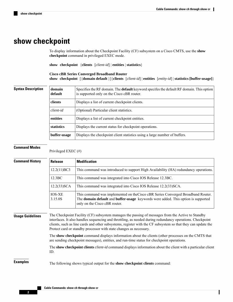
show checkpointTo display information about the Checkpoint Facility (CF) subsystem on a Cisco CMTS, use the showcheckpoint command in privileged EXEC mode.
show checkpoint {clients [client-id] | entities | statistics}
Cisco cBR Series Converged Broadband Routershow checkpoint [{domain default }]{clients [client-id] | entities [entity-id] | statistics [buffer-usage]}
Syntax Description Specifies the RF domain. The default keyword specifes the default RF domain. This optionis supported only on the Cisco cBR router.
domaindefault
Displays a list of current checkpoint clients.clients
(Optional) Particular client statistics.client-id
Displays a list of current checkpoint entities.entities
Displays the current status for checkpoint operations.statistics
Displays the checkpoint client statistics using a large number of buffers.buffer-usage
Command ModesPrivileged EXEC (#)
Command History ModificationRelease
This command was introduced to support High Availability (HA) redundancy operations.12.2(11)BC3
This command was integrated into Cisco IOS Release 12.3BC.12.3BC
This command was integrated into Cisco IOS Release 12.2(33)SCA.12.2(33)SCA
This command was implemented on theCisco cBR Series Converged Broadband Router.The domain default and buffer-usage keywords were added. This option is supportedonly on the Cisco cBR router.
IOS-XE3.15.0S
Usage Guidelines The Checkpoint Facility (CF) subsystem manages the passing of messages from the Active to Standbyinterfaces. It also handles sequencing and throttling, as needed during redundancy operations. Checkpointclients, such as line cards and other subsystems, register with the CF subsystem so that they can update theProtect card or standby processor with state changes as necessary.
The show checkpoint command displays information about the clients (other processes on the CMTS thatare sending checkpoint messages), entities, and run-time status for checkpoint operations.
The show checkpoint clients client-id command displays information about the client with a particular clientID.
Examples The following shows typical output for the show checkpoint clients command:
Cable Commands: show ch through show cr2
Cable Commands: show ch through show crshow checkpoint
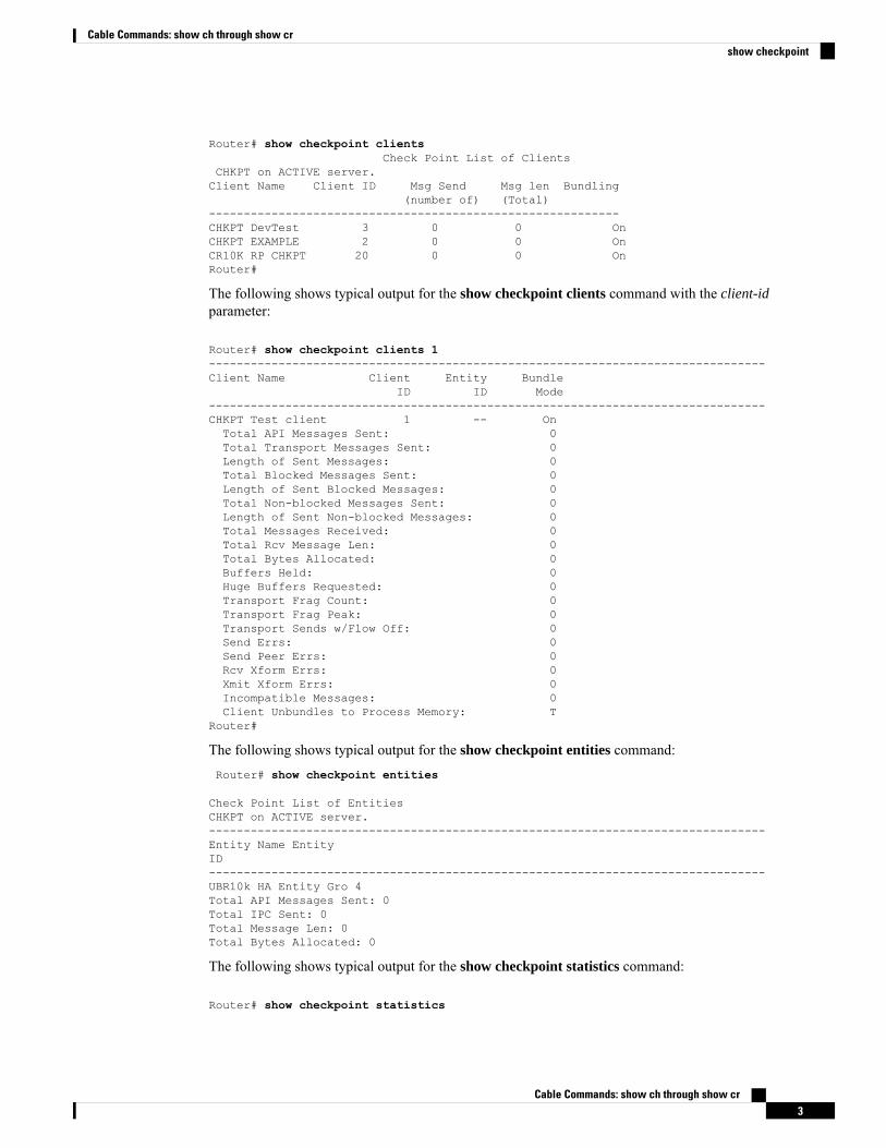
Router# show checkpoint clientsCheck Point List of Clients
CHKPT on ACTIVE server.Client Name Client ID Msg Send Msg len Bundling
(number of) (Total)-----------------------------------------------------------CHKPT DevTest 3 0 0 OnCHKPT EXAMPLE 2 0 0 OnCR10K RP CHKPT 20 0 0 OnRouter#
The following shows typical output for the show checkpoint clients command with the client-idparameter:
Router# show checkpoint clients 1--------------------------------------------------------------------------------Client Name Client Entity Bundle
ID ID Mode--------------------------------------------------------------------------------CHKPT Test client 1 -- OnTotal API Messages Sent: 0Total Transport Messages Sent: 0Length of Sent Messages: 0Total Blocked Messages Sent: 0Length of Sent Blocked Messages: 0Total Non-blocked Messages Sent: 0Length of Sent Non-blocked Messages: 0Total Messages Received: 0Total Rcv Message Len: 0Total Bytes Allocated: 0Buffers Held: 0Huge Buffers Requested: 0Transport Frag Count: 0Transport Frag Peak: 0Transport Sends w/Flow Off: 0Send Errs: 0Send Peer Errs: 0Rcv Xform Errs: 0Xmit Xform Errs: 0Incompatible Messages: 0Client Unbundles to Process Memory: T
Router#
The following shows typical output for the show checkpoint entities command:Router# show checkpoint entities
Check Point List of EntitiesCHKPT on ACTIVE server.--------------------------------------------------------------------------------Entity Name EntityID--------------------------------------------------------------------------------UBR10k HA Entity Gro 4Total API Messages Sent: 0Total IPC Sent: 0Total Message Len: 0Total Bytes Allocated: 0
The following shows typical output for the show checkpoint statistics command:
Router# show checkpoint statistics
Cable Commands: show ch through show cr3
Cable Commands: show ch through show crshow checkpoint
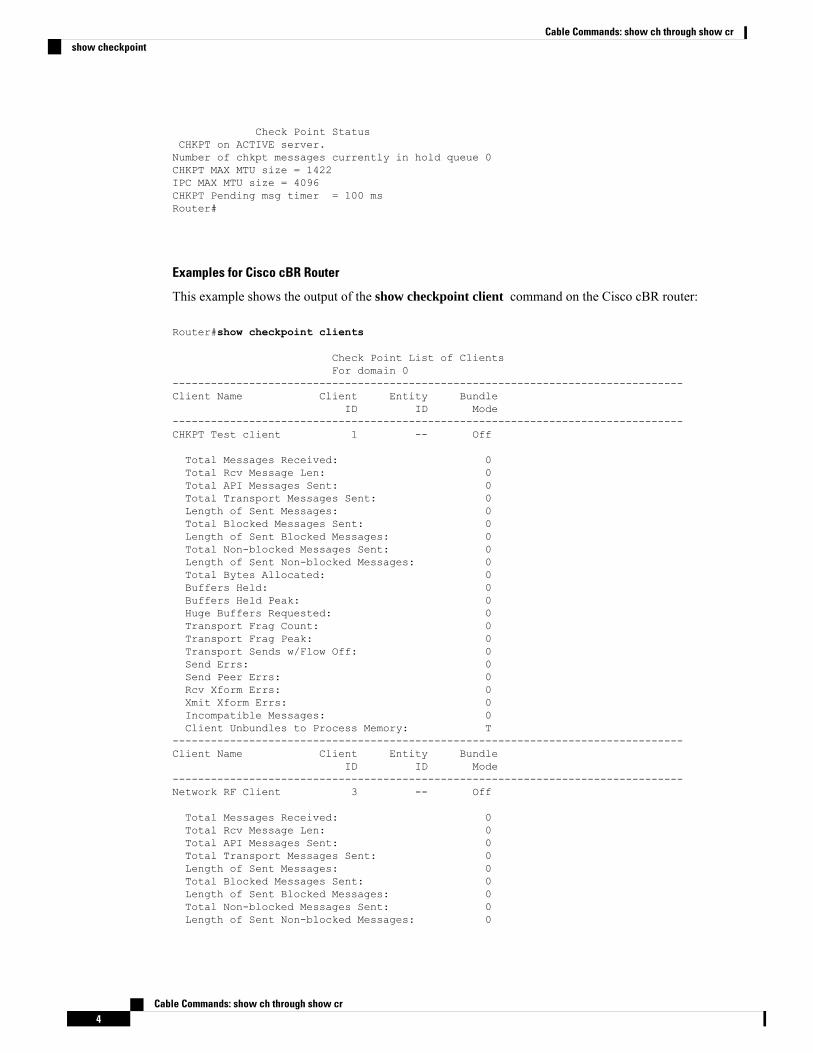
Check Point StatusCHKPT on ACTIVE server.Number of chkpt messages currently in hold queue 0CHKPT MAX MTU size = 1422IPC MAX MTU size = 4096CHKPT Pending msg timer = 100 msRouter#
Examples for Cisco cBR Router
This example shows the output of the show checkpoint client command on the Cisco cBR router:
Router#show checkpoint clients
Check Point List of ClientsFor domain 0
--------------------------------------------------------------------------------Client Name Client Entity Bundle
ID ID Mode--------------------------------------------------------------------------------CHKPT Test client 1 -- Off
Total Messages Received: 0Total Rcv Message Len: 0Total API Messages Sent: 0Total Transport Messages Sent: 0Length of Sent Messages: 0Total Blocked Messages Sent: 0Length of Sent Blocked Messages: 0Total Non-blocked Messages Sent: 0Length of Sent Non-blocked Messages: 0Total Bytes Allocated: 0Buffers Held: 0Buffers Held Peak: 0Huge Buffers Requested: 0Transport Frag Count: 0Transport Frag Peak: 0Transport Sends w/Flow Off: 0Send Errs: 0Send Peer Errs: 0Rcv Xform Errs: 0Xmit Xform Errs: 0Incompatible Messages: 0Client Unbundles to Process Memory: T
--------------------------------------------------------------------------------Client Name Client Entity Bundle
ID ID Mode--------------------------------------------------------------------------------Network RF Client 3 -- Off
Total Messages Received: 0Total Rcv Message Len: 0Total API Messages Sent: 0Total Transport Messages Sent: 0Length of Sent Messages: 0Total Blocked Messages Sent: 0Length of Sent Blocked Messages: 0Total Non-blocked Messages Sent: 0Length of Sent Non-blocked Messages: 0
Cable Commands: show ch through show cr4
Cable Commands: show ch through show crshow checkpoint
Total Bytes Allocated: 0Buffers Held: 0Buffers Held Peak: 0Huge Buffers Requested: 0Transport Frag Count: 0Transport Frag Peak: 0Transport Sends w/Flow Off: 0Send Errs: 0Send Peer Errs: 0Rcv Xform Errs: 0Xmit Xform Errs: 0Incompatible Messages: 0Client Unbundles to Process Memory: T
--------------------------------------------------------------------------------Client Name Client Entity Bundle
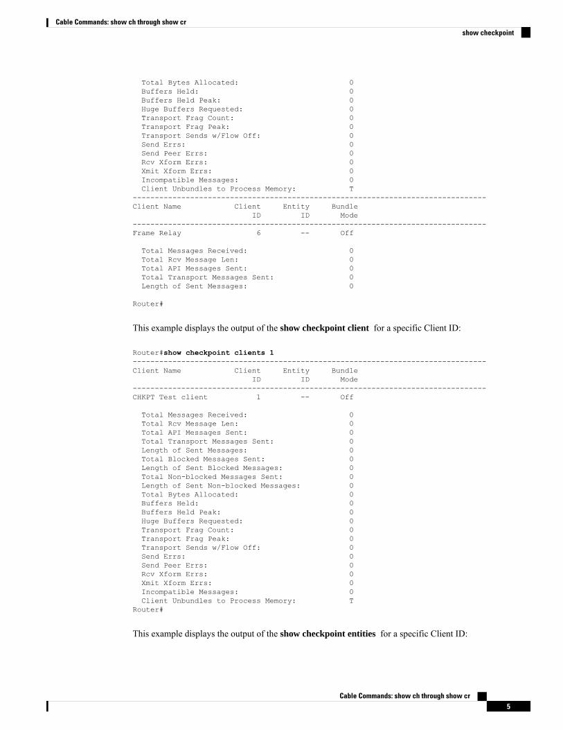
ID ID Mode--------------------------------------------------------------------------------Frame Relay 6 -- Off
Total Messages Received: 0Total Rcv Message Len: 0Total API Messages Sent: 0Total Transport Messages Sent: 0Length of Sent Messages: 0
Router#
This example displays the output of the show checkpoint client for a specific Client ID:
Router#show checkpoint clients 1--------------------------------------------------------------------------------Client Name Client Entity Bundle
ID ID Mode--------------------------------------------------------------------------------CHKPT Test client 1 -- Off
Total Messages Received: 0Total Rcv Message Len: 0Total API Messages Sent: 0Total Transport Messages Sent: 0Length of Sent Messages: 0Total Blocked Messages Sent: 0Length of Sent Blocked Messages: 0Total Non-blocked Messages Sent: 0Length of Sent Non-blocked Messages: 0Total Bytes Allocated: 0Buffers Held: 0Buffers Held Peak: 0Huge Buffers Requested: 0Transport Frag Count: 0Transport Frag Peak: 0Transport Sends w/Flow Off: 0Send Errs: 0Send Peer Errs: 0Rcv Xform Errs: 0Xmit Xform Errs: 0Incompatible Messages: 0Client Unbundles to Process Memory: T
Router#
This example displays the output of the show checkpoint entities for a specific Client ID:
Cable Commands: show ch through show cr5
Cable Commands: show ch through show crshow checkpoint
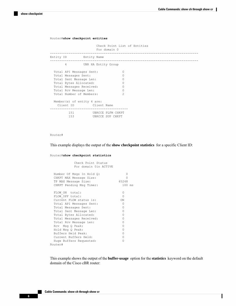
Router#show checkpoint entities
Check Point List of EntitiesFor domain 0
--------------------------------------------------------------------------------Entity ID Entity Name--------------------------------------------------------------------------------
4 UBR HA Entity Group
Total API Messages Sent: 0Total Messages Sent: 0Total Sent Message Len: 0Total Bytes Allocated: 0Total Messages Received: 0Total Rcv Message Len: 0Total Number of Members: 2
Member(s) of entity 4 are:Client ID Client Name
------------------------------------------151 UBRCCE PLFM CHKPT153 UBRCCE SUP CHKPT
Router#
This example displays the output of the show checkpoint statistics for a specific Client ID:
Router#show checkpoint statistics
Check Point StatusFor domain 0in ACTIVE
Number Of Msgs In Hold Q: 0CHKPT MAX Message Size: 0TP MAX Message Size: 65248CHKPT Pending Msg Timer: 100 ms
FLOW_ON total: 0FLOW_OFF total: 0Current FLOW status is: ONTotal API Messages Sent: 0Total Messages Sent: 0Total Sent Message Len: 0Total Bytes Allocated: 0Total Messages Received: 0Total Rcv Message Len: 0Rcv Msg Q Peak: 0Hold Msg Q Peak: 0Buffers Held Peak: 0Current Buffers Held: 0Huge Buffers Requested: 0
Router#
This example shows the output of the buffer-usage option for the statistics keyword on the defaultdomain of the Cisco cBR router:
Cable Commands: show ch through show cr6
Cable Commands: show ch through show crshow checkpoint
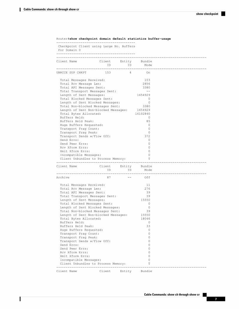
Router#show checkpoint domain default statistics buffer-usage------------------------------------------Checkpoint Client using Large No. BuffersFor Domain 0--------------------------------------------------------------------------------------------------------------------------Client Name Client Entity Bundle
ID ID Mode--------------------------------------------------------------------------------UBRCCE SUP CHKPT 153 4 On
Total Messages Received: 103Total Rcv Message Len: 2856Total API Messages Sent: 3380Total Transport Messages Sent: --Length of Sent Messages: 1654929Total Blocked Messages Sent: 0Length of Sent Blocked Messages: 0Total Non-blocked Messages Sent: 3380Length of Sent Non-blocked Messages: 1654929Total Bytes Allocated: 16102840Buffers Held: 0Buffers Held Peak: 85Huge Buffers Requested: 0Transport Frag Count: 0Transport Frag Peak: 0Transport Sends w/Flow Off: 372Send Errs: 0Send Peer Errs: 0Rcv Xform Errs: 0Xmit Xform Errs: 0Incompatible Messages: 0Client Unbundles to Process Memory: T
--------------------------------------------------------------------------------Client Name Client Entity Bundle
ID ID Mode--------------------------------------------------------------------------------Archive 87 -- Off
Total Messages Received: 11Total Rcv Message Len: 276Total API Messages Sent: 39Total Transport Messages Sent: 39Length of Sent Messages: 15550Total Blocked Messages Sent: 0Length of Sent Blocked Messages: 0Total Non-blocked Messages Sent: 39Length of Sent Non-blocked Messages: 15550Total Bytes Allocated: 18046Buffers Held: 0Buffers Held Peak: 33Huge Buffers Requested: 0Transport Frag Count: 0Transport Frag Peak: 0Transport Sends w/Flow Off: 0Send Errs: 0Send Peer Errs: 0Rcv Xform Errs: 0Xmit Xform Errs: 0Incompatible Messages: 0Client Unbundles to Process Memory: T
--------------------------------------------------------------------------------Client Name Client Entity Bundle
Cable Commands: show ch through show cr7
Cable Commands: show ch through show crshow checkpoint
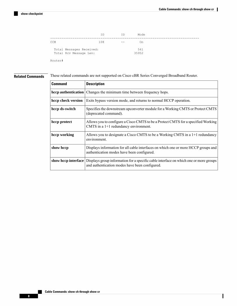
ID ID Mode--------------------------------------------------------------------------------CCM 108 -- On
Total Messages Received: 541Total Rcv Message Len: 35952
Router#
Related Commands These related commands are not supported on Cisco cBR Series Converged Broadband Router.
DescriptionCommand
Changes the minimum time between frequency hops.hccp authentication
Exits bypass version mode, and returns to normal HCCP operation.hccp check version
Specifies the downstream upconverter module for aWorking CMTS or Protect CMTS(deprecated command).
hccp ds-switch
Allows you to configure a Cisco CMTS to be a Protect CMTS for a specifiedWorkingCMTS in a 1+1 redundancy environment.
hccp protect
Allows you to designate a Cisco CMTS to be a Working CMTS in a 1+1 redundancyenvironment.
hccp working
Displays information for all cable interfaces on which one or more HCCP groups andauthentication modes have been configured.
show hccp
Displays group information for a specific cable interface on which one or more groupsand authentication modes have been configured.
show hccp interface
Cable Commands: show ch through show cr8
Cable Commands: show ch through show crshow checkpoint
show cmts ipc-cable client baseTo display the interprocess communication (IPC) session status, the service information for all the slots andsubslots on the line cards, and statistics for each session on the Cisco uBR10012 router, use the show cmtsipc-cable client base command in user EXEC or privileged EXEC mode.
show cmts ipc-cable client base {client | service | stats}
Syntax Description Displays the IPC session status information.client
Displays all the IPC services for the slots and subslots on the Cisco uBR10012 router.service
Displays the IPC layer statistics information for every session.stats
Command Default None
Command ModesUser EXEC (>) or
Privileged EXEC (#)
Command History ModificationRelease
This command was introduced.12.2(33)SCB
The service keyword was added to this command.12.2(33)SCF
This command was removed.IOS-XE3.15.0S
Usage Guidelines The show cmts ipc-cable client base client command displays the IPC session information for a group ofmessages that are exchanged between a route processor (RP) and a line card or between two line cards. Thisinformation includes the client ID, client name, IPC transport information, slot and subslot information, sessionstate to identify whether the session is ready for message exchange, number of messages that are pending,and number of messages dropped.
The show cmts ipc-cable client base service command displays the IPC service information for all the slotsand subslots on the Cisco uBR10012 router. This information includes IPC port information, such as type ofservice and port ID, retry and timeout information of the IPC messages, and watermark information in therequest queue.
The show cmts ipc-cable client base stats command displays the IPC layer error statistics for every sessionand is used for internal debugging purposes. The error statistics information includes the client ID, clientname, transport type, slot and subslot information, client buffer, IPC layer state, error counter information forthe sent and received messages, and IPC In Service Software Upgrade (ISSU) register information.
Examples The following is a sample output of the show cmts ipc-cable client base client command:
Router# show cmts ipc-cable client base client
Cable Commands: show ch through show cr9
Cable Commands: show ch through show crshow cmts ipc-cable client base
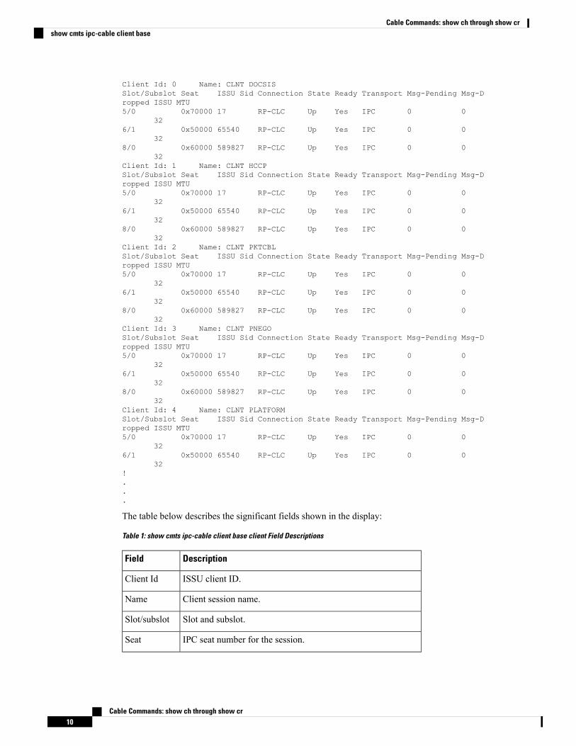
Client Id: 0 Name: CLNT DOCSISSlot/Subslot Seat ISSU Sid Connection State Ready Transport Msg-Pending Msg-Dropped ISSU MTU5/0 0x70000 17 RP-CLC Up Yes IPC 0 0
326/1 0x50000 65540 RP-CLC Up Yes IPC 0 0
328/0 0x60000 589827 RP-CLC Up Yes IPC 0 0
32Client Id: 1 Name: CLNT HCCPSlot/Subslot Seat ISSU Sid Connection State Ready Transport Msg-Pending Msg-Dropped ISSU MTU5/0 0x70000 17 RP-CLC Up Yes IPC 0 0
326/1 0x50000 65540 RP-CLC Up Yes IPC 0 0
328/0 0x60000 589827 RP-CLC Up Yes IPC 0 0
32Client Id: 2 Name: CLNT PKTCBLSlot/Subslot Seat ISSU Sid Connection State Ready Transport Msg-Pending Msg-Dropped ISSU MTU5/0 0x70000 17 RP-CLC Up Yes IPC 0 0
326/1 0x50000 65540 RP-CLC Up Yes IPC 0 0
328/0 0x60000 589827 RP-CLC Up Yes IPC 0 0
32Client Id: 3 Name: CLNT PNEGOSlot/Subslot Seat ISSU Sid Connection State Ready Transport Msg-Pending Msg-Dropped ISSU MTU5/0 0x70000 17 RP-CLC Up Yes IPC 0 0
326/1 0x50000 65540 RP-CLC Up Yes IPC 0 0
328/0 0x60000 589827 RP-CLC Up Yes IPC 0 0
32Client Id: 4 Name: CLNT PLATFORMSlot/Subslot Seat ISSU Sid Connection State Ready Transport Msg-Pending Msg-Dropped ISSU MTU5/0 0x70000 17 RP-CLC Up Yes IPC 0 0
326/1 0x50000 65540 RP-CLC Up Yes IPC 0 0
32!...
The table below describes the significant fields shown in the display:
Table 1: show cmts ipc-cable client base client Field Descriptions
DescriptionField
ISSU client ID.Client Id
Client session name.Name
Slot and subslot.Slot/subslot
IPC seat number for the session.Seat
Cable Commands: show ch through show cr10
Cable Commands: show ch through show crshow cmts ipc-cable client base
DescriptionField
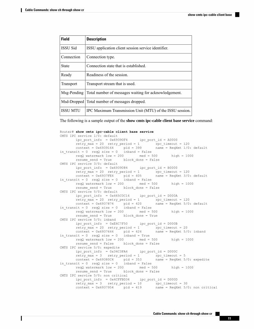
ISSU application client session service identifier.ISSU Sid
Connection type.Connection
Connection state that is established.State
Readiness of the session.Ready
Transport stream that is used.Transport
Total number of messages waiting for acknowledgement.Msg-Pending
Total number of messages dropped.Msd-Dropped
IPC Maximum Transmission Unit (MTU) of the ISSU session.ISSU MTU
The following is a sample output of the show cmts ipc-cable client base service command:
Router# show cmts ipc-cable client base serviceCMTS IPC service 1/0: default
ipc_port_info = 0x69390F4 ipc_port_id = A0000retry_max = 20 retry_period = 1 rpc_timeout = 120context = 0x6939164 pid = 399 name = ReqXmt 1/0: default
in_transit = 0 reqQ size = 0 inband = FalsereqQ watermark low = 200 med = 500 high = 1000resume_send = True block_done = False
CMTS IPC service 3/0: defaultipc_port_info = 0x6939084 ipc_port_id = B0000retry_max = 20 retry_period = 1 rpc_timeout = 120context = 0x6937FE4 pid = 405 name = ReqXmt 3/0: default
in_transit = 0 reqQ size = 0 inband = FalsereqQ watermark low = 200 med = 500 high = 1000resume_send = True block_done = False
CMTS IPC service 5/0: defaultipc_port_info = 0x465C0C14 ipc_port_id = D000Aretry_max = 20 retry_period = 1 rpc_timeout = 120context = 0x6937874 pid = 420 name = ReqXmt 5/0: default
in_transit = 0 reqQ size = 0 inband = FalsereqQ watermark low = 200 med = 500 high = 1000resume_send = True block_done = True
CMTS IPC service 5/0: inbandipc_port_info = 0xE6C7F50 ipc_port_id = D000Bretry_max = 20 retry_period = 1 rpc_timeout = 20context = 0x6937644 pid = 424 name = ReqXmt 5/0: inband
in_transit = 0 reqQ size = 0 inband = TruereqQ watermark low = 200 med = 500 high = 1000resume_send = False block_done = False
CMTS IPC service 5/0: expediteipc_port_info = 0x34C3FA4 ipc_port_id = D000Cretry_max = 3 retry_period = 1 rpc_timeout = 5context = 0x69380C4 pid = 353 name = ReqXmt 5/0: expedite
in_transit = 0 reqQ size = 0 inband = FalsereqQ watermark low = 200 med = 500 high = 1000resume_send = True block_done = False
CMTS IPC service 5/0: non criticalipc_port_info = 0x4CFFBD34 ipc_port_id = D000Dretry_max = 3 retry_period = 10 rpc_timeout = 30context = 0x6937954 pid = 419 name = ReqXmt 5/0: non critical
Cable Commands: show ch through show cr11
Cable Commands: show ch through show crshow cmts ipc-cable client base
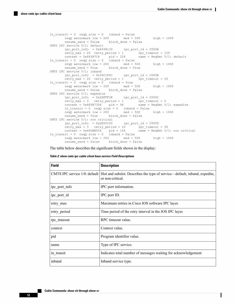
in_transit = 0 reqQ size = 0 inband = FalsereqQ watermark low = 200 med = 500 high = 1000resume_send = False block_done = False
CMTS IPC service 5/1: defaultipc_port_info = 0x6938134 ipc_port_id = C000Aretry_max = 20 retry_period = 1 rpc_timeout = 120context = 0x69387C4 pid = 226 name = ReqXmt 5/1: default
in_transit = 0 reqQ size = 0 inband = FalsereqQ watermark low = 200 med = 500 high = 1000resume_send = True block_done = True
CMTS IPC service 5/1: inbandipc_port_info = 0x34C1F4C ipc_port_id = C000Bretry_max = 20 retry_period = 1 rpc_timeout = 20
in_transit = 0 reqQ size = 0 inband = TruereqQ watermark low = 200 med = 500 high = 1000resume_send = False block_done = False
CMTS IPC service 5/1: expediteipc_port_info = 0x2DFFF38 ipc_port_id = C000Cretry_max = 3 retry_period = 1 rpc_timeout = 5context = 0x465B73D4 pid = 96 name = ReqXmt 5/1: expeditein_transit = 0 reqQ size = 0 inband = FalsereqQ watermark low = 200 med = 500 high = 1000resume_send = True block_done = False
CMTS IPC service 5/1: non criticalipc_port_info = 0x2E00100 ipc_port_id = C000Dretry_max = 3 retry_period = 10 rpc_timeout = 30context = 0x465BE054 pid = 164 name = ReqXmt 5/1: non critical
in_transit = 0 reqQ size = 0 inband = FalsereqQ watermark low = 200 med = 500 high = 1000resume_send = False block_done = False
The table below describes the significant fields shown in the display:
Table 2: show cmts ipc-cable client base service Field Descriptions
DescriptionField
Slot and subslot. Describes the type of service—default, inband, expedite,or non-critical.
CMTS IPC service 1/0: default
IPC port information.ipc_port_info
IPC port ID.ipc_port_id
Maximum retries in Cisco IOS software IPC layer.retry_max
Time period of the retry interval in the IOS IPC layer.retry_period
RPC timeout value.rpc_timeout
Context value.context
Program identifier value.pid
Type of IPC service.name
Indicates total number of messages waiting for acknowledgementin_transit
Inband service type.inband
Cable Commands: show ch through show cr12
Cable Commands: show ch through show crshow cmts ipc-cable client base
DescriptionField
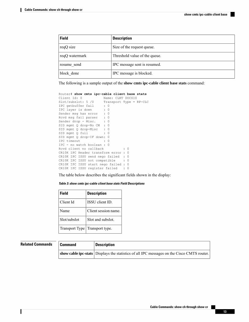
Size of the request queue.reqQ size
Threshold value of the queue.reqQ watermark
IPC message sent is resumed.resume_send
IPC message is blocked.block_done
The following is a sample output of the show cmts ipc-cable client base stats command:
Router# show cmts ipc-cable client base statsClient Id: 0 Name: CLNT DOCSISSlot/subslot: 5 /0 Transport Type = RP-CLCIPC getbuffer fail : 0IPC layer is down : 0Sender msg has error : 0Rcvd msg fail parser : 0Sender drop - Misc. : 0SID mgmt Q drop-No CM : 0SID mgmt Q drop-Misc : 0SID mgmt Q full : 0SID mgmt Q drop-IF down: 0IPC timeout : 0IPC - no watch boolean : 0Rcvd client no callback : 0CR10K IPC Header transform error : 0CR10K IPC ISSU send nego failed : 0CR10K IPC ISSU not compatible : 0CR10K IPC ISSU start nego failed : 0CR10K IPC ISSU register failed : 0
The table below describes the significant fields shown in the display:
Table 3: show cmts ipc-cable client base stats Field Descriptions
DescriptionField
ISSU client ID.Client Id
Client session name.Name
Slot and subslot.Slot/subslot
Transport type.Transport Type
Related Commands DescriptionCommand
Displays the statistics of all IPC messages on the Cisco CMTS router.show cable ipc-stats
Cable Commands: show ch through show cr13
Cable Commands: show ch through show crshow cmts ipc-cable client base
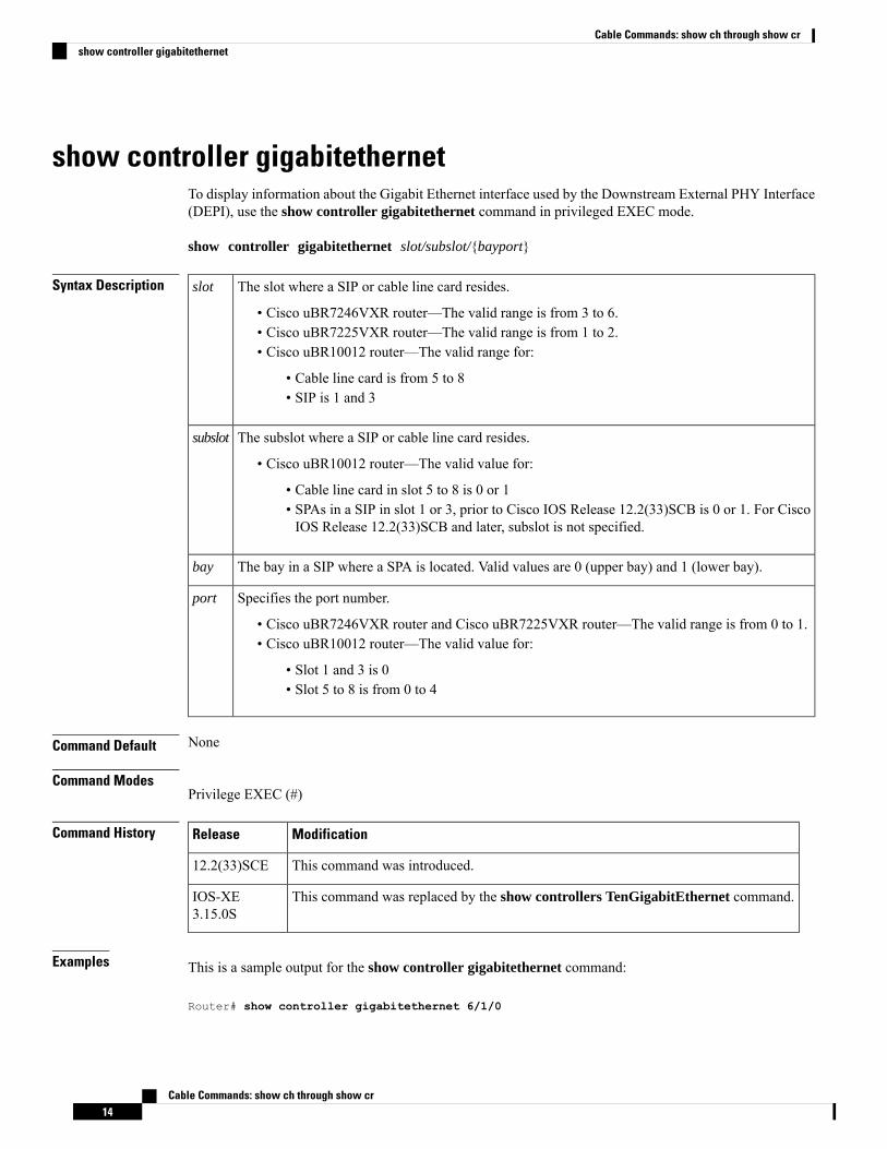
show controller gigabitethernetTo display information about the Gigabit Ethernet interface used by the Downstream External PHY Interface(DEPI), use the show controller gigabitethernet command in privileged EXEC mode.
show controller gigabitethernet slot/subslot/{bayport}
Syntax Description The slot where a SIP or cable line card resides.
• Cisco uBR7246VXR router—The valid range is from 3 to 6.• Cisco uBR7225VXR router—The valid range is from 1 to 2.• Cisco uBR10012 router—The valid range for:
• Cable line card is from 5 to 8• SIP is 1 and 3
slot
The subslot where a SIP or cable line card resides.
• Cisco uBR10012 router—The valid value for:
• Cable line card in slot 5 to 8 is 0 or 1• SPAs in a SIP in slot 1 or 3, prior to Cisco IOS Release 12.2(33)SCB is 0 or 1. For CiscoIOS Release 12.2(33)SCB and later, subslot is not specified.
subslot
The bay in a SIP where a SPA is located. Valid values are 0 (upper bay) and 1 (lower bay).bay
Specifies the port number.
• Cisco uBR7246VXR router and Cisco uBR7225VXR router—The valid range is from 0 to 1.• Cisco uBR10012 router—The valid value for:
• Slot 1 and 3 is 0• Slot 5 to 8 is from 0 to 4
port
Command Default None
Command ModesPrivilege EXEC (#)
Command History ModificationRelease
This command was introduced.12.2(33)SCE
This command was replaced by the show controllers TenGigabitEthernet command.IOS-XE3.15.0S
Examples This is a sample output for the show controller gigabitethernet command:
Router# show controller gigabitethernet 6/1/0
Cable Commands: show ch through show cr14
Cable Commands: show ch through show crshow controller gigabitethernet
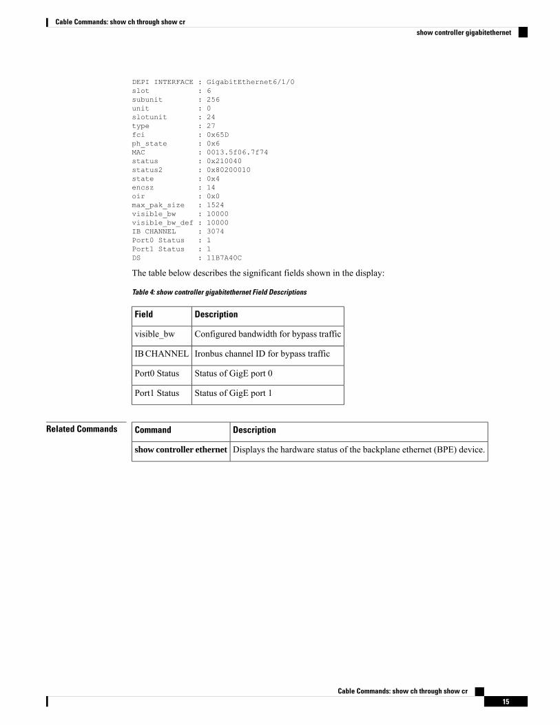
DEPI INTERFACE : GigabitEthernet6/1/0slot : 6subunit : 256unit : 0slotunit : 24type : 27fci : 0x65Dph_state : 0x6MAC : 0013.5f06.7f74status : 0x210040status2 : 0x80200010state : 0x4encsz : 14oir : 0x0max_pak_size : 1524visible_bw : 10000visible_bw_def : 10000IB CHANNEL : 3074Port0 Status : 1Port1 Status : 1DS : 11B7A40C
The table below describes the significant fields shown in the display:
Table 4: show controller gigabitethernet Field Descriptions
DescriptionField
Configured bandwidth for bypass trafficvisible_bw
Ironbus channel ID for bypass trafficIBCHANNEL
Status of GigE port 0Port0 Status
Status of GigE port 1Port1 Status
Related Commands DescriptionCommand
Displays the hardware status of the backplane ethernet (BPE) device.show controller ethernet
Cable Commands: show ch through show cr15
Cable Commands: show ch through show crshow controller gigabitethernet
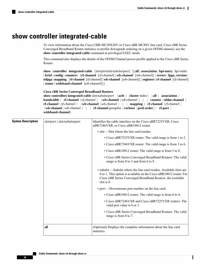
show controller integrated-cableTo view information about the Cisco UBR-MC20X20V or Cisco uBR-MC88V line card, Cisco cBR SeriesConverged Broadband Router statistics or profile downgrade ordering on a given OFDM channel, use theshow controller integrated-cable command in privileged EXEC mode.
This command also displays the details of the OFDM Channel power profile applied to the Cisco cBR SeriesRouter.
show controller integrated-cable {slot/portslot/subslot/port} [{all | association | bpi-entry bpi-index| brief | config | counters {rf-channel [rf-channel] | wb-channel [wb-channel]} | errors | fpga_version |iofpga |mapping {rf-channel [rf-channel] |wb-channel [wb-channel]} | registers | rf-channel [rf-channel]| status | wideband-channel [wb-channel]}]
Cisco cBR Series Converged Broadband Routersshow controllers integrated-cable slot/subslot/port {acfe { cluster index} |all | association |bandwidth { rf-channel [rf-channel ] |wb-channel [wb-channel ] } | counter {ofdm-channel |rf-channel [rf-channel ] |wb-channel [wb-channel ] } | mapping { rf-channel [rf-channel ]|wb-channel [wb-channel ] } | rf-channel grouplist [verbose |prof-order]| rf-port |wideband-channel}
Syntax Description Identifies the cable interface on the Cisco uBR7225VXR, CiscouBR7246VXR, or Cisco uBR10012 router.
• slot —Slot where the line card resides.
• Cisco uBR7225VXR router: The valid range is from 1 to 2.
• Cisco uBR7246VXR router: The valid range is from 3 to 6.
• Cisco uBR10012 router: The valid range is from 5 to 8.
• Cisco cBR Series Converged Broadband Routers: The validrange is from 0 to 3 and from 6 to 9.
• subslot —Subslot where the line card resides. Available slots are0 or 1. This option is available on the Cisco uBR10012 router. ForCisco cBR Series Converged Broadband Routers, the availableslot is 0.
• port —Downstream port number on the line card.
• Cisco uBR10012 router: The valid range is from 0 to 4.
• Cisco uBR7246VXR and Cisco uBR7225VXR routers: Thevalid port value is 0 or 1.
• Cisco cBR Series Converged Broadband Routers: The validrange is from 0 to 7.
slot/port | slot/subslot/port
(Optional) Displays the complete information about the line cardstatistics.
all
Cable Commands: show ch through show cr16
Cable Commands: show ch through show crshow controller integrated-cable
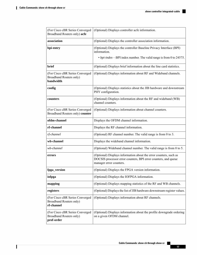
(Optional) Displays controller acfe information.(For Cisco cBR Series ConvergedBroadband Routers only) acfe
(Optional) Displays the controller association information.association
(Optional) Displays the controller Baseline Privacy Interface (BPI)information.
• bpi-index—BPI index number. The valid range is from 0 to 24575.
bpi-entry
(Optional) Displays brief information about the line card statistics.brief
(Optional) Displays information about RF and Wideband channels.(For Cisco cBR Series ConvergedBroadband Routers only)bandwidth
(Optional) Displays statistics about the JIB hardware and downstreamPHY configuration.
config
(Optional) Displays information about the RF and wideband (WB)channel counters.
counters
(Optional) Displays information about channel counters.(For Cisco cBR Series ConvergedBroadband Routers only) counter
Displays the OFDM channel information.ofdm-channel
Displays the RF channel information.rf-channel
(Optional) RF channel number. The valid range is from 0 to 3.rf-channel
Displays the wideband channel information.wb-channel
(Optional) Wideband channel number. The valid range is from 0 to 5.wb-channel
(Optional) Displays information about the error counters, such asDOCSIS processor error counters, BPI error counters, and queuemanager error counters.
errors
(Optional) Displays the FPGA version information.fpga_version
(Optional) Displays the IOFPGA information.iofpga
(Optional) Displays mapping statistics of the RF and WB channels.mapping
(Optional) Displays the list of JIB hardware downstream register values.registers
(Optional) Displays information about RF channels.(For Cisco cBR Series ConvergedBroadband Routers only)rf-channel
(Optional) Displays information about the profile downgrade orderingon a given OFDM channel.
(For Cisco cBR Series ConvergedBroadband Routers only)prof-order
Cable Commands: show ch through show cr17
Cable Commands: show ch through show crshow controller integrated-cable
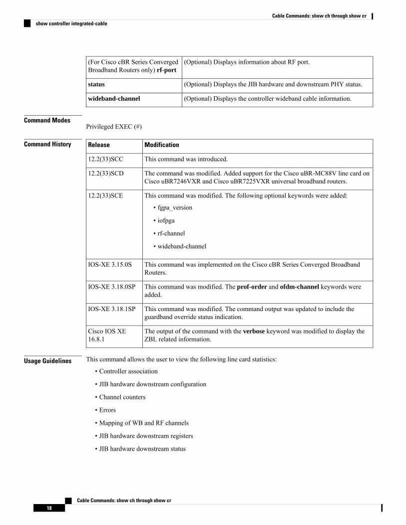
(Optional) Displays information about RF port.(For Cisco cBR Series ConvergedBroadband Routers only) rf-port
(Optional) Displays the JIB hardware and downstream PHY status.status
(Optional) Displays the controller wideband cable information.wideband-channel
Command ModesPrivileged EXEC (#)
Command History ModificationRelease
This command was introduced.12.2(33)SCC
The command was modified. Added support for the Cisco uBR-MC88V line card onCisco uBR7246VXR and Cisco uBR7225VXR universal broadband routers.
12.2(33)SCD
This command was modified. The following optional keywords were added:
• fgpa_version
• iofpga
• rf-channel
• wideband-channel
12.2(33)SCE
This command was implemented on the Cisco cBR Series Converged BroadbandRouters.
IOS-XE 3.15.0S
This command was modified. The prof-order and ofdm-channel keywords wereadded.
IOS-XE 3.18.0SP
This command was modified. The command output was updated to include theguardband override status indication.
IOS-XE 3.18.1SP
The output of the command with the verbose keyword was modified to display theZBL related information.
Cisco IOS XE16.8.1
Usage Guidelines This command allows the user to view the following line card statistics:
• Controller association
• JIB hardware downstream configuration
• Channel counters
• Errors
• Mapping of WB and RF channels
• JIB hardware downstream registers
• JIB hardware downstream status
Cable Commands: show ch through show cr18
Cable Commands: show ch through show crshow controller integrated-cable
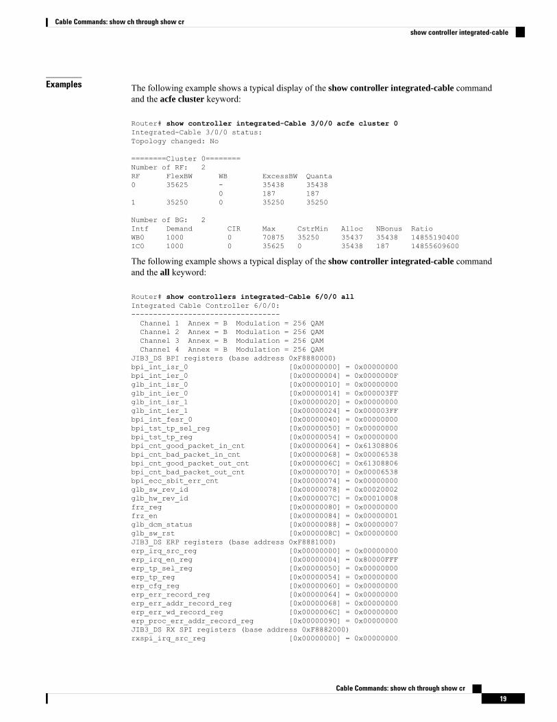
Examples The following example shows a typical display of the show controller integrated-cable commandand the acfe cluster keyword:
Router# show controller integrated-Cable 3/0/0 acfe cluster 0Integrated-Cable 3/0/0 status:Topology changed: No
========Cluster 0========Number of RF: 2RF FlexBW WB ExcessBW Quanta0 35625 - 35438 35438
0 187 1871 35250 0 35250 35250
Number of BG: 2Intf Demand CIR Max CstrMin Alloc NBonus RatioWB0 1000 0 70875 35250 35437 35438 14855190400IC0 1000 0 35625 0 35438 187 14855609600
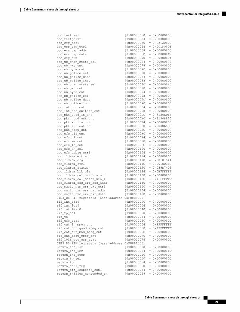
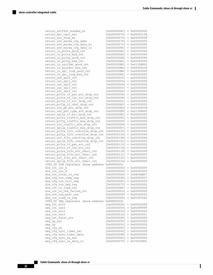
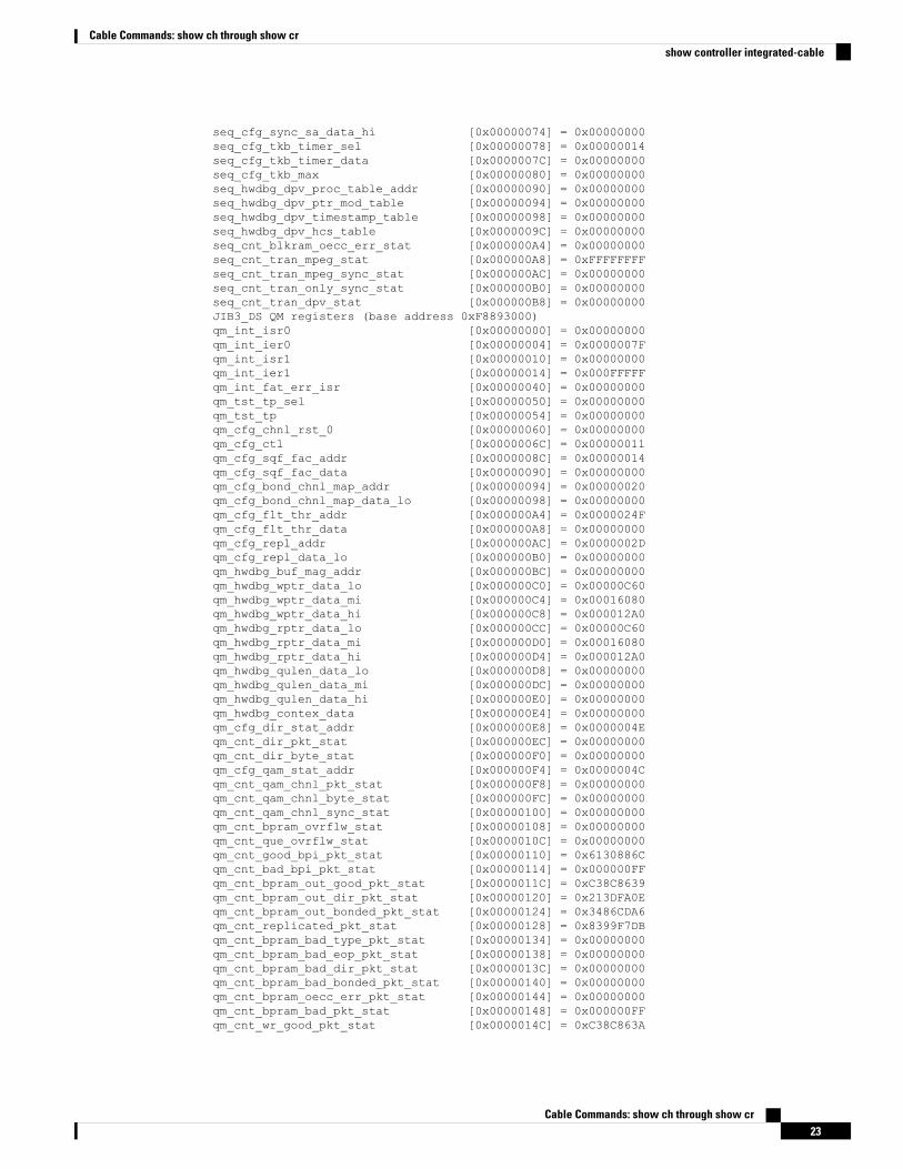
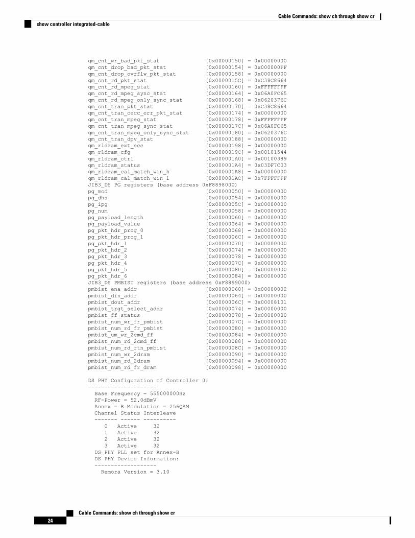
The following example shows a typical display of the show controller integrated-cable commandand the all keyword:
Router# show controllers integrated-Cable 6/0/0 allIntegrated Cable Controller 6/0/0:----------------------------------Channel 1 Annex = B Modulation = 256 QAMChannel 2 Annex = B Modulation = 256 QAMChannel 3 Annex = B Modulation = 256 QAMChannel 4 Annex = B Modulation = 256 QAM
JIB3_DS BPI registers (base address 0xF8880000)bpi_int_isr_0 [0x00000000] = 0x00000000bpi_int_ier_0 [0x00000004] = 0x0000000Fglb_int_isr_0 [0x00000010] = 0x00000000glb_int_ier_0 [0x00000014] = 0x000003FFglb_int_isr_1 [0x00000020] = 0x00000000glb_int_ier_1 [0x00000024] = 0x000003FFbpi_int_fesr_0 [0x00000040] = 0x00000000bpi_tst_tp_sel_reg [0x00000050] = 0x00000000bpi_tst_tp_reg [0x00000054] = 0x00000000bpi_cnt_good_packet_in_cnt [0x00000064] = 0x61308806bpi_cnt_bad_packet_in_cnt [0x00000068] = 0x00006538bpi_cnt_good_packet_out_cnt [0x0000006C] = 0x61308806bpi_cnt_bad_packet_out_cnt [0x00000070] = 0x00006538bpi_ecc_sbit_err_cnt [0x00000074] = 0x00000000glb_sw_rev_id [0x00000078] = 0x00020002glb_hw_rev_id [0x0000007C] = 0x00010008frz_reg [0x00000080] = 0x00000000frz_en [0x00000084] = 0x00000001glb_dcm_status [0x00000088] = 0x00000007glb_sw_rst [0x0000008C] = 0x00000000JIB3_DS ERP registers (base address 0xF8881000)erp_irq_src_reg [0x00000000] = 0x00000000erp_irq_en_reg [0x00000004] = 0x80000FFFerp_tp_sel_reg [0x00000050] = 0x00000000erp_tp_reg [0x00000054] = 0x00000000erp_cfg_reg [0x00000060] = 0x00000000erp_err_record_reg [0x00000064] = 0x00000000erp_err_addr_record_reg [0x00000068] = 0x00000000erp_err_wd_record_reg [0x0000006C] = 0x00000000erp_proc_err_addr_record_reg [0x00000090] = 0x00000000JIB3_DS RX SPI registers (base address 0xF8882000)rxspi_irq_src_reg [0x00000000] = 0x00000000
Cable Commands: show ch through show cr19
Cable Commands: show ch through show crshow controller integrated-cable
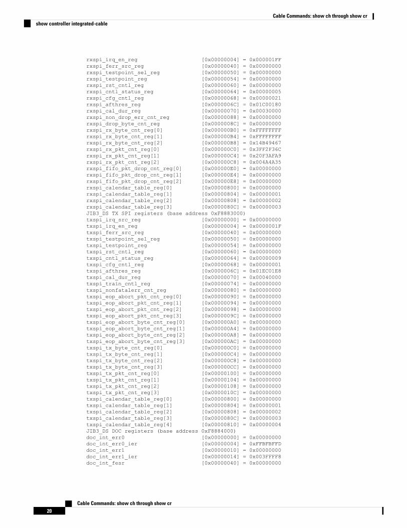
rxspi_irq_en_reg [0x00000004] = 0x000001FFrxspi_ferr_src_reg [0x00000040] = 0x00000000rxspi_testpoint_sel_reg [0x00000050] = 0x00000000rxspi_testpoint_reg [0x00000054] = 0x00000000rxspi_rst_cntl_reg [0x00000060] = 0x00000000rxspi_cntl_status_reg [0x00000064] = 0x00000005rxspi_cfg_cntl_reg [0x00000068] = 0x00000021rxspi_afthres_reg [0x0000006C] = 0x01C00180rxspi_cal_dur_reg [0x00000070] = 0x00030000rxspi_non_drop_err_cnt_reg [0x00000088] = 0x00000000rxspi_drop_byte_cnt_reg [0x0000008C] = 0x00000000rxspi_rx_byte_cnt_reg[0] [0x000000B0] = 0xFFFFFFFFrxspi_rx_byte_cnt_reg[1] [0x000000B4] = 0xFFFFFFFFrxspi_rx_byte_cnt_reg[2] [0x000000B8] = 0x14B49467rxspi_rx_pkt_cnt_reg[0] [0x000000C0] = 0x3FF2F36Crxspi_rx_pkt_cnt_reg[1] [0x000000C4] = 0x20F3AFA9rxspi_rx_pkt_cnt_reg[2] [0x000000C8] = 0x004A4A35rxspi_fifo_pkt_drop_cnt_reg[0] [0x000000E0] = 0x00000000rxspi_fifo_pkt_drop_cnt_reg[1] [0x000000E4] = 0x00000000rxspi_fifo_pkt_drop_cnt_reg[2] [0x000000E8] = 0x00000000rxspi_calendar_table_reg[0] [0x00000800] = 0x00000000rxspi_calendar_table_reg[1] [0x00000804] = 0x00000001rxspi_calendar_table_reg[2] [0x00000808] = 0x00000002rxspi_calendar_table_reg[3] [0x0000080C] = 0x00000003JIB3_DS TX SPI registers (base address 0xF8883000)txspi_irq_src_reg [0x00000000] = 0x00000000txspi_irq_en_reg [0x00000004] = 0x0000001Ftxspi_ferr_src_reg [0x00000040] = 0x00000000txspi_testpoint_sel_reg [0x00000050] = 0x00000000txspi_testpoint_reg [0x00000054] = 0x00000000txspi_rst_cntl_reg [0x00000060] = 0x00000000txspi_cntl_status_reg [0x00000064] = 0x00000009txspi_cfg_cntl_reg [0x00000068] = 0x00000001txspi_afthres_reg [0x0000006C] = 0x01EC01E8txspi_cal_dur_reg [0x00000070] = 0x00040000txspi_train_cntl_reg [0x00000074] = 0x00000000txspi_nonfatalerr_cnt_reg [0x00000080] = 0x00000000txspi_eop_abort_pkt_cnt_reg[0] [0x00000090] = 0x00000000txspi_eop_abort_pkt_cnt_reg[1] [0x00000094] = 0x00000000txspi_eop_abort_pkt_cnt_reg[2] [0x00000098] = 0x00000000txspi_eop_abort_pkt_cnt_reg[3] [0x0000009C] = 0x00000000txspi_eop_abort_byte_cnt_reg[0] [0x000000A0] = 0x00000000txspi_eop_abort_byte_cnt_reg[1] [0x000000A4] = 0x00000000txspi_eop_abort_byte_cnt_reg[2] [0x000000A8] = 0x00000000txspi_eop_abort_byte_cnt_reg[3] [0x000000AC] = 0x00000000txspi_tx_byte_cnt_reg[0] [0x000000C0] = 0x00000000txspi_tx_byte_cnt_reg[1] [0x000000C4] = 0x00000000txspi_tx_byte_cnt_reg[2] [0x000000C8] = 0x00000000txspi_tx_byte_cnt_reg[3] [0x000000CC] = 0x00000000txspi_tx_pkt_cnt_reg[0] [0x00000100] = 0x00000000txspi_tx_pkt_cnt_reg[1] [0x00000104] = 0x00000000txspi_tx_pkt_cnt_reg[2] [0x00000108] = 0x00000000txspi_tx_pkt_cnt_reg[3] [0x0000010C] = 0x00000000txspi_calendar_table_reg[0] [0x00000800] = 0x00000000txspi_calendar_table_reg[1] [0x00000804] = 0x00000001txspi_calendar_table_reg[2] [0x00000808] = 0x00000002txspi_calendar_table_reg[3] [0x0000080C] = 0x00000003txspi_calendar_table_reg[4] [0x00000810] = 0x00000004JIB3_DS DOC registers (base address 0xF8884000)doc_int_err0 [0x00000000] = 0x00000000doc_int_err0_ier [0x00000004] = 0xFFBFBFFDdoc_int_err1 [0x00000010] = 0x00000000doc_int_err1_ier [0x00000014] = 0x003FFFF8doc_int_fesr [0x00000040] = 0x00000000
Cable Commands: show ch through show cr20
Cable Commands: show ch through show crshow controller integrated-cable
doc_test_sel [0x00000050] = 0x00000000doc_testpoint [0x00000054] = 0x00000000doc_cfg_ctrl [0x00000060] = 0x031A0000doc_err_cap_ctrl [0x00000064] = 0x001F0001doc_err_cap_addr [0x00000068] = 0x00000000doc_err_cap_data [0x0000006C] = 0x000080F7doc_seg_num [0x00000070] = 0x00000001doc_wb_chan_stats_sel [0x00000074] = 0x00000077doc_wb_pkt_cnt [0x00000078] = 0x00000000doc_wb_byte_cnt [0x0000007C] = 0x00000000doc_wb_police_sel [0x00000080] = 0x00000000doc_wb_police_data [0x00000084] = 0x00000000doc_wb_police_intv [0x00000088] = 0x00000000doc_nb_chan_stats_sel [0x0000008C] = 0x0000004Cdoc_nb_pkt_cnt [0x00000090] = 0x00000000doc_nb_byte_cnt [0x00000094] = 0x00000000doc_nb_police_sel [0x00000098] = 0x00000000doc_nb_police_data [0x0000009C] = 0x00000000doc_nb_police_intv [0x000000A0] = 0x00000000doc_int_doc_cnt [0x000000D4] = 0x00000000doc_int_ecc_sbiterr_cnt [0x000000D8] = 0x00000000doc_pkt_good_in_cnt [0x000000DC] = 0x6130ED6Fdoc_pkt_good_out_cnt [0x000000E0] = 0x61308837doc_pkt_err_in_cnt [0x000000E4] = 0x00000000doc_pkt_err_out_cnt [0x000000E8] = 0x00006538doc_pkt_drop_cnt [0x000000EC] = 0x00000000doc_efc_all_cnt [0x000000F0] = 0x00000000doc_efc_hi_cnt [0x000000F4] = 0x00000000doc_efc_me_cnt [0x000000F8] = 0x00000000doc_efc_lo_cnt [0x000000FC] = 0x00000000doc_efc_ch_sel [0x00000100] = 0x00000000doc_efc_debug_ctrl [0x00000104] = 0x00000000doc_rldram_ext_ecc [0x00000114] = 0x00000000doc_rldram_cfg [0x00000118] = 0x00101544doc_rldram_ctrl [0x0000011C] = 0x00100389doc_rldram_status [0x00000120] = 0x039D7403doc_rldram_blk_clr [0x00000124] = 0x0B7FFFFFdoc_rldram_cal_match_win_h [0x00000128] = 0x00000000doc_rldram_cal_match_win_l [0x0000012C] = 0x1FFFFFFFdoc_rldram_ecc_err_rec_addr [0x00000130] = 0x00000000doc_magic_num_err_pkt_ctrl [0x00000150] = 0x00000000doc_magic_num_err_pkt_addr [0x00000154] = 0x00000000doc_magic_num_err_pkt_data [0x00000158] = 0x00000000JIB3_DS RIF registers (base address 0xF8885000)rif_int_err0 [0x00000000] = 0x00000000rif_int_ier0 [0x00000004] = 0x00000007rif_int_fesr0 [0x00000040] = 0x00000000rif_tp_sel [0x00000050] = 0x00000000rif_tp [0x00000054] = 0x00000000rif_cfg_ctrl [0x00000060] = 0x00000000rif_cnt_in_mpeg_cnt [0x00000064] = 0xFFFFFFFFrif_cnt_out_good_mpeg_cnt [0x00000068] = 0xFFFFFFFFrif_cnt_out_bad_mpeg_cnt [0x0000006C] = 0x00000000rif_cnt_drop_mpeg_cnt [0x00000070] = 0x00000000rif_1bit_ecc_err_stat [0x00000074] = 0x00000000JIB3_DS RTN registers (base address 0xF8886000)return_int_isr [0x00000000] = 0x00000000return_int_ier [0x00000004] = 0x000001FFreturn_int_fesr [0x00000040] = 0x00000000return_tp_sel [0x00000050] = 0x00000000return_tp [0x00000054] = 0x00000000return_ctrl_reg [0x00000060] = 0x00000000return_pif_loopback_chnl [0x00000064] = 0x00000000return_sniffer_nonbonded_en [0x00000068] = 0x00000000
Cable Commands: show ch through show cr21
Cable Commands: show ch through show crshow controller integrated-cable
return_sniffer_bonded_en [0x0000006C] = 0x00000000return_spi_chnl_sel [0x00000070] = 0x0000013Areturn_err_drop_en [0x00000074] = 0x0000000Freturn_snf_macda_cfg_addr [0x00000078] = 0x00000000return_snf_macda_cfg_data_hi [0x0000007C] = 0x00000000return_snf_macda_cfg_data_lo [0x00000080] = 0x00000000return_in_pifrx_good_cnt [0x000000A0] = 0x00000000return_in_pifrx_bad_cnt [0x000000A4] = 0x00000000return_in_piflp_good_cnt [0x000000A8] = 0xFFFFFFFFreturn_in_piflp_bad_cnt [0x000000AC] = 0x00000000return_in_sniffer_good_cnt [0x000000B0] = 0x61308845return_in_sniffer_bad_cnt [0x000000B4] = 0x00006538return_in_spi_loop_good_cnt [0x000000B8] = 0x00000000return_in_spi_loop_bad_cnt [0x000000BC] = 0x00000000return_out_spi0_cnt [0x000000C0] = 0x00000000return_out_spi1_cnt [0x000000C4] = 0x00000000return_out_spi2_cnt [0x000000C8] = 0x00000000return_out_spi3_cnt [0x000000CC] = 0x00000000return_out_spi4_cnt [0x000000D0] = 0x00000000return_pifrx_if_par_err_drop_cnt [0x000000D4] = 0x00000000return_pifrx_if_len_err_drop_cnt [0x000000D8] = 0x00000000return_piflp_if_err_drop_cnt [0x000000DC] = 0x00000000return_piflp_if_chnl_drop_cnt [0x000000E0] = 0x00000000return_snf_pb_err_drop_cnt [0x000000E4] = 0x00006538return_snf_pkt_type_err_drop_cnt [0x000000E8] = 0x61308845return_spilp_if_err_drop_cnt [0x000000EC] = 0x00000000return_pifrx_traffic_mux_drop_cnt [0x000000F0] = 0x00000000return_piflp_traffic_mux_drop_cnt [0x000000F4] = 0x00000000return_snf_traffic_mux_drop_cnt [0x000000F8] = 0x00000000return_spilp_traffic_mux_drop_cnt [0x000000FC] = 0x00000000return_pifrx_fifo_overflow_drop_cnt [0x00000100] = 0x00000000return_piflp_fifo_overflow_drop_cnt [0x00000104] = 0x00000000return_snf_fifo_overflow_drop_cnt [0x00000108] = 0x00000000return_spilp_fifo_overflow_drop_cnt [0x0000010C] = 0x00000000return_pifrx_if_par_err_cnt [0x00000110] = 0x00000000return_pifrx_if_len_err_cnt [0x00000114] = 0x00000000return_pifrx_fifo_ecc_1berr_cnt [0x00000118] = 0x00000000return_piflp_fifo_ecc_1berr_cnt [0x0000011C] = 0x00000000return_snf_fifo_ecc_1berr_cnt [0x00000120] = 0x00000000return_spilp_fifo_ecc_1berr_cnt [0x00000124] = 0x00000000JIB3_DS DLM registers (base address 0xF8890000)dlm_int_isr_0 [0x00000000] = 0x00000005dlm_int_ier_0 [0x00000004] = 0x00000000dlm_cnt_local_ts_reg [0x00000064] = 0x5B00EB07dlm_cfg_tss_comp_reg [0x00000068] = 0x00000027dlm_cfg_tss_ctrl_reg [0x0000006C] = 0x00000000dlm_cfg_tss_cmd_reg [0x00000070] = 0x00000000dlm_cnt_ts_load_cnt [0x000000BC] = 0x00000000dlm_cnt_ts_chk_failed_cnt [0x000000C4] = 0x00000000dlm_cnt_tss_perr_cnt [0x000000C8] = 0x00000000dlm_cnt_load_ts_reg [0x000000D0] = 0x003F52EFJIB3_DS SEQ registers (base address 0xF8892000)seq_int_err0 [0x00000000] = 0x0000000Fseq_int_ier0 [0x00000004] = 0x000FFFFFseq_int_err3 [0x00000030] = 0x00000000seq_int_ier3 [0x00000034] = 0x00000001seq_int_fatal_err [0x00000040] = 0x00000000seq_tp_sel [0x00000050] = 0x00000000seq_tp [0x00000054] = 0x00000000seq_cfg_en [0x00000060] = 0x00000001seq_cfg_sync_timer_sel [0x00000064] = 0x00000004seq_cfg_sync_timer_data [0x00000068] = 0x00000000seq_cfg_sync_sa_sel [0x0000006C] = 0x00000004seq_cfg_sync_sa_data_lo [0x00000070] = 0x70CC0B91
Cable Commands: show ch through show cr22
Cable Commands: show ch through show crshow controller integrated-cable
seq_cfg_sync_sa_data_hi [0x00000074] = 0x00000000seq_cfg_tkb_timer_sel [0x00000078] = 0x00000014seq_cfg_tkb_timer_data [0x0000007C] = 0x00000000seq_cfg_tkb_max [0x00000080] = 0x00000000seq_hwdbg_dpv_proc_table_addr [0x00000090] = 0x00000000seq_hwdbg_dpv_ptr_mod_table [0x00000094] = 0x00000000seq_hwdbg_dpv_timestamp_table [0x00000098] = 0x00000000seq_hwdbg_dpv_hcs_table [0x0000009C] = 0x00000000seq_cnt_blkram_oecc_err_stat [0x000000A4] = 0x00000000seq_cnt_tran_mpeg_stat [0x000000A8] = 0xFFFFFFFFseq_cnt_tran_mpeg_sync_stat [0x000000AC] = 0x00000000seq_cnt_tran_only_sync_stat [0x000000B0] = 0x00000000seq_cnt_tran_dpv_stat [0x000000B8] = 0x00000000JIB3_DS QM registers (base address 0xF8893000)qm_int_isr0 [0x00000000] = 0x00000000qm_int_ier0 [0x00000004] = 0x0000007Fqm_int_isr1 [0x00000010] = 0x00000000qm_int_ier1 [0x00000014] = 0x000FFFFFqm_int_fat_err_isr [0x00000040] = 0x00000000qm_tst_tp_sel [0x00000050] = 0x00000000qm_tst_tp [0x00000054] = 0x00000000qm_cfg_chnl_rst_0 [0x00000060] = 0x00000000qm_cfg_ctl [0x0000006C] = 0x00000011qm_cfg_sqf_fac_addr [0x0000008C] = 0x00000014qm_cfg_sqf_fac_data [0x00000090] = 0x00000000qm_cfg_bond_chnl_map_addr [0x00000094] = 0x00000020qm_cfg_bond_chnl_map_data_lo [0x00000098] = 0x00000000qm_cfg_flt_thr_addr [0x000000A4] = 0x0000024Fqm_cfg_flt_thr_data [0x000000A8] = 0x00000000qm_cfg_repl_addr [0x000000AC] = 0x0000002Dqm_cfg_repl_data_lo [0x000000B0] = 0x00000000qm_hwdbg_buf_mag_addr [0x000000BC] = 0x00000000qm_hwdbg_wptr_data_lo [0x000000C0] = 0x00000C60qm_hwdbg_wptr_data_mi [0x000000C4] = 0x00016080qm_hwdbg_wptr_data_hi [0x000000C8] = 0x000012A0qm_hwdbg_rptr_data_lo [0x000000CC] = 0x00000C60qm_hwdbg_rptr_data_mi [0x000000D0] = 0x00016080qm_hwdbg_rptr_data_hi [0x000000D4] = 0x000012A0qm_hwdbg_qulen_data_lo [0x000000D8] = 0x00000000qm_hwdbg_qulen_data_mi [0x000000DC] = 0x00000000qm_hwdbg_qulen_data_hi [0x000000E0] = 0x00000000qm_hwdbg_contex_data [0x000000E4] = 0x00000000qm_cfg_dir_stat_addr [0x000000E8] = 0x0000004Eqm_cnt_dir_pkt_stat [0x000000EC] = 0x00000000qm_cnt_dir_byte_stat [0x000000F0] = 0x00000000qm_cfg_qam_stat_addr [0x000000F4] = 0x0000004Cqm_cnt_qam_chnl_pkt_stat [0x000000F8] = 0x00000000qm_cnt_qam_chnl_byte_stat [0x000000FC] = 0x00000000qm_cnt_qam_chnl_sync_stat [0x00000100] = 0x00000000qm_cnt_bpram_ovrflw_stat [0x00000108] = 0x00000000qm_cnt_que_ovrflw_stat [0x0000010C] = 0x00000000qm_cnt_good_bpi_pkt_stat [0x00000110] = 0x6130886Cqm_cnt_bad_bpi_pkt_stat [0x00000114] = 0x000000FFqm_cnt_bpram_out_good_pkt_stat [0x0000011C] = 0xC38C8639qm_cnt_bpram_out_dir_pkt_stat [0x00000120] = 0x213DFA0Eqm_cnt_bpram_out_bonded_pkt_stat [0x00000124] = 0x3486CDA6qm_cnt_replicated_pkt_stat [0x00000128] = 0x8399F7DBqm_cnt_bpram_bad_type_pkt_stat [0x00000134] = 0x00000000qm_cnt_bpram_bad_eop_pkt_stat [0x00000138] = 0x00000000qm_cnt_bpram_bad_dir_pkt_stat [0x0000013C] = 0x00000000qm_cnt_bpram_bad_bonded_pkt_stat [0x00000140] = 0x00000000qm_cnt_bpram_oecc_err_pkt_stat [0x00000144] = 0x00000000qm_cnt_bpram_bad_pkt_stat [0x00000148] = 0x000000FFqm_cnt_wr_good_pkt_stat [0x0000014C] = 0xC38C863A
Cable Commands: show ch through show cr23
Cable Commands: show ch through show crshow controller integrated-cable
qm_cnt_wr_bad_pkt_stat [0x00000150] = 0x00000000qm_cnt_drop_bad_pkt_stat [0x00000154] = 0x000000FFqm_cnt_drop_ovrflw_pkt_stat [0x00000158] = 0x00000000qm_cnt_rd_pkt_stat [0x0000015C] = 0xC38C8664qm_cnt_rd_mpeg_stat [0x00000160] = 0xFFFFFFFFqm_cnt_rd_mpeg_sync_stat [0x00000164] = 0x06A0FC65qm_cnt_rd_mpeg_only_sync_stat [0x00000168] = 0x0620376Cqm_cnt_tran_pkt_stat [0x00000170] = 0xC38C8664qm_cnt_tran_oecc_err_pkt_stat [0x00000174] = 0x00000000qm_cnt_tran_mpeg_stat [0x00000178] = 0xFFFFFFFFqm_cnt_tran_mpeg_sync_stat [0x0000017C] = 0x06A0FC65qm_cnt_tran_mpeg_only_sync_stat [0x00000180] = 0x0620376Cqm_cnt_tran_dpv_stat [0x00000188] = 0x00000000qm_rldram_ext_ecc [0x00000198] = 0x00000000qm_rldram_cfg [0x0000019C] = 0x00101544qm_rldram_ctrl [0x000001A0] = 0x00100389qm_rldram_status [0x000001A4] = 0x03DF7C03qm_rldram_cal_match_win_h [0x000001A8] = 0x00000000qm_rldram_cal_match_win_l [0x000001AC] = 0x7FFFFFFFJIB3_DS PG registers (base address 0xF8898000)pg_mod [0x00000050] = 0x00000000pg_dhs [0x00000054] = 0x00000000pg_ipg [0x0000005C] = 0x00000000pg_num [0x00000058] = 0x00000000pg_payload_length [0x00000060] = 0x00000000pg_payload_value [0x00000064] = 0x00000000pg_pkt_hdr_prog_0 [0x00000068] = 0x00000000pg_pkt_hdr_prog_1 [0x0000006C] = 0x00000000pg_pkt_hdr_1 [0x00000070] = 0x00000000pg_pkt_hdr_2 [0x00000074] = 0x00000000pg_pkt_hdr_3 [0x00000078] = 0x00000000pg_pkt_hdr_4 [0x0000007C] = 0x00000000pg_pkt_hdr_5 [0x00000080] = 0x00000000pg_pkt_hdr_6 [0x00000084] = 0x00000000JIB3_DS PMBIST registers (base address 0xF8899000)pmbist_ena_addr [0x00000060] = 0x00000002pmbist_din_addr [0x00000064] = 0x00000000pmbist_dout_addr [0x0000006C] = 0x00008101pmbist_trgt_select_addr [0x00000074] = 0x00000000pmbist_ff_status [0x00000078] = 0x00000000pmbist_num_wr_fr_pmbist [0x0000007C] = 0x00000000pmbist_num_rd_fr_pmbist [0x00000080] = 0x00000000pmbist_um_wr_2cmd_ff [0x00000084] = 0x00000000pmbist_num_rd_2cmd_ff [0x00000088] = 0x00000000pmbist_num_rd_rtn_pmbist [0x0000008C] = 0x00000000pmbist_num_wr_2dram [0x00000090] = 0x00000000pmbist_num_rd_2dram [0x00000094] = 0x00000000pmbist_num_rd_fr_dram [0x00000098] = 0x00000000
DS PHY Configuration of Controller 0:---------------------Base Frequency = 555000000HzRF-Power = 52.0dBmVAnnex = B Modulation = 256QAMChannel Status Interleave------- ------ ----------
0 Active 321 Active 322 Active 323 Active 32
DS_PHY PLL set for Annex-BDS PHY Device Information:-------------------Remora Version = 3.10
Cable Commands: show ch through show cr24
Cable Commands: show ch through show crshow controller integrated-cable
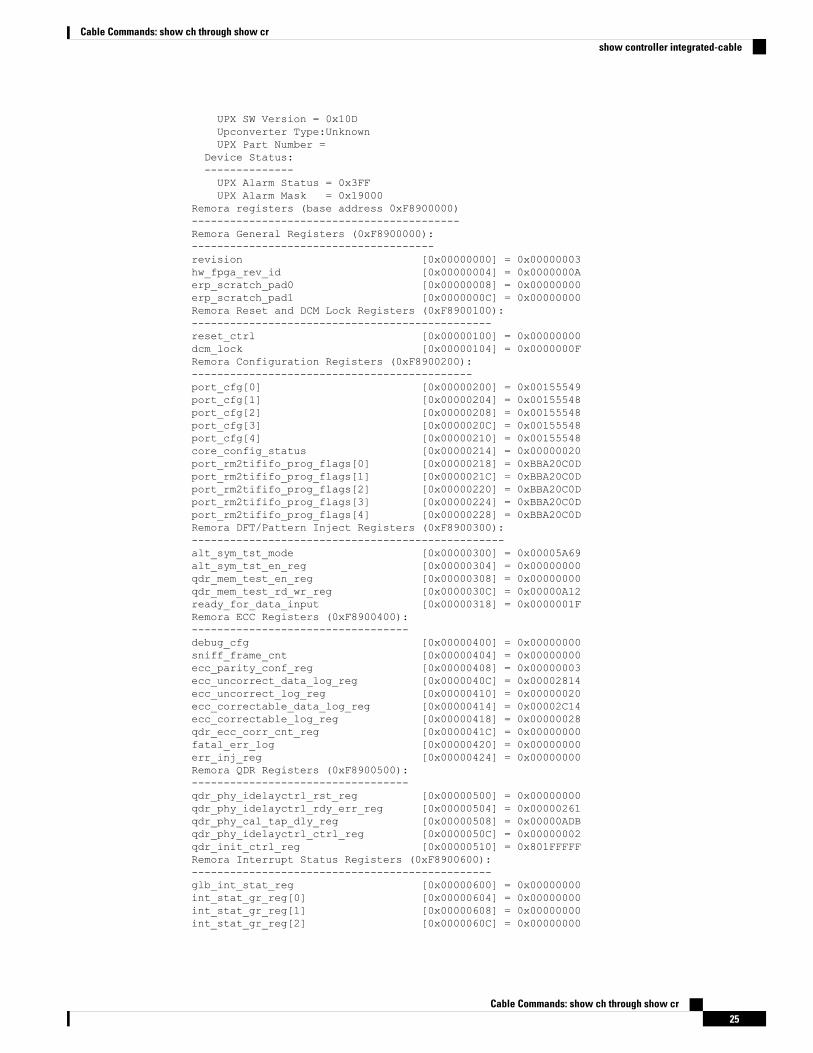
UPX SW Version = 0x10DUpconverter Type:UnknownUPX Part Number =
Device Status:--------------UPX Alarm Status = 0x3FFUPX Alarm Mask = 0x19000
Remora registers (base address 0xF8900000)------------------------------------------Remora General Registers (0xF8900000):--------------------------------------revision [0x00000000] = 0x00000003hw_fpga_rev_id [0x00000004] = 0x0000000Aerp_scratch_pad0 [0x00000008] = 0x00000000erp_scratch_pad1 [0x0000000C] = 0x00000000Remora Reset and DCM Lock Registers (0xF8900100):-----------------------------------------------reset_ctrl [0x00000100] = 0x00000000dcm_lock [0x00000104] = 0x0000000FRemora Configuration Registers (0xF8900200):--------------------------------------------port_cfg[0] [0x00000200] = 0x00155549port_cfg[1] [0x00000204] = 0x00155548port_cfg[2] [0x00000208] = 0x00155548port_cfg[3] [0x0000020C] = 0x00155548port_cfg[4] [0x00000210] = 0x00155548core_config_status [0x00000214] = 0x00000020port_rm2tififo_prog_flags[0] [0x00000218] = 0xBBA20C0Dport_rm2tififo_prog_flags[1] [0x0000021C] = 0xBBA20C0Dport_rm2tififo_prog_flags[2] [0x00000220] = 0xBBA20C0Dport_rm2tififo_prog_flags[3] [0x00000224] = 0xBBA20C0Dport_rm2tififo_prog_flags[4] [0x00000228] = 0xBBA20C0DRemora DFT/Pattern Inject Registers (0xF8900300):-------------------------------------------------alt_sym_tst_mode [0x00000300] = 0x00005A69alt_sym_tst_en_reg [0x00000304] = 0x00000000qdr_mem_test_en_reg [0x00000308] = 0x00000000qdr_mem_test_rd_wr_reg [0x0000030C] = 0x00000A12ready_for_data_input [0x00000318] = 0x0000001FRemora ECC Registers (0xF8900400):----------------------------------debug_cfg [0x00000400] = 0x00000000sniff_frame_cnt [0x00000404] = 0x00000000ecc_parity_conf_reg [0x00000408] = 0x00000003ecc_uncorrect_data_log_reg [0x0000040C] = 0x00002814ecc_uncorrect_log_reg [0x00000410] = 0x00000020ecc_correctable_data_log_reg [0x00000414] = 0x00002C14ecc_correctable_log_reg [0x00000418] = 0x00000028qdr_ecc_corr_cnt_reg [0x0000041C] = 0x00000000fatal_err_log [0x00000420] = 0x00000000err_inj_reg [0x00000424] = 0x00000000Remora QDR Registers (0xF8900500):----------------------------------qdr_phy_idelayctrl_rst_reg [0x00000500] = 0x00000000qdr_phy_idelayctrl_rdy_err_reg [0x00000504] = 0x00000261qdr_phy_cal_tap_dly_reg [0x00000508] = 0x00000ADBqdr_phy_idelayctrl_ctrl_reg [0x0000050C] = 0x00000002qdr_init_ctrl_reg [0x00000510] = 0x801FFFFFRemora Interrupt Status Registers (0xF8900600):-----------------------------------------------glb_int_stat_reg [0x00000600] = 0x00000000int_stat_gr_reg[0] [0x00000604] = 0x00000000int_stat_gr_reg[1] [0x00000608] = 0x00000000int_stat_gr_reg[2] [0x0000060C] = 0x00000000
Cable Commands: show ch through show cr25
Cable Commands: show ch through show crshow controller integrated-cable
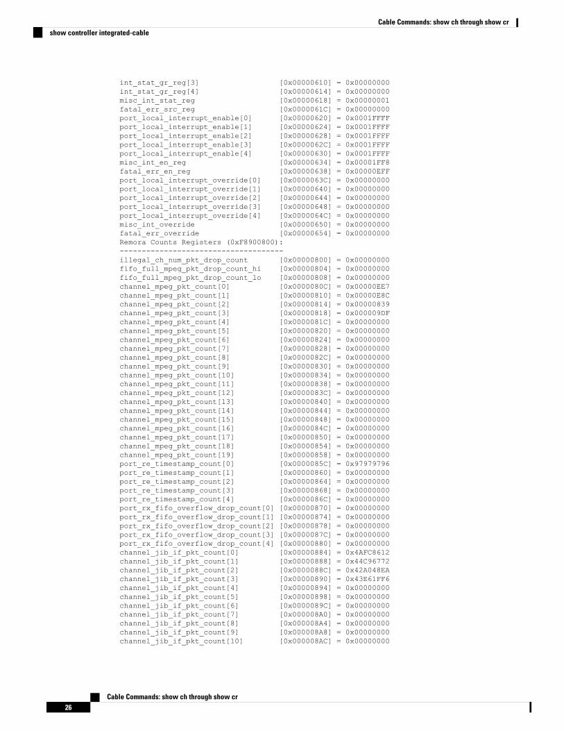
int_stat_gr_reg[3] [0x00000610] = 0x00000000int_stat_gr_reg[4] [0x00000614] = 0x00000000misc_int_stat_reg [0x00000618] = 0x00000001fatal_err_src_reg [0x0000061C] = 0x00000000port_local_interrupt_enable[0] [0x00000620] = 0x0001FFFFport_local_interrupt_enable[1] [0x00000624] = 0x0001FFFFport_local_interrupt_enable[2] [0x00000628] = 0x0001FFFFport_local_interrupt_enable[3] [0x0000062C] = 0x0001FFFFport_local_interrupt_enable[4] [0x00000630] = 0x0001FFFFmisc_int_en_reg [0x00000634] = 0x00001FF8fatal_err_en_reg [0x00000638] = 0x00000EFFport_local_interrupt_override[0] [0x0000063C] = 0x00000000port_local_interrupt_override[1] [0x00000640] = 0x00000000port_local_interrupt_override[2] [0x00000644] = 0x00000000port_local_interrupt_override[3] [0x00000648] = 0x00000000port_local_interrupt_override[4] [0x0000064C] = 0x00000000misc_int_override [0x00000650] = 0x00000000fatal_err_override [0x00000654] = 0x00000000Remora Counts Registers (0xF8900800):-------------------------------------illegal_ch_num_pkt_drop_count [0x00000800] = 0x00000000fifo_full_mpeg_pkt_drop_count_hi [0x00000804] = 0x00000000fifo_full_mpeg_pkt_drop_count_lo [0x00000808] = 0x00000000channel_mpeg_pkt_count[0] [0x0000080C] = 0x00000EE7channel_mpeg_pkt_count[1] [0x00000810] = 0x00000E8Cchannel_mpeg_pkt_count[2] [0x00000814] = 0x00000839channel_mpeg_pkt_count[3] [0x00000818] = 0x000009DFchannel_mpeg_pkt_count[4] [0x0000081C] = 0x00000000channel_mpeg_pkt_count[5] [0x00000820] = 0x00000000channel_mpeg_pkt_count[6] [0x00000824] = 0x00000000channel_mpeg_pkt_count[7] [0x00000828] = 0x00000000channel_mpeg_pkt_count[8] [0x0000082C] = 0x00000000channel_mpeg_pkt_count[9] [0x00000830] = 0x00000000channel_mpeg_pkt_count[10] [0x00000834] = 0x00000000channel_mpeg_pkt_count[11] [0x00000838] = 0x00000000channel_mpeg_pkt_count[12] [0x0000083C] = 0x00000000channel_mpeg_pkt_count[13] [0x00000840] = 0x00000000channel_mpeg_pkt_count[14] [0x00000844] = 0x00000000channel_mpeg_pkt_count[15] [0x00000848] = 0x00000000channel_mpeg_pkt_count[16] [0x0000084C] = 0x00000000channel_mpeg_pkt_count[17] [0x00000850] = 0x00000000channel_mpeg_pkt_count[18] [0x00000854] = 0x00000000channel_mpeg_pkt_count[19] [0x00000858] = 0x00000000port_re_timestamp_count[0] [0x0000085C] = 0x97979796port_re_timestamp_count[1] [0x00000860] = 0x00000000port_re_timestamp_count[2] [0x00000864] = 0x00000000port_re_timestamp_count[3] [0x00000868] = 0x00000000port_re_timestamp_count[4] [0x0000086C] = 0x00000000port_rx_fifo_overflow_drop_count[0] [0x00000870] = 0x00000000port_rx_fifo_overflow_drop_count[1] [0x00000874] = 0x00000000port_rx_fifo_overflow_drop_count[2] [0x00000878] = 0x00000000port_rx_fifo_overflow_drop_count[3] [0x0000087C] = 0x00000000port_rx_fifo_overflow_drop_count[4] [0x00000880] = 0x00000000channel_jib_if_pkt_count[0] [0x00000884] = 0x4AFC8612channel_jib_if_pkt_count[1] [0x00000888] = 0x44C96772channel_jib_if_pkt_count[2] [0x0000088C] = 0x42A048EAchannel_jib_if_pkt_count[3] [0x00000890] = 0x43E61FF6channel_jib_if_pkt_count[4] [0x00000894] = 0x00000000channel_jib_if_pkt_count[5] [0x00000898] = 0x00000000channel_jib_if_pkt_count[6] [0x0000089C] = 0x00000000channel_jib_if_pkt_count[7] [0x000008A0] = 0x00000000channel_jib_if_pkt_count[8] [0x000008A4] = 0x00000000channel_jib_if_pkt_count[9] [0x000008A8] = 0x00000000channel_jib_if_pkt_count[10] [0x000008AC] = 0x00000000
Cable Commands: show ch through show cr26
Cable Commands: show ch through show crshow controller integrated-cable
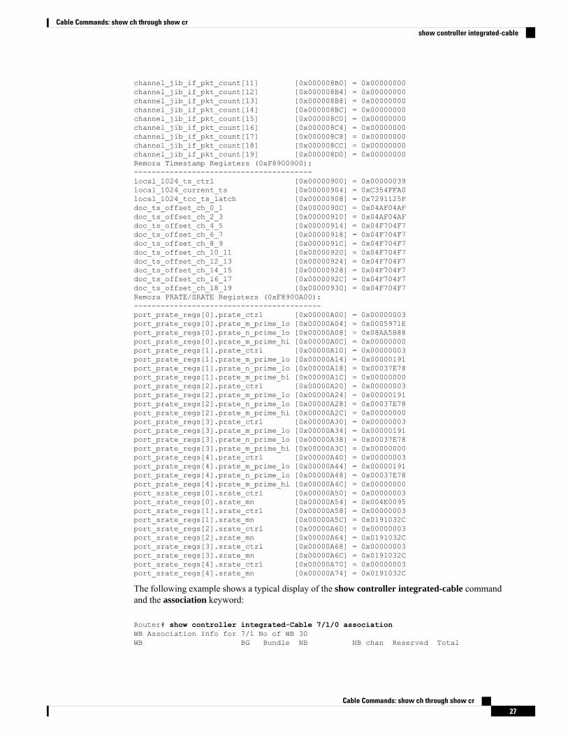
channel_jib_if_pkt_count[11] [0x000008B0] = 0x00000000channel_jib_if_pkt_count[12] [0x000008B4] = 0x00000000channel_jib_if_pkt_count[13] [0x000008B8] = 0x00000000channel_jib_if_pkt_count[14] [0x000008BC] = 0x00000000channel_jib_if_pkt_count[15] [0x000008C0] = 0x00000000channel_jib_if_pkt_count[16] [0x000008C4] = 0x00000000channel_jib_if_pkt_count[17] [0x000008C8] = 0x00000000channel_jib_if_pkt_count[18] [0x000008CC] = 0x00000000channel_jib_if_pkt_count[19] [0x000008D0] = 0x00000000Remora Timestamp Registers (0xF8900900):----------------------------------------local_1024_ts_ctrl [0x00000900] = 0x00000039local_1024_current_ts [0x00000904] = 0xC354FFA0local_1024_tcc_ts_latch [0x00000908] = 0x7291125Fdoc_ts_offset_ch_0_1 [0x0000090C] = 0x04AF04AFdoc_ts_offset_ch_2_3 [0x00000910] = 0x04AF04AFdoc_ts_offset_ch_4_5 [0x00000914] = 0x04F704F7doc_ts_offset_ch_6_7 [0x00000918] = 0x04F704F7doc_ts_offset_ch_8_9 [0x0000091C] = 0x04F704F7doc_ts_offset_ch_10_11 [0x00000920] = 0x04F704F7doc_ts_offset_ch_12_13 [0x00000924] = 0x04F704F7doc_ts_offset_ch_14_15 [0x00000928] = 0x04F704F7doc_ts_offset_ch_16_17 [0x0000092C] = 0x04F704F7doc_ts_offset_ch_18_19 [0x00000930] = 0x04F704F7Remora PRATE/SRATE Registers (0xF8900A00):------------------------------------------port_prate_regs[0].prate_ctrl [0x00000A00] = 0x00000003port_prate_regs[0].prate_m_prime_lo [0x00000A04] = 0x0005971Eport_prate_regs[0].prate_n_prime_lo [0x00000A08] = 0x08AA5B88port_prate_regs[0].prate_m_prime_hi [0x00000A0C] = 0x00000000port_prate_regs[1].prate_ctrl [0x00000A10] = 0x00000003port_prate_regs[1].prate_m_prime_lo [0x00000A14] = 0x00000191port_prate_regs[1].prate_n_prime_lo [0x00000A18] = 0x00037E78port_prate_regs[1].prate_m_prime_hi [0x00000A1C] = 0x00000000port_prate_regs[2].prate_ctrl [0x00000A20] = 0x00000003port_prate_regs[2].prate_m_prime_lo [0x00000A24] = 0x00000191port_prate_regs[2].prate_n_prime_lo [0x00000A28] = 0x00037E78port_prate_regs[2].prate_m_prime_hi [0x00000A2C] = 0x00000000port_prate_regs[3].prate_ctrl [0x00000A30] = 0x00000003port_prate_regs[3].prate_m_prime_lo [0x00000A34] = 0x00000191port_prate_regs[3].prate_n_prime_lo [0x00000A38] = 0x00037E78port_prate_regs[3].prate_m_prime_hi [0x00000A3C] = 0x00000000port_prate_regs[4].prate_ctrl [0x00000A40] = 0x00000003port_prate_regs[4].prate_m_prime_lo [0x00000A44] = 0x00000191port_prate_regs[4].prate_n_prime_lo [0x00000A48] = 0x00037E78port_prate_regs[4].prate_m_prime_hi [0x00000A4C] = 0x00000000port_srate_regs[0].srate_ctrl [0x00000A50] = 0x00000003port_srate_regs[0].srate_mn [0x00000A54] = 0x004E0095port_srate_regs[1].srate_ctrl [0x00000A58] = 0x00000003port_srate_regs[1].srate_mn [0x00000A5C] = 0x0191032Cport_srate_regs[2].srate_ctrl [0x00000A60] = 0x00000003port_srate_regs[2].srate_mn [0x00000A64] = 0x0191032Cport_srate_regs[3].srate_ctrl [0x00000A68] = 0x00000003port_srate_regs[3].srate_mn [0x00000A6C] = 0x0191032Cport_srate_regs[4].srate_ctrl [0x00000A70] = 0x00000003port_srate_regs[4].srate_mn [0x00000A74] = 0x0191032C
The following example shows a typical display of the show controller integrated-cable commandand the association keyword:
Router# show controller integrated-Cable 7/1/0 associationWB Association Info for 7/1 No of WB 30WB BG Bundle NB NB chan Reserved Total
Cable Commands: show ch through show cr27
Cable Commands: show ch through show crshow controller integrated-cable
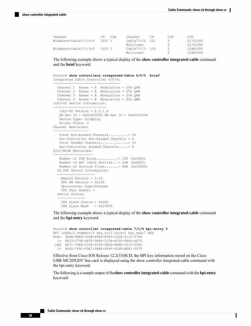
channel ID num channel ID CIR CIRWideband-Cable7/1/0:0 1057 1 Cable7/1/0 121 0 21751500
Multicast 0 21751500Wideband-Cable7/1/3:0 1153 1 Cable7/1/3 133 0 12481000
Multicast 0 12481000
The following example shows a typical display of the show controller integrated-cable commandand the brief keyword:
Router# show controllers integrated-Cable 6/0/0 briefIntegrated Cable Controller 6/0/0:----------------------------------Channel 1 Annex = B Modulation = 256 QAMChannel 2 Annex = B Modulation = 256 QAMChannel 3 Annex = B Modulation = 256 QAMChannel 4 Annex = B Modulation = 256 QAM
Jib3-DS Device Information:---------------------------
Jib3-DS Version = 2.2.1.8SW Rev ID = 0x00020002 HW Rev ID = 0x00010008Device Type: ColdplayDriver State: 3
Channel Resources:------------------
Total Non-bonded Channels..........= 20Per-Controller Non-bonded Channels = 4Total Bonded Channels..............= 32Per-Controller Bonded Channels.....= 6
Slot-Wide Resources:--------------------
Number of PHS Rules...........= 12K (0x3000)Number of BPI Table Entries...= 24K (0x6000)Number of Service Flows.......= 64K (0x10000)DS PHY Device Information:-------------------Remora Version = 3.10UPX SW Version = 0x10DUpconverter Type:UnknownUPX Part Number =
Device Status:--------------UPX Alarm Status = 0x3FFUPX Alarm Mask = 0x19000
The following example shows a typical display of the show controller integrated-cable commandand the bpi-entry keyword:
Router# show controller integrated-cable 7/1/4 bpi-entry 3BPI index:3 segment:0 key_no:3 said:2 key_seq:7 AESEven 5A4B-68E8-5948-FD84-F5E2-1D28-311C-37D8Iv 4E33-379E-6FCF-9A8E-01CB-AC95-5B4D-AE76Odd A871-76EA-1D3E-02F8-5EDA-8A8E-1F15-52E6Iv 6F62-765C-C9E7-DB8A-6FA5-91E8-BE41-3075
Effective from Cisco IOS Release 12.2(33)SCD, the BPI key information stored on the CiscoUBR-MC20X20V line card is displayed using the show controller integrated-cable command withthe bpi-entry keyword.
The following is a sample output of theshow controller integrated-cable commandwith the bpi-entrykeyword:
Cable Commands: show ch through show cr28
Cable Commands: show ch through show crshow controller integrated-cable
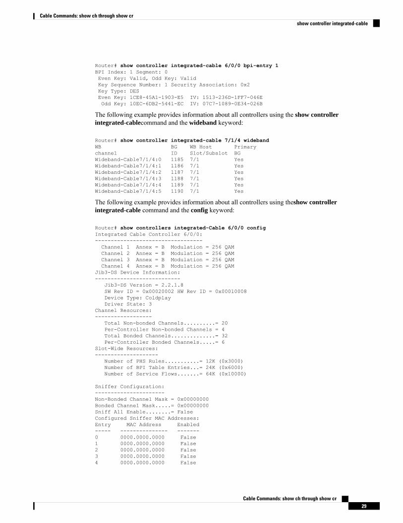
Router# show controller integrated-cable 6/0/0 bpi-entry 1BPI Index: 1 Segment: 0Even Key: Valid, Odd Key: ValidKey Sequence Number: 1 Security Association: 0x2Key Type: DESEven Key: 1CE8-45A1-1903-E5 IV: 1513-236D-1FF7-046EOdd Key: 10EC-6DB2-5441-EC IV: 07C7-1089-0E34-026B
The following example provides information about all controllers using the show controllerintegrated-cablecommand and the wideband keyword:
Router# show controller integrated-cable 7/1/4 widebandWB BG WB Host Primarychannel ID Slot/Subslot BGWideband-Cable7/1/4:0 1185 7/1 YesWideband-Cable7/1/4:1 1186 7/1 YesWideband-Cable7/1/4:2 1187 7/1 YesWideband-Cable7/1/4:3 1188 7/1 YesWideband-Cable7/1/4:4 1189 7/1 YesWideband-Cable7/1/4:5 1190 7/1 Yes
The following example provides information about all controllers using theshow controllerintegrated-cable command and the config keyword:
Router# show controllers integrated-Cable 6/0/0 configIntegrated Cable Controller 6/0/0:----------------------------------Channel 1 Annex = B Modulation = 256 QAMChannel 2 Annex = B Modulation = 256 QAMChannel 3 Annex = B Modulation = 256 QAMChannel 4 Annex = B Modulation = 256 QAM
Jib3-DS Device Information:---------------------------
Jib3-DS Version = 2.2.1.8SW Rev ID = 0x00020002 HW Rev ID = 0x00010008Device Type: ColdplayDriver State: 3
Channel Resources:------------------
Total Non-bonded Channels..........= 20Per-Controller Non-bonded Channels = 4Total Bonded Channels..............= 32Per-Controller Bonded Channels.....= 6
Slot-Wide Resources:--------------------
Number of PHS Rules...........= 12K (0x3000)Number of BPI Table Entries...= 24K (0x6000)Number of Service Flows.......= 64K (0x10000)
Sniffer Configuration:----------------------Non-Bonded Channel Mask = 0x00000000Bonded Channel Mask.....= 0x00000000Sniff All Enable........= FalseConfigured Sniffer MAC Addresses:Entry MAC Address Enabled----- --------------- -------0 0000.0000.0000 False1 0000.0000.0000 False2 0000.0000.0000 False3 0000.0000.0000 False4 0000.0000.0000 False
Cable Commands: show ch through show cr29
Cable Commands: show ch through show crshow controller integrated-cable
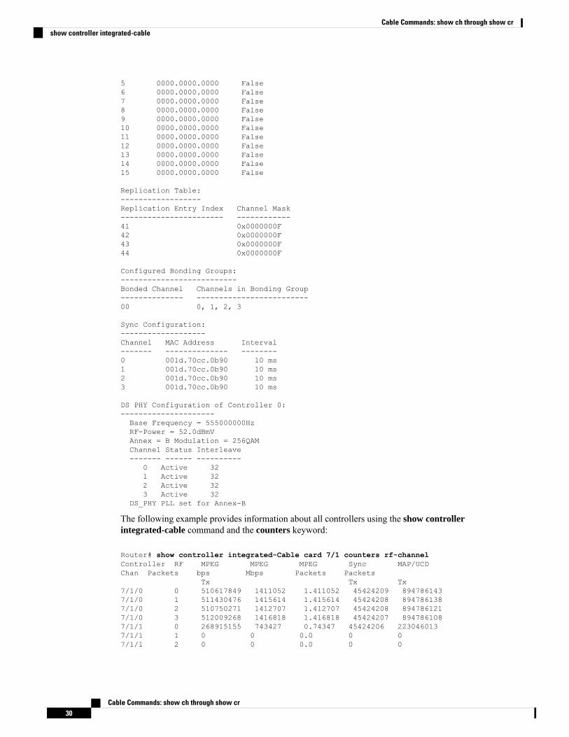
5 0000.0000.0000 False6 0000.0000.0000 False7 0000.0000.0000 False8 0000.0000.0000 False9 0000.0000.0000 False10 0000.0000.0000 False11 0000.0000.0000 False12 0000.0000.0000 False13 0000.0000.0000 False14 0000.0000.0000 False15 0000.0000.0000 False
Replication Table:------------------Replication Entry Index Channel Mask----------------------- ------------41 0x0000000F42 0x0000000F43 0x0000000F44 0x0000000F
Configured Bonding Groups:--------------------------Bonded Channel Channels in Bonding Group-------------- -------------------------00 0, 1, 2, 3
Sync Configuration:-------------------Channel MAC Address Interval------- -------------- --------0 001d.70cc.0b90 10 ms1 001d.70cc.0b90 10 ms2 001d.70cc.0b90 10 ms3 001d.70cc.0b90 10 ms
DS PHY Configuration of Controller 0:---------------------Base Frequency = 555000000HzRF-Power = 52.0dBmVAnnex = B Modulation = 256QAMChannel Status Interleave------- ------ ----------
0 Active 321 Active 322 Active 323 Active 32
DS_PHY PLL set for Annex-B
The following example provides information about all controllers using the show controllerintegrated-cable command and the counters keyword:
Router# show controller integrated-Cable card 7/1 counters rf-channelController RF MPEG MPEG MPEG Sync MAP/UCDChan Packets bps Mbps Packets Packets
Tx Tx Tx7/1/0 0 510617849 1411052 1.411052 45424209 8947861437/1/0 1 511430476 1415614 1.415614 45424208 8947861387/1/0 2 510750271 1412707 1.412707 45424208 8947861217/1/0 3 512009268 1416818 1.416818 45424207 8947861087/1/1 0 268915155 743427 0.74347 45424206 2230460137/1/1 1 0 0 0.0 0 07/1/1 2 0 0 0.0 0 0
Cable Commands: show ch through show cr30
Cable Commands: show ch through show crshow controller integrated-cable
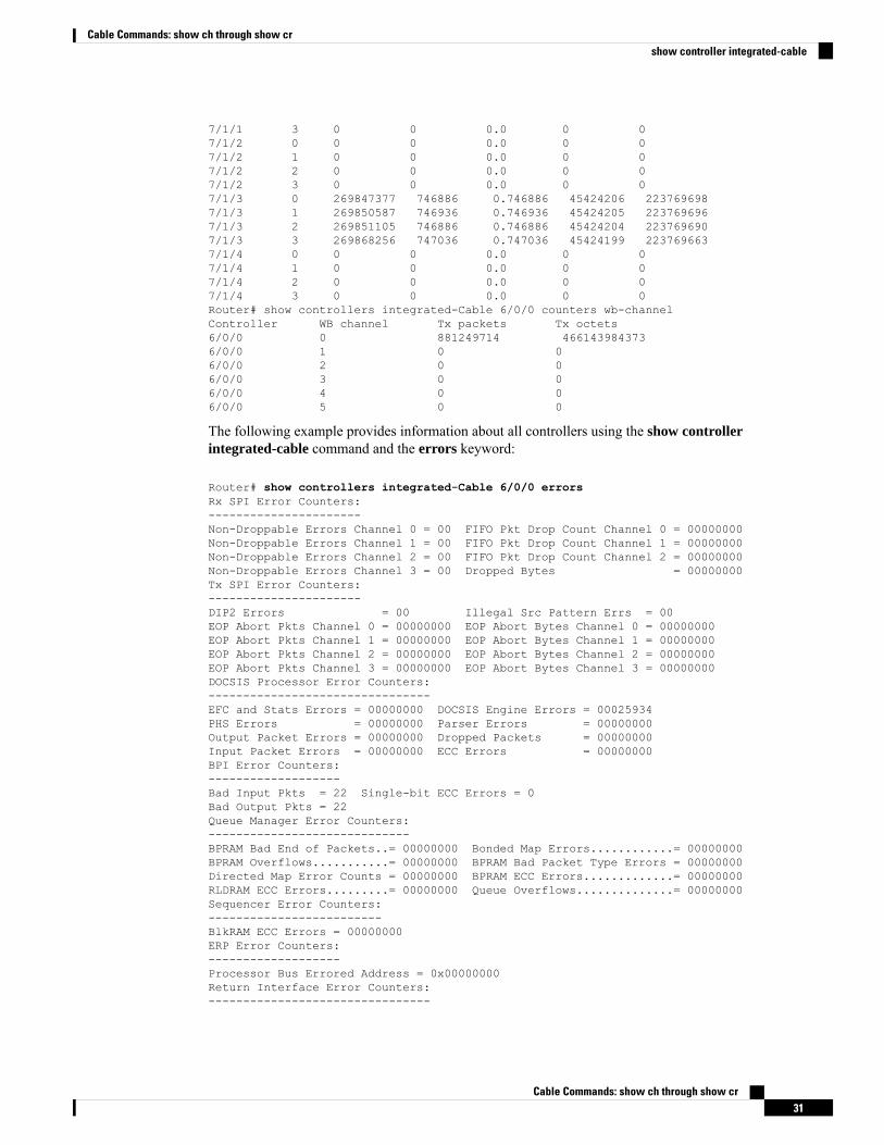
7/1/1 3 0 0 0.0 0 07/1/2 0 0 0 0.0 0 07/1/2 1 0 0 0.0 0 07/1/2 2 0 0 0.0 0 07/1/2 3 0 0 0.0 0 07/1/3 0 269847377 746886 0.746886 45424206 2237696987/1/3 1 269850587 746936 0.746936 45424205 2237696967/1/3 2 269851105 746886 0.746886 45424204 2237696907/1/3 3 269868256 747036 0.747036 45424199 2237696637/1/4 0 0 0 0.0 0 07/1/4 1 0 0 0.0 0 07/1/4 2 0 0 0.0 0 07/1/4 3 0 0 0.0 0 0Router# show controllers integrated-Cable 6/0/0 counters wb-channelController WB channel Tx packets Tx octets6/0/0 0 881249714 4661439843736/0/0 1 0 06/0/0 2 0 06/0/0 3 0 06/0/0 4 0 06/0/0 5 0 0
The following example provides information about all controllers using the show controllerintegrated-cable command and the errors keyword:
Router# show controllers integrated-Cable 6/0/0 errorsRx SPI Error Counters:----------------------Non-Droppable Errors Channel 0 = 00 FIFO Pkt Drop Count Channel 0 = 00000000Non-Droppable Errors Channel 1 = 00 FIFO Pkt Drop Count Channel 1 = 00000000Non-Droppable Errors Channel 2 = 00 FIFO Pkt Drop Count Channel 2 = 00000000Non-Droppable Errors Channel 3 = 00 Dropped Bytes = 00000000Tx SPI Error Counters:----------------------DIP2 Errors = 00 Illegal Src Pattern Errs = 00EOP Abort Pkts Channel 0 = 00000000 EOP Abort Bytes Channel 0 = 00000000EOP Abort Pkts Channel 1 = 00000000 EOP Abort Bytes Channel 1 = 00000000EOP Abort Pkts Channel 2 = 00000000 EOP Abort Bytes Channel 2 = 00000000EOP Abort Pkts Channel 3 = 00000000 EOP Abort Bytes Channel 3 = 00000000DOCSIS Processor Error Counters:--------------------------------EFC and Stats Errors = 00000000 DOCSIS Engine Errors = 00025934PHS Errors = 00000000 Parser Errors = 00000000Output Packet Errors = 00000000 Dropped Packets = 00000000Input Packet Errors = 00000000 ECC Errors = 00000000BPI Error Counters:-------------------Bad Input Pkts = 22 Single-bit ECC Errors = 0Bad Output Pkts = 22Queue Manager Error Counters:-----------------------------BPRAM Bad End of Packets..= 00000000 Bonded Map Errors............= 00000000BPRAM Overflows...........= 00000000 BPRAM Bad Packet Type Errors = 00000000Directed Map Error Counts = 00000000 BPRAM ECC Errors.............= 00000000RLDRAM ECC Errors.........= 00000000 Queue Overflows..............= 00000000Sequencer Error Counters:-------------------------BlkRAM ECC Errors = 00000000ERP Error Counters:-------------------Processor Bus Errored Address = 0x00000000Return Interface Error Counters:--------------------------------
Cable Commands: show ch through show cr31
Cable Commands: show ch through show crshow controller integrated-cable
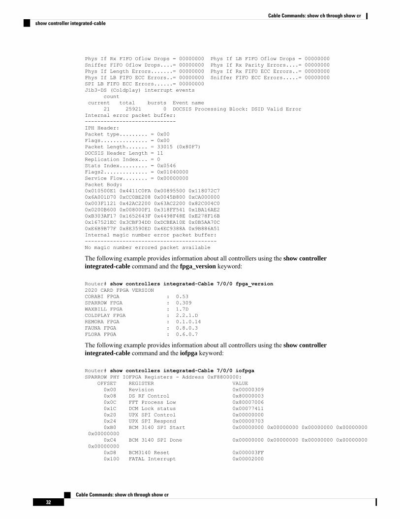
Phys If Rx FIFO Oflow Drops = 00000000 Phys If LB FIFO Oflow Drops = 00000000Sniffer FIFO Oflow Drops....= 00000000 Phys If Rx Parity Errors....= 00000000Phys If Length Errors.......= 00000000 Phys If Rx FIFO ECC Errors..= 00000000Phys If LB FIFO ECC Errors..= 00000000 Sniffer FIFO ECC Errors.....= 00000000SPI LB FIFO ECC Errors......= 00000000Jib3-DS (Coldplay) interrupt events
countcurrent total bursts Event name
21 25921 0 DOCSIS Processing Block: DSID Valid ErrorInternal error packet buffer:-----------------------------IPH Header:Packet type......... = 0x00Flags............... = 0x00Packet Length....... = 33015 (0x80F7)DOCSIS Header Length = 11Replication Index... = 0Stats Index......... = 0x0546Flags2.............. = 0x01040000Service Flow........ = 0x00000000Packet Body:0x010500E1 0x4411C0FA 0x00895500 0x118072C70x6A001D70 0xCC0BE208 0x0045B800 0xCA0000000x003F1121 0x42AC2200 0x63AC2200 0x82C004C00x0200B600 0x008000F1 0x318FF541 0x1BA16AE20xB303AF17 0x1652643F 0x4498F48E 0xE278F16B0x167521EC 0x3CBF34DD 0xDCBEA10E 0x0B5AA70C0xE6B9B77F 0x8E3590ED 0x4EC9388A 0x9B886A51Internal magic number error packet buffer:------------------------------------------No magic number errored packet available
The following example provides information about all controllers using the show controllerintegrated-cable command and the fpga_version keyword:
Router# show controllers integrated-Cable 7/0/0 fpga_version2020 CARD FPGA VERSIONCORABI FPGA : 0.53SPARROW FPGA : 0.309WAXBILL FPGA : 1.7DCOLDPLAY FPGA : 2.2.1.DREMORA FPGA : 0.1.0.14FAUNA FPGA : 0.8.0.3FLORA FPGA : 0.6.0.7
The following example provides information about all controllers using the show controllerintegrated-cable command and the iofpga keyword:
Router# show controllers integrated-Cable 7/0/0 iofpgaSPARROW PHY IOFPGA Registers - Address 0xF8800000:
OFFSET REGISTER VALUE0x00 Revision 0x000003090x08 DS RF Control 0x800000030x0C FFT Process Low 0x800070060x1C DCM Lock status 0x000774110x20 UPX SPI Control 0x000000000x24 UPX SPI Respond 0x000007030xB0 BCM 3140 SPI Start 0x00000000 0x00000000 0x00000000 0x00000000
0x000000000xC4 BCM 3140 SPI Done 0x00000000 0x00000000 0x00000000 0x00000000
0x000000000xD8 BCM3140 Reset 0x000003FF0x100 FATAL Interrupt 0x00002000
Cable Commands: show ch through show cr32
Cable Commands: show ch through show crshow controller integrated-cable
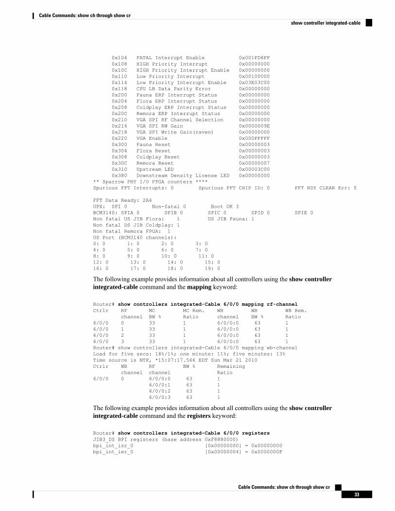
0x104 FATAL Interrupt Enable 0x001FD8FF0x108 HIGH Priority Interrupt 0x000000000x10C HIGH Priority Interrupt Enable 0x000000000x110 Low Priority Interrupt 0x001000000x114 Low Priority Interrupt Enable 0x03E03C000x118 CPU LB Data Parity Error 0x000000000x200 Fauna ERP Interrupt Status 0x000000000x204 Flora ERP Interrupt Status 0x000000000x208 Coldplay ERP Interrupt Status 0x000000000x20C Remora ERP Interrupt Status 0x000000000x210 VGA SPI RF Channel Selection 0x000000000x214 VGA SPI RW Gain 0x0000009E0x218 VGA SPI Write Gain(raven) 0x000000000x220 VGA Enable 0x000FFFFF0x300 Fauna Reset 0x000000030x304 Flora Reset 0x000000030x308 Coldplay Reset 0x000000030x30C Remora Reset 0x000000070x310 Upstream LED 0x00003C000x380 Downstream Density License LED 0x00000000
** Sparrow PHY I/O FPGA counters ****Spurious FFT Interrupts: 0 Spurious FFT CHIP ID: 0 FFT RDY CLEAR Err: 0
FFT Data Ready: 2A6UPX: SPI 0 Non-fatal 0 Boot OK 3BCM3140: SPIA 0 SPIB 0 SPIC 0 SPID 0 SPIE 0Non fatal US JIB Flora: 1 US JIB Fauna: 1Non fatal DS JIB Coldplay: 1Non fatal Remora FPGA: 1US Port (BCM3140 channels):0: 0 1: 0 2: 0 3: 04: 0 5: 0 6: 0 7: 08: 0 9: 0 10: 0 11: 012: 0 13: 0 14: 0 15: 016: 0 17: 0 18: 0 19: 0
The following example provides information about all controllers using the show controllerintegrated-cable command and the mapping keyword:
Router# show controllers integrated-Cable 6/0/0 mapping rf-channelCtrlr RF MC MC Rem. WB WB WB Rem.
channel BW % Ratio channel BW % Ratio6/0/0 0 33 1 6/0/0:0 63 16/0/0 1 33 1 6/0/0:0 63 16/0/0 2 33 1 6/0/0:0 63 16/0/0 3 33 1 6/0/0:0 63 1Router# show controllers integrated-Cable 6/0/0 mapping wb-channelLoad for five secs: 18%/1%; one minute: 11%; five minutes: 13%Time source is NTP, *15:07:17.566 EDT Sun Mar 21 2010Ctrlr WB RF BW % Remaining
channel channel Ratio6/0/0 0 6/0/0:0 63 1
6/0/0:1 63 16/0/0:2 63 16/0/0:3 63 1
The following example provides information about all controllers using the show controllerintegrated-cable command and the registers keyword:
Router# show controllers integrated-Cable 6/0/0 registersJIB3_DS BPI registers (base address 0xF8880000)bpi_int_isr_0 [0x00000000] = 0x00000000bpi_int_ier_0 [0x00000004] = 0x0000000F
Cable Commands: show ch through show cr33
Cable Commands: show ch through show crshow controller integrated-cable
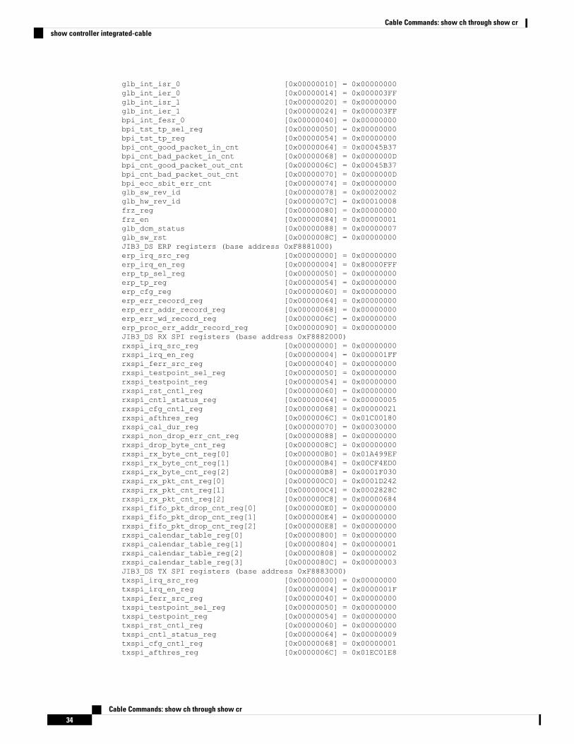
glb_int_isr_0 [0x00000010] = 0x00000000glb_int_ier_0 [0x00000014] = 0x000003FFglb_int_isr_1 [0x00000020] = 0x00000000glb_int_ier_1 [0x00000024] = 0x000003FFbpi_int_fesr_0 [0x00000040] = 0x00000000bpi_tst_tp_sel_reg [0x00000050] = 0x00000000bpi_tst_tp_reg [0x00000054] = 0x00000000bpi_cnt_good_packet_in_cnt [0x00000064] = 0x00045B37bpi_cnt_bad_packet_in_cnt [0x00000068] = 0x0000000Dbpi_cnt_good_packet_out_cnt [0x0000006C] = 0x00045B37bpi_cnt_bad_packet_out_cnt [0x00000070] = 0x0000000Dbpi_ecc_sbit_err_cnt [0x00000074] = 0x00000000glb_sw_rev_id [0x00000078] = 0x00020002glb_hw_rev_id [0x0000007C] = 0x00010008frz_reg [0x00000080] = 0x00000000frz_en [0x00000084] = 0x00000001glb_dcm_status [0x00000088] = 0x00000007glb_sw_rst [0x0000008C] = 0x00000000JIB3_DS ERP registers (base address 0xF8881000)erp_irq_src_reg [0x00000000] = 0x00000000erp_irq_en_reg [0x00000004] = 0x80000FFFerp_tp_sel_reg [0x00000050] = 0x00000000erp_tp_reg [0x00000054] = 0x00000000erp_cfg_reg [0x00000060] = 0x00000000erp_err_record_reg [0x00000064] = 0x00000000erp_err_addr_record_reg [0x00000068] = 0x00000000erp_err_wd_record_reg [0x0000006C] = 0x00000000erp_proc_err_addr_record_reg [0x00000090] = 0x00000000JIB3_DS RX SPI registers (base address 0xF8882000)rxspi_irq_src_reg [0x00000000] = 0x00000000rxspi_irq_en_reg [0x00000004] = 0x000001FFrxspi_ferr_src_reg [0x00000040] = 0x00000000rxspi_testpoint_sel_reg [0x00000050] = 0x00000000rxspi_testpoint_reg [0x00000054] = 0x00000000rxspi_rst_cntl_reg [0x00000060] = 0x00000000rxspi_cntl_status_reg [0x00000064] = 0x00000005rxspi_cfg_cntl_reg [0x00000068] = 0x00000021rxspi_afthres_reg [0x0000006C] = 0x01C00180rxspi_cal_dur_reg [0x00000070] = 0x00030000rxspi_non_drop_err_cnt_reg [0x00000088] = 0x00000000rxspi_drop_byte_cnt_reg [0x0000008C] = 0x00000000rxspi_rx_byte_cnt_reg[0] [0x000000B0] = 0x01A499EFrxspi_rx_byte_cnt_reg[1] [0x000000B4] = 0x00CF4ED0rxspi_rx_byte_cnt_reg[2] [0x000000B8] = 0x0001F030rxspi_rx_pkt_cnt_reg[0] [0x000000C0] = 0x0001D242rxspi_rx_pkt_cnt_reg[1] [0x000000C4] = 0x0002828Crxspi_rx_pkt_cnt_reg[2] [0x000000C8] = 0x00000684rxspi_fifo_pkt_drop_cnt_reg[0] [0x000000E0] = 0x00000000rxspi_fifo_pkt_drop_cnt_reg[1] [0x000000E4] = 0x00000000rxspi_fifo_pkt_drop_cnt_reg[2] [0x000000E8] = 0x00000000rxspi_calendar_table_reg[0] [0x00000800] = 0x00000000rxspi_calendar_table_reg[1] [0x00000804] = 0x00000001rxspi_calendar_table_reg[2] [0x00000808] = 0x00000002rxspi_calendar_table_reg[3] [0x0000080C] = 0x00000003JIB3_DS TX SPI registers (base address 0xF8883000)txspi_irq_src_reg [0x00000000] = 0x00000000txspi_irq_en_reg [0x00000004] = 0x0000001Ftxspi_ferr_src_reg [0x00000040] = 0x00000000txspi_testpoint_sel_reg [0x00000050] = 0x00000000txspi_testpoint_reg [0x00000054] = 0x00000000txspi_rst_cntl_reg [0x00000060] = 0x00000000txspi_cntl_status_reg [0x00000064] = 0x00000009txspi_cfg_cntl_reg [0x00000068] = 0x00000001txspi_afthres_reg [0x0000006C] = 0x01EC01E8
Cable Commands: show ch through show cr34
Cable Commands: show ch through show crshow controller integrated-cable
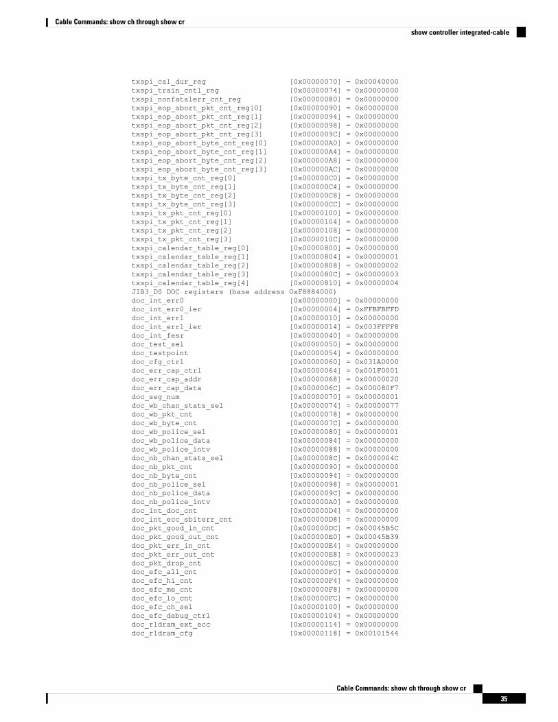
txspi_cal_dur_reg [0x00000070] = 0x00040000txspi_train_cntl_reg [0x00000074] = 0x00000000txspi_nonfatalerr_cnt_reg [0x00000080] = 0x00000000txspi_eop_abort_pkt_cnt_reg[0] [0x00000090] = 0x00000000txspi_eop_abort_pkt_cnt_reg[1] [0x00000094] = 0x00000000txspi_eop_abort_pkt_cnt_reg[2] [0x00000098] = 0x00000000txspi_eop_abort_pkt_cnt_reg[3] [0x0000009C] = 0x00000000txspi_eop_abort_byte_cnt_reg[0] [0x000000A0] = 0x00000000txspi_eop_abort_byte_cnt_reg[1] [0x000000A4] = 0x00000000txspi_eop_abort_byte_cnt_reg[2] [0x000000A8] = 0x00000000txspi_eop_abort_byte_cnt_reg[3] [0x000000AC] = 0x00000000txspi_tx_byte_cnt_reg[0] [0x000000C0] = 0x00000000txspi_tx_byte_cnt_reg[1] [0x000000C4] = 0x00000000txspi_tx_byte_cnt_reg[2] [0x000000C8] = 0x00000000txspi_tx_byte_cnt_reg[3] [0x000000CC] = 0x00000000txspi_tx_pkt_cnt_reg[0] [0x00000100] = 0x00000000txspi_tx_pkt_cnt_reg[1] [0x00000104] = 0x00000000txspi_tx_pkt_cnt_reg[2] [0x00000108] = 0x00000000txspi_tx_pkt_cnt_reg[3] [0x0000010C] = 0x00000000txspi_calendar_table_reg[0] [0x00000800] = 0x00000000txspi_calendar_table_reg[1] [0x00000804] = 0x00000001txspi_calendar_table_reg[2] [0x00000808] = 0x00000002txspi_calendar_table_reg[3] [0x0000080C] = 0x00000003txspi_calendar_table_reg[4] [0x00000810] = 0x00000004JIB3_DS DOC registers (base address 0xF8884000)doc_int_err0 [0x00000000] = 0x00000000doc_int_err0_ier [0x00000004] = 0xFFBFBFFDdoc_int_err1 [0x00000010] = 0x00000000doc_int_err1_ier [0x00000014] = 0x003FFFF8doc_int_fesr [0x00000040] = 0x00000000doc_test_sel [0x00000050] = 0x00000000doc_testpoint [0x00000054] = 0x00000000doc_cfg_ctrl [0x00000060] = 0x031A0000doc_err_cap_ctrl [0x00000064] = 0x001F0001doc_err_cap_addr [0x00000068] = 0x00000020doc_err_cap_data [0x0000006C] = 0x000080F7doc_seg_num [0x00000070] = 0x00000001doc_wb_chan_stats_sel [0x00000074] = 0x00000077doc_wb_pkt_cnt [0x00000078] = 0x00000000doc_wb_byte_cnt [0x0000007C] = 0x00000000doc_wb_police_sel [0x00000080] = 0x00000001doc_wb_police_data [0x00000084] = 0x00000000doc_wb_police_intv [0x00000088] = 0x00000000doc_nb_chan_stats_sel [0x0000008C] = 0x0000004Cdoc_nb_pkt_cnt [0x00000090] = 0x00000000doc_nb_byte_cnt [0x00000094] = 0x00000000doc_nb_police_sel [0x00000098] = 0x00000001doc_nb_police_data [0x0000009C] = 0x00000000doc_nb_police_intv [0x000000A0] = 0x00000000doc_int_doc_cnt [0x000000D4] = 0x00000000doc_int_ecc_sbiterr_cnt [0x000000D8] = 0x00000000doc_pkt_good_in_cnt [0x000000DC] = 0x00045B5Cdoc_pkt_good_out_cnt [0x000000E0] = 0x00045B39doc_pkt_err_in_cnt [0x000000E4] = 0x00000000doc_pkt_err_out_cnt [0x000000E8] = 0x00000023doc_pkt_drop_cnt [0x000000EC] = 0x00000000doc_efc_all_cnt [0x000000F0] = 0x00000000doc_efc_hi_cnt [0x000000F4] = 0x00000000doc_efc_me_cnt [0x000000F8] = 0x00000000doc_efc_lo_cnt [0x000000FC] = 0x00000000doc_efc_ch_sel [0x00000100] = 0x00000000doc_efc_debug_ctrl [0x00000104] = 0x00000000doc_rldram_ext_ecc [0x00000114] = 0x00000000doc_rldram_cfg [0x00000118] = 0x00101544
Cable Commands: show ch through show cr35
Cable Commands: show ch through show crshow controller integrated-cable
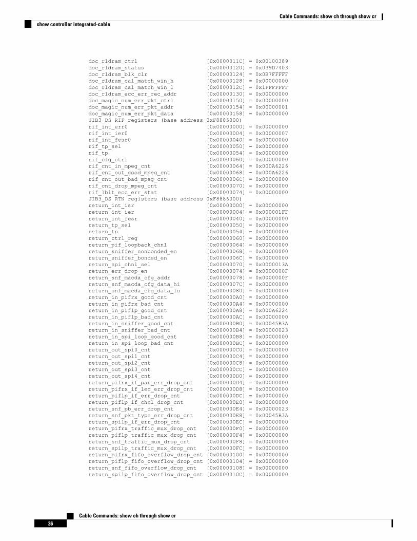
doc_rldram_ctrl [0x0000011C] = 0x00100389doc_rldram_status [0x00000120] = 0x039D7403doc_rldram_blk_clr [0x00000124] = 0x0B7FFFFFdoc_rldram_cal_match_win_h [0x00000128] = 0x00000000doc_rldram_cal_match_win_l [0x0000012C] = 0x1FFFFFFFdoc_rldram_ecc_err_rec_addr [0x00000130] = 0x00000000doc_magic_num_err_pkt_ctrl [0x00000150] = 0x00000000doc_magic_num_err_pkt_addr [0x00000154] = 0x00000001doc_magic_num_err_pkt_data [0x00000158] = 0x00000000JIB3_DS RIF registers (base address 0xF8885000)rif_int_err0 [0x00000000] = 0x00000000rif_int_ier0 [0x00000004] = 0x00000007rif_int_fesr0 [0x00000040] = 0x00000000rif_tp_sel [0x00000050] = 0x00000000rif_tp [0x00000054] = 0x00000000rif_cfg_ctrl [0x00000060] = 0x00000000rif_cnt_in_mpeg_cnt [0x00000064] = 0x000A6226rif_cnt_out_good_mpeg_cnt [0x00000068] = 0x000A6226rif_cnt_out_bad_mpeg_cnt [0x0000006C] = 0x00000000rif_cnt_drop_mpeg_cnt [0x00000070] = 0x00000000rif_1bit_ecc_err_stat [0x00000074] = 0x00000000JIB3_DS RTN registers (base address 0xF8886000)return_int_isr [0x00000000] = 0x00000000return_int_ier [0x00000004] = 0x000001FFreturn_int_fesr [0x00000040] = 0x00000000return_tp_sel [0x00000050] = 0x00000000return_tp [0x00000054] = 0x00000000return_ctrl_reg [0x00000060] = 0x00000000return_pif_loopback_chnl [0x00000064] = 0x00000000return_sniffer_nonbonded_en [0x00000068] = 0x00000000return_sniffer_bonded_en [0x0000006C] = 0x00000000return_spi_chnl_sel [0x00000070] = 0x0000013Areturn_err_drop_en [0x00000074] = 0x0000000Freturn_snf_macda_cfg_addr [0x00000078] = 0x0000000Freturn_snf_macda_cfg_data_hi [0x0000007C] = 0x00000000return_snf_macda_cfg_data_lo [0x00000080] = 0x00000000return_in_pifrx_good_cnt [0x000000A0] = 0x00000000return_in_pifrx_bad_cnt [0x000000A4] = 0x00000000return_in_piflp_good_cnt [0x000000A8] = 0x000A6224return_in_piflp_bad_cnt [0x000000AC] = 0x00000000return_in_sniffer_good_cnt [0x000000B0] = 0x00045B3Areturn_in_sniffer_bad_cnt [0x000000B4] = 0x00000023return_in_spi_loop_good_cnt [0x000000B8] = 0x00000000return_in_spi_loop_bad_cnt [0x000000BC] = 0x00000000return_out_spi0_cnt [0x000000C0] = 0x00000000return_out_spi1_cnt [0x000000C4] = 0x00000000return_out_spi2_cnt [0x000000C8] = 0x00000000return_out_spi3_cnt [0x000000CC] = 0x00000000return_out_spi4_cnt [0x000000D0] = 0x00000000return_pifrx_if_par_err_drop_cnt [0x000000D4] = 0x00000000return_pifrx_if_len_err_drop_cnt [0x000000D8] = 0x00000000return_piflp_if_err_drop_cnt [0x000000DC] = 0x00000000return_piflp_if_chnl_drop_cnt [0x000000E0] = 0x00000000return_snf_pb_err_drop_cnt [0x000000E4] = 0x00000023return_snf_pkt_type_err_drop_cnt [0x000000E8] = 0x00045B3Areturn_spilp_if_err_drop_cnt [0x000000EC] = 0x00000000return_pifrx_traffic_mux_drop_cnt [0x000000F0] = 0x00000000return_piflp_traffic_mux_drop_cnt [0x000000F4] = 0x00000000return_snf_traffic_mux_drop_cnt [0x000000F8] = 0x00000000return_spilp_traffic_mux_drop_cnt [0x000000FC] = 0x00000000return_pifrx_fifo_overflow_drop_cnt [0x00000100] = 0x00000000return_piflp_fifo_overflow_drop_cnt [0x00000104] = 0x00000000return_snf_fifo_overflow_drop_cnt [0x00000108] = 0x00000000return_spilp_fifo_overflow_drop_cnt [0x0000010C] = 0x00000000
Cable Commands: show ch through show cr36
Cable Commands: show ch through show crshow controller integrated-cable
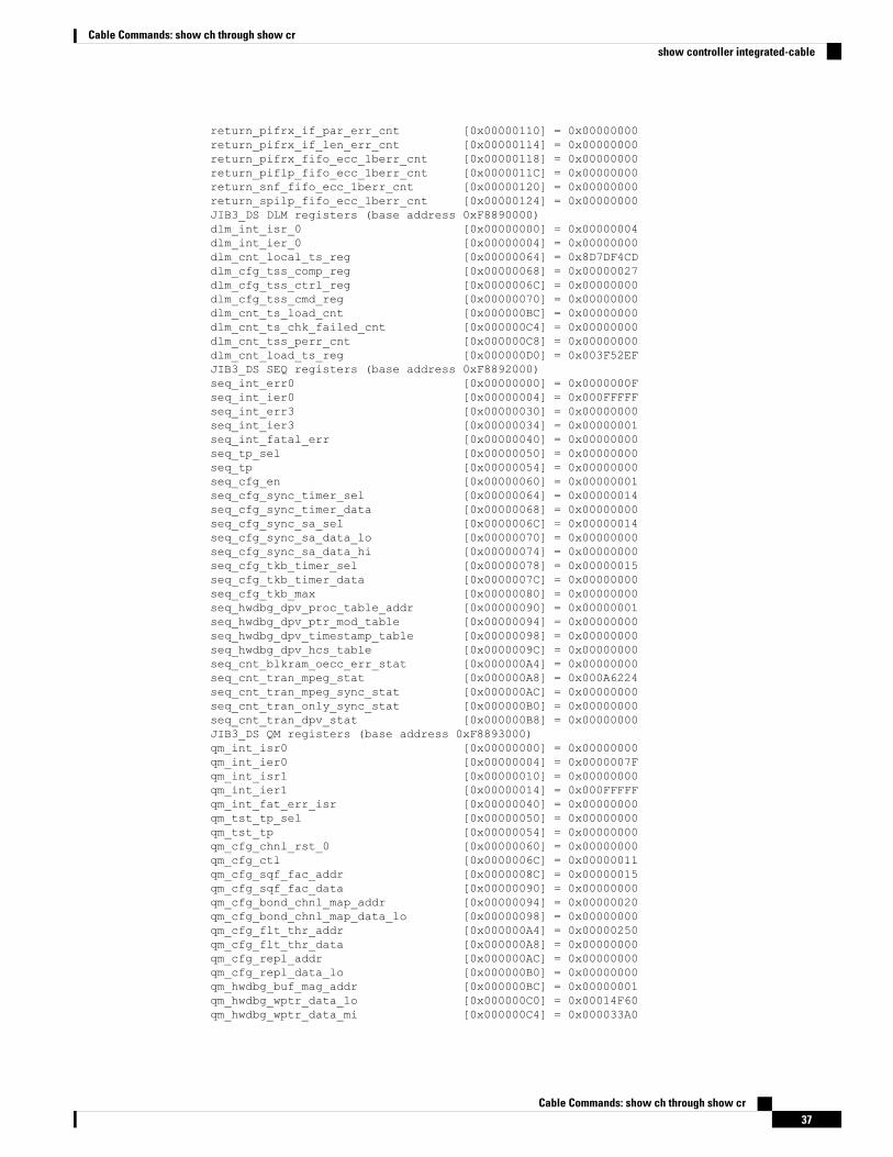
return_pifrx_if_par_err_cnt [0x00000110] = 0x00000000return_pifrx_if_len_err_cnt [0x00000114] = 0x00000000return_pifrx_fifo_ecc_1berr_cnt [0x00000118] = 0x00000000return_piflp_fifo_ecc_1berr_cnt [0x0000011C] = 0x00000000return_snf_fifo_ecc_1berr_cnt [0x00000120] = 0x00000000return_spilp_fifo_ecc_1berr_cnt [0x00000124] = 0x00000000JIB3_DS DLM registers (base address 0xF8890000)dlm_int_isr_0 [0x00000000] = 0x00000004dlm_int_ier_0 [0x00000004] = 0x00000000dlm_cnt_local_ts_reg [0x00000064] = 0x8D7DF4CDdlm_cfg_tss_comp_reg [0x00000068] = 0x00000027dlm_cfg_tss_ctrl_reg [0x0000006C] = 0x00000000dlm_cfg_tss_cmd_reg [0x00000070] = 0x00000000dlm_cnt_ts_load_cnt [0x000000BC] = 0x00000000dlm_cnt_ts_chk_failed_cnt [0x000000C4] = 0x00000000dlm_cnt_tss_perr_cnt [0x000000C8] = 0x00000000dlm_cnt_load_ts_reg [0x000000D0] = 0x003F52EFJIB3_DS SEQ registers (base address 0xF8892000)seq_int_err0 [0x00000000] = 0x0000000Fseq_int_ier0 [0x00000004] = 0x000FFFFFseq_int_err3 [0x00000030] = 0x00000000seq_int_ier3 [0x00000034] = 0x00000001seq_int_fatal_err [0x00000040] = 0x00000000seq_tp_sel [0x00000050] = 0x00000000seq_tp [0x00000054] = 0x00000000seq_cfg_en [0x00000060] = 0x00000001seq_cfg_sync_timer_sel [0x00000064] = 0x00000014seq_cfg_sync_timer_data [0x00000068] = 0x00000000seq_cfg_sync_sa_sel [0x0000006C] = 0x00000014seq_cfg_sync_sa_data_lo [0x00000070] = 0x00000000seq_cfg_sync_sa_data_hi [0x00000074] = 0x00000000seq_cfg_tkb_timer_sel [0x00000078] = 0x00000015seq_cfg_tkb_timer_data [0x0000007C] = 0x00000000seq_cfg_tkb_max [0x00000080] = 0x00000000seq_hwdbg_dpv_proc_table_addr [0x00000090] = 0x00000001seq_hwdbg_dpv_ptr_mod_table [0x00000094] = 0x00000000seq_hwdbg_dpv_timestamp_table [0x00000098] = 0x00000000seq_hwdbg_dpv_hcs_table [0x0000009C] = 0x00000000seq_cnt_blkram_oecc_err_stat [0x000000A4] = 0x00000000seq_cnt_tran_mpeg_stat [0x000000A8] = 0x000A6224seq_cnt_tran_mpeg_sync_stat [0x000000AC] = 0x00000000seq_cnt_tran_only_sync_stat [0x000000B0] = 0x00000000seq_cnt_tran_dpv_stat [0x000000B8] = 0x00000000JIB3_DS QM registers (base address 0xF8893000)qm_int_isr0 [0x00000000] = 0x00000000qm_int_ier0 [0x00000004] = 0x0000007Fqm_int_isr1 [0x00000010] = 0x00000000qm_int_ier1 [0x00000014] = 0x000FFFFFqm_int_fat_err_isr [0x00000040] = 0x00000000qm_tst_tp_sel [0x00000050] = 0x00000000qm_tst_tp [0x00000054] = 0x00000000qm_cfg_chnl_rst_0 [0x00000060] = 0x00000000qm_cfg_ctl [0x0000006C] = 0x00000011qm_cfg_sqf_fac_addr [0x0000008C] = 0x00000015qm_cfg_sqf_fac_data [0x00000090] = 0x00000000qm_cfg_bond_chnl_map_addr [0x00000094] = 0x00000020qm_cfg_bond_chnl_map_data_lo [0x00000098] = 0x00000000qm_cfg_flt_thr_addr [0x000000A4] = 0x00000250qm_cfg_flt_thr_data [0x000000A8] = 0x00000000qm_cfg_repl_addr [0x000000AC] = 0x00000000qm_cfg_repl_data_lo [0x000000B0] = 0x00000000qm_hwdbg_buf_mag_addr [0x000000BC] = 0x00000001qm_hwdbg_wptr_data_lo [0x000000C0] = 0x00014F60qm_hwdbg_wptr_data_mi [0x000000C4] = 0x000033A0
Cable Commands: show ch through show cr37
Cable Commands: show ch through show crshow controller integrated-cable
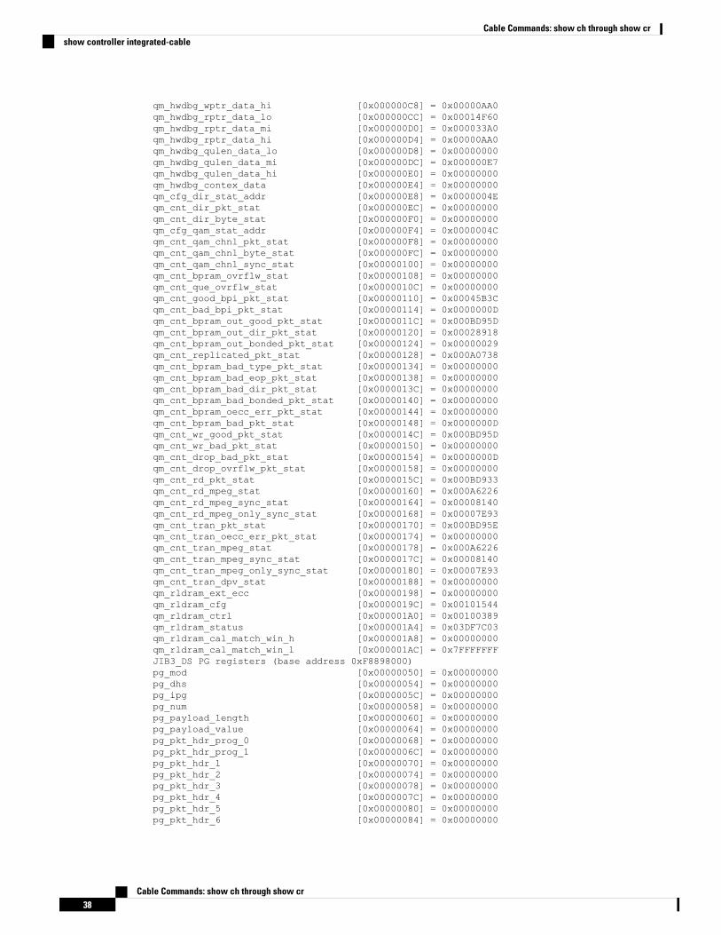
qm_hwdbg_wptr_data_hi [0x000000C8] = 0x00000AA0qm_hwdbg_rptr_data_lo [0x000000CC] = 0x00014F60qm_hwdbg_rptr_data_mi [0x000000D0] = 0x000033A0qm_hwdbg_rptr_data_hi [0x000000D4] = 0x00000AA0qm_hwdbg_qulen_data_lo [0x000000D8] = 0x00000000qm_hwdbg_qulen_data_mi [0x000000DC] = 0x000000E7qm_hwdbg_qulen_data_hi [0x000000E0] = 0x00000000qm_hwdbg_contex_data [0x000000E4] = 0x00000000qm_cfg_dir_stat_addr [0x000000E8] = 0x0000004Eqm_cnt_dir_pkt_stat [0x000000EC] = 0x00000000qm_cnt_dir_byte_stat [0x000000F0] = 0x00000000qm_cfg_qam_stat_addr [0x000000F4] = 0x0000004Cqm_cnt_qam_chnl_pkt_stat [0x000000F8] = 0x00000000qm_cnt_qam_chnl_byte_stat [0x000000FC] = 0x00000000qm_cnt_qam_chnl_sync_stat [0x00000100] = 0x00000000qm_cnt_bpram_ovrflw_stat [0x00000108] = 0x00000000qm_cnt_que_ovrflw_stat [0x0000010C] = 0x00000000qm_cnt_good_bpi_pkt_stat [0x00000110] = 0x00045B3Cqm_cnt_bad_bpi_pkt_stat [0x00000114] = 0x0000000Dqm_cnt_bpram_out_good_pkt_stat [0x0000011C] = 0x000BD95Dqm_cnt_bpram_out_dir_pkt_stat [0x00000120] = 0x00028918qm_cnt_bpram_out_bonded_pkt_stat [0x00000124] = 0x00000029qm_cnt_replicated_pkt_stat [0x00000128] = 0x000A0738qm_cnt_bpram_bad_type_pkt_stat [0x00000134] = 0x00000000qm_cnt_bpram_bad_eop_pkt_stat [0x00000138] = 0x00000000qm_cnt_bpram_bad_dir_pkt_stat [0x0000013C] = 0x00000000qm_cnt_bpram_bad_bonded_pkt_stat [0x00000140] = 0x00000000qm_cnt_bpram_oecc_err_pkt_stat [0x00000144] = 0x00000000qm_cnt_bpram_bad_pkt_stat [0x00000148] = 0x0000000Dqm_cnt_wr_good_pkt_stat [0x0000014C] = 0x000BD95Dqm_cnt_wr_bad_pkt_stat [0x00000150] = 0x00000000qm_cnt_drop_bad_pkt_stat [0x00000154] = 0x0000000Dqm_cnt_drop_ovrflw_pkt_stat [0x00000158] = 0x00000000qm_cnt_rd_pkt_stat [0x0000015C] = 0x000BD933qm_cnt_rd_mpeg_stat [0x00000160] = 0x000A6226qm_cnt_rd_mpeg_sync_stat [0x00000164] = 0x00008140qm_cnt_rd_mpeg_only_sync_stat [0x00000168] = 0x00007E93qm_cnt_tran_pkt_stat [0x00000170] = 0x000BD95Eqm_cnt_tran_oecc_err_pkt_stat [0x00000174] = 0x00000000qm_cnt_tran_mpeg_stat [0x00000178] = 0x000A6226qm_cnt_tran_mpeg_sync_stat [0x0000017C] = 0x00008140qm_cnt_tran_mpeg_only_sync_stat [0x00000180] = 0x00007E93qm_cnt_tran_dpv_stat [0x00000188] = 0x00000000qm_rldram_ext_ecc [0x00000198] = 0x00000000qm_rldram_cfg [0x0000019C] = 0x00101544qm_rldram_ctrl [0x000001A0] = 0x00100389qm_rldram_status [0x000001A4] = 0x03DF7C03qm_rldram_cal_match_win_h [0x000001A8] = 0x00000000qm_rldram_cal_match_win_l [0x000001AC] = 0x7FFFFFFFJIB3_DS PG registers (base address 0xF8898000)pg_mod [0x00000050] = 0x00000000pg_dhs [0x00000054] = 0x00000000pg_ipg [0x0000005C] = 0x00000000pg_num [0x00000058] = 0x00000000pg_payload_length [0x00000060] = 0x00000000pg_payload_value [0x00000064] = 0x00000000pg_pkt_hdr_prog_0 [0x00000068] = 0x00000000pg_pkt_hdr_prog_1 [0x0000006C] = 0x00000000pg_pkt_hdr_1 [0x00000070] = 0x00000000pg_pkt_hdr_2 [0x00000074] = 0x00000000pg_pkt_hdr_3 [0x00000078] = 0x00000000pg_pkt_hdr_4 [0x0000007C] = 0x00000000pg_pkt_hdr_5 [0x00000080] = 0x00000000pg_pkt_hdr_6 [0x00000084] = 0x00000000
Cable Commands: show ch through show cr38
Cable Commands: show ch through show crshow controller integrated-cable
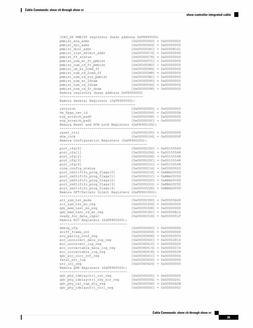
JIB3_DS PMBIST registers (base address 0xF8899000)pmbist_ena_addr [0x00000060] = 0x00000002pmbist_din_addr [0x00000064] = 0x00000000pmbist_dout_addr [0x0000006C] = 0x00008101pmbist_trgt_select_addr [0x00000074] = 0x00000000pmbist_ff_status [0x00000078] = 0x00000000pmbist_num_wr_fr_pmbist [0x0000007C] = 0x00000000pmbist_num_rd_fr_pmbist [0x00000080] = 0x00000000pmbist_um_wr_2cmd_ff [0x00000084] = 0x00000000pmbist_num_rd_2cmd_ff [0x00000088] = 0x00000000pmbist_num_rd_rtn_pmbist [0x0000008C] = 0x00000000pmbist_num_wr_2dram [0x00000090] = 0x00000000pmbist_num_rd_2dram [0x00000094] = 0x00000000pmbist_num_rd_fr_dram [0x00000098] = 0x00000000Remora registers (base address 0xF8900000)------------------------------------------Remora General Registers (0xF8900000):--------------------------------------revision [0x00000000] = 0x00000003hw_fpga_rev_id [0x00000004] = 0x0000000Aerp_scratch_pad0 [0x00000008] = 0x00000000erp_scratch_pad1 [0x0000000C] = 0x00000000Remora Reset and DCM Lock Registers (0xF8900100):-----------------------------------------------reset_ctrl [0x00000100] = 0x00000000dcm_lock [0x00000104] = 0x0000000FRemora Configuration Registers (0xF8900200):--------------------------------------------port_cfg[0] [0x00000200] = 0x00155549port_cfg[1] [0x00000204] = 0x00155548port_cfg[2] [0x00000208] = 0x00155548port_cfg[3] [0x0000020C] = 0x00155548port_cfg[4] [0x00000210] = 0x00155548core_config_status [0x00000214] = 0x00000020port_rm2tififo_prog_flags[0] [0x00000218] = 0xBBA20C0Dport_rm2tififo_prog_flags[1] [0x0000021C] = 0xBBA20C0Dport_rm2tififo_prog_flags[2] [0x00000220] = 0xBBA20C0Dport_rm2tififo_prog_flags[3] [0x00000224] = 0xBBA20C0Dport_rm2tififo_prog_flags[4] [0x00000228] = 0xBBA20C0DRemora DFT/Pattern Inject Registers (0xF8900300):-------------------------------------------------alt_sym_tst_mode [0x00000300] = 0x00005A69alt_sym_tst_en_reg [0x00000304] = 0x00000000qdr_mem_test_en_reg [0x00000308] = 0x00000000qdr_mem_test_rd_wr_reg [0x0000030C] = 0x00000A12ready_for_data_input [0x00000318] = 0x0000001FRemora ECC Registers (0xF8900400):----------------------------------debug_cfg [0x00000400] = 0x00000000sniff_frame_cnt [0x00000404] = 0x00000000ecc_parity_conf_reg [0x00000408] = 0x00000003ecc_uncorrect_data_log_reg [0x0000040C] = 0x00002814ecc_uncorrect_log_reg [0x00000410] = 0x00000020ecc_correctable_data_log_reg [0x00000414] = 0x00002C14ecc_correctable_log_reg [0x00000418] = 0x00000028qdr_ecc_corr_cnt_reg [0x0000041C] = 0x00000000fatal_err_log [0x00000420] = 0x00000000err_inj_reg [0x00000424] = 0x00000000Remora QDR Registers (0xF8900500):----------------------------------qdr_phy_idelayctrl_rst_reg [0x00000500] = 0x00000000qdr_phy_idelayctrl_rdy_err_reg [0x00000504] = 0x00000261qdr_phy_cal_tap_dly_reg [0x00000508] = 0x00000ADBqdr_phy_idelayctrl_ctrl_reg [0x0000050C] = 0x00000002
Cable Commands: show ch through show cr39
Cable Commands: show ch through show crshow controller integrated-cable
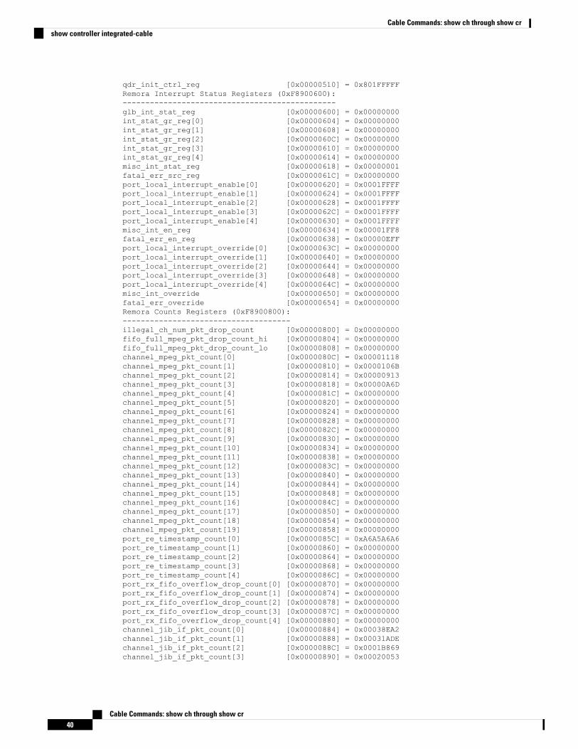
qdr_init_ctrl_reg [0x00000510] = 0x801FFFFFRemora Interrupt Status Registers (0xF8900600):-----------------------------------------------glb_int_stat_reg [0x00000600] = 0x00000000int_stat_gr_reg[0] [0x00000604] = 0x00000000int_stat_gr_reg[1] [0x00000608] = 0x00000000int_stat_gr_reg[2] [0x0000060C] = 0x00000000int_stat_gr_reg[3] [0x00000610] = 0x00000000int_stat_gr_reg[4] [0x00000614] = 0x00000000misc_int_stat_reg [0x00000618] = 0x00000001fatal_err_src_reg [0x0000061C] = 0x00000000port_local_interrupt_enable[0] [0x00000620] = 0x0001FFFFport_local_interrupt_enable[1] [0x00000624] = 0x0001FFFFport_local_interrupt_enable[2] [0x00000628] = 0x0001FFFFport_local_interrupt_enable[3] [0x0000062C] = 0x0001FFFFport_local_interrupt_enable[4] [0x00000630] = 0x0001FFFFmisc_int_en_reg [0x00000634] = 0x00001FF8fatal_err_en_reg [0x00000638] = 0x00000EFFport_local_interrupt_override[0] [0x0000063C] = 0x00000000port_local_interrupt_override[1] [0x00000640] = 0x00000000port_local_interrupt_override[2] [0x00000644] = 0x00000000port_local_interrupt_override[3] [0x00000648] = 0x00000000port_local_interrupt_override[4] [0x0000064C] = 0x00000000misc_int_override [0x00000650] = 0x00000000fatal_err_override [0x00000654] = 0x00000000Remora Counts Registers (0xF8900800):-------------------------------------illegal_ch_num_pkt_drop_count [0x00000800] = 0x00000000fifo_full_mpeg_pkt_drop_count_hi [0x00000804] = 0x00000000fifo_full_mpeg_pkt_drop_count_lo [0x00000808] = 0x00000000channel_mpeg_pkt_count[0] [0x0000080C] = 0x00001118channel_mpeg_pkt_count[1] [0x00000810] = 0x0000106Bchannel_mpeg_pkt_count[2] [0x00000814] = 0x00000913channel_mpeg_pkt_count[3] [0x00000818] = 0x00000A6Dchannel_mpeg_pkt_count[4] [0x0000081C] = 0x00000000channel_mpeg_pkt_count[5] [0x00000820] = 0x00000000channel_mpeg_pkt_count[6] [0x00000824] = 0x00000000channel_mpeg_pkt_count[7] [0x00000828] = 0x00000000channel_mpeg_pkt_count[8] [0x0000082C] = 0x00000000channel_mpeg_pkt_count[9] [0x00000830] = 0x00000000channel_mpeg_pkt_count[10] [0x00000834] = 0x00000000channel_mpeg_pkt_count[11] [0x00000838] = 0x00000000channel_mpeg_pkt_count[12] [0x0000083C] = 0x00000000channel_mpeg_pkt_count[13] [0x00000840] = 0x00000000channel_mpeg_pkt_count[14] [0x00000844] = 0x00000000channel_mpeg_pkt_count[15] [0x00000848] = 0x00000000channel_mpeg_pkt_count[16] [0x0000084C] = 0x00000000channel_mpeg_pkt_count[17] [0x00000850] = 0x00000000channel_mpeg_pkt_count[18] [0x00000854] = 0x00000000channel_mpeg_pkt_count[19] [0x00000858] = 0x00000000port_re_timestamp_count[0] [0x0000085C] = 0xA6A5A6A6port_re_timestamp_count[1] [0x00000860] = 0x00000000port_re_timestamp_count[2] [0x00000864] = 0x00000000port_re_timestamp_count[3] [0x00000868] = 0x00000000port_re_timestamp_count[4] [0x0000086C] = 0x00000000port_rx_fifo_overflow_drop_count[0] [0x00000870] = 0x00000000port_rx_fifo_overflow_drop_count[1] [0x00000874] = 0x00000000port_rx_fifo_overflow_drop_count[2] [0x00000878] = 0x00000000port_rx_fifo_overflow_drop_count[3] [0x0000087C] = 0x00000000port_rx_fifo_overflow_drop_count[4] [0x00000880] = 0x00000000channel_jib_if_pkt_count[0] [0x00000884] = 0x00038EA2channel_jib_if_pkt_count[1] [0x00000888] = 0x00031ADEchannel_jib_if_pkt_count[2] [0x0000088C] = 0x0001B869channel_jib_if_pkt_count[3] [0x00000890] = 0x00020053
Cable Commands: show ch through show cr40
Cable Commands: show ch through show crshow controller integrated-cable
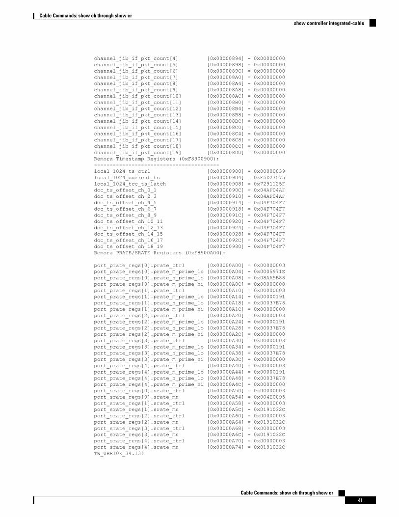
channel_jib_if_pkt_count[4] [0x00000894] = 0x00000000channel_jib_if_pkt_count[5] [0x00000898] = 0x00000000channel_jib_if_pkt_count[6] [0x0000089C] = 0x00000000channel_jib_if_pkt_count[7] [0x000008A0] = 0x00000000channel_jib_if_pkt_count[8] [0x000008A4] = 0x00000000channel_jib_if_pkt_count[9] [0x000008A8] = 0x00000000channel_jib_if_pkt_count[10] [0x000008AC] = 0x00000000channel_jib_if_pkt_count[11] [0x000008B0] = 0x00000000channel_jib_if_pkt_count[12] [0x000008B4] = 0x00000000channel_jib_if_pkt_count[13] [0x000008B8] = 0x00000000channel_jib_if_pkt_count[14] [0x000008BC] = 0x00000000channel_jib_if_pkt_count[15] [0x000008C0] = 0x00000000channel_jib_if_pkt_count[16] [0x000008C4] = 0x00000000channel_jib_if_pkt_count[17] [0x000008C8] = 0x00000000channel_jib_if_pkt_count[18] [0x000008CC] = 0x00000000channel_jib_if_pkt_count[19] [0x000008D0] = 0x00000000Remora Timestamp Registers (0xF8900900):----------------------------------------local_1024_ts_ctrl [0x00000900] = 0x00000039local_1024_current_ts [0x00000904] = 0xF5D27575local_1024_tcc_ts_latch [0x00000908] = 0x7291125Fdoc_ts_offset_ch_0_1 [0x0000090C] = 0x04AF04AFdoc_ts_offset_ch_2_3 [0x00000910] = 0x04AF04AFdoc_ts_offset_ch_4_5 [0x00000914] = 0x04F704F7doc_ts_offset_ch_6_7 [0x00000918] = 0x04F704F7doc_ts_offset_ch_8_9 [0x0000091C] = 0x04F704F7doc_ts_offset_ch_10_11 [0x00000920] = 0x04F704F7doc_ts_offset_ch_12_13 [0x00000924] = 0x04F704F7doc_ts_offset_ch_14_15 [0x00000928] = 0x04F704F7doc_ts_offset_ch_16_17 [0x0000092C] = 0x04F704F7doc_ts_offset_ch_18_19 [0x00000930] = 0x04F704F7Remora PRATE/SRATE Registers (0xF8900A00):------------------------------------------port_prate_regs[0].prate_ctrl [0x00000A00] = 0x00000003port_prate_regs[0].prate_m_prime_lo [0x00000A04] = 0x0005971Eport_prate_regs[0].prate_n_prime_lo [0x00000A08] = 0x08AA5B88port_prate_regs[0].prate_m_prime_hi [0x00000A0C] = 0x00000000port_prate_regs[1].prate_ctrl [0x00000A10] = 0x00000003port_prate_regs[1].prate_m_prime_lo [0x00000A14] = 0x00000191port_prate_regs[1].prate_n_prime_lo [0x00000A18] = 0x00037E78port_prate_regs[1].prate_m_prime_hi [0x00000A1C] = 0x00000000port_prate_regs[2].prate_ctrl [0x00000A20] = 0x00000003port_prate_regs[2].prate_m_prime_lo [0x00000A24] = 0x00000191port_prate_regs[2].prate_n_prime_lo [0x00000A28] = 0x00037E78port_prate_regs[2].prate_m_prime_hi [0x00000A2C] = 0x00000000port_prate_regs[3].prate_ctrl [0x00000A30] = 0x00000003port_prate_regs[3].prate_m_prime_lo [0x00000A34] = 0x00000191port_prate_regs[3].prate_n_prime_lo [0x00000A38] = 0x00037E78port_prate_regs[3].prate_m_prime_hi [0x00000A3C] = 0x00000000port_prate_regs[4].prate_ctrl [0x00000A40] = 0x00000003port_prate_regs[4].prate_m_prime_lo [0x00000A44] = 0x00000191port_prate_regs[4].prate_n_prime_lo [0x00000A48] = 0x00037E78port_prate_regs[4].prate_m_prime_hi [0x00000A4C] = 0x00000000port_srate_regs[0].srate_ctrl [0x00000A50] = 0x00000003port_srate_regs[0].srate_mn [0x00000A54] = 0x004E0095port_srate_regs[1].srate_ctrl [0x00000A58] = 0x00000003port_srate_regs[1].srate_mn [0x00000A5C] = 0x0191032Cport_srate_regs[2].srate_ctrl [0x00000A60] = 0x00000003port_srate_regs[2].srate_mn [0x00000A64] = 0x0191032Cport_srate_regs[3].srate_ctrl [0x00000A68] = 0x00000003port_srate_regs[3].srate_mn [0x00000A6C] = 0x0191032Cport_srate_regs[4].srate_ctrl [0x00000A70] = 0x00000003port_srate_regs[4].srate_mn [0x00000A74] = 0x0191032CTW_UBR10k_34.13#
Cable Commands: show ch through show cr41
Cable Commands: show ch through show crshow controller integrated-cable
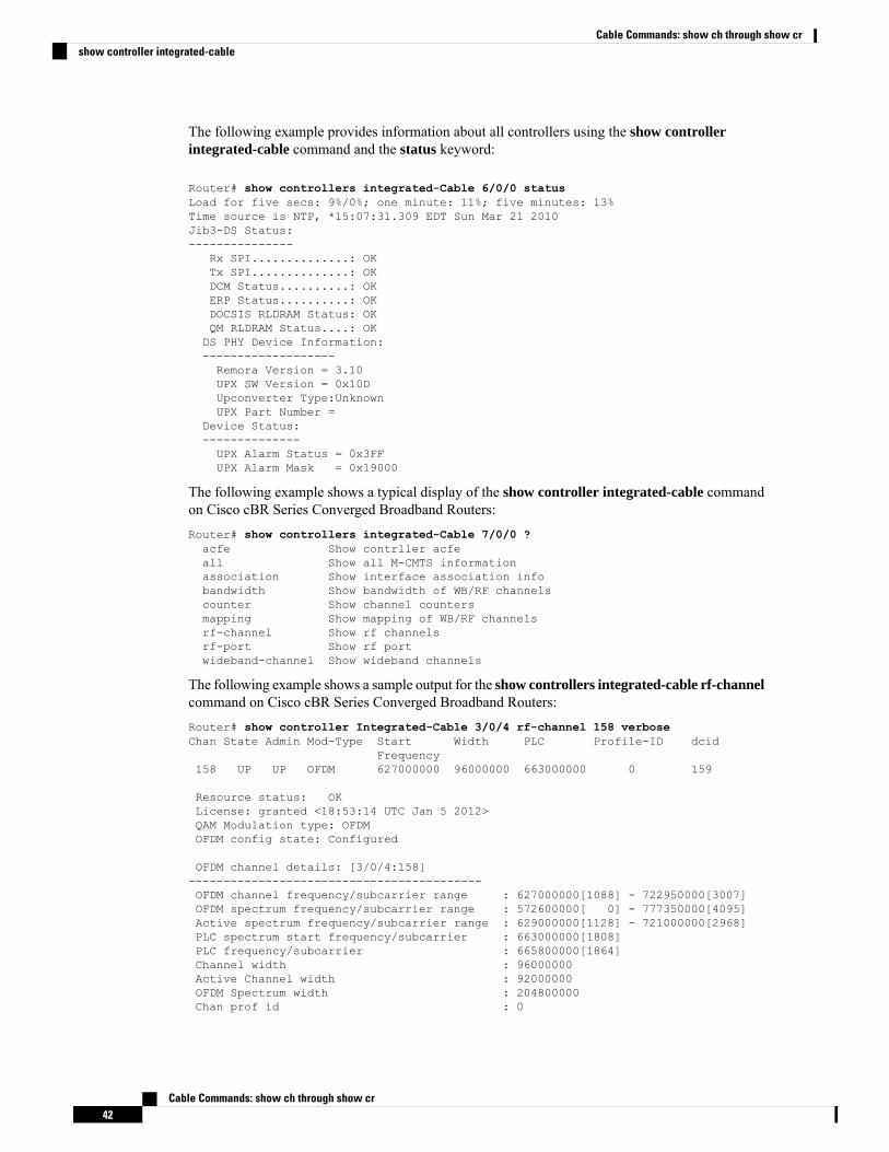
The following example provides information about all controllers using the show controllerintegrated-cable command and the status keyword:
Router# show controllers integrated-Cable 6/0/0 statusLoad for five secs: 9%/0%; one minute: 11%; five minutes: 13%Time source is NTP, *15:07:31.309 EDT Sun Mar 21 2010Jib3-DS Status:---------------
Rx SPI..............: OKTx SPI..............: OKDCM Status..........: OKERP Status..........: OKDOCSIS RLDRAM Status: OKQM RLDRAM Status....: OKDS PHY Device Information:-------------------Remora Version = 3.10UPX SW Version = 0x10DUpconverter Type:UnknownUPX Part Number =
Device Status:--------------UPX Alarm Status = 0x3FFUPX Alarm Mask = 0x19000
The following example shows a typical display of the show controller integrated-cable commandon Cisco cBR Series Converged Broadband Routers:Router# show controllers integrated-Cable 7/0/0 ?acfe Show contrller acfeall Show all M-CMTS informationassociation Show interface association infobandwidth Show bandwidth of WB/RF channelscounter Show channel countersmapping Show mapping of WB/RF channelsrf-channel Show rf channelsrf-port Show rf portwideband-channel Show wideband channels
The following example shows a sample output for the show controllers integrated-cable rf-channelcommand on Cisco cBR Series Converged Broadband Routers:Router# show controller Integrated-Cable 3/0/4 rf-channel 158 verboseChan State Admin Mod-Type Start Width PLC Profile-ID dcid
Frequency158 UP UP OFDM 627000000 96000000 663000000 0 159
Resource status: OKLicense: granted <18:53:14 UTC Jan 5 2012>QAM Modulation type: OFDMOFDM config state: Configured
OFDM channel details: [3/0/4:158]------------------------------------------OFDM channel frequency/subcarrier range : 627000000[1088] - 722950000[3007]OFDM spectrum frequency/subcarrier range : 572600000[ 0] - 777350000[4095]Active spectrum frequency/subcarrier range : 629000000[1128] - 721000000[2968]PLC spectrum start frequency/subcarrier : 663000000[1808]PLC frequency/subcarrier : 665800000[1864]Channel width : 96000000Active Channel width : 92000000OFDM Spectrum width : 204800000Chan prof id : 0
Cable Commands: show ch through show cr42
Cable Commands: show ch through show crshow controller integrated-cable
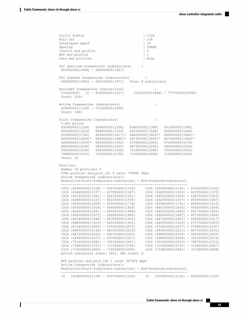
Cyclic Prefix : 1024Roll off : 128Interleave depth : 16Spacing : 50KHZControl mod profile : 0NCP mod profile : 1Data mod profiles : None
PLC spectrum frequencies [subcarriers] :663000000[1808] - 668950000[1927]
PLC channel frequencies [subcarriers] :665800000[1864] - 666150000[1871] Size: 8 subcarriers
Excluded frequencies [subcarriers] :572600000[ 0] - 628950000[1127] 721050000[2969] - 777350000[4095]Count: 2255
Active frequencies [subcarriers] :629000000[1128] - 721000000[2968]Count: 1841
Pilot frequencies [subcarriers] :*:PLC pilots630800000[1164] 634400000[1236] 638000000[1308] 641600000[1380]645200000[1452] 648800000[1524] 652400000[1596] 656000000[1668]659600000[1740] 663450000[1817]* 664050000[1829]* 664600000[1840]*665050000[1849]* 666900000[1886]* 667350000[1895]* 667900000[1906]*668500000[1918]* 669200000[1932] 672800000[2004] 676400000[2076]680000000[2148] 683600000[2220] 687200000[2292] 690800000[2364]694400000[2436] 698000000[2508] 701600000[2580] 705200000[2652]708800000[2724] 712400000[2796] 716000000[2868] 719600000[2940]Count: 32
Profiles:Number of profiles: 2CTRL profile: mod_prof_id: 0 rate: 769861 kbpsActive frequencies [subcarriers]:Modulation:Start-freq[start-subcarrier] - End-freq[end-subcarrier]------------------------------------------------------------------1024 :629000000[1128] - 630750000[1163] 1024 :630850000[1165] - 634350000[1235]1024 :634450000[1237] - 637950000[1307] 1024 :638050000[1309] - 641550000[1379]1024 :641650000[1381] - 645150000[1451] 1024 :645250000[1453] - 648750000[1523]1024 :648850000[1525] - 652350000[1595] 1024 :652450000[1597] - 655950000[1667]1024 :656050000[1669] - 659550000[1739] 1024 :659650000[1741] - 663400000[1816]1024 :663500000[1818] - 664000000[1828] 1024 :664100000[1830] - 664550000[1839]1024 :664650000[1841] - 665000000[1848] 1024 :665100000[1850] - 665750000[1863]1024 :666200000[1872] - 666850000[1885] 1024 :666950000[1887] - 667300000[1894]1024 :667400000[1896] - 667850000[1905] 1024 :667950000[1907] - 668450000[1917]1024 :668550000[1919] - 669150000[1931] 1024 :669250000[1933] - 672750000[2003]1024 :672850000[2005] - 676350000[2075] 1024 :676450000[2077] - 679950000[2147]1024 :680050000[2149] - 683550000[2219] 1024 :683650000[2221] - 687150000[2291]1024 :687250000[2293] - 690750000[2363] 1024 :690850000[2365] - 694350000[2435]1024 :694450000[2437] - 697950000[2507] 1024 :698050000[2509] - 701550000[2579]1024 :701650000[2581] - 705150000[2651] 1024 :705250000[2653] - 708750000[2723]1024 :708850000[2725] - 712350000[2795] 1024 :712450000[2797] - 715950000[2867]1024 :716050000[2869] - 719550000[2939] 1024 :719650000[2941] - 721000000[2968]Active subcarrier count: 1801, ZBL count: 0
NCP profile: mod_prof_id: 1 rate: 307944 kbpsActive frequencies [subcarriers]:Modulation:Start-freq[start-subcarrier] - End-freq[end-subcarrier]------------------------------------------------------------------16 :629000000[1128] - 630750000[1163] 16 :630850000[1165] - 634350000[1235]
Cable Commands: show ch through show cr43
Cable Commands: show ch through show crshow controller integrated-cable
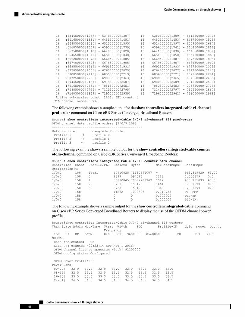
16 :634450000[1237] - 637950000[1307] 16 :638050000[1309] - 641550000[1379]16 :641650000[1381] - 645150000[1451] 16 :645250000[1453] - 648750000[1523]16 :648850000[1525] - 652350000[1595] 16 :652450000[1597] - 655950000[1667]16 :656050000[1669] - 659550000[1739] 16 :659650000[1741] - 663400000[1816]16 :663500000[1818] - 664000000[1828] 16 :664100000[1830] - 664550000[1839]16 :664650000[1841] - 665000000[1848] 16 :665100000[1850] - 665750000[1863]16 :666200000[1872] - 666850000[1885] 16 :666950000[1887] - 667300000[1894]16 :667400000[1896] - 667850000[1905] 16 :667950000[1907] - 668450000[1917]16 :668550000[1919] - 669150000[1931] 16 :669250000[1933] - 672750000[2003]16 :672850000[2005] - 676350000[2075] 16 :676450000[2077] - 679950000[2147]16 :680050000[2149] - 683550000[2219] 16 :683650000[2221] - 687150000[2291]16 :687250000[2293] - 690750000[2363] 16 :690850000[2365] - 694350000[2435]16 :694450000[2437] - 697950000[2507] 16 :698050000[2509] - 701550000[2579]16 :701650000[2581] - 705150000[2651] 16 :705250000[2653] - 708750000[2723]16 :708850000[2725] - 712350000[2795] 16 :712450000[2797] - 715950000[2867]16 :716050000[2869] - 719550000[2939] 16 :719650000[2941] - 721000000[2968]Active subcarrier count: 1801, ZBL count: 0JIB channel number: 776
The following example shows a sample output for the show controllers integrated-cable rf-channelprof-order command on Cisco cBR Series Converged Broadband Routers:Router# show controllers integrated-Cable 2/0/3 rf-channel 158 prof-orderOFDM channel data profile order: [2/0/3:158]-----------------------------------------------Data Profile: Downgrade Profile:Profile 1 -> Profile 0Profile 2 -> Profile 1Profile 3 -> Profile 2
The following example shows a sample output for the show controllers integrated-cable counterofdm-channel command on Cisco cBR Series Converged Broadband Routers:Router# show controllers integrated-Cable 1/0/0 counter ofdm-channelController Chan# Profile/PLC Packets Bytes MaxRate(Mbps) Rate(Mbps)Utilization(%)1/0/0 158 Total 50910825 71180994007 - 953.319829 63.001/0/0 158 0 9389 597096 1216 0.006359 0.01/0/0 158 1 50880045 70579288749 1512 953.251033 63.01/0/0 158 2 3753 150120 1664 0.001599 0.01/0/0 158 3 3753 150120 1360 0.001599 0.01/0/0 158 11262 1009826 0.010758 PLC-MMM1/0/0 158 0 0 0.000000 PLC-EM1/0/0 158 0 0 0.000000 PLC-TR
The following example shows a sample output for the show controllers integrated-cable commandon Cisco cBR Series Converged Broadband Routers to display the use of the OFDM channel powerprofile.Router#show controller Integrated-Cable 3/0/0 rf-channel 158 verboseChan State Admin Mod-Type Start Width PLC Profile-ID dcid power output
Frequency158 UP UP OFDM 849000000 96000000 856000000 20 159 33.0NORMALResource status: OKLicense: granted <09:23:14 EDT Aug 1 2016>OFDM channel license spectrum width: 92200000OFDM config state: Configured
OFDM Power Profile: 3Power-Band:[00-07] 32.0 32.0 32.0 32.0 32.0 32.0 32.0 32.0[08-15] 32.5 32.5 32.5 32.5 32.5 32.5 32.5 32.5[16-23] 33.5 33.5 33.5 33.5 33.5 33.5 33.5 33.5[24-31] 34.5 34.5 34.5 34.5 34.5 34.5 34.5 34.5
Cable Commands: show ch through show cr44
Cable Commands: show ch through show crshow controller integrated-cable
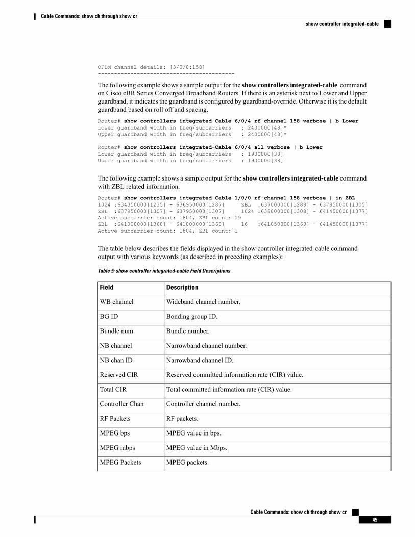
OFDM channel details: [3/0/0:158]------------------------------------------
The following example shows a sample output for the show controllers integrated-cable commandon Cisco cBR Series Converged Broadband Routers. If there is an asterisk next to Lower and Upperguardband, it indicates the guardband is configured by guardband-override. Otherwise it is the defaultguardband based on roll off and spacing.Router# show controllers integrated-Cable 6/0/4 rf-channel 158 verbose | b LowerLower guardband width in freq/subcarriers : 2400000[48]*Upper guardband width in freq/subcarriers : 2400000[48]*
Router# show controllers integrated-Cable 6/0/4 all verbose | b LowerLower guardband width in freq/subcarriers : 1900000[38]Upper guardband width in freq/subcarriers : 1900000[38]
The following example shows a sample output for the show controllers integrated-cable commandwith ZBL related information.Router# show controllers integrated-Cable 1/0/0 rf-channel 158 verbose | in ZBL1024 :634350000[1235] - 636950000[1287] ZBL :637000000[1288] - 637850000[1305]ZBL :637950000[1307] - 637950000[1307] 1024 :638000000[1308] - 641450000[1377]Active subcarrier count: 1804, ZBL count: 19ZBL :641000000[1368] - 641000000[1368] 16 :641050000[1369] - 641450000[1377]Active subcarrier count: 1804, ZBL count: 1
The table below describes the fields displayed in the show controller integrated-cable commandoutput with various keywords (as described in preceding examples):
Table 5: show controller integrated-cable Field Descriptions
DescriptionField
Wideband channel number.WB channel
Bonding group ID.BG ID
Bundle number.Bundle num
Narrowband channel number.NB channel
Narrowband channel ID.NB chan ID
Reserved committed information rate (CIR) value.Reserved CIR
Total committed information rate (CIR) value.Total CIR
Controller channel number.Controller Chan
RF packets.RF Packets
MPEG value in bps.MPEG bps
MPEG value in Mbps.MPEG mbps
MPEG packets.MPEG Packets
Cable Commands: show ch through show cr45
Cable Commands: show ch through show crshow controller integrated-cable
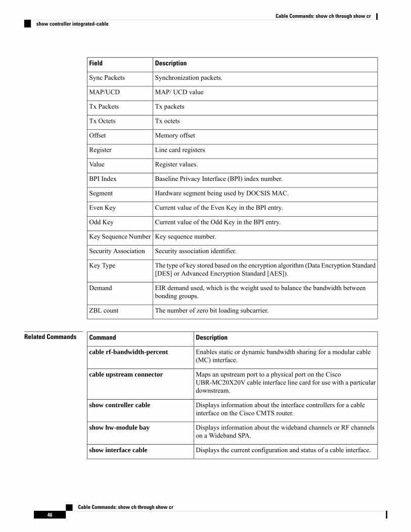
DescriptionField
Synchronization packets.Sync Packets
MAP/ UCD valueMAP/UCD
Tx packetsTx Packets
Tx octetsTx Octets
Memory offsetOffset
Line card registersRegister
Register values.Value
Baseline Privacy Interface (BPI) index number.BPI Index
Hardware segment being used by DOCSIS MAC.Segment
Current value of the Even Key in the BPI entry.Even Key
Current value of the Odd Key in the BPI entry.Odd Key
Key sequence number.Key Sequence Number
Security association identifier.Security Association
The type of key stored based on the encryption algorithm (Data Encryption Standard[DES] or Advanced Encryption Standard [AES]).
Key Type
EIR demand used, which is the weight used to balance the bandwidth betweenbonding groups.
Demand
The number of zero bit loading subcarrier.ZBL count
Related Commands DescriptionCommand
Enables static or dynamic bandwidth sharing for a modular cable(MC) interface.
cable rf-bandwidth-percent
Maps an upstream port to a physical port on the CiscoUBR-MC20X20V cable interface line card for use with a particulardownstream.
cable upstream connector
Displays information about the interface controllers for a cableinterface on the Cisco CMTS router.
show controller cable
Displays information about the wideband channels or RF channelson a Wideband SPA.
show hw-module bay
Displays the current configuration and status of a cable interface.show interface cable
Cable Commands: show ch through show cr46
Cable Commands: show ch through show crshow controller integrated-cable

DescriptionCommand
Displays information about the profiles associated with the cablemodems (CMs).
show cable modem phy ofdm-profile
Displays detailed profile management data associated with eachcable modem.
show cable modem prof-mgmt
Cable Commands: show ch through show cr47
Cable Commands: show ch through show crshow controller integrated-cable
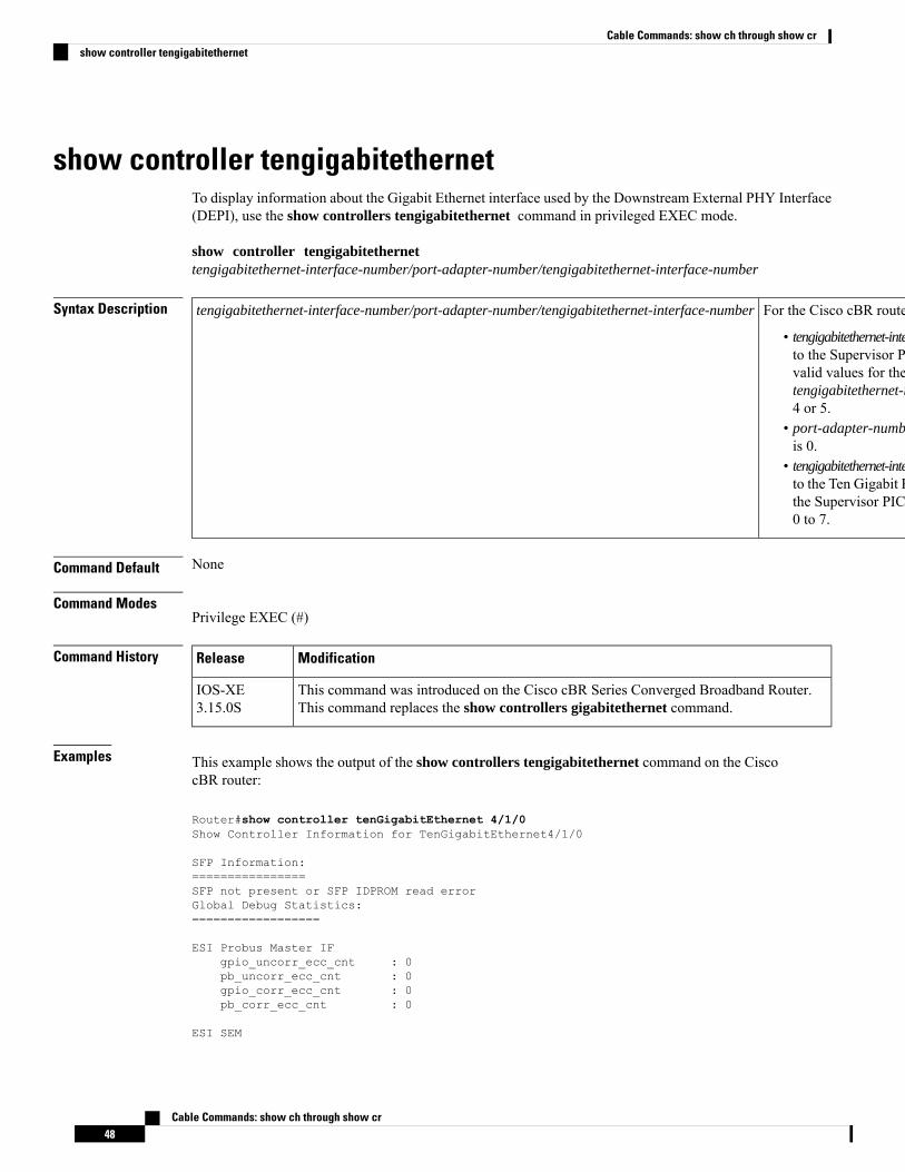
show controller tengigabitethernetTo display information about the Gigabit Ethernet interface used by the Downstream External PHY Interface(DEPI), use the show controllers tengigabitethernet command in privileged EXEC mode.
show controller tengigabitethernettengigabitethernet-interface-number/port-adapter-number/tengigabitethernet-interface-number
Syntax Description For the Cisco cBR router—
• tengigabitethernet-interface-number—Refersto the Supervisor PIC slot number. Thevalid values for thetengigabitethernet-interface-number are4 or 5.
• port-adapter-number—The valid valueis 0.
• tengigabitethernet-interface-number—Refersto the Ten Gigabit Ethernet interface onthe Supervisor PIC. The valid range is0 to 7.
tengigabitethernet-interface-number/port-adapter-number/tengigabitethernet-interface-number
Command Default None
Command ModesPrivilege EXEC (#)
Command History ModificationRelease
This command was introduced on the Cisco cBR Series Converged Broadband Router.This command replaces the show controllers gigabitethernet command.
IOS-XE3.15.0S
Examples This example shows the output of the show controllers tengigabitethernet command on the CiscocBR router:
Router#show controller tenGigabitEthernet 4/1/0Show Controller Information for TenGigabitEthernet4/1/0
SFP Information:================SFP not present or SFP IDPROM read errorGlobal Debug Statistics:==================
ESI Probus Master IFgpio_uncorr_ecc_cnt : 0pb_uncorr_ecc_cnt : 0gpio_corr_ecc_cnt : 0pb_corr_ecc_cnt : 0
ESI SEM
Cable Commands: show ch through show cr48
Cable Commands: show ch through show crshow controller tengigabitethernet
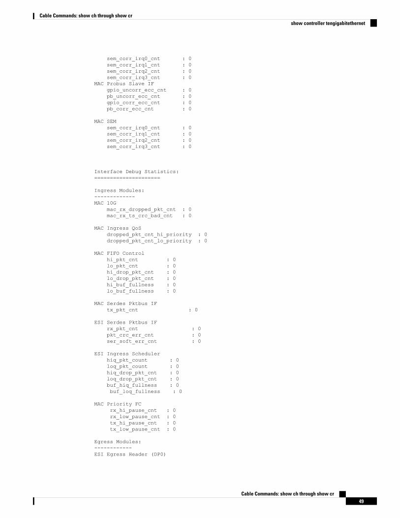
sem_corr_irq0_cnt : 0sem_corr_irq1_cnt : 0sem_corr_irq2_cnt : 0sem_corr_irq3_cnt : 0
MAC Probus Slave IFgpio_uncorr_ecc_cnt : 0pb_uncorr_ecc_cnt : 0gpio_corr_ecc_cnt : 0pb_corr_ecc_cnt : 0
MAC SEMsem_corr_irq0_cnt : 0sem_corr_irq1_cnt : 0sem_corr_irq2_cnt : 0sem_corr_irq3_cnt : 0
Interface Debug Statistics:=====================
Ingress Modules:-------------MAC 10G
mac_rx_dropped_pkt_cnt : 0mac_rx_ts_crc_bad_cnt : 0
MAC Ingress QoSdropped_pkt_cnt_hi_priority : 0dropped_pkt_cnt_lo_priority : 0
MAC FIFO Controlhi_pkt_cnt : 0lo_pkt_cnt : 0hi_drop_pkt_cnt : 0lo_drop_pkt_cnt : 0hi_buf_fullness : 0lo_buf_fullness : 0
MAC Serdes Pktbus IFtx_pkt_cnt : 0
ESI Serdes Pktbus IFrx_pkt_cnt : 0pkt_crc_err_cnt : 0ser_soft_err_cnt : 0
ESI Ingress Schedulerhiq_pkt_count : 0loq_pkt_count : 0hiq_drop_pkt_cnt : 0loq_drop_pkt_cnt : 0buf_hiq_fullness : 0buf_loq_fullness : 0
MAC Priority FCrx_hi_pause_cnt : 0rx_low_pause_cnt : 0tx_hi_pause_cnt : 0tx_low_pause_cnt : 0
Egress Modules:------------ESI Egress Header (DP0)
Cable Commands: show ch through show cr49
Cable Commands: show ch through show crshow controller tengigabitethernet
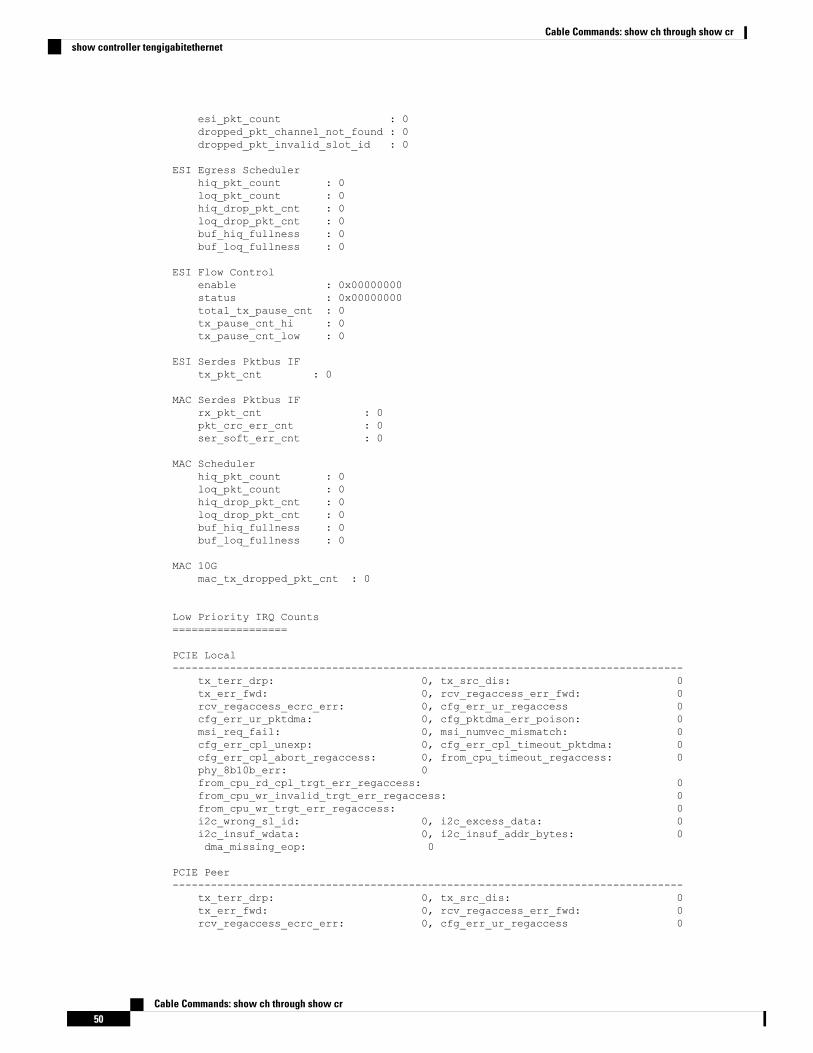
esi_pkt_count : 0dropped_pkt_channel_not_found : 0dropped_pkt_invalid_slot_id : 0
ESI Egress Schedulerhiq_pkt_count : 0loq_pkt_count : 0hiq_drop_pkt_cnt : 0loq_drop_pkt_cnt : 0buf_hiq_fullness : 0buf_loq_fullness : 0
ESI Flow Controlenable : 0x00000000status : 0x00000000total_tx_pause_cnt : 0tx_pause_cnt_hi : 0tx_pause_cnt_low : 0
ESI Serdes Pktbus IFtx_pkt_cnt : 0
MAC Serdes Pktbus IFrx_pkt_cnt : 0pkt_crc_err_cnt : 0ser_soft_err_cnt : 0
MAC Schedulerhiq_pkt_count : 0loq_pkt_count : 0hiq_drop_pkt_cnt : 0loq_drop_pkt_cnt : 0buf_hiq_fullness : 0buf_loq_fullness : 0
MAC 10Gmac_tx_dropped_pkt_cnt : 0
Low Priority IRQ Counts==================
PCIE Local--------------------------------------------------------------------------------
tx_terr_drp: 0, tx_src_dis: 0tx_err_fwd: 0, rcv_regaccess_err_fwd: 0rcv_regaccess_ecrc_err: 0, cfg_err_ur_regaccess 0cfg_err_ur_pktdma: 0, cfg_pktdma_err_poison: 0msi_req_fail: 0, msi_numvec_mismatch: 0cfg_err_cpl_unexp: 0, cfg_err_cpl_timeout_pktdma: 0cfg_err_cpl_abort_regaccess: 0, from_cpu_timeout_regaccess: 0phy_8b10b_err: 0from_cpu_rd_cpl_trgt_err_regaccess: 0from_cpu_wr_invalid_trgt_err_regaccess: 0from_cpu_wr_trgt_err_regaccess: 0i2c_wrong_sl_id: 0, i2c_excess_data: 0i2c_insuf_wdata: 0, i2c_insuf_addr_bytes: 0dma_missing_eop: 0
PCIE Peer--------------------------------------------------------------------------------
tx_terr_drp: 0, tx_src_dis: 0tx_err_fwd: 0, rcv_regaccess_err_fwd: 0rcv_regaccess_ecrc_err: 0, cfg_err_ur_regaccess 0
Cable Commands: show ch through show cr50
Cable Commands: show ch through show crshow controller tengigabitethernet
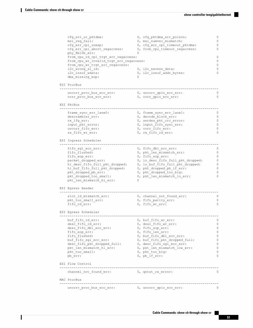
cfg_err_ur_pktdma: 0, cfg_pktdma_err_poison: 0msi_req_fail: 0, msi_numvec_mismatch: 0cfg_err_cpl_unexp: 0, cfg_err_cpl_timeout_pktdma: 0cfg_err_cpl_abort_regaccess: 0, from_cpu_timeout_regaccess: 0phy_8b10b_err: 0from_cpu_rd_cpl_trgt_err_regaccess: 0from_cpu_wr_invalid_trgt_err_regaccess: 0from_cpu_wr_trgt_err_regaccess: 0i2c_wrong_sl_id: 0, i2c_excess_data: 0i2c_insuf_wdata: 0, i2c_insuf_addr_bytes: 0dma_missing_eop: 0
ESI ProcBus--------------------------------------------------------------------------------
uncorr_proc_bus_ecc_err: 0, uncorr_gpio_ecc_err: 0corr_proc_bus_ecc_err: 0, corr_gpio_ecc_err: 0
ESI PktBus--------------------------------------------------------------------------------
frame_sync_err_lane0: 0, frame_sync_err_lane1: 0descrambler_err: 0, decode_block_err: 0rx_ifg_err: 0, serdes_pkt_crc_error: 0input_pkt_error: 0, input_fifo_sync_err: 0uncorr_fifo_err: 0, corr_fifo_err: 0rx_fifo_wr_err: 0, rx_fifo_rd_err: 0
ESI Ingress Scheduler--------------------------------------------------------------------------------
fifo_sgl_ecc_err: 0, fifo_dbl_ecc_err: 0fifo_flushed: 0, pkt_len_mismatch_err: 0fifo_eop_err: 0, fifo_sop_err: 0packet_dropped_err: 0, lo_desc_fifo_full_pkt_dropped: 0hi_desc_fifo_full_pkt_dropped: 0, lo_buf_fifo_full_pkt_dropped: 0hi_buf_fifo_full_pkt_dropped: 0, pkt_dropped_pb_if_err: 0pkt_dropped_pb_err: 0, pkt_dropped_too_big: 0pkt_dropped_too_small: 0, pkt_len_mismatch_lo_err: 0pkt_len_mismatch_hi_err: 0
ESI Egress Header--------------------------------------------------------------------------------
slot_id_mismatch_err: 0, channel_not_found_err: 0pkt_too_small_err: 0, fifo_parity_err: 0fifo_rd_err: 0, fifo_wr_err: 0
ESI Egress Scheduler--------------------------------------------------------------------------------
buf_fifo_rd_err: 0, buf_fifo_wr_err: 0desc_fifo_rd_err: 0, desc_fifo_wr_err: 0desc_fifo_dbl_ecc_err: 0, fifo_sop_err: 0fifo_eop_err: 0, fifo_len_err: 0fifo_flushed: 0, buf_fifo_dbl_ecc_err: 0buf_fifo_sgl_ecc_err: 0, buf_fifo_pkt_dropped_full: 0desc_fifo_pkt_dropped_full: 0, desc_fifo_sgl_ecc_err: 0pkt_len_mismatch_hi_err: 0, pkt_len_mismatch_low_err: 0pkt_too_small: 0, pkt_too_big: 0pb_err: 0, pb_if_err: 0
ESI Flow Control--------------------------------------------------------------------------------
channel_not_found_err: 0, qstat_rx_error: 0
MAC ProcBus--------------------------------------------------------------------------------
uncorr_proc_bus_ecc_err: 0, uncorr_gpio_ecc_err: 0
Cable Commands: show ch through show cr51
Cable Commands: show ch through show crshow controller tengigabitethernet
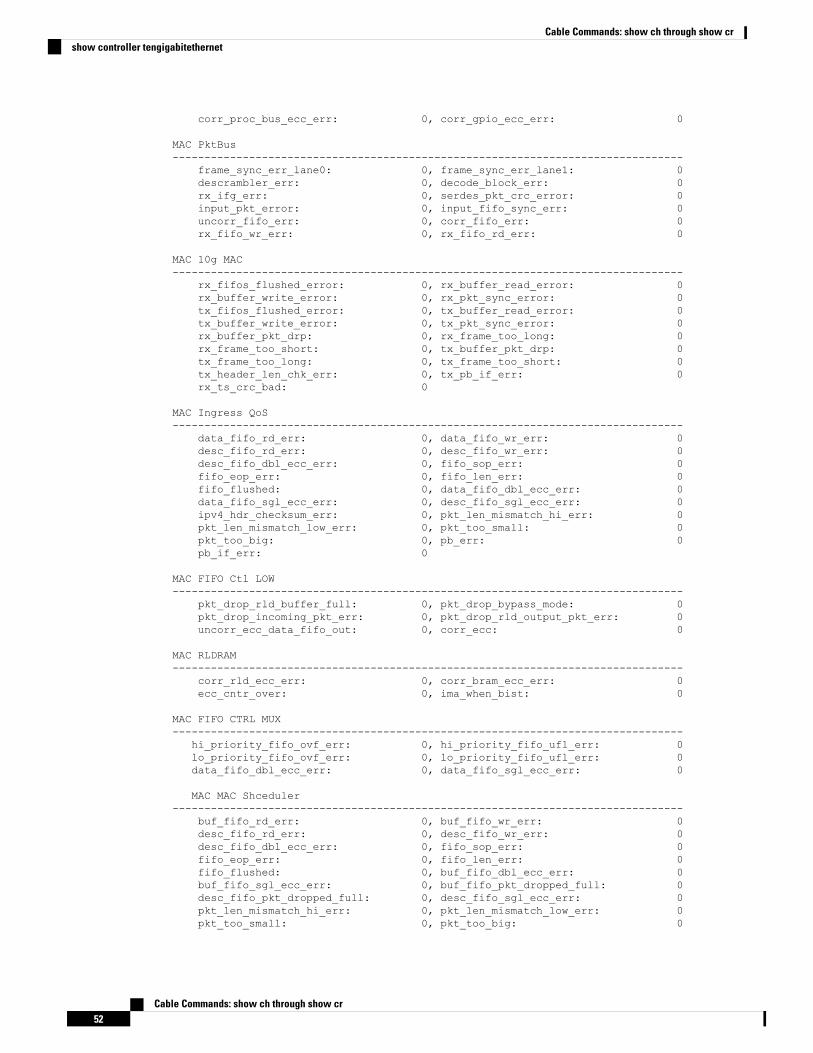
corr_proc_bus_ecc_err: 0, corr_gpio_ecc_err: 0
MAC PktBus--------------------------------------------------------------------------------
frame_sync_err_lane0: 0, frame_sync_err_lane1: 0descrambler_err: 0, decode_block_err: 0rx_ifg_err: 0, serdes_pkt_crc_error: 0input_pkt_error: 0, input_fifo_sync_err: 0uncorr_fifo_err: 0, corr_fifo_err: 0rx_fifo_wr_err: 0, rx_fifo_rd_err: 0
MAC 10g MAC--------------------------------------------------------------------------------
rx_fifos_flushed_error: 0, rx_buffer_read_error: 0rx_buffer_write_error: 0, rx_pkt_sync_error: 0tx_fifos_flushed_error: 0, tx_buffer_read_error: 0tx_buffer_write_error: 0, tx_pkt_sync_error: 0rx_buffer_pkt_drp: 0, rx_frame_too_long: 0rx_frame_too_short: 0, tx_buffer_pkt_drp: 0tx_frame_too_long: 0, tx_frame_too_short: 0tx_header_len_chk_err: 0, tx_pb_if_err: 0rx_ts_crc_bad: 0
MAC Ingress QoS--------------------------------------------------------------------------------
data_fifo_rd_err: 0, data_fifo_wr_err: 0desc_fifo_rd_err: 0, desc_fifo_wr_err: 0desc_fifo_dbl_ecc_err: 0, fifo_sop_err: 0fifo_eop_err: 0, fifo_len_err: 0fifo_flushed: 0, data_fifo_dbl_ecc_err: 0data_fifo_sgl_ecc_err: 0, desc_fifo_sgl_ecc_err: 0ipv4_hdr_checksum_err: 0, pkt_len_mismatch_hi_err: 0pkt_len_mismatch_low_err: 0, pkt_too_small: 0pkt_too_big: 0, pb_err: 0pb_if_err: 0
MAC FIFO Ctl LOW--------------------------------------------------------------------------------
pkt_drop_rld_buffer_full: 0, pkt_drop_bypass_mode: 0pkt_drop_incoming_pkt_err: 0, pkt_drop_rld_output_pkt_err: 0uncorr_ecc_data_fifo_out: 0, corr_ecc: 0
MAC RLDRAM--------------------------------------------------------------------------------
corr_rld_ecc_err: 0, corr_bram_ecc_err: 0ecc_cntr_over: 0, ima_when_bist: 0
MAC FIFO CTRL MUX--------------------------------------------------------------------------------
hi_priority_fifo_ovf_err: 0, hi_priority_fifo_ufl_err: 0lo_priority_fifo_ovf_err: 0, lo_priority_fifo_ufl_err: 0data_fifo_dbl_ecc_err: 0, data_fifo_sgl_ecc_err: 0
MAC MAC Shceduler--------------------------------------------------------------------------------
buf_fifo_rd_err: 0, buf_fifo_wr_err: 0desc_fifo_rd_err: 0, desc_fifo_wr_err: 0desc_fifo_dbl_ecc_err: 0, fifo_sop_err: 0fifo_eop_err: 0, fifo_len_err: 0fifo_flushed: 0, buf_fifo_dbl_ecc_err: 0buf_fifo_sgl_ecc_err: 0, buf_fifo_pkt_dropped_full: 0desc_fifo_pkt_dropped_full: 0, desc_fifo_sgl_ecc_err: 0pkt_len_mismatch_hi_err: 0, pkt_len_mismatch_low_err: 0pkt_too_small: 0, pkt_too_big: 0
Cable Commands: show ch through show cr52
Cable Commands: show ch through show crshow controller tengigabitethernet
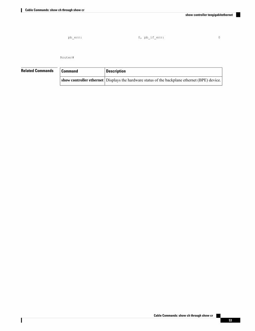
pb_err: 0, pb_if_err: 0
Router#
Related Commands DescriptionCommand
Displays the hardware status of the backplane ethernet (BPE) device.show controller ethernet
Cable Commands: show ch through show cr53
Cable Commands: show ch through show crshow controller tengigabitethernet
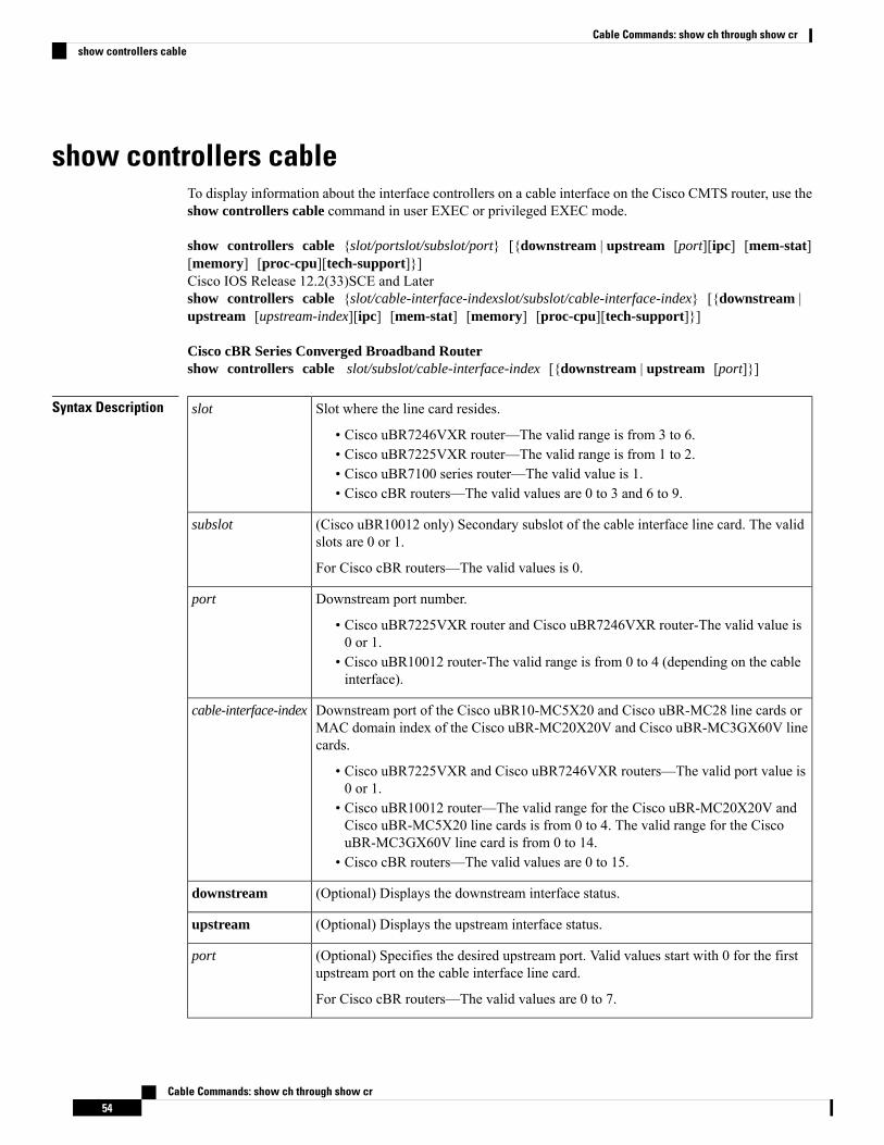
show controllers cableTo display information about the interface controllers on a cable interface on the Cisco CMTS router, use theshow controllers cable command in user EXEC or privileged EXEC mode.
show controllers cable {slot/portslot/subslot/port} [{downstream | upstream [port][ipc] [mem-stat][memory] [proc-cpu][tech-support]}]Cisco IOS Release 12.2(33)SCE and Latershow controllers cable {slot/cable-interface-indexslot/subslot/cable-interface-index} [{downstream |upstream [upstream-index][ipc] [mem-stat] [memory] [proc-cpu][tech-support]}]
Cisco cBR Series Converged Broadband Routershow controllers cable slot/subslot/cable-interface-index [{downstream | upstream [port]}]
Syntax Description Slot where the line card resides.
• Cisco uBR7246VXR router—The valid range is from 3 to 6.• Cisco uBR7225VXR router—The valid range is from 1 to 2.• Cisco uBR7100 series router—The valid value is 1.• Cisco cBR routers—The valid values are 0 to 3 and 6 to 9.
slot
(Cisco uBR10012 only) Secondary subslot of the cable interface line card. The validslots are 0 or 1.
For Cisco cBR routers—The valid values is 0.
subslot
Downstream port number.
• Cisco uBR7225VXR router and Cisco uBR7246VXR router-The valid value is0 or 1.
• Cisco uBR10012 router-The valid range is from 0 to 4 (depending on the cableinterface).
port
Downstream port of the Cisco uBR10-MC5X20 and Cisco uBR-MC28 line cards orMAC domain index of the Cisco uBR-MC20X20V and Cisco uBR-MC3GX60V linecards.
• Cisco uBR7225VXR and Cisco uBR7246VXR routers—The valid port value is0 or 1.
• Cisco uBR10012 router—The valid range for the Cisco uBR-MC20X20V andCisco uBR-MC5X20 line cards is from 0 to 4. The valid range for the CiscouBR-MC3GX60V line card is from 0 to 14.
• Cisco cBR routers—The valid values are 0 to 15.
cable-interface-index
(Optional) Displays the downstream interface status.downstream
(Optional) Displays the upstream interface status.upstream
(Optional) Specifies the desired upstream port. Valid values start with 0 for the firstupstream port on the cable interface line card.
For Cisco cBR routers—The valid values are 0 to 7.
port
Cable Commands: show ch through show cr54
Cable Commands: show ch through show crshow controllers cable
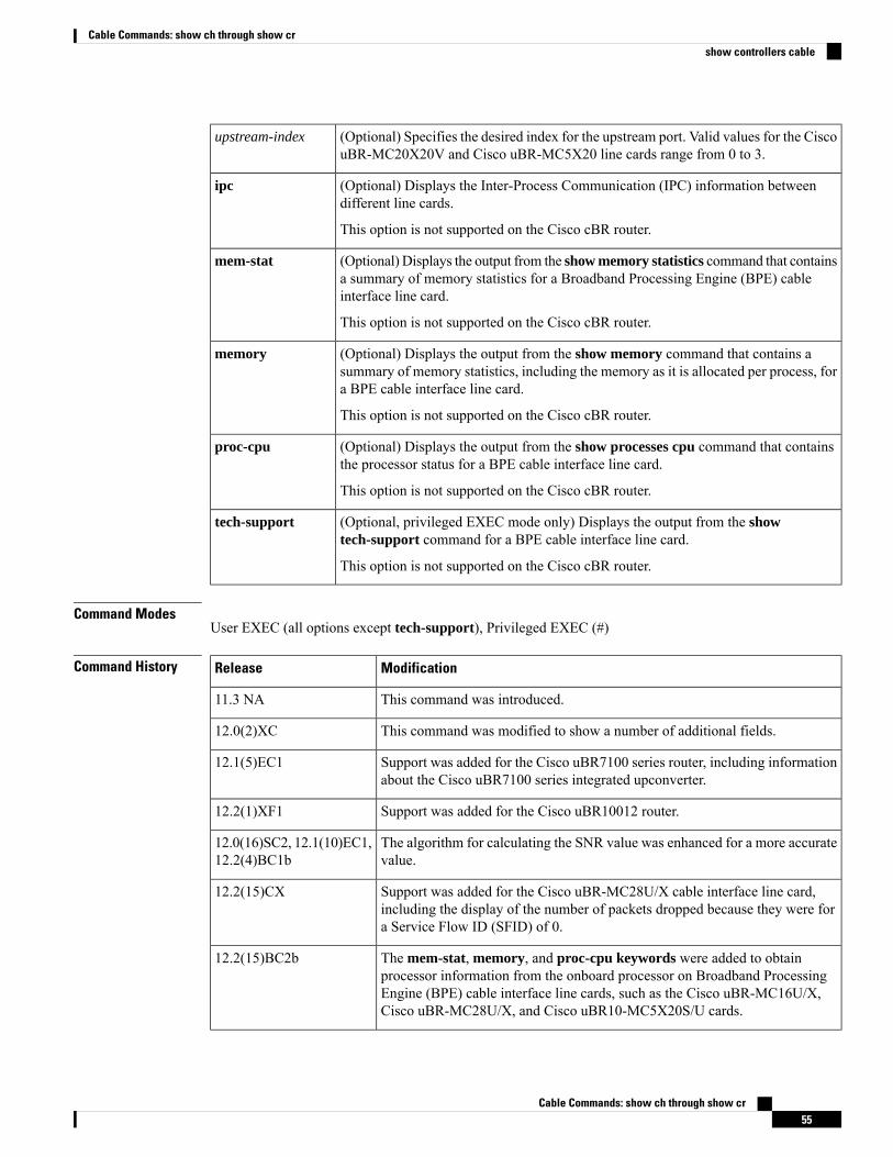
(Optional) Specifies the desired index for the upstream port. Valid values for the CiscouBR-MC20X20V and Cisco uBR-MC5X20 line cards range from 0 to 3.
upstream-index
(Optional) Displays the Inter-Process Communication (IPC) information betweendifferent line cards.
This option is not supported on the Cisco cBR router.
ipc
(Optional) Displays the output from the show memory statistics command that containsa summary of memory statistics for a Broadband Processing Engine (BPE) cableinterface line card.
This option is not supported on the Cisco cBR router.
mem-stat
(Optional) Displays the output from the show memory command that contains asummary of memory statistics, including the memory as it is allocated per process, fora BPE cable interface line card.
This option is not supported on the Cisco cBR router.
memory
(Optional) Displays the output from the show processes cpu command that containsthe processor status for a BPE cable interface line card.
This option is not supported on the Cisco cBR router.
proc-cpu
(Optional, privileged EXEC mode only) Displays the output from the showtech-support command for a BPE cable interface line card.
This option is not supported on the Cisco cBR router.
tech-support
Command ModesUser EXEC (all options except tech-support), Privileged EXEC (#)
Command History ModificationRelease
This command was introduced.11.3 NA
This command was modified to show a number of additional fields.12.0(2)XC
Support was added for the Cisco uBR7100 series router, including informationabout the Cisco uBR7100 series integrated upconverter.
12.1(5)EC1
Support was added for the Cisco uBR10012 router.12.2(1)XF1
The algorithm for calculating the SNR value was enhanced for a more accuratevalue.
12.0(16)SC2, 12.1(10)EC1,12.2(4)BC1b
Support was added for the Cisco uBR-MC28U/X cable interface line card,including the display of the number of packets dropped because they were fora Service Flow ID (SFID) of 0.
12.2(15)CX
The mem-stat, memory, and proc-cpu keywords were added to obtainprocessor information from the onboard processor on Broadband ProcessingEngine (BPE) cable interface line cards, such as the Cisco uBR-MC16U/X,Cisco uBR-MC28U/X, and Cisco uBR10-MC5X20S/U cards.
12.2(15)BC2b
Cable Commands: show ch through show cr55
Cable Commands: show ch through show crshow controllers cable
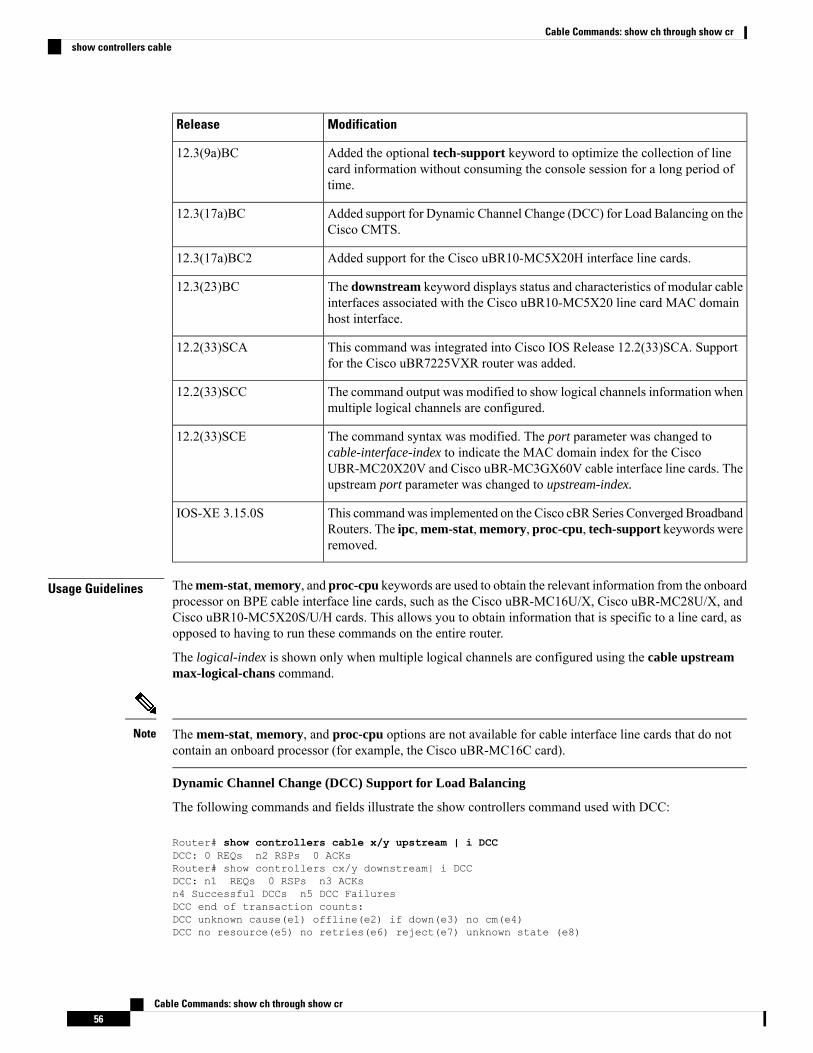
ModificationRelease
Added the optional tech-support keyword to optimize the collection of linecard information without consuming the console session for a long period oftime.
12.3(9a)BC
Added support for Dynamic Channel Change (DCC) for Load Balancing on theCisco CMTS.
12.3(17a)BC
Added support for the Cisco uBR10-MC5X20H interface line cards.12.3(17a)BC2
The downstream keyword displays status and characteristics of modular cableinterfaces associated with the Cisco uBR10-MC5X20 line card MAC domainhost interface.
12.3(23)BC
This command was integrated into Cisco IOS Release 12.2(33)SCA. Supportfor the Cisco uBR7225VXR router was added.
12.2(33)SCA
The command output was modified to show logical channels information whenmultiple logical channels are configured.
12.2(33)SCC
The command syntax was modified. The port parameter was changed tocable-interface-index to indicate the MAC domain index for the CiscoUBR-MC20X20V and Cisco uBR-MC3GX60V cable interface line cards. Theupstream port parameter was changed to upstream-index.
12.2(33)SCE
This commandwas implemented on the Cisco cBRSeries Converged BroadbandRouters. The ipc,mem-stat,memory, proc-cpu, tech-support keywords wereremoved.
IOS-XE 3.15.0S
Usage Guidelines Themem-stat,memory, and proc-cpu keywords are used to obtain the relevant information from the onboardprocessor on BPE cable interface line cards, such as the Cisco uBR-MC16U/X, Cisco uBR-MC28U/X, andCisco uBR10-MC5X20S/U/H cards. This allows you to obtain information that is specific to a line card, asopposed to having to run these commands on the entire router.
The logical-index is shown only when multiple logical channels are configured using the cable upstreammax-logical-chans command.
The mem-stat, memory, and proc-cpu options are not available for cable interface line cards that do notcontain an onboard processor (for example, the Cisco uBR-MC16C card).
Note
Dynamic Channel Change (DCC) Support for Load Balancing
The following commands and fields illustrate the show controllers command used with DCC:
Router# show controllers cable x/y upstream | i DCCDCC: 0 REQs n2 RSPs 0 ACKsRouter# show controllers cx/y downstream| i DCCDCC: n1 REQs 0 RSPs n3 ACKsn4 Successful DCCs n5 DCC FailuresDCC end of transaction counts:DCC unknown cause(e1) offline(e2) if down(e3) no cm(e4)DCC no resource(e5) no retries(e6) reject(e7) unknown state (e8)
Cable Commands: show ch through show cr56
Cable Commands: show ch through show crshow controllers cable
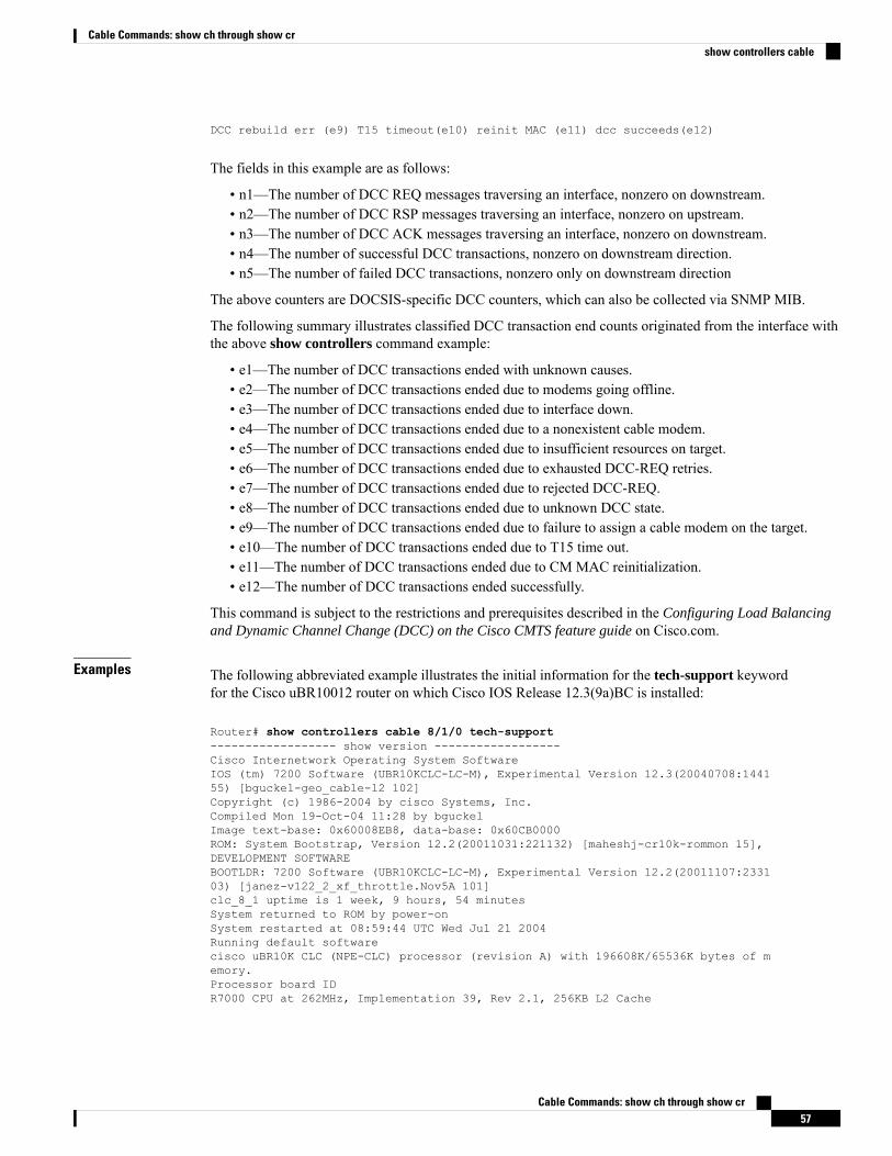
DCC rebuild err (e9) T15 timeout(e10) reinit MAC (e11) dcc succeeds(e12)
The fields in this example are as follows:
• n1—The number of DCC REQ messages traversing an interface, nonzero on downstream.• n2—The number of DCC RSP messages traversing an interface, nonzero on upstream.• n3—The number of DCC ACK messages traversing an interface, nonzero on downstream.• n4—The number of successful DCC transactions, nonzero on downstream direction.• n5—The number of failed DCC transactions, nonzero only on downstream direction
The above counters are DOCSIS-specific DCC counters, which can also be collected via SNMP MIB.
The following summary illustrates classified DCC transaction end counts originated from the interface withthe above show controllers command example:
• e1—The number of DCC transactions ended with unknown causes.• e2—The number of DCC transactions ended due to modems going offline.• e3—The number of DCC transactions ended due to interface down.• e4—The number of DCC transactions ended due to a nonexistent cable modem.• e5—The number of DCC transactions ended due to insufficient resources on target.• e6—The number of DCC transactions ended due to exhausted DCC-REQ retries.• e7—The number of DCC transactions ended due to rejected DCC-REQ.• e8—The number of DCC transactions ended due to unknown DCC state.• e9—The number of DCC transactions ended due to failure to assign a cable modem on the target.• e10—The number of DCC transactions ended due to T15 time out.• e11—The number of DCC transactions ended due to CM MAC reinitialization.• e12—The number of DCC transactions ended successfully.
This command is subject to the restrictions and prerequisites described in the Configuring Load Balancingand Dynamic Channel Change (DCC) on the Cisco CMTS feature guide on Cisco.com.
Examples The following abbreviated example illustrates the initial information for the tech-support keywordfor the Cisco uBR10012 router on which Cisco IOS Release 12.3(9a)BC is installed:
Router# show controllers cable 8/1/0 tech-support------------------ show version ------------------Cisco Internetwork Operating System SoftwareIOS (tm) 7200 Software (UBR10KCLC-LC-M), Experimental Version 12.3(20040708:144155) [bguckel-geo_cable-l2 102]Copyright (c) 1986-2004 by cisco Systems, Inc.Compiled Mon 19-Oct-04 11:28 by bguckelImage text-base: 0x60008EB8, data-base: 0x60CB0000ROM: System Bootstrap, Version 12.2(20011031:221132) [maheshj-cr10k-rommon 15],DEVELOPMENT SOFTWAREBOOTLDR: 7200 Software (UBR10KCLC-LC-M), Experimental Version 12.2(20011107:233103) [janez-v122_2_xf_throttle.Nov5A 101]clc_8_1 uptime is 1 week, 9 hours, 54 minutesSystem returned to ROM by power-onSystem restarted at 08:59:44 UTC Wed Jul 21 2004Running default softwarecisco uBR10K CLC (NPE-CLC) processor (revision A) with 196608K/65536K bytes of memory.Processor board IDR7000 CPU at 262MHz, Implementation 39, Rev 2.1, 256KB L2 Cache
Cable Commands: show ch through show cr57
Cable Commands: show ch through show crshow controllers cable
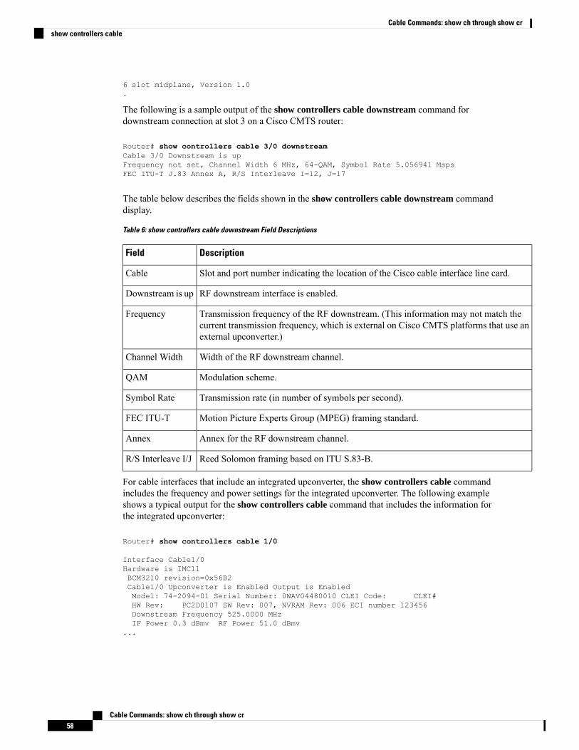
6 slot midplane, Version 1.0.
The following is a sample output of the show controllers cable downstream command fordownstream connection at slot 3 on a Cisco CMTS router:
Router# show controllers cable 3/0 downstreamCable 3/0 Downstream is upFrequency not set, Channel Width 6 MHz, 64-QAM, Symbol Rate 5.056941 MspsFEC ITU-T J.83 Annex A, R/S Interleave I=12, J=17
The table below describes the fields shown in the show controllers cable downstream commanddisplay.
Table 6: show controllers cable downstream Field Descriptions
DescriptionField
Slot and port number indicating the location of the Cisco cable interface line card.Cable
RF downstream interface is enabled.Downstream is up
Transmission frequency of the RF downstream. (This information may not match thecurrent transmission frequency, which is external on Cisco CMTS platforms that use anexternal upconverter.)
Frequency
Width of the RF downstream channel.Channel Width
Modulation scheme.QAM
Transmission rate (in number of symbols per second).Symbol Rate
Motion Picture Experts Group (MPEG) framing standard.FEC ITU-T
Annex for the RF downstream channel.Annex
Reed Solomon framing based on ITU S.83-B.R/S Interleave I/J
For cable interfaces that include an integrated upconverter, the show controllers cable commandincludes the frequency and power settings for the integrated upconverter. The following exampleshows a typical output for the show controllers cable command that includes the information forthe integrated upconverter:
Router# show controllers cable 1/0
Interface Cable1/0Hardware is IMC11BCM3210 revision=0x56B2Cable1/0 Upconverter is Enabled Output is EnabledModel: 74-2094-01 Serial Number: 0WAV04480010 CLEI Code: CLEI#HW Rev: PC2D0107 SW Rev: 007, NVRAM Rev: 006 ECI number 123456Downstream Frequency 525.0000 MHzIF Power 0.3 dBmv RF Power 51.0 dBmv
...
Cable Commands: show ch through show cr58
Cable Commands: show ch through show crshow controllers cable
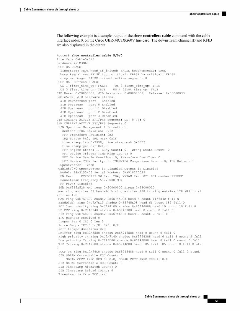
The following example is a sample output of the show controllers cable command with the cableinterface index 0. on the Cisco UBR-MC3XG60V line card. The downstream channel ID and RFIDare also displayed in the output:
Router# show controller cable 5/0/0Interface Cable5/0/0Hardware is M3G60HCCP HA FLAGS:linestate: TRUE hccp_if_inited: FALSE hccphopready: TRUEhccp_keepalive: FALSE hccp_critical: FALSE ha_critical: FALSEdrop_mac_msgs: FALSE current_active_segment: 0
HCCP HA UPStream FLAGS:US 1 first_time_up: FALSE US 2 first_time_up: TRUEUS 3 first_time_up: TRUE US 4 first_time_up: TRUE
JIB Base: 0x20000000, JIB Revision: 0x00000002, Release: 0x00000033Cable5/0/0 JIB hardware status:JIB Downstream port EnabledJIB Upstream port 0 EnabledJIB Upstream port 1 DisabledJIB Upstream port 2 DisabledJIB Upstream port 3 Disabled
JIB CURRENT ACTIVE BPI/PHS Segment: DS: 0 US: 0S/W CURRENT ACTIVE BPI/PHS Segment: 0H/W Spectrum Management Information:Sextant FPGA Revision: 0x1BFFT Transform Revision: 0x2IRQ status 0x0, IRQ mask 0x1Ftime_stamp_lsb 0x739D, time_stamp_msb 0xB8D3time_stamp_gen_csr 0x100FFT Engine State: 1, Busy Count: 0, Wrong State Count: 0FFT Device Trigger Time Miss Count: 0FFT Device Sample Overflow: 0, Transform Overflow: 0FFT Device TSRM Parity: 0, TSRM/TSG Comparison Error: 0, TSG Reload: 1Upconverter: vcomCable5/0/0 Upconverter is Disabled Output is DisabledModel: 74-3153-05 Serial Number: 0WAV10250089HW Rev: PC2D0109 SW Rev: 204, NVRAM Rev: 021 ECI number FFFFFFDownstream Frequency 537.0000 MHzRF Power Disabledidb 0x6565E520 MAC regs 0x20000000 SDRAM 0x28000000mac ring entries 32 bandwidth ring entries 128 tx ring entries 128 MAP tx rientries 128MAC ring 0xC7A7E00 shadow 0x65745D08 head 8 count 1136840 full 0Bandwidth ring 0xC7A7EC0 shadow 0x65745E08 head 61 count 189 full 0PCI low priority ring 0xC7A8100 shadow 0x65746088 head 19 count 19 full 0US CCF ring 0xC7A8340 shadow 0x65746308 head 0 count 0 full 0FIB ring 0xC7A87C0 shadow 0x65746808 head 0 count 0 full 0IPC packets received 0Drops: Par 0 CRC 0 Len 0Force Drops IPC 0 Lo/Hi 0/0, 0/0snfr_fibipc_dmastatus 0x0Sniffer ring 0xC7A8580 shadow 0x65746588 head 0 count 0 full 0High priority Tx ring 0xC7A7140 shadow 0x65744388 head 6 tail 8 count 2 fullLow priority Tx ring 0xC7A6D00 shadow 0x65743B08 head 0 tail 0 count 0 fullTIB Tx ring 0xC7A7580 shadow 0x65744C08 head 105 tail 105 count 0 full 0 stu0PCCF Tx ring 0xC7A79C0 shadow 0x65745488 head 0 tail 0 count 0 full 0 stuckJIB SDRAM Correctable ECC Count: 0
SDRAM_CECC_INFO_REG_0: 0x0, SDRAM_CECC_INFO_REG_1: 0x0JIB SSRAM Correctable ECC Count: 0JIB Timestamp Mismatch Count: 0JIB Timestamp Reload Count: 0Timestamp is from TCC card
Cable Commands: show ch through show cr59
Cable Commands: show ch through show crshow controllers cable
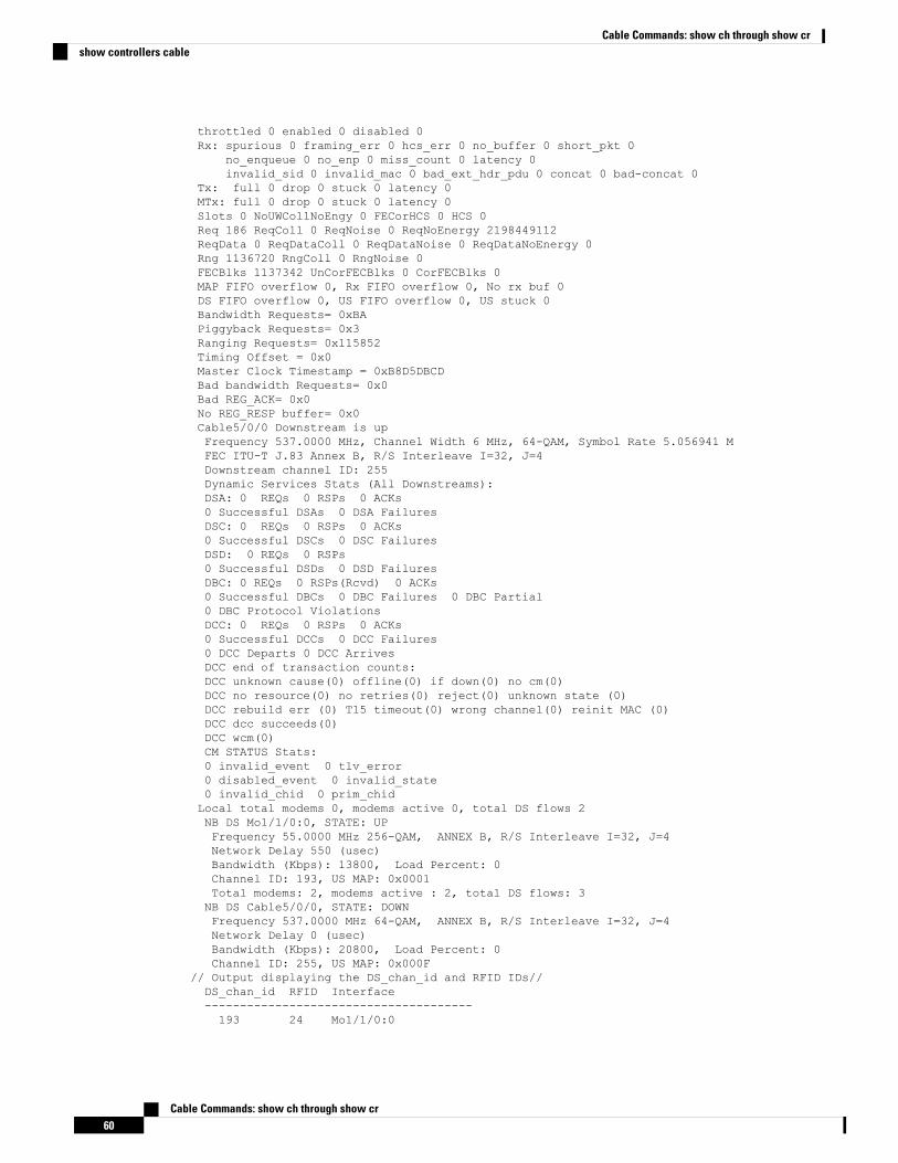
throttled 0 enabled 0 disabled 0Rx: spurious 0 framing_err 0 hcs_err 0 no_buffer 0 short_pkt 0
no_enqueue 0 no_enp 0 miss_count 0 latency 0invalid_sid 0 invalid_mac 0 bad_ext_hdr_pdu 0 concat 0 bad-concat 0
Tx: full 0 drop 0 stuck 0 latency 0MTx: full 0 drop 0 stuck 0 latency 0Slots 0 NoUWCollNoEngy 0 FECorHCS 0 HCS 0Req 186 ReqColl 0 ReqNoise 0 ReqNoEnergy 2198449112ReqData 0 ReqDataColl 0 ReqDataNoise 0 ReqDataNoEnergy 0Rng 1136720 RngColl 0 RngNoise 0FECBlks 1137342 UnCorFECBlks 0 CorFECBlks 0MAP FIFO overflow 0, Rx FIFO overflow 0, No rx buf 0DS FIFO overflow 0, US FIFO overflow 0, US stuck 0Bandwidth Requests= 0xBAPiggyback Requests= 0x3Ranging Requests= 0x115852Timing Offset = 0x0Master Clock Timestamp = 0xB8D5DBCDBad bandwidth Requests= 0x0Bad REG_ACK= 0x0No REG_RESP buffer= 0x0Cable5/0/0 Downstream is upFrequency 537.0000 MHz, Channel Width 6 MHz, 64-QAM, Symbol Rate 5.056941 MFEC ITU-T J.83 Annex B, R/S Interleave I=32, J=4Downstream channel ID: 255Dynamic Services Stats (All Downstreams):DSA: 0 REQs 0 RSPs 0 ACKs0 Successful DSAs 0 DSA FailuresDSC: 0 REQs 0 RSPs 0 ACKs0 Successful DSCs 0 DSC FailuresDSD: 0 REQs 0 RSPs0 Successful DSDs 0 DSD FailuresDBC: 0 REQs 0 RSPs(Rcvd) 0 ACKs0 Successful DBCs 0 DBC Failures 0 DBC Partial0 DBC Protocol ViolationsDCC: 0 REQs 0 RSPs 0 ACKs0 Successful DCCs 0 DCC Failures0 DCC Departs 0 DCC ArrivesDCC end of transaction counts:DCC unknown cause(0) offline(0) if down(0) no cm(0)DCC no resource(0) no retries(0) reject(0) unknown state (0)DCC rebuild err (0) T15 timeout(0) wrong channel(0) reinit MAC (0)DCC dcc succeeds(0)DCC wcm(0)CM STATUS Stats:0 invalid_event 0 tlv_error0 disabled_event 0 invalid_state0 invalid_chid 0 prim_chidLocal total modems 0, modems active 0, total DS flows 2NB DS Mo1/1/0:0, STATE: UPFrequency 55.0000 MHz 256-QAM, ANNEX B, R/S Interleave I=32, J=4Network Delay 550 (usec)Bandwidth (Kbps): 13800, Load Percent: 0Channel ID: 193, US MAP: 0x0001Total modems: 2, modems active : 2, total DS flows: 3NB DS Cable5/0/0, STATE: DOWNFrequency 537.0000 MHz 64-QAM, ANNEX B, R/S Interleave I=32, J=4Network Delay 0 (usec)Bandwidth (Kbps): 20800, Load Percent: 0Channel ID: 255, US MAP: 0x000F
// Output displaying the DS_chan_id and RFID IDs//DS_chan_id RFID Interface--------------------------------------193 24 Mo1/1/0:0
Cable Commands: show ch through show cr60
Cable Commands: show ch through show crshow controllers cable
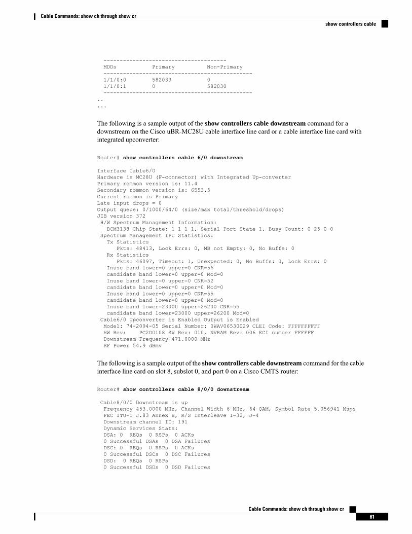
--------------------------------------MDDs Primary Non-Primary----------------------------------------------1/1/0:0 582033 01/1/0:1 0 582030----------------------------------------------
..
...
The following is a sample output of the show controllers cable downstream command for adownstream on the Cisco uBR-MC28U cable interface line card or a cable interface line card withintegrated upconverter:
Router# show controllers cable 6/0 downstream
Interface Cable6/0Hardware is MC28U (F-connector) with Integrated Up-converterPrimary rommon version is: 11.4Secondary rommon version is: 6553.5Current rommon is PrimaryLate input drops = 0Output queue: 0/1000/64/0 (size/max total/threshold/drops)JIB version 372H/W Spectrum Management Information:BCM3138 Chip State: 1 1 1 1, Serial Port State 1, Busy Count: 0 25 0 0
Spectrum Management IPC Statistics:Tx Statistics
Pkts: 48413, Lock Errs: 0, MB not Empty: 0, No Buffs: 0Rx Statistics
Pkts: 46097, Timeout: 1, Unexpected: 0, No Buffs: 0, Lock Errs: 0Inuse band lower=0 upper=0 CNR=56candidate band lower=0 upper=0 Mod=0Inuse band lower=0 upper=0 CNR=52candidate band lower=0 upper=0 Mod=0Inuse band lower=0 upper=0 CNR=55candidate band lower=0 upper=0 Mod=0Inuse band lower=23000 upper=26200 CNR=55candidate band lower=23000 upper=26200 Mod=0
Cable6/0 Upconverter is Enabled Output is EnabledModel: 74-2094-05 Serial Number: 0WAV06530029 CLEI Code: FFFFFFFFFFHW Rev: PC2D0108 SW Rev: 010, NVRAM Rev: 006 ECI number FFFFFFDownstream Frequency 471.0000 MHzRF Power 54.9 dBmv
The following is a sample output of the show controllers cable downstream command for the cableinterface line card on slot 8, subslot 0, and port 0 on a Cisco CMTS router:
Router# show controllers cable 8/0/0 downstream
Cable8/0/0 Downstream is upFrequency 453.0000 MHz, Channel Width 6 MHz, 64-QAM, Symbol Rate 5.056941 MspsFEC ITU-T J.83 Annex B, R/S Interleave I=32, J=4Downstream channel ID: 191Dynamic Services Stats:DSA: 0 REQs 0 RSPs 0 ACKs0 Successful DSAs 0 DSA FailuresDSC: 0 REQs 0 RSPs 0 ACKs0 Successful DSCs 0 DSC FailuresDSD: 0 REQs 0 RSPs0 Successful DSDs 0 DSD Failures
Cable Commands: show ch through show cr61
Cable Commands: show ch through show crshow controllers cable
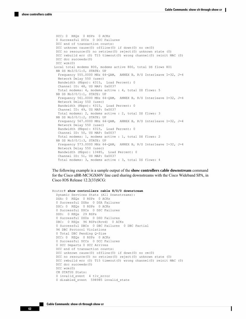
DCC: 0 REQs 0 RSPs 0 ACKs0 Successful DCCs 0 DCC FailuresDCC end of transaction counts:DCC unknown cause(0) offline(0) if down(0) no cm(0)DCC no resource(0) no retries(0) reject(0) unknown state (0)DCC rebuild err (0) T15 timeout(0) wrong channel(0) reinit MAC (0)DCC dcc succeeds(0)DCC wcm(0)Local total modems 800, modems active 800, total DS flows 801NB DS Mo3/0/1:0, STATE: UPFrequency 555.0000 MHz 64-QAM, ANNEX B, R/S Interleave I=32, J=4Network Delay 550 (usec)Bandwidth (Kbps): 4315, Load Percent: 0Channel ID: 48, US MAP: 0x0037Total modems: 4, modems active : 4, total DS flows: 5NB DS Mo3/0/1:1, STATE: UPFrequency 561.0000 MHz 64-QAM, ANNEX B, R/S Interleave I=32, J=4Network Delay 550 (usec)Bandwidth (Kbps): 4315, Load Percent: 0Channel ID: 49, US MAP: 0x0037Total modems: 2, modems active : 2, total DS flows: 3NB DS Mo3/0/1:2, STATE: UPFrequency 567.0000 MHz 64-QAM, ANNEX B, R/S Interleave I=32, J=4Network Delay 550 (usec)Bandwidth (Kbps): 4315, Load Percent: 0Channel ID: 50, US MAP: 0x0037Total modems: 1, modems active : 1, total DS flows: 2NB DS Mo3/0/1:3, STATE: UPFrequency 573.0000 MHz 64-QAM, ANNEX B, R/S Interleave I=32, J=4Network Delay 550 (usec)Bandwidth (Kbps): 13485, Load Percent: 0Channel ID: 51, US MAP: 0x0037Total modems: 3, modems active : 3, total DS flows: 4
The following example is a sample output of the show controllers cable downstream commandfor the Cisco uBR-MC3GX60V line card sharing downstreams with the Cisco Wideband SPA, inCisco IOS Release 12.2(33)SCG:
Router# show controllers cable 8/0/0 downstreamDynamic Services Stats (All Downstreams):DSA: 0 REQs 0 RSPs 0 ACKs0 Successful DSAs 0 DSA FailuresDSC: 0 REQs 0 RSPs 0 ACKs0 Successful DSCs 0 DSC FailuresDSD: 0 REQs 29 RSPs0 Successful DSDs 0 DSD FailuresDBC: 0 REQs 96 RSPs(Rcvd) 0 ACKs0 Successful DBCs 0 DBC Failures 0 DBC Partial96 DBC Protocol Violations0 Total DBC Pending Q-SizeDCC: 0 REQs 0 RSPs 0 ACKs0 Successful DCCs 0 DCC Failures0 DCC Departs 0 DCC ArrivesDCC end of transaction counts:DCC unknown cause(0) offline(0) if down(0) no cm(0)DCC no resource(0) no retries(0) reject(0) unknown state (0)DCC rebuild err (0) T15 timeout(0) wrong channel(0) reinit MAC (0)DCC dcc succeeds(0)DCC wcm(0)CM STATUS Stats:0 invalid_event 4 tlv_error0 disabled_event 598985 invalid_state
Cable Commands: show ch through show cr62
Cable Commands: show ch through show crshow controllers cable
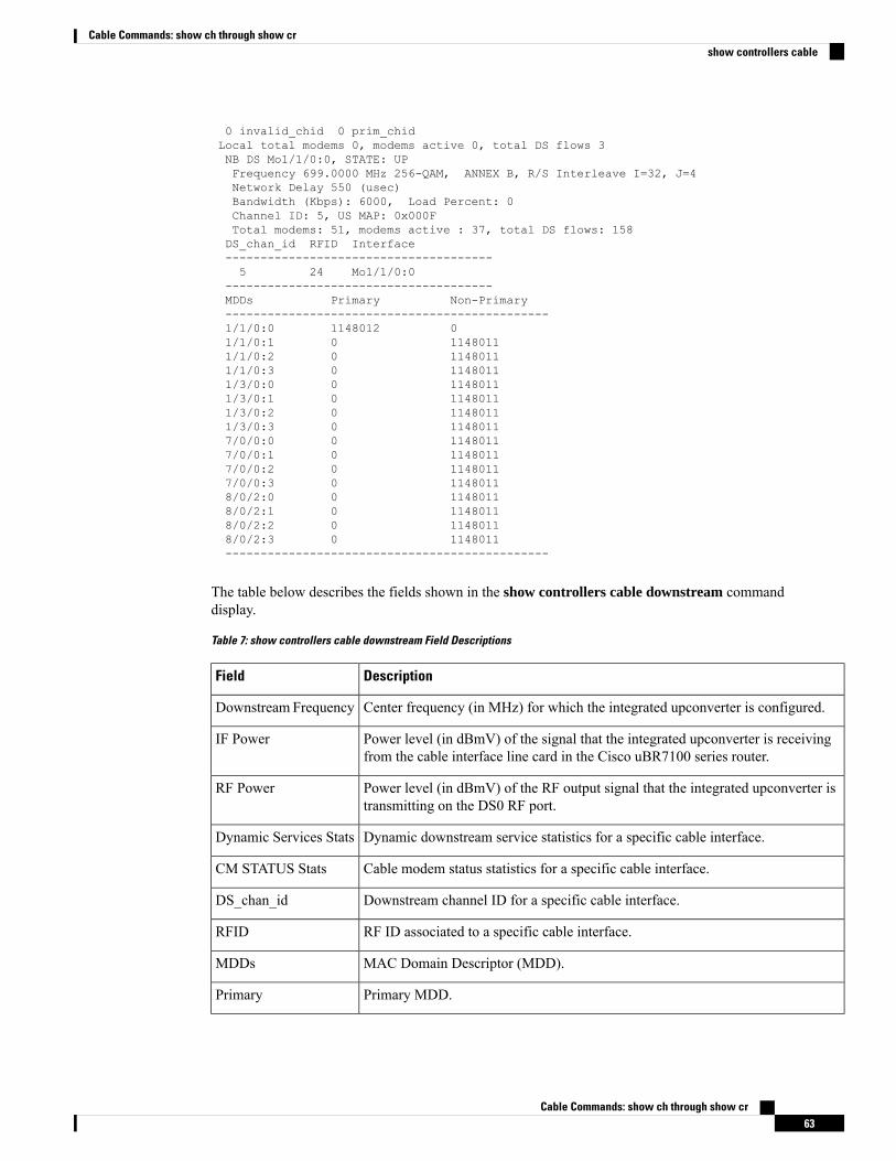
0 invalid_chid 0 prim_chidLocal total modems 0, modems active 0, total DS flows 3NB DS Mo1/1/0:0, STATE: UPFrequency 699.0000 MHz 256-QAM, ANNEX B, R/S Interleave I=32, J=4Network Delay 550 (usec)Bandwidth (Kbps): 6000, Load Percent: 0Channel ID: 5, US MAP: 0x000FTotal modems: 51, modems active : 37, total DS flows: 158DS_chan_id RFID Interface--------------------------------------5 24 Mo1/1/0:0
--------------------------------------MDDs Primary Non-Primary----------------------------------------------1/1/0:0 1148012 01/1/0:1 0 11480111/1/0:2 0 11480111/1/0:3 0 11480111/3/0:0 0 11480111/3/0:1 0 11480111/3/0:2 0 11480111/3/0:3 0 11480117/0/0:0 0 11480117/0/0:1 0 11480117/0/0:2 0 11480117/0/0:3 0 11480118/0/2:0 0 11480118/0/2:1 0 11480118/0/2:2 0 11480118/0/2:3 0 1148011----------------------------------------------
The table below describes the fields shown in the show controllers cable downstream commanddisplay.
Table 7: show controllers cable downstream Field Descriptions
DescriptionField
Center frequency (in MHz) for which the integrated upconverter is configured.Downstream Frequency
Power level (in dBmV) of the signal that the integrated upconverter is receivingfrom the cable interface line card in the Cisco uBR7100 series router.
IF Power
Power level (in dBmV) of the RF output signal that the integrated upconverter istransmitting on the DS0 RF port.
RF Power
Dynamic downstream service statistics for a specific cable interface.Dynamic Services Stats
Cable modem status statistics for a specific cable interface.CM STATUS Stats
Downstream channel ID for a specific cable interface.DS_chan_id
RF ID associated to a specific cable interface.RFID
MAC Domain Descriptor (MDD).MDDs
Primary MDD.Primary
Cable Commands: show ch through show cr63
Cable Commands: show ch through show crshow controllers cable
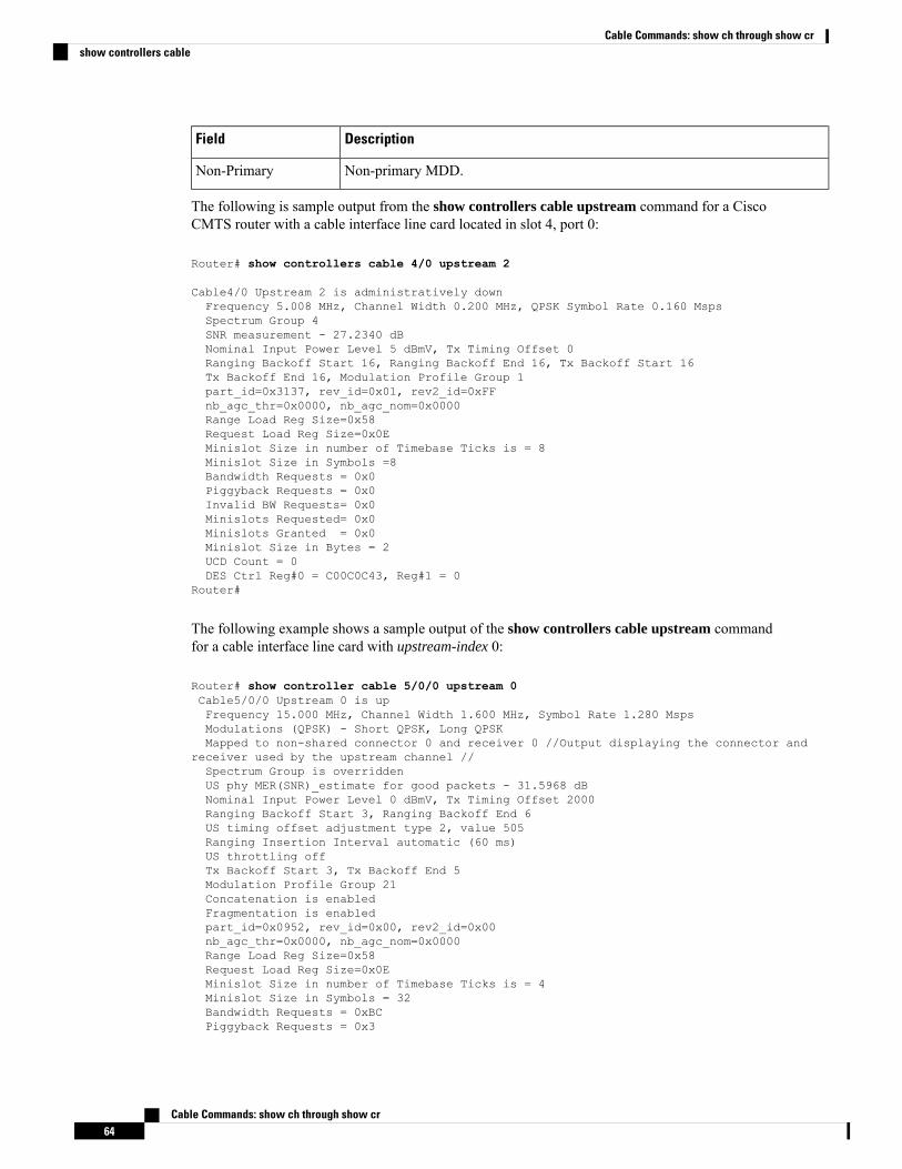
DescriptionField
Non-primary MDD.Non-Primary
The following is sample output from the show controllers cable upstream command for a CiscoCMTS router with a cable interface line card located in slot 4, port 0:
Router# show controllers cable 4/0 upstream 2
Cable4/0 Upstream 2 is administratively downFrequency 5.008 MHz, Channel Width 0.200 MHz, QPSK Symbol Rate 0.160 MspsSpectrum Group 4SNR measurement - 27.2340 dBNominal Input Power Level 5 dBmV, Tx Timing Offset 0Ranging Backoff Start 16, Ranging Backoff End 16, Tx Backoff Start 16Tx Backoff End 16, Modulation Profile Group 1part_id=0x3137, rev_id=0x01, rev2_id=0xFFnb_agc_thr=0x0000, nb_agc_nom=0x0000Range Load Reg Size=0x58Request Load Reg Size=0x0EMinislot Size in number of Timebase Ticks is = 8Minislot Size in Symbols =8Bandwidth Requests = 0x0Piggyback Requests = 0x0Invalid BW Requests= 0x0Minislots Requested= 0x0Minislots Granted = 0x0Minislot Size in Bytes = 2UCD Count = 0DES Ctrl Reg#0 = C00C0C43, Reg#1 = 0
Router#
The following example shows a sample output of the show controllers cable upstream commandfor a cable interface line card with upstream-index 0:
Router# show controller cable 5/0/0 upstream 0Cable5/0/0 Upstream 0 is upFrequency 15.000 MHz, Channel Width 1.600 MHz, Symbol Rate 1.280 MspsModulations (QPSK) - Short QPSK, Long QPSKMapped to non-shared connector 0 and receiver 0 //Output displaying the connector and
receiver used by the upstream channel //Spectrum Group is overriddenUS phy MER(SNR)_estimate for good packets - 31.5968 dBNominal Input Power Level 0 dBmV, Tx Timing Offset 2000Ranging Backoff Start 3, Ranging Backoff End 6US timing offset adjustment type 2, value 505Ranging Insertion Interval automatic (60 ms)US throttling offTx Backoff Start 3, Tx Backoff End 5Modulation Profile Group 21Concatenation is enabledFragmentation is enabledpart_id=0x0952, rev_id=0x00, rev2_id=0x00nb_agc_thr=0x0000, nb_agc_nom=0x0000Range Load Reg Size=0x58Request Load Reg Size=0x0EMinislot Size in number of Timebase Ticks is = 4Minislot Size in Symbols = 32Bandwidth Requests = 0xBCPiggyback Requests = 0x3
Cable Commands: show ch through show cr64
Cable Commands: show ch through show crshow controllers cable
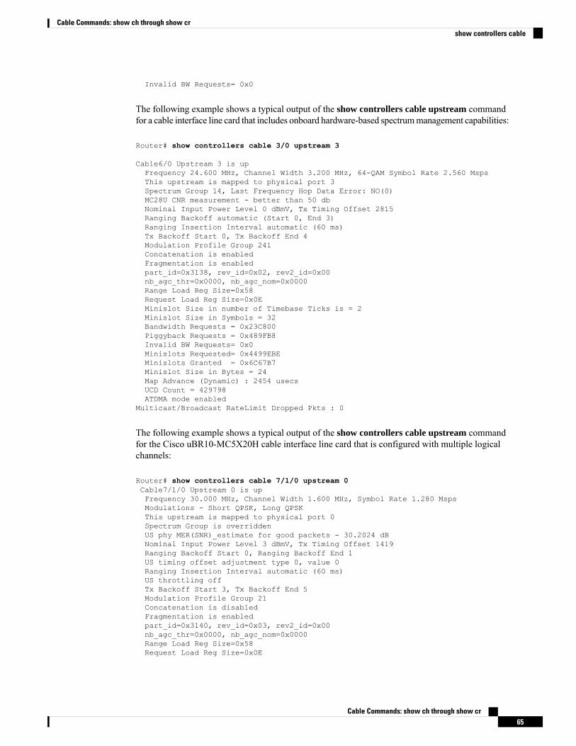
Invalid BW Requests= 0x0
The following example shows a typical output of the show controllers cable upstream commandfor a cable interface line card that includes onboard hardware-based spectrummanagement capabilities:
Router# show controllers cable 3/0 upstream 3
Cable6/0 Upstream 3 is upFrequency 24.600 MHz, Channel Width 3.200 MHz, 64-QAM Symbol Rate 2.560 MspsThis upstream is mapped to physical port 3Spectrum Group 14, Last Frequency Hop Data Error: NO(0)MC28U CNR measurement - better than 50 dbNominal Input Power Level 0 dBmV, Tx Timing Offset 2815Ranging Backoff automatic (Start 0, End 3)Ranging Insertion Interval automatic (60 ms)Tx Backoff Start 0, Tx Backoff End 4Modulation Profile Group 241Concatenation is enabledFragmentation is enabledpart_id=0x3138, rev_id=0x02, rev2_id=0x00nb_agc_thr=0x0000, nb_agc_nom=0x0000Range Load Reg Size=0x58Request Load Reg Size=0x0EMinislot Size in number of Timebase Ticks is = 2Minislot Size in Symbols = 32Bandwidth Requests = 0x23C800Piggyback Requests = 0x489FB8Invalid BW Requests= 0x0Minislots Requested= 0x4499EBEMinislots Granted = 0x6C67B7Minislot Size in Bytes = 24Map Advance (Dynamic) : 2454 usecsUCD Count = 429798ATDMA mode enabled
Multicast/Broadcast RateLimit Dropped Pkts : 0
The following example shows a typical output of the show controllers cable upstream commandfor the Cisco uBR10-MC5X20H cable interface line card that is configured with multiple logicalchannels:
Router# show controllers cable 7/1/0 upstream 0Cable7/1/0 Upstream 0 is upFrequency 30.000 MHz, Channel Width 1.600 MHz, Symbol Rate 1.280 MspsModulations - Short QPSK, Long QPSKThis upstream is mapped to physical port 0Spectrum Group is overriddenUS phy MER(SNR)_estimate for good packets - 30.2024 dBNominal Input Power Level 3 dBmV, Tx Timing Offset 1419Ranging Backoff Start 0, Ranging Backoff End 1US timing offset adjustment type 0, value 0Ranging Insertion Interval automatic (60 ms)US throttling offTx Backoff Start 3, Tx Backoff End 5Modulation Profile Group 21Concatenation is disabledFragmentation is enabledpart_id=0x3140, rev_id=0x03, rev2_id=0x00nb_agc_thr=0x0000, nb_agc_nom=0x0000Range Load Reg Size=0x58Request Load Reg Size=0x0E
Cable Commands: show ch through show cr65
Cable Commands: show ch through show crshow controllers cable
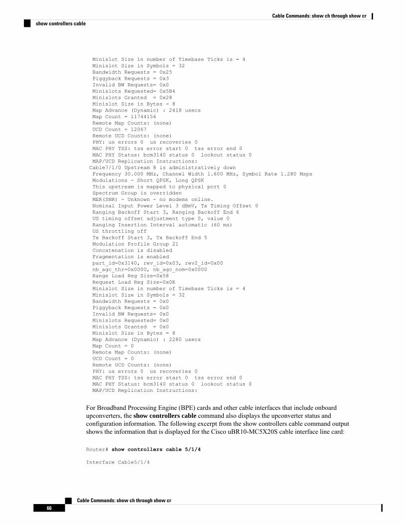
Minislot Size in number of Timebase Ticks is = 4Minislot Size in Symbols = 32Bandwidth Requests = 0x25Piggyback Requests = 0x3Invalid BW Requests= 0x0Minislots Requested= 0x5B4Minislots Granted = 0x28Minislot Size in Bytes = 8Map Advance (Dynamic) : 2418 usecsMap Count = 11744156Remote Map Counts: (none)UCD Count = 12067Remote UCD Counts: (none)PHY: us errors 0 us recoveries 0MAC PHY TSS: tss error start 0 tss error end 0MAC PHY Status: bcm3140 status 0 lookout status 0MAP/UCD Replication Instructions:Cable7/1/0 Upstream 8 is administratively downFrequency 30.000 MHz, Channel Width 1.600 MHz, Symbol Rate 1.280 MspsModulations - Short QPSK, Long QPSKThis upstream is mapped to physical port 0Spectrum Group is overriddenMER(SNR) - Unknown - no modems online.Nominal Input Power Level 3 dBmV, Tx Timing Offset 0Ranging Backoff Start 3, Ranging Backoff End 6US timing offset adjustment type 0, value 0Ranging Insertion Interval automatic (60 ms)US throttling offTx Backoff Start 3, Tx Backoff End 5Modulation Profile Group 21Concatenation is disabledFragmentation is enabledpart_id=0x3140, rev_id=0x03, rev2_id=0x00nb_agc_thr=0x0000, nb_agc_nom=0x0000Range Load Reg Size=0x58Request Load Reg Size=0x0EMinislot Size in number of Timebase Ticks is = 4Minislot Size in Symbols = 32Bandwidth Requests = 0x0Piggyback Requests = 0x0Invalid BW Requests= 0x0Minislots Requested= 0x0Minislots Granted = 0x0Minislot Size in Bytes = 8Map Advance (Dynamic) : 2280 usecsMap Count = 0Remote Map Counts: (none)UCD Count = 0Remote UCD Counts: (none)PHY: us errors 0 us recoveries 0MAC PHY TSS: tss error start 0 tss error end 0MAC PHY Status: bcm3140 status 0 lookout status 0MAP/UCD Replication Instructions:
For Broadband Processing Engine (BPE) cards and other cable interfaces that include onboardupconverters, the show controllers cable command also displays the upconverter status andconfiguration information. The following excerpt from the show controllers cable command outputshows the information that is displayed for the Cisco uBR10-MC5X20S cable interface line card:
Router# show controllers cable 5/1/4
Interface Cable5/1/4
Cable Commands: show ch through show cr66
Cable Commands: show ch through show crshow controllers cable
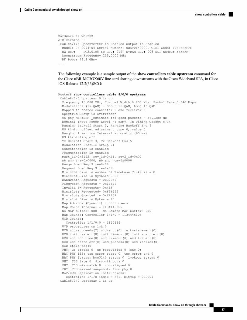
Hardware is MC520SJIB version 66Cable5/1/4 Upconverter is Enabled Output is EnabledModel: 74-2094-04 Serial Number: 0WAV0649000L CLEI Code: FFFFFFFFFFHW Rev: PC2D0108 SW Rev: 010, NVRAM Rev: 006 ECI number FFFFFFDownstream Frequency 255.0000 MHzRF Power 49.8 dBmv
...
The following example is a sample output of the show controllers cable upstream command forthe Cisco uBR-MC3GX60V line card sharing downstreams with the Cisco Wideband SPA, in CiscoIOS Release 12.2(33)SCG:
Router# show controllers cable 8/0/0 upstreamCable8/0/0 Upstream 0 is upFrequency 15.000 MHz, Channel Width 0.800 MHz, Symbol Rate 0.640 MspsModulations (16-QAM) - Short 16-QAM, Long 16-QAMMapped to shared connector 0 and receiver 0Spectrum Group is overriddenUS phy MER(SNR)_estimate for good packets - 36.1280 dBNominal Input Power Level -4 dBmV, Tx Timing Offset 5734Ranging Backoff Start 3, Ranging Backoff End 6US timing offset adjustment type 0, value 0Ranging Insertion Interval automatic (60 ms)US throttling offTx Backoff Start 3, Tx Backoff End 5Modulation Profile Group 21Concatenation is enabledFragmentation is enabledpart_id=0x3142, rev_id=0xB1, rev2_id=0x00nb_agc_thr=0x0000, nb_agc_nom=0x0000Range Load Reg Size=0x58Request Load Reg Size=0x0EMinislot Size in number of Timebase Ticks is = 8Minislot Size in Symbols = 32Bandwidth Requests = 0xC7957Piggyback Requests = 0x19899Invalid BW Requests= 0x4BFMinislots Requested= 0xF2E365Minislots Granted = 0xE240AMinislot Size in Bytes = 16Map Advance (Dynamic) : 3389 usecsMap Count Internal = 1134448325No MAP buffer= 0x0 No Remote MAP buffer= 0x0Map Counts: Controller 1/1/0 = 1134446105UCD Counts:Controller 1/1/0:0 = 1150386
UCD procedures on lch 0UCD ucd-succeeds(2) ucd-shut(0) init-state-err(0)UCD init-tss-err(0) init-timeout(0) init-start-err(0)UCD ucd-ccc-time(0) ucd-timeout(0) ucd-tss-err(0)UCD ucd-state-err(0) ucd-process(0) ucd-retries(0)UCD stale-tss(0)PHY: us errors 0 us recoveries 0 (enp 0)MAC PHY TSS: tss error start 0 tss error end 0MAC PHY Status: bcm3140 status 0 lookout status 0PHY: TSS late 0 discontinuous 0PHY: TSS mis-match 0 not-aligned 0PHY: TSS missed snapshots from phy 0MAP/UCD Replication Instructions:Controller 1/1/0 index = 361, bitmap = 0x0001
Cable8/0/0 Upstream 1 is up
Cable Commands: show ch through show cr67
Cable Commands: show ch through show crshow controllers cable
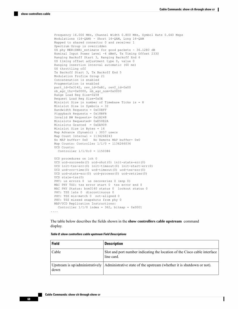
Frequency 16.000 MHz, Channel Width 0.800 MHz, Symbol Rate 0.640 MspsModulations (16-QAM) - Short 16-QAM, Long 16-QAMMapped to shared connector 0 and receiver 1Spectrum Group is overriddenUS phy MER(SNR)_estimate for good packets - 36.1280 dBNominal Input Power Level -4 dBmV, Tx Timing Offset 2330Ranging Backoff Start 3, Ranging Backoff End 6US timing offset adjustment type 0, value 0Ranging Insertion Interval automatic (60 ms)US throttling offTx Backoff Start 3, Tx Backoff End 5Modulation Profile Group 21Concatenation is enabledFragmentation is enabledpart_id=0x3142, rev_id=0xB1, rev2_id=0x00nb_agc_thr=0x0000, nb_agc_nom=0x0000Range Load Reg Size=0x58Request Load Reg Size=0x0EMinislot Size in number of Timebase Ticks is = 8Minislot Size in Symbols = 32Bandwidth Requests = 0xC0BFFPiggyback Requests = 0x18BFBInvalid BW Requests= 0x1B248Minislots Requested= 0xE50E2AMinislots Granted = 0xDA909Minislot Size in Bytes = 16Map Advance (Dynamic) : 3057 usecsMap Count Internal = 1134268243No MAP buffer= 0x0 No Remote MAP buffer= 0x0Map Counts: Controller 1/1/0 = 1134266034UCD Counts:Controller 1/1/0:0 = 1150386
UCD procedures on lch 0UCD ucd-succeeds(2) ucd-shut(0) init-state-err(0)UCD init-tss-err(0) init-timeout(0) init-start-err(0)UCD ucd-ccc-time(0) ucd-timeout(0) ucd-tss-err(0)UCD ucd-state-err(0) ucd-process(0) ucd-retries(0)UCD stale-tss(0)PHY: us errors 0 us recoveries 0 (enp 0)MAC PHY TSS: tss error start 0 tss error end 0MAC PHY Status: bcm3140 status 0 lookout status 0PHY: TSS late 0 discontinuous 0PHY: TSS mis-match 0 not-aligned 0PHY: TSS missed snapshots from phy 0MAP/UCD Replication Instructions:Controller 1/1/0 index = 362, bitmap = 0x0001
....
The table below describes the fields shown in the show controllers cable upstream commanddisplay.
Table 8: show controllers cable upstream Field Descriptions
DescriptionField
Slot and port number indicating the location of the Cisco cable interfaceline card.
Cable
Administrative state of the upstream (whether it is shutdown or not).Upstream is up/administrativelydown
Cable Commands: show ch through show cr68
Cable Commands: show ch through show crshow controllers cable
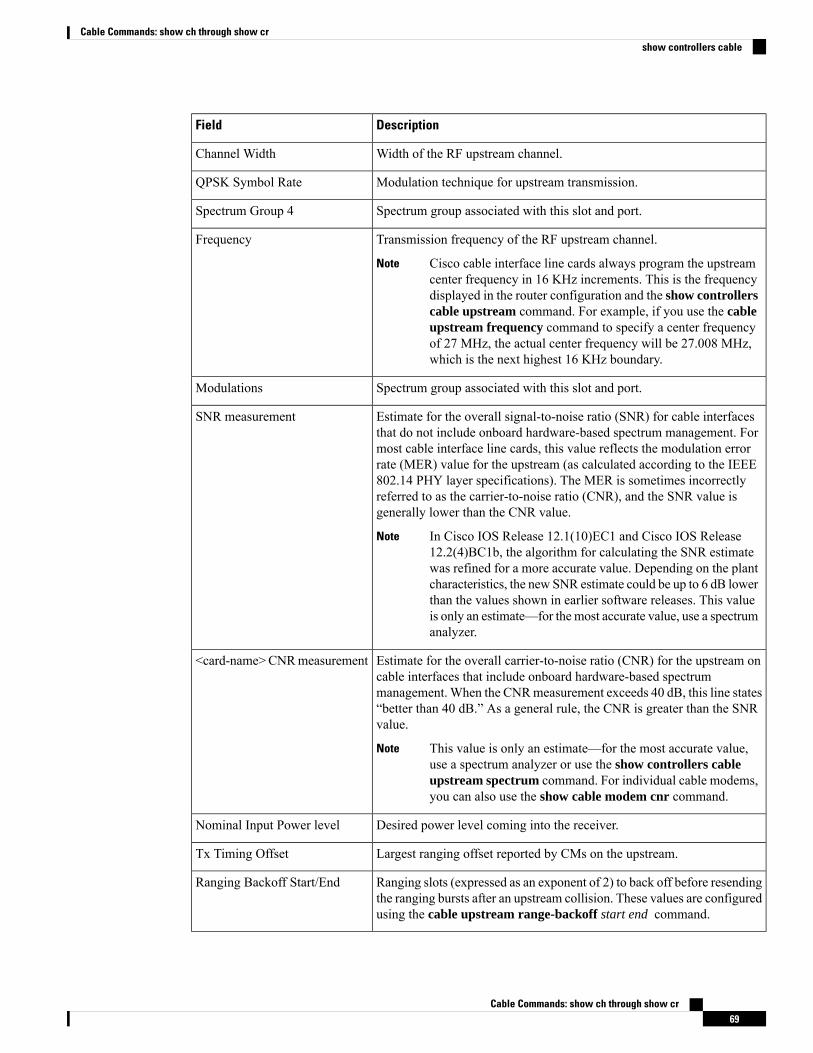
DescriptionField
Width of the RF upstream channel.Channel Width
Modulation technique for upstream transmission.QPSK Symbol Rate
Spectrum group associated with this slot and port.Spectrum Group 4
Transmission frequency of the RF upstream channel.
Cisco cable interface line cards always program the upstreamcenter frequency in 16 KHz increments. This is the frequencydisplayed in the router configuration and the show controllerscable upstream command. For example, if you use the cableupstream frequency command to specify a center frequencyof 27 MHz, the actual center frequency will be 27.008 MHz,which is the next highest 16 KHz boundary.
Note
Frequency
Spectrum group associated with this slot and port.Modulations
Estimate for the overall signal-to-noise ratio (SNR) for cable interfacesthat do not include onboard hardware-based spectrum management. Formost cable interface line cards, this value reflects the modulation errorrate (MER) value for the upstream (as calculated according to the IEEE802.14 PHY layer specifications). The MER is sometimes incorrectlyreferred to as the carrier-to-noise ratio (CNR), and the SNR value isgenerally lower than the CNR value.
In Cisco IOS Release 12.1(10)EC1 and Cisco IOS Release12.2(4)BC1b, the algorithm for calculating the SNR estimatewas refined for a more accurate value. Depending on the plantcharacteristics, the new SNR estimate could be up to 6 dB lowerthan the values shown in earlier software releases. This valueis only an estimate—for the most accurate value, use a spectrumanalyzer.
Note
SNR measurement
Estimate for the overall carrier-to-noise ratio (CNR) for the upstream oncable interfaces that include onboard hardware-based spectrummanagement.When the CNRmeasurement exceeds 40 dB, this line states“better than 40 dB.” As a general rule, the CNR is greater than the SNRvalue.
This value is only an estimate—for the most accurate value,use a spectrum analyzer or use the show controllers cableupstream spectrum command. For individual cable modems,you can also use the show cable modem cnr command.
Note
<card-name>CNRmeasurement
Desired power level coming into the receiver.Nominal Input Power level
Largest ranging offset reported by CMs on the upstream.Tx Timing Offset
Ranging slots (expressed as an exponent of 2) to back off before resendingthe ranging bursts after an upstream collision. These values are configuredusing the cable upstream range-backoff start end command.
Ranging Backoff Start/End
Cable Commands: show ch through show cr69
Cable Commands: show ch through show crshow controllers cable
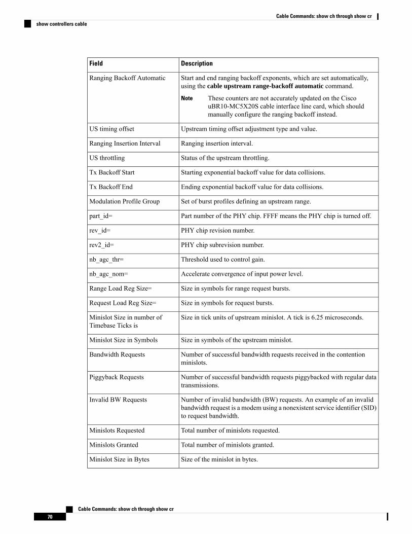
DescriptionField
Start and end ranging backoff exponents, which are set automatically,using the cable upstream range-backoff automatic command.
These counters are not accurately updated on the CiscouBR10-MC5X20S cable interface line card, which shouldmanually configure the ranging backoff instead.
Note
Ranging Backoff Automatic
Upstream timing offset adjustment type and value.US timing offset
Ranging insertion interval.Ranging Insertion Interval
Status of the upstream throttling.US throttling
Starting exponential backoff value for data collisions.Tx Backoff Start
Ending exponential backoff value for data collisions.Tx Backoff End
Set of burst profiles defining an upstream range.Modulation Profile Group
Part number of the PHY chip. FFFF means the PHY chip is turned off.part_id=
PHY chip revision number.rev_id=
PHY chip subrevision number.rev2_id=
Threshold used to control gain.nb_agc_thr=
Accelerate convergence of input power level.nb_agc_nom=
Size in symbols for range request bursts.Range Load Reg Size=
Size in symbols for request bursts.Request Load Reg Size=
Size in tick units of upstream minislot. A tick is 6.25 microseconds.Minislot Size in number ofTimebase Ticks is
Size in symbols of the upstream minislot.Minislot Size in Symbols
Number of successful bandwidth requests received in the contentionminislots.
Bandwidth Requests
Number of successful bandwidth requests piggybacked with regular datatransmissions.
Piggyback Requests
Number of invalid bandwidth (BW) requests. An example of an invalidbandwidth request is a modem using a nonexistent service identifier (SID)to request bandwidth.
Invalid BW Requests
Total number of minislots requested.Minislots Requested
Total number of minislots granted.Minislots Granted
Size of the minislot in bytes.Minislot Size in Bytes
Cable Commands: show ch through show cr70
Cable Commands: show ch through show crshow controllers cable
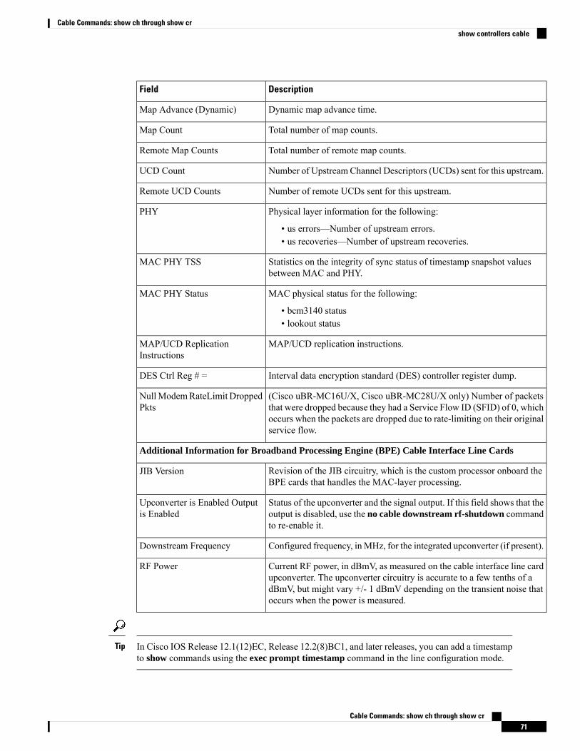
DescriptionField
Dynamic map advance time.Map Advance (Dynamic)
Total number of map counts.Map Count
Total number of remote map counts.Remote Map Counts
Number of Upstream Channel Descriptors (UCDs) sent for this upstream.UCD Count
Number of remote UCDs sent for this upstream.Remote UCD Counts
Physical layer information for the following:
• us errors—Number of upstream errors.• us recoveries—Number of upstream recoveries.
PHY
Statistics on the integrity of sync status of timestamp snapshot valuesbetween MAC and PHY.
MAC PHY TSS
MAC physical status for the following:
• bcm3140 status• lookout status
MAC PHY Status
MAP/UCD replication instructions.MAP/UCD ReplicationInstructions
Interval data encryption standard (DES) controller register dump.DES Ctrl Reg # =
(Cisco uBR-MC16U/X, Cisco uBR-MC28U/X only) Number of packetsthat were dropped because they had a Service Flow ID (SFID) of 0, whichoccurs when the packets are dropped due to rate-limiting on their originalservice flow.
NullModemRateLimit DroppedPkts
Additional Information for Broadband Processing Engine (BPE) Cable Interface Line Cards
Revision of the JIB circuitry, which is the custom processor onboard theBPE cards that handles the MAC-layer processing.
JIB Version
Status of the upconverter and the signal output. If this field shows that theoutput is disabled, use the no cable downstream rf-shutdown commandto re-enable it.
Upconverter is Enabled Outputis Enabled
Configured frequency, inMHz, for the integrated upconverter (if present).Downstream Frequency
Current RF power, in dBmV, as measured on the cable interface line cardupconverter. The upconverter circuitry is accurate to a few tenths of adBmV, but might vary +/- 1 dBmV depending on the transient noise thatoccurs when the power is measured.
RF Power
In Cisco IOS Release 12.1(12)EC, Release 12.2(8)BC1, and later releases, you can add a timestampto show commands using the exec prompt timestamp command in the line configuration mode.
Tip
Cable Commands: show ch through show cr71
Cable Commands: show ch through show crshow controllers cable
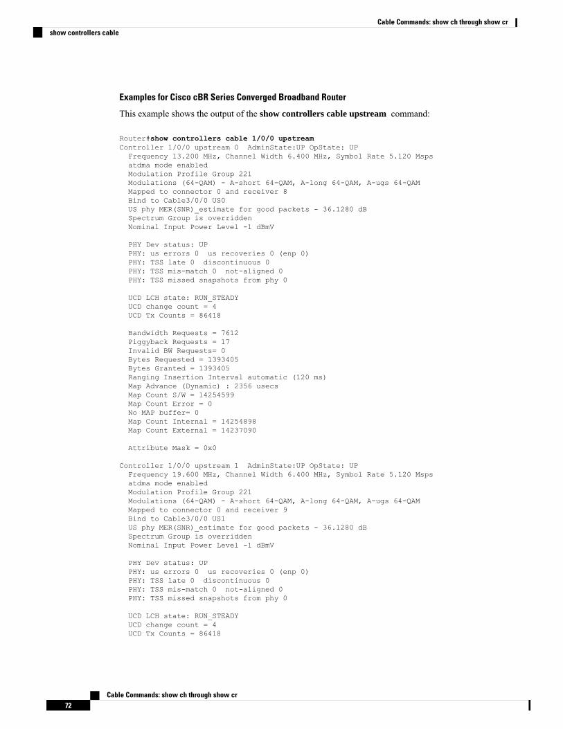
Examples for Cisco cBR Series Converged Broadband Router
This example shows the output of the show controllers cable upstream command:
Router#show controllers cable 1/0/0 upstreamController 1/0/0 upstream 0 AdminState:UP OpState: UPFrequency 13.200 MHz, Channel Width 6.400 MHz, Symbol Rate 5.120 Mspsatdma mode enabledModulation Profile Group 221Modulations (64-QAM) - A-short 64-QAM, A-long 64-QAM, A-ugs 64-QAMMapped to connector 0 and receiver 8Bind to Cable3/0/0 US0US phy MER(SNR)_estimate for good packets - 36.1280 dBSpectrum Group is overriddenNominal Input Power Level -1 dBmV
PHY Dev status: UPPHY: us errors 0 us recoveries 0 (enp 0)PHY: TSS late 0 discontinuous 0PHY: TSS mis-match 0 not-aligned 0PHY: TSS missed snapshots from phy 0
UCD LCH state: RUN_STEADYUCD change count = 4UCD Tx Counts = 86418
Bandwidth Requests = 7612Piggyback Requests = 17Invalid BW Requests= 0Bytes Requested = 1393405Bytes Granted = 1393405Ranging Insertion Interval automatic (120 ms)Map Advance (Dynamic) : 2356 usecsMap Count S/W = 14254599Map Count Error = 0No MAP buffer= 0Map Count Internal = 14254898Map Count External = 14237090
Attribute Mask = 0x0
Controller 1/0/0 upstream 1 AdminState:UP OpState: UPFrequency 19.600 MHz, Channel Width 6.400 MHz, Symbol Rate 5.120 Mspsatdma mode enabledModulation Profile Group 221Modulations (64-QAM) - A-short 64-QAM, A-long 64-QAM, A-ugs 64-QAMMapped to connector 0 and receiver 9Bind to Cable3/0/0 US1US phy MER(SNR)_estimate for good packets - 36.1280 dBSpectrum Group is overriddenNominal Input Power Level -1 dBmV
PHY Dev status: UPPHY: us errors 0 us recoveries 0 (enp 0)PHY: TSS late 0 discontinuous 0PHY: TSS mis-match 0 not-aligned 0PHY: TSS missed snapshots from phy 0
UCD LCH state: RUN_STEADYUCD change count = 4UCD Tx Counts = 86418
Cable Commands: show ch through show cr72
Cable Commands: show ch through show crshow controllers cable
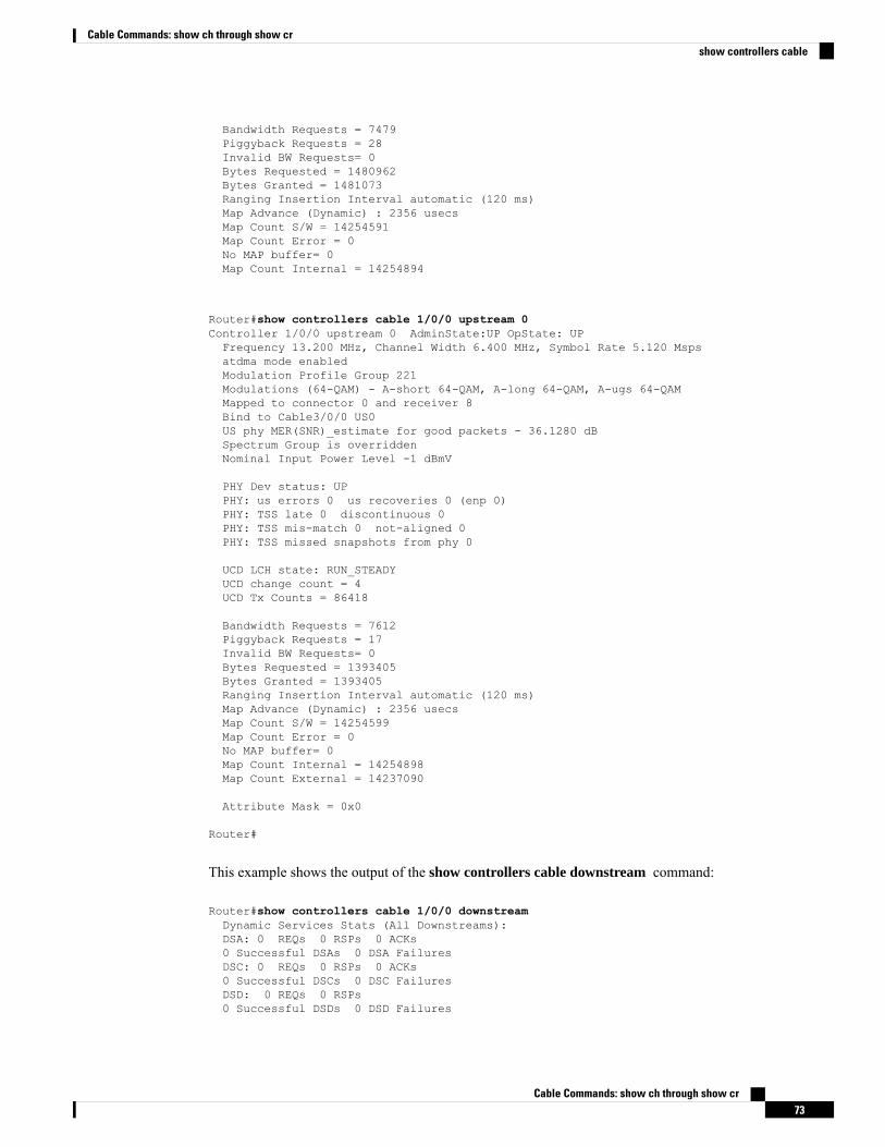
Bandwidth Requests = 7479Piggyback Requests = 28Invalid BW Requests= 0Bytes Requested = 1480962Bytes Granted = 1481073Ranging Insertion Interval automatic (120 ms)Map Advance (Dynamic) : 2356 usecsMap Count S/W = 14254591Map Count Error = 0No MAP buffer= 0Map Count Internal = 14254894
Router#show controllers cable 1/0/0 upstream 0Controller 1/0/0 upstream 0 AdminState:UP OpState: UPFrequency 13.200 MHz, Channel Width 6.400 MHz, Symbol Rate 5.120 Mspsatdma mode enabledModulation Profile Group 221Modulations (64-QAM) - A-short 64-QAM, A-long 64-QAM, A-ugs 64-QAMMapped to connector 0 and receiver 8Bind to Cable3/0/0 US0US phy MER(SNR)_estimate for good packets - 36.1280 dBSpectrum Group is overriddenNominal Input Power Level -1 dBmV
PHY Dev status: UPPHY: us errors 0 us recoveries 0 (enp 0)PHY: TSS late 0 discontinuous 0PHY: TSS mis-match 0 not-aligned 0PHY: TSS missed snapshots from phy 0
UCD LCH state: RUN_STEADYUCD change count = 4UCD Tx Counts = 86418
Bandwidth Requests = 7612Piggyback Requests = 17Invalid BW Requests= 0Bytes Requested = 1393405Bytes Granted = 1393405Ranging Insertion Interval automatic (120 ms)Map Advance (Dynamic) : 2356 usecsMap Count S/W = 14254599Map Count Error = 0No MAP buffer= 0Map Count Internal = 14254898Map Count External = 14237090
Attribute Mask = 0x0
Router#
This example shows the output of the show controllers cable downstream command:
Router#show controllers cable 1/0/0 downstreamDynamic Services Stats (All Downstreams):DSA: 0 REQs 0 RSPs 0 ACKs0 Successful DSAs 0 DSA FailuresDSC: 0 REQs 0 RSPs 0 ACKs0 Successful DSCs 0 DSC FailuresDSD: 0 REQs 0 RSPs0 Successful DSDs 0 DSD Failures
Cable Commands: show ch through show cr73
Cable Commands: show ch through show crshow controllers cable
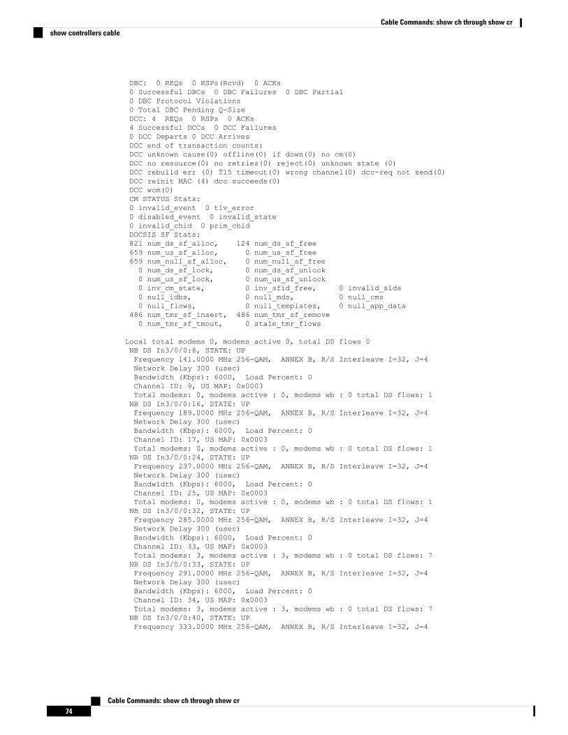
DBC: 0 REQs 0 RSPs(Rcvd) 0 ACKs0 Successful DBCs 0 DBC Failures 0 DBC Partial0 DBC Protocol Violations0 Total DBC Pending Q-SizeDCC: 4 REQs 0 RSPs 0 ACKs4 Successful DCCs 0 DCC Failures0 DCC Departs 0 DCC ArrivesDCC end of transaction counts:DCC unknown cause(0) offline(0) if down(0) no cm(0)DCC no resource(0) no retries(0) reject(0) unknown state (0)DCC rebuild err (0) T15 timeout(0) wrong channel(0) dcc-req not send(0)DCC reinit MAC (4) dcc succeeds(0)DCC wcm(0)CM STATUS Stats:0 invalid_event 0 tlv_error0 disabled_event 0 invalid_state0 invalid_chid 0 prim_chidDOCSIS SF Stats:821 num_ds_sf_alloc, 124 num_ds_sf_free659 num_us_sf_alloc, 0 num_us_sf_free659 num_null_sf_alloc, 0 num_null_sf_free0 num_ds_sf_lock, 0 num_ds_sf_unlock0 num_us_sf_lock, 0 num_us_sf_unlock0 inv_cm_state, 0 inv_sfid_free, 0 invalid_sids0 null_idbs, 0 null_mds, 0 null_cms0 null_flows, 0 null_templates, 0 null_app_data
486 num_tmr_sf_insert, 486 num_tmr_sf_remove0 num_tmr_sf_tmout, 0 stale_tmr_flows
Local total modems 0, modems active 0, total DS flows 0NB DS In3/0/0:8, STATE: UPFrequency 141.0000 MHz 256-QAM, ANNEX B, R/S Interleave I=32, J=4Network Delay 300 (usec)Bandwidth (Kbps): 6000, Load Percent: 0Channel ID: 9, US MAP: 0x0003Total modems: 0, modems active : 0, modems wb : 0 total DS flows: 1NB DS In3/0/0:16, STATE: UPFrequency 189.0000 MHz 256-QAM, ANNEX B, R/S Interleave I=32, J=4Network Delay 300 (usec)Bandwidth (Kbps): 6000, Load Percent: 0Channel ID: 17, US MAP: 0x0003Total modems: 0, modems active : 0, modems wb : 0 total DS flows: 1NB DS In3/0/0:24, STATE: UPFrequency 237.0000 MHz 256-QAM, ANNEX B, R/S Interleave I=32, J=4Network Delay 300 (usec)Bandwidth (Kbps): 6000, Load Percent: 0Channel ID: 25, US MAP: 0x0003Total modems: 0, modems active : 0, modems wb : 0 total DS flows: 1NB DS In3/0/0:32, STATE: UPFrequency 285.0000 MHz 256-QAM, ANNEX B, R/S Interleave I=32, J=4Network Delay 300 (usec)Bandwidth (Kbps): 6000, Load Percent: 0Channel ID: 33, US MAP: 0x0003Total modems: 3, modems active : 3, modems wb : 0 total DS flows: 7NB DS In3/0/0:33, STATE: UPFrequency 291.0000 MHz 256-QAM, ANNEX B, R/S Interleave I=32, J=4Network Delay 300 (usec)Bandwidth (Kbps): 6000, Load Percent: 0Channel ID: 34, US MAP: 0x0003Total modems: 3, modems active : 3, modems wb : 0 total DS flows: 7NB DS In3/0/0:40, STATE: UPFrequency 333.0000 MHz 256-QAM, ANNEX B, R/S Interleave I=32, J=4
Cable Commands: show ch through show cr74
Cable Commands: show ch through show crshow controllers cable
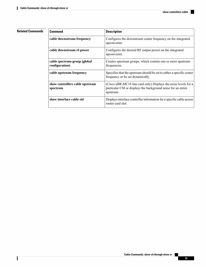
Related Commands DescriptionCommand
Configures the downstream center frequency on the integratedupconverter.
cable downstream frequency
Configures the desired RF output power on the integratedupconverter.
cable downstream rf-power
Creates spectrum groups, which contain one or more upstreamfrequencies.
cable spectrum-group (globalconfiguration)
Specifies that the upstream should be set to either a specific centerfrequency or be set dynamically.
cable upstream frequency
(Cisco uBR-MC16 line card only) Displays the noise levels for aparticular CM or displays the background noise for an entireupstream .
show controllers cable upstreamspectrum
Displays interface controller information for a specific cable accessrouter card slot.
show interface cable sid
Cable Commands: show ch through show cr75
Cable Commands: show ch through show crshow controllers cable
show controllers cable jibTo display the ASIC processor (JIB) register information on a cable interface on the Cisco CMTS router, usethe show controllers cable jibcommand in user EXEC or privileged EXEC mode.
show controllers cable {slot/cable-interface-indexslot/subslot/cable-interface-index} jib us-partial-reset
Syntax Description Slot where the line card resides.
• Cisco uBR7225VXR router—The valid value is 1 or 2.• Cisco uBR7246VXR router—The valid range is from 3 to 6.• Cisco uBR10012 router—The valid range is from 5 to 8.
slot
(Cisco uBR10012 only) Secondary slot number of the cable interface line card. Thevalid subslots are 0 or 1.
subslot
Downstream port of the Cisco uBR10-MC5X20 and Cisco uBR-MC28 line cards, orMAC domain index of the Cisco UBR-MC20X20V and Cisco uBR-MC3GX60V linecards.
• Cisco uBR7225VXR and Cisco uBR7246VXR routers—The valid port value is0 or 1.
• Cisco uBR10012 router—The valid range for the Cisco UBR-MC20X20V andCisco uBR-MC5X20 line cards is from 0 to 4. The valid range for the CiscouBR-MC3GX60V line card is from 0 to 14.
cable-interface-index
Displays JIB register information.jib
Displays JIB3 upstream partial reset data.us-partial-reset
Command ModesUser EXEC (>) or
Privileged EXEC (#)
Command History ModificationRelease
This command was introduced.12.2(33)SCF
This command is not supported on the Cisco cBR Series Converged Broadband Router.IOS-XE3.15.0S
Usage Guidelines The show controllers cable jib command displays the packet capture buffers retrieved during the partialreset. It displays all of the capture buffers associated with the last partial reset event and also other informationuseful for determining the Partial Reset state.
Examples The following is a sample output of the show controllers cable jib command:Router# show controllers cable 5/0/0 jib us-partial-reset
Cable Commands: show ch through show cr76
Cable Commands: show ch through show crshow controllers cable jib
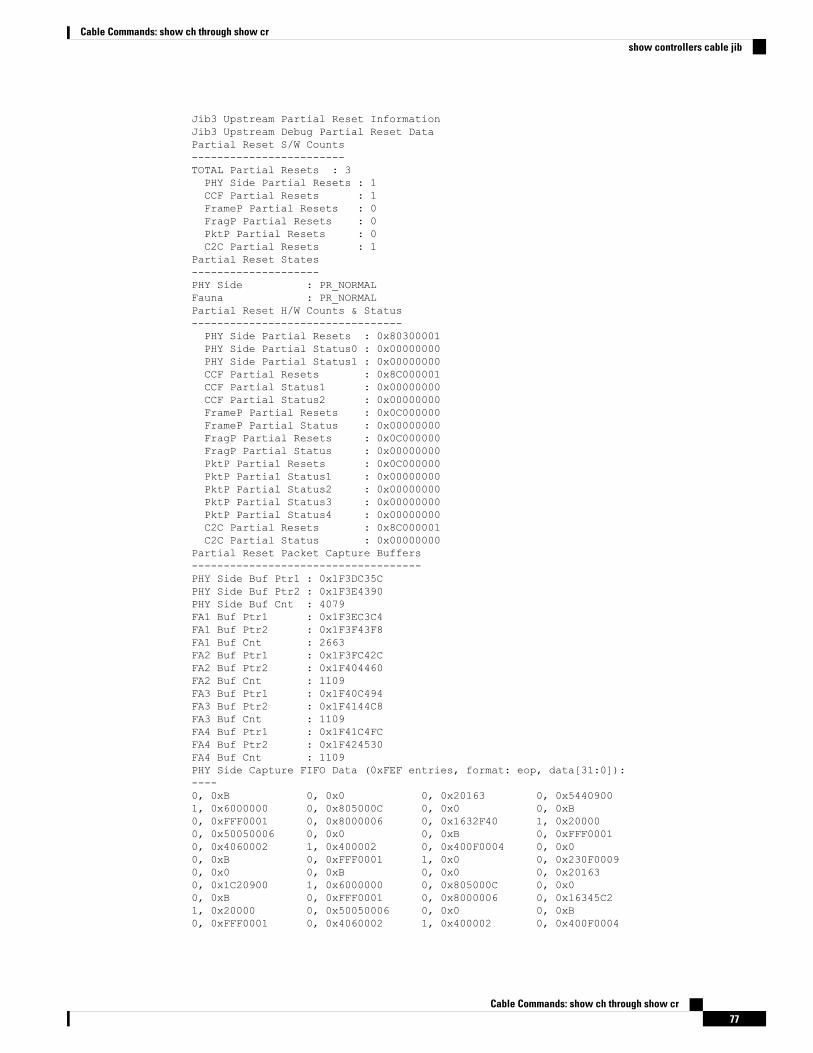
Jib3 Upstream Partial Reset InformationJib3 Upstream Debug Partial Reset DataPartial Reset S/W Counts------------------------TOTAL Partial Resets : 3PHY Side Partial Resets : 1CCF Partial Resets : 1FrameP Partial Resets : 0FragP Partial Resets : 0PktP Partial Resets : 0C2C Partial Resets : 1
Partial Reset States--------------------PHY Side : PR_NORMALFauna : PR_NORMALPartial Reset H/W Counts & Status---------------------------------PHY Side Partial Resets : 0x80300001PHY Side Partial Status0 : 0x00000000PHY Side Partial Status1 : 0x00000000CCF Partial Resets : 0x8C000001CCF Partial Status1 : 0x00000000CCF Partial Status2 : 0x00000000FrameP Partial Resets : 0x0C000000FrameP Partial Status : 0x00000000FragP Partial Resets : 0x0C000000FragP Partial Status : 0x00000000PktP Partial Resets : 0x0C000000PktP Partial Status1 : 0x00000000PktP Partial Status2 : 0x00000000PktP Partial Status3 : 0x00000000PktP Partial Status4 : 0x00000000C2C Partial Resets : 0x8C000001C2C Partial Status : 0x00000000
Partial Reset Packet Capture Buffers------------------------------------PHY Side Buf Ptr1 : 0x1F3DC35CPHY Side Buf Ptr2 : 0x1F3E4390PHY Side Buf Cnt : 4079FA1 Buf Ptr1 : 0x1F3EC3C4FA1 Buf Ptr2 : 0x1F3F43F8FA1 Buf Cnt : 2663FA2 Buf Ptr1 : 0x1F3FC42CFA2 Buf Ptr2 : 0x1F404460FA2 Buf Cnt : 1109FA3 Buf Ptr1 : 0x1F40C494FA3 Buf Ptr2 : 0x1F4144C8FA3 Buf Cnt : 1109FA4 Buf Ptr1 : 0x1F41C4FCFA4 Buf Ptr2 : 0x1F424530FA4 Buf Cnt : 1109PHY Side Capture FIFO Data (0xFEF entries, format: eop, data[31:0]):----0, 0xB 0, 0x0 0, 0x20163 0, 0x54409001, 0x6000000 0, 0x805000C 0, 0x0 0, 0xB0, 0xFFF0001 0, 0x8000006 0, 0x1632F40 1, 0x200000, 0x50050006 0, 0x0 0, 0xB 0, 0xFFF00010, 0x4060002 1, 0x400002 0, 0x400F0004 0, 0x00, 0xB 0, 0xFFF0001 1, 0x0 0, 0x230F00090, 0x0 0, 0xB 0, 0x0 0, 0x201630, 0x1C20900 1, 0x6000000 0, 0x805000C 0, 0x00, 0xB 0, 0xFFF0001 0, 0x8000006 0, 0x16345C21, 0x20000 0, 0x50050006 0, 0x0 0, 0xB0, 0xFFF0001 0, 0x4060002 1, 0x400002 0, 0x400F0004
Cable Commands: show ch through show cr77
Cable Commands: show ch through show crshow controllers cable jib

0, 0x0 0, 0xB 0, 0xFFF0001 1, 0x00, 0x230F0009 0, 0x0 0, 0xB 0, 0x00, 0x20163 0, 0x8470900 1, 0x6000000 0, 0x805000C0, 0x0 0, 0xB 0, 0xFFF0001 0, 0x80000060, 0x1637402 1, 0x20000 0, 0x50050006 0, 0x00, 0xB 0, 0xFFF0001 0, 0x4060002 1, 0x4000020, 0x400F0004 0, 0x0 0, 0xB 0, 0xFFF00011, 0x0 0, 0x230F0009 0, 0x0 0, 0xB0, 0x0 0, 0x20163 0, 0x6840900 1, 0x60000000, 0x805000C 0, 0x0 0, 0xB 0, 0xFFF00010, 0x8000006 0, 0x1639C03 1, 0x20000 0, 0x500500060, 0x0 0, 0xB 0, 0xFFF0001 0, 0x40600021, 0x400002 0, 0x400F0004 0, 0x0 0, 0xB0, 0xFFF0001 1, 0x0 0, 0x230F0009 0, 0x00, 0xB 0, 0x0 0, 0x20163 0, 0xE8509001, 0x6000000 0, 0x1C06002E 0, 0x0 0, 0x50, 0x10004 0, 0x1C 0, 0xA1D0005 0, 0xE4E8F70, 0x1E6BFB 0, 0x794000A 0, 0x830301 0, 0x40080010, 0x800F5C6 0, 0x3D30B06 0, 0x44080 0, 0xF8FFFFF1, 0xFF2FFFF 0, 0x400F0004 0, 0x0 0, 0x50, 0x10004 1, 0x10000 0, 0x1C06002E 0, 0x00, 0x1 0, 0x10004 0, 0x1C 0, 0xA1D00050, 0xE4E8F6 0, 0x23BE85 0, 0x906000A 0, 0xA603010, 0x4000001 0, 0x100BDD7 0, 0xE90B06 0, 0x243000, 0x220000 1, 0x15A0000 0, 0x400F0004 0, 0x00, 0x1 0, 0x10004 1, 0x10000 0, 0x805000C0, 0x0 0, 0xB 0, 0xFFF0001 0, 0x800001E0, 0x1651CB2 1, 0x10000 0, 0x50050006 0, 0x00, 0xB 0, 0xFFF0001 0, 0x41E0001 1, 0xC3100010, 0x400F0004 0, 0x0 0, 0xB 0, 0xFFF00011, 0x0 0, 0x230F0009 0, 0x0 0, 0xB0, 0x0 0, 0x10165 0, 0xE560A00 1, 0xE0000000, 0x805000C 0, 0x0 0, 0xB 0, 0xFFF00010, 0x800001E 0, 0x165229C 1, 0x10000 0, 0x500500060, 0x0 0, 0xB 0, 0xFFF0001 0, 0x41E00011, 0xC310001 0, 0x400F0004 0, 0x0 0, 0xB0, 0xFFF0001 1, 0x0 0, 0x230F0009 0, 0x00, 0xB 0, 0x0 0, 0x10165 0, 0x4940A001, 0xE000000 0, 0x805000C 0, 0x0 0, 0xB0, 0xFFF0001 0, 0x800001E 0, 0x1652647 1, 0x100000, 0x50050006 0, 0x0 0, 0xB 0, 0xFFF00010, 0x41E0001 1, 0xC310001 0, 0x400F0004 0, 0x00, 0xB 0, 0xFFF0001 1, 0x0 0, 0x230F00090, 0x0 0, 0xB 0, 0x0 0, 0x101650, 0x2560A00 1, 0xE000000 0, 0x805000C 0, 0x00, 0xB 0, 0xFFF0001 0, 0x800001E 0, 0x16534241, 0x10000 0, 0x50050006 0, 0x0 0, 0xB0, 0xFFF0001 0, 0x41E0001 1, 0xC310001 0, 0x400F00040, 0x0 0, 0xB 0, 0xFFF0001 1, 0x00, 0x230F0009 0, 0x0 0, 0xB 0, 0x00, 0x10165 0, 0x1D70A00 1, 0xE000000 0, 0x805000C0, 0x0 0, 0xB 0, 0xFFF0001 0, 0x800001E0, 0x1656396 1, 0x10000 0, 0x50050006 0, 0x00, 0xB 0, 0xFFF0001 0, 0x41E0001 1, 0xC3100010, 0x400F0004 0, 0x0 0, 0xB 0, 0xFFF00011, 0x0 0, 0x230F0009 0, 0x0 0, 0xB0, 0x0 0, 0x10165 0, 0x1A0A00 1, 0xE0000000, 0x805000C 0, 0x0 0, 0xB 0, 0xFFF00010, 0x800001E 0, 0x16591E8 1, 0x10000 0, 0x500500060, 0x0 0, 0xB 0, 0xFFF0001 0, 0x41E00011, 0xC310001 0, 0x400F0004 0, 0x0 0, 0xB0, 0xFFF0001 1, 0x0 0, 0x230F0009 0, 0x00, 0xB 0, 0x0 0, 0x10165 0, 0xDC0A001, 0xE000000 0, 0x805000C 0, 0x0 0, 0xB
Cable Commands: show ch through show cr78
Cable Commands: show ch through show crshow controllers cable jib
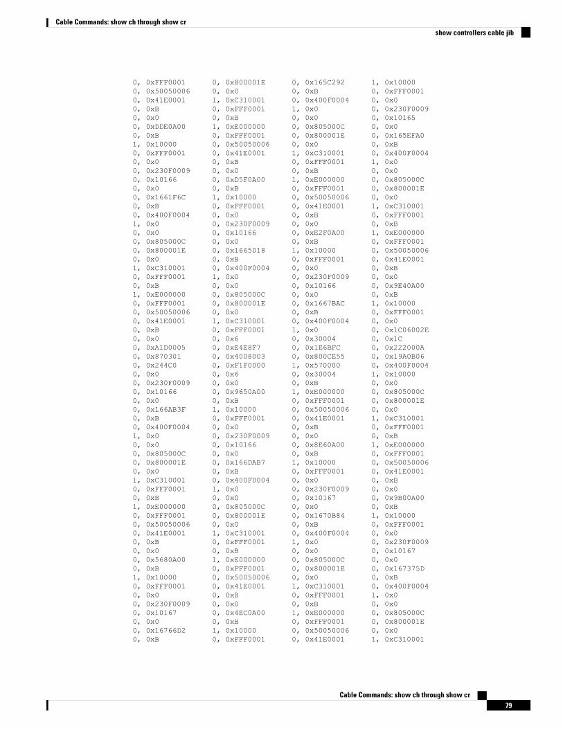
0, 0xFFF0001 0, 0x800001E 0, 0x165C292 1, 0x100000, 0x50050006 0, 0x0 0, 0xB 0, 0xFFF00010, 0x41E0001 1, 0xC310001 0, 0x400F0004 0, 0x00, 0xB 0, 0xFFF0001 1, 0x0 0, 0x230F00090, 0x0 0, 0xB 0, 0x0 0, 0x101650, 0xDDE0A00 1, 0xE000000 0, 0x805000C 0, 0x00, 0xB 0, 0xFFF0001 0, 0x800001E 0, 0x165EFA01, 0x10000 0, 0x50050006 0, 0x0 0, 0xB0, 0xFFF0001 0, 0x41E0001 1, 0xC310001 0, 0x400F00040, 0x0 0, 0xB 0, 0xFFF0001 1, 0x00, 0x230F0009 0, 0x0 0, 0xB 0, 0x00, 0x10166 0, 0xD5F0A00 1, 0xE000000 0, 0x805000C0, 0x0 0, 0xB 0, 0xFFF0001 0, 0x800001E0, 0x1661F6C 1, 0x10000 0, 0x50050006 0, 0x00, 0xB 0, 0xFFF0001 0, 0x41E0001 1, 0xC3100010, 0x400F0004 0, 0x0 0, 0xB 0, 0xFFF00011, 0x0 0, 0x230F0009 0, 0x0 0, 0xB0, 0x0 0, 0x10166 0, 0xE2F0A00 1, 0xE0000000, 0x805000C 0, 0x0 0, 0xB 0, 0xFFF00010, 0x800001E 0, 0x1665018 1, 0x10000 0, 0x500500060, 0x0 0, 0xB 0, 0xFFF0001 0, 0x41E00011, 0xC310001 0, 0x400F0004 0, 0x0 0, 0xB0, 0xFFF0001 1, 0x0 0, 0x230F0009 0, 0x00, 0xB 0, 0x0 0, 0x10166 0, 0x9E40A001, 0xE000000 0, 0x805000C 0, 0x0 0, 0xB0, 0xFFF0001 0, 0x800001E 0, 0x1667BAC 1, 0x100000, 0x50050006 0, 0x0 0, 0xB 0, 0xFFF00010, 0x41E0001 1, 0xC310001 0, 0x400F0004 0, 0x00, 0xB 0, 0xFFF0001 1, 0x0 0, 0x1C06002E0, 0x0 0, 0x6 0, 0x30004 0, 0x1C0, 0xA1D0005 0, 0xE4E8F7 0, 0x1E6BFC 0, 0x222000A0, 0x870301 0, 0x4008003 0, 0x800CE55 0, 0x19A0B060, 0x244C0 0, 0xF1F0000 1, 0x570000 0, 0x400F00040, 0x0 0, 0x6 0, 0x30004 1, 0x100000, 0x230F0009 0, 0x0 0, 0xB 0, 0x00, 0x10166 0, 0x9650A00 1, 0xE000000 0, 0x805000C0, 0x0 0, 0xB 0, 0xFFF0001 0, 0x800001E0, 0x166AB3F 1, 0x10000 0, 0x50050006 0, 0x00, 0xB 0, 0xFFF0001 0, 0x41E0001 1, 0xC3100010, 0x400F0004 0, 0x0 0, 0xB 0, 0xFFF00011, 0x0 0, 0x230F0009 0, 0x0 0, 0xB0, 0x0 0, 0x10166 0, 0x8E60A00 1, 0xE0000000, 0x805000C 0, 0x0 0, 0xB 0, 0xFFF00010, 0x800001E 0, 0x166DAB7 1, 0x10000 0, 0x500500060, 0x0 0, 0xB 0, 0xFFF0001 0, 0x41E00011, 0xC310001 0, 0x400F0004 0, 0x0 0, 0xB0, 0xFFF0001 1, 0x0 0, 0x230F0009 0, 0x00, 0xB 0, 0x0 0, 0x10167 0, 0x9B00A001, 0xE000000 0, 0x805000C 0, 0x0 0, 0xB0, 0xFFF0001 0, 0x800001E 0, 0x1670B84 1, 0x100000, 0x50050006 0, 0x0 0, 0xB 0, 0xFFF00010, 0x41E0001 1, 0xC310001 0, 0x400F0004 0, 0x00, 0xB 0, 0xFFF0001 1, 0x0 0, 0x230F00090, 0x0 0, 0xB 0, 0x0 0, 0x101670, 0x5680A00 1, 0xE000000 0, 0x805000C 0, 0x00, 0xB 0, 0xFFF0001 0, 0x800001E 0, 0x167375D1, 0x10000 0, 0x50050006 0, 0x0 0, 0xB0, 0xFFF0001 0, 0x41E0001 1, 0xC310001 0, 0x400F00040, 0x0 0, 0xB 0, 0xFFF0001 1, 0x00, 0x230F0009 0, 0x0 0, 0xB 0, 0x00, 0x10167 0, 0x4EC0A00 1, 0xE000000 0, 0x805000C0, 0x0 0, 0xB 0, 0xFFF0001 0, 0x800001E0, 0x16766D2 1, 0x10000 0, 0x50050006 0, 0x00, 0xB 0, 0xFFF0001 0, 0x41E0001 1, 0xC310001
Cable Commands: show ch through show cr79
Cable Commands: show ch through show crshow controllers cable jib
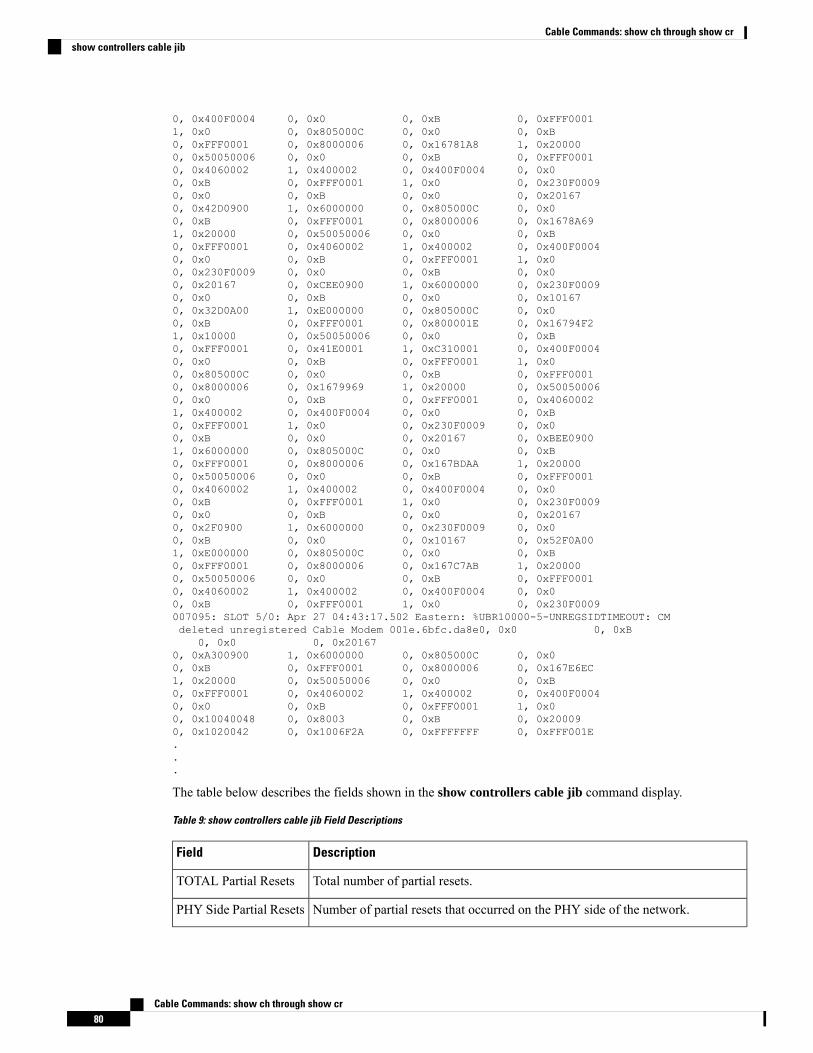
0, 0x400F0004 0, 0x0 0, 0xB 0, 0xFFF00011, 0x0 0, 0x805000C 0, 0x0 0, 0xB0, 0xFFF0001 0, 0x8000006 0, 0x16781A8 1, 0x200000, 0x50050006 0, 0x0 0, 0xB 0, 0xFFF00010, 0x4060002 1, 0x400002 0, 0x400F0004 0, 0x00, 0xB 0, 0xFFF0001 1, 0x0 0, 0x230F00090, 0x0 0, 0xB 0, 0x0 0, 0x201670, 0x42D0900 1, 0x6000000 0, 0x805000C 0, 0x00, 0xB 0, 0xFFF0001 0, 0x8000006 0, 0x1678A691, 0x20000 0, 0x50050006 0, 0x0 0, 0xB0, 0xFFF0001 0, 0x4060002 1, 0x400002 0, 0x400F00040, 0x0 0, 0xB 0, 0xFFF0001 1, 0x00, 0x230F0009 0, 0x0 0, 0xB 0, 0x00, 0x20167 0, 0xCEE0900 1, 0x6000000 0, 0x230F00090, 0x0 0, 0xB 0, 0x0 0, 0x101670, 0x32D0A00 1, 0xE000000 0, 0x805000C 0, 0x00, 0xB 0, 0xFFF0001 0, 0x800001E 0, 0x16794F21, 0x10000 0, 0x50050006 0, 0x0 0, 0xB0, 0xFFF0001 0, 0x41E0001 1, 0xC310001 0, 0x400F00040, 0x0 0, 0xB 0, 0xFFF0001 1, 0x00, 0x805000C 0, 0x0 0, 0xB 0, 0xFFF00010, 0x8000006 0, 0x1679969 1, 0x20000 0, 0x500500060, 0x0 0, 0xB 0, 0xFFF0001 0, 0x40600021, 0x400002 0, 0x400F0004 0, 0x0 0, 0xB0, 0xFFF0001 1, 0x0 0, 0x230F0009 0, 0x00, 0xB 0, 0x0 0, 0x20167 0, 0xBEE09001, 0x6000000 0, 0x805000C 0, 0x0 0, 0xB0, 0xFFF0001 0, 0x8000006 0, 0x167BDAA 1, 0x200000, 0x50050006 0, 0x0 0, 0xB 0, 0xFFF00010, 0x4060002 1, 0x400002 0, 0x400F0004 0, 0x00, 0xB 0, 0xFFF0001 1, 0x0 0, 0x230F00090, 0x0 0, 0xB 0, 0x0 0, 0x201670, 0x2F0900 1, 0x6000000 0, 0x230F0009 0, 0x00, 0xB 0, 0x0 0, 0x10167 0, 0x52F0A001, 0xE000000 0, 0x805000C 0, 0x0 0, 0xB0, 0xFFF0001 0, 0x8000006 0, 0x167C7AB 1, 0x200000, 0x50050006 0, 0x0 0, 0xB 0, 0xFFF00010, 0x4060002 1, 0x400002 0, 0x400F0004 0, 0x00, 0xB 0, 0xFFF0001 1, 0x0 0, 0x230F0009007095: SLOT 5/0: Apr 27 04:43:17.502 Eastern: %UBR10000-5-UNREGSIDTIMEOUT: CMdeleted unregistered Cable Modem 001e.6bfc.da8e0, 0x0 0, 0xB
0, 0x0 0, 0x201670, 0xA300900 1, 0x6000000 0, 0x805000C 0, 0x00, 0xB 0, 0xFFF0001 0, 0x8000006 0, 0x167E6EC1, 0x20000 0, 0x50050006 0, 0x0 0, 0xB0, 0xFFF0001 0, 0x4060002 1, 0x400002 0, 0x400F00040, 0x0 0, 0xB 0, 0xFFF0001 1, 0x00, 0x10040048 0, 0x8003 0, 0xB 0, 0x200090, 0x1020042 0, 0x1006F2A 0, 0xFFFFFFF 0, 0xFFF001E...
The table below describes the fields shown in the show controllers cable jib command display.
Table 9: show controllers cable jib Field Descriptions
DescriptionField
Total number of partial resets.TOTAL Partial Resets
Number of partial resets that occurred on the PHY side of the network.PHY Side Partial Resets
Cable Commands: show ch through show cr80
Cable Commands: show ch through show crshow controllers cable jib
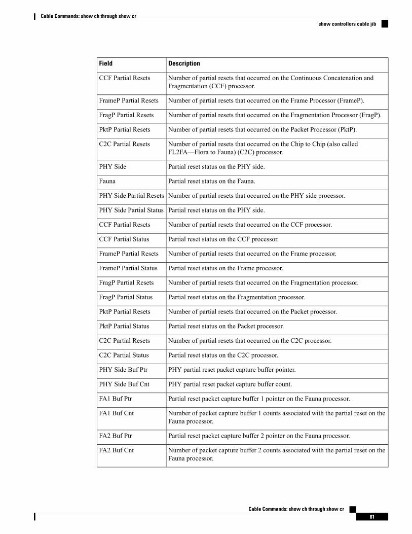
DescriptionField
Number of partial resets that occurred on the Continuous Concatenation andFragmentation (CCF) processor.
CCF Partial Resets
Number of partial resets that occurred on the Frame Processor (FrameP).FrameP Partial Resets
Number of partial resets that occurred on the Fragmentation Processor (FragP).FragP Partial Resets
Number of partial resets that occurred on the Packet Processor (PktP).PktP Partial Resets
Number of partial resets that occurred on the Chip to Chip (also calledFL2FA—Flora to Fauna) (C2C) processor.
C2C Partial Resets
Partial reset status on the PHY side.PHY Side
Partial reset status on the Fauna.Fauna
Number of partial resets that occurred on the PHY side processor.PHY Side Partial Resets
Partial reset status on the PHY side.PHY Side Partial Status
Number of partial resets that occurred on the CCF processor.CCF Partial Resets
Partial reset status on the CCF processor.CCF Partial Status
Number of partial resets that occurred on the Frame processor.FrameP Partial Resets
Partial reset status on the Frame processor.FrameP Partial Status
Number of partial resets that occurred on the Fragmentation processor.FragP Partial Resets
Partial reset status on the Fragmentation processor.FragP Partial Status
Number of partial resets that occurred on the Packet processor.PktP Partial Resets
Partial reset status on the Packet processor.PktP Partial Status
Number of partial resets that occurred on the C2C processor.C2C Partial Resets
Partial reset status on the C2C processor.C2C Partial Status
PHY partial reset packet capture buffer pointer.PHY Side Buf Ptr
PHY partial reset packet capture buffer count.PHY Side Buf Cnt
Partial reset packet capture buffer 1 pointer on the Fauna processor.FA1 Buf Ptr
Number of packet capture buffer 1 counts associated with the partial reset on theFauna processor.
FA1 Buf Cnt
Partial reset packet capture buffer 2 pointer on the Fauna processor.FA2 Buf Ptr
Number of packet capture buffer 2 counts associated with the partial reset on theFauna processor.
FA2 Buf Cnt
Cable Commands: show ch through show cr81
Cable Commands: show ch through show crshow controllers cable jib
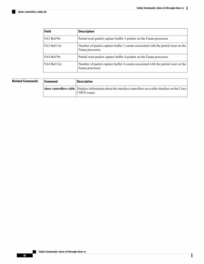
DescriptionField
Partial reset packet capture buffer 3 pointer on the Fauna processor.FA3 Buf Ptr
Number of packet capture buffer 3 counts associated with the partial reset on theFauna processor.
FA3 Buf Cnt
Partial reset packet capture buffer 4 pointer on the Fauna processor.FA4 Buf Ptr
Number of packet capture buffer 4 counts associated with the partial reset on theFauna processor.
FA4 Buf Cnt
Related Commands DescriptionCommand
Displays information about the interface controllers on a cable interface on the CiscoCMTS router.
show controllers cable
Cable Commands: show ch through show cr82
Cable Commands: show ch through show crshow controllers cable jib
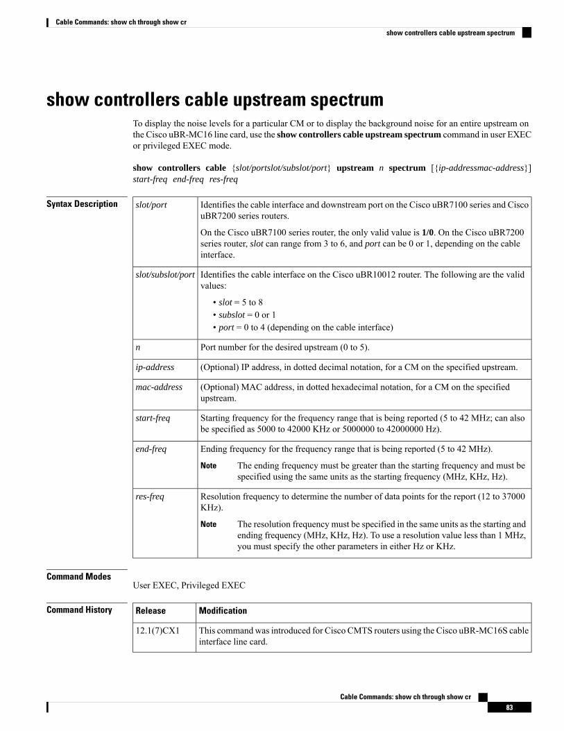
show controllers cable upstream spectrumTo display the noise levels for a particular CM or to display the background noise for an entire upstream onthe Cisco uBR-MC16 line card, use the show controllers cable upstream spectrum command in user EXECor privileged EXEC mode.
show controllers cable {slot/portslot/subslot/port} upstream n spectrum [{ip-addressmac-address}]start-freq end-freq res-freq
Syntax Description Identifies the cable interface and downstream port on the Cisco uBR7100 series and CiscouBR7200 series routers.
On the Cisco uBR7100 series router, the only valid value is 1/0. On the Cisco uBR7200series router, slot can range from 3 to 6, and port can be 0 or 1, depending on the cableinterface.
slot/port
Identifies the cable interface on the Cisco uBR10012 router. The following are the validvalues:
• slot = 5 to 8• subslot = 0 or 1• port = 0 to 4 (depending on the cable interface)
slot/subslot/port
Port number for the desired upstream (0 to 5).n
(Optional) IP address, in dotted decimal notation, for a CM on the specified upstream.ip-address
(Optional) MAC address, in dotted hexadecimal notation, for a CM on the specifiedupstream.
mac-address
Starting frequency for the frequency range that is being reported (5 to 42 MHz; can alsobe specified as 5000 to 42000 KHz or 5000000 to 42000000 Hz).
start-freq
Ending frequency for the frequency range that is being reported (5 to 42 MHz).
The ending frequency must be greater than the starting frequency and must bespecified using the same units as the starting frequency (MHz, KHz, Hz).
Note
end-freq
Resolution frequency to determine the number of data points for the report (12 to 37000KHz).
The resolution frequency must be specified in the same units as the starting andending frequency (MHz, KHz, Hz). To use a resolution value less than 1 MHz,you must specify the other parameters in either Hz or KHz.
Note
res-freq
Command ModesUser EXEC, Privileged EXEC
Command History ModificationRelease
This commandwas introduced for Cisco CMTS routers using the Cisco uBR-MC16S cableinterface line card.
12.1(7)CX1
Cable Commands: show ch through show cr83
Cable Commands: show ch through show crshow controllers cable upstream spectrum
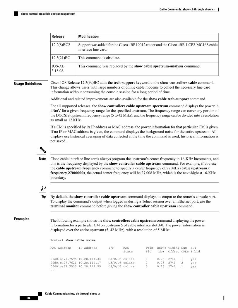
ModificationRelease
Support was added for the Cisco uBR10012 router and the Cisco uBR-LCP2-MC16S cableinterface line card.
12.2(8)BC2
This command is obsolete.12.3(21)BC
This command was replaced by the show cable spectrum-analysis command.IOS-XE3.15.0S
Usage Guidelines Cisco IOS Release 12.3(9a)BC adds the tech-support keyword to the show controllers cable command.This change allows users with large numbers of online cable modems to collect the necessary line cardinformation without consuming the console session for a long period of time.
Additional and related improvements are also available for the show cable tech-support command.
For all supported releases, the show controllers cable upstream spectrum command displays the power indBmV for a given frequency range for the specified upstream. The frequency range can cover any portion ofthe DOCSIS upstream frequency range (5 to 42MHz), and the frequency range can be divided into a resolutionas small as 12 KHz.
If a CM is specified by its IP address or MAC address, the power information for that particular CM is given.If no IP or MAC address is given, the command displays the background noise for the entire upstream. Alldisplays use historical averaging of data collected at the time the command is used; historical information isnot saved.
Cisco cable interface line cards always program the upstream’s center frequency in 16-KHz increments, andthis is the frequency displayed by the show controller cable upstream command. For example, if you usethe cable upstream frequency command to specify a center frequency of 27 MHz (cable upstream xfrequency 27000000), the actual center frequency will be 27.008 MHz, which is the next-highest 16-KHzboundary.
Note
By default, the show controller cable upstream command displays its output to the router’s console port.To display the command’s output when logged in during a Telnet session over an Ethernet port, use theterminal monitor command before giving the show controller cable upstream command.
Tip
Examples The following example shows the show controllers cable upstream command displaying the powerinformation for a particular CM on upstream 5 of cable interface slot 3/0. The power information isdisplayed over the entire upstream (5–42 MHz), with a resolution of 5 MHz:
Router# show cable modem
MAC Address IP Address I/F MAC Prim RxPwr Timing Num BPIState Sid (db) Offset CPEs Enbld
...00d0.ba77.7595 10.20.114.34 C3/0/U5 online 1 0.25 2740 1 yes00d0.ba77.7621 10.20.114.17 C3/0/U5 online 2 0.25 2740 2 yes00d0.ba77.7533 10.20.114.55 C3/0/U5 online 3 0.25 2740 1 yes...
Cable Commands: show ch through show cr84
Cable Commands: show ch through show crshow controllers cable upstream spectrum
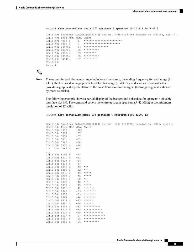
Router# show controllers cable 3/0 upstream 5 spectrum 10.20.114.34 5 42 5
02:16:49: Spectrum DATA(@0x4B060004) for u5: 4995-41991KHz(resolution 4992KHz, sid 1):02:16:49: Freq(KHz) dBmV Chart02:16:49: 4995 : -5 *************************02:16:49: 9987 : -7 ************************02:16:49: 14979: -24 ****************02:16:49: 19971: -35 **********02:16:49: 24963: -39 ********02:16:49: 29955: -35 **********02:16:49: 34947: -37 *********02:16:49:Router#
The output for each frequency range includes a time-stamp, the ending frequency for each range (inKHz), the historical average power level for that range (in dBmV), and a series of asterisks thatprovides a graphical representation of the noise floor level for the signal (a stronger signal is indicatedby more asterisks).
Note
The following example shows a partial display of the background noise data for upstream 4 of cableinterface slot 6/0. The command covers the entire upstream spectrum (5–42 MHz) at the minimumresolution of 12 KHz.
Router# show controller cable 6/0 upstream 4 spectrum 5000 42000 12
02:15:54: Spectrum DATA(@0x4B060004) for u5: 4995-41991KHz(resolution 12KHz, sid 1):02:15:54: Freq(KHz) dBmV Chart02:15:54: 4995 : -10002:15:54: 5007 : -6702:15:54: 5019 : -6702:15:54: 5031 : -6702:15:54: 5043 : -6402:15:54: 5055 : -6402:15:54: 5067 : -61...02:15:54: 8199 : -6702:15:54: 8211 : -6102:15:54: 8223 : -6402:15:54: 8235 : -5702:15:54: 8247 : -49 ***02:15:54: 8259 : -52 **02:15:54: 8271 : -46 *****02:15:54: 8283 : -45 *****02:15:54: 8295 : -52 **02:15:54: 8307 : -48 ****02:15:54: 8319 : -45 *****02:15:54: 8331 : -41 *******02:15:54: 8343 : -39 ********02:15:54: 8355 : -39 ********02:15:54: 8367 : -40 ********02:15:54: 8379 : -43 ******02:15:54: 8391 : -44 ******02:15:54: 8403 : -33 ***********02:15:54: 8415 : -32 ************02:15:54: 8427 : -30 *************02:15:54: 8439 : -27 **************02:15:54: 8451 : -28 **************02:15:54: 8463 : -36 **********
Cable Commands: show ch through show cr85
Cable Commands: show ch through show crshow controllers cable upstream spectrum
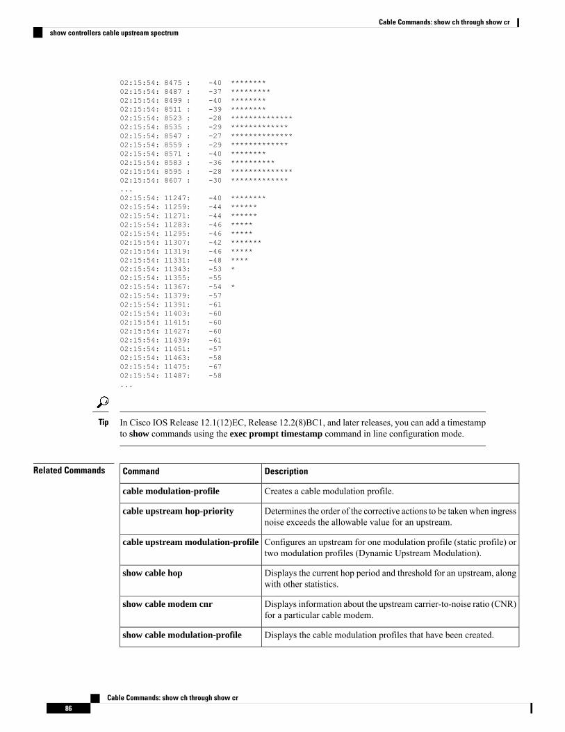
02:15:54: 8475 : -40 ********02:15:54: 8487 : -37 *********02:15:54: 8499 : -40 ********02:15:54: 8511 : -39 ********02:15:54: 8523 : -28 **************02:15:54: 8535 : -29 *************02:15:54: 8547 : -27 **************02:15:54: 8559 : -29 *************02:15:54: 8571 : -40 ********02:15:54: 8583 : -36 **********02:15:54: 8595 : -28 **************02:15:54: 8607 : -30 *************...02:15:54: 11247: -40 ********02:15:54: 11259: -44 ******02:15:54: 11271: -44 ******02:15:54: 11283: -46 *****02:15:54: 11295: -46 *****02:15:54: 11307: -42 *******02:15:54: 11319: -46 *****02:15:54: 11331: -48 ****02:15:54: 11343: -53 *02:15:54: 11355: -5502:15:54: 11367: -54 *02:15:54: 11379: -5702:15:54: 11391: -6102:15:54: 11403: -6002:15:54: 11415: -6002:15:54: 11427: -6002:15:54: 11439: -6102:15:54: 11451: -5702:15:54: 11463: -5802:15:54: 11475: -6702:15:54: 11487: -58...
In Cisco IOS Release 12.1(12)EC, Release 12.2(8)BC1, and later releases, you can add a timestampto show commands using the exec prompt timestamp command in line configuration mode.
Tip
Related Commands DescriptionCommand
Creates a cable modulation profile.cable modulation-profile
Determines the order of the corrective actions to be taken when ingressnoise exceeds the allowable value for an upstream.
cable upstream hop-priority
Configures an upstream for one modulation profile (static profile) ortwo modulation profiles (Dynamic Upstream Modulation).
cable upstream modulation-profile
Displays the current hop period and threshold for an upstream, alongwith other statistics.
show cable hop
Displays information about the upstream carrier-to-noise ratio (CNR)for a particular cable modem.
show cable modem cnr
Displays the cable modulation profiles that have been created.show cable modulation-profile
Cable Commands: show ch through show cr86
Cable Commands: show ch through show crshow controllers cable upstream spectrum

DescriptionCommand
Displays detailed statistics for the cable interface.show controllers cable
Cable Commands: show ch through show cr87
Cable Commands: show ch through show crshow controllers cable upstream spectrum
show controllers clock-referenceTo display hardware information, register values, and current counters for the TCC+ card or the Cisco cableclock card, use the show controllers clock-reference command in privileged EXEC mode.
show controllers clock-reference
Syntax Description This command has no keywords or arguments.
Command ModesPrivileged EXEC
Command History ModificationRelease
This command was introduced.12.1(1a)T1
This command was supported on the EC train.12.1(2)EC1
This command was supported for the TCC+ card on Cisco uBR10012 routers.12.2(2)XF
Support was added to the Release 12.2 BC train.12.2(4)BC1
Usage Guidelines To reset the counters that are displayed with the show controllers clock-reference command, use the cableclock clear-counters command.
This command is not applicable on the SC train.Note
This command supports the Cisco CMTS clock feature set, which provides a synchronized clock for improvedVoice-over-IP (VoIP) operations. The clock feature set requires one of the following configurations:
• A Cisco uBR10012 router with one or two TCC+ cards that are connected to an external national clocksource.
• A Cisco uBR7246 VXR router using a Cisco uBR-MC16S, Cisco uBR-MC16E, Cisco uBR-MC28C, orCisco uBR-MC28C-BNC cable interface line card. The router must also be equipped with a Cisco cableclock card and be running Cisco IOS 12.1(1a)T1, 12.1(2)EC1, or a later release. The Cisco cable clockcard should be connected to an external national clock source.
Only these cable interface cards support the external clock card reference from a clock card to distribute thatsignal to CMs or set-top boxes (STBs) attached to the specific network segments. You can use other cableinterface cards, such as the Cisco uBR-MC16C, with the clock card, but these other cable interfaces will notsynchronize their downstream SYNC messages with the external clock source.
Each CM or STB must also support VoIP applications and the clock feature set. For example, the CiscouBR924, running Cisco IOS Release 12.0(7)T or later, supports clock card feature automatically.
Examples The following is sample output from the show controllers clock-reference command for a CiscouBR7246 VXR router with a national clock card:
Cable Commands: show ch through show cr88
Cable Commands: show ch through show crshow controllers clock-reference
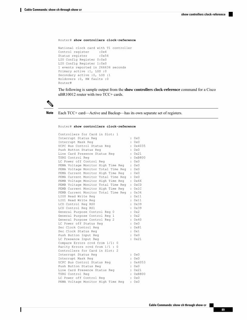
Router# show controllers clock-reference
National clock card with T1 controllerControl register :0x4Status register :0x54LIU Config Register 0:0x0LIU Config Register 1:0x01 events reported in 266636 secondsPrimary active :1, LOS :0Secondary active :0, LOS :1Holdovers :0, HW faults :0Router#
The following is sample output from the show controllers clock-reference command for a CiscouBR10012 router with two TCC+ cards.
Each TCC+ card—Active and Backup—has its own separate set of registers.Note
Router# show controllers clock-reference
Controllers for Card in Slot: 1Interrupt Status Reg : 0x0Interrupt Mask Reg : 0x0UCPC Bus Control Status Reg : 0x4035Push Button Status Reg : 0x0Line Card Presence Status Reg : 0x21TSRG Control Reg : 0xB800LC Power off Control Reg : 0x0PEMA Voltage Monitor High Time Reg : 0x0PEMA Voltage Monitor Total Time Reg : 0x0PEMA Current Monitor High Time Reg : 0x0PEMA Current Monitor Total Time Reg : 0x0PEMB Voltage Monitor High Time Reg : 0x66PEMB Voltage Monitor Total Time Reg : 0xCDPEMB Current Monitor High Time Reg : 0x1CPEMB Current Monitor Total Time Reg : 0x34LIU0 Read Write Reg : 0x11LIU1 Read Write Reg : 0x11LCD Control Reg RS0 : 0x39LCD Control Reg RS1 : 0x39General Purpose Control Reg 0 : 0x2General Purpose Control Reg 1 : 0x2General Purpose Control Reg 2 : 0x40LC Power off Status Reg : 0x0Sec Clock Control Reg : 0x81Sec Clock Status Reg : 0x1Push Button Input Reg : 0x0LC Presence Input Reg : 0x21Compare Errors rcvd from 1/1: 0Parity Errors rcvd from 1/1 : 0Controllers for Card in Slot: 2Interrupt Status Reg : 0x0Interrupt Mask Reg : 0x0UCPC Bus Control Status Reg : 0x4053Push Button Status Reg : 0x0Line Card Presence Status Reg : 0x21TSRG Control Reg : 0xB800LC Power off Control Reg : 0x0PEMA Voltage Monitor High Time Reg : 0x0
Cable Commands: show ch through show cr89
Cable Commands: show ch through show crshow controllers clock-reference
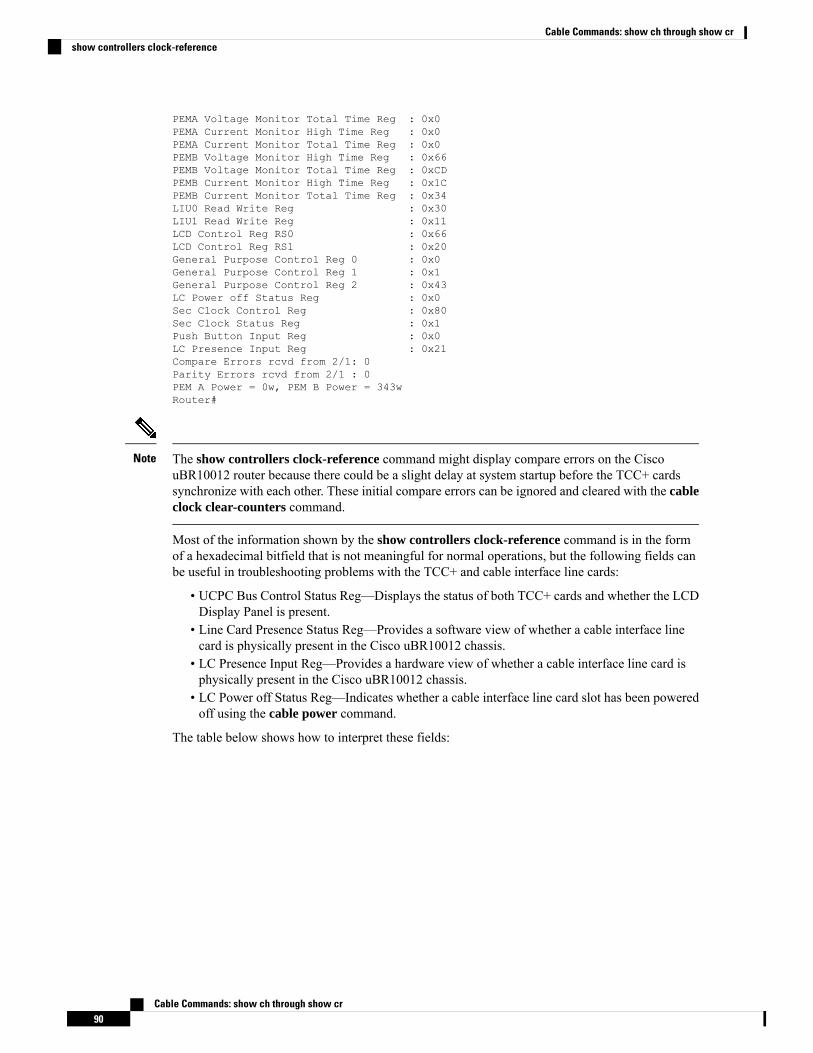
PEMA Voltage Monitor Total Time Reg : 0x0PEMA Current Monitor High Time Reg : 0x0PEMA Current Monitor Total Time Reg : 0x0PEMB Voltage Monitor High Time Reg : 0x66PEMB Voltage Monitor Total Time Reg : 0xCDPEMB Current Monitor High Time Reg : 0x1CPEMB Current Monitor Total Time Reg : 0x34LIU0 Read Write Reg : 0x30LIU1 Read Write Reg : 0x11LCD Control Reg RS0 : 0x66LCD Control Reg RS1 : 0x20General Purpose Control Reg 0 : 0x0General Purpose Control Reg 1 : 0x1General Purpose Control Reg 2 : 0x43LC Power off Status Reg : 0x0Sec Clock Control Reg : 0x80Sec Clock Status Reg : 0x1Push Button Input Reg : 0x0LC Presence Input Reg : 0x21Compare Errors rcvd from 2/1: 0Parity Errors rcvd from 2/1 : 0PEM A Power = 0w, PEM B Power = 343wRouter#
The show controllers clock-reference command might display compare errors on the CiscouBR10012 router because there could be a slight delay at system startup before the TCC+ cardssynchronize with each other. These initial compare errors can be ignored and cleared with the cableclock clear-counters command.
Note
Most of the information shown by the show controllers clock-reference command is in the formof a hexadecimal bitfield that is not meaningful for normal operations, but the following fields canbe useful in troubleshooting problems with the TCC+ and cable interface line cards:
• UCPC Bus Control Status Reg—Displays the status of both TCC+ cards and whether the LCDDisplay Panel is present.
• Line Card Presence Status Reg—Provides a software view of whether a cable interface linecard is physically present in the Cisco uBR10012 chassis.
• LC Presence Input Reg—Provides a hardware view of whether a cable interface line card isphysically present in the Cisco uBR10012 chassis.
• LC Power off Status Reg—Indicates whether a cable interface line card slot has been poweredoff using the cable power command.
The table below shows how to interpret these fields:
Cable Commands: show ch through show cr90
Cable Commands: show ch through show crshow controllers clock-reference
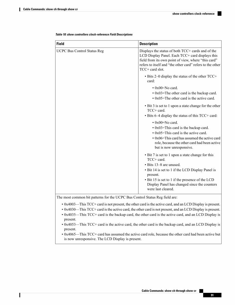
Table 10: show controllers clock-reference Field Descriptions
DescriptionField
Displays the status of both TCC+ cards and of theLCD Display Panel. Each TCC+ card displays thisfield from its own point of view, where “this card”refers to itself and “the other card” refers to the otherTCC+ card slot.
• Bits 2–0 display the status of the other TCC+card:
• 0x00=No card.• 0x03=The other card is the backup card.• 0x05=The other card is the active card.
• Bit 3 is set to 1 upon a state change for the otherTCC+ card.
• Bits 6–4 display the status of this TCC+ card:
• 0x00=No card.• 0x03=This card is the backup card.• 0x05=This card is the active card.• 0x06=This card has assumed the active cardrole, because the other card had been activebut is now unresponsive.
• Bit 7 is set to 1 upon a state change for thisTCC+ card.
• Bits 13–8 are unused.• Bit 14 is set to 1 if the LCD Display Panel ispresent.
• Bit 15 is set to 1 if the presence of the LCDDisplay Panel has changed since the counterswere last cleared.
UCPC Bus Control Status Reg
The most common bit patterns for the UCPC Bus Control Status Reg field are:
• 0x4003—This TCC+ card is not present, the other card is the active card, and an LCDDisplay is present.• 0x4030—This TCC+ card is the active card, the other card is not present, and an LCDDisplay is present.• 0x4035—This TCC+ card is the backup card, the other card is the active card, and an LCD Display ispresent.
• 0x4053—This TCC+ card is the active card, the other card is the backup card, and an LCD Display ispresent.
• 0x4065—This TCC+ card has assumed the active card role, because the other card had been active butis now unresponsive. The LCD Display is present.
Cable Commands: show ch through show cr91
Cable Commands: show ch through show crshow controllers clock-reference
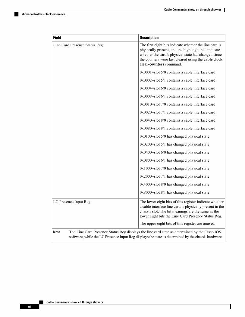
DescriptionField
The first eight bits indicate whether the line card isphysically present, and the high eight bits indicatewhether the card’s physical state has changed sincethe counters were last cleared using the cable clockclear-counters command.
0x0001=slot 5/0 contains a cable interface card
0x0002=slot 5/1 contains a cable interface card
0x0004=slot 6/0 contains a cable interface card
0x0008=slot 6/1 contains a cable interface card
0x0010=slot 7/0 contains a cable interface card
0x0020=slot 7/1 contains a cable interface card
0x0040=slot 8/0 contains a cable interface card
0x0080=slot 8/1 contains a cable interface card
0x0100=slot 5/0 has changed physical state
0x0200=slot 5/1 has changed physical state
0x0400=slot 6/0 has changed physical state
0x0800=slot 6/1 has changed physical state
0x1000=slot 7/0 has changed physical state
0x2000=slot 7/1 has changed physical state
0x4000=slot 8/0 has changed physical state
0x8000=slot 8/1 has changed physical state
Line Card Presence Status Reg
The lower eight bits of this register indicate whethera cable interface line card is physically present in thechassis slot. The bit meanings are the same as thelower eight bits the Line Card Presence Status Reg.
The upper eight bits of this register are unused.
LC Presence Input Reg
The Line Card Presence Status Reg displays the line card state as determined by the Cisco IOSsoftware, while the LC Presence Input Reg displays the state as determined by the chassis hardware.
Note
Cable Commands: show ch through show cr92
Cable Commands: show ch through show crshow controllers clock-reference
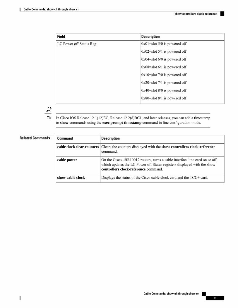
DescriptionField
0x01=slot 5/0 is powered off
0x02=slot 5/1 is powered off
0x04=slot 6/0 is powered off
0x08=slot 6/1 is powered off
0x10=slot 7/0 is powered off
0x20=slot 7/1 is powered off
0x40=slot 8/0 is powered off
0x80=slot 8/1 is powered off
LC Power off Status Reg
In Cisco IOS Release 12.1(12)EC, Release 12.2(8)BC1, and later releases, you can add a timestampto show commands using the exec prompt timestamp command in line configuration mode.
Tip
Related Commands DescriptionCommand
Clears the counters displayed with the show controllers clock-referencecommand.
cable clock clear-counters
On the Cisco uBR10012 routers, turns a cable interface line card on or off,which updates the LC Power off Status registers displayed with the showcontrollers clock-reference command.
cable power
Displays the status of the Cisco cable clock card and the TCC+ card.show cable clock
Cable Commands: show ch through show cr93
Cable Commands: show ch through show crshow controllers clock-reference
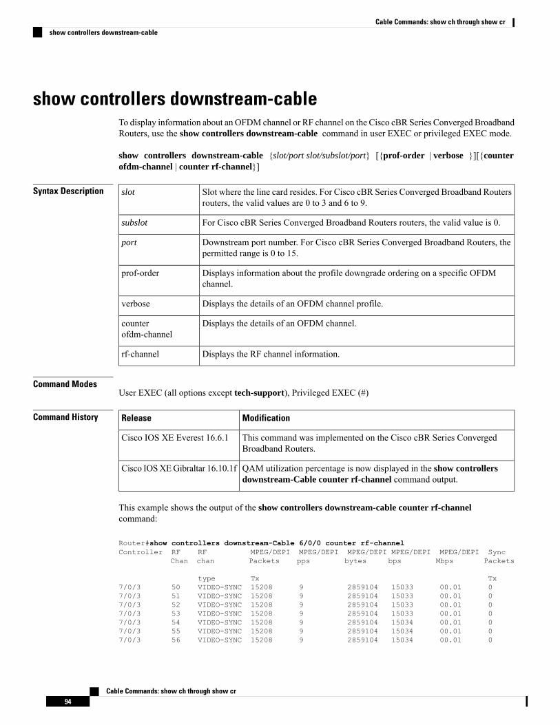
show controllers downstream-cableTo display information about an OFDM channel or RF channel on the Cisco cBR Series Converged BroadbandRouters, use the show controllers downstream-cable command in user EXEC or privileged EXEC mode.
show controllers downstream-cable {slot/port slot/subslot/port} [{prof-order | verbose }][{counterofdm-channel | counter rf-channel}]
Syntax Description Slot where the line card resides. For Cisco cBR Series Converged Broadband Routersrouters, the valid values are 0 to 3 and 6 to 9.
slot
For Cisco cBR Series Converged Broadband Routers routers, the valid value is 0.subslot
Downstream port number. For Cisco cBR Series Converged Broadband Routers, thepermitted range is 0 to 15.
port
Displays information about the profile downgrade ordering on a specific OFDMchannel.
prof-order
Displays the details of an OFDM channel profile.verbose
Displays the details of an OFDM channel.counterofdm-channel
Displays the RF channel information.rf-channel
Command ModesUser EXEC (all options except tech-support), Privileged EXEC (#)
Command History ModificationRelease
This command was implemented on the Cisco cBR Series ConvergedBroadband Routers.
Cisco IOS XE Everest 16.6.1
QAM utilization percentage is now displayed in the show controllersdownstream-Cable counter rf-channel command output.
Cisco IOSXEGibraltar 16.10.1f
This example shows the output of the show controllers downstream-cable counter rf-channelcommand:
Router#show controllers downstream-Cable 6/0/0 counter rf-channelController RF RF MPEG/DEPI MPEG/DEPI MPEG/DEPI MPEG/DEPI MPEG/DEPI Sync
Chan chan Packets pps bytes bps Mbps Packets
type Tx Tx7/0/3 50 VIDEO-SYNC 15208 9 2859104 15033 00.01 07/0/3 51 VIDEO-SYNC 15208 9 2859104 15033 00.01 07/0/3 52 VIDEO-SYNC 15208 9 2859104 15033 00.01 07/0/3 53 VIDEO-SYNC 15208 9 2859104 15033 00.01 07/0/3 54 VIDEO-SYNC 15208 9 2859104 15034 00.01 07/0/3 55 VIDEO-SYNC 15208 9 2859104 15034 00.01 07/0/3 56 VIDEO-SYNC 15208 9 2859104 15034 00.01 0
Cable Commands: show ch through show cr94
Cable Commands: show ch through show crshow controllers downstream-cable
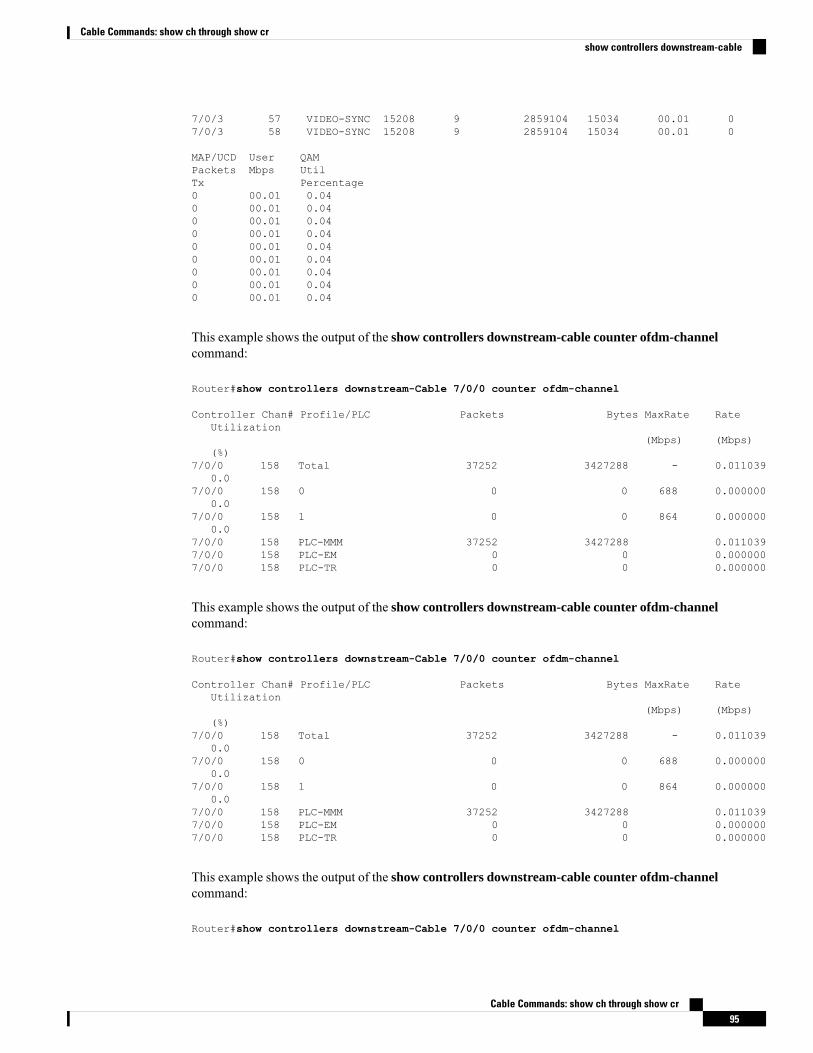
7/0/3 57 VIDEO-SYNC 15208 9 2859104 15034 00.01 07/0/3 58 VIDEO-SYNC 15208 9 2859104 15034 00.01 0
MAP/UCD User QAMPackets Mbps UtilTx Percentage0 00.01 0.040 00.01 0.040 00.01 0.040 00.01 0.040 00.01 0.040 00.01 0.040 00.01 0.040 00.01 0.040 00.01 0.04
This example shows the output of the show controllers downstream-cable counter ofdm-channelcommand:
Router#show controllers downstream-Cable 7/0/0 counter ofdm-channel
Controller Chan# Profile/PLC Packets Bytes MaxRate RateUtilization
(Mbps) (Mbps)(%)
7/0/0 158 Total 37252 3427288 - 0.0110390.0
7/0/0 158 0 0 0 688 0.0000000.0
7/0/0 158 1 0 0 864 0.0000000.0
7/0/0 158 PLC-MMM 37252 3427288 0.0110397/0/0 158 PLC-EM 0 0 0.0000007/0/0 158 PLC-TR 0 0 0.000000
This example shows the output of the show controllers downstream-cable counter ofdm-channelcommand:
Router#show controllers downstream-Cable 7/0/0 counter ofdm-channel
Cable Commands: show ch through show cr95
Cable Commands: show ch through show crshow controllers downstream-cable
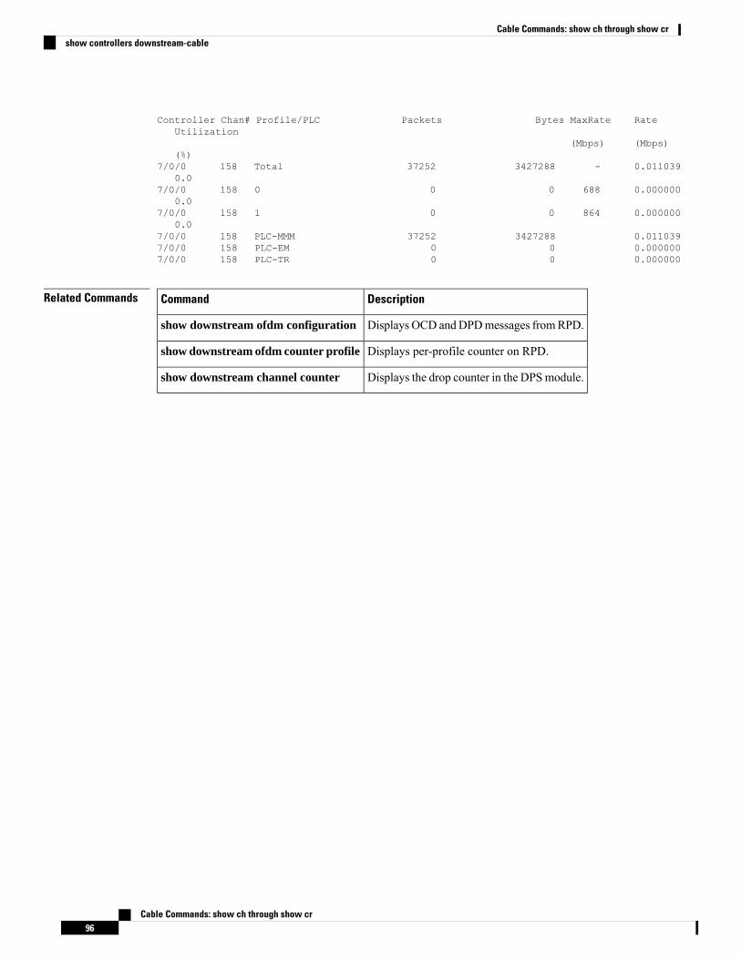
Controller Chan# Profile/PLC Packets Bytes MaxRate RateUtilization
(Mbps) (Mbps)(%)
7/0/0 158 Total 37252 3427288 - 0.0110390.0
7/0/0 158 0 0 0 688 0.0000000.0
7/0/0 158 1 0 0 864 0.0000000.0
7/0/0 158 PLC-MMM 37252 3427288 0.0110397/0/0 158 PLC-EM 0 0 0.0000007/0/0 158 PLC-TR 0 0 0.000000
Related Commands DescriptionCommand
Displays OCD andDPDmessages fromRPD.show downstream ofdm configuration
Displays per-profile counter on RPD.show downstream ofdm counter profile
Displays the drop counter in the DPSmodule.show downstream channel counter
Cable Commands: show ch through show cr96
Cable Commands: show ch through show crshow controllers downstream-cable
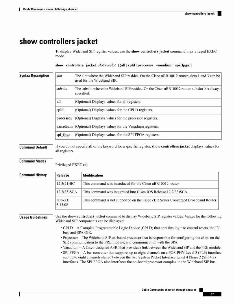
show controllers jacketTo display Wideband SIP register values, use the show controllers jacket command in privileged EXECmode.
show controllers jacket slot/subslot [{all | cpld | processor | vanadium | spi_fpga}]
Syntax Description The slot where the Wideband SIP resides. On the Cisco uBR10012 router, slots 1 and 3 can beused for the Wideband SIP.
slot
The subslot where theWideband SIP resides. On the Cisco uBR10012 router, subslot 0 is alwaysspecified.
subslot
(Optional) Displays values for all registers.all
(Optional) Displays values for the CPLD registers.cpld
(Optional) Displays values for the processor registers.processor
(Optional) Displays values for the Vanadium registers.vanadium
(Optional) Displays values for the SPI FPGA registers.spi_fpga
Command Default If you do not specify all or the keyword for a specific register, show controllers jacket displays values forall registers.
Command ModesPrivileged EXEC (#)
Command History ModificationRelease
This command was introduced for the Cisco uBR10012 router.12.3(21)BC
This command was integrated into Cisco IOS Release 12.2(33)SCA.12.2(33)SCA
This command is not supported on the Cisco cBR Series Converged Broadband Router.IOS-XE3.15.0S
Usage Guidelines Use the show controllers jacket command to display Wideband SIP register values. Values for the followingWideband SIP components can be displayed:
• CPLD—A Complex Programmable Logic Device (CPLD) that contains logic to control resets, the I/Obus, and SPA OIR.
• Processor—The Wideband SIP on-board processor that is responsible for configuring the chips on theSIP, communication to the PRE module, and communication with the SPA.
• Vanadium—ACisco-designed ASIC that provides a link between theWideband SIP and the PREmodule.• SPI FPGA—A bus converter that supports up to eight channels on a POS-PHY Level 3 (PL3) interfaceand up to eight channels shared between the two System Packet Interface Level 4 Phase 2 (SPI 4.2)interfaces. The SPI FPGA also interfaces the on-board processor complex to the Wideband SIP bus.
Cable Commands: show ch through show cr97
Cable Commands: show ch through show crshow controllers jacket
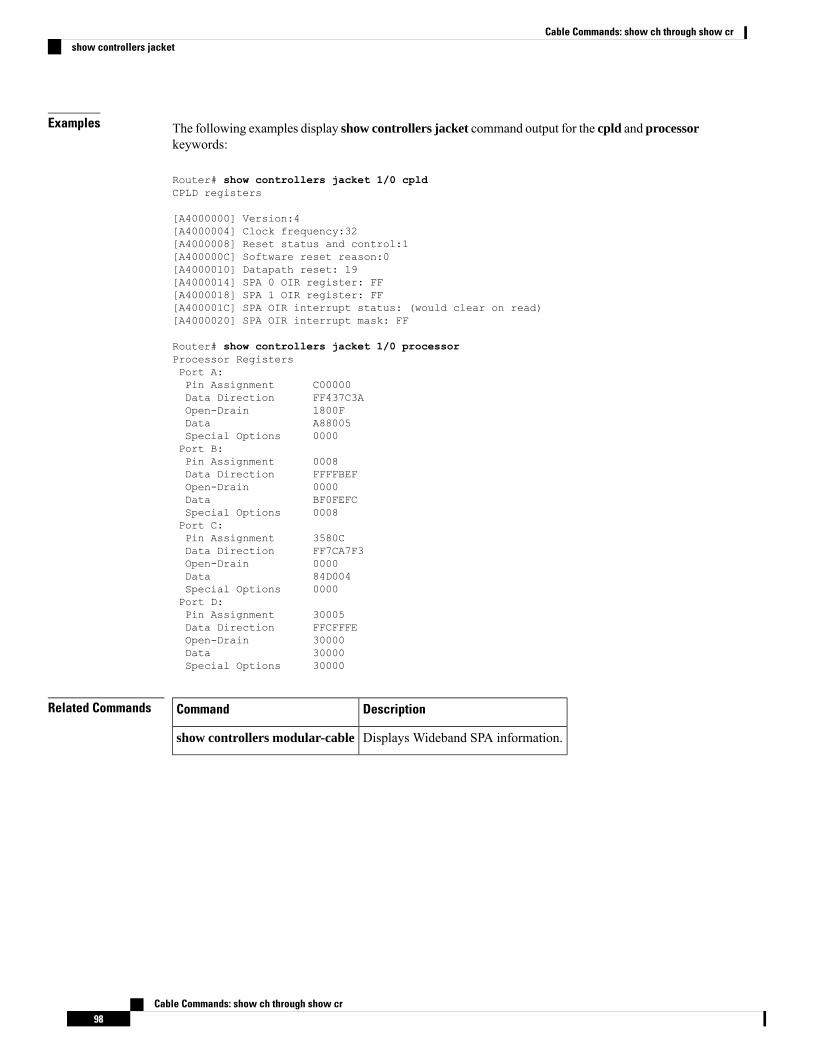
Examples The following examples display show controllers jacket command output for the cpld and processorkeywords:
Router# show controllers jacket 1/0 cpldCPLD registers
[A4000000] Version:4[A4000004] Clock frequency:32[A4000008] Reset status and control:1[A400000C] Software reset reason:0[A4000010] Datapath reset: 19[A4000014] SPA 0 OIR register: FF[A4000018] SPA 1 OIR register: FF[A400001C] SPA OIR interrupt status: (would clear on read)[A4000020] SPA OIR interrupt mask: FF
Router# show controllers jacket 1/0 processorProcessor RegistersPort A:Pin Assignment C00000Data Direction FF437C3AOpen-Drain 1800FData A88005Special Options 0000Port B:Pin Assignment 0008Data Direction FFFFBEFOpen-Drain 0000Data BF0FEFCSpecial Options 0008Port C:Pin Assignment 3580CData Direction FF7CA7F3Open-Drain 0000Data 84D004Special Options 0000Port D:Pin Assignment 30005Data Direction FFCFFFEOpen-Drain 30000Data 30000Special Options 30000
Related Commands DescriptionCommand
Displays Wideband SPA information.show controllers modular-cable
Cable Commands: show ch through show cr98
Cable Commands: show ch through show crshow controllers jacket
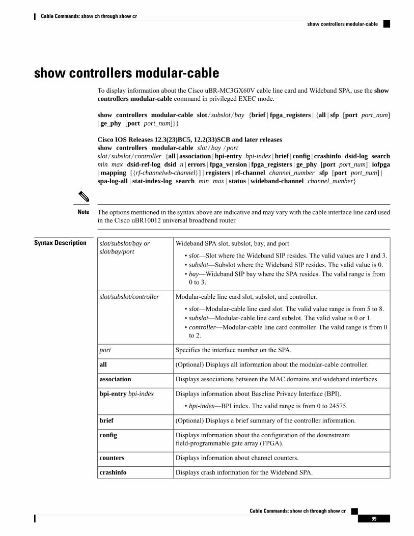
show controllers modular-cableTo display information about the Cisco uBR-MC3GX60V cable line card and Wideband SPA, use the showcontrollers modular-cable command in privileged EXEC mode.
show controllers modular-cable slot/subslot/bay {brief | fpga_registers | {all | sfp [port port_num]| ge_phy [port port_num]}}
Cisco IOS Releases 12.3(23)BC5, 12.2(33)SCB and later releasesshow controllers modular-cable slot/bay /portslot/subslot/controller {all | association | bpi-entry bpi-index | brief | config | crashinfo | dsid-log searchmin max | dsid-ref-log dsid n | errors | fpga_version | fpga_registers | ge_phy [port port_num] | iofpga| mapping [{rf-channelwb-channel}] | registers | rf-channel channel_number | sfp [port port_num] |spa-log-all | stat-index-log search min max | status | wideband-channel channel_number}
The options mentioned in the syntax above are indicative and may vary with the cable interface line card usedin the Cisco uBR10012 universal broadband router.
Note
Syntax Description Wideband SPA slot, subslot, bay, and port.
• slot—Slot where the Wideband SIP resides. The valid values are 1 and 3.• subslot—Subslot where the Wideband SIP resides. The valid value is 0.• bay—Wideband SIP bay where the SPA resides. The valid range is from0 to 3.
slot/subslot/bay orslot/bay/port
Modular-cable line card slot, subslot, and controller.
• slot—Modular-cable line card slot. The valid value range is from 5 to 8.• subslot—Modular-cable line card subslot. The valid value is 0 or 1.• controller—Modular-cable line card controller. The valid range is from 0to 2.
slot/subslot/controller
Specifies the interface number on the SPA.port
(Optional) Displays all information about the modular-cable controller.all
Displays associations between the MAC domains and wideband interfaces.association
Displays information about Baseline Privacy Interface (BPI).
• bpi-index—BPI index. The valid range is from 0 to 24575.
bpi-entry bpi-index
(Optional) Displays a brief summary of the controller information.brief
Displays information about the configuration of the downstreamfield-programmable gate array (FPGA).
config
Displays information about channel counters.counters
Displays crash information for the Wideband SPA.crashinfo
Cable Commands: show ch through show cr99
Cable Commands: show ch through show crshow controllers modular-cable
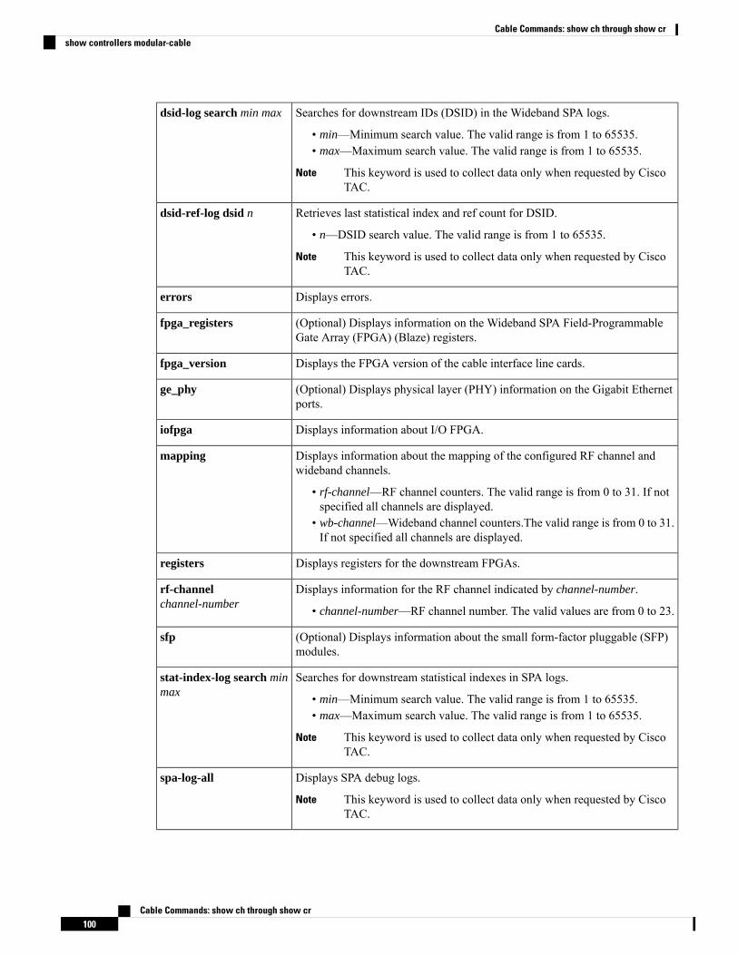
Searches for downstream IDs (DSID) in the Wideband SPA logs.
• min—Minimum search value. The valid range is from 1 to 65535.• max—Maximum search value. The valid range is from 1 to 65535.
This keyword is used to collect data only when requested by CiscoTAC.
Note
dsid-log search min max
Retrieves last statistical index and ref count for DSID.
• n—DSID search value. The valid range is from 1 to 65535.
This keyword is used to collect data only when requested by CiscoTAC.
Note
dsid-ref-log dsid n
Displays errors.errors
(Optional) Displays information on the Wideband SPA Field-ProgrammableGate Array (FPGA) (Blaze) registers.
fpga_registers
Displays the FPGA version of the cable interface line cards.fpga_version
(Optional) Displays physical layer (PHY) information on the Gigabit Ethernetports.
ge_phy
Displays information about I/O FPGA.iofpga
Displays information about the mapping of the configured RF channel andwideband channels.
• rf-channel—RF channel counters. The valid range is from 0 to 31. If notspecified all channels are displayed.
• wb-channel—Wideband channel counters.The valid range is from 0 to 31.If not specified all channels are displayed.
mapping
Displays registers for the downstream FPGAs.registers
Displays information for the RF channel indicated by channel-number.
• channel-number—RF channel number. The valid values are from 0 to 23.
rf-channelchannel-number
(Optional) Displays information about the small form-factor pluggable (SFP)modules.
sfp
Searches for downstream statistical indexes in SPA logs.
• min—Minimum search value. The valid range is from 1 to 65535.• max—Maximum search value. The valid range is from 1 to 65535.
This keyword is used to collect data only when requested by CiscoTAC.
Note
stat-index-log search minmax
Displays SPA debug logs.
This keyword is used to collect data only when requested by CiscoTAC.
Note
spa-log-all
Cable Commands: show ch through show cr100
Cable Commands: show ch through show crshow controllers modular-cable
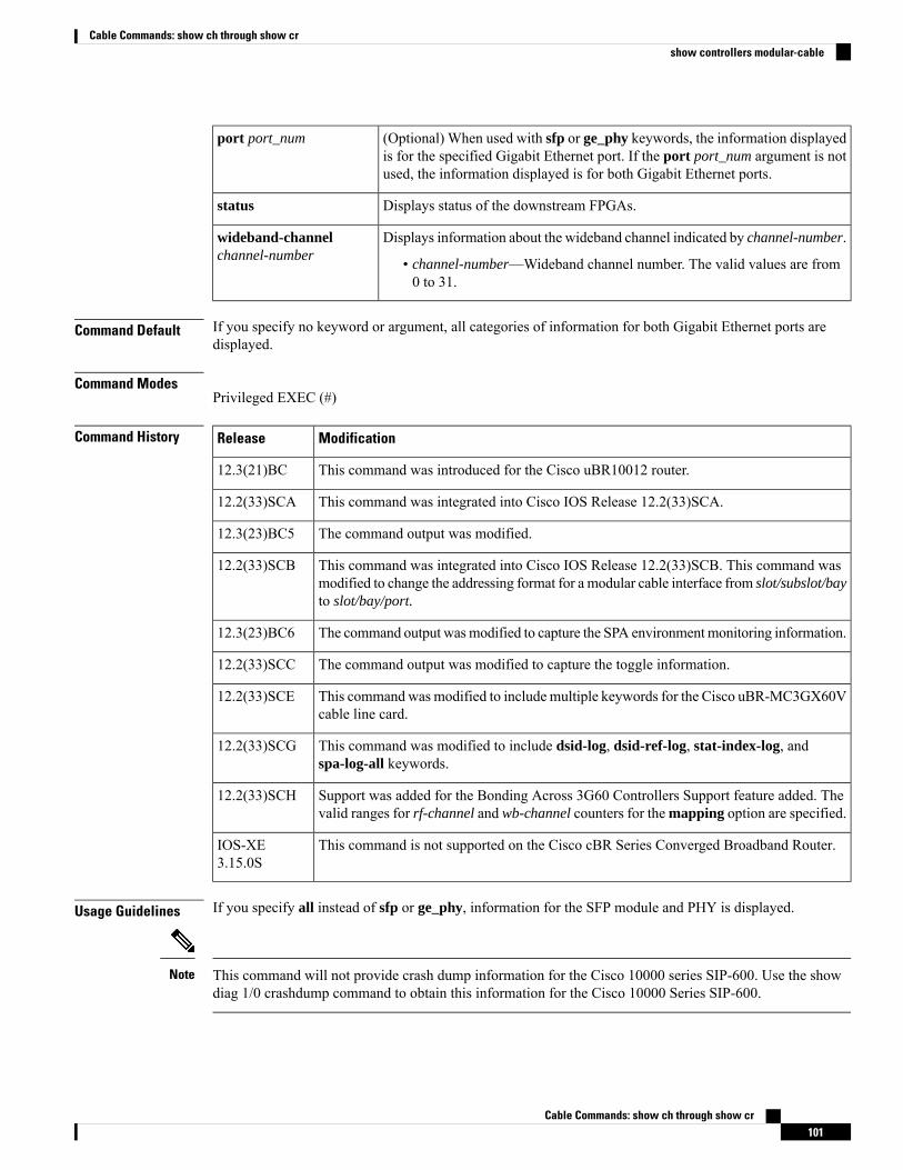
(Optional) When used with sfp or ge_phy keywords, the information displayedis for the specified Gigabit Ethernet port. If the port port_num argument is notused, the information displayed is for both Gigabit Ethernet ports.
port port_num
Displays status of the downstream FPGAs.status
Displays information about the wideband channel indicated by channel-number.
• channel-number—Wideband channel number. The valid values are from0 to 31.
wideband-channelchannel-number
Command Default If you specify no keyword or argument, all categories of information for both Gigabit Ethernet ports aredisplayed.
Command ModesPrivileged EXEC (#)
Command History ModificationRelease
This command was introduced for the Cisco uBR10012 router.12.3(21)BC
This command was integrated into Cisco IOS Release 12.2(33)SCA.12.2(33)SCA
The command output was modified.12.3(23)BC5
This command was integrated into Cisco IOS Release 12.2(33)SCB. This command wasmodified to change the addressing format for a modular cable interface from slot/subslot/bayto slot/bay/port.
12.2(33)SCB
The command output wasmodified to capture the SPA environmentmonitoring information.12.3(23)BC6
The command output was modified to capture the toggle information.12.2(33)SCC
This commandwas modified to includemultiple keywords for the Cisco uBR-MC3GX60Vcable line card.
12.2(33)SCE
This command was modified to include dsid-log, dsid-ref-log, stat-index-log, andspa-log-all keywords.
12.2(33)SCG
Support was added for the Bonding Across 3G60 Controllers Support feature added. Thevalid ranges for rf-channel and wb-channel counters for the mapping option are specified.
12.2(33)SCH
This command is not supported on the Cisco cBR Series Converged Broadband Router.IOS-XE3.15.0S
Usage Guidelines If you specify all instead of sfp or ge_phy, information for the SFP module and PHY is displayed.
This command will not provide crash dump information for the Cisco 10000 series SIP-600. Use the showdiag 1/0 crashdump command to obtain this information for the Cisco 10000 Series SIP-600.
Note
Cable Commands: show ch through show cr101
Cable Commands: show ch through show crshow controllers modular-cable
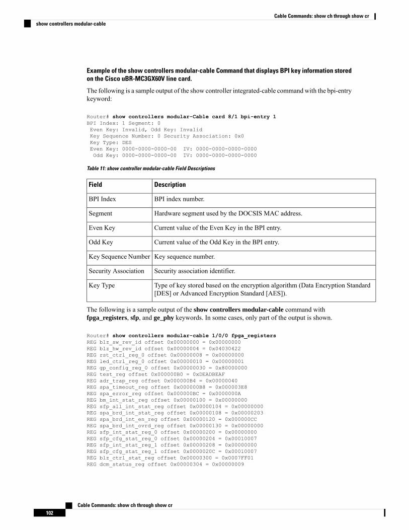
Example of the show controllers modular-cable Command that displays BPI key information storedon the Cisco uBR-MC3GX60V line card.
The following is a sample output of the show controller integrated-cable commandwith the bpi-entrykeyword:
Router# show controllers modular-Cable card 8/1 bpi-entry 1BPI Index: 1 Segment: 0Even Key: Invalid, Odd Key: InvalidKey Sequence Number: 0 Security Association: 0x0Key Type: DESEven Key: 0000-0000-0000-00 IV: 0000-0000-0000-0000Odd Key: 0000-0000-0000-00 IV: 0000-0000-0000-0000
Table 11: show controller modular-cable Field Descriptions
DescriptionField
BPI index number.BPI Index
Hardware segment used by the DOCSIS MAC address.Segment
Current value of the Even Key in the BPI entry.Even Key
Current value of the Odd Key in the BPI entry.Odd Key
Key sequence number.Key Sequence Number
Security association identifier.Security Association
Type of key stored based on the encryption algorithm (Data Encryption Standard[DES] or Advanced Encryption Standard [AES]).
Key Type
The following is a sample output of the show controllers modular-cable command withfpga_registers, sfp, and ge_phy keywords. In some cases, only part of the output is shown.
Router# show controllers modular-cable 1/0/0 fpga_registersREG blz_sw_rev_id offset 0x00000000 = 0x00000000REG blz_hw_rev_id offset 0x00000004 = 0x04030422REG rst_ctrl_reg_0 offset 0x00000008 = 0x00000000REG led_ctrl_reg_0 offset 0x00000010 = 0x00000001REG gp_config_reg_0 offset 0x00000030 = 0x80000000REG test_reg offset 0x000000B0 = 0xDEADBEAFREG adr_trap_reg offset 0x000000B4 = 0x00000040REG spa_timeout_reg offset 0x000000B8 = 0x000003E8REG spa_error_reg offset 0x000000BC = 0x0000000AREG bm_int_stat_reg offset 0x00000100 = 0x00000000REG sfp_all_int_stat_reg offset 0x00000104 = 0x00000000REG spa_brd_int_stat_reg offset 0x00000108 = 0x00000203REG spa_brd_int_en_reg offset 0x00000120 = 0x000000CCREG spa_brd_int_ovrd_reg offset 0x00000130 = 0x00000000REG sfp_int_stat_reg_0 offset 0x00000200 = 0x00000000REG sfp_cfg_stat_reg_0 offset 0x00000204 = 0x00010007REG sfp_int_stat_reg_1 offset 0x00000208 = 0x00000000REG sfp_cfg_stat_reg_1 offset 0x0000020C = 0x00010007REG blz_ctrl_stat_reg offset 0x00000300 = 0x0007FF01REG dcm_status_reg offset 0x00000304 = 0x00000009
Cable Commands: show ch through show cr102
Cable Commands: show ch through show crshow controllers modular-cable
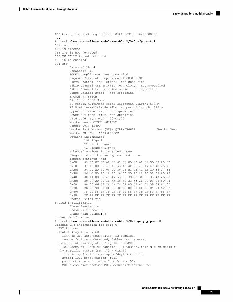
REG blz_sp_int_stat_reg_0 offset 0x00000310 = 0x00000008...Router# show controllers modular-cable 1/0/0 sfp port 1SFP in port 1SFP is presentSFP LOS is not detectedSFP TX FAULT is not detectedSFP TX is enabledID: SFP
Extended ID: 4Connector: LCSONET compliance: not specifiedGigabit Ethernet compliance: 1000BASE-SXFibre Channel link length: not specifiedFibre Channel transmitter technology: not specifiedFibre Channel transmission media: not specifiedFibre Channel speed: not specifiedEncoding: 8B10BBit Rate: 1300 Mbps50 micron-multimode fiber supported length: 550 m62.5 micron-multimode fiber supported length: 270 mUpper bit rate limit: not specifiedLower bit rate limit: not specifiedDate code (yy/mm/dd): 05/02/23Vendor name: CISCO-AGILENTVendor OUI: 12499Vendor Part Number (PN): QFBR-5766LP Vendor Rev:Vendor SN (SN): AGS090855CEOptions implemented:
LOS SignalTX Fault SignalTX Disable Signal
Enhanced options implemented: noneDiagnostic monitoring implemented: noneIdprom contents (hex):0x00: 03 04 07 00 00 00 01 00 00 00 00 01 0D 00 00 000x10: 37 1B 00 00 43 49 53 43 4F 2D 41 47 49 4C 45 4E0x20: 54 20 20 20 00 00 30 D3 51 46 42 52 2D 35 37 360x30: 36 4C 50 20 20 20 20 20 20 20 20 20 03 52 00 B50x40: 00 1A 00 00 41 47 53 30 39 30 38 35 35 43 45 200x50: 20 20 20 20 30 35 30 32 32 33 20 20 00 00 00 C40x60: 00 00 06 C9 F0 FA 7C 01 B3 C8 41 6B 39 04 FC 850x70: BB 20 9E 00 00 00 00 00 00 00 00 00 B4 94 52 CC0x80: FF FF FF FF FF FF FF FF FF FF FF FF FF FF FF FF0x90: FF FF FF FF FF FF FF FF FF FF FF FF FF FF FF FFState: Initalized
Phased InitializationPhase Reached: 4Phase Exit Code: 0Phase Read Offset: 0
Socket VerificationRouter# show controllers modular-cable 1/0/0 ge_phy port 0Gigabit PHY information for port 0:PHY Status:status (reg 1) = 0x16Dlink is up, auto-negotiation is completeremote fault not detected, jabber not detected
Extended status register (reg 15) = 0xC0001000BaseX full duplex capable 1000BaseX half duplex capable
phy specific status (reg 17) = 0xAC14link is up (real-time), speed/duplex resolvedspeed: 1000 Mbps, duplex: fullpage not received, cable length is < 50mMDI cross-over status: MDI, downshift status: no
Cable Commands: show ch through show cr103
Cable Commands: show ch through show crshow controllers modular-cable
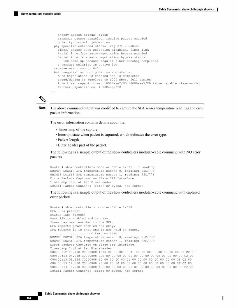
energy detect status: sleeptransmit pause: disabled, receive pause: enabledpolarity: normal, jabber: no
phy specific extended status (reg 27) = 0xB487Fiber/ copper auto selection disabled, fiber linkSerial interface auto-negotiation bypass enabledSerial interface auto-negotiation bypass status:Link came up because regular fiber autoneg completed
Interrupt polarity is active lowreceive error count: 0x0Auto-negotiation configuration and status:Auto-negotiation is enabled and is completedSpeed/duplex is resolved to 1000 Mbps, full duplexAdvertised capabilities: 1000BaseX/HD 1000BaseX/FD Pause capable (Asymmetric)Partner capabilities: 1000BaseX/FD
...
The above command output was modified to capture the SPA sensor temperature readings and errorpacket information.
Note
The error information contains details about the:
• Timestamp of the capture.• Interrupt state when packet is captured, which indicates the error type.• Packet length.• Blaze header part of the packet.
The following is a sample output of the show controllers modular-cable command with NO errorpackets.
Router# show controllers modular-Cable 1/0/1 | b readingWBCMTS DOCSIS SPA temperature sensor 0, reading: 25C/77FWBCMTS DOCSIS SPA temperature sensor 1, reading: 25C/77FError Packets Captured on Blaze SPI Interface:Timestamp IntStat Len BlazeHeaderDetail Packet Content: (first 80 bytes, hex format)
The following is a sample output of the show controllers modular-cable command with capturederror packets.
Router# show controllers modular-Cable 1/0/0SPA 0 is presentstatus LED: [green]Host 12V is enabled and is okay.Power has been enabled to the SPA.SPA reports power enabled and okay.SPA reports it is okay and is NOT held in reset.................... <<< text omittedWBCMTS DOCSIS SPA temperature sensor 0, reading: 26C/78FWBCMTS DOCSIS SPA temperature sensor 1, reading: 25C/77FError Packets Captured on Blaze SPI Interface:Timestamp IntStat Len BlazeHeader000:00:12:49.190 C0000808 1510 00 00 00 00 01 00 00 00 00 00 00 00 00 0F C2 00000:00:13:04.948 C0000808 796 00 00 00 00 01 00 00 00 00 00 00 00 00 0F C2 00000:00:13:09.468 C0000808 60 00 00 00 00 01 00 00 00 00 00 00 00 00 0F C2 00000:00:13:14.320 C0000808 26 00 00 00 00 01 00 00 00 00 00 00 00 00 0F C2 00000:00:13:18.088 C0000808 496 00 00 00 00 01 00 00 00 00 00 00 00 00 0F C2 00Detail Packet Content: (first 80 bytes, hex format)
Cable Commands: show ch through show cr104
Cable Commands: show ch through show crshow controllers modular-cable
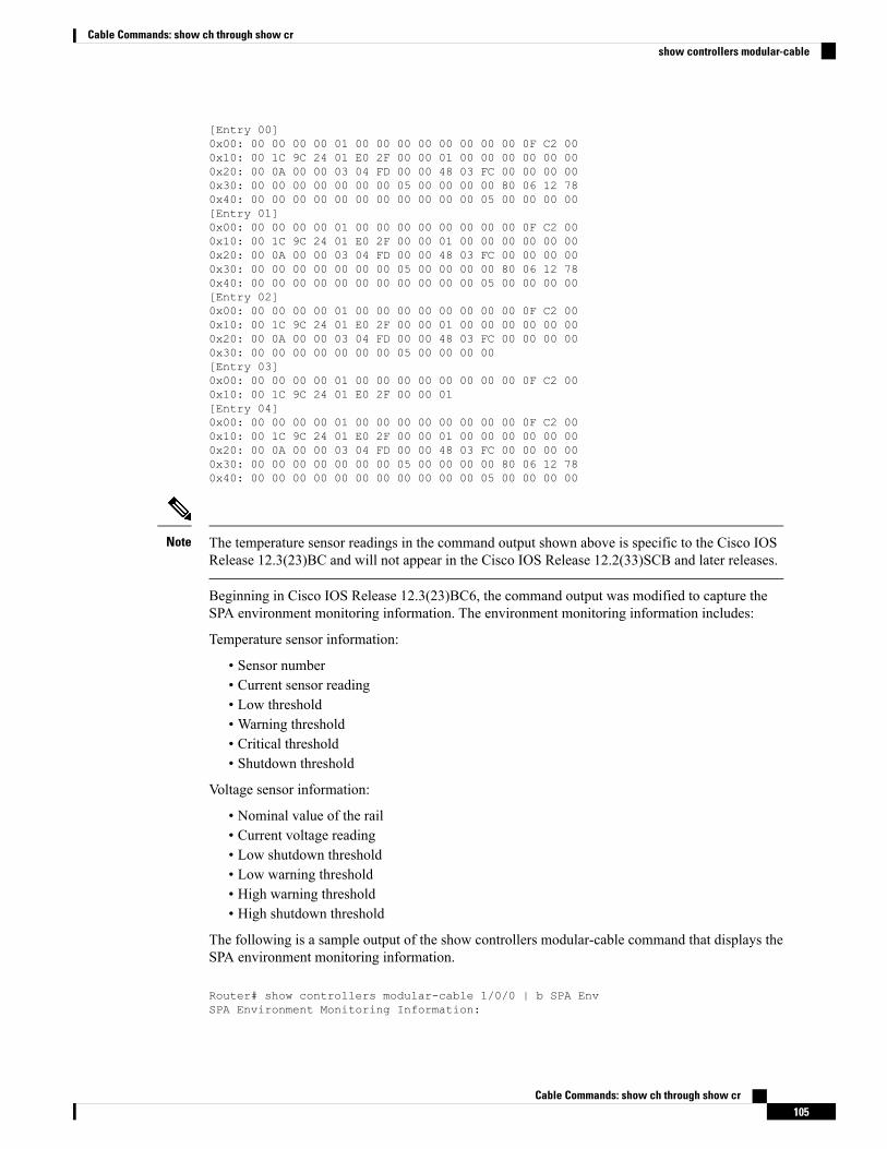
[Entry 00]0x00: 00 00 00 00 01 00 00 00 00 00 00 00 00 0F C2 000x10: 00 1C 9C 24 01 E0 2F 00 00 01 00 00 00 00 00 000x20: 00 0A 00 00 03 04 FD 00 00 48 03 FC 00 00 00 000x30: 00 00 00 00 00 00 00 05 00 00 00 00 80 06 12 780x40: 00 00 00 00 00 00 00 00 00 00 00 05 00 00 00 00[Entry 01]0x00: 00 00 00 00 01 00 00 00 00 00 00 00 00 0F C2 000x10: 00 1C 9C 24 01 E0 2F 00 00 01 00 00 00 00 00 000x20: 00 0A 00 00 03 04 FD 00 00 48 03 FC 00 00 00 000x30: 00 00 00 00 00 00 00 05 00 00 00 00 80 06 12 780x40: 00 00 00 00 00 00 00 00 00 00 00 05 00 00 00 00[Entry 02]0x00: 00 00 00 00 01 00 00 00 00 00 00 00 00 0F C2 000x10: 00 1C 9C 24 01 E0 2F 00 00 01 00 00 00 00 00 000x20: 00 0A 00 00 03 04 FD 00 00 48 03 FC 00 00 00 000x30: 00 00 00 00 00 00 00 05 00 00 00 00[Entry 03]0x00: 00 00 00 00 01 00 00 00 00 00 00 00 00 0F C2 000x10: 00 1C 9C 24 01 E0 2F 00 00 01[Entry 04]0x00: 00 00 00 00 01 00 00 00 00 00 00 00 00 0F C2 000x10: 00 1C 9C 24 01 E0 2F 00 00 01 00 00 00 00 00 000x20: 00 0A 00 00 03 04 FD 00 00 48 03 FC 00 00 00 000x30: 00 00 00 00 00 00 00 05 00 00 00 00 80 06 12 780x40: 00 00 00 00 00 00 00 00 00 00 00 05 00 00 00 00
The temperature sensor readings in the command output shown above is specific to the Cisco IOSRelease 12.3(23)BC and will not appear in the Cisco IOS Release 12.2(33)SCB and later releases.
Note
Beginning in Cisco IOS Release 12.3(23)BC6, the command output was modified to capture theSPA environment monitoring information. The environment monitoring information includes:
Temperature sensor information:
• Sensor number• Current sensor reading• Low threshold• Warning threshold• Critical threshold• Shutdown threshold
Voltage sensor information:
• Nominal value of the rail• Current voltage reading• Low shutdown threshold• Low warning threshold• High warning threshold• High shutdown threshold
The following is a sample output of the show controllers modular-cable command that displays theSPA environment monitoring information.
Router# show controllers modular-cable 1/0/0 | b SPA EnvSPA Environment Monitoring Information:
Cable Commands: show ch through show cr105
Cable Commands: show ch through show crshow controllers modular-cable
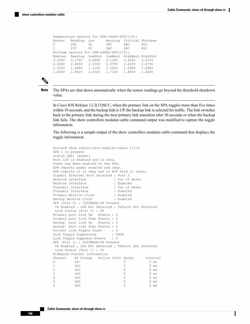
Temperature sensors for SPA-24XDS-SFP[1/0]:Sensor Reading Low Warning Critical Shutdown0 26C 0C 58C 68C 85C1 27C 0C 58C 68C 85CVoltage sensors for SPA-24XDS-SFP[1/0]:Nominal Reading LowShut LowWarn HighWarn HighShut3.300V 3.276V 3.069V 3.135V 3.465V 3.531V2.500V 2.485V 2.325V 2.375V 2.625V 2.675V1.200V 1.186V 1.116V 1.140V 1.260V 1.284V1.800V 1.801V 1.674V 1.710V 1.890V 1.926V
The SPAs are shut down automatically when the sensor readings go beyond the threshold shutdownvalue.
Note
In Cisco IOS Release 12.2(33)SCC, when the primary link on the SPA toggles more than five timeswithin 30 seconds, and the backup link is UP, the backup link is selected for traffic. The link switchesback to the primary link during the next primary link transition after 30 seconds or when the backuplink fails. The show controllers modular-cable command output was modified to capture the toggleinformation.
The following is a sample output of the show controllers modular-cable command that displays thetoggle information.
Router# show controllers modular-cable 1/1/0SPA 1 is presentstatus LED: [green]Host 12V is enabled and is okay.Power has been enabled to the SPA.SPA reports power enabled and okay.SPA reports it is okay and is NOT held in reset.Gigabit Ethernet Port Selected : Port 0Receive Interface : Out of ResetReceive Interface : EnabledTransmit Interface : Out of ResetTransmit Interface : EnabledPrimary Receive Clock : EnabledBackup Receive Clock : EnabledSFP [Port 0] : 1000BASE-SX PresentTx Enabled , LOS Not Detected , TxFault Not DetectedLink Status [Port 0] : UPPrimary port Link Up Events : 2Primary port Link Down Events : 0Backup port Link Up Events : 2Backup port Link Down Events : 0Current Link Toggle Count : 0Link Toggle Suppressed : TRUELink Toggle Suppress Events : 0SFP [Port 1] : 1000BASE-SX PresentTx Enabled , LOS Not Detected , TxFault Not DetectedLink Status [Port 1] : UPWideband Channel informationChannel RF bitmap Police Info: Bytes Interval0 0x7 0 0 ms1 0xC 0 0 ms2 0x0 0 0 ms3 0x0 0 0 ms4 0x0 0 0 ms5 0x0 0 0 ms6 0x0 0 0 ms
Cable Commands: show ch through show cr106
Cable Commands: show ch through show crshow controllers modular-cable
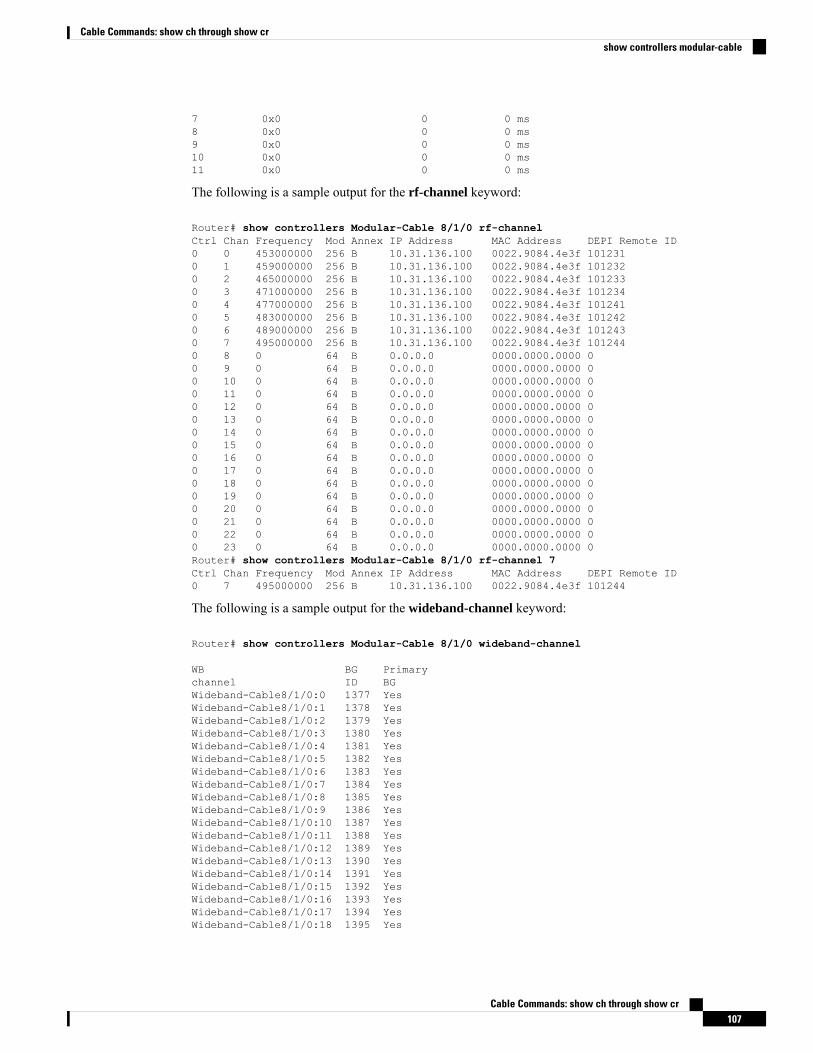
7 0x0 0 0 ms8 0x0 0 0 ms9 0x0 0 0 ms10 0x0 0 0 ms11 0x0 0 0 ms
The following is a sample output for the rf-channel keyword:
Router# show controllers Modular-Cable 8/1/0 rf-channelCtrl Chan Frequency Mod Annex IP Address MAC Address DEPI Remote ID0 0 453000000 256 B 10.31.136.100 0022.9084.4e3f 1012310 1 459000000 256 B 10.31.136.100 0022.9084.4e3f 1012320 2 465000000 256 B 10.31.136.100 0022.9084.4e3f 1012330 3 471000000 256 B 10.31.136.100 0022.9084.4e3f 1012340 4 477000000 256 B 10.31.136.100 0022.9084.4e3f 1012410 5 483000000 256 B 10.31.136.100 0022.9084.4e3f 1012420 6 489000000 256 B 10.31.136.100 0022.9084.4e3f 1012430 7 495000000 256 B 10.31.136.100 0022.9084.4e3f 1012440 8 0 64 B 0.0.0.0 0000.0000.0000 00 9 0 64 B 0.0.0.0 0000.0000.0000 00 10 0 64 B 0.0.0.0 0000.0000.0000 00 11 0 64 B 0.0.0.0 0000.0000.0000 00 12 0 64 B 0.0.0.0 0000.0000.0000 00 13 0 64 B 0.0.0.0 0000.0000.0000 00 14 0 64 B 0.0.0.0 0000.0000.0000 00 15 0 64 B 0.0.0.0 0000.0000.0000 00 16 0 64 B 0.0.0.0 0000.0000.0000 00 17 0 64 B 0.0.0.0 0000.0000.0000 00 18 0 64 B 0.0.0.0 0000.0000.0000 00 19 0 64 B 0.0.0.0 0000.0000.0000 00 20 0 64 B 0.0.0.0 0000.0000.0000 00 21 0 64 B 0.0.0.0 0000.0000.0000 00 22 0 64 B 0.0.0.0 0000.0000.0000 00 23 0 64 B 0.0.0.0 0000.0000.0000 0Router# show controllers Modular-Cable 8/1/0 rf-channel 7Ctrl Chan Frequency Mod Annex IP Address MAC Address DEPI Remote ID0 7 495000000 256 B 10.31.136.100 0022.9084.4e3f 101244
The following is a sample output for the wideband-channel keyword:
Router# show controllers Modular-Cable 8/1/0 wideband-channel
WB BG Primarychannel ID BGWideband-Cable8/1/0:0 1377 YesWideband-Cable8/1/0:1 1378 YesWideband-Cable8/1/0:2 1379 YesWideband-Cable8/1/0:3 1380 YesWideband-Cable8/1/0:4 1381 YesWideband-Cable8/1/0:5 1382 YesWideband-Cable8/1/0:6 1383 YesWideband-Cable8/1/0:7 1384 YesWideband-Cable8/1/0:8 1385 YesWideband-Cable8/1/0:9 1386 YesWideband-Cable8/1/0:10 1387 YesWideband-Cable8/1/0:11 1388 YesWideband-Cable8/1/0:12 1389 YesWideband-Cable8/1/0:13 1390 YesWideband-Cable8/1/0:14 1391 YesWideband-Cable8/1/0:15 1392 YesWideband-Cable8/1/0:16 1393 YesWideband-Cable8/1/0:17 1394 YesWideband-Cable8/1/0:18 1395 Yes
Cable Commands: show ch through show cr107
Cable Commands: show ch through show crshow controllers modular-cable
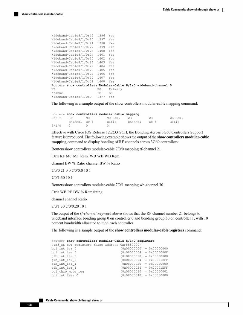
Wideband-Cable8/1/0:19 1396 YesWideband-Cable8/1/0:20 1397 YesWideband-Cable8/1/0:21 1398 YesWideband-Cable8/1/0:22 1399 YesWideband-Cable8/1/0:23 1400 YesWideband-Cable8/1/0:24 1401 YesWideband-Cable8/1/0:25 1402 YesWideband-Cable8/1/0:26 1403 YesWideband-Cable8/1/0:27 1404 YesWideband-Cable8/1/0:28 1405 YesWideband-Cable8/1/0:29 1406 YesWideband-Cable8/1/0:30 1407 YesWideband-Cable8/1/0:31 1408 YesRouter# show controllers Modular-Cable 8/1/0 wideband-channel 0WB BG Primarychannel ID BGWideband-Cable8/1/0:0 1377 Yes
The following is a sample output of the show controllers modular-cable mapping command:
router# show controllers modular-cable mappingCtrlr RF MC MC Rem. WB WB WB Rem.
channel BW % Ratio channel BW % Ratio5/1/0 2 0 0
Effective with Cisco IOS Release 12.2(33)SCH, the Bonding Across 3G60 Controllers Supportfeature is introduced. The following example shows the output of the show controllers modular-cablemapping command to display bonding of RF channels across 3G60 controllers:
Router#show controllers modular-cable 7/0/0 mapping rf-channel 21
Ctrlr RF MC MC Rem. WB WBWB Rem.
channel BW % Ratio channel BW % Ratio
7/0/0 21 0 0 7/0/0:0 10 1
7/0/1:30 10 1
Router#show controllers modular-cable 7/0/1 mapping wb-channel 30
Ctrlr WB RF BW % Remaining
channel channel Ratio
7/0/1 30 7/0/0:20 10 1
The output of the rf-channel keyword above shows that the RF channel number 21 belongs towideband interface bonding group 0 on controller 0 and bonding group 30 on controller 1, with 10percent bandwidth allocated to it on each controller.
The following is a sample output of the show controllers modular-cable registers command:
router# show controllers modular-Cable 5/1/0 registersJIB3_DS BPI registers (base address 0xF8880000)bpi_int_isr_0 [0x00000000] = 0x00000000bpi_int_ier_0 [0x00000004] = 0x0000000Fglb_int_isr_0 [0x00000010] = 0x00000000glb_int_ier_0 [0x00000014] = 0x00001EFFglb_int_isr_1 [0x00000020] = 0x00000000glb_int_ier_1 [0x00000024] = 0x00001EFFcol_chip_mode_reg [0x00000030] = 0x00000001bpi_int_fesr_0 [0x00000040] = 0x00000000
Cable Commands: show ch through show cr108
Cable Commands: show ch through show crshow controllers modular-cable
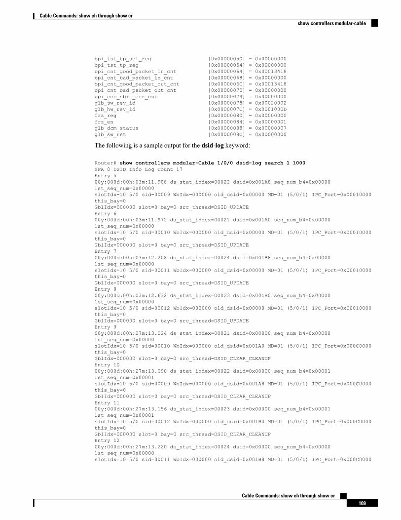
bpi_tst_tp_sel_reg [0x00000050] = 0x00000000bpi_tst_tp_reg [0x00000054] = 0x00000000bpi_cnt_good_packet_in_cnt [0x00000064] = 0x00013418bpi_cnt_bad_packet_in_cnt [0x00000068] = 0x00000000bpi_cnt_good_packet_out_cnt [0x0000006C] = 0x00013418bpi_cnt_bad_packet_out_cnt [0x00000070] = 0x00000000bpi_ecc_sbit_err_cnt [0x00000074] = 0x00000000glb_sw_rev_id [0x00000078] = 0x00020002glb_hw_rev_id [0x0000007C] = 0x0001000Dfrz_reg [0x00000080] = 0x00000000frz_en [0x00000084] = 0x00000001glb_dcm_status [0x00000088] = 0x00000007glb_sw_rst [0x0000008C] = 0x00000000
The following is a sample output for the dsid-log keyword:
Router# show controllers modular-Cable 1/0/0 dsid-log search 1 1000SPA 0 DSID Info Log Count 17Entry 500y:000d:00h:03m:11.908 ds_stat_index=00022 dsid=0x001A8 seq_num_b4=0x000001st_seq_num=0x00000slotIdx=10 5/0 sid=00009 WbIdx=000000 old_dsid=0x00000 MD=01 (5/0/1) IPC_Port=0x00010000this_bay=0GblIdx=000000 slot=0 bay=0 src_thread=DSID_UPDATEEntry 600y:000d:00h:03m:11.972 ds_stat_index=00021 dsid=0x001A0 seq_num_b4=0x000001st_seq_num=0x00000slotIdx=10 5/0 sid=00010 WbIdx=000000 old_dsid=0x00000 MD=01 (5/0/1) IPC_Port=0x00010000this_bay=0GblIdx=000000 slot=0 bay=0 src_thread=DSID_UPDATEEntry 700y:000d:00h:03m:12.208 ds_stat_index=00024 dsid=0x001B8 seq_num_b4=0x000001st_seq_num=0x00000slotIdx=10 5/0 sid=00011 WbIdx=000000 old_dsid=0x00000 MD=01 (5/0/1) IPC_Port=0x00010000this_bay=0GblIdx=000000 slot=0 bay=0 src_thread=DSID_UPDATEEntry 800y:000d:00h:03m:12.632 ds_stat_index=00023 dsid=0x001B0 seq_num_b4=0x000001st_seq_num=0x00000slotIdx=10 5/0 sid=00012 WbIdx=000000 old_dsid=0x00000 MD=01 (5/0/1) IPC_Port=0x00010000this_bay=0GblIdx=000000 slot=0 bay=0 src_thread=DSID_UPDATEEntry 900y:000d:00h:27m:13.024 ds_stat_index=00021 dsid=0x00000 seq_num_b4=0x000001st_seq_num=0x00000slotIdx=10 5/0 sid=00010 WbIdx=000000 old_dsid=0x001A0 MD=01 (5/0/1) IPC_Port=0x000C0000this_bay=0GblIdx=000000 slot=0 bay=0 src_thread=DSID_CLEAR_CLEANUPEntry 1000y:000d:00h:27m:13.090 ds_stat_index=00022 dsid=0x00000 seq_num_b4=0x000011st_seq_num=0x00001slotIdx=10 5/0 sid=00009 WbIdx=000000 old_dsid=0x001A8 MD=01 (5/0/1) IPC_Port=0x000C0000this_bay=0GblIdx=000000 slot=0 bay=0 src_thread=DSID_CLEAR_CLEANUPEntry 1100y:000d:00h:27m:13.156 ds_stat_index=00023 dsid=0x00000 seq_num_b4=0x000011st_seq_num=0x00001slotIdx=10 5/0 sid=00012 WbIdx=000000 old_dsid=0x001B0 MD=01 (5/0/1) IPC_Port=0x000C0000this_bay=0GblIdx=000000 slot=0 bay=0 src_thread=DSID_CLEAR_CLEANUPEntry 1200y:000d:00h:27m:13.220 ds_stat_index=00024 dsid=0x00000 seq_num_b4=0x000001st_seq_num=0x00000slotIdx=10 5/0 sid=00011 WbIdx=000000 old_dsid=0x001B8 MD=01 (5/0/1) IPC_Port=0x000C0000
Cable Commands: show ch through show cr109
Cable Commands: show ch through show crshow controllers modular-cable
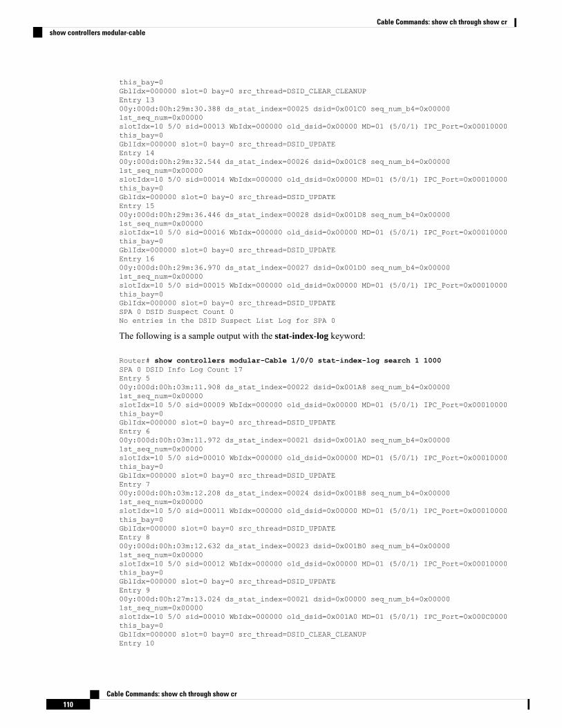
this_bay=0GblIdx=000000 slot=0 bay=0 src_thread=DSID_CLEAR_CLEANUPEntry 1300y:000d:00h:29m:30.388 ds_stat_index=00025 dsid=0x001C0 seq_num_b4=0x000001st_seq_num=0x00000slotIdx=10 5/0 sid=00013 WbIdx=000000 old_dsid=0x00000 MD=01 (5/0/1) IPC_Port=0x00010000this_bay=0GblIdx=000000 slot=0 bay=0 src_thread=DSID_UPDATEEntry 1400y:000d:00h:29m:32.544 ds_stat_index=00026 dsid=0x001C8 seq_num_b4=0x000001st_seq_num=0x00000slotIdx=10 5/0 sid=00014 WbIdx=000000 old_dsid=0x00000 MD=01 (5/0/1) IPC_Port=0x00010000this_bay=0GblIdx=000000 slot=0 bay=0 src_thread=DSID_UPDATEEntry 1500y:000d:00h:29m:36.446 ds_stat_index=00028 dsid=0x001D8 seq_num_b4=0x000001st_seq_num=0x00000slotIdx=10 5/0 sid=00016 WbIdx=000000 old_dsid=0x00000 MD=01 (5/0/1) IPC_Port=0x00010000this_bay=0GblIdx=000000 slot=0 bay=0 src_thread=DSID_UPDATEEntry 1600y:000d:00h:29m:36.970 ds_stat_index=00027 dsid=0x001D0 seq_num_b4=0x000001st_seq_num=0x00000slotIdx=10 5/0 sid=00015 WbIdx=000000 old_dsid=0x00000 MD=01 (5/0/1) IPC_Port=0x00010000this_bay=0GblIdx=000000 slot=0 bay=0 src_thread=DSID_UPDATESPA 0 DSID Suspect Count 0No entries in the DSID Suspect List Log for SPA 0
The following is a sample output with the stat-index-log keyword:
Router# show controllers modular-Cable 1/0/0 stat-index-log search 1 1000SPA 0 DSID Info Log Count 17Entry 500y:000d:00h:03m:11.908 ds_stat_index=00022 dsid=0x001A8 seq_num_b4=0x000001st_seq_num=0x00000slotIdx=10 5/0 sid=00009 WbIdx=000000 old_dsid=0x00000 MD=01 (5/0/1) IPC_Port=0x00010000this_bay=0GblIdx=000000 slot=0 bay=0 src_thread=DSID_UPDATEEntry 600y:000d:00h:03m:11.972 ds_stat_index=00021 dsid=0x001A0 seq_num_b4=0x000001st_seq_num=0x00000slotIdx=10 5/0 sid=00010 WbIdx=000000 old_dsid=0x00000 MD=01 (5/0/1) IPC_Port=0x00010000this_bay=0GblIdx=000000 slot=0 bay=0 src_thread=DSID_UPDATEEntry 700y:000d:00h:03m:12.208 ds_stat_index=00024 dsid=0x001B8 seq_num_b4=0x000001st_seq_num=0x00000slotIdx=10 5/0 sid=00011 WbIdx=000000 old_dsid=0x00000 MD=01 (5/0/1) IPC_Port=0x00010000this_bay=0GblIdx=000000 slot=0 bay=0 src_thread=DSID_UPDATEEntry 800y:000d:00h:03m:12.632 ds_stat_index=00023 dsid=0x001B0 seq_num_b4=0x000001st_seq_num=0x00000slotIdx=10 5/0 sid=00012 WbIdx=000000 old_dsid=0x00000 MD=01 (5/0/1) IPC_Port=0x00010000this_bay=0GblIdx=000000 slot=0 bay=0 src_thread=DSID_UPDATEEntry 900y:000d:00h:27m:13.024 ds_stat_index=00021 dsid=0x00000 seq_num_b4=0x000001st_seq_num=0x00000slotIdx=10 5/0 sid=00010 WbIdx=000000 old_dsid=0x001A0 MD=01 (5/0/1) IPC_Port=0x000C0000this_bay=0GblIdx=000000 slot=0 bay=0 src_thread=DSID_CLEAR_CLEANUPEntry 10
Cable Commands: show ch through show cr110
Cable Commands: show ch through show crshow controllers modular-cable
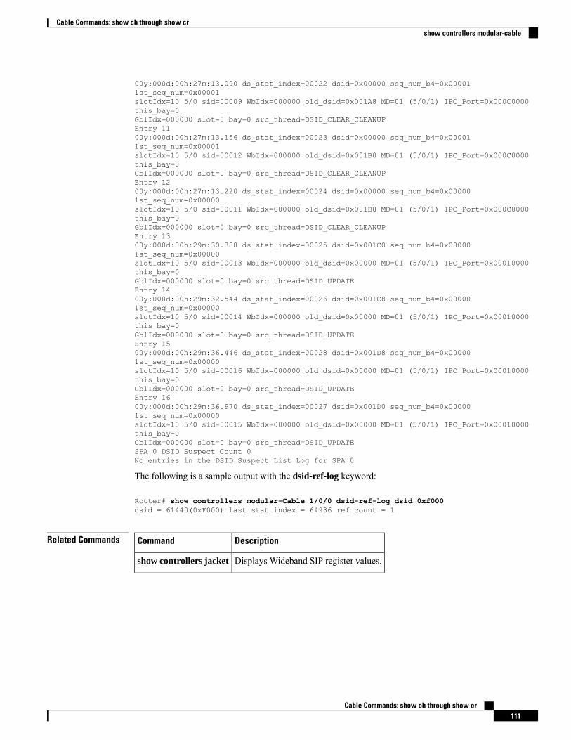
00y:000d:00h:27m:13.090 ds_stat_index=00022 dsid=0x00000 seq_num_b4=0x000011st_seq_num=0x00001slotIdx=10 5/0 sid=00009 WbIdx=000000 old_dsid=0x001A8 MD=01 (5/0/1) IPC_Port=0x000C0000this_bay=0GblIdx=000000 slot=0 bay=0 src_thread=DSID_CLEAR_CLEANUPEntry 1100y:000d:00h:27m:13.156 ds_stat_index=00023 dsid=0x00000 seq_num_b4=0x000011st_seq_num=0x00001slotIdx=10 5/0 sid=00012 WbIdx=000000 old_dsid=0x001B0 MD=01 (5/0/1) IPC_Port=0x000C0000this_bay=0GblIdx=000000 slot=0 bay=0 src_thread=DSID_CLEAR_CLEANUPEntry 1200y:000d:00h:27m:13.220 ds_stat_index=00024 dsid=0x00000 seq_num_b4=0x000001st_seq_num=0x00000slotIdx=10 5/0 sid=00011 WbIdx=000000 old_dsid=0x001B8 MD=01 (5/0/1) IPC_Port=0x000C0000this_bay=0GblIdx=000000 slot=0 bay=0 src_thread=DSID_CLEAR_CLEANUPEntry 1300y:000d:00h:29m:30.388 ds_stat_index=00025 dsid=0x001C0 seq_num_b4=0x000001st_seq_num=0x00000slotIdx=10 5/0 sid=00013 WbIdx=000000 old_dsid=0x00000 MD=01 (5/0/1) IPC_Port=0x00010000this_bay=0GblIdx=000000 slot=0 bay=0 src_thread=DSID_UPDATEEntry 1400y:000d:00h:29m:32.544 ds_stat_index=00026 dsid=0x001C8 seq_num_b4=0x000001st_seq_num=0x00000slotIdx=10 5/0 sid=00014 WbIdx=000000 old_dsid=0x00000 MD=01 (5/0/1) IPC_Port=0x00010000this_bay=0GblIdx=000000 slot=0 bay=0 src_thread=DSID_UPDATEEntry 1500y:000d:00h:29m:36.446 ds_stat_index=00028 dsid=0x001D8 seq_num_b4=0x000001st_seq_num=0x00000slotIdx=10 5/0 sid=00016 WbIdx=000000 old_dsid=0x00000 MD=01 (5/0/1) IPC_Port=0x00010000this_bay=0GblIdx=000000 slot=0 bay=0 src_thread=DSID_UPDATEEntry 1600y:000d:00h:29m:36.970 ds_stat_index=00027 dsid=0x001D0 seq_num_b4=0x000001st_seq_num=0x00000slotIdx=10 5/0 sid=00015 WbIdx=000000 old_dsid=0x00000 MD=01 (5/0/1) IPC_Port=0x00010000this_bay=0GblIdx=000000 slot=0 bay=0 src_thread=DSID_UPDATESPA 0 DSID Suspect Count 0No entries in the DSID Suspect List Log for SPA 0
The following is a sample output with the dsid-ref-log keyword:
Router# show controllers modular-Cable 1/0/0 dsid-ref-log dsid 0xf000dsid = 61440(0xF000) last_stat_index = 64936 ref_count = 1
Related Commands DescriptionCommand
Displays Wideband SIP register values.show controllers jacket
Cable Commands: show ch through show cr111
Cable Commands: show ch through show crshow controllers modular-cable
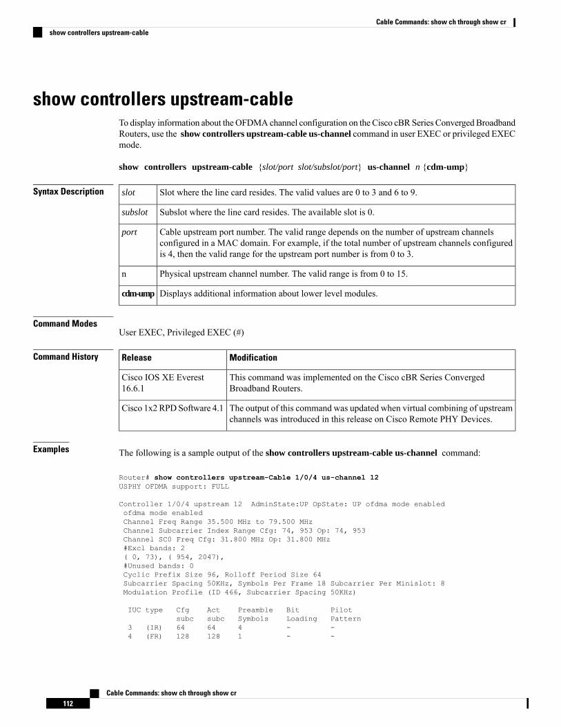
show controllers upstream-cableTo display information about theOFDMAchannel configuration on the Cisco cBRSeries Converged BroadbandRouters, use the show controllers upstream-cable us-channel command in user EXEC or privileged EXECmode.
show controllers upstream-cable {slot/port slot/subslot/port} us-channel n {cdm-ump}
Syntax Description Slot where the line card resides. The valid values are 0 to 3 and 6 to 9.slot
Subslot where the line card resides. The available slot is 0.subslot
Cable upstream port number. The valid range depends on the number of upstream channelsconfigured in a MAC domain. For example, if the total number of upstream channels configuredis 4, then the valid range for the upstream port number is from 0 to 3.
port
Physical upstream channel number. The valid range is from 0 to 15.n
Displays additional information about lower level modules.cdm-ump
Command ModesUser EXEC, Privileged EXEC (#)
Command History ModificationRelease
This command was implemented on the Cisco cBR Series ConvergedBroadband Routers.
Cisco IOS XE Everest16.6.1
The output of this command was updated when virtual combining of upstreamchannels was introduced in this release on Cisco Remote PHY Devices.
Cisco 1x2 RPDSoftware 4.1
Examples The following is a sample output of the show controllers upstream-cable us-channel command:
Router# show controllers upstream-Cable 1/0/4 us-channel 12USPHY OFDMA support: FULL
Controller 1/0/4 upstream 12 AdminState:UP OpState: UP ofdma mode enabledofdma mode enabledChannel Freq Range 35.500 MHz to 79.500 MHzChannel Subcarrier Index Range Cfg: 74, 953 Op: 74, 953Channel SC0 Freq Cfg: 31.800 MHz Op: 31.800 MHz#Excl bands: 2( 0, 73), ( 954, 2047),#Unused bands: 0Cyclic Prefix Size 96, Rolloff Period Size 64Subcarrier Spacing 50KHz, Symbols Per Frame 18 Subcarrier Per Minislot: 8Modulation Profile (ID 466, Subcarrier Spacing 50KHz)
IUC type Cfg Act Preamble Bit Pilotsubc subc Symbols Loading Pattern
3 (IR) 64 64 4 - -4 (FR) 128 128 1 - -
Cable Commands: show ch through show cr112
Cable Commands: show ch through show crshow controllers upstream-cable
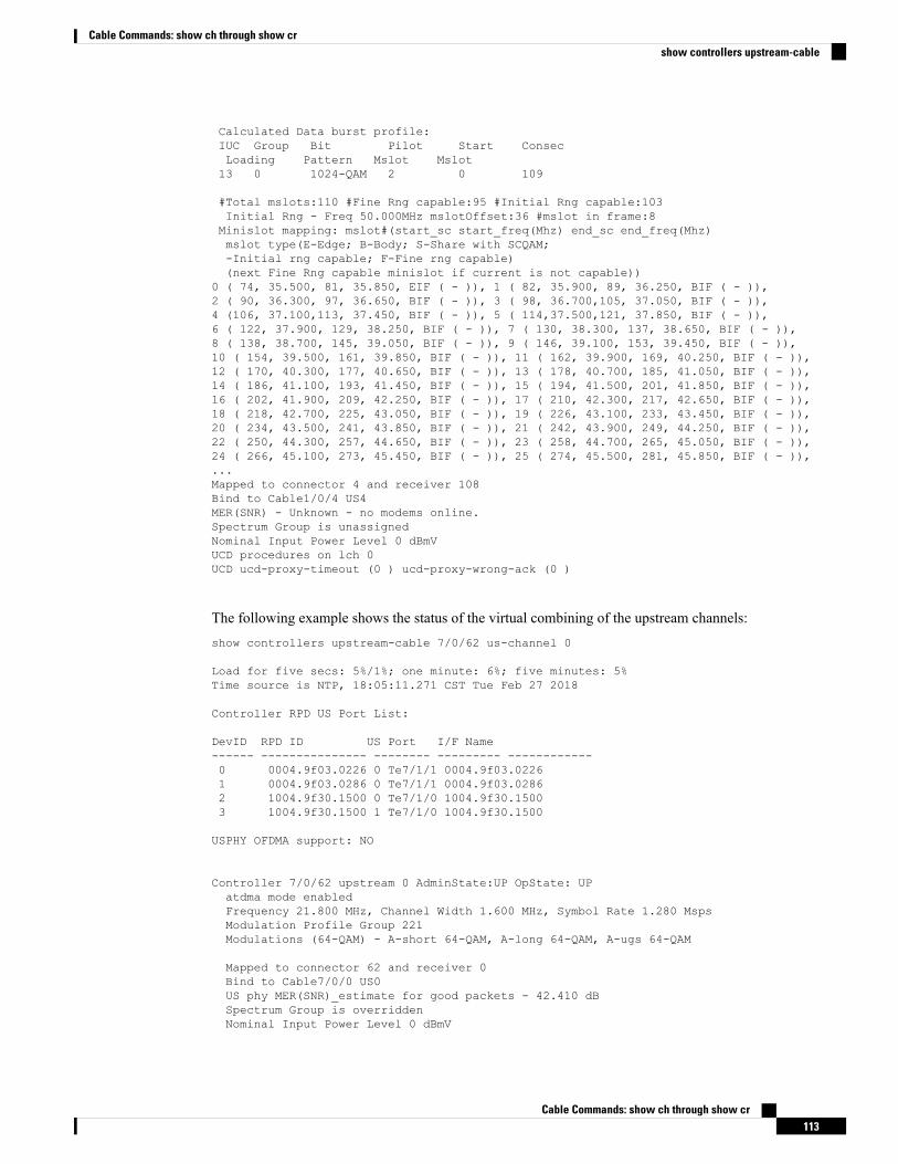
Calculated Data burst profile:IUC Group Bit Pilot Start ConsecLoading Pattern Mslot Mslot13 0 1024-QAM 2 0 109
#Total mslots:110 #Fine Rng capable:95 #Initial Rng capable:103Initial Rng - Freq 50.000MHz mslotOffset:36 #mslot in frame:8Minislot mapping: mslot#(start_sc start_freq(Mhz) end_sc end_freq(Mhz)mslot type(E-Edge; B-Body; S-Share with SCQAM;-Initial rng capable; F-Fine rng capable)(next Fine Rng capable minislot if current is not capable))
0 ( 74, 35.500, 81, 35.850, EIF ( - )), 1 ( 82, 35.900, 89, 36.250, BIF ( - )),2 ( 90, 36.300, 97, 36.650, BIF ( - )), 3 ( 98, 36.700,105, 37.050, BIF ( - )),4 (106, 37.100,113, 37.450, BIF ( - )), 5 ( 114,37.500,121, 37.850, BIF ( - )),6 ( 122, 37.900, 129, 38.250, BIF ( - )), 7 ( 130, 38.300, 137, 38.650, BIF ( - )),8 ( 138, 38.700, 145, 39.050, BIF ( - )), 9 ( 146, 39.100, 153, 39.450, BIF ( - )),10 ( 154, 39.500, 161, 39.850, BIF ( - )), 11 ( 162, 39.900, 169, 40.250, BIF ( - )),12 ( 170, 40.300, 177, 40.650, BIF ( - )), 13 ( 178, 40.700, 185, 41.050, BIF ( - )),14 ( 186, 41.100, 193, 41.450, BIF ( - )), 15 ( 194, 41.500, 201, 41.850, BIF ( - )),16 ( 202, 41.900, 209, 42.250, BIF ( - )), 17 ( 210, 42.300, 217, 42.650, BIF ( - )),18 ( 218, 42.700, 225, 43.050, BIF ( - )), 19 ( 226, 43.100, 233, 43.450, BIF ( - )),20 ( 234, 43.500, 241, 43.850, BIF ( - )), 21 ( 242, 43.900, 249, 44.250, BIF ( - )),22 ( 250, 44.300, 257, 44.650, BIF ( - )), 23 ( 258, 44.700, 265, 45.050, BIF ( - )),24 ( 266, 45.100, 273, 45.450, BIF ( - )), 25 ( 274, 45.500, 281, 45.850, BIF ( - )),...Mapped to connector 4 and receiver 108Bind to Cable1/0/4 US4MER(SNR) - Unknown - no modems online.Spectrum Group is unassignedNominal Input Power Level 0 dBmVUCD procedures on lch 0UCD ucd-proxy-timeout (0 ) ucd-proxy-wrong-ack (0 )
The following example shows the status of the virtual combining of the upstream channels:show controllers upstream-cable 7/0/62 us-channel 0
Load for five secs: 5%/1%; one minute: 6%; five minutes: 5%Time source is NTP, 18:05:11.271 CST Tue Feb 27 2018
Controller RPD US Port List:
DevID RPD ID US Port I/F Name------ --------------- -------- --------- ------------0 0004.9f03.0226 0 Te7/1/1 0004.9f03.02261 0004.9f03.0286 0 Te7/1/1 0004.9f03.02862 1004.9f30.1500 0 Te7/1/0 1004.9f30.15003 1004.9f30.1500 1 Te7/1/0 1004.9f30.1500
USPHY OFDMA support: NO
Controller 7/0/62 upstream 0 AdminState:UP OpState: UPatdma mode enabledFrequency 21.800 MHz, Channel Width 1.600 MHz, Symbol Rate 1.280 MspsModulation Profile Group 221Modulations (64-QAM) - A-short 64-QAM, A-long 64-QAM, A-ugs 64-QAM
Mapped to connector 62 and receiver 0Bind to Cable7/0/0 US0US phy MER(SNR)_estimate for good packets - 42.410 dBSpectrum Group is overriddenNominal Input Power Level 0 dBmV
Cable Commands: show ch through show cr113
Cable Commands: show ch through show crshow controllers upstream-cable
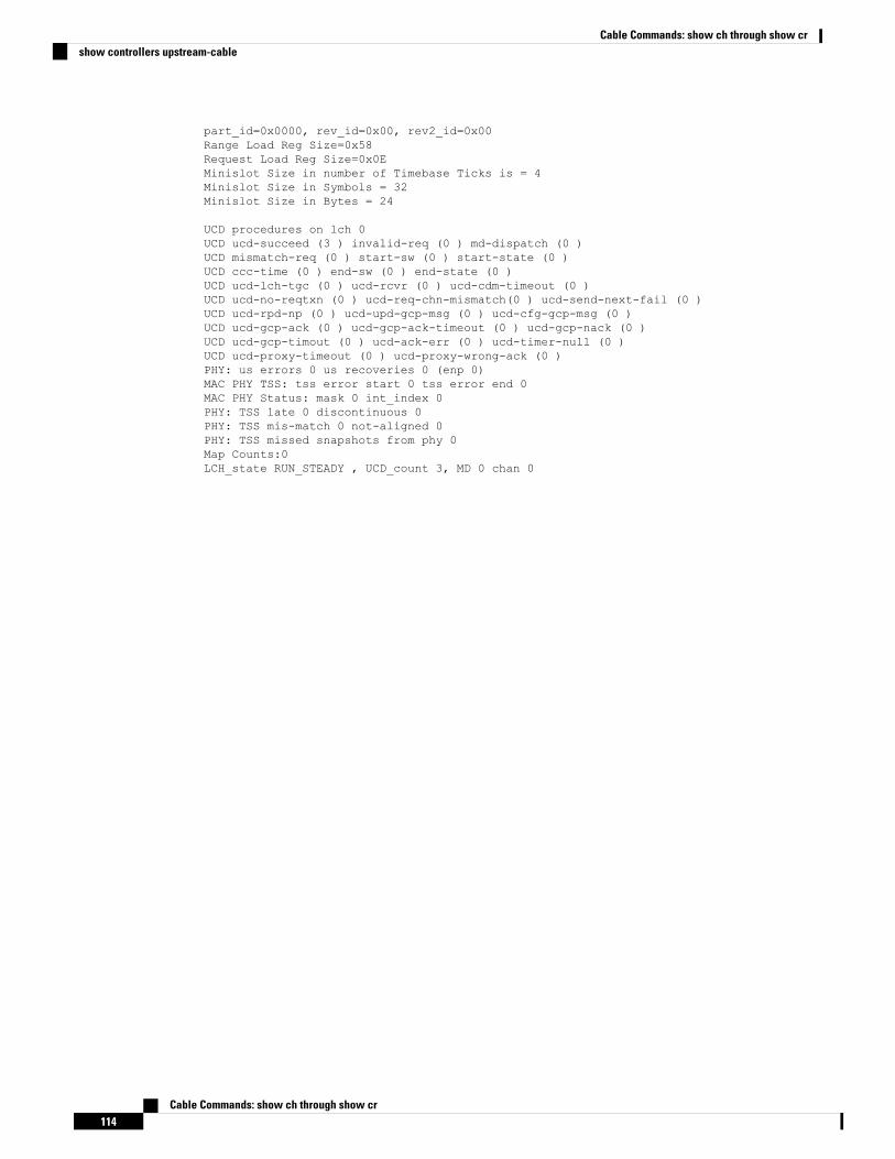
part_id=0x0000, rev_id=0x00, rev2_id=0x00Range Load Reg Size=0x58Request Load Reg Size=0x0EMinislot Size in number of Timebase Ticks is = 4Minislot Size in Symbols = 32Minislot Size in Bytes = 24
UCD procedures on lch 0UCD ucd-succeed (3 ) invalid-req (0 ) md-dispatch (0 )UCD mismatch-req (0 ) start-sw (0 ) start-state (0 )UCD ccc-time (0 ) end-sw (0 ) end-state (0 )UCD ucd-lch-tgc (0 ) ucd-rcvr (0 ) ucd-cdm-timeout (0 )UCD ucd-no-reqtxn (0 ) ucd-req-chn-mismatch(0 ) ucd-send-next-fail (0 )UCD ucd-rpd-np (0 ) ucd-upd-gcp-msg (0 ) ucd-cfg-gcp-msg (0 )UCD ucd-gcp-ack (0 ) ucd-gcp-ack-timeout (0 ) ucd-gcp-nack (0 )UCD ucd-gcp-timout (0 ) ucd-ack-err (0 ) ucd-timer-null (0 )UCD ucd-proxy-timeout (0 ) ucd-proxy-wrong-ack (0 )PHY: us errors 0 us recoveries 0 (enp 0)MAC PHY TSS: tss error start 0 tss error end 0MAC PHY Status: mask 0 int_index 0PHY: TSS late 0 discontinuous 0PHY: TSS mis-match 0 not-aligned 0PHY: TSS missed snapshots from phy 0Map Counts:0LCH_state RUN_STEADY , UCD_count 3, MD 0 chan 0
Cable Commands: show ch through show cr114
Cable Commands: show ch through show crshow controllers upstream-cable
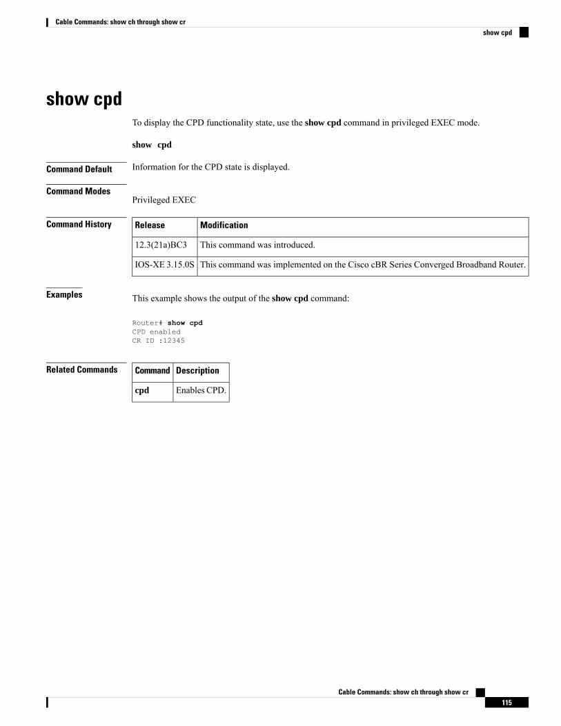
show cpdTo display the CPD functionality state, use the show cpd command in privileged EXEC mode.
show cpd
Command Default Information for the CPD state is displayed.
Command ModesPrivileged EXEC
Command History ModificationRelease
This command was introduced.12.3(21a)BC3
This command was implemented on the Cisco cBR Series Converged Broadband Router.IOS-XE 3.15.0S
Examples This example shows the output of the show cpd command:
Router# show cpdCPD enabledCR ID :12345
Related Commands DescriptionCommand
Enables CPD.cpd
Cable Commands: show ch through show cr115
Cable Commands: show ch through show crshow cpd
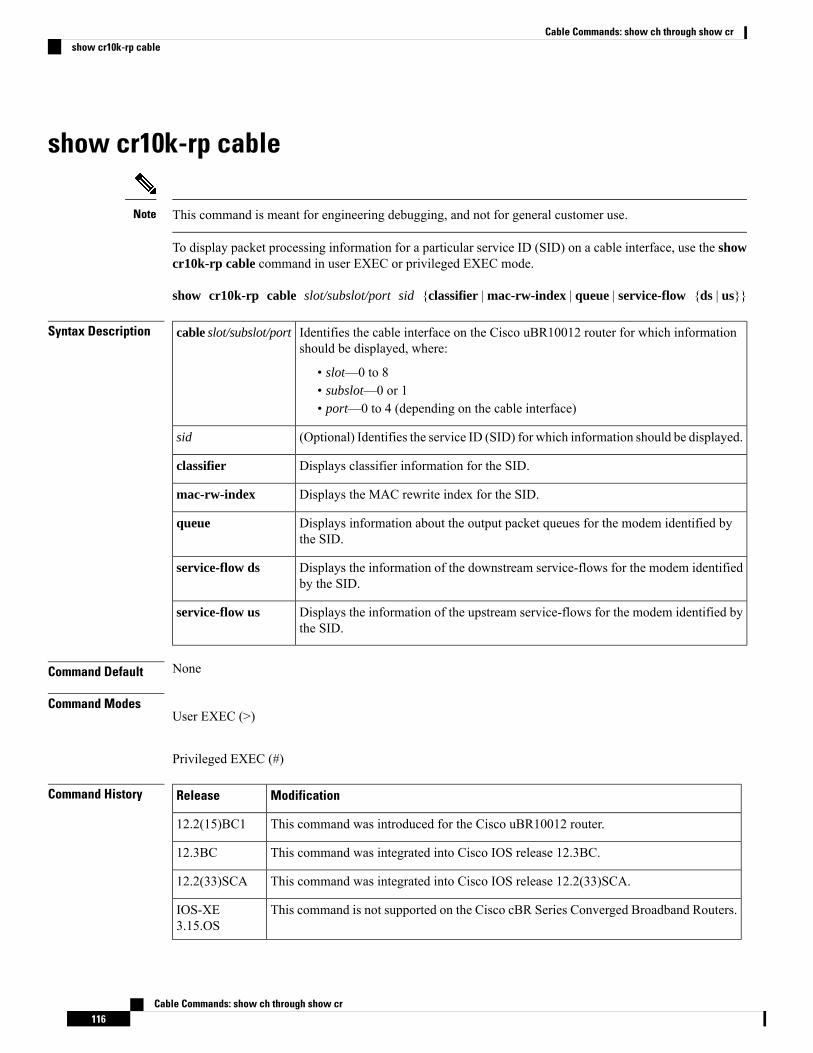
show cr10k-rp cable
This command is meant for engineering debugging, and not for general customer use.Note
To display packet processing information for a particular service ID (SID) on a cable interface, use the showcr10k-rp cable command in user EXEC or privileged EXEC mode.
show cr10k-rp cable slot/subslot/port sid {classifier | mac-rw-index | queue | service-flow {ds | us}}
Syntax Description Identifies the cable interface on the Cisco uBR10012 router for which informationshould be displayed, where:
• slot—0 to 8• subslot—0 or 1• port—0 to 4 (depending on the cable interface)
cable slot/subslot/port
(Optional) Identifies the service ID (SID) for which information should be displayed.sid
Displays classifier information for the SID.classifier
Displays the MAC rewrite index for the SID.mac-rw-index
Displays information about the output packet queues for the modem identified bythe SID.
queue
Displays the information of the downstream service-flows for the modem identifiedby the SID.
service-flow ds
Displays the information of the upstream service-flows for the modem identified bythe SID.
service-flow us
Command Default None
Command ModesUser EXEC (>)
Privileged EXEC (#)
Command History ModificationRelease
This command was introduced for the Cisco uBR10012 router.12.2(15)BC1
This command was integrated into Cisco IOS release 12.3BC.12.3BC
This command was integrated into Cisco IOS release 12.2(33)SCA.12.2(33)SCA
This command is not supported on the Cisco cBR Series Converged Broadband Routers.IOS-XE3.15.OS
Cable Commands: show ch through show cr116
Cable Commands: show ch through show crshow cr10k-rp cable
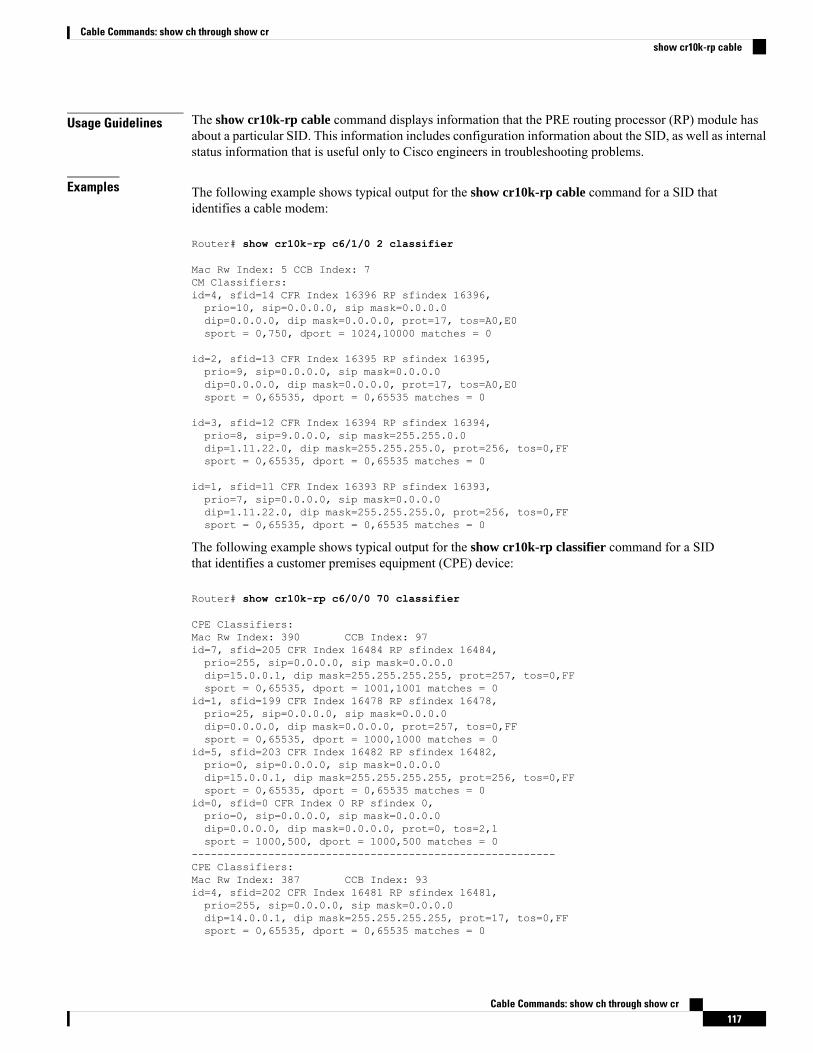
Usage Guidelines The show cr10k-rp cable command displays information that the PRE routing processor (RP) module hasabout a particular SID. This information includes configuration information about the SID, as well as internalstatus information that is useful only to Cisco engineers in troubleshooting problems.
Examples The following example shows typical output for the show cr10k-rp cable command for a SID thatidentifies a cable modem:
Router# show cr10k-rp c6/1/0 2 classifier
Mac Rw Index: 5 CCB Index: 7CM Classifiers:id=4, sfid=14 CFR Index 16396 RP sfindex 16396,prio=10, sip=0.0.0.0, sip mask=0.0.0.0dip=0.0.0.0, dip mask=0.0.0.0, prot=17, tos=A0,E0sport = 0,750, dport = 1024,10000 matches = 0
id=2, sfid=13 CFR Index 16395 RP sfindex 16395,prio=9, sip=0.0.0.0, sip mask=0.0.0.0dip=0.0.0.0, dip mask=0.0.0.0, prot=17, tos=A0,E0sport = 0,65535, dport = 0,65535 matches = 0
id=3, sfid=12 CFR Index 16394 RP sfindex 16394,prio=8, sip=9.0.0.0, sip mask=255.255.0.0dip=1.11.22.0, dip mask=255.255.255.0, prot=256, tos=0,FFsport = 0,65535, dport = 0,65535 matches = 0
id=1, sfid=11 CFR Index 16393 RP sfindex 16393,prio=7, sip=0.0.0.0, sip mask=0.0.0.0dip=1.11.22.0, dip mask=255.255.255.0, prot=256, tos=0,FFsport = 0,65535, dport = 0,65535 matches = 0
The following example shows typical output for the show cr10k-rp classifier command for a SIDthat identifies a customer premises equipment (CPE) device:
Router# show cr10k-rp c6/0/0 70 classifier
CPE Classifiers:Mac Rw Index: 390 CCB Index: 97id=7, sfid=205 CFR Index 16484 RP sfindex 16484,prio=255, sip=0.0.0.0, sip mask=0.0.0.0dip=15.0.0.1, dip mask=255.255.255.255, prot=257, tos=0,FFsport = 0,65535, dport = 1001,1001 matches = 0
id=1, sfid=199 CFR Index 16478 RP sfindex 16478,prio=25, sip=0.0.0.0, sip mask=0.0.0.0dip=0.0.0.0, dip mask=0.0.0.0, prot=257, tos=0,FFsport = 0,65535, dport = 1000,1000 matches = 0
id=5, sfid=203 CFR Index 16482 RP sfindex 16482,prio=0, sip=0.0.0.0, sip mask=0.0.0.0dip=15.0.0.1, dip mask=255.255.255.255, prot=256, tos=0,FFsport = 0,65535, dport = 0,65535 matches = 0
id=0, sfid=0 CFR Index 0 RP sfindex 0,prio=0, sip=0.0.0.0, sip mask=0.0.0.0dip=0.0.0.0, dip mask=0.0.0.0, prot=0, tos=2,1sport = 1000,500, dport = 1000,500 matches = 0
---------------------------------------------------------CPE Classifiers:Mac Rw Index: 387 CCB Index: 93id=4, sfid=202 CFR Index 16481 RP sfindex 16481,prio=255, sip=0.0.0.0, sip mask=0.0.0.0dip=14.0.0.1, dip mask=255.255.255.255, prot=17, tos=0,FFsport = 0,65535, dport = 0,65535 matches = 0
Cable Commands: show ch through show cr117
Cable Commands: show ch through show crshow cr10k-rp cable
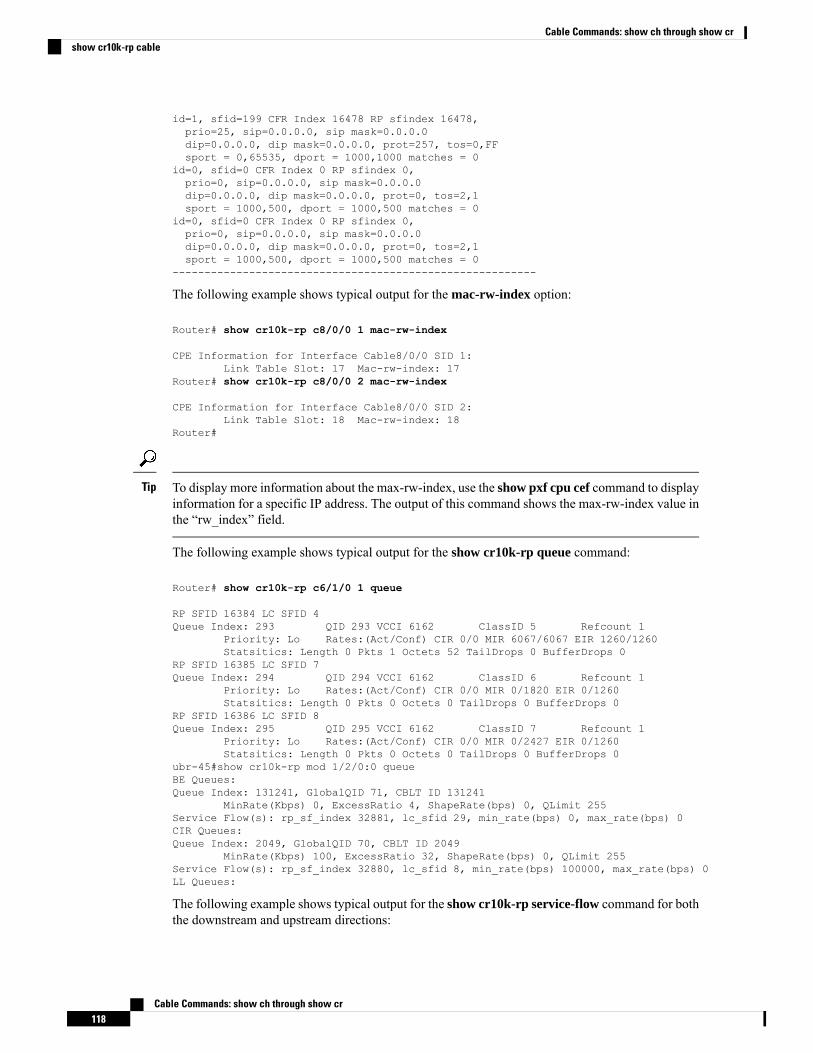
id=1, sfid=199 CFR Index 16478 RP sfindex 16478,prio=25, sip=0.0.0.0, sip mask=0.0.0.0dip=0.0.0.0, dip mask=0.0.0.0, prot=257, tos=0,FFsport = 0,65535, dport = 1000,1000 matches = 0
id=0, sfid=0 CFR Index 0 RP sfindex 0,prio=0, sip=0.0.0.0, sip mask=0.0.0.0dip=0.0.0.0, dip mask=0.0.0.0, prot=0, tos=2,1sport = 1000,500, dport = 1000,500 matches = 0
id=0, sfid=0 CFR Index 0 RP sfindex 0,prio=0, sip=0.0.0.0, sip mask=0.0.0.0dip=0.0.0.0, dip mask=0.0.0.0, prot=0, tos=2,1sport = 1000,500, dport = 1000,500 matches = 0
---------------------------------------------------------
The following example shows typical output for the mac-rw-index option:
Router# show cr10k-rp c8/0/0 1 mac-rw-index
CPE Information for Interface Cable8/0/0 SID 1:Link Table Slot: 17 Mac-rw-index: 17
Router# show cr10k-rp c8/0/0 2 mac-rw-index
CPE Information for Interface Cable8/0/0 SID 2:Link Table Slot: 18 Mac-rw-index: 18
Router#
To display more information about the max-rw-index, use the show pxf cpu cef command to displayinformation for a specific IP address. The output of this command shows the max-rw-index value inthe “rw_index” field.
Tip
The following example shows typical output for the show cr10k-rp queue command:
Router# show cr10k-rp c6/1/0 1 queue
RP SFID 16384 LC SFID 4Queue Index: 293 QID 293 VCCI 6162 ClassID 5 Refcount 1
Priority: Lo Rates:(Act/Conf) CIR 0/0 MIR 6067/6067 EIR 1260/1260Statsitics: Length 0 Pkts 1 Octets 52 TailDrops 0 BufferDrops 0
RP SFID 16385 LC SFID 7Queue Index: 294 QID 294 VCCI 6162 ClassID 6 Refcount 1
Priority: Lo Rates:(Act/Conf) CIR 0/0 MIR 0/1820 EIR 0/1260Statsitics: Length 0 Pkts 0 Octets 0 TailDrops 0 BufferDrops 0
RP SFID 16386 LC SFID 8Queue Index: 295 QID 295 VCCI 6162 ClassID 7 Refcount 1
Priority: Lo Rates:(Act/Conf) CIR 0/0 MIR 0/2427 EIR 0/1260Statsitics: Length 0 Pkts 0 Octets 0 TailDrops 0 BufferDrops 0
ubr-45#show cr10k-rp mod 1/2/0:0 queueBE Queues:Queue Index: 131241, GlobalQID 71, CBLT ID 131241
MinRate(Kbps) 0, ExcessRatio 4, ShapeRate(bps) 0, QLimit 255Service Flow(s): rp_sf_index 32881, lc_sfid 29, min_rate(bps) 0, max_rate(bps) 0CIR Queues:Queue Index: 2049, GlobalQID 70, CBLT ID 2049
MinRate(Kbps) 100, ExcessRatio 32, ShapeRate(bps) 0, QLimit 255Service Flow(s): rp_sf_index 32880, lc_sfid 8, min_rate(bps) 100000, max_rate(bps) 0LL Queues:
The following example shows typical output for the show cr10k-rp service-flow command for boththe downstream and upstream directions:
Cable Commands: show ch through show cr118
Cable Commands: show ch through show crshow cr10k-rp cable
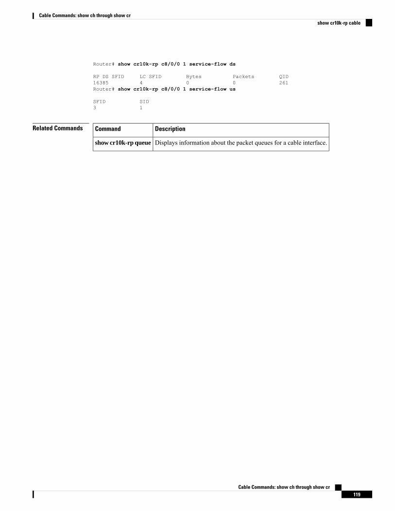
Router# show cr10k-rp c8/0/0 1 service-flow ds
RP DS SFID LC SFID Bytes Packets QID16385 4 0 0 261Router# show cr10k-rp c8/0/0 1 service-flow us
SFID SID3 1
Related Commands DescriptionCommand
Displays information about the packet queues for a cable interface.show cr10k-rp queue
Cable Commands: show ch through show cr119
Cable Commands: show ch through show crshow cr10k-rp cable
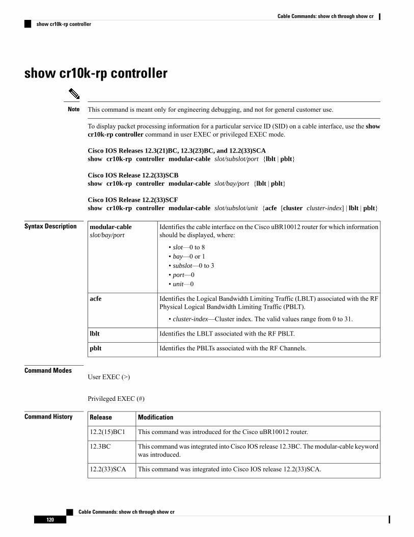
show cr10k-rp controller
This command is meant only for engineering debugging, and not for general customer use.Note
To display packet processing information for a particular service ID (SID) on a cable interface, use the showcr10k-rp controller command in user EXEC or privileged EXEC mode.
Cisco IOS Releases 12.3(21)BC, 12.3(23)BC, and 12.2(33)SCAshow cr10k-rp controller modular-cable slot/subslot/port {lblt | pblt}
Cisco IOS Release 12.2(33)SCBshow cr10k-rp controller modular-cable slot/bay/port {lblt | pblt}
Cisco IOS Release 12.2(33)SCFshow cr10k-rp controller modular-cable slot/subslot/unit {acfe [cluster cluster-index] | lblt | pblt}
Syntax Description Identifies the cable interface on the Cisco uBR10012 router for which informationshould be displayed, where:
• slot—0 to 8• bay—0 or 1• subslot—0 to 3• port—0• unit—0
modular-cableslot/bay/port
Identifies the Logical Bandwidth Limiting Traffic (LBLT) associated with the RFPhysical Logical Bandwidth Limiting Traffic (PBLT).
• cluster-index—Cluster index. The valid values range from 0 to 31.
acfe
Identifies the LBLT associated with the RF PBLT.lblt
Identifies the PBLTs associated with the RF Channels.pblt
Command ModesUser EXEC (>)
Privileged EXEC (#)
Command History ModificationRelease
This command was introduced for the Cisco uBR10012 router.12.2(15)BC1
This command was integrated into Cisco IOS release 12.3BC. Themodular-cable keywordwas introduced.
12.3BC
This command was integrated into Cisco IOS release 12.2(33)SCA.12.2(33)SCA
Cable Commands: show ch through show cr120
Cable Commands: show ch through show crshow cr10k-rp controller
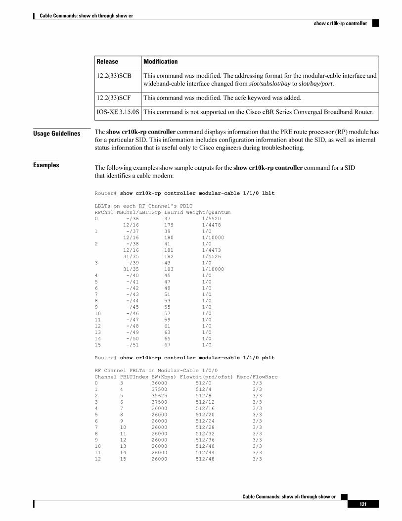
ModificationRelease
This command was modified. The addressing format for the modular-cable interface andwideband-cable interface changed from slot/subslot/bay to slot/bay/port.
12.2(33)SCB
This command was modified. The acfe keyword was added.12.2(33)SCF
This command is not supported on the Cisco cBR Series Converged Broadband Router.IOS-XE 3.15.0S
Usage Guidelines The show cr10k-rp controller command displays information that the PRE route processor (RP) module hasfor a particular SID. This information includes configuration information about the SID, as well as internalstatus information that is useful only to Cisco engineers during troubleshooting.
Examples The following examples show sample outputs for the show cr10k-rp controller command for a SIDthat identifies a cable modem:
Router# show cr10k-rp controller modular-cable 1/1/0 lblt
LBLTs on each RF Channel's PBLTRFChnl WBChnl/LBLTGrp LBLTId Weight/Quantum0 -/36 37 1/5520
12/16 179 1/44781 -/37 39 1/0
12/16 180 1/100002 -/38 41 1/0
12/16 181 1/447331/35 182 1/5526
3 -/39 43 1/031/35 183 1/10000
4 -/40 45 1/05 -/41 47 1/06 -/42 49 1/07 -/43 51 1/08 -/44 53 1/09 -/45 55 1/010 -/46 57 1/011 -/47 59 1/012 -/48 61 1/013 -/49 63 1/014 -/50 65 1/015 -/51 67 1/0
Router# show cr10k-rp controller modular-cable 1/1/0 pblt
RF Channel PBLTs on Modular-Cable 1/0/0Channel PBLTIndex BW(Kbps) Flowbit(prd/ofst) Rsrc/FlowRsrc0 3 36000 512/0 3/31 4 37500 512/4 3/32 5 35625 512/8 3/33 6 37500 512/12 3/34 7 26000 512/16 3/35 8 26000 512/20 3/36 9 26000 512/24 3/37 10 26000 512/28 3/38 11 26000 512/32 3/39 12 26000 512/36 3/310 13 26000 512/40 3/311 14 26000 512/44 3/312 15 26000 512/48 3/3
Cable Commands: show ch through show cr121
Cable Commands: show ch through show crshow cr10k-rp controller
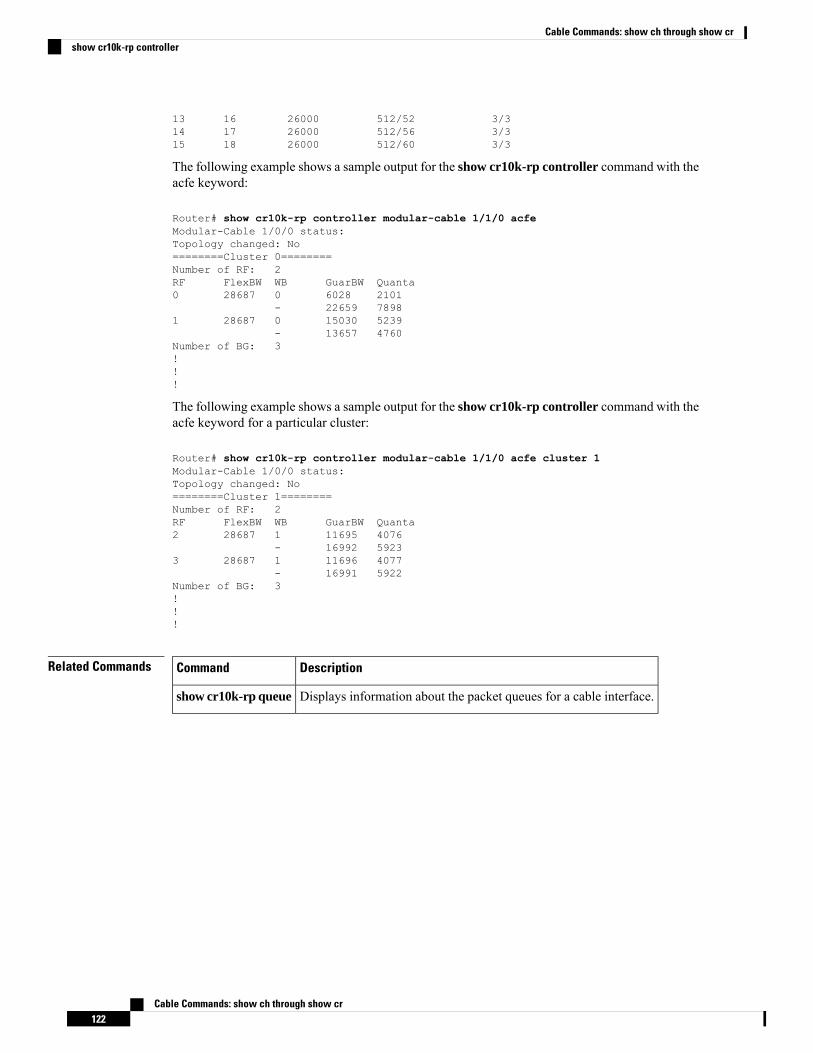
13 16 26000 512/52 3/314 17 26000 512/56 3/315 18 26000 512/60 3/3
The following example shows a sample output for the show cr10k-rp controller command with theacfe keyword:
Router# show cr10k-rp controller modular-cable 1/1/0 acfeModular-Cable 1/0/0 status:Topology changed: No========Cluster 0========Number of RF: 2RF FlexBW WB GuarBW Quanta0 28687 0 6028 2101
- 22659 78981 28687 0 15030 5239
- 13657 4760Number of BG: 3!!!
The following example shows a sample output for the show cr10k-rp controller command with theacfe keyword for a particular cluster:
Router# show cr10k-rp controller modular-cable 1/1/0 acfe cluster 1Modular-Cable 1/0/0 status:Topology changed: No========Cluster 1========Number of RF: 2RF FlexBW WB GuarBW Quanta2 28687 1 11695 4076
- 16992 59233 28687 1 11696 4077
- 16991 5922Number of BG: 3!!!
Related Commands DescriptionCommand
Displays information about the packet queues for a cable interface.show cr10k-rp queue
Cable Commands: show ch through show cr122
Cable Commands: show ch through show crshow cr10k-rp controller
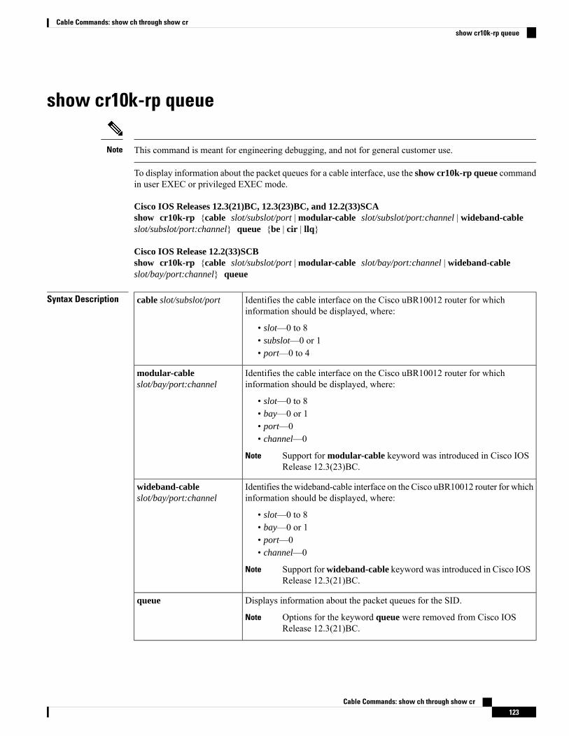
show cr10k-rp queue
This command is meant for engineering debugging, and not for general customer use.Note
To display information about the packet queues for a cable interface, use the show cr10k-rp queue commandin user EXEC or privileged EXEC mode.
Cisco IOS Releases 12.3(21)BC, 12.3(23)BC, and 12.2(33)SCAshow cr10k-rp {cable slot/subslot/port | modular-cable slot/subslot/port:channel | wideband-cableslot/subslot/port:channel} queue {be | cir | llq}
Cisco IOS Release 12.2(33)SCBshow cr10k-rp {cable slot/subslot/port | modular-cable slot/bay/port:channel | wideband-cableslot/bay/port:channel} queue
Syntax Description Identifies the cable interface on the Cisco uBR10012 router for whichinformation should be displayed, where:
• slot—0 to 8• subslot—0 or 1• port—0 to 4
cable slot/subslot/port
Identifies the cable interface on the Cisco uBR10012 router for whichinformation should be displayed, where:
• slot—0 to 8• bay—0 or 1• port—0• channel—0
Support for modular-cable keyword was introduced in Cisco IOSRelease 12.3(23)BC.
Note
modular-cableslot/bay/port:channel
Identifies the wideband-cable interface on the Cisco uBR10012 router for whichinformation should be displayed, where:
• slot—0 to 8• bay—0 or 1• port—0• channel—0
Support forwideband-cable keyword was introduced in Cisco IOSRelease 12.3(21)BC.
Note
wideband-cableslot/bay/port:channel
Displays information about the packet queues for the SID.
Options for the keyword queue were removed from Cisco IOSRelease 12.3(21)BC.
Note
queue
Cable Commands: show ch through show cr123
Cable Commands: show ch through show crshow cr10k-rp queue
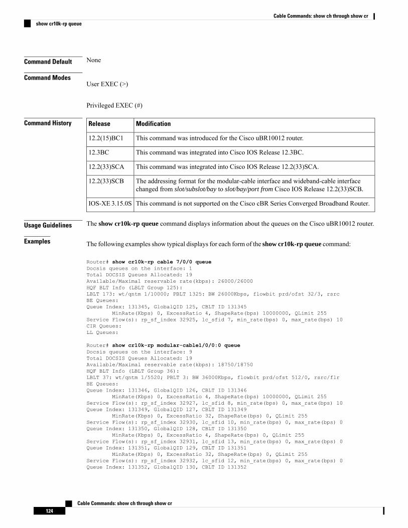
Command Default None
Command ModesUser EXEC (>)
Privileged EXEC (#)
Command History ModificationRelease
This command was introduced for the Cisco uBR10012 router.12.2(15)BC1
This command was integrated into Cisco IOS Release 12.3BC.12.3BC
This command was integrated into Cisco IOS Release 12.2(33)SCA.12.2(33)SCA
The addressing format for the modular-cable interface and wideband-cable interfacechanged from slot/subslot/bay to slot/bay/port from Cisco IOS Release 12.2(33)SCB.
12.2(33)SCB
This command is not supported on the Cisco cBR Series Converged Broadband Router.IOS-XE 3.15.0S
Usage Guidelines The show cr10k-rp queue command displays information about the queues on the Cisco uBR10012 router.
Examples The following examples show typical displays for each form of the show cr10k-rp queue command:
Router# show cr10k-rp cable 7/0/0 queueDocsis queues on the interface: 1Total DOCSIS Queues Allocated: 19Available/Maximal reservable rate(kbps): 26000/26000HQF BLT Info (LBLT Group 125):LBLT 173: wt/qntm 1/10000; PBLT 1325: BW 26000Kbps, flowbit prd/ofst 32/3, rsrcBE Queues:Queue Index: 131345, GlobalQID 125, CBLT ID 131345
MinRate(Kbps) 0, ExcessRatio 4, ShapeRate(bps) 10000000, QLimit 255Service Flow(s): rp_sf_index 32925, lc_sfid 7, min_rate(bps) 0, max_rate(bps) 10CIR Queues:LL Queues:
Router# show cr10k-rp modular-cable1/0/0:0 queueDocsis queues on the interface: 9Total DOCSIS Queues Allocated: 19Available/Maximal reservable rate(kbps): 18750/18750HQF BLT Info (LBLT Group 36):LBLT 37: wt/qntm 1/5520; PBLT 3: BW 36000Kbps, flowbit prd/ofst 512/0, rsrc/flrBE Queues:Queue Index: 131346, GlobalQID 126, CBLT ID 131346
MinRate(Kbps) 0, ExcessRatio 4, ShapeRate(bps) 10000000, QLimit 255Service Flow(s): rp_sf_index 32927, lc_sfid 8, min_rate(bps) 0, max_rate(bps) 10Queue Index: 131349, GlobalQID 127, CBLT ID 131349
MinRate(Kbps) 0, ExcessRatio 32, ShapeRate(bps) 0, QLimit 255Service Flow(s): rp_sf_index 32930, lc_sfid 10, min_rate(bps) 0, max_rate(bps) 0Queue Index: 131350, GlobalQID 128, CBLT ID 131350
MinRate(Kbps) 0, ExcessRatio 4, ShapeRate(bps) 0, QLimit 255Service Flow(s): rp_sf_index 32931, lc_sfid 13, min_rate(bps) 0, max_rate(bps) 0Queue Index: 131351, GlobalQID 129, CBLT ID 131351
MinRate(Kbps) 0, ExcessRatio 32, ShapeRate(bps) 0, QLimit 255Service Flow(s): rp_sf_index 32932, lc_sfid 12, min_rate(bps) 0, max_rate(bps) 0Queue Index: 131352, GlobalQID 130, CBLT ID 131352
Cable Commands: show ch through show cr124
Cable Commands: show ch through show crshow cr10k-rp queue
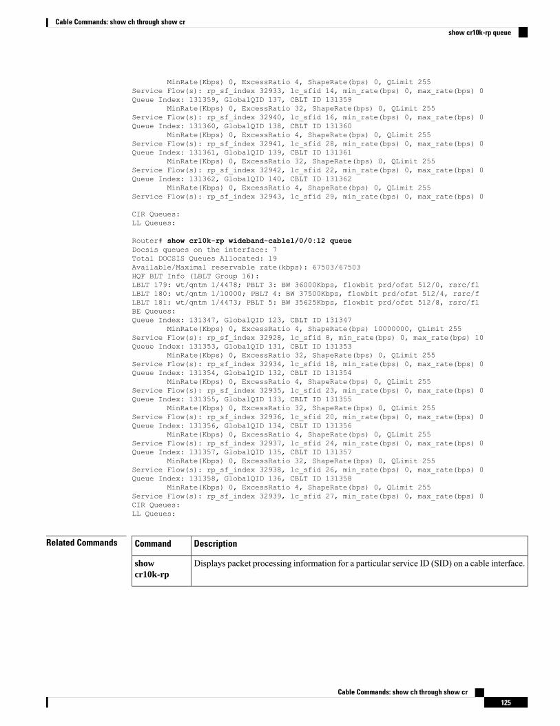
MinRate(Kbps) 0, ExcessRatio 4, ShapeRate(bps) 0, QLimit 255Service Flow(s): rp_sf_index 32933, lc_sfid 14, min_rate(bps) 0, max_rate(bps) 0Queue Index: 131359, GlobalQID 137, CBLT ID 131359
MinRate(Kbps) 0, ExcessRatio 32, ShapeRate(bps) 0, QLimit 255Service Flow(s): rp_sf_index 32940, lc_sfid 16, min_rate(bps) 0, max_rate(bps) 0Queue Index: 131360, GlobalQID 138, CBLT ID 131360
MinRate(Kbps) 0, ExcessRatio 4, ShapeRate(bps) 0, QLimit 255Service Flow(s): rp_sf_index 32941, lc_sfid 28, min_rate(bps) 0, max_rate(bps) 0Queue Index: 131361, GlobalQID 139, CBLT ID 131361
MinRate(Kbps) 0, ExcessRatio 32, ShapeRate(bps) 0, QLimit 255Service Flow(s): rp_sf_index 32942, lc_sfid 22, min_rate(bps) 0, max_rate(bps) 0Queue Index: 131362, GlobalQID 140, CBLT ID 131362
MinRate(Kbps) 0, ExcessRatio 4, ShapeRate(bps) 0, QLimit 255Service Flow(s): rp_sf_index 32943, lc_sfid 29, min_rate(bps) 0, max_rate(bps) 0
CIR Queues:LL Queues:
Router# show cr10k-rp wideband-cable1/0/0:12 queueDocsis queues on the interface: 7Total DOCSIS Queues Allocated: 19Available/Maximal reservable rate(kbps): 67503/67503HQF BLT Info (LBLT Group 16):LBLT 179: wt/qntm 1/4478; PBLT 3: BW 36000Kbps, flowbit prd/ofst 512/0, rsrc/flLBLT 180: wt/qntm 1/10000; PBLT 4: BW 37500Kbps, flowbit prd/ofst 512/4, rsrc/fLBLT 181: wt/qntm 1/4473; PBLT 5: BW 35625Kbps, flowbit prd/ofst 512/8, rsrc/flBE Queues:Queue Index: 131347, GlobalQID 123, CBLT ID 131347
MinRate(Kbps) 0, ExcessRatio 4, ShapeRate(bps) 10000000, QLimit 255Service Flow(s): rp_sf_index 32928, lc_sfid 8, min_rate(bps) 0, max_rate(bps) 10Queue Index: 131353, GlobalQID 131, CBLT ID 131353
MinRate(Kbps) 0, ExcessRatio 32, ShapeRate(bps) 0, QLimit 255Service Flow(s): rp_sf_index 32934, lc_sfid 18, min_rate(bps) 0, max_rate(bps) 0Queue Index: 131354, GlobalQID 132, CBLT ID 131354
MinRate(Kbps) 0, ExcessRatio 4, ShapeRate(bps) 0, QLimit 255Service Flow(s): rp_sf_index 32935, lc_sfid 23, min_rate(bps) 0, max_rate(bps) 0Queue Index: 131355, GlobalQID 133, CBLT ID 131355
MinRate(Kbps) 0, ExcessRatio 32, ShapeRate(bps) 0, QLimit 255Service Flow(s): rp_sf_index 32936, lc_sfid 20, min_rate(bps) 0, max_rate(bps) 0Queue Index: 131356, GlobalQID 134, CBLT ID 131356
MinRate(Kbps) 0, ExcessRatio 4, ShapeRate(bps) 0, QLimit 255Service Flow(s): rp_sf_index 32937, lc_sfid 24, min_rate(bps) 0, max_rate(bps) 0Queue Index: 131357, GlobalQID 135, CBLT ID 131357
MinRate(Kbps) 0, ExcessRatio 32, ShapeRate(bps) 0, QLimit 255Service Flow(s): rp_sf_index 32938, lc_sfid 26, min_rate(bps) 0, max_rate(bps) 0Queue Index: 131358, GlobalQID 136, CBLT ID 131358
MinRate(Kbps) 0, ExcessRatio 4, ShapeRate(bps) 0, QLimit 255Service Flow(s): rp_sf_index 32939, lc_sfid 27, min_rate(bps) 0, max_rate(bps) 0CIR Queues:LL Queues:
Related Commands DescriptionCommand
Displays packet processing information for a particular service ID (SID) on a cable interface.showcr10k-rp
Cable Commands: show ch through show cr125
Cable Commands: show ch through show crshow cr10k-rp queue
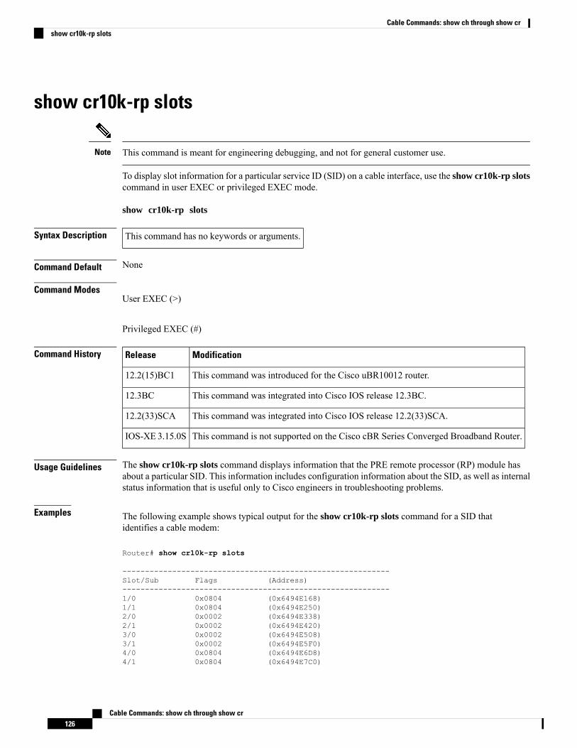
show cr10k-rp slots
This command is meant for engineering debugging, and not for general customer use.Note
To display slot information for a particular service ID (SID) on a cable interface, use the show cr10k-rp slotscommand in user EXEC or privileged EXEC mode.
show cr10k-rp slots
Syntax Description This command has no keywords or arguments.
Command Default None
Command ModesUser EXEC (>)
Privileged EXEC (#)
Command History ModificationRelease
This command was introduced for the Cisco uBR10012 router.12.2(15)BC1
This command was integrated into Cisco IOS release 12.3BC.12.3BC
This command was integrated into Cisco IOS release 12.2(33)SCA.12.2(33)SCA
This command is not supported on the Cisco cBR Series Converged Broadband Router.IOS-XE 3.15.0S
Usage Guidelines The show cr10k-rp slots command displays information that the PRE remote processor (RP) module hasabout a particular SID. This information includes configuration information about the SID, as well as internalstatus information that is useful only to Cisco engineers in troubleshooting problems.
Examples The following example shows typical output for the show cr10k-rp slots command for a SID thatidentifies a cable modem:
Router# show cr10k-rp slots
-----------------------------------------------------------Slot/Sub Flags (Address)-----------------------------------------------------------1/0 0x0804 (0x6494E168)1/1 0x0804 (0x6494E250)2/0 0x0002 (0x6494E338)2/1 0x0002 (0x6494E420)3/0 0x0002 (0x6494E508)3/1 0x0002 (0x6494E5F0)4/0 0x0804 (0x6494E6D8)4/1 0x0804 (0x6494E7C0)
Cable Commands: show ch through show cr126
Cable Commands: show ch through show crshow cr10k-rp slots
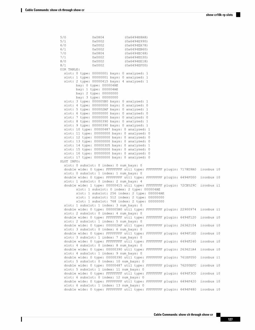
5/0 0x0804 (0x6494E8A8)5/1 0x0002 (0x6494E990)6/0 0x0002 (0x6494EA78)6/1 0x0002 (0x6494EB60)7/0 0x0804 (0x6494EC48)7/1 0x0002 (0x6494ED30)8/0 0x0002 (0x6494EE18)8/1 0x0002 (0x6494EF00)OIR TABLE:slot: 0 type: 00000001 bays: 0 analyzed: 1slot: 1 type: 00000001 bays: 0 analyzed: 1slot: 2 type: 00000415 bays: 4 analyzed: 1
bay: 0 type: 000004AEbay: 1 type: 000004AEbay: 2 type: 00000000bay: 3 type: 00000000
slot: 3 type: 000005B0 bays: 0 analyzed: 1slot: 4 type: 00000000 bays: 0 analyzed: 0slot: 5 type: 000002AF bays: 0 analyzed: 1slot: 6 type: 00000000 bays: 0 analyzed: 0slot: 7 type: 00000000 bays: 0 analyzed: 0slot: 8 type: 00000390 bays: 0 analyzed: 1slot: 9 type: 00000390 bays: 0 analyzed: 1slot: 10 type: 00000487 bays: 0 analyzed: 1slot: 11 type: 00000000 bays: 0 analyzed: 0slot: 12 type: 00000000 bays: 0 analyzed: 0slot: 13 type: 00000000 bays: 0 analyzed: 0slot: 14 type: 000003D5 bays: 0 analyzed: 1slot: 15 type: 00000000 bays: 0 analyzed: 0slot: 16 type: 00000000 bays: 0 analyzed: 0slot: 17 type: 00000000 bays: 0 analyzed: 0
SLOT INFO:slot: 0 subslot: 0 index: 0 num_bays: 0double wide: 0 type: FFFFFFFF util type: FFFFFFFF plugin: 7178D9A0 ironbus i0slot: 0 subslot: 1 index: 1 num_bays: 0double wide: 0 type: FFFFFFFF util type: FFFFFFFF plugin: 6494F000 ironbus i0slot: 1 subslot: 0 index: 2 num_bays: 4double wide: 1 type: 00000415 util type: FFFFFFFF plugin: 72CB529C ironbus i1
slot: 1 subslot: 0 index: 2 type: 000004AEslot: 1 subslot: 256 index: 2 type: 000004AEslot: 1 subslot: 512 index: 2 type: 00000000slot: 1 subslot: 768 index: 2 type: 00000000
slot: 1 subslot: 1 index: 3 num_bays: 0double wide: 0 type: 000005B0 util type: FFFFFFFF plugin: 22900974 ironbus i1slot: 2 subslot: 0 index: 4 num_bays: 0double wide: 0 type: FFFFFFFF util type: FFFFFFFF plugin: 6494F120 ironbus i0slot: 2 subslot: 1 index: 5 num_bays: 0double wide: 0 type: 000002AF util type: FFFFFFFF plugin: 26362104 ironbus i0slot: 3 subslot: 0 index: 6 num_bays: 0double wide: 0 type: FFFFFFFF util type: FFFFFFFF plugin: 6494F1E0 ironbus i0slot: 3 subslot: 1 index: 7 num_bays: 0double wide: 0 type: FFFFFFFF util type: FFFFFFFF plugin: 6494F240 ironbus i0slot: 4 subslot: 0 index: 8 num_bays: 0double wide: 0 type: 00000390 util type: FFFFFFFF plugin: 263621A4 ironbus i0slot: 4 subslot: 1 index: 9 num_bays: 0double wide: 0 type: 00000390 util type: FFFFFFFF plugin: 761EF050 ironbus i1slot: 5 subslot: 0 index: 10 num_bays: 0double wide: 0 type: 00000487 util type: FFFFFFFF plugin: 76200EFC ironbus i0slot: 5 subslot: 1 index: 11 num_bays: 0double wide: 0 type: FFFFFFFF util type: FFFFFFFF plugin: 6494F3C0 ironbus i0slot: 6 subslot: 0 index: 12 num_bays: 0double wide: 0 type: FFFFFFFF util type: FFFFFFFF plugin: 6494F420 ironbus i0slot: 6 subslot: 1 index: 13 num_bays: 0double wide: 0 type: FFFFFFFF util type: FFFFFFFF plugin: 6494F480 ironbus i0
Cable Commands: show ch through show cr127
Cable Commands: show ch through show crshow cr10k-rp slots
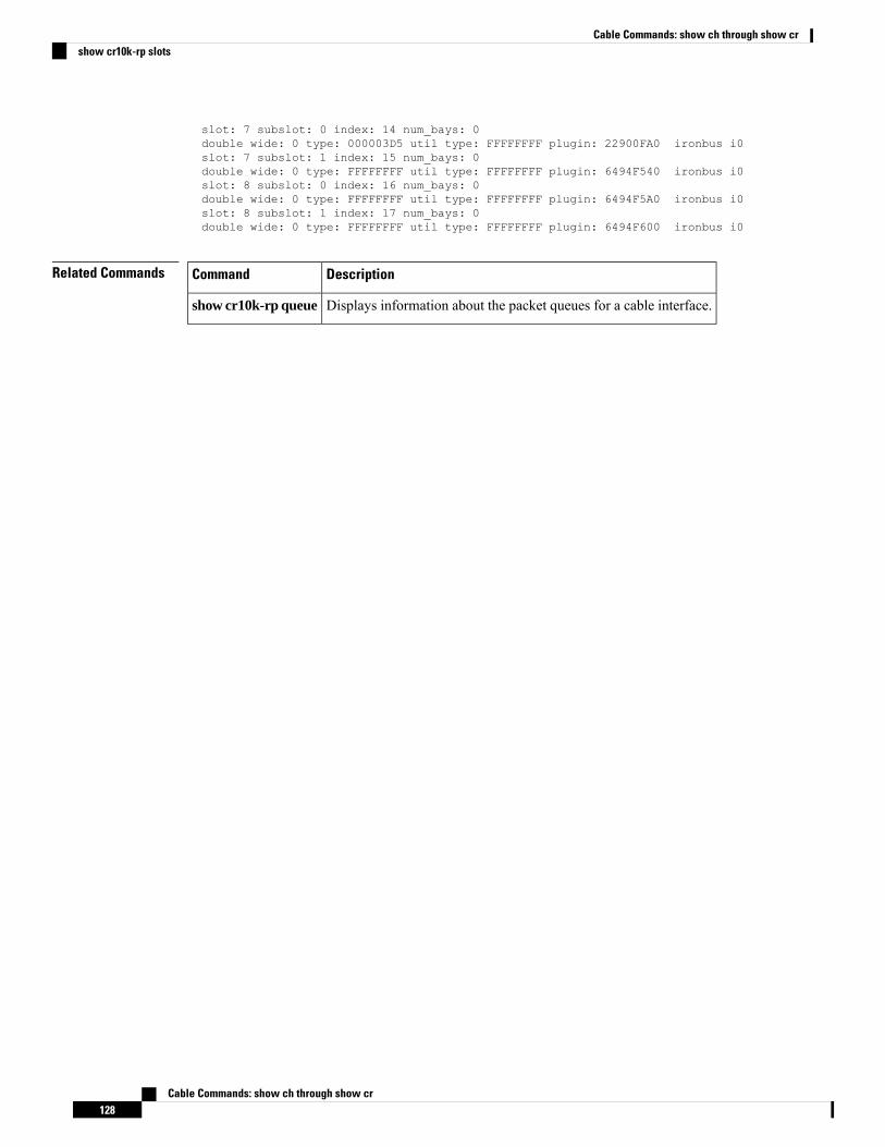
slot: 7 subslot: 0 index: 14 num_bays: 0double wide: 0 type: 000003D5 util type: FFFFFFFF plugin: 22900FA0 ironbus i0slot: 7 subslot: 1 index: 15 num_bays: 0double wide: 0 type: FFFFFFFF util type: FFFFFFFF plugin: 6494F540 ironbus i0slot: 8 subslot: 0 index: 16 num_bays: 0double wide: 0 type: FFFFFFFF util type: FFFFFFFF plugin: 6494F5A0 ironbus i0slot: 8 subslot: 1 index: 17 num_bays: 0double wide: 0 type: FFFFFFFF util type: FFFFFFFF plugin: 6494F600 ironbus i0
Related Commands DescriptionCommand
Displays information about the packet queues for a cable interface.show cr10k-rp queue
Cable Commands: show ch through show cr128
Cable Commands: show ch through show crshow cr10k-rp slots


![Msg 016[1]](https://img.pdfslide.us/doc/110x75/55b1fa7bbb61eb807f8b45a7/msg-0161.jpg)
