Embed Size (px)
Citation preview
Programming Guide Release 5.3
CA TPX™ Session Management
This Documentation, which includes embedded help systems and electronically distributed materials, (hereinafter referred to as the “Documentation”) is for your informational purposes only and is subject to change or withdrawal by CA at any time. This Documentation is proprietary information of CA and may not be copied, transferred, reproduced, disclosed, modified or duplicated, in whole or in part, without the prior written consent of CA.
If you are a licensed user of the software product(s) addressed in the Documentation, you may print or otherwise make available a reasonable number of copies of the Documentation for internal use by you and your employees in connection with that software, provided that all CA copyright notices and legends are affixed to each reproduced copy.
The right to print or otherwise make available copies of the Documentation is limited to the period during which the applicable license for such software remains in full force and effect. Should the license terminate for any reason, it is your responsibility to certify in writing to CA that all copies and partial copies of the Documentation have been returned to CA or destroyed.
TO THE EXTENT PERMITTED BY APPLICABLE LAW, CA PROVIDES THIS DOCUMENTATION “AS IS” WITHOUT WARRANTY OF ANY KIND, INCLUDING WITHOUT LIMITATION, ANY IMPLIED WARRANTIES OF MERCHANTABILITY, FITNESS FOR A PARTICULAR PURPOSE, OR NONINFRINGEMENT. IN NO EVENT WILL CA BE LIABLE TO YOU OR ANY THIRD PARTY FOR ANY LOSS OR DAMAGE, DIRECT OR INDIRECT, FROM THE USE OF THIS DOCUMENTATION, INCLUDING WITHOUT LIMITATION, LOST PROFITS, LOST INVESTMENT, BUSINESS INTERRUPTION, GOODWILL, OR LOST DATA, EVEN IF CA IS EXPRESSLY ADVISED IN ADVANCE OF THE POSSIBILITY OF SUCH LOSS OR DAMAGE.
The use of any software product referenced in the Documentation is governed by the applicable license agreement and such license agreement is not modified in any way by the terms of this notice.
The manufacturer of this Documentation is CA.
Provided with “Restricted Rights.” Use, duplication or disclosure by the United States Government is subject to the restrictions set forth in FAR Sections 12.212, 52.227-14, and 52.227-19(c)(1) - (2) and DFARS Section 252.227-7014(b)(3), as applicable, or their successors.
Copyright © 2013 CA. All rights reserved. All trademarks, trade names, service marks, and logos referenced herein belong to their respective companies.
CA Technologies Product References
This document references the following CA Technologies products:
■ CA TPX™ Session Management (CA TPX)
■ CA STX™ (CA STX)
■ CA ACF2® Security (CA ACF2)
■ CA Top Secret® Security (CA Top Secret)
■ CA IDMS™ Database (CA IDMS Database)
■ CA IDMS™/DC Database (CA IDMS/DC Database)
■ CA 7®Job Management (CA 7)
■ CA Remote Console™ (CA Remote)
■ CA TCPaccess™ Telnet Server (CA TCPaccess Telnet Server)
■ CA Vman™ (CA Vman)
Contact CA Technologies
Contact CA Support
For your convenience, CA Technologies provides one site where you can access the information that you need for your Home Office, Small Business, and Enterprise CA Technologies products. At http://ca.com/support, you can access the following resources:
■ Online and telephone contact information for technical assistance and customer services
■ Information about user communities and forums
■ Product and documentation downloads
■ CA Support policies and guidelines
■ Other helpful resources appropriate for your product
Providing Feedback About Product Documentation
If you have comments or questions about CA Technologies product documentation, you can send a message to [email protected].
To provide feedback about CA Technologies product documentation, complete our short customer survey which is available on the CA Support website at http://ca.com/docs.
Contents 5
Contents
Chapter 1: Customizing CA TPX 17
About CA TPX ............................................................................................................................................................. 17
More Information about Customization Tasks .......................................................................................................... 17
Modify Panels ...................................................................................................................................................... 17
Special Features and Customization Tasks .......................................................................................................... 18
Customize Tasks for Certain Applications ........................................................................................................... 19
User Exits ............................................................................................................................................................. 20
Chapter 2: Modifying Panels 21
Language Identifiers ................................................................................................................................................... 21
Use National Character Set Devices ........................................................................................................................... 22
Modifying a Panel ....................................................................................................................................................... 22
Modify One-Line Messages ................................................................................................................................. 23
Rules and Guidelines ........................................................................................................................................... 23
Create Panels.............................................................................................................................................................. 23
Sections of a Panel Definition .................................................................................................................................... 23
Attribute .............................................................................................................................................................. 23
Body .................................................................................................................................................................... 24
Model .................................................................................................................................................................. 24
Resume................................................................................................................................................................ 24
Initialization ......................................................................................................................................................... 24
End ...................................................................................................................................................................... 24
Rules Governing Panel Definitions ............................................................................................................................. 24
Required Sections ............................................................................................................................................... 25
Order of Sections ................................................................................................................................................ 25
Control Statements ............................................................................................................................................. 25
Comments ........................................................................................................................................................... 25
Number of Lines and Statements ........................................................................................................................ 25
Attribute Section ........................................................................................................................................................ 26
Sample Attribute Section .................................................................................................................................... 26
Characters ........................................................................................................................................................... 26
Comments ........................................................................................................................................................... 27
Attribute Keywords and Values .......................................................................................................................... 27
Body Section ............................................................................................................................................................... 30
Sample Body Section ........................................................................................................................................... 30
Items You Should Not Remove ........................................................................................................................... 30
6 Programming Guide
MODEL and RESUME Statements............................................................................................................................... 31
Example of a Scrollable Area ............................................................................................................................... 31
Initialization Section ................................................................................................................................................... 32
Specify Substitution Variable Names .................................................................................................................. 32
Specify Help Panel Names ................................................................................................................................... 32
End Section ................................................................................................................................................................. 33
Date Variables in Panels ............................................................................................................................................. 33
Changing the Date Format .................................................................................................................................. 34
View Facility Panels ............................................................................................................................................. 34
Date Variables ..................................................................................................................................................... 35
Mail Facility Variables ......................................................................................................................................... 35
Z$DATE and Z$UDATE ......................................................................................................................................... 36
TEN0003 – User Signon Panel for Traditional Password Verification ................................................................. 37
TEN1003 – User Signon Panel for Password Phrase/Password Verification ....................................................... 41
Chapter 3: Special Features and Customization Tasks 45
TCPaccess Telnet Server Interface ............................................................................................................................. 45
Activate the Interface ......................................................................................................................................... 45
Important Notes .................................................................................................................................................. 46
Affinity Feature .......................................................................................................................................................... 46
How the /F Command Works .............................................................................................................................. 46
Turning the Affinity Field On ............................................................................................................................... 46
Establish Affinity for a User ................................................................................................................................. 47
Establish Affinity with a User Exit ....................................................................................................................... 47
Propagate Password Changes ............................................................................................................................. 47
Establish Affinity Between Systems .................................................................................................................... 47
Pass Ticket Feature ..................................................................................................................................................... 48
Qualified and Nonqualified Pass Tickets ............................................................................................................. 49
Requirements for Pass Ticket .............................................................................................................................. 49
How Pass Ticket Works ....................................................................................................................................... 50
Pass Ticket Use with CA TPX Functions ............................................................................................................... 50
Operational Difference for Pass Ticket Users...................................................................................................... 51
Pass Ticket Reconnections .................................................................................................................................. 51
&PSWD Variable Becomes Unusable .................................................................................................................. 51
Consequences of an Invalid &PSWD Variable ..................................................................................................... 51
Send the User's Real Password to an Application ............................................................................................... 52
Maintenance for Pass Ticket—An Overview ....................................................................................................... 52
Screens and Field for Pass Ticket Maintenance .................................................................................................. 53
Field Definitions .................................................................................................................................................. 54
Configuration ...................................................................................................................................................... 56
Related Publications ............................................................................................................................................ 56
Contents 7
Specify Access Modes ................................................................................................................................................ 56
How to Customize Security ........................................................................................................................................ 57
Customize Security When Security System Is SAF .............................................................................................. 57
Customize Security When Security System Is RACF ............................................................................................ 58
Customize Security When Security System Is CA Top Secret .............................................................................. 59
Customize Security When Security System Is CA ACF2 ....................................................................................... 59
Customize Security When Security System Is CA TPX Security ........................................................................... 60
Customize Security When Security System Is User Exit Security ........................................................................ 60
Use CA TPX Security to Access CA STX ................................................................................................................ 60
Enhanced Security Process.................................................................................................................................. 61
Additional Security Options........................................................................................................................................ 61
Use User Names from the Security System ........................................................................................................ 62
Bypass New Password Verification ..................................................................................................................... 62
Security Action/Message Table ........................................................................................................................... 62
Use External Security to Determine Applications on TPX Menu ......................................................................... 63
Profile Selection for Dynamic Users .................................................................................................................... 64
Suppress the Logo Panel ..................................................................................................................................... 64
Profile Selection for Dynamic Users ........................................................................................................................... 64
Methods of Profile Selection ............................................................................................................................... 65
How to Set Up User-level Profile Selection ......................................................................................................... 65
How to Set Up Profile-level Profile Selection ...................................................................................................... 67
Customize the APTPX Member .................................................................................................................................. 68
Use VTAM Modeling in VTAMLST Member ........................................................................................................ 69
Application Definition Statements ...................................................................................................................... 69
MAXAPPL Parameter ........................................................................................................................................... 69
Sample Statements ............................................................................................................................................. 69
Description of Statements .................................................................................................................................. 71
Application Definition Parameters ...................................................................................................................... 72
Customize Logon Mode Tables .................................................................................................................................. 74
Applications with Predefined Terminal Definition .............................................................................................. 75
Applications Requiring Logmode Entries with Special Names ............................................................................ 75
Force CA TPX to Use a Particular Mode Table ..................................................................................................... 76
Adjust Storage Parameter .......................................................................................................................................... 76
Specify Storage Options ...................................................................................................................................... 76
How CA TPX Responds to Storage Requests ....................................................................................................... 77
Display Storage Statistics .................................................................................................................................... 77
Example of Storage Statistics .............................................................................................................................. 78
Field Descriptions for Storage Statistics .............................................................................................................. 78
Adjust Slot Pool Storage ...................................................................................................................................... 80
Interpret and Adjust DSA Storage ....................................................................................................................... 81
Increase Overall Storage ..................................................................................................................................... 81
Slot Pool Storage and Analysis Reports ...................................................................................................................... 81

8 Programming Guide
Create Reports .................................................................................................................................................... 82
Storage Slot Pool Summary ................................................................................................................................. 82
Slot Pool Usage—Mean....................................................................................................................................... 83
Slot Pool Usage ................................................................................................................................................... 83
Storage Allocation ............................................................................................................................................... 84
Mail Facility ................................................................................................................................................................ 84
Command Authorization ..................................................................................................................................... 85
Userlists ............................................................................................................................................................... 85
Mail Functions with the Batch Facility ................................................................................................................ 86
Mail Locators ....................................................................................................................................................... 86
View Facility ............................................................................................................................................................... 86
View Facility Security .......................................................................................................................................... 86
View Is an Authorized Feature ............................................................................................................................ 87
Control Application Sessions with OPENGATE ........................................................................................................... 87
Example ............................................................................................................................................................... 87
Setting Up OPENGATE ......................................................................................................................................... 87
Create Control ACL/E Programs .......................................................................................................................... 88
Variables Used in ................................................................................................................................................. 88
Error Messages .................................................................................................................................................... 89
Build Control Users ............................................................................................................................................. 90
Update ACT ......................................................................................................................................................... 91
Advanced Data Compression ..................................................................................................................................... 91
Inbound Data Compression................................................................................................................................. 91
Outbound Data Compression .............................................................................................................................. 92
Function of Outbound Stripping ......................................................................................................................... 92
Turning on Compression ..................................................................................................................................... 92
Turning on Outbound Stripping .......................................................................................................................... 93
Display Compression Statistics ............................................................................................................................ 93
Implement Tiered Menus ........................................................................................................................................... 93
Example of a Tiered Menu Design ...................................................................................................................... 94
Explanation of Tiered Menu Design Example ..................................................................................................... 98
Chapter 4: Customizing for Certain Applications 107
Define Shared Applications ...................................................................................................................................... 107
Defining Group Applications .................................................................................................................................... 108
Special Considerations for Certain Applications ...................................................................................................... 108
Customize CICS Transaction Server .......................................................................................................................... 109
Create an Application Definition ....................................................................................................................... 109
Use the CICS RDO Feature ................................................................................................................................. 110
TERMINAL Definition ......................................................................................................................................... 110
TYPETERM Definition ........................................................................................................................................ 110

Contents 9
Use CICS Autoinstall .......................................................................................................................................... 111
Parameter Values .............................................................................................................................................. 112
LOGMODE Parameter ....................................................................................................................................... 112
Use Passthrough Printing .................................................................................................................................. 113
CICS RDO TERMINAL Parameters ...................................................................................................................... 113
CICS RDO TYPETERM Parameters ...................................................................................................................... 114
Customize HCF ......................................................................................................................................................... 116
Create an Application Definition ....................................................................................................................... 117
Logon Mode Tables ........................................................................................................................................... 117
DPCX .................................................................................................................................................................. 117
DPPX .................................................................................................................................................................. 118
Customize CAIDMS ................................................................................................................................................... 118
Create an Application Definition ....................................................................................................................... 119
Define Virtual Terminals ................................................................................................................................... 119
Customize IMS .......................................................................................................................................................... 119
Creating an Application Definition .................................................................................................................... 120
Sample of IMSGEN Statements ......................................................................................................................... 120
Description of IMSGEN Statements .................................................................................................................. 121
Representation of Real Terminal to IMS ........................................................................................................... 123
User Passthrough Printing ................................................................................................................................. 123
Customize the IBM Information Network ................................................................................................................ 124
Create an Application Definition ....................................................................................................................... 124
SIMLOGON ........................................................................................................................................................ 124
User Passthrough Printing ................................................................................................................................. 124
Customize Netview/NCCF ........................................................................................................................................ 125
Create an Application Definition ....................................................................................................................... 125
Tailor Netview/NCCF for CA TPX ....................................................................................................................... 125
Customize NetSpy .................................................................................................................................................... 125
Create an Application Definition ....................................................................................................................... 126
Define CA TPX to NetSpy ................................................................................................................................... 126
Customize TCAM ...................................................................................................................................................... 126
Terminal Definitions .......................................................................................................................................... 126
Customize TSO ......................................................................................................................................................... 126
Create an Application Definition ....................................................................................................................... 126
Example of a TSO Major Node .......................................................................................................................... 127
TSO Unique Name ............................................................................................................................................. 127
Graphics ............................................................................................................................................................ 127
TSO RECONNECT ............................................................................................................................................... 128
SessionData Field .............................................................................................................................................. 128
Customize VSPC ........................................................................................................................................................ 128
Create an Application Definition ....................................................................................................................... 128
10 Programming Guide
Chapter 5: Setting Up User Exits 129
Assemble the Exits ................................................................................................................................................... 131
Prerequisites ............................................................................................................................................................ 131
System Options Table (SMRT) Values ...................................................................................................................... 131
How to Access SMRT Values ............................................................................................................................. 131
31-bit Addressing Mode ........................................................................................................................................... 131
How the Operating System Is Determined ....................................................................................................... 132
Generate Trace Entries ............................................................................................................................................. 132
Reentrant Programs ................................................................................................................................................. 132
If You Do Not Want a Work Area ...................................................................................................................... 132
To Acquire a Work Area .................................................................................................................................... 132
Boundary Alignment ................................................................................................................................................ 133
Communicate with a User from an Exit Routine ...................................................................................................... 133
Macro for Displaying a Panel ............................................................................................................................ 133
Parameters for Displaying a Panel .................................................................................................................... 133
Sample TPXDSPL Macro .................................................................................................................................... 134
Macros for Working with Variables .................................................................................................................. 134
Parameters for Working with Variables ............................................................................................................ 136
Issue a Command from an Exit Routine ................................................................................................................... 136
Variable Descriptions ........................................................................................................................................ 137
ACB Selection Exit..................................................................................................................................................... 137
Program and Link the Exit ................................................................................................................................. 137
Register Contents .............................................................................................................................................. 137
Entry Codes ....................................................................................................................................................... 138
Parameter List ................................................................................................................................................... 138
Return Codes ..................................................................................................................................................... 139
ACL Parameter Exit ................................................................................................................................................... 139
Program and Link the Exit ................................................................................................................................. 139
Entry Codes ....................................................................................................................................................... 139
Parameter List ................................................................................................................................................... 140
Return Codes ..................................................................................................................................................... 140
Command Exit .......................................................................................................................................................... 141
Where the Exit is Called .................................................................................................................................... 141
Program and Link Exit ....................................................................................................................................... 141
Register Contents .............................................................................................................................................. 141
Parameter List ................................................................................................................................................... 142
Return Codes ..................................................................................................................................................... 142
Command Simulation Exit ........................................................................................................................................ 144
Program and Link the Exit ................................................................................................................................. 144
Entry Codes ....................................................................................................................................................... 144
Parameter List ................................................................................................................................................... 144
Contents 11
Return Codes ..................................................................................................................................................... 145
Contents of Control Blocks ................................................................................................................................ 145
Encrypt/Decrypt Exit ................................................................................................................................................ 145
Program and Link the Exit ................................................................................................................................. 145
Register Contents .............................................................................................................................................. 146
Error Processing Exit................................................................................................................................................. 146
Program and Link the Exit ................................................................................................................................. 146
Register Contents .............................................................................................................................................. 146
Parameter List ................................................................................................................................................... 147
Action Indicator Bits .......................................................................................................................................... 147
LOG Writer Exit ......................................................................................................................................................... 147
Program and Link the Exit ................................................................................................................................. 147
TPX--LOG Writer Exit--Register Contents .......................................................................................................... 148
Return Codes ..................................................................................................................................................... 148
Logon Exit ................................................................................................................................................................. 148
Program and Link the Exit ................................................................................................................................. 148
Register Contents .............................................................................................................................................. 149
Parameter List ................................................................................................................................................... 149
Return Codes ..................................................................................................................................................... 150
Option Field Values ........................................................................................................................................... 150
Logo Name ........................................................................................................................................................ 150
Attention Interval .............................................................................................................................................. 150
Terminal Options Table ..................................................................................................................................... 151
Mail Exit .................................................................................................................................................................... 151
Program and Link the Exit ................................................................................................................................. 151
Call Points .......................................................................................................................................................... 151
Parameters ........................................................................................................................................................ 152
Call Point Masking Table for Parameter +16 ..................................................................................................... 152
Return Codes ..................................................................................................................................................... 153
Variables ............................................................................................................................................................ 153
Macros for Table Variables ............................................................................................................................... 158
Route Mail Through External Means ................................................................................................................ 158
Menu Exit ................................................................................................................................................................. 158
Program and Link the Exit ................................................................................................................................. 158
Register Contents .............................................................................................................................................. 159
Parameter List ................................................................................................................................................... 159
Return Codes ..................................................................................................................................................... 160
ZCMD Field ........................................................................................................................................................ 160
Print Banner Exit....................................................................................................................................................... 160
Program and Link the Exit ................................................................................................................................. 161
Register Contents .............................................................................................................................................. 161
Parameter List ................................................................................................................................................... 161
12 Programming Guide
Return Codes ..................................................................................................................................................... 162
Location of Banner in Storage ........................................................................................................................... 162
VTAM Printers ................................................................................................................................................... 162
JES Banners ....................................................................................................................................................... 162
Printer Selection Exit ................................................................................................................................................ 163
Program and Link the Exit ................................................................................................................................. 163
Register Contents .............................................................................................................................................. 163
Parameter List for the PPS Call Point ................................................................................................................ 163
Return Codes for the PPS Call Point .................................................................................................................. 164
Parameter List for the /P Call Point................................................................................................................... 164
Return Codes for the /P Call Point .................................................................................................................... 164
Query Response Exit ................................................................................................................................................ 164
Program and Link the Exit ................................................................................................................................. 165
Register Contents .............................................................................................................................................. 165
Parameter List ................................................................................................................................................... 165
Return Codes ..................................................................................................................................................... 166
Queue Exit ................................................................................................................................................................ 166
Program and Link the Exit ................................................................................................................................. 166
Register Contents .............................................................................................................................................. 166
Parameter List ................................................................................................................................................... 167
Return Codes ..................................................................................................................................................... 168
Route Screen Images ......................................................................................................................................... 168
Session Parameters ........................................................................................................................................... 168
Receive Exit .............................................................................................................................................................. 168
Program and Link the Exit ................................................................................................................................. 169
Register Contents .............................................................................................................................................. 169
Parameter List ................................................................................................................................................... 169
RPL Notes .......................................................................................................................................................... 169
Use This Exit with the Send Exit ........................................................................................................................ 170
Edit the Sample Exit .......................................................................................................................................... 170
Route Exit ................................................................................................................................................................. 170
Program and Link the Exit ................................................................................................................................. 170
Register Contents .............................................................................................................................................. 171
Parameter List ................................................................................................................................................... 171
Session List ........................................................................................................................................................ 171
Return Codes ..................................................................................................................................................... 172
Send Exit ................................................................................................................................................................... 173
Program and Link the Exit ................................................................................................................................. 173
Register Contents .............................................................................................................................................. 173
Parameter List ................................................................................................................................................... 173
RPL Notes .......................................................................................................................................................... 174
Translate or Reformat Output Data .................................................................................................................. 174
Contents 13
Use This Exit with the Receive Exit .................................................................................................................... 174
Session Initiation/Termination Exit .......................................................................................................................... 174
Program and Link the Exit ................................................................................................................................. 174
Register Contents .............................................................................................................................................. 175
Parameter Lists ................................................................................................................................................. 175
Return Codes ..................................................................................................................................................... 176
Signon and Signoff Exit ............................................................................................................................................. 176
Profiles for Dynamic Users ................................................................................................................................ 177
Program and Link the Exit ................................................................................................................................. 177
Register Contents .............................................................................................................................................. 177
Function Code, Parameters, and Return Codes ................................................................................................ 177
Parameter List ................................................................................................................................................... 182
General Notes About the Parameter List .......................................................................................................... 183
Parameters Passed for Specific Function Calls .................................................................................................. 184
Parameters That Can Be Modified .................................................................................................................... 186
Multitasking ...................................................................................................................................................... 187
Signon Function ................................................................................................................................................. 187
Abend in ONOFF or the User Exit ...................................................................................................................... 187
Session Portability ............................................................................................................................................. 187
ADDPROF Macro ............................................................................................................................................... 188
Affinity Processing ............................................................................................................................................. 189
Switch-in Exit ............................................................................................................................................................ 189
Program and Link the Exit ................................................................................................................................. 189
Register Contents .............................................................................................................................................. 190
Parameter List ................................................................................................................................................... 190
Return Codes ..................................................................................................................................................... 191
Contents of Control Blocks ................................................................................................................................ 191
Timeout Option Override Exit .................................................................................................................................. 191
Program and Link the Exit ................................................................................................................................. 192
Register Contents .............................................................................................................................................. 192
Entry Codes ....................................................................................................................................................... 192
Parameter List ................................................................................................................................................... 193
Workarea Format .............................................................................................................................................. 193
View Security Access User Exit ................................................................................................................................. 194
Program and Link the Exit ................................................................................................................................. 194
Sample Exits ...................................................................................................................................................... 194
Register Contents .............................................................................................................................................. 195
Parameter List for Call Point X'00' ..................................................................................................................... 195
Return Codes for Call Point X'00' ...................................................................................................................... 195
Parameter List for Call Point X'04' ..................................................................................................................... 196
Return Codes for Call Point X'04' ...................................................................................................................... 196
Parameter List for Call Point X'08' ..................................................................................................................... 196

14 Programming Guide
Return Codes for Call Point X'08' ...................................................................................................................... 197
Parameters for Call Point X'12' ......................................................................................................................... 197
Return Codes for Call Point X'12' ...................................................................................................................... 198
Parameters for Call Point X'16' ......................................................................................................................... 198
Return Codes for Call Point X'16' ...................................................................................................................... 198
Parameters for Call Point X'20' ......................................................................................................................... 199
Return Codes for Call Point X'20' ...................................................................................................................... 199
Parameters for Call Point X'24' ......................................................................................................................... 199
Return Codes for Call Point X'24' ...................................................................................................................... 200
Parameters for Call Point X'28' ......................................................................................................................... 200
Return Codes for Call Point X'28' ...................................................................................................................... 200
Parameters for Call Point X'32', X'36' and X'40' ................................................................................................ 201
Return Codes for Call Point X'32', X'36' and X'40' ............................................................................................. 201
Parameters for Call Point X'44' ......................................................................................................................... 202
Return Codes for Call Point X'44' ...................................................................................................................... 202
Parameters for Call Point X'48' ......................................................................................................................... 203
Return Codes for Call Point X'48' ...................................................................................................................... 203
Parameters for Call Point X'52' ......................................................................................................................... 203
Return Codes for Call Point X'52' ...................................................................................................................... 204
Parameters for Call Point X'56' ......................................................................................................................... 204
Return Codes for Call Point X'56' ...................................................................................................................... 205
Parameters for Call Point X'60', X'64' and X'68' ................................................................................................ 205
Return Codes for Call Point X'60', X'64' and X'68' ............................................................................................. 206
Parameters for Call Point X'72' ......................................................................................................................... 206
Return Codes for Call Point X'72' ...................................................................................................................... 206
Chapter 6: Frequently Asked Questions 207
FAQs ......................................................................................................................................................................... 207
Chapter 7: Contacting Technical Support 213
Diagnostic Procedures .............................................................................................................................................. 214
Collect Diagnostic Data ..................................................................................................................................... 215
Interpret Diagnostic Data .................................................................................................................................. 215
CA-TLC: Total License Care ....................................................................................................................................... 216
Product Versions and Maintenance ......................................................................................................................... 216
Appendix A: SMF Records 217
Record Types ............................................................................................................................................................ 217
CA TPX CB0VMAC(MONSMF) ................................................................................................................................... 218

Contents 15
Appendix B: CAVman Conversion 231
Tape Contents .......................................................................................................................................................... 231
Load the Tape to Disk ........................................................................................................................................ 232
Run the CONVERT Job .............................................................................................................................................. 232
Items Not Converted ................................................................................................................................................ 233
Application Characteristics Table ............................................................................................................................. 233
Print Destination Table ............................................................................................................................................. 233
Profiles ..................................................................................................................................................................... 234
Users ......................................................................................................................................................................... 234
User Level Information ...................................................................................................................................... 234
Command Authority .......................................................................................................................................... 234
Session Level Information ................................................................................................................................. 235
Session Procedures .................................................................................................................................................. 235
Session Procedure Naming ............................................................................................................................... 235
SPL Procedures .................................................................................................................................................. 236
Procedure Parameters ...................................................................................................................................... 236
Job Task Logs ............................................................................................................................................................ 237
Index 239


Chapter 1: Customizing CA TPX 17
Chapter 1: Customizing CA TPX
This section contains the following topics:
About CA TPX (see page 17) More Information about Customization Tasks (see page 17)
About CA TPX
CA TPX is a session manager for users of 3270-type terminals on a VTAM network. To these end users, the product offers a consistent, secure entry point into the system each day. Any user who signs on through this product can have simultaneous access to more than one application at a time and quickly toggle from one session to another by pressing one key. The name TPX is an acronym for Terminal Productivity Executive.
More Information about Customization Tasks
The customization tasks explained in this guide are provided to help you make the product run more effectively and best suit the needs of the users at your site. This guide shows you how to perform such tasks as:
■ Modifying panels
■ Customizing CA TPX and the applications you use with it
■ Implementing the user exits
Modify Panels
You can modify the appearance, content, and other attributes of any panel by editing its panel definition. You can modify the panels to provide an alternate appearance or additional online help. You can also provide system news or online help for applications by creating your own panels and displaying them with an ACL/E program. For information about writing an ACL/E program that displays customized panels, see the ACL/E Programmer Guide.

More Information about Customization Tasks
18 Programming Guide
Special Features and Customization Tasks
You can customize the product to provide additional functionality at your site. The following is a list of these special customization tasks:
Using the Affinity Feature
This feature allows you to pass control of a user's sessions from one system to another. You should use this feature when you run the product on more than one host.
Using the Pass Ticket Feature
You can eliminate the need for users to manually type their password on the TPX logon screen, as well as eliminate the transmittal of the same password in clear text across networks. A pass ticket provides application security, since it is a one-time only password with a limited life span.
Specifying Access Modes
You can specify access modes to determine how and when users can access application sessions.
Using the Product with Other Security Systems
When you are using a security system such as CA ACF2, CA Top Secret, or RACF, you must perform some additional customization tasks.
Customizing the APTPX Member
You need to customize the APTPX member to define the following:
■ CA TPX as a primary logical unit
■ Virtual terminals
■ Application and user pass-through printing
Customizing Logon Mode Tables
You need to customize the logon mode tables if you are using the product with CICS or other applications that are sensitive to terminal models.
Adjusting Storage Parameters
Because the product manages its own storage both above and below the 16-megabyte line, you can improve efficiency by specifying storage parameters.
Controlling Application Sessions with OPENGATE
You can use OPENGATE to perform the pre-session setup and post-session cleanup required for some application sessions.

More Information about Customization Tasks
Chapter 1: Customizing CA TPX 19
Customize Tasks for Certain Applications
You may need to perform some customization tasks if you are using the product with any of the following applications:
■ CA IDMS or CA IDMS/DC Database
■ CA Roscoe Interactive Environment
■ CICS Transaction Server
■ HCF
■ IIPS
■ IMS
■ IBM Information Network
■ NetView/NCCF
■ CA NetSpy Network Performance
■ Omegamon
■ Phoenix
■ RMDS
■ TCAM
■ TSO
■ CA 7
■ CA Remote Console
■ CA STX
■ VM/VCNA
■ VM/VSCS (VM/SNA native)
■ VSPC
More Information about Customization Tasks
20 Programming Guide
User Exits
You can use one of the user exits to provide the right environment for every end user.
When customizing TPX user exits, it is recommended that you create a site-specific version of the exit source and leave the original source in CB0VSRC sample library unchanged.
The customized exit should be assembled with the correct exit name and placed in a separate load library that is defined on the TPX proc '//STEPLIB DD' statement concatenated in front of the TPX product load library.
TPX will need to be cycled for new or modified exits to become active.
Chapter 2: Modifying Panels 21
Chapter 2: Modifying Panels
This chapter shows you how to modify the content, appearance, and other attributes of the CA TPX panels. You can modify the content, appearance, and other attributes of any panel by editing its panel definition. In the panel definition, you specify where each field on a panel begins and ends, what it contains, how it looks, and how users interact with it.
This section contains the following topics:
Language Identifiers (see page 21) Use National Character Set Devices (see page 22) Modifying a Panel (see page 22) Create Panels (see page 23) Sections of a Panel Definition (see page 23) Rules Governing Panel Definitions (see page 24) Attribute Section (see page 26) Body Section (see page 30) MODEL and RESUME Statements (see page 31) Initialization Section (see page 32) End Section (see page 33) Date Variables in Panels (see page 33)
Language Identifiers
Panel definitions for all languages are found in CB0VPxxx libraries, where xx is one of the following two-character language identifiers:
■ BF—Belgium French
■ BP—Brazilian Portuguese
■ CU—Systems Application Architecture CUA (Common User Access) compatible panels in English
■ DA—Danish
■ DU—Dutch
■ EN—English
■ FI—Finnish
■ FR—French
Use National Character Set Devices
22 Programming Guide
■ GE—German
■ IT—Italian
■ JP—Japanese
■ NO—Norwegian
■ SF—Swiss French
■ SG—Swiss German
■ SP—Spanish
■ SW—Swedish
■ UP—Upper Case English
If desired, you can change the status values on the Menu. These values are located in the TxxMSGL member, where xx is the language code.
Use National Character Set Devices
CA TPX uses standard EBCDIC character codes and does not recognize National Character Set character codes. If you are using a device that uses the National Character Set EBCDIC character codes, note that some special characters display differently.
For example, the variable VUSRPHN# appears as VUSRPHN¢ on a National Character Set device.
When customizing panels, be sure to use the correct character that the product recognizes. If you use the variable name as it appears on a National Character Set terminal or printer, this product may not recognize the variable. For a list of variable names, see the Batch Administration Guide.
Modifying a Panel
To modify an existing panel definition
1. Edit the panel definition using any editor.
2. Put the changes into effect by issuing the RELOAD command from an operator session, or use the Reload and Display option from the System Administration Menu. Use the following information to locate a panel definition:
■ Help panel definitions reside in members with names beginning with HEN. Those for other panels begin with TEN. (The H stands for Help, the T for CA TPX, and the EN for English.)
■ The name of the member containing a panel's definition appears in the upper-right corner of the panel.
Create Panels
Chapter 2: Modifying Panels 23
Modify One-Line Messages
TxxMSGL, where xx is the language code, contains one-line messages used by the product. You can modify these messages; the message prefix and number, however, must remain the same. Restart the product to put them into effect.
Rules and Guidelines
Follow the rules and guidelines described in the remaining sections of this chapter when modifying panels.
Create Panels
You can create panels and display them with an ACL/E program (for more information about ACL/E, see the ACL/E Programming Guide).
Keep the following in mind when creating your own panels:
■ Panel names beginning with T and H are reserved for use by CA TPX.
■ Panel names beginning with U will undergo language processing. If one of these panels is requested, the user's language code will replace the second and third characters in the panel name.
■ Panel names beginning with any other letter will not undergo language processing.
Follow the rules and guidelines described in the remaining sections of this chapter when creating panels.
Sections of a Panel Definition
Every panel definition contains at least four sections. Definitions for panels that have scrollable regions contain five or six sections, as described below.
Attribute
You define field characteristics in the attribute section. You also define the characters you want to use to assign the attributes to a field. There are no default attribute characters, so you must define your own. The attribute section starts with the ATTR statement and is terminated by a BODY statement. A panel definition must have an attribute section.

Rules Governing Panel Definitions
24 Programming Guide
Body
The body section defines what text will be displayed on the user's terminal screen. Each line of the body section defines one line on the displayed panel. You use the characters that you defined in the attribute section to define the characteristics of the fields in the body section. The body section starts with the BODY statement and is terminated by a MODEL or INIT statement. A panel definition must have a body section.
Model
On some panels, you want the user to be able to scroll through information that appears in the body section. You use a MODEL statement to indicate the beginning of a scrollable area of the panel. The MODEL section is terminated by a RESUME or INIT statement. The MODEL statement is optional.
Resume
You use the RESUME statement to indicate the end of a scrollable area that you defined with the MODEL statement. You need to use the RESUME statement only if there is non-scrollable text following the scrollable area. The RESUME statement is allowed only if you have a MODEL statement in your panel definition.
Initialization
You specify variable substitution names and help panel names in the initialization section. The initialization section starts with an INIT statement and ends with an END statement. A panel definition must have an initialization section.
End
The END statement indicates the end of the panel definition. Any data following the END statement is ignored. A panel definition must have an END statement.
Rules Governing Panel Definitions
You must adhere to the rules described in this section while creating or modifying panel descriptions.

Rules Governing Panel Definitions
Chapter 2: Modifying Panels 25
Required Sections
All panels must contain the attribute, body, initialization, and end sections. The model and resume sections are optional.
Order of Sections
The sections must appear in the following order:
1. Attribute
2. Body
3. Model
4. Resume
5. Initialization
6. End
Control Statements
Each section must begin with a control statement (ATTR, BODY, MODEL, RESUME, INIT, or END). You must precede a control statement with a right parenthesis ")" in column 1. For example, the control statement for the attribute section would look like this:
)ATTR
A section is terminated by the control statement that marks the beginning of the next section. For example, the BODY control statement indicates the end of the attribute section as well as the beginning of the body section.
You can enter control statements and text in uppercase or lowercase characters.
Comments
You can enter comments only in the attribute section or after the END statement.
Number of Lines and Statements
You cannot define more than a total of 24 data lines for the body, model, and resume sections.
The panel definition cannot contain more than 100 statements.
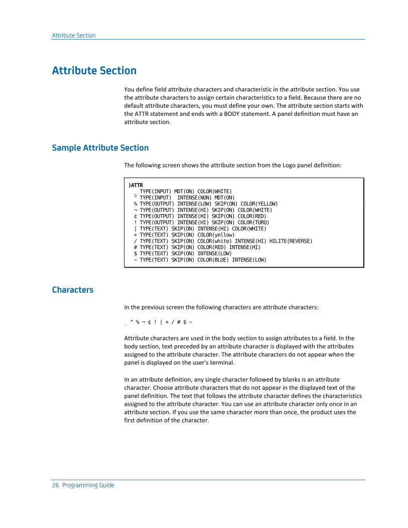
Attribute Section
26 Programming Guide
Attribute Section
You define field attribute characters and characteristic in the attribute section. You use the attribute characters to assign certain characteristics to a field. Because there are no default attribute characters, you must define your own. The attribute section starts with the ATTR statement and ends with a BODY statement. A panel definition must have an attribute section.
Sample Attribute Section
The following screen shows the attribute section from the Logo panel definition:
)ATTR _ TYPE(INPUT) MDT(ON) COLOR(WHITE) " TYPE(INPUT) INTENSE(NON) MDT(ON) % TYPE(OUTPUT) INTENSE(LOW) SKIP(ON) COLOR(YELLOW) ¬ TYPE(OUTPUT) INTENSE(HI) SKIP(ON) COLOR(WHITE) ¢ TYPE(OUTPUT) INTENSE(HI) SKIP(ON) COLOR(RED) ! TYPE(OUTPUT) INTENSE(HI) SKIP(ON) COLOR(TURQ) | TYPE(TEXT) SKIP(ON) INTENSE(HI) COLOR(WHITE) + TYPE(TEXT) SKIP(ON) COLOR(yellow) / TYPE(TEXT) SKIP(ON) COLOR(white) INTENSE(HI) HILITE(REVERSE) # TYPE(TEXT) SKIP(ON) COLOR(RED) INTENSE(HI) $ TYPE(TEXT) SKIP(ON) INTENSE(LOW) ~ TYPE(TEXT) SKIP(ON) COLOR(BLUE) INTENSE(LOW)
Characters
In the previous screen the following characters are attribute characters:
_ " % ¬ ¢ ! | + / # $ ~
Attribute characters are used in the body section to assign attributes to a field. In the body section, text preceded by an attribute character is displayed with the attributes assigned to the attribute character. The attribute characters do not appear when the panel is displayed on the user's terminal.
In an attribute definition, any single character followed by blanks is an attribute character. Choose attribute characters that do not appear in the displayed text of the panel definition. The text that follows the attribute character defines the characteristics assigned to the attribute character. You can use an attribute character only once in an attribute section. If you use the same character more than once, the product uses the first definition of the character.
Attribute Section
Chapter 2: Modifying Panels 27
Comments
You can put comments anywhere in the attribute section. Comments start with a slash followed by an asterisk (/*) and end with an asterisk followed by a slash (*/). Any data that is not a comment is considered to be part of an attribute definition.
Attribute Keywords and Values
Attributes consist of attribute keywords and attribute values. In the example, TYPE, SKIP, INTENSE, COLOR and MDT are attribute keywords. Attribute values follow keywords and are enclosed in parentheses. The following list describes the keywords and their possible values:
TYPE
The TYPE attribute indicates whether a field is protected or unprotected and whether it is of fixed or variable length. Protected fields cannot be modified. Unprotected fields can be modified. The TYPE attribute can have one of the following values:
TEXT
A text field is protected, so end users cannot modify data in a text field. Data in a text field is displayed on the panel exactly as it appears in the body of the panel definition. A variable name in a text field is replaced with the variable's current value. You must precede a variable name with an ampersand (&) and follow it with a space or period (.) to indicate that it is a variable name.
Text fields are of variable length.
OUTPUT
An output field is protected, so end users cannot modify data in an output field. An output field may contain only variable names in the panel definition. Unlike variable names in text fields, a variable name in an output field is not preceded by an ampersand.
When the panel is displayed, each variable name in the output field is replaced with the variable's current value.
Output fields are of fixed length.
INPUT
An input field is an unprotected field that can be modified by end users. An input field contains only a variable name in the panel definition. Unlike variable names in text fields, a variable name in an input field is not preceded by an ampersand.
When the user modifies the field on the displayed panel, the variable contains the value of the user's input.
Input fields are of fixed length.
Attribute Section
28 Programming Guide
NUM
You use the NUM (numeric) attribute with TYPE(INPUT) fields. If the NUM attribute has a value of ON, the user can enter only numeric input in the field. The keyboard locks if the user presses any key other than the following: 0 through 9, minus (-), duplicate (DUP), or period (.).
SKIP
The SKIP attribute indicates whether the cursor automatically bypasses a field when a user tabs through the panel. If the SKIP attribute has a value of ON, the cursor will bypass the field when the user moves through the panel using the TAB key (→). The skip feature can be used only for protected fields (TEXT or OUTPUT).
INTENSE
The INTENSE (intensity) attribute indicates the intensity or brightness of the field. Possible values are:
■ HI, which indicates high intensity.
■ LOW, which indicates low intensity.
■ NON, which indicates that the field is not displayed.
COLOR
The COLOR attribute indicates the color used to display the field. Colors appear only when the panel is displayed on a 3179, 3279-B, or 3192-type terminal. Possible values include:
■ RED
■ BLUE
■ GREEN
■ TURQ (turquoise)
■ PINK
■ YELLOW
■ WHITE
Note: When a panel that doesn't have color specified is displayed on a color terminal, a default color is generated for each field on the basis of the field's type and intensity:
■ High intensity text or output is white.
■ Low intensity text or output is blue.
■ High intensity input is red.
■ Low intensity input is green.
Attribute Section
Chapter 2: Modifying Panels 29
OUTLINE
The OUTLINE attribute specifies one of the available outline features:
■ L indicates a line to the left of the field.
■ R indicates a line to the right of the field.
■ O indicates a line over the field.
■ U indicates a line under the field.
■ BOX indicates a box around the field.
HILITE
The HILITE (highlight) attribute indicates the extended highlighting characteristics of the field. Possible values are:
■ REVERSE indicates reverse video.
■ BLINK indicates a blinking field.
■ USCORE indicates an underscored field.
Note: When a panel with the HILITE attribute is displayed on a terminal that does not support extended highlighting, the result depends on the following conditions:
■ If you have used the INTENSE attribute, the highlighting specification is ignored.
■ If you have not used the INTENSE attribute, a field with the HILITE attribute is displayed with high intensity.
MDT
The MDT (Modified Data Tag) attribute indicates whether the field should have the modified data tag present before being sent to the terminal.
FORMAT
The FORMAT attribute indicates the character format for double-byte character set (DBCS) terminals. Possible values are:
■ EBCDIC indicates EBCDIC characters only.
■ DBCS indicates double-byte characters only.
■ MIX indicates both double-byte and EBCDIC characters.
Note: In MIX mode, any double-byte character string must be enclosed by a shift-out (hexadecimal 0E) and a shift-in (hexadecimal 0F).
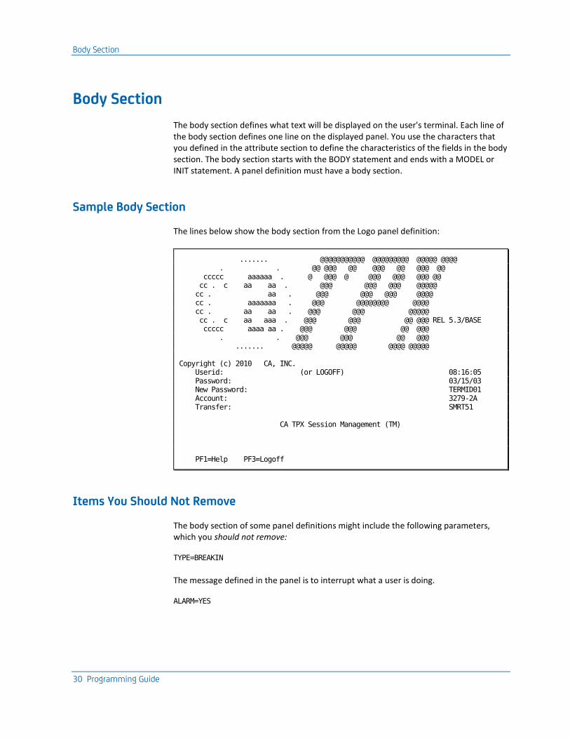
Body Section
30 Programming Guide
Body Section
The body section defines what text will be displayed on the user's terminal. Each line of the body section defines one line on the displayed panel. You use the characters that you defined in the attribute section to define the characteristics of the fields in the body section. The body section starts with the BODY statement and ends with a MODEL or INIT statement. A panel definition must have a body section.
Sample Body Section
The lines below show the body section from the Logo panel definition:
....... @@@@@@@@@@@ @@@@@@@@@ @@@@@ @@@@ . . @@ @@@ @@ @@@ @@ @@@ @@ ccccc aaaaaa . @ @@@ @ @@@ @@@ @@@ @@ cc . c aa aa . @@@ @@@ @@@ @@@@@ cc . aa . @@@ @@@ @@@ @@@@ cc . aaaaaaa . @@@ @@@@@@@@ @@@@ cc . aa aa . @@@ @@@ @@@@@ cc . c aa aaa . @@@ @@@ @@ @@@ REL 5.3/BASE ccccc aaaa aa . @@@ @@@ @@ @@@ . . @@@ @@@ @@ @@@ ....... @@@@@ @@@@@ @@@@ @@@@@ Copyright (c) 2010 CA, INC. Userid: (or LOGOFF) 08:16:05 Password: 03/15/03 New Password: TERMID01 Account: 3279-2A Transfer: SMRT51 CA TPX Session Management (TM) PF1=Help PF3=Logoff
Items You Should Not Remove
The body section of some panel definitions might include the following parameters, which you should not remove:
TYPE=BREAKIN
The message defined in the panel is to interrupt what a user is doing.
ALARM=YES

MODEL and RESUME Statements
Chapter 2: Modifying Panels 31
The message is to sound an audible alarm at the user's terminal.
Do not remove the CA copyright statement from the panel definition.
MODEL and RESUME Statements
On some panels, you want the user to be able to scroll through information that appears in the body section. You use a MODEL statement to indicate the beginning of a scrollable area of the panel. You terminate the MODEL section with a RESUME or INIT statement. You need to use the RESUME statement only if there is non-scrollable text following the scrollable area. A RESUME statement is allowed only if you have a MODEL statement. The MODEL statement is optional.
You can use only one data statement after the MODEL statement. This data statement is used as a model to construct each row of a table of data.
Example of a Scrollable Area
The following screen shows the body section of the Menu, which contains a scrollable area. The MODEL statement starts the area where the user's sessions are displayed, and the RESUME statement resumes the body section so that the command line and PF key definitions can be displayed.
)BODY TYPE=BREAKIN % &XPTNAME MENU FOR|zuserid +Panelid -?ZPANEL ¬ZHELP +Terminal -?ZTERMID + Cmdkey=&uidxesck+ Jump=&uidxjkey+Menu=&uidxmkey+ +Model -?TBMODEL + Print=&uidxpkey+ Cmdchar=&uidxchar+ +System -?W1 ¬W2 % % *Sessid% *Sesskey% *Session Description% *Status% % )MODEL _Z:uentuser; PF:Z + <Z ¬z + )RESUME %Command ===>_Zcmd + ¬w3 + +PF1=Help PF7/19=Up PF8/20=Down PF10/22=Left PF11/23=Right %H+=Cmd Help )INIT .ZVARS=(UENTSLCT UENTPJMP UENTLAB UENTWSTS) .HELP=(HEN0041) )END
Important! Do not move or change the first character (underscore) of the MODEL line on the Menu. If you do, the menu will not display properly.
Initialization Section
32 Programming Guide
Initialization Section
You specify variable substitution names and help panel names in the initialization section. The initialization section starts with an INIT statement and terminates with an END statement. A panel definition must have an initialization section.
Specify Substitution Variable Names
When you specify a variable name in a panel definition, the number of characters in the variable name is reserved for the value of that variable. Sometimes, however, you don't want that many character positions reserved for the variable. For example, you only need a six-character field to display a user's stage 1 timeout, and a two-character field to display a user's stage 1 timeout option. But the variable names (UIDXTOU1 and UIDXTOP1) are eight characters long.
To solve this problem, you enter a placeholder variable (the letter Z) in place of the actual variable name. For example, if the plus sign (+) and the number sign (#) are attribute characters, you might have the following data lines in the body section of a panel definition:
+Stage 1 Timeout: #Z +
+Stage 1 Option: #Z +
The letter Z itself takes up one space. Spaces between the Z and the plus sign (+) at the end of the line define the remaining character positions to give you a six-character field for the stage 1 timeout and a two-character field for the stage 1 option.
Now that you have defined the placeholder variables, you must use the .ZVARS parameter in the initialization section so that the software knows what to put in their place when the panel is displayed. The initialization section would look like this:
)INIT
.ZVARS=(UIDXTOU1 UIDXTOP1)
When you specify substitution variables in the initialization section, CA TPX substitutes the value of the first variable in place of the first Z placeholder it finds, the value of the second variable in place of the second Z placeholder, and so on.
Specify Help Panel Names
When a user presses the PF1 key, a one-line help message sometimes appears at the top of the panel. If the user presses PF1 again, or if a one-line message is not defined for the panel, the product displays a help panel.
End Section
Chapter 2: Modifying Panels 33
You can use the .HELP parameter in the initialization section to tell CA TPX what help messages and panels to display, and when to display them. For example, a panel definition contains the following initialization section:
)INIT
.HELP=(HEN0123 VAR1:HEN0123A VAR2:HEN0123A VAR3:HEN0123B)
The product uses the following process to determine what help messages and panels to display:
1. CA TPX finds the current location of the cursor on the screen. If the cursor is not in an input or output field, it uses the global help ID, which in this case is HEN0123. If the cursor is in an input or output field (for example, VAR2), it uses the help ID associated with that field. In this case, the help ID for VAR2 is HEN0123A.
2. CA TPX looks for the message ID in member TxxMSGL (where xx is the user's language code). This data set contains the line help messages. The first eight characters of the help messages are the message ID. If the software finds a message ID that matches the help ID, it displays the message on the line of the panel where the variable ZHELP is defined.
3. If there is no message ID matching the help ID, or if the user presses PF1 again, the software uses the help ID to find a member in the PANELS data set. If it finds a member name that matches the help ID, it displays the panel.
If it can't find a member name that matches the help ID, it uses the global help ID (in this case, HEN0123) and searches the PANELS data set again. If it can't find the global help ID in the data set, it displays the following message:
MEN0001 HELP not available
End Section
The END statement terminates the panel definition. Any data following the END statement is ignored. A panel definition must have an END statement.
Date Variables in Panels
You can control the formats of displayed dates. For example, you can control whether the date April 22, 2003 appears in English format, as follows:
04/22/03
or European format, as follows:
22/04/03
Date Variables in Panels
34 Programming Guide
Two things control the date format: the value of the "European dates" field, which is set in the operation parameters of the System Options Table (SMRT), and the actual variable used to display the date on the panel.
On most panels, you can change the variable to control the format of the date. However, you cannot change the variable in the View facility panels.
Changing the Date Format
To change the format of dates to European format (in all panels except those of the View facility):
So all panels will have European format dates
Set the European dates field to Y. You can cause a mixture of date formats when you change the value of this field. In table lists that are displayed in administration and user list maintenance, the update date shown for each table in the list appears in the format used when the table was last updated.
So some panels have European format dates
Set the European dates field to N and edit the specific panels to change the date variables. The available variables are listed in the section Date Variables.
View Facility Panels
The View facility panels are different. Do not attempt to edit the date variables in the View panels. Only the value of the European dates field determines the format of the date on these panels:
Value Date Format
Y Regardless of the language of the panels, the dates will appear in the format dd/mm/yy.
N Panels in the English and CUA libraries will have dates appearing in the format mm/dd/yy.
Panels in the other panel libraries will have dates appearing in the format dd/mm/yy.
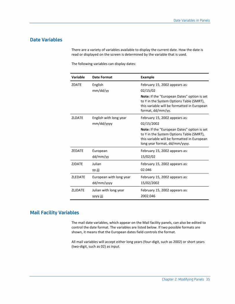
Date Variables in Panels
Chapter 2: Modifying Panels 35
Date Variables
There are a variety of variables available to display the current date. How the date is read or displayed on the screen is determined by the variable that is used.
The following variables can display dates:
Variable Date Format Example
ZDATE English
mm/dd/yy
February 15, 2002 appears as:
02/15/02
Note: If the "European Dates" option is set to Y in the System Options Table (SMRT), this variable will be formatted in European format, dd/mm/yy.
ZLDATE English with long year
mm/dd/yyyy
February 15, 2002 appears as:
02/15/2002
Note: If the "European Dates" option is set to Y in the System Options Table (SMRT), this variable will be formatted in European long year format, dd/mm/yyyy.
ZEDATE European
dd/mm/yy
February 15, 2002 appears as:
15/02/02
ZJDATE Julian
yy.jjj
February 15, 2002 appears as:
02.046
ZLEDATE European with long year
dd/mm/yyyy
February 15, 2002 appears as:
15/02/2002
ZLJDATE Julian with long year
yyyy.jjj
February 15, 2002 appears as:
2002.046
Mail Facility Variables
The mail date variables, which appear on the Mail facility panels, can also be edited to control the date format. The variables are listed below. If two possible formats are shown, it means that the European dates field controls the format.
All mail variables will accept either long years (four-digit, such as 2002) or short years (two-digit, such as 02) as input.

Date Variables in Panels
36 Programming Guide
For a description of the mail variables, see the Batch Administration Guide.
Variable Format
MLOCDATE mm/dd/yy or dd/mm/yy
MLOCDATF dd/mm/yy
MLOCDATL mm/dd/yyyy or dd/mm/yyyy
MLOCDATQ dd/mm/yyyy
MLOCEXPD mm/dd/yy or dd/mm/yy
MLOCEXPF mm/dd/yy
MLOCEXPL mm/dd/yyyy or dd/mm/yyyy
MLOCEXPQ dd/mm/yyyy
MMSGDATE mm/dd/yy or dd/mm/yy
MMSGDATF dd/mm/yy
MMSGDATL mm/dd/yyyy or dd/mm/yyyy
MMSGDATQ dd/mm/yyyy
MMSGEXPD mm/dd/yy or dd/mm/yy
MMSGEXPF mm/dd/yy
MMSGEXPL mm/dd/yyyy or dd/mm/yyyy
MMSGEXPQ dd/mm/yyyy
Z$DATE and Z$UDATE
Two variables, Z$DATE and Z$UDATE are available to display strings that indicate to users how the date is to be formatted. The strings displayed by these variables depend on the value of the European dates field.
When the variable Z$DATE appears on a panel, and European dates is set to N, it displays the following text string:
mm/dd/yy
If European dates is set to Y, it displays the following text string:
dd/mm/yy
When the variable Z$UDATE appears on a panel, it displays the following text string:
MM/DD/YY
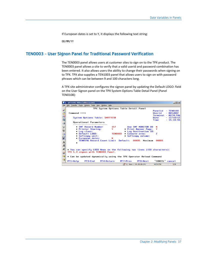
Date Variables in Panels
Chapter 2: Modifying Panels 37
If European dates is set to Y, it displays the following text string:
DD/MM/YY
TEN0003 – User Signon Panel for Traditional Password Verification
The TEN0003 panel allows users at customer sites to sign on to the TPX product. The TEN0003 panel allows a site to verify that a valid userid and password combination has been entered. It also allows users the ability to change their passwords when signing on to TPX. TPX also supplies a TEN1003 panel that allows users to sign on with password phrases which can be between 9 and 100 characters long.
A TPX site administrator configures the signon panel by updating the Default LOGO: field on the User Signon panel on the TPX System Options Table Detail Panel (Panel TEN0108):

Date Variables in Panels
38 Programming Guide
The sites can customize their TEN0003 Signon Panel. Perhaps a site wants to put their company name on their version of the TPX TEN0003 panel. There are many variables on the TEN0003 panel which will effects how the panel functions and what will be displayed.
The TEN0003 signon panel contains three very specific sign on related variables:
■ SNUSERV for a 1 to 8 character userid
■ SNPSWDV for a 1 to 8 character password
■ SNNPSWDV for a 0 to 8 character new password
Sites must be careful when modifying fields on the TEN0003 panel. The SNPSWDV and SNNPSWDV variable fields can contain up to 50 characters. Any time either the SNPSWDV or SNNPSWDV fields are entered with more than eight characters will cause the user to have a password phrase sign on attempt.
Source for TEN0003 signon panel can be found in the ISPPENU panel library:
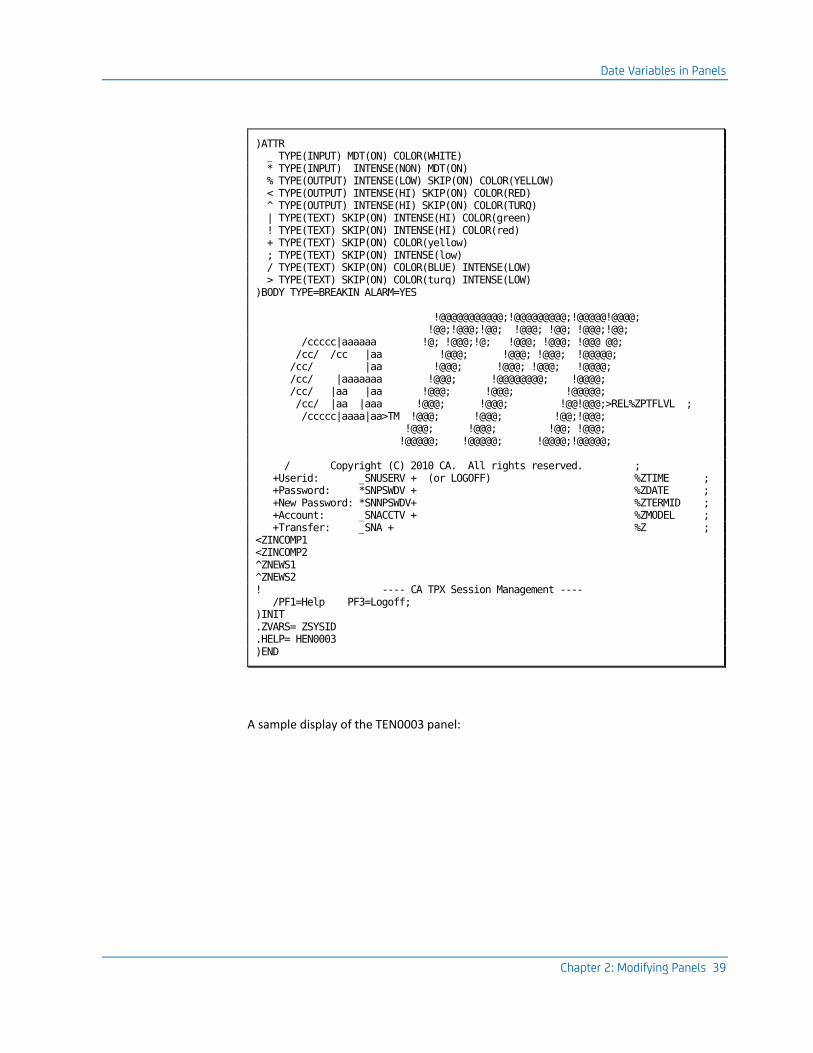
Date Variables in Panels
Chapter 2: Modifying Panels 39
)ATTR _ TYPE(INPUT) MDT(ON) COLOR(WHITE) * TYPE(INPUT) INTENSE(NON) MDT(ON) % TYPE(OUTPUT) INTENSE(LOW) SKIP(ON) COLOR(YELLOW) < TYPE(OUTPUT) INTENSE(HI) SKIP(ON) COLOR(RED) ^ TYPE(OUTPUT) INTENSE(HI) SKIP(ON) COLOR(TURQ) | TYPE(TEXT) SKIP(ON) INTENSE(HI) COLOR(green) ! TYPE(TEXT) SKIP(ON) INTENSE(HI) COLOR(red) + TYPE(TEXT) SKIP(ON) COLOR(yellow) ; TYPE(TEXT) SKIP(ON) INTENSE(low) / TYPE(TEXT) SKIP(ON) COLOR(BLUE) INTENSE(LOW) > TYPE(TEXT) SKIP(ON) COLOR(turq) INTENSE(LOW) )BODY TYPE=BREAKIN ALARM=YES !@@@@@@@@@@@;!@@@@@@@@@;!@@@@@!@@@@; !@@;!@@@;!@@; !@@@; !@@; !@@@;!@@; /ccccc|aaaaaa !@; !@@@;!@; !@@@; !@@@; !@@@ @@; /cc/ /cc |aa !@@@; !@@@; !@@@; !@@@@@; /cc/ |aa !@@@; !@@@; !@@@; !@@@@; /cc/ |aaaaaaa !@@@; !@@@@@@@@; !@@@@; /cc/ |aa |aa !@@@; !@@@; !@@@@@; /cc/ |aa |aaa !@@@; !@@@; !@@!@@@;>REL%ZPTFLVL ; /ccccc|aaaa|aa>TM !@@@; !@@@; !@@;!@@@; !@@@; !@@@; !@@; !@@@; !@@@@@; !@@@@@; !@@@@;!@@@@@; / Copyright (C) 2010 CA. All rights reserved. ; +Userid: _SNUSERV + (or LOGOFF) %ZTIME ; +Password: *SNPSWDV + %ZDATE ; +New Password: *SNNPSWDV+ %ZTERMID ; +Account: _SNACCTV + %ZMODEL ; +Transfer: _SNA + %Z ; <ZINCOMP1 <ZINCOMP2 ^ZNEWS1 ^ZNEWS2 ! ---- CA TPX Session Management ---- /PF1=Help PF3=Logoff; )INIT .ZVARS= ZSYSID .HELP= HEN0003 )END
A sample display of the TEN0003 panel:

Date Variables in Panels
40 Programming Guide

Date Variables in Panels
Chapter 2: Modifying Panels 41
TEN1003 – User Signon Panel for Password Phrase/Password Verification
The TEN1003 panel allows users at customer sites to sign on to TPX. The TEN1003 panel requires sites to be use either ACF2, Top Secret or RACF security systems. The RACF sites must configure TPX to use the SAF security not RACF.
CA ACF2 R15 (Z/OS) and CA ACF2 R14 (Z/OS) sites must apply ACF2 APAR RO38461 before attempting to use the TPX Password Phrase interface.
The TEN1003 panel accepts either password phrases or passwords on the sign-on panel. The TEN1003 panel allows users at a site to verify:
■ A valid userid and password phrase combination has been entered.
■ A valid password phrase and new password phrase has been entered.
■ A valid userid and password combination has been entered.
■ A valid password and new password has been entered.
TPX also supplies a TEN0003 panel that allows users to sign on with only a traditional one through eight character passwords.
A TPX site administrator configures the sign-on panel by updating the Default LOGO: field on the User Signon panel on the TPX System Options Table Detail Panel (Panel TEN0108):
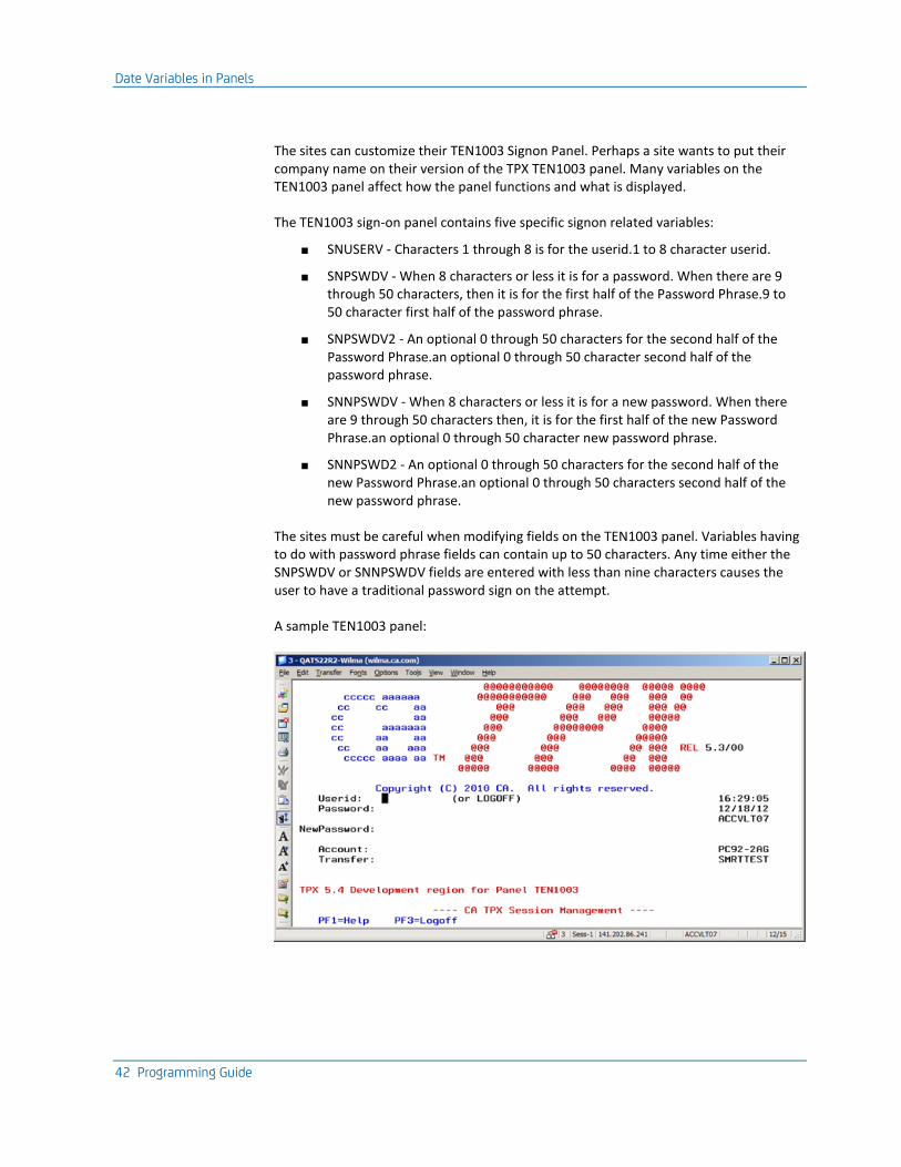
Date Variables in Panels
42 Programming Guide
The sites can customize their TEN1003 Signon Panel. Perhaps a site wants to put their company name on their version of the TPX TEN1003 panel. Many variables on the TEN1003 panel affect how the panel functions and what is displayed.
The TEN1003 sign-on panel contains five specific signon related variables:
■ SNUSERV - Characters 1 through 8 is for the userid.1 to 8 character userid.
■ SNPSWDV - When 8 characters or less it is for a password. When there are 9 through 50 characters, then it is for the first half of the Password Phrase.9 to 50 character first half of the password phrase.
■ SNPSWDV2 - An optional 0 through 50 characters for the second half of the Password Phrase.an optional 0 through 50 character second half of the password phrase.
■ SNNPSWDV - When 8 characters or less it is for a new password. When there are 9 through 50 characters then, it is for the first half of the new Password Phrase.an optional 0 through 50 character new password phrase.
■ SNNPSWD2 - An optional 0 through 50 characters for the second half of the new Password Phrase.an optional 0 through 50 characters second half of the new password phrase.
The sites must be careful when modifying fields on the TEN1003 panel. Variables having to do with password phrase fields can contain up to 50 characters. Any time either the SNPSWDV or SNNPSWDV fields are entered with less than nine characters causes the user to have a traditional password sign on the attempt.
A sample TEN1003 panel:
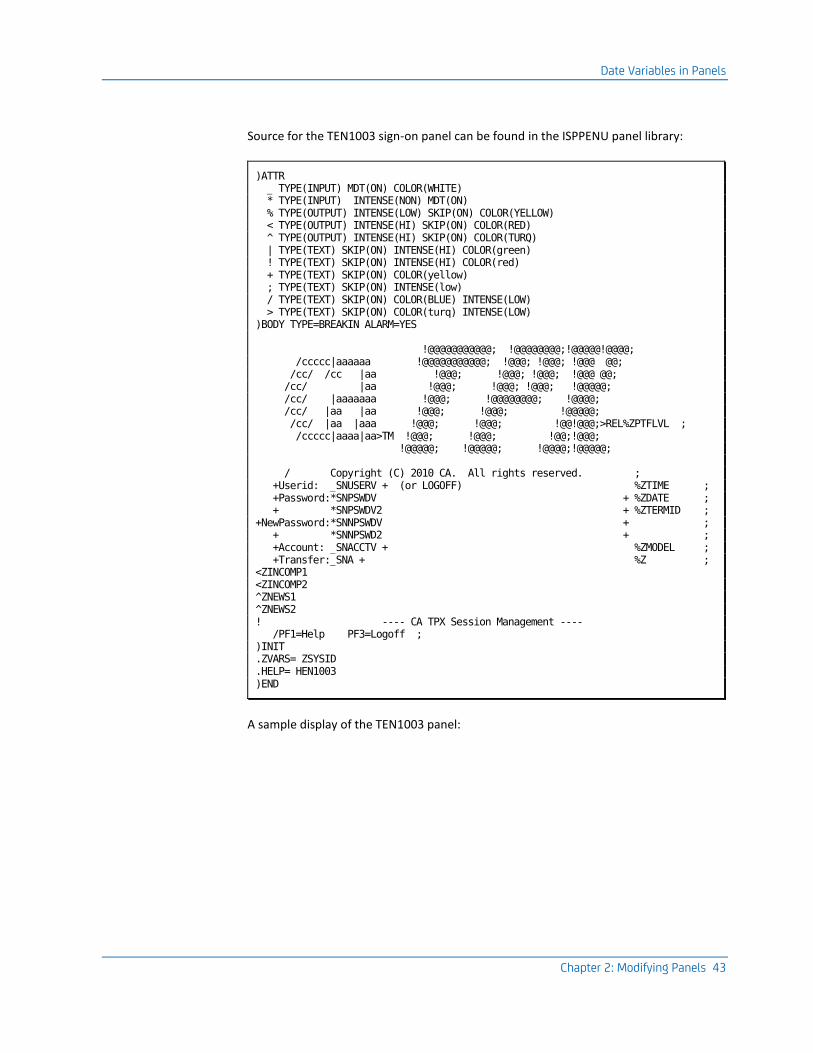
Date Variables in Panels
Chapter 2: Modifying Panels 43
Source for the TEN1003 sign-on panel can be found in the ISPPENU panel library:
)ATTR _ TYPE(INPUT) MDT(ON) COLOR(WHITE) * TYPE(INPUT) INTENSE(NON) MDT(ON) % TYPE(OUTPUT) INTENSE(LOW) SKIP(ON) COLOR(YELLOW) < TYPE(OUTPUT) INTENSE(HI) SKIP(ON) COLOR(RED) ^ TYPE(OUTPUT) INTENSE(HI) SKIP(ON) COLOR(TURQ) | TYPE(TEXT) SKIP(ON) INTENSE(HI) COLOR(green) ! TYPE(TEXT) SKIP(ON) INTENSE(HI) COLOR(red) + TYPE(TEXT) SKIP(ON) COLOR(yellow) ; TYPE(TEXT) SKIP(ON) INTENSE(low) / TYPE(TEXT) SKIP(ON) COLOR(BLUE) INTENSE(LOW) > TYPE(TEXT) SKIP(ON) COLOR(turq) INTENSE(LOW) )BODY TYPE=BREAKIN ALARM=YES !@@@@@@@@@@@; !@@@@@@@@;!@@@@@!@@@@; /ccccc|aaaaaa !@@@@@@@@@@@; !@@@; !@@@; !@@@ @@; /cc/ /cc |aa !@@@; !@@@; !@@@; !@@@ @@; /cc/ |aa !@@@; !@@@; !@@@; !@@@@@; /cc/ |aaaaaaa !@@@; !@@@@@@@@; !@@@@; /cc/ |aa |aa !@@@; !@@@; !@@@@@; /cc/ |aa |aaa !@@@; !@@@; !@@!@@@;>REL%ZPTFLVL ; /ccccc|aaaa|aa>TM !@@@; !@@@; !@@;!@@@; !@@@@@; !@@@@@; !@@@@;!@@@@@; / Copyright (C) 2010 CA. All rights reserved. ; +Userid: _SNUSERV + (or LOGOFF) %ZTIME ; +Password:*SNPSWDV + %ZDATE ; + *SNPSWDV2 + %ZTERMID ; +NewPassword:*SNNPSWDV + ; + *SNNPSWD2 + ; +Account: _SNACCTV + %ZMODEL ; +Transfer:_SNA + %Z ; <ZINCOMP1 <ZINCOMP2 ^ZNEWS1 ^ZNEWS2 ! ---- CA TPX Session Management ---- /PF1=Help PF3=Logoff ; )INIT .ZVARS= ZSYSID .HELP= HEN1003 )END
A sample display of the TEN1003 panel:
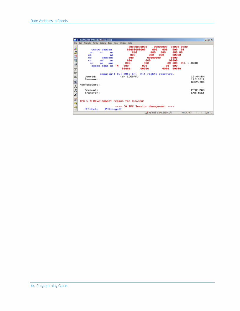
Date Variables in Panels
44 Programming Guide
Chapter 3: Special Features and Customization Tasks 45
Chapter 3: Special Features and Customization Tasks
This chapter shows you how to perform additional customization tasks that are available.
This section contains the following topics:
TCPaccess Telnet Server Interface (see page 45) Affinity Feature (see page 46) Pass Ticket Feature (see page 48) Specify Access Modes (see page 56) How to Customize Security (see page 57) Additional Security Options (see page 61) Profile Selection for Dynamic Users (see page 64) Customize the APTPX Member (see page 68) Customize Logon Mode Tables (see page 74) Adjust Storage Parameter (see page 76) Slot Pool Storage and Analysis Reports (see page 81) Mail Facility (see page 84) View Facility (see page 86) Control Application Sessions with OPENGATE (see page 87) Advanced Data Compression (see page 91) Implement Tiered Menus (see page 93)
TCPaccess Telnet Server Interface
The TCPaccess Telnet Server interface provides native Internet Protocol (IP) support. The interface provides for a direct connection between CA TPX and TCPaccess Telnet Server, eliminating the need for a VTAM session on behalf of each TN3270 client.
You must install TCPaccess Telnet Server and activate it on the same operating system image as CA TPX.
Activate the Interface
To set up the TCPaccess Telnet Server interface, you must modify the CA TPX startup procedure and startup job stream. For details, see the Installation Guide.
To activate the interface, you must set an option in the System Options Table (SMRT), under System Features. Specify Y in the Activate TCPaccess Telnet Interface field. To put the change into effect, you must recycle CA TPX.
Affinity Feature
46 Programming Guide
CA TPX will wait for the TCPaccess Telnet Server to contact it. For information on how to activate the CA TPX interface on the Server, see the CA TCPaccess Telnet Server Customization Guide, the appendix "Native IP Interface."
Important Notes
Because CA TPX performs all the SNA functionality on behalf of the TN3270 client, it must remain in control of all application sessions on behalf of the client at all times. Therefore, when using the interface, the following CA TPX features are not available:
■ Affinity feature
■ Pass Mode
■ The Pass Option on application definitions
When using the interface, settings in the SMRT pertaining to these features are ignored.
TCPaccess Telnet Server is mutually exclusive with the VTAM Generic Resource Option. This is because VTAM does not participate in any aspect of the terminal session from the perspective of CA TPX.
Affinity Feature
The affinity feature allows you to have a particular CA TPX take control of a user's sessions even if the user signs on from a terminal that is controlled by a different system. You can set up the affinity feature through an online administration session or with the signon and signoff user exit.
You can use the affinity feature to balance the terminal traffic load across several CPUs, pass terminals to a system in the domain that owns them, or pass users to the system that is closest to the applications they use most. If CA TPX is operating as a generic resource, this setting will override any selection made by VTAM and Workload Manager.
How the /F Command Works
When users issue the /F command from a system they have been passed to, the /F command is executed as a /K command. This does not occur if you specify Y in the Change Signoff to Logoff field of the System Options Table (SMRT).
Turning the Affinity Field On
To use the affinity feature, you must set the Affinity field in the System Options Table (SMRT) to Y for the original CA TPX (the one the user is signing on to).
Affinity Feature
Chapter 3: Special Features and Customization Tasks 47
Establish Affinity for a User
If you want to allow a user administrator to establish affinity for a user or profile, you must first make the CA TPX system a member of an affinity group, as described in Establishing Affinity Between Systems.
Establish Affinity with a User Exit
You can use the signon and signoff user exit (TPXUSNSF) to select the system that is to receive control of a user's session. For a description of the exit, see the chapter Setting Up User Exits (see page 129).
Propagate Password Changes
You can set CA TPX to propagate password changes when a user is transferred to a system that they have affinity with. This will cause password changes to be updated on the CA TPX to which they are transferred.
If the different systems are running on different security files, this ensures that if a password expires on one system before it expires on other systems, the new password is propagated.
To propagate passwords, specify Y in the Propagate Pswd Change field of the System Options Table (SMRT).
Establish Affinity Between Systems
You can establish affinity between multiple CA TPX systems on multiple hosts. Affinity on multiple hosts ensures that, when the host owning a set of terminals is down, the host acquiring ownership will interact with the end users in the same way as the original host.
To establish affinity between systems on multiple hosts
1. Specify a common alias name for each system included in the affinity group. You specify this name on the ACBNAME parameter of the APPL statement in SYS1.VTAMLST.
For example, if you are running system TPX01 on HOST1, and system TPX02 on HOST2, and you want to give them the common alias name TPXALL, the APPL statements would look like this:
TPX01 on HOST1:
TPX,PRIMARY
TPX01 APPL MODETAB=TPXLGMOD,LOGMODE=T3278M3,ACBNAME=TPXALL

Pass Ticket Feature
48 Programming Guide
TPX02 on HOST2:
TPX,PRIMARY
TPX02 APPL MODETAB=TPXLGMOD,LOGMODE=T3278M3,ACBNAME=TPXALL
2. Establish a controlling relationship between the affinity group and all or selected terminals by adding a LOGAPPL parameter to the terminal major node definitions in SYS1.VTAMLST.
The name you specify in the LOGAPPL parameter must match the alias name that you defined in the ACBNAME parameter in step 1. This causes VTAM to automatically log the terminal on to the CA TPX system in the VTAM domain that owns the terminal. (You can change ownership with the VTAM VARY NET,ACQUIRE command.)
In the example in step 1, the name of the affinity group to which the systems TPX01 and TPX02 belong is TPXALL, so the value in the LOGAPPL parameter must be TPXALL. A terminal major node definition for either system might look like this:
TERMABCD LU LOCADDR=5, X
DLOGMOD=USERMDL2, X
MODETAB=USERTABL, X
USSTAB=USERUSS, X
LOGAPPL=TPXALL, X
ISTATUS=ACTIVE
Note: ACF/VTAM's LOGAPPL processing can be inhibited if one of the following conditions occurs:
■ CA TPX is not active
■ The terminal is not active
■ The owning application terminates its session
Pass Ticket Feature
A pass ticket is a one-time only password substitute that is automatically generated by an authentication server, such as IBM's Network Security Program or CA's Single Signon Option, on behalf of a client workstation requesting access to a mainframe application like CA TPX. After a user is signed on, pass tickets can also be generated for applications subsequently accessed through this product. The use of pass tickets requires you to complete administrative maintenance.
The pass ticket eliminates the need for users to manually type their password on the TPX logon screen and eliminates the transmittal of the same password in clear text across networks. The feature also provides application security, because a pass ticket is a one-time only password.
Pass tickets are supported by CA ACF2, CA Top Secret, and RACF.
Pass Ticket Feature
Chapter 3: Special Features and Customization Tasks 49
Qualified and Nonqualified Pass Tickets
Qualified and nonqualified pass tickets are supported. A nonqualified pass ticket is associated with a specific application and can be used for any user during the period it is valid. A qualified pass ticket is associated with an application and is further qualified by association with a user ID, group ID, or both, and is valid only for use by the defined combination for the period it is valid, thereby providing better security.
Requirements for Pass Ticket
Nonqualified Pass Tickets
The requirements for the use of nonqualified pass tickets are as follows:
■ The application must use external security through RACF, CA ACF2, CA Top Secret or SAF, or must itself support pass ticket verification.
■ If using external security, the application must supply the security system with information required to permit pass ticket verification.
■ The application must be defined in CA TPX with session data that contains &PSWD or a startup ACL that keys in &PSWD to ensure secured signon using Pass Ticket.
The parameters to turn on the Generate Pass Ticket feature can be set on any product image that has access to the administration files.
Qualified Pass Tickets
Generation of qualified pass tickets by CA TPX requires CA ACF2 or CA Top Secret as the underlying security system on the operating system image on which CA TPX is active. The parameters to turn on the Generate Qualified Pass Ticket feature can be set on any product image that has access to the administration files.
To use qualified pass tickets, you must set up the appropriate pass ticket profile in CA ACF2 or CA Top Secret. Refer to the documentation for those products.
If the target application is running on a remote system from CA TPX, the pass ticket profile must be identical on all the remote systems where the application resides (regardless of the security system used on each of those systems) and on the CA TPX system, which must be using CA ACF2 or CA Top Secret.
If the target application is on a system that is secured by a non-CA solution (such as RACF), consult the security solution documentation for the required settings.
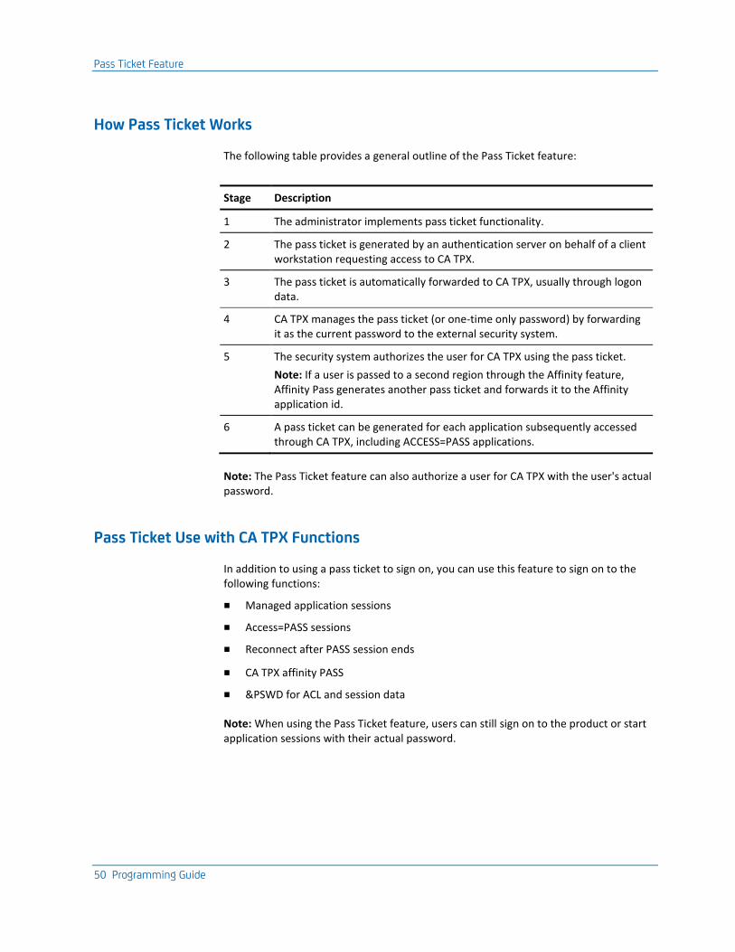
Pass Ticket Feature
50 Programming Guide
How Pass Ticket Works
The following table provides a general outline of the Pass Ticket feature:
Stage Description
1 The administrator implements pass ticket functionality.
2 The pass ticket is generated by an authentication server on behalf of a client workstation requesting access to CA TPX.
3 The pass ticket is automatically forwarded to CA TPX, usually through logon data.
4 CA TPX manages the pass ticket (or one-time only password) by forwarding it as the current password to the external security system.
5 The security system authorizes the user for CA TPX using the pass ticket.
Note: If a user is passed to a second region through the Affinity feature, Affinity Pass generates another pass ticket and forwards it to the Affinity application id.
6 A pass ticket can be generated for each application subsequently accessed through CA TPX, including ACCESS=PASS applications.
Note: The Pass Ticket feature can also authorize a user for CA TPX with the user's actual password.
Pass Ticket Use with CA TPX Functions
In addition to using a pass ticket to sign on, you can use this feature to sign on to the following functions:
■ Managed application sessions
■ Access=PASS sessions
■ Reconnect after PASS session ends
■ CA TPX affinity PASS
■ &PSWD for ACL and session data
Note: When using the Pass Ticket feature, users can still sign on to the product or start application sessions with their actual password.

Pass Ticket Feature
Chapter 3: Special Features and Customization Tasks 51
Operational Difference for Pass Ticket Users
If a user is defined under administration as a Pass Ticket user, the following limitations apply:
■ There are no time-outs to LOCKSCREEN or the logo (signon) screen. (The benefit of Pass Ticket is voided, if a user must type a password on the logo screen or the LOCKSCREEN.)
■ The following signoffs return the user to VTAM or NETWORK solicitor:
– SIGNOFF (any)
– /F
– ACL SIGNOFF
– A generated signoff
■ If a user wants to use the /L command, a LOCKWORD must be supplied by the user wanting to be reconnected to CA TPX.
■ Stage one time outs to the lock screen and all time outs that would normally generate a SIGNOFF, will instead time out to VTAM (meaning a /K is generated).
Pass Ticket Reconnections
A reconnect after a pass session generates a pass ticket.
&PSWD Variable Becomes Unusable
After a user signs on using a pass ticket, the &PSWD variable becomes unusable. This is true because the product cannot distinguish a pass ticket from a password, and will store the pass ticket as if it were a password. But, because the pass ticket is good for one signon only, it thereafter becomes invalid, and must be replaced with a new pass ticket for each subsequent session initiation. Any attempt to use the &PSWD variable as is results in password rejection.
Consequences of an Invalid &PSWD Variable
As previously stated, if a user has signed on with a pass ticket, the &PSWD variable becomes unusable. To successfully start an application session, one of the following two things must happen:
1. The user's real password must be sent to the application.
or
2. The product must generate a new pass ticket prior to session initiation.
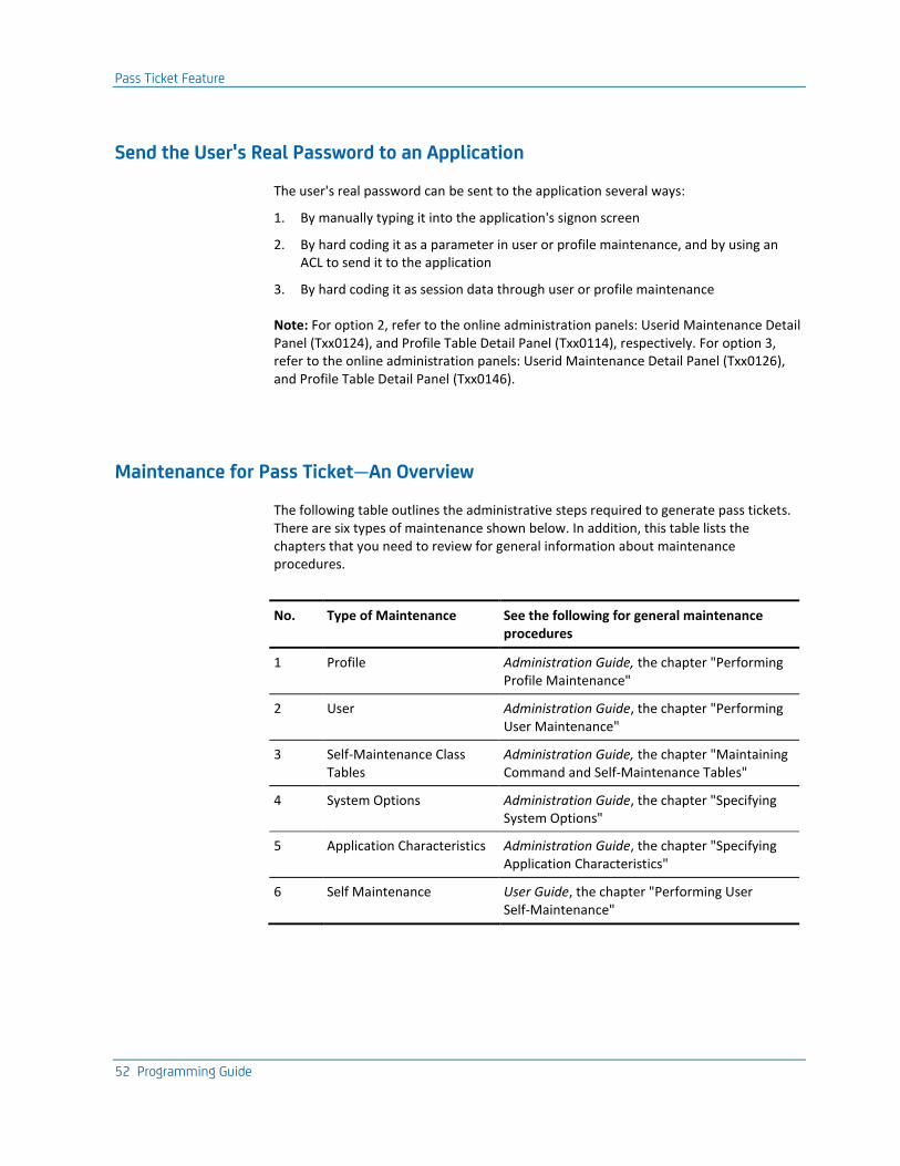
Pass Ticket Feature
52 Programming Guide
Send the User's Real Password to an Application
The user's real password can be sent to the application several ways:
1. By manually typing it into the application's signon screen
2. By hard coding it as a parameter in user or profile maintenance, and by using an ACL to send it to the application
3. By hard coding it as session data through user or profile maintenance
Note: For option 2, refer to the online administration panels: Userid Maintenance Detail Panel (Txx0124), and Profile Table Detail Panel (Txx0114), respectively. For option 3, refer to the online administration panels: Userid Maintenance Detail Panel (Txx0126), and Profile Table Detail Panel (Txx0146).
Maintenance for Pass Ticket—An Overview
The following table outlines the administrative steps required to generate pass tickets. There are six types of maintenance shown below. In addition, this table lists the chapters that you need to review for general information about maintenance procedures.
No. Type of Maintenance See the following for general maintenance procedures
1 Profile Administration Guide, the chapter "Performing Profile Maintenance"
2 User Administration Guide, the chapter "Performing User Maintenance"
3 Self-Maintenance Class Tables
Administration Guide, the chapter "Maintaining Command and Self-Maintenance Tables"
4 System Options Administration Guide, the chapter "Specifying System Options"
5 Application Characteristics Administration Guide, the chapter "Specifying Application Characteristics"
6 Self Maintenance User Guide, the chapter "Performing User Self-Maintenance"
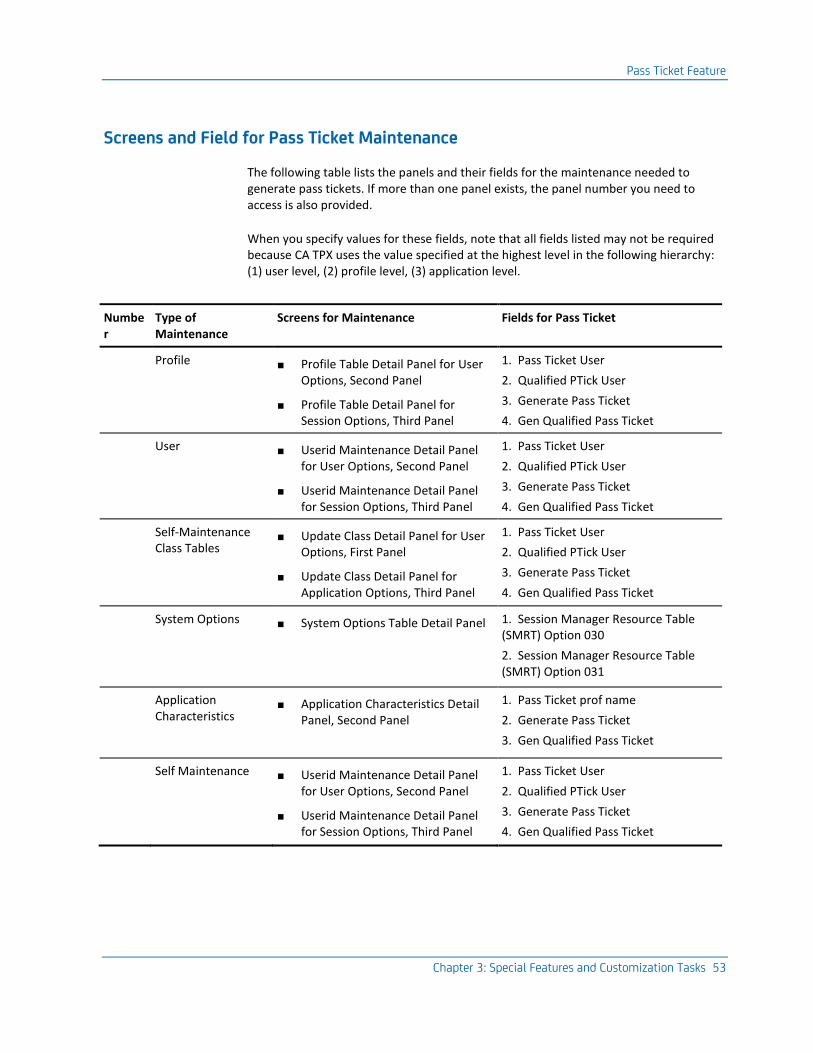
Pass Ticket Feature
Chapter 3: Special Features and Customization Tasks 53
Screens and Field for Pass Ticket Maintenance
The following table lists the panels and their fields for the maintenance needed to generate pass tickets. If more than one panel exists, the panel number you need to access is also provided.
When you specify values for these fields, note that all fields listed may not be required because CA TPX uses the value specified at the highest level in the following hierarchy: (1) user level, (2) profile level, (3) application level.
Number
Type of Maintenance
Screens for Maintenance Fields for Pass Ticket
1 Profile ■ Profile Table Detail Panel for User
Options, Second Panel
■ Profile Table Detail Panel for Session Options, Third Panel
1. Pass Ticket User
2. Qualified PTick User
3. Generate Pass Ticket
4. Gen Qualified Pass Ticket
2 User ■ Userid Maintenance Detail Panel
for User Options, Second Panel
■ Userid Maintenance Detail Panel for Session Options, Third Panel
1. Pass Ticket User
2. Qualified PTick User
3. Generate Pass Ticket
4. Gen Qualified Pass Ticket
3 Self-Maintenance Class Tables
■ Update Class Detail Panel for User Options, First Panel
■ Update Class Detail Panel for Application Options, Third Panel
1. Pass Ticket User
2. Qualified PTick User
3. Generate Pass Ticket
4. Gen Qualified Pass Ticket
4 System Options ■ System Options Table Detail Panel 1. Session Manager Resource Table
(SMRT) Option 030
2. Session Manager Resource Table (SMRT) Option 031
5 Application Characteristics
■ Application Characteristics Detail Panel, Second Panel
1. Pass Ticket prof name
2. Generate Pass Ticket
3. Gen Qualified Pass Ticket
6 Self Maintenance ■ Userid Maintenance Detail Panel
for User Options, Second Panel
■ Userid Maintenance Detail Panel for Session Options, Third Panel
1. Pass Ticket User
2. Qualified PTick User
3. Generate Pass Ticket
4. Gen Qualified Pass Ticket
Pass Ticket Feature
54 Programming Guide
Field Definitions
This section defines each field available for maintenance.
Pass Ticket User and Qualified PTick User Fields
The following values are valid for both the Pass Ticket User and Qualified PTick User fields wherever they appear, except on the Self-Maintenance Class Tables.
Valid values are Y (Yes), N (No), or null:
Y
Specify Y if users of this profile are expected to sign on through Pass Ticket. It is the user's responsibility to fully implement this functionality, because there is no way to determine if the user signs on with a pass ticket or an actual password.
N or null
Specify N or null, if you do not expect users of this profile to sign on using pass tickets.
Note: Pass ticket generation for application sessions is handled separately and is independent of a user's method of signing on to CA TPX.
Generate Pass Ticket and Gen Qualified Pass Ticket Fields
The following values are valid for both the Generate Pass Ticket and Gen Qualified Pass Ticket fields wherever they appear, except on the Self-Maintenance Class Tables.
Valid values are Y (Yes), N (No), or null. This value overrides the value for the same field specified in the Application Characteristics Table (ACT).
Y
Specify Y to generate a pass ticket when a session with this application is started. The &PSWD variable for this application is set to the value of the generated pass ticket at the start of the application session.
N
Specify N if you do not want a pass ticket generated for this application.
Null
Indicates use of the specification from the ACT for this application.
Any combination of valid values for both Generate Pass Ticket and Gen Qualified Pass Ticket is permitted. CA TPX attempts to use the most secure form of pass ticket available based of the settings in CA TPX and the Pass Ticket Profile, if any, as defined in the external security system.
Pass Ticket Feature
Chapter 3: Special Features and Customization Tasks 55
If CA TPX determines that a qualified pass ticket is requested but not available, and a nonqualified pass ticket is not permitted (that is, Generate Pass Ticket set to N or null), the requested session is not started and the user is notified.
Self-Maintenance Class Tables
Update Class Detail Panel for User Options, First Panel
__ 1. Pass Ticket User
__ 2. Qualified PTick User
Valid values are Y (Yes), N (No), or null. The default is N.
Y
Specify Y if the user is permitted to update the pass ticket fields on user maintenance screens for user options.
N
Specify N if you do not want the user to have this capability.
Update Class Detail Panel for Applications Options, Third Panel
__ 3. Generate Pass Ticket
__ 4. Generate Qualified Pass Ticket
Valid values are Y (Yes) or N (No). The default is N.
Y
Specify Y to allow the user to update the generate pass ticket fields on the user maintenance screen for session options.
N
Specify N if you do not want the user to have this capability.
System Options Maintenance
System Options Table Detail Panel
__ 1. Session Manager Resource Table (SMRT) Option 030 - Valid values are Y (Yes) or N (No). The default value is N.
Y
Specify Y to allow users defined as Pass Ticket users to return to the logo screen when the signoff command (/F) is entered or generated. Pass Ticket users do not typically see the logo screen when a /F command is entered or generated.
Specify Access Modes
56 Programming Guide
Note: If a user returns to the logo screen and then subsequently signs on with an actual password, the user does not have a secured signon through Pass Ticket.
__ 2. Session Manager Resource Table (SMRT) Option 031 - Valid values are Y (Yes) or N (No). The default value is N.
Y
Causes the words "pass ticket" to be placed on the CA TPX menu in the place where "check messages" appears (the W3 variable). The "check messages" indication temporarily overrides the "pass ticket" indication. In addition, if a user is not defined as a Pass Ticket user, but individual applications on the menu are defined as Pass Ticket applications, then the letters "PTIX" or the words "pass ticket" will appear in the "status" column (the UENTWSTS or UENTWSTL variables) on the menu. Other values will temporarily take precedence over these values.
Application Characteristics Maintenance
Application Characteristics Detail Panel, Second Panel
Pass Ticket Prof Name
For TSO and for VM systems, this is the name by which the application is known to the security system, which is different from the VTAM applid. For TSO, this name should be "TSOsmfid" and for VM, this name should be "VMcpuid". If in doubt, consult your security system administrator.
Configuration
Be advised that your security system administrator must configure your system for use of this feature, if you want to sign on and access functions using pass tickets.
Related Publications
For further information about pass tickets, see the documentation for CA ACF2, CA Top Secret, and RACF.
Specify Access Modes
The access mode defines the type of access to applications. You define the access mode on the System Options Table (SMRT), as described in the Administration Guide. A user administrator can specify a lower, but never higher, level of access in a profile or user definition.
How to Customize Security
Chapter 3: Special Features and Customization Tasks 57
You can define the following access modes:
MULTIPLE (default)
Allows a user to communicate with an unlimited number of applications at the same time.
Note: Setting the access mode to MULTIPLE allows a user administrator to define the mode as SINGLE or PASS at the profile or user level.
SINGLE
Allows a user to communicate with only one application at a time. The user can still access the Menu and use the print key and other features while an application session is active.
Note: Setting the access mode to SINGLE allows a user administrator to define the mode as PASS, but not MULTIPLE, at the profile or user level.
PASS
Provides the user with a simplified mode of access to applications. The user receives the Menu at signon. After the user activates a session, the product passes control of the physical terminal to the application, and the user cannot access the Menu or any other features while the application session is active.
Notes:
■ Setting the access mode to PASS prohibits a user administrator from defining other access modes at the profile or user level.
■ You cannot use PASS mode when using the TCPaccess Telnet Server interface.
How to Customize Security
When you customize your system, you must specify information concerning the security system. This information depends on the security system used at your site. The following sections explain the steps needed to customize this product for your site.
Customize Security When Security System Is SAF
To customize your system when your Security System is SAF
1. Specify SAF in the Security System field of the System Options Table (SMRT).
2. Put the application in an APF-authorized library, as described in the Installation Guide.
How to Customize Security
58 Programming Guide
3. If your site uses APPL class rules, you can specify in the software an alias for the VTAM PLU name. This allows you to:
■ Use a different name if you cannot use the existing PLU name.
■ Refer to a number of copies of the product with one alias, so only one APPL class rule applies to all copies using the alias.
Specify the alias in the Alias Name field of the SMRT.
4. If you are running RACF r1.8 or later, SAF can return messages. To allow these messages to be displayed, specify Y in the Return Messages from SAF field of the SMRT.
Notes for SAF Users:
■ Specifying the SAF interface when you are using RACF will allow you to use features that are otherwise unavailable.
■ Specifying the SAF interface when you are using CA ACF2 or CA Top Secret will reduce functionality, because the software makes native calls to these products. It cannot make these calls if the SAF interface is used.
■ You can use the Security Action/Message Table to customize the response of this product to messages produced by SAF. For more information about using this table, see the Administration Guide.
Customize Security When Security System Is RACF
To customize your system when the Security System is RACF
1. Specify RACF in the Security System field of the System Options Table (SMRT).
2. Put the application in an APF-authorized library, as described in the Installation Guide.
3. If your site uses APPL class rules, you can specify in the software an alias for the VTAM PLU name. This allows you to:
■ Use a different name if you cannot use the existing PLU name.
■ Refer to a number of copies of the product with one alias, so only one APPL class rule applies to all copies using the alias.
Specify the alias in the Alias Name field of the SMRT.
Notes for RACF Users:
■ Use the SAF interface instead of RACF. This allows you to use features such as security messages.
■ You can use the Security Action/Message Table (SAMT) to customize the response of this product to messages produced by RACF. For information about using this table, see the Administration Guide.
How to Customize Security
Chapter 3: Special Features and Customization Tasks 59
Customize Security When Security System Is CA Top Secret
To customize your system when the Security System is CA Top Secret
1. Specify TOPS in the Security System field of the System Options Table (SMRT).
2. Put your application modules in an APF-authorized library, as described in the Installation Guide.
3. Specify the following statements in the CA Top Secret ACID table:
FAC(USER1=NAME=TPX)
FAC(PGM=TPX)
FAC(TPX=(ACTIVE,SHRPRF,MULTIUSER,AUTHINIT))
4. If your site uses APPL class rules, you can specify in the software an alias for the VTAM PLU name. This allows you to:
■ Use a different name if you cannot use the existing PLU name.
■ Refer to a number of copies of the product with one alias, so only one APPL class rule applies to all copies using the alias.
Specify the alias in the Alias Name field of the SMRT.
Notes for CA Top Secret Users:
■ CA Top Secret must be completely operational before CA TPX is started.
■ CA Top Secret can issue the TPX START command.
■ You can use the Security Action/Message Table (SAMT) to customize the response of this product to messages produced by CA Top Secret. For information about using this table, see the Administration Guide.
Customize Security When Security System Is CA ACF2
To customize your system when your Security System is CA ACF2
1. Specify CA ACF2 in the Security System field of the System Options Table (SMRT).
2. Put the application in an APF-authorized library, as described in the Installation Guide.
3. If you are running the product as a Multiple User Single Address Space System (MUSASS), you must:
■ Code an @MUSASS macro for the CA TPX region in the CA-ACF2 Field Definition Record (ACFFDR).
■ Assign the MUSASS attribute to the CA TPX region logonID.
■ IPL the system.
How to Customize Security
60 Programming Guide
4. If you are not running the product as a MUSASS, you must specify Y in the Bypass MUSASS Processing field of the SMRT.
5. If the CA ACF2 CVT is pointed to by the CVTUSER field, specify CVTUSER in the CVT Location field of the SMRT.
6. If the CA ACF2 CVT is offset into the ACTUSER area, specify OFFSET in the CVT Location field of the SMRT. You must also specify the offset in the CVT Offset field of the SMRT.
7. If you are using an attribute byte for the product, examine the CA ACF2 Logon ID record (LIDREC) and determine the location of the attribute byte.
Specify the location of the byte in the Auth Offset field of the SMRT.
8. Examine the byte for the location of the CA TPX bit.
Specify the location of the bit in the Auth Mask field of the SMRT.
Notes for CA ACF2 Users:
You can use the Security Action/Message Table (SAMT) to customize the response of the product to messages produced by CA ACF2. For information on using this table, see the Administration Guide.
Customize Security When Security System Is CA TPX Security
When your Security System is CA TPX Security, specify TPX in the Security System field of the System Options Table (SMRT).
Note: Users must specify a password the first time they sign on.
Customize Security When Security System Is User Exit Security
To use the TPXUSNSF as your security system
1. Specify USER in the Security System field of the System Options Table (SMRT).
2. Specify the TPXUSNSF user exit. For information, see the chapter Setting Up User Exits (see page 129).
Use CA TPX Security to Access CA STX
If you also have the CA STX component, you can set up your security so CA STX security validation is not performed for users who have been validated when signing on to this product. It is called enhanced CA TPX security.

Additional Security Options
Chapter 3: Special Features and Customization Tasks 61
To operate with the enhanced CA TPX security
1. Specify enhanced security for CA STX in the CA TPX ACT.
2. Ensure that the session data transmitted from CA TPX includes a valid user ID, even when you specify NONE as the security system for CA STX. With enhanced security, there is no pre- or post-security call in which to assign a default profile.
Enhanced Security Process
With enhanced security, the following process takes place when users access CA STX:
1. The user selects CA STX from the Menu.
2. The product transmits the VTAM logon data, with a special token concatenated in front.
■ Logon data is transmitted as token/userid/password if there is no session data defined for CA STX in the ACT
■ Logon data is transmitted as token/session data if session data is defined.
In both cases, the product scrambles and encrypts the data to secure the user's password.
Although data is encrypted, enhanced security does not use the product's encryption exit.
3. CA STX decrypts and unscrambles the logon data and saves the password in its re-encrypted form.
4. CA STX bypasses the signon security call unless the following conditions exist:
■ You specified USER as the type of security. In this case, the call allows you to customize CA STX security.
■ You specified that file security be done under RACF or CA ACF2. In this case, the file cannot be opened without the call.
Additional Security Options
You can perform addition customization with your security system to improve the way the product operates with your security system.
Additional Security Options
62 Programming Guide
Use User Names from the Security System
If you are using RACF, SAF, CA ACF2, or CA Top Secret, you can set the product to take advantage of the user name field specified in your security system. This product can copy the user name from the user record in the security system to the user record in the ADMIN file. This allows you to maintain the user name in the application without keying in the information via user administration.
This capability is controlled by the Write User Info to File field in the System Option Table (SMRT).
■ If set to Y, the information will be copied from the security system when the user signs on.
■ If set to N, the information is not copied.
Bypass New Password Verification
If you are using RACF, SAF, CA ACF2, or CA Top Secret, you can set the product to bypass new password verification. Normally, users are prompted to re-enter their new passwords after they enter them the first time. When this option is set, they do not have to re-enter the password.
Important! If you use this option a possible security problem exists. An unauthorized user could fill in the new password field on a Logo panel. Then another user could sign on normally, entering their user ID and password. Because the new password field has been filled and is not verified, that new password will go into effect without the user's knowledge.
Also, if a user makes a mistake while entering the new password, there is no way to verify the password before it takes effect.
To bypass verification, specify Y in the Bypass New Pswd Reverification field of the System Options Table (SMRT).
Security Action/Message Table
If you are using RACF, SAF, CA ACF2, or CA Top Secret, you can use the Security Action/Message Table (SAMT) to customize how the product handles return codes and messages from your security system. The SAMT can be maintained by system administrators through online administration. For information on using the SAMT, see the Administration Guide.
Additional Security Options
Chapter 3: Special Features and Customization Tasks 63
The table allows you to:
■ Specify a message to be displayed if a specific return code or message is received from the security system.
■ Specify that the product allow a user to signon, reject a signon attempt, re-prompt the user, or log the terminal off, depending on the return code or message received from the security system.
■ Specify the cursor position if the product rejects a signon attempt or re-prompts the user.
■ Suppress messages from the security system.
■ Replace security system messages with custom messages.
Use External Security to Determine Applications on TPX Menu
You can use external security to determine the applications that will appear on the TPX Menu for a given user.
■ A profile must be built in CA TPX for each application (one application per profile). It is possible to put more than one application in a single profile, but you would then have to permit them as a group.
■ A profile marked "Profile Should Be First" must be created for each set of menu parameters (menu key, tag key, print key, and so on). Applications would not be defined in this profile. All users would be given access to the appropriate profile for menu parameters.
■ In the Performance Parameters panel (TEN0101) under System Options, the Load Profiles at Startup field must be set to Y (see the Performance Parameters section of the chapter "Specifying System Options" in the Administration Guide).
■ A resource class (such as VTAMAPPL) must be defined in external security. Each profile name in CA TPX must be defined as a resource in this class. You must identify this resource class to CA TPX on panel TEN0090 in the Resource Class field. Additionally, the Profile Selection field must be set to PROF (see the Security Parameters section of the chapter "Specifying System Options" in the Administration Guide). Note that the field Default Dynamic User Profile on the System Features panel (TEN0105) is ignored.
Profiles in security will be built that contain permission for the application signon (facility) and permission for the menu name (resource). Users will be given permission to the profile that will, in a single step, give them access to the application and add the menu entry to their menu. Note that this permission is required today for each user and application; if defined properly, no additional administration is needed. Applications and their associated menu items can be grouped in security under a single security profile or nested profiles, as appropriate.
Profile Selection for Dynamic Users
64 Programming Guide
More information:
Frequently Asked Questions (see page 207)
Profile Selection for Dynamic Users
You can use your security interface to specify how the product determines profiles for dynamic users. Dynamic users are users who sign on but are not administered by a user administrator. For more information on profile selection, see Profile Selection for Dynamic Users (see page 64).
Suppress the Logo Panel
The Change Signoff to Logoff field in the System Options Table (SMRT) can be used to prevent the Logo panel from being displayed when a user signs off.
If your site is using enhanced user authentication, in which a security front end handles user signon and bypasses the Logo panel, you can use this option to ensure that the Logo panel is never displayed. To do this, specify Y in the Change Signoff to Logoff field of the Terminal Options Table.
Profile Selection for Dynamic Users
Dynamic users are users who are not maintained by user administration. Their profiles are not determined by records in the ADMIN files but are determined when the dynamic user logs on.
For a complete description of dynamic users, see the Administration Guide.
Profile Selection for Dynamic Users
Chapter 3: Special Features and Customization Tasks 65
Methods of Profile Selection
If you are using RACF, SAF, CA ACF2, or CA Top Secret, you can use one of the following methods to determine which profiles are assigned to dynamic users.
Method of Profile Selection Description
Specify a default profile in the SMRT.
You can specify a profile name in the Default Profile field of the System Options Table (SMRT). The profile specified in this field will be assigned to dynamic users when they sign on.
For procedures for modifying the SMRT, see the Administration Guide.
Specify ADDPROFs in a Signon/Signoff user exit.
You can write a signon/signoff exit that uses ADDPROFs to assign profiles to dynamic users when they sign on. Dynamic users are sent to the Get Profile call point of the signon user exit.
For information on using the signon/signoff exit, see the chapter Setting Up User Exits (see page 129).
Specify information in the security system to perform user-level or profile-level profile selection.
User-level selection involves specifying information in the user record that will allow the security system to determine which profiles can be assigned to the user.
Profile-level selection involves specifying rules in the security system that will allow the security system to determine which profiles can be assigned to which users.
How to Set Up User-level Profile Selection
User-level selection is implemented depending on which security system you are using. The following sections describe how to set up user-level profile selection depending on your security system.

Profile Selection for Dynamic Users
66 Programming Guide
Set Up User-level Profile Selection When Security System Is RACF or SAF
To set up User-level Profile Selection when your Security System is RACF or SAF
1. Specify Y in the Load Profiles at Startup field of the System Options Table (SMRT).
2. Specify USER in the Profile Selection field of the SMRT.
3. Define a profile in CA TPX for each group name in the security system.
Note: Only group names for which application sessions need to be associated must be defined as profiles.
In the profile, define the applications to be included in the user's menu when the profile is selected. CA TPX will include profiles corresponding to the group names in the security system in the list of profiles assigned to the user each time the user logs on.
CA TPX can also identify profiles to be included in the user's profile list by an alias name for a profile. Specify the alias name in the Security Alias field of the profile. If the group name in the security system matches the alias name of the profile, the profile will be included in the list of profiles.
Set Up User-level Profile Selection When Security System Is CA ACF2
To set up User-level Profile Selection when your Security System is CA ACF2
1. Specify Y in the Load Profiles at Startup field of the System Options Table (SMRT).
2. Specify USER in the Profile Selection field of the SMRT.
3. Turn on attribute bits in the user's LIDREC for each profile that you want to be included in the user's profile list.
4. Specify the profile bits:
■ Determine the offset of the profile bits from the beginning of the LIDREC or MLID.
■ Specify this offset value in the CA ACF2 Authorization Offset field of the profile definition.
■ Specify the hex value of the bit in the CA ACF2 Authorization Mask field of the profile definition.
5. Indicate the profile that should appear first in the user's list of profiles. Specify this by entering Y in the Profile Should be First field of the profile. This is done in Profile Maintenance in the product's administration.

Profile Selection for Dynamic Users
Chapter 3: Special Features and Customization Tasks 67
Set Up User-level Profile Selection When Security System Is CA Top Secret
To set up User-level Profile Selection when your Security System is CA Top Secret
1. Specify Y in the Load Profiles at Startup field of the System Options Table (SMRT).
2. Specify USER in the Profile Selection field of the SMRT.
3. Define INSTDATA for the profiles that you want to be included in the user's profile list. INSTDATA must have the following format:
otherdata,TPX(profname,profname,profname...),otherdata
The profname must be a one to eight character profile name. Separate each profile name by commas, and enclose the list in parentheses.
If you specify a value in the Resource Class field of the SMRT, the product will search the INSTDATA for that value rather than TPX.
The first profile in the INSTDATA list will appear first in the user's list of profiles.
How to Set Up Profile-level Profile Selection
Profile-level selection is implemented depending on which security system you are using. The following sections describe how to set up profile-level profile selection depending on your security system.
Set Up Profile-level Profile Selection When Security System Is RACF
To set up Profile-level Profile Selection when your Security System is RACF
1. Specify Y in the Load Profiles at Startup field of the System Options Table (SMRT).
2. Set up a new class in the RACF Class Descriptor Table, ICHRRCDE. Use the ICHERCDE macro to create this class.
3. Activate the class with the SETROPTS CLASSACT command.
4. Define the class to the application by specifying its name in the Resource Class field of the SMRT.
5. Set up a rule in the class for each profile, specifying which users can use that profile.
6. Indicate the profile that should appear first in the user's list of profiles. Specify this by entering Y in the Profile Should be First field of the profile. This is done in Profile Maintenance in administration.

Customize the APTPX Member
68 Programming Guide
Set Up Profile-level Profile Selection When Security System Is SAF
To set up Profile-level Profile Selection when your Security System is SAF
1. Specify Y in the Load Profiles at Startup field of the System Options Table (SMRT).
2. Set up a new class in the RACF Class Descriptor Table, ICHRRCDE. Use the ICHERCDE macro to create this class.
3. Define the class in the SAF Router Table, ICHRFR01. Use the ICHRFRTB macro to create this class.
4. Activate the class with the SETROPTS CLASSACT command.
5. Define the class to the product by specifying its name in the Resource Class field of the SMRT.
6. Set up a rule in the class for each profile, specifying which users can use that profile.
7. Indicate the profile that should appear first in the user's list of profiles. Specify this by entering Y in the Profile Should be First field of the profile. This is done in Profile Maintenance in the product's administration.
Set Up Profile-level Profile Selection When Security System Is CA ACF2 or CA Top Secret
To set up Profile-level Profile Selection when your Security System is CA ACF2 or CA Top Secret
1. Specify Y in the Load Profiles at Startup field of the System Options Table (SMRT).
2. Set up a class of resource rules in your security system.
3. Define the class to CA TPX by specifying its name in the Resource Class field of the SMRT.
4. Set up a rule in the class for each product profile, specifying which users can use that profile. Indicate the profile that should appear first in the user's list of profiles. Specify this by entering Y in the Profile Should be First field of the profile. This is done in Profile Maintenance in administration.
Customize the APTPX Member
The APTPX member of SYS1.VTAMLST contains application definition statements that define logical units for the product. At installation, the TPXAPPL job in the CB0VSRC library creates this member and then adds it to SYS1.VTAMLST. VTAM regards the APTPX member as a major node. Each logical unit defined on an APPL statement within this member is a minor node.
Customize the APTPX Member
Chapter 3: Special Features and Customization Tasks 69
Use VTAM Modeling in VTAMLST Member
Because VTAM allows APPL statements to be modeled using wildcard characters in the name field and the ACBNAME parameter, a large number of virtual terminals can be defined to VTAM with one model statement in the VTAMLST member.
CA TPX, however, must know about every possible virtual terminal used at startup to allocate control structures for them. A batch job is provided that lets you use the modeled VTAMLST definitions as the source for generating the list of virtual terminals. For details, see the Batch Administration Guide.
Application Definition Statements
Initially, the APTPX member contains six groups of application definition statements. The first application definition statement defines a primary logical unit (PLU). The PLU names the product as a network application that communicates directly with physical terminals. The remaining application definition statements define five different groups of secondary logical units (SLUs). These SLUs name the virtual terminals and virtual printers that the product uses to communicate with other applications.
MAXAPPL Parameter
The value specified on the MAXAPPL parameter of SYS1.VTAMLST's ATCSTRxx member must be large enough to include the number of application definition statements in the APTPX member. If the NCP you are running is below version 4, the number of application definitions can affect the MAXSUBA value. For the correct value, see the IBM documentation.
Important! If you access the IBM Information Network, you must make your virtual terminal LU names unique to your site.
Sample Statements
The following example shows some of the application definition statements initially included in the sample APTPX member. For a description of the statements and parameters that appear in the sample APTPX member, see the section Application Definition Parameters (see page 72).
*TPX,PRINT=ON LIST THIS MEMBER IN THE TPX LOG
******************************************************************
*** ACB USED FOR PLU COMMUNICATION (LOGON FROM TERMINAL) *
******************************************************************
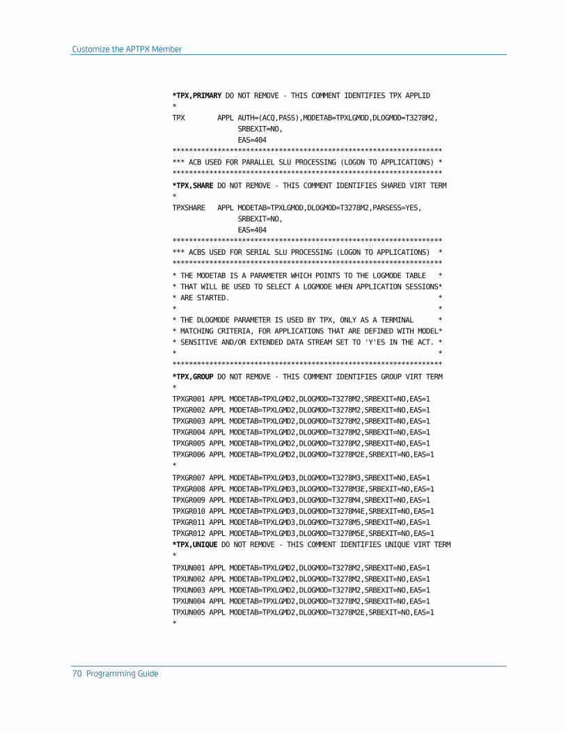
Customize the APTPX Member
70 Programming Guide
*TPX,PRIMARY DO NOT REMOVE - THIS COMMENT IDENTIFIES TPX APPLID
*
TPX APPL AUTH=(ACQ,PASS),MODETAB=TPXLGMOD,DLOGMOD=T3278M2,
SRBEXIT=NO,
EAS=404
******************************************************************
*** ACB USED FOR PARALLEL SLU PROCESSING (LOGON TO APPLICATIONS) *
******************************************************************
*TPX,SHARE DO NOT REMOVE - THIS COMMENT IDENTIFIES SHARED VIRT TERM
*
TPXSHARE APPL MODETAB=TPXLGMOD,DLOGMOD=T3278M2,PARSESS=YES,
SRBEXIT=NO,
EAS=404
******************************************************************
*** ACBS USED FOR SERIAL SLU PROCESSING (LOGON TO APPLICATIONS) *
******************************************************************
* THE MODETAB IS A PARAMETER WHICH POINTS TO THE LOGMODE TABLE *
* THAT WILL BE USED TO SELECT A LOGMODE WHEN APPLICATION SESSIONS*
* ARE STARTED. *
* *
* THE DLOGMODE PARAMETER IS USED BY TPX, ONLY AS A TERMINAL *
* MATCHING CRITERIA, FOR APPLICATIONS THAT ARE DEFINED WITH MODEL*
* SENSITIVE AND/OR EXTENDED DATA STREAM SET TO 'Y'ES IN THE ACT. *
* *
******************************************************************
*TPX,GROUP DO NOT REMOVE - THIS COMMENT IDENTIFIES GROUP VIRT TERM
*
TPXGR001 APPL MODETAB=TPXLGMD2,DLOGMOD=T3278M2,SRBEXIT=NO,EAS=1
TPXGR002 APPL MODETAB=TPXLGMD2,DLOGMOD=T3278M2,SRBEXIT=NO,EAS=1
TPXGR003 APPL MODETAB=TPXLGMD2,DLOGMOD=T3278M2,SRBEXIT=NO,EAS=1
TPXGR004 APPL MODETAB=TPXLGMD2,DLOGMOD=T3278M2,SRBEXIT=NO,EAS=1
TPXGR005 APPL MODETAB=TPXLGMD2,DLOGMOD=T3278M2,SRBEXIT=NO,EAS=1
TPXGR006 APPL MODETAB=TPXLGMD2,DLOGMOD=T3278M2E,SRBEXIT=NO,EAS=1
*
TPXGR007 APPL MODETAB=TPXLGMD3,DLOGMOD=T3278M3,SRBEXIT=NO,EAS=1
TPXGR008 APPL MODETAB=TPXLGMD3,DLOGMOD=T3278M3E,SRBEXIT=NO,EAS=1
TPXGR009 APPL MODETAB=TPXLGMD3,DLOGMOD=T3278M4,SRBEXIT=NO,EAS=1
TPXGR010 APPL MODETAB=TPXLGMD3,DLOGMOD=T3278M4E,SRBEXIT=NO,EAS=1
TPXGR011 APPL MODETAB=TPXLGMD3,DLOGMOD=T3278M5,SRBEXIT=NO,EAS=1
TPXGR012 APPL MODETAB=TPXLGMD3,DLOGMOD=T3278M5E,SRBEXIT=NO,EAS=1
*TPX,UNIQUE DO NOT REMOVE - THIS COMMENT IDENTIFIES UNIQUE VIRT TERM
*
TPXUN001 APPL MODETAB=TPXLGMD2,DLOGMOD=T3278M2,SRBEXIT=NO,EAS=1
TPXUN002 APPL MODETAB=TPXLGMD2,DLOGMOD=T3278M2,SRBEXIT=NO,EAS=1
TPXUN003 APPL MODETAB=TPXLGMD2,DLOGMOD=T3278M2,SRBEXIT=NO,EAS=1
TPXUN004 APPL MODETAB=TPXLGMD2,DLOGMOD=T3278M2,SRBEXIT=NO,EAS=1
TPXUN005 APPL MODETAB=TPXLGMD2,DLOGMOD=T3278M2E,SRBEXIT=NO,EAS=1
*
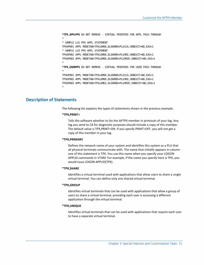
Customize the APTPX Member
Chapter 3: Special Features and Customization Tasks 71
*TPX,APPLPPS DO NOT REMOVE - VIRTUAL PRINTERS FOR APPL PASS-THROUGH
*
* SAMPLE LU1 PPS APPL STATEMENT
TPXAP001 APPL MODETAB=TPXLGMOD,DLOGMOD=PLU1CA,SRBEXIT=NO,EAS=1
* SAMPLE LU3 PPS APPL STATEMENT
TPXAP002 APPL MODETAB=TPXLGMOD,DLOGMOD=PLU3M2,SRBEXIT=NO,EAS=1
TPXAP003 APPL MODETAB=TPXLGMOD,DLOGMOD=PLU3M2E,SRBEXIT=NO,EAS=1
*
*TPX,USERPPS DO NOT REMOVE - VIRTUAL PRINTERS FOR USER PASS-THROUGH
*
TPXUP001 APPL MODETAB=TPXLGMOD,DLOGMOD=PLU1CA,SRBEXIT=NO,EAS=1
TPXUP002 APPL MODETAB=TPXLGMOD,DLOGMOD=PLU3M2,SRBEXIT=NO,EAS=1
TPXUP003 APPL MODETAB=TPXLGMD2,DLOGMOD=PLU3M2E,SRBEXIT=NO,EAS=1
*
Description of Statements
The following list explains the types of statements shown in the previous example.
*TPX,PRINT=
Tells the software whether to list the APTPX member in printouts of your log. Any log you send to CA for diagnostic purposes should include a copy of this member. The default value is TPX,PRINT=ON. If you specify PRINT=OFF, you will not get a copy of this member in your log.
*TPX,PRIMARY
Defines the network name of your system and identifies this system as a PLU that all physical terminals communicate with. The name that initially appears in column one of this statement is TPX. You use this name when you specify your LOGON APPLID commands in VTAM. For example, if the name you specify here is TPX, you would issue LOGON APPLID(TPX).
*TPX,SHARE
Identifies a virtual terminal used with applications that allow users to share a single virtual terminal. You can define only one shared virtual terminal.
*TPX,GROUP
Identifies virtual terminals that can be used with applications that allow a group of users to share a virtual terminal, providing each user is accessing a different application through the virtual terminal.
*TPX,UNIQUE
Identifies virtual terminals that can be used with applications that require each user to have a separate virtual terminal.
Customize the APTPX Member
72 Programming Guide
*TPX,APPLPPS
Identifies virtual printers used for Application Passthrough Printer Support. For more information about Application Passthrough Printer Support, see the Administration Guide.
*TPX,USERPPS
Identifies virtual printers used for User Passthrough Printer Support. For more information about User Passthrough Printer Support, see the Administration Guide.
Note: If you specify PASS access at the system level, the product does not use virtual terminals, and the statements beneath the TPX,SHARE, TPX,GROUP, and TPX,UNIQUE comments are ignored.
Application Definition Parameters
The following list explains the parameters on the application definition statements in the previous example.
PARSESS
Specifies whether users can share this virtual terminal. You must include this parameter in the statement defining a virtual terminal. To allow users to share the virtual terminal for applications allowing parallel sessions, specify YES.
SRBEXIT (z/OS only)
Determines whether the product uses the VTAM authorized path facility (also called "fast path"). You must include this parameter on each statement in the APTPX member. Initially, the SRBEXIT parameter in each statement is set to NO for ease of installation.
To use the authorized path facility
1. Change the value of each SRBEXIT parameter to YES.
2. Put the load modules in an APF-authorized library, as described in the Installation Guide.
3. Enter a Y in the VTAM Authorized Path Facility field of the performance parameters panel on the System Options Table (SMRT).
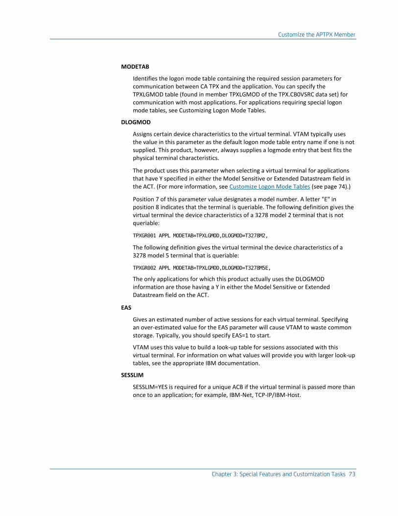
Customize the APTPX Member
Chapter 3: Special Features and Customization Tasks 73
MODETAB
Identifies the logon mode table containing the required session parameters for communication between CA TPX and the application. You can specify the TPXLGMOD table (found in member TPXLGMOD of the TPX.CB0VSRC data set) for communication with most applications. For applications requiring special logon mode tables, see Customizing Logon Mode Tables.
DLOGMOD
Assigns certain device characteristics to the virtual terminal. VTAM typically uses the value in this parameter as the default logon mode table entry name if one is not supplied. This product, however, always supplies a logmode entry that best fits the physical terminal characteristics.
The product uses this parameter when selecting a virtual terminal for applications that have Y specified in either the Model Sensitive or Extended Datastream field in the ACT. (For more information, see Customize Logon Mode Tables (see page 74).)
Position 7 of this parameter value designates a model number. A letter "E" in position 8 indicates that the terminal is queriable. The following definition gives the virtual terminal the device characteristics of a 3278 model 2 terminal that is not queriable:
TPXGR001 APPL MODETAB=TPXLGMOD,DLOGMOD=T3278M2,
The following definition gives the virtual terminal the device characteristics of a 3278 model 5 terminal that is queriable:
TPXGR002 APPL MODETAB=TPXLGMOD,DLOGMOD=T3278M5E,
The only applications for which this product actually uses the DLOGMOD information are those having a Y in either the Model Sensitive or Extended Datastream field on the ACT.
EAS
Gives an estimated number of active sessions for each virtual terminal. Specifying an over-estimated value for the EAS parameter will cause VTAM to waste common storage. Typically, you should specify EAS=1 to start.
VTAM uses this value to build a look-up table for sessions associated with this virtual terminal. For information on what values will provide you with larger look-up tables, see the appropriate IBM documentation.
SESSLIM
SESSLIM=YES is required for a unique ACB if the virtual terminal is passed more than once to an application; for example, IBM-Net, TCP-IP/IBM-Host.

Customize Logon Mode Tables
74 Programming Guide
Customize Logon Mode Tables
At the time a physical terminal is logged on, CA TPX receives information about the terminal characteristics from one of the following sources:
■ An entry on the logon mode table defined in SYS1.VTAMLST (VTAM major node definition in VM) for the physical terminal
■ The response to a query from this product to the physical terminal
Using this information, this product identifies the model of the terminal (2, 3, 4, or 5) and whether the terminal is queriable.
When the user of the physical terminal starts a virtual terminal session, this product checks the virtual terminal definition for the logon mode table. It then passes an entry from this table to establish session parameters. It chooses an entry that matches the physical terminal type, model number, and that can or cannot be queried, depending on the physical terminal.
Entries that are not queriable have this format:
T327XMn
Entries that are queriable have this format:
T327XMnE
Value Explanation
X Terminal type (8 or 9)
Mn Model number (M2, M3, M4, or M5)
E Terminal is queriable
To supply the product with these entries, you must specify logon mode tables on your virtual terminal definitions in SYS1.VTAMLST. You specify the table with the MODETAB parameter.
Note: You do not need logon mode tables if you have defined PASS access for this product.
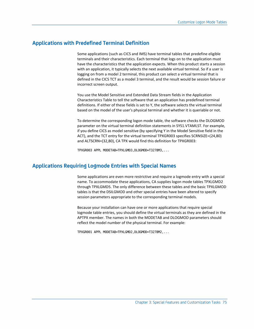
Customize Logon Mode Tables
Chapter 3: Special Features and Customization Tasks 75
Applications with Predefined Terminal Definition
Some applications (such as CICS and IMS) have terminal tables that predefine eligible terminals and their characteristics. Each terminal that logs on to the application must have the characteristics that the application expects. When this product starts a session with an application, it typically selects the next available virtual terminal. So if a user is logging on from a model 2 terminal, this product can select a virtual terminal that is defined in the CICS TCT as a model 3 terminal, and the result would be session failure or incorrect screen output.
You use the Model Sensitive and Extended Data Stream fields in the Application Characteristics Table to tell the software that an application has predefined terminal definitions. If either of these fields is set to Y, the software selects the virtual terminal based on the model of the user's physical terminal and whether it is queriable or not.
To determine the corresponding logon mode table, the software checks the DLOGMOD parameter on the virtual terminal definition statements in SYS1.VTAMLST. For example, if you define CICS as model sensitive (by specifying Y in the Model Sensitive field in the ACT), and the TCT entry for the virtual terminal TPXGR003 specifies SCRNSIZE=(24,80) and ALTSCRN=(32,80), CA TPX would find this definition for TPXGR003:
TPXGR003 APPL MODETAB=TPXLGMD3,DLOGMOD=T3278M3,...
Applications Requiring Logmode Entries with Special Names
Some applications are even more restrictive and require a logmode entry with a special name. To accommodate these applications, CA supplies logon mode tables TPXLGMD2 through TPXLGMD5. The only difference between these tables and the basic TPXLGMOD tables is that the DSILGMOD and other special entries have been altered to specify session parameters appropriate to the corresponding terminal models.
Because your installation can have one or more applications that require special logmode table entries, you should define the virtual terminals as they are defined in the APTPX member. The names in both the MODETAB and DLOGMOD parameters should reflect the model number of the physical terminal. For example:
TPXGR001 APPL MODETAB=TPXLGMD2,DLOGMOD=T3278M2,...
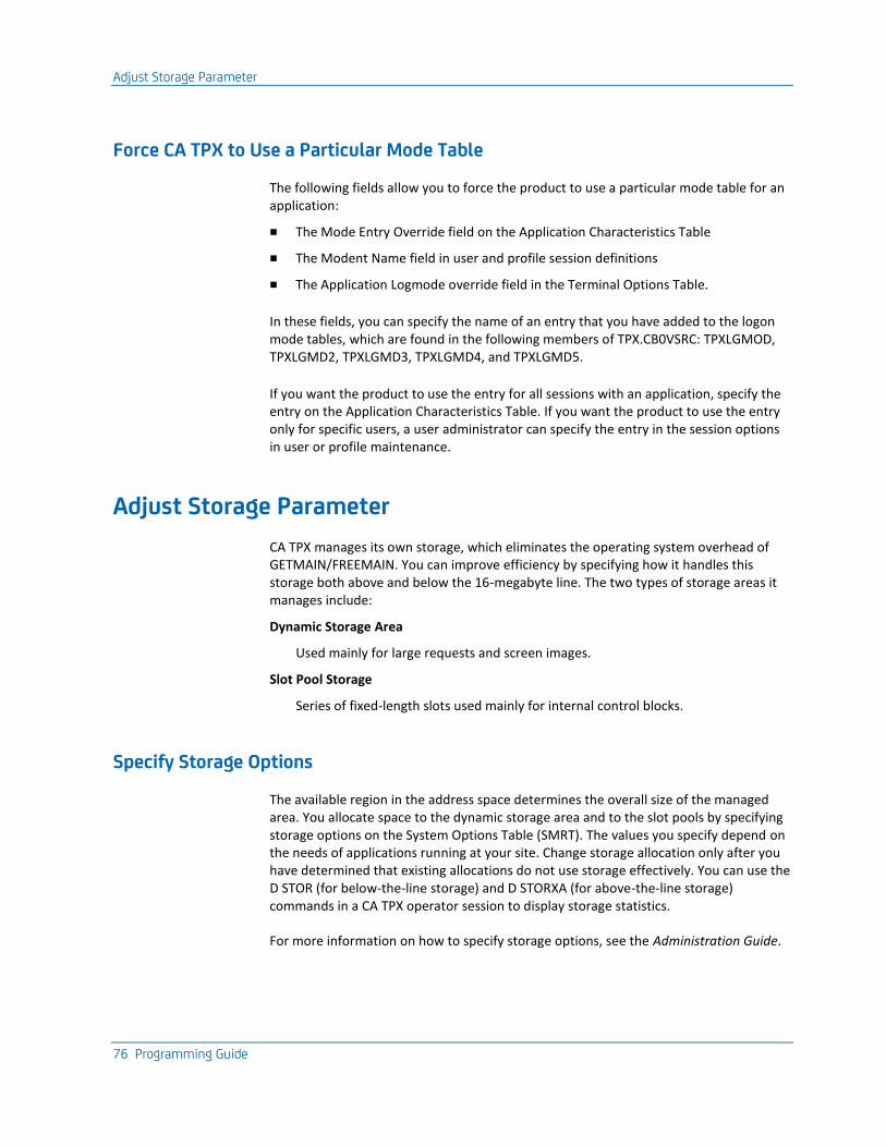
Adjust Storage Parameter
76 Programming Guide
Force CA TPX to Use a Particular Mode Table
The following fields allow you to force the product to use a particular mode table for an application:
■ The Mode Entry Override field on the Application Characteristics Table
■ The Modent Name field in user and profile session definitions
■ The Application Logmode override field in the Terminal Options Table.
In these fields, you can specify the name of an entry that you have added to the logon mode tables, which are found in the following members of TPX.CB0VSRC: TPXLGMOD, TPXLGMD2, TPXLGMD3, TPXLGMD4, and TPXLGMD5.
If you want the product to use the entry for all sessions with an application, specify the entry on the Application Characteristics Table. If you want the product to use the entry only for specific users, a user administrator can specify the entry in the session options in user or profile maintenance.
Adjust Storage Parameter
CA TPX manages its own storage, which eliminates the operating system overhead of GETMAIN/FREEMAIN. You can improve efficiency by specifying how it handles this storage both above and below the 16-megabyte line. The two types of storage areas it manages include:
Dynamic Storage Area
Used mainly for large requests and screen images.
Slot Pool Storage
Series of fixed-length slots used mainly for internal control blocks.
Specify Storage Options
The available region in the address space determines the overall size of the managed area. You allocate space to the dynamic storage area and to the slot pools by specifying storage options on the System Options Table (SMRT). The values you specify depend on the needs of applications running at your site. Change storage allocation only after you have determined that existing allocations do not use storage effectively. You can use the D STOR (for below-the-line storage) and D STORXA (for above-the-line storage) commands in a CA TPX operator session to display storage statistics.
For more information on how to specify storage options, see the Administration Guide.

Adjust Storage Parameter
Chapter 3: Special Features and Customization Tasks 77
How CA TPX Responds to Storage Requests
Most components request storage from an appropriate slot pool either above or below the 16-MB line. Using slot pools prevents storage fragmentation that can occur with other storage management techniques. When this product receives a storage allocation request, it attempts to use the smallest slot poolsize to satisfy the request. If that slot pool is fully allocated, it uses the next slot pool.
This product converts the request to a dynamic storage area (DSA) request and allocates the appropriate amount of storage from the DSA if one of the following conditions occurs:
■ More than two slots pools have failed to satisfy the request.
■ The request is for an amount larger than the largest slot pool.
Display Storage Statistics
Before you adjust the storage allocation parameters, you need to see how this product is handling allocation requests. To display below-the-line storage statistics, issue this command from an operator session:
D STOR
To display above-the-line storage statistics, issue this command from an operator session:
D STORXA
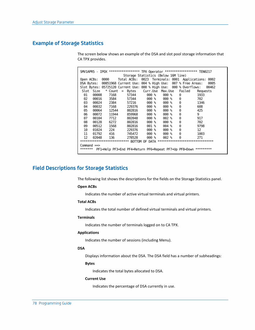
Adjust Storage Parameter
78 Programming Guide
Example of Storage Statistics
The screen below shows an example of the DSA and slot pool storage information that CA TPX provides.
SMV1APR5 - IPOX ***************** TPX Operator ****************** TEN0217 Storage Statistics (Below 16M line) Open ACBs: 0000 Total ACBs: 0023 Terminals: 0001 Applications: 0002 DSA Bytes: 00851968 Current Use: 004 % High Use: 007 % Free Areas: 0005 Slot Bytes: 05725120 Current Use: 000 % High Use: 000 % Overflows: 00462 Slot Size * Count = Bytes Curr.Use Max.Use Failed Requests 01 00008 7168 57344 000 % 000 % 0 1933 02 00016 3584 57344 000 % 000 % 0 702 03 00024 2384 57216 000 % 000 % 0 1346 04 00032 7168 229376 000 % 000 % 0 608 05 00064 12544 802816 000 % 000 % 0 425 06 00072 11944 859968 000 % 000 % 0 9 07 00104 7712 802048 000 % 002 % 0 917 08 00128 6272 802816 000 % 000 % 0 702 09 00512 1568 802816 001 % 004 % 0 9798 10 01024 224 229376 000 % 000 % 0 12 11 01792 416 745472 000 % 000 % 0 1003 12 02048 136 278528 000 % 002 % 0 271 *************************** BOTTOM OF DATA ******************************* Command ==> ******* PF1=Help PF3=End PF4=Return PF6=Repeat PF7=Up PF8=Down *********
Field Descriptions for Storage Statistics
The following list shows the descriptions for the fields on the Storage Statistics panel.
Open ACBs
Indicates the number of active virtual terminals and virtual printers.
Total ACBs
Indicates the total number of defined virtual terminals and virtual printers.
Terminals
Indicates the number of terminals logged on to CA TPX.
Applications
Indicates the number of sessions (including Menu).
DSA
Displays information about the DSA. The DSA field has a number of subheadings:
Bytes
Indicates the total bytes allocated to DSA.
Current Use
Indicates the percentage of DSA currently in use.
Adjust Storage Parameter
Chapter 3: Special Features and Customization Tasks 79
High Use
Indicates the maximum percentage of DSA used.
Free Areas
Indicates the number of fragments of free space in DSA.
Slot
Displays information about the fixed length slot pools. The slot field has a number of subheadings:
Bytes
Indicates the total bytes allocated to slot pools.
Current Use
Indicates the percentage of slot pools currently in use.
High Use
Indicates the maximum percentage of slot pools used.
Overflows
Indicates the number of slot pool requests that DSA handled because slot pool 12 was full or request was larger than any slot pool.
Slot Table
Summarizes memory usage in the slot pools. The following subheadings appear in the slot table:
Slot
Indicates the slot pool number.
Size
Indicates the size of slot entry in bytes.
Count
Indicates the number of slot pools of this size.
Bytes
Indicates the total storage in slot pool.
Curr.Use
Indicates the current percentage of slot in use.
Max.Use
Indicates the maximum percentage of slot used.
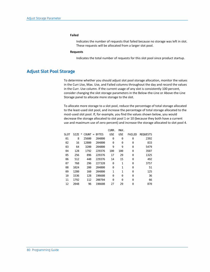
Adjust Storage Parameter
80 Programming Guide
Failed
Indicates the number of requests that failed because no storage was left in slot. These requests will be allocated from a larger slot pool.
Requests
Indicates the total number of requests for this slot pool since product startup.
Adjust Slot Pool Storage
To determine whether you should adjust slot pool storage allocation, monitor the values in the Curr.Use, Max. Use, and Failed columns throughout the day and record the values in the Curr. Use column. If the current usage of any slot is consistently 100 percent, consider changing the slot storage parameters in the Below-the-Line or Above-the-Line Storage panel to allocate more storage to the slot.
To allocate more storage to a slot pool, reduce the percentage of total storage allocated to the least-used slot pool, and increase the percentage of total storage allocated to the most-used slot pool. If, for example, you find the values shown below, you would decrease the storage allocated to slot pool 1 or 10 (because they both have a current use and maximum use of zero percent) and increase the storage allocated to slot pool 4.
CURR. MAX.
SLOT SIZE * COUNT = BYTES USE USE FAILED REQUESTS
01 8 25600 204800 0 0 0 2392
02 16 12800 204800 0 0 0 833
03 64 3200 204800 9 9 0 5479
04 128 1792 229376 100 100 0 3507
05 256 896 229376 17 29 0 1325
06 512 448 229376 14 15 0 492
07 768 296 227328 0 1 0 3757
08 1024 200 204800 0 1 0 51
09 1280 160 204800 1 1 0 125
10 1536 128 196608 0 0 0 36
11 1792 112 200704 0 0 0 66
12 2048 96 196608 27 29 0 870
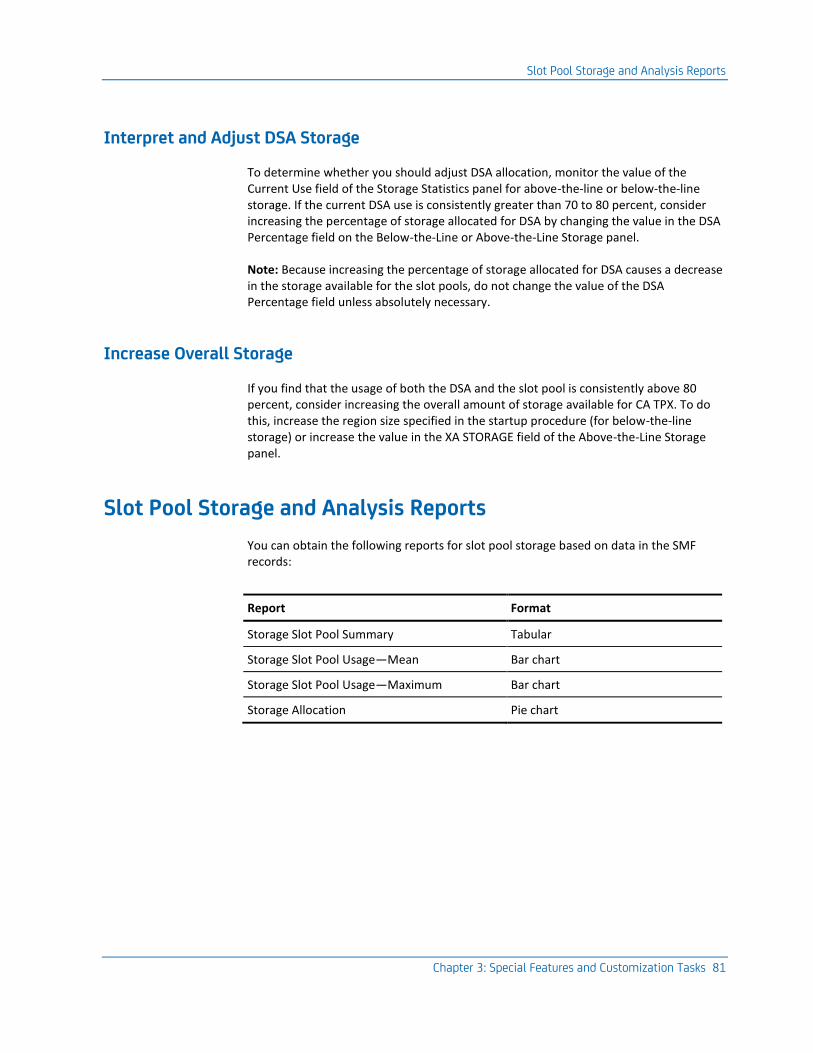
Slot Pool Storage and Analysis Reports
Chapter 3: Special Features and Customization Tasks 81
Interpret and Adjust DSA Storage
To determine whether you should adjust DSA allocation, monitor the value of the Current Use field of the Storage Statistics panel for above-the-line or below-the-line storage. If the current DSA use is consistently greater than 70 to 80 percent, consider increasing the percentage of storage allocated for DSA by changing the value in the DSA Percentage field on the Below-the-Line or Above-the-Line Storage panel.
Note: Because increasing the percentage of storage allocated for DSA causes a decrease in the storage available for the slot pools, do not change the value of the DSA Percentage field unless absolutely necessary.
Increase Overall Storage
If you find that the usage of both the DSA and the slot pool is consistently above 80 percent, consider increasing the overall amount of storage available for CA TPX. To do this, increase the region size specified in the startup procedure (for below-the-line storage) or increase the value in the XA STORAGE field of the Above-the-Line Storage panel.
Slot Pool Storage and Analysis Reports
You can obtain the following reports for slot pool storage based on data in the SMF records:
Report Format
Storage Slot Pool Summary Tabular
Storage Slot Pool Usage—Mean Bar chart
Storage Slot Pool Usage—Maximum Bar chart
Storage Allocation Pie chart
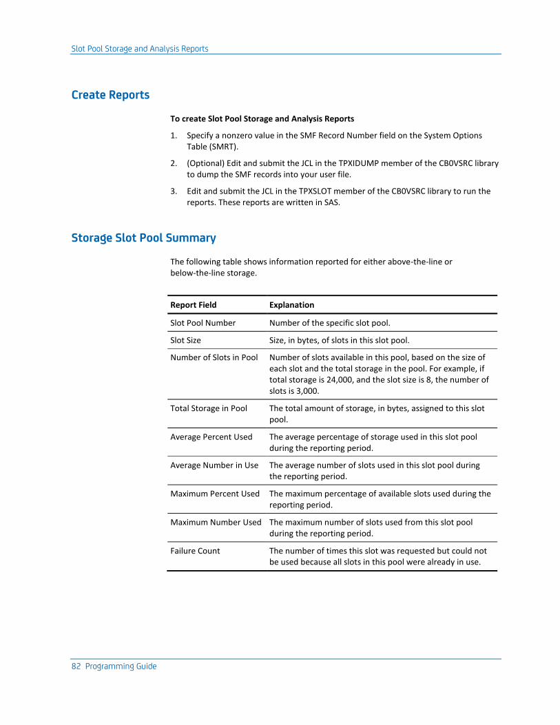
Slot Pool Storage and Analysis Reports
82 Programming Guide
Create Reports
To create Slot Pool Storage and Analysis Reports
1. Specify a nonzero value in the SMF Record Number field on the System Options Table (SMRT).
2. (Optional) Edit and submit the JCL in the TPXIDUMP member of the CB0VSRC library to dump the SMF records into your user file.
3. Edit and submit the JCL in the TPXSLOT member of the CB0VSRC library to run the reports. These reports are written in SAS.
Storage Slot Pool Summary
The following table shows information reported for either above-the-line or below-the-line storage.
Report Field Explanation
Slot Pool Number Number of the specific slot pool.
Slot Size Size, in bytes, of slots in this slot pool.
Number of Slots in Pool Number of slots available in this pool, based on the size of each slot and the total storage in the pool. For example, if total storage is 24,000, and the slot size is 8, the number of slots is 3,000.
Total Storage in Pool The total amount of storage, in bytes, assigned to this slot pool.
Average Percent Used The average percentage of storage used in this slot pool during the reporting period.
Average Number in Use The average number of slots used in this slot pool during the reporting period.
Maximum Percent Used The maximum percentage of available slots used during the reporting period.
Maximum Number Used The maximum number of slots used from this slot pool during the reporting period.
Failure Count The number of times this slot was requested but could not be used because all slots in this pool were already in use.

Slot Pool Storage and Analysis Reports
Chapter 3: Special Features and Customization Tasks 83
Slot Pool Usage—Mean
The following table shows information reported for Storage Slot Pool Usage—Mean for either above-the-line or below-the-line storage.
Report Field Explanation
SLOTNR Number of the specific slot pool.
PCTUSED MEAN (bottom line)
The average percentage of total slot-pool storage used in this particular slot pool during the reporting period.
FREQ The number of observations used in calculating the values reported.
PCTUSED MEAN (right column)
The average percentage of storage used in this slot pool during the reporting period.
Slot Pool Usage
The following table shows information reported for Slot Pool Usage—Maximum for either above-the-line or below-the-line storage.
Report Field Explanation
SLOTNR Number of the specific slot pool.
MAXPCT (bottom line) The maximum percentage of total slot-pool storage used in this particular slot pool during the reporting period.
MAXPCT (right column) The maximum amount of storage used in this slot pool during the reporting period.

Mail Facility
84 Programming Guide
Storage Allocation
Storage Allocation pie charts show how storage is divided among the slot pools. The following chart shows a sample report with each pie slice representing a slot number.
Mail Facility
The Mail facility allows users to send messages to other CA TPX users. Usually, these messages appear on the user's terminal when the user presses an AID key.
If your site is authorized for the MAIL file, users can also send messages directly to other users' mailboxes, so that users can review the message the next time they check their mailbox. You can also maintain user lists to easily send messages to a specific group of users.
With the mail facility, users can specify message recipients not only by user IDs, but through a wide variety of methods, such as users of a specific application, or terminal, or session, and so on.

Mail Facility
Chapter 3: Special Features and Customization Tasks 85
Command Authorization
The user administrator can control which features of the mail facility users can select. When a user displays the Mail Menu panel, if an option is not highlighted, the user is not allowed to use it.
Command authorization is maintained with online administration, in the Command Authorization Class option under User/Group Maintenance. For information on maintaining command authorization classes online, see the Administration Guide.
Userlists
Users can, if authorized, create and maintain userlists in the mail facility. By creating your own personal userlists, or using public userlists, you can send a single message to a group of users simultaneously.
The userlists can contain not only lists of user IDs, but also lists of terminal IDs, application names, or any other type of identifier that can be used to specify mail recipients. This allows users to easily send messages to specific groups of users.
There are three types of userlists, as described in the following table:
Type of Userlist Description
General ■ Created or modified by any system administrator.
■ Can be used by any user.
■ The creator can specify that users cannot browse or copy the contents of the list.
Group ■ Owned by a user group.
■ Can be created or edited by any user administrator who is authorized to administer the user group that owns the list.
■ Can always be used, browsed, and copied by members of the user group.
■ The creator can specify that users outside the user group cannot use and/or browse and copy the contents of the list.
Personal ■ Created or modified by a single user.
■ The creator can specify that other users cannot use and/or browse and copy the contents of the list.
View Facility
86 Programming Guide
Mail Functions with the Batch Facility
The batch administration facility can be used to send and delete mail messages. For information on performing mail functions with the batch facility, see the Batch Administration Guide.
With the batch facility, the administrator can also purge expired mail messages.
Mail Locators
Mail locators create an association between a mail message text and the users who have that message in their mailbox. The message text exists once, but has a mail locator for each user's mailbox that contains the message. The mail locators are maintained in the VSAM file named MAIL. Mail messages are also maintained in that file.
Mail locators can be extracted and deleted using the batch administration facility. For information on performing mail functions with the batch facility, see the Batch Administration Guide.
View Facility
The View facility consists of a number of features that allow users on the same instance of CA TPX to view another user's application session and sometimes interact with that session. Users can also record sessions and can play back the recorded sessions. All of these features are accessed through the TPXVIEW session.
For more information, see the View Facility User Guide. Online help is available throughout the facility.
View Facility Security
The View facility is secured by two methods, both of which are implemented by the user administrator through online administration.
■ The View authority level and security level, that control which user's sessions you can view, track, or assist, and which users can view, track, or assist your sessions. The authority level and security level are maintained online in user maintenance.
■ The command authorization classes, which control the View options a user can use. The command authorization classes also control what commands a user can use.
For descriptions of command authorization classes, see the Administration Guide.
For a summary of the tasks required to ensure secure operation of the View facility, see the User Guide.

Control Application Sessions with OPENGATE
Chapter 3: Special Features and Customization Tasks 87
View Is an Authorized Feature
The View facility is an authorized feature of CA TPX. Your site must be authorized to use it. However, you can use the View facility on internal sessions without needing a site license. You can use any of the View features on the internal sessions: TPXADMIN, TPXOPER, TPXNOTES, or TPXMAIL.
Control Application Sessions with OPENGATE
OPENGATE allows you to perform the pre-session setup and/or post-session cleanup required for some application sessions. When a user starts a session controlled by OPENGATE, a control ACL/E program is scheduled to perform the pre-session setup after the product assigns the virtual terminal for that session. When a session controlled by OPENGATE ends, the control ACL/E program is scheduled to perform post-session cleanup before CA TPX frees the virtual terminal. The user is never aware that OPENGATE is controlling the session.
Example
An installation can re-assign the IMS LTERM (the logical terminal normally assigned to the user's physical terminal) to the virtual terminal assigned by the product. When a user starts an IMS session, OPENGATE suspends activity immediately after the virtual terminal is assigned. It then schedules a control ACL program on an IMS control user's session. The user's IMS session proceeds when the control ACL program terminates. When a user terminates a session, OPENGATE re-assigns the LTERM back to the user's physical terminal.
Setting Up OPENGATE
To set up OPENGATE to control an application session
1. Create the control ACL program.
2. Build a control user by:
■ Defining the control user to CA TPX
■ Defining the application sessions for the control user
■ Creating and defining the startup ACL program for the application sessions
3. Update the ACT definition for the controlled application by specifying the control user for that application.

Control Application Sessions with OPENGATE
88 Programming Guide
Create Control ACL/E Programs
When a user initiates a session to a controlled application, OPENGATE schedules a control ACL on one of the control user's application sessions. The ACL program performs the session setup or cleanup activity for the application. Because the session setup/cleanup activity is unique to each installation, you must create the control ACL program. (For information on creating ACL programs, see the ACL/E Programming Guide.)
Variables Used in
To specify information to your control ACL program, use the following variables:
ZPCODE
Indicates the status of the virtual terminal (ACB) call. This variable has a value of ASSIGN when the session is initiated and a value of FREE when the session is terminated.
ZPUID
Indicates the user ID of the user who is activating the session.
ZPSID
Indicates the session ID of the requested session.
ZPACB
Indicates the name of the allocated virtual terminal.
ZPTERM
Indicates the ID of the requester's physical terminal.
ZPAPPL
Indicates the application ID for the session.
You should write the ACL program to detect any unusual situations and set the variables ZPRTCDE and ZPFDBK with your own error code and message.
ZPRTCDE
A 1-to-8 character return code (non-blank=failure).
ZPFDBK
A 1-to-64 character message describing the error.
If values are assigned to these variables during the execution of the control ACL program, panel TEN0056 is displayed, informing the user starting the application session of the error. This panel is not displayed if ZPRTCDE is set to NODISP.
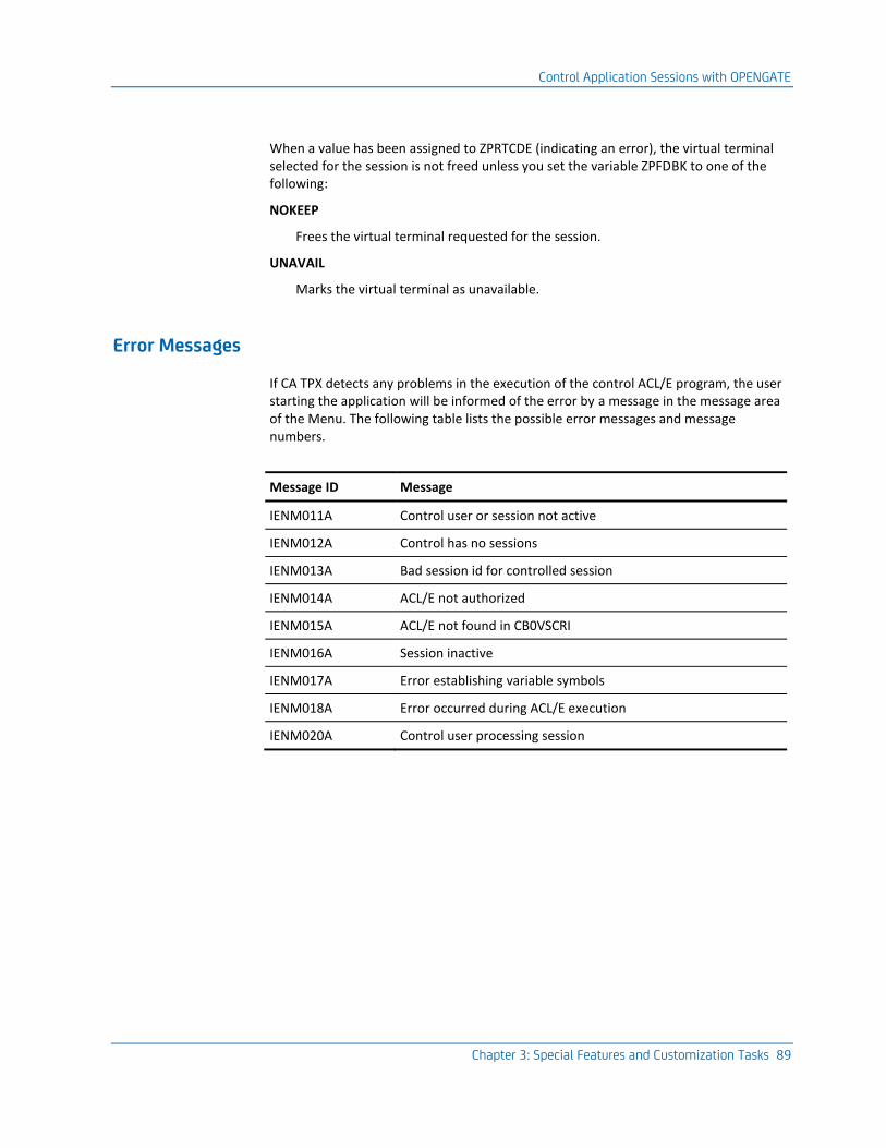
Control Application Sessions with OPENGATE
Chapter 3: Special Features and Customization Tasks 89
When a value has been assigned to ZPRTCDE (indicating an error), the virtual terminal selected for the session is not freed unless you set the variable ZPFDBK to one of the following:
NOKEEP
Frees the virtual terminal requested for the session.
UNAVAIL
Marks the virtual terminal as unavailable.
Error Messages
If CA TPX detects any problems in the execution of the control ACL/E program, the user starting the application will be informed of the error by a message in the message area of the Menu. The following table lists the possible error messages and message numbers.
Message ID Message
IENM011A Control user or session not active
IENM012A Control has no sessions
IENM013A Bad session id for controlled session
IENM014A ACL/E not authorized
IENM015A ACL/E not found in CB0VSCRI
IENM016A Session inactive
IENM017A Error establishing variable symbols
IENM018A Error occurred during ACL/E execution
IENM020A Control user processing session
Control Application Sessions with OPENGATE
90 Programming Guide
Build Control Users
To build a control user for an application controlled by OPENGATE
Note: You define a control user as you would any other user. For more information, see the Administration Guide. You must use a defined, not dynamic, control user ID for OPENGATE.
1. Create the control user ID:
a. Specify a user ID identical to the name of your control ACL/E program for the application.
b. Specify NONE in the Security system field on the Userid Maintenance Detail Panel.
c. Specify NONE in the Transfer option field on the Userid Maintenance Detail Panel.
2. Define a session for the controlled application:
a. Access the Userid Maintenance Table Entry List and define a session for the application.
Note: If multiple users will be starting and/or ending sessions concurrently to the controlled application, you can define additional sessions for the application to handle the concurrent session setup/cleanup activity. If a user tries to access the application while all of the control user's sessions are busy, the control ACL/E program will be scheduled on the session that has been processing for the longest amount of time (the session that should free up first).
b. Access the Userid Maintenance Detail Panel and enter Y in the Start at signon field. This causes the session to start automatically when the control user is signed on to CA TPX.
3. Create and define a startup ACL/E program for the session:
a. Create a startup ACL/E program to perform initialization on the application before session setup and/or cleanup occurs (for example, signing on to IMS).
Note: The startup ACL/E program is not the same as the control ACL/E program. A startup ACL/E program is necessary only if the application requires initialization before session setup and/or cleanup activity can be performed.
b. Enter the name of the program in the Startup ACL field on the Userid Maintenance Detail Panel.
Advanced Data Compression
Chapter 3: Special Features and Customization Tasks 91
Update ACT
You must update the ACT so the product will sign the control user on at startup.
1. Access the Application Characteristics Detail panel. For more information, see the Administration Guide.
2. Type the control user ID in the OPENGATE Control User field.
The next time you restart the product, the control user will be signed on automatically.
Note: At this point, the name of the control ACL/E program, the control user ID, and the ID specified in the OPENGATE Control User field should be identical.
Advanced Data Compression
Using Advanced Data Compression (ADC), you can compress inbound and outbound data in your network. This process reduces network traffic and shortens inbound and outbound queuing times, which results in improved end-user response time. If data is already optimal in length, ADC ignores the data to conserve resources.
ADC also allows you to strip an application's extended attribute bytes from the data stream when they are not supported by the physical terminal.
Note: You must have the proper authorization code to use ADC.
Inbound Data Compression
Inbound compression affects data streams sent from the terminal to the application. It reduces the amount of data transmitted inbound by turning off preset Modified Data Tags (MDTs) before sending fields of data to the terminal.
The MDT resides in each field attribute byte in the terminal controller. When a user modifies a field (for example, typing data), this bit is set on. Some host applications set this bit on before sending the attribute bytes to the terminal, which causes data in the field to be transmitted to the application whenever the user presses Enter or another action key. This results in data being returned from the screen even if it has not been altered. Although presetting the MDT on can be convenient for an application, it increases transmission time and wastes resources.
When you turn inbound compression on, the software remembers which fields were preset with MDTs and removes the MDT bit from the data going to the terminal. When the data is sent back from the terminal, the product combines the inbound data with any preset MDTs before passing the data to the host application.
Advanced Data Compression
92 Programming Guide
Outbound Data Compression
Outbound compression affects data streams sent from the application to the terminal. It reduces the amount of data transmitted outbound by eliminating repeated characters and unnecessary Set Buffer Address orders from the data stream.
CA TPX checks the outbound data stream for characters that are repeated over four times in sequence. It shortens this repetition to four characters with the Repeat-to-Address order.
A 3270 Set Buffer Address order is unnecessary when the last data character in the outbound data stream is currently at the address set by this order. In this case, the software would eliminate the Set Buffer Address order.
This product samples each outbound data stream to see if it should be compressed. If 16 consecutive data streams do not need compressed, compression is turned off for the next 16 data streams. The sampling process then resumes with the next data stream.
Function of Outbound Stripping
If you request outbound stripping for an application, the product strips out extended attributes that are not supported by the physical terminal. This feature is useful if you have applications that send extended attribute bytes to a terminal without first determining if the terminal supports them. It allows you to transfer a session from a terminal that supports extended attribute bytes to a terminal that does not support them. Without outbound stripping, these two sessions would be incompatible.
Turning on Compression
To compress outbound and/or inbound data for an application, specify Y in the Outbound Compression and/or Inbound Compression field on the ACT.
You can override the values you specify in the ACT on the Terminal Options Detail panel of the Terminal Options Table. Specify Y or N in the following fields to override existing values:
■ Override ACT, Outbound Compression On
■ Override ACT, Outbound Compression Off
■ Override ACT, Inbound Compression On
■ Override ACT, Inbound Compression Off
Implement Tiered Menus
Chapter 3: Special Features and Customization Tasks 93
Turning on Outbound Stripping
To turn on outbound stripping for an application, specify Y in the Outbound stripping field on the Application Characteristics Table.
Display Compression Statistics
You can issue the DISPLAY command in an operator session to show the following session information. This information reflects the data that is actually compressed.
■ Number of inbound and outbound messages
■ Number of inbound and outbound messages using compression
■ Average number of characters per inbound or outbound message
■ Percentage of savings from compression
■ Average number of characters per message entering outbound compression
■ Average number of characters sent from the terminal with inbound compression
■ Total number of characters sent to the application with inbound compression
■ Average number of characters per message after outbound compression
Format of the Command
To show statistics for all sessions, specify D STATS,ALL.
To show statistics for statistics for a specific user, specify D STATS,U=userID.
Implement Tiered Menus
CA TPX r5.3 supports the use of tiered menus. You can define tiered menu entries either online or with batch administration. The session definitions are used to identify a tier and connect the sessions of the subsequent menu to that identity.
The literal TPXTIERx (where x can be 0 through z) in the Applid/Tier LVL field indicates that this session is a tiered menu entry.
Note: For more information about the use of online administration, see the Administration Guide. For more information about the use of batch administration, see the Batch Administration Guide.

Implement Tiered Menus
94 Programming Guide
Example of a Tiered Menu Design
A company needs to present three entries for the primary menu that lead to sub menus (TSO, CICS, and SYSPROG) and application session entries for TPXOPER, TPXVIEW, and AUDIT. If the menu design is correct, it will appear as the following screen:
TPX MENU FOR TPXUSER1 Panelid - TEN0041 Terminal - A11BU002 Cmdkey=PF12/24 Jump=NONE Menu=PF4 Model - 3278-5A Print=NONE Cmdchar=\ System - TPXPROD Sessid Sesskey Session Description Status _ TSO PF TSO Menu _ CICS PF CICS Menu _ SYSPROG PF System Programmer Menu _ TPXOPER PF TPX OPERATOR _ TPXVIEW PF TPX VIEW Application _ AUDIT PF Corporate Auditing Command ===> PF1=Help PF7/19=Up PF8/20=Down PF10/22=Left PF11/23=Right H =Cmd Help
TPXOPER, TPXVIEW, and AUDIT are actual applications and selecting any of these would start a session to the respective application.

Implement Tiered Menus
Chapter 3: Special Features and Customization Tasks 95
From the main menu, the user can also complete the following actions:
■ When the user selects TSO, the following menu will be displayed:
TPX MENU FOR TPXUSER1 Panelid - TEN0041 Terminal - A11BU002 Cmdkey=PF12/24 Jump=NONE Menu=PF4 Model - 3278-5A Print=NONE Cmdchar=\ System - TPXPROD Sessid Sesskey Session Description Status _ TSO1 PF TSO on System 1 _ TSO2 PF TSO on System 2 _ TSO3 PF TSO on System 3 _ RETURN PF Return to Prior Menu Command ===> PF1=Help PF7/19=Up PF8/20=Down PF10/22=Left PF11/23=Right H =Cmd Help
From the preceding screen, the user can select a TSO application session to start TSO1, TSO2, or TSO3. To return to the prior level menu, the user can select RETURN.
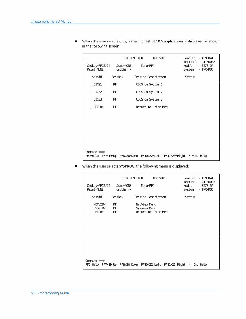
Implement Tiered Menus
96 Programming Guide
■ When the user selects CICS, a menu or list of CICS applications is displayed as shown in the following screen:
TPX MENU FOR TPXUSER1 Panelid - TEN0041 Terminal - A11BU002 Cmdkey=PF12/24 Jump=NONE Menu=PF4 Model - 3278-5A Print=NONE Cmdchar=\ System - TPXPROD Sessid Sesskey Session Description Status _ CICS1 PF CICS on System 1 _ CICS2 PF CICS on System 2 _ CICS3 PF CICS on System 3 _ RETURN PF Return to Prior Menu Command ===> PF1=Help PF7/19=Up PF8/20=Down PF10/22=Left PF11/23=Right H =Cmd Help
■ When the user selects SYSPROG, the following menu is displayed:
TPX MENU FOR TPXUSER1 Panelid - TEN0041 Terminal - A11BU002 Cmdkey=PF12/24 Jump=NONE Menu=PF4 Model - 3278-5A Print=NONE Cmdchar=\ System - TPXPROD Sessid Sesskey Session Description Status _ NETVIEW PF NetView Menu _ SYSVIEW PF Sysview Menu _ RETURN PF Return to Prior Menu Command ===> PF1=Help PF7/19=Up PF8/20=Down PF10/22=Left PF11/23=Right H =Cmd Help

Implement Tiered Menus
Chapter 3: Special Features and Customization Tasks 97
Here, NETVIEW and SYSVIEW are another level of tiered menus. If NETVIEW is selected, the following menu is displayed:
TPX MENU FOR TPXUSER1 Panelid - TEN0041 Terminal - A11BU002 Cmdkey=PF12/24 Jump=NONE Menu=PF4 Model - 3278-5A Print=NONE Cmdchar=\ System - TPXPROD Sessid Sesskey Session Description Status _ NETVIEW1 PF NetView on System 1 _ NETVIEW2 PF NetView on System 2 _ NETVIEW3 PF NetView on System 3 _ RETURN PF Return to Prior Menu Command ===> PF1=Help PF7/19=Up PF8/20=Down PF10/22=Left PF11/23=Right H =Cmd Help
And, if SYSVIEW is selected, then a menu of all of the possible SYSVIEW sessions is displayed.
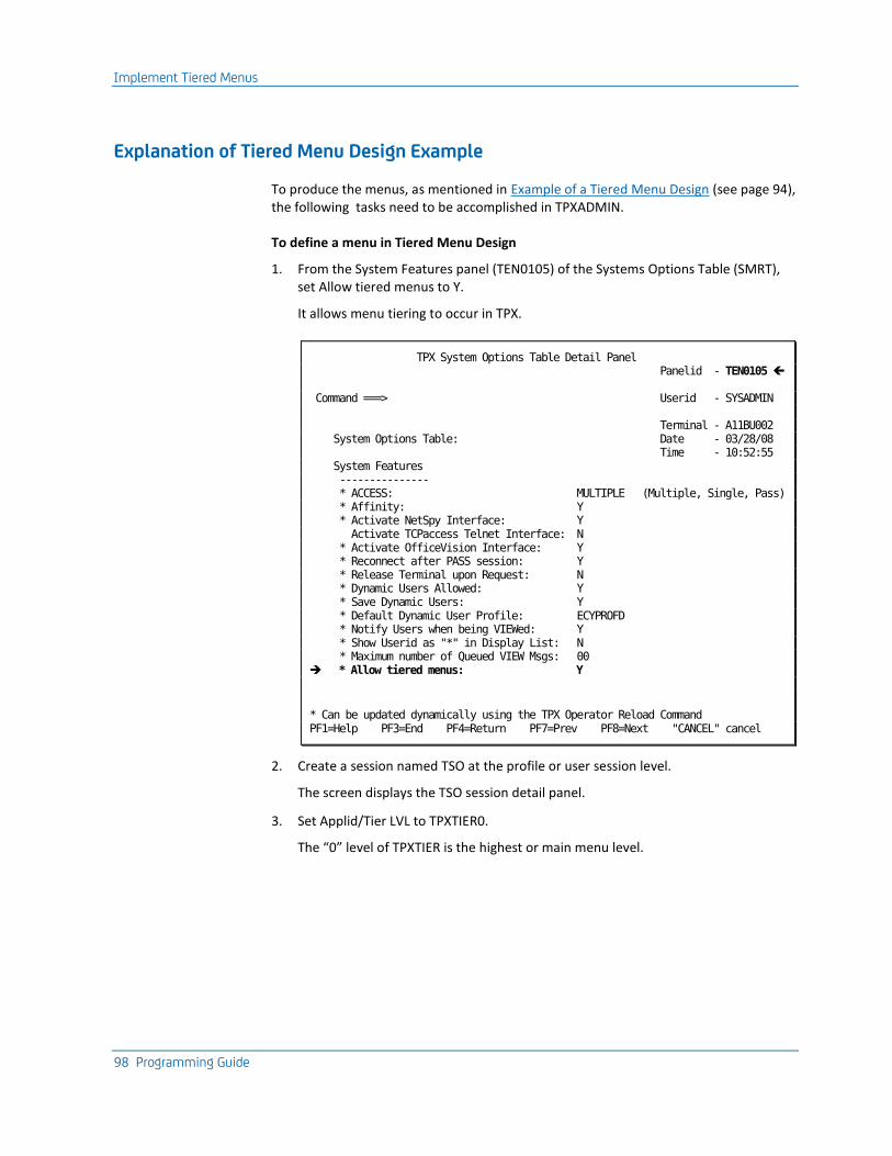
Implement Tiered Menus
98 Programming Guide
Explanation of Tiered Menu Design Example
To produce the menus, as mentioned in Example of a Tiered Menu Design (see page 94), the following tasks need to be accomplished in TPXADMIN.
To define a menu in Tiered Menu Design
1. From the System Features panel (TEN0105) of the Systems Options Table (SMRT), set Allow tiered menus to Y.
It allows menu tiering to occur in TPX.
TPX System Options Table Detail Panel Panelid - TEN0105 Command ===> Userid - SYSADMIN Terminal - A11BU002 System Options Table: Date - 03/28/08 Time - 10:52:55 System Features --------------- * ACCESS: MULTIPLE (Multiple, Single, Pass) * Affinity: Y * Activate NetSpy Interface: Y Activate TCPaccess Telnet Interface: N * Activate OfficeVision Interface: Y * Reconnect after PASS session: Y * Release Terminal upon Request: N * Dynamic Users Allowed: Y * Save Dynamic Users: Y * Default Dynamic User Profile: ECYPROFD * Notify Users when being VIEWed: Y * Show Userid as "*" in Display List: N * Maximum number of Queued VIEW Msgs: 00 * Allow tiered menus: Y
* Can be updated dynamically using the TPX Operator Reload Command PF1=Help PF3=End PF4=Return PF7=Prev PF8=Next "CANCEL" cancel
2. Create a session named TSO at the profile or user session level.
The screen displays the TSO session detail panel.
3. Set Applid/Tier LVL to TPXTIER0.
The “0” level of TPXTIER is the highest or main menu level.
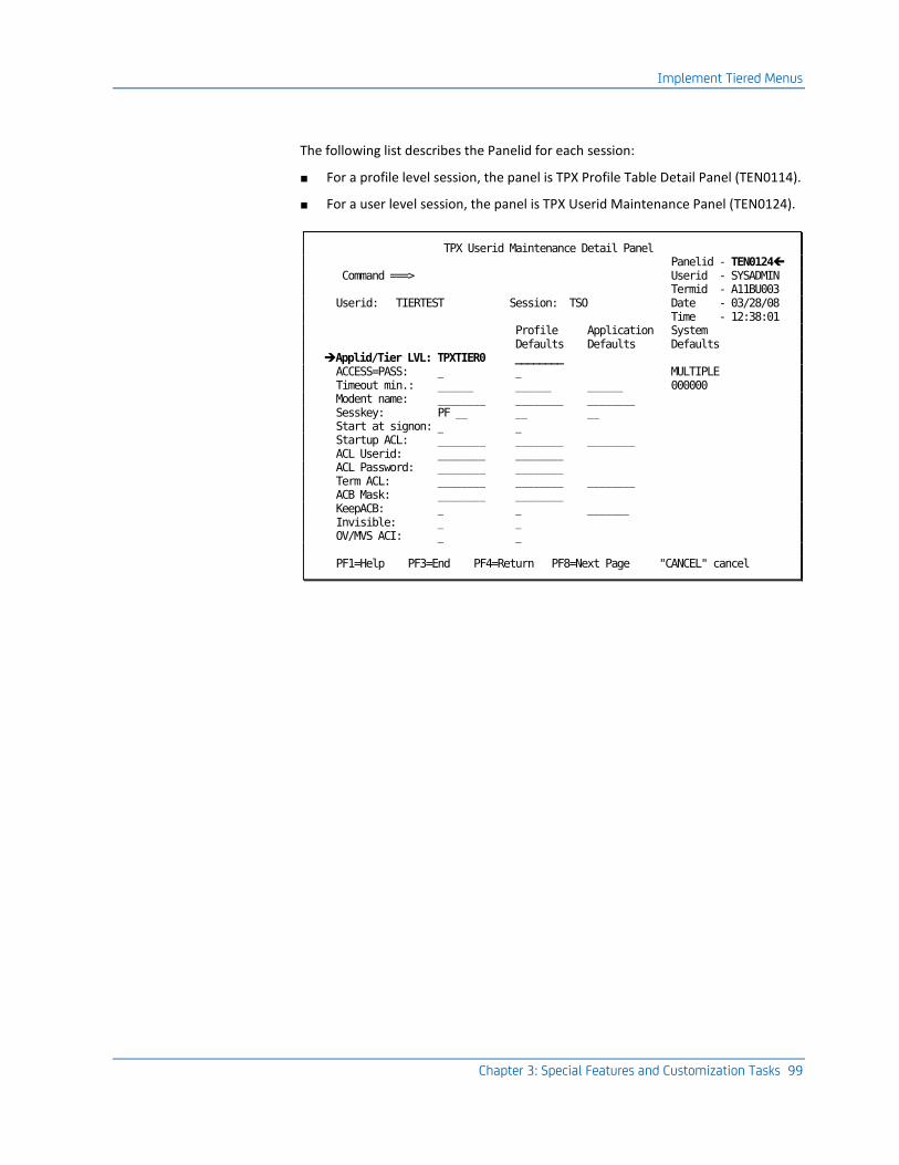
Implement Tiered Menus
Chapter 3: Special Features and Customization Tasks 99
The following list describes the Panelid for each session:
■ For a profile level session, the panel is TPX Profile Table Detail Panel (TEN0114).
■ For a user level session, the panel is TPX Userid Maintenance Panel (TEN0124).
TPX Userid Maintenance Detail Panel Panelid - TEN0124 Command ===> Userid - SYSADMIN Termid - A11BU003 Userid: TIERTEST Session: TSO Date - 03/28/08 Time - 12:38:01 Profile Application System Defaults Defaults Defaults Applid/Tier LVL: TPXTIER0 ________ ACCESS=PASS: _ _ MULTIPLE Timeout min.: ______ ______ ______ 000000 Modent name: ________ ________ ________ Sesskey: PF __ __ __ Start at signon: _ _ Startup ACL: ________ ________ ________ ACL Userid: ________ ________ ACL Password: ________ ________ Term ACL: ________ ________ ________ ACB Mask: ________ ________ KeepACB: _ _ _______ Invisible: _ _ OV/MVS ACI: _ _ PF1=Help PF3=End PF4=Return PF8=Next Page "CANCEL" cancel
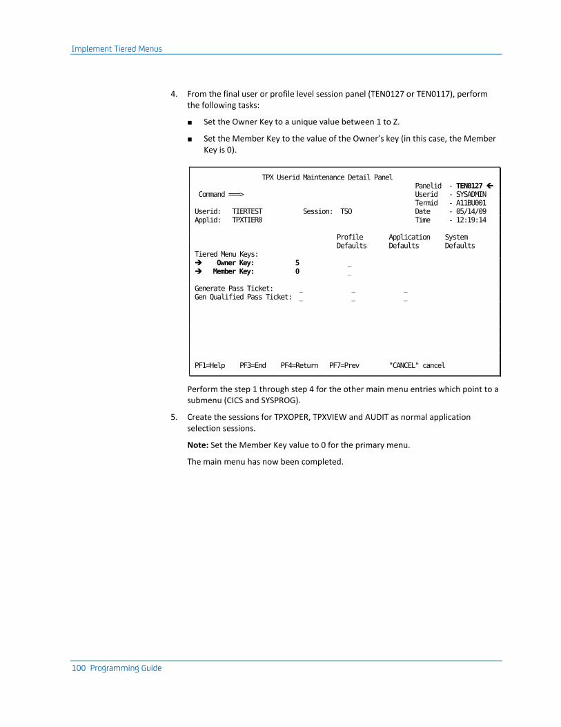
Implement Tiered Menus
100 Programming Guide
4. From the final user or profile level session panel (TEN0127 or TEN0117), perform the following tasks:
■ Set the Owner Key to a unique value between 1 to Z.
■ Set the Member Key to the value of the Owner’s key (in this case, the Member Key is 0).
TPX Userid Maintenance Detail Panel Panelid - TEN0127 Command ===> Userid - SYSADMIN Termid - A11BU001 Userid: TIERTEST Session: TSO Date - 05/14/09 Applid: TPXTIER0 Time - 12:19:14 Profile Application System Defaults Defaults Defaults Tiered Menu Keys: Owner Key: 5 _ Member Key: 0 _ Generate Pass Ticket: _ _ _ Gen Qualified Pass Ticket: _ _ _ PF1=Help PF3=End PF4=Return PF7=Prev "CANCEL" cancel
Perform the step 1 through step 4 for the other main menu entries which point to a submenu (CICS and SYSPROG).
5. Create the sessions for TPXOPER, TPXVIEW and AUDIT as normal application selection sessions.
Note: Set the Member Key value to 0 for the primary menu.
The main menu has now been completed.
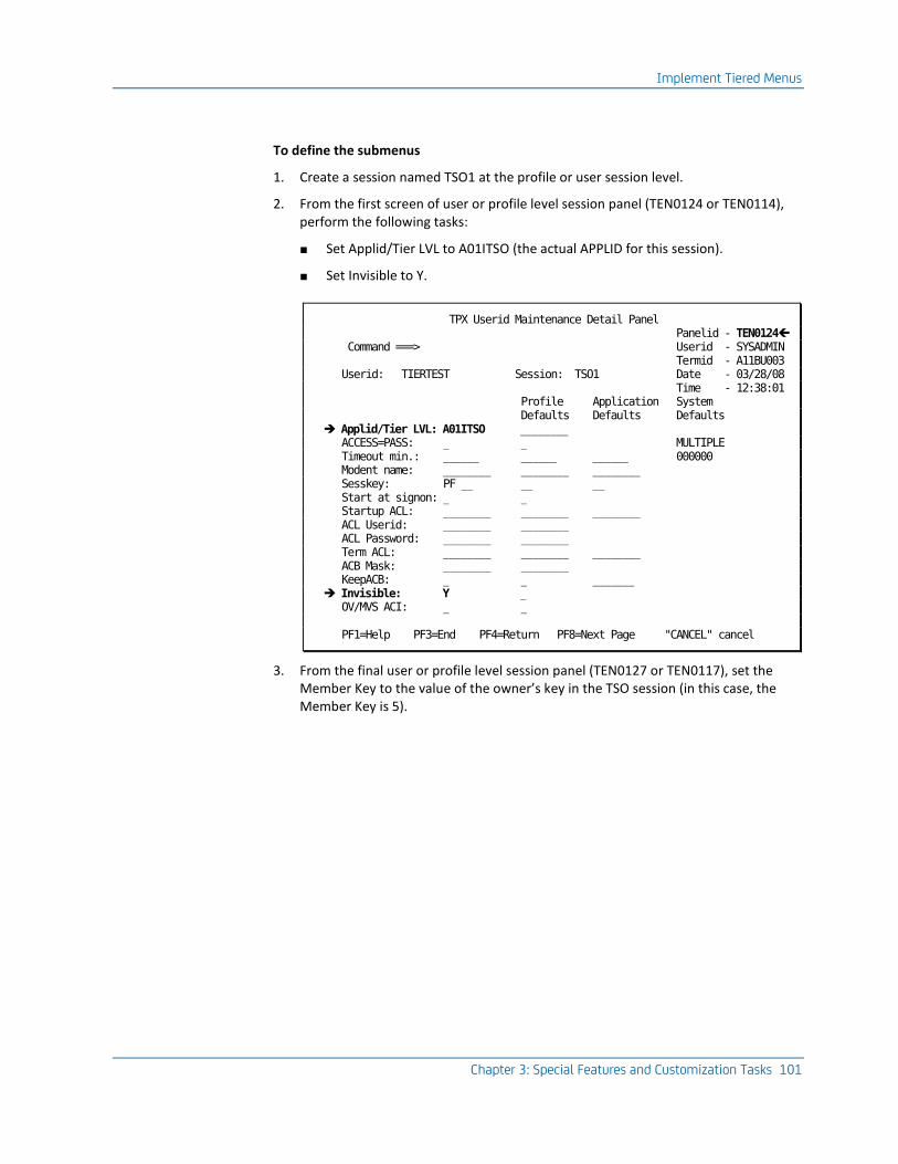
Implement Tiered Menus
Chapter 3: Special Features and Customization Tasks 101
To define the submenus
1. Create a session named TSO1 at the profile or user session level.
2. From the first screen of user or profile level session panel (TEN0124 or TEN0114), perform the following tasks:
■ Set Applid/Tier LVL to A01ITSO (the actual APPLID for this session).
■ Set Invisible to Y.
TPX Userid Maintenance Detail Panel Panelid - TEN0124 Command ===> Userid - SYSADMIN Termid - A11BU003 Userid: TIERTEST Session: TSO1 Date - 03/28/08 Time - 12:38:01 Profile Application System Defaults Defaults Defaults Applid/Tier LVL: A01ITSO ________ ACCESS=PASS: _ _ MULTIPLE Timeout min.: ______ ______ ______ 000000 Modent name: ________ ________ ________ Sesskey: PF __ __ __ Start at signon: _ _ Startup ACL: ________ ________ ________ ACL Userid: ________ ________ ACL Password: ________ ________ Term ACL: ________ ________ ________ ACB Mask: ________ ________ KeepACB: _ _ _______ Invisible: Y _ OV/MVS ACI: _ _ PF1=Help PF3=End PF4=Return PF8=Next Page "CANCEL" cancel
3. From the final user or profile level session panel (TEN0127 or TEN0117), set the Member Key to the value of the owner’s key in the TSO session (in this case, the Member Key is 5).

Implement Tiered Menus
102 Programming Guide
TPX Userid Maintenance Detail Panel Panelid - TEN0127 Command ===> Userid - SYSADMIN Termid - A11BU001 Userid: TIERTEST Session: TSO Date - 05/14/09 Applid: TPXTIER0 Time - 12:19:14 Profile Application System Defaults Defaults Defaults Tiered Menu Keys: Owner Key: _ _ Member Key: 5 _ Generate Pass Ticket: _ _ _ Gen Qualified Pass Ticket: _ _ _ PF1=Help PF3=End PF4=Return PF7=Prev "CANCEL" cancel
Create sessions TSO2 and TSO3 each for APPLIDs, A02ITSO, and A03ITSO. Perform steps 1 through step 3.
Thus the TSO submenu is defined.
Now create the same types of sessions for CICS 1 through 3. Now 2 submenus are completed – TSO and CICS.
The final submenu SYSPROG contains two entries, NETVIEW and SYSVIEW.
To define NETVIEW session in SYSPROG
1. Create a session named NETVIEW.
2. In that session detail panel set Applid/Tier LVL to TPXTIER1.
The 1 level of TPXTIER indicates the next level of submenus.
3. Set Invisible to Y.
4. From the final screen of user or profile level session panel (TEN0127 or TEN0117), perform the following tasks:
■ Set the Owner Key to a unique value between 1 and Z.
■ Set the Member Key to the value of the owner’s key in the SYSPROG session.
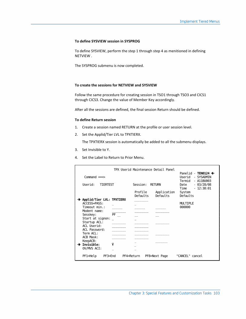
Implement Tiered Menus
Chapter 3: Special Features and Customization Tasks 103
To define SYSVIEW session in SYSPROG
To define SYSVIEW, perform the step 1 through step 4 as menitioned in defining NETVIEW .
The SYSPROG submenu is now completed.
To create the sessions for NETVIEW and SYSVIEW
Follow the same procedure for creating session in TSO1 through TSO3 and CICS1 through CICS3. Change the value of Member Key accordingly.
After all the sessions are defined, the final session Return should be defined.
To define Return session
1. Create a session named RETURN at the profile or user session level.
2. Set the Applid/Tier LVL to TPXTIERX.
The TPXTIERX session is automatically be added to all the submenu displays.
3. Set Invisible to Y.
4. Set the Label to Return to Prior Menu.
TPX Userid Maintenance Detail Panel Panelid - TEN0124 Command ===> Userid - SYSADMIN Termid - A11BU003 Userid: TIERTEST Session: RETURN Date - 03/28/08 Time - 12:38:01 Profile Application System Defaults Defaults Defaults Applid/Tier LVL: TPXTIERX ________ ACCESS=PASS: _ _ MULTIPLE Timeout min.: ______ ______ ______ 000000 Modent name: ________ ________ ________ Sesskey: PF __ __ __ Start at signon: _ _ Startup ACL: ________ ________ ________ ACL Userid: ________ ________ ACL Password: ________ ________ Term ACL: ________ ________ ________ ACB Mask: ________ ________ KeepACB: _ _ _______ Invisible: Y _ OV/MVS ACI: _ _ PF1=Help PF3=End PF4=Return PF8=Next Page "CANCEL" cancel

Implement Tiered Menus
104 Programming Guide
Thus, all the sessions mentioned in Example of a Tiered Menu Design (see page 94) are defined and the list of sessions appear as shown in the following screen:
TPX Userid Maintenance Table Entry List Panelid - TEN0122 Command ===> Userid - SYSADMIN Termid - A11BU003 Userid: TPXUSER1 Profile System Date - 03/28/08 Defaults Defaults Time - 12:33:29 Command key: _______ _______ PF12/24 Jump key: _____ _____ NONE Menu key: _____ _____ PF4 Print key: _____ _____ NONE Applid/ Profile Tier LVL Applid/ Sesskey Profile Menu Profile Session Override Tier LVL Override Sesskey Order Order AUDIT TPXDEMO ________ PF __ PF __ 006 ___ CICS TPXTIER0 ________ PF __ PF __ 002 ___ CICS1 A01ICICS ________ PF __ PF __ 001 ___ CICS2 A02ICICS ________ PF __ PF __ 002 ___ CICS3 A03ICICS ________ PF __ PF __ 003 ___ NETVIEW TPXTIER1 ________ PF __ PF __ 001 ___ NETVIEW1 A01INTVW ________ PF __ PF __ 001 ___ NETVIEW2 A02INTVW ________ PF __ PF __ 002 ___ NETVIEW3 A03INTVW ________ PF __ PF __ 003 ___ RETURN TPXTIERX ________ PF __ PF __ 255 ___ SYSPROG TPXTIER0 ________ PF __ PF __ 003 ___ SYSVIEW TPXTIER1 ________ PF __ PF __ 002 ___ SYSVIEW1 A01ISYVW ________ PF __ PF __ 001 ___ SYSVIEW2 A02ISYVW ________ PF __ PF __ 002 ___ SYSVIEW3 A03ISYVW ________ PF __ PF __ 003 ___ TPXOPER TPXOPER ________ PF __ PF __ 004 ___ TPXVIEW TPXVIEW ________ PF __ PF __ 005 ___ TSO TPXTIER0 ________ PF __ PF __ 001 ___ TSO1 A01ITSO ________ PF __ PF __ 001 ___ TSO2 A02ITSO ________ PF __ PF __ 002 ___ TSO3 A03ITSO ________ PF __ PF __ 003 ___ ******************************** BOTTOM OF DATA ******************************* PF1=Help PF3=End PF4=Return PF7=Up PF8=Down "CANCEL" cancel
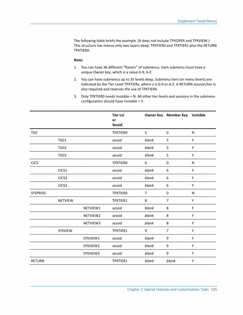
Implement Tiered Menus
Chapter 3: Special Features and Customization Tasks 105
The following table briefs the example. (It does not include TPXOPER and TPXVIEW.) This structure has menus only two layers deep: TPXTIER0 and TPXTIER1 plus the RETURN TPXTIERX.
Note:
1. You can have 36 different “flavors” of submenus. Each submenu must have a unique Owner key, which is a value 0-9, A-Z.
2. You can have submenus up to 35 levels deep. Submenu tiers (or menu levels) are indicated by the Tier Level TPXTIERx, where x is 0-9 or A-Z. A RETURN session/tier is also required and reserves the use of TPXTIERX.
3. Only TPXTIER0 needs Invisible = N. All other tier levels and sessions in the submenu configuration should have Invisible = Y.
Tier Lvl or Sessid
Owner Key Member Key Invisible
TSO TPXTIER0 5 0 N
TSO1 sessid blank 5 Y
TSO2 sessid blank 5 Y
TSO3 sessid blank 5 Y
CICS TPXTIER0 6 0 N
CICS1 sessid blank 6 Y
CICS2 sessid blank 6 Y
CICS3 sessid blank 6 Y
SYSPROG TPXTIER0 7 0 N
NETVIEW TPXTIER1 8 7 Y
NETVIEW1 sessid blank 8 Y
NETVIEW2 sessid blank 8 Y
NETVIEW3 sessid blank 8 Y
SYSVIEW TPXTIER1 9 7 Y
SYSVIEW1 sessid blank 9 Y
SYSVIEW2 sessid blank 9 Y
SYSVIEW3 sessid blank 9 Y
RETURN TPXTIER1 blank blank Y

Chapter 4: Customizing for Certain Applications 107
Chapter 4: Customizing for Certain Applications
As a VTAM application, CA TPX needs information about the specific characteristics of the application to which it is connected. You define these characteristics on the Application Characteristics Table (ACT) in administration. Some applications, however, require additional customization to work properly with this product. This chapter provides information about the special requirements of vendor-supplied applications such as TSO, CICS, and IMS.
This section contains the following topics:
Define Shared Applications (see page 107) Defining Group Applications (see page 108) Special Considerations for Certain Applications (see page 108) Customize CICS Transaction Server (see page 109) Customize HCF (see page 116) Customize CAIDMS (see page 118) Customize IMS (see page 119) Customize the IBM Information Network (see page 124) Customize Netview/NCCF (see page 125) Customize NetSpy (see page 125) Customize TCAM (see page 126) Customize TSO (see page 126) Customize VSPC (see page 128)
Define Shared Applications
The following shared applications have special requirements when you define them to CA TPX:
■ CA-Remote
■ RMDS (prior to Put 8702)
■ CA-Roscoe
■ CA STX
To define each shared application
1. Specify a value of SHR in the Type field of the ACT.
2. Specify PARSESS=YES in the application definition in SYS1.VTAMLST.
This allows parallel sessions for the application. If you do not specify PARSESS=YES, only one user will be able to access the application at a time.
Defining Group Applications
108 Programming Guide
Example
The application definition for CA-Remote would look like this:
SCON APPL AUTH=ACQ,PARSESS=YES,EAS=n...
Notes:
1. Do not use the CA-Roscoe PASS facility, which allows users to pass directly from this product to another application.
2. For RMDS after Put 8702, define RMDS as a group application, and do not specify PARSESS=YES in the application definition.
Defining Group Applications
The following group applications have special requirements when you define them to CA TPX:
■ CA IDMS/DC
■ IIPS
■ Omegamon
■ Phoenix
■ RMDS (after Put 8702)
■ CA-7
■ VM/VCNA
■ VM/VSCS (VM/SNA native)
To define a group application to CA TPX, specify a value of GRP in the Type field of the ACT.
Special Considerations for Certain Applications
Some applications require some special customization when you use them with this product. The following list shows the applications with special requirements and a reference to where the application is discussed:
■ CA IDMS
■ CICS Transaction Server
■ HCF
■ IMS
■ IBM Information Network
Customize CICS Transaction Server
Chapter 4: Customizing for Certain Applications 109
■ NetView/NCCF
■ NetSpy
■ TCAM
■ TSO
■ VSPC
Customize CICS Transaction Server
Unlike most other applications, CICS does not use the VTAM-supplied description of a terminal when a user initiates a session. Instead, CICS uses a special module called the Terminal Control Table (TCT) to determine terminal characteristics. You provide the description for each terminal that a user may use to initiate a CICS session. This restricts the freedom of the remote operator to move terminals around on the 3x74 controller.
When the terminal logs on to CICS, it must have the characteristics that CICS expects it to have based on the TCT entry for the terminal. When this product starts a session with an application, it normally selects the next available virtual terminal. Therefore, if a user is logging on from a model 2 terminal, the product may select a virtual terminal that is defined in the CICS TCT as a model 3 terminal. The result would be session failure or incorrect screen output.
Each TYPETERM definition must be installed before or at the same time as the TERMINAL definitions that reference it. When using CEDA to install groups, if the TYPETERMs are in a separate group from the TERMINALs, the TYPETERMs group must be installed before the TERMINALs. Changing a TYPETERM definition and then reinstalling it has no effect on an already installed terminal entry, even though the TERMINAL definition used to create it refers to the TYPETERM. To change the terminal entry, both the TYPETERM and the TERMINAL need to be reinstalled.
Create an Application Definition
To create an application definition for CICS
1. In the Type field of the ACT, specify UNQ (if you are using EXEC CICS PASS) or GRP (if you are not using EXEC CICS PASS).
Note: If you are not using the RDO feature of CICS to dynamically define TCT entries, follow only steps 2 through 5 of the procedure Creating an Application Definition in this chapter.
2. If you are using EXEC CICS PASS, specify Y in the Keep virtual terminal field of the ACT.
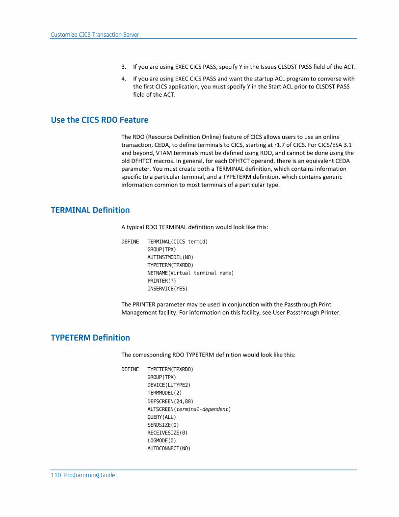
Customize CICS Transaction Server
110 Programming Guide
3. If you are using EXEC CICS PASS, specify Y in the Issues CLSDST PASS field of the ACT.
4. If you are using EXEC CICS PASS and want the startup ACL program to converse with the first CICS application, you must specify Y in the Start ACL prior to CLSDST PASS field of the ACT.
Use the CICS RDO Feature
The RDO (Resource Definition Online) feature of CICS allows users to use an online transaction, CEDA, to define terminals to CICS, starting at r1.7 of CICS. For CICS/ESA 3.1 and beyond, VTAM terminals must be defined using RDO, and cannot be done using the old DFHTCT macros. In general, for each DFHTCT operand, there is an equivalent CEDA parameter. You must create both a TERMINAL definition, which contains information specific to a particular terminal, and a TYPETERM definition, which contains generic information common to most terminals of a particular type.
TERMINAL Definition
A typical RDO TERMINAL definition would look like this:
DEFINE TERMINAL(CICS termid)
GROUP(TPX)
AUTINSTMODEL(NO)
TYPETERM(TPXRDO)
NETNAME(Virtual terminal name)
PRINTER(?)
INSERVICE(YES)
The PRINTER parameter may be used in conjunction with the Passthrough Print Management facility. For information on this facility, see User Passthrough Printer.
TYPETERM Definition
The corresponding RDO TYPETERM definition would look like this:
DEFINE TYPETERM(TPXRDO)
GROUP(TPX)
DEVICE(LUTYPE2)
TERMMODEL(2)
DEFSCREEN(24,80)
ALTSCREEN(terminal-dependent)
QUERY(ALL)
SENDSIZE(0)
RECEIVESIZE(0)
LOGMODE(0)
AUTOCONNECT(NO)
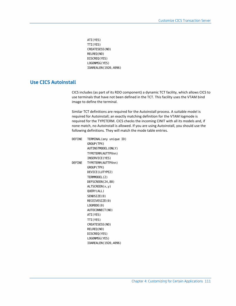
Customize CICS Transaction Server
Chapter 4: Customizing for Certain Applications 111
ATI(YES)
TTI(YES)
CREATESESS(NO)
RELREQ(NO)
DISCREQ(YES)
LOGONMSG(YES)
IOAREALEN(1920,4096)
Use CICS Autoinstall
CICS includes (as part of its RDO component) a dynamic TCT facility, which allows CICS to use terminals that have not been defined in the TCT. This facility uses the VTAM bind image to define the terminal.
Similar TCT definitions are required for the Autoinstall process. A suitable model is required for Autoinstall; an exactly matching definition for the VTAM logmode is required for the TYPETERM. CICS checks the incoming CINIT with all its models and, if none match, no Autoinstall is allowed. If you are using Autoinstall, you should use the following definitions. They will match the mode table entries.
DEFINE TERMINAL(any unique ID)
GROUP(TPX)
AUTINSTMODEL(ONLY)
TYPETERM(AUTTPXnn)
INSERVICE(YES)
DEFINE TYPETERM(AUTTPXnn)
GROUP(TPX)
DEVICE(LUTYPE2)
TERMMODEL(2)
DEFSCREEN(24,80)
ALTSCREEN(x,y)
QUERY(ALL)
SENDSIZE(0)
RECEIVESIZE(0)
LOGMODE(0)
AUTOCONNECT(NO)
ATI(YES)
TTI(YES)
CREATESESS(NO)
RELREQ(NO)
DISCREQ(YES)
LOGONMSG(YES)
IOAREALEN(1920,4096)
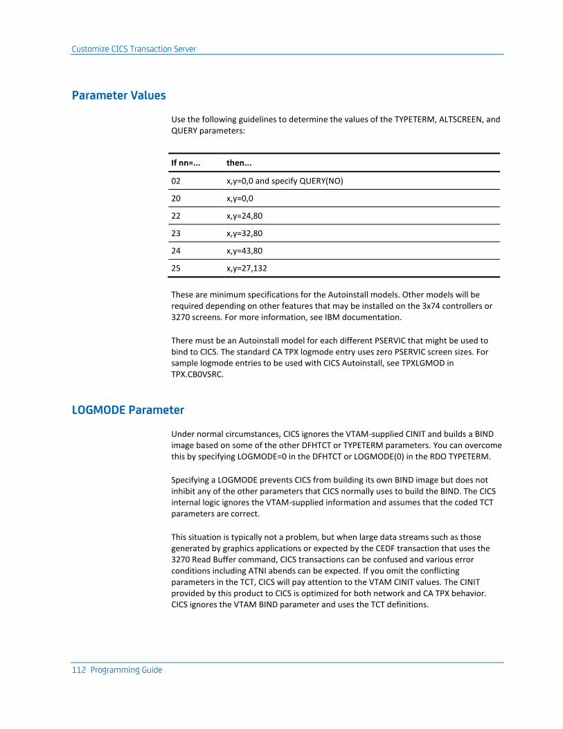
Customize CICS Transaction Server
112 Programming Guide
Parameter Values
Use the following guidelines to determine the values of the TYPETERM, ALTSCREEN, and QUERY parameters:
If nn=... then...
02 x,y=0,0 and specify QUERY(NO)
20 x,y=0,0
22 x,y=24,80
23 x,y=32,80
24 x,y=43,80
25 x,y=27,132
These are minimum specifications for the Autoinstall models. Other models will be required depending on other features that may be installed on the 3x74 controllers or 3270 screens. For more information, see IBM documentation.
There must be an Autoinstall model for each different PSERVIC that might be used to bind to CICS. The standard CA TPX logmode entry uses zero PSERVIC screen sizes. For sample logmode entries to be used with CICS Autoinstall, see TPXLGMOD in TPX.CB0VSRC.
LOGMODE Parameter
Under normal circumstances, CICS ignores the VTAM-supplied CINIT and builds a BIND image based on some of the other DFHTCT or TYPETERM parameters. You can overcome this by specifying LOGMODE=0 in the DFHTCT or LOGMODE(0) in the RDO TYPETERM.
Specifying a LOGMODE prevents CICS from building its own BIND image but does not inhibit any of the other parameters that CICS normally uses to build the BIND. The CICS internal logic ignores the VTAM-supplied information and assumes that the coded TCT parameters are correct.
This situation is typically not a problem, but when large data streams such as those generated by graphics applications or expected by the CEDF transaction that uses the 3270 Read Buffer command, CICS transactions can be confused and various error conditions including ATNI abends can be expected. If you omit the conflicting parameters in the TCT, CICS will pay attention to the VTAM CINIT values. The CINIT provided by this product to CICS is optimized for both network and CA TPX behavior. CICS ignores the VTAM BIND parameter and uses the TCT definitions.
Customize CICS Transaction Server
Chapter 4: Customizing for Certain Applications 113
Because this product is not notified of the CICS TCT parameter, do the following to avoid ATNI or AEDF abends:
■ If you specify LOGMODE=0, specify BUFFER=0,RUSIZE=0.
■ If you specify LOGMODE=name, do not specify BUFFER or RUSIZE.
Use Passthrough Printing
If you are taking advantage of the Passthrough Printing facility, you can use the RDO PRINTER parameter to associate a virtual printer with a virtual terminal. You can then use the User Passthrough Printer Table Mask to associate the virtual printer to the user. CA TPX will use the printer name supplied in the user definition or Terminal Options Table to determine which actual printer to use to complete the print operation.
If you use a compiled printer table in your CICS transactions to allocate printers, you may allocate virtual printers to virtual terminals and use the Printer Selection exit to use the same tables directly from CA TPX. For more information, see Printer Selection Exit (see page 163).
More information:
Printer Selection Exit (see page 163)
CICS RDO TERMINAL Parameters
The following CICS RDO TERMINAL parameters affect this product's execution:
TERMINAL(CICS termid)
Specifies the 4-byte CICS terminal ID. In the case of an Autoinstall model, this parameter is not used, so you can specify any unique name.
GROUP(TPX)
Groups definitions together. You can specify any name, but if possible, specify one that indicates these are CA TPX definitions.
AUTINSTMODEL (NO|ONLY)
Tells whether the TERMINAL definition is for an Autoinstall model. Possible values are:
NO
Indicates that the terminal is not used as an Autoinstall model.
ONLY
Indicates that the terminal is used only as an Autoinstall model.
Customize CICS Transaction Server
114 Programming Guide
TYPETERM(typeterm-name)
Points to the corresponding TYPETERM definition for this terminal. Note that for Autoinstall, CICS searches through TYPETERM names alphanumerically and sometimes selects an existing TYPETERM for a virtual terminal before TYPETERM. Therefore, it may be necessary to name the TYPETERM so that it is alphanumerically in front of any of your other TYPETERM definitions.
NETNAME(VTAM luname)
VTAM luname of the virtual terminal. In the case of an Autoinstall model, this parameter is not used, so you can specify any unique name.
PRINTER(printerid)
CICS terminal ID of associated printer.
NSERVICE(YES)
Specifies that the terminal must be in service to CICS, or logons will not be successful.
CICS RDO TYPETERM Parameters
The following TYPETERM parameters affect this product's execution:
TYPETERM(typeterm-name)
Name of this TYPETERM definition. Note that for Autoinstall, CICS searches through TYPETERM names alphanumerically and sometimes selects an existing TYPETERM for a virtual terminal before TYPETERM. Therefore, it may be necessary to name the TYPETERM so that it is alphanumerically in front of any of your other TYPETERM definitions.
Note: For more information, see the CICS Resource Definition Guide.
GROUP(TPX)
Groups definitions together. You can specify any name, but if possible, specify one that indicates these are CA TPX definitions.
DEVICE(LUTYPE2)
This parameter must be specified as LUTYPE2 for all virtual terminals.
TERMMODEL(2)
This parameter must be specified as 2 for all virtual terminals.
DEFSCREEN(24,80)
The primary screen size for the virtual terminal. This should always be 24,80.
ALTSCREEN(x,y)
The alternate screen size of the virtual terminal. This will vary depending on the logmode used to log on to CICS. For example, for a model 2, this would be 24,80.
Customize CICS Transaction Server
Chapter 4: Customizing for Certain Applications 115
QUERY(ALL)
Indicates whether the terminal supports the Read Partition Query data stream. This allows CICS to query the terminal to see what extended options the terminal supports, such as EXTENDEDDS, COLOR, and HILIGHT. For this product, all virtual terminals that use a logmode ending in E can be queried. Specify this parameter as N if the terminal cannot be queried. Specify this parameter as Y if the terminal can be queried.
SENDSIZE(0)
Indicates the maximum size of data that CICS should send to the virtual terminal. Always specify this value as 0, which causes CICS to use the appropriate RUSIZE from the logmode entry used to log on to CICS. If you do specify a value other than 0, it must match the appropriate RUSIZE in the logmode entry.
RECEIVESIZE(0)
Indicates the maximum size of data that CICS will receive from the virtual terminal. Always specify this value as 0, which causes CICS to use the appropriate RUSIZE from the logmode entry used to log on to CICS. If you do specify a value other than 0, it must match the appropriate RUSIZE in the logmode entry.
LOGMODE(0)
Determines the BIND parameters used by CICS when starting a session with the virtual terminal. Always specify this value as 0, which causes CICS to use the values from the logmode used by the virtual terminal. If you do specify a logmode name, it should match the name used by the virtual terminal. If you specify this parameter as all blanks, CICS will build a BIND image on its own.
AUTOCONNECT(NO)
Tells CICS whether the terminal should be logged on to CICS automatically when CICS starts up. This parameter must be specified as NO for virtual terminals.
ATI(YES)
Tells CICS whether transactions can be automatically initiated at this virtual terminal. Specify YES for this parameter, especially if LOGONMSG(YES) is also specified for this virtual terminal. LOGONMSG(YES) causes the CICS good morning transaction (CSGM) to be initiated automatically at logon.
Customize HCF
116 Programming Guide
TTI(YES)
Tells CICS whether transactions can be initiated by typing in the transaction ID from the terminal. Always specify YES, or users will not be able to start any CICS transactions from this virtual terminal.
CREATESESS(NO)
Tells CICS whether it should try to start a session with this virtual terminal if none exists, but a transaction has been started using ATI. You must specify NO for virtual terminals.
RELREQ(NO)
Tells CICS whether it should release this virtual terminal upon receipt of a RELREQ request from another VTAM application. Specify NO for virtual terminals.
DISCREQ(YES)
Tells CICS whether it should allow the virtual terminal to disconnect from CICS. Specify YES, so that a CESF (or CSSF) LOGOFF will allow the session with the virtual terminal to end.
LOGONMSG(YES)
Tells CICS whether it should send the good morning message to the virtual terminal when it first logs on to CICS. This causes the CICS good morning transaction (CSGM) to be initiated by ATI, which also requires that you specify ATI(YES). Always specify YES, unless you always want the user to enter data first to CICS.
IOAREALEN(1920,4096)
Tells CICS the size of the area used to hold data received from the terminal. The first value is the minimum size of the area CICS will acquire on input from a terminal. If the data received from the terminal is longer than the first value, CICS will use the second value to get storage for the data. If the data is longer than the second value, the transaction will abend. These two values are dependent on your applications and terminals.
Customize HCF
HCF is a special VTAM application that allows terminal users in an SNA network to access applications residing on an 8100 processor. An 8100 is not a true SNA host, because it does not allow an 8100 application to be a primary logical unit (PLU). HCF executes on the mainframe and acts as the PLU for both the 8100 processor and the accessing terminal.
Customize HCF
Chapter 4: Customizing for Certain Applications 117
There are two different 8100 operating systems, DPCX and DPPX. Both operating systems have a slightly different relationship to HCF and require HCF to have a slightly different relationship to its terminals. Because this product acts on behalf of 8100 terminals, you need to perform some special customization tasks when you set up the product to use HCF.
Note: HCF may also be used to contact an AS/400 machine running DHCF support. DHCF requires the logmode to have the query bit set to zero in the PSERVIC. The standard logmode T3278M2 is suitable for this purpose and should be specified in application session options in the Modent name field of the User Maintenance Detail panel or the Profile Table Detail panel.
Create an Application Definition
To create an application definition for HCF
1. Specify GRP in the Type field of the ACT.
2. If your site uses both DPPX and DPCX, you can specify the HCF LOGMODE entry at the user or profile level. Specify CS3270 (for DPCX) or PS3270 (for DPPX) in the Modent name field in application session options for the user or profile (see the Administration Guide).
3. If your site uses either DPPX or DPCX, you can specify the HCF LOGMODE entry at the application level. Specify CS3270 (for DPCX) or PS3270 (for DPPX) in the Mode entry override field of the ACT.
4. If your site uses DPPX, specify Y in the Model sensitive field of the ACT.
Logon Mode Tables
Because the logon mode table entries that supply session characteristics used with HCF are unique, you cannot use standard logon mode tables. Suitable mode table entries have been included in the distributed logon mode tables and can be found in source form in TPX.CB0VSRC.
DPCX
DPCX does not support model 3, 4, and 5 terminal screens. The following LOGMODE entry has been provided in all the logon mode tables:
HCS3270 MODEENT LOGMODE=CS3270,FMPROF=X'03',TSPROF=X'03'
PRIPROT=X'B1',SECPROT=X'B0',COMPROT=X'3080',
RUSIZES=X'A8A8',
PSERVIC=X'020000000000000000000200'
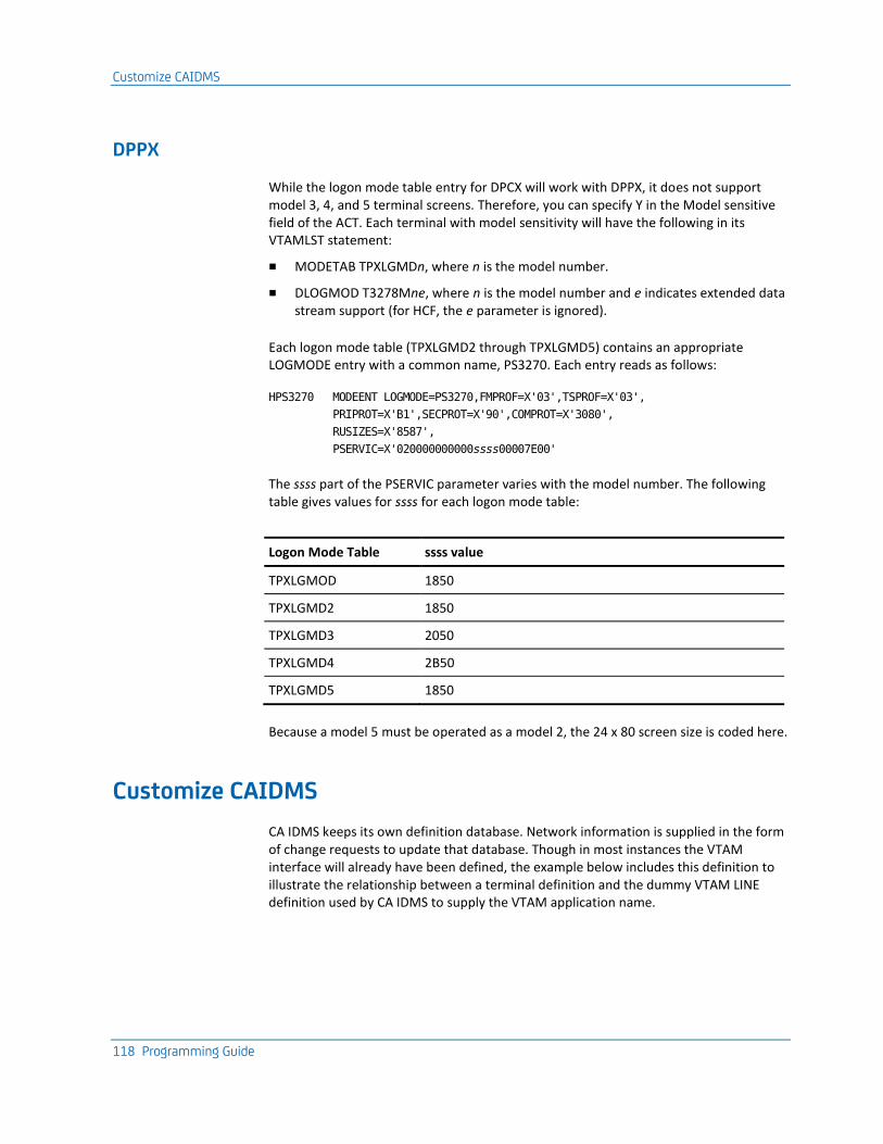
Customize CAIDMS
118 Programming Guide
DPPX
While the logon mode table entry for DPCX will work with DPPX, it does not support model 3, 4, and 5 terminal screens. Therefore, you can specify Y in the Model sensitive field of the ACT. Each terminal with model sensitivity will have the following in its VTAMLST statement:
■ MODETAB TPXLGMDn, where n is the model number.
■ DLOGMOD T3278Mne, where n is the model number and e indicates extended data stream support (for HCF, the e parameter is ignored).
Each logon mode table (TPXLGMD2 through TPXLGMD5) contains an appropriate LOGMODE entry with a common name, PS3270. Each entry reads as follows:
HPS3270 MODEENT LOGMODE=PS3270,FMPROF=X'03',TSPROF=X'03',
PRIPROT=X'B1',SECPROT=X'90',COMPROT=X'3080',
RUSIZES=X'8587',
PSERVIC=X'020000000000ssss00007E00'
The ssss part of the PSERVIC parameter varies with the model number. The following table gives values for ssss for each logon mode table:
Logon Mode Table ssss value
TPXLGMOD 1850
TPXLGMD2 1850
TPXLGMD3 2050
TPXLGMD4 2B50
TPXLGMD5 1850
Because a model 5 must be operated as a model 2, the 24 x 80 screen size is coded here.
Customize CAIDMS
CA IDMS keeps its own definition database. Network information is supplied in the form of change requests to update that database. Though in most instances the VTAM interface will already have been defined, the example below includes this definition to illustrate the relationship between a terminal definition and the dummy VTAM LINE definition used by CA IDMS to supply the VTAM application name.
Customize IMS
Chapter 4: Customizing for Certain Applications 119
Create an Application Definition
When creating an application definition, specify GRP in the Type field of the ACT.
Define Virtual Terminals
To define each virtual terminal to CA IDMS
1. Use the following ADD LINE statement to define VTAM to CA IDMS:
ADD LINE name-1 TYPE IS VTAMLU ENABLED
APPLICATION ID IS name-2
The variable name-1 is used to associate ADD PTERM statements with this ADD LINE statement. The variable name-2 is the VTAM application-ID specified in the Applid field of the ACT.
2. Use the following ADD PTERM statement to add the CA TPX virtual terminal and associate it with VTAM:
ADD PTERM vterm-name ENABLED NOREADBUFFER NOAQUIRE
IN LINE name-1 TYPE IS LU
The variable vterm-name is the VTAM LU name of the virtual terminal.
3. For each ADD PTERM statement, an ADD LTERM statement such as the following is required:
ADD LTERM any-name INTERACTIVE PTERM IS vterm-name
NOBREAK UPLOW
Notes:
1. In the ADD LTERM statement above, you could specify BREAK or UPPER instead of NOBREAK and UPLOW, but it is possible that using BREAK, with SDLC terminals may lead to additional protocol elements being sent to the terminal.
2. The ADD PTERM and ADD LTERM statements can have other CA IDMS related parameters. For more information, see Advantage CA-IDMS System Generation.
Customize IMS
If you want to use IMS with this product, you must follow the procedure in this section for creating the application definition for IMS. This section also discusses some considerations for tailoring IMS to work with this product.
Customize IMS
120 Programming Guide
Creating an Application Definition
To create an application definition for IMS
1. Specify GRP in the Type field of the ACT.
2. If your IMS applications limit access to certain transactions based on the PTERM name, you may want to use virtual terminal masking rules.
For more information, see the Administration Guide.
3. If your IMS system queues output to an LTERM after a user signs off, you may want to specify Y in the Keep virtual terminal field of the ACT.
4. If you have configured your IMS in an XRF environment, you can specify the USERVAR name in the Applid field and Y in the XRF application field of the ACT.
Prior to starting a session, CA TPX will issue an INQUIRE USERVAR to obtain the correct application ID with which to connect.
Sample of IMSGEN Statements
You use the IMSGEN statements in the following example to define terminals to an IMS system:
label TYPE UNITYPE=SLUTYPE2,...
label TERMINAL TYPE=3270An,
OUTBUFF=2048,
NAME=vtam-terminal-name,
FEAT=IGNORE,
OPTIONS=(TRANRESP,
NOCOPY,
NOPNDST)
SIZE=(row,column),
label NAME lterm
label TERMINAL...
.
.
.
label NAME lterm
.
.
.
Customize IMS
Chapter 4: Customizing for Certain Applications 121
Description of IMSGEN Statements
The following list describes statements in the IMSGEN entry:
TYPE
Defines logical statement that gathers together terminals with similar characteristics. This product looks to IMS as an SLU TYPE 2.
IMS does not verify the VTAM bind image against its own definition tables and will not reject an inconsistent bind. If the virtual terminals are defined as TYPE=3277, IMS assumes an LU type of 0 even when an LU type 2 bind is received. IMS will bind with an LU type of 2, but will assume an LU type of 0 internally, which causes many problems. Therefore, the IMS CA TPX virtual terminals must be defined as TYPE=SLUTYPE2.
TERMINAL
Defines each terminal. The n is the IMS model number (01 through 15). Only models 1-8 are supported.
You must specify the correct value in the SIZE parameter for the TYPE that you specify here, but any model of terminal will work if TYPE = 3270A2 and SIZE = 24,80. For more information, see the Size parameter below.
OUTBUFF
IMS requires non-SNA terminals to have an OUTBUFF value greater than the largest message expected to be sent to the terminal. This is because the LU0 bind image has no MAXRU facility and cannot use chaining. This is not true for LU2, which segments the message according to the BIND MAXRU size. For CA TPX, the BIND MAXRU size is 2 KB, so an OUTBUFF value of 2048 is recommended. The use of LU2 saves valuable IMS virtual storage.
FEAT
Defaults to (PFK,CARD,PEN), but it is not important to specify them.
OPTIONS
Use the value you would normally use when defining an LU type 2 terminal (TRANRESP, FORCRESP, or NORESP).
NOCOPY
For BSC 3270 or local non-SNA devices, it is not possible to specify a COPY facility in the IMSGEN. However, for LU2 devices, coding COPY or NOCOPY in the TERMINAL macro will affect the way PF12 is handled by IMS. The default value is COPY, which will cause IMS to intercept PF12. The PF12 will not be passed to the application unless NOCOPY is specified.
NOPNDST
OPNDST has no effect because CA TPX cannot accept SIMLOGON requests. NOPNDST prevents an operator who issues the /OPNDST command from acquiring the terminal.
Customize IMS
122 Programming Guide
SIZE
After you set screen SIZE for a certain TYPE, you do not have to specify the SIZE parameter for subsequent references to that type. However, you may want to specify the SIZE parameter in each TERMINAL statement anyway. After a SIZE has been set for a given TYPE, it must be used consistently for the rest of the IMSGEN.
The following values are taken from the IMS Installation Guide. Note that a model 5 terminal is 3270A7 and not 3270A5:
■ Type 3270A1 is 12x80.
■ Type 3270A2 is 24x80.
■ Type 3270A3 is 32x80.
■ Type 3270A4 is 43x80.
■ Type 3270A5 is 12x40.
■ Type 3270A6 is 6x40.
■ Type 3270A7 is 27x132.
■ Type 3270A8 is 62x160.
NAME
Immediately follows the TERMINAL statement and defines the internal IMS name that is to be associated with the terminal (LTERM or logical terminal name). This name is also the one seen by IMS applications.
In IMS, terminals are known by two names: the PTERM (Physical Terminal) and the LTERM (Logical Terminal). The PTERM name for VTAM terminals is the equivalent of the VTAM LU name. In CA TPX terms, the PTERM is also the virtual terminal ACB name.
Each PTERM has one or more LTERMs associated with it. You use the IMSGEN NAME statement to associate LTERMs with PTERMs. You can also reassign LTERMS from one PTERM to another using the /ASSIGN command.
For an illustration of how a user of the real terminal REALABCD might be using the virtual terminal VIRTPTRM to access IMS, see Representation of Real Terminal to IMS in this chapter. IMS sees the virtual terminal VIRTPTRM as IMS PTERM VIRTPTRM. The IMSGEN NAME statement is used to associate LTERM VIRTLTRM with PTERM VIRTPTRM.
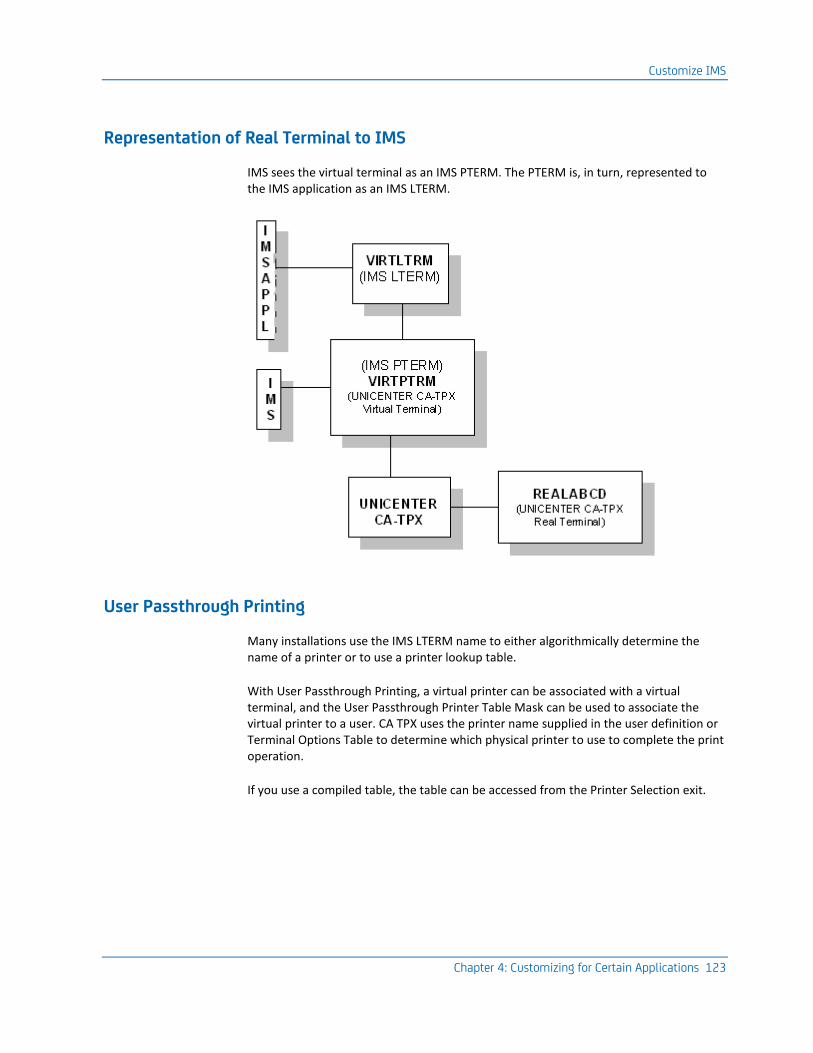
Customize IMS
Chapter 4: Customizing for Certain Applications 123
Representation of Real Terminal to IMS
IMS sees the virtual terminal as an IMS PTERM. The PTERM is, in turn, represented to the IMS application as an IMS LTERM.
User Passthrough Printing
Many installations use the IMS LTERM name to either algorithmically determine the name of a printer or to use a printer lookup table.
With User Passthrough Printing, a virtual printer can be associated with a virtual terminal, and the User Passthrough Printer Table Mask can be used to associate the virtual printer to a user. CA TPX uses the printer name supplied in the user definition or Terminal Options Table to determine which physical printer to use to complete the print operation.
If you use a compiled table, the table can be accessed from the Printer Selection exit.
Customize the IBM Information Network
124 Programming Guide
Customize the IBM Information Network
The IBM Information Network is also known as the IBM Managed Network Service, IBMLINK, IBMINFO, and IN.
Note: If you receive a SENSE087D0001 code while trying to access the IBM Information Network from this product, you are probably using a virtual terminal name that another IBM Information Network user (at a different site) is using. To solve the problem, use unique names for your virtual terminals. For more information about defining virtual terminal names, see Customize the APTPX Member (see page 68).
SESSLIM=YES is required in unique ACB definitions.
Create an Application Definition
The Information Service Manager of the IBM Information Network issues CLSDST PASS when a service is requested. Because the target APPLID can be any name, you must specify UNQ in the Type field of the ACT.
If you want the startup ACL to communicate with the Information Services Manager, specify Y in the Start ACL prior to CLSDST PASS field of the ACT.
SIMLOGON
In Technical Bulletin #8710, IBM reports changes to the handling of simulated terminals by their Information Network. The two main effects of the changes are:
■ To remove the SIMLOGON BIND that was used to return users to the Information Service Manager Menu. Users are now returned to the Menu.
■ To introduce an extra CLSDST PASS into the process of connecting from the Service Manager to an application.
This only affects this product if you are accessing applications that issue CLSDST PASS (for example, TSO). If you are accessing these types of applications, you must inform the IBM Information Network to define your virtual terminals as passthrough ANTs.
User Passthrough Printing
If you access any services that allow you to print information to the user's printer, you may want to utilize User Passthrough Printing to route the print request to the user's physical printer. For more information, see the Administration Guide.
Customize Netview/NCCF
Chapter 4: Customizing for Certain Applications 125
Customize Netview/NCCF
If you want to use Netview/NCCF with this product, you must follow the procedure in this section for creating the application definition for Netview/NCCF.
Create an Application Definition
To create an application definition for Netview/NCCF
1. Specify GRP in the Type field of the ACT.
2. Specify Y in the Issues CLSDST PASS field of the ACT.
3. Specify a substring in the Substring field of the ACT.
Tailor Netview/NCCF for CA TPX
Netview/NCCF permits two methods for defining terminals. Both methods require you to specify certain statements in the DSIDMN member of DSIPARM. You can explicitly define terminals using POS statements such as this:
label POS terminal,terminal,...
If you like, you can use the POSPOOL statement such as the following to reserve a pool of entries that any terminal can use:
label POSPOOL n
Netview/NCCF only allows one user ID to receive unsolicited VTAM messages. For each message, Netview searches its ASSIGN tables, the POS table, and the POSPOOL in that order. The message goes to the first terminal with a user ID and associated profile that has the value YES on the MSGRECVR parameter.
Customize NetSpy
The NetSpy Network Performance product from CA contains specific support for CA TPX. When used with this product, NetSpy can associate real and virtual terminals together and thus report the correct response time for each application and associated real terminals.
To indicate that you want to use NetSpy, specify Y in the Activate NetSpy Interface field of the System Options Table.
Customize TCAM
126 Programming Guide
Create an Application Definition
Because current releases of NetSpy require the use of a group virtual terminal, you must specify GRP in the Type field of the ACT. You should also specify Y in the Sends first screen field of the ACT.
Define CA TPX to NetSpy
To define this product to NetSpy, include the following statement in the NetSpy initialization parameters:
APPL=tpx-applid,SMANAGER=TPX
Customize TCAM
Although CA TPX is not a TCAM application program, it can be used with TCAM applications if you have both VTAM and TCAM installed. This is true with TCAM V3, which uses VTAM for all terminal activity.
Terminal Definitions
As far as TCAM is concerned, the virtual terminals are just like any SNA terminal in another domain.
Customize TSO
This section discusses tailoring TSO to work with CA TPX.
Create an Application Definition
You can create an application definition for TSO.
To create an application definition for TSO
1. Specify one of the following in the Type field of the ACT:
GRP
Specify GRP if you want to use the TSO RECONNECT parameter or if you use data in the SessionData field in Session Options in user or profile maintenance to pass data to the application when it is activated. For more information, see TSO RECONNECT (see page 128).
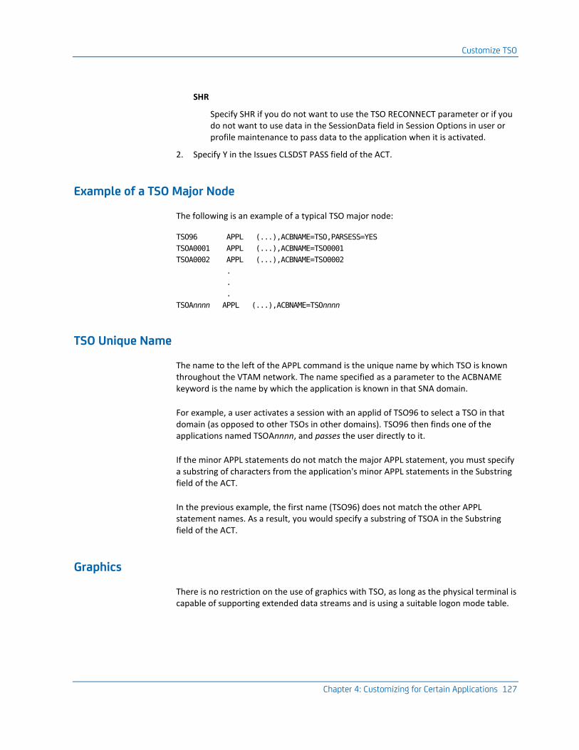
Customize TSO
Chapter 4: Customizing for Certain Applications 127
SHR
Specify SHR if you do not want to use the TSO RECONNECT parameter or if you do not want to use data in the SessionData field in Session Options in user or profile maintenance to pass data to the application when it is activated.
2. Specify Y in the Issues CLSDST PASS field of the ACT.
Example of a TSO Major Node
The following is an example of a typical TSO major node:
TSO96 APPL (...),ACBNAME=TSO,PARSESS=YES
TSOA0001 APPL (...),ACBNAME=TSO0001
TSOA0002 APPL (...),ACBNAME=TSO0002
.
.
.
TSOAnnnn APPL (...),ACBNAME=TSOnnnn
TSO Unique Name
The name to the left of the APPL command is the unique name by which TSO is known throughout the VTAM network. The name specified as a parameter to the ACBNAME keyword is the name by which the application is known in that SNA domain.
For example, a user activates a session with an applid of TSO96 to select a TSO in that domain (as opposed to other TSOs in other domains). TSO96 then finds one of the applications named TSOAnnnn, and passes the user directly to it.
If the minor APPL statements do not match the major APPL statement, you must specify a substring of characters from the application's minor APPL statements in the Substring field of the ACT.
In the previous example, the first name (TSO96) does not match the other APPL statement names. As a result, you would specify a substring of TSOA in the Substring field of the ACT.
Graphics
There is no restriction on the use of graphics with TSO, as long as the physical terminal is capable of supporting extended data streams and is using a suitable logon mode table.
Customize VSPC
128 Programming Guide
TSO RECONNECT
Under some circumstances, such as a network error, the user's terminal can be disconnected from its associated address space. In this situation a user can be reconnected to the existing address space by using the RECONNECT parameter in the LOGON request.
TSO initially ignores the RECONNECT parameter and selects an unused ACB to process the initial logon. The original ACB is still disconnected. After the user's identity is validated, the newly selected ACB attempts to pass the session back to the original ACB.
If you specified SHR in the Type field in the ACT, it is possible to get another user's address space.
SessionData Field
The problem that affects the use of the RECONNECT parameter can also occur if the user ID has been entered in the SessionData field in Application Session Options in user or profile maintenance. Therefore, do not use the SessionData field if you have specified SHR in the Type field in the ACT.
Customize VSPC
VSPC uses one VTAM ACB for validation purposes and another for normal activity. Unlike other applications, VSPC performs the initial security checking with the main task, and the CLSDST PASS takes place during the signon conversation.
Create an Application Definition
To create an application definition for VSPC
1. Specify GRP in the Type field of the ACT.
2. Specify Y in the Issues CLSDST PASS field of the ACT.
3. Specify Y in the Start ACL prior to CLSDST PASS field of the ACT.

Chapter 5: Setting Up User Exits 129
Chapter 5: Setting Up User Exits
CA TPX provides a number of user exits designed to give installation management maximum flexibility in providing the right environment for every end user. This chapter shows you the register contents, entry codes, parameter list, and return codes for each exit. The user exits available to you include:
■ ACB Selection
■ ACL Parameter
■ Command
■ Command Simulation
■ Encrypt/Decrypt
■ Error Processing
■ LOG Writer
■ Logon
■ Menu
■ Print Banner
■ Printer Selection
■ Query Response
■ Queue
■ Receive
■ Route
■ Send
■ Session Initiation/Termination
■ Signon and Signoff
■ Switch-in

Customize VSPC
130 Programming Guide
■ Timeout Option Override
■ View Security Access
Note: CA supports only the parameters and return codes associated with these exits. You are responsible for coding and debugging your own exits that use these parameters and return codes.
This section contains the following topics:
Assemble the Exits (see page 131) Prerequisites (see page 131) System Options Table (SMRT) Values (see page 131) 31-bit Addressing Mode (see page 131) Generate Trace Entries (see page 132) Reentrant Programs (see page 132) Boundary Alignment (see page 133) Communicate with a User from an Exit Routine (see page 133) Issue a Command from an Exit Routine (see page 136) ACB Selection Exit (see page 137) ACL Parameter Exit (see page 139) Command Exit (see page 141) Command Simulation Exit (see page 144) Encrypt/Decrypt Exit (see page 145) Error Processing Exit (see page 146) LOG Writer Exit (see page 147) Logon Exit (see page 148) Mail Exit (see page 151) Menu Exit (see page 158) Print Banner Exit (see page 160) Printer Selection Exit (see page 163) Query Response Exit (see page 164) Queue Exit (see page 166) Receive Exit (see page 168) Route Exit (see page 170) Send Exit (see page 173) Session Initiation/Termination Exit (see page 174) Signon and Signoff Exit (see page 176) Switch-in Exit (see page 189) Timeout Option Override Exit (see page 191) View Security Access User Exit (see page 194)
Assemble the Exits
Chapter 5: Setting Up User Exits 131
Assemble the Exits
To assemble the exits, you can use the JCL in the ASMUXIT member of the CB0VSRC library.
When customizing TPX user exits, it is recommended that you create a site-specific version of the exit source and leave the original source in the CBOVSRC dataset unchanged.
The customized exit should be assembled with the correct exit name and placed in a separate load library that is defined on the TPX proc '//STEPLIB DD' statement concatenated in front of the TPX product load library.
TPX will need to be cycled for new or modified exits to become active.
Prerequisites
Before you start setting up the user exits described in this chapter, you should familiarize yourself with the programming notes in the following sections.
System Options Table (SMRT) Values
In every exit, the main control block (the SMRT) is passed in register 11 (R11). If you use any supplied macros, you must ensure that the R11 value remains intact.
How to Access SMRT Values
A user interested in any of the SMRT values can access them using the SMRT macro as follows:
USING SMRT,R11
:
SMRT TYPE=DSECT
Important! Do not attempt to influence processing by adjusting the SMRT. In most cases this will lead to abends and in others will cause unpredictable results.
31-bit Addressing Mode
All exit routines are entered in 31-bit addressing mode unless otherwise noted. Two macros are available to simplify changing the addressing mode. XASET24 switches the addressing mode to 24 bit, and XASET31 switches the addressing mode to 31 bit.

Generate Trace Entries
132 Programming Guide
How the Operating System Is Determined
These macros reference the SMRT to which R11 points to determine the level of the operating system before issuing the appropriate instructions.
Generate Trace Entries
You can generate entries for exit programs by using the UENTER and UEXIT macros distributed in the CB0VMAC. When you turn on any trace, including module entries, trace entries appear for any executed exit that has been assembled with the UENTER and UEXIT macros. The trace shows the registers and parameters on entry and exit.
To use the UENTER and UEXIT macros without tracing exit programs, specify TRACE=NO in the macros.
Reentrant Programs
You must write the exits as reentrant programs. The UENTER and UEXIT macros are available to help you write these programs. The UENTER macro acquires a save area and optionally acquires a work area. The UEXIT macro frees the work area and save area and returns to CA TPX.
If You Do Not Want a Work Area
If you do not want a work area, code the UENTER/UEXIT macros as follows:
UENTER PRGNAME=name
:
L R15,retcode
UEXIT
To Acquire a Work Area
To acquire a work area, code the UENTER/UEXIT macros as follows:
UENTER PRGNAME=name,
DATAREA=dname,
DATLEN=dlen
:
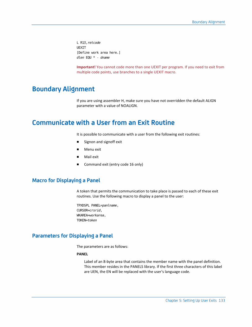
Boundary Alignment
Chapter 5: Setting Up User Exits 133
L R15,retcode
UEXIT
[Define work area here.]
dlen EQU * - dname
Important! You cannot code more than one UEXIT per program. If you need to exit from multiple code points, use branches to a single UEXIT macro.
Boundary Alignment
If you are using assembler H, make sure you have not overridden the default ALIGN parameter with a value of NOALIGN.
Communicate with a User from an Exit Routine
It is possible to communicate with a user from the following exit routines:
■ Signon and signoff exit
■ Menu exit
■ Mail exit
■ Command exit (entry code 16 only)
Macro for Displaying a Panel
A token that permits the communication to take place is passed to each of these exit routines. Use the following macro to display a panel to the user:
TPXDSPL PANEL=panlname,
CURSOR=crsrid,
WKAREA=workarea,
TOKEN=token
Parameters for Displaying a Panel
The parameters are as follows:
PANEL
Label of an 8-byte area that contains the member name with the panel definition. This member resides in the PANELS library. If the first three characters of this label are UEN, the EN will be replaced with the user's language code.
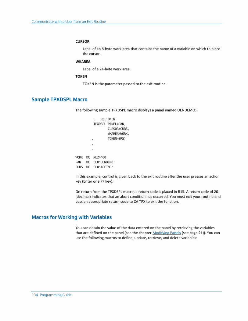
Communicate with a User from an Exit Routine
134 Programming Guide
CURSOR
Label of an 8-byte work area that contains the name of a variable on which to place the cursor.
WKAREA
Label of a 24-byte work area.
TOKEN
TOKEN is the parameter passed to the exit routine.
Sample TPXDSPL Macro
The following sample TPXDSPL macro displays a panel named UENDEMO:
L R5,TOKEN
TPXDSPL PANEL=PAN,
CURSOR=CURS,
WKAREA=WORK,
. TOKEN=(R5)
.
.
WORK DC XL24'00'
PAN DC CL8'UENDEMO'
CURS DC CL8'ACCTNO'
In this example, control is given back to the exit routine after the user presses an action key (Enter or a PF key).
On return from the TPXDSPL macro, a return code is placed in R15. A return code of 20 (decimal) indicates that an abort condition has occurred. You must exit your routine and pass an appropriate return code to CA TPX to exit the function.
Macros for Working with Variables
You can obtain the value of the data entered on the panel by retrieving the variables that are defined on the panel (see the chapter Modifying Panels (see page 21)). You can use the following macros to define, update, retrieve, and delete variables:
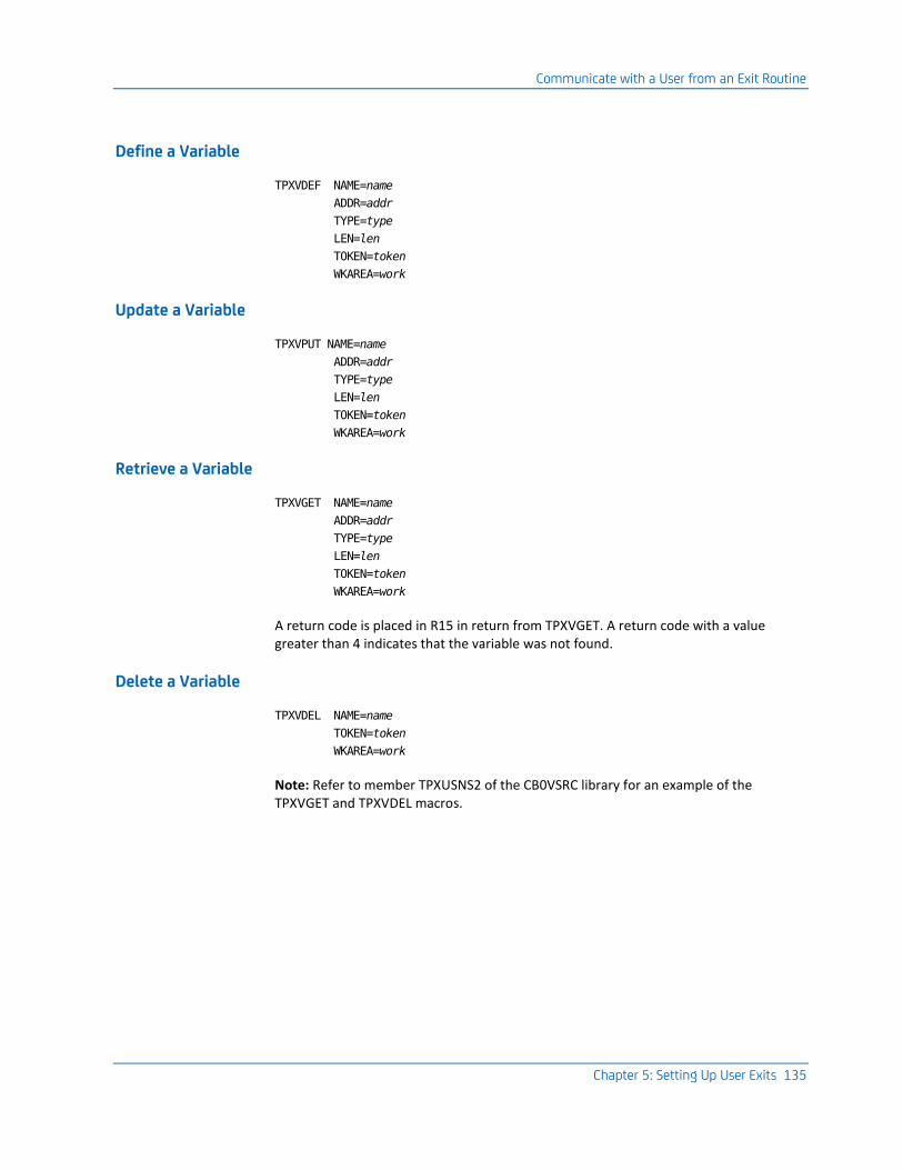
Communicate with a User from an Exit Routine
Chapter 5: Setting Up User Exits 135
Define a Variable
TPXVDEF NAME=name
ADDR=addr
TYPE=type
LEN=len
TOKEN=token
WKAREA=work
Update a Variable
TPXVPUT NAME=name
ADDR=addr
TYPE=type
LEN=len
TOKEN=token
WKAREA=work
Retrieve a Variable
TPXVGET NAME=name
ADDR=addr
TYPE=type
LEN=len
TOKEN=token
WKAREA=work
A return code is placed in R15 in return from TPXVGET. A return code with a value greater than 4 indicates that the variable was not found.
Delete a Variable
TPXVDEL NAME=name
TOKEN=token
WKAREA=work
Note: Refer to member TPXUSNS2 of the CB0VSRC library for an example of the TPXVGET and TPXVDEL macros.
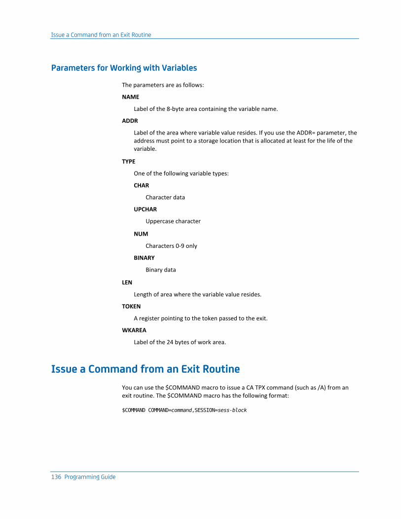
Issue a Command from an Exit Routine
136 Programming Guide
Parameters for Working with Variables
The parameters are as follows:
NAME
Label of the 8-byte area containing the variable name.
ADDR
Label of the area where variable value resides. If you use the ADDR= parameter, the address must point to a storage location that is allocated at least for the life of the variable.
TYPE
One of the following variable types:
CHAR
Character data
UPCHAR
Uppercase character
NUM
Characters 0-9 only
BINARY
Binary data
LEN
Length of area where the variable value resides.
TOKEN
A register pointing to the token passed to the exit.
WKAREA
Label of the 24 bytes of work area.
Issue a Command from an Exit Routine
You can use the $COMMAND macro to issue a CA TPX command (such as /A) from an exit routine. The $COMMAND macro has the following format:
$COMMAND COMMAND=command,SESSION=sess-block
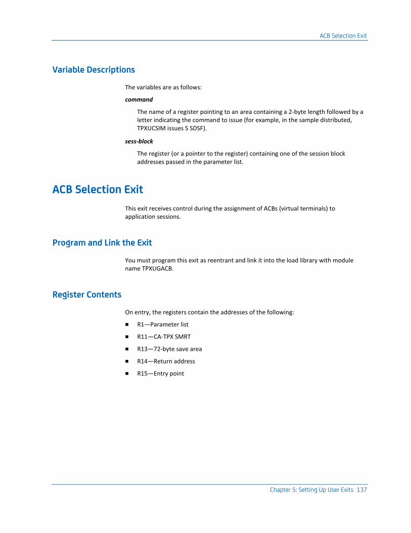
ACB Selection Exit
Chapter 5: Setting Up User Exits 137
Variable Descriptions
The variables are as follows:
command
The name of a register pointing to an area containing a 2-byte length followed by a letter indicating the command to issue (for example, in the sample distributed, TPXUCSIM issues S SDSF).
sess-block
The register (or a pointer to the register) containing one of the session block addresses passed in the parameter list.
ACB Selection Exit
This exit receives control during the assignment of ACBs (virtual terminals) to application sessions.
Program and Link the Exit
You must program this exit as reentrant and link it into the load library with module name TPXUGACB.
Register Contents
On entry, the registers contain the addresses of the following:
■ R1—Parameter list
■ R11—CA-TPX SMRT
■ R13—72-byte save area
■ R14—Return address
■ R15—Entry point

ACB Selection Exit
138 Programming Guide
Entry Codes
Register 0 has the following entry code:
0
Entered once at startup.
12
Entered at session initiation after a new ACB assignment.
16
Entered once at shutdown.
20
Entered at session end just before ACB freeing.
24
Entered at session initiation before ACB assignment.
Parameter List
The parameter list varies by entry code:
0
None
12
Entry code 12 provides the following parameter list:
+0
Address of user ID
+4
Address of session ID
+8
Address of ACB-name
+12
Address of ACT entry for the application

ACL Parameter Exit
Chapter 5: Setting Up User Exits 139
16
None
20
Same as code 12
24
Same as code 12
Return Codes
The return code has significance only for entry codes 20 and 24. For entry code 20, a nonzero return code signals this product not to free the ACB. For entry code 24, a nonzero return code indicates that the exit has rejected the ACB assignment.
ACL Parameter Exit
This exit gains control each time the product encounters an ampersand in either the operand of an ACL/E statement or the value of the session data parameter. It allows you to create unique variable symbols for ACL/E.
Program and Link the Exit
You must program this exit as reentrant and link it into the load library with module name TPXUPSYM.
Entry Codes
On entry, the registers contain the addresses of the following:
■ R1—Parameter list
■ R11—SMRT
■ R13—72-byte save area
■ R14—Return address
■ R15—Entry point
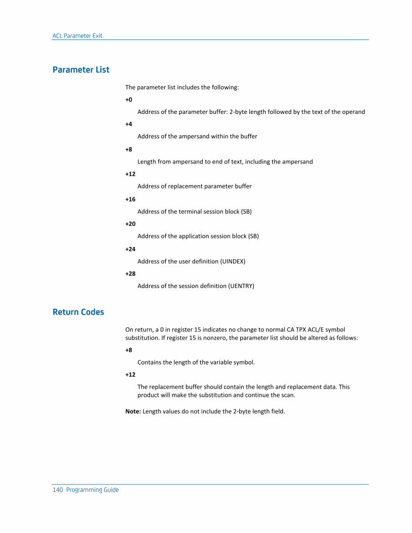
ACL Parameter Exit
140 Programming Guide
Parameter List
The parameter list includes the following:
+0
Address of the parameter buffer: 2-byte length followed by the text of the operand
+4
Address of the ampersand within the buffer
+8
Length from ampersand to end of text, including the ampersand
+12
Address of replacement parameter buffer
+16
Address of the terminal session block (SB)
+20
Address of the application session block (SB)
+24
Address of the user definition (UINDEX)
+28
Address of the session definition (UENTRY)
Return Codes
On return, a 0 in register 15 indicates no change to normal CA TPX ACL/E symbol substitution. If register 15 is nonzero, the parameter list should be altered as follows:
+8
Contains the length of the variable symbol.
+12
The replacement buffer should contain the length and replacement data. This product will make the substitution and continue the scan.
Note: Length values do not include the 2-byte length field.
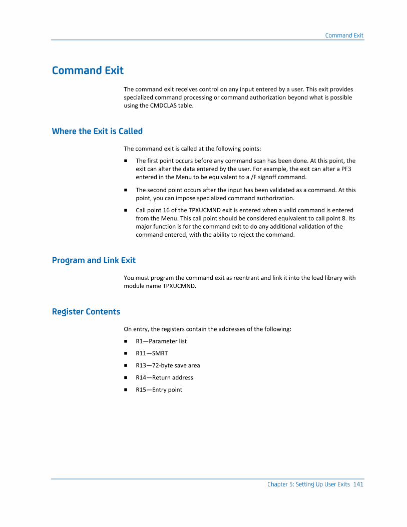
Command Exit
Chapter 5: Setting Up User Exits 141
Command Exit
The command exit receives control on any input entered by a user. This exit provides specialized command processing or command authorization beyond what is possible using the CMDCLAS table.
Where the Exit is Called
The command exit is called at the following points:
■ The first point occurs before any command scan has been done. At this point, the exit can alter the data entered by the user. For example, the exit can alter a PF3 entered in the Menu to be equivalent to a /F signoff command.
■ The second point occurs after the input has been validated as a command. At this point, you can impose specialized command authorization.
■ Call point 16 of the TPXUCMND exit is entered when a valid command is entered from the Menu. This call point should be considered equivalent to call point 8. Its major function is for the command exit to do any additional validation of the command entered, with the ability to reject the command.
Program and Link Exit
You must program the command exit as reentrant and link it into the load library with module name TPXUCMND.
Register Contents
On entry, the registers contain the addresses of the following:
■ R1—Parameter list
■ R11—SMRT
■ R13—72-byte save area
■ R14—Return address
■ R15—Entry point
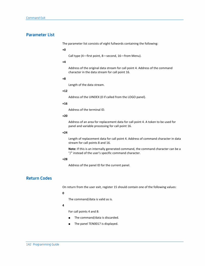
Command Exit
142 Programming Guide
Parameter List
The parameter list consists of eight fullwords containing the following:
+0
Call type (4—first point, 8—second, 16—from Menu).
+4
Address of the original data stream for call point 4. Address of the command character in the data stream for call point 16.
+8
Length of the data stream.
+12
Address of the UINDEX (0 if called from the LOGO panel).
+16
Address of the terminal ID.
+20
Address of an area for replacement data for call point 4. A token to be used for panel and variable processing for call point 16.
+24
Length of replacement data for call point 4. Address of command character in data stream for call points 8 and 16.
Note: If this is an internally generated command, the command character can be a "/" instead of the user's specific command character.
+28
Address of the panel ID for the current panel.
Return Codes
On return from the user exit, register 15 should contain one of the following values:
0
The command/data is valid as is.
4
For call points 4 and 8:
■ The command/data is discarded.
■ The panel TEN0017 is displayed.
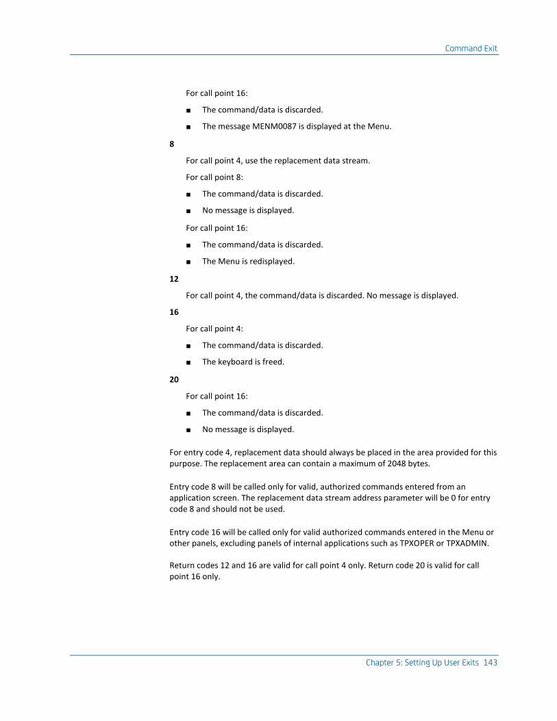
Command Exit
Chapter 5: Setting Up User Exits 143
For call point 16:
■ The command/data is discarded.
■ The message MENM0087 is displayed at the Menu.
8
For call point 4, use the replacement data stream.
For call point 8:
■ The command/data is discarded.
■ No message is displayed.
For call point 16:
■ The command/data is discarded.
■ The Menu is redisplayed.
12
For call point 4, the command/data is discarded. No message is displayed.
16
For call point 4:
■ The command/data is discarded.
■ The keyboard is freed.
20
For call point 16:
■ The command/data is discarded.
■ No message is displayed.
For entry code 4, replacement data should always be placed in the area provided for this purpose. The replacement area can contain a maximum of 2048 bytes.
Entry code 8 will be called only for valid, authorized commands entered from an application screen. The replacement data stream address parameter will be 0 for entry code 8 and should not be used.
Entry code 16 will be called only for valid authorized commands entered in the Menu or other panels, excluding panels of internal applications such as TPXOPER or TPXADMIN.
Return codes 12 and 16 are valid for call point 4 only. Return code 20 is valid for call point 16 only.
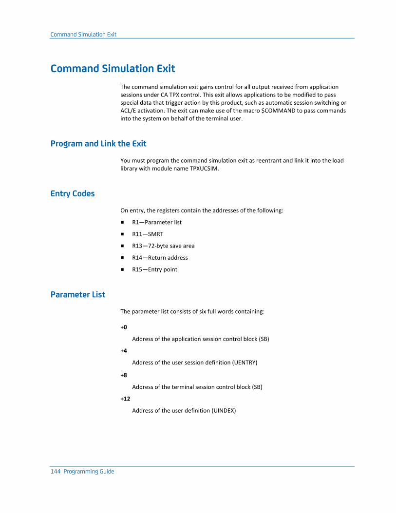
Command Simulation Exit
144 Programming Guide
Command Simulation Exit
The command simulation exit gains control for all output received from application sessions under CA TPX control. This exit allows applications to be modified to pass special data that trigger action by this product, such as automatic session switching or ACL/E activation. The exit can make use of the macro $COMMAND to pass commands into the system on behalf of the terminal user.
Program and Link the Exit
You must program the command simulation exit as reentrant and link it into the load library with module name TPXUCSIM.
Entry Codes
On entry, the registers contain the addresses of the following:
■ R1—Parameter list
■ R11—SMRT
■ R13—72-byte save area
■ R14—Return address
■ R15—Entry point
Parameter List
The parameter list consists of six full words containing:
+0
Address of the application session control block (SB)
+4
Address of the user session definition (UENTRY)
+8
Address of the terminal session control block (SB)
+12
Address of the user definition (UINDEX)
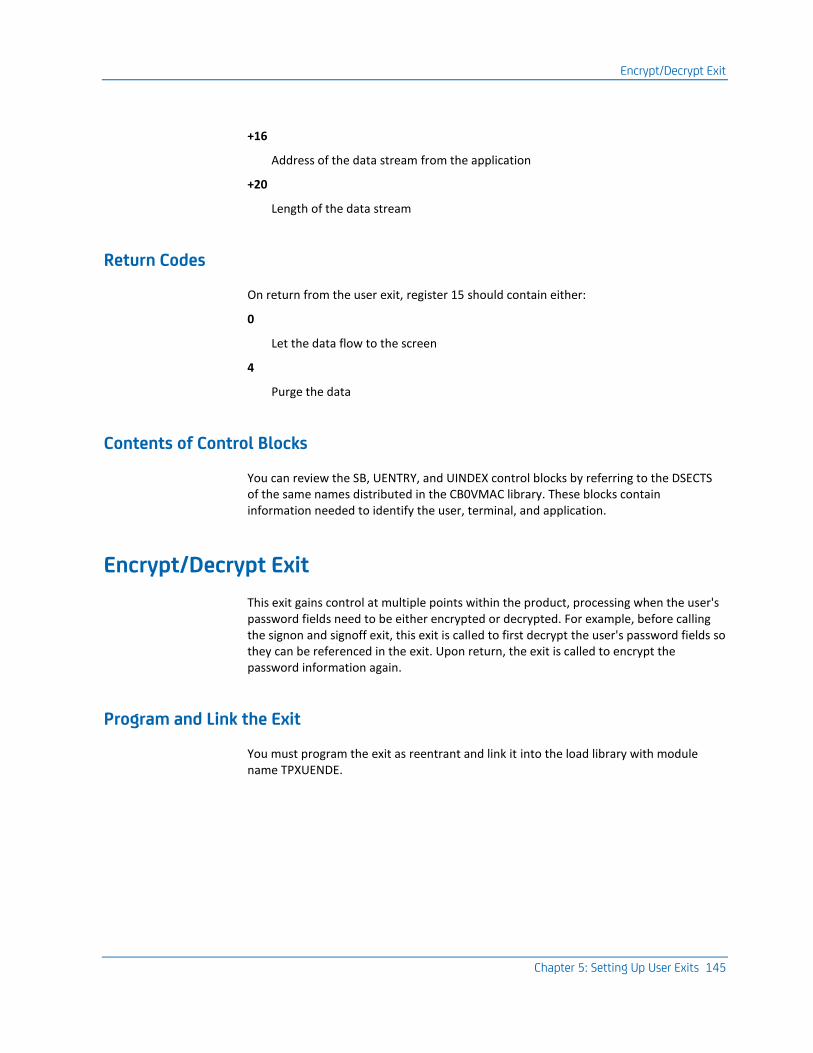
Encrypt/Decrypt Exit
Chapter 5: Setting Up User Exits 145
+16
Address of the data stream from the application
+20
Length of the data stream
Return Codes
On return from the user exit, register 15 should contain either:
0
Let the data flow to the screen
4
Purge the data
Contents of Control Blocks
You can review the SB, UENTRY, and UINDEX control blocks by referring to the DSECTS of the same names distributed in the CB0VMAC library. These blocks contain information needed to identify the user, terminal, and application.
Encrypt/Decrypt Exit
This exit gains control at multiple points within the product, processing when the user's password fields need to be either encrypted or decrypted. For example, before calling the signon and signoff exit, this exit is called to first decrypt the user's password fields so they can be referenced in the exit. Upon return, the exit is called to encrypt the password information again.
Program and Link the Exit
You must program the exit as reentrant and link it into the load library with module name TPXUENDE.
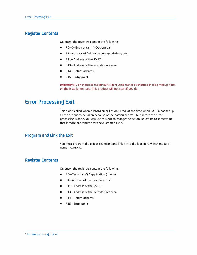
Error Processing Exit
146 Programming Guide
Register Contents
On entry, the registers contain the following:
■ R0—0=Encrypt call 4=Decrypt call
■ R1—Address of field to be encrypted/decrypted
■ R11—Address of the SMRT
■ R13—Address of the 72-byte save area
■ R14—Return address
■ R15—Entry point
Important! Do not delete the default exit routine that is distributed in load module form on the installation tape. This product will not start if you do.
Error Processing Exit
This exit is called when a VTAM error has occurred, at the time when CA TPX has set up all the actions to be taken because of the particular error, but before the error processing is done. You can use this exit to change the action indicators to some value that is more appropriate for the customer's site.
Program and Link the Exit
You must program the exit as reentrant and link it into the load library with module name TPXUERR1.
Register Contents
On entry, the registers contain the following:
■ R0—Terminal (0) / application (4) error
■ R1—Address of the parameter List
■ R11—Address of the SMRT
■ R13—Address of the 72-byte save area
■ R14—Return address
■ R15—Entry point

LOG Writer Exit
Chapter 5: Setting Up User Exits 147
Parameter List
The parameter list consists of the following:
+0
Address of RPL.
+4
Address of user ID that error has occurred for.
+8
Address of the terminal name for terminal error or the address of the application name for Application error.
+12
Address of 4 action indicator bytes that the user can change.
Action Indicator Bits
The DSECT that maps out what each action indicator bit means is distributed in member TPXUERR1 of the CB0VSRC library. This is the sample error processing exit and contains the DSECT.
LOG Writer Exit
This exit is called by the writer task after a LOG message has been formatted but before it has been written to the LOG DD. The exit could selectively write the message to the console or tell CA TPX to discard the message.
Important! Discarding messages generated by CA TPX could eliminate vital information for Technical Support when debugging a problem. Use this carefully.
Program and Link the Exit
You must program the exit as reentrant and link it into the load library with module name TPXULOGW.
Logon Exit
148 Programming Guide
TPX--LOG Writer Exit--Register Contents
On entry, the registers contain the addresses of the following:
■ R1—Parameter list pointer
■ R11—SMRT address
■ R13—72-byte save area
■ R14—Return address
■ R15—Entry point
Return Codes
On exit, the value in register 15 determines what processing should take place. The following lists the results for each possible value of register 15:
0
Normal processing
4
Discard the LOG message
Logon Exit
The logon exit gains control whenever an end user logs on to CA TPX. This occurs either when the terminal is "logappl'd" to the application or a user enters the appropriate VTAM command to access the application. The logon exit allows an installation to select from among several different Logo panel images based upon terminal address. The exit can also set several other processing options for the particular terminal.
Program and Link the Exit
You must program the logon exit as reentrant and link it into the TPXload library with module name TPXULOGN.

Logon Exit
Chapter 5: Setting Up User Exits 149
Register Contents
On entry, the registers contain the addresses of the following:
■ R1—Parameter list
■ R11—SMRT
■ R13—72-byte save area
■ R14—Return address
■ R15—Entry point
Parameter List
The parameter list consists of eight fullwords containing:
+0
Address of the 8-byte terminal ID
+4
Address of a 1-byte reserved field
+8
Address of the CINIT RU
+12
Length of the CINIT RU
+16
Address of 32 bytes of user data from logon
Note: If the user's terminal has the terminal option field Terminal defined to VTAM with INTTAB set to Y, this address will contain nulls.
+20
Address of a 1-byte option field
+24
Address of a halfword attention interval
+28
Address of an 8-byte area to request a logo
Logon Exit
150 Programming Guide
Return Codes
On return from the user exit, register 15 should contain either of the following:
0
Continue logon
4
Abort logon
Option Field Values
The option byte can be set with the following values to select specialized processing based on terminal ID:
X'80'
Always compress data streams to the terminal.
X'40'
Never compress data streams to the terminal.
X'20'
Always issue read partition query command at logon.
X'10'
Treat user as ACCESS=PASS user only.
X'02'
Release terminal if requested by another application.
X'01'
Reacquire terminal if ACCESS=PASS user.
Logo Name
You should set the logo name with the name of a member in the data set referenced by the //PANELS DD statement in the procedure.
Attention Interval
The attention interval is the number of seconds in which CA TPX will look for a second attention before processing the first.
Mail Exit
Chapter 5: Setting Up User Exits 151
Terminal Options Table
Some of the specialized processing can be defined in the Terminal Options Table. For more information, see the Administration Guide.
Mail Exit
This exit is used to control the Mail facility, both on-line and when Batch administration is used to update mail messages and bulletins.
Program and Link the Exit
You must program the exit as reentrant and link it into the load library with module name TPXUMAIL.
Important! In developing your exit, remember that after closing a QSAM DCB the buffer pool is not released and will be reused only if the same copy of the DCB is reopened. Continuously opening a fresh copy of a DCB without the use of FREEPOOL at close will exhaust user memory space. Similarly, if you reuse a DCB with different attributes, a FREEPOOL is recommended.
Call Points
The following table lists the call points for the TPXUMAIL exit:
0
A send request has been issued.
4
A message is about to be sent to a recipient.
8
A message is about to be saved for a recipient.
12
The send request has been issued and the recipient identified. The exit can decide whether the message should be sent or saved.
24
A message is about to be read for the first time.
28
A message or bulletin is about to be deleted.
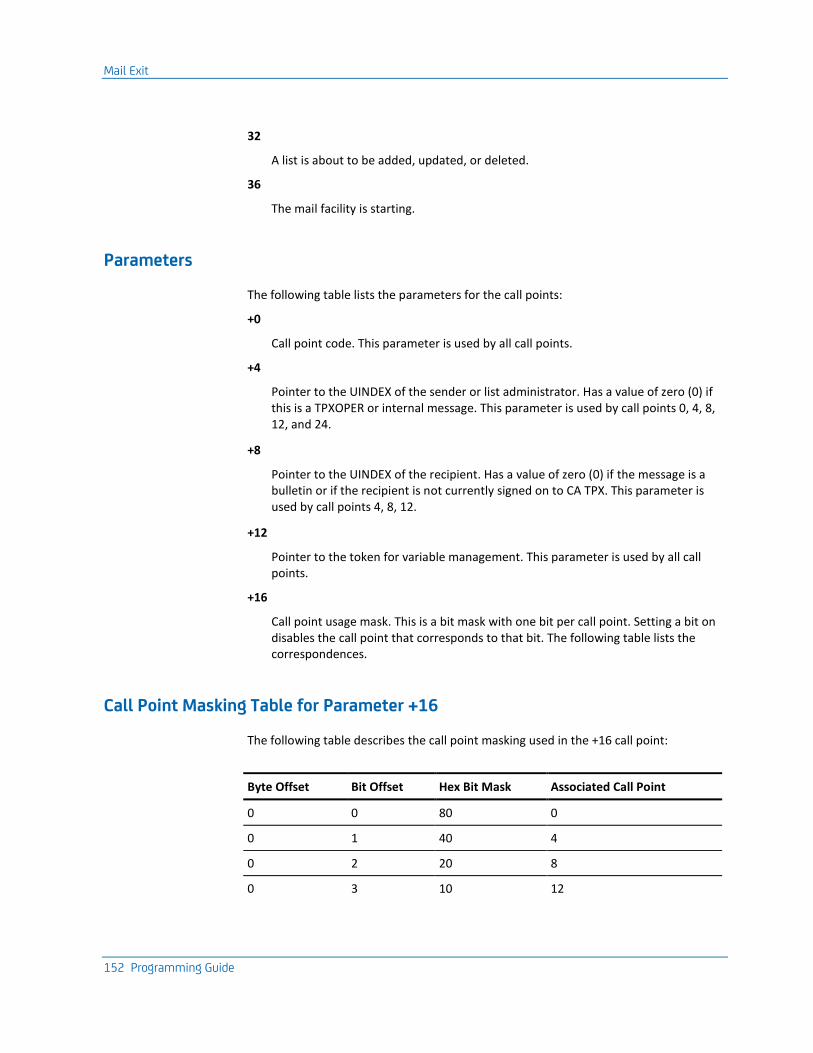
Mail Exit
152 Programming Guide
32
A list is about to be added, updated, or deleted.
36
The mail facility is starting.
Parameters
The following table lists the parameters for the call points:
+0
Call point code. This parameter is used by all call points.
+4
Pointer to the UINDEX of the sender or list administrator. Has a value of zero (0) if this is a TPXOPER or internal message. This parameter is used by call points 0, 4, 8, 12, and 24.
+8
Pointer to the UINDEX of the recipient. Has a value of zero (0) if the message is a bulletin or if the recipient is not currently signed on to CA TPX. This parameter is used by call points 4, 8, 12.
+12
Pointer to the token for variable management. This parameter is used by all call points.
+16
Call point usage mask. This is a bit mask with one bit per call point. Setting a bit on disables the call point that corresponds to that bit. The following table lists the correspondences.
Call Point Masking Table for Parameter +16
The following table describes the call point masking used in the +16 call point:
Byte Offset Bit Offset Hex Bit Mask Associated Call Point
0 0 80 0
0 1 40 4
0 2 20 8
0 3 10 12
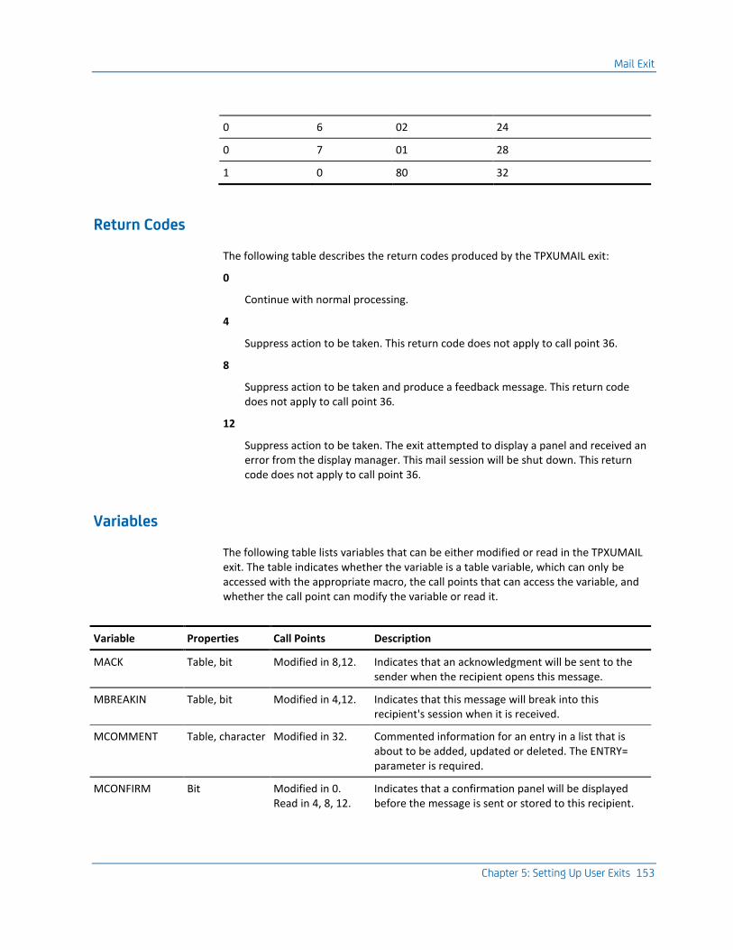
Mail Exit
Chapter 5: Setting Up User Exits 153
0 6 02 24
0 7 01 28
1 0 80 32
Return Codes
The following table describes the return codes produced by the TPXUMAIL exit:
0
Continue with normal processing.
4
Suppress action to be taken. This return code does not apply to call point 36.
8
Suppress action to be taken and produce a feedback message. This return code does not apply to call point 36.
12
Suppress action to be taken. The exit attempted to display a panel and received an error from the display manager. This mail session will be shut down. This return code does not apply to call point 36.
Variables
The following table lists variables that can be either modified or read in the TPXUMAIL exit. The table indicates whether the variable is a table variable, which can only be accessed with the appropriate macro, the call points that can access the variable, and whether the call point can modify the variable or read it.
Variable Properties Call Points Description
MACK Table, bit Modified in 8,12. Indicates that an acknowledgment will be sent to the sender when the recipient opens this message.
MBREAKIN Table, bit Modified in 4,12. Indicates that this message will break into this recipient's session when it is received.
MCOMMENT Table, character Modified in 32. Commented information for an entry in a list that is about to be added, updated or deleted. The ENTRY= parameter is required.
MCONFIRM Bit Modified in 0. Read in 4, 8, 12.
Indicates that a confirmation panel will be displayed before the message is sent or stored to this recipient.
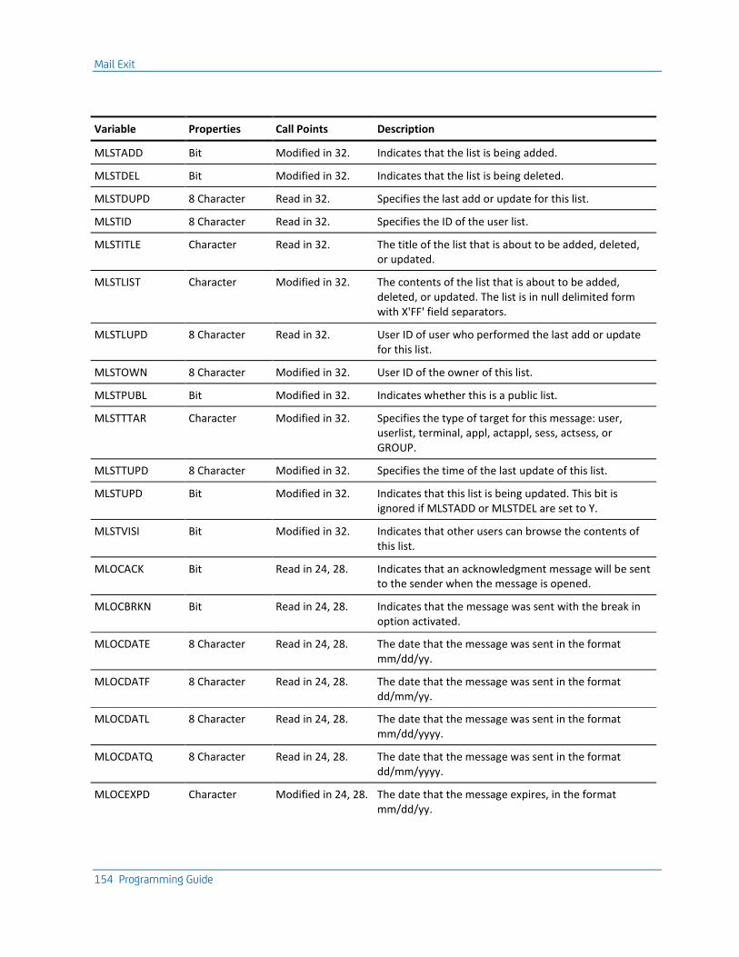
Mail Exit
154 Programming Guide
Variable Properties Call Points Description
MLSTADD Bit Modified in 32. Indicates that the list is being added.
MLSTDEL Bit Modified in 32. Indicates that the list is being deleted.
MLSTDUPD 8 Character Read in 32. Specifies the last add or update for this list.
MLSTID 8 Character Read in 32. Specifies the ID of the user list.
MLSTITLE Character Read in 32. The title of the list that is about to be added, deleted, or updated.
MLSTLIST Character Modified in 32. The contents of the list that is about to be added, deleted, or updated. The list is in null delimited form with X'FF' field separators.
MLSTLUPD 8 Character Read in 32. User ID of user who performed the last add or update for this list.
MLSTOWN 8 Character Modified in 32. User ID of the owner of this list.
MLSTPUBL Bit Modified in 32. Indicates whether this is a public list.
MLSTTTAR Character Modified in 32. Specifies the type of target for this message: user, userlist, terminal, appl, actappl, sess, actsess, or GROUP.
MLSTTUPD 8 Character Modified in 32. Specifies the time of the last update of this list.
MLSTUPD Bit Modified in 32. Indicates that this list is being updated. This bit is ignored if MLSTADD or MLSTDEL are set to Y.
MLSTVISI Bit Modified in 32. Indicates that other users can browse the contents of this list.
MLOCACK Bit Read in 24, 28. Indicates that an acknowledgment message will be sent to the sender when the message is opened.
MLOCBRKN Bit Read in 24, 28. Indicates that the message was sent with the break in option activated.
MLOCDATE 8 Character Read in 24, 28. The date that the message was sent in the format mm/dd/yy.
MLOCDATF 8 Character Read in 24, 28. The date that the message was sent in the format dd/mm/yy.
MLOCDATL 8 Character Read in 24, 28. The date that the message was sent in the format mm/dd/yyyy.
MLOCDATQ 8 Character Read in 24, 28. The date that the message was sent in the format dd/mm/yyyy.
MLOCEXPD Character Modified in 24, 28. The date that the message expires, in the format mm/dd/yy.
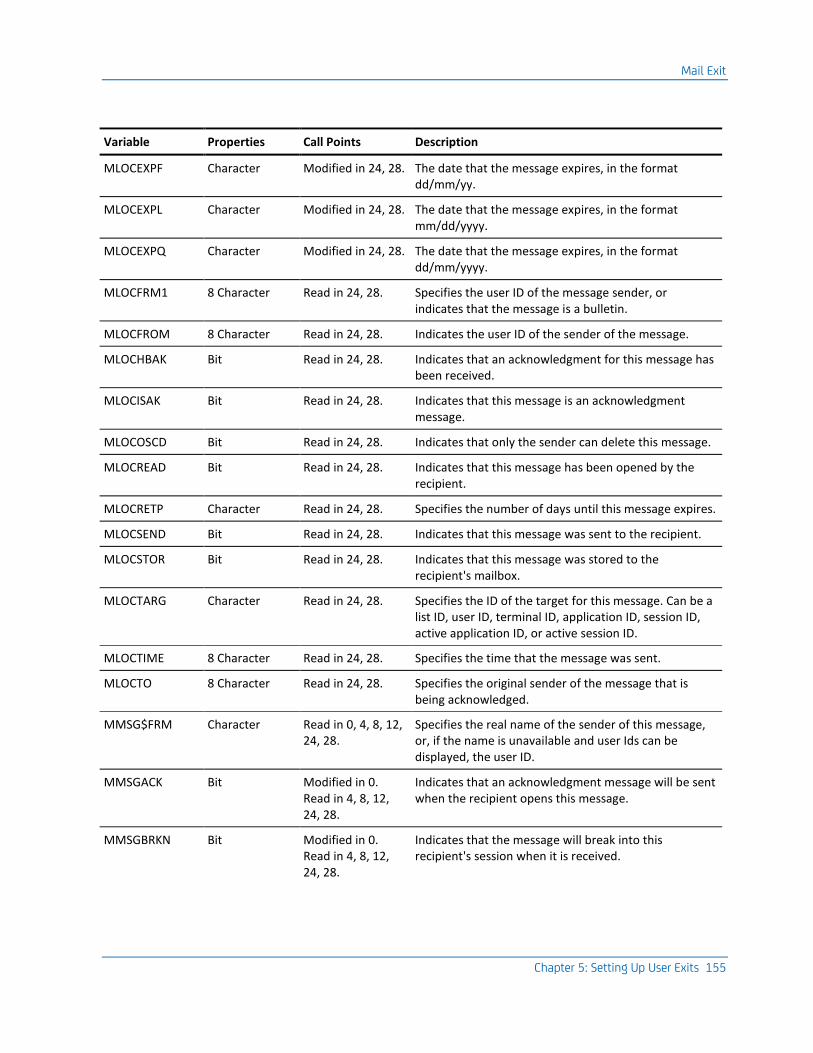
Mail Exit
Chapter 5: Setting Up User Exits 155
Variable Properties Call Points Description
MLOCEXPF Character Modified in 24, 28. The date that the message expires, in the format dd/mm/yy.
MLOCEXPL Character Modified in 24, 28. The date that the message expires, in the format mm/dd/yyyy.
MLOCEXPQ Character Modified in 24, 28. The date that the message expires, in the format dd/mm/yyyy.
MLOCFRM1 8 Character Read in 24, 28. Specifies the user ID of the message sender, or indicates that the message is a bulletin.
MLOCFROM 8 Character Read in 24, 28. Indicates the user ID of the sender of the message.
MLOCHBAK Bit Read in 24, 28. Indicates that an acknowledgment for this message has been received.
MLOCISAK Bit Read in 24, 28. Indicates that this message is an acknowledgment message.
MLOCOSCD Bit Read in 24, 28. Indicates that only the sender can delete this message.
MLOCREAD Bit Read in 24, 28. Indicates that this message has been opened by the recipient.
MLOCRETP Character Read in 24, 28. Specifies the number of days until this message expires.
MLOCSEND Bit Read in 24, 28. Indicates that this message was sent to the recipient.
MLOCSTOR Bit Read in 24, 28. Indicates that this message was stored to the recipient's mailbox.
MLOCTARG Character Read in 24, 28. Specifies the ID of the target for this message. Can be a list ID, user ID, terminal ID, application ID, session ID, active application ID, or active session ID.
MLOCTIME 8 Character Read in 24, 28. Specifies the time that the message was sent.
MLOCTO 8 Character Read in 24, 28. Specifies the original sender of the message that is being acknowledged.
MMSG$FRM Character Read in 0, 4, 8, 12, 24, 28.
Specifies the real name of the sender of this message, or, if the name is unavailable and user Ids can be displayed, the user ID.
MMSGACK Bit Modified in 0. Read in 4, 8, 12, 24, 28.
Indicates that an acknowledgment message will be sent when the recipient opens this message.
MMSGBRKN Bit Modified in 0. Read in 4, 8, 12, 24, 28.
Indicates that the message will break into this recipient's session when it is received.
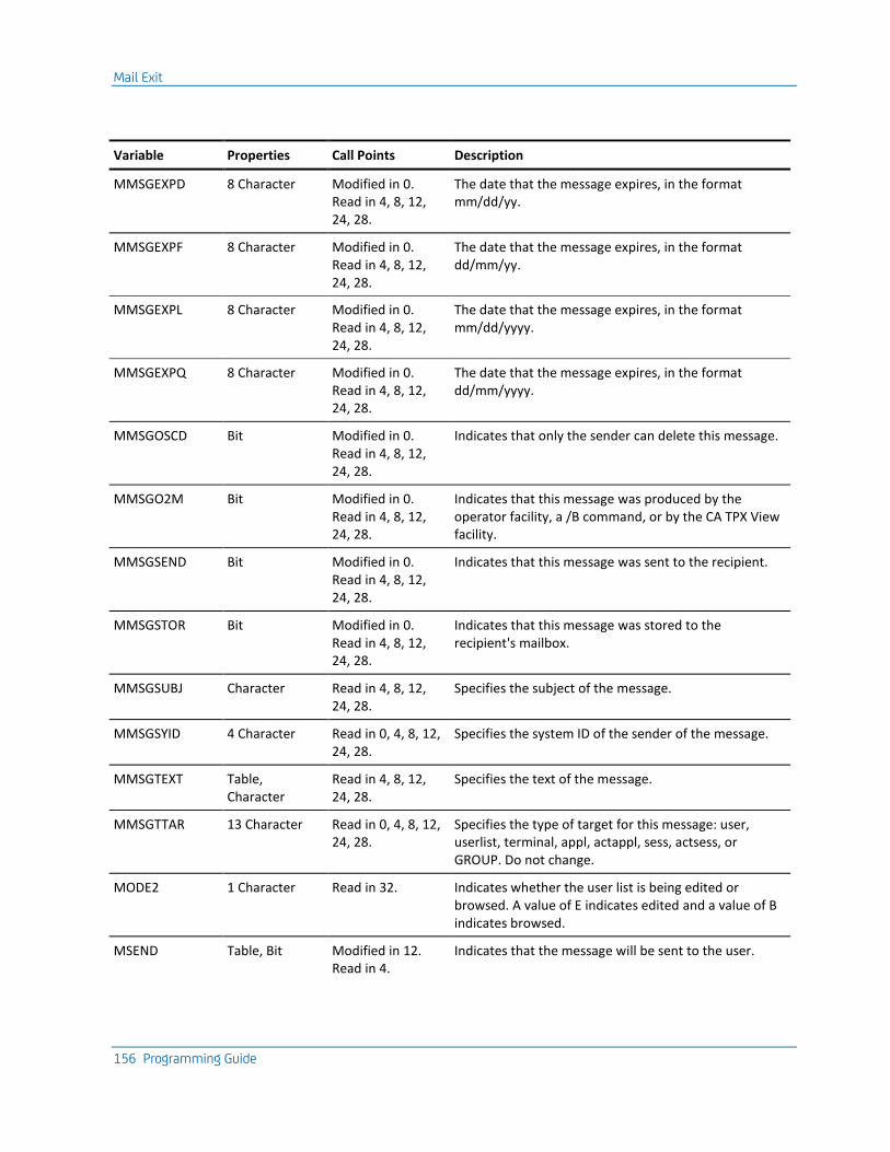
Mail Exit
156 Programming Guide
Variable Properties Call Points Description
MMSGEXPD 8 Character Modified in 0. Read in 4, 8, 12, 24, 28.
The date that the message expires, in the format mm/dd/yy.
MMSGEXPF 8 Character Modified in 0. Read in 4, 8, 12, 24, 28.
The date that the message expires, in the format dd/mm/yy.
MMSGEXPL 8 Character Modified in 0. Read in 4, 8, 12, 24, 28.
The date that the message expires, in the format mm/dd/yyyy.
MMSGEXPQ 8 Character Modified in 0. Read in 4, 8, 12, 24, 28.
The date that the message expires, in the format dd/mm/yyyy.
MMSGOSCD Bit Modified in 0. Read in 4, 8, 12, 24, 28.
Indicates that only the sender can delete this message.
MMSGO2M Bit Modified in 0. Read in 4, 8, 12, 24, 28.
Indicates that this message was produced by the operator facility, a /B command, or by the CA TPX View facility.
MMSGSEND Bit Modified in 0. Read in 4, 8, 12, 24, 28.
Indicates that this message was sent to the recipient.
MMSGSTOR Bit Modified in 0. Read in 4, 8, 12, 24, 28.
Indicates that this message was stored to the recipient's mailbox.
MMSGSUBJ Character Read in 4, 8, 12, 24, 28.
Specifies the subject of the message.
MMSGSYID 4 Character Read in 0, 4, 8, 12, 24, 28.
Specifies the system ID of the sender of the message.
MMSGTEXT Table, Character
Read in 4, 8, 12, 24, 28.
Specifies the text of the message.
MMSGTTAR 13 Character Read in 0, 4, 8, 12, 24, 28.
Specifies the type of target for this message: user, userlist, terminal, appl, actappl, sess, actsess, or GROUP. Do not change.
MODE2 1 Character Read in 32. Indicates whether the user list is being edited or browsed. A value of E indicates edited and a value of B indicates browsed.
MSEND Table, Bit Modified in 12. Read in 4.
Indicates that the message will be sent to the user.
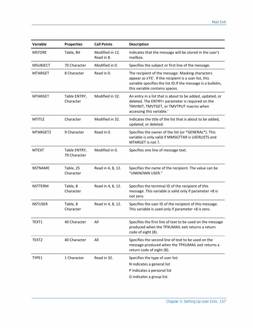
Mail Exit
Chapter 5: Setting Up User Exits 157
Variable Properties Call Points Description
MSTORE Table, Bit Modified in 12. Read in 8.
Indicates that the message will be stored in the user's mailbox.
MSUBJECT 70 Character Modified in 0. Specifies the subject or first line of the message.
MTARGET 8 Character Read in 0. The recipient of the message. Masking characters appear as x'FE'. If the recipient is a user list, this variable specifies the list ID.If the message is a bulletin, this variable contains spaces.
MTARGET Table ENTRY, Character
Modified in 32. An entry in a list that is about to be added, updated, or deleted. The ENTRY= parameter is required on the TMVINIT, TMVTGET, or TMVTPUT macros when accessing this variable.'
MTITLE Character Modified in 32. Indicates the title of the list that is about to be added, updated, or deleted.
MTARGET2 9 Character Read in 0. Specifies the owner of the list (or *GENERAL*). This variable is only valid if MMSGTTAR is USERLISTS and MTARGET is not ?.
MTEXT Table ENTRY, 79 Character
Modified in 0. Specifies one line of message text.
NSTNAME Table, 25 Character
Read in 4, 8, 12. Specifies the name of the recipient. The value can be "UNKNOWN USER."
NSTTERM Table, 8 Character
Read in 4, 8, 12. Specifies the terminal ID of the recipient of this message. This variable is valid only if parameter +8 is not zero.
NSTUSER Table, 8 Character
Read in 4, 8, 12. Specifies the user ID of the recipient of this message. This variable is used only if parameter +8 is zero.
TEXT1 40 Character All Specifies the first line of text to be used on the message produced when the TPXUMAIL exit returns a return code of eight (8).
TEXT2 40 Character All Specifies the second line of text to be used on the message produced when the TPXUMAIL exit returns a return code of eight (8).
TYPE1 1 Character Read in 32. Specifies the type of user list:
N indicates a general list
P indicates a personal list
G indicates a group list.
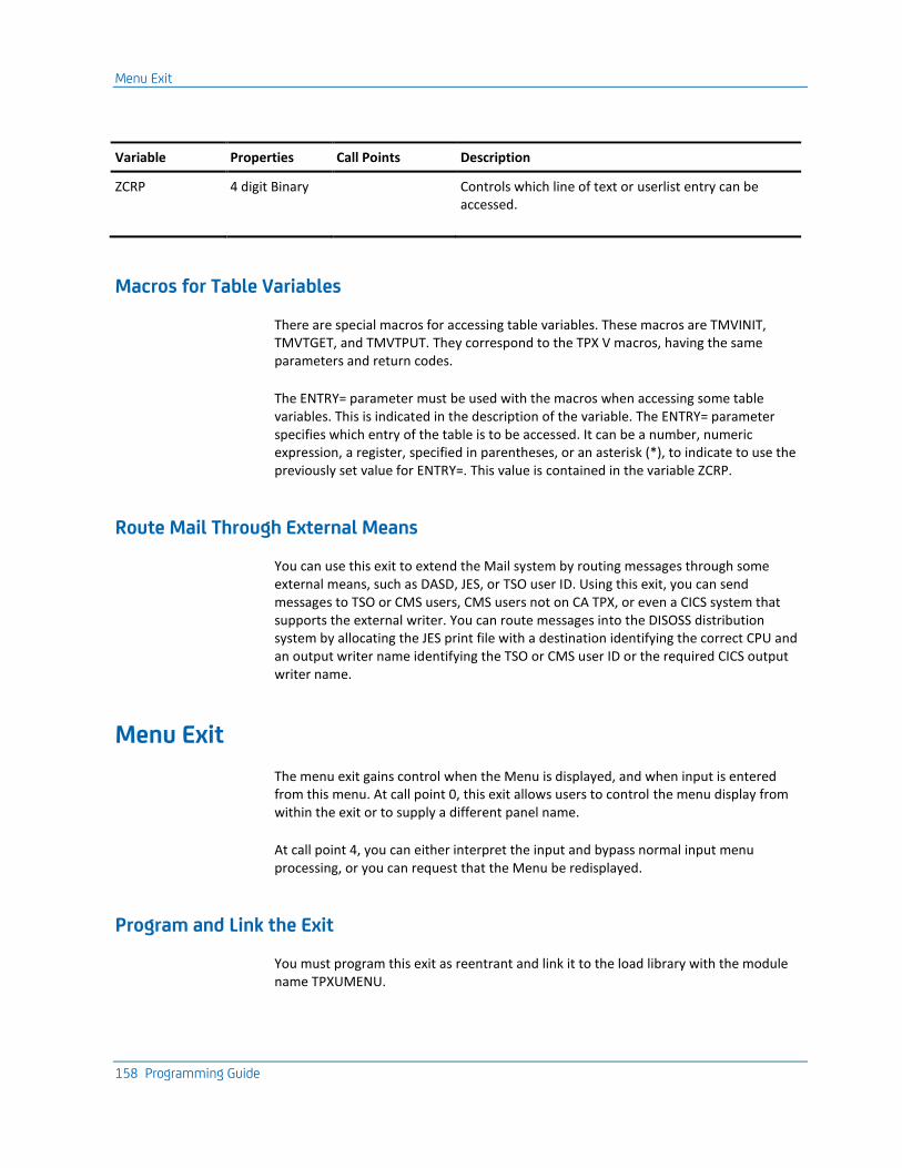
Menu Exit
158 Programming Guide
Variable Properties Call Points Description
ZCRP 4 digit Binary Controls which line of text or userlist entry can be accessed.
Macros for Table Variables
There are special macros for accessing table variables. These macros are TMVINIT, TMVTGET, and TMVTPUT. They correspond to the TPX V macros, having the same parameters and return codes.
The ENTRY= parameter must be used with the macros when accessing some table variables. This is indicated in the description of the variable. The ENTRY= parameter specifies which entry of the table is to be accessed. It can be a number, numeric expression, a register, specified in parentheses, or an asterisk (*), to indicate to use the previously set value for ENTRY=. This value is contained in the variable ZCRP.
Route Mail Through External Means
You can use this exit to extend the Mail system by routing messages through some external means, such as DASD, JES, or TSO user ID. Using this exit, you can send messages to TSO or CMS users, CMS users not on CA TPX, or even a CICS system that supports the external writer. You can route messages into the DISOSS distribution system by allocating the JES print file with a destination identifying the correct CPU and an output writer name identifying the TSO or CMS user ID or the required CICS output writer name.
Menu Exit
The menu exit gains control when the Menu is displayed, and when input is entered from this menu. At call point 0, this exit allows users to control the menu display from within the exit or to supply a different panel name.
At call point 4, you can either interpret the input and bypass normal input menu processing, or you can request that the Menu be redisplayed.
Program and Link the Exit
You must program this exit as reentrant and link it to the load library with the module name TPXUMENU.
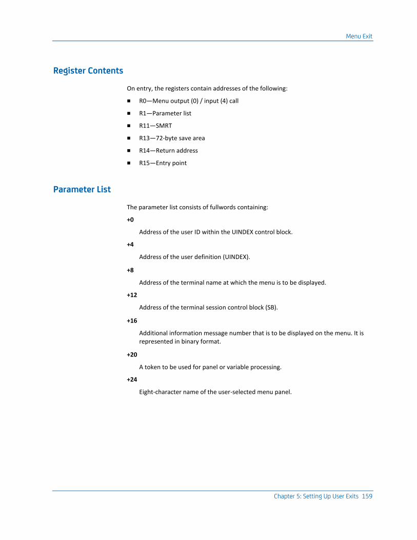
Menu Exit
Chapter 5: Setting Up User Exits 159
Register Contents
On entry, the registers contain addresses of the following:
■ R0—Menu output (0) / input (4) call
■ R1—Parameter list
■ R11—SMRT
■ R13—72-byte save area
■ R14—Return address
■ R15—Entry point
Parameter List
The parameter list consists of fullwords containing:
+0
Address of the user ID within the UINDEX control block.
+4
Address of the user definition (UINDEX).
+8
Address of the terminal name at which the menu is to be displayed.
+12
Address of the terminal session control block (SB).
+16
Additional information message number that is to be displayed on the menu. It is represented in binary format.
+20
A token to be used for panel or variable processing.
+24
Eight-character name of the user-selected menu panel.
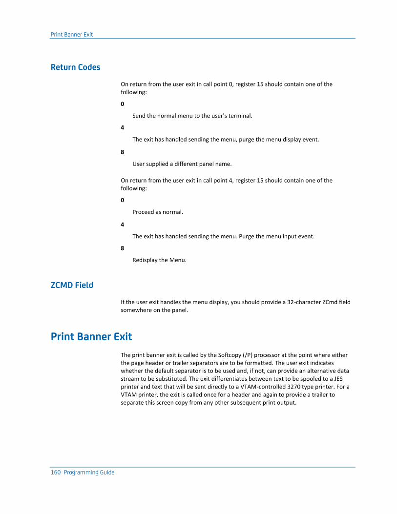
Print Banner Exit
160 Programming Guide
Return Codes
On return from the user exit in call point 0, register 15 should contain one of the following:
0
Send the normal menu to the user's terminal.
4
The exit has handled sending the menu, purge the menu display event.
8
User supplied a different panel name.
On return from the user exit in call point 4, register 15 should contain one of the following:
0
Proceed as normal.
4
The exit has handled sending the menu. Purge the menu input event.
8
Redisplay the Menu.
ZCMD Field
If the user exit handles the menu display, you should provide a 32-character ZCmd field somewhere on the panel.
Print Banner Exit
The print banner exit is called by the Softcopy (/P) processor at the point where either the page header or trailer separators are to be formatted. The user exit indicates whether the default separator is to be used and, if not, can provide an alternative data stream to be substituted. The exit differentiates between text to be spooled to a JES printer and text that will be sent directly to a VTAM-controlled 3270 type printer. For a VTAM printer, the exit is called once for a header and again to provide a trailer to separate this screen copy from any other subsequent print output.

Print Banner Exit
Chapter 5: Setting Up User Exits 161
Program and Link the Exit
You must program the print banner exit as reentrant and link it to the load library with module name TPXUPBNR.
Register Contents
On entry, the registers contain the following:
■ R0—The Entry Point request code:
■ 0—JES Spool Banner
■ 4—VTAM Printer Heading
■ 8—VTAM Printer Trailer
■ R1—Address of the Parameter List
■ R11—Address of the SMRT
■ R13—Address of 72-byte Save Area
■ R14—Return Address
■ R15—Entry Point
Parameter List
The parameter list has the following format:
+0
Address of the 8-byte requestor's printer ID
+4
Address of the 8-byte requestor's user ID
+8
Address of the Date (YY/MM/DD or MM/DD/YY)
+12
Address of the Time (hh:mm:ss)
+16
Screen width in columns for JES or the VTAM Max RU size for this device.
+20
Reserved for the address of the new banner

Print Banner Exit
162 Programming Guide
+24
Reserved for the length of the new banner
+28
Session ID address
+32
Address of the 8-byte requestor's terminal ID
+36
Value of the LU type for VTAM print destinations.
Return Codes
On exit, the following return codes should be set in R15:
0
Use the default banner.
4
Suppress the banner.
8
Use the banner whose address is supplied at offset +20 in the parameter list, the length of which is provided at offset +24.
Location of Banner in Storage
The banner should be located in storage obtained by using GETSTOR or GETSLOT macros. The SOFTCOPY processor will free the provided storage area.
VTAM Printers
For VTAM printers, the whole banner must fit into a single SNA request unit, the size of the RU is supplied as a parameter for VTAM managed printers at offset +16.
JES Banners
For JES print banners, the line length must be 133 characters, and each line must include an ASA carriage control character.
Printer Selection Exit
Chapter 5: Setting Up User Exits 163
Printer Selection Exit
The printer selection exit is called from two points:
■ Softcopy (/P) processing for printer name validation.
■ PPS printer selection. In this case, it gains control after this product receives a session request for a virtual printer. The exit is called after this product has selected the appropriate physical printer to receive the application print data, but before it actually establishes a VTAM session with the real printer. The exit also is called if the product cannot successfully start a VTAM session with the designated physical printer, allowing the user to designate a valid destination for the print data.
Program and Link the Exit
You must program this exit as reentrant and link it into the load library with module name TPXUPSEL.
Register Contents
On entry, the registers contain the address of the following:
■ R0—Call point indicator:
■ For /P call point, R0 = 4
■ For PPS call point, R0 ¹ 4
■ R1—Parameter list
■ R11—SMRT address
■ R13—72-byte save area
■ R14—Return address
■ R15—Entry point
Parameter List for the PPS Call Point
The parameter list consists of four fullwords containing:
+0
Address of selected printer destination name
+4
Address of name of application requesting the session
Query Response Exit
164 Programming Guide
+8
Name of user-supplied destination name
+16
Address of virtual printer name selected
Return Codes for the PPS Call Point
On return from the user exit, register 15 should contain:
0
The selected name is correct. (Print proceeds.)
4
User-supplied name is different from the destination name.
8
The passthrough print request is rejected or the selected printer is invalid.
Parameter List for the /P Call Point
The parameter list consists of one fullword containing:
+0
Address of selected printer destination name.
Return Codes for the /P Call Point
On return from the user exit, register 15 should contain:
0
The selected name is correct. (Print proceeds.)
8
The selected name is invalid. (Print request is rejected.)
Query Response Exit
The query response exit gains control during the logon process immediately after this product issues the read-partition-query command to determine the physical terminal characteristics. The user exit can determine, based upon the query response or other information, whether to instruct this product to rebind with the terminal using a different logmode entry than the one that would normally be used.
Query Response Exit
Chapter 5: Setting Up User Exits 165
Program and Link the Exit
You must program the query response exit as reentrant and link it into the load library with module name TPXUQRSP.
Register Contents
On entry, the registers contain the addresses of the following:
■ R1—Parameter list
■ R11—SMRT
■ R13—72-byte save area
■ R14—Return address
■ R15—Entry point
Parameter List
The parameter list consists of seven fullwords containing:
+0
Address of the 8-byte terminal ID
+4
Address of the query reply inbound structured field
+8
Length of the query reply
+12
Address of the bind image
+16
Length of the bind image
+20
Address of the logmode entry name
+24
Address of the 32 bytes of user data from logon
Queue Exit
166 Programming Guide
Return Codes
On return from the user exit, register 15 should contain either:
0
Continue logon.
4
Rebind with new logmode entry.
For return code 4, the exit should replace the logmode entry name pointed to at offset +20 with the desired entry name.
Queue Exit
The queue exit receives control when the end user issues a /Q or /P command at the terminal. This exit permits the user to authenticate all requests.
Program and Link the Exit
You must program the queue exit as reentrant and link it into the loadlibrarywith module name TPXUQUEU.
Register Contents
On entry, the registers contain the addresses of the following:
■ R1—Parameter list
■ R11—SMRT
■ R13—72-byte save area
■ R14—Return address
■ R15—Entry point
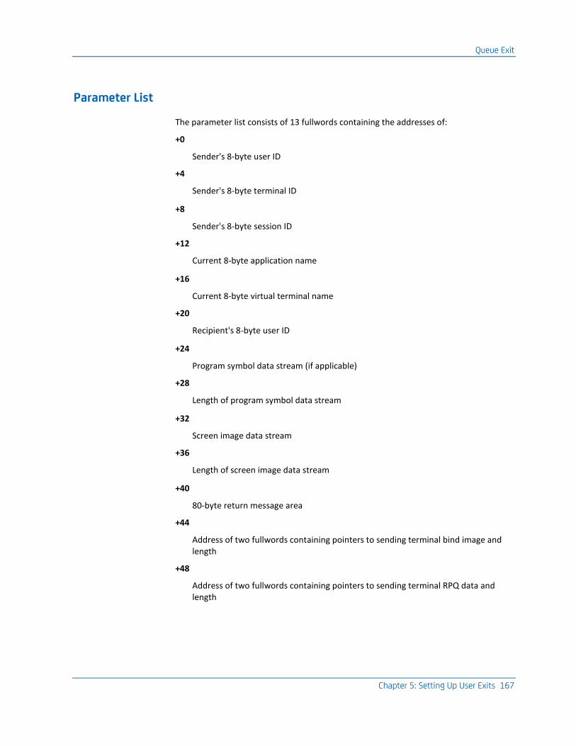
Queue Exit
Chapter 5: Setting Up User Exits 167
Parameter List
The parameter list consists of 13 fullwords containing the addresses of:
+0
Sender's 8-byte user ID
+4
Sender's 8-byte terminal ID
+8
Sender's 8-byte session ID
+12
Current 8-byte application name
+16
Current 8-byte virtual terminal name
+20
Recipient's 8-byte user ID
+24
Program symbol data stream (if applicable)
+28
Length of program symbol data stream
+32
Screen image data stream
+36
Length of screen image data stream
+40
80-byte return message area
+44
Address of two fullwords containing pointers to sending terminal bind image and length
+48
Address of two fullwords containing pointers to sending terminal RPQ data and length

Receive Exit
168 Programming Guide
Return Codes
On return from the user exit, register 15 should contain:
0
Continue with normal processing.
4
User exit has handled; no message needed.
8
User exit has handled; send message.
For return code 8, the 80-byte return message can be used to return two 40-character message lines. These two messages can be placed in the area to which the entry parameter list points. They will be displayed at the requester's terminal.
Route Screen Images
You can use the queue exit to route screen images from CA TPX to some other medium, disk or a JES queue (z/OS only). You can also use this exit to route data to a TSO or CMS user ID. To route a screen image to one of these destinations, allocate the JES print file (z/OS only) with a destination identifying the correct CPU and an output writer name identifying the TSO or CMS user ID.
Session Parameters
The session parameters to which Parameter List +X'44' point are those returned by a VTAM INQUIRE SESSPARMS request. For a description of the format of these parameters, see the IBM VTAM Programming guide. The format of these parameters is mapped by macro ISTDBIND.
Important! In developing code to use this exit, you must remember that after closing a QSAM DCB, the buffer pool is not released and will be reused only if the same copy of the DCB with the buffer pool pointers unchanged is reopened. Continuously reusing a fresh copy of the DCB without issuing FREEPOOL against the previously closed DCBs will inevitably lead to subsequent GETMAIN errors. Similarly, if a DCB is to be reused with different attributes, a FREEPOOL is recommended.
Receive Exit
This exit is called when CA TPX receives data from the terminal. The receive exit gains control immediately after VTAM copies data into the buffers. You can use the receive exit to alter the contents of the input data stream but not to alter the length of the data.
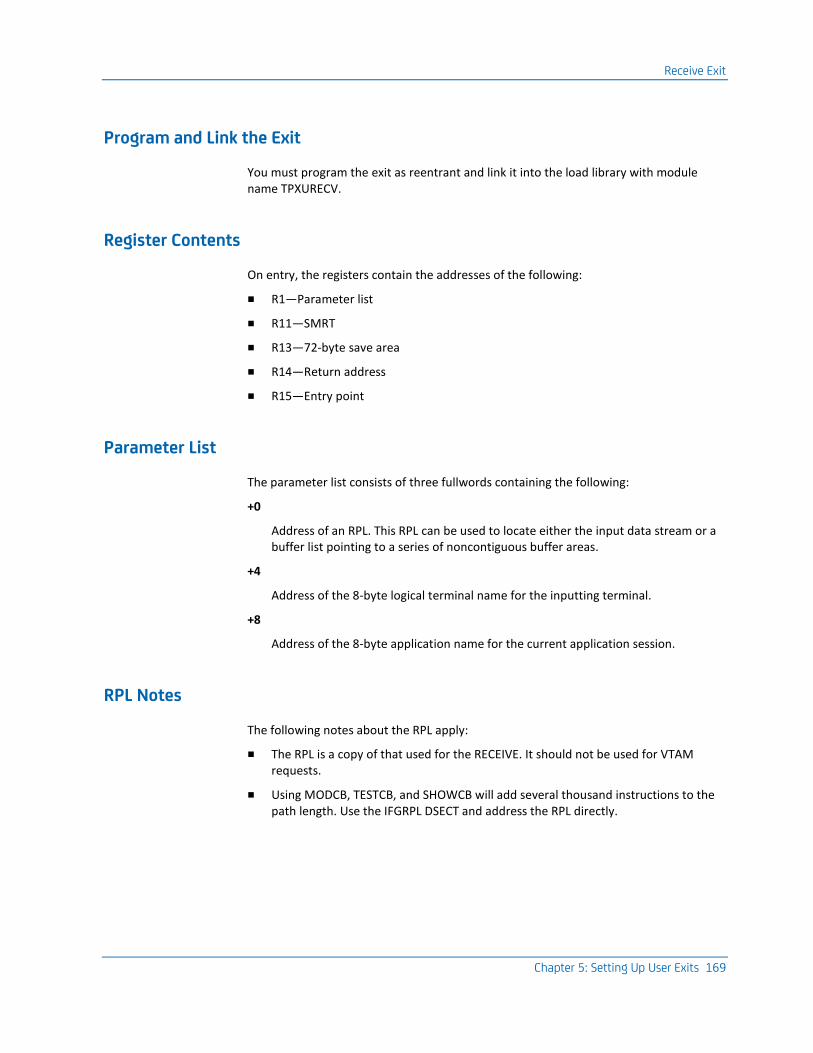
Receive Exit
Chapter 5: Setting Up User Exits 169
Program and Link the Exit
You must program the exit as reentrant and link it into the load library with module name TPXURECV.
Register Contents
On entry, the registers contain the addresses of the following:
■ R1—Parameter list
■ R11—SMRT
■ R13—72-byte save area
■ R14—Return address
■ R15—Entry point
Parameter List
The parameter list consists of three fullwords containing the following:
+0
Address of an RPL. This RPL can be used to locate either the input data stream or a buffer list pointing to a series of noncontiguous buffer areas.
+4
Address of the 8-byte logical terminal name for the inputting terminal.
+8
Address of the 8-byte application name for the current application session.
RPL Notes
The following notes about the RPL apply:
■ The RPL is a copy of that used for the RECEIVE. It should not be used for VTAM requests.
■ Using MODCB, TESTCB, and SHOWCB will add several thousand instructions to the path length. Use the IFGRPL DSECT and address the RPL directly.
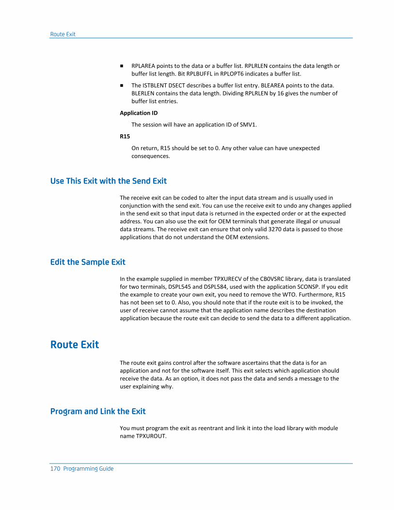
Route Exit
170 Programming Guide
■ RPLAREA points to the data or a buffer list. RPLRLEN contains the data length or buffer list length. Bit RPLBUFFL in RPLOPT6 indicates a buffer list.
■ The ISTBLENT DSECT describes a buffer list entry. BLEAREA points to the data. BLERLEN contains the data length. Dividing RPLRLEN by 16 gives the number of buffer list entries.
Application ID
The session will have an application ID of SMV1.
R15
On return, R15 should be set to 0. Any other value can have unexpected consequences.
Use This Exit with the Send Exit
The receive exit can be coded to alter the input data stream and is usually used in conjunction with the send exit. You can use the receive exit to undo any changes applied in the send exit so that input data is returned in the expected order or at the expected address. You can also use the exit for OEM terminals that generate illegal or unusual data streams. The receive exit can ensure that only valid 3270 data is passed to those applications that do not understand the OEM extensions.
Edit the Sample Exit
In the example supplied in member TPXURECV of the CB0VSRC library, data is translated for two terminals, DSPL545 and DSPL584, used with the application SCONSP. If you edit the example to create your own exit, you need to remove the WTO. Furthermore, R15 has not been set to 0. Also, you should note that if the route exit is to be invoked, the user of receive cannot assume that the application name describes the destination application because the route exit can decide to send the data to a different application.
Route Exit
The route exit gains control after the software ascertains that the data is for an application and not for the software itself. This exit selects which application should receive the data. As an option, it does not pass the data and sends a message to the user explaining why.
Program and Link the Exit
You must program the exit as reentrant and link it into the load library with module name TPXUROUT.
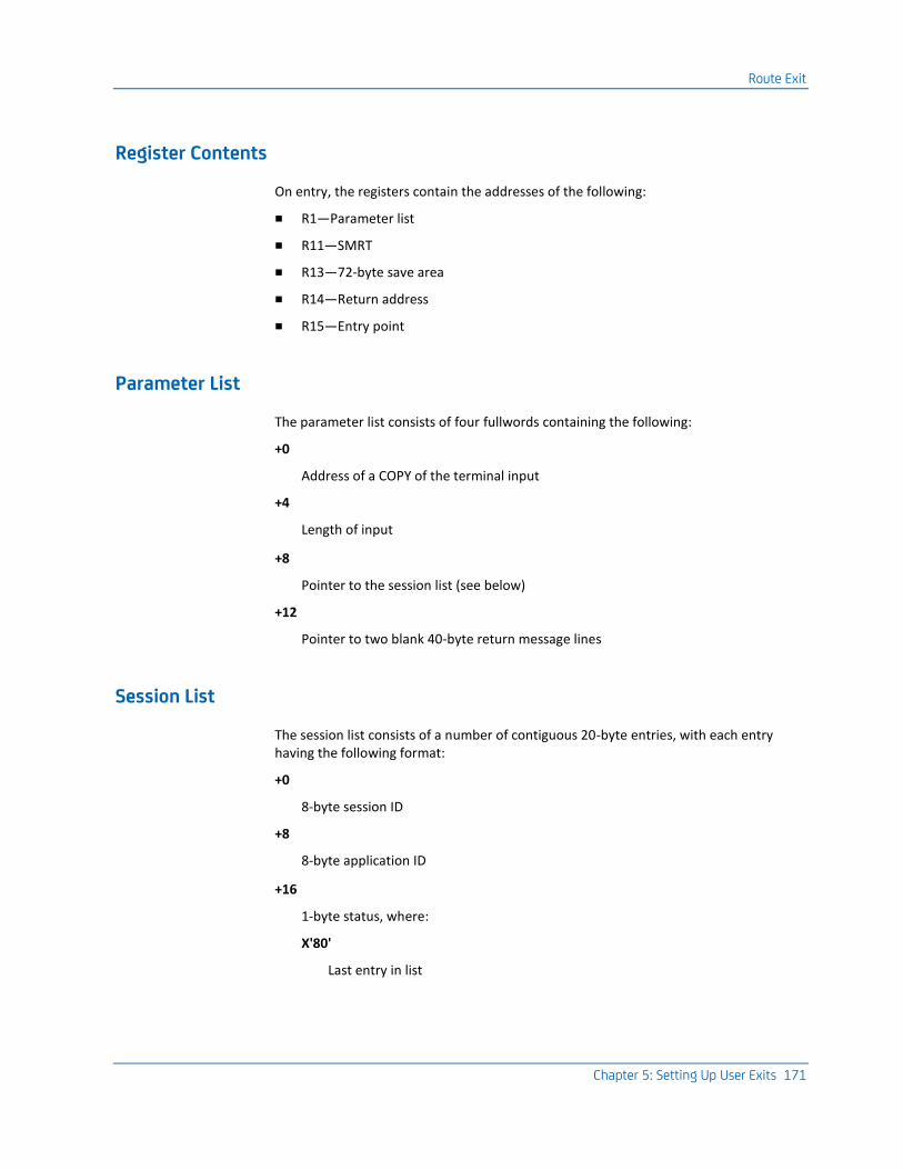
Route Exit
Chapter 5: Setting Up User Exits 171
Register Contents
On entry, the registers contain the addresses of the following:
■ R1—Parameter list
■ R11—SMRT
■ R13—72-byte save area
■ R14—Return address
■ R15—Entry point
Parameter List
The parameter list consists of four fullwords containing the following:
+0
Address of a COPY of the terminal input
+4
Length of input
+8
Pointer to the session list (see below)
+12
Pointer to two blank 40-byte return message lines
Session List
The session list consists of a number of contiguous 20-byte entries, with each entry having the following format:
+0
8-byte session ID
+8
8-byte application ID
+16
1-byte status, where:
X'80'
Last entry in list
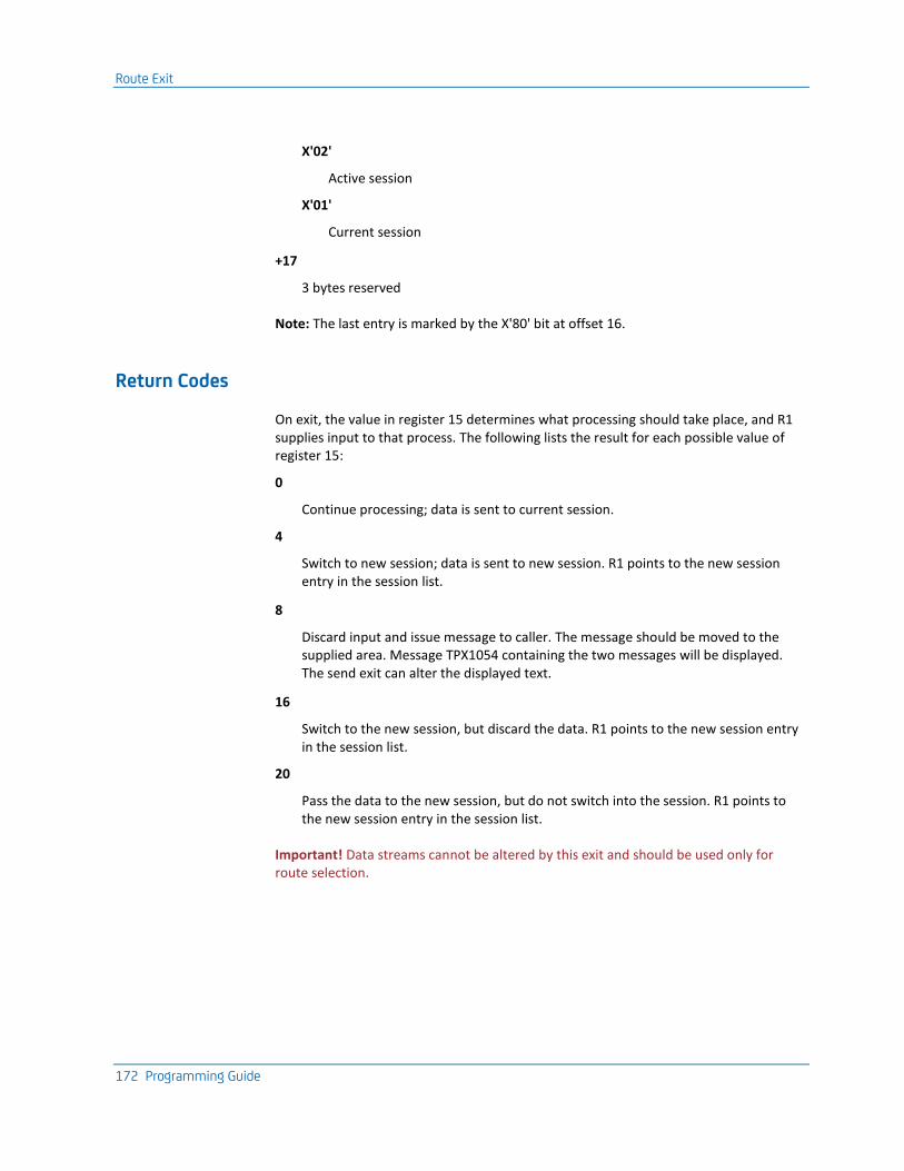
Route Exit
172 Programming Guide
X'02'
Active session
X'01'
Current session
+17
3 bytes reserved
Note: The last entry is marked by the X'80' bit at offset 16.
Return Codes
On exit, the value in register 15 determines what processing should take place, and R1 supplies input to that process. The following lists the result for each possible value of register 15:
0
Continue processing; data is sent to current session.
4
Switch to new session; data is sent to new session. R1 points to the new session entry in the session list.
8
Discard input and issue message to caller. The message should be moved to the supplied area. Message TPX1054 containing the two messages will be displayed. The send exit can alter the displayed text.
16
Switch to the new session, but discard the data. R1 points to the new session entry in the session list.
20
Pass the data to the new session, but do not switch into the session. R1 points to the new session entry in the session list.
Important! Data streams cannot be altered by this exit and should be used only for route selection.
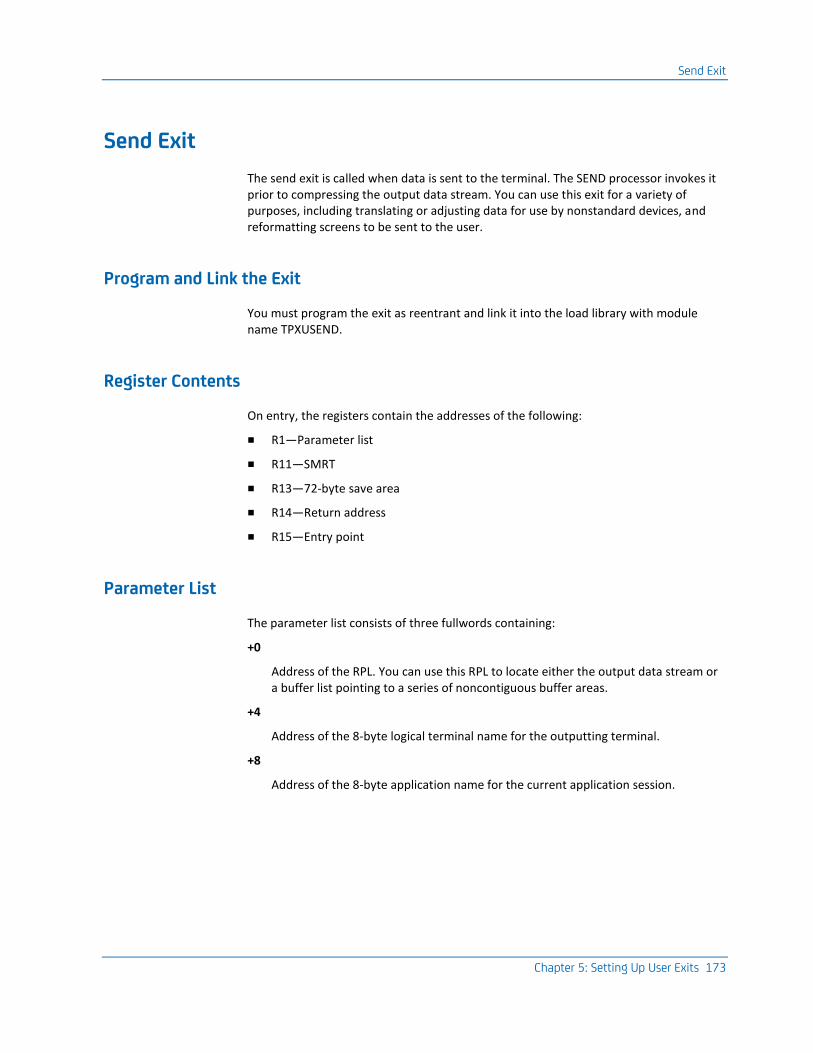
Send Exit
Chapter 5: Setting Up User Exits 173
Send Exit
The send exit is called when data is sent to the terminal. The SEND processor invokes it prior to compressing the output data stream. You can use this exit for a variety of purposes, including translating or adjusting data for use by nonstandard devices, and reformatting screens to be sent to the user.
Program and Link the Exit
You must program the exit as reentrant and link it into the load library with module name TPXUSEND.
Register Contents
On entry, the registers contain the addresses of the following:
■ R1—Parameter list
■ R11—SMRT
■ R13—72-byte save area
■ R14—Return address
■ R15—Entry point
Parameter List
The parameter list consists of three fullwords containing:
+0
Address of the RPL. You can use this RPL to locate either the output data stream or a buffer list pointing to a series of noncontiguous buffer areas.
+4
Address of the 8-byte logical terminal name for the outputting terminal.
+8
Address of the 8-byte application name for the current application session.

Session Initiation/Termination Exit
174 Programming Guide
RPL Notes
The following notes about the RPL apply:
■ The RPL is a copy of that used for the SEND. It should not be used for VTAM requests.
■ Use of MODCB, TESTCB, and SHOWCB will add several thousand instructions to the path length. Use the IFGRPL DSECT and address the RPL directly.
■ RPLAREA points to the data or a buffer list. RPLRLEN contains the data length or buffer list length. Bit RPLBUFFL in RPLOPT6 indicates a buffer list.
■ The ISTBLENT DSECT describes a buffer list entry. BLEAREA points to the data. BLERLEN contains the data length. Dividing RPLRLEN by 16 gives the number of buffer list entries.
Translate or Reformat Output Data
You can use the send exit to translate or reformat output data. As with the receive exit, the send exit cannot alter the length of the data.
Use This Exit with the Receive Exit
This exit is usually used in conjunction with the receive exit. For more information, see Receive Exit.
Session Initiation/Termination Exit
This exit is called at a number of times as shown in the following table:
Call Point Description
0 Before this product issues a request to start an application session
4 When an application session has ended (normally or abnormally)
8 When a terminal session has ended (normally or abnormally).
Program and Link the Exit
You must program the exit as reentrant and link it into the load library with module name TPXUSIST.

Session Initiation/Termination Exit
Chapter 5: Setting Up User Exits 175
Register Contents
On entry, the registers contain the addresses of the following:
■ R0—Call point indicator
■ R1—Parameter list
■ R11—SMRT address
■ R13—72-byte save area
■ R14—Return address
■ R15—Entry point
Parameter Lists
The parameter list for call point zero consists of the following:
+0
Address of an NIB
+4
Address of any session signon data
+8
Length of session signon data
+12
Address of UENTRY that represents this session.
The parameter list for call points 4 and 8 consists of the following:
+0
Address of an NIB
+4
Address of error information if terminal/APPL session ended abnormally
+8
Length of error information in above field
+12
Address of UENTRY that represents this session (for call point 4). Address of UINDEX (for call point 8).
+16
Virtual terminal control block (AMAP) address (only for call point 4).

Signon and Signoff Exit
176 Programming Guide
Return Codes
On exit, register 15 is checked after call point 8. The following lists the results for each possible value of register 15:
0
Normal processing
4
Terminal session is ending, and users would like all of their active application sessions inactivated.
Note: For call point 4, this exit can be used to mark a virtual terminal not available for selection if there is a problem starting a session between this virtual terminal and the application.
After call point 4, the return codes are as follows:
0
Normal processing
4
Session must be restarted.
Signon and Signoff Exit
This exit provides complete flexibility to the authorization and authentication process. It is invoked at a number of points during signon and signoff, as well as being called at Initialization and Termination.
The signon and signoff exit allows the installation to implement one or more of the following:
■ Generic signon
■ Dynamic user definition
■ Dynamic profile definition
■ Multiple authentication mechanisms
■ User-provided authentication
■ System affinity management

Signon and Signoff Exit
Chapter 5: Setting Up User Exits 177
Profiles for Dynamic Users
If you do not use a signon and signoff exit, dynamic users are assigned the default profile specified in the System Options Table (SMRT), unless you are using user level or profile level profile selection with your security system. For more information, see Profile Selection for Dynamic Users in the chapter "Special Features and Customization Tasks."
Program and Link the Exit
You must program the signon and signoff exit as reentrant and link it into the load library with module name TPXUSNSF.
Register Contents
On entry, the registers contain the following:
■ R0—Function code
■ R1—Appropriate parameter list address
■ R11—SMRT address
■ R13—72-byte save area
■ R14—Return address
■ R15—Entry point address
Function Code, Parameters, and Return Codes
The following table lists functions, parameters, return codes, and comments for the signon and signoff exit. The code for each function is shown in parenthesis to the right of the name of the function.
Function Codes Parameters Return Codes Comments
CA TPX startup (0)
Builds user data areas required for subsequent exit requests.
N/A 0 Always This is a general purpose first call exit to permit the user to initialize the security environment. This exit is called from the initialization processes and will be called again if TPXONOFF abnormally terminates as a part of the TPXONOFF re-initialization process (the shutdown exit point is not called in this situation).

Signon and Signoff Exit
178 Programming Guide
Function Codes Parameters Return Codes Comments
Signon data (4)
Inspects and modifies input signon.
See the Parameter List.
0 Always Alter Generic to real name or national character changes. The addresses of parameters 2 and 3 are unpredictable. The SMRTUADS field addresses the first UINDEX entry. UIDXNEXT can be used to chain through the in-storage user entries.
Pre-security (8)
Selects the security system.
See the Parameter List.
0 Continue with signon.
4 Reject the signon with the message supplied.
16 Switch to the system named by the affinity parameter.
The UINDEX block that describes this user can be altered either to inhibit the call to the security package or to select a different package than the one coded in the profile or the system options table (SMRT). UIDXSCTY contains either zero (0) to indicate no security, or the value specified in the user's definition. You can assign one of the following values to this byte to select a different security mechanism:
X'80' CA TPX X'40' RACF X'20' CA ACF2 X'10' User (Code 12) X'08' CA Top Secret X'04' VM Security X'02' SAF (RACF Security Access Facility if implemented) X'01' Not applicable
Equates for these values can be found in the SMRT macro expansion as SEC$TPX, SEC$RACF, and so on.
You can also use this call to cause an Affinity switch to another system before the authentication process is started.
Security (12)
This is an alternative security authentication routine.
See the Parameter List.
0 User ID and Password or password phrase have been accepted.
4 Reject logon with a message to the user.
8 Prompt the user to enter a new password or password phrase.
12 Continue with signon and send the message when signon is complete.
You can use this call to provide your own security algorithm. This call is made if the value of the Security system field in the system options table is USER and no override was found in the user's UINDEX record. The call will also be made if the UINDEX record indicates that a value of USER was set by the pre-security exit or was specified in the Security system field in User Maintenance.

Signon and Signoff Exit
Chapter 5: Setting Up User Exits 179
Function Codes Parameters Return Codes Comments
Post-security
Determines what action to take if the security mechanism rejects the signon request.
See the Parameter List.
0 Continue with the rejection signaled by the security package or by the function.
4 Continue with the rejection, but display your own message.
8 Ignore the rejection and permit normal signon to continue.
12 Ignore the rejection and permit normal signon to continue and send message when signon is complete.
16 Switch to the system named by the affinity parameter
This call is made only if the security mechanism has not authorized the user to use this product and has not reprompted the user. You can take further action to decide whether or not the user is allowed to continue.
The return codes are arranged in an order that ensures that omitting this exit and substituting a dummy exit with all the return codes set to zero will not affect the normal operation of the security mechanism.
If you use this exit to cause an Affinity switch to another system, make sure that an invalid user ID does not cause a loop, being rejected and switched repeatedly.
Get Profile (20)
Requests a model profile.
See the Parameter List.
0 Use the profile name currently in the standard parameter list to build a profile for the user.
4 Reject the signon with the message supplied.
8 Use the default dynamic user profile in the systems options table. 12 The exit has issued ADDPROF statements to build the user, or user-level or profile-level profile selection is being used, as shown in the sample exit TPXUSNSF.
16 Switch to the system named in the affinity parameter.
This call is made if a user entry has been dynamically built. A UINDEX entry is built for all users that are not known to this product if the Dynamic Users Allowed field in the system options table is set to Y. On exit, if return code 0, 8, or 12 is used, the specified profile must already be defined in profile maintenance. This exit could determine that a switch to another system will take place and avoid unnecessarily building a profile for a dynamically added user.
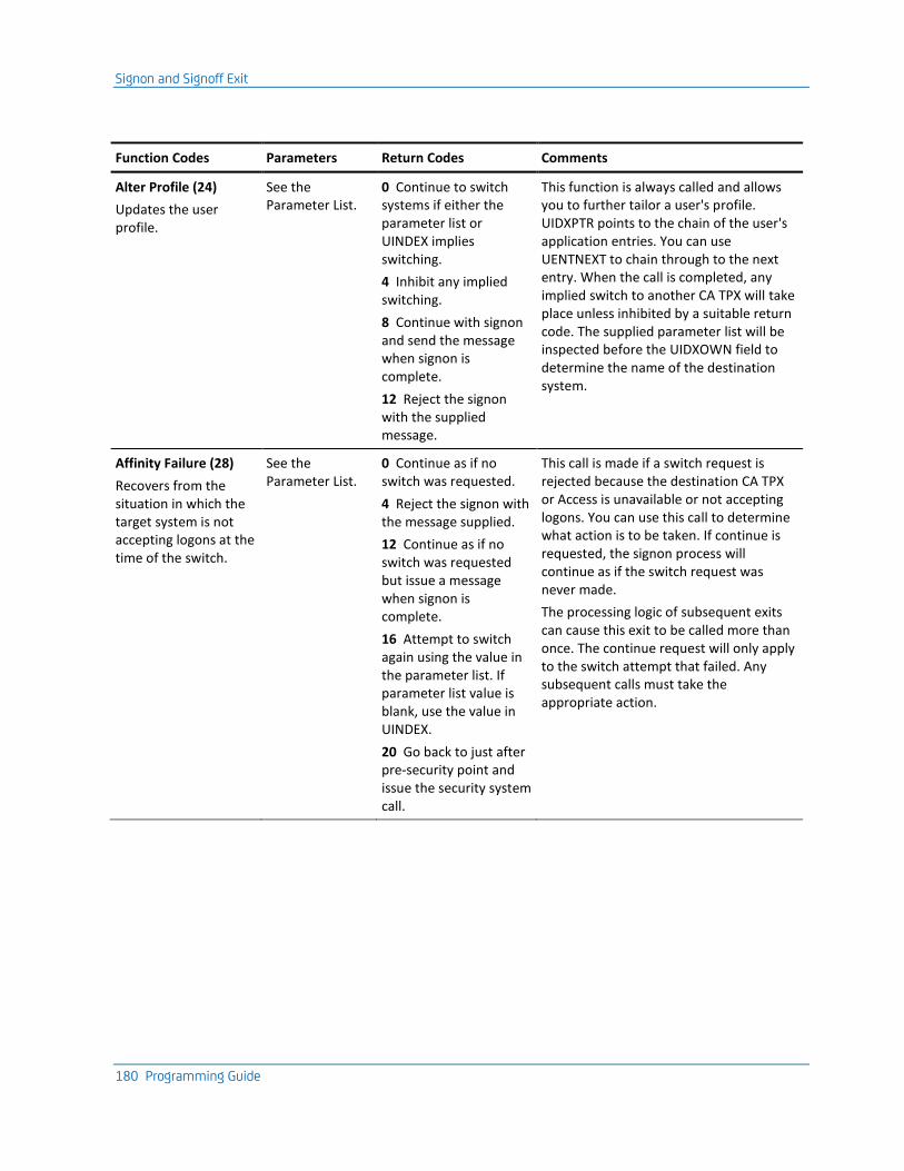
Signon and Signoff Exit
180 Programming Guide
Function Codes Parameters Return Codes Comments
Alter Profile (24)
Updates the user profile.
See the Parameter List.
0 Continue to switch systems if either the parameter list or UINDEX implies switching.
4 Inhibit any implied switching.
8 Continue with signon and send the message when signon is complete.
12 Reject the signon with the supplied message.
This function is always called and allows you to further tailor a user's profile. UIDXPTR points to the chain of the user's application entries. You can use UENTNEXT to chain through to the next entry. When the call is completed, any implied switch to another CA TPX will take place unless inhibited by a suitable return code. The supplied parameter list will be inspected before the UIDXOWN field to determine the name of the destination system.
Affinity Failure (28)
Recovers from the situation in which the target system is not accepting logons at the time of the switch.
See the Parameter List.
0 Continue as if no switch was requested.
4 Reject the signon with the message supplied.
12 Continue as if no switch was requested but issue a message when signon is complete.
16 Attempt to switch again using the value in the parameter list. If parameter list value is blank, use the value in UINDEX.
20 Go back to just after pre-security point and issue the security system call.
This call is made if a switch request is rejected because the destination CA TPX or Access is unavailable or not accepting logons. You can use this call to determine what action is to be taken. If continue is requested, the signon process will continue as if the switch request was never made.
The processing logic of subsequent exits can cause this exit to be called more than once. The continue request will only apply to the switch attempt that failed. Any subsequent calls must take the appropriate action.
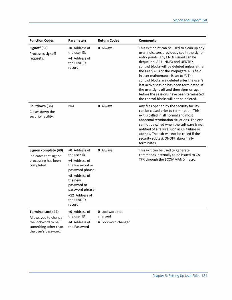
Signon and Signoff Exit
Chapter 5: Setting Up User Exits 181
Function Codes Parameters Return Codes Comments
Signoff (32)
Processes signoff requests.
+0 Address of the user ID.
+4 Address of the UINDEX record.
0 Always This exit point can be used to clean up any user indicators previously set in the signon entry points. Any ENQs issued can be dequeued. All UINDEX and UENTRY control blocks will be deleted unless either the Keep ACB or the Propagate ACB field in user maintenance is set to Y. The control blocks are deleted after the user's last active session has been terminated. If the user signs off and then signs on again before the sessions have been terminated, the control blocks will not be deleted.
Shutdown (36)
Closes down the security facility.
N/A 0 Always Any files opened by the security facility can be closed prior to termination. This exit is called in all normal and most abnormal termination situations. The exit cannot be called when the software is not notified of a failure such as CP failure or abends. The exit will not be called if the security subtask ONOFF abnormally terminates.
Signon complete (40)
Indicates that signon processing has been completed.
+0 Address of the user ID
+4 Address of the Password or password phrase
+8 Address of the new password or password phrase
+12 Address of the UINDEX record
0 Always This exit can be used to generate commands internally to be issued to CA TPX through the $COMMAND macro.
Terminal Lock (44)
Allows you to change the lockword to be something other than the user's password.
+0 Address of the user ID
+4 Address of the Password
0 Lockword not changed
4 Lockword changed
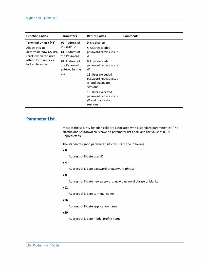
Signon and Signoff Exit
182 Programming Guide
Function Codes Parameters Return Codes Comments
Terminal Unlock (48)
Allows you to determine how CA TPX reacts when the user attempts to unlock a locked terminal.
+0 Address of the user ID
+4 Address of the Password
+8 Address of the Password entered by the user
0 No change
4 User exceeded password retries, issue /F
8 User exceeded password retries, issue /K
12 User exceeded password retries, issue /F and inactivate sessions
16 User exceeded password retries, issue /K and inactivate sessions
Parameter List
Most of the security function calls are associated with a standard parameter list. The startup and shutdown calls have no parameter list at all, and the value of R1 is unpredictable.
The standard signon parameter list consists of the following:
+ 0
Address of 8-byte user ID
+ 4
Address of 8-byte password or password phrase
+ 8
Address of 8-byte new password, new password phrase or blanks
+12
Address of 8-byte terminal name
+16
Address of 8-byte application name
+20
Address of 8-byte model profile name

Signon and Signoff Exit
Chapter 5: Setting Up User Exits 183
+24
Address of 8-byte affinity name
+28
Address of signon 3270 data stream
+32
Length of 3270 data stream
+36
Address of 20-byte user data field
+40
Address of UINDEX record, except for call points 0, 4, and 36
+44
Address of security system control record or 0
+48
Address of the first of four contiguous 80-byte message lines
+52
Address of second 80-byte message line
+56
A token to be used for panel and variable processing
+60
Address of VSAM user record or 0.
General Notes About the Parameter List
The following notes are general information about the parameter list:
1. This parameter list is delivered for function codes 4 through 28, although not every parameter is delivered for every function.
2. The profile name will always be blank. If any of the function calls change the value of this field, the change will be remembered and passed to the get profile call point. If the value is not altered at this time, that model will be used to build the user's profile.
3. The user data field is reserved.
4. The application name is the name of the primary ACB.
5. If Security System=User, the user signon and signoff exit can use the security record address as a suitable pointer to its own security record, but the user must delete the security record before the signon process is completed.
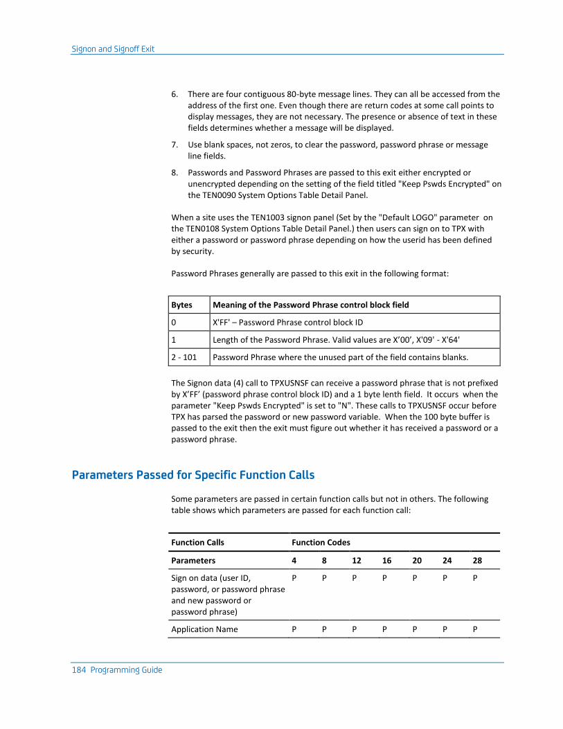
Signon and Signoff Exit
184 Programming Guide
6. There are four contiguous 80-byte message lines. They can all be accessed from the address of the first one. Even though there are return codes at some call points to display messages, they are not necessary. The presence or absence of text in these fields determines whether a message will be displayed.
7. Use blank spaces, not zeros, to clear the password, password phrase or message line fields.
8. Passwords and Password Phrases are passed to this exit either encrypted or unencrypted depending on the setting of the field titled "Keep Pswds Encrypted" on the TEN0090 System Options Table Detail Panel.
When a site uses the TEN1003 signon panel (Set by the "Default LOGO" parameter on the TEN0108 System Options Table Detail Panel.) then users can sign on to TPX with either a password or password phrase depending on how the userid has been defined by security.
Password Phrases generally are passed to this exit in the following format:
Bytes Meaning of the Password Phrase control block field
0 X'FF' – Password Phrase control block ID
1 Length of the Password Phrase. Valid values are X’00’, X'09' - X'64'
2 - 101 Password Phrase where the unused part of the field contains blanks.
The Signon data (4) call to TPXUSNSF can receive a password phrase that is not prefixed by X’FF’ (password phrase control block ID) and a 1 byte lenth field. It occurs when the parameter "Keep Pswds Encrypted" is set to "N". These calls to TPXUSNSF occur before TPX has parsed the password or new password variable. When the 100 byte buffer is passed to the exit then the exit must figure out whether it has received a password or a password phrase.
Parameters Passed for Specific Function Calls
Some parameters are passed in certain function calls but not in others. The following table shows which parameters are passed for each function call:
Function Calls Function Codes
Parameters 4 8 12 16 20 24 28
Sign on data (user ID, password, or password phrase and new password or password phrase)
P P P P P P P
Application Name P P P P P P P
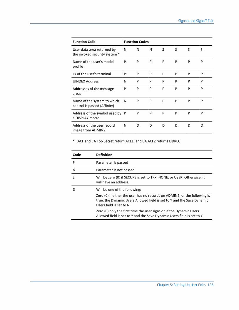
Signon and Signoff Exit
Chapter 5: Setting Up User Exits 185
Function Calls Function Codes
User data area returned by the invoked security system *
N N N S S S S
Name of the user's model profile
P P P P P P P
ID of the user's terminal P P P P P P P
UINDEX Address N P P P P P P
Addresses of the message areas
P P P P P P P
Name of the system to which control is passed (Affinity)
N P P P P P P
Address of the symbol used by a DISPLAY macro
P P P P P P P
Address of the user record image from ADMIN2
N D D D D D D
* RACF and CA Top Secret return ACEE, and CA ACF2 returns LIDREC
Code Definition
P Parameter is passed
N Parameter is not passed
S Will be zero (0) if SECURE is set to TPX, NONE, or USER. Otherwise, it will have an address.
D Will be one of the following:
Zero (0) if either the user has no records on ADMIN2, or the following is true: the Dynamic Users Allowed field is set to Y and the Save Dynamic Users field is set to N.
Zero (0) only the first time the user signs on if the Dynamic Users Allowed field is set to Y and the Save Dynamic Users field is set to Y.
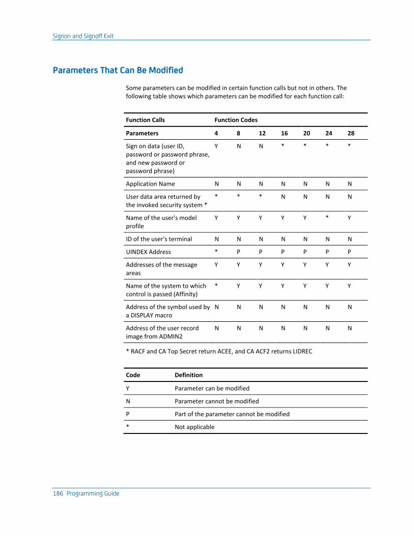
Signon and Signoff Exit
186 Programming Guide
Parameters That Can Be Modified
Some parameters can be modified in certain function calls but not in others. The following table shows which parameters can be modified for each function call:
Function Calls Function Codes
Parameters 4 8 12 16 20 24 28
Sign on data (user ID, password or password phrase, and new password or password phrase)
Y N N * * * *
Application Name N N N N N N N
User data area returned by the invoked security system *
* * * N N N N
Name of the user's model profile
Y Y Y Y Y * Y
ID of the user's terminal N N N N N N N
UINDEX Address * P P P P P P
Addresses of the message areas
Y Y Y Y Y Y Y
Name of the system to which control is passed (Affinity)
* Y Y Y Y Y Y
Address of the symbol used by a DISPLAY macro
N N N N N N N
Address of the user record image from ADMIN2
N N N N N N N
* RACF and CA Top Secret return ACEE, and CA ACF2 returns LIDREC
Code Definition
Y Parameter can be modified
N Parameter cannot be modified
P Part of the parameter cannot be modified
* Not applicable
Signon and Signoff Exit
Chapter 5: Setting Up User Exits 187
Multitasking
All of the signon and signoff exit calls, except for code 40, are made from the CA TPX security subtask ONOFF, so there are no user multitasking considerations. Users can issue ENQ DEQ or I/O macros without worrying about which task is associated with the request.
Signon Function
The signon process is serialized in such a way that after the signon data call point has been entered, the signon function will not be entered for any other user until the request has been completed (function call 24), rejected (function call 16 return code 0), or a new password or password phrase has been requested (function code 12 return code 8 or the appropriate RACF, CA Top Secret, or CA ACF2 return code).
Abend in ONOFF or the User Exit
In the event of an Abend in ONOFF or the user exit, the subtask is not terminated. All acquired storage remains available, but the task is restarted. If the initialization call is driven a second time, the user must either delete and restart or check the validity of the data.
Session Portability
When a user signs on to a terminal while sessions are active at another terminal, care must be taken, especially in the signoff function call. The session is not transferred until the signon process is complete, and the user is not linked to the new terminal until the signoff process has completed.
During signon, you can detect whether a user has active sessions on another terminal by inspecting the value of UINDEX field UIDXTERM. If UIDXTERM is not 0, it is pointing to the Session Block of the terminal currently associated with this user. The terminal LUNAME is located at offset +6 from this address. The signoff function call will occur sometime after the signon call for the new terminal, but other signon or signoff calls for other terminals or users can occur between the last signon call for the new terminal and the signoff call for the old. To help you correlate these calls, CA TPX reserves a field UIDXUSER in the UINDEX for use by the signon exit.
Signon and Signoff Exit
188 Programming Guide
ADDPROF Macro
This macro is used to build user profiles in memory by copying all of the information from the specified profile to the user definition. Multiple ADDPROF macros can be used to build a single user definition. The user-specific information specified in the first profile is used to build the UINDEX control block. For every subsequent ADDPROF issued, only the session records are added or replaced in the user's definition in memory.
If the return code is a number other than zero (0), the profile was not found. Be sure to code the list so that it takes the appropriate action if this occurs.
Notes:
1. This macro should be issued at the Get Profile call point (call point 20) of TPXUSNSF. If the macro is issued at any other call point, the results are unpredictable.
2. This macro will modify the contents of registers 14, 15, 0, and 1.
Format of the ADDPROF Macro
The format of the ADDPROF macro is:
ADDPROF UINDEX=,NAME=,PARMLST=
where:
UINDEX
Contains the address of the UINDEX record
NAME
Contains the address of the profile name
PARMLST
Contains the address of the parameter list that is passed to TPXUSNSF in register 1
Switch-in Exit
Chapter 5: Setting Up User Exits 189
Affinity Processing
At a number of points throughout the signon process, you can request that the signon process be terminated and a switch be made to PASS the terminal to another CA TPX. By default, this decision is made after the alter profile call based on the value found in UIDXOWN. Switch requests made in the TPXUSNSF exit will override the default Affinity setting in the System Options Table (SMRT). The switch requests allow an installation to recognize that a switch will take place and to make the switch event earlier in the signon to avoid unnecessary processing in this system.
After being switched, complete signon processing takes place in the destination system. One reason for providing this flexibility is to allow you to determine heuristically, based on some selection criteria, which system is to support this user. Because this process can set up a never-ending loop of switches, you should include a mechanism to guard against such an occurrence.
The address of the 8-byte C Affinity name is contained in +24 of the parameter list. The user must place the application ID in the specified address. When the call point is entered, this product will have placed blanks in the address.
Switch-in Exit
This exit is used to customize how an application's session is refreshed.
The switch-in exit gains control when CA TPX refreshes a user's session screen image. If the NetSpy interface is active, control is passed after generation of the interface message. The data or sense code sent to the application is not validated by CA TPX. It is a means to instruct the application to refresh the screen image in its entirety, but it can be used for any purpose.
Program and Link the Exit
You must program the switch-in exit as reentrant and link it into the CA TPX load library with module name TPXUSWIN.
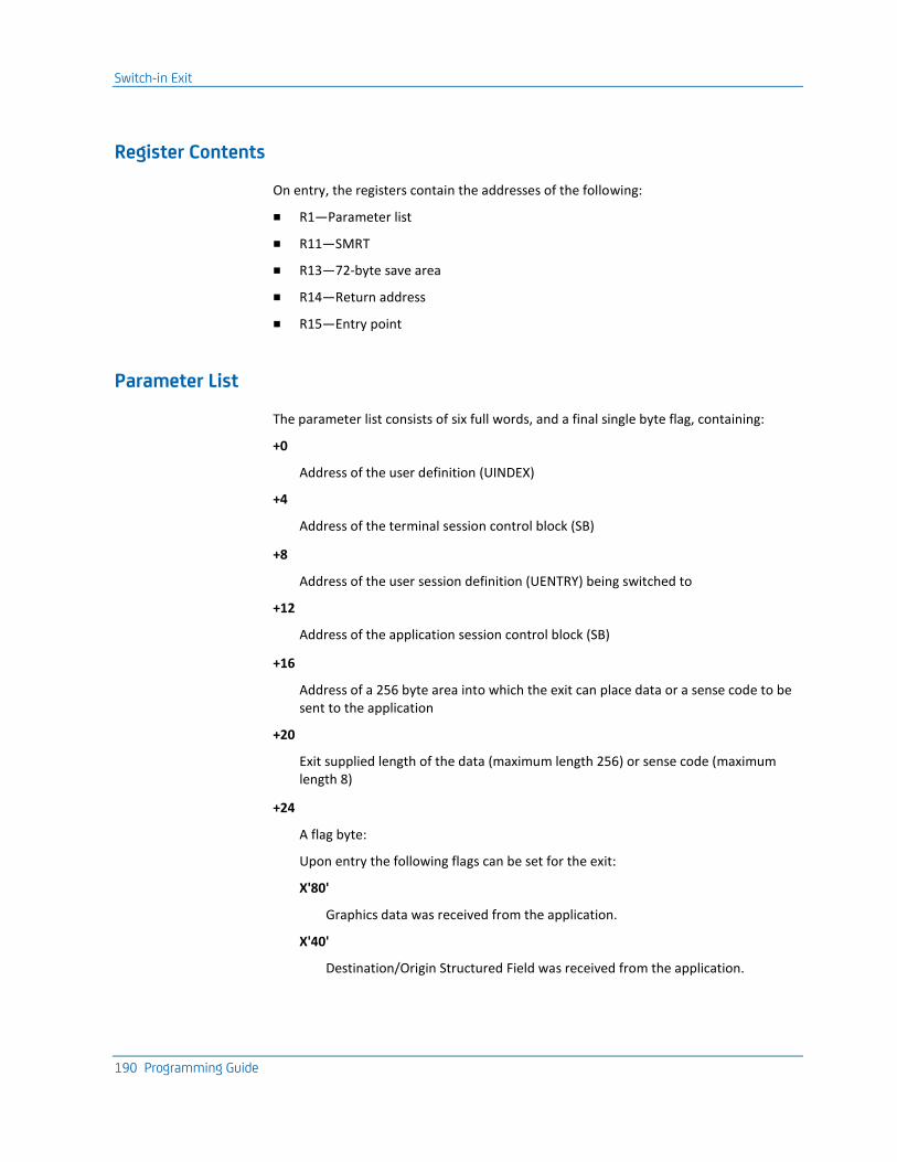
Switch-in Exit
190 Programming Guide
Register Contents
On entry, the registers contain the addresses of the following:
■ R1—Parameter list
■ R11—SMRT
■ R13—72-byte save area
■ R14—Return address
■ R15—Entry point
Parameter List
The parameter list consists of six full words, and a final single byte flag, containing:
+0
Address of the user definition (UINDEX)
+4
Address of the terminal session control block (SB)
+8
Address of the user session definition (UENTRY) being switched to
+12
Address of the application session control block (SB)
+16
Address of a 256 byte area into which the exit can place data or a sense code to be sent to the application
+20
Exit supplied length of the data (maximum length 256) or sense code (maximum length 8)
+24
A flag byte:
Upon entry the following flags can be set for the exit:
X'80'
Graphics data was received from the application.
X'40'
Destination/Origin Structured Field was received from the application.
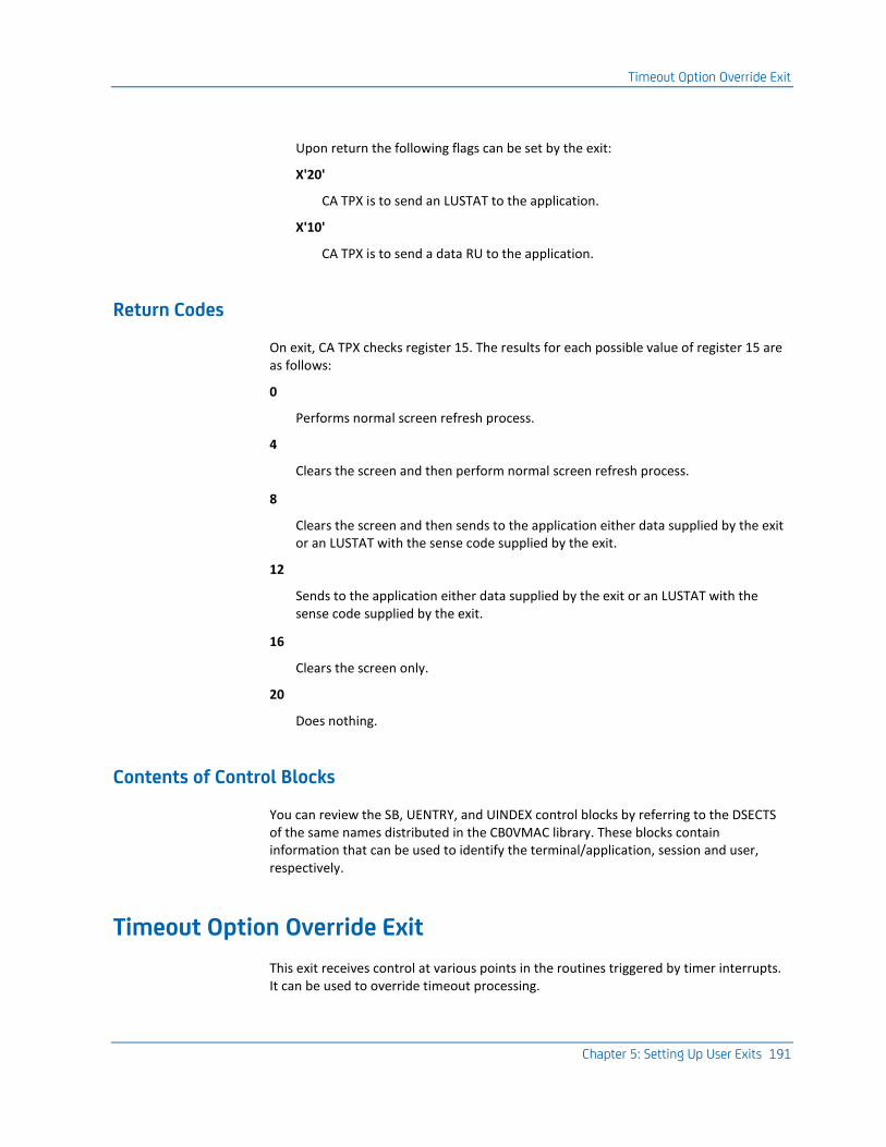
Timeout Option Override Exit
Chapter 5: Setting Up User Exits 191
Upon return the following flags can be set by the exit:
X'20'
CA TPX is to send an LUSTAT to the application.
X'10'
CA TPX is to send a data RU to the application.
Return Codes
On exit, CA TPX checks register 15. The results for each possible value of register 15 are as follows:
0
Performs normal screen refresh process.
4
Clears the screen and then perform normal screen refresh process.
8
Clears the screen and then sends to the application either data supplied by the exit or an LUSTAT with the sense code supplied by the exit.
12
Sends to the application either data supplied by the exit or an LUSTAT with the sense code supplied by the exit.
16
Clears the screen only.
20
Does nothing.
Contents of Control Blocks
You can review the SB, UENTRY, and UINDEX control blocks by referring to the DSECTS of the same names distributed in the CB0VMAC library. These blocks contain information that can be used to identify the terminal/application, session and user, respectively.
Timeout Option Override Exit
This exit receives control at various points in the routines triggered by timer interrupts. It can be used to override timeout processing.

Timeout Option Override Exit
192 Programming Guide
Program and Link the Exit
You must program this exit as reentrant and link it to the library with module name TPXUTOOO.
Register Contents
On entry, the registers contain the addresses of the following:
■ R0—Call type
■ R1—Parameter list
■ R11—SMRT
■ R13—72-byte save area
■ R14—Return address
■ R15—Entry point
Entry Codes
Register 0 has the following entry code:
0
Entered once at startup.
4
Entered after it has been determined that a user application has satisfied its timeout criterion but before any action has been taken.
8
Entered after it has been determined that a user has satisfied its first level timeout criterion but before any action has been taken.
12
Entered after it has been determined that a user previously timed-out to a lock screen has satisfied its second level timeout criterion but before any action has been taken.
16
Entered after it has been determined that a terminal at the logo has satisfied its timeout criterion but before any action has been taken.
20
Entered at the beginning of a timeout processing cycle.

Timeout Option Override Exit
Chapter 5: Setting Up User Exits 193
Parameter List
The parameter list varies by entry code:
0,20—
■ +0— 0
■ +4— 0
■ +8— Address of workarea
4—
■ +0—Address of user ID in the UINDEX
■ +4—Address of session ID in the UENTRY
■ +8—Address of workarea
8,12—
■ +0—Address of UINDEX
■ +4—Address of terminal ID in the terminal session control block (SB)
■ +8—Address of workarea
16—
■ +0—0
■ +4—Address of terminal ID in the terminal session control block (SB)
■ +8—Address of workarea
Workarea Format
The workarea has the following format:
+0—
8-byte time in STCK format. DO NOT ALTER THIS VALUE.
+8—
4-byte word available to the exit
+12—
TIMEOUT option flag byte. This byte contains the defined TIMEOUT action for call type 4 through 16. Alter it if you wish to change the action to be taken.
■ X'01'—Log off terminal
■ X'02'—Sign off user
■ X'04'—Lock terminal
■ X'08'—Inactivate all sessions
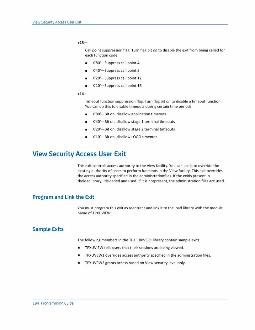
View Security Access User Exit
194 Programming Guide
+13—
Call point suppression flag. Turn flag bit on to disable the exit from being called for each function code.
■ X'80'—Suppress call point 4
■ X'40'—Suppress call point 8
■ X'20'—Suppress call point 12
■ X'10'—Suppress call point 16
+14—
Timeout function suppression flag. Turn flag bit on to disable a timeout function. You can do this to disable timeouts during certain time periods.
■ X'80'—Bit on, disallow application timeouts
■ X'40'—Bit on, disallow stage 1 terminal timeouts
■ X'20'—Bit on, disallow stage 2 terminal timeouts
■ X'10'—Bit on, disallow LOGO timeouts
View Security Access User Exit
This exit controls access authority to the View facility. You can use it to override the existing authority of users to perform functions in the View facility. This exit overrides the access authority specified in the administrationfiles. If the exitis present in theloadlibrary, itisloaded and used. If it is notpresent, the administration files are used.
Program and Link the Exit
You must program this exit as reentrant and link it to the load library with the module name of TPXUVIEW.
Sample Exits
The following members in the TPX.CB0VSRC library contain sample exits:
■ TPXUVIEW tells users that their sessions are being viewed.
■ TPXUVEW1 overrides access authority specified in the administration files.
■ TPXUVEW2 grants access based on View security level only.
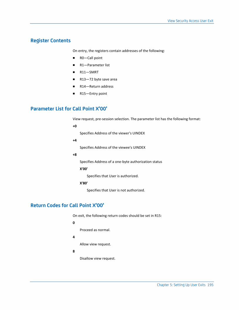
View Security Access User Exit
Chapter 5: Setting Up User Exits 195
Register Contents
On entry, the registers contain addresses of the following:
■ R0—Call point
■ R1—Parameter list
■ R11—SMRT
■ R13—72 byte save area
■ R14—Return address
■ R15—Entry point
Parameter List for Call Point X'00'
View request, pre-session selection. The parameter list has the following format:
+0
Specifies Address of the viewer's UINDEX
+4
Specifies Address of the viewee's UINDEX
+8
Specifies Address of a one-byte authorization status
X'00'
Specifies that User is authorized.
X'80'
Specifies that User is not authorized.
Return Codes for Call Point X'00'
On exit, the following return codes should be set in R15:
0
Proceed as normal.
4
Allow view request.
8
Disallow view request.
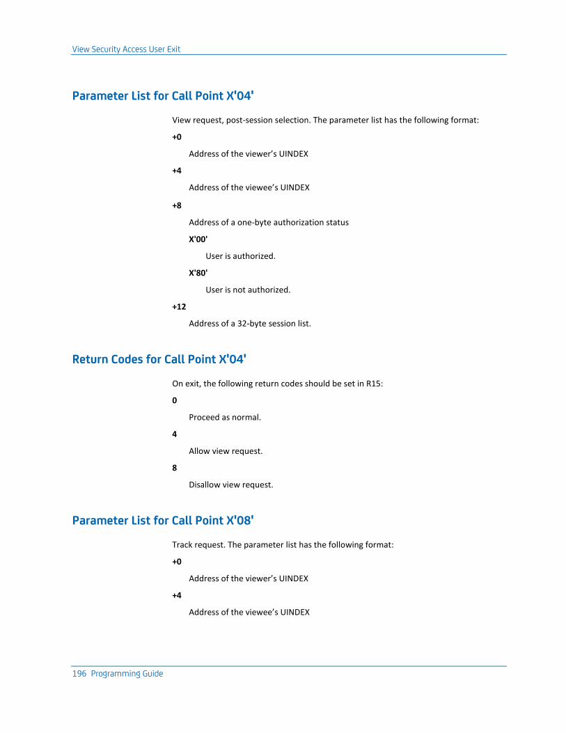
View Security Access User Exit
196 Programming Guide
Parameter List for Call Point X'04'
View request, post-session selection. The parameter list has the following format:
+0
Address of the viewer’s UINDEX
+4
Address of the viewee’s UINDEX
+8
Address of a one-byte authorization status
X'00'
User is authorized.
X'80'
User is not authorized.
+12
Address of a 32-byte session list.
Return Codes for Call Point X'04'
On exit, the following return codes should be set in R15:
0
Proceed as normal.
4
Allow view request.
8
Disallow view request.
Parameter List for Call Point X'08'
Track request. The parameter list has the following format:
+0
Address of the viewer’s UINDEX
+4
Address of the viewee’s UINDEX

View Security Access User Exit
Chapter 5: Setting Up User Exits 197
+8
Address of a one-byte authorization status
X'00'
User is authorized.
X'80'
User is not authorized.
Return Codes for Call Point X'08'
On exit, the following return codes should be set in R15:
0
Proceed as normal.
4
Allow track request.
8
Disallow track request.
Parameters for Call Point X'12'
Data received for a view session. The parameter list has the following format:
+0
Address of the viewer’s UINDEX
+4
Address of the viewee’s UINDEX
+8
Address of a one-byte RU data direction
X'00'
Data RU from application to viewee’s terminal.
X'80'
Data RU from viewee’s terminal to application.
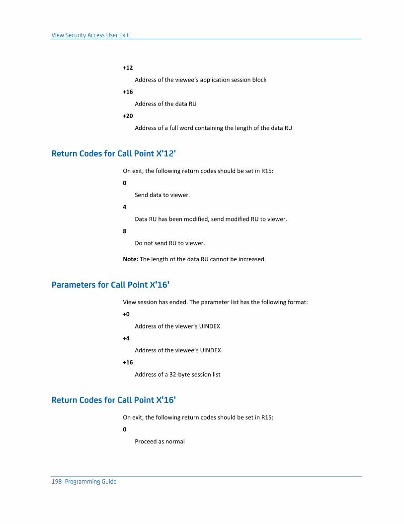
View Security Access User Exit
198 Programming Guide
+12
Address of the viewee’s application session block
+16
Address of the data RU
+20
Address of a full word containing the length of the data RU
Return Codes for Call Point X'12'
On exit, the following return codes should be set in R15:
0
Send data to viewer.
4
Data RU has been modified, send modified RU to viewer.
8
Do not send RU to viewer.
Note: The length of the data RU cannot be increased.
Parameters for Call Point X'16'
View session has ended. The parameter list has the following format:
+0
Address of the viewer’s UINDEX
+4
Address of the viewee’s UINDEX
+16
Address of a 32-byte session list
Return Codes for Call Point X'16'
On exit, the following return codes should be set in R15:
0
Proceed as normal

View Security Access User Exit
Chapter 5: Setting Up User Exits 199
Parameters for Call Point X'20'
Track session has ended. The parameter list has the following format:
+0
Address of the viewer’s UINDEX
+4
Address of the viewee’s UINDEX
Return Codes for Call Point X'20'
On exit, the following return codes should be set in R15:
0
Proceed as normal
Parameters for Call Point X'24'
Conference is initiating. The parameter list has the following format:
+0
Address of the conference initiator's UINDEX.
+4
Address of an 8-byte session ID.
+8
Address of a 1-byte conference type
X'00'
Public conference.
X'04'
Private conference.
+12
Address of the conference participant count (this is the number of entries in the conference participant user ID list). This value is 0 for public conferences.
+16
Address of the conference participant user ID list. This address is 0 for public conferences.
Each entry is 16-bytes. The first 8 bytes contain the user ID and the second 8 bytes contain that user's terminal ID.
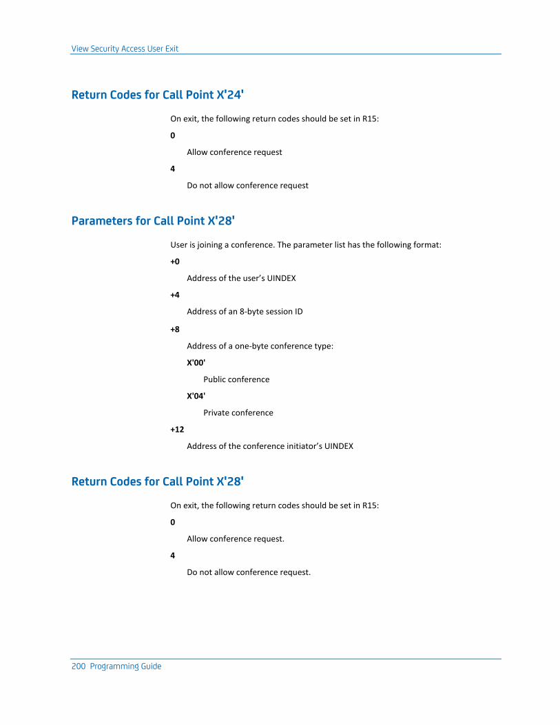
View Security Access User Exit
200 Programming Guide
Return Codes for Call Point X'24'
On exit, the following return codes should be set in R15:
0
Allow conference request
4
Do not allow conference request
Parameters for Call Point X'28'
User is joining a conference. The parameter list has the following format:
+0
Address of the user’s UINDEX
+4
Address of an 8-byte session ID
+8
Address of a one-byte conference type:
X'00'
Public conference
X'04'
Private conference
+12
Address of the conference initiator’s UINDEX
Return Codes for Call Point X'28'
On exit, the following return codes should be set in R15:
0
Allow conference request.
4
Do not allow conference request.
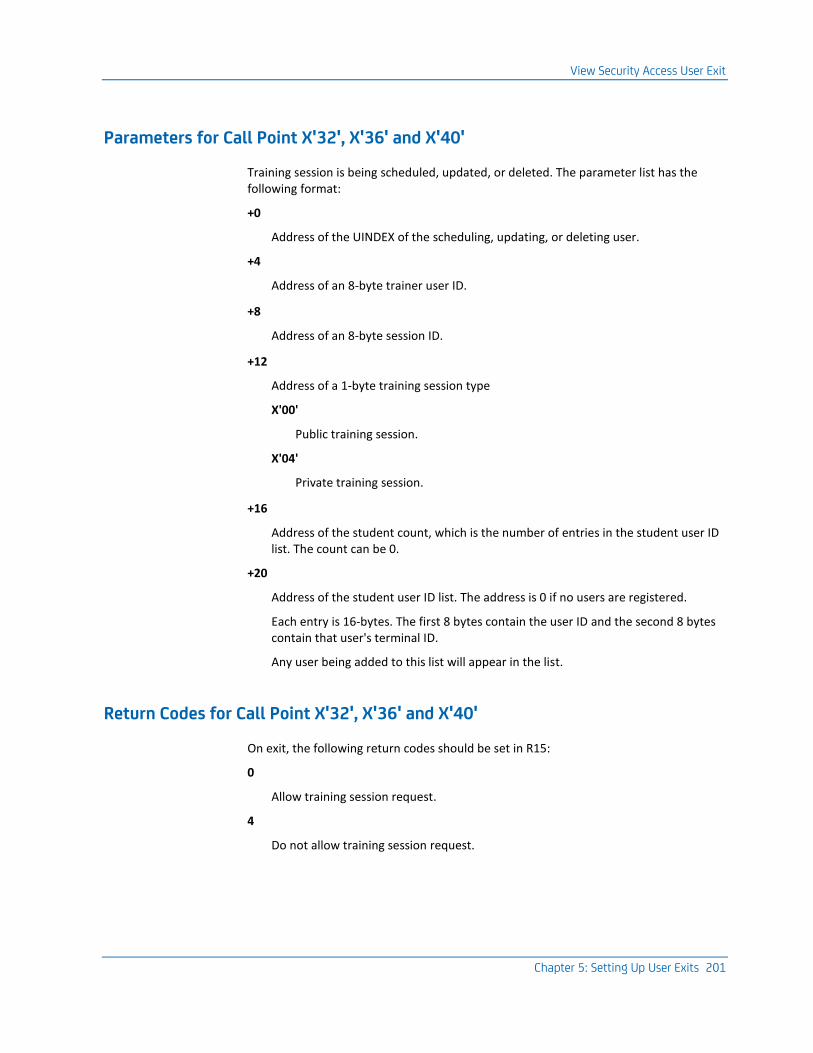
View Security Access User Exit
Chapter 5: Setting Up User Exits 201
Parameters for Call Point X'32', X'36' and X'40'
Training session is being scheduled, updated, or deleted. The parameter list has the following format:
+0
Address of the UINDEX of the scheduling, updating, or deleting user.
+4
Address of an 8-byte trainer user ID.
+8
Address of an 8-byte session ID.
+12
Address of a 1-byte training session type
X'00'
Public training session.
X'04'
Private training session.
+16
Address of the student count, which is the number of entries in the student user ID list. The count can be 0.
+20
Address of the student user ID list. The address is 0 if no users are registered.
Each entry is 16-bytes. The first 8 bytes contain the user ID and the second 8 bytes contain that user's terminal ID.
Any user being added to this list will appear in the list.
Return Codes for Call Point X'32', X'36' and X'40'
On exit, the following return codes should be set in R15:
0
Allow training session request.
4
Do not allow training session request.
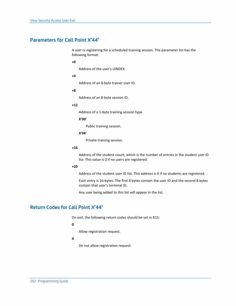
View Security Access User Exit
202 Programming Guide
Parameters for Call Point X'44'
A user is registering for a scheduled training session. The parameter list has the following format:
+0
Address of the user’s UINDEX.
+4
Address of an 8-byte trainer user ID.
+8
Address of an 8-byte session ID.
+12
Address of a 1-byte training session type
X'00'
Public training session.
X'04'
Private training session.
+16
Address of the student count, which is the number of entries in the student user ID list. This value is 0 if no users are registered.
+20
Address of the student user ID list. This address is 0 if no students are registered.
Each entry is 16-bytes. The first 8 bytes contain the user ID and the second 8 bytes contain that user’s terminal ID.
Any user being added to this list will appear in the list.
Return Codes for Call Point X'44'
On exit, the following return codes should be set in R15:
0
Allow registration request.
4
Do not allow registration request.
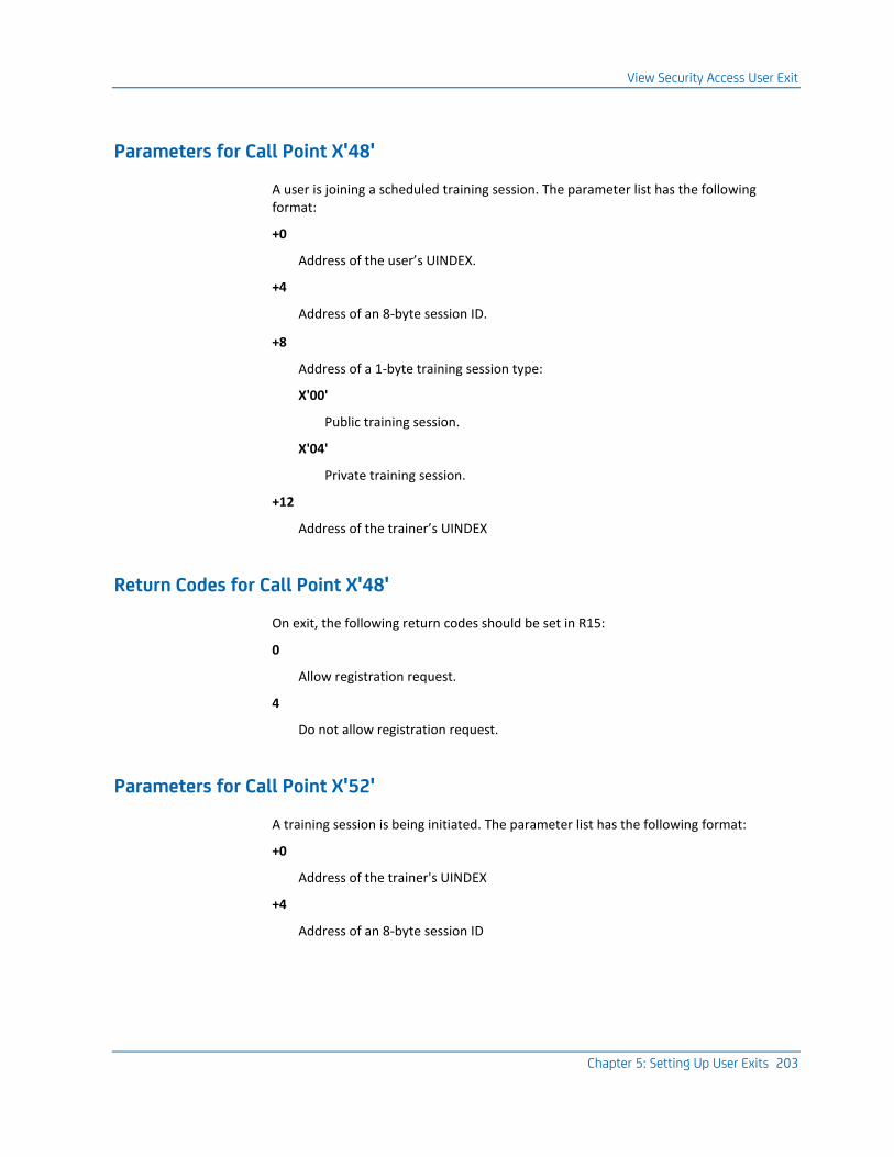
View Security Access User Exit
Chapter 5: Setting Up User Exits 203
Parameters for Call Point X'48'
A user is joining a scheduled training session. The parameter list has the following format:
+0
Address of the user’s UINDEX.
+4
Address of an 8-byte session ID.
+8
Address of a 1-byte training session type:
X'00'
Public training session.
X'04'
Private training session.
+12
Address of the trainer’s UINDEX
Return Codes for Call Point X'48'
On exit, the following return codes should be set in R15:
0
Allow registration request.
4
Do not allow registration request.
Parameters for Call Point X'52'
A training session is being initiated. The parameter list has the following format:
+0
Address of the trainer's UINDEX
+4
Address of an 8-byte session ID
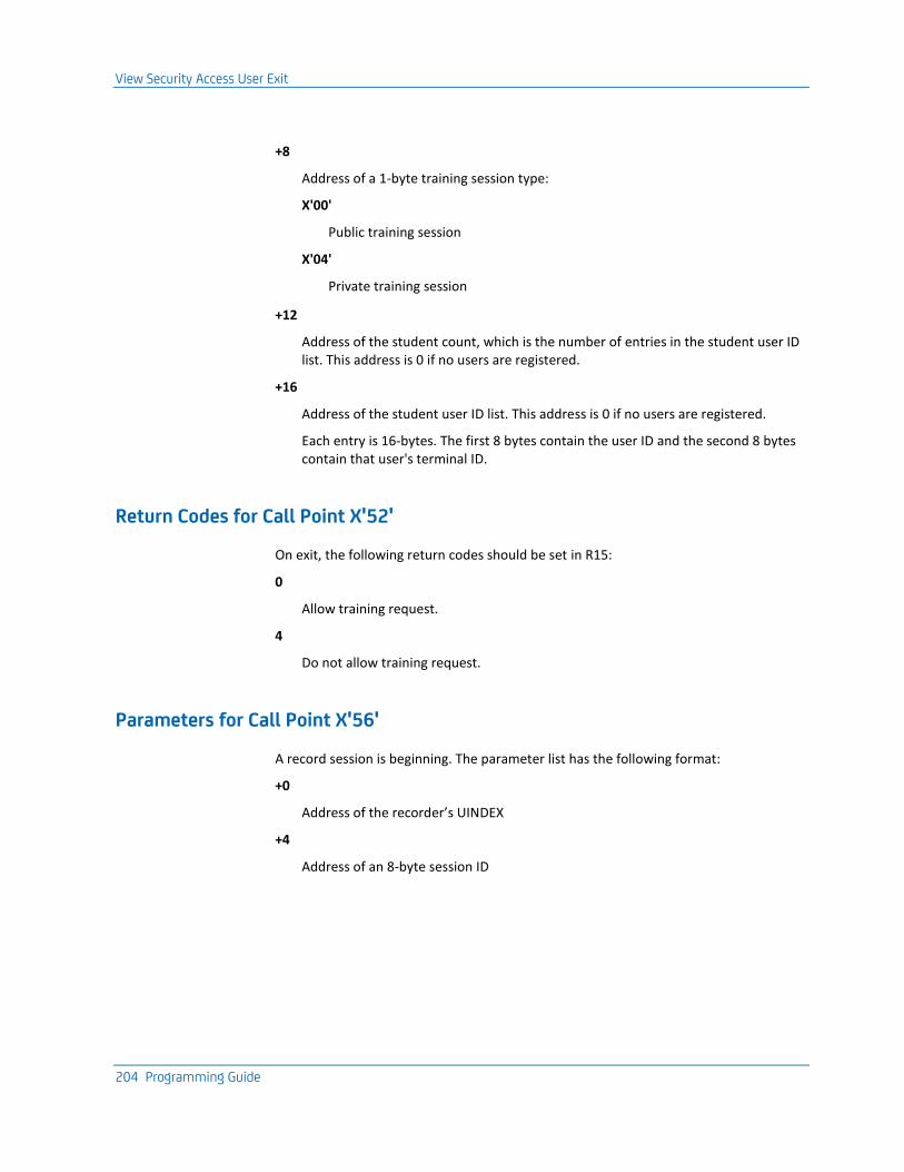
View Security Access User Exit
204 Programming Guide
+8
Address of a 1-byte training session type:
X'00'
Public training session
X'04'
Private training session
+12
Address of the student count, which is the number of entries in the student user ID list. This address is 0 if no users are registered.
+16
Address of the student user ID list. This address is 0 if no users are registered.
Each entry is 16-bytes. The first 8 bytes contain the user ID and the second 8 bytes contain that user's terminal ID.
Return Codes for Call Point X'52'
On exit, the following return codes should be set in R15:
0
Allow training request.
4
Do not allow training request.
Parameters for Call Point X'56'
A record session is beginning. The parameter list has the following format:
+0
Address of the recorder’s UINDEX
+4
Address of an 8-byte session ID
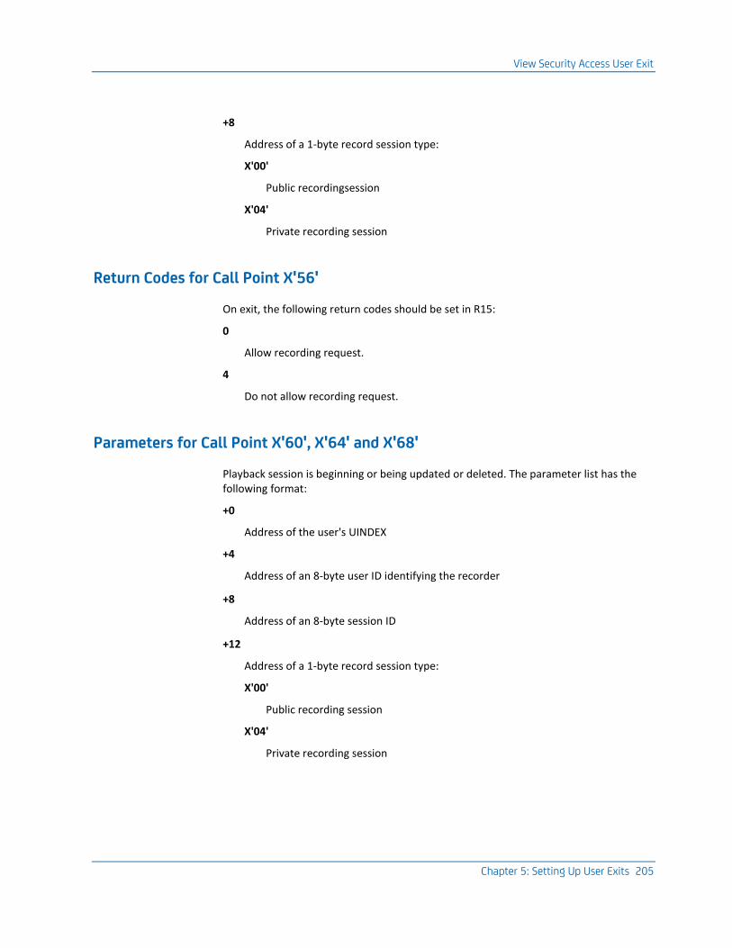
View Security Access User Exit
Chapter 5: Setting Up User Exits 205
+8
Address of a 1-byte record session type:
X'00'
Public recordingsession
X'04'
Private recording session
Return Codes for Call Point X'56'
On exit, the following return codes should be set in R15:
0
Allow recording request.
4
Do not allow recording request.
Parameters for Call Point X'60', X'64' and X'68'
Playback session is beginning or being updated or deleted. The parameter list has the following format:
+0
Address of the user's UINDEX
+4
Address of an 8-byte user ID identifying the recorder
+8
Address of an 8-byte session ID
+12
Address of a 1-byte record session type:
X'00'
Public recording session
X'04'
Private recording session
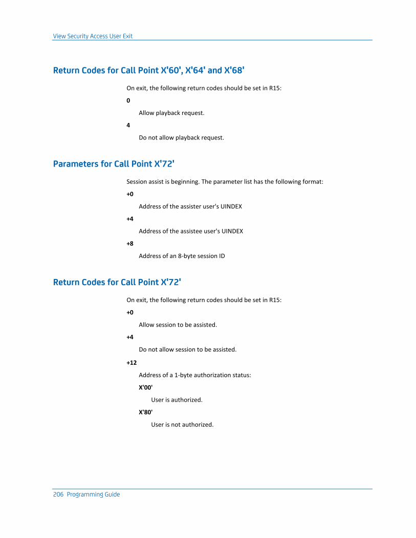
View Security Access User Exit
206 Programming Guide
Return Codes for Call Point X'60', X'64' and X'68'
On exit, the following return codes should be set in R15:
0
Allow playback request.
4
Do not allow playback request.
Parameters for Call Point X'72'
Session assist is beginning. The parameter list has the following format:
+0
Address of the assister user's UINDEX
+4
Address of the assistee user's UINDEX
+8
Address of an 8-byte session ID
Return Codes for Call Point X'72'
On exit, the following return codes should be set in R15:
+0
Allow session to be assisted.
+4
Do not allow session to be assisted.
+12
Address of a 1-byte authorization status:
X'00'
User is authorized.
X'80'
User is not authorized.
Chapter 6: Frequently Asked Questions 207
Chapter 6: Frequently Asked Questions
The following frequently asked questions (FAQs) are provided to help you better use and troubleshoot CA TPX features.
This section contains the following topics:
FAQs (see page 207)
FAQs
Q: Can I issue a z/OS modify command to send a broadcast message to CA TPX?
A: Yes. The syntax for the command is:
F tpx_started_task_name, SEND 'text',L=general_list_name
Q: How do I dynamically add virtual terminals to CA TPX?
A: Build a VTAM member to define the additional GROUP, UNIQUE, or both, virtual terminals as follows:
TPXNEW VBUILD TYPE=APPL
*TPX,UNIQUE DO NOT REMOVE - THIS COMMENT IDENTIFIES UNIQUE VIRT TERM
*
Z44IJSU0 APPL MODETAB=ISTINCLM,DLOGMOD=T3278M2,SRBEXIT=NO,EAS=1
Z44IJSU1 APPL MODETAB=ISTINCLM,DLOGMOD=T3278M2E,SRBEXIT=NO,EAS=1
Z44IJSU2 APPL MODETAB=ISTINCLM,DLOGMOD=T3278M3,SRBEXIT=NO,EAS=1
* END OF UNIQUE VIRTUAL TERMINALS
*
*TPX,GROUP DO NOT REMOVE - THIS COMMENT INDENTIFIES GROUP VIRT TERM
*
Z44IGRU0 APPL MODETAB=ISTINCLM,DLOGMOD=T3278M2,SRBEXIT=NO,EAS=1
Z44IGRU0 APPL MODETAB=ISTINCLM,DLOGMOD=T3278M2E,SRBEXIT=NO,EAS=1
Z44IGRU0 APPL MODETAB=ISTINCLM,DLOGMOD=T3278M3,SRBEXIT=NO,EAS=1
* END OF GROUP VIRTUAL TERMINALS*
Vary the new member ACTIVE in VTAM.
In TPXOPER, issue the VTADD TPXNEW command to add the newly created VTAM member TPXNEW.
FAQs
208 Programming Guide
Q: Where are the CA TPX timeouts specified?
A: Timeout values are established at the multiple levels listed below. The lowest level where information is specified is used. Levels are listed here from high to low.
System Options Table (SMRT)
Timing Parameters Detail panel (TEN0104)—All fields require values; if no values are specified, SMRT defaults are used. This panel contains User Timeout and Timeout Option fields, which allow for a two-stage timeout if the first level is a lock (L in Timeout Option field), and a Session Timeout field.
Application Characteristics Table (ACT)
Application Characteristics Detail panel (TEN0094)—This panel contains the Timeout Minutes field for an application. Specifying this field is optional.
Profile:
■ TPX User Options Detail panel (TEN0113)—This panel contains four timeout-related fields and allows for a two-stage timeout. Specifying these fields is optional; if specified, the values override the User Timeout and Timeout Option fields in the SMRT.
■ TPX Application Session Options-Profile Table Detail panel (TEN0114)—Use the Timeout Minutes field. Specifying the field is optional; if specified, the value overrides the value in the ACT (if specified) and in the Session Timeout field in the SMRT.
TPX User Maintenance
(Applicable only for user IDs defined in the administration database)
■ TPX User Options, TPX Userid Maintenance Detail panel (TEN0123)—This panel contains four timeout-related fields and allows for a two-stage timeout. Specifying these fields is optional; if specified, the values override the User Options at the Profile level and the User Timeout and Timeout Option fields in the SMRT.
■ TPX Session Options, TPX User Maintenance Detail for Session panel (TEN0124)—Use the Timeout Minutes field. Specifying this field is optional; if specified, the value overrides the Application Session Options at the Profile level, the ACT, and the User Timeout field in the SMRT.
When evaluating timeout information, you should also consider timeouts that can be defined in your applications, such as the TCP/IP INACTIVE parameter.
Q: Where can I get a summary of total active sessions? The TPXOPER command "D U" displays total active users, but requires that I tally the active sessions of all user IDs listed.
A: The z/OS console command "F tpxprocname, D U" displays a summary of the total active sessions.
FAQs
Chapter 6: Frequently Asked Questions 209
Q: When and how should an SVCDUMP of the CA TPX region be taken?
A: In general, you should take an SVCDUMP when CA TPX is in a hung state or using an excessive amount of CPU time.
Issue the following z/OS command at the system console:
DUMP COMM=(TPX LOOP DUMP)
The system issues the following response, where xx is the reply number:
xx IEE094d SPECIFY OPERANDS(S) FOR DUMP COMMAND
Reply to the console message with:
xxJOBNAME=(proc_name,),SDATA=(RGN,SQA,CSA,TRT,LSQA),
STRLIST=(STRNAME=sname,ACCESSTIME=NOLIMIT,LOCKENTRIES,LISTNUM=ALL,
ADJUNCT=CAPTURE, ENTRYDATA=SERIALIZE),
END
where
xx
Indicates the reply number
proc_name
Indicates the CA TPX procedure name.
Note: If CA TPX is not running as a VTAM generic resource, omit the STRLIST parameter.
The console dump is routed to the system dump data sets.
Q: What are the considerations for using SessionData for an application session in CA TPX?
A: The SessionData field lets you provide up to 60 characters of information to an application when the application session is started.
You can pass information using the SessionData field only if the application will accept that information from the DATA parameter on the LOGON command in the unformatted system services (USS) table.
The syntax for the LOGON command in the USS table is as follows:
LOGON APPLID(applid) DATA(........)
The application controls what data can be accepted from the DATA parameter, and thus from CA TPX SessionData.

FAQs
210 Programming Guide
CA TPX SessionData for an application session can contain CA TPX variables. For example, it can contain variables such as &USERID and &PSWD to indicate the user ID and password used for CA TPX signon (unless another user ID or password is specified for the specific application session on the session detail definition). The parameters should be separated by a comma (,) or slash (/). Specify the data in the order in which the application expects to receive it (that is, user ID first, then password, and so on).
Q: If I have an application that needs to know my physical terminal ID, how can I accomplish this using CA TPX?
A: You can use one of four possible methods to meet this requirement:
1. You can pass the original VTAM network name to an application session by using the symbolic &NETNAME specified in the SessionData field (profile-level or user-level session detail) or by using a session signon ACL/E.
Note: You can pass information using the SessionData field only if the application will accept that information from the DATA parameter of the unformatted system services (USS) table.
2. You can implement a terminal-masking rule (in a virtual terminal masking rule table) for the application (defined in the ACT table with the mask rule name) that will "map" a physical terminal ID to a virtual terminal ID where only one character is different.
For example: you can set up a rule that will map all physical terminals to a virtual terminal mask that changes only the first position of the terminal ID, but retains the remaining positions (physical terminal ID A55U0109 would "map" to Z55U0109), or some variation of this mapping logic. The application, however, will need to know that the Zxxxxxxx virtual terminals are derived from Axxxxxxx physical terminals.
3. OEM Terminal-ID Query allows you to incorporate code, as part of your application, that utilizes a special data stream sent from the application. CA TPX intercepts this data stream and responds with a data stream that contains the LUNAME of the physical terminal; no data is actually transmitted to or from the terminal. The CB0VSRC library contains two samples: CICS#OEM and TSO#OEM.
4. You can set up the application session to be a PASS session (PASS = Y in profile-level or user-level session definition) so that when a user selects the session, CA TPX "passes" the physical terminal to the session. The application communicates directly with the physical terminal as if a session manager is not in use. While in PASS mode for the application session, CA TPX functions, such as toggling between sessions, are unavailable. When the application session is terminated, CA TPX regains control of the physical terminal.
FAQs
Chapter 6: Frequently Asked Questions 211
Q: What are the benefits of using external security to determine the applications that will appear on the TPX Menu for a given user? How do I implement it?
A: The benefits are as follows:
■ CA TPX maintenance would be reduced to adding or deleting applications and profiles in the system, which in most installations is an infrequent occurrence. The user maintenance would be reduced to security system entries that are required regardless of whether you use CA TPX.
■ Customization of the signon and signoff exit function code 20 would likely be eliminated.
■ Any exceptions to the normal menu, such as additional authorizations for managers, are resolved by security. External security will manage each application and its appearance on the menu based on the set of permissions defined for the user ID. All exceptions are clearly defined in external security based on the user's position.
For information on how to implement this, see Using External Security to Determine Applications on TPX Menu in the chapter Special Features and Customization Tasks (see page 45).
In addition, the signon and signoff exit (TPXUSNSF) must be checked under function code 20 to return to CA TPX with return code 12. The default exit, as supplied, performs the functionality required. (For more information, see Signon and Signoff Exit (see page 176).)
Q: How many megabytes of Coupling Facility (CF) storage are required for the CA TPX list structure?
A: Determining the required storage involves a number of factors. Use the formulas provided by IBM for a list structure with named entries and adjunct data (this can be different depending on the CFLEVEL and CF model in use). For your hardware and software levels, see IBM documentation S/390 PR/SM Planning Guide (GA22-7236-04) or equivalent.
Determine the maximum number of members (instances of CA TPX) that can use this generic name. This number plus one gives you the maximum number of lists in the structure (commonly referred to as the list count). This is also the number of lock entries required.
CA TPX uses named entries without keys and allocates adjunct data for each entry. A single list set entry (with adjunct data) is used for each unique user that is logged on to CA TPX. Data elements are not used for unique users. Mult-users require a single list set entry for all instances of any one user ID with adjunct data and one or more data elements, which are defined with a size of 256 bytes and are allocated in 256 byte increments. The number of data elements associated with a list entry is a function of the number of instances of any one Mult-user and is limited to 16, which limits the maximum number of instances of any one Mult-user to approximately 341.
FAQs
212 Programming Guide
The amount of storage used in the data element is approximately 12 bytes per Mult-user instance. However, the element and entry ratios are set to one to minimize data element space and maximize list entry space in the structure.
These calculations will give you a close estimation of the storage required. We recommend that you monitor structure utilization, because CA TPX or IBM software maintenance and changes in your environment can affect this.
When CA TPX initializes, it issues message TPXL5101 to the CA TPX log. The message indicates the results of the connection attempt to the coupling facility structure and contains the approximate number of entries the structure will support as reported by the XES subsystem.
In addition, CA TPX provides a sample program (and the necessary JCL to invoke it) that issues the IBM IXLCSP macro. Written in assembler, the sample program asks you to provide input parameters, which are then used to calculate the number of required entries; the program then invokes the IXLCSP macro to obtain feedback from the XES subsystem regarding the approximate size of the structure required.
Q: What causes VSAM integrity errors?
A: VSAM integrity errors usually occur because:
■ Your CB0VLOAD is not APF authorized.
■ You moved, reorganized, or allocated your VSAM files or the catalog but did not run the RESET INTEGRITY batch job prior to restarting CA TPX. For sample JCL for this job, see the BATCHINI member in CB0VSRC. See also the Batch Administration Guide.
■ You are running a VSAM optimizer.
You upgraded your operating system but did not run the batch RESET INTEGRITY job against your VSAM files prior to starting CA TPX for the first time in the new operating environment.

Chapter 7: Contacting Technical Support 213
Chapter 7: Contacting Technical Support
This chapter contains information about identifying and resolving problems. Topics include the following:
■ Diagnostic Procedures
■ Contacting Technical Support
■ CA-TLC: Total License Care
■ Product Versions and Maintenance
This section contains the following topics:
Diagnostic Procedures (see page 214) CA-TLC: Total License Care (see page 216) Product Versions and Maintenance (see page 216)
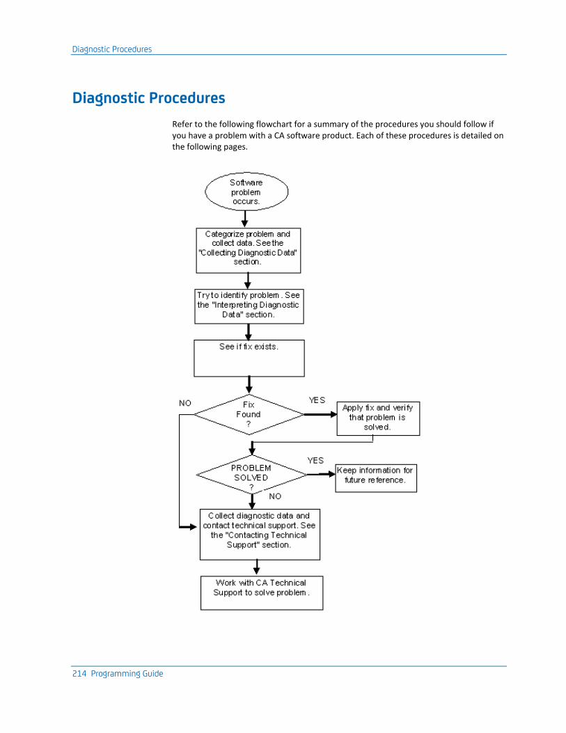
Diagnostic Procedures
214 Programming Guide
Diagnostic Procedures
Refer to the following flowchart for a summary of the procedures you should follow if you have a problem with a CA software product. Each of these procedures is detailed on the following pages.

Diagnostic Procedures
Chapter 7: Contacting Technical Support 215
Collect Diagnostic Data
The following information is helpful in diagnosing problems that might occur:
■ Control statements used to activate your product
■ JCL used to install or activate your product
■ Relevant system log or console listings
■ Relevant system dumps or product dumps
■ List of other IBM or third-party products that might be involved
■ Manufacturer, model number, and capacity of your hardware
■ Numbers and text of IBM or CA error messages associated with the problem
■ Names of panels where the problem occurs
■ Listings of all fixes applied to all relevant software, including:
– The dates fixes were applied
– Fix numbers
– Names of components to which fixes were applied
■ Short description of problems
Interpret Diagnostic Data
When you have collected the specified diagnostic data, write down your answers to the following questions:
1. What was the sequence of events prior to the error condition?
2. What were the circumstances when the problem occurred and what action did you take?
3. Has this situation occurred before? What was different then?
4. Did the problem occur after a particular PTF was applied or after a new release of the software was installed?
5. Have you recently installed a new release of the operating system?
6. Has the hardware configuration (tape drives, disk drives, and so forth) changed?
From your response to these questions and the diagnostic data, try to identify the cause and resolve the problem.
CA-TLC: Total License Care
216 Programming Guide
CA-TLC: Total License Care
Many CA software solutions use license keys or authorization codes to validate your hardware configuration. If you need assistance obtaining a license key or authorization code, contact the CA-TLC: Total License Care group through http://ca.com/support http://ca.com/support.
Product Versions and Maintenance
Customers are requested to operate only under currently supported versions of the product.
Customers with current maintenance agreements also receive ongoing product maintenance. When a new version of the product is available, a notice is sent to all current customers.

Appendix A: SMF Records 217
Appendix A: SMF Records
The records in this appendix are written to SMF if the SMF record number field on the System Options Table (SMRT) specifies an SMF record number. All records have the same SMF record number with the one-byte MONTYPE indicating the specific record type. The interval record is written on an interval specified in the SMF Logging Interval field on the SMRT. Other record types are written at particular events.
Note: Some session statistics are only available for managed sessions.
This section contains the following topics:
Record Types (see page 217) CA TPX CB0VMAC(MONSMF) (see page 218)
Record Types
The following list describes the record types:
■ X'01'—Start of CA TPX.
■ X'02'—Interval performance data.
■ X'04'—Stop record.
■ X'05'—User signs on to this product.
■ X'06'—User signs off this product.
■ X'07'—User activates application session.
■ X'08'—User deactivates application session.
■ X'09'—Session interval performance data.
■ X'0A'—Stop record.
■ X'0B'—User starts or ends session view session.
■ X'0C'—User starts or ends session assist session.
■ X'0D'—User initiates or terminates conference session.
■ X'0E'—User joins or leaves conference session.
■ X'0F'—User initiates or terminates training session.
■ X'10'—User joins or leaves training session.
■ X'11'—User starts or ends record session.
■ X'12'—User starts or ends playback session.
■ X'13'—User grants temporary View authority.

CA TPX CB0VMAC(MONSMF)
218 Programming Guide
CA TPX CB0VMAC(MONSMF)
MACRO
MONSMF ,
MONREC DS 0F MONREC LAYOUT
*
* SMF STANDARD HEADER (ALL RECORD TYPES)
*
MONRDW DC AL2(MONRLEN) LL=(RECORD LENGTH)
DC H'0' ZZ=NULL SEGMENT DESCRIPTOR
MONIND DS X z/OS=X'02' VM/GCS=X'E5'
MONSMF# DS X'00' SMF RECORD TYPE
*
MONTIME DS XL4 TIME OF ELAPSED INTERVAL (UNITS OF 1/100 SEC)
MONDATE DS XL4 DATE OF ELAPSED INTERVAL 00YYDDDF
MONSYS DS CL4 SYSID
*
* TPX STANDARD HEADER (ALL RECORD TYPES)
*
MONVER DS CL4 VERSION, RELEASE, AND MODIFICATION LEVEL
MONOFF DS XL2 OFFSET FROM MONRDW TO 1ST VARIABLE SECTION
MONTYPE DS X TYPE OF MONITOR RECORD
MONSTART EQU X'01' .. THIS IS AN TPX START RECORD
MONINTVL EQU X'02' .. THIS IS AN TPX INTERVAL RECORD
MONSTOP EQU X'04' .. THIS IS AN TPX STOP RECORD
MONTSTRT EQU X'05' .. TERMINAL SIGNON EVENT
MONTSTOP EQU X'06' .. TERMINAL SIGNOFF EVENT
MONASTRT EQU X'07' .. APPLIC'N LOGON EVENT
MONASTOP EQU X'08' .. APPLIC'N LOGOFF EVENT
MONAINTVL EQU X'09' .. APPLIC'N INTERVAL RECORD
MONSTOPA EQU X'0A' .. TPX STOP RECORD - APPLIC'N
MONVWSES EQU X'0B' .. SESSION VIEW STAT/END RECORD
MONAPPL DS CL8 APPLID OF EXECUTING SESSION MANAGER
MONCVTTZ DS XL4 CVTTZ TO ADJUST ALL STCK'S
MONBASE DS 0X START OF VARIABLE PORTION
*
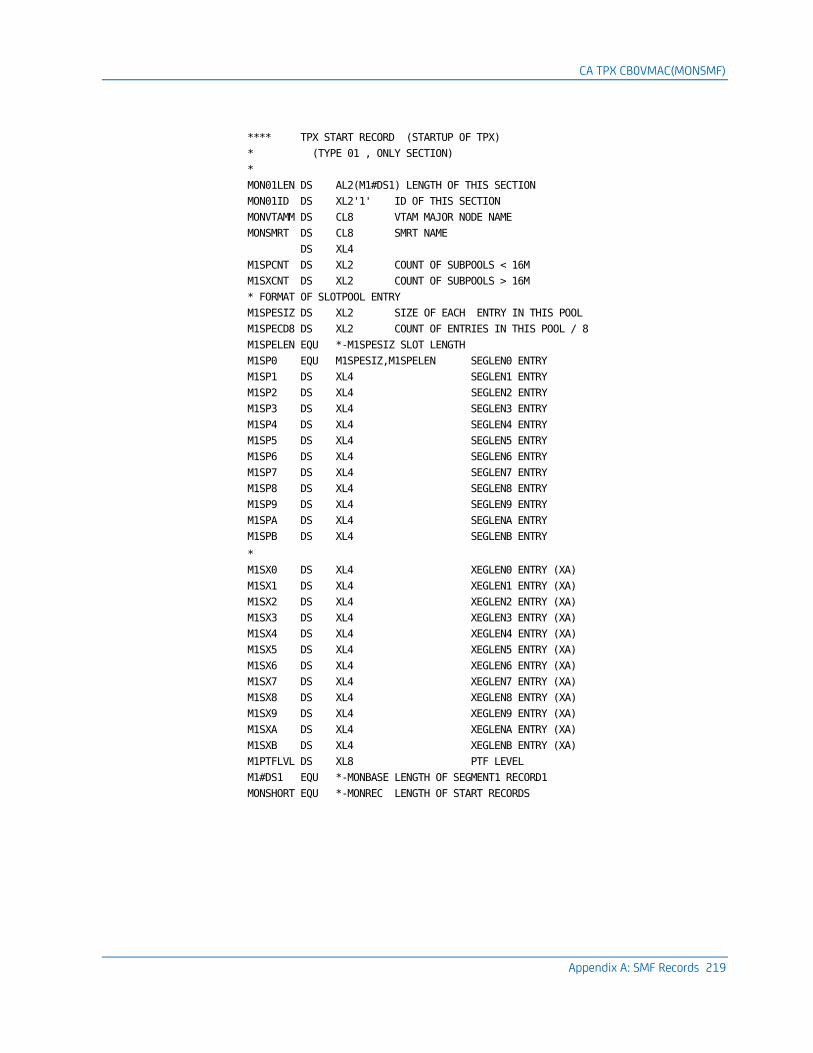
CA TPX CB0VMAC(MONSMF)
Appendix A: SMF Records 219
**** TPX START RECORD (STARTUP OF TPX)
* (TYPE 01 , ONLY SECTION)
*
MON01LEN DS AL2(M1#DS1) LENGTH OF THIS SECTION
MON01ID DS XL2'1' ID OF THIS SECTION
MONVTAMM DS CL8 VTAM MAJOR NODE NAME
MONSMRT DS CL8 SMRT NAME
DS XL4
M1SPCNT DS XL2 COUNT OF SUBPOOLS < 16M
M1SXCNT DS XL2 COUNT OF SUBPOOLS > 16M
* FORMAT OF SLOTPOOL ENTRY
M1SPESIZ DS XL2 SIZE OF EACH ENTRY IN THIS POOL
M1SPECD8 DS XL2 COUNT OF ENTRIES IN THIS POOL / 8
M1SPELEN EQU *-M1SPESIZ SLOT LENGTH
M1SP0 EQU M1SPESIZ,M1SPELEN SEGLEN0 ENTRY
M1SP1 DS XL4 SEGLEN1 ENTRY
M1SP2 DS XL4 SEGLEN2 ENTRY
M1SP3 DS XL4 SEGLEN3 ENTRY
M1SP4 DS XL4 SEGLEN4 ENTRY
M1SP5 DS XL4 SEGLEN5 ENTRY
M1SP6 DS XL4 SEGLEN6 ENTRY
M1SP7 DS XL4 SEGLEN7 ENTRY
M1SP8 DS XL4 SEGLEN8 ENTRY
M1SP9 DS XL4 SEGLEN9 ENTRY
M1SPA DS XL4 SEGLENA ENTRY
M1SPB DS XL4 SEGLENB ENTRY
*
M1SX0 DS XL4 XEGLEN0 ENTRY (XA)
M1SX1 DS XL4 XEGLEN1 ENTRY (XA)
M1SX2 DS XL4 XEGLEN2 ENTRY (XA)
M1SX3 DS XL4 XEGLEN3 ENTRY (XA)
M1SX4 DS XL4 XEGLEN4 ENTRY (XA)
M1SX5 DS XL4 XEGLEN5 ENTRY (XA)
M1SX6 DS XL4 XEGLEN6 ENTRY (XA)
M1SX7 DS XL4 XEGLEN7 ENTRY (XA)
M1SX8 DS XL4 XEGLEN8 ENTRY (XA)
M1SX9 DS XL4 XEGLEN9 ENTRY (XA)
M1SXA DS XL4 XEGLENA ENTRY (XA)
M1SXB DS XL4 XEGLENB ENTRY (XA)
M1PTFLVL DS XL8 PTF LEVEL
M1#DS1 EQU *-MONBASE LENGTH OF SEGMENT1 RECORD1
MONSHORT EQU *-MONREC LENGTH OF START RECORDS

CA TPX CB0VMAC(MONSMF)
220 Programming Guide
*
**** TPX INTERVAL AND STOP RECORD (ONLY SECTION)
* (TYPE 02, WRITTEN EVERY 'SMFINT(SMRT)' MINUTES)
* (TYPE 04, WRITTEN WHEN TPX IS TAKEN DOWN)
*
ORG MONBASE
M24LEN DS AL2(M24#DS1) LENGTH OF THIS SECTION
M24ID DS XL2'1' ID OF THIS SECTION
MONSRBT DS XL8 SRB TIME (STCK FORMAT)
MONCPU DS XL8 ASCBEJST AT INTERVAL END (STCK FORMAT)
MONPIN DS XL4 PAGE INS AT INTERVAL END (OUXBPIN)
MONPOUT DS XL4 PAGE OUTS AT INTERVAL END (OUXBPOUT)
MONMSGTI DS XL4 TOTAL TERMINAL MESSAGES INBOUND TO TPX
MONMSGTO DS XL4 TOTAL TERMINAL MESSAGES OUTBOUND FROM TPX
MONBYTTI DS XL4 TOTAL TERMINAL BYTES INBOUND TO TPX
MONBYTTO DS XL4 TOTAL TERMINAL BYTES OUTBOUND FROM TPX
MONSESTS DS XL4 TOTAL TERMINAL SESSIONS STARTED
MONSESTP DS XL4 TOTAL TERMINAL SESSIONS STOPPED
MONMSGAI DS XL4 TOTAL APPLICATION MESSAGES INBOUND TO TPX
MONMSGAO DS XL4 TOTAL APPLICATION MESSAGES OUTBOUND FROM TPX
MONBYTAI DS XL4 TOTAL APPLICATION BYTES INBOUND TO TPX
MONBYTAO DS XL4 TOTAL APPLICATION BYTES OUTBOUND FROM TPX
MONSESAS DS XL4 TOTAL APPLICATION SESSIONS STARTED
MONSESAP DS XL4 TOTAL APPLICATION SESSIONS STOPPED
M24PAD DS 0X END OF COPY FROM SMRT
MONELAP DS XL4 VALUE OF SMFINT FROM SMRT GEN
*
* DSA STATISTICS
*
MONDSAF DS XL4 BYTES OF DSA FREE TO BE USED (TOTAL-USED)
MONDSAU DS XL4 DSA USED
MONDSAH DS XL4 HIGHEST USED BYTES COUNT
M2DSAE DS XL2 EMPTY DSA ENTRIES
M2DSAR DS XL2 HIGHEST USED CONTROL RECORD COUNT
MONEGOT DS XL4
MONDSA DS 0X END OF COPY FROM SMRT
*
MONXDSAF DS XL4 XA BYTES OF DSA FREE TO BE USED (TOTAL-USED)
MONXDSAU DS XL4 XA DSA USED
MONXDSAH DS XL4 XA HIGHEST USED BYTES COUNT
MONXDSAC DS 0XL4 XA HIGHEST USED CONTROL RECORD COUNT
M2DXAE DS XL2 EMPTY DSA ENTRIES
M2DXAR DS XL2 HIGHEST USED CONTROL RECORD COUNT
MONXEGOT DS XL4 XA EMERGENCY BUFFER RELOAD COUNT
MONXDSA DS 0X XA END OF COPY FROM SMRT

CA TPX CB0VMAC(MONSMF)
Appendix A: SMF Records 221
*
* SLOTPOOL STATISTICS
*
* SLOTPOOL TOTALS
*
MONSGCNT DS XL4 NO OF STORAGE SEGMENTS
MONSGFAL DS XL4 NO OF FAILURES
MONSGBYT DS XL4 NO OF BYTES USED
MONSGHIU DS XL4 HIGHEST USED BYTES
MONSLT DS 0X END OF COPY FROM SMRT
*
MONXGCNT DS XL4 XA NO OF STORAGE SEGMENTS
MONXGFAL DS XL4 XA NO OF FAILURES
MONXGBYT DS XL4 XA NO OF BYTES USED
MONXGHIU DS XL4 XA HIGHEST USED BYTES
MONXLT DS 0X XA END OF COPY FROM SMRT
*
* SEGMENT TOTALS
*
* FORMAT OF SLOTPOOL ENTRY
MONSGREQ DS XL4 NO OF GETSTORES TEMPLATE/FIRST ENTRY
MONSGGFL DS XL4 NO OF FAILURES
MONSGCUR DS XL4 CURRENT SLOT USED COUNT
MONSGMAX DS XL4 HIGHEST SLOTS USED SO FAR
MONSGLEN EQU *-MONSGREQ SLOT LENGTH
MONS0008 EQU MONSGREQ,MONSGLEN 8 (SEGLEN0) BYTE SLOT ENTRY
MONS0016 DS XL16 16 (SEGLEN1) BYTE SLOT ENTRY
MONS0032 DS XL16 32 (SEGLEN2) BYTE SLOT ENTRY
MONS0064 DS XL16 64 (SEGLEN3) BYTE SLOT ENTRY
MONS0128 DS XL16 128 (SEGLEN4) BYTE SLOT ENTRY
MONS0256 DS XL16 256 (SEGLEN5) BYTE SLOT ENTRY
MONS0512 DS XL16 512 (SEGLEN6) BYTE SLOT ENTRY
MONS1024 DS XL16 1K (SEGLEN7) BYTE SLOT ENTRY
MONS2048 DS XL16 2K (SEGLEN8) BYTE SLOT ENTRY
MONS3072 DS XL16 3K (SEGLEN9) BYTE SLOT ENTRY
MONS4096 DS XL16 4K (SEGLENA) BYTE SLOT ENTRY
MONS8192 DS XL16 8K (SEGLENB) BYTE SLOT ENTRY
MONSCNTR EQU 12
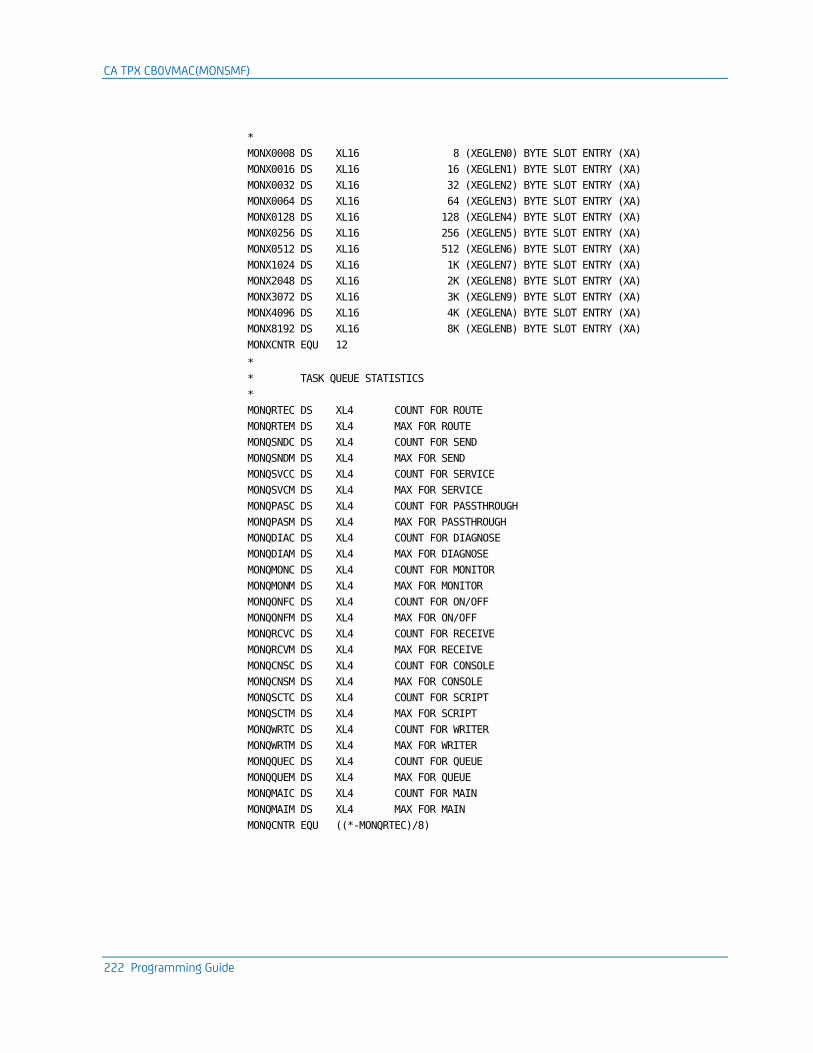
CA TPX CB0VMAC(MONSMF)
222 Programming Guide
*
MONX0008 DS XL16 8 (XEGLEN0) BYTE SLOT ENTRY (XA)
MONX0016 DS XL16 16 (XEGLEN1) BYTE SLOT ENTRY (XA)
MONX0032 DS XL16 32 (XEGLEN2) BYTE SLOT ENTRY (XA)
MONX0064 DS XL16 64 (XEGLEN3) BYTE SLOT ENTRY (XA)
MONX0128 DS XL16 128 (XEGLEN4) BYTE SLOT ENTRY (XA)
MONX0256 DS XL16 256 (XEGLEN5) BYTE SLOT ENTRY (XA)
MONX0512 DS XL16 512 (XEGLEN6) BYTE SLOT ENTRY (XA)
MONX1024 DS XL16 1K (XEGLEN7) BYTE SLOT ENTRY (XA)
MONX2048 DS XL16 2K (XEGLEN8) BYTE SLOT ENTRY (XA)
MONX3072 DS XL16 3K (XEGLEN9) BYTE SLOT ENTRY (XA)
MONX4096 DS XL16 4K (XEGLENA) BYTE SLOT ENTRY (XA)
MONX8192 DS XL16 8K (XEGLENB) BYTE SLOT ENTRY (XA)
MONXCNTR EQU 12
*
* TASK QUEUE STATISTICS
*
MONQRTEC DS XL4 COUNT FOR ROUTE
MONQRTEM DS XL4 MAX FOR ROUTE
MONQSNDC DS XL4 COUNT FOR SEND
MONQSNDM DS XL4 MAX FOR SEND
MONQSVCC DS XL4 COUNT FOR SERVICE
MONQSVCM DS XL4 MAX FOR SERVICE
MONQPASC DS XL4 COUNT FOR PASSTHROUGH
MONQPASM DS XL4 MAX FOR PASSTHROUGH
MONQDIAC DS XL4 COUNT FOR DIAGNOSE
MONQDIAM DS XL4 MAX FOR DIAGNOSE
MONQMONC DS XL4 COUNT FOR MONITOR
MONQMONM DS XL4 MAX FOR MONITOR
MONQONFC DS XL4 COUNT FOR ON/OFF
MONQONFM DS XL4 MAX FOR ON/OFF
MONQRCVC DS XL4 COUNT FOR RECEIVE
MONQRCVM DS XL4 MAX FOR RECEIVE
MONQCNSC DS XL4 COUNT FOR CONSOLE
MONQCNSM DS XL4 MAX FOR CONSOLE
MONQSCTC DS XL4 COUNT FOR SCRIPT
MONQSCTM DS XL4 MAX FOR SCRIPT
MONQWRTC DS XL4 COUNT FOR WRITER
MONQWRTM DS XL4 MAX FOR WRITER
MONQQUEC DS XL4 COUNT FOR QUEUE
MONQQUEM DS XL4 MAX FOR QUEUE
MONQMAIC DS XL4 COUNT FOR MAIN
MONQMAIM DS XL4 MAX FOR MAIN
MONQCNTR EQU ((*-MONQRTEC)/8)
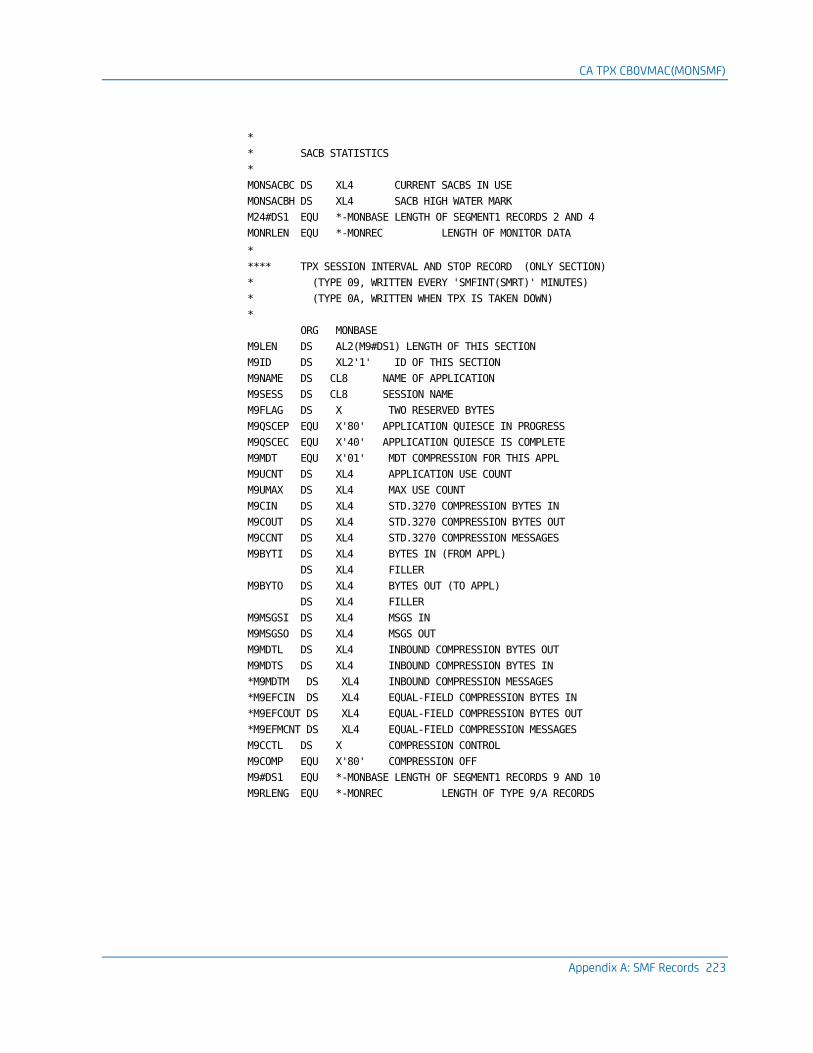
CA TPX CB0VMAC(MONSMF)
Appendix A: SMF Records 223
*
* SACB STATISTICS
*
MONSACBC DS XL4 CURRENT SACBS IN USE
MONSACBH DS XL4 SACB HIGH WATER MARK
M24#DS1 EQU *-MONBASE LENGTH OF SEGMENT1 RECORDS 2 AND 4
MONRLEN EQU *-MONREC LENGTH OF MONITOR DATA
*
**** TPX SESSION INTERVAL AND STOP RECORD (ONLY SECTION)
* (TYPE 09, WRITTEN EVERY 'SMFINT(SMRT)' MINUTES)
* (TYPE 0A, WRITTEN WHEN TPX IS TAKEN DOWN)
*
ORG MONBASE
M9LEN DS AL2(M9#DS1) LENGTH OF THIS SECTION
M9ID DS XL2'1' ID OF THIS SECTION
M9NAME DS CL8 NAME OF APPLICATION
M9SESS DS CL8 SESSION NAME
M9FLAG DS X TWO RESERVED BYTES
M9QSCEP EQU X'80' APPLICATION QUIESCE IN PROGRESS
M9QSCEC EQU X'40' APPLICATION QUIESCE IS COMPLETE
M9MDT EQU X'01' MDT COMPRESSION FOR THIS APPL
M9UCNT DS XL4 APPLICATION USE COUNT
M9UMAX DS XL4 MAX USE COUNT
M9CIN DS XL4 STD.3270 COMPRESSION BYTES IN
M9COUT DS XL4 STD.3270 COMPRESSION BYTES OUT
M9CCNT DS XL4 STD.3270 COMPRESSION MESSAGES
M9BYTI DS XL4 BYTES IN (FROM APPL)
DS XL4 FILLER
M9BYTO DS XL4 BYTES OUT (TO APPL)
DS XL4 FILLER
M9MSGSI DS XL4 MSGS IN
M9MSGSO DS XL4 MSGS OUT
M9MDTL DS XL4 INBOUND COMPRESSION BYTES OUT
M9MDTS DS XL4 INBOUND COMPRESSION BYTES IN
*M9MDTM DS XL4 INBOUND COMPRESSION MESSAGES
*M9EFCIN DS XL4 EQUAL-FIELD COMPRESSION BYTES IN
*M9EFCOUT DS XL4 EQUAL-FIELD COMPRESSION BYTES OUT
*M9EFMCNT DS XL4 EQUAL-FIELD COMPRESSION MESSAGES
M9CCTL DS X COMPRESSION CONTROL
M9COMP EQU X'80' COMPRESSION OFF
M9#DS1 EQU *-MONBASE LENGTH OF SEGMENT1 RECORDS 9 AND 10
M9RLENG EQU *-MONREC LENGTH OF TYPE 9/A RECORDS
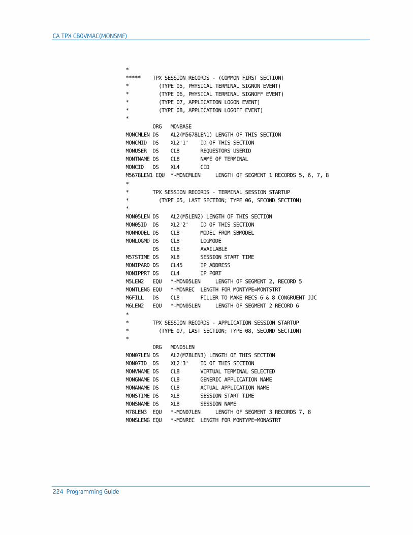
CA TPX CB0VMAC(MONSMF)
224 Programming Guide
*
***** TPX SESSION RECORDS - (COMMON FIRST SECTION)
* (TYPE 05, PHYSICAL TERMINAL SIGNON EVENT)
* (TYPE 06, PHYSICAL TERMINAL SIGNOFF EVENT)
* (TYPE 07, APPLICATION LOGON EVENT)
* (TYPE 08, APPLICATION LOGOFF EVENT)
*
ORG MONBASE
MONCMLEN DS AL2(M5678LEN1) LENGTH OF THIS SECTION
MONCMID DS XL2'1' ID OF THIS SECTION
MONUSER DS CL8 REQUESTORS USERID
MONTNAME DS CL8 NAME OF TERMINAL
MONCID DS XL4 CID
M5678LEN1 EQU *-MONCMLEN LENGTH OF SEGMENT 1 RECORDS 5, 6, 7, 8
*
* TPX SESSION RECORDS - TERMINAL SESSION STARTUP
* (TYPE 05, LAST SECTION; TYPE 06, SECOND SECTION)
*
MON05LEN DS AL2(M5LEN2) LENGTH OF THIS SECTION
MON05ID DS XL2'2' ID OF THIS SECTION
MONMODEL DS CL8 MODEL FROM SBMODEL
MONLOGMD DS CL8 LOGMODE
DS CL8 AVAILABLE
M57STIME DS XL8 SESSION START TIME
MONIPARD DS CL45 IP ADDRESS
MONIPPRT DS CL4 IP PORT
M5LEN2 EQU *-MON05LEN LENGTH OF SEGMENT 2, RECORD 5
MONTLENG EQU *-MONREC LENGTH FOR MONTYPE=MONTSTRT
M6FILL DS CL8 FILLER TO MAKE RECS 6 & 8 CONGRUENT JJC
M6LEN2 EQU *-MON05LEN LENGTH OF SEGMENT 2 RECORD 6
*
* TPX SESSION RECORDS - APPLICATION SESSION STARTUP
* (TYPE 07, LAST SECTION; TYPE 08, SECOND SECTION)
*
ORG MON05LEN
MON07LEN DS AL2(M78LEN3) LENGTH OF THIS SECTION
MON07ID DS XL2'3' ID OF THIS SECTION
MONVNAME DS CL8 VIRTUAL TERMINAL SELECTED
MONGNAME DS CL8 GENERIC APPLICATION NAME
MONANAME DS CL8 ACTUAL APPLICATION NAME
MONSTIME DS XL8 SESSION START TIME
MONSNAME DS XL8 SESSION NAME
M78LEN3 EQU *-MON07LEN LENGTH OF SEGMENT 3 RECORDS 7, 8
MONSLENG EQU *-MONREC LENGTH FOR MONTYPE=MONASTRT
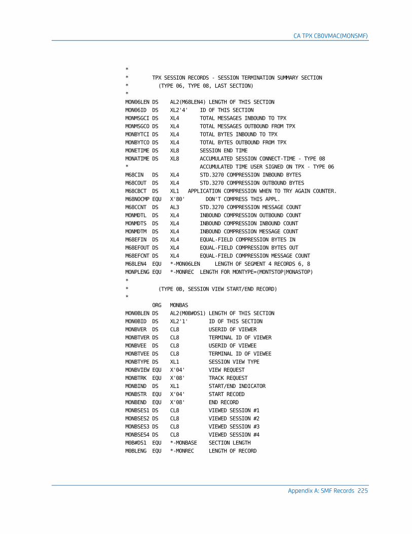
CA TPX CB0VMAC(MONSMF)
Appendix A: SMF Records 225
*
* TPX SESSION RECORDS - SESSION TERMINATION SUMMARY SECTION
* (TYPE 06, TYPE 08, LAST SECTION)
*
MON06LEN DS AL2(M68LEN4) LENGTH OF THIS SECTION
MON06ID DS XL2'4' ID OF THIS SECTION
MONMSGCI DS XL4 TOTAL MESSAGES INBOUND TO TPX
MONMSGCO DS XL4 TOTAL MESSAGES OUTBOUND FROM TPX
MONBYTCI DS XL4 TOTAL BYTES INBOUND TO TPX
MONBYTCO DS XL4 TOTAL BYTES OUTBOUND FROM TPX
MONETIME DS XL8 SESSION END TIME
MONATIME DS XL8 ACCUMULATED SESSION CONNECT-TIME - TYPE 08
* ACCUMULATED TIME USER SIGNED ON TPX - TYPE 06
M68CIN DS XL4 STD.3270 COMPRESSION INBOUND BYTES
M68COUT DS XL4 STD.3270 COMPRESSION OUTBOUND BYTES
M68CBCT DS XL1 APPLICATION COMPRESSION WHEN TO TRY AGAIN COUNTER.
M68NOCMP EQU X'80' DON'T COMPRESS THIS APPL.
M68CCNT DS AL3 STD.3270 COMPRESSION MESSAGE COUNT
MONMDTL DS XL4 INBOUND COMPRESSION OUTBOUND COUNT
MONMDTS DS XL4 INBOUND COMPRESSION INBOUND COUNT
MONMDTM DS XL4 INBOUND COMPRESSION MESSAGE COUNT
M68EFIN DS XL4 EQUAL-FIELD COMPRESSION BYTES IN
M68EFOUT DS XL4 EQUAL-FIELD COMPRESSION BYTES OUT
M68EFCNT DS XL4 EQUAL-FIELD COMPRESSION MESSAGE COUNT
M68LEN4 EQU *-MON06LEN LENGTH OF SEGMENT 4 RECORDS 6, 8
MONPLENG EQU *-MONREC LENGTH FOR MONTYPE=(MONTSTOP|MONASTOP)
*
* (TYPE 0B, SESSION VIEW START/END RECORD)
*
ORG MONBAS
MON0BLEN DS AL2(M0B#DS1) LENGTH OF THIS SECTION
MON0BID DS XL2'1' ID OF THIS SECTION
MONBVER DS CL8 USERID OF VIEWER
MONBTVER DS CL8 TERMINAL ID OF VIEWER
MONBVEE DS CL8 USERID OF VIEWEE
MONBTVEE DS CL8 TERMINAL ID OF VIEWEE
MONBTYPE DS XL1 SESSION VIEW TYPE
MONBVIEW EQU X'04' VIEW REQUEST
MONBTRK EQU X'08' TRACK REQUEST
MONBIND DS XL1 START/END INDICATOR
MONBSTR EQU X'04' START RECOED
MONBEND EQU X'08' END RECORD
MONBSES1 DS CL8 VIEWED SESSION #1
MONBSES2 DS CL8 VIEWED SESSION #2
MONBSES3 DS CL8 VIEWED SESSION #3
MONBSES4 DS CL8 VIEWED SESSION #4
M0B#DS1 EQU *-MONBASE SECTION LENGTH
M0BLENG EQU *-MONREC LENGTH OF RECORD
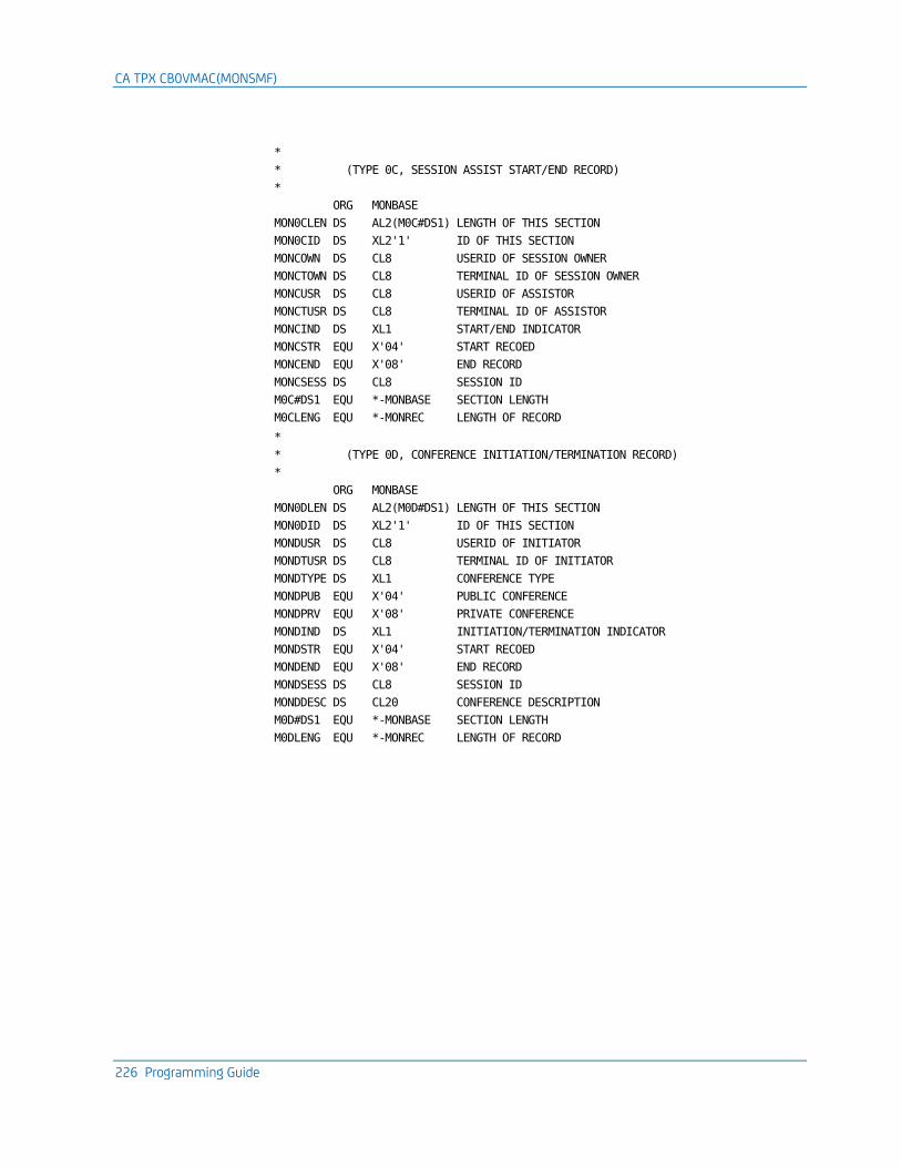
CA TPX CB0VMAC(MONSMF)
226 Programming Guide
*
* (TYPE 0C, SESSION ASSIST START/END RECORD)
*
ORG MONBASE
MON0CLEN DS AL2(M0C#DS1) LENGTH OF THIS SECTION
MON0CID DS XL2'1' ID OF THIS SECTION
MONCOWN DS CL8 USERID OF SESSION OWNER
MONCTOWN DS CL8 TERMINAL ID OF SESSION OWNER
MONCUSR DS CL8 USERID OF ASSISTOR
MONCTUSR DS CL8 TERMINAL ID OF ASSISTOR
MONCIND DS XL1 START/END INDICATOR
MONCSTR EQU X'04' START RECOED
MONCEND EQU X'08' END RECORD
MONCSESS DS CL8 SESSION ID
M0C#DS1 EQU *-MONBASE SECTION LENGTH
M0CLENG EQU *-MONREC LENGTH OF RECORD
*
* (TYPE 0D, CONFERENCE INITIATION/TERMINATION RECORD)
*
ORG MONBASE
MON0DLEN DS AL2(M0D#DS1) LENGTH OF THIS SECTION
MON0DID DS XL2'1' ID OF THIS SECTION
MONDUSR DS CL8 USERID OF INITIATOR
MONDTUSR DS CL8 TERMINAL ID OF INITIATOR
MONDTYPE DS XL1 CONFERENCE TYPE
MONDPUB EQU X'04' PUBLIC CONFERENCE
MONDPRV EQU X'08' PRIVATE CONFERENCE
MONDIND DS XL1 INITIATION/TERMINATION INDICATOR
MONDSTR EQU X'04' START RECOED
MONDEND EQU X'08' END RECORD
MONDSESS DS CL8 SESSION ID
MONDDESC DS CL20 CONFERENCE DESCRIPTION
M0D#DS1 EQU *-MONBASE SECTION LENGTH
M0DLENG EQU *-MONREC LENGTH OF RECORD

CA TPX CB0VMAC(MONSMF)
Appendix A: SMF Records 227
*
* (TYPE 0E, ENTER/LEAVE CONFERENCE RECORD)
*
ORG MONBASE
MON0ELEN DS AL2(M0E#DS1) LENGTH OF THIS SECTION
MON0EID DS XL2'1' ID OF THIS SECTION
MONEOWN DS CL8 USERID OF INITIATOR
MONETOWN DS CL8 TERMINAL ID OF INITIATOR
MONEUSR DS CL8 USERID OF PARTICIPANT
MONETUSR DS CL8 TERMINAL ID OF PARTICIPANT
MONETYPE DS XL1 CONFERENCE TYPE
MONEPUB EQU X'04' PUBLIC CONFERENCE
MONEPRV EQU X'08' PRIVATE CONFERENCE
MONEIND DS XL1 ENTER/LEAVE INDICATOR
MONESTR EQU X'04' START RECORD
MONEEND EQU X'08' END RECORD
MONESESS DS CL8 SESSION ID
MONEDESC DS CL20 CONFERENCE DESCRIPTION
M0E#DS1 EQU *-MONBASE SECTION LENGTH
M0ELENG EQU *-MONREC LENGTH OF RECORD
*
* (TYPE 0F, TRAINING SESSION INITIATION/TERMINATION RECORD)
*
ORG MONBASE
MON0FLEN DS AL2(M0F#DS1) LENGTH OF THIS SECTION
MON0FID DS XL2'1' ID OF THIS SECTION
MONFUSR DS CL8 USERID OF INITIATOR
MONFTUSR DS CL8 TERMINAL ID OF INITIATOR
MONFTYPE DS XL1 TRAINING SESSION TYPE
MONFPUB EQU X'04' PUBLIC TRAINING SESSION
MONFPRV EQU X'08' PRIVATE TRAINING SESSION
MONFIND DS XL1 INITIATION/TERMINATION INDICATOR
MONFSTR EQU X'04' START RECOED
MONFEND EQU X'08' END RECORD
MONFSESS DS CL8 SESSION ID
MONFDESC DS CL20 TRAINING SESSION DESCRIPTION
M0F#DS1 EQU *-MONBASE SECTION LENGTH
M0FLENG EQU *-MONREC LENGTH OF RECORD
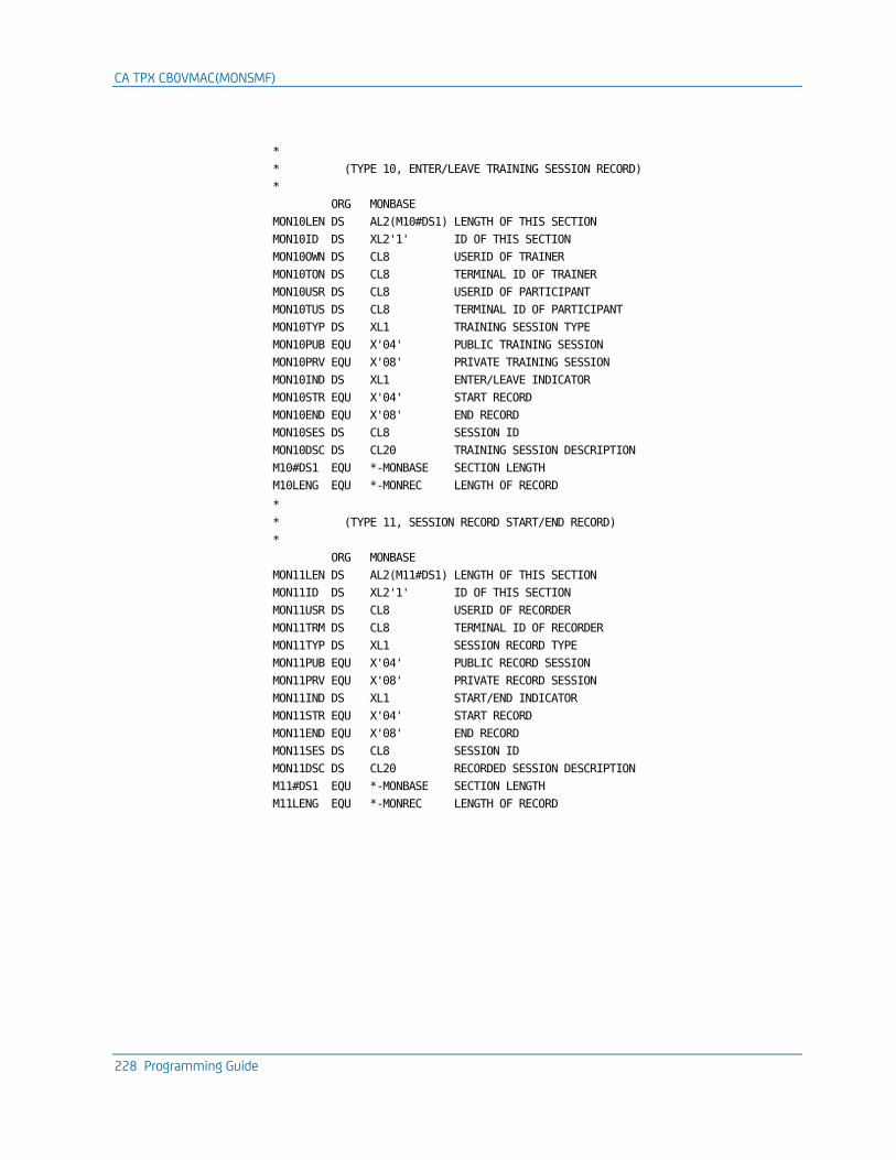
CA TPX CB0VMAC(MONSMF)
228 Programming Guide
*
* (TYPE 10, ENTER/LEAVE TRAINING SESSION RECORD)
*
ORG MONBASE
MON10LEN DS AL2(M10#DS1) LENGTH OF THIS SECTION
MON10ID DS XL2'1' ID OF THIS SECTION
MON10OWN DS CL8 USERID OF TRAINER
MON10TON DS CL8 TERMINAL ID OF TRAINER
MON10USR DS CL8 USERID OF PARTICIPANT
MON10TUS DS CL8 TERMINAL ID OF PARTICIPANT
MON10TYP DS XL1 TRAINING SESSION TYPE
MON10PUB EQU X'04' PUBLIC TRAINING SESSION
MON10PRV EQU X'08' PRIVATE TRAINING SESSION
MON10IND DS XL1 ENTER/LEAVE INDICATOR
MON10STR EQU X'04' START RECORD
MON10END EQU X'08' END RECORD
MON10SES DS CL8 SESSION ID
MON10DSC DS CL20 TRAINING SESSION DESCRIPTION
M10#DS1 EQU *-MONBASE SECTION LENGTH
M10LENG EQU *-MONREC LENGTH OF RECORD
*
* (TYPE 11, SESSION RECORD START/END RECORD)
*
ORG MONBASE
MON11LEN DS AL2(M11#DS1) LENGTH OF THIS SECTION
MON11ID DS XL2'1' ID OF THIS SECTION
MON11USR DS CL8 USERID OF RECORDER
MON11TRM DS CL8 TERMINAL ID OF RECORDER
MON11TYP DS XL1 SESSION RECORD TYPE
MON11PUB EQU X'04' PUBLIC RECORD SESSION
MON11PRV EQU X'08' PRIVATE RECORD SESSION
MON11IND DS XL1 START/END INDICATOR
MON11STR EQU X'04' START RECORD
MON11END EQU X'08' END RECORD
MON11SES DS CL8 SESSION ID
MON11DSC DS CL20 RECORDED SESSION DESCRIPTION
M11#DS1 EQU *-MONBASE SECTION LENGTH
M11LENG EQU *-MONREC LENGTH OF RECORD
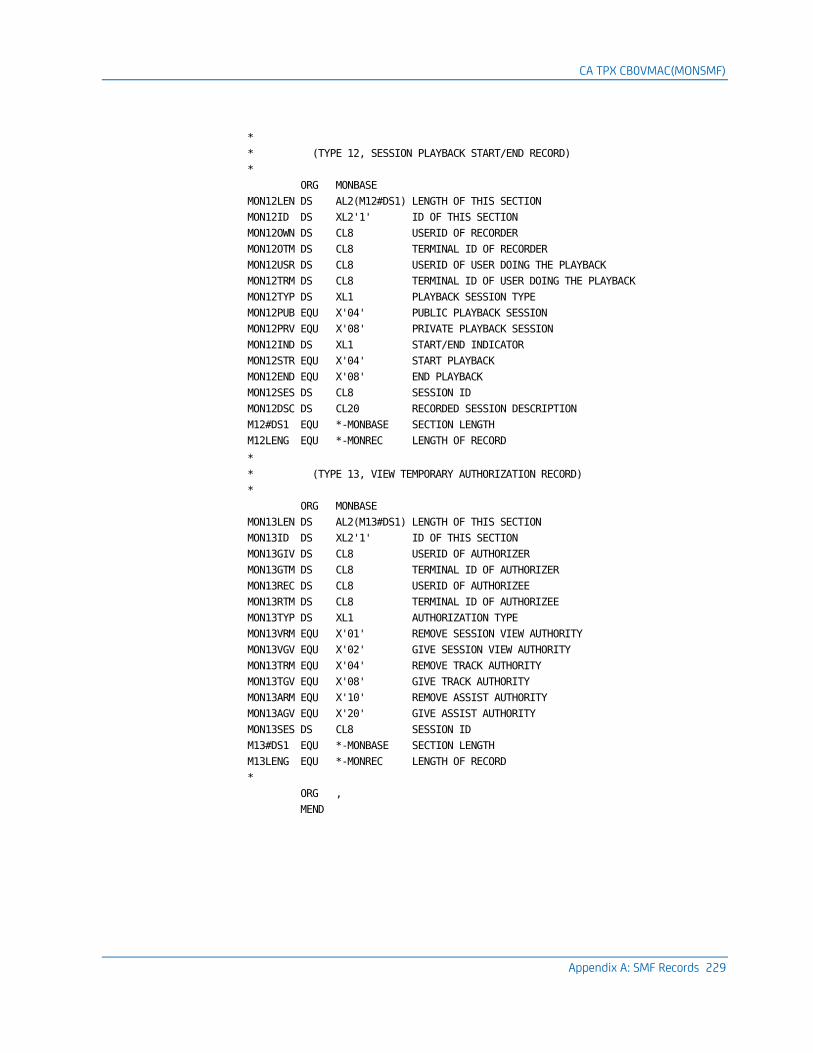
CA TPX CB0VMAC(MONSMF)
Appendix A: SMF Records 229
*
* (TYPE 12, SESSION PLAYBACK START/END RECORD)
*
ORG MONBASE
MON12LEN DS AL2(M12#DS1) LENGTH OF THIS SECTION
MON12ID DS XL2'1' ID OF THIS SECTION
MON12OWN DS CL8 USERID OF RECORDER
MON12OTM DS CL8 TERMINAL ID OF RECORDER
MON12USR DS CL8 USERID OF USER DOING THE PLAYBACK
MON12TRM DS CL8 TERMINAL ID OF USER DOING THE PLAYBACK
MON12TYP DS XL1 PLAYBACK SESSION TYPE
MON12PUB EQU X'04' PUBLIC PLAYBACK SESSION
MON12PRV EQU X'08' PRIVATE PLAYBACK SESSION
MON12IND DS XL1 START/END INDICATOR
MON12STR EQU X'04' START PLAYBACK
MON12END EQU X'08' END PLAYBACK
MON12SES DS CL8 SESSION ID
MON12DSC DS CL20 RECORDED SESSION DESCRIPTION
M12#DS1 EQU *-MONBASE SECTION LENGTH
M12LENG EQU *-MONREC LENGTH OF RECORD
*
* (TYPE 13, VIEW TEMPORARY AUTHORIZATION RECORD)
*
ORG MONBASE
MON13LEN DS AL2(M13#DS1) LENGTH OF THIS SECTION
MON13ID DS XL2'1' ID OF THIS SECTION
MON13GIV DS CL8 USERID OF AUTHORIZER
MON13GTM DS CL8 TERMINAL ID OF AUTHORIZER
MON13REC DS CL8 USERID OF AUTHORIZEE
MON13RTM DS CL8 TERMINAL ID OF AUTHORIZEE
MON13TYP DS XL1 AUTHORIZATION TYPE
MON13VRM EQU X'01' REMOVE SESSION VIEW AUTHORITY
MON13VGV EQU X'02' GIVE SESSION VIEW AUTHORITY
MON13TRM EQU X'04' REMOVE TRACK AUTHORITY
MON13TGV EQU X'08' GIVE TRACK AUTHORITY
MON13ARM EQU X'10' REMOVE ASSIST AUTHORITY
MON13AGV EQU X'20' GIVE ASSIST AUTHORITY
MON13SES DS CL8 SESSION ID
M13#DS1 EQU *-MONBASE SECTION LENGTH
M13LENG EQU *-MONREC LENGTH OF RECORD
*
ORG ,
MEND

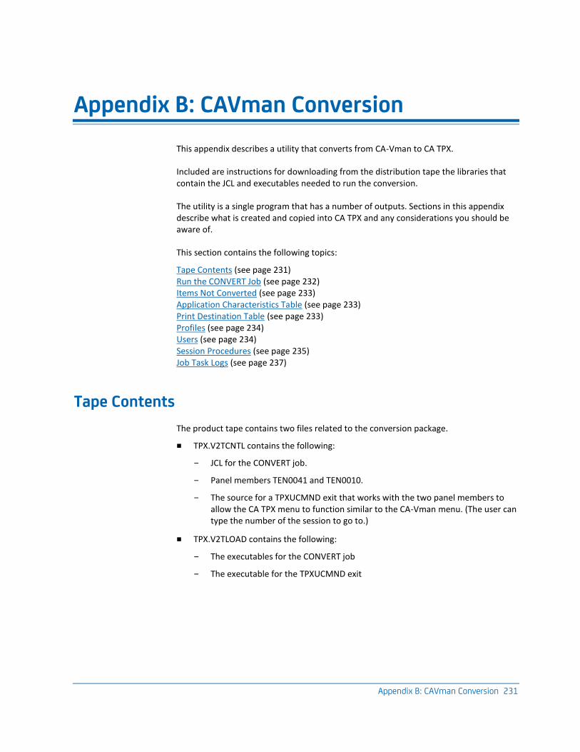
Appendix B: CAVman Conversion 231
Appendix B: CAVman Conversion
This appendix describes a utility that converts from CA-Vman to CA TPX.
Included are instructions for downloading from the distribution tape the libraries that contain the JCL and executables needed to run the conversion.
The utility is a single program that has a number of outputs. Sections in this appendix describe what is created and copied into CA TPX and any considerations you should be aware of.
This section contains the following topics:
Tape Contents (see page 231) Run the CONVERT Job (see page 232) Items Not Converted (see page 233) Application Characteristics Table (see page 233) Print Destination Table (see page 233) Profiles (see page 234) Users (see page 234) Session Procedures (see page 235) Job Task Logs (see page 237)
Tape Contents
The product tape contains two files related to the conversion package.
■ TPX.V2TCNTL contains the following:
– JCL for the CONVERT job.
– Panel members TEN0041 and TEN0010.
– The source for a TPXUCMND exit that works with the two panel members to allow the CA TPX menu to function similar to the CA-Vman menu. (The user can type the number of the session to go to.)
■ TPX.V2TLOAD contains the following:
– The executables for the CONVERT job
– The executable for the TPXUCMND exit
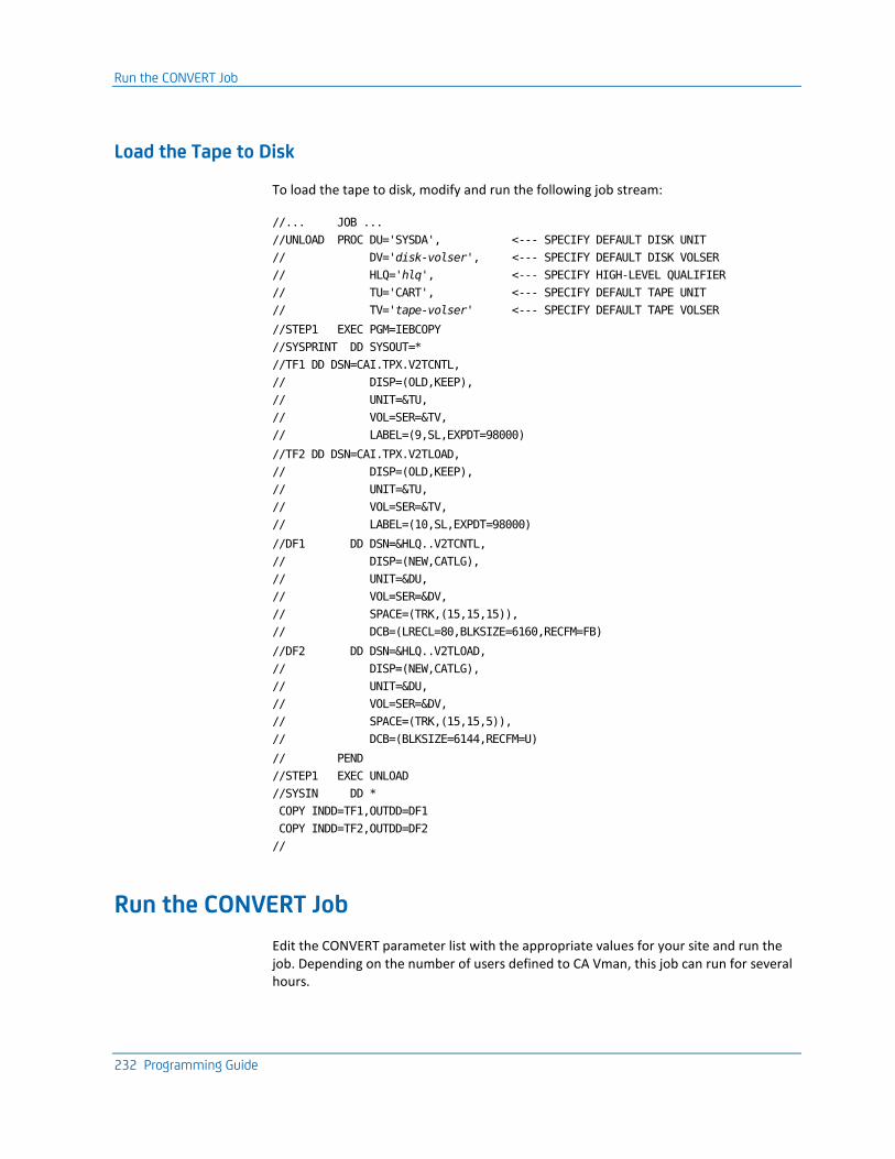
Run the CONVERT Job
232 Programming Guide
Load the Tape to Disk
To load the tape to disk, modify and run the following job stream:
//... JOB ...
//UNLOAD PROC DU='SYSDA', <--- SPECIFY DEFAULT DISK UNIT
// DV='disk-volser', <--- SPECIFY DEFAULT DISK VOLSER
// HLQ='hlq', <--- SPECIFY HIGH-LEVEL QUALIFIER
// TU='CART', <--- SPECIFY DEFAULT TAPE UNIT
// TV='tape-volser' <--- SPECIFY DEFAULT TAPE VOLSER
//STEP1 EXEC PGM=IEBCOPY
//SYSPRINT DD SYSOUT=*
//TF1 DD DSN=CAI.TPX.V2TCNTL,
// DISP=(OLD,KEEP),
// UNIT=&TU,
// VOL=SER=&TV,
// LABEL=(9,SL,EXPDT=98000)
//TF2 DD DSN=CAI.TPX.V2TLOAD,
// DISP=(OLD,KEEP),
// UNIT=&TU,
// VOL=SER=&TV,
// LABEL=(10,SL,EXPDT=98000)
//DF1 DD DSN=&HLQ..V2TCNTL,
// DISP=(NEW,CATLG),
// UNIT=&DU,
// VOL=SER=&DV,
// SPACE=(TRK,(15,15,15)),
// DCB=(LRECL=80,BLKSIZE=6160,RECFM=FB)
//DF2 DD DSN=&HLQ..V2TLOAD,
// DISP=(NEW,CATLG),
// UNIT=&DU,
// VOL=SER=&DV,
// SPACE=(TRK,(15,15,5)),
// DCB=(BLKSIZE=6144,RECFM=U)
// PEND
//STEP1 EXEC UNLOAD
//SYSIN DD *
COPY INDD=TF1,OUTDD=DF1
COPY INDD=TF2,OUTDD=DF2
//
Run the CONVERT Job
Edit the CONVERT parameter list with the appropriate values for your site and run the job. Depending on the number of users defined to CA Vman, this job can run for several hours.
Items Not Converted
Appendix B: CAVman Conversion 233
Items Not Converted
Anything not discussed in the appendix is not converted. For other items needed to fully prepare CA TPX for your site (for example the VTAM major node and the System Options Table), see the remaining chapters of this guide.
Application Characteristics Table
One entry is built for each VTAM application defined to CA-Vman into an Application Characteristics Table (ACT) called ACTCNVT.
The entry is assigned a virtual terminal type of group unless CLSDST/PASS ISSUED is set to YES in CA-Vman for any of the logical application definitions defined for this VTAM application.
Other fields in the Logical Applications definitions from CA-Vman are converted into session records at either the profile or the user level.
These fields include:
■ APPL DESCRIPTION
■ SESSION NAME
■ AUTO START SESSION
■ APPL SORT SEQUENCE
■ SESSION IDLE TIMEOUT
■ LOGON SESSION PROC
■ LOGON PARAMETER
■ MULTI-SESSION ALLOWED
Print Destination Table
One entry is built for each logical printer defined to CA-Vman into a Print Destination Table called PRTBCNVT. Each entry contains the VTAM Printer ID associated with the particular logical printer in CA-Vman.
If the logical printer name is greater than eight characters or it contains a comma (,), period (.), semi-colon (;) or embedded blank ( ), a new logical printer name is generated for the CA TPX system in the following format.
P#nnnnnn
where nnnnnn is 000001 through 999999

Profiles
234 Programming Guide
Profiles
For each profile defined to CA-Vman a profile is created in CA TPX. Each CA TPX profile contains a minimum of the user level information record, as well as one record for each session defined to the profile.
Users
For each user defined to CA-Vman a user is created in CA TPX. Each CA TPX user contains a minimum of the user level information record, the profile (if any) assigned to the user and one record for each session which is either defined at the user level or is defined at the profile level but has overrides at the user level.
User Level Information
CA-Vman fields that are converted include:
■ PROFILE NAME
■ MAXIMUM # OF SESSIONS
■ LOGICAL PRINTER ID
■ OPERATOR COMMAND AUTHORITY
■ USERADM COMMAND AUTHORITY
Command Authority
If the CA-Vman profile/user specifies YES for OPERATOR COMMAND AUTHORITY, then they are assigned a CA TPX Operator Command Class of O. Otherwise they are assigned D. These classes are defined in the distributed Operator Command Class Table.
If the CA-Vman profile/user specifies YES for USERADM COMMAND AUTHORITY, then they will be assigned a CA TPX Update Class of P. Otherwise they are assigned D. These classes are defined in the distributed User Self-Maintenance Update Class Table
Session Procedures
Appendix B: CAVman Conversion 235
Session Level Information
The CA-Vman fields that are converted include:
■ SESSION NAME
■ APPL DESCRIPTION
■ AUTO START SESSION
■ APPL SORT SEQUENCE
■ SESSION IDLE TIMEOUT
■ LOGON SESSION PROC
■ LOGON PARAMETER
■ MULTI-SESSION ALLOWED
■ SESSION PROCEDURE PARMS
Session Names
If the session name is greater than eight characters or it contains a comma (,), period (.), semi-colon (;), left parenthesis ((), right parenthesis ()) or embedded blank, a new session name is generated for the CA TPX system in the following format:
S#nnnnnn
where nnnnnn is 000001 through 999999.
Session Procedures
There are differences in the naming of session scripts and the functionality available in the scripts between the two products. This section describes the actions that are taken by the conversion program. Carefully review the results of conversion to make sure the desired results are obtained.
Session Procedure Naming
CA Vman global procedures keep their names. Because CA TPX does not have the concept of global procedures, the procedure name is "plugged" into the session record at either the profile or the user level (whichever defines the session).
Session Procedures
236 Programming Guide
CA TPX does not have the concept of local procedures for each user. You cannot have the same named procedure for different users and/or at the global level. Therefore, all local procedures are renamed to the format:
U#nnnnnn
where nnnnnn is 000001 through 999999.
SPL Procedures
All SPL procedures are translated into ACL/E language and stored in the CA TPX ACLLIB that is referenced in the convert job stream.
The converted ACL member contains the SPL statement as a comment followed by the executable ACL statement and/or any warnings or errors concerning the conversion of that statement.
As the statements are converted, CA-Vman procedure parameters are changed to either CA TPX system parameters or session level parameters 1 through 8. These show as &p1 through &p8. A comment statement follows the ACL statement to indicate the identity.
Two partitioned data sets are created in the TASK5 of the convert job:
GINDEX
Contains a member for each global procedure that is converted and contains any parameters that needed to be converted. The member indicates the new &p name given to that parameter.
UINDEX
Contains a member for each user who has local procedures that were converted. The member contains the identity of each local procedure converted, as well as the new U# name for that procedure and any new &p names given to parameters used in that procedure.
Procedure Parameters
CA Vman system standard parameters are changed to their CA TPX equivalent variables as follows:
CA Vman CA TPX
&ZUSER &USERID
&ZPSWD &PSWD
&ZTERM &NETNAME
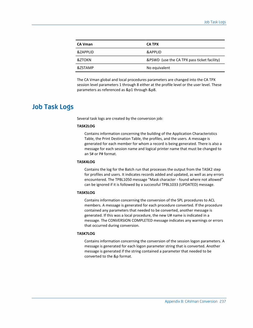
Job Task Logs
Appendix B: CAVman Conversion 237
CA Vman CA TPX
&ZAPPLID &APPLID
&ZTOKN &PSWD (use the CA TPX pass ticket facility)
&ZSTAMP No equivalent
The CA Vman global and local procedures parameters are changed into the CA TPX session level parameters 1 through 8 either at the profile level or the user level. These parameters as referenced as &p1 through &p8.
Job Task Logs
Several task logs are created by the conversion job:
TASK2LOG
Contains information concerning the building of the Application Characteristics Table, the Print Destination Table, the profiles, and the users. A message is generated for each member for whom a record is being generated. There is also a message for each session name and logical printer name that must be changed to an S# or P# format.
TASK4LOG
Contains the log for the Batch run that processes the output from the TASK2 step for profiles and users. It indicates records added and updated, as well as any errors encountered. The TPBL1050 message "Mask character - found where not allowed" can be ignored if it is followed by a successful TPBL1033 (UPDATED) message.
TASK5LOG
Contains information concerning the conversion of the SPL procedures to ACL members. A message is generated for each procedure converted. If the procedure contained any parameters that needed to be converted, another message is generated. If this was a local procedure, the new U# name is indicated in a message. The CONVERSION COMPLETED message indicates any warnings or errors that occurred during conversion.
TASK7LOG
Contains information concerning the conversion of the session logon parameters. A message is generated for each logon parameter string that is converted. Another message is generated if the string contained a parameter that needed to be converted to the &p format.
Job Task Logs
238 Programming Guide
TASK8LOG
Contains the log for the Batch run that processes the output from the TASK7 step for logon parameters. This log contains the same type of information mentioned for TASK4LOG.
Index 239
Index
3
31-bit addressing • 131
A
ACB selection exit • 137 access method control blocks (ACBs) • 78, 113, 137 ACL parameter exit • 139 ACL/ESee Automated Conversation
Language/Extended (ACL/E) • 87 addressing, 31-bit • 131 Advanced Data Compression (ADC) • 91, 92, 93
displaying statistics • 93 inbound • 91 outbound • 92 outbound stripping • 92 overriding ACT settings • 92 overview • 91 turning on • 92
affinity for CA TPX regions • 46 using • 46
Affinity for CA TPX regions • 177 failure of • 177
application characteristics table (ACT) • 87, 91 application definitions • 71, 124, 125, 126, 128
for NetSpy • 126 for Netview/NCCF • 125 for the IBM Information Network • 124 for TSO • 126 for VSPC • 128 statements • 71
applications • 72, 75, 76, 87, 107, 108, 109, 117 controlling sessions for • 87 forcing logon mode tables • 76 group • 108 OPENGATE • 87 shared • 107 terminal models • 72, 75, 109, 117
APTPX member of SYS1.VTAMLST data set • 68 ATTR statement • 23, 26 attributes, panel • 26, 27
characters • 26 COLOR • 27 FORMAT • 27 INTENSE • 27
MDT • 27 NUM • 27 OUTLINE • 27 SKIP • 27 TYPE • 27
authorization codes, obtaining • 216 authorized path facility • 72 Automated Conversation Language/Extended
(ACL/E) • 23, 87, 88 control programs • 88 creating customized panels with • 23 displaying customized panels with • 23 OPENGATE and • 87 variables for OPENGATE • 88
B
below-the-line storage • 77, 80 BODY statement • 24, 30
C
CA 7 application • 108 CA ACF2 • 49, 57, 59, 61, 62, 65, 66, 68 CA IDMS application • 108 CA Remote Console for MVS • 107 CA ROSCOE application • 107 CA STX application • 60, 107
access through CA TPX security • 60 defining as shared application • 107
CA Top Secret • 49, 62, 65, 67, 68 CA Vman • 231
converting from • 231 CA-TLC (CA Total License Care) • 216 CB0VSRC data set • 68, 72, 76, 112, 117 characters, attribute • 26 CICS application • 75, 109 COLOR attribute • 27 command exit • 141 command simulation exit • 144 control users • 90 controlling application sessions • 87 converting from CA Vman • 231 Coupling Facility • 207
storage required in • 207
240 Programming Guide
D
data sets • 47, 68, 72, 74, 76, 112, 117 CB0VSRC • 72, 76, 117 CB0VSRC data set • 68 SYS1.VTAMLST • 47, 68, 74 TPXLGMOD member of CB0VSRC • 72, 112
date on CA TPX panels • 33 defining • 107, 108, 125
group applications • 108 shared applications • 107 terminals • 125
diagnostic • 214, 215 data, collecting • 215 data, interpreting • 215 procedures • 214
double-byte character set (DBCS) terminals • 27 dynamic storage area • 76, 81
adjusting • 81 description of • 76
E
EBCDIC character codes • 22 encrypt/decrypt exit • 145 end section, in panel definitions • 33 enhanced security • 57, 61 error processing exit • 146 establishing affinity • 47
for a user • 47 with an exit • 47
exitsSee user exits • 129 external security • 207
F
fields, attributes of • 27 input • 27 numeric • 27 output • 27 text • 27
FORMAT attribute • 27
G
group applications • 108
H
hosts, running CA TPX on multiple • 47, 177
I
IENMxxxx messages • 89 IIPS application • 108 IMS application • 75 inbound compression • 91 INIT statement • 24, 32 initialization section in panel definitions • 32 input fields • 27 INTENSE attribute • 27
J
Julian format dates • 35
L
license keys, obtaining • 216 locked terminal, unlocking • 177 logical terminals • 87, 120, 121 logical unit for VTAM • 68 logon exit • 148 logon mode tables • 72, 74, 75, 76, 112, 117, 118
customizing • 74, 117 parameters on application definition statement •
72 TPXLGMD2-TPXLGMD5 tables • 75, 76, 118 TPXLGMOD table • 72, 112
M
mail exit • 151 MDT attribute • 27 menu exit • 158 messages • 32, 89
help • 32 IENMxxxx • 89
MODEL statement • 24, 31 modes, access • 56 multiple hosts • 47, 177
running CATPX on • 47, 177
N
National Character Set • 22 native Internet Protocol (IP) support • 45 NetSpy application • 126
definition for • 126 NetView/NCCF application • 125
definition for • 125 nonqualified pass tickets • 49 NUM attribute • 27
Index 241
numeric fields • 27
O
Omegamon application • 108 online help • 32 OPENGATE • 87, 88, 89, 90
control users • 90 controlling application sessions with • 87 messages • 89 variables • 88
outbound compression • 92 outbound stripping • 92 OUTLINE attribute • 27 output fields • 27
P
panel definitions • 23, 24, 26, 27, 30, 31, 32, 33 attribute section • 23, 26 body section • 24, 30 end section in • 33 fields • 27 initialization section in • 32 online help • 24, 32 rules • 24 scrollable areas • 24, 31 sections of • 23 variables • 24, 27, 32
PANELln data set • 21 panels • 22, 23
creating • 23 modifying • 22 naming • 23
parameters • 76, 126, 128 storage, adjusting • 76 TSO RECONNECT • 126, 128
pass ticket profile • 49 pass tickets • 49, 50, 51, 52, 53, 56
&PSWD variable • 51 configuring for • 56 field maintenance • 53 how they work • 50 limitations • 50, 51 maintenance for • 52 qualified and nonqualified • 49 reconnecting • 51 related publications • 56 requirements for • 49
passwords • 47, 60, 61, 62
Phoenix application • 108 physical terminal ID • 207 physical terminals • 87, 121, 164 predefined terminal definitions • 75 print banner exit • 160 printer selection exit • 113, 123, 163 printing, using virtual printers • 113 programs, control ACL/E • 88
Q
QSAM DCB and mail exit • 151 qualified pass tickets • 49 queue exit • 166
R
RACF • 62 RACF security • 49, 58, 61, 62, 66, 67, 87 receive exit • 168 RESUME statement • 24, 31 RMDS application • 107, 108 route exit • 170
S
SAF • 62 SAF security • 58, 62, 68 security • 48, 57, 62, 207
customizing CA TPX for • 19 enhanced CA TPX security • 57, 62 external, using • 207 using the pass ticket feature • 48
send exit • 173 session initiation/termination exit • 174 SessionData field • 207 sessions • 56, 72, 90, 191
access to • 18 controlling for an application • 90 OPENGATE and • 90 parallel • 72 timeout period • 191 user's access to • 56
shared applications, defining to CA TPX • 107 SKIP attribute • 27 slot pool storage • 76, 80
adjusting • 80 description of • 76
specifying access modes • 56 statements, application definition • 71 storage • 76, 77, 81, 207
242 Programming Guide
adjusting • 76 description of • 76 displaying statistics • 77 overall CA TPX storage • 81 required for list structure • 207
SVCDUMP • 207 switch-in exit • 189 SYS1.VTAMLST data set • 68
T
TCAM application • 19 TCPaccess Telnet Server interface • 45, 56 TCPaccessSee TCPaccess Telnet Server interface • 45 technical support, contacting • 213 terminals • 72, 74, 75, 87, 109, 117, 120, 121, 137
characteristics • 72, 74, 109, 117 logical • 120, 121 OPENGATE and • 87 physical • 121 predefined definitions for • 75 virtual • 121, 137
Tiered Menus Example • 94, 98 Implementaion • 93
timeout option override exit • 191 timeouts • 207 Total License Care (CA-TLC) • 216 TPXLGMOD member of CB0VSRC data set • 72, 112 TPXUMAIL exit • 151 troubleshooting • 213 TSO application • 126, 127, 128
definition for • 126 major node • 127 RECONNECT parameter • 126, 128
turning compression on • 92 turning outbound stripping on • 93 TYPE attribute • 27
U
user exits • 46, 47, 113, 123, 131, 132, 133, 136, 137, 141, 144, 145, 146, 148, 151, 158, 160, 163, 166, 168, 173, 174, 176, 189, 191 ACB selection exit • 137 command exit • 141 command simulation exit • 144 displaying messages • 133 encrypt/decrypt exit • 145 error processing exit • 146
establishing affinity with • 47 issuing commands • 136 logon exit • 148 mail exit • 151 menu exit • 158 print banner exit • 160 printer selection exit • 113, 123, 163 programming notes • 131 queue exit • 166 receive exit • 168 reentrancy • 132 send exit • 173 session initiation/termination exit • 174 setting up • 131 signon and signoff exit • 46, 47, 176 switch-in exit • 189 timeout option override exit • 191
user passthrough printing • 123 users • 47, 87, 191
control • 87 establishing affinity for • 47 timeout • 191
V
variables • 36, 88 used in control ACL/E for OPENGATE • 88 Z$DATE • 36 Z$UDATE • 36
virtual printers • 113, 123 virtual terminals • 71, 75, 87, 109, 119, 137, 207
ACB selection exit and • 137 adding • 207 CICS application and • 109 defining • 71, 75, 119 OPENGATE and • 87
VM/VCNA application • 108 VM/VSCS application • 108 VSAM integrity errors • 207 VSPC application • 128
definition for • 128 VTAM • 68, 72
authorized path facility • 72 primary logical unit • 68 storage • 72
Y
year, in date variables • 35

Index 243
Z
Z$DATE variable • 36 Z$UDATE variable • 36 ZPACB variable • 88 ZPAPPL variable • 88 ZPCODE variable • 88 ZPFDBK variable • 88 ZPRTCDE variable • 88 ZPSID variable • 88 ZPTERM variable • 88 ZPUID variable • 88