Embed Size (px)
Citation preview

Administration Guide Release 12.1
CA OPS/MVS® Event Management and Automation

This Documentation, which includes embedded help systems and electronically distributed materials, (hereinafter referred to as the “Documentation”) is for your informational purposes only and is subject to change or withdrawal by CA at any time.
This Documentation may not be copied, transferred, reproduced, disclosed, modified or duplicated, in whole or in part, without the prior written consent of CA. This Documentation is confidential and proprietary information of CA and may not be disclosed by you or used for any purpose other than as may be permitted in (i) a separate agreement between you and CA governing your use of the CA software to which the Documentation relates; or (ii) a separate confidentiality agreement between you and CA.
Notwithstanding the foregoing, if you are a licensed user of the software product(s) addressed in the Documentation, you may print or otherwise make available a reasonable number of copies of the Documentation for internal use by you and your employees in connection with that software, provided that all CA copyright notices and legends are affixed to each reproduced copy.
The right to print or otherwise make available copies of the Documentation is limited to the period during which the applicable license for such software remains in full force and effect. Should the license terminate for any reason, it is your responsibility to certify in writing to CA that all copies and partial copies of the Documentation have been returned to CA or destroyed.
TO THE EXTENT PERMITTED BY APPLICABLE LAW, CA PROVIDES THIS DOCUMENTATION “AS IS” WITHOUT WARRANTY OF ANY KIND, INCLUDING WITHOUT LIMITATION, ANY IMPLIED WARRANTIES OF MERCHANTABILITY, FITNESS FOR A PARTICULAR PURPOSE, OR NONINFRINGEMENT. IN NO EVENT WILL CA BE LIABLE TO YOU OR ANY THIRD PARTY FOR ANY LOSS OR DAMAGE, DIRECT OR INDIRECT, FROM THE USE OF THIS DOCUMENTATION, INCLUDING WITHOUT LIMITATION, LOST PROFITS, LOST INVESTMENT, BUSINESS INTERRUPTION, GOODWILL, OR LOST DATA, EVEN IF CA IS EXPRESSLY ADVISED IN ADVANCE OF THE POSSIBILITY OF SUCH LOSS OR DAMAGE.
The use of any software product referenced in the Documentation is governed by the applicable license agreement and such license agreement is not modified in any way by the terms of this notice.
The manufacturer of this Documentation is CA.
Provided with “Restricted Rights.” Use, duplication or disclosure by the United States Government is subject to the restrictions set forth in FAR Sections 12.212, 52.227-14, and 52.227-19(c)(1) - (2) and DFARS Section 252.227-7014(b)(3), as applicable, or their successors.
Copyright © 2013 CA. All rights reserved. All trademarks, trade names, service marks, and logos referenced herein belong to their respective companies.

CA Technologies Product References
This document references the following CA Technologies products:
■ CA 7™ Workload Automation (CA 7)
■ CA ACF2™ for z/OS (CA ACF2)
■ CA Automation Point
■ CA Common Services for z/OS (CCS for z/OS)
■ CA Critical Path Monitor Version 3 (CA CPM)
■ CA Jobtrac® Job Management (CA Jobtrac)
■ CA NSM
■ CA NSM System Status Manager CA OPS/MVS® Option (CA NSM SSM CA OPS/MVS Option)
■ CA OPS/MVS® Event Management and Automation (CA OPS/MVS)
■ CA Scheduler® Job Management (CA Scheduler)
■ CA Service Desk
■ CA SYSVIEW® Performance Management (CA SYSVIEW)
■ CA Top Secret® for z/OS (CA Top Secret)
■ CA VM:Operator™ (CA VM:Operator)

Contact CA Technologies
Contact CA Support
For your convenience, CA Technologies provides one site where you can access the information that you need for your Home Office, Small Business, and Enterprise CA Technologies products. At http://ca.com/support, you can access the following resources:
■ Online and telephone contact information for technical assistance and customer services
■ Information about user communities and forums
■ Product and documentation downloads
■ CA Support policies and guidelines
■ Other helpful resources appropriate for your product
Providing Feedback About Product Documentation
If you have comments or questions about CA Technologies product documentation, you can send a message to [email protected].
To provide feedback about CA Technologies product documentation, complete our short customer survey which is available on the CA Support website at http://ca.com/docs.

Documentation Changes
The following documentation updates have been made since the last release of this documentation:
Note: In PDF format, page references identify the first page of the topic in which a change was made. The actual change may appear on a later page.
■ Updated the Format of Creation Program Input Records (see page 93) section.
■ Updated the Note for Manage I/O Operations (see page 105) section.
■ Added the Address HWS Host Environment (see page 35) section.
■ Updated the OPARLGCR Keyword Descriptions (see page 94) section.
■ Updated the Hardware Services (HWS) (see page 19) section.
■ Updated the Optional Features (see page 18) section.
■ Added the High Availability (see page 19) section.
■ Added the RESETALERT Command – Disables User Alerts for a Switch (see page 147) section.
■ Updated the SET Command—Modifies Parameters (see page 148) section.
■ Added the SETALERT Command – Enables User Alerts for a Switch (see page 158) section.
■ Added the High Availability (see page 161) chapter.
■ Updated the Define Switches (see page 114) section.
■ Updated the DEFINE SWITCH Command—Identifies a Switch (see page 145) section.
■ Updated the DISPLAY SWITCH Command—Displays Switch Information (see page 138) section.


Contents 7
Contents
Chapter 1: Basic Concepts 15
Base Product Components ......................................................................................................................................... 15
Automated Operations Facility ........................................................................................................................... 15
Enhanced Console Facility ................................................................................................................................... 16
External Product Interface .................................................................................................................................. 16
Operator Server Facility (OSF) ............................................................................................................................. 16
OPS/REXX Language ............................................................................................................................................ 16
OPSVIEW Interface .............................................................................................................................................. 16
Programmable Operations Interface .................................................................................................................. 17
Relational Data Framework................................................................................................................................. 17
System State Manager ........................................................................................................................................ 17
VM Guest Support ............................................................................................................................................... 17
Optional Features ....................................................................................................................................................... 18
CICS Operations Facility ...................................................................................................................................... 18
Critical Path Monitoring ...................................................................................................................................... 18
Expert Systems Interface .................................................................................................................................... 19
Hardware Services (HWS) ................................................................................................................................... 19
High Availability................................................................................................................................................... 19
IMS Operations Facility ....................................................................................................................................... 19
Multi-System Facility ........................................................................................................................................... 20
Switch Operations Facility ................................................................................................................................... 20
Overview of CA OPS/MVS .......................................................................................................................................... 21
Chapter 2: Manage the Processors 23
Processor Consoles..................................................................................................................................................... 23
Support Elements (SE) ......................................................................................................................................... 23
Hardware Management Console (HMC) ............................................................................................................. 24
Linux Connector (LXC) ......................................................................................................................................... 24
SE/HMC API Support Using a DLL ........................................................................................................................ 25
OPSHMC REXX Program ............................................................................................................................................. 25
Where the OPSHMC Program Runs ........................................................................................................................... 26
Initiate an Action through CPC and LPAR Names ....................................................................................................... 26
CPC Actions Supported ....................................................................................................................................... 27
LPAR Actions Supported ...................................................................................................................................... 28
OPSHMC Parameters .................................................................................................................................................. 29
Required Parameters .......................................................................................................................................... 29

8 Administration Guide
Additional Parameters ........................................................................................................................................ 30
Activation Profile Group Keywords ..................................................................................................................... 31
Establish Network Connectivity ................................................................................................................................. 32
Use the API Directly ............................................................................................................................................ 33
Chapter 3: Hardware Services (HWS) 35
Automating Hardware Functions ............................................................................................................................... 35
HWS Features ............................................................................................................................................................. 35
Address HWS Host Environment ......................................................................................................................... 35
Hardware Event Automation .............................................................................................................................. 36
HWS Configuration and Start-up ......................................................................................................................... 37
Setting up the Hardware Interface Service ......................................................................................................... 37
Install and Configure the Hardware Interface Service ........................................................................................ 38
Chapter 4: Linux Connector Interface (LXC) 39
Automating VM and Linux Systems............................................................................................................................ 39
LXC Features ............................................................................................................................................................... 39
VM and Linux Event Automation ........................................................................................................................ 40
LXC Configuration and Start-up ........................................................................................................................... 41
Linux Connector Component Set Up ................................................................................................................... 42
Install and Configure the Linux Connector Component ...................................................................................... 42
Chapter 5: Operations 43
Overview of Operations ............................................................................................................................................. 43
Primary Address Spaces ............................................................................................................................................. 43
OPSMAIN Address Space .................................................................................................................................... 44
OPSOSF Address Spaces ...................................................................................................................................... 44
OPSECF Address Spaces ...................................................................................................................................... 45
Address Spaces and JES ....................................................................................................................................... 45
Additional Address Spaces .................................................................................................................................. 45
The Role of TSO in the Architecture ........................................................................................................................... 46
How TSO TMP Is Used ......................................................................................................................................... 46
Outboard Automation ................................................................................................................................................ 47
How to Communicate With CA Automation Point .............................................................................................. 47
Operator Server Facility ............................................................................................................................................. 48
OSF and the Automated Operations Facility ....................................................................................................... 48
OSF and the Enhanced Console Facility .............................................................................................................. 49
OSF and the IMS Operations Facility ................................................................................................................... 49
OSF and the Multi-System Facility ...................................................................................................................... 49
How to Control the Number of OPSOSF Servers ........................................................................................................ 50
Contents 9
Implications of the OSFMIN and OSFMAX Parameters ....................................................................................... 50
Change the Values of the OSFMIN and OSFMAX Parameters............................................................................. 51
How to Display the Statuses of the OSF and Its Servers ............................................................................................ 51
How to Shut Down OPSOSF Servers ........................................................................................................................... 51
What to Do if a Server Hangs .............................................................................................................................. 52
How to Protect Your System from User Errors in Servers .......................................................................................... 52
OSF Safeguards ................................................................................................................................................... 52
Restrictions on OSF Processing Requests ................................................................................................................... 54
OSF Security Considerations ...................................................................................................................................... 55
How to Start the Product ........................................................................................................................................... 55
START OPSMAIN—Start the Product .................................................................................................................. 56
Specify the Subsystem to Run the Product ......................................................................................................... 56
Start the Product Prior to the Security Product .................................................................................................. 57
Specifying Subsystem IDs for Multiple Copies of the Product ............................................................................ 58
How to Stop the Product ............................................................................................................................................ 58
Initialization ................................................................................................................................................................ 59
OPSLOG Initialization .......................................................................................................................................... 59
OPSLOG Browse Initialization ............................................................................................................................. 61
Restart and Reload Components and Modules .......................................................................................................... 63
OPSVIEW and Operations ........................................................................................................................................... 65
Access OPSVIEW Online Help and Tutorial ......................................................................................................... 66
Record Problems in CA Service Desk .......................................................................................................................... 67
Chapter 6: Critical Path Monitoring 69
Functionality ............................................................................................................................................................... 69
How the Interface Works ........................................................................................................................................... 70
Related Documentation ............................................................................................................................................. 70
Install, Configure, and Start the Interfaces ................................................................................................................ 70
Configure and Enable the AOF Interface to CA CPM v3 ...................................................................................... 71
Configure System State Manager ....................................................................................................................... 73
Configure TSO Sessions to Run ISPF Interface OPCPMBR (Optional) .................................................................. 74
Install and Start the SNMP Interface to SSMO .................................................................................................... 74
Configure the CPM Plex ...................................................................................................................................... 75
Maintain the SSM Resource Table ............................................................................................................................. 75
Dynamically Control the AOF Interface ...................................................................................................................... 76
View Flow Information ............................................................................................................................................... 76
View Scheduling Information Using an SSMO Workstation ....................................................................................... 78
Take Automated Actions Using CA OPS/MVS ............................................................................................................ 79
Provide External Notification Using CA Automation Point......................................................................................... 79
AOF Rule CPMAPMSG ......................................................................................................................................... 80

10 Administration Guide
Chapter 7: Application Parameter Manager 81
Overview .................................................................................................................................................................... 81
Tasks Performed ................................................................................................................................................. 81
Applications Available ......................................................................................................................................... 82
Establish the Parameter Database and Interface ....................................................................................................... 82
Data Set Members .............................................................................................................................................. 82
Ways to Implement ............................................................................................................................................. 83
Access the Parameter Administration Interface ........................................................................................................ 84
Chapter 8: Archiving OPSLOG Data 85
OPSLOG Archive System Overview............................................................................................................................. 85
OPSLOG Archive System Events .......................................................................................................................... 86
OPSLOG Archive Components ............................................................................................................................. 88
Set the Archive Parameters ........................................................................................................................................ 89
Install the OPSLOG Archive System ............................................................................................................................ 90
Customize OPSLOG Archive ........................................................................................................................................ 90
Create Your Own OPSLOG Archive System ................................................................................................................ 92
The OPSLOG Archive Creation Program ..................................................................................................................... 92
Format of Creation Program Input Records ........................................................................................................ 93
OPARLGCR Keyword Descriptions ....................................................................................................................... 94
Execute OPARLGCR as a Batch Job ...................................................................................................................... 96
Execute OPARLGCR Under TSO ........................................................................................................................... 97
Execute OPARLGCR Through ISPF ....................................................................................................................... 97
OPARLGCR Parameters ....................................................................................................................................... 97
Returned Data ..................................................................................................................................................... 98
OPARLGCR Return Codes .................................................................................................................................... 99
The OPSLOG Archive Information Program ............................................................................................................... 99
Format of Input Records for OPARLGIF ............................................................................................................... 99
OPARLGIF Executed as a Batch Job ................................................................................................................... 100
OPARLGIF Executed Under TSO ........................................................................................................................ 100
OPARLGIF Executed Under ISPF ........................................................................................................................ 101
OPARLGIF Parameters ....................................................................................................................................... 101
Data OPARLGIF Returns .................................................................................................................................... 102
Return Codes from OPARLGIF ........................................................................................................................... 103
How to Merge OPSLOG Archive Data Sets ............................................................................................................... 103
Chapter 9: Switch Operations Facility 105
Manage I/O Operations ............................................................................................................................................ 105
About I/O Configurations ......................................................................................................................................... 106
How SOF Automates I/O Configuration Management ............................................................................................. 107

Contents 11
SOF Features ............................................................................................................................................................ 108
SOF Discovery Utility ................................................................................................................................................ 110
SOF Server Configuration and Start-up .................................................................................................................... 110
Sample Rules and Programs .............................................................................................................................. 110
Update Sample Proc OPSOFSRV ........................................................................................................................ 111
How INITCMDS Are Coded ................................................................................................................................ 112
DEFINE SYSTEM SYSA RESET—Reset System A ................................................................................................. 112
How SOF Uses Checkpoint Files ........................................................................................................................ 113
Define Systems .................................................................................................................................................. 114
Define Switches ................................................................................................................................................. 114
Start the SOF Server .......................................................................................................................................... 115
Secure User Access to SOF ................................................................................................................................ 117
SOF Command Interface .......................................................................................................................................... 119
Hardware Devices ............................................................................................................................................. 119
Hardware Device IDs ......................................................................................................................................... 120
Relative Global Device Numbers ....................................................................................................................... 120
Specify Device Numbers .................................................................................................................................... 121
Assign Names to Switches and Ports ................................................................................................................ 121
Abbreviation of Commands and Parameters .................................................................................................... 123
Command Syntax Format .................................................................................................................................. 123
Set Common Parameter Defaults ..................................................................................................................... 124
Other Common Parameters .............................................................................................................................. 124
SOF Server Commands ............................................................................................................................................. 126
Connectivity Control Commands ...................................................................................................................... 127
Display Commands ............................................................................................................................................ 134
Miscellaneous Commands ................................................................................................................................ 139
Chapter 10: High Availability 161
Overview .................................................................................................................................................................. 161
How Synchronous PPRC works.......................................................................................................................... 162
High Availability PPRC features ................................................................................................................................ 162
PPRC Setup Requirements ....................................................................................................................................... 163
Working With PPRC Environment Definitions File ................................................................................................... 163
Syntax of the definitions file .................................................................................................................................... 163
Chapter 11: Understanding the Interfaces to CA Automation Point 165
Overview .................................................................................................................................................................. 165
Send Data and Commands to CA Automation Point ................................................................................................ 165
ADDRESS AP ...................................................................................................................................................... 166
ADDRESS WTO................................................................................................................................................... 166
Send Data and Commands from CA Automation Point ........................................................................................... 167
12 Administration Guide
Limitations ......................................................................................................................................................... 167
The CA Automation Point Interface ......................................................................................................................... 167
Configure the CA Automation Point Interface ......................................................................................................... 169
Functions Available after Establishing Communication .................................................................................... 173
Command-level Security .......................................................................................................................................... 173
OSFSECURITY Parameter ................................................................................................................................... 174
Security Parameter ........................................................................................................................................... 174
Security Event Rules .......................................................................................................................................... 175
Chapter 12: Communicating with VM/CMS Virtual Machines 177
z/OS to z/VM Client/Server Application ................................................................................................................... 177
Client/Server Requirements .............................................................................................................................. 178
How the Client/Server Pieces Work .................................................................................................................. 178
Client Message Disposition ............................................................................................................................... 179
Server Code: OPVMSV .............................................................................................................................................. 180
Install and Execute the Server ........................................................................................................................... 180
Interface with TCP/IP ........................................................................................................................................ 180
Data Message Formats ...................................................................................................................................... 183
Server Console Messages .................................................................................................................................. 185
WTO and GLV Message Format ........................................................................................................................ 185
Client Code: OPVMCL ............................................................................................................................................... 186
Install and Execute the Client ............................................................................................................................ 186
Interface with TCP/IP ........................................................................................................................................ 187
Message formats ............................................................................................................................................... 189
Client Console Messages ................................................................................................................................... 190
Message Queue Manager: OPVMQM ...................................................................................................................... 190
Execution Considerations .................................................................................................................................. 191
Queue Manager Console Messages .................................................................................................................. 192
Chapter 13: Technical Notes 193
Run Multiple Copies of the Product On a Single z/OS Image ................................................................................... 193
Subsystem IDs ................................................................................................................................................... 193
Parameters That Must Be Unique ..................................................................................................................... 194
OPSLOG and SYSCHK1 Data Set Considerations ................................................................................................ 194
OPS/REXX Program and Command Processor Considerations ......................................................................... 195
Rule Set Sharing ................................................................................................................................................ 195
Creating SMF Records .............................................................................................................................................. 196
Setting the SMFRECORDNUMBER Parameter ................................................................................................... 196
When the Product Creates SMF Records .......................................................................................................... 197
Create Your Own SMF Records ......................................................................................................................... 197
OPSSMF Function Return Codes ....................................................................................................................... 198

Contents 13
Create an SMF Record When a Rule or Rule Set Is Disabled ............................................................................. 198
Use the Module Reload Feature .............................................................................................................................. 199
Some Modules Cannot Be Reloaded ................................................................................................................. 199
Attempting to Reload a Module in the LPA ...................................................................................................... 200
Security Considerations ............................................................................................................................................ 200
Provide TSO OPER Authority ............................................................................................................................. 200
Review the OPUSEX Exit .................................................................................................................................... 201
Server Types ............................................................................................................................................................. 202
OSF Servers ....................................................................................................................................................... 202
ECF Servers ........................................................................................................................................................ 203
Internal Servers ................................................................................................................................................. 203
Regulate the OSF Servers ......................................................................................................................................... 204
Parameters Regulating OSF Servers .................................................................................................................. 204
Server Termination ........................................................................................................................................... 205
Establish OSF Server Specifications ................................................................................................................... 206
When Servers Exceed Their Processing Limits .................................................................................................. 207
Address Space Message Rate Control ...................................................................................................................... 208
Using Message Control Parameters .................................................................................................................. 208
Preventing Problems ......................................................................................................................................... 209
Global Variable Backup and Restore ........................................................................................................................ 209
Global Variable Backup ..................................................................................................................................... 209
Internally Scheduled Global Variable Backups .................................................................................................. 210
TOD Rule Controlled Global Variable Backups .................................................................................................. 210
Externally Controlled Global Variable Backups ................................................................................................. 211
Establish the Backup GDG ................................................................................................................................. 211
Considerations and Warnings ........................................................................................................................... 212
Return Codes ..................................................................................................................................................... 213
Related Parameters ........................................................................................................................................... 215
Restore Program ............................................................................................................................................... 215
Main Product Parameter String ............................................................................................................................... 216
The OPSCPF Function and Command Prefixes ......................................................................................................... 217
Format of Owner Name .................................................................................................................................... 217
OSFSYSPLEXCMD Parameter ............................................................................................................................. 218
Storage Usage .......................................................................................................................................................... 218
A Scenario ......................................................................................................................................................... 218
The OPSLOG Does Not Have to Be a DIV Data Set ............................................................................................ 219
Factors That Control the Use of Virtual Storage ............................................................................................... 220
Emergency Product Shutdown ................................................................................................................................. 221
Chapter 14: Diagnostics and CA Technical Support 223
Diagnostic Process .................................................................................................................................................... 224

14 Administration Guide
Collecting Diagnostic Data ................................................................................................................................ 226
Interpreting Diagnostic Data ............................................................................................................................. 226
Access the Online Technical Support System ........................................................................................................... 227
Requirements for Using the Online Technical Support System ........................................................................ 227
Security ............................................................................................................................................................. 227
Access the Technical Support Phone Services Directory .................................................................................. 227
CA-TLC: Total License Care ................................................................................................................................ 228
Call Technical Support .............................................................................................................................................. 228
Product Releases and Maintenance ......................................................................................................................... 228
Request Enhancements ............................................................................................................................................ 229
Index 231

Chapter 1: Basic Concepts 15
Chapter 1: Basic Concepts
This section contains the following topics:
Base Product Components (see page 15) Optional Features (see page 18) Overview of CA OPS/MVS (see page 21)
Base Product Components
CA OPS/MVS delivers the tools to streamline data center operations, letting you unify and simplify the management of your IT environment for greater business results.
The CA OPS/MVS base product, which is a formal z/OS subsystem, runs in a number of z/OS address spaces. An alphabetical list of base product components follows:
■ Automated Operations Facility (AOF)
■ Enhanced Console Facility (ECF)
■ External Product Interface (EPI)
■ Operator Server Facility (OSF)
■ OPS/REXX Language
■ OPSVIEW Interface
■ Programmable Operations Interface (POI)
■ Relational Data Framework (RDF)
■ System State Manager (SSM)
■ VM Guest Support (VMGS)
Automated Operations Facility
Automated Operations Facility (AOF) lets you program a response to a system event, such as a message or the passage of time. AOF rules are specially structured OPS/REXX programs that support automated operations by taking advantage of extensions made to the OPS/REXX language.

Base Product Components
16 Administration Guide
Enhanced Console Facility
The Enhanced Console Facility (ECF) is intended for use when TSO (and therefore OPSVIEW) is down. It lets you log on to a z/OS or JES console and conduct a line-mode interactive TSO session. From this session, you may issue TSO commands or invoke TSO CLISTs or OPS/REXX programs, including those that issue prompts for additional input. By logging on to the ECF, the operator can perform tasks such as repairing members of SYS1.PROCLIB required for TSO operation.
External Product Interface
The External Product Interface (EPI) permits CA OPS/MVS systems that are running under VTAM to communicate with any VTAM application that supports IBM 3270 (SLU2) type virtual terminals. The EPI appears to VTAM as a real 3270 terminal that can emulate any number of 3270 type virtual terminals that are connected to any number of VTAM applications.
Using EPI, you can automate issuing commands to and fetching data from VTAM applications and you can share VTAM sessions between OPS/REXX programs.
Operator Server Facility (OSF)
An integral part of CA OPS/MVS, the Operator Server Facility (OSF) lets users schedule OPS/REXX programs, TSO commands, and TSO/E REXX programs or CLISTs for CA OPS/MVS to execute. Various CA OPS/MVS components use the OSF services, including the AOF, ECF, IOF, and MSF.
OPS/REXX Language
REXX (Restructured EXtended eXecutor) is the standard command language for all of the IBM environments under its Systems Application Architecture (SAA).
Because a product such as CA OPS/MVS must be programmable in some language, CA OPS/MVS comes with its own implementation of REXX, called OPS/REXX. This provides users with long-term stability for their investments in CA OPS/MVS. OPS/REXX provides SAA compatibility with added functions to help you write programs for system automation tasks.
OPSVIEW Interface
OPSVIEW is a full-screen, menu-driven operations interface that both data processing professionals and end users can use. OPSVIEW provides panels for performing various z/OS system functions, and it is the primary vehicle for controlling CA OPS/MVS itself.

Base Product Components
Chapter 1: Basic Concepts 17
Programmable Operations Interface
The Programmable Operations Interface (POI) consists of TSO command processors and REXX functions. The POI provides a programmable interface to both the z/OS console and to CA OPS/MVS facilities. You can use the command processors and functions to build custom operations automation and productivity enhancement applications. OPSVIEW, the CA OPS/MVS operations interface, is one example of an application that was built using the POI.
Relational Data Framework
The Relational Data Framework (RDF) facility lets you use Structured Query Language (SQL) statements to manage the large amounts of system information required by automation rules and OPS/REXX programs. Instead of using large sets of variables, use the RDF to collect system information, organize it into a relational table containing rows and columns of related data, and retrieve related system information by selecting it from a particular row or column.
We chose SQL to manage automation data because of the wide popularity of SQL with mainframe and PC users. The RDF consists of relational SQL tables plus a subset of the SQL language that conforms to American National Standards Institute (ANSI) standards. If you already know SQL, you will be able to use its CA OPS/MVS subset right away.
System State Manager
The System State Manager (SSM) monitors and controls the status of the hardware and software resources on your system.
Using information from the RDF relational tables, SSM maintains a model of the proper state of your system resources. When the actual state of a resource deviates from that model (for instance, when a tape drive that should be online goes offline), SSM dispatches an OPS/REXX program to restore the resource to its proper state.
VM Guest Support
VM Guest Support (VMGS) allows a CP command to be issued by CA OPS/MVS anywhere that a z/OS command could be issued. This means that if your site runs z/OS under VM, you can coordinate the z/OS activities with those of VM.

Optional Features
18 Administration Guide
Optional Features
CA OPS/MVS has a number of facilities that are not necessarily applicable to every environment. For this reason, these facilities are packaged as optional features. A list of these optional features follows:
■ CICS Operations Facility (COF)
■ Critical Path Monitoring (CPM)
■ Expert Systems Interface (ESI)
■ Hardware Services (HWS)
■ High Availability (PPRC)
■ IMS Operations Facility (IOF)
■ Multi-System Facility (MSF)
■ Switch Operations Facility (SOF)
CICS Operations Facility
The CICS Operations Facility (COF) is an interface between CA OPS/MVS and CICS that extends the capability for AOF rule processing to CICS messages, which are written only to CICS transient data queues. This additional message traffic expands the number of automatable events that you can use to control CICS subsystems. Events that are visible to AOF rules using the COF include terminal failures, the logon and logoff activities of the user, and journal switches.
With the COF interface installed, a single copy of CA OPS/MVS can handle an unlimited number of CICS address spaces.
Critical Path Monitoring
CA Critical Path Monitoring (CA CPM) Version 3 monitors the performance of groups of batch jobs (flows) against user-defined deadlines. CA CPM Version 3 works in conjunction with any of the CA scheduling products (CA 7 WA, CA Scheduler, and CA Jobtrac) to provide this functionality. By interfacing CA OPS/MVS with CA CPM Version 3, information on monitored flows can be viewed using a web-enabled or Windows user interface on a CA NSM SSM CA OPS/MVS Option workstation.

Optional Features
Chapter 1: Basic Concepts 19
Expert Systems Interface
The Expert Systems Interface (ESI) Application Programming Interface, or OPSLINK, accesses selected CA OPS/MVS facilities from an application written in either a high-level language or assembler language.
Specific uses of the ESI include executing operator commands, executing TSO commands (when running under TSO TMP interactively or in batch), and accessing and updating the CA OPS/MVS global variables.
Hardware Services (HWS)
Hardware Services (HWS) provides the ability to automate hardware (HMC) functions. Through HWS, hardware event notifications are captured as CA OPS/MVS Generic API events. The Rule-based automation can be designed for hardware events such as hardware message events, security events, and operating system message events. An additional host environment is provided to automate responses and hardware interaction through hardware commands, as well as the retrieval and updating of system attributes.
High Availability
This High Availability Option provides the capability to display and configure Peer to Peer Remote Copy (PPRC) paths and mirror volumes.
The High Availability Option benefits you in the following ways:
■ Allows your primary DASD volumes to be copied to your secondary volumes.
■ Allows your applications to run from secondary DASD without loss of data.
■ Facilitates Disaster Recovery or the Planned Outages scenarios, which you could implement through CA OPS/MVS functions.
IMS Operations Facility
The IMS Operations Facility (IOF) is an interface between CA OPS/MVS and IMS that extends the CA OPS/MVS facilities to IMS. For example, you can write AOF rules that process IMS messages, and you can use OPSVIEW to operate IMS.
A single copy of CA OPS/MVS can handle up to 32 copies of IMS. If you run multiple copies of IMS under the control of one copy of CA OPS/MVS, the copies of IMS may be any combination of IMS levels that CA OPS/MVS supports.

Optional Features
20 Administration Guide
Multi-System Facility
The Multi-System Facility (MSF) extends the facilities of CA OPS/MVS into the multiple-CPU and multiple-site environment. The MSF establishes VTAM, XCF, or TCP/IP sessions between copies of CA OPS/MVS, permitting any copy to issue a command to any other copy and to receive its response.
The MSF also facilitates the connection to CA Automation Point through a TCP/IP connection using the CCI services of CCS for z/OS.
Switch Operations Facility
The Switch Operations Facility (SOF) automates I/O configuration management through the following features:
■ Automatic discovery
■ Automatic continuous monitoring
■ Automatic cross-system resolution
■ Single point of display and control
■ ISPF interface
■ OPS/REXX host environment
■ Saved switch configurations

Overview of CA OPS/MVS
Chapter 1: Basic Concepts 21
Overview of CA OPS/MVS
The following illustration presents an overview of CA OPS/MVS and how it fits into the z/OS operating system:
For information on CA products that integrate with CA OPS/MVS, see the Integration Guide.


Chapter 2: Manage the Processors 23
Chapter 2: Manage the Processors
This section contains the following topics:
Processor Consoles (see page 23) OPSHMC REXX Program (see page 25) Where the OPSHMC Program Runs (see page 26) Initiate an Action through CPC and LPAR Names (see page 26) OPSHMC Parameters (see page 29) Establish Network Connectivity (see page 32)
Processor Consoles
This section explains the interaction of the Hardware Management Console, the Support Elements, and the OPSHMC REXX program.
Support Elements (SE)
The Support Element (SE) is the box that actually controls the processors within the mainframe complex. The HMC, however, is a consolidation point that provides a single point of control for multiple CMOS processor complexes.
CA OPS/MVS can use the OPSHMC REXX program in two ways:
■ Indirectly against an HMC configured to control the SE
When the HMC is used as an intermediary, the command goes to the HMC and then is reissued (by the HMC) against the SE. When the SE responds, the HMC receives the response and then forwards it to CA OPS/MVS.
■ Directly against the SE
Using the OPSHMC REXX program directly against the SE increases efficiency by eliminating HMC as a middle-man which significantly reduces the network traffic necessary to perform a function.
The SE provides GUI dialogs that perform the same functions as those of an HMC and that look almost identical. The application programming interface (API) for performing system maintenance activities is identical to that of the HMC.

Processor Consoles
24 Administration Guide
Hardware Management Console (HMC)
The Hardware Management Console (HMC) application is used by the current IBM processors on your workstation as their processor console.
The HMC provides GUI dialogs for hands-on use and an application programming interface (API) for programmatic use, to be used for performing system maintenance. The OPSHMC REXX program provides a wrapper around the HMC API so that CA OPS/MVS users can more easily automate their processors.
The workstation on which the HMC application resides is connected by an 802.5 token ring or an Ethernet LAN to the Support Element.
Linux Connector (LXC)
The Linux Connector interface of CA OPS/MVS provides the ability to automate unsolicited VM and Linux Syslog-ng messages and to issue VM and Linux commands with responses. Generic API AOF events are generated for the received messages. A new OPS/REXX host command, Address LXCON, provides the VM and Linux command capability. The Linux Connector Component product provides the VM and Linux agents for communication with the VM and Linux systems and is a prerequisite for the CA OPS/MVS Linux Connector interface.

OPSHMC REXX Program
Chapter 2: Manage the Processors 25
SE/HMC API Support Using a DLL
The SE/HMC API is supported through a DLL provided by IBM. This DLL communicates with the SE/HMC workstation through SNMP over TCP/IP. CA OPS/MVS provides a set of functions to make these capabilities available from either OPS/REXX or TSO/E REXX.
For information on how to configure the HMC to use the API, see the IBM System z9 and e-server Application Programming Interfaces manual (SB10-7030). This manual also provides instructions for obtaining a copy of the DLL, from the SE/HMC workstation or from an IBM web site.
In the following illustration, each box labeled CPC is a processor complex such as a z800 or z900. Each processor hosts one or more LPARs (logical partitions).
OPSHMC REXX Program
The OPSHMC REXX program handles the automatic initiation of IPL activities. The OPSHMC program lets you perform the same operations that you can execute manually on the SE/HMC GUI itself; for example, Activate, Load, PswRestart.
The OPSHMS program can perform actions against a specific CPC or LPAR. The definitions of these terms follow:
CPC
Name of each individual processor box (z800, z900, and so on). This box may contain one or more CPUs (processors).
LPAR
A logical partition of the processor resources within a CPC where each partition supports one copy of the z/OS or other operating system
Because z/OS must be active to run OPSHMC, only external LPARs, CPCs, or both can be managed.

Where the OPSHMC Program Runs
26 Administration Guide
Where the OPSHMC Program Runs
The OPSHMC REXX program can be run from the following locations:
■ A TSO/E session
■ A CA OPS/MVS OSF server
■ A CA OPS/MVS USS server
It may be run as either a TSO/E REXX program or as an OPS/REXX program. Normally, the latter is preferable because of the performance benefits of OPS/REXX versus TSO/E REXX.
The OPSHMC program resides in the standard OPS/MVS REXX library, hlq.CCLXEXEC. The supporting external functions, and the IBM SE/HMC API DLL, reside in hlq.CCLXPLD, which should be part of the STEPLIB concatenation of the execution environment.
Note: hlq is the high-level qualifier for CA OPS/MVS.
Initiate an Action through CPC and LPAR Names
The OPSHMC program lets you use CPC and LPAR names (instead of the MIB OIDs required by the SE/HMC API) when initiating an action.
The OPSHMC program:
■ Translates into a MIB object ID the CPC and LPAR names that you specify
■ Translates into a MIB action ID the command name (for example, Activate) that you specify
■ Issues the command

Initiate an Action through CPC and LPAR Names
Chapter 2: Manage the Processors 27
CPC Actions Supported
The OPSHMC program supports the following CPC actions (or commands):
■ Activate
■ Activate_Cbu
■ Activate_OOCOD
■ Undo_Cbu
■ Undo_OOCOD
■ Deactivate
■ GetAttribute
Note: GetAttribute is not an action, but is used to retrieve the values of the attributes of the CPC (for instance the name or status). See the IBM documentation for a list of the attributes whose values you can retrieve.
■ SetAttribute
Note: SetAttribute is not an action, but is used to set the values of the attributes of the CPC (for instance the list of acceptable statuses). See the IBM documentation for a list of the attributes whose values you can set.
■ GetStatus
Note: GetStatus is not an action, but is included so that you can easily query the status of a CPC. The return code from OPSHMC will indicate the status of the CPC or LPAR. For a list of possible return codes, see the IBM documentation.
■ Hardware Message Refresh
■ Hardware Message Delete

Initiate an Action through CPC and LPAR Names
28 Administration Guide
LPAR Actions Supported
The OPSHMC program supports the following LPAR actions (or commands):
■ Activate
■ Deactivate
■ GetAttribute
Note: GetAttribute is not an action, but is used to retrieve the values of the attributes of the LPAR (for instance the name or CPU weight). For a list of the attributes whose values you can retrieve, see the IBM documentation.
■ SetAttribute
Note: SetAttribute is not an action, but is used to set the values of the attributes of the LPAR (for instance the list of acceptable statuses or the CPU weight). For a list of the attributes whose values you can set, see the IBM documentation.
■ GetStatus
Note: GetStatus is not an action, but is included so that you can easily query the status of an LPAR. The return code from OPSHMC will indicate the status of the CPC or LPAR. For a list of possible return codes, see the IBM documentation.
■ Load
■ PswRestart
■ ResetNormal
■ Send_Opsys
■ Start
■ Stop
■ Reset Clear
■ External Interrupt

OPSHMC Parameters
Chapter 2: Manage the Processors 29
OPSHMC Parameters
Specify the OPSHMC parameters as follows:
keyword(value)
Keep the following points in mind when issuing parameters:
■ Keywords and values are not case-sensitive.
■ Parameter names can be abbreviated to the minimum number of characters that will uniquely identify the parameter.
For instance, if LPAR and CPC are the only required parameters, you can specify L(lpar1) and C(cpc1) in place of LPAR(lpar1) and CPC(cpc1). However, if Action and ActivationProfile are allowable parameters, you must specify at least ACTIO(pswrestart) and ACTIV(activation-profile-name).
Required Parameters
The following parameters are required:
Action
Specifies the CPC and LPAR actions to perform. See the list of supported CPC and LPAR actions above.
Community
Specifies the community name of the workstation that is running the SE/HMC application.
CPC
Specifies the name of the CPC.
Target
Specifies the IP address of the workstation that is running the SE/HMC application.
OrderNumber
Specifies the order number of the On/Off Capacity on Demand (On/Off CoD) record to be activated. This parameter is required on the CPC action Activate_OOCOD.
If you have only one SE/HMC workstation or CPC, there are sections at the beginning of the OPSHMC program that allow you to set default values for the Community, CPC, and Target parameters. If you set default values, you do not have to specify the parameters; however, you can still override the defaults by specifying the keywords and override values.
Note: If you plan to modify the OPSHMC program, CA recommends that you make a backup copy of the version that was shipped with CA OPS/MVS.

OPSHMC Parameters
30 Administration Guide
Additional Parameters
Depending on the command you want to issue, you will be required to enter additional parameters.
■ For the CPC and LPAR Activate actions:
ActivationProfile-The name of the activation profile that you want to use to activate the CPC. If you want to use the default value, you can specify ActivationProfile().
■ For the CPC and LPAR GetAttribute and SetAttribute actions:
Attribute-The name of the attribute that you want to get or set the value for.
■ For the CPC and LPAR SetAttribute actions:
Value-The value to be assigned to the attribute.
■ For CPC Activate_OOCOD action:
OrderNumber-The order number of the On/Off on Demand (On/Off CoD) record to be activated.
■ For all LPAR actions:
LPAR-The name of the LPAR on which you want to work.
■ For the LPAR Load action:
ClearMemory(YES|NO)-Specifies whether to clear memory before performing the Load action. There is no default.
LoadAddress-The hexadecimal address to be used when performing the Load action. The default value is the last address used when a Load action was performed for the object. To use the default value, specify LoadAddress().
LoadParm-The parameter string to be used when performing the Load action. The default value is the last parameter used when a Load action was performed for the object. To use the default value, specify LoadParm().
StoreStatus(YES|NO)-Specifies whether the status should be stored before performing the Load action. There is no default.
Timeout-The amount of time (in seconds) to wait for the Load action to complete. There is no default
■ For the LPAR Send_Opsys action:
OpCommand-Specifies the operator command that you want to issue on the LPAR. Sending a blank OpCommand parameter repeats the previously sent command.
Priority(YES|NO)-Specifies whether the command is a priority operating system command. There is no default.

OPSHMC Parameters
Chapter 2: Manage the Processors 31
Activation Profile Group Keywords
The OPSHMC sample REXX program provides the following four activation profile group keywords that retrieve or set attribute values:
■ ProfileReset
Specifies a reset activation profile name that the REXX program will use to match with one of the Reset Activation Profile names defined on your HMC.
■ ProfileLoad
Specifies a load activation profile name that the REXX program will use to match with one of the Load Activation Profile names defined on your HMC.
■ ProfileImage
Specifies an image activation profile name that the REXX program will use to match with one of the Image Activation Profile names defined on your HMC.
■ ProfileGroup
Specifies a group activation profile name that the REXX program will use to match with one of the Group Activation Profile names defined on your HMC.
Example: Set or Retrieve an Attribute Using Activation Profile Group Keywords
■ The following sample REXX program demonstrates getting an attribute from each of these profile groups:
/* REXX */
getat='TARGET(192.168.4.2) COMMUNITY(public) CPC("MF01")',
'ACTION("getAttribute")'
call "OPSHMC" getat 'DEBUG(NO)',
'PROFILEGROUP("ZVM")' ,
'ATTRIBUTE("ACT_PROFILE_CAPACITY")'
call "OPSHMC" getat 'DEBUG(NO)',
'PROFILEIMAGE("COUPLEI1")',
'ATTRIBUTE("ACT_PROFILE_IPLADDR")'
call "OPSHMC" getat 'DEBUG(NO)',
'PROFILERESET("RESETMF01")',
'ATTRIBUTE("ACT_PROFILE_IOCDS")'
call "OPSHMC" getat 'DEBUG(NO)',
'PROFILELOAD("LOADVMZ")',
'ATTRIBUTE("ACT_PROFILE_IPLADDR")'

Establish Network Connectivity
32 Administration Guide
■ The following sample REXX program demonstrates how to call OPSHMC to set an attribute in a profile group:
/* REXX */
setat='TARGET(192.168.4.2) COMMUNITY(public) CPC("MF01")',
'ACTION("setAttribute")'
call "OPSHMC" setat 'DEBUG(NO)',
'PROFILEGROUP("ZVM")' ,
'ATTRIBUTE("ACT_PROFILE_CAPACITY") value(30)'
Establish Network Connectivity
To initiate the OPSHMC program, you must establish connectivity between the z/OS system and the LAN (either 802.5 token ring or Ethernet) that contains the SE/HMC workstation. This connection lets the SE/HMC API communicate with the SE/HMC through SNMP.
This connectivity allows TCP/IP connectivity between CA OPS/MVS and the SE/HMC workstation. Installing and configuring such a TCP/IP connection requires some communications knowledge and expertise and should be handled by your LAN administrator. In addition, you may want to discuss this with your hardware vendor systems engineer. A successful ping of the SE/HMC workstation from a TSO/E session verifies that TCP/IP connectivity is established. For successful operation of OPSHMC, you must also verify that IP ports 161, 162, and 3161 are not blocked by any router in the network path or firewall software.
For information on how to configure the SE/HMC to use the API, see the IBM System z9 and e-server Application Programming Interfaces manual (SB10-7030-07).

Establish Network Connectivity
Chapter 2: Manage the Processors 33
Use the API Directly
The OPSHMC program provides a high-level set of functions for the most common operations needed for managing processors. For more advanced automation, you might desire to write your own REXX programs, utilizing the underlying SE/HMC API.
WARNING! Be extremely cautious, because misuse of the API could cause an outage of an entire CPC.
CA OPS/MVS provides a set of external functions which makes this possible. However, each of the provided external functions corresponds to a function in the IBM DLL, and takes the same arguments as the corresponding IBM function.
Note: The functions and arguments are documented in the IBM System z9 and e-server Application Programming Interfaces manual (SB10-7030-07).
IBM Function CA OPS/MVS Function
RxHwmcaLoadFuncs OphmLoad
Note: Usage and arguments differ. OphmLoad accepts one parameter, which controls debugging output. Any value other than NO results in extensive debugging output.
RxHwmcsDefineVars OphmVars
RxHwmcaInitialize OphmInit
Note: Only one session may be initialized.
RxHwmcaGet OphmGet
RxHwmcaGetNext OphmNext
RxHwmcaSet OphmSet
RxHwmcaWaitEvent OphmWait
RxhwmcaTerminate OphmTerm
RxHwmcaBuildId OphmBldI
RxHwmcaBuiltAttributeId OphmBldA
Examine the OPSHMC program for examples of using the API functions. If possible, make a copy of OPSHMC and adapt it to your needs.


Chapter 3: Hardware Services (HWS) 35
Chapter 3: Hardware Services (HWS)
This section contains the following topics:
This section contains the following topics:
Automating Hardware Functions (see page 35) HWS Features (see page 35)
Automating Hardware Functions
Hardware Services (HWS) provides automate hardware (HMC) functions. Through HWS, hardware event notifications are captured as the CA OPS/MVS Generic API events. A rule-based automation can be designed for hardware events such as hardware message events, security events, and operating system message events. An additional host environment is provided to automate responses and hardware interaction through hardware commands, as well as the retrieval and updating of system attributes.
For more information on the automation of HMC control functions, see Manage the Processors (see page 23).
HWS Features
The HWS component of CA OPS/MVS provides hardware function automation through the following features:
Address HWS Host Environment
Address HWS feature:
Interfaces with the Hardware Interface Service (HiSrv) to retrieve system attribute values, update attribute values, and execute hardware commands.
For more information on available hardware events and detailed information on the coding address HWS, see "Address HWS Commands" in the CA OPS/MVS AOF Command and Function Guide.

HWS Features
36 Administration Guide
Hardware Event Automation
HWS event notification feature:
■ Interfaces with the Hardware Interface Service to obtain hardware events.
■ Packages the hardware events as OPS Generic API Events. This allows the development of rule-based automation for the hardware events.
For more information on available hardware events and detailed information on coding hardware event API rules, see "Hardware Event API Rules" in the CA OPS/MVS AOF Rules User Guide.

HWS Features
Chapter 3: Hardware Services (HWS) 37
HWS Configuration and Start-up
To activate HWS, set the INITHWS parameter to YES:
OPSPRM('SET','INITHWS','YES')
Setting INITHWS to YES activates the general HWS components, including the ADDRESS HWS host command environment. In order to activate hardware event notification, parameter HWSRULES must also be set to YES:
OPSPRM('SET','HWSRULES','YES')
When HWSRULES is set to YES, CA OPS/MVS provides the hardware event notification in the form of API events that can be automated through )API rules.
For more detailed information on the hardware event types and associated variables that are available through the HWS event notification. For more information, see the "Hardware Event API Rules" in the CA OPS/MVS AOF Rules User Guide.
HWS can be activated and deactivated at anytime through the initialization parameters.
Note: If you are changing the value of INITHWS from NO to YES after CA OPS/MVS initialization, the z/OS command: MODIFY OPSS,RESTART(HWS) must be issued for the new value to take effect where OPSS is the CA OPS/MVS subsystem.
For more information on the INITHWS and HWSRULES parameters, see "Hardware Services" in the CA OPS/MVS Parameter Reference Guide.
Since hardware events are presented as OPS )API events, the OPS API interface must also be activated to receive the hardware events. To activate the OPS API interface, set the OPS APIACTIVE parameter to YES:
OPSPRM('SET','APIACTIVE','YES')
For more information on the APIACTIVE parameter, see "Application Programming Interface Parameters" in the CA OPS/MVS Parameter Reference Guide. For general information on coding API rules and specific information for coding hardware event API rules, see "Generic Event Application Program Interface" in the CA OPS/MVS AOF Rules User Guide.
Setting up the Hardware Interface Service
HWS requires the Hardware Interface Service The Hardware Interface Service provides CA Technologies products with a common interface/API for accessing hardware functions. CA OPS/MVS interfaces with the Hardware Interface Service to implement HWS. Therefore, the Hardware Interface Service must be configured and started on the system where CA OPS/MVS is running in order for HWS to provide services such as hardware event notification.

HWS Features
38 Administration Guide
Install and Configure the Hardware Interface Service
See the CA Common Services for Z/OS Installation Guide for information on installation, configuration, and operation of the Hardware Interface Service.

Chapter 4: Linux Connector Interface (LXC) 39
Chapter 4: Linux Connector Interface (LXC)
This section contains the following topics:
Automating VM and Linux Systems (see page 39) LXC Features (see page 39)
Automating VM and Linux Systems
The CA OPS/MVS Linux Connector Interface (LXC) provides the ability to automate unsolicited VM and Linux messages. These messages are forwarded to CA OPS/MVS through the Linux Connector Component product running on the same system. The Linux Connector Component also provides command and response processing to the connected VM and Linux systems. LXC does not directly communicate with the VM and Linux guest systems. The Linux Connector Component started task manages all the communication agents that are installed on the VM and Linux systems. LXC turns unsolicited VM and Linux messages into Generic API AOF events for automation. A host command, Address LXCON, provides the VM and Linux command processing function of LXC.
LXC Features
The CA OPS/MVS Linux Connector interface provides VM and Linux guest system automation through the following features:

LXC Features
40 Administration Guide
VM and Linux Event Automation
LXC event notification feature:
■ Interfaces with the Linux Connector Component to obtain VM and Linux unsolicited message events.
■ Packages the VM and Linux message events as CA OPS/MVS Generic API events. This packaging allows the development of rule-based automation for the events.
■ The Address LXCON OPS/REXX host command provides the capability to issue VM and Linux commands through the Linux Connector Component command server. Like Address USS, the commands are initiated from a CA OPS/MVS USS server. Response messages are optionally returned in REXX stem variables.
■ Address LXCON also includes a LIST capability that returns the names and attributes of the VM and Linux systems that have connected to the Linux Connector Component.
■ For more information on available LXC events and detailed information on coding LXC event API rules, see Linux Connector Event API Rules in the CA OPS/MVS AOF Rules User Guide.

LXC Features
Chapter 4: Linux Connector Interface (LXC) 41
LXC Configuration and Start-up
To activate LXC, set the INITLXC parameter to YES:
OPSPRM('SET','INITLXC','YES')
Setting INITLXC to YES causes the LXC subtask to connect with Linux Connector Component and begin to receive unsolicited messages from connected VM and Linux systems.
The parameters LXCONMSG and LXCONCMD must match the values of the Linux Connector Component parameters MSGTOKEN and CMDTOKEN respectively. These parameter values are the name portion of z/OS Name/Token pairs that contain the IP port numbers for the unsolicited message and command processing IP servers. When the default CA OPS/MVS parameter values, do not match the Linux Connector Component values set the parameters using statements like:
OPSPRM('SET','LXCONMSG','CAMSGTOKENVAL:’)
OPSPRM('SET','LXCONCMD','CACMDTOKENVAL:’)
In order to activate the unsolicited message AOF API rule events, set the parameter LXCRULES to YES:
OPSPRM('SET','LXCRULES','YES')
Implement automation and tracking of VM and Linux systems by coding one or more AOF API rules with the special message ID values attached to the VM and Linux messages. For more detailed information about the Linux Connector API event types and associated variables, see the Linux Connector API Rules topic in the CA OPS/MVS AOF Rules User Guide.
Set the BROWSELXC parameter to YES to include the Linux Connector Component unsolicited message events that are passed to CA OPS/MVS in OPSLOG. Set the parameter as follows:
OPSPRM('SET','BROWSELXC','YES’)
To have CA OPS/MVS generate LXC-related trace messages, set the DEBUGLXC parameter to ON:
OPSPRM('SET','DEBUGLXC','ON')
LXC can be activated and deactivated at any time through the initialization parameters.
Note: When changing the value of INITLXC after CA OPS/MVS initialization, issue the z/OS command: MODIFY OPSx,RESTART(LXC) for the new value to take effect. OPSx is the CA OPS/MVS subsystem name.

LXC Features
42 Administration Guide
For more information on the INITLXC, LXCRULES and other LXC parameters see "Linux Connector Interface Related Parameters” in the CA OPS/MVS Parameter Reference Guide..
Because LXC events are presented as AOF Generic API events, only an activated CA OPS/MVS API interface can process the LXC message events. To activate the AOF API interface, set the APIACTIVE parameter to YES:
OPSPRM('SET','APIACTIVE','YES')
For more information about the APIACTIVE parameter, see Application Programming Interface Parameters in the CA OPS/MVS Parameter Reference Guide. For general information on coding API rules and specific information for coding Linux Connector interface event API rules, see Generic Event Application Program Interface in the CA OPS/MVS Rules User Guide.
Linux Connector Component Set Up
LXC requires the installation of the CA Linux Connector Component. The component provides CA Technologies products with a common interface for accessing VM and Linux unsolicited messages and command processing. The Linux Connector component establishes TCP/IP connections with corresponding agents on the VM and Linux systems. These agents trap and forward messages and process commands on behalf of the Linux Connector Component. The CA OPS/MVS Linux Connector interface uses IP connections to the local system Linux Connector Component for reception of unsolicited messages and for command functions. Install, configure, and activate, the Linux Connector Component on the system where CA OPS/MVS is running. This procedure allows CA OPS/MVS to provide the VM and Linux message and command services.
Install and Configure the Linux Connector Component
See the CA Common Services for Z/OS Installation Guide for information on installation, configuration, and operation of the Linux Connector Component.

Chapter 5: Operations 43
Chapter 5: Operations
This section contains the following topics:
Overview of Operations (see page 43) Primary Address Spaces (see page 43) The Role of TSO in the Architecture (see page 46) Outboard Automation (see page 47) Operator Server Facility (see page 48) How to Control the Number of OPSOSF Servers (see page 50) How to Display the Statuses of the OSF and Its Servers (see page 51) How to Shut Down OPSOSF Servers (see page 51) How to Protect Your System from User Errors in Servers (see page 52) Restrictions on OSF Processing Requests (see page 54) OSF Security Considerations (see page 55) How to Start the Product (see page 55) How to Stop the Product (see page 58) Initialization (see page 59) Restart and Reload Components and Modules (see page 63) OPSVIEW and Operations (see page 65) Record Problems in CA Service Desk (see page 67)
Overview of Operations
Before you can operate CA OPS/MVS efficiently, you should know something about its structure. The next several sections discuss various aspects of the CA OPS/MVS architecture, including:
■ CA OPS/MVS address spaces
■ The role of TSO in CA OPS/MVS architecture
■ How CA OPS/MVS communicates with CA Automation Point
■ The relationship of CA OPS/MVS to the Operator Server Facility (OSF)
Primary Address Spaces
CA OPS/MVS has a multiple-address space architecture. The three primary types of address spaces are:
■ OPSMAIN
■ OPSOSF
■ OPSECF

Primary Address Spaces
44 Administration Guide
OPSMAIN Address Space
The OPSMAIN address space has the following characteristics:
■ It is the central address space for CA OPS/MVS.
■ It is non-swappable.
■ It is a formal z/OS subsystem. That is, it puts an SSCT (subsystem control table) on the z/OS SSCT chain. This permits it to take advantage of the system exit points provided by z/OS.
■ With a few important exceptions, it must be running for the CA OPS/MVS facilities to be operative.
OPSOSF Address Spaces
The OSF uses OPSOSF address spaces as servers that handle asynchronous action requests from various CA OPS/MVS facilities.
OPSOSF address spaces have the following characteristics:
■ They include the following facilities:
– Automated Operations Facility (AOF)
– Enhanced Console Facility (ECF)
– IMS Operations Facility (IOF)
– Multi-system Facility (MSF).
■ They use z/OS cross-memory services to handle action requests.
■ They may be swappable or non-swappable, as determined by the value of the OSFSWAPPABLE parameter.
■ They are started and stopped by CA OPS/MVS as necessary, although the number of active servers must fall within the bounds set by the following parameters:
– OSFMIN and OSFMAX
– OSFTSLMIN and OSFTSLMAX
– OSFTSPMIN and OSFTSPMAX
– USSMIN and USSMAX

Primary Address Spaces
Chapter 5: Operations 45
OPSECF Address Spaces
OPSECF address spaces have the following characteristics:
■ They support the TSO sessions provided by the ECF.
■ They are created by CA OPS/MVS on demand when an operator logs on to the ECF from a z/OS or JES console.
■ They are terminated when an operator logs off the ECF or the session of an operator times out.
■ They are swappable.
Note: When TSO is down, the ECF permits users to log on to a z/OS or JES console to conduct a line-mode interactive session that looks like a TSO session. From the session, the user can issue TSO commands or invoke TSO CLISTs or OPS/REXX programs, including those that issue prompts for additional input.
Address Spaces and JES
You can start CA OPS/MVS address spaces (and they will operate correctly), even if your release of JES (JES2 or JES3) is not active.
Typically, the OPSMAIN address space is started by a z/OS START command that appears in one of the COMMNDnn members of the Logical Parmlib Concatenation. This means that the OPSMAIN address space is brought up before JES.
More information:
How to Start the Product (see page 55)
Additional Address Spaces
In addition to their availability to the OPSMAIN, OPSOSF, and OPSECF address spaces, the CA OPS/MVS operational facilities are available to any TSO address space or batch address space. For example, a TSO user can invoke an OPSVIEW session, and a batch job can include steps that use the Programmable Operations Interface (POI).

The Role of TSO in the Architecture
46 Administration Guide
The Role of TSO in the Architecture
The TSO facilities, which are a standard part of z/OS, play a prominent role in CA OPS/MVS architecture.
TSO provides the following two important features to z/OS users:
■ Service Routines
– Invoked by any address space
– Exhibit the reliability and availability characteristics of the address space that invokes them
■ Interactive Services
– Invoked by the TSO network solicitor address space
– Reliable for most purposes (for example, OPSVIEW runs under them), but not enough for core CA OPS/MVS facilities such as the AOF
– Availability depends upon VTAM, JES, and various z/OS services
How TSO TMP Is Used
One of the TSO service routines is the terminal monitor program (TMP). The TMP accepts, interprets, and schedules commands that you issue at your terminal.
CA OPS/MVS uses the TMP in various ways, including:
■ Processes run requests
When requests to run OPS/REXX programs, TSO commands, and TSO/E REXX programs or CLISTs are sent to them, OPSOSF servers use the TMP to process the requests.
■ Runs the OPSTART1 initialization CLIST
When CA OPS/MVS initializes, the OPSMAIN address space invokes the TMP to run an initialization CLIST called OPSTART1. The OPSTART1 CLIST, in turn, invokes an OPS/REXX program (or optionally another CLIST) that sets the CA OPS/MVS initial parameter values.
This approach offers these advantages:
– Ease of programmability. Your site can run more than one copy of CA OPS/MVS. Typically, 10 percent or less of the parameter values you specify for one copy of CA OPS/MVS differ from the parameter values you want to specify for the other copies. With the capabilities of the OPS/REXX or TSO CLIST language, you can maintain a single set of parameters with conditional logic that handles the differences among the systems.

Outboard Automation
Chapter 5: Operations 47
– Familiarity. Systems programmers who install and maintain CA OPS/MVS already know the TSO/E REXX or TSO CLIST language.
– Interactive access. You can use the TSO interactive facilities to invoke the OPSPARM command just as easily as it can be invoked from a CLIST. Thus, any parameter that can be changed after initialization can be set from TSO by issuing OPSPARM commands either directly or from an ISPF dialog that builds and executes CA OPS/MVS commands.
Outboard Automation
CA Automation Point is an additional automation product that runs in an IBM-compatible workstation attached to the mainframe. CA Automation Point supplements the CA OPS/MVS facilities by performing functions that a program running inside the mainframe cannot.
The workstation on which the CA Automation Point product runs is attached to the mainframe as its z/OS master (software) console. For CMOS-based mainframes, the CA Automation Point workstation can be attached to the token ring containing the hardware management console. For bipolar mainframes, the CA Automation Point workstation can be attached to the processor console. In addition, it may be attached as one or more local 3270 displays to run TSO or VTAM sessions.
Note: For information, see the Integration Guide.
How to Communicate With CA Automation Point
CA OPS/MVS MSF lets you send command and data between CA OPS/MVS and CA Automation Point as follows:
■ CA OPS/MVS communicates directly with CA Automation Point through the CA OPS/MVS MSF. This connection uses CAICCI to communicate.
■ Use the ADDRESS OPSCTL MSF DEFINE host command to define CA Automation Point to MSF.
■ Through this direct interface, initiate a Notification Manager request on a CA OPS/MVS system with the ADDRESS AP NMFIND command. This command can request that an acknowledgement be sent back to CA OPS/MVS.
More information:
Understanding the Interfaces to CA Automation Point (see page 165)

Operator Server Facility
48 Administration Guide
Operator Server Facility
As an integral part of CA OPS/MVS, the Operator Server Facility (OSF) permits users to schedule OPS/REXX programs, TSO/E REXX programs or CLISTs, and TSO commands for CA OPS/MVS to execute.
There are three main features of the OSF:
■ OPSOSF servers
OPSOSF address spaces are servers that execute the OPS/REXX programs, TSO/E REXX programs or CLISTs, and TSO commands by using the TSO TMP running in batch mode.
■ Control facility
The OPSMAIN address space contains a facility that controls and monitors OPSOSF servers. You use the ADDRESS OPSCTL OSF host command environment in OPS/REXX to invoke the facility.
■ ECF Support
– Support in the ECF for intercepting z/OS console commands that are prefixed by the OSF command string and routing them to an OPSOSF server for execution.
– Support for returning output to the z/OS console from which the command was issued.
Various CA OPS/MVS product components use the OSF services. The following sections describe their relationships to the OSF.
Note: By default, the OSF command string is the exclamation point (!). Use the OPSPRM OPS/REXX function or the OPSPARM TSO command to change the OSFCHAR string value.
OSF and the Automated Operations Facility
When you create an Automated Operations Facility (AOF) rule to process a message event, you specify various actions that the AOF should take when the message event occurs. If one of the actions you specify is the execution of an OPS/REXX program, TSO/E REXX program or CLIST, or TSO command, then the AOF uses the OSF to execute the request.

Operator Server Facility
Chapter 5: Operations 49
OSF and the Enhanced Console Facility
The Enhanced Console Facility (ECF) routes TSO/E REXX programs or CLISTs and TSO commands (including OI and OX) to the OSF for execution.
MCS console operators can issue TSO commands directly (even when they are not logged on to the ECF) by prefixing them with the OSF command character. Such commands are routed to the OSF, and responses to them are returned to the issuing console.
OSF and the IMS Operations Facility
The OSF observes each command that is entered at a z/OS or JES console. If the IMS Operations Facility (IOF) is installed at your site, then the OSF supports direct entry of IMS commands from the console.
OSF and the Multi-System Facility
You issue commands from a copy of CA OPS/MVS running on one system to a copy running on another system by using the OPSRMT command. The Multi-System Facility (MSF) routes these commands to the OSF for execution, gathers any output they generate, and sends the output to the issuing system.
You can also use the OPSRMT TSO command to pass TSO commands directly to the OSF on a single system. If you choose to do this, then consider the following:
■ At your discretion, you can have responses from such TSO commands returned to you.
■ Commands that you issue in this way execute with your security access characteristics, rather than those of CA OPS/MVS.
■ You may want to use this feature to test the OSF or to execute long-running procedures without tying up your TSO address space. This is possible as long as you request no command output.

How to Control the Number of OPSOSF Servers
50 Administration Guide
How to Control the Number of OPSOSF Servers
By design, OPSOSF servers can only be started by CA OPS/MVS. The number of OPSOSF servers that CA OPS/MVS starts and keeps active is determined by the values of the OSFMIN and OSFMAX parameters. Their values can range from 1 to 30. Both parameters have a default of 2.
Important! You should never try to start an OPSOSF server yourself. OPSOSF servers abend if they are not started correctly.
Suppose that the values of OSFMIN and OSFMAX are both 1. In this case, all TSO commands that the OSF processes are routed through a single address space that is always active. When the address space finishes the current TSO command, the OSF routes the next command in the queue to this server. If the queue is empty, then the server remains active while waiting for the next request to be queued.
Notes:
■ There are two additional parameter values that can affect the number of active servers-the OSFDORM and OSFQADD parameters. For descriptions of these parameters, see the Parameter Reference.
■ The information in this section applies to the OSFTSLMIN, OSFTSLMAX, OSFTSPMIN, and OSFTSPMAX parameters as well. The only difference is that the values of these parameters can be set to zero.
Implications of the OSFMIN and OSFMAX Parameters
The values of the OSFMIN and OSFMAX parameters have these implications:
■ If the values are too low, then TSO commands may incur delays because they must wait in the queue.
■ If the values are too high, then there may be many OPSOSF servers doing no work. Although this does not affect OSF performance, you may incur the minimal real memory cost of having idle address spaces in your system. An idle OPSOSF server is in a pure OS WAIT; it uses no CPU time. If you are running your OPSOSF server address spaces as non-swappable address spaces, then there is an additional real storage cost. For a description of the OSFSWAPPABLE parameter, see the Parameter Reference.
■ The value of the OSFMIN parameter can never be higher than the value of the OSFMAX parameter.
Note: The information in this section applies to the OSFTSLxxx, OSFTSPxxx, and USSxxx parameters as well.

How to Display the Statuses of the OSF and Its Servers
Chapter 5: Operations 51
Change the Values of the OSFMIN and OSFMAX Parameters
To change the value of the OSFMIN parameter, issue this command:
OPSPARM SET(OSFMIN) VALUE(minimumvalue)
To change the value of the OSFMAX parameter, issue this command:
OPSPARM SET(OSFMAX) VALUE(maximumvalue)
CA OPS/MVS reacts immediately to changes in the OSFMIN and OSFMAX parameter values. At no time can the value of OSFMIN be greater than that of OSFMAX. Thus to maintain the integrity of these parameters, you must take care when changing their settings.
For example, if both parameters are set to 1, and you want to change the value of OSFMIN to 3 and the value of OSFMAX to 5, then you must issue the OPSPARM command to change the value of the OSFMAX parameter first. Then issue the OPSPARM command to change the value of OSFMIN to 3. Issuing the commands in this order ensures that the value of OSFMIN is never greater than that of OSFMAX.
How to Display the Statuses of the OSF and Its Servers
Use either of these methods to display the statuses of the OSF and its servers:
■ Online
Use OPSVIEW option 4.3
For details, see the OPSVIEW User Guide.
■ Programmatically
Write an OPS/REXX program that includes an ADDRESS OPSCTL OSF statement.
For details about the ADDRESS OPSCTL host environment, see the Command and Function Reference.
How to Shut Down OPSOSF Servers
Typically, OPSOSF servers operate with no need for human intervention. Instead, they identify the actions that are most likely to cause a server to be shut down (such as the command procedure of a user inexplicably going into a wait state), and they correct the problem.

How to Protect Your System from User Errors in Servers
52 Administration Guide
What to Do if a Server Hangs
It is possible for an OPSOSF server to hang. If this occurs, then use one of these methods to shut the server down:
■ From either OPSVIEW option 3.1 or OPSVIEW option 4.3, use the C line command.
■ Use the CANCEL command as you would for any other errant address space. Since all OPSOSF servers have the same job name (OPSOSF), use the z/OS DISPLAY command first to determine the ASID of the server you need to shut down. A sample DISPLAY command follows:
D J,OPSOSF
When you know which server you want to shut down, issue the following command, where nnnn is the ASID of the server:
C OPSOSF,A=nnnn
How to Protect Your System from User Errors in Servers
At times, a request that an OPSOSF server is executing may fail to complete. A failure may occur for the following reasons:
■ The request (OPS/REXX program, TSO command, or TSO/E REXX program or CLIST) loops.
■ The request produces too many responses.
■ The request waits for an event that never occurs.
■ The request asks for additional input.
■ The OPSOSF server is cancelled.
OSF Safeguards
The OSF provides built-in safeguards to protect against runaway commands, programs, or CLISTs. An OPSOSF address space terminates itself under the following conditions:
■ A request consumes too much CPU time. The values of the OSFCPU, OSFTSLCPU, and OSFTSPCPU parameters determine the length of time that is unacceptable for each class of OSF TSO servers.
■ A request issues too many PUTLINE requests. The values of the OSFOUTLIM, OSFTSLOUTLIM, and OSFTSPOUTLIM parameters determine the number of PUTLINE requests that are unacceptable for each class of OSF TSO servers.
■ A request is in a wait state for too long. The values of the OSFWAIT, OSFTSLWAIT, and OSFTSPWAIT parameters determine the length of time that is unacceptable for each class of OSF TSO servers.

How to Protect Your System from User Errors in Servers
Chapter 5: Operations 53
■ A request takes too much elapsed time to complete execution. The values of the OSFRUN, OSFTSLRUN, and OSFTSPRUN parameters determine the length of time that is unacceptable for each class of OSF TSO servers.
■ A command or program issues a GETLINE request for additional input.
■ The OPSMAIN address space terminates.
Note: The OPSRMT command and the OPSCMD command with the SYSID keyword are valid on systems that are not licensed to use the MSF. However, without the MSF you are restricted to specifying an asterisk (*) as the destination system ID for any command you enter. OPSRMT sends commands only to OSF TSO servers.
Since many of the conditions above are related to parameters, you can use the parameters to trace and resolve the related problem.
If possible, the OSF writes messages to OPSLOG and SYSLOG to identify the request that it was executing when a server terminates abnormally.
After an OPSOSF server termination, OSF automatically replaces it by starting another. This is true unless the OPSMAIN address space also came down or some system problem prevents a new OSF server address space from being created.
Notes:
■ Users authorized to send commands to other systems must have security profiles defined for them on all such systems. Failure to have all the necessary definitions in place when a command arrives results in security product-dependent error messages.
■ CA OPS/MVS assigns all OPSOSF servers SUBMIT and OPER privileges by default.

Restrictions on OSF Processing Requests
54 Administration Guide
Restrictions on OSF Processing Requests
You should be aware of certain restrictions that can affect OSF operations. These restrictions apply to OPS/REXX programs, TSO commands, and TSO/E REXX programs or CLISTs that the OSF executes:
■ Because the TSO TMP executes in batch mode, the OSF ignores TGET/TPUT requests.
■ The OSF returns only those PUTLINE requests that typically would be printed to the SYSTSPRT file.
■ Any GETLINE request that typically would result in additional input being read from the SYSTSIN file will cause termination of the TSO command or TSO CLIST that is executing.
■ By default, any user settings maintained in the UPT or PSCB are used when an OPSOSF server executes a command. For example, a PROF LIST command executed by an OPSOSF server will reflect the same settings as the user who issued the PROF LIST command.
Similarly, authorization for the SUBMIT command is carried over from the user who issued the command to the OPSOSF server that will execute it.
■ Do not include LOGOFF commands in requests that you want the OSF to process. If you do, then unnecessary termination and restart of the server occurs.
If the value of the OSFGETJOBID parameter is set to YES, and CA OPS/MVS is running under the master subsystem, then you may include SUBMIT and STATUS commands in your requests.
■ Avoid commands that issue long operating system waits, because this ties up the OPSOSF server. If you have a problem that calls for a long wait (for example, if you need to carry on a dialog with the operator), then we suggest you do the following:
– Create a batch job or started task to run the procedure.
– Log a console on to the ECF and run the command in the OPSECF address space that is associated with the console.
– Log on to TSO and run the command under the TSO address space.
– Create your own OPSVIEW dialog that runs the command under TSO.
– Use the OPSPARM command in the procedure to dynamically increase the number of OPSOSF servers by one when the procedure begins executing, and decrease the number of OPSOSF servers by one when the procedure finishes its execution.
OSF Security Considerations
Chapter 5: Operations 55
OSF Security Considerations
By introducing CA OPS/MVS into your environment, you can execute TSO commands from an address space other than the one to which you are logged on. Typically, these other address spaces, which are OPSOSF servers, are more privileged than typical TSO address spaces. Since this ability could lead to a security problem, CA OPS/MVS provides various safeguards.
Suppose that a TSO user uses the OPSRMT command (or the OPSCMD command with the SYSID keyword) to send a command to another system for execution. Along with the command, CA OPS/MVS sends the user ID of the issuer of the command to the remote system. Before the OPSOSF server executes the command, it assumes the security profile of the user.
If you use the OSF command character as a prefix for a command that you enter at a console, then the OPSOSF address space executes the command using the security profile of the address space. This occurs because no specific user ID is available. Make sure that the OPSOSF servers do not have access to data sets or other system resources that you want to secure from even those users who have access to z/OS consoles.
How to Start the Product
Issue the z/OS START command to start CA OPS/MVS. You may issue the z/OS START command from any of these sources:
■ An MCS or JES console
■ Through the OPSCMD command
■ From within the appropriate COMMNDnn member of the Logical Parmlib Concatenation
Note: Using this method lets you use CA OPS/MVS to bring up other subsystems, such as JES.

How to Start the Product
56 Administration Guide
START OPSMAIN—Start the Product
The START OPSMAIN command starts CA OPS/MVS.
This command has the following format:
START OPSMAIN
[SSID=ssid]
[LOADLIB='loadlib']
[SUB=JES2|JES3|MSTR]
SSID
(Optional) Specifies the CA OPS/MVS subsystem ID; the default is OPSS.
LOADLIB
(Optional) Specifies the name of the PDS that stores your CA OPS/MVS load modules.
SUB
(Optional) Specifies the name of the subsystem under which you want CA OPS/MVS to run.
For a discussion of issues associated with starting CA OPS/MVS under the JES and master subsystems, see Which Subsystem Should the Product Run.
Specify the Subsystem to Run the Product
The subsystem that CA OPS/MVS runs under depends upon the value you specify for the SUB keyword of the z/OS START command.
Typically, you should run CA OPS/MVS under the master subsystem for the following reasons:
■ Availability
As a subsystem of the master subsystem, CA OPS/MVS starts before JES. This means that you can start CA OPS/MVS earlier in the IPL process, and you can use CA OPS/MVS to help to bring up the JES subsystem.
■ Reliability
When CA OPS/MVS runs under the master subsystem, it is insulated from JES problems.
Note: Even if the CA OPS/MVS subsystem ID is defined in the appropriate IEFSSNnn member of the Logical Parmlib Concatenation, CA OPS/MVS will not be automatically started under the master subsystem.

How to Start the Product
Chapter 5: Operations 57
To make sure that the OPSMAIN, OPSOSF, and OPSECF address spaces run under the master subsystem, you must specify SUB=MSTR on the z/OS START command for CA OPS/MVS.
The following shows variations of the z/OS START command:
■ To start CA OPS/MVS under the master subsystem, issue the following command:
START OPSMAIN,SUB=MSTR
■ To start CA OPS/MVS under JES, issue any of the following commands:
START OPSMAIN
OC S OPSMAIN
OC C(S OPSMAIN)
OPSCMD S OPSMAIN
Note: You must specify SUB=MSTR if CA OPS/MVS runs on the JES3 LOCAL system, because the JCL conversion runs on the JES3 GLOBAL system.
Start the Product Prior to the Security Product
If you use CA ACF2 or CA Top Secret, then it is possible to start CA OPS/MVS prior to the security product. However when doing so, the CA OPS/MVS address space will not have a connection to the security system until the CA OPS/MVS security interface is restarted after the security product is fully active.
To restart the CA OPS/MVS security interface, issue the following command:
MODIFY OPSx,RESTART(SECURITY)
OPSx
Specifies the name of your CA OPS/MVS subsystem.
Default subsystem name: OPSS
If the security product and CA OPS/MVS are started at the same time and it is impossible to predict which will complete initialization first, then as a precaution this command should be issued out of a message rule that is triggered by the AOF initialization complete message (OPS0123O). There is no negative impact to restarting the security interface multiple times. In addition, this command should also be issued from a message rule that is triggered by the security product completing its activation. For example, the sample rules library contains the following sample MSG rules:
■ TSS9000I MSG rule that demonstrates how to do this for CA Top Secret
■ ACF8A900 MSG rule that demonstrates how to do this for CA ACF2
Note: This is not an issue with RACF (Security Server) because it starts with the operating system and is always active when CA OPS/MVS starts.

How to Stop the Product
58 Administration Guide
Specifying Subsystem IDs for Multiple Copies of the Product
Only one copy of CA OPS/MVS using a single z/OS subsystem ID (SSID) can run under a single copy of z/OS at a time. To run multiple copies of CA OPS/MVS (a production and a test copy), then they must have different SSIDs.
If you start multiple copies of CA OPS/MVS at the same time and they have the same SSID, then only the first copy you start executes. The remaining copies hang and wait for the first copy to terminate. This serialization is implemented through the standard z/OS ENQ facility.
During initialization, CA OPS/MVS obtains an ENQ with a scope of SYSTEM. The ENQ QNAME is always CA OPS/MVS, and the RNAME is INIT, concatenated with the CA OPS/MVS SSID. This ENQ is held as long as CA OPS/MVS executes. The ENQ mechanism allows the first copy of CA OPS/MVS to finish initialization while forcing all others to wait for the first copy to terminate.
More information:
Technical Notes (see page 193)
How to Stop the Product
After CA OPS/MVS is in production, you usually stop it only when you want to stop z/OS (for example, for a scheduled IPL). Typically, sites entrust the job of bringing down all z/OS subsystems and then z/OS itself to CA OPS/MVS, including the job of stopping CA OPS/MVS as its own final action.
Although you may issue either the z/OS STOP command or the z/OS CANCEL command to stop CA OPS/MVS, we recommend that you use the z/OS STOP command. Regardless of the command you use, address it to the CA OPS/MVS subsystem ID rather than to its started task name.
The following table shows variations of the z/OS STOP and z/OS CANCEL commands and the result of each. The examples use the subsystem ID OPSS.
This command… Has this result…
STOP OPSS Stops CA OPS/MVS
P OPSS Stops CA OPS/MVS
OC (P OPSS) Stops CA OPS/MVS
CANCEL OPSS Cancels CA OPS/MVS
C OPSS Cancels CA OPS/MVS

Initialization
Chapter 5: Operations 59
This command… Has this result…
OPSCMD C OPSS Cancels CA OPS/MVS
Initialization
CA OPS/MVS goes through a number of initialization steps, many of which are optional depending upon the parameter values you supply and the optional features you install. You can initialize your system in one of the following ways:
■ OPSLOG Initialization
■ OPSLOG Browse Initialization
OPSLOG Initialization
CA OPS/MVS supports up to 32 OPSLOG definitions. These definitions consist of a combination of VSAM linear data sets (also known as DIV-backed data sets), which is recommended, and in-storage logs. You can allocate the OPSLOG VSAM linear data set for use by CA OPS/MVS in one of the following ways:
■ Using ADDRESS OPSCTL OPSLOG DEFINE and OPSLOG ACTIVATE host commands in the initial REXX exec
■ Through an OPSLOG DD statement in the startup JCL
■ Using ADDRESS OPSDYNAM ALLOCATE or ADDRESS TSO ALLOCATE host commands in the initial REXX exec
CA strongly recommends creating your OPSLOG definitions by ADDRESS OPSCTL OPSLOG DEFINE host commands. They are dynamic and can be added and removed at any time. The definitions created by the second and third options are considered static in that they can not be deleted for the life of the CA OPS/MVS address space.

Initialization
60 Administration Guide
In-Storage OPSLOGs
An in-storage OPSLOG exists only in a data space associated with the main OPS/MVS address space. You can have a number of in-storage OPSLOGs. The data in the data space is not automatically saved to disk (although it may be archived) and its data is discarded when the OPSLOG is deactivated or the product terminates.
You must verify that your paging configuration can support the virtual storage used by the in-storage OPSLOG. This is usually not an issue if the BROWSEMAX value associated with the in-storage OPSLOG is relatively small. However, for a large in-storage OPSLOG you may need to add paging space, additional page data sets, or both to support the extra virtual storage use.
During OPSLOG initialization:
■ All of the main address space allocations are checked.
■ Any ddnames that begin with the character string OPSLOG are automatically defined and activated. These definitions cannot be deleted.
■ If no OPSLOG ddnames are found and no OPSLOG was defined in the initial REXX exec using ADDRESS OPSCTL OPSLOG, then an in-storage OPSLOG is automatically defined through the BROWSEMAX parameter value, activated, and used as the live OPSLOG.
Note: A live OPSLOG is the log currently being updated with new events as they occur in the system. There can be only one live OPSLOG.
OPSLOG DIV Data Sets
When multiple DIV-backed OPSLOG data sets are activated and no explicit SETLIVE command is issued to specify the live OPSLOG to be used for event recording, CA OPS/MVS automatically selects the OPSLOG with the most recently added event as the live OPSLOG. This means that after a product restart, the previous live OPSLOG will automatically be selected as the new live OPSLOG.
Some of the defined OPSLOG DIV data sets will likely never be used to contain live OPSLOG data but rather will be used to contain data restored from archived OPSLOG data sets. The definitions for these OPSLOG data sets can be done during initialization or at any time later after initialization completes.

Initialization
Chapter 5: Operations 61
OPSLOG Browse Initialization
CA OPS/MVS captures automation events and stores them for you so that you can use the OPSVIEW OPSLOG Browse option to access them later. How CA OPS/MVS initializes to accomplish these tasks and where it stores the automation events depends upon the following:
■ The way you use the ADDRESS OPSCTL OPSLOG statements in your initial REXX exec and after initialization has completed. This includes changes you make using OPSVIEW option 4.13.
■ Whether you allocate one or more VSAM linear data set for OPSLOG.
Initialization Using Data-in-virtual Maintenance
z/OS treats VSAM linear data sets as private paging data sets that belong to an individual user. Their content is mapped into the virtual storage or data space storage of the address space that uses them. The term for this type of data set usage is data-in-virtual (DIV). In the OPSLOG case the data is always mapped in a data space.
We strongly recommend that you store your OPSLOG automation events in at least one VSAM linear data set. There are multiple ways to do so. The preferred way is to use the following ADDRESS OPSCTL statements in your initial REXX exec:
■ OPSLOG DEFINE
■ OPSLOG ACTIVATE
You may also use ADDRESS OPSDYNAM to allocate an OPSLOG data set in the initial REXX exec or allocate such a data set and supply a //OPSLOG DD statement for it in the CA OPS/MVS JCL procedure.
Note: For more information, see the Installation Guide.
The CA OPS/MVS use of DIV maintenance for its OPSLOG data set has these operational implications:
■ If there is not enough DASD space allocated to the OPSLOG data set, then the CA OPS/MVS MAP request abends. This means that CA OPS/MVS will not complete initialization. If this abend occurs, then take any of these actions:
– Use the OPSPARM command in your initialization parameters to reduce the value of the BROWSEMAX parameter. The BROWSEMAX parameter specifies the maximum number of automation events CA OPS/MVS stores in its OPSLOG.
– Increase the size of the OPSLOG data set by first deleting it, and then re-allocating it through VSAM access method services. When you re-allocate it, make sure that its size can handle the number of messages indicated by the BROWSEMAX parameter.

Initialization
62 Administration Guide
– Remove the //OPSLOG DD statement from the CA OPS/MVS JCL procedure. As a result, CA OPS/MVS keeps all automation event data in the virtual storage of its extended private area. This may cause an ASM slot shortage.
■ If CA OPS/MVS begins using a VSAM linear data set as its OPSLOG data set but the data set is later destroyed, then this message appears:
OPS0154S ANY EXISTING OPSLOG BROWSE DATA DISCARDED
When message OPS0154S appears, any automation events placed in the OPSLOG data set during previous CA OPS/MVS executions are lost. CA OPS/MVS then treats the data set as though it is newly allocated. Message OPS0154S can appear when:
– The relative byte address that is used the most in the data set is greater than 0, yet CA OPS/MVS could not find a valid OPSLOG Browse header block at the beginning of the file.
– The file has a valid header block, but the block indicates that the size of a message block on the file does not match the size of the message blocks CA OPS/MVS intends to create.
– The size of the file stored in the header block does not match the size required by the value you specified for the BROWSEMAX parameter at CA OPS/MVS startup. If the value of the BROWSEMAX parameter is less than the size of the file stored in the header block, then CA OPS/MVS ignores the BROWSEMAX parameter value and uses the existing value instead. To reduce the size of the OPSLOG, you must stop CA OPS/MVS, delete the OPSLOG DIV data set, allocate a new OPSLOG data set, and then restart CA OPS/MVS using a smaller BROWSEMAX value.
Initialization Without Data-in-virtual Maintenance
OPSLOG Browse initializes without using data-in-virtual maintenance if you do not allocate a VSAM linear data set for OPSLOG nor do you supply a //OPSLOG DD statement for it in the CA OPS/MVS JCL procedure.
When it initializes, CA OPS/MVS issues a GETMAIN command for the amount of virtual storage in its extended private area that is necessary to store the number of messages set by the BROWSEMAX parameter.
We strongly recommend that you allocate a VSAM linear data set for OPSLOG. For details, see OPSLOG Browse Initialization Using Data-in-virtual Maintenance in this chapter.

Restart and Reload Components and Modules
Chapter 5: Operations 63
Initialization With the MVS/QuickRef Interface
If you want to use the CA OPS/MVS interface to the MVS/QuickRef product, then take one of these actions:
■ In the logon procedure of the TSO user, supply a //QWREFDD DD statement that points to your MVS/QuickRef database. Use the TSO ALLOCATE command to allocate the //QWREFDD DD statement.
■ Specify the name of your MVS/QuickRef database in your initialization parameter settings.
■ Use the OPSPARM command to specify the database name at any time. For example, to use the CLIST format, use the following command:
OPSPARM SET(QUICKREFDBASE) VALUE(datasetname)
The CA OPS/MVS interface to the MVS/QuickRef product uses the ISPF BROWSE interface service. This means you can use any ISPF BROWSE command, such as FIND, when viewing MVS/QuickRef data.
Restart and Reload Components and Modules
CA OPS/MVS can be restarted without restarting the entire product. Use the following component restart command:
MODIFY OPSx,RESTART(componentname)
x
Specifies the appropriate CA OPS/MVS subsystem character.
componentname
Specifies the name of the component used in the command.
The corresponding module of each component can be reloaded by issuing the following command:
MODIFY OPSx,RELOAD(module)
x
Specifies the appropriate CA OPS/MVS subsystem character.
module
Specifies the name of the component module used in the command.

Restart and Reload Components and Modules
64 Administration Guide
The following table lists the CA OPS/MVS components that can be restarted (or recycled), the MODIFY command component name, and the name of the module associated with the component:
CA OPS/MVS Component Component Name Module Notes
MSF MSF OPMFEX 1, 2
CAIENF Interface ENF, CA7, or CPM OPINEN 1
CA Network and Systems Management System Status Manager CA OPS/MVS Option Interface
SSMO or NSMX OPTNAGCO 1, 3
CA Netman Interface NETMAN OPNTEX 1
Monitor Task MONITOR OPINMN 1
Security Interface SECURITY OPINSC 1
EPI EPI OPEPEX 1, 4
OPSLOG OPSLOG OPINBO 1, 5
CCI CCI OPMFCCI 1
CA Service Desk Integration SERVDESK OPINSD 1
System State Manager (SSM) STATEMAN OPSYSTZS 1
Health Checks HCS OPINHC 1
System State Manager (SSM) Subtask SSMSUB OPZSSMMG 1
Hardware Services(HWS) HWS OPINHW 1
Usage Information
■ These modules are dynamically reloadable. However, the new module will only take effect after the corresponding subtask (component) is recycled.
■ In the event that MSF is unable to close its VTAM ACB, the restart will not be successful, and you may need to restart the entire product. The MSF system definitions will not be preserved after an MSF restart. You will need to redefine the MSF sessions by using the MSFRESTARTREXX parameter to call an OPS/REXX program that you have written to set up your MSF environment after the MSF has been restarted.
■ In the event that the CA NSM communication task of CA OPS/MVS terminates or is looping on a TCP/IP-related error, you can use the restart command to reactivate or reinitialize the task.
■ In the event that EPI is unable to close its VTAM ACB, the restart will not be successful, and you may need to restart the entire product.

OPSVIEW and Operations
Chapter 5: Operations 65
■ The OPSLOG subtask is only eligible for restart in an OPSLOG Browse-only subsystem.
■ These restart commands are intended for manual recovery in problem situations and are not meant to be used in typical operational procedures.
Example: Restart and Reload
Assume that your CA OPS/MVS subsystem name is OPSS. If you have received a PTF for module OPMFEX and need to activate it without restarting the product, then perform the following steps:
1. Make sure that the new load module (OPMFEX) is in the correct load library (OPSMAIN STEPLIB or LINKLIST)
2. Reload the module with the following command:
MODIFY OPSS,RELOAD(OPMFEX)
3. Restart the MSF component using the new module with the following command:
MODIFY OPSS,RESTART(MSF)
If you only want to restart the MSF component, then issue the following command:
MODIFY OPSS,RESTART(MSF)
OPSVIEW and Operations
In its OPSVIEW feature, CA OPS/MVS combines the variety of its facilities, the familiarity of the TSO/E REXX and CLIST languages, and the power of ISPF in an easy-to-use interface. OPSVIEW provides panels for performing various z/OS system functions, and it is the primary vehicle for controlling CA OPS/MVS itself.
Much of this guide is devoted entirely to OPSVIEW and its options. Because it is such an integral part of CA OPS/MVS, if you can use OPSVIEW, then you can use CA OPS/MVS.
For details about all aspects of OPSVIEW, see the OPSVIEW User Guide.

OPSVIEW and Operations
66 Administration Guide
Access OPSVIEW Online Help and Tutorial
To simplify your learning process, CA OPS/MVS offers online help and a tutorial.
To access Online Help and Tutorial
Take either of these actions to get help:
■ From any OPSVIEW option, press your help key (usually PF1/13) or enter the HELP command.
In response, OPSVIEW provides you with context-sensitive help. For example, if you are in OPSVIEW option 6 and you issue the HELP command, you will get help for option 6, which is the MVS/JES command processor.
■ Enter T on the OPSVIEW Primary Options Menu.
In response, you access the main menu for the OPSVIEW online tutorial. The tutorial is a combination of all of the help panels for all of the individual OPSVIEW applications.

Record Problems in CA Service Desk
Chapter 5: Operations 67
Record Problems in CA Service Desk
Sites using CA Service Desk can have CA OPS/MVS automatically open CA Service Desk requests for a variety of problems detected internally by CA OPS/MVS. This provides your organization with an immediately recorded notification of the identified problem so that it can be quickly addressed before causing more serious problems with CA OPS/MVS or your system operations. The following types of problems are logged to CA Service Desk:
■ Recoverable product abends
■ Shortages of Process Blocks, which are necessary for automation
■ Failure to respond to internal MSF (Multi-System Facility) ping requests
■ OSF (Operator Server Facility) TSO server transactions that exceed their elapsed time or output line limits
■ AOF (Automated Operations Facility) rules that fail to complete due to errors
This functionality requires CA Service Desk r11 and various CA Common Services components that are available with CCS for z/OS r11.
To record problems in CA Service Desk
The INITSD parameter controls whether CA OPS/MVS opens CA Service Desk requests. Changing the value of this parameter also requires the recycling of the CA OPS/MVS internal SERVDESK task. This can be done using the following operator command:
MODIFY OPSx,RESTART(SERVDESK)
x
Specifies the fourth character of the CA OPS/MVS subsystem ID.
Note: For more information on this parameter, see the Parameter Reference. For more information on CA Service Desk, see the documentation for that product. For more information on CCS requirements, see the Installation Guide and the CA Common Services CA Service Desk Integration Guide, distributed with the CA Common Services documentation.


Chapter 6: Critical Path Monitoring 69
Chapter 6: Critical Path Monitoring
This section contains the following topics:
Functionality (see page 69) How the Interface Works (see page 70) Related Documentation (see page 70) Install, Configure, and Start the Interfaces (see page 70) Maintain the SSM Resource Table (see page 75) Dynamically Control the AOF Interface (see page 76) View Flow Information (see page 76) View Scheduling Information Using an SSMO Workstation (see page 78) Take Automated Actions Using CA OPS/MVS (see page 79) Provide External Notification Using CA Automation Point (see page 79)
Functionality
Use CA OPS/MVS to interface CA Critical Path Monitor Version 3 (CA CPM v3 with a CA NSM SSM CA OPS/MVS Option workstation.
CA CPM v3 is a stand-alone product packaged directly on the CA 7, CA Scheduler, and CA Jobtrac distribution tapes.
The following functionality is provided by CA CPM v3:
■ Monitoring the performance of user-defined groups of batch jobs (flows) against user-defined deadlines. Flows are defined in the scheduling product whether it is CA 7, CA Scheduler, or CA Jobtrac.
■ Displaying the status of monitored flows and jobs in an ISPF application using an ISPF user interface
■ CA CPM v3 users can optionally choose to use the following products to get a web-enabled or Windows user interface to view flows being monitored:
– CA OPS/MVS
– CA NSM SSM CA OPS/MVS Option (SSMO)
– CA NSM

How the Interface Works
70 Administration Guide
How the Interface Works
When the CA CPM v3 interface to CA NSM SSM CA OPS/MVS Option workstation is activated, the following process occurs:
1. A special SSM resource table is automatically created and added to the SSM managed tables list.
2. The AOF message rules are automatically enabled.
The message rules monitor WTOs issued by CA CPM v3 and are use to populate and maintain a list of monitored flows as SSM resources in the SSM resource table. These SSM resources can be viewed as flow icons on an SSMO workstation. When a message rule detects a change in the status of a monitored flow, it updates the SSM resource for that flow in the SSM resource table accordingly, which in turn automatically triggers an SNMP trap to be sent to update the status of the flow icon on the SSMO workstation.
3. The CAIENF interface is activated.
The CAIENF interface monitors CAIENF events issued by the scheduling product running on the local system to identify it as either the Master scheduler system or a Slave scheduler system in a CPM plex. This information is automatically sent to the SSMO workstation through an SNMP trap. The SSMO workstation can be configured to display a group of systems eligible to run the primary instance of the scheduling product (Master scheduler system) as a single CPM Plex icon. You can access flow icons by drilling down from the CPM Plex icon. The user can display which system is the active Master scheduler system in that CPM Plex.
Note: The primary instance of a scheduling product is the master system or focal point system in the scheduling complex.
Related Documentation
For instructions on how to install, configure, schedule jobs define flows, and use CA CPM v3, see the CA Critical Path Monitor Version 3 User Guide that is shipped with the documentation for the CA 7, CA Scheduler, or CA Jobtrac scheduling products.
For instructions on how to install, configure, and use SSMO on a workstation, see the CA Network and Systems Management Systems Status Manager CA OPS/MVS Option documentation.
Install, Configure, and Start the Interfaces
This section provides procedures to install and start the CAIENF interface to the scheduling products, configure and enable the AOF interface to CA CPM v3, configure SSM, configure TSO sessions to run ISPF interface OPCPMBR, install and start the SMNP interface to SSMO, and configure the CPM Plex.

Install, Configure, and Start the Interfaces
Chapter 6: Critical Path Monitoring 71
Configure and Enable the AOF Interface to CA CPM v3
For instructions on configuring and using the Automated Operations Facility (AOF), see the CA OPS/MVS User Guide and the CA OPS/MVS AOF Rules User Guide.
These steps install and enable the AOF rules specifically required to interface with CA CPM v3.
To configure and enable the AOF interface to CA CPM v3.
1. Set the INITCPM parameter to a value of YES or ON. If you want the interface to start when CA OPS/MVS starts, put this parameter setting in the OPSSPA00 (or equivalent) member.
2. Issue an appropriate CA CPM v3 LISTIN command to cause CA CPM v3 to issue the WTOs expected by the AOF.
The LISTEN command must register the MVS master console or system log to receive flow and job events. Flow events are received as WTOs with a message identifier of CPM1602I. Job events are received as WTOs with a message identifier of CPM1603I. The LISTEN command may be placed in the CA CPM v3 CPMPARMS initialization data set to be automatically issued when the CA CPM v3 task starts.
For example, the following is an appropriate LISTEN command to be placed in the CPMPARMS data set to register the MVS system log to receive all flow and job events as WTOs with message identifiers of CPM1602I and CPM1603I, respectively:
LISTEN FLOW=ALL JOBS=ALL DEST=SYSLOG
Note: For detailed information on the CA CPM v3 LISTEN command, see the CA Critical Path Monitor Version 3 User Guide that is shipped with the documentation for the CA scheduling products.
3. (Optional) Use OPSLOG Browse to verify that the CA CPM Version3 task is issuing WTOs with message identifiers of CPM1602I and CPM1603I.
Note: For instructions on using OPSLOG Browse accessed from OPSVIEW, see the OPSVIEW User Guide.
4. Install the required AOF rules by copying all five members of library &hlq.CCLXRULB whose names begin with CPM into a valid rule set.
5. Enable and auto-enable AOF rule CPMINIT to control the startup and shutdown of the AOF interface to CA CPM v3.
Rule CPMINIT is a global variable (GLV) rule that contains no process section and does no processing of any global variable updates. It contains an initialization section that starts the AOF interface to CA CPM v3 when it is enabled; and it contains a termination section that stops the AOF interface to CA CPM v3 when it is disabled.
6. Enable rule CPMINIT to start the AOF interface to CA CPM v3. Auto-enable rule CPMINIT to start the AOF interface to CA CPM v3 when CA OPS/MVS is started.

Install, Configure, and Start the Interfaces
72 Administration Guide
When rule CPMINIT is enabled, its initialization section will dynamically enable command rule CPMCMD and message rules CPM1602I and CPM1603I.
7. Disable rule CPMINIT to stop the AOF interface to CA CPM v3.
When rule CPMINIT is disabled, its termination section dynamically disables command rule CPMCMD and message rules CPM1602I and CPM1603I.
Note: Rules CPMCMD, CPM1602I, and CPM1603I should not be enabled or disabled manually.
AOF Interface Rules
The following table lists all of the AOF rules (and the external function) from library &hlq.CCLXRULB used to interface with CA CPM v3, and describes their functions:
Rule Name Rule Type Description Auto-Enabled
CPMCMD CMD Console commands to control interface
No
CPMINIT GLV Interface start and stop Yes
CPMSETUP External function
Activate interface debugging function
No
CPM1602I MSG Monitor CA CPM v3 flow status
No
CPM1603I MSG Monitor CA CPM v3 job status No
Note: Member CPMSETUP is not an AOF rule. It is an OPS/REXX program called by rule CPMINIT as an external function, and as such it must reside in the same rule set as rule CPMINIT. The sole purpose of OPS/REXX program CPMSETUP is to let you activate debug tracing of the AOF interface to CA CPM v3 when requested to do so by a CA technician.
Install, Configure, and Start the Interfaces
Chapter 6: Critical Path Monitoring 73
Configure System State Manager
Configuring the SSM to interface with CA CPM v3 and SSMO lets you view flows being monitored by CA CPM v3.
For instructions to configure and use SSM, see the User Guide.
To configure SSM tables to interface with CA CPM v3 and SSMO
1. Verify that SSM is using the required columns
The interface to SSMO requires that the SSM directory table of managed resource table names, whose name is the value of parameter STATETBL and has a default value of SSM_MANAGED_TBLS, contains a column named TNGELEGIBLE. The interface also requires that SSM resource tables contain columns named TNGNOTIFY and RESOURCE_TEXT.
Using the Relational Data Facility (RDF) Table Editor, verify that your SSM tables contain these columns.
For instructions on using the RDF Table Editor accessed from OPSVIEW, see the User Guide.
If your SSM tables do not contain these required columns, see the Installation Guide for instructions on using the sample OPS/REXX program named OPTNGCOL in library &hlq.SAMPLES for adding these required columns to your SSM tables.
2. Set the CACPMTABLE Parameter
The value of the CACPMTABLE parameter will be used as the name of the special SSM resource table to contain resources representing flows being monitored by CA CPM v3. The default value is CPM_SSM_TABLE. You may change this default value.
Note: See Step 3 below for restrictions on the value the CACPMTABLE parameter if you will be allowing the AOF rule CPMINIT to automatically create the SSM action table associated with the SSM resource table, which is recommended.
3. Create and Activate the Required SSM Tables by enabling the AOF rule CPMINIT
AOF rule CPMINIT will automatically create the required special SSM resource table and its associated SSM action table and add it to the SSM directory table with the value of its TNGELIGIBLE column set to YES.
Important! We strongly recommend that you do not create these SSM tables manually.
The SSM resource table name will be the value of the CACPMTABLE parameter. The name of the associated SSM action table will be the value of the CACPMTABLE parameter, truncated at the last underscore character (_), with the string ACTION appended to it.
When AOF rule CPMINIT is enabled, it will take none of the above described automatic actions regarding SSM tables if it finds that the SSM directory table already contains an entry for the an SSM resource table whose name is the same as the value of the CACPMTABLE parameter.

Install, Configure, and Start the Interfaces
74 Administration Guide
Note: If you follow our recommendation to allow AOF rule CPMINIT to automatically create the SSM tables, and you alter the default value of the CACPMTABLE parameter, you must ensure that at least one character in positions 1 through 11 of the new value is an underscore character (_).
Configure TSO Sessions to Run ISPF Interface OPCPMBR (Optional)
CA OPS/MVS provides a rudimentary ISPF user interface to view flows being monitored by CA-CPM v3. It does not contain all of the functionality and flow information contained in the CA CPM v3 ISPF user interface and is not intended as a replacement. It is provided mainly to verify that CA OPS/MVS is correctly interfaced to CA CPM v3.
To configure TSO session to run ISPF interface OPCMBR
1. Allocate the OPS/REXX program OPCPMBR, which is shipped as a compiled OPS/REXX program in library &hlq.CCLXOPEX, to the OPSEXEC DD in the TSO logon procedure of any TSO user who will use OPS/REXX program OPCPMBR. The TSO user must also have in their TSO logon procedure libraries &hlq.CCLXLOAD, &hlq.CCLXEXEC, and &hlq.CCLXPENU concatenated to their respective STEPLIB DD, SYSEXEC DD, and ISPPLIB DD.
2. Execute OPS/REXX program OPCPMBR using either the OPSIMEX (OI) or OPSEXEC (OX) TSO command processor.
Install and Start the SNMP Interface to SSMO
For instructions on installing and starting the SNMP interface to SSMO, and defining SSMO to Agent Services, see the Installation Guide.
For a list and description of parameters related to the SNMP interface to SSMO, see the Parameter Reference.

Maintain the SSM Resource Table
Chapter 6: Critical Path Monitoring 75
Configure the CPM Plex
For scheduling products other than CA 7, the z/OS system upon which the primary instance of the scheduling product is running can change at any time due to either a manual reconfiguration or a system failure.
If the primary instance of the scheduling product shifts from one system to another, then Critical Path Monitoring needs to switch to that other system as well. In order for Critical Path Monitoring to be portable so that it can always monitor the critical flows from the primary instance of the scheduling product, both CA CPM v3 and CA OPS/MVS need to be active and customized on each z/OS system that is configured to run the primary instance of the scheduling product.
All z/OS systems in the complex of the scheduling product that are configured to run as the primary instance for scheduling can be defined to SSMO as a CPM Plex. This definition allows SSMO to create a single resource (icon) for each flow regardless of which z/OS system the primary instance is running on. Flow icons are grouped under the CPM Plex icon on the Unicenter TNG WorldView map.
For instructions on defining a CPM Plex to SSMO, see the CA NSM SSM CA OPS/MVS Option documentation.
Maintain the SSM Resource Table
AOF message rules CPM1602I and CPM1603I automatically maintain the status of each CA CPM v3 monitored flow as an SSM resource (table entry) in the special SSM table (with default name of CPM_SSM_TABLE). The flow resources can be in one of the following SSM states:
■ ONTIME (redefined SSM UP state)
■ LATE (redefined SSM DOWN state)
■ COMPLETE (SSM transitional state)
■ WARNING (SSM transitional state)
■ UNKNOWN (SSM transitional state)
Each SSM resource in the SSM resource table displays as a flow icon on the SSMO workstation. The flow icon color depicts the SSM state of the flow. Any update to the SSM resource table by either message rule is automatically sent to an SSMO workstation to update the display of the flow icon.
A new SSM resource is created by either message rule whenever it detects a flow for the first time. Thereafter, that SSM resource always exists in the SSM resource table until manually deleted.
For a description of how to manually delete an SSM resource, see the User Guide.

Dynamically Control the AOF Interface
76 Administration Guide
Dynamically Control the AOF Interface
Command rule CPMCMD allows you to dynamically control processing in AOF message rules CPM1602I and CPM1603I through console commands, rather than having to disable and enable the rules. Issue console command CPMCMD STOP to deactivate message rule processing. Issue console command CPMCMD START to reactivate message rule processing.
Command rule CPMCMD also provides console commands CPMCMD DEBUG and CPMCMD NODEBUG to control debug tracing of the AOF interface to CA CPM v3 if requested by a CA technician.
View Flow Information
You can use any of the following methods to view flow information:
■ Using the RDF Table Editor
You can view the raw data of each SSM resource table entry representing a monitored flow using the RDF Table Editor. This method would be sufficient for verifying that CA OPS/MVS is successfully creating these entries without having to use, or before you have installed, SSMO on a workstation.
For instructions on using the RDF Table Editor accessed from OPSVIEW, see the User Guide.
■ Using the SSM Resource Editor
You can view the raw data of each SSM resource table entry representing a monitored flow using the SSM Resource Editor. This method would be sufficient for verifying that CA OPS/MVS is successfully creating these entries without having to use, or before you have installed, SSMO on a workstation.
For instructions on using the SSM Resource Editor accessed from OPSVIEW, see the OPSVIEW User Guide.

View Flow Information
Chapter 6: Critical Path Monitoring 77
■ (Optional) Using ISPF Interface OPCPMBR
CA OPS/MVS provides a rudimentary ISPF user interface to view basic flow information in a formatted display. It is invoked by executing OPS/REXX program OPCPMBR using either the OPSIMEX (OI) or OPSEXEC (OX) TSO command processor. It does not contain all of the functionality and flow information contained in the CA CPM v3 ISPF user interface and is not intended as a replacement. It is provided mainly to verify that CA OPS/MVS is correctly interfaced to CA CPM v3. See the online help for more information on using the interface.
The following is a sample ISPF panel display using OPCPMBR:
CA OPS/MVS -------------- Critical Path Monitoring System -------- Row 1 of 5
Command ===> Scroll ===> CSR
Line Commands: D Details
Flow Flow SLA SLA ETA ETA % Last Update
S Name Status Date Time Date Time Comp Time Job
BAC%D1LB N/A 2004/04/24 07:00:00 2004/04/23 02:42:00 1 01:26 BACDFLD1
BAR%D1LB N/A 2004/04/24 02:30:00 2004/04/23 01:50:00 5 01:33 BARDFLD1
BAR%D2LB N/A 2004/04/24 04:30:00 2004/04/23 01:36:00 5 01:17 BARDFLD1
BAR%D3LB N/A 2004/04/24 05:00:00 2004/04/23 01:48:00 3 01:17 BARDFLD1
BAR%D4LB N/A 2004/04/24 09:00:00 2004/04/23 01:51:00 2 01:17 BARDFLD1
■ Using the CA CPM v3 ISPF Interface
The primary and recommended end user interface to view information about flows being monitored by CA CPM v3 is the ISPF user interface provided by that product.
For information on using this interface, see the CA Critical Path Monitor Version 3 User Guide that is shipped with the documentation for the scheduling products.
■ Using an SSMO Workstation
An SSMO workstation provides a graphical user interface for easily viewing and managing flow information using a web-enabled or Windows user interface. You can monitor flow information from multiple systems from a single SSMO workstation.
Once the flows are represented as SSM resources, the SSMO workstation can capture information about the flows and represent them as objects in the CA NSM Common Object Repository. Managed objects are displayed on the CA NSM WorldView 2-D or 3-D map, and you can view and manage flows using the SSMO Viewer application.
The Flow page of the Viewer application contains a list of all the flow resources that are defined in a particular SSM resource table. In addition to the flow name, the current status and the estimated completion percentage of each flow are also shown.
For detailed information on the Viewer application and the Flow page, see the CA NSM SSM CA OPS/MVS Option User Guide.
To enable flow monitoring, you check the Flow Monitoring field on the SSMO Configuration dialog box, which is displayed during product installation.

View Scheduling Information Using an SSMO Workstation
78 Administration Guide
The color of the flow icon on the CA NSM WorldView map indicates whether the flow is matching its desired state-that is, meeting its SLA completion time. The color of the flow icon depicts the SSM state of the flow.
As depicted in the following chart, flow resources can be in one of the following SSM states: ONTIME (redefined SSM UP state), late (redefined SSM DOWN state), COMPLETE, WARNING, or UNKOWN (SSM transitional states):
Green
Indicates that the flow is in its desired state. One example of this color is when the flow is in its ONTIME state, that is, the estimated completion time of the flow is not predicted to exceed the SLA time.
Red
Indicates that the flow is not in its desired state, and is in either its ONTIME state or LATE state. One example of this color is when the flow is LATE, that is, either the flow has exceeded its SLA or the estimated completion time is greater than the SLA time.
Yellow
Indicates that the flow is not in its desired state, but is in a transitory state (neither its ONTIME state nor its LATE state). One example of this color is when the flow is in a WARNING state, such as when a job in the flow has abended or has exceeded its average historical run time by more than a user-defined percentage.
Black
Indicates that the flow is in its COMPLETE state.
Gray
Indicates that SSMO cannot determine the current state of the flow. This may be due to one of the following reasons:
■ There is a communications problem between the CA OPS/MVS system and SSMO
■ The resource mode in SSM is INACTIVE.
■ The resource has been deleted from the SSM table.
■ The resource has been defined but no calculation has been completed for the flow.
View Scheduling Information Using an SSMO Workstation
You can obtain scheduling information from the SSMO Viewer application if you have installed a CA scheduling workstation product (CA 7, CA Scheduler, or CA Jobtrac) on the workstation.

Take Automated Actions Using CA OPS/MVS
Chapter 6: Critical Path Monitoring 79
Take Automated Actions Using CA OPS/MVS
You may want to use CA OPS/MVS to implement your own customized automation of Critical Path Monitoring events. For example, you may want to increase the priority of jobs in the flow or lower the priority of other work in the system so that the flow can meet its SLA. You can do this using either an AOF message rule or an AOF request rule.
You can write an AOF message rule to drive your own automation that is triggered by the same WTOs issued by CA CPM v3 that are processed by AOF message rules CPM1602I and CPM1603I to update the special SSM resource table to track the status of SSM resources representing monitored flows.
For detailed information on the message text of WTOs issued by CA CPM v3, see the CA Critical Path Monitor Version 3 User Guide that is shipped with the documentation for the CA scheduling products.
You can also write an AOF request rule to drive your own automation that is triggered by a change in the SSM state of an SSM resource representing a monitored flow. Such a request rule would be invoked by the ACTION_TEXT of an entry in the SSM action table associated with the special SSM resource table used to track the status of SSM resources representing monitored flows. You would have to manually add an entry to the SSM action table using the RDF Table Editor.
For instructions on using the RDF Table Editor accessed from OPSVIEW, see the User Guide.
For instructions on using an SSM action table, see the User Guide.
The following section includes an example of using the SSM action table to drive automation.
Provide External Notification Using CA Automation Point
CA Automation Point provides problem notification and escalation capabilities for Critical Path Monitoring. You can set up procedures so that paging services alert you to problems through outgoing voice messages, numeric and alphanumeric pagers, beepers, and email.
Notifications can be initiated from:
■ AOF rules that execute as a result of Critical Path Monitoring events
■ An action in CA Event Management that is triggered by an SNMP trap generated by an SSMO workstation

Provide External Notification Using CA Automation Point
80 Administration Guide
AOF Rule CPMAPMSG
The sample AOF request rule CPMAPMSG in library &hlq.CCLXRULS notifies CA Automation Point of a change in flow status. You invoke CPMAPMSG from the SSM action table associated with the special SSM resource table used to track the status of SSM resources representing flows being monitored by CA CPM v3. To use this rule, it must be copied into a valid rule set. Modify the sample by editing the copy of the rule.
To invoke the rule, you have to manually add an entry to the SSM action table using the RDF Table Editor. The following is a sample entry in the SSM action table that would invoke request rule CPMAPMSG when SSM first recognizes that the current state of a flow has changed to LATE when its desired state is ONTIME:
Table Data Editor ----------- CPM_SSM_ACTION ---------------------------- COLUMNS 00001 00121
Command ===> Scroll ===> CSR
COL--> ACTION_PROCESS ACTION_CURRENT ACTION_DESIRED … ACTION_TEXT
****** ***************************** TOP OF DATA ** … ***************************************
000001 ACTION LATE ONTIME … RULE("CPMAPMSG &NAME FLOW IS LATE ...")
****** **************************** BOTTOM OF DATA … ***************************************
For instructions on using an SSM action table and the RDF Table Editor accessed from OPSVIEW, see the User Guide.

Chapter 7: Application Parameter Manager 81
Chapter 7: Application Parameter Manager
This section contains the following topics:
Overview (see page 81) Establish the Parameter Database and Interface (see page 82) Access the Parameter Administration Interface (see page 84)
Overview
The Application Parameter Manager facility enables you to customize CA OPS/MVS applications to fit your site without altering actual application code. It allows you to run CA OPS/MVS from release to release or maintenance tape to maintenance tape without having to reset most parameters.
It does this by providing a database of settable parameter variables that represent parameters in actual code. Using these variables and their database, you set or change CA OPS/MVS parameters by altering your own variables.
Tasks Performed
The Application Parameter Manager facility lets you do the following tasks:
■ Display parameter values and descriptions.
The Application Parameter Manager contains displayable, modifiable descriptions of each parameter.
■ Load parameters into global variables for fast access by automation applications from CA.
When the CA OPS/MVS applications execute, they first fetch their parameters from global variables. These global variables are created from parameters in the database of the Application Parameter Manager on DASD. When a parameter value changes, the global variable containing the parameter must be updated with the new value. This updating is called parameter load.

Establish the Parameter Database and Interface
82 Administration Guide
The parameter administration interface allows you to look at the values loaded into global variables; it displays the current values. The parameter access module, a REXX program that automation applications call internally, locates the parameter value in global variable storage and returns the value to the application. The parameter access module also reads that value from the parameter database and loads it if it were not loaded earlier. You cannot alter the parameter access module.
■ Customize parameters.
You can view parameter descriptions and change default parameter values. CA-supplied edits (setting default field formats) are done on the parameter values after customization has finished.
■ Restore default parameter values.
The Application Parameter Manager contains default parameter values supplied by CA. Using the parameter administration interface, you can replace a customized parameter with the default value from CA.
Applications Available
At this time, only applications from CA are available to be managed by the Application Parameter Manager facility.
Establish the Parameter Database and Interface
The parameter database programs associated with the Application Parameter Manager are shipped as part of the CA OPS/MVS base product.
Data Set Members
The data set members that contain parameter data are located in the &hlq.CCLXCNTL data set on the CA OPS/MVS distribution media. The names of these members always begin with the two characters @P (at sign/capital P).
For performance reasons, we recommend that you copy these members into a separate data set for the sole use of the Application Parameter Manager.

Establish the Parameter Database and Interface
Chapter 7: Application Parameter Manager 83
Ways to Implement
You can implement the Application Parameter Manager by choosing one of the following methods:
■ Enter the name of the data set that holds parameter data as the value of the specific global variable you have created for this purpose.
Use OPSVIEW option 4.8 to establish such a global variable if none exists. The format for this variable is GLOBAL8.ASOZ9_APPLDSNS.
A sample of the OPSVIEW option 4.8 panel, shown here, indicates how you might set this variable:
AOF CTRL - Display Global Variables -------- S034 -------- ROW 1 TO 2 OF 2
COMMAND ===> SCROLL ===> PAGE
Line Commands: S Show Subnodes M Modify X Hex Browse B Browse
D Remove Node P Drop Node O Delete One
System ===> * Wait ===>
Global Prefix: GLOBAL8
Subnode Name Nodes Subnode Value
ASOZ9_APPLDSNS 0 !SMITH.O.CNTL
Z9_ARCHIVE 6 NO VALUE ASSIGNED AT THIS LEVEL
**END**
In this example !SMITH.O.CNTL is the data set that contains members that contain parameter data. Another example could be !SYS1.OPS.CCLXCNTL. These data sets, as global variable values for the Application Parameter Manager, always begin with the ! (exclamation mark) character.
If you use this option, you do not need to edit programs.
■ Customize the REXX program of the Application Parameter Manager, ASOPRMIN, located in &hlq.CCLXEXEC on the CA OPS/MVS distribution media. ASOPRMIN contains these specifications:
– The LOCAPPL DD data set allocations, allocated to the CA OPS/MVS address space. This DD, a standard z/OS partitioned data set, contains parameter values specific to the current CA OPS/MVS system. Data in the LOCAPPL partitioned data set is not shared across systems.
– The GBLAPPL DD data set allocations, also allocated to the CA OPS/MVS address space. Also a z/OS partitioned data set, GBLAPPL, contains parameter values that CA OPS/MVS systems share. Data sets in the GBLAPPL DD allocation share parameter data through standard shared DASD, and the GBLAPPL allocations of multiple systems specify the same physical data set.
– The GLOBAL PREFIX or GPFX. This is used as the high-level qualifier of global variables. Because individual sites can customize which variable prefixes designate global variables and which designate local variables, you need to consider what prefix to use. The default prefix for global variables is the four #AP_ characters. If you cannot use this default prefix for creating global variables because it has already been assigned, then use an unassigned prefix as the default.

Access the Parameter Administration Interface
84 Administration Guide
By using both the LOCAPPL and GBLAPPL ddnames, you reduce the amount of parameter administration. Many parameters have the same value in all CA OPS/MVS systems, while other parameters require different values for each system. You can specify parameters common to all CA OPS/MVS systems once in GBLAPPL
Access the Parameter Administration Interface
You can access the parameter administration interface of the Application Parameter Manager facility from the main OPSVIEW panel.
On the main OPSVIEW panel, enter 2.A on the command line, and the following panel appears. This panel allows you to administer live parameters:
---------------------- CA OPS/MVS Application Parm Editor ---- Row 1 to 7 of 7
Command ===> Scroll ===> CSR
PRIMARY: SAVE Write to Parm DS LINE: S Select for edit
CANcel Exit without saving R Restore default value
RIGHT Display LOADED parms L LOAD parm for execution
X eXamine LOADED parm
FILTERS: Parm: * Applicatn: *
Applicatn
Parm Name Name Parm Value in Parm Dataset
===============================================================================
_ BASENAME ARCHIVE GLOBAL0.ARCH_TRACK.
_ GDGMODEL ARCHIVE SMITH.OPS.MODLARCH
_ PRIMARY ARCHIVE 100
_ SECONDARY ARCHIVE 100
_ SMS ARCHIVE YES
_ STORCLAS ARCHIVE
_ VOLSER ARCHIVE
******************************* Bottom of data ********************************

Chapter 8: Archiving OPSLOG Data 85
Chapter 8: Archiving OPSLOG Data
This section contains the following topics:
OPSLOG Archive System Overview (see page 85) Set the Archive Parameters (see page 89) Install the OPSLOG Archive System (see page 90) Customize OPSLOG Archive (see page 90) Create Your Own OPSLOG Archive System (see page 92) The OPSLOG Archive Creation Program (see page 92) The OPSLOG Archive Information Program (see page 99) How to Merge OPSLOG Archive Data Sets (see page 103)
OPSLOG Archive System Overview
OPSLOG archive is the CA OPS/MVS facility for automating the archival of OPSLOG data. This feature enables the automation manager to schedule the routine archiving of OPSLOG data by adjusting parameters. Once these parameters have been set, CA OPS/MVS automatically archives OPSLOG entries at intervals determined by the parameter settings, without further work by the systems manager or operators.
For example, the systems manager can schedule the OPSLOG archive to perform the archive routine whenever the OPSLOG reaches a certain size. Once invoked, the archive facility writes all OPSLOG entries that have accumulated since the last archive operation to a designated data set.
The OPSLOG archive is a sequential data set that contains OPSLOG records for the period that was archived. Member OPAR of the &hlq.CCLXASM data set contains the assembler DSECTs of these records. These DSECTs are for reference only, as incompatible versions may be created for future CA OPS/MVS releases.

OPSLOG Archive System Overview
86 Administration Guide
OPSLOG Archive System Events
Any of the following events can trigger the OPSLOG archive job to run:
■ When the number of OPSLOG records reaches the level you define through the ARCHIVETRIGGER parameter, CA OPS/MVS issues the OPS4403O message and the ARCHMSG rule is enabled to intercept this message
■ After a restart of an OPS/MVS subsystem where the previous archive was not completed for any reason, CA OPS/MVS issues the OPS0125O message and the ARCHMSG2 rule is enabled to intercept this message.
■ After an OPSLOG switch, as a result of an ADDRESS OPSCTL “OPSLOG SETLIVE(logname)” command, CA OPS/MVS issues the OPS4626O message and the ARCHMSG3 rule is enabled to intercept this message.
OPSLOG Archive System Overview
Chapter 8: Archiving OPSLOG Data 87
Notes:
■ The OPS4403O message is not WTOd; it is sent directly to the OPSLOG of the issuing subsystem and, for automation purposes, is sent to the AOF of that subsystem.
■ It is not absolutely necessary to enable the ARCHMSG2 rule. Not enabling it will not impact the ability of the system to archive all OPSLOG records.
■ The OPS4626O message is WTOd after the log switch occurs, by the internal monitor task.
Important: The previously live OPSLOG must not be reset or inactivated prior to the completion of this archive.
Any of the above events can cause the following process to execute:
■ The ARCHMSG, ARCHMSG2 and ARCHMSG3 rules schedule an OPS/REXX exec, ARCHSUB, to run in an OSF TSO server passing two arguments: (1) the log name of the OPSLOG to be archived and (2) the name of the data set and member containing the skeleton archive JCL.
■ The ARCHSUB REXX exec reads the skeleton JCL, modifies it by inserting the log name passed to it, and submits the JCL to run.
■ The archive job executes the OPS/REXX program ARCHTRCK to perform the archive.
■ Once the BROWSEARCHIVEDSN parameter has been verified, the OPSLOG archive tracking global variables are set. These variables use the global stem GLOBAL0.
■ After gathering or setting the above data, the ARCHTRCK program builds the OPSLOG archive creation control statement (discussed in detail on the following pages) and invokes archive-creation program OPARLGCR. The OPARLGCR program runs using the ADDRESS LINKMVS host environment of OPS/REXX in the ARCHTRCK program.
■ The ARCHSECG, ARCHSECP and ARCHSEC8 security rules must be enabled (you may want to customize these rules based on your security requirements) to allow the OPS/REXX programs used by the archive batch job to access/update global variables and read product parameter information.
■ After the OPARLGCR program completes, the global variables of the OPSLOG archive tracking system are updated by the ARCHADEN subroutine.

OPSLOG Archive System Overview
88 Administration Guide
OPSLOG Archive Components
The OPSLOG archive facility includes the following components for controlling the automated archival operation:
■ Rules
ARCHMSG
OPS4403O message rule that starts the archive.
ARCHMSG2
(Optional) OPS0125O message rule that starts the archive.
ARCHMSG3
OPS4626O message rule that starts the archive.
ARCHSECG
Security rule that provides access to the OPSLOG archive tracking system global variables.
ARCHSEC8
Security rule that provides access to the Application Parameter Manager global variables.
ARCHSECP
Security rule that provides access to the CA OPS/MVS OPSLOG archive-related parameters.
ARCHFAIL
OPS8320O message rule that verifies the archive creation return code.
■ Jobs
ARCHGDG
Sample job that creates a generation data group (GDG) for OPSLOG archives.
ARCHJOB
Skeleton JCL that drives the REXX program (ARCHTRCK), which creates the OPSLOG archive. This JCL is read, modified, and submitted by REXX program ARCHSUB.

Set the Archive Parameters
Chapter 8: Archiving OPSLOG Data 89
■ REXX Programs
ARCHTRCK
REXX program that builds the OPSLOG archive creation control statement and executes the OPSLOG archive creation program, OPARLGCR.
ARCHADEN
REXX subroutine to add an entry to the archive tracking system.
ARCHSUB
REXX program that reads the ARCHJOB skeleton JCL, modifies it to include the log name, and then submits it to execute the archive.
Set the Archive Parameters
Three CA OPS/MVS parameters control how the OPSLOG archive system works:
■ The BROWSEARCHIVEDSN parameter specifies a default name for the OPSLOG archive data set. You can specify any valid data set name; there is no default name.
The CA OPS/MVS ARCHTRCK REXX program expects the value of the BROWSEARCHIVEDSN parameter to be the name of a Generation Data Group (GDG).
■ The BROWSEARCHIVEUNIT parameter specifies a default unit type for the OPSLOG archive; there is no default unit type.
■ The ARCHIVETRIGGER parameter determines how many OPSLOG messages accumulate before CA OPS/MVS initiates an archive job. CA OPS/MVS uses the ARCHIVETRIGGER parameter to determine when to issue the OPS4403O message. The default is zero, but you can specify any number of messages up to 1000000000. The number you specify should be about half the size of the number specified for the BROWSEMAX parameter. Setting the ARCHIVETRIGGER value this way gives the archive time to complete before the OPSLOG wraps.
To set values for these parameters, invoke the OPSPRM REXX function using the syntax shown in Tailor the OPSSPA00 REXX Program in the Installation Guide. If you set no values for BROWSEARCHIVEDSN and BROWSEARCHIVEUNIT, CA OPS/MVS uses the data set name and unit type specified in OPARLGCR, the REXX program that creates the archive.
More Information:
The OPSLOG Archive Creation Program (see page 92)

Install the OPSLOG Archive System
90 Administration Guide
Install the OPSLOG Archive System
After you install the archive system, you can start archiving routine OPSLOG data.
To install the OPSLOG Archive System
1. Set the data set name and the unit, using either the BROWSEARCHIVEDSN and BROWSEARCHIVEUNIT parameters or archive request statements in the OPARLGCR program.
2. Build the Generation Data Group (GDG).
3. Access the Application Parameter Manager, which is OPSVIEW option 2.A, and set the appropriate archive-system parameter variables.
4. Add your installation job information to the archive job JCL.
5. Modify your security rules.
6. Auto-enable all appropriate rules or ensure that they are always enabled when CA OPS/MVS starts.
Customize OPSLOG Archive
To customize the rules, jobs, and REXX routines included on your CA OPS/MVS distribution media, follow these steps:
1. Define the generation data group () that you want for your OPSLOG archive. Consider the following:
■ You must change the ARCHMSG, ARCHMSG2 (if you choose to use it), and ARCHMSG3 rules to include the actual data set name that contains the ARCHJOB JCL.
■ The supplied job, ARCHGDG, uses a default name of SYS1.OPSS.ARCHIVE for the GDG.
■ ARCHGDG has a GDG limit of 255; it automatically deletes the oldest entry when a new entry exceeds the limit.
■ ARCHGDG allocates the pattern (or model) DSCB for the GDG; for specific information concerning the creation of generation data groups, see the Access Method Services for Integrated Catalog Facility guide; do not change the DSORG, LRECL, or RECFM on the pattern DSCB allocation.
■ The second supplied job, ARCHJOB, executes OI to run the OPS/REXX routine ARCHTRCK; you may need to modify the data set names for this job; both the ARCHGDG and ARCHJOB jobs will need valid job cards for your site.

Customize OPSLOG Archive
Chapter 8: Archiving OPSLOG Data 91
2. Ensure that you have modified the appropriate variables through the Applications Parameter Manager, main OPSVIEW menu option 2.A.
The following are example settings, as displayed from option 2.A:
---------------------- CA OPS/MVS Application Parm Editor ---- Row 1 to 7 of 7
Command ===> Scroll ===> CSR
PRIMARY: SAVE Write to Parm DS LINE: S Select for edit
CANcel Exit without saving R Restore default value
RIGHT Display LOADED parms L LOAD parm for execution
X eXamine LOADED parm
FILTERS: Parm: * Applicatn: *
Applicatn
Parm Name Name Parm Value in Parm Dataset
===============================================================================
_ BASENAME ARCHIVE GLOBAL0.ARCH_TRACK.
_ GDGMODEL ARCHIVE SMITH.OPS.MODLARCH
_ PRIMARY ARCHIVE 100
_ SECONDARY ARCHIVE 100
_ SMS ARCHIVE YES
_ STORCLAS ARCHIVE
_ VOLSER ARCHIVE
******************************* Bottom of data ********************************
For explanations of the data for each parameter name, select any of the names by placing an s to the left of the parameter name as shown here:
---------------------- CA OPS/MVS Application Parm Editor ---- Row 1 to 7 of 7
Command ===> Scroll ===> CSR
PRIMARY: SAVE Write to Parm DS LINE: S Select for edit
CANcel Exit without saving R Restore default value
RIGHT Display LOADED parms L LOAD parm for execution
X eXamine LOADED parm
FILTERS: Parm: * Applicatn: *
Applicatn
Parm Name Name Parm Value in Parm Dataset
===============================================================================
s BASENAME ARCHIVE GLOBAL0.ARCH_TRACK.
_ GDGMODEL ARCHIVE SMITH.OPS.MODLARCH
_ PRIMARY ARCHIVE 100
_ SECONDARY ARCHIVE 100
_ SMS ARCHIVE YES
_ STORCLAS ARCHIVE
_ VOLSER ARCHIVE
******************************* Bottom of data ********************************
These panels scroll right (PF11) for new data in the third column.

Create Your Own OPSLOG Archive System
92 Administration Guide
3. You may need to make these changes to customize the OPSLOG archive rules for your site:
■ You must change the pattern on the ARCHSECG rule if you change the global variable base name.
■ Modify the ARCHSECG and ARCHSEC8 rules to compare on the correct OPSLOG archive job name.
■ Change the job name check in the ARCHSECP rule.
■ Define the ARCHFAIL rule so that the SEND command specifies the correct user ID to be notified if the OPSLOG archive creation fails.
■ Change the ARCHMSG rule to specify the correct data set to submit ARCHJOB .
Create Your Own OPSLOG Archive System
CA OPS/MVS is distributed with a working OPSLOG archive system that typically requires that a few parameters be set and a model GDG defined. This system is built using a combination of CA OPS/MVS facilities.
For those who want to build their own or modify the supplied system, the following sections describe the CA OPS/MVS archive creation and archive information programs.
The OPSLOG Archive Creation Program
The program that creates the OPSLOG archive, called OPARLGCR, runs in various environments. To create the archive, OPARLGCR enters control statements consisting of verbs and keywords. A set of control statements that refer to a single archive creation is called an archive request. An archive request can span multiple input records.
The ARCHCRTE member of the &hlq.CCLXCNTL data set contains a sample job that creates an OPSLOG archive.

The OPSLOG Archive Creation Program
Chapter 8: Archiving OPSLOG Data 93
Format of Creation Program Input Records
Input records for the archive creation program are free form; they support input data that is either numbered or unnumbered, in either fixed or variable format. To include comments in the archive request, start the comment with the characters /* and end it with the characters */.
To continue an archive request onto the next input record, place a trailing continuation character (+ or -) at the end of the first record. The - continuation character places a blank between the last non-blank, non-continuation character on the current record and the first non-blank character on the next record. The + continuation character does not place a blank between the two characters. When a keyword and its values are incomplete on a record, use the + character to continue a keyword and its value across input records.
The following examples show a program input record:
■ Using the - continuation character:
ARCHIVE DSNAME(MY.ARCHIVE) -
UNIT(3390) CYL(10 5)
■ Using the + continuation character:
ARCHIVE DSNAME(MY.AR+
CHIVE) UNIT(3390) CYL(10 5)
The OPSLOG archive control statement has the following syntax:
ARCHIVE
[DSNAME(datasetname)]
[GDGNUM(relativegenerationnumber)]
[GDGMODEL(gdgmodelname)]
[VOLUMES(volser1 ... volser6)]
[UPDATE(YES|NO)]
[REUSE(YES|NO)]
[MGMTCLAS(managementclass)]
[STORCLAS(storageclass)]
[DATACLAS(dataclass)]
[LOGNAME(logname)]
[SUBSYS(subsysid)]
[UNIT(unit)]
[BLOCKSIZE(blocksize)]
[CYLINDERS(primary secondary)|BLOCKS(primary secondary)|
TRACKS(primary secondary)]
{[START(startdate starttime|startmessagenumber|AUTO))]
[END(enddate endtime|endmessagenumber)]}

The OPSLOG Archive Creation Program
94 Administration Guide
Consider these guidelines when specifying a control statement:
■ If you specify a start value of AUTO, there is no need to specify an END value and it is ignored if specified.
■ Each keyword is optional, but if you specify START you must specify END (unless the START value is AUTO).
■ All keywords have abbreviations that are the minimum unique characters in the keyword (DSNAME, DSNAM, DSNA, DSN, DS, or D for example). Specify any additional abbreviations with the description of the keyword.
■ Because future additions to CA OPS/MVS may change control statement syntax, we recommend that you use complete keywords rather than minimum unique abbreviations.
■ If you specify none of the keywords, then CA OPS/MVS uses the data set name specified by its BROWSEARCHIVEDSN parameter, uses a GDGNUM of +1, uses the unit specified by the BROWSEARCHIVEUNIT parameter, and takes the archive for the entire OPSLOG.
■ You can specify keywords in any order, but a duplicate keyword will be flagged as an error.
OPARLGCR Keyword Descriptions
The OPSLOG archive control statement uses the following keywords:
DSNAME(datasetname)
Specifies the name of the data set that contains the OPSLOG archive. This data set is automatically created if you do not specify REUSE(YES).
Default: The value of the CA OPS/MVS BROWSEARCHIVEDSN parameter.
If you do not specify DSNAME and the BROWSEARCHIVEDSN parameter has no value, then an error occurs. OPSLOG archive expects the data set specified in BROWSEARCHIVEDSN to be a GDG, so if DSNAME is not specified, CA OPS/MVS uses a GDGNUM of +1. You can override this value by specifying the GDGNUM keyword.
GDGNUM(relativegenerationnumber)
Specifies the relative generation number of the specified data set. If the data set is not a GDG, then do not specify this keyword. This keyword can have a value between -9999 and +9999, although the typical value is +1. If you want a particular generation of GDG and do not know the relative generation number, then specify the actual generation number in this parameter. You can also specify the fully qualified data set name in the DSNAME keyword and omit this keyword.

The OPSLOG Archive Creation Program
Chapter 8: Archiving OPSLOG Data 95
GDGMODEL(gdgmodelname)
Specifies the name of the model (or pattern) DSCB if the specified data set is a GDG. If you have already created a model DSCB as recommended in the AMS guide under Define Generation Data Group, then omit this keyword.
Default: GDGMODEL has no default value.
VOLUMES(volser1... volser6)
Specifies the list of volume serial numbers that contains the new OPSLOG archive data set. If you omit this keyword, then the z/OS system default is used.
UPDATE(YES|NO)
Controls whether the CA OPS/MVS OPSLOG archive trigger control fields are updated. These fields control when CA OPS/MVS determines that an OPSLOG archive needs to be taken and whether the OPS4403O message is issued. Specify this keyword only when used in the OPSLOG archive tracking system.
Default: NO
REUSE(YES|NO)
Indicates that the OPSLOG archive creation program should allocate a new data set (NO) or reuse an existing data set (YES).
Default: NO
STORCLAS(storageclass)
Specifies the SMS storage class on which the OPSLOG archive data set is to be allocated. This keyword is mutually exclusive with the VOLUMES keyword.
MGMTCLAS(managementclass)
Specifies the SMS management class on which the OPSLOG archive data set is to be allocated. This keyword is mutually exclusive with the VOLUMES keyword.
DATACLAS(dataclass
Specifies the SMS data class on which the OPSLOG archive data set is to be allocated. This keyword is mutually exclusive with the VOLUMES keyword.

The OPSLOG Archive Creation Program
96 Administration Guide
SUBSYS(subsysid)
Specifies the CA OPS/MVS subsystem that is the source OPSLOG for the archive creation.
Default: OPSS
UNIT(unit)
Specifies the unit name used for the allocation of a new OPSLOG archive. If you omit this keyword, then CA OPS/MVS uses the value specified by the BROWSEARCHIVEUNIT parameter. If the BROWSEARCHIVEUNIT parameter has no value, then CA OPS/MVS uses the z/OS system default.
CYLINDERS or BLOCKS or TRACKS
Specifies the amount of space allocated to a new OPSLOG archive data set. Additional abbreviations are CYLS, TRKS, or BLKS. You can specify only one of these keywords. Use of these keywords is needed only if the OPSLOG archive data set will reside on a DASD device. If the OPSLOG archive data set is not on DASD (for example, on tape), then omit these keywords. If you specify none of these keywords, CA OPS/MVS uses the z/OS system default. The keyword values can be any valid numeric value. A secondary value is not required.
BLOCKSIZE(blocksize)
Specifies the blocksize used for a new OPSLOG archive. The minimum value is 1028. If you omit this keyword, then an optimal blocksize will be determined based upon the device type that will contain the OPSLOG archive. Specify this keyword only when you cannot use the system-determined blocksize.
START or END
Specifies the date and time range of the OPSLOG to be archived. If you omit these keywords, then the entire OPSLOG is archived. If you specify START(AUTO), then the OPSLOG is archived from the message after the last one in the prior archive up to the current message. If you specify START, then you must also specify END, and the two keywords must have similar values; that is, if START has a date/time value, END must specify a date/time value also. The format of the date is yyyy/mm/dd and the format of the time is hh:mm. You can use the message number value to archive a specific portion of the OPSLOG by message number. To get the message number values, display the MSGNO column in OPSLOG Browse.
Execute OPARLGCR as a Batch Job
When executed as a batch job, OPARLGCR gets control statement input from SYSIN and writes output messages to SYSPRINT. OPARLGCR automatically determines if it is in a batch environment. If OPARLGCR runs in a batch TSO job, then the environment is TSO, not BATCH. Execution parameters from the JCL are validated and ignored.

The OPSLOG Archive Creation Program
Chapter 8: Archiving OPSLOG Data 97
Execute OPARLGCR Under TSO
When executed in the TSO (not ISPF) environment, OPARLGCR gets control statements from SYSIN or the third parameter. Output messages are written to SYSPRINT. If you specify the second parameter, then OPARLGCR returns information about the OPSLOG archive that was created.
Execute OPARLGCR Through ISPF
When executed in an ISPF environment, OPARLGCR alters its input or output depending upon the first parameter. If the first parameter is NOISPF, then input is from SYSIN and output messages go to SYSPRINT. If the first parameter is not NOISPF, then input/output is to and from ISPF tables.
The input ISPF table name must be OPARCRIn where n is the logical screen number of the session as set in the ISPF variable ZSCREEN. This table must be created, or opened, and all entries added before control is passed to OPARLGCR. The table must contain a field named OPARCRCS. This variable can have a maximum length of two characters. Each entry in the table can contain a complete archive request or only part of a request. If the entry contains only part of a request, then it must end in a valid continuation character.
The output message ISPF table name is OPARCROn where n is the logical screen number of the session as set in the ISPF variable ZSCREEN. OPARLGCR creates and replaces this table. It will have one field named OPARCRMG, which can have a maximum length of two characters. Each message that would have been written to SYSPRINT will be in the table.
OPARLGCR Parameters
You can pass OPARLGCR parameters when it is invoked. Each parameter is a variable length character string whose format is a halfword length, immediately followed by the character data. This is the format passed by the LINKMVS ADDRESS environment in OPS/REXX. For more information about LINKMVS, see the Command and Function Reference or the IBM documentation.
The first parameter can be either ISPF or NOISPF, indicating that ISPF tables should or should not, respectively, be used if ISPF is available.
The second parameter returns information to the caller about the OPSLOG archives that were created. This parameter must contain at least 500 bytes, although it can be longer. Upon return to the caller, that variable contains a set of words with information about the created archive.
The third parameter, if specified, contains an entire OPSLOG archive request. If this parameter is specified, then it is used instead of SYSIN or the ISPF table.

The OPSLOG Archive Creation Program
98 Administration Guide
Returned Data
OPARLGCR returns to the caller a return code and information about the created OPSLOG archives if the second parameter was specified. The information about the OPSLOG archives that were created is returned as shown below. Each OPSLOG archive successfully created returns a text string followed by a tilde. The following words are returned:
■ The fully qualified data set name
■ The date and time when the archive was created (two words)
■ The date and time of the first record on the archive (two words)
■ The date and time of the last record on the archive (two words)
■ The total records on the archive
■ The CA OPS/MVS subsystem of the source OPSLOG
■ The SMF ID of the system where the archive was run
■ The job name that created the OPSLOG archive and trailing tilde
This information includes a total of 11 words without the tilde. All dates are in the yyyy/mm/dd format. To split this text string, use the following REXX code excerpt:
do while archive_info <> " "
parse value archive_info with ,
data set_name create_date create_time firstrec_date firstrec_time
lastrec_date lastrec_time total_recs ops_subsys mvs_smfid jobname,
"~" archive_info
/* do whatever is needed with the data */
end /* do while archive_info <> " " */

The OPSLOG Archive Information Program
Chapter 8: Archiving OPSLOG Data 99
OPARLGCR Return Codes
OPARLGCR issues the following return codes:
0
All archive requests completed successfully.
4
Warning messages were issued.
8
At least one archive request failed.
12
All of the archive requests failed.
16
Archive input/output is unavailable; no archives taken.
The OPSLOG Archive Information Program
The OPARLGIF program returns OPSLOG information and runs in various environments. OPARLGIF processes a set of control statements that instruct the OPSLOG archive operation to return information about that operation.
Format of Input Records for OPARLGIF
Input records for the archive information program are free form; they support input data that is either numbered or unnumbered, in either fixed or variable format. To include comments in the archive request, start the comment with the characters /* and end it with the characters */.
To continue an archive request onto the next input record, place a trailing continuation character (+ or -) at the end of the first record. The - continuation character places a blank between the last non-blank, non-continuation character on the current record and the first non-blank character on the next record. The + continuation character does not place a blank between the two characters. When a keyword and its values are incomplete on a record, use the + character to continue a keyword and its value across records.
Following are examples of continuing a record:
■ Using the - continuation character:
ARCHINFO DSNAME(MY.ARCHIVE) -
GDGNUM(-2)

The OPSLOG Archive Information Program
100 Administration Guide
■ Using the + continuation character:
ARCHINFO DSNAME(MY.AR+
CHIVE) GDGNUM(-2)
The OPSLOG archive information control statement has the following syntax:
ARCHINFO {DSNAME(datasetname)}
[GDGNUM(relativegenerationnumber)]
DSNAME(datasetname)
Specifies the name of the data set that contains the OPSLOG archive. This keyword has no default value.
GDGNUM(relativegenerationnumber)
(Optional) Specifies the relative generation number of the specified data set, which can be any number between -9999 and 0. If the data set is not a GDG, then omit this keyword. If you want a particular generation of GDG and do not know the relative generation number, then you can specify the actual generation number through GDGNUM. You can also specify the fully qualified data set name in the DSNAME keyword and omit the GDGNUM keyword.
The DSNAME keyword is required. All keywords have abbreviations that are the minimum unique characters in the keyword (for example, DSNAME, DSNAM, DSNA, DSN, DS, D, and GDGNUM, GDGNU, and GDGN). You can specify keywords in any order, but a duplicate keyword will be flagged as an error. Because future additions to CA OPS/MVS may change control statement syntax, we recommend that you use complete keywords rather than minimum unique abbreviations.
OPARLGIF Executed as a Batch Job
When executed as a batch job, OPARLGIF gets control statements as input from SYSIN and writes output messages to SYSPRINT. OPARLGIF automatically determines if it is in a batch environment. If OPARLGIF runs in a batch TSO job, then the environment is TSO, not BATCH. Execution parameters from the JCL are validated and ignored.
OPARLGIF Executed Under TSO
When executed in the TSO (not ISPF) environment, OPARLGIF gets control statements from SYSIN or the third parameter. Output messages are written to SYSPRINT. If you specify the second parameter, then OPARLGIF returns information about the OPSLOG archive to the caller.

The OPSLOG Archive Information Program
Chapter 8: Archiving OPSLOG Data 101
OPARLGIF Executed Under ISPF
When executed in an environment where ISPF is available, OPARLGIF alters its input or output depending upon the first parameter. If the first parameter is NOISPF, then input is from SYSIN and output messages go to SYSPRINT. If the first parameter is not NOISPF, then input/output is to and from ISPF tables.
The input ISPF table name must be OPARIFIn where n is the logical screen number of the session as set in the ISPF variable ZSCREEN. This table must be created, or opened, and all entries added before control is passed to OPARLGIF. The table must contain a field named OPARIFCS. This variable can contain up to two characters. Each entry in the table can contain a complete OPSLOG archive information request or only part of a request. If the entry contains only part of a request, then it must end in a valid continuation character.
The output message ISPF table name is OPARIFOn where n is the logical screen number of the session as set in the ISPF variable ZSCREEN. OPARLGIF creates and replaces this table. It has one field named OPARIFMG, which contains up to two characters. Each message that would have been written to SYSPRINT will be in the table.
OPARLGIF Parameters
You can pass OPARLGIF parameters when you invoke it. Each parameter is a variable length character string whose format is a halfword length immediately followed by the character data. This is the format passed by the LINKMVS ADDRESS environment in OPS/REXX. For more information about LINKMVS, see the Command and Function Reference or the IBM documentation.
You can pass the following parameters:
■ The first parameter can be either ISPF or NOISPF, indicating that ISPF tables should or should not be used, respectively.
■ The second parameter returns information to the caller about the OPSLOG archives specified. This parameter must have a length of at least 500 bytes but can be longer. Upon return to the caller, this variable contains a text string with information about the created archive.
■ The third parameter, if specified, contains an entire OPSLOG archive request. If you specify this parameter, then it is used instead of SYSIN or the ISPF table.

The OPSLOG Archive Information Program
102 Administration Guide
Data OPARLGIF Returns
OPARLGIF returns to the caller one of the following return codes, as well as information about the OPSLOG archives if you specify the second parameter. Information returned about each OPSLOG archive is a text string followed by a tilde, including the following words:
■ Fully qualified data set name
■ Date/time archive was created (2 words)
■ Date/time of first record on archive (2 words)
■ Date/time of last record on archive (2 words)
■ Total records in archive
■ CA OPS/MVS subsystem of the source OPSLOG
■ SMF ID of the system on which the archive was run
■ Job name that created the OPSLOG archive and the trailing tilde
The text string contains a total of 11 words without the tilde. All dates are in the yyyy/mm/dd format.
To split this string, use the following REXX code excerpt:
.
.
.
do while archive_info <> " "
parse value archive_info with ,
data set_name create_date create_time firstrec_date firstrec_time
lastrec_date lastrec_time total_recs ops_subsys mvs_smfid jobname,
"~" archive_info
/* do whatever is needed with the data */
end /* do while archive_info <> " " */
How to Merge OPSLOG Archive Data Sets
Chapter 8: Archiving OPSLOG Data 103
Return Codes from OPARLGIF
OPARLGIF issues the following return codes:
0
All requests completed successfully.
4
Warning messages were issued.
8
At least one request failed.
12
All of the requests failed.
16
Input/output unavailable; no requests processed.
How to Merge OPSLOG Archive Data Sets
CA OPS/MVS enables you to merge OPSLOG archive data sets. To do this, use the system SORT program and a sort exit.
You can merge any number of OPSLOG archive data sets, up to the limit supported by the SORT program. Data in the merged OPSLOG archive is in chronological order by date and time. OPSLOG archive data sets from multiple CA OPS/MVS copies can be merged, providing a consolidated OPSLOG for non-connected systems.
Sample JCL for merging OPSLOG archive data sets resides in the ARCHMERG member of the &hlq.CCLXCNTLL data set.
Note: Merged OPSLOG archive data sets are chronologically ordered. If one (or both) of the data sets being merged contains a time or date anomaly, such as what could occur when your site goes from Daylight Savings Time to Standard Time, then this anomaly will appear in the merged data set.


Chapter 9: Switch Operations Facility 105
Chapter 9: Switch Operations Facility
This section contains the following topics:
Manage I/O Operations (see page 105) About I/O Configurations (see page 106) How SOF Automates I/O Configuration Management (see page 107) SOF Features (see page 108) SOF Discovery Utility (see page 110) SOF Server Configuration and Start-up (see page 110) SOF Command Interface (see page 119) SOF Server Commands (see page 126)
Manage I/O Operations
CA OPS/MVS Switch Operations Facility (SOF) simplifies the management of your I/O configuration, particularly the management of Enterprise Systems Connections (ESCON) and FICON switches.
Note: Each switch to be managed by SOF must have the Control Unit Port (CUP) feature installed, and the HCD/IOCP configuration must include IODEVICE and CNTLUNIT definitions for the switch. SOF uses the CUP to send commands and queries to the switch.
About I/O Configurations
106 Administration Guide
About I/O Configurations
I/O configurations on the first IBM System/360 machines supported 16 channels connected to 4,096 peripheral I/O devices. Communication paths were physically dedicated. Connecting the control units directly to the CPU made the connections obvious. You took a device offline and online by unplugging and plugging the cable. Next, logical partitioning (LPARs) increased the number of shared devices and the four-digit device numbering increased I/O configurations.
Dynamic channel path management (DCM) replaced physically dedicated paths of communication with logical dynamic paths of communication that are managed inside ESCON (and later, FICON) directors, or switches, manipulated by firmware. Switch-to-switch connections, known as chaining and cascading, further complicated I/O configurations.
Today, a single z/OS machine supports four Logical Channel Subsystems (LCSSs), each of which can be configured with up to 15 LPARs. Combine this with the use of multi-imaging to share channels among LPARs and channel spanning between LPARs and LCSSs, can result in 1,024 possible channels. Add to this the fact that 336 of these channels can be configured to support FICON connectivity and there are potentially up to 83,328 switch ports to be configured and managed.
These I/O configurations, and the potential configurations of tomorrow, are far too large to be managed manually.
For example, to take a control unit offline for maintenance you must identify the control unit, tape devices, and ESCON director, which all have different numbers on each system. Next, you must identify each port in the ESCON director to which the control unit is attached and each CHPID from each system attached to the ESCON director.

How SOF Automates I/O Configuration Management
Chapter 9: Switch Operations Facility 107
How SOF Automates I/O Configuration Management
The SOF component of CA OPS/MVS provides an automated software solution to simplify I/O configuration management.
The following diagram uses two z/OS systems to show how all of the features of SOF fit together to create the complete automated solution to I/O configuration management provided by SOF.
Channel Hardware
ESCON Switch
FICON Switch
IOS
CCS for z/OSCCI
Logging
OPS/REXXAddress SOF
OPS/REXXProgram
OPSVIEW
Console
Commands
SOF Architecture
SHARED DEVICES
System A System B
MANAGEMENTSERVICES
SOF Server SOF Server
MANAGEMENTSERVICES
DISCOVERYSERVICES
COMMUNICATIONSERVICES
TOPOLOGYRESOLVER
COMMUNICATIONSERVICES
TOPOLOGYRESOLVER
DISCOVERYSERVICES
(Macro) (Macro)
(INSTR) (INSTR)
(EXCP)
(EXCP)
(EXCP)
(EXCP)

SOF Features
108 Administration Guide
Important! Run SOF on all z/OS systems that are attached to a shared I/O configuration. This provides SOF with a complete global view of the shared I/O configuration. Otherwise, the user displays will be incomplete, and I/O failures will likely occur on systems not running SOF because SOF connectivity control commands will be unable to execute the required local z/OS VARY operations on those systems.
SOF Features
The SOF component of CA OPS/MVS automates I/O configuration management through the following features:
Automatic discovery
Running as a separate address space on each z/OS image in your complex, the SOF server performs the following tasks on each z/OS image:
■ Interrogates the channel set hardware and z/OS I/O Subsystem (IOS), and directly queries ESCON/FICON switches using channel programming.
■ Discovers the I/O configuration, identifying all connected hardware devices, control units, CHPIDs, switches and ports, and the defined connections between them all.
■ Records all device numbers and Node Element Descriptors (NEDs).
Automatic continuous monitoring
After initial discovery, SOF continually monitors and records any changes to the I/O configuration of each z/OS image, always keeping itself up-to-date.
Automatic cross-system resolution
Using the CCI services of CCS for z/OS, each SOF server running on its own z/OS image communicates with all other SOF servers running on all other z/OS images to share I/O configuration information.
Using the NEDs of all known hardware devices, each SOF server automatically resolves any differences in device numbering across systems to create a single, correlated, global view of the shared I/O configuration. This view is in contrast to the unique, isolated, local view of the shared I/O configuration from each connected z/OS image.

SOF Features
Chapter 9: Switch Operations Facility 109
Single point of display and control
Each SOF server can be used as a single global point of display and control of the shared I/O configuration. This eliminates error-prone manual operations and analysis on multiple z/OS images.
The SOF display commands include information from all connected z/OS images, not just the local system from which the command is issued.
If necessary, the SOF connectivity control commands automatically build and issue local z/OS VARY commands on multiple z/OS images.
For easy device identification, SOF displays provide a descriptive 24-character global name assigned to each ESCON/FICON switch and each port within each switch, which eases SOF end-user operations.
ISPF Interface
OPSVIEW option 3.5 provides an ISPF user interface to an SOF server running on any CCI-connected z/OS image. This interface lets you do the following:
■ Navigate the entire shared I/O configuration, displaying connectivity from the vantage point of any specific system, device level, or single device, and controlling all connectivity using simple line commands.
■ At the level of port devices within a single ESCON/FICON switch, display a port matrix of connectivity between any individual port and all other ports within the switch.
■ Display and control each port-to-port connection using single characters.
OPS/REXX Host Environment
The OPS/REXX ADDRESS SOF host environment command lets user-written OPS/REXX programs issue SOF commands directly to an SOF server running on any CCI-connected z/OS image. Command output is returned in OPS/REXX stem variables for interrogation by the calling program. This lets you build site specific I/O connectivity automation.
Saved Switch Configurations
Switch configurations that contain the connectivity status of each port in the switch can be saved in the switch itself. SOF lets you work with these onboard (local) saved switch configurations, as well as save switch configurations outboard (external) in z/OS data sets. You can use SOF to save, delete, update, and activate switch configurations.

SOF Discovery Utility
110 Administration Guide
SOF Discovery Utility
The OPIODIAG utility is a tool used to diagnose problems encountered during the SOF discovery process. You can run it any time to obtain a simple summary of the detected switches, or at the direction of CA Technical Support to capture detailed diagnostic information.
The following JCL captures the switch summary:
//OPIODIAG EXEC PGM=OPIODIAG
//STEPLIB DD DSN=opshlq.CCLXPLD,DISP=SHR
//SYSPRINT DD SYSOUT=*
The following JCL captures the detailed diagnostic information:
//OPIODIAG EXEC PGM=OPIODIAG,PARM='CAPTURE'
//STEPLIB DD DSN=opshlq.CCLXPLD,DISP=SHR
//SYSPRINT DD SYSOUT=*
//OUTFILE DD DSN=output-dataset-name,DISP=(NEW,CATLG),
// UNIT=SYSDA,SPACE=(16384,(1000,500),RLSE),
// DCB=(RECFM=VB,LRECL=4092,BLKSIZE=16384)
Note: For proper operation, Run OPIODIAG from an APF-authorized program library.
SOF Server Configuration and Start-up
This section describes how to configure and start the SOF server.
Note: For instructions on how to install the SOF server, see the Installation Guide.
Sample Rules and Programs
Sample rules and programs are supplied for your reference to help you use specific SOF functions.
Note: For samples, see the &hlq.CCLXRULS and &hlq.CCLXSAMP datasets and the appendixes in the CA OPS/MVS User Guide.

SOF Server Configuration and Start-up
Chapter 9: Switch Operations Facility 111
Update Sample Proc OPSOFSRV
Member OPSOFSRV in the &hlq.CCLXCNTL data set contains a sample z/OS proc for starting the SOF server. You can copy and rename this sample proc if desired. You must update the sample proc before using it to start the SOF server.
To update the sample proc
1. Add the correct names of the OPS/MVS libraries as they are installed on your system.
2. Check specifications for the following input and output files allocated by the SOF server:
■ MESSAGES file
■ LOG file
■ INITCMDS DD
Note: These files are described in the following sections.
The sample OPSOFSRV procedure is now updated.
.
MESSAGES File Specification
The MESSAGES DD is the only DD required by the SOF server. It allocates the SOF message text file that is read by the SOF server during execution. The SOF message text file is in member OPSOFMSG of the &hlq.CCLXHENUdata set.
Warning! Do not alter the SOF message text file. You may change the message prefix with the MSGPREFIX option of the SET command.
LOG File Specification
(Optional) The LOG DD allocates a file to contain a historical log of selected SOF messages issued by the SOF server. The level of SOF messages written to the log file is selected by the SET LOGLEVEL command. Trace messages controlled by the SET TRACE command are always written to the log file.
INITCMDS File Specification
(Optional) The INITCMDS DD allocates a file containing SOF commands executed by the SOF server during initialization. A sample initialization commands file is in member OPSOFINI of the &hlq.CCLXCNTL data set.

SOF Server Configuration and Start-up
112 Administration Guide
How INITCMDS Are Coded
To allow for comments and SOF command text that spans multiple lines, the INITCMDS file adheres to the following rules:
■ Strips leading blanks from each line.
■ After leading blanks are stripped, treats any line that starts with * or # or // or /* as a comment line.
■ A non-comment line ending in a comma signals continuation of the line on a following line. The trailing comma is replaced by blank, and the next stripped non-comment line is concatenated onto the line being continued.
■ The maximum concatenation length of an SOF command is 1023 characters.
DEFINE SYSTEM SYSA RESET—Reset System A
The following DEFINE SYSTEM SYSA RESET is coded in the INITCMDS file and resets system A:
// comment 1
DEFINE,
/* comment 2
SYSTEM ,
# comment 3
SYSA ,
* comment 4
RESET
The following syntax allows commands to be directed to specific systems:
IFSYS systemlist
…
ENDSYS
systemlist
Specifies a list of one or more system names specified as an LPAR name, an SMFID, or a value of the system variable &SYSNAME. All statements between the IFSYS and ENDSYS are processed only by systems that match a system name in the systemlist.
The INITCMDS DD is not required to start the SOF server, but it is required to make certain definitions to the SOF server. These definitions are described in the next subsections.

SOF Server Configuration and Start-up
Chapter 9: Switch Operations Facility 113
How SOF Uses Checkpoint Files
SOF uses checkpoint files to store information about the about the environment. There are 3 distinct types of info:
■ Hardware configuration for the local system
The information for CHPIDs, devices, control units, and switches is identified during the discovery process. Saving this information in the checkpoint file provides a significant reduction of initialization elapsed time when SOF restarts. If SOF determines that the configuration has not changed, it will use the checkpoint information, bypassing the need to probe each device path for the DEVID info.
■ Switch names dynamically added using the WRITENAME command
Without the checkpoint file, the names would be lost at shutdown.
■ Status for each known external system
After a restart, SOF restores the status of each system. Any systems that have been previously RESET are marked as DOWN; all others are marked as Inactive or Pending. Without the checkpoint file information, the DOWN systems would need operator intervention; more importantly, SOF would not know about external systems until there is CCI activity from them.
Use of checkpoint file is optional, but highly recommended. Normally, a single file for each system is sufficient.
Define Checkpoint Files
You may define up to four checkpoint files. The definition of more than one checkpoint file allows for fail-over in the case of a problem accessing a checkpoint file. When checkpoints are written, the files are examined during initialization and the most recent checkpoint selected.
To define checkpoint files
1. Use the SOF command SET CHECKPOINTFILE.
The checkpoint files are defined to the SOF server.
2. Put the SET CKPTFILE command in the INITCMDS file.
This lets the SOF server read checkpoint data during initialization.
Create Checkpoint Files
You must create checkpoint files prior to starting the SOF server.
To create the checkpoint files, use sample JCL in member OPSOFCKP in the &hlq.CCLXCNTL data set.

SOF Server Configuration and Start-up
114 Administration Guide
Define Systems
All SOF servers using the same CCI application name become members of an SOF complex and share their configuration information. The SOF server automatically recognizes all active SOF servers in its SOF complex.
To predefine systems in an SOF complex, place a DEFINE SYSTEM command in the INITCMDS file for each known system in the SOF complex.
Predefining systems in the SOF complex lets the SOF server recognize when an external system has been not been started or has been stopped.
Define Switches
Normally, the SOF server automatically discovers all switches in the I/O configuration. There may be situations where the SOF server is not able to identify a switch, or may identify a switch improperly. Those situations results in SOF being unable to properly correlate the switch among the multiple z/OS systems.
The situations that follow require adding a DEFINE SWITCH command in the INITCMDS file:
■ Identify the switch to the local SOF server
On a DEFINE SWITCH command, specify the logical device number of the switch as specified in the IODF of the local system. This specification identifies the switch to the local SOF server. If this number is different on different systems in the SOF complex, then a different DEFINE SWITCH command must be directed to each different system. This procedure can be done by using the IFSYS statements in a shared INITCMDS file, or by using a different INITCMDS file for each different system.
■ Specify a DEVID for the switch that SOF uses to correlate the switch among the multiple z/OS systems
On each DEFINE SWITCH command that is issued for the same switch, specify the same arbitrary DEVID. This procedure lets SOF know which local switches to correlate globally as the same switch on multiple z/OS systems in the SOF complex. DEVIDs are further discussed in subsection Hardware Device IDs in section SOF Command Interface.
The DEFINE SWITCH command syntax is described in Miscellaneous Commands (see page 139).

SOF Server Configuration and Start-up
Chapter 9: Switch Operations Facility 115
Use DEFINE SWITCH command in the following situations:
■ A switch is not defined to a z/OS system in the SOF complex. That is, the switch has no device number and no UCB as an I/O device.
■ A switch is sometimes OFFLINE to a z/OS system in the SOF complex.
■ The I/O device number does not match the logical switch number. For this case, the LSN keyword must be used to identify an internal identity of the switch.
■ A single physical switch is partitioned as multiple logical switches. Each logical switch presents the same serial number to a z/OS system in the SOF complex.
For any switch, as long as there is a UCB for the switch on at least one z/OS system in the SOF complex and the switch is online to that system, all SOF connectivity control commands that are directed to the switch functions normally.
Example: Switch between Systems
A two-system SOF complex, follows with definitions:
■ A switch is defined as logical device number 0001 in the IODF for SYSTEMA.
■ This same switch is defined as logical switch number 0002 in the IODF for SYSTEMB.
The following commands in a shared INITCMDS file would enable SOF to correlate the switch between systems:
IFSYS SYSTEMA
DEFINE SWITCH 0001 009032.005.IBM.02.FAKESERIAL03.0000
ENDSYS
IFSYS SYSTEMB
DEFINE SWITCH 0002 009032.005.IBM.02.FAKESERIAL03.0000
ENDSYS
Important! After starting SOF for the first time, we recommend that you verify the switches as discovered by SOF in the shared I/O configuration. Use the SOF display commands or OPSVIEW option 3.5, to determine if DEFINE SWITCH commands are required at your site.
Start the SOF Server
Start the SOF server on each system that will participate in the SOF complex.
Important! Run SOF on all z/OS systems that are attached to a shared I/O configuration so SOF has a complete global view of the shared I/O configuration. Otherwise, its user displays will be incomplete, and I/O failures will likely occur on systems not running SOF because SOF connectivity control commands will be unable to execute the required local z/OS VARY operations on those systems.

SOF Server Configuration and Start-up
116 Administration Guide
RELOAD Start-up Parameter
During start-up, specify one of the following values for parameter RELOAD on the z/OS START command issued to start the SOF server. This controls how the SOF server uses existing checkpoint data.
YES
If checkpoint data exists, it will be read and the SOF server will bypass discovery of the I/O configuration.
NO
Existing checkpoint data will not be used. The SOF server will unconditionally perform a full discovery of the I/O configuration.
Default: YES
Example: Start the SOF Server and Perform Discovery
The following z/OS command starts the SOF server and forces it to unconditionally perform a full discovery of the I/O configuration:
S OPSOFSRV,RELOAD=NO
Run SOF server in Safe Mode
By default, the SOF server runs as if the command DEFAULTS NOEXEC was issued. This prevents any SOF server connectivity control command from being fully executed and updating switch connectivity, unless parameter EXEC is specified on the command. Thus, SOF server will be running in a “safe” mode.
It is recommended that you first familiarize yourself with SOF operations and OPSVIEW option 3.5 while running in “safe” mode.
Verify the Discovered I/O Configuration
While running in “safe” mode, it is strongly recommended that you verify the discovered I/O configuration.
To verify the discovered I/O configuration, use SOF display commands or OPSVIEW option 3.5. In particular, verify that the SOF server has properly discovered and identified all switches, to determine if DEFINE SWITCH commands may be required at your site.
Specify DEFAULTS EXEC
(Optional) After becoming comfortable with operating SOF in safe mode, operations may be made more convenient if a DEFAULTS EXEC command is placed in the INITCMDS file, so that parameter EXEC does not have to be coded on each connectivity control command.

SOF Server Configuration and Start-up
Chapter 9: Switch Operations Facility 117
Secure User Access to SOF
(Optional) You can secure user access to SOF using the following Automated Operations Facility (AOF) rules:
■ AOF Command rules
Secures user access to SOF through z/OS MODIFY console commands. For examples, see the sample command rules SOFCMDR and SOFCMDU in the &hlq.CCLXRULS data set.
■ AOF Security rules
Secures user access to SOF through OPS/REXX ADDRESS SOF. A new Security event SOF has been added for this purpose. For examples, see the sample security rules SOFSECR and SOFSECU in the &hlq.CCLXRULS data set. This method will also secure access using OPSVIEW option 3.5, because that dialog is implemented using OPS/REXX ADDRESS SOF. By default, all users with TSO OPER authority are granted access to SOF through OPS/REXX ADDRESS SOF, and therefore OPSVIEW option 3.5.
Both sample rules SOFCMDR and SOFSECR use the OPSECURE function to invoke the SAF security interface, and therefore require security resource definitions. The code within the samples establishes a prefix for the COMMAND series, and a prefix for the QUERY series, as shown below. The actual resource name is the result of appending the QUERY or COMMAND target to the prefix. COMMAND DISPLAY and the entire QUERY series are tagged as READ access, and all others are UPDATE.
Example: COMMAND and QUERY Sample Rules
COMMAND RESTORE etc.
Produces the full resource name: OPSMVS.SOF.COMMAND.RESTORE
QUERY CHPIDS etc.
Produces the full resource name: OPSMVS.SOF.QUERY.CHPIDS
Both sample rules require the definitions listed below. Actual implementation will vary across the different security products. The syntax is intended to demonstrate functionality, and may not reflect the most efficient usage.
■ Resource Class Name = OPERCMDS
■ Resource Name Prefix Query = OPSMVS.SOF.QUERY
■ Resource name Prefix Command = OPSMVS.SOF.COMMAND
■ Commands REMOVE and RESTORE are identified separately to illustrate the capability for special handling
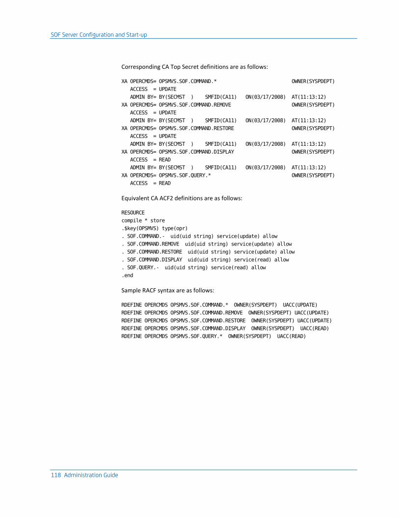
SOF Server Configuration and Start-up
118 Administration Guide
Corresponding CA Top Secret definitions are as follows:
XA OPERCMDS= OPSMVS.SOF.COMMAND.* OWNER(SYSPDEPT)
ACCESS = UPDATE
ADMIN BY= BY(SECMST ) SMFID(CA11) ON(03/17/2008) AT(11:13:12)
XA OPERCMDS= OPSMVS.SOF.COMMAND.REMOVE OWNER(SYSPDEPT)
ACCESS = UPDATE
ADMIN BY= BY(SECMST ) SMFID(CA11) ON(03/17/2008) AT(11:13:12)
XA OPERCMDS= OPSMVS.SOF.COMMAND.RESTORE OWNER(SYSPDEPT)
ACCESS = UPDATE
ADMIN BY= BY(SECMST ) SMFID(CA11) ON(03/17/2008) AT(11:13:12)
XA OPERCMDS= OPSMVS.SOF.COMMAND.DISPLAY OWNER(SYSPDEPT)
ACCESS = READ
ADMIN BY= BY(SECMST ) SMFID(CA11) ON(03/17/2008) AT(11:13:12)
XA OPERCMDS= OPSMVS.SOF.QUERY.* OWNER(SYSPDEPT)
ACCESS = READ
Equivalent CA ACF2 definitions are as follows:
RESOURCE
compile * store
.$key(OPSMVS) type(opr)
. SOF.COMMAND.- uid(uid string) service(update) allow
. SOF.COMMAND.REMOVE uid(uid string) service(update) allow
. SOF.COMMAND.RESTORE uid(uid string) service(update) allow
. SOF.COMMAND.DISPLAY uid(uid string) service(read) allow
. SOF.QUERY.- uid(uid string) service(read) allow
.end
Sample RACF syntax are as follows:
RDEFINE OPERCMDS OPSMVS.SOF.COMMAND.* OWNER(SYSPDEPT) UACC(UPDATE)
RDEFINE OPERCMDS OPSMVS.SOF.COMMAND.REMOVE OWNER(SYSPDEPT) UACC(UPDATE)
RDEFINE OPERCMDS OPSMVS.SOF.COMMAND.RESTORE OWNER(SYSPDEPT) UACC(UPDATE)
RDEFINE OPERCMDS OPSMVS.SOF.COMMAND.DISPLAY OWNER(SYSPDEPT) UACC(READ)
RDEFINE OPERCMDS OPSMVS.SOF.QUERY.* OWNER(SYSPDEPT) UACC(READ)

SOF Command Interface
Chapter 9: Switch Operations Facility 119
SOF Command Interface
This section describes the available SOF server commands.
SOF server commands can be issued as follows:
■ From a console, issue z/OS MODIFY console commands for the job name of the SOF server.
■ From OPSVIEW option 3.5.6, issue commands to an SOF server running on any CCI-connected z/OS image.
■ From a user-written OPS/REXX program using the OPS/REXX ADDRESS SOF host environment command, issue commands to an SOF server running on any CCI-connected z/OS image.
Example: Stop the SOF Server
The following z/OS MODIFY command stops the SOF server running as job named OPSOFSRV on the local z/OS system:
F OPSOFSRV,STOP
For more information on the OPS/REXX ADDRESS SOF host environment command, see the Command and Function Reference.
For a full description of OPSVIEW option 3.5.6, see the OPSVIEW User Guide.
Hardware Devices
The term hardware device is used generically for the remainder of this chapter to refer to almost any hardware device, including control units, CHPIDs, and switches, but not ports.

SOF Command Interface
120 Administration Guide
Hardware Device IDs
SOF converts the 32-byte NED of each discovered hardware device into a 28-byte hardware device ID, more simply referred to as the device ID or DEVID. The DEVID is used by SOF to correlate devices among the multiple z/OS systems in the SOF complex.
The 28-byte DEVID is included in GLOBAL SOF displays as 35 printable characters, formatted as follows:
■ Replaces non-printable characters with the character zero
■ Inserts a period between the individual fields (type, model number, manufacturer, location, serial number, and tag)
■ Converts the 2-byte binary tag to 4 printable hex characters
Example: DEVID in a GLOBAL SOF Display
The following is a typical DEVID as it would appear in a GLOBAL SOF display:
002105.000.EMC.06.300000020720.0023
For devices that are genned but do not physically exist, and older devices that do not support a NED, SOF creates an artificial DEVID, which has the following format when displayed:
@ttttt.---.---.--.NOCDR-------.nnnn
ttttt
Abbreviated device type examples: CTC, 3277, 3390, 3490, and so on
nnnn
Unique serial number assigned by SOF
Note: The first byte of an artificial DEVID is actually x'FF', but is displayed by SOF server and OPSVIEW option 3.5 as the printable character '@'.
Relative Global Device Numbers
SOF assigns each discovered hardware device a sequential six-digit hexadecimal relative global device number. Think of the relative global device number as a shorthand version of the DEVID, but they bear no relation to each other. The relative global device number is included in GLOBAL SOF command displays, and may be used to specify a device on GLOBAL SOF commands (with leading zeros not required).
Note: Assigned relative global device numbers are not static. They are dynamically reassigned whenever devices are dynamically added to or removed from the shared I/O configuration.

SOF Command Interface
Chapter 9: Switch Operations Facility 121
Specify Device Numbers
Specify a hardware device on an SOF command as one of the following:
■ A hexadecimal local z/OS device number, optionally suffixed with a period followed by the CCI system name, SMFID, or LPAR name of the owning system.
Examples: 1A, 2B.SYSA
■ The hexadecimal SOF relative global device number, optionally suffixed with a period followed by an asterisk.
Examples: 1A, 2B.*
If not suffixed, the common SOF command parameters LOCAL, GLOBAL, and SYSTEM control how a device number is interpreted.
In all cases, a device number is automatically padded on the left with zeros if less than the expected number of digits is specified. The expected number of digits for a local z/OS device number is listed for each SOF command parameter.
Assign Names to Switches and Ports
Switches and ports may be assigned a descriptive 24-character device name using the SOF command WRITENAME. Names assigned to switches are stored in the SOF checkpoint data set. Names assigned to ports are stored in the switch itself. Port names that have been assigned using a mechanism other than SOF (such as an ESCON director shared console) and saved in a switch are used and can be modified by SOF.
Use the full name assigned to a specific switch or port to specify a switch or a port on any command.
You can also use a generic name template containing the following wildcard characters anywhere in the template:
■ '*' to match one or more characters in a name.
■ '?' to match a single character in a name.
Examples: Generic Name Template with Wildcards
■ Template NAME* matches names NAMEX and NAMEXZ and NAMEXYZ.
■ Template NAME? matches names NAMEX but not NAMEXZ or NAMEXYZ.
■ Template NAME?Z matches names NAMEXZ but not NAMEX or NAMEXYZ.
■ Template NAME*Z matches names NAMEXZ and NAMEXYZ but not NAMEX.
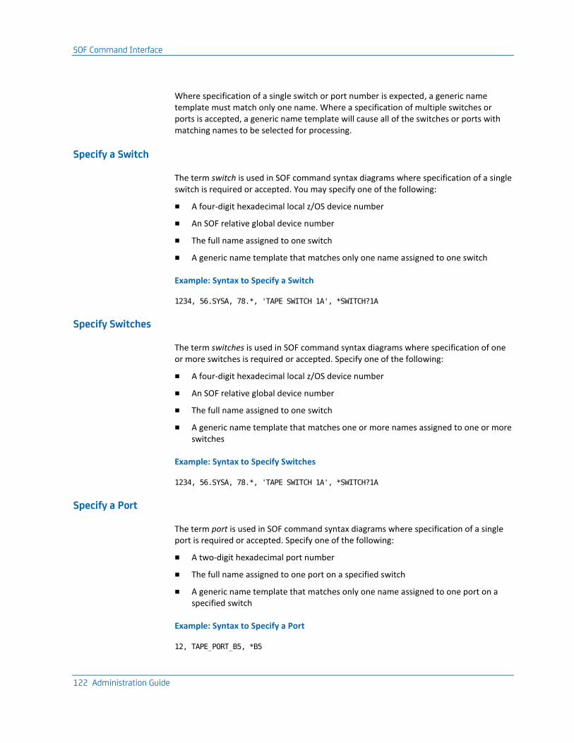
SOF Command Interface
122 Administration Guide
Where specification of a single switch or port number is expected, a generic name template must match only one name. Where a specification of multiple switches or ports is accepted, a generic name template will cause all of the switches or ports with matching names to be selected for processing.
Specify a Switch
The term switch is used in SOF command syntax diagrams where specification of a single switch is required or accepted. You may specify one of the following:
■ A four-digit hexadecimal local z/OS device number
■ An SOF relative global device number
■ The full name assigned to one switch
■ A generic name template that matches only one name assigned to one switch
Example: Syntax to Specify a Switch
1234, 56.SYSA, 78.*, 'TAPE SWITCH 1A', *SWITCH?1A
Specify Switches
The term switches is used in SOF command syntax diagrams where specification of one or more switches is required or accepted. Specify one of the following:
■ A four-digit hexadecimal local z/OS device number
■ An SOF relative global device number
■ The full name assigned to one switch
■ A generic name template that matches one or more names assigned to one or more switches
Example: Syntax to Specify Switches
1234, 56.SYSA, 78.*, 'TAPE SWITCH 1A', *SWITCH?1A
Specify a Port
The term port is used in SOF command syntax diagrams where specification of a single port is required or accepted. Specify one of the following:
■ A two-digit hexadecimal port number
■ The full name assigned to one port on a specified switch
■ A generic name template that matches only one name assigned to one port on a specified switch
Example: Syntax to Specify a Port
12, TAPE_PORT_B5, *B5

SOF Command Interface
Chapter 9: Switch Operations Facility 123
Specify a Portlist
The term portlist is used in SOF command syntax diagrams where specification of one or more ports is required or accepted. Specify any of the following, enclosing multiple specifications in parenthesis:
■ A two-digit hexadecimal port number
■ A range of ports, with start port number and end port number separated by a dash
■ A full name assigned to one port on a specified switch
■ A generic name template that matches one or more names assigned to one or more ports on a specified switch
Example: Syntax to Specify Ports
12, TAPE_PORT_B5, *B5, 20-30, (12 *B5 20-30)
Abbreviation of Commands and Parameters
Most SOF commands and parameters may be abbreviated. In the SOF command syntax diagrams, the minimum acceptable abbreviation for each command and parameter is indicated by upper case, with the remaining optional portion of the command or parameter indicated by lower case.
Example: ALLOW Command Abbreviation
The command ALLOW is described as ALLow and may be abbreviated as ALLO or minimally as ALL; an abbreviation of A or AL would generate a syntax error.
Command Syntax Format
In the SOF command syntax diagrams, optional command parameters and values are enclosed in brackets, [and], and mutually exclusive command parameters and values are delimited by a bar, |.

SOF Command Interface
124 Administration Guide
Set Common Parameter Defaults
The DEFAULTS command sets default values for common SOF command parameters. Each parameter that may be specified on the DEFAULTS command may also be specified on any other SOF command.
When processing an SOF command, the value of a common parameter specified on the command itself is used. Otherwise, the value specified on the last DEFAULTS command is used. For values never specified on any DEFAULTS command, the default values are indicated in the description of each common parameter.
Each common parameter is described in the DEFAULTS command description only. In all other command descriptions, those common parameters which are meaningful to the operation of that command are listed, but not described. Common parameters that are not meaningful to the operation of a command may be specified on the command, but are ignored after their syntax is validated. When specified, common parameters normally should be placed after all command-specific parameters.
For example, suppose the following command was issued:
DEFAULTS NOEXEC
Then the operation of the following two commands would be identical:
BLOCK 0001 01
BLOCK 0001 01 NOEXEC
And the operation of the following command would override the DEFAULTS setting:
BLOCK 0001 01 EXEC
Note: For a description of each common parameter, see subsection Miscellaneous Commands in section SOF server Commands.
Other Common Parameters
Other common parameters described here have no default value. You can specify these common parameters on any SOF command. They are described here only. In the command descriptions that follow, those common parameters which are meaningful to the operation of that command are listed, but not described. Common parameters which are not meaningful to the operation of a command may be specified on the command, but are ignored after their syntax is validated. When specified, common parameters normally should be placed after all command-specific parameters.
These common parameters are all keyword parameters that must be specified using the following format:
parameter=value

SOF Command Interface
Chapter 9: Switch Operations Facility 125
DEVID and ID Parameters
When used in conjunction with the GLOBAL parameter on DISPLAY commands, these parameters filter the returned output. Output is returned only for hardware devices whose formatted DEVID matches the specified value. The specified value may be a full DEVID, or generic DEVID template containing the following wildcard characters anywhere in the template:
■ * to match one or more characters in a DEVID.
■ ? to match a single character in a DEVID.
Specification of this parameter causes DISPLAY commands to return data in the GLOBAL format.
Minimal Abbreviation: DEV
Example: DISPLAY DEVID
To display control units manufactured by IBM only, issue command:
DISPLAY CU DEVID=*IBM*
SYSTEM Parameter
The SYSTEM parameter controls how a hardware device number specified on the command is interpreted. Specify a CCI system name, SMFID, or LPAR name to cause the command to interpret a specified hardware device number as a z/OS device number on the specified z/OS system.
Minimal Abbreviation: SYS
Example: DISPLAY SYSTEM
To display the first sixteen switches on the z/OS system with an SMFID of SYSA, issue command:
DISPLAY SWITCH COUNT=16 SYSTEM=SYSA

SOF Server Commands
126 Administration Guide
VOLUME and VOLSER Parameters
For hardware devices that may have a volume mounted on them (tape and DASD devices), these parameters filter the output returned by a DISPLAY DEVICE command. Output is returned only for hardware devices whose mounted volume serial number (VOLSER) matches the specified value. The specified value may be a full VOLSER, or generic VOLSER template containing the following wildcard characters anywhere in the template:
■ * to match one or more characters in a VOLSER.
■ ? to match a single character in a VOLSER.
Minimal Abbreviation: VOL
Example: DISPLAY VOLSER
The following command displays only devices with mounted volume serial numbers containing the string TSO:
DISPLAY DEVICE VOLSER=*TSO*
SWITCH Parameter
This parameter filters the output returned by a DISPLAY DEVICE command. Output is returned only for hardware devices connected through the specified switch.
Minimal Abbreviation: SWI
Example: DISPLAY SWITCH
To display only devices connected through switch numbered 0100 on system SYSA, issue command:
DISPLAY DEVICE SWITCH=0100.SYSA
SOF Server Commands
This section lists all the SOF server commands. They are categorized into the following command types:
■ Connectivity control commands
■ Display commands
■ Miscellaneous Commands

SOF Server Commands
Chapter 9: Switch Operations Facility 127
Connectivity Control Commands
The connectivity control commands control the status of ports and switches, and device paths connected to them.
Commands that enable new port connections imply that SOF execute z/OS VARY ONLINE operations for any offline channel path connected to affected ports, and any offline device along each channel path.
Commands that disable existing port connections imply that SOF execute z/OS VARY OFFLINE operations for any online channel path connected to affected ports, and any online device whose last channel path is taken offline.
SOF does not issue actual z/OS VARY console commands, but instead uses programmable interfaces to perform VARY operations. The full command response from each SOF command will include the equivalent z/OS VARY command text (by system) for any VARY operations attempted as part of the command, and the success or failure of the command.
Because of required cross-system communications and the asynchronous nature of VARY processing, each immediate SOF command response may not be the full command response. Therefore, SOF keeps a historical list of processed commands, their status, and their response. SOF will asynchronously update each command response as each VARY operation is executed. Each SOF command is assigned an arbitrary request ID that is returned with the immediate command response and which can be specified on the DISPLAY RESULTS command to recall the (possibly updated) command response at a later time.

SOF Server Commands
128 Administration Guide
Limit the Operation of Connectivity Control Commands
In some cases, you may only want to see what VARY operations an SOF command would perform, without actually executing the operations. For that purpose, SOF connectivity control commands support the NOEXEC parameter, which prohibits execution of all operations.
SOF connectivity control commands also support the following parameters to control or limit specific aspects of their operation:
■ NOVARY parameter, which prevents all VARY ONLINE processing for both paths and devices.
■ BACKOUT parameter, which reverses all VARY processing in case of failure.
■ FORCE parameter, which ignores any VARY failures.
■ TIMEOUT parameter, which limits the amount of time allowed for the command to fully complete execution.
■ MAXDEVICES parameter, which limits the number of devices that may be affected by the command.
■ NOVARYDEV parameter, which prevents all VARY ONLINE processing for devices only.
Note: For detailed descriptions of these parameters, see the DEFAULTS command.
ACTIVATE Command—Sets Connection Status
The ACTIVATE command sets the connectivity status of each port on the specified switch to match the saved configuration found in the specified file, and then synchronize the device path status with the new settings of the switch.
This command has the following syntax:
ACTivate switch filename
[VARy | NOVary] [VARYDev | NOVARYDev]
[EXEc| NOExec] [GLObal | LOCal] [SYStem=sysspec]
switch
Specifies the switch for which port settings are to be updated.
filename
Specifies the name of the file containing the saved switch configuration.

SOF Server Commands
Chapter 9: Switch Operations Facility 129
ALLOW Command—Allows Data Transfer
The ALLOW command allows data transfer between one port and other specified ports on the same switch by modifying dynamic connections. The reciprocal command is PROHIBIT.
This command has the following syntax:
ALLow switch portlist port
[ALSo | ONly]
[VARy | NOVary]
[FORce | NOForce]
[BACkout | NOBackout]
[VARYDev | NOVARYDev]
[EXEc| NOExec] [TIMeout=nn] [GLObal | LOCal] [SYStem=sysspec] [MAXDevices=nn]
switch
Specifies the switch for which port connections are to be modified.
portlist
Specifies the ports to be allowed data transfer with the port specified by port.
port
Specifies the port to be allowed data transfer with the ports specified by portlist.
BLOCK Command—Prohibits Data Transfer
The BLOCK command prohibits all data transfer through one port on one switch. The reciprocal command is UNBLOCK.
This command has the following syntax:
BLock switch port
[VARy | NOVary]
[FORce | NOForce]
[BACkout | NOBackout]
[VARYDev | NOVARYDev]
[EXEc | NOExec] [TIMeout=nn] [GLObal | LOCal] [SYStem=sysspec]
[MAXDevices=nn]
switch
Specifies the switch for which port connections are to be modified.
port
Specifies the port through which all data transfer is to be prohibited.

SOF Server Commands
130 Administration Guide
CONNECT Command—Establishes a Connection
The CONNECT command establishes a static, or dedicated, connection between two ports on the same switch. The reciprocal command is DISCONNECT.
This command has the following syntax:
CONnect switch port1 port2
[VARy | NOVary]
[FORce | NOForce]
[BACkout | NOBackout]
[VARYDev | NOVARYDev]
[EXEc| NOExec] [TIMeout=nn] [GLObal | LOCal] [SYStem=sysspec] [MAXDevices=nn]
switch
Specifies the switch for which port connections are to be modified.
port1
Specifies the port for which a dedicated connection is to be established with the port specified by port2.
port2
Specifies the port for which a dedicated connection is to be established with the port specified by port1.
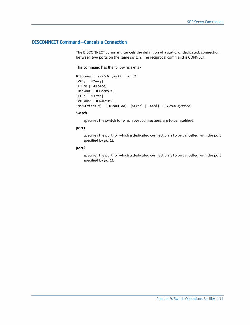
SOF Server Commands
Chapter 9: Switch Operations Facility 131
DISCONNECT Command—Cancels a Connection
The DISCONNECT command cancels the definition of a static, or dedicated, connection between two ports on the same switch. The reciprocal command is CONNECT.
This command has the following syntax:
DISConnect switch port1 port2
[VARy | NOVary]
[FORce | NOForce]
[Backout | NOBackout]
[EXEc | NOExec]
[VARYDev | NOVARYDev]
[MAXDEVices=n] [TIMeout=nn] [GLObal | LOCal] [SYStem=sysspec]
switch
Specifies the switch for which port connections are to be modified.
port1
Specifies the port for which a dedicated connection is to be cancelled with the port specified by port2.
port2
Specifies the port for which a dedicated connection is to be cancelled with the port specified by port1.

SOF Server Commands
132 Administration Guide
PROHIBIT Command—Prohibits Data Transfer
The PROHIBIT command prohibits data transfer between one port and other specified ports on the same switch by modifying dynamic connections. The reciprocal command is ALLOW.
This command has the following syntax:
PROhibit switch portlist port
[ALSo | ONly]
[VARy | NOVary]
[EXEc | NOExec]
[FORce | NOForce]
[BACkout | NOBackout]
[VARYDev | NOVARYDev]
[MAXDevices=nn] [TIMEout=nn] [GLObal | LOCal] [SYStem=sysspec]
switch
Specifies the switch for which port connections are to be modified.
portlist
Specifies the ports to be prohibited data transfer with the port specified by port.
port
Specifies the port to be prohibited data transfer with the ports specified by portlist.
REMOVE Command—Closes a Switch
Use the REMOVE command to close and unallocate a switch. This allows the switch to be taken offline, or to be used by another system component. Existing port connectivity is not affected.
This command has the following syntax:
REMove switch
[GLObal | LOCal] [SYStem=sysspec]
switch
Specifies the switch to be closed and unallocated.

SOF Server Commands
Chapter 9: Switch Operations Facility 133
RESET SWITCH Command—Updates SOF
Use the RESET SWITCH command to update the SOF environment for a single switch, without updating device path status to match the switch settings.
Note: Use the SYNCH SWITCH instead if you want to update the device path status to match the switch settings.
This command has the following syntax:
RESET SWitch switch
[GLObal | LOCal] [SYStem=sysspec]
switch
Specifies the switch for which the SOF environment is to be updated.
RESTORE Command—Opens a Switch
Use the RESTORE command to allocate and open a switch.
This command has the following syntax:
RESTore switch
[GLObal | LOCal] [SYStem=sysspec]
switch
Specifies the switch to be allocated and opened.
SYNCH Command—Synchronizes Device Path Status
The SYNCH command updates the SOF environment for the specified switch, and then synchronizes the device path status with the current settings of the switch.
Note: Use the RESET SWITCH command instead if you do not wish to update the device path status to match the switch settings.
This command has the following syntax:
SYNCh switch
[EXEc| NOExec] [GLObal | LOCal] [SYStem=sysspec]
switch
Specifies the switch for which the SOF environment is to be updated.

SOF Server Commands
134 Administration Guide
UNBLOCK Command—Allows Data Transfer
The UNBLOCK command allows all data transfer through one port on one switch. The reciprocal command is BLOCK.
This command has the following syntax:
UNBlock switch port
[VARy | NOVary]
[FORce | NOForce]
[VARYDev | NOVARYDev]
[BACkout | NOBackout] [TIMeout=nn] [MAXDevices=nn]
[GLObal | LOCal] [SYStem=sysspec] [EXEc | NOExec]
switch
Specifies the switch for which port connections are to be modified.
port
Specifies the port through which all data transfer is to be allowed.
Display Commands
The display commands return information about SOF servers and hardware devices in the shared I/O configuration.
The DISPLAY CHPID, DISPLAY CU, DISPLAY DEVICE, and DISPLAY SWITCH command displays have two formats, with different content, controlled by the specification of the hardware device and the DEVID common parameter:
■ LOCAL format
If a local z/OS device number is specified without the DEVID common parameter being specified, the LOCAL format of the display is returned.
■ GLOBAL format
If an SOF relative global device number or descriptive name is specified, or if the DEVID common parameter is specified, the GLOBAL format of the display is returned.

SOF Server Commands
Chapter 9: Switch Operations Facility 135
DISPLAY Command—Displays SOF Server Information
The DISPLAY command displays information about the SOF server environment.
This command has the following syntax:
Display [ALL][DEFaults]
[OPTions]
[STATistics]
[STORage]
[MAXLines=nn]
ALL
(Optional) Displays all available information.
DEFaults
(Optional) Displays current values for all common and default parameters.
For a description of the display, see message OPS5650I.
OPTions
(Optional) Displays SOF operating parameters.
For a description of the display, see message OPS5715I.
STATistics
(Optional) Displays statistics counters.
For a description of the display, see message OPS5655I.
STORage
(Optional) Displays storage utilization statistics.
For a description of the display, see message OPS5690I.

SOF Server Commands
136 Administration Guide
DISPLAY CHPID Command—Displays CHPID Information
The DISPLAY CHPID command displays information about one or more managed channel paths.
For a description of the display, see message OPS5680I. For a description of the display, see message OPS5750I.
This command has the following syntax:
Display CHPid [chpspec] [MAXLines=nn] [Count=nn] [DETail=level]
[GLObal | LOCal] [SYStem=sysspec] [DEVid|ID=string]
chpspec
(Optional) Specifies the channel paths to be displayed. This may be a single CHPID, a range of CHPIDs, a list of CHPIDs, or a combination of both. Each CHPID is a one- or two-digit hexadecimal number.
If not specified, information is shown about each managed channel path.
DISPLAY CU Command—Displays Control Unit Information
The DISPLAY CU command displays information about one or more managed control units. For a description of the local display, see message OPS5730I. For a description of the global display, see message OPS5720I.
This command has the following syntax:
Display CU [cuspec] [MAXLines=nn] [Count=nn] [DETail=level]
[GLObal | LOCal] [SYStem=sysspec] [DEVid|ID=string]
cuspec
(Optional) Specifies the first control unit for which information is to be displayed. The expected number of hexadecimal digits for a local z/OS control unit number is two. If not specified, information is shown about each managed control unit.

SOF Server Commands
Chapter 9: Switch Operations Facility 137
DISPLAY DEVICE Command—Displays Managed Device Information
The DISPLAY DEVICE command displays information about one or more managed devices. For a description of the local format of the display, see message OPS5670I For a description of the global format of the display, see message OPS5740I.
This command has the following syntax:
Display Device [devspec] [SWItch=switch] [Count=nn]
[DETail=level] [MAXLines=nn]
[GLObal | LOCal] [SYStem=sysspec] [DEVid|ID=string]
devspec
(Optional) Specifies the first device for which information is to be displayed. The expected number of hexadecimal digits for a local z/OS device number is four. If not specified, information is shown about each managed device.
Examples: Display Device Information
■ This command displays information about only the device numbered 0B0 on the local host:
Dis Dev 0B0 Local
■ This command displays information about all devices in the shared I/O configuration:
Dis Dev Global
■ This command displays information about 10 devices on the local host, starting with the device numbered C00 on the local host:
Dis Dev c00 C=10 Local
■ This command displays information about devices connected to the switch numbered 004 on host ABC:
Dis Dev SW=004.ABC
DISPLAY RESULTS Command—Displays SOF Connect Results
The DISPLAY RESULTS command displays the results of a recent SOF connectivity command. For a description of the display, see message OPS5700I.
This command has the following syntax:
Display RESults [reqid] [MAXLines=nn]
reqid
(Optional) Specifies the request ID associated with the command response to be displayed. An associated request ID is returned in each SOF connectivity command response.
If not specified, a status summary for all recent connectivity commands is shown.
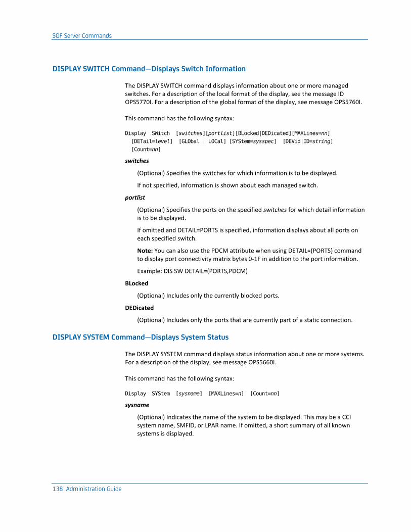
SOF Server Commands
138 Administration Guide
DISPLAY SWITCH Command—Displays Switch Information
The DISPLAY SWITCH command displays information about one or more managed switches. For a description of the local format of the display, see the message ID OPS5770I. For a description of the global format of the display, see message OPS5760I.
This command has the following syntax:
Display SWitch [switches][portlist][BLocked|DEDicated][MAXLines=nn]
[DETail=level] [GLObal | LOCal] [SYStem=sysspec] [DEVid|ID=string]
[Count=nn]
switches
(Optional) Specifies the switches for which information is to be displayed.
If not specified, information is shown about each managed switch.
portlist
(Optional) Specifies the ports on the specified switches for which detail information is to be displayed.
If omitted and DETAIL=PORTS is specified, information displays about all ports on each specified switch.
Note: You can also use the PDCM attribute when using DETAIL=(PORTS) command to display port connectivity matrix bytes 0-1F in addition to the port information.
Example: DIS SW DETAIL=(PORTS,PDCM)
BLocked
(Optional) Includes only the currently blocked ports.
DEDicated
(Optional) Includes only the ports that are currently part of a static connection.
DISPLAY SYSTEM Command—Displays System Status
The DISPLAY SYSTEM command displays status information about one or more systems. For a description of the display, see message OPS5660I.
This command has the following syntax:
Display SYStem [sysname] [MAXLines=n] [Count=nn]
sysname
(Optional) Indicates the name of the system to be displayed. This may be a CCI system name, SMFID, or LPAR name. If omitted, a short summary of all known systems is displayed.

SOF Server Commands
Chapter 9: Switch Operations Facility 139
Miscellaneous Commands
The miscellaneous commands control the operation of SOF.
ALLOCATE Command—Allocates a Data Set
The ALLOCATE command dynamically allocates a data set to the SOF server started task.
This command has the following syntax:
ALLOCate DDName=ddn
[DSName=dsn | PATH=pathname | SYSOut=sysclass]
[DISP={SHR|OLD|MOD}]
ddn
Specifies the ddname of the data set to be allocated; this is required.
dsn
Specifies the name of a normal z/OS data set to be allocated.
pathname
Specifies the name of an HFS or zFS in compatibility mode data set to be allocated; may be an absolute pathname, or relative to the home directory for the user ID used by the SOF server task.
sysclass
Specifies the class of a spool data set to be allocated.
DISP
Specifies the normal disposition for the data set to be allocated.
Default: SHR
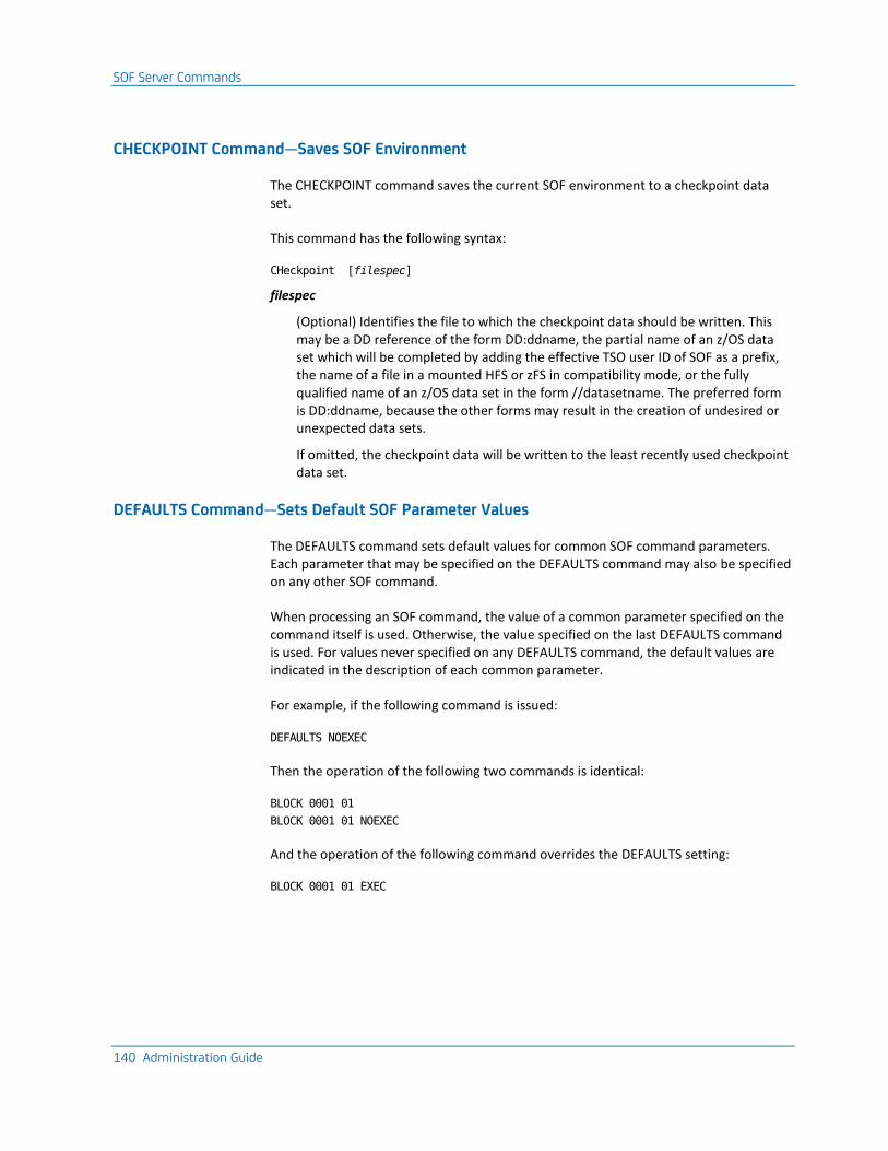
SOF Server Commands
140 Administration Guide
CHECKPOINT Command—Saves SOF Environment
The CHECKPOINT command saves the current SOF environment to a checkpoint data set.
This command has the following syntax:
CHeckpoint [filespec]
filespec
(Optional) Identifies the file to which the checkpoint data should be written. This may be a DD reference of the form DD:ddname, the partial name of an z/OS data set which will be completed by adding the effective TSO user ID of SOF as a prefix, the name of a file in a mounted HFS or zFS in compatibility mode, or the fully qualified name of an z/OS data set in the form //datasetname. The preferred form is DD:ddname, because the other forms may result in the creation of undesired or unexpected data sets.
If omitted, the checkpoint data will be written to the least recently used checkpoint data set.
DEFAULTS Command—Sets Default SOF Parameter Values
The DEFAULTS command sets default values for common SOF command parameters. Each parameter that may be specified on the DEFAULTS command may also be specified on any other SOF command.
When processing an SOF command, the value of a common parameter specified on the command itself is used. Otherwise, the value specified on the last DEFAULTS command is used. For values never specified on any DEFAULTS command, the default values are indicated in the description of each common parameter.
For example, if the following command is issued:
DEFAULTS NOEXEC
Then the operation of the following two commands is identical:
BLOCK 0001 01
BLOCK 0001 01 NOEXEC
And the operation of the following command overrides the DEFAULTS setting:
BLOCK 0001 01 EXEC

SOF Server Commands
Chapter 9: Switch Operations Facility 141
Note: Each common parameter is described here in the DEFAULTS command description only. In all other command descriptions, those common parameters which are meaningful to the operation of that command are listed, but not described. Common parameters that are not meaningful to the operation of a command may be specified on the command, but are ignored after their syntax is validated. When specified, common parameters normally should be placed after all command-specific parameters.
This command has the following syntax:
DEFaults
/* The following are common parameters: */
[ALSo|ONLy]
[BACkout|NOBackout]
[COUnt=nn]
[DETail=level]
[EXEc|NOExec]
[FORce|NOForce]
[GLObal|LOCal]
[MAXDevices=nn]
[MAXLines=nn]
[TIMeout=nn]
[VARy|NOVary]
The following parameters are meaningful only to SOF connectivity control commands.
ALSo and ONLy
These parameters control how the ALLOW and PROHIBIT commands affect dynamic switch connectivity. Specify ONLY to allow or prohibit only the dynamic connections specified on the command. Specify ALSO to allow or prohibit the dynamic connections specified on the command in addition to those that are already allowed or prohibited.
Default: ALSO
BACkout and NOBackout
These parameters control attempted recovery from implied z/OS VARY operations when the command fails.
Specify BACKOUT to instruct SOF to attempt recovery in the case of command failure. SOF will attempt to restore the online or offline status of any channel path or device that was altered by implied z/OS VARY operations.
Specify NOBACKOUT to instruct SOF to not attempt recovery in the case of command failure.
Default: BACKOUT

SOF Server Commands
142 Administration Guide
EXEc and NOExec
These parameters control the execution of the command. Specify EXEC to cause the command to be fully executed, and if successful, to update switch connectivity. Specify NOEXEC to prevent the command from being fully executed and updating switch connectivity.
Regardless of which parameter is specified, the full response to the command will include the equivalent z/OS VARY command text (by system) for any implied z/OS VARY operations. Thus, the NOEXEC parameter is useful for determining what implied z/OS VARY operations would be executed by the command if it were to be fully executed.
Default: NOEXEC
FORce and NOForce
The FORCE parameter causes SOF to ignore VARY failures. When NOFORCE is in effect, SOF will abort an operation if any VARY OFFLINE fails for a path or device.
Default: NOFORCE
MAXDevices=nn
This parameter limits the number of devices that are affected by the command. If full execution of the command to affects more than the specified number of devices, the command is not fully executed and proceeds as if the NOEXEC parameter were specified.
Default value: 256
TIMeout=nn
This parameter limits the amount of time allowed, in seconds, to complete execution of the command. If the specified number of seconds expires before the command has completed execution, the command fails.
Default value: 60
VARy and NOVary
These parameters control the execution of implied z/OS VARY ONLINE operations by the command. Specifying VARY causes the command to execute any implied z/OS VARY ONLINE operations. Specifying NOVARY prevents the command from executing any implied z/OS VARY ONLINE operations.
Note: VARY ONLINE processing is affected by the VARYCLASS parameter of the SET command.
Regardless of which parameter is specified, the full response to the command will include the equivalent z/OS VARY command text (by system) for any implied z/OS VARY operations.
Default: VARY

SOF Server Commands
Chapter 9: Switch Operations Facility 143
The following parameters are meaningful only to SOF display commands.
COUnt=nn
Limits the number of objects returned in the command display.
Default value: 16
DETail=level
Controls the amount of information returned for each object in the command display. The level specified may be any combination of the following values, enclose in parenthesis if specifying more than one value:
DEVices
Returns devices attached to each object
CHPids
Returns CHPIDs attached to each object
CUs
Returns control units attached to each object
SYStems
Returns systems attached to each object
SWItches
Returns switches attached to each object
PATH
Returns path information for devices
PORts
Returns ports attached to each object
ID|DEVID
Returns the DEVID of each object
ALL
Returns all of the above information
NONE
Returns none of the above information
Most display commands support only a subset of these values. For any display command, non-supported values are ignored.
Default: NONE
MAXLines=nn
Limits the number of lines returned to an MCS console or extended console.

SOF Server Commands
144 Administration Guide
Specify the MAXLines=nn keyword on any SOF command using the z/OS MODIFY command. Commands issued from the SOF ISPF panels, either from option 6, or the CMD primary command, are not affected.
Default value: 100
Note: Regardless of the specified value, the full command display is always written to the SOF LOG.
The following parameters are meaningful to both SOF connectivity control and display commands.
GLObal and LOCal
These parameters control how a hardware device number specified on the command is interpreted. Specify LOCAL to cause the command to interpret a specified hardware device number as a z/OS device number on the local z/OS system on which the command is executed. Specify GLOBAL to cause the command to interpret a specified hardware device number as an SOF relative global device number.
These parameters also control the content and format of the DISPLAY CHPID, DISPLAY CU, DISPLAY DEVICE, and DISPLAY SWITCH command displays.
Default: LOCAL

SOF Server Commands
Chapter 9: Switch Operations Facility 145
DEFINE SWITCH Command—Identifies a Switch
The DEFINE SWITCH command is used in the INITCMDS file to identify a switch to the SOF server. This command is not normally needed. For information about situations in which this command is needed, see Define Switches (see page 114).
This command has the following syntax:
DEFINE SWItch devnum devid [name] [LSN=lsn]
devnum
Provides the logical device number of the switch as specified in the IODF of the local system. If this number is different on different systems in the SOF complex, then a different DEFINE SWITCH command is directed to each different system.
devid
An arbitrary DEVID that SOF uses to properly correlate the switch among the multiple z/OS systems in the SOF complex. This value should be the same on each DEFINE SWITCH command that is issued for the same switch-on different systems. Specify the 28-byte DEVID as 35 printable characters, with a period between the individual fields. The individual fields are type, model number, manufacturer, location, serial number, and tag. Specify the 2-byte binary tag as four printable hex characters.
Example: 009032.005.IBM.02.FAKESERIAL03.0000
name
(Optional) The name to be assigned to the defined switch. The name can be up to 24 characters in length, and can contain the following special characters: space, digits, period, and underscore. Delimit a name that contains spaces using quotes.
lsn
(Optional). The logical switch number for the switch. The value must be two-hex digits, in the range 00-FF. Normally, SOF can determine the logical switch number automatically. The LSN keyword is needed only when the I/O device number for the switch does not match the logical switch number.

SOF Server Commands
146 Administration Guide
DEFINE SYSTEM Command—Defines a System
The DEFINE SYSTEM command defines a system or host. Although SOF will automatically discover all active SOF servers, by predefining the expected peer systems, SOF will recognize when the external systems have either not been started, or have been shut down.
This command has the following syntax:
DEFINE SYStem sysname [RESET]
sysname
Specifies the CCI system name of the system being defined.
RESET
(Optional) Treats the system as if the RESET SYSTEM command has been issued.
Note: This has no effect at restart from a checkpoint for a system found in the checkpoint; for such a system, the status found in the checkpoint is used.
FREE Command—Unallocates a Data Set
The FREE command dynamically unallocates a data set from the SOF started task.
This command has the following syntax:
FREE ddname
ddname
Specifies the name of the DD to be freed.
PURGE Command—Deletes Responses
The PURGE command deletes the saved response to a completed connectivity command. Use of the PURGE command is optional, since a saved command response is deleted automatically after the amount of time specified on the RESultsinterval option has elapsed.
This command has the following syntax:
PURGE reqid
reqid
Specifies the request ID assigned to the command response to be purged. The request ID is assigned when the command is first accepted. You may also get a list of outstanding requests through the DISPLAY RESULTS command.

SOF Server Commands
Chapter 9: Switch Operations Facility 147
REDISCOVER Command—Performs Full Discovery
The REDISCOVER command abandons the current I/O configuration information, and performs full discovery of the I/O configuration on the local system.
This command has the following syntax:
REDIScover
RESETALERT Command – Disables User Alerts for a Switch
The RESETALERT command disables User Alert mode for the specified switch. When a User Alert mode is enabled, the Enterprise Connectivity Server (EFC) sends a general warning indication to the EFC user. This warning is sent whenever the user attempts an action which updates the switch status or parameters. This warning is a reminder that the switch is being managed by host software, namely SOF.
This command has the following syntax:
RESETALERT switch
switch
Specifies the switch for which User Alert mode can be disabled.
RESET SYSTEM Command—Resets a System
The RESET SYSTEM command marks a failed/stopped host as inactive. This allows SOF commands to proceed without acknowledgement from the inactive host.
This command has the following syntax:
RESET SYStem hostname [PURge]
hostname
Specifies the host name to be reset. This may be a CCI system name, SMFID, or LPAR name.
PURge
(Optional) Specified by hostname, and all associated devices and switches known only to that host, to be removed from the SOF environment.

SOF Server Commands
148 Administration Guide
SET Command—Modifies Parameters
The SET command modifies the operating parameters of the SOF server.
This command has the following syntax:
SET [Autoopen={YES|NO}]
[CCIApplname=name]
CheckInterval=minutes]
[CHECKPOINTFile=list]
[CHECKPOINTInterval=seconds]
[CmdRespRemoteLog]={YES|NO}]
[enablePPRC]={YES|NO}]
[Heartbeatinterval=minutes]
[LOGFile=logspec]
[LOGLevel=level]
[Minccidelay=milliseconds]
[MSGprefix=prefix]
[Portsettletime=secs]
[PprcPrimaryDevices=deviceRange]
[PprcSecondaryDevices=deviceRange]
[RELoadcheckpoint={YES|NO}]
[RESultsinterval=minutes]
[RUnopt=opts]
[SHaredevices={YES|NO}]
[SToragesize=bytes]
[TImerinterval=secs]
[TRace=types]
[UserAlertMode={YES|NO}]
[Varyclass=varyspec]
Autoopen=YES|NO
Controls whether the SOF server automatically allocates and opens each discovered switch. Unless a switch is allocated and open, connectivity changes to the switch are not possible.
Default: YES
Note: The status of individual switches may be modified using the REMOVE and RESTORE commands.
CCIApplname=name
Specifies the CCI application name for CCI communication.
All SOF servers using the same CCI application name become members of an SOF complex and share their configuration information. Multiple SOF complexes can be run simultaneously by using a different CCI application name for each SOF complex.

SOF Server Commands
Chapter 9: Switch Operations Facility 149
Place a SET CCIAPPLNAME command in the INITCMDS file to define an SOF server to an alternate SOF complex using an alternate CCI application name. To facilitate the use of OPSVIEW option 3.5, the CCI application name should begin with OPsof. The CCI application name is not case-sensitive.
Default: OPsofServer
CHECKInterval=nn
Specifies the number of minutes between automatic checks for an external modification. Each time this interval expires, SOF queries each managed switch to determine whether any port or options have been modified externally. This modification can be either by other host software, or by a user at the Enterprise Fabric Connectivity Server console.
Default: 15
Minimum: 1
Maximum: 60
CHECKPOINTFile=list
Specifies a list of one to four file specifications for the checkpoint files. Each specification may be a ddname reference of the form DD:ddname, the name of a file within a mounted HFS or zFS in compatibility mode, or the name of a z/OS data set of the form //dsname.
Abbreviation: CKPTFile
CHECKPOINTInterval=minutes
Specifies the minimum number of minutes between automatic checkpoints.
Default: 10
Minimum: 1
Maximum: 60
CmdRespRemoteLog=YES|NO
This parameter controls whether output for commands routed to a remote SOF server is also written to the remote server log. The response is always logged in the local SOF server regardless of this option.
Default: NO

SOF Server Commands
150 Administration Guide
EnablePPRC=YES|NO
Specifies whether SOF can enable the PPRC functions.
YES
Specifies that SOF can enable the PPRC functions.
NO
Specifies that SOF cannot enable the PPRC functions.
Default: NO

SOF Server Commands
Chapter 9: Switch Operations Facility 151
Heartbeatinterval=minutes
Specifies, in minutes, the amount of time between heartbeat messages.
When SOF detects that a peer has not sent a heartbeat message within the allotted time, the system is placed into a late state. As long as any system is late, SOF will reject all connectivity commands, until the late systems send a heartbeat, or until the late system is reset through a RESET SYSTEM command.
Default: 15 minutes
LOGFile=logspec
Specifies the name for the SOF log file, which may be a ddname reference of the form DD:ddname, the name of a file within a mounted HFS or zFS in compatibility mode, the z/OS data set name of the form //dsname, or OPS:OPSLOG, which represents the OPS/MVS log.
Default: 'DD:OPIOLOG'
LOGLevel=level
Specifies the level of SOF messages written to the SOF LOG file. This excludes SOF trace messages activated by the TRACE option, which are always written. Each possible level is listed here from least to most amount of messages written. Each successive level in the list includes messages written for every prior listed level:
Fatal
Indicates fatal error messages are logged.
CRitical
Indicates critical error messages are logged.
Error
Indicates all error messages are logged.
Warning
Indicates warning messages are logged.
COmmands
Indicates input commands and responses are logged.
Normal
Indicates informational messages are logged.
Verbose
Indicates extra informational messages are logged, mostly details of discovery.
Default: Normal
Minccidelay=milliseconds

SOF Server Commands
152 Administration Guide
Specifies, in milliseconds, the minimum time between outgoing CCI messages. This is necessary on some platforms, to avoid CCI errors caused by sending messages too quickly.
Default: 0
MSGprefix=prefix
Specifies the three-byte message prefix for all SOF messages.
Default: OPS
Portsettletime=secs
Specifies, in seconds, the amount of time allotted for switch port changes to resolve before bringing dependent paths and devices online.
Default: 1
Note: If you frequently encounter message OPS5966 after port changes, increase the time.
PprcPrimaryDevices=deviceRange
Specifies, as a hexadecimal device number pair, a continuous range of DASD volumes, which then become the only allowable primary volumes in a mirror volume pair relationship. This parameter can be used while testing to ensure that production volumes are not overwritten.
Alias: PprcPDev
Default: 0000:ffff
Note: The primary and secondary volumes are reversed during a Disaster Recovery or Planned Outage situation. Therefore, CA OPS/MVS does not currently check whether volumes are primary or secondary.
PprcSecondaryDevices=deviceRange
Specifies, as a hexadecimal device number pair, a continuous range of DASD volumes, which then become the only allowable secondary volumes in a mirror volume pair relationship. This parameter can be used while testing to ensure that production volumes are not overwritten.
Alias: PprcSDev
Default: 0000:ffff
Note: The primary and secondary volumes are reversed during a Disaster Recovery or Planned Outage situation. Therefore. CA OPS/MVS does not currently check whether volumes are primary or secondary.

SOF Server Commands
Chapter 9: Switch Operations Facility 153
RELoadcheckpoint=YES|NO
Controls the use of checkpoint data at SOF restart. If YES is specified, SOF reloads the environment from the most recently written checkpoint file. If NO is specified, SOF ignores all checkpoint data. This is normally specified in the PARM field for the SOF server, not in a SOF PARM data set.
RESultsinterval=minutes
Specifies, in minutes, the amount of time to retain the connectivity command results after command completion.
Default: 15
Note: Use the PURGE command to remove the results from individual commands.

SOF Server Commands
154 Administration Guide
RUnopt=opts
Indicates opts is a string of runtime options which should be passed to all subtasks.
Default: trap(on)
SHaredevices=YES|NO
Controls whether device information is shared among the SOF servers. Specifying NO reduces the amount of virtual storage used by each of the servers, which makes some of the displays less informative.
Default: YES
SToragesize=bytes
Specifies, in kilobytes, the amount of storage to be acquired whenever additional storage is needed. Each acquired block is subdivided as needed by SOF.
Default: 1024, which is the minimum amount that may be specified.
TImerinterval=secs
Specifies, in seconds, the length of the timer used to periodically awaken time-driven SOF components.
Default: 60
Trace=types
Specifies the types of SOF generated trace messages written to the SOF LOG file. Trace messages are written to the SOF LOG file regardless of the setting of the LOGLEVEL option. Specification of any combination of the following types will turn on the described tracing:
ALL
All tracing
CCI
CCI tracing
CHECKpoint
Checkpoint read/write routine tracing
COMMands
Operator command processor tracing
CONTROLblocks
Formatted control block tracing
Abbreviation: CB
DATa
Formatted data buffer tracing
Discovery

SOF Server Commands
Chapter 9: Switch Operations Facility 155
Configuration discovery tracing
ENF
ENF processor tracing
ENTRy
Module/function entry tracing
EVENTs
Event processor tracing
EXIT
Module/function exit tracing
NONE
No tracing
RETURNcodes
Non-zero return code tracing
Abbreviation: RC
SwitchIO
Switch-related channel programs tracing
Vary
Vary online or offline tracing
Note: To turn off an individual trace type, prefix the type with NO. For example, the following command turns on all tracing except for CCI:
'Set Trace=(ALL,NOCCI)'
The following types may be specified to toggle tracing off or on while retaining all of the previously specified trace types:
OFF
Toggle tracing off while retaining all previously specified trace types.
ON
Toggle tracing on of all previously specified trace types.

SOF Server Commands
156 Administration Guide
UserAlertMode=YES|NO
Specifies whether SOF can automatically enable User Alert Mode for each switch immediately after completing configuration discovery. When User Alert mode is enabled, the Enterprise Connectivity Server (EFC) sends a general warning indication to the EFC user when the user attempts an action which updates the switch status or parameters.
Note: The message is a reminder that the switch is being managed by host software, namely SOF.
YES
Specifies that SOF can enable User Alert mode for each managed switch.
NO
Specifies that SOF cannot change the status of User Alert mode for each managed switch.
Default: NO

SOF Server Commands
Chapter 9: Switch Operations Facility 157
Varyclass=varyspc
Specifies the device classes that are eligible for VARY ONLINE processing. You can specify any combination of the following, enclosed in parentheses if more than one is specified:
None
Specifies no devices should be varied online.
ALL
Varies all devices online.
CHAR
Varies character devices online.
CTC
Varies CTC devices online.
COMM
Varies communication devices online.
DASD
Varies direct access storage devices online.
DISPLAY
Varies display devices online.
TAPE
Varies tape devices online.
UR
Varies unit record devices online.
Default: None.
Note: During VARY ONLINE processing, device paths are varied online unless the NOVARY option is in effect. Devices are varied online by SOF only if the appropriate device class is enabled. However, an API rule can selectively bring devices online by acting on the OPSOFVARYxx events.

SOF Server Commands
158 Administration Guide
SETALERT Command – Enables User Alerts for a Switch
The SETALERT command enables User Alert mode for the specified switch. When User Alert mode is enabled, the Enterprise Connectivity Server (EFC) sends a general warning indication to the EFC user. This warning is sent when the user attempts an action which updates the switch status or parameters. This warning is a reminder that the switch is being managed by host software, namely SOF.
This command has the following syntax:
SETALERT switch
switch
Specifies the switch for which User Alert mode can be enabled.
STOP Command—Terminates the Server
The STOP command terminates the SOF server.
This command has the following syntax:
STOP [GLObal RESet]
GLObal
Performs a synchronized shutdown of all SOF servers.
RESet
Specifies that all active SOF servers should be notified. Each of the servers that receive the notification will set the status of the stopping system to Down. The effect is the same as issuing the RESET SYSTEM command on one of the remaining servers. This prevents the remaining active servers from issuing the OPS5891W warning about missing heartbeats from the stopped server and allows execution of connectivity commands without acknowledgement from the stopped server.

SOF Server Commands
Chapter 9: Switch Operations Facility 159
WRITENAME Command—Assigns a Name
The WRITENAME command assigns a name to a switch, or to a port on a switch. Names assigned to ports are stored in the switch itself. Names assigned to switches are stored in the SOF checkpoint data set.
This command has the following syntax:
WRitename name switch [port]
name
Specifies the name to be assigned to the specified switch or port.
The name may be up to 24 characters in length, and may contain spaces, digits, periods, and underscores. A name that contains spaces must be delimited by quotes.
switch
If port is specified, indicates the switch containing the port to be assigned the name.
If port is not specified, indicates the switch to be assigned the name.
port
Specifies the port on the specified switch to be assigned the name.


Chapter 10: High Availability 161
Chapter 10: High Availability
This section contains the following topics:
Overview (see page 161) High Availability PPRC features (see page 162) PPRC Setup Requirements (see page 163) Working With PPRC Environment Definitions File (see page 163) Syntax of the definitions file (see page 163)
Overview
This High Availability Option provides the capability to display and configure Peer to Peer Remote Copy (PPRC) paths and mirror volumes. PPRC is a hardware solution to the problem of accurate and rapid disaster recovery, and also provides a workload migration solution. This option is designed to provide data transfer synchronously and asynchronously.
Synchronous PPRC is designed to provide real-time mirroring of logical volumes within an ESS or between two ESSs. The sites using synchronous PPRC must conform to the following conditions:
■ The recovery storage subsystem, must be current with the primary system.
■ Some level of a performance impact to an application or applications read write I/O operations at the primary location is acceptable.
■ If two ESSs are involved, they cannot be more than 103 km apart with a ESCON® connectivity, or 200 km apart with Fiber, as distances increase the performance impact worsens.

High Availability PPRC features
162 Administration Guide
How Synchronous PPRC works
The PPRC synchronous copy functions are:
■ A PPRC data copy to the recovery storage subsystem is synchronous with the I/O operation of the primary volume. This means that the primary system writes data to a volume of the primary storage subsystem. The data is then transferred to cache and nonvolatile storage (NVS), and the storage control sends channel end status to the host.
■ The primary site storage control then initiates an I/O channel program to the recovery site storage control to transfer the updated data.
■ The primary site storage control returns device end status to the primary system when the transfer to the recovery site storage control cache and NVS is complete.
■ The primary system notifies the application program that the operation is complete.
Note: The PPRC copy function does not consider the primary system DASD write operation complete until the data that is sent to the recovery storage subsystem has received channel end and device end status from the secondary volume storage control. Each primary system write to the recovery subsystem causes an increase to the primary system response time.
High Availability PPRC features ISPF Interface
OPSVIEW option 3.6 provides an ISPF user interface which provides the following functions:
■ Create, display, and delete PPRC paths connecting primary and secondary ESSs.
■ Create, display, and delete PPRC mirrored volumes pairs.
■ Save and view the current PPRC environment definitions in a flat file.
■ Offers a wizard style of creating the PPRC paths and mirrored volumes.
OPS/REXX Host Environment
The OPS/REXX ADDRESS SOF host environment has been extended with the set of PPRC related commands. These commands let users write OPS/REXX programs to issue PPRC commands directly. Command output is returned in OPS/REXX stem variables for interrogation by the calling program.
Saved PPRC Configuration
You can specify the PPRC definitions by manually editing the text flat file. This file is specified in your SOF/PPRC z/OS starting procedure, or through the OPSVIEW ISPF dialog. This flat file is updated with any changes you made to the PPRC environment through the OPSVIEW interface.

PPRC Setup Requirements
Chapter 10: High Availability 163
PPRC Setup Requirements
The High Availability PPRC feature has been developed as an extension of the Switch Operation Facility (SOF). The correct settings for the SOF server are a prerequisite for using the PPRC. Also perform the following steps:
■ Set the enablePPRC parameter to YES in your SOF configuration file that is defined by INITCMDS DD statement in OPSOFSRV z/OS starting procedure.
■ Define the location for your PPRC environment definitions file by setting the PPRC DD statement in your OPSOFSRV z/OS starting procedure.
Working With PPRC Environment Definitions File
The PPRC environment definition file stores your current PPRC environment. Upon exit from PPRC Main Menu, you are asked if you changes should be saved. View the PPRC environment content by:
■ Using the View Environment OPSVIEW panel under PPRC Main Menu.
■ Viewing directly in a dataset you specified in the PPRC DD statement of your OPSOFSRV server z/OS started task procedure.
Important! We highly recommend that you use the OPSVIEW ISPF dialogs to define your PPRC environment, instead of directly editing the definitions file.
Syntax of the definitions file
To define a PPRC path, use following syntax:
PSITE(): PRIM(ssid wwnn lss) SEC(ssid wwnn lss) LINK(X’pfca1sfca1’ X’pfca2sfca2’ …)
To define a PPRC mirror volumes pair, use following syntax:
DEVN(devid) PRIM(ssid serial cca lss) SEC(ssid serial cca lss) #VOL(volcnt)
For a description of every parameter, see ADDRESS SOF PPRCCMD request types in the CA OPS/MVS Command and Function Reference Guide.
Example of defining one path and one mirror volumes pair:
PSITE(): PRIM(8400 5005076308FFC641 02) SEC(8500 5005076308FFC641 03) +
LINK(X'00330233' X'01030303' )
DEVN(8419) PRIM(8400 0000000MC711 19 02) SEC(8500 7500000MC711 19 03) #VOL(1)
Note: You can use the plus sign to continue with the command on to the next line.


Chapter 11: Understanding the Interfaces to CA Automation Point 165
Chapter 11: Understanding the Interfaces to CA Automation Point
This section contains the following topics:
Overview (see page 165) Send Data and Commands to CA Automation Point (see page 165) Send Data and Commands from CA Automation Point (see page 167) The CA Automation Point Interface (see page 167) Configure the CA Automation Point Interface (see page 169) Command-level Security (see page 173)
Overview
The optional Multi-System Facility (MSF) feature of CA OPS/MVS uses a variety of communication protocols to allow multiple copies of the product running on different z/OS images to communicate with each other. MSF also facilitates a REXX-programmable interface between CA OPS/MVS and CA Automation Point. For details about the MSF, see the User Guide.
MSF supports more than one communication protocol. The connections between CA OPS/MVS and CA Automation Point must use the TCP/IP sub-protocol of CAI Common Communications Interface (CAICCI). CAICCI is a communications facility that allows CA products to communicate with one another. CAICCI is one member of the group of routines that comprises CCS for z/OS.
A set of REXX APIs in both CA OPS/MVS and CA Automation Point lets programs on either platform communicate. This general-purpose interface uses CAICCI as its communication protocol and lets CA Automation Point act as a remote MSF system. For details about setting up CA Automation Point to interface with CA OPS/MVS, see the CA Automation Point documentation.
Send Data and Commands to CA Automation Point
This section discusses sending data and commands to CA Automation Point.

Send Data and Commands to CA Automation Point
166 Administration Guide
ADDRESS AP
The CA OPS/MVS ADDRESS AP host environment provides one-way communication from CA OPS/MVS to CA Automation Point. The ADDRESS AP commands on CA OPS/MVS provide the following functionality:
NMFIND
Sends a Notification Manager command to CA Automation Point.
PPQ WRITE
Sends a PPQ WRITE command to CA Automation Point.
REXX
Sends a command to execute a REXX EXEC on CA Automation Point.
ADDRESS WTO
The ADDRESS WTO host command environment, and the OPSWTO command processor, can be used to send information to CA Automation Point.
The following list provides character length limits for CA OPS/MVS commands sent to CA Automation Point:
■ ADDRESS WTO-124-byte limit
■ ADDRESS AP REXX-30000-byte limit
■ ADDRESS AP NMFIND-30000-byte limit
■ ADDRESS AP PPQ WRITE-30000-byte limit
Note: Command requests sent to CA Automation Point are subject to restrictions on the local CA Automation Point machine. For details, see the CA Automation Point documentation.
For further information about the ADDRESS host environment commands, see the Command and Function Reference.

Send Data and Commands from CA Automation Point
Chapter 11: Understanding the Interfaces to CA Automation Point 167
Send Data and Commands from CA Automation Point
The CA Automation Point ADDRESS OPS host environment provides one-way communication from CA Automation Point to CA OPS/MVS. The ADDRESS OPS command environment lets you invoke LIST, OPER, OSFTSO, and WTO commands. For further information about these ADDRESS OPS commands, see the CA Automation Point documentation.
CA Automation Point sends data to CA OPS/MVS asynchronously, without acknowledging that CA OPS/MVS received the data. You can receive an acknowledgement by writing CA OPS/MVS rules to trap the responses from the invoked REXX program and forwarding them to CA Automation Point. For more information, see the AOF Rules User Guide.
Limitations
The following are character length limits for commands sent from CA Automation Point to CA OPS/MVS:
WTO
Limit: 124 bytes
REXX
Limit: 320 bytes
Note: When a REXX function call is inbound to CA OPS/MVS and the length is greater than 320 bytes, an error message is issued and the entire input command buffer is displayed in successive messages. The default message IDs for these messages are OPS3493H and OPS3494H. If you need to automate these messages, use the OPSPRM OPS/REXX function to change the message suffix from H to O.
The CA Automation Point Interface
A REXX API in CA Automation Point allows it to communicate with CA OPS/MVS. This general-purpose interface uses CAICCI as its communication protocol and allows CA Automation Point to act as a remote Multi-System Facility (MSF).
CAICCI is a communications facility that allows CA solutions to communicate with one another. CAICCI is one member of the group of routines that comprises CCS for z/OS. The CA Automation Point CD includes the Windows version of CAICCI. CA Automation Point uses the CAICCI TCP/IP option to communicate with CA OPS/MVS.
Note: For more information on the CCS for z/OS components that are used by CA OPS/MVS, see the CA OPS/MVS Installation Guide.

The CA Automation Point Interface
168 Administration Guide
MSF is an optional feature of CA OPS/MVS that allows multiple copies of the product running on different z/OS images to communicate with each other using a variety of communication protocols. The MSF can also be used as an interface for communication between CA OPS/MVS and CA Automation Point.
Note: For more information about the MSF, see the CA OPS/MVS User Guide.
The following illustration shows the components involved in the communication between CA OPS/MVS on the mainframe and CA Automation Point on Windows:
CA OPS/MVS
MainframeSystem
MSF
Event NotificationFacility (ENF)
CCITCPGW
CA Solutions (Transport)
CA Solutions (NR-Server)
CA Solutions (Remote)
TCP/IP TCP/IP
CAICCI* on the
Mainframe
CAICCI on
Windows
* CAICCI on the mainframe is distributed with CA Common Services for z/OS.
WindowsWorkstation
CA AutomationPoint

Configure the CA Automation Point Interface
Chapter 11: Understanding the Interfaces to CA Automation Point 169
Configure the CA Automation Point Interface
There are three parts to configuring CA OPS/MVS for communications with CA Automation Point:
■ Setting up the CCS for z/OS CAICCI component. For a list of the FMIDs required to install this component, see the appendix “CCS for z/OS Component Requirements” in the Installation Guide.
■ Defining CA OPS/MVS nodes to CA Automation Point.
■ Defining CA Automation Point systems to the MSF component of CA OPS/MVS.
To Set Up the CA OPS/MVS and CA Automation Point Interface
1. Install CA Automation Point on the PC workstation following the instructions found in the CA Automation Point Installation Guide.
2. The CCI component of CCS must be installed on the CA Automation Point system. Either installing the CA OPS/MVS interface or the CA Event Manager interface from the CA Automation Point install CD accomplishes this.
Note: This step is not required if the CA Event Manager component is already installed on the PC workstation.
3. On your CA OPS/MVS system, set up the MSF to use CCI as a means of communication. For more information, see the Installation Guide.
Note: The MSF requires a separate LMP key. Ensure that your site has this key.
4. Define a CA Automation Point system to MSF using the ADDRESS OPSCTL MSF DEFINE host command.
The CA OPS/MVS MSF connection uses CAICCI to let CA OPS/MVS communicate directly with CA Automation Point.
The ADDRESS OPSCTL 'MSF DEFINE…' AP keyword, when specified on a remote CA OPS/MVS system, separates functions that are allowed to communicate with CA Automation Point and functions that are not supported. When you use the AP keyword, the connection automatically defaults to a CCI connection and is internally marked as a special AP-type CCI connection. Externally, the connection type indicates AP. For more information, see the User Guide.

Configure the CA Automation Point Interface
170 Administration Guide
To define a remote CA Automation Point system to MSF, do one of the following on your CA OPS/MVS system:
■ Add your machine definitions to the MSF in either your MSFINIT program or another REXX program. Following are sample code definitions:
ADRESS OPSCTL
“MSF DEFINE MSFID(OPS44K) APPLID(A44IOPSK) RETRY(30 10)”
“MSF DEFINE MSFID(PITQA06) APPLID(PITQA06) AP RETRY(30 10)”
“MSF DEFINE MSFID(JOHN) APPLID(SMITH) AP RETRY(30 10)”
■ Use the OPSVIEW MSF control panel (OPSVIEW option 4.2). For further details, see the OPSVIEW User Guide.
When defining a CA Automation Point system to MSF, note the following required settings:
■ Set MSFID to the local CCI application name configured for the CA Automation Point workstation. See the CCI settings for the CA OPS/MVS interface under the Configuration Manager for CA Automation Point. The default value for the local CCI application name is the TCP/IP host name for the CA Automation Point workstation.
■ Set APPLID to the CCI node name, up to the first eight characters, assigned for the CA Automation Point workstation in the CCI configuration file, ccirmtd.rc. The CCI node name is specified in the second parameter setting for the LOCAL statement in the ccirmtd.rc file. The local CCI node name is also the TCP/IP host name for the CA Automation Point workstation.
■ When TCP/IP host names exceed eight characters and the first eight characters do not uniquely identify remote workstations, use the ALIAS option in the ccirmtd.rc file to specify an alternate CCI node name for the CA Automation Point workstation. If the ALIAS option is specified, the APPLID may also be set to the ALIAS CCI node name.
■ Set the network transport to AP.
Notes:
■ MSF enforces the VTAM limitation on the length of both the MSFID and APPLID values to eight characters. Keep this limitation in mind when configuring CAICCI on the CA Automation Point workstation.
■ CA Automation Point uses CCI as a communication protocol, and acts as a remote MSF system. Only a subset of existing CA OPS/MVS MSF requests is supported.
5. On your CA OPS/MVS system, set the following parameters for CA OPS/MVS initialization:
■ Set the INITMSF parameter to YES.
■ Set the INITCCI parameter to YES.
■ Set the APDEFAULTUSERID parameter to a valid security user ID defined to the z/OS security package (CA ACF2, CA Top Secret, or RACF). For more information, see Command-level Security in this chapter.

Configure the CA Automation Point Interface
Chapter 11: Understanding the Interfaces to CA Automation Point 171
■ Set the OSFSECURITY parameter to CHECKUSERID. For more information, see Command-level Security in this chapter.
For details on these parameters, see the Parameter Reference.
Note: At this point, CA Automation Point should already be installed. Continue with the following steps to set up the interface between CA OPS/MVS and CA Automation Point.
6. On the CA Automation Point system, perform the following:
a. Click Start on the taskbar, and then choose Automation Point, Configuration Manager.
b. Expand Expert Interface, and then expand Automation.
c. Double click Session Definition Sets.
d. Expand Session Definition Set 1, click Function Windows, and then verify that the CA OPS/MVS messages are enabled.
e. On the Configuration Manager screen, expand Events Interface, and then double click the CA OPS/MVS interface to open the CCI Configuration dialog box.
7. Under CCI Remote Configuration, click Edit to modify the REMOTE statements. Following is an example of a REMOTE statement along with information on how to obtain the values for the parameters designated by (A), (B), and (C):
REMOTE=MVSHOST MVSHOST 32768 startup PORT=7000
(A) (C) (B)
a. To obtain the value for the TCP Host Name, go to the ISPF Command Shell on the mainframe and issue the HOMETEST command. A response similar to the following example appears:
TCP Host Name is: USSYSAMY
where USSYSAMY is the value of the first MVSHOST parameter in the REMOTE statement above.
b. To obtain the value for the PORT parameter, issue the NETSTAT command. Under the USER ID column, look for CCITCPGW with a state of LISTEN. A value similar to the following will be under Local Socket:
(0.0.0.0..2323)
where 2323 is the replacement value for 7000 in the REMOTE statement above.
c. To obtain the value for the CCINAME parameter, enter the command F ENF,DIS,SYSID. A response similar to the following example appears:
CAS9214I - CA-ENF Command: DIS,SYSID
CAS9720I - CCI SYSID(A44IENF)
where A44IENF is the value is of the second MVSHOST parameter in the REMOTE statement above.

Configure the CA Automation Point Interface
172 Administration Guide
The remote definition will look like the following example after you have entered in the values for the parameters:
REMOTE=USILDAMY A44IENF 32768 startup PORT=2323
d. Repeat steps A through C for each remote system.
8. To resolve name conflicts, you can also assign an ALIAS name to the local machine:
LOCAL=APPROD1 APPROD1 32768 startup PORT=1721
Typically, you should not have to change the LOCAL statement. However, if your CA Automation Point Windows machine has a name containing over eight characters or its name conflicts with another name in your network, then you can use the ALIAS parameter on the LOCAL statement to override the APPLID. For example:
LOCAL=APPROD1 APPROD1 32768 startup PORT=1721 ALIAS=APNEW1
To use this ALIAS name, you must change the value of APPLID on the MSF DEFINE command on the mainframe for the remote system to match. For example:
DEFINE MSFID(APPROD1) APPLID(APNEW1) AP
9. Save and exit Notepad.
10. Click OK on the CCI Configuration screen. The CA Remote service should recycle.
11. On the CA OPS/MVS Event Traffic Configuration screen under Available MSF Nodes, click the OPS ID that you want to include, and then click Include. The selected OPS ID appears in the Selected MSF nodes window.
To include all of the OPS IDs, click Include All.
Note: The OPS ID appears under Available MSF Nodes once the local MSF system in CA OPS/MVS is active.
12. Click Save.
If CA Automation Point is running, then you receive a message stating that the changes will be saved but will not take effect until the OPS Communication Interface is recycled. To recycle the OPS Communication Interface, click Yes.

Command-level Security
Chapter 11: Understanding the Interfaces to CA Automation Point 173
Functions Available after Establishing Communication
After communication is established between CA OPS/MVS and CA Automation Point, CA OPS/MVS can initiate the following functions to run on CA Automation Point:
■ REXX program execution-CA OPS/MVS can send REXX programs to the CA Automation Point workstation.
■ Write to PPQ (Program-to-Program Queue) functionality-CA OPS/MVS can issue a write to a PPQ on the CA Automation Point workstation.
■ NMFIND request execution-CA OPS/MVS can send NMFIND requests to contact personnel to the CA Automation Point workstation. The NMFIND requests executed on the CA Automation Point workstation determine the personnel to be contacted based on time-oriented and method-of-contact policies specified in the CA Automation Point Notification Manager database.
■ Message line execution-CA OPS/MVS can use the ADDRESS WTO or OPSWTO TSO command processors to send single line messages to the CA Automation Point workstation. The messages are eligible for rule processing by the CA Automation Point workstation.
CA Automation Point can initiate the following functions to run on CA OPS/MVS:
■ Message execution-CA Automation Point sends messages to one or all of your CA OPS/MVS hosts. The messages are eligible for AOF processing and also appear in the OPSLOG.
■ REXX program execution-CA Automation Point launches the execution of REXX programs on one or more of the CA OPS/MVS hosts. The REXX programs need to be located in either the SYSEXEC or OPSEXEC library concatenation of the OSF TSO servers used by the CA OPS/MVS hosts.
■ Command execution-CA Automation Point sends the z/OS subsystem or pseudo commands to CA OPS/MVS hosts for execution and return the command responses to the issuing CA Automation Point workstation.
Command-level Security
Command-level security for command requests from CA Automation Point to CA OPS/MVS (incoming) is set up through CA OPS/MVS parameters. Command-level security for command requests from CA OPS/MVS to CA Automation Point (outgoing) is set up through CA OPS/MVS security event rules.
This section discusses how to configure both incoming and outgoing command-level security.

Command-level Security
174 Administration Guide
OSFSECURITY Parameter
This section discusses how to set up CA OPS/MVS to receive requests from CA Automation Point (incoming). There are two ways to issue commands from CA Automation Point:
■ Through the CA Automation Point Remote Viewer application. Remote Viewer provides access to sessions that are managed by CA Automation Point from a remote workstation.
■ Through a CA Automation Point server console.
The CA Automation Point server accepts command requests from any user that has access to that CA Automation Point server from a Remote Viewer. When a user starts a REXX program with Remote Viewer that issues commands to CA OPS/MVS, the username of the user is sent along with the command so that CA OPS/MVS can accept or reject the commands, based on security parameter settings on CA OPS/MVS.
The same security parameter settings on CA OPS/MVS also control messages and commands sent directly from a CA Automation Point console to CA OPS/MVS.
Security Parameter
When the CA OPS/MVS OSFSECURITY parameter has a value of CHECKUSERID, the following rules apply:
■ All messages and commands sent directly from CA Automation Point to CA OPS/MVS are associated with the z/OS user ID defined by the CA OPS/MVS APDEFAULTUSERID parameter.
■ If you are using Remote Viewer to access CA Automation Point sessions, all messages and commands are associated with the Remote Viewer username. The Remote Viewer username overrides the CA OPS/MVS APDEFAULTUSERID parameter, and must conform to the restrictions of the z/OS security package.
■ The z/OS user ID defined by the CA OPS/MVS APDEFAULTUSERID and the Remote Viewer usernames should be granted the proper security access on z/OS.
If the CA OPS/MVS OSFSECURITY parameter has a value of NOSECURITY, then commands sent from CA Automation Point to CA OPS/MVS execute with the security attributes of the OSF TSO servers.
For details about these parameters, see the Parameter Reference.

Command-level Security
Chapter 11: Understanding the Interfaces to CA Automation Point 175
Security Event Rules
This section discusses how to set up CA OPS/MVS to control command requests to a CA Automation Point server (outgoing).
To restrict which commands will be sent to a CA Automation Point server from CA OPS/MVS, you can write security event rules. The security event specifier AP designates the security rule for ADDRESS AP security events. The following CA Automation Point-specific variables are set in the )PROC section of the security rule: SEC.AUAPVERB, SEC.AUAPCOMM, and SEC.AUAPSYSN. These variables in conjunction with the common security variables can be used to control outgoing commands.
For example:
)SEC AP*
)PROC
APcmd = SPACE(SEC.AUAPVERB,0)
if OPSECURE('R','APCMDS',APcmd,'R') = 'ALLOW' then
return 'ACCEPT'
else
return 'REJECT'
For more information on these security variables, see the AOF Rules User Guide.

Chapter 12: Communicating with VM/CMS Virtual Machines 177
Chapter 12: Communicating with VM/CMS Virtual Machines
This section contains the following topics:
z/OS to z/VM Client/Server Application (see page 177) Server Code: OPVMSV (see page 180) Client Code: OPVMCL (see page 186) Message Queue Manager: OPVMQM (see page 190)
z/OS to z/VM Client/Server Application
This client/server application extends control from z/OS to z/VM systems and consists of:
■ Server code resides on a z/OS system, as well as the message queue management utility.
■ Client code runs on a z/VM system.
The z/VM implementation consists of at least two VM IDs:
– One containing the CA VM:Operator product
– At least one ID running the client code
Note: While the server code relies on CA OPS/MVS facilities, the VM client code does not, and can actually be any REXX socket application. In keeping with the original intent of this client/server pair, references to the CA VM:Operator product will continue in the documentation, but client code may be any application complying with a compatible network protocol. CA support is restricted to this code as distributed, with the approved tailoring as described in the following sections of this chapter.

z/OS to z/VM Client/Server Application
178 Administration Guide
Client/Server Requirements
The requirements for the components, networking, and server are:
■ The Components
The source code for all components is written in REXX, so installation tailoring is simplified.
■ The Networking
Networking is handled through TCP/IP socket protocol using the REXX socket interface.
■ The Server
The server needs a dedicated IP address and a port definition, both of which must be made available to each client. A single z/OS server can accept multiple connections from one or more clients on one or more z/VM systems. The number of client connections is limited only by the socket protocol, installation socket set definitions, or both.
How the Client/Server Pieces Work
The following is the normal flow for:
■ Server initiated messages to a VM client
– The server initiated messages are pulled from a message queue identified as a CA OPS/MVS global variable.
– The message text is formatted and appended to the queue using the provided REXX queue manager program.
– The server code periodically samples the global variable contents and then activates network traffic as required.
– The message text normally contains an automation message to CA VM:Operator; however, it can contain commands to the server.
– The server code transmits through a TCP/IP socket connection, so the client VM ID does not have to be known.
– In order to deliver to its VM:Operator destination, the client code forwards the message using the CP SMSG facility.
■ Client initiated messages to the z/OS server
– The message text must be delivered to the VM client's ID through the CP SMSG facility.
– Client code reacts to incoming SMSG on a configurable timer interrupt basis with a one-second minimum value.

z/OS to z/VM Client/Server Application
Chapter 12: Communicating with VM/CMS Virtual Machines 179
– The text may be a command, which will be handled locally, or text with the z/OS server as its destination, in which case it is delivered to the server facility defined in the startup parameter tailoring.
– The client response contains the return code of the WTO or GLV update result. The return code for a successful GLV is 1.
In addition to messages exchanged between server and client, there are additional facilities to perform certain command functions on both server and client. These will be discussed later in this chapter.
Client Message Disposition
Incoming messages from clients are handled by two startup parameters:
■ Destination
■ Disposition
Specify the disposition as WTO only, Global Variable (GLV) only, or a combination of both. If the GLV option is selected, the destination must specify the GLV name for storing messages.
Consider these several points when using GLV message handling:
■ Specify the GLV name as a startup parameter, zosdest, and the name syntax must adhere to CA OPS/MVS Global Variable naming conventions.
The name may contain a double ampersand (&&), which will be substituted with the client VMuserid and VMnode. For example, if the destination name is 'GLOBALZ.&&.MESSAGES', the derived name may become 'GLOBALZ.CLIENTA.SYSTEMC.MESSAGES'. One GLV name may be sufficient in some cases, but the substitution option allows separate GLV storage for individual clients.
■ New messages are added to the end of the existing GLV value.
The individual messages are similar to WTO output, except they have no message prefix, and a separator character, X'15', is appended to the end. Message separation could be done on the basis of character mask parsing with X'15' as a delimiter.
■ The GLV is not reset each time the server comes up.
It is the responsibility of each site to periodically empty the GLV, and reset it when appropriate.
Note: A REXX procedure to extract client messages and write to a DASD data set is shown in sample program OPVMGLV.

Server Code: OPVMSV
180 Administration Guide
Server Code: OPVMSV
The server, OPVMSV, is included in data set &hlq.CCLXEXEC.
Install and Execute the Server
The server code interfaces with both TCP/IP and CA OPS/MVS facilities, and therefore both services must be active prior to server execution.
To install and execute the server
1. Make the OPVMSV server resident in a library containing REXX members that will be concatenated into filename SYSEXEC.
2. Prepare the JCL for a start-up Job or STC for the actual execution.
3. Use at least one global variable and optionally two to execute the client/server application. If a rule exists for GLV security, the FIRELIMIT may need adjustment if set too low.
4. Start the OPVMJCL proclib member, which is in the &hlq.CCLXCNTL data set, using the MVS START command.
The server code executes using normal z/OS JCL conventions. It does use CA OPS/MVS services, and therefore must be associated with the appropriate OPS SSID.
Note: The sample OPVMJCL JCL includes the OPS$OPSx DD statement in case the default OPS SSID name is not appropriate. That statement should be removed or made into a comment if an override is not necessary. The sample member will need JCL modifications to comply with installation unique naming standards.
Interface with TCP/IP
In order to interface with the TCP/IP environment, a certain amount of tailoring must be done to the OPVMSV server. The source is REXX, and easily modified. Some REXX labels require definition, some have usable defaults, and others are installation unique and must be explicitly coded. Please note the significance of the tcpsvcnm parameter in the following REXX parameter definitions.
The following REXX parameters require definition:
vmmsgsnd
Contains the name of the CA OPS/MVS global variable which contains the message queue to be sent to the client.
Default: GLVTEMP0.MSG.OPVMSV

Server Code: OPVMSV
Chapter 12: Communicating with VM/CMS Virtual Machines 181
Note: If desired, you may adjust this default value. However, a different name here will necessitate a corresponding change to the provided utility OPVMQM which manages the queue.
zosipaddr
Contains the server's IP address in dotted decimal notation; for example, 138.13.162.9.
Default: There is no default.
zosipport
Contains the server's designated listener port number.
Default: There is no default.
tcpsvcnm
Contains an optional service name which can be used at the socket set initialization call if desired.
Default: The default when omitted is the IBM generated value TCPIPnn, with nn as the z/OS system identifier.
The socket call using this parameter is the socket set initialization call INITIALIZE, which preallocates the number of sockets available for this socket set. The number of desired sockets is another parameter to this call syntax, and is currently set to 40, leaving 39 available for client connections. If more client connections are necessary, you can increase this number to 2000. For easier reference, this call immediately follows the REXX label 'INITIALIZE:' in the source code.
eventtimer
Contains a timer, expressed in seconds, for sampling the message queue for messages to send to the client. The socket functions related to socket traffic flow are always armed, and need no polling, but checking a global variable has to be done outside socket protocol. There is no network overhead due to the activity surrounding timer interrupts.
Default: 2
tcpsocnam
Contains the socket task ID name used at the socket initialization call.
Default: OPVMSV
zosmsgprf
Defines the prefix for all messages displayed as a local WTO by the server code. Messages from clients are not included here.
Default: OPVMSV
Server Code: OPVMSV
182 Administration Guide
msgtrace (Y, N)
Controls displaying informational SEND/RECEIVE messages to the log. Error messages are always displayed, as well as output explicitly requested by server commands.
Default: N
zosdisp (WTO|GLV|BOTH)
Determines client message disposition by specifying delivery to WTO, GLV storage, or both.
Default: GLV
zosdest
Specifies the Global Variable name to be used for client message storage. This parameter is ignored if WTO is selected as the disposition option. Enclose the name in quotes, and a presence of a double ampersand (&&) anywhere in the name string will result in substitution of the VMuserid.VMnode.
Default: 'GLOBALZ.&&.MESSAGES'
zosmode (TEST, ACTIVE)
Determines the disposition of client initiated messages. Use TEST mode to display messages without submitting them to the WTO services. This mode is useful for initial installation to verify network connectivity.
Default: TEST
zvmmsgid
Defines a prefix (message ID) for WTO messages received from the client. The WTO support code in CA OPS/MVS will always append a message ID, and will provide one if not explicitly defined using the MSGID keyword. The prefix can be up to 10 characters.
Default: OPS1371I
msgtermlist
Contains a candidate list of commands that are eligible to terminate the server. The list can contain a single command, or any number of space separated words that the installation defined as terminators.
Default: ENDIT QUIT END SHUTDOWN EXIT TERM
restart (Y, N)
Determines whether the server should restart automatically after an internal error caused a premature shutdown. It is ignored if termination is requested explicitly.
Default: N

Server Code: OPVMSV
Chapter 12: Communicating with VM/CMS Virtual Machines 183
restcmd
Only valid if RESTART=Y. It contains the command string to re-execute the server code. There is no real default because installation naming conventions vary, but the following general syntax is provided:
'START OPSERVER,JOBNAME=ZOSTOZVM,PRM=OPVMSV'
Data Message Formats
The server deals with several kinds of messages:
■ Client text from the server's message queue
■ Commands which also originate from the message queue but are intended for local server control and might contain private protocol exchanges between server and client
The general syntax for any item stored into the global variable message queue is 'header: text'. The header: is identified by a trailing colon “:”, and is separated from the text by at least one space. Text can be any character string, with imbedded spaces, which will get uppercased and sent to the client VM system.
The header can contain the following:
■ CMD:
This identifies the message as a local command to the server, and is not intended for any client. The associated text must contain a valid command:
– QUIT (or any of the candidate termination commands)
Closes all active client connections, and terminates server processing
– DISPLAY
Writes a list of active connections to the log. Each line item contains the socket number, client port number, client IP address, VM user ID, VM node, connection status, and a count of messages sent to that client.
– SEVER n
Explicitly terminates the connection with the client identified by the socket ID n. The socket ID is displayed using the DISPLAY command. The socket assignments are dynamic, and a client's socket ID should not be considered a constant unless only one client is expected to connect.

Server Code: OPVMSV
184 Administration Guide
■ Client_ID:
Due to the multiple client possibility, each client message contains a destination identifier as the header. The possible formats are:
– nnn.nnn.nnn.nnn,port:
The destination is a fully qualified IP and port combination. Use when several clients are on one system.
– nnn.nnn.nnn.nnn:
The destination is an IP address only. Normally this would be sufficient.
– VMuserid@Vmnode:
The destination is specified as a user ID and node combination.
– N:
The destination is a socket ID.
– *:
The destination is a broadcast to all connected clients.
The following are several examples:
– This sends the text 'Hi, VM' to the client at IP address 11.22.3.44, port 12345:
'11.22.3.44,12345: Hi, VM'
– This presumes only one active client at IP address 11.22.3.44 and sends the same text to the client at that address:
'11.22.3.44: Hi, VM'
– This sends 'Hi, VM' to VM user ID CLIENTA on VM node SYSTEMC:
'CLIENTA@SYSTEMC: Hi, VM'
– This sends the same text to whomever is connected on socket ID 3:
'3: Hi, VM'
– Every connected client receives the message:
'*: Hi, VM'
■ REPLY:
This is used internally, but may be visible when tracing is activated. Messages from the client are delivered to the appropriate service as defined by the disposition option, and the resulting return code is sent back to the client. This is a one-way message from server to client.

Server Code: OPVMSV
Chapter 12: Communicating with VM/CMS Virtual Machines 185
■ PING:
Server code monitors connection status. If there is no activity for one minute, a health-check is done by sending a probe message to the quiet client. If there is no response within another minute, the server will report the condition as a possible network or system outage. If a series of DISPLAY commands are issued during that two-minute period, connection status will be seen transitioning from Active to Probe to NoResp. As soon as any kind of input arrives from that client, the status returns to its normal active status. The low frequency of the probe message and its small size should not contribute significantly to network traffic.
Server Console Messages
Console messages from 00 to 49 are always issued when certain conditions arise, and additional messages from 50 and above are displayed only when tracing is active. The general message prefix is zosmsgprf followed by a 2-digit message number. For example, if the default value for zosmsgprf is OPVMSV, then message 6 would be displayed with header OPVMSV06.
Server socket code complies with z/OS REXX Socket protocol. In cases where the displayed return and reason codes are results of socket calls, the reference information can be found in IBM manual TCP/IP for MVS: API Reference SC31-7187.
Example: Server Console Message
The following message descriptions do not contain the prefix.
00 Initialization started on subsystem
Reason: Notification of the server starting on SSID subsystem.
Action: None.
WTO and GLV Message Format
The text strings presented to either the WTO service or the GLV update has data streams consisting of two or three components, separated by blanks.
However, the differences between the two are as follows:
■ Only the WTO output has a message prefix in the beginning, as shown in the following sample WTO message format:
zvmmsgid VMuserid@VMnode message_text
■ GLV messages are appended with a terminator character, X'15', represented as (+) in the example, following the last text character, as shown in the following sample GLV message format:
VMuserid@VMnode message_text+

Client Code: OPVMCL
186 Administration Guide
zvmmsgid
Displays the z/VM message ID.
VMuserid and VMnode
Displays the sending client's VM ID and VM node that were collected at connect time.
message_text
Displays the actual data string received by the client through the VM SMSG facility.
For example, the server receives the message “RECEIVING DOWNLOAD” from VM user CLIENTA at VM node SYSTEMA. The server uses the default zvmmsgid value. The final submission to the WTO service would be:
“OPS1371I CLIENTA@SYSTEMA RECEIVING DOWNLOAD”
Client Code: OPVMCL
The client member, OPVMCL, is initially contained in data set &hlq.CCLXEXEC.
Install and Execute the Client
The client runs on a z/VM system and interfaces with the CA OPS/MVS facilities. TCP/IP must be accessible on the system.
To install the client
1. Transfer the OPVMCL client code member into any read-only minidisk accessible to the VM ID where the client code will be executed.
2. Set MACHINE to ESA.
3. Set the storage definition to no less than 8M.
The client is ready for execution.
Other adjustments, such as the SMSG setting, are done internally within the EXEC.

Client Code: OPVMCL
Chapter 12: Communicating with VM/CMS Virtual Machines 187
Interface with TCP/IP
As with the server code, the VM installation requires some tailoring. In addition to adherence of local site standards, provide the client code with the IP address of the server, as well as its listener port number. As in the case of the server, the code is REXX and TCP/IP must be accessible on the system.
The following significant REXX variables must be either coded explicitly, where default cannot be provided, or entered as parameters:
zosipaddr
Contains the z/OS server's IP address in dotted decimal notation.
Default: There is no default.
zosipport
Contains the server's listener port number.
Default: There is no default.
interval
Contains the timer interrupt interval, expressed in seconds, in the range of 1-300. Client code must rely on an explicit timer interrupt to poll its message sources for activity.
Default: 2, but for a faster response, reduced to 1.
zvmtargetid
Contains the VM user ID name where the CA VM:Operator product is running.
Default: OPERATOR
zvmmode
Contains ACTIVE for normal execution, or TEST. The test mode will go through the entire processing flow, but instead of sending the message to the VM target ID, it will just display it on the console. This is useful for initial installation and parameter adjustment.
Default: TEST

Client Code: OPVMCL
188 Administration Guide
zvmtraceopt
Contains Y or N to control the display of information messages.
Default: N
zvmquitlist (required)
Contains a candidate list of termination commands, which must be issued as an SMSG from another VM user ID. The client will not accept termination commands from the server.
Default: QUIT TERM END RESET SHUTDOWN
zvmprefix
Contains a console message prefix, and may be configured to include optional date, time stamps, or both. The syntax for the prefix is:
'{DATE(X)} {TIME(X)} prefixword'
The syntax requires that this entire expression is within quotes. You may omit the date, time, or both. All three components will be displayed in the order of their appearance, and may be sequenced as desired. DATE(X) and TIME(X) formats are identical to those of the REXX DATE(X) and TIME(X) functions, where the character (X) designates a formatting option. To avoid introducing a new syntax, the existing REXX definitions were used, and the descriptions of both can be found in IBM manual z/VM V5R1.0 REXX/VM Reference SC24-6113.
Default: zvmprefix = 'TIME(N) OPVMCL'
Example: To set a message header with date in Julian format, time as hh:mm:ss and a prefixword of CLIENT, use the following syntax:
'date(J) time(N) CLIENT'
If only time is desired:
'time(N) CLIENT'
All the above variables may be coded into the executable EXEC, but only zvmquitlist is required. The first 6 can be entered as command parameters, or EXEC parameters if desired. The parameters are positional, in the order as the first 6 above - 'OPVMCL zosipaddr zosipport interval zvmtargetid zvmmode zvmtraceopt'. If any are coded into the source REXX code, they do not have to be repeated as external values, unless an override is desired.
Examples:
■ If all 6 are coded, all that is required for execution is the command or REXX EXEC name:
'OPVMCL'
■ If mode and trace option were to change from their defaults, the command could be executed with the equal sign (=) placeholder for the unmodified parameters.
'OPVMCL = = = = ACTIVE Y'

Client Code: OPVMCL
Chapter 12: Communicating with VM/CMS Virtual Machines 189
Message formats
Client code is a point-to-point connection with only one server, so destination identification is not necessary. Messages are exchanged with the server which accepted the socket connection request. As a result, there are fewer message formats on the client side.
■ SMSG VMID text
The VM user ID where VM:Operator is running receives a message from some other VM user on the same system. The contents of text are sent to the server. The message may contain imbedded blanks. The data is delivered to the server for disposition, so the actual structure of the message data will be an installation standard with meaningful contents.
A special format of text allows any client to forward a message to any other connected client. When the first word of text takes on the appearance of a destination ID, the server will attempt to resolve the destination. If valid, the server code will treat the text data as if it originated from its global variable queue; that is, the destination ID will be stripped, and the remainder will be sent to that client. All methods of destination ID identification are permissible, except the broadcast '*'. Please note the receiving client cannot determine the original sender.
■ SMSG VMID CMD: command
The client supports 2 commands:
– TRACE Y|N
– Use the TRACE command to enable or disable displaying additional informational messages on the console.
– QUIT
The QUIT command or any of the candidate termination commands terminates client processing. The connection with the server is broken, and the server remains operational.
■ PING:
The health-check response is internally generated in response to a server probe, and not received through SMSG. PING exchanges are visible when the TRACE option is active.

Message Queue Manager: OPVMQM
190 Administration Guide
■ REPLY:
The server returns either the WTO or GLV update return code to the issuing client as a message type REPLY.
Several examples follow. All are CP commands issued by a VM user on node SYSTEMC. CLIENTA on SYSTEMC is the VM user ID where the client resides.
– This example sends the text 'Hi, MVS' to the z/OS server:
SMSG CLIENTA Hi, MVS
– This example sends the text 'REPORT' from a VM user, through CLIENTA:
SMSG CLIENTA CLIENTB@SYSTEMA: Report
Client Console Messages
The message prefix is defined as part of zvmprefix followed by a 2-digit message number. For example, if the prefixword is the default OPVMCL, message 6 would be displayed with the header containing OPVMCL06.
Client socket code is based on z/VM REXX Socket protocol and in cases where the displayed return and reason codes are results of socket calls, the reference information can be found in IBM manual z/VM REXX/VM Reference SC24-6113.
Example: Client Console Message
The following sample message description does not contain the prefix.
00 Client code is executing in ACTIVE|TEST mode
Reason: Confirmation of the mode setting.
Action: None.
Message Queue Manager: OPVMQM
The utility OPVMQM is included in data set &hlq.CCLXEXEC.

Message Queue Manager: OPVMQM
Chapter 12: Communicating with VM/CMS Virtual Machines 191
Execution Considerations
The utility OPVMQM is included in data set &hlq.CCLXEXEC, and must be made resident in a library containing REXX members which will be concatenated into filename SYSEXEC. SYSEXEC can then be allocated to an individual TSO User ID, or contained in the JCL containing the OPSIMEX command. The global variable queue manager is a REXX program, designed to be executed using the command.
OPS OPSIMEX (OI)
As with any OI command, it can be directly executed as a command, or submitted with surrounding JCL. A batch submission allows introducing a different SYSEXEC DD definition and target CA OPS/MVS SSID specification, but command execution requires that both be predefined. OPVMQM utilizes CA OPS/MVS services, so CA OPS/MVS must be active.
Each execution will append the text string in its ARG parameter as one message to the queue. Tailoring is limited to the global variable name which must correspond to the server's definition. The default name, as packaged, is a REXX label MSGQUE, with the value 'GLVTEMP0.MSG.OPVMSV.
The execution syntax is that of OPSIMEX:
oi opvmqm ARG('text'){,SUBSYS=ssid}
'text'
Contains the text string of either a local command, or a message to a client. Text cannot be omitted.
ssid
An optional CA OPS/MVS subsystem designator if the default is not desired.
IMPORTANT: This is not the SSID where OPVMQM begins execution, but the designator of another CA OPS/MVS system where the message queue is updated.
■ In the case of a command, the first word of the ARG text string must be “CMD:”. In the case of a client message, it must begin with a destination ID. For example:
■ This produces a server display of client connections:
OI OPVMQM ARG(“CMD: DISPLAY”)
■ This sends the text “REFRESH TOGGLE” to the client connected on socket ID #3. The structure of the destination ID may be any of the valid formats, as described above in the server section, under Client ID.
OI OPVMQM ARG(“3: REFRESH TOGGLE”)
■ This performs the same function as the second bullet, but using the CA OPS/MVS on SSID ABCD:
OI OPVMQM ARG(“3: REFRESH TOGGLE”),SUBSYS=ABCD

Message Queue Manager: OPVMQM
192 Administration Guide
Queue Manager Console Messages
Queue management execution produces some console messages with their corresponding return codes in cases of failure.
Example: Console Message
OPVMQM: Message text cannot be omitted
A syntax error was detected. Correct and resubmit.
Return code: 8

Chapter 13: Technical Notes 193
Chapter 13: Technical Notes
This section contains the following topics:
Run Multiple Copies of the Product On a Single z/OS Image (see page 193) Creating SMF Records (see page 196) Use the Module Reload Feature (see page 199) Security Considerations (see page 200) Server Types (see page 202) Regulate the OSF Servers (see page 204) Address Space Message Rate Control (see page 208) Global Variable Backup and Restore (see page 209) Main Product Parameter String (see page 216) The OPSCPF Function and Command Prefixes (see page 217) Storage Usage (see page 218) Emergency Product Shutdown (see page 221)
Run Multiple Copies of the Product On a Single z/OS Image
Multiple copies of CA OPS/MVS can run concurrently in a single z/OS system. Each copy of CA OPS/MVS requires a unique subsystem ID, and several other CA OPS/MVS parameters should have unique values for each copy.
Subsystem IDs
Almost all CA OPS/MVS TSO command processors have a SUBSYS keyword. Use this keyword to specify the subsystem ID of the copy of CA OPS/MVS on the local system, from where the command was issued, that should process the command.
The only exception is the OPSWAIT command processor. Since execution of OPSWAIT does not require communication with a CA OPS/MVS subsystem, it does not support the SUBSYS keyword.
The CA OPS/MVS default subsystem ID is OPSS. To start an alternate copy of CA OPS/MVS, include the SSID parameter on the z/OS START command and specify the subsystem ID of the CA OPS/MVS copy to be started. To use OPSVIEW with a particular CA OPS/MVS subsystem, you can either specify the SUBSYS keyword on the OPSVIEW command processor or, once in OPSVIEW, change the subsystem ID in option 0.1.
We recommend using OPST as the subsystem ID for your test release of CA OPS/MVS. If you need more SSIDs, then use OPSU, OPSV, OPSW, and so on. z/OS limits subsystem IDs to four characters; CA OPS/MVS requires that the first three characters must be OPS and the fourth character must be alphabetic.

Run Multiple Copies of the Product On a Single z/OS Image
194 Administration Guide
Parameters That Must Be Unique
The following parameters should have a different value for each CA OPS/MVS copy you run. The values shown are the defaults; specify alternate values for additional CA OPS/MVS copies.
This parameter… Has this default value…
ATMCMDCHAR (
ECFCHAR ?
OSFCHAR !
OSFSTC OPSOSF
RULEPREFIX SYS1.OPS
SYSID @@@@
OPSLOG and SYSCHK1 Data Set Considerations
Besides checking that the above parameters differ for each CA OPS/MVS copy, you must ensure that each copy of the product allocates its own copy of the OPSLOG and SYSCHK1 data sets if you want to send OPSLOG and global variable checkpoints to disk.

Run Multiple Copies of the Product On a Single z/OS Image
Chapter 13: Technical Notes 195
OPS/REXX Program and Command Processor Considerations
Use the following techniques when working with multiple copies of CA OPS/MVS:
■ To properly communicate with alternate copies of CA OPS/MVS from OPS/REXX programs, use the following technique (SubsysName is the name of the CA OPS/MVS subsystem):
ADDRESS AOF "SUBSYS" SubsysName
if RC <> 0 then
do
say "OPS/MVS subsystem "SubsysName" is not active"
exit
end
■ When an OPS/REXX program runs as a batch job or as a started task and you are either running multiple CA OPS/MVS copies on one system or the subsystem where CA OPS/MVS is running is not called OPSS, you can ensure that the program executes on the correct subsystem. To do so, include the following DD statement when invoking the program or submitting the batch job (OPSx is the name of the CA OPS/MVS subsystem):
//OPS$OPSx DD DUMMY
■ To ensure that CA OPS/MVS command processors (including the OPS/REXX command processors OI and OX) execute on the correct subsystem, modify the CA OPS/MVS default subsystem ID for each TSO user by allocating a ddname of the form OPS$OPSx (x is any alphabetic character). The last four characters of this ddname will then be used as the default subsystem ID for all CA OPS/MVS command processors invoked by the user.
For example, a TSO user could issue the following command to set the default subsystem ID for his or her session to OPSA:
ALLOC F(OPS$OPSA) DUMMY
When multiple ddnames of this form are found, the first one that is found in the TIOT is used. This order has no connection to the order that the TSO ALLOCATE command allocates the ddnames.
Rule Set Sharing
Several copies of CA OPS/MVS can share rule sets, but sharing causes rules to execute twice (once by each copy of CA OPS/MVS) if any rules are auto-enabled. Avoid sharing rule sets if you do not want rules to execute twice.
Important! Never use production rule sets for testing purposes. In fact, when testing, always use a separate test rule set.

Creating SMF Records
196 Administration Guide
Creating SMF Records
You can direct CA OPS/MVS whether to create SMF records. This depends on the values of SMFRECORDNUMBER and SMFRECORDING. If the value of SMFRECORDNUMBER is 0 (default), then CA OPS/MVS does not create SMF records. If the value of SMFRECORDNUMBER is a valid number, from 128 to 255, then CA OPS/MVS creates a user-type SMF record of the type indicated. For example, CA OPS/MVS creates those user-type SMF records identified by number 128 when the SMFRECORDNUMBER parameter has a value of 128.
If the value of SMFRECORDNUMBER is a valid number, then you can turn SMF recording off by setting the SMFRECORDING parameter to NO. The default value for SMFRECORDING is YES.
Setting the SMFRECORDNUMBER Parameter
The value of the CA OPS/MVS SMFRECORDNUMBER parameter determines the type of SMF records produced. This value must be a number between 128 and 255, denoting a user-type SMF record.
To set the SMFRECORDNUMBER parameter, invoke the OPSPRM function of OPS/REXX as shown:
var = OPSPRM("SET","SMFRECORDNUMBER","value")
Note: Two or more CA OPS/MVS subsystems running on two or more z/OS systems can safely use the same SMF record number. This is because the header of each record identifies both the SMF ID of the system and the CA OPS/MVS subsystem ID.

Creating SMF Records
Chapter 13: Technical Notes 197
When the Product Creates SMF Records
CA OPS/MVS creates standard SMF subtype records. It reserves subtypes 1 through 999 for its internal use.
Currently, CA OPS/MVS creates the following SMF record subtypes:
■ CA OPS/MVS termination summary record
■ OSF server termination record
■ AOF rule-disablement record
■ Global variable subtask termination record
■ RDF statistics record
■ IMSBMP Statistics record
■ OSF Transaction record
■ EPI Stats record
We distribute the DSECTs for all the SMF record subtypes created by CA OPS/MVS internal components on the CA OPS/MVS tape. See the OPSMRC member in the &hlq.CCLXASMfile.
Note: The SMFH DSECT in the OPSMRC member maps the first 40 bytes of all SMF records that CA OPS/MVS creates, including those created by users of the OPSSMF REXX function.
Create Your Own SMF Records
The OPSSMF function of OPS/REXX enables you to create your own SMF records. You can use this function only in AOF rules. The format for the OPSSMF function is:
var = OPSSMF(subtype,data)
subtype
This argument is a numeric value between 1000 and 32767.
data
This argument is the portion of the SMF record following the standard 40-byte header section. The maximum length of the data is 344 bytes. CA OPS/MVS truncates longer records and issues a warning message.
You can test rules using the OPSSMF function in the AOF test environment. When you do so, the function arguments are syntax checked and CA OPS/MVS returns a value of 0 but writes no SMF records.

Creating SMF Records
198 Administration Guide
OPSSMF Function Return Codes
The OPSSMF function returns a one-byte character string containing one of the codes described here:
0
The SMF record was written.
4
The SMFWTM macro produced a non-zero return code when trying to write the SMF record. This may occur when all SMF data sets are full.
8
The SMFRECORDNUMBER parameter is set to zero or the SMFRECORDING parameter is set to NO. CA OPS/MVS cannot create any SMF records.
Create an SMF Record When a Rule or Rule Set Is Disabled
CA OPS/MVS enables you to create an SMF record when a rule or rule set becomes disabled.
To create an SMF record when a rule or rule set becomes disabled
1. Set the CA OPS/MVS SMFRULEDISABLE parameter to YES, using the OPSPRM REXX function as shown in the following example:
var = OPSPRM("SET","SMFRULEDISABLE","YES")
2. Set the SMFRECORDNUMBER parameter to the desired record type.
For detailed information about these parameters, see the Parameter Reference.
More information:
When the Product Creates SMF Records (see page 197)

Use the Module Reload Feature
Chapter 13: Technical Notes 199
Use the Module Reload Feature
The module reload feature (also called continuous operation enhancement) enables you to load a new copy of a CA OPS/MVS module on a running system.
To use the module reload feature
Issue the z/OS MODIFY command in one of the following forms:
MODIFY ssid,RELOAD(modname)
F ssid,RELOAD(modname)
ssid
Specifies the CA OPS/MVS subsystem ID (for example, OPSS)
modname
Specifies the name of the CA OPS/MVS module being reloaded (for example, OPJ2CB).
You can use the module reload feature to load new copies of the JES2 offsets module (OPJ2CB) and user exit (OPUSEX) without recycling CA OPS/MVS. You can also use it to apply selected module maintenance, with some restrictions.
When you replace a module, CA OPS/MVS retains the old copy of it until CA OPS/MVS terminates. If you use the module reload facility often, product ECSA usage may increase.
Note: The output from an OPSPARM command or OPSPRM function for a product module includes a line of output, the last line of output for each module displayed, that indicates whether the module is eligible for dynamic reloading.
Some Modules Cannot Be Reloaded
Some modules cannot be replaced because they do not exit their repetitive code paths; examples include the OPBOEX, OPGLEX, OPOSEX, OPAOEX, and OPMFEX modules. Reloading these modules will not fail, but nothing changes because the new code never executes. Certain modules are not eligible for reloading. If you attempt to reload a module that is not eligible for reloading, message OPS3255E is issued with a return code of 108. For example:
OPS3255E MODULE NAME (OPOSEX) RELOAD FAILED RC=108

Security Considerations
200 Administration Guide
Attempting to Reload a Module in the LPA
If you attempt to reload a module in the link pack area (LPA), message OPS3255E is issued with a return code of 104. For example:
OPS3255E MODULE NAME (OPJ2FU) RELOAD FAILED RC=104
Security Considerations
CA OPS/MVS can distribute operational functions over a wide group of users, so you will want to ensure that these users cannot either accidentally or purposefully abuse access to these functions. CA OPS/MVS primarily limits the access of users to its functions through security rules, a type of AOF rule that enables you to design your own security procedures. For a complete discussion of security rules, see the AOF Rules User Guide.
Provide TSO OPER Authority
TSO OPER authority needs to be provided through your security package to all user IDs, including the OPSMAIN and OPSOSF user IDs, that issue ADDRESS OPER commands, enter commands from the OPSVIEW 6, or opslog OPSVIEW 1 panels.
To provide TSO OPER authority, run the OPS/REXX program OPSIVP.
Similarly, this must be done for user IDs requiring the use of TSO submit, status, and cancel commands.

Security Considerations
Chapter 13: Technical Notes 201
Review the OPUSEX Exit
CA OPS/MVS also has an assembler language installation authorization exit that performs the same functions as the security rules. This exit resides in member OPUSEX of &hlq.CCLXASM; it contains extensive comments describing how it works and possible changes. For more information, see the OPUSEX member.
With the increase in the number of security events in CA OPS/MVS over the past few years, a single character is no longer sufficient to represent each type of security event. Prior to CA OPS/MVS Version 4.4, the CA OPS/MVS security exit OPUSEX was called during each operation for security checking and the operation identifier was passed in a variable OPAURQTY. The same applies to security rules and the security event variable SEC.OPAURQTY. SEC.OPAURQTY is a one-byte character field that contains a character representing the function or operation that CA OPS/MVS is about to perform.
In CA OPS/MVS Version 4.4, a new field, OPAURQTX, was added which contains a 1- to 10-character string that describes the operation. In security rules, the corresponding variable is SEC.OPAURQTX. The OPAURQTY field and SEC.OPAURQTY variable will be maintained for compatibility. All new security operations in CA OPS/MVS have the OPAURQTY field and SEC.OPAURQTY variable set to a blank. The new OPAURQTX field and SEC.OPAURQTX variable contain the name of the operation.
Note: CA strongly recommends that, once you no longer need to support releases of CA OPS/MVS prior to Version 4.4, you modify your security exits and security rules to use the new 10-byte fields. OPAURQTX and SEC.OPAURQTX are left-justified and padded with blanks.
Valid values for OPAURQTX and SEC.OPAURQTX are:
Value Used for…
OPSVIEW OPSVIEW
OPSBRW OPSBRW (OPSLOG Browse) request
OPSEPI ADDRESS EPI command
OPSAOF ADDRESS AOF command
OPSOSF OSF, OSFTSL, or OSFTSP command request
OPSCTL Address OPSCTL (MSF, OSF, ECF) command
OPSLOG OPSLOG (OPSLOG API) request
OPSRMT OPSRMT (Send a command) request
OPSCMD OPSCMD/Address OPER (MVS, VM, JES3, IMS CMD)
OPSPARM OPSPARM (Set Parameters) Request
OPSDOM OPSDOM (DOM a Message) request

Server Types
202 Administration Guide
Value Used for…
OPSREPLY OPSREPLY (WTO/WTOR) request
OPSGLOBAL Global variable access/update request
OPSWTO OPSWTO/Address WTO (WTO, WTP, WTOR) request
SUBSYSDSN Subsystem data set open request
OPSSMTBL STATETBL request
SQL SQL request
OPSREQ Attempt to execute a REQUEST RULE.
OPSHFI SHARED file I/O request
USS Address USS request
AP Address AP Processing
Server Types
CA OPS/MVS has multiple server types, as described in the following sections.
OSF Servers
There are multiple classes of OSF servers. Each OSF server executes in its own address space.

Server Types
Chapter 13: Technical Notes 203
TSO OSF Servers
TSO servers execute asynchronous TSO commands under the control of the IBM TSO Terminal Monitor Program (TMP). There are three sub-classes of OSF TSO servers:
■ OSF TSL servers—intended for long-running TSO commands, CLISTs, and REXX EXECs
■ OSF TSP servers—intended for high priority TSO commands, CLISTs, and REXX EXECs
■ OSF TSO servers—intended for all other TSO commands, CLISTs, and REXX EXECs
OSF TSO servers have certain capabilities and attributes that the OSF TSL and TSP servers do not have, such as:
■ Commands can be sent to OSF TSO servers directly from a system console by using the OSFCHAR command prefix.
■ Using ADDRESS TSO in a NOWAIT or non-TSO environment results in the TSO command being sent to the OSF TSO execute queue.
■ The OPSRMT command sends transactions only to the OSF TSO server queue.
■ The OSFMIN and OSFMAX parameter values cannot be set to zero. The minimum value of these parameters is 1.
USS OSF Servers
USS servers, which are UNIX dubbed address spaces, are used to execute UNIX System Services and CA NSM commands. The command results are returned to the OPS/REXX program that issued the commands using the ADDRESS USS host command environment.
ECF Servers
ECF servers provide an MCS console operator with a dedicated TSO session. The main purpose of ECF servers is for system rescue operations.
Internal Servers
Internal servers do not execute in a separate address space, but in individual subtasks inside the CA OPS/MVS main address space. This type of server is used to execute requests routed through the MSF from one system to another.

Regulate the OSF Servers
204 Administration Guide
Regulate the OSF Servers
An OSF TSO server is a started task that can execute a TSO transaction. You can identify a server by its address space. CA OPS/MVS allows you to have multiple, active OSF TSO servers. You can regulate the quantity and availability of these servers, as well as whether they are active, by specifying values for several modifiable parameters.
Parameters Regulating OSF Servers
The following modifiable parameters relate to your OSF TSO servers.
OSFDORM
Specifies the amount of time, in seconds, which OSF servers can remain dormant before they are automatically terminated. This applies only if the current number of active servers is greater than the OSFMIN parameter value. The minimum valid value for OSFDORM is 60 seconds.
OSFMAX
Specifies the maximum number of OSF servers that can be active at any time. When the current number of OSF servers exceeds the OSFMAX value, CA OPS/MVS terminates dormant servers. The dormant servers terminate immediately, regardless of the value of the OSFDORM parameter. Whenever the OSFMIN and OSFMAX parameters are set through the OPSPARM TSO command or the OPSPRM REXX function, CA OPS/MVS always checks to see if OSFMAX has a value higher than OSFMIN. This check does not occur during CA OPS/MVS startup, so you can set these parameters in any order in the initial CLIST or REXX program.
var = OPSPRM("SET","OSFMAX",8)
After startup, the order is important. For example, suppose that the current values are OSFMIN=2 and OSFMAX=2. If you subsequently set these values as shown in the following two example lines, then the OSFMIN setting fails, but the OSFMAX setting succeeds. However, if you reverse the order of the OPSPRM statements, then both succeed.
var = OPSPRM("SET","OSFMIN",3)
OSFMIN
This parameter is the minimum number of OSF servers that can be active at any time. If OSFMIN exceeds the current number of active servers, then additional servers are automatically started. We strongly recommend that OSFMIN be set at a large enough value so that, for all your typical operations, there is no need to add servers to handle server workload.
Note: See the description of the OSFMAX parameter above.
Regulate the OSF Servers
Chapter 13: Technical Notes 205
OSFQADD
This parameter determines when CA OPS/MVS starts additional OSF servers.
When the number of entries in the OSF execute queue is greater than the value of the OSFQADD parameter, one additional server is started.
CA OPS/MVS starts a new server only if the current number of servers is below the OSFMAX parameter value and equal to or above the OSFMIN parameter value.
OSFQUE
This parameter dictates how many entries the OSF execute queue can hold. All transactions sent to servers (through ADDRESS OSF instructions, for example) are first queued on the OSF execute queue. The OSF execute processor extracts these transactions and passes them to the next available OSF server address space for execution in a TSO environment.
Note: The OSF execute processor runs as a subtask in the CA OPS/MVS address space.
Note: The OSFMAX and OSFMIN parameters define the boundaries of server usage in terms of number of active servers possible. As such, use these two parameters to control your servers. There are equivalent sets of parameters with the same meanings to control the OSF TSL servers (OSFTSLDORM, OSFTSLMAX, OSFTSLMIN, OSFTSLQADD, and OSFTSLQUE) and the OSF TSP servers (OSFTSPDORM, OSFTSPMAX, OSFTSPMIN, OSFTSPQADD, and OSFTSPQUE).
Server Termination
Because starting servers uses a great amount of system overhead, CA OPS/MVS observes the following rules regarding server termination:
■ When any transaction is on the OSF execute queue, CA OPS/MVS never terminates a server due to actions initiated by OSFMIN or OSFMAX.
■ CA OPS/MVS performs only one such termination in any 30-second interval.
Generally, CA OPS/MVS server control is designed to do the following:
■ Minimize starts of servers
■ Minimize wait time in server queues
If a CANCEL command has been issued for a server and the address space does not terminate in one minute, then CA OPS/MVS issues message OPS3716O (which you can automate). A sample rule that handles such a situation is called OPS3716. It is located in the &hlq.CCLXRULB data set on the CA OPS/MVS distribution media.

Regulate the OSF Servers
206 Administration Guide
Establish OSF Server Specifications
To regulate the OSF servers, set the parameters described in Parameters Regulating TSO Servers in this chapter to the values you want. The CA OPS/MVS product automatically uses these values, after checking their validity, the next time the OSF execute processor receives a new server command.
Validity checking of the parameter values occurs every time the OSF execute processor receives a command intended for a server, to ensure that the parameter values have not changed since the last server command. The first part of the check ensures that the OSFMAX value is not less than the OSFMIN value. If it is less, CA OPS/MVS automatically raises the OSFMAX value to the same value as OSFMIN.
The remaining validity checking observes the following rules:
■ When the current number of servers exceeds the OSFMAX value, CA OPS/MVS terminates the number of dormant servers that exceed OSFMAX.
■ When the current number of servers is less than the OSFMIN value, CA OPS/MVS adds the number of new servers required to equal OSFMIN.
■ When the current number of servers at least equals the OSFMIN value but is less than the OSFMAX value, and the number of pending (queued) transactions on the OSF execute queue exceeds the threshold set with the OSFQADD parameter, CA OPS/MVS starts one additional server.
■ When the current number of servers exceeds the OSFMIN value and is not greater than the OSFMAX value, the server address spaces that have been dormant for the number of seconds specified with the OSFDORM value are terminated if no transactions exist on the OSF execute queue. See Server Termination in this chapter.
Note: All of the information about OSFxxx server parameters in this section applies to the OSFTSLxxx and OSFTSPxxx parameters as well. The USS servers have the equivalents of the OSFRUN and OSFOUTLIM parameters only.

Regulate the OSF Servers
Chapter 13: Technical Notes 207
When Servers Exceed Their Processing Limits
This section describes what happens when servers exceed their processing limits. The following parameters limit OSF server transactions:
OSFCPU
Limits the amount of CPU time that a single server transaction can use. When a server exceeds the time limit set by OSFCPU, z/OS initiates the cancellation of the server; therefore, CA OPS/MVS cannot issue a message. The server is terminated with a 322 abend.
The messages OPS2083W and OPS3706W are issued when the OSF execute processor determines that the server terminated without completing the current transaction. The OSF execute processor does not, and cannot, determine why the server was canceled.
OSFOUTLIM
Limits the number of console messages that a transaction running under a server can produce. When a server exceeds the number set by OSFOUTLIM, CA OPS/MVS issues the message OPS3082W. The Explanation and Action sections of this message indicate that the OSFOUTLIM parameter caused cancellation of the server.
OSFRUN
Determines how long (elapsed time) CA OPS/MVS allows a TSO transaction to execute in a server. When a server exceeds the time limit set by OSFRUN, CA OPS/MVS issues the message OPS3709W. The Explanation and Action sections of this message indicate that the OSFRUN parameter caused the cancellation of the server.
OSFWAIT
Sets the maximum time, in seconds, which a transaction can wait for input while in an OSF server. When a server exceeds the time limit set by OSFWAIT, z/OS initiates the cancellation of the server; therefore, CA OPS/MVS cannot issue a message. The server is terminated with a 522 abend.
The messages OPS2083W and OPS3706W are issued when the OSF execute processor determines that the server terminated without completing the current transaction. The OSF execute processor does not, and cannot, determine why the server was canceled.
Note: TLM rules and the system or installation coded IEFUTL exit will receive control for the OSF TSO server address space when a server transaction exceeds its CPU or WAIT time limits.
All of the above information about OSFxxx server parameters applies to the OSFTSLxxx and OSFTSPxxx parameters as well. The USS servers have the equivalents of the OSFRUN and OSFOUTLIM parameters only.
For more information about these parameters, see the Parameter Reference.

Address Space Message Rate Control
208 Administration Guide
Address Space Message Rate Control
Any address space can be in a problem condition wherein it issues too many messages. An example of this could be an application that is looping in an address space, causing repeat messages.
Because of this, and the critical nature of address spaces, CA OPS/MVS features a set of parameters that help you to control the flow of messages in them. These parameters do this by enabling you to limit the flow and they monitor the message flow based on your set limits.
The MSGTHRESHOLD parameter sets the finite number of messages that an address space can hold. The MSGDRAINRATE parameter limits how fast these messages can flow at a rate of messages per second.
Using Message Control Parameters
To understand how these two parameters interact in CA OPS/MVS, consider the analogy of a bathtub filling with water, where the bathtub is an address space and the water is address space messages.
The first thing to do in the analogy is create this bathtub with the MSGTHRESHOLD parameter. This parameter is the finite number of messages that the server can hold; in other words, it indicates the depth of the bathtub.
Next, establish how many messages can drain out of the server with the MSGDRAINRATE parameter. This is analogous to the size of the drain hole for water leaving the bathtub. It actually limits how fast messages are flowing, in messages per second.
Finally, note that CA OPS/MVS can issue a message indicating that MSGTHRESHOLD has been exceeded.
So, if the MSGDRAINRATE set to the requirements of your installation is not big enough, the messages back up and spill out of the server. In other words, the number of messages being held exceeds the MSGTHRESHOLD number. Once this happens, message OPS4402O notifies you.
Note: OPS4402O is not WTOd. It is sent directly to the OPSLOG of the issuing subsystem and, for automation purposes, to the AOF of that subsystem. It does not appear in SYSLOG.

Global Variable Backup and Restore
Chapter 13: Technical Notes 209
Example: Message rate control could be as follows:
■ MSGTHRESHOLD has a value of 50 messages.
■ MSGDRAINRATE has a value of 10 messages per second.
Given these values, an address space that is issuing 11 messages per second would exceed MSGTHRESHOLD in less than a minute.
Preventing Problems
You can prevent address space message flow problems using AOF message rules. For example, a message rule can cancel a looping address space or put it in a penalty performance group. For more information about AOF, see the AOF Rules Guide.
Note: You can control any address space with parameters. WTOs issued by the CA OPS/MVS address space are controlled by MESSAGEMAX and MESSAGERATE.
Before implementing any address space modifications, carefully consider the ramifications of such actions.
Global Variable Backup and Restore
CA OPS/MVS provides a method for you to backup and restore your global variable database. Note that all RDF tables are stored as a collection of global variables; therefore, this method also backs up and restores all RDF tables. The global variable database is a linear VSAM data set, also called a data-in-virtual or DIV data set, and is allocated to the CA OPS/MVS started task using ddname SYSCHK1.
Global Variable Backup
CA OPS/MVS enables you to schedule the global variable backups or you can take a backup on demand by submitting a batch job or started task.
You can schedule your global variable backups in one of three ways. The options are:
■ Internally scheduled by the CA OPS/MVS global variable checkpoint task. We recommend this method.
■ Scheduled by a CA OPS/MVS TOD rule.
■ Externally controlled batch job or started task; usually controlled by a job scheduler.

Global Variable Backup and Restore
210 Administration Guide
Internally Scheduled Global Variable Backups
To use option 1, wherein backups are internally scheduled by the global variable checkpoint task, the following CA OPS/MVS parameters must be set:
GLOBALBACKUPINTVAL
This parameter specifies the time interval between backups in minutes.
GLOBALBACKUPPROC
This parameter specifies the name of the backup JCL procedure in a valid started task PROCLIB.
GLOBALBACKUPDSN
This parameter specifies the base GDG name of the backup data set.
GLOBALBACKUPMDSCB
This parameter specifies the name of the GDG model/pattern DSCB. In an SMS environment, it may not be necessary to set this parameter.
GLOBALBACKUPSTCLASS
This parameter specifies the SMS storage class that will be used to control the allocation of global variable backup data sets.
Note: When this parameter is set to a non-blank value, the GLOBALBACKUPUNIT and GLOBALBACKUPVOLSER parameters are ignored.
GLOBALBACKUPUNIT
This parameter specifies the generic or esoteric device name for the backup data set (for example, 3390, SYSDA, and so on). The GLOBALBACKUPUNIT can either be used on its own to direct the backup data set to any volume in the generic or esoteric group, or it may also be used in conjunction with the GLOBALBACKUPVOLSER parameter to direct the allocation to a specific volume.
GLOBALBACKUPVOLSER
This parameter specifies the volume serial (VOLSER) associated with the allocation of a backup data set. When this parameter is specified, the GLOBALBACKUPUNIT parameter must also be specified (for example, GLOBALBACKUPUNIT is set to SYSBK). GLOBALBACKUPVOLSER may be used to direct the backup data set to a specific volume in the SYSBK group (for example, WORK01).
For more information about CA OPS/MVS parameters, see the Parameter Reference.
TOD Rule Controlled Global Variable Backups
To use option 2, wherein backups are internally scheduled by a TOD rule, use the sample TOD rule provided with CA OPS/MVS as a guide. This TOD rule is in member GVBKTOD in the RULES data set on the distribution media. It was created using EasyRule and can be modified using EasyRule.
Global Variable Backup and Restore
Chapter 13: Technical Notes 211
Externally Controlled Global Variable Backups
To use option 3, wherein backups are externally controlled, you can either implement the backup on demand or use an external scheduler product. Sample JCL is provided in the CNTL library for the BACKUP (member OPSSGVBK) started task procedure.
Establish the Backup GDG
The global variable backup program requires a defined generation group and a pattern DSCB. You can find sample JCL that defines these in the CA OPS/MVS CNTL library (member GVBKGDG). In an SMS environment, it may not be necessary to create the pattern DSCB.

Global Variable Backup and Restore
212 Administration Guide
Considerations and Warnings
Consider the following before you use global variable backup and restore:
■ Backups and restores can be scheduled at any time.
■ The backup and restore programs must be run while CA OPS/MVS is active.
■ The backup and restore programs must be run at the highest dispatching priority.
■ The backup and restore programs must be run from APF-authorized libraries.
■ When the backup and restore programs are executed, a single parameter must be specified in batch format; this parameter identifies the CA OPS/MVS subsystem ID whose global variables are to be backed up or restored (for example, PARM='OPSS').
■ The global variable restore will restore the entire global variable database from the designated backup data set; if the size of the global variable database (determined by the value of the GLOBALMAX parameter) has been changed since the backup was taken, then the restore will fail. Therefore, you should take new backups immediately after changing the value of the GLOBALMAX parameter.
Note: GLOBALBACKUPSTCLASS overrides both the unit (GLOBALBACKUPUNIT) and volser (GLOBALBACKUPVOLSER) parameters.
There are three methods for allocating the global backup data set:
■ In an SMS environment, when you want to allocate the global backup data set on any volume in a particular SMS storage class, use the GLOBALBACKUPSTCLASS parameter.
Note: In this case, the GLOBALBACKUPVOLSER and GLOBALBACKUPUNIT parameters are ignored.
■ In a non-SMS environment, when you want to allocate the global variable data set on a specific volume, use the GLOBALBACKUPUNIT and GLOBALBACKUPVOLSER parameters. In this case you must not specify a value for the GLOBALBACKUPSTCLASS parameter.
■ In both SMS and non-SMS environments, you may specify only the GLOBALBACKUPUNIT parameter, representing a generic or esoteric device name (for example SYSDA). Because generic and esoteric names are associated with a group of volumes, there is no need to specify the GLOBALBACKUPVOLSER parameter.

Global Variable Backup and Restore
Chapter 13: Technical Notes 213
Return Codes
This section discusses the return codes that are associated with the global variable backup and restore utility.
The following is a list of the global variable backup return codes:
0
Operation successful.
4
GETMAIN/FREEMAIN failure.
8
DEQ failed.
12
Exclusive ENQ failed.
16
APF authorization failed.
20
Invalid subsystem or an inactive subsystem.
24
Serious control block error.
40
An abend has occurred.
44
Local/CML lock failure.
48
Invalid/missing data set name.
50
No allocation destination has been specified. Specify either the storage class or the unit/volser combination.
52
Dynamic allocation failed.
56
Open failed for data set.
60
Error writing the backup data set.

Global Variable Backup and Restore
214 Administration Guide
64
Error closing backup data set.
The following is a list of the global variable restore program return codes:
0
Operation successful.
4
GETMAIN/FREEMAIN failure.
8
DEQ failed.
12
Exclusive ENQ failed.
16
APF authorization failed.
20
Invalid subsystem or an inactive subsystem.
24
Serious control block error.
40
An abend has occurred.
44
Local/CML lock failure.
48
Invalid/missing data set name or unit name or model DSCB pattern.
52
Dynamic allocation failed.
56
Open failed for data set.
60
OPGVRSDD not allocated.
64
Error closing restore data set.
68
Global Variable Backup and Restore
Chapter 13: Technical Notes 215
Error reading backup data set.
80
Global max size conflict.
88
Invalid header record in backup data set
Related Parameters
The following parameters are related to the global variable backup and restore utility:
■ GLOBALBACKUPINTVAL
■ GLOBALBACKUPSTART
■ GLOBALBACKUPEND
■ GLOBALBACKUPNEXT
■ GLOBALBACKUPCOUNT
■ GLOBALBACKUPPROC
Restore Program
The global variable database can only be restored while CA OPS/MVS is running, and should only be done in an emergency. You can find sample JCL for this started task procedure in the CA OPS/MVS CNTL library (member OPSSGVRS).
At the next global variable checkpoint cycle following a successful restore, the global variable AVL tree will be rebuilt. That is, the GLOBALREBUILD parameter is set to a value of TREE following the restore. The rebuild is done to ensure database integrity.

Main Product Parameter String
216 Administration Guide
Main Product Parameter String
The entire main product parameter string (up to 100 characters) is available through the OPSINFO('MAINPRM') REXX function. The OPSPRM REXX function and OPSPARM command processor are restricted to setting and displaying the first 50 characters of this string.
OPSVIEW option 4.1.1 cannot be used to modify the entire MAINPRM string. Only the first 50 characters can be displayed or modified.
Note: The following notes apply to the parameter specified in the product started task JCL procedure:
■ The first 7 characters of the parameter string are not considered part of the MAINPRM string since they contain the product subsystem name, the startup member suffix name, and a comma. Blanks following the comma are ignored.
■ The parameter string specified through the MAINPRM symbolic parameter in the product started task JCL is logically truncated at the first blank character.
■ For example, assuming that MAINPRM has not been modified through OPSPRM/OPSPARM and that the product startup JCL contains:
MAINPRM='FIRSTPART SECONDPART'
OPSINFO('MAINPRM') would then return the string FIRSTPART.

The OPSCPF Function and Command Prefixes
Chapter 13: Technical Notes 217
The OPSCPF Function and Command Prefixes
During product initialization, CA OPS/MVS defines its command prefixes to the z/OS Command Prefix Facility (CPF). The command prefixes are defined by the following product parameters:
■ OSFCHAR
■ ECFCHAR
■ ATMCMDCHAR
There is no mechanism that will prevent you from defining the same prefix value for each of these parameters, although doing so will cause problems.
If the prefixes you define conflict with those of another CA OPS/MVS subsystem or if a prefix was defined to the CPF by some other product, the new prefix will not be registered in the CPF registry table. This, in itself, does not indicate a problem (message OPS0100W will be issued with return code 8 and reason code 8). However, you should avoid command prefix conflicts whenever possible.
If you define the OSFCHAR, ECFCHAR, or ATMCMDCHAR parameter as a NULL character (that is, without a prefix), then it will not be defined to the CPF. The CPF definition is performed only at product initialization. Therefore, if you change the OSFCHAR or ECFCHAR parameter after product initialization, then your change will not be reflected in the CPF. We strongly recommend that you set these parameters only at product initialization.
The CPF prefixes are deleted during product termination, and the sysplex-wide CPF definitions are deleted when CA OPS/MVS abends or the entire system fails.
Format of Owner Name
The format of the eight-character owner name (see word 2 returned by the OPSCPF function) is as follows:
■ The first four characters contain the CA OPS/MVS subsystem ID (for example, OPSS)
■ The next four characters contain one of the following prefixes:
– OSF (for OSFCHAR)
– ECF (for ECFCHAR)
– ATM (for ATMCMDCHAR)
Sample CA OPS/MVS owner names are OPSSOSF, OPSSECF, and OPSSATM.

Storage Usage
218 Administration Guide
OSFSYSPLEXCMD Parameter
The OSFSYSPLEXCMD parameter allows you to specify whether the OSFCHAR prefix string should be defined to the CPF with a scope of SYSTEM or SYSPLEX. Valid values are YES and NO.
The default value of the OSFSYSPLEXCMD parameter is NO, which means the OSFCHAR prefix is defined to the CPF on the local system only. When OSFSYSPLEXCMD is set to YES, the OSFCHAR prefix is defined with a scope of all systems in the sysplex and should, therefore, be a unique value in the sysplex. Specifying a value of YES on a system that is not part of the sysplex is meaningless and is equivalent to a value of NO.
The OSFSYSPLEXCMD parameter can be set at product initialization only. If you specify unique OSFCHAR strings on each system in the sysplex and set OSFSYSPLEXCMD to YES, you can then use CPF prefixes to issue commands to the servers on any system in the sysplex from any console, regardless of the system to which system it is attached. If you want, you can also use this capability in your automation procedures.
Storage Usage
The following describes CA OPS/MVS and storage usage.
A Scenario
Upon returning to work after a weekend, you may find that the CA OPS/MVS working set, or the sum of real and expanded storage, is large (it may exceed 100 MB). After examining the situation, you will find that the real storage usage is not excessive but the expanded storage component of the working set is extremely large (it may exceed 200 MB). At most sites, the largest area of CA OPS/MVS virtual storage consists of the OPSLOG and is controlled by the BROWSEMAX parameter. At every OPSLOG checkpoint interval (see the description of the BROWSEINTERVAL parameter in the Parameter Reference), CA OPS/MVS explicitly releases all real storage that is used to contain OPSLOG messages that are outside the current buffer. This keeps the usage of real storage under control; however, there is no equivalent mechanism for explicitly controlling expanded storage.

Storage Usage
Chapter 13: Technical Notes 219
Over the weekend, messages and other events continue to be collected in the OPSLOG. However, there is typically a very limited demand for expanded storage and the main expanded storage indicator, which is migration age, rises. You can use the OPS/REXX OPSSRM('MIGRATIONAGE') function or your performance monitor to determine the migration age. The operating system continues to build up pages in the expanded storage area used by the OPSLOG, even though the real storage has been explicitly freed. This occurs because there is no other demand for expanded storage. In other words, z/OS will not take expanded storage pages away from an address space unless there is a demand for those pages. Therefore, no overhead is expended discarding unneeded expanded storage pages. Also, since these pages are already backed by DIV, they can be reclaimed for use without being written to page data sets, indicating that these pages can be stolen when demand increases.
On Monday morning, you will see that as the workload increases, the expanded storage migration age decreases and the CA OPS/MVS OPSLOG-related expanded storage pages are the first pages to become eligible for stealing. By the time the system reaches its normal state, the CA OPS/MVS working set is back to its usual size.
The OPSLOG Does Not Have to Be a DIV Data Set
The OPSLOG is not required to be a DIV data set. If you keep the OPSLOG in a data space only (that is, you do not allocate an OPSLOG data set to the CA OPS/MVS address space), then there will be no OPSLOG real storage trimming since there is no checkpoint cycle. In this case, you must use either the SRM or workload manager mechanism to control the size of the CA OPS/MVS working set. You should also ensure that there is a sufficient amount of paging space available on your page data sets to hold the paged-out OPSLOG pages.

Storage Usage
220 Administration Guide
Factors That Control the Use of Virtual Storage
CA OPS/MVS was designed to use large amounts of virtual storage. Several product parameters and the number and size of the AOF rules in your environment control CA OPS/MVS virtual storage usage. There is no direct relationship between virtual storage and the size of the working set.
Note: The OPSLOG area resides in a data space owned by the CA OPS/MVS main address space and is therefore not a factor.
The following factors (and their related parameters) control the CA OPS/MVS use of virtual storage; they are listed in order of most importance to least importance:
■ The number of process blocks (PROCESS parameter). Compare the value of the PROCESS parameter to the value of the SSEXEXITHICOUNT parameter to determine whether it should be reduced. Complex automation loops may incorrectly lead you to believe that the value of the PROCESS parameter is set too low.
■ The size of the external data queue for AOF rules (AOFMAXQUEUE parameter). Compare the value of the AOFMAXQUEUE parameter to the value of the AOFEDQHIGH parameter to determine whether it should be reduced.
■ The size of the OPS/REXX workspace for AOF rules (AOFSIZE parameter). Compare the value of the AOFSIZE parameter to the value of the AOFWSHIGHUSED parameter to determine whether it should be reduced.
■ The number of active APPC (LU 6.2) MSF connections.

Emergency Product Shutdown
Chapter 13: Technical Notes 221
Emergency Product Shutdown
CA OPS/MVS has various mechanisms that can detect conditions when the product is impacting the entire system. When such a condition is detected, the product shuts down and attempts to issue a message OPx3146S. This is known as an Emergency Product Shutdown.
Under some conditions (for example, there was insufficient storage in the address space when the condition occurred), the OPx3146S message cannot be issued, and you may not know the reason for the emergency shutdown. In this situation, you can determine the reason for the Emergency Product Shutdown by executing the program OPEMSHCK.
OPEMSHCK is a pre-compiled OPS/REXX program distributed in the compiled OPS/REXX library on the distribution media. You can execute the program before the system restarts after an Emergency Product Shutdown, or at any time.
Under normal conditions, OPEMSHCK issues the following message:
No CA OPS/MVS subsystems have terminated due to emergency product shutdown
Following an Emergency Product Shutdown, OPEMSHCK issues a message similar to the following:
CA OPS/MVS subsystem OPSS terminated due to an emergency product shutdown
The reason being: MAXIMUM ABEND RATE EXCEEDED
The shutdown may be related to JOBNAME: EVILJOB - ASID: 03B5
The shutdown occurred at: 2005/05/12 12:49:31
The 'JOBNAME' in the message is the job in which the shutdown condition was detected. It is not necessarily the job that caused the problem.
When the product is restarted following an Emergency Product Shutdown, message OPx0042I is issued. This message provides similar information to that provided by the OPEMSHCK program.


Chapter 14: Diagnostics and CA Technical Support 223
Chapter 14: Diagnostics and CA Technical Support
This section contains the following topics:
Diagnostic Process (see page 224) Access the Online Technical Support System (see page 227) Call Technical Support (see page 228) Product Releases and Maintenance (see page 228) Request Enhancements (see page 229)
Diagnostic Process
224 Administration Guide
Diagnostic Process
Refer to the flowchart below for a summary of the process you should follow if you have a problem with a CA software product. For detailed information, see the following topics.

Diagnostic Process
Chapter 14: Diagnostics and CA Technical Support 225
Categorize problem and collect data.
See if fix exists in the online
customer support system.
Try to identify problem by
interpreting the diagnostic data.
SoftwareProblemoccurs
Fix found?
ProblemSolved?
Collect diagnostic data and contact technical support.
Work with CA technical support to solve problem.
Apply fix and verify that
problem is solved.
Keep information for future reference.
No
Yes
No Yes
Diagnostic Process
226 Administration Guide
Collecting Diagnostic Data
The following information is helpful in diagnosing problems that might occur:
■ Control statements used to activate your product
■ JCL used to install or activate your product
■ Relevant system log or console listings
■ Relevant system dumps or product dumps
■ List of other IBM or third-party products that might be involved
■ Manufacturer, model number, and capacity of your hardware
■ Numbers and text of IBM or CA error messages associated with the problem
■ Names of panels where the problem occurs
■ Listings of all fixes applied to all relevant software, including:
– The dates that fixes were applied
– Fix numbers
– Names of components to which fixes were applied
■ Short description of problems
Interpreting Diagnostic Data
When you have collected the specified diagnostic data, write down your answers to the following questions:
1. What was the sequence of events prior to the error condition?
2. What were the circumstances when the problem occurred and what action did you take?
3. Has this situation occurred before? What was different then?
4. Did the problem occur after a particular PTF was applied or after a new release of the software was installed?
5. Have you recently installed a new release of the operating system?
6. Has the hardware configuration (tape drives, disk drives, and so forth) changed?
From your response to these questions and the diagnostic data, try to identify the cause and resolve the problem.

Access the Online Technical Support System
Chapter 14: Diagnostics and CA Technical Support 227
Access the Online Technical Support System
We are making extensive use of the Internet for your benefit. We encourage you to contact CA Technologies Technical Support at http://ca.com/support to access the online technical support system.
CA Technologies provides interactive access to CA Technologies product support information in real time. Using the online technical support system, you can:
■ Open new issues
■ Browse or update your existing issues and enhancement requests
■ Perform keyword searches
■ Download solutions and important notices regarding CA Technologies products, maintenance, and documentation
Requirements for Using the Online Technical Support System
The following are the requirements to use the online technical support system:
■ You must be a CA customer with a current maintenance agreement.
■ You must register through the CA Internet site.
■ You must access the Internet with a browser that supports the HTML specification 2.0 or higher, such as Netscape Navigator 4.0 or higher or Microsoft Internet Explorer 4.0 or higher.
Browsers that meet the HTML requirement support the following functions, which are required for CA Support Online:
– Secure sockets layer (SSL) to encrypt your transaction traffic
– Encrypted data records (known as COOKIES)
– HTML tables
Security
The online technical support system runs as a secured server (SSL). You may need to configure your browser to enable SSL. Guidelines for doing this are provided on the CA Technical Support page.
Access the Technical Support Phone Services Directory
The CA Technical Support Phone Services Directory lists each CA product and the telephone number to call for primary support for that product. To access the Support Phone Services Directory, go to www.ca.com.
Call Technical Support
228 Administration Guide
CA-TLC: Total License Care
Many CA software solutions use license keys or authorization codes to validate your hardware configuration. If you need assistance obtaining a license key or authorization code, contact the CA-TLC: Total License Care group through www.ca.com.
Call Technical Support
For further technical assistance with this product, contact technical support at http://ca.com/support for a complete list of CA locations and phone numbers. Technical Support is available 24 hours a day, 7 days a week.
If you are unable to resolve the problem, have the following information ready before contacting CA Technical Support:
■ All the diagnostic information described in Collecting Diagnostic Data.
■ Product name, release number, operating system and service pack.
■ Product name and release number of any other software you suspect is involved.
■ Release level of the operating system.
■ Your name, telephone number, and extension (if any).
■ Your company name.
■ Your site ID.
■ A severity code. This is a number (from 1 to 4) that you assign to the problem. Use the following to determine the severity of the problem:
1. A system down or inoperative condition
2. A suspected high-impact condition associated with the product
3. A question concerning product performance or an intermittent low-impact condition associated with the product
4. A question concerning general product usage or implementation
Product Releases and Maintenance
Customers are requested to operate only under currently supported releases of the product.
Customers with current maintenance agreements also receive ongoing product maintenance. When a new release of the system is available, a notice is sent to all current customers.

Request Enhancements
Chapter 14: Diagnostics and CA Technical Support 229
Request Enhancements
We welcome your suggestions for product enhancements. All suggestions are considered. To request an enhancement:
■ Enter your request through our SupportConnect web-based interactive support system available at www.ca.com.
■ Contact your Customer Advocate or a Technical Support representative.


Index 231
Index
A
access, limiting user • 200 address spaces
JES and • 45 message rate control • 208 OPSECF • 45 OPSMAIN • 44, 52 OPSOSF • 44
AOFSee also rules, AOF • 15 API • 25 application parameter manager
applications available • 82 overview • 81 tasks performed • 81
ARCHFAIL • 90 ARCHGDG • 90 ARCHIVETRIGGER • 89 ARCHJOB • 90 ARCHMSG • 90 ARCHSECG • 90 ARCHSECP • 90 ARCHTRCK • 90 ATMCMDCHAR • 217 auto-enabling rules • 195 automate I/O configuration • 107 Automated Operations FacilitySee AOF • 15 Automating VM and Linux Systems • 39
B
BROWSEARCHIVEDSN • 89, 90 BROWSEARCHIVEUNIT • 89, 90
C
CA ACF2 • 57 CA Automation Point
defining systems to MSF • 169 description of • 18, 21
CA Automation Point interface APDEFAULTUSERID parameter • 174 CA OPS/MVS security rules • 175 command-level security • 173 configuring • 169 OSFSECURITY parameter • 174
CA Common Services (CCS) • 165
CA OPS/MVS architecture • 43 base product components • 15 initialization • 59 optional features • 18, 21 primary address spaces • 43 running multiple copies • 193 specifying subsystem IDs for multiple copies of •
58 starting • 55 starting, before security product • 57 stopping • 58 stopping, recommended method for • 58 storage usage • 218 subsystem it should run under • 56
CA Service Desk • 67 CA Top Secret • 57 CAICCI (CAI Common Communications Interface) •
165, 167 CA-TLC (Total License Care) • 228 CCS (CA Common Services) • 165 client/server application • 177 COFSee CICS Operations Facility (COF) • 15 Command Prefix Facility (CPF) • 217 commands
ADDRESS OPSCTL OSF • 48 DEFAULTS for SOF • 140 MVS CANCEL • 52, 58 MVS DISPLAY • 52 MVS START • 45, 55, 56, 193 MVS STOP • 58 OPSCMD • 55 OPSPARM • 46, 48, 51, 54 OPSRMT • 49, 55 STOP the SOF server • 158
COMMNDnn member of the SYS1.PARMLIB data set • 45, 55
configuring the interface for CA Automation Point • 169
continuous operation enhancement • 199 CPF • 217 creating SMF records • 196
D
data set members • 82

232 Administration Guide
DD statements //OPSLOG • 61 //QWREFDD • 63
default subsystem ID • 193 defining CA Automation Point systems to MSF • 169 diagnostic utility for SOF • 110
E
ECFCHAR • 217 ECFSee Enhanced Console Facility (ECF) • 15 ECSA
relationship to module reload facility usage • 199 EHFSee Enterprise Host Facility (EHF) • 15 emergency shutdown • 221 Enhanced Console Facility (ECF)
OPSOSF requests from • 44 servers • 203
exits OPUSEX • 199
G
GDG building • 90 defining • 90
generation data groupSee GDG • 89 global variable
backup and restore • 209 checkpoint task • 209 database • 209 restore return codes • 213
H
Hardware Management Console (HMC) • 24 help, accessing through OPSVIEW • 66 HMC (Hardware Management Console) • 24
I
I/O configuration automation • 107 IEFSSNnn member
of the SYS1.PARMLIB data set • 56 IMS • 49 initialization of CA OPS/MVS
level of z/OS and • 61 OPSLOG browse with data-in-virtual maintenance
• 61 VSAM linear data sets and • 61
INITSD • 67 internal servers • 203
IOFSee IMS Operations Facility • 15 ISPF
table name when executing OPARLGCR • 97
J
JES subsystem running CA OPS/MVS under • 56
L
limiting user access • 200 Linux
Install and Configure • 42 Linux Connector (LXC) • 24, 39 Linux Connector Component Set Up • 42 loading a new copy of a module • 199 LXC Configuration and Start-up • 41 LXC Features • 39
M
master subsystem running CA OPS/MVS under • 56
merging OPSLOG archive data sets • 103
messages controlling message rates in address spaces • 208
module reload feature • 199 MSF
OPSOSF requests from • 44 MSGDRAINRATE • 208 MSGTHRESHOLD • 208 multiple copies of CA OPS/MVS • 193 multiple OPSLOGs • 59 Multi-system Facility (MSF)See -MSF • 44 MVS START command • 193 MVS/QuickRef • 63
N
network connectivity • 32
O
OPAR • 85 OPARLGCR
data returned to caller • 98 OPSLOG archive creation • 92 return codes • 99 running as a batch job • 96 running under TSO • 97

Index 233
running via ISPF • 97 OPARLGIF
OPSLOG archive information program • 99 parameters • 101 return codes • 103 running as a batch job • 100 running under ISPF • 101 running under TSO • 100
Operations InterfaceSee OPSVIEW • 15 Operator Server Facility (OSF)
address spaces as servers • 44, 48 command character • 49, 55 control facility • 48 controlling the number of OPSOSF servers • 50 execute queue • 204 how the AOF uses • 48 how the ECF uses • 49 how the IOF uses • 49 how the MSF uses • 49 maximum number of servers • 204 minimum number of servers • 204 protection from OPSOSF server errors • 52 restrictions affecting OSF operations • 54 safeguards • 52, 55 security considerations • 55 starting additional servers • 204 support of ECF • 48 terminating OPSOSF servers • 51
OPSCPF function • 217 OPSHMC parameters • 29 OPSLINKSee Expert Systems Interface (ESI) • 15 OPSLOG
browse • 61 in-storage • 60 live OPSLOG • 60 maximum events stored in • 61 multiple definitions • 59
OPSLOG archive components • 88 ISPF table name • 97 jobs • 88 merging archive data sets • 103 modifying security rules • 90 REXX programs • 88
OPSSMF function • 197 OPSVIEW
using to control CA OPS/MVS • 65 OPUSEX • 201 OPVMSV server • 180
OSF TSL servers, definition of • 203 OSF TSO servers
definition of • 204 regulating • 204
OSF TSO servers, definition of • 203 OSF TSP servers, definition of • 203 OSFCHAR • 217 OSFCPU • 207 OSFDORM • 204 OSFMAX • 204, 206 OSFMIN • 204, 206 OSFOUTLIM • 207 OSFQADD • 204 OSFQUE • 204 OSFRUN • 207 OSFSECURITY parameter • 174 OSFSee Operator Server Facility • 43 OSFSYSPLEXCMD • 218 OSFWAIT • 207
P
parameter administration interface, accessing • 84 parameter database and interface, establishing • 82 parameters
ARCHIVETRIGGER • 89 BROWSEARCHIVEDSN • 89, 90 BROWSEARCHIVEUNIT • 89, 90 BROWSEMAX • 61, 62 MSGDRAINRATE • 208 MSGTHRESHOLD • 208 OSFCPU • 52, 207 OSFDORM • 204 OSFGETJOBID • 54 OSFMAX • 44, 51, 204, 206 OSFMIN • 44, 51, 204, 206 OSFOUTLIM • 52, 207 OSFQADD • 204 OSFQUE • 204 OSFRUN • 52, 207 OSFSWAPPABLE • 44 OSFWAIT • 52, 207 SMFRECORDING • 196 SMFRECORDNUMBER • 196 SOF command defaults • 140 specifying for more than one CA OPS/MVS copy •
194 parameters used by OPSHMC • 29 problems, message rate control • 208
234 Administration Guide
R
reloading modules • 63, 199 restarting components and modules • 63 rule sets
sharing • 195 testing • 195
rules, auto-enabling • 195
S
security designing your own procedures • 200 installation authorization exit (OPUSEX) • 201 OSF considerations • 55 security rules • 200 user access to SOF • 117 using CA ACF2 and CA Top Secret • 57
sending data from CA Automation Point to CA OPS/MVS • 167
sending data from CA OPS/MVS to CA Automation Point • 166
server, OPVMSV • 180 servers
ECF • 203 internal • 203 maximum number of OSF servers • 204 message control parameters • 208 minimum number of OSF servers • 204 types • 202
servers, regulating OSF TSO • 204 Service Elements • 23 sharing rule sets • 195 shutdown, emergency • 221 SMF records • 196 SMFRECORDING • 196 SMFRECORDNUMBER • 196 SOF
connectivity control command parameters • 140 display command parameters, DETail • 140 user access security • 117
SOF (Switch Operations Facility) command interface • 119 communication services • 108 control device paths • 127 control SOF operation • 139 control switch status • 127 defined • 105 display return information • 134 features • 108
set parameter defaults • 124 SOF connectivity commands
ACTIVATE • 128 ALLOW • 129 BLOCK • 129 CONNECT • 130 DISCONNECT • 131 PROHIBIT • 132 REMOVE • 132 RESET SWITCH • 133 RESTORE • 133 SYNCH • 133 UNBLOCK • 134
SOF diagnostic utility • 110 SOF display commands
DISPLAY • 135 DISPLAY CHPID • 136 DISPLAY CU • 136 DISPLAY DEVICE • 137 DISPLAY RESULTS • 137 DISPLAY SWITCH • 138 DISPLAY SYSTEM • 138
SOF miscellaneous commands ALLOCATE • 139 CHECKPOINT • 140 DEFAULTS • 140 DEFINE SWITCH • 145 DEFINE SYSTEM • 146 FREE • 146 PURGE • 146 REDISCOVER • 147 RESET SYSTEM • 147 SET • 148 STOP • 158 WRITENAME • 159
starting a copy of CA OPS/MVS • 55 stopping a copy of CA OPS/MVS • 58 subsystem IDs
default • 193 specifying for multiple CA OPS/MVS copies • 193 specifying for multiple copies of CA OPS/MVS •
58 switch configurations • 108 Switch Operations Facility (SOF)See SOF • 105 SYS1.PARMLIB data set
COMMNDnn member • 45, 55 IEFSSNnn member • 56
SYSLOG • 52
Index 235
T
TCP/IP connectivity between the CA Automation Point
workstation and the SE/HMC workstation • 32
connectivity between the OPVMSV server code on z/OS and OPVMCL client code on z/VM • 180
TMP CA OPS/MVS use of • 46 OSF use of • 48
token ring • 32 TSO
availability of CA OPS/MVS to TSO address spaces • 45
interactive services • 46 its role in CA OPS/MVS architecture • 46 service routines • 46 simulated sessions • 45 TMP • 46 using the OSF and the MSF to pass TSO
commands • 49 tutorial, accessing through OPSVIEW • 66
V
VM and Linux Event Automation • 40
W
WTO service • 178, 180
Z
z/VM client/server application • 177