Embed Size (px)
Citation preview
CA Network and Systems Management
DIA Supplemental Implementation Topics
for r11.1 and r11.2
Last Revision Date: October 10, 2008

Legal Notice This publication is based on current information and resource allocations as of its date of publication and is subject to change or withdrawal by CA at any time without notice. The information in this publication could include typographical errors or technical inaccuracies. CA may make modifications to any CA product, software program, method or procedure described in this publication at any time without notice.
Any reference in this publication to non-CA products and non-CA websites are provided for convenience only and shall not serve as CA’s endorsement of such products or websites. Your use of such products, websites, and any information regarding such products or any materials provided with such products or at such websites shall be at your own risk.
Notwithstanding anything in this publication to the contrary, this publication shall not (i) constitute product documentation or specifications under any existing or future written license agreement or services agreement relating to any CA software product, or be subject to any warranty set forth in any such written agreement; (ii) serve to affect the rights and/or obligations of CA or its licensees under any existing or future written license agreement or services agreement relating to any CA software product; or (iii) serve to amend any product documentation or specifications for any CA software product. The development, release and timing of any features or functionality described in this publication remain at CA’s sole discretion.
The information in this publication is based upon CA’s experiences with the referenced software products in a variety of development and customer environments. Past performance of the software products in such development and customer environments is not indicative of the future performance of such software products in identical, similar or different environments. CA does not warrant that the software products will operate as specifically set forth in this publication. CA will support only the referenced products in accordance with (i) the documentation and specifications provided with the referenced product, and (ii) CA’s then-current maintenance and support policy for the referenced product.
Certain information in this publication may outline CA’s general product direction. All information in this publication is for your informational purposes only and may not be incorporated into any contract. CA assumes no responsibility for the accuracy or completeness of the information. To the extent permitted by applicable law, CA provides this document “AS IS” without warranty of any kind, including, without limitation, any implied warranties of merchantability, fitness for a particular purpose, or non-infringement. In no event will CA be liable for any loss or damage, direct or indirect, from the use of this document, including, without limitation, lost profits, lost investment, business interruption, goodwill or lost data, even if CA is expressly advised of the possibility of such damages.
COPYRIGHT LICENSE AND NOTICE:
This publication may contain sample application programming code and/or language which illustrate programming techniques on various operating systems. Notwithstanding anything to the contrary contained in this publication, such sample code does not constitute licensed products or software under any CA license or services agreement. You may copy, modify and use this sample code for the purposes of performing the installation methods and routines described in this document. These samples have not been tested. CA does not make, and you may not rely on, any promise, express or implied, of reliability, serviceability or function of the sample code.
Copyright © 2008 CA. All rights reserved. All trademarks, trade names, service marks and logos referenced herein belong to their respective companies. Microsoft product screen shots reprinted with permission from Microsoft Corporation.
TITLE AND PUBLICATION DATE: CA Network and Systems Management, DIA Supplemental Implementation Topics for r11.1 and r11.2 Publication Date: October 10, 2008
Contents Chapter 1: Introduction 7 Documentation Available ........................................................................................................7 About this Guide ...................................................................................................................8 CA Product References ...........................................................................................................9 Technical Support..................................................................................................................9
Chapter 2: General DIA Deployment Recommendations 11 Best Practices for DIA Installation .......................................................................................... 11
Installation Prerequisite .................................................................................................. 11 Improved Performance ................................................................................................... 12 How Large Deployments can be Handled ........................................................................... 12
DNA Mapping...................................................................................................................... 12 DIA Support for Firewalls...................................................................................................... 13 DIA Support in Multi-IP Node Environments ............................................................................ 13 Override RMI Binding and HACMP .......................................................................................... 13 DIA Support for NAT Environments ........................................................................................ 14 DIA Diagnostic Tool ............................................................................................................. 15
Displaying Cell Status ..................................................................................................... 15 Reregistering Cells ......................................................................................................... 17 Component Registration Cell Locations.............................................................................. 18 Registration Utility Example............................................................................................. 18
AutoactivateDNA ................................................................................................................. 19 Activate UKB using the DIA Tool....................................................................................... 19 Verification ................................................................................................................... 20
Chapter 3: Securing DIA with Encryption 23 Configure DIA ..................................................................................................................... 23
Configure DIA for Encryption ........................................................................................... 23 Create an Encryption Key................................................................................................ 24
Patches Required................................................................................................................. 27
Chapter 4: Ports Used by DIA 29 Main Ports Used by DIA........................................................................................................ 29 Ports Used by DIA Push Model Communication ........................................................................ 30 Port Range for Management Command Center......................................................................... 30 Port Range for Unicenter Management Portal........................................................................... 31
Contents 3
4 DIA Supplemental Implementation Topics
Chapter 5: DIA Node Management 33 DIA Rule Editor ................................................................................................................... 33 Sample Rule File ................................................................................................................. 35 DIA Operational Tips............................................................................................................ 38 DIA Utilities ........................................................................................................................ 39
Knowledge Base-Related Utilities...................................................................................... 39 Dynamic Node Administrator-Related Utilities..................................................................... 41
Chapter 6: DIA Tips, Tricks & Solutions 45 DIA Tips and Tricks.............................................................................................................. 46
Agents Not Discovered - Pingagt not Working..................................................................... 46 Agent-Only Upgrade to Manager ...................................................................................... 47 Deactivation through DIA TOOL ....................................................................................... 47 DNA Activation issues ..................................................................................................... 47 Cluster—Activation......................................................................................................... 47 Cluster—Master KB Configuration Setup ............................................................................ 48 Cluster—DIA Setup ........................................................................................................ 48 DIA Master Knowledge Base on Cluster ............................................................................. 48 DIA Important Points to Consider ..................................................................................... 50 Domain Change ............................................................................................................. 50 Encrypted and Non-Encrypted Computers in a Network ....................................................... 51 Encrypted Environment—Master KB .................................................................................. 51 Encrypting DIA—Best Practices ........................................................................................ 52 Firewall—Typical Setup ................................................................................................... 52 Installation Agent-Only ................................................................................................... 54 Installation of Manager ................................................................................................... 54 IPv6 Prerequisites .......................................................................................................... 55 Link Local Addresses ...................................................................................................... 55 Master KB—Moving ........................................................................................................ 55 Master KB—Overload...................................................................................................... 56 Mixed Environments ....................................................................................................... 56 Pure IPv6 Agent Floating................................................................................................. 56 Rules Evaluation ............................................................................................................ 57 SRV Record Override ...................................................................................................... 57 UNIX Installations—DIA Errors on AIX............................................................................... 57 UNIX Installations—DIA Tool on Pure IPv6 ......................................................................... 57 UNIX Installations—JRE not found Error ............................................................................ 58 UNIX Installations—Log in Failure to DIA Tool .................................................................... 58 UNIX Installations—More than one Domain ........................................................................ 58 Zone Infraction Error ...................................................................................................... 58 Zone Moving DNA .......................................................................................................... 59 Zone Update Issues ....................................................................................................... 59
Contents 5
DIA Questions and Answers .................................................................................................. 59 DNA floating—what is it?................................................................................................. 59 How can DNA floating be controlled?................................................................................. 60 How do I Configure DIA in a firewall environment?.............................................................. 60 How do I configure DIA for debugging? ............................................................................. 62 How do I verify that the SRV Record exists?....................................................................... 62 What is a Master UKB and do I need it?............................................................................. 62 What needs to be done to allow an r11.1 DNA to communicate with an r11.2 UKB? ................. 63 What should I do if I have a connection problem between my MasterKB and KB, or the KB and DNA (Activation)? .......................................................................................... 63 Why do I get DIA error messages when my MCC client starts up? ......................................... 63
DIA Symptoms and Solutions ................................................................................................ 64 DSM cannot communicate with agents & other DIA communication problems.......................... 64 During installation DIA was unable to retrieve DNS SRV class record ..................................... 66 I cannot identify my DNA’s current owner.......................................................................... 66
Glossary 67
Index 71

Chapter 1: Introduction
The purpose of this DIA Supplemental Implementation Topics guide is to provide additional information about Distributed Intelligence Architecture (DIA), which is a component of the CA Network and Systems Management product (CA NSM). The guide contains implementation tips and tricks, diagnostic information, as well as usage recommendations. The material in this document has been compiled by development staff to answer questions submitted by various sources, including distribution list emails, Engineering Services, and clients.
The contents include some general deployment recommendations that may improve DIA performance, additional information about the DIA Diagnostic Tool, help with securing DIA for encryption, descriptions of DIA port configuration for firewall environments, help with managing DIA nodes using the Rule Editor, information about the DIA utilities, questions and answers, and tips and tricks.
Documentation Available The information contained in this document is meant to supplement other resources already available that also describe DIA functionality, specifically the “DIA Reference” appendix in the CA NSM Implementation Guide r11.2. The assumption is that you will use the “DIA Reference” to establish your basic understanding of how DIA works and how to implement DIA in your environment.
To locate the CA NSM Implementation Guide online
1. Go to CA Support Online and log in at: https://support.ca.com/irj/portal.
2. Select the Download Center in the left pane.
3. Select as the type of download from the drop-down list: Documentation/Manuals.
4. Narrow the search by selecting the Product: CA Network and Systems Management.
5. Select the release number: r11.2.
6. Click Go.
A list displays of product document titles for that release.
7. Select the Implementation Guide PDF.
Introduction 7
8 DIA Supplemental Implementation Topics
The Diagnostics Guide r11.x is also available online. This guide describes basic troubleshooting steps to help you isolate the cause of a problem, provides symptoms and solutions for various components, assists you in working with Technical Support, and identifies several tools to use in monitoring and troubleshooting your implementation.
Note: To centralize all supplemental DIA information, the contents of the “Troubleshooting DIA” chapter was removed from the Diagnostics Guide r11.x and its information incorporated into this newer DIA Supplemental Implementation Topics guide.
To locate the Diagnostics Guide online
1. Go to CA Support Online and log in at: https://support.ca.com/irj/portal.
2. From the middle pane, under the section named Support by Product or Solution, select from the drop-down box: CA Network and Systems Management.
The Unicenter Network and Systems Management home page opens.
3. Scroll down until you see the Recommended Reading section.
A list of documents displays.
4. Select the Diagnostics Guide r11.x.
About this Guide You should be aware of the following information when reading this guide:
■ Directory Structure: The directory structure changed slightly between CA NSM r11.1 and r11.2. In r11.1, the directory structure to find DIA files was CA\SharedComponents\CCS\DIA\dia, but for r11.2 the directory structure is CA\SC\CCS\DIA\dia. In this guide we reference the directory structure for r11.2, unless the information is specific to r11.1.
■ DIA version: The version of DIA changed between CA NSM r11.1 and r11.2. For r11.1, the version of DIA available is CA DIA 1.2, but for r11.2 the version of DIA available is CA DIA 1.3. In this guide we reference the version CA DIA 1.3, unless the information is specific to r11.1.
■ JRE version: The version of JRE changed between CA NSM r11.1 and r11.2. For r11.1, the version of JRE available is 1.4.2.09, but for r11.2, the version of JRE available is 1.5.0_11. In this guide we reference the version JRE 1.5.0_11, unless the information is specific to r11.1.
■ Procedures and Syntax: Unless otherwise noted, the procedures and syntax provided in each section pertain to the CA NSM r11.2 release. Operating system variations are provided where applicable.
Introduction 9
■ Default Directories: This guide uses the following designation for the default CA NSM directory: Install_Path, where Install_Path identifies the directory where CA NSM is installed, such as C:\Program Files.
■ Conventions used:
Wherever this icon is displayed, it provides informative tips about the immediate topic.
CA Product References This document references the following CA products:
■ CA Network and Systems Management, or CA NSM, previously known as Unicenter® Network and Systems Management, or Unicenter NSM.
Technical Support For online technical assistance and a complete list of locations, primary service hours, and telephone numbers, contact Technical Support at http://ca.com/support.

Chapter 2: General DIA Deployment Recommendations
When you deploy DIA, you will, of course, want to achieve the highest reliability and best performance. This chapter provides best practices to help you achieve this goal.
Before we begin you should be familiar with the following commonly used acronyms:
KB – Knowledge Base / UKB – Unicenter Knowledge Base
A Knowledge Base (UKB) is a component of DIA that is installed on a machine where you have a NSM manager component installed. The KB is a communications broker containing a library of all components that exist within the infrastructure. It handles requests for information from different consumers (for example, Portal or WRS) and points those consumers to where they can get that data. It does not actually contain the data the consumer is requesting.
MasterKB / MKB – Master Knowledge Base
A Master Knowledge Base (Master KB) handles initial requests from newly installed NSM components. It contains a list of all the other KBs that exist and it is responsible for segmenting them into appropriate zones according to the rules defined in the ukbrule.xml file.
Best Practices for DIA Installation Consider the following best practices when installing DIA.
Installation Prerequisite
Use Reverse DNS lookup to identify IP addressed hosts when they are added to the network. An important prerequisite for DIA installation includes Reverse DNS lookup using PTR records for the nodes involved. You can accomplish this using the Microsoft DNS user interface.
General DIA Deployment Recommendations 11
12 DIA Supplemental Implementation Topics
Improved Performance
For better performance, the DNAs (Dynamic Node Administrators) should be activated to the physically closest UKB (Unicenter Knowledge Base). If possible, design the CA NSM deployment in such a way that:
1. The Master KB (Knowledge Base) has approximately the same number of network hops from each UKB.
2. The number of DNAs registered with a UKB does not exceed 500. For a larger number of DNA registrations, divide them among the closest UKBs.
Note: DNA is always activated to a UKB on the local server if one is available.
How Large Deployments can be Handled
For large deployments, product installations, or product upgrades, do the following:
1. Decide on installation locations for all CA NSM managers, and use this information to determine the most central location for the Master KB.
2. Install and set up the Master KB (NSM Manager Installation).
Note: For the procedure on how to set up a Knowledge Base to be a master Knowledge Base, see “DIA Reference” in the CA NSM Implementation Guide.
3. Set the activation and registration rules. For example, all computers running on the 123.456.*.* subnet should activate to the DSM manager UKB, while the other computers should activate to the MDB UKB.
Note: For information on how to set activation and registration rules, see “DIA Node Management.”
4. Ensure that the Master KB is running: Open Windows, Services, and verify that this service displays a status of Started: CA DIA 1.3 Knowledge Base.
5. If the Master KB is running, install the agents.
The agents are activated automatically based on the rules that have been set.
DNA Mapping By default, the mapping of Dynamic Node Administrator to communicate with a UKB is random. If you need to control a certain DNA to UKB relationship, you must create Master KB activation rules. To control a DNA to UKB relationship, use the Master KB rule editor, which is discussed later in the “DIA Node Management” chapter.
DIA Support for Firewalls DIA transparently supports the firewall environment. No special inbound ports need to be opened through the firewall. To configure DIA for this transparent support, you must set up a proxy Unicenter Knowledge Base inside the firewall. The proxy Knowledge Base then manages all outside Dynamic Node Administrator hosts trying to communicate to machines inside the firewall.
If a UKB resides outside the firewall and has to communicate with a UKB inside the firewall, the ports 11503 and 11504 must be opened bi-directional, in addition to 11501 and 11502. Ports for UKB to UKB: 11501, 11502, 11503, 11504 - Bidirectional
Note: For CA NSM r11.1, published fix QO93598 is required.
DIA Support in Multi-IP Node Environments DIA can function in High Availability Cluster Multi-Processing (HACMP) environments as well as those environments where hosts contain multiple NICs (network interface controller). In some cases, DIA may be required to run on a host that cannot always resolve the host names and IP addresses of remote hosts in these types of environments.
Override RMI Binding and HACMP An optional parameter in the dna.cfg file lets you override the logic used by DIA to bind to the local default host name or IP address and force DIA to bind to a specific host name or IP address. A desired IP address can be specified based on your requirements. When you enable an overriding RMI binding, the RMI server binds only to the IP address you specify, and will not query the local interfaces for possible IP addresses to use in the binding process. The specified host name or IP address will also be used in communication with other DIA hosts.
Setting this parameter can be useful in multiple NIC environments in cases where remote DIA hosts cannot resolve all IP addresses or host names and have to be given a specific host name or IP address that they can resolve. However, please note that this option cannot be used to restrict DIA communication to a specific network interface. DIA does not control which network interface is used when connecting to a remote host.
General DIA Deployment Recommendations 13
14 DIA Supplemental Implementation Topics
The overriding RMI binding feature can also be used in the following scenario:
A remote DIA service running on Host A is able to connect to the RMI server listening on a DIA port and gets a list of bound names, but the local DIA service running on Host B did not bind to a name or IP address that Host A could use to establish a socket connection; therefore none of the bound names work. This typically occurs in High Availability Cluster Multi-Processing (HACMP) environments where there is a separate boot IP address and a different working IP address.
To enable Override RMI Binding feature
1. Stop the Dynamic Node Administrator and Knowledge Base services by opening the Windows Services user interface (Control Panel, Administrative Tools, Services) and stopping CA DIA 1.3 DNA and CA DIA 1.3 Knowledge Base.
2. Open the Dynamic Node Administrator configuration file located at InstallPath\CA\SC\CCS\DIA\dia\dna\config\dna.cfg,
3. Set overrideRMIBind to YES and RMIBindHost to an explicit IP address that the DNA and UKB services should bind to (for example: RMIBindHost = 192.166.1.226).
4. Save and close the file.
5. Restart the Knowledge Base and Dynamic Node Administrator services.
Note: It is important to start the services in this order:
■ Knowledge Base (CA DIA 1.3 Knowledge Base)
■ Dynamic Node Administrator (CA DIA 1.3 DNA). Start the Dynamic Node Administrator after the Knowledge Base is up and running.
DIA Support for NAT Environments DIA supports the scenario where the CA NSM manager (the DIA UKB component) is inside the NAT environment and the CA NSM agent (the DIA DNA component) is outside the NAT environment.
Note: DIA supports static NAT only.
The CA NSM agents communicate with the manager using the NAT IP address, while the manager communicates with the agents directly using their physical, or natural IP addresses.
Note: For CA NSM r11.1, published fix QO93598 is required

DIA Diagnostic Tool If you are having CA NSM problems and suspect the problem might be DIA related the first thing to do is to open DIA tool. Use DIA Tool to:
■ Check your DIA/DNA status and the cells registered on computers.
■ De-register component cells.
■ Float a DNA to another KB. (right-click computer, select float).
■ Create a support package if the computer is having DIA problems. (right-click, create support package)
Note: The DIATool utility is found only on a Knowledge Base server box’s manager computer. A Knowledge Base does not reside on an agent-only computer so this utility would not be present.
Displaying Cell Status
To review DIA/DNA status and the cells registered
1. Launch DIA tool: open a command prompt and launch the batch file from InstallPath\CA\SC\CCS\DIA\dia\ukb\bin\diatool.bat.
2. When prompted to log in, enter a valid Administrator or root user name and password that have access to the Knowledge Base you specified, and click Connect. An admin group or root equivalent is also acceptable.
The following message appears when the login is successful:
Disclaimer: Caution!!! Improper usage of this tool might cause irreversible damage on your Knowledge Base grid, especially making a change like moving (floating) a DNA node to a different Knowledge Base node. Note that a corrupted grid will get propagated to all the known Knowledge Bases, so make sure you know exactly what you are doing before making changes to the grid. Click "Yes" to proceed or "No" to exit the tool.
3. Click YES on the disclaimer to proceed.
The DIA Diagnostic Tool main window appears.
Note: See the DIA Diagnostic Tool online help for more information about this tool.
General DIA Deployment Recommendations 15
16 DIA Supplemental Implementation Topics
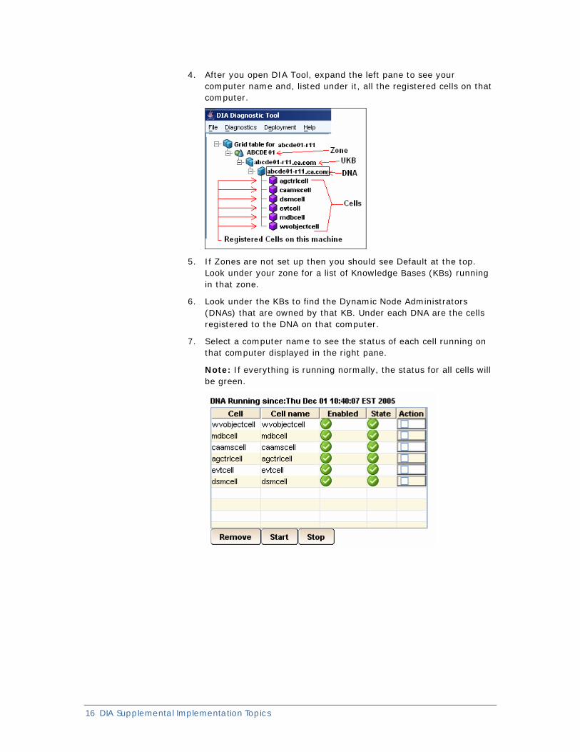
4. After you open DIA Tool, expand the left pane to see your computer name and, listed under it, all the registered cells on that computer.
5. If Zones are not set up then you should see Default at the top. Look under your zone for a list of Knowledge Bases (KBs) running in that zone.
6. Look under the KBs to find the Dynamic Node Administrators (DNAs) that are owned by that KB. Under each DNA are the cells registered to the DNA on that computer.
7. Select a computer name to see the status of each cell running on that computer displayed in the right pane.
Note: If everything is running normally, the status for all cells will be green.
Reregistering Cells
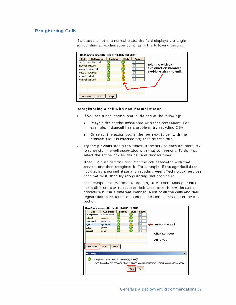
If a status is not in a normal state, the field displays a triangle surrounding an exclamation point, as in the following graphic:
Reregistering a cell with non-normal status
1. If you see a non-normal status, do one of the following:
■ Recycle the service associated with that component. For example, if dsmcell has a problem, try recycling DSM.
■ Or select the action box in the row next to cell with the problem (so it is checked off) then select Start.
2. Try the previous step a few times; if the service does not start, try to reregister the cell associated with that component. To do this, select the action box for the cell and click Remove.
Note: Be sure to first unregister the cell associated with that service, and then reregister it. For example, if the agctrlcell does not display a normal state and recycling Agent Technology services does not fix it, then try reregistering that specific cell.
Each component (WorldView, Agents, DSM, Event Management) has a different way to register their cells; most follow the same procedure but in a different manner. A list of all the cells and their registration executable or batch file location is provided in the next section.
General DIA Deployment Recommendations 17
18 DIA Supplemental Implementation Topics
3. After the cell has been removed, open a command prompt, and move (CD) to the directory associated with that component.
For an agctrlcell example, the registration batch file is located at: InstallPath\CA\SC\CCS\AT\CELLS.
4. From the command line run InstallAgctrlCell.bat to reregister the agctrlcell. The utility InstallDsmCell.bat, which is found in the same directory, can then be used to reregister the DSM cell.
Component Registration Cell Locations
The following list shows where all the component registration batch or executable files are located:
Agent Control cell
Location: InstallPath\CA\SC\CCS\AT\CELLS\InstallAgctrlCell.bat
DSM Control
Location: InstallPath\CA\SC\CCS\AT\CELLS\InstallDsmCell.bat
WV Cell
InstallPath\CA\SC\CCS\WVEM\BIN\regwvcell.bat InstallPath\CA\SC\CCS\WVEM\BIN\Unregwvcell.bat
MDB
InstallPath\CA\SC\MDBCell\bin\mdbreg.bat InstallPath\CA\SC\MDBCell\bin\mdbdereg.bat For example: Echo mdbreg nsmadmin mypasswd EI
CAEM
InstallPath\CA\SC\CCS\WVEM\BIN\caemscellreg.exe /?
Registration Utility Example
Here is an example of how to run a component registration batch or executable file using the CaEmsCell registration utility.
The syntax for the CaEmsCell registration is as follows:
caemscellreg [reg [cell-path] | dereg ]
reg
Indicates that the default action is to register the cell.
cell-path
Defaults to the location of this utility and specifies the location of the cell's materials (jars, dlls, and so forth)
Note: For more information about component registration, see “DIA Reference” in the CA NSM Implementation Guide in the section Consumer Applications.
AutoactivateDNA The autoactivatedna command lets you change the current CA DNA’s owner. Determine which computer is your computer’s current DNA owner by looking at the Knowledge Base configuration file, ukb.dat, located at InstallPath\CA\SC\CCS\DIA\dia\dna\config.
The AutoactivateDNA.bat command is located at: InstallPath\CA\SC\CCS\DIA\dia\dna\bin\
autoactivatedna.bat UKB_Host_Name
When both UKB and DNA are installed on a computer, DNA can be activated only to its local UKB. In other words, as long as the local UKB is installed, the autoactivedna script will always activate the local DNA to a local UKB.
Therefore, the local UKB must be running during local DNA activation, otherwise you see a message such as the following:
Note: Make sure local ukb service or daemon is running, otherwise activation would fail.
Note: You can also use the autoactivatedna command if you just set up your Master KB or local UKB and need to point to it.
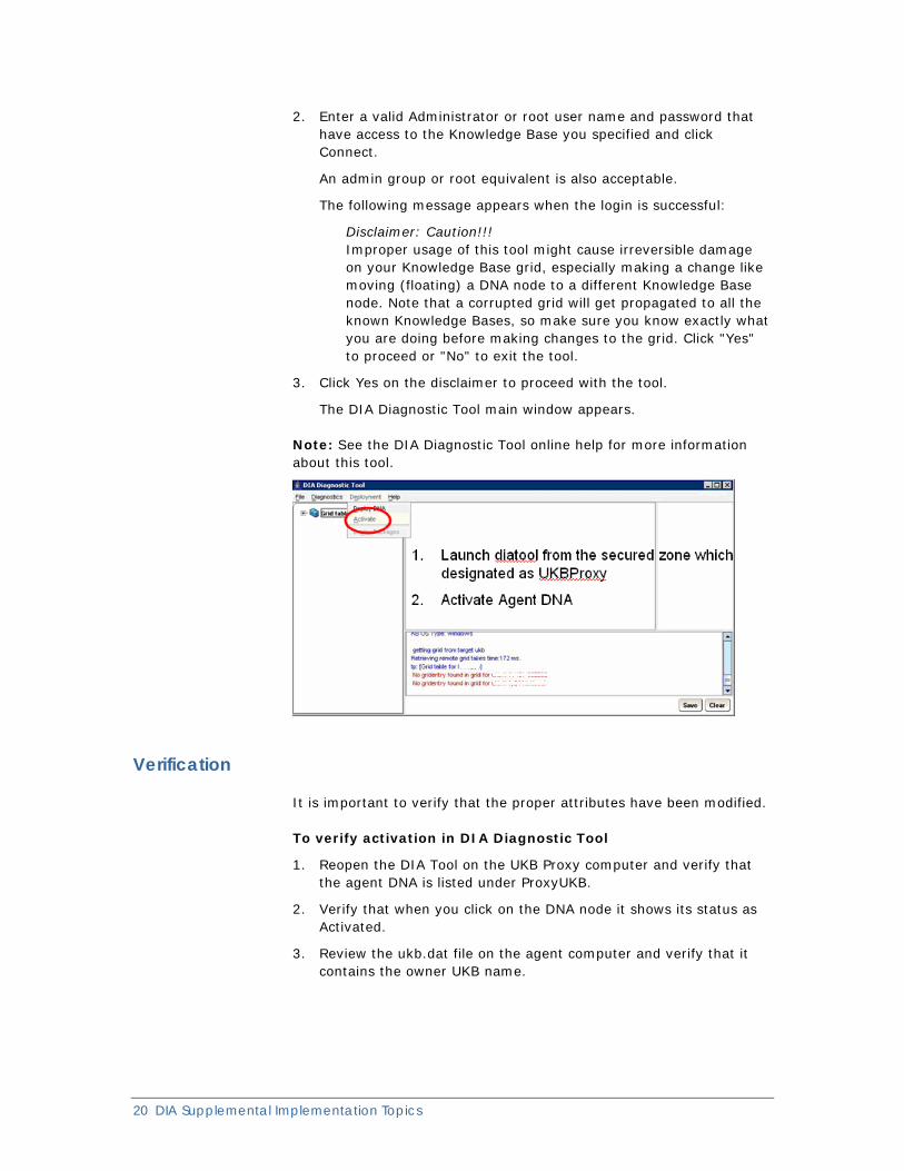
Activate UKB using the DIA Tool
In this scenario of a strict firewall where no inbound ports are open, activation needs to be performed from the manager, so you can activate UKB using the DIA Tool. Run the DIA Diagnostic Tool to monitor all aspects of your DIA infrastructure. It can be launched in the secured zone, which is designated as the UKB proxy.
1. Execute the following command based on your operating environment:
■ On Windows, run the following command in the InstallPath\CA\SC\CCS\DIA\dia\ukb\bin directory:
diatool.bat kb host
■ On Linux or UNIX, run the following command in the $CA_DIA_HOME/dia/ukb/bin directory:
./diatool.sh kb host
kb host
Specifies the name or IP address of the Knowledge Base you want to connect to.
General DIA Deployment Recommendations 19
20 DIA Supplemental Implementation Topics
2. Enter a valid Administrator or root user name and password that have access to the Knowledge Base you specified and click Connect.
An admin group or root equivalent is also acceptable.
The following message appears when the login is successful:
Disclaimer: Caution!!! Improper usage of this tool might cause irreversible damage on your Knowledge Base grid, especially making a change like moving (floating) a DNA node to a different Knowledge Base node. Note that a corrupted grid will get propagated to all the known Knowledge Bases, so make sure you know exactly what you are doing before making changes to the grid. Click "Yes" to proceed or "No" to exit the tool.
3. Click Yes on the disclaimer to proceed with the tool.
The DIA Diagnostic Tool main window appears.
Note: See the DIA Diagnostic Tool online help for more information about this tool.
Verification
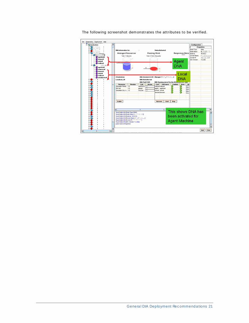
It is important to verify that the proper attributes have been modified.
To verify activation in DIA Diagnostic Tool
1. Reopen the DIA Tool on the UKB Proxy computer and verify that the agent DNA is listed under ProxyUKB.
2. Verify that when you click on the DNA node it shows its status as Activated.
3. Review the ukb.dat file on the agent computer and verify that it contains the owner UKB name.
General DIA Deployment Recommendations 21
The following screenshot demonstrates the attributes to be verified.

Chapter 3: Securing DIA with Encryption
All host-level outbound data communication generated from DIA components (DNA or KB) can use secure sockets. In addition, you can secure the data transfer for all of these communications by configuring them to use public/private keys.
When you configure a computer with DIA to work in the encrypted mode, all other DIA enabled nodes (including Master KB) must be encrypted for them to talk to one another.
Note: A mixed environment is NOT supported where some nodes are configured to use encryption while others are not.
Configure DIA All DIA communication (Grid Synchronization, Activations, and so forth) is based on Java RMI. By default DIA communication is not encrypted, however, you can configure it for encryption by creating an encryption key.
Configure DIA for Encryption
To configure DIA communication for encryption
1. Stop the Dynamic Node Administrator (DNA) and Knowledge Base services
a. Launch the Windows Services user interface.
b. Select the services CA DIA 1.3 DNA and CA DIA 1.3 Knowledge Base, which should display a status of Started.
c. Right-click and select Stop for those two services.
2. Access the DNA configuration file located at InstallPath\CA\SC\CCS\DIA\dia\dna\config\dna.cfg and set RMI_ENCRYPTION to 1.
Dynamic Node Administrator is now configured for encryption on that DNA host.
Note: All DNA hosts must be configured in this way.
Securing DIA with Encryption 23
24 DIA Supplemental Implementation Topics
3. Access the UKB configuration file located at InstallPath\CA\SC\CCS\DIA\dia\ukb\config\ukb.cfg and set RMI_ENCRYPTION to 1.
The Knowledge Base is now configured for encryption on that host.
Note: All Knowledge Bases must be configured in this way.
4. By default, a non-expired encryption key is located at InstallPath\CA\SC\CCS\DIA\dia\config\mykey. This is a sample that can be used for your encryption key, or you can create your own key.
Create an Encryption Key
If you must create an encryption key, it can be done by using the java utility keytool that comes with the java SDK. The password for the keystore must be unicenter. The following commands are examples of using the tool to generate the "mykey" key file for a 360-day validity period.
To Create an Encryption Key
1. Execute the keytool utility using the following parameters:
a. On Windows, this command example has the following format:
InstallPath\CA\SC\JRE.ccs\1.5.0_11\bin\keytool -genkey -keypass unicenter -keystore mykey -storepass unicenter -validity 360 -dname CN=Server, OU=Bar, O=Foo, L=Some, ST=Where, C=UN
b. On Linux or UNIX, this command example has the following format:
/opt/CA/SC/JRE/1.5.0_11/bin/keytool -genkey -keypass unicenter -keystore mykey -storepass unicenter -validity 360 -dname CN=Server, OU=Bar, O=Foo, L=Some, ST=Where, C=UN
Important! This command should be run with the exact keypass, keystore and storepass arguments as shown. The command will not work if the store password is something other than unicenter.
This command has the following format:
■ -certreq [-v] [-protected]
[-alias <alias>] [-sigalg <sigalg>] [-file <csr_file>] [-keypass <keypass>] [-keystore <keystore>] [-storepass <storepass>] [-storetype <storetype>] [-providerName <name>] [-providerClass <provider_class_name> [-providerArg <arg>]] ...
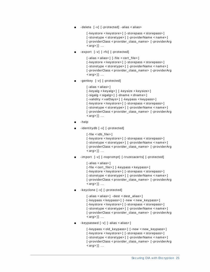
■ -delete [-v] [-protected] -alias <alias>
[-keystore <keystore>] [-storepass <storepass>] [-storetype <storetype>] [-providerName <name>] [-providerClass <provider_class_name> [-providerArg <arg>]] ...
■ -export [-v] [-rfc] [-protected]
[-alias <alias>] [-file <cert_file>] [-keystore <keystore>] [-storepass <storepass>] [-storetype <storetype>] [-providerName <name>] [-providerClass <provider_class_name> [-providerArg <arg>]] ...
■ -genkey [-v] [-protected]
[-alias <alias>] [-keyalg <keyalg>] [-keysize <keysize>] [-sigalg <sigalg>] [-dname <dname>] [-validity <valDays>] [-keypass <keypass>] [-keystore <keystore>] [-storepass <storepass>] [-storetype <storetype>] [-providerName <name>] [-providerClass <provider_class_name> [-providerArg <arg>]] ...
■ -help
■ -identitydb [-v] [-protected]
[-file <idb_file>] [-keystore <keystore>] [-storepass <storepass>] [-storetype <storetype>] [-providerName <name>] [-providerClass <provider_class_name> [-providerArg <arg>]] ...
■ -import [-v] [-noprompt] [-trustcacerts] [-protected]
[-alias <alias>] [-file <cert_file>] [-keypass <keypass>] [-keystore <keystore>] [-storepass <storepass>] [-storetype <storetype>] [-providerName <name>] [-providerClass <provider_class_name> [-providerArg <arg>]] ...
■ -keyclone [-v] [-protected]
[-alias <alias>] -dest <dest_alias>] [-keypass <keypass>] [-new <new_keypass>] [-keystore <keystore>] [-storepass <storepass>] [-storetype <storetype>] [-providerName <name>] [-providerClass <provider_class_name> [-providerArg <arg>]] ...
■ -keypasswd [-v] [-alias <alias>]
[-keypass <old_keypass>] [-new <new_keypass>] [-keystore <keystore>] [-storepass <storepass>] [-storetype <storetype>] [-providerName <name>] [-providerClass <provider_class_name> [-providerArg <arg>]] ...
Securing DIA with Encryption 25
26 DIA Supplemental Implementation Topics
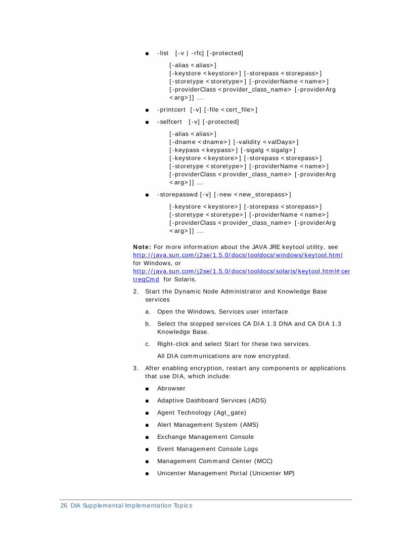
■ -list [-v | -rfc] [-protected]
[-alias <alias>] [-keystore <keystore>] [-storepass <storepass>] [-storetype <storetype>] [-providerName <name>] [-providerClass <provider_class_name> [-providerArg <arg>]] ...
■ -printcert [-v] [-file <cert_file>]
■ -selfcert [-v] [-protected]
[-alias <alias>] [-dname <dname>] [-validity <valDays>] [-keypass <keypass>] [-sigalg <sigalg>] [-keystore <keystore>] [-storepass <storepass>] [-storetype <storetype>] [-providerName <name>] [-providerClass <provider_class_name> [-providerArg <arg>]] ...
■ -storepasswd [-v] [-new <new_storepass>]
[-keystore <keystore>] [-storepass <storepass>] [-storetype <storetype>] [-providerName <name>] [-providerClass <provider_class_name> [-providerArg <arg>]] ...
Note: For more information about the JAVA JRE keytool utility, see http://java.sun.com/j2se/1.5.0/docs/tooldocs/windows/keytool.html for Windows, or http://java.sun.com/j2se/1.5.0/docs/tooldocs/solaris/keytool.html#certreqCmd for Solaris.
2. Start the Dynamic Node Administrator and Knowledge Base services
a. Open the Windows, Services user interface
b. Select the stopped services CA DIA 1.3 DNA and CA DIA 1.3 Knowledge Base.
c. Right-click and select Start for these two services.
All DIA communications are now encrypted.
3. After enabling encryption, restart any components or applications that use DIA, which include:
■ Abrowser
■ Adaptive Dashboard Services (ADS)
■ Agent Technology (Agt_gate)
■ Alert Management System (AMS)
■ Exchange Management Console
■ Event Management Console Logs
■ Management Command Center (MCC)
■ Unicenter Management Portal (Unicenter MP)
Securing DIA with Encryption 27
■ Unicenter Configuration Manager
■ Web Reporting Server (WRS)
■ WorldView
The applications will then establish an encrypted connection to DIA.
Note: Once again, if encryption is used, it must be used everywhere in the environment. A mixed mode scenario is not supported.
Patches Required As of the publishing date of this guide, the fix required for encryption for NSM r11.1 has been published.
Note: For r11.1, one patch addresses the addition of a new entry in the dna.cfg file called SecondaryMasterKB, which is described in the following sections of this guide. (CA NSM r11.2 already contains this fix.)
Other DIA patches are available that address a number of issues and they should be applied to the appropriate operating environments.
Please note the DIA patches and their corresponding platforms:
AIX R11.0
QO95131
HP R11.0
QO95132
Linux R11.0
QO95130
Sun R11.0
QO95133
Windows R11.1
QO93598
Windows R11.1 (only updates files on UKB that are pushed to DNAs during activation)
QO95134

Chapter 4: Ports Used by DIA DIA uses the same port for all communications so that there is no need to configure ports other than the ports required for DIA. DIA can automatically proxy connections for target Dynamic Node Administrator hosts that are located outside the firewall without any interaction or configuration changes by the systems administrators.
Note: DIA does not currently support Unicenter Knowledge Bases located outside a firewall unless in-bound ports are open for connects. However, the Dynamic Node Administrators can be outside of a firewall as long as they are communicating to a Unicenter Knowledge Base inside of the firewall.
The purpose of this chapter is to describe DIA port usage and the configuration of ports required in firewall environments to enable CA NSM components to function successfully.
Main Ports Used by DIA DIA uses the following ports for the communication: 11501, 11502, 11503 and 11504.
Important: The four main DIA ports cannot be customized in NSM r11.x. There are known issues with changing the port numbers in the current versions of CA NSM.
The following list summarizes how the basic DIA ports can be used in firewall environments. More specific details are presented in the following sections.
DNA ports: 11501 and 11502
■ These ports are used for communication with and between the DNAs.
■ The ports are normally used as a pair.
■ In a firewall environment, the following cases must be considered:
1. For default DNA communication crossing a firewall, you must enable both ports to be bidirectional
2. For proxy UKB to DNA communication crossing a firewall (such as a DSM inside the firewall communicating with an agent outside), both ports need to be opened but only for the
direction from the UKB (typically the DSM) to the DNA. UKB Proxy setting controls only UKB to DNA communication. It has no affect on UKB to UKB communication. Note: The proxy setting will not affect Agent View communications. Bidirectional communication is still required for Agent View.
Ports Used by DIA 29
30 DIA Supplemental Implementation Topics
UKB ports: 11503 and 11504
■ These ports are used for communication with and between the UKBs.
■ The ports are normally used as a pair.
■ In a firewall environment, the following cases must be considered:
■ For default UKB to DNA communication crossing a firewall, you must open both ports, but in one direction only, from the DNA to the UKB.
■ For proxy UKB to DNA communication crossing a firewall, you do not need to open any UKB ports. However, this firewall configuration prevents the normal DNA activation to occur and special procedures are required to activate the DNAs from the UKB side.
■ For UKB to UKB communication crossing a firewall, both ports must be enabled to be bidirectional (between all UKBs, including, of course, the Master UKBs).
Note: The UKB Proxy setting controls only UKB to DNA communication. It does not affect UKB to UKB communications.
Ports Used by DIA Push Model Communication The DIA push model enables DIA cells to send data directly to DIA clients by bypassing normal routing of DIA traffic. Several components within CA NSM take advantage of the DIA push model. Push technology is used by event and alert cells to provide event and alert logs to Management Command Center (MCC) and Unicenter Management Portal (Unicenter MP).
Unicenter MP and MCC pass a port number to the event or alert cell indicating that Unicenter MP and MCC expect data from the cell to be sent to this port. By default, DIA does not restrict the ports chosen by DIA push model communication, but you can restrict the port range by changing configuration parameters.
Port Range for Management Command Center In a firewall environment where the outbound communication is blocked for all but selected ports, such as the DIA ports 11501-11504, an MCC client outside a firewall hangs when it tries to display the CA NSM Console Log from a node inside the firewall. The MCC client hangs because by default the MCC creates a new listener on an unspecified free port to receive the console log data. This problem does not happen in a traditional firewall where the outbound communication is not blocked.
This section describes how to configure a range of ports used by the MCC client when communicating to DIA alert and event cells. The range of ports can then be opened outbound. The range of ports must include a sufficient number of free ports on the MCC Client node to accommodate the expected maximum number of parallel MCC client sessions.
To specify a range of ports used by MCC client to communicate to DIA alert and event cells
1. Open the dna.cfg file, which is located at InstallPath\CA\SC\CCS\DIA\dia\dna\config
2. Add the following lines in the section before "Define the logger properties:”
# The beginning port number of the range MinPCRMIPort = port number # The end port number of the range MaxPCRMIPort = port number
3. Recycle CA DIA 1.3 DNA service.
Port Range for Unicenter Management Portal In a firewall environment where the outbound communication is blocked for all but selected ports, such as the DIA ports 11501-11504, a Management Portal server outside a firewall cannot access information from CA NSM Console Log nor the CA NSM Alert Management running on a node inside the firewall. Communication between Unicenter MP and event and alert cells is disrupted because by default the Unicenter MP creates a new listener on an unspecified free port to receive the console log and alert data. This scenario does not happen in a traditional firewall where the outbound communication is not blocked.
This section describes how to configure a range of ports used by the Unicenter MP when communicating to DIA alert and event cells. The port range is required in cases where more than one consumer would like to receive data through push technology. Depending on the probability of this happening, the port range is expected to be somewhere between 5 and 10. You can set up these port numbers for communication.
To specify a range of ports used by Unicenter Management Portal to communicate to DIA alert and event cells
IMPORTANT: NSM 11.1 users must apply UMP patch QO94404.
Ports Used by DIA 31
32 DIA Supplemental Implementation Topics
If DNA is installed on the Unicenter MP computer
1. Open the dna.cfg file under (Windows) InstallPath\CA\SC\CCS\DIA\dia\dna\config, or (UNIX) Diahome\dia\dna\config
2. Define the range of the port by adding the following lines in the section before "Define the logger properties:” # The begining port number of the range MinPCRMIPort = <port number> # The end port number of the range MaxPCRMIPort = <port number>
3. Recycle CA DIA 1.3 DNA service.
If DNA is NOT installed on the Management Portal computer
1. Open the wrapper.conf file located at PortalHome\jakarta-tomcat-4.1.29\conf\wrapper.conf.
2. Add or modify the following lines: wrapper.java.additional.16=-DMinPCRMIPort=<port number> wrapper.java.additional.17=-DMaxPCRMIPort=<port number> #ADDITIONAL_JAVA_OPTIONS wrapper.java.additional.18.stripquotes=TRUE
3. Restart the CA Cleverpath Portal service.
Chapter 5: DIA Node Management The Distributed Intelligence Architecture (DIA) Diagnostic Tool is a component of CA NSM that provides troubleshooting and management of all aspects of the DIA infrastructure from any knowledge base. The DIA Diagnostic Tool was originally designed for administrative and support personnel. Care must be taken when using this tool so that your NSM environment is not negatively impacted.
The DIA Diagnostic Tool is installed as part of the Knowledge Base installation and is located on Windows at InstallPath\CA\SC\CCS\DIA\dia\ukb\bin\diatool.bat and on UNIX or Linux at $CA_DIA_HOME/dia/ukb/bin/diatool.bat.
This chapter contains information about managing DIA nodes using the DIA Rule Editor (with a sample rule file), DIA operational tips, DIA Utilities, and DIA questions and answers.
DIA Rule Editor The DIA Rule execution module writes rules for DIA in XML (eXtensible Markup Language). The module writes rules for host names of computers, IP addresses of computers, or complete subnets. The Knowledge Base Rule Editor lets you modify the XML Rule file that resides on the Master Knowledge Base, which is defined by an entry in the DNS.
Rules can be written for two reasons:
■ Zone - Defines the zone information of Knowledge Bases (the zone rule)
■ Owner - Defines the Dynamic Node Administrator ownership, or which DNA computer must be managed (or owned) by which Knowledge Base host (the activation rule)
Each rule has match cases and an Otherwise match case associated with it. The match case defines the criteria for assigning zone or ownership. The match can be based on IP address or host name.
The rule is evaluated top down by the Master KB in response to get zone requests by the Knowledge Base during service startup or grid synchronization and get ownership requests by DNA during activation, especially in a DNA-only installation.
DIA Node Management 33
34 DIA Supplemental Implementation Topics
In a manager system where we have both Knowledge Base and DNA, it is necessary to define only the match case for the Knowledge Base in the zone rule since the DNA is automatically activated to the local Knowledge Base without having to request ownership information from the Master Knowledge Base.
If the requester's host name or IP address does not match any of the match cases, the default value defined in the Otherwise match case is returned.
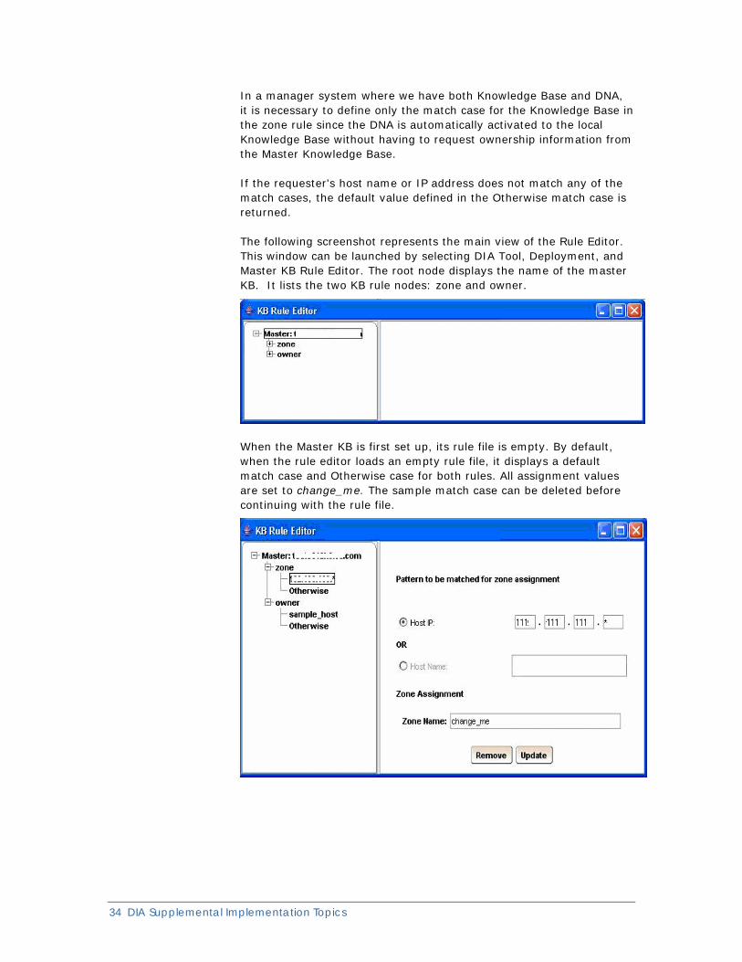
The following screenshot represents the main view of the Rule Editor. This window can be launched by selecting DIA Tool, Deployment, and Master KB Rule Editor. The root node displays the name of the master KB. It lists the two KB rule nodes: zone and owner.
When the Master KB is first set up, its rule file is empty. By default, when the rule editor loads an empty rule file, it displays a default match case and Otherwise case for both rules. All assignment values are set to change_me. The sample match case can be deleted before continuing with the rule file.
Sample Rule File The following example shows a sample rule file that has already been set up.
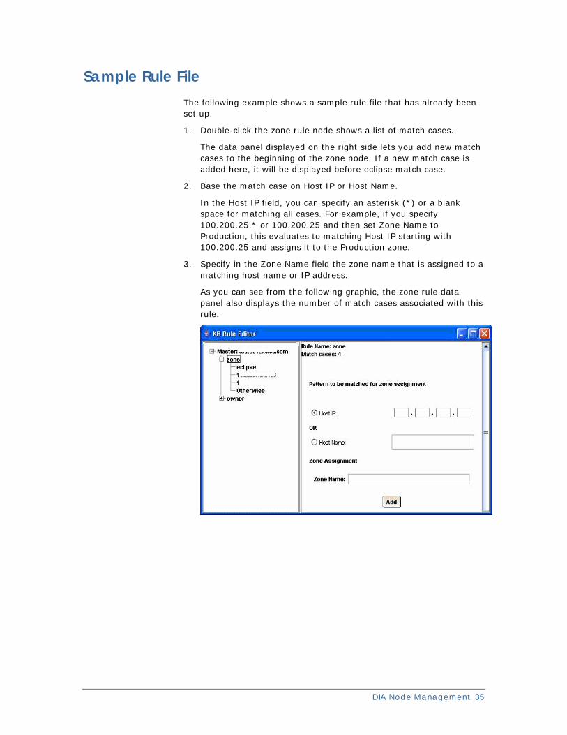
1. Double-click the zone rule node shows a list of match cases.
The data panel displayed on the right side lets you add new match cases to the beginning of the zone node. If a new match case is added here, it will be displayed before eclipse match case.
2. Base the match case on Host IP or Host Name.
In the Host IP field, you can specify an asterisk (*) or a blank space for matching all cases. For example, if you specify 100.200.25.* or 100.200.25 and then set Zone Name to Production, this evaluates to matching Host IP starting with 100.200.25 and assigns it to the Production zone.
3. Specify in the Zone Name field the zone name that is assigned to a matching host name or IP address.
As you can see from the following graphic, the zone rule data panel also displays the number of match cases associated with this rule.
DIA Node Management 35
36 DIA Supplemental Implementation Topics
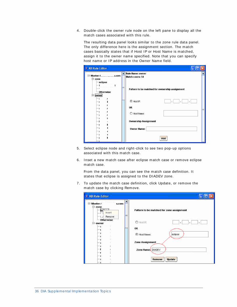
4. Double-click the owner rule node on the left pane to display all the match cases associated with this rule.
The resulting data panel looks similar to the zone rule data panel. The only difference here is the assignment section. The match cases basically states that if Host IP or Host Name is matched, assign it to the owner name specified. Note that you can specify host name or IP address in the Owner Name field.
5. Select eclipse node and right-click to see two pop-up options associated with this match case.
6. Inset a new match case after eclipse match case or remove eclipse match case.
From the data panel, you can see the match case definition. It states that eclipse is assigned to the DIADEV zone.
7. To update the match case definition, click Update, or remove the match case by clicking Remove.
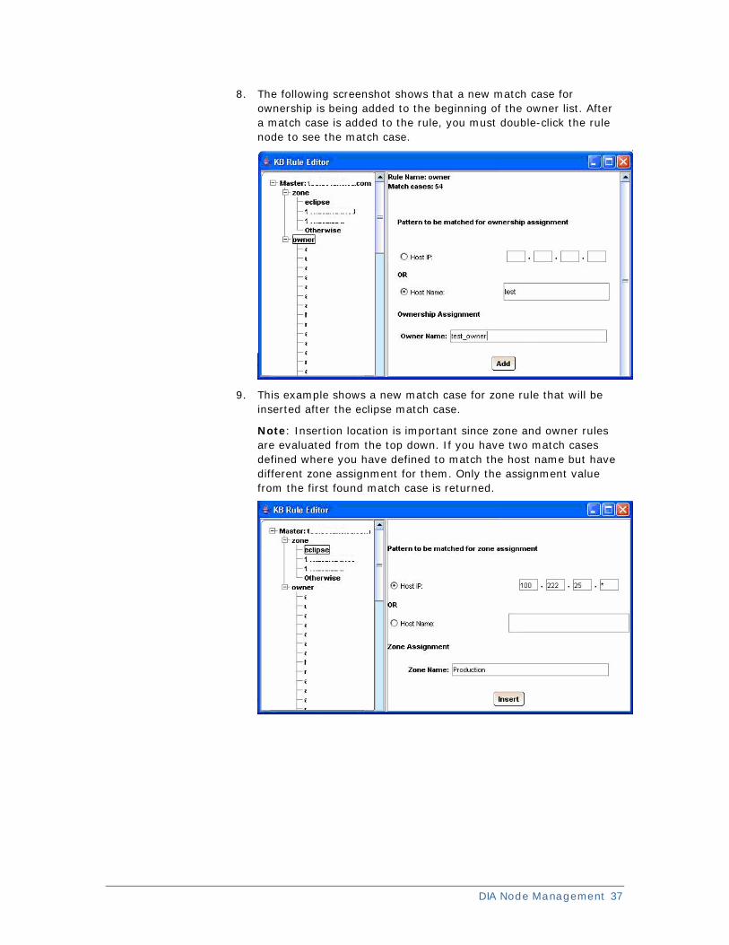
8. The following screenshot shows that a new match case for ownership is being added to the beginning of the owner list. After a match case is added to the rule, you must double-click the rule node to see the match case.
9. This example shows a new match case for zone rule that will be inserted after the eclipse match case.
Note: Insertion location is important since zone and owner rules are evaluated from the top down. If you have two match cases defined where you have defined to match the host name but have different zone assignment for them. Only the assignment value from the first found match case is returned.
DIA Node Management 37
38 DIA Supplemental Implementation Topics
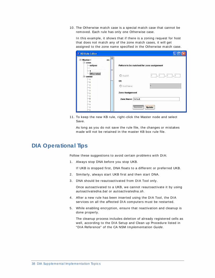
10. The Otherwise match case is a special match case that cannot be removed. Each rule has only one Otherwise case.
In this example, it shows that if there is a zoning request for host that does not match any of the zone match cases, it will get assigned to the zone name specified in the Otherwise match case.
11. To keep the new KB rule, right-click the Master node and select Save.
As long as you do not save the rule file, the changes or mistakes made will not be retained in the master KB box rule file.
DIA Operational Tips Follow these suggestions to avoid certain problems with DIA:
1. Always stop DNA before you stop UKB.
If UKB is stopped first, DNA floats to a different or preferred UKB.
2. Similarly, always start UKB first and then start DNA.
3. DNA should be reautoactivated from DIA Tool only.
Once autoactivated to a UKB, we cannot reautoactivate it by using autoactivatedna.bat or autoactivatedna.sh.
4. After a new rule has been inserted using the DIA Tool, the DIA services on all the affected DIA computers must be restarted.
5. While enabling encryption, ensure that reactivation and cleanup is done properly.
The cleanup process includes deletion of already registered cells as well, according to the DIA Setup and Clean up Procedure listed in “DIA Reference” of the CA NSM Implementation Guide.
DIA Utilities Certain utilities are available to help in troubleshooting and managing the DIA component more efficiently. These utilities are provided as an add-on feature to the existing DIA functionality.
This list of utilities is the same as the list found in the CA NSM Implementation Guide as part of the product documentation but the utilities are added here as a convenience.
Knowledge Base-Related Utilities
The following utilities can be found at CA\SC\CCS\DIA\dia\ukb\bin directory. Windows batch files, as well as UNIX/Linux shell scripts, are provided as a part of utilities.
getMasterKB
Use the getMasterKB utility to get the Master KB of the specified doc.
Syntax
getMasterKB.bat KB_Host_Name|IP
KB_Host_Name|IP
Specifies the Knowledge Base host for which you want to get the Master KB
The files used to run the utility are: getMKBName.class, getMasterKB.bat (Windows), getMasterKB.sh (UNIX/Linux).
getOwnerKB
Use the getOwnerKB utility to get the Knowledge Base owner of a given Dynamic Node Administrator host.
Syntax
getOwnerKB.bat DNA_Host_Name|IP
DNA_Host_Name|IP
Specifies the Dynamic Node Administrator host for which you want to get the KB owner.
The files used to run the utility are: getOwnerUKB.class, getOwnerUKB.bat (Windows), getOwnerUKB.sh (UNIX/Linux).
DIA Node Management 39
40 DIA Supplemental Implementation Topics
getSRVInfo
Use the getSRVInfo utility to get the SRV records of the domain.
Syntax
getSRVInfo.bat domain name
domain name
Specifies the current domain name. Specifying the domain name is optional for Linux or UNIX if the domain name entry is present in the /etc/resolve.conf file.
The files used to run the utility are: estDNS.class, getSRVInfo.bat (Windows), getSRVInfo.sh (UNIX/Linux).
refreshZone
Use the refreshZone utility to reload the Master Knowledge Base rule file, refresh the zone or grid, or reset the zone.
Syntax
refreshzone.bat kb|zone|reset mode_value
kb|zone|reset
Specifies the mode the utility is to use.
■ The kb mode reloads the rule file of the Master Knowledge Base or synchronizes grid and zone information of a Knowledge Base with the Master Knowledge Base.
■ The zone mode contacts all Knowledge Bases in the zone to synchronize zone and grid information with the Master Knowledge Base.
■ The reset mode is used primarily when the zone of a Knowledge Base changes and there is still a stale entry in the old zone. The reset mode takes time to run if there are many Knowledge Bases in the old and new zones. The process notifies every Knowledge Base in the old zone to remove the stale Knowledge Base entry.
mode_value
Specifies the Knowledge Base name or zone name on which to take action.
■ If you specify the kb mode, the mode_value should be the name or IP address of the Knowledge Base. If you specify the Master Knowledge Base name, the utility reloads the rule file. If you specify the regular Knowledge Base name, the grid and zone information of the Knowledge Base is synchronized with the Master Knowledge Base.
■ If you specify the zone mode, the mode_value should be the zone name you want to reset and the utility contacts every Knowledge Base in the zone you specify to synchronize the zone and grid of each Knowledge Base with the Master Knowledge Base.
■ If you specify the reset mode, the mode_value should be the name of the Knowledge Base that still has an entry in the old zone.
Example1: kb mode
refreshZone.bat kb knowledgebase1
Example2: zone mode
refreshZone.bat zone zone1
Example3: reset mode
refreshZone.bat reset knowledgebase2
The files used to run the utility are: refreshZone.bat (Windows), refreshZone.sh (UNIX/Linux).
getZone
This utility is used for getting KB zone name from the master KB as per the rules set for it.
Syntax
getzone.bat Master KB Host Name/IP
Master KB
Specifies the name of the master KB
Host Name/IP
Specifies the KB host for which you want to get the zoning information.
The files used to run the utility are: getZone.bat (Windows), getZone.sh (UNIX/Linux).
Dynamic Node Administrator-Related Utilities
The following utilities can be found under the CA\SC\CCS\DIA\dia\dna\bin directory.
GetRegisteredCells
Use the GetRegisteredCells utility to get a list of registered cells on a particular Dynamic Node Administrator.
Syntax
GetRegisteredCells.bat DNA_Host_Name|IP_Address
DNA Host Name|IP Address
Specifies the name of the DNA host or its IP address on which we want to see the cell information.
Note: This returns only the external cell list (for example, the CA NSM cells are all external cells, and cells like pdicell are DIA internal cells)
The files used to run the utility are: GetRegisteredCells.bat (Windows), GetRegisteredCells.sh (UNIX/Linux).
DIA Node Management 41
42 DIA Supplemental Implementation Topics
GetCellInfo
Use the GetCellInfo utility to get cell information from a particular Dynamic Node Administrator.
Syntax
GetCellInfo.bat DNA_Host_Name|IP Address Cell_Name
DNA Host Name|IP Address
Specifies the name of the DNA host or IP address on which we want to see the cell information.
Cell Name
Specifies the name of the cell about which you want to get information.
Note: This will return the information about the external cells only (for example, the CA NSM cells are all external cells, and cells like pdicell are DIA internal cells)
The files used to run the utility are: GetCellInfo.bat (Windows), GetCellInfo.sh (UNIX/Linux).
setLogLevel
Use the setLogLevel utility to set the logging level of a particular Dynamic Node Administrator or UKB. The files used to run the utility are: setLogLevel.bat (Windows), setLogLevel.sh (UNIX/Linux).
Syntax
setLogLevel dna|ukb|cgene hostname loglevel
dna|ukb|cgene
Specifies whether the logging level is to be set for a Dynamic Node Administrator, a Knowledge Base, or a C-Gene.
hostname
Specifies hostname of DNA or UKB whose logging level you want to change.
loglevel
Specifies the logging level you want to set. Valid values are: OFF, SEVERE, WARNING, INFO, CONFIG, FINE, FINER, FINEST, and ALL.
Note: This changes the logging level that is in process. DNA/UKB is not required to be restarted in order to make this change effective. The log level set by the setLogLevel utility is applied at runtime. The log level in configuration files is applied at the time of startup only.
DIA Node Management 43
updateConfigFile
This utility is used for changing the configuration files of UKB, DNA, cell, or cgene on DIA systems.
Syntax:
updateConfigFile.bat hosts_file_name config_file_name property_name property_value
hosts_file_name
Specifies the file name that stores the host names or IP addresses of the UKBs and DNAs
config_file_name
Specifies the name of the configuration file in which the configuration information is going to be changed, for example, UKB, DNA, cell, or C-gene.
property_name
Specifies the name of the property that needs to be changed.
property_value
Specifies the new value of the property.
Note: The LOG property is updated during runtime but not in the configuration files. For all other properties, a restart of the service is required.

Chapter 6: DIA Tips, Tricks & Solutions DIA Tips,Tricks & Solutions chapter is a collection of DIA procedures, tips contributed from the CA NSM technical development team, and solutions contributed from Technical Support staff. The following topics are covered:
DIA Tips and Tricks
■ Agents not Discovered—Pingagt not Working
■ Agent-Only Upgrade to Manager
■ Deactivation through DIA TOOL
■ DNA activation issues
■ Cluster—Activation
■ Cluster—DIA Setup
■ Cluster—Master KB Configuration Setup
■ DIA Master Knowledge Base on Cluster
■ DIA Important Points to Consider
■ Domain Change
■ Encrypted and Non-Encrypted Computers in a Network
■ Encrypted Environment—Master KB
■ Encrypting DIA—Best Practices
■ Firewall—Typical Setup
■ Installation Agent-Only
■ Installation Manager
■ IPv6 Prerequisites
■ Link Local Addresses
■ Master KB—Moving
■ Master KB—Overload
■ Mixed Environments
■ Pure IPv6 Agent Floating
■ Rules Evaluation
■ SRV Record Override
■ UNIX Installations—DIA Errors on AIX
■ UNIX Installations—DIA TOOL on Pure IPv6
■ UNIX Installations—JRE not found Error
■ UNIX Installations—Log in Failure to DIA TOOL
■ UNIX Installations—More than one Domain
■ Zone infraction error
DIA Tips, Tricks & Solutions 45
46 DIA Supplemental Implementation Topics
■ Zone Moving DNA
■ Zone Update Issues
DIA Symptoms and Solutions
■ DSM cannot communicate with agents & other DIA communication problems
■ During installation DIA was unable to retrieve DNS SRV class record
■ I cannot identify my DNA’s current owner
Questions and Answers
■ DNA floating—what is it?
■ How can DNA floating be controlled?
■ How do I configure DIA in a firewall environment?
■ How do I configure DIA for debugging?
■ How do I verify that the SRV record exists?
■ What is a Master UKB and do I need it?
■ What needs to be done to allow an r11.1 DNA agent node to communicate with an r11.2 UKB (manager node)?
■ What should I do if I have a connection problem between my MasterKB and KB, or the KB and DNA (Activation)?
■ Why do I get DIA error messages on when my MCC client starts up?
DIA Tips and Tricks
Agents Not Discovered - Pingagt not Working 1. Check if the DIA prerequisites are met.
The nslookup (forward and reverse lookup) prerequisites should be met for DIA to work properly.
2. Check if the DNA on the computer is activated.
DNA must be activated in order for the pingagt communication to work.
Agent-Only Upgrade to Manager
If an agent-only computer is upgraded to a manager computer, the local DNA would still point to the previous non-local UKB. It does not automatically activate itself to the local UKB.
First deactivate the DNA, clean up the DNA component, and reactivate the local DNA to the local UKB.
Deactivation through DIA TOOL
In a rare event, DNA cells may not reactivate properly after a deactivation is performed through the DIATool, for instance, when the DIA connection to agents is lost.
Perform Clean Up after Deactivation and reactivate to reregister the cells. Follow the clean up procedure (as outlined in the Appendix “DIA Reference” of the Implementation Guide) to reregister the affected cell.
DNA Activation issues
In cases where DNA is not activated (where the ukb.dat file is not created under dna/config directory), check the following:
1. Are the DIA prerequisites met on that computer?
The prerequisites are listed in this document.
2. Is the firewall enabled on the UKB/DNA computer?
This needs to be disabled if it is present.
Cluster—Activation
While activating a remote DNA to a UKB on a clustered setup, only a virtual name or IP address of the clustered setup must be used. The DNA gets activated to the UKB, which is active at that point of time.
DNAs can also be activated to a UKB on a clustered setup using its physical name, but this method is not recommended. Using the virtual name or IP address of the clustered setup to communicate to the cluster is advisable.
DNAs on a clustered setup will get activated to the local UKB on the clustered set.
DIA Tips, Tricks & Solutions 47
48 DIA Supplemental Implementation Topics
Cluster—Master KB Configuration Setup
The DIA Master KB can be set up in a cluster with the following configuration:
Using SRV
Provide the physical node names of clustered computers as Primary and Secondary KB details.
Using Override SRV
Provide the physical node names for Primary and Secondary KB details in the dna.cfg file, and then restart the DNA and UKB services. For example, diacluster1 could be the Primary KB, while the node diacluster2 could be the Secondary KB.
Cluster—DIA Setup
Clusters are groups of computers that function together as a single entity for the purpose of parallel processing, load balancing, and fault tolerance. Using cluster technology increases the reliability and availability of a computer system. It keeps applications highly available by providing failover capabilities because the system is no longer dependant on a single server. When setting up DIA in a cluster environment you must be aware of the physical and virtual names assigned.
DIA Master Knowledge Base on Cluster
NSM 11.2 addresses the requirement of implementing DIA Master Knowledge Bases (primary and secondary) on a cluster setup. This feature was not available out-of-the-box prior to the CA NSM r11.2 release.
An important point to note is that although DIA is not yet highly-available, NSM r11.2 lets you use your existing cluster setup to implement Master KBs, instead of requiring that you purchase new hardware to do so.
Cluster Node made into Master Knowledge Base
Cluster nodes can be made into Master KBs by having the DNS SRV record set to the physical node names, with the priority set in the appropriate order to make them primary and secondary.
If for some reason the DNS SRV record cannot be modified, you can update the dna.cfg file to override the SRV record and then update the primary and secondary Master KB fields. The physical node names of the cluster should also be set here. For step-by-step procedures, see DIA Support for HACMP Cluster.
Scenarios Tested
Two scenarios were tested and gave positive results (keeping in mind the previous points). Extensive tests were conducted before and after failover.
Scenario One
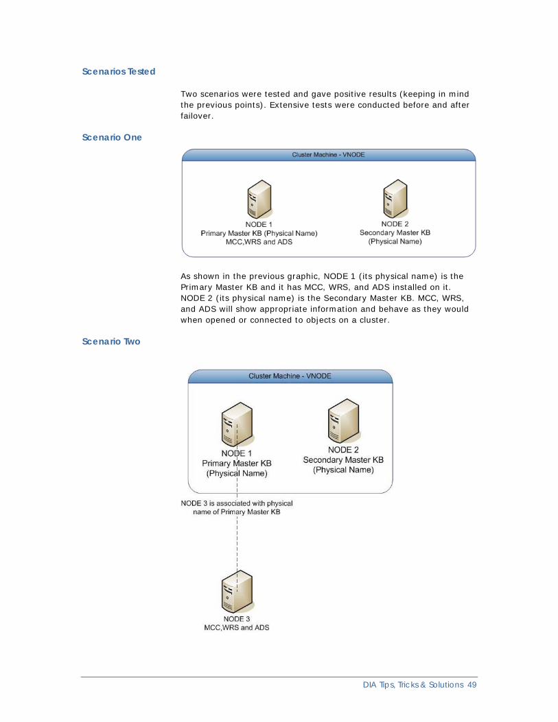
As shown in the previous graphic, NODE 1 (its physical name) is the Primary Master KB and it has MCC, WRS, and ADS installed on it. NODE 2 (its physical name) is the Secondary Master KB. MCC, WRS, and ADS will show appropriate information and behave as they would when opened or connected to objects on a cluster.
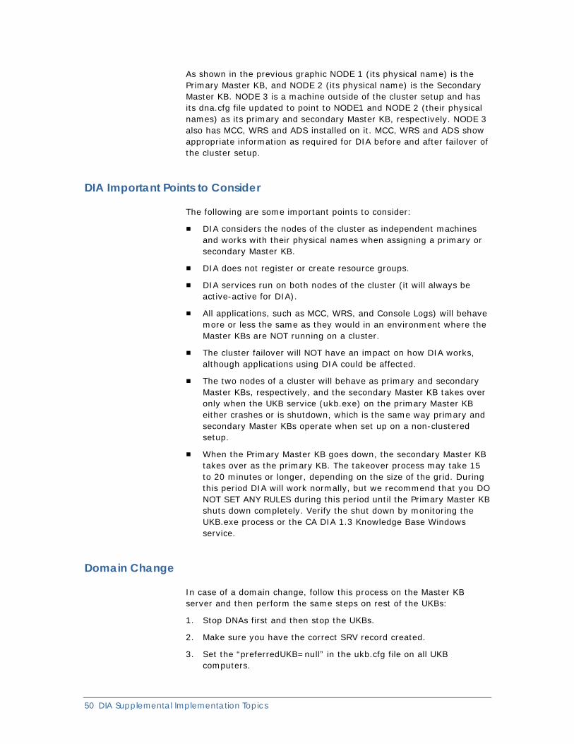
Scenario Two
DIA Tips, Tricks & Solutions 49
50 DIA Supplemental Implementation Topics
As shown in the previous graphic NODE 1 (its physical name) is the Primary Master KB, and NODE 2 (its physical name) is the Secondary Master KB. NODE 3 is a machine outside of the cluster setup and has its dna.cfg file updated to point to NODE1 and NODE 2 (their physical names) as its primary and secondary Master KB, respectively. NODE 3 also has MCC, WRS and ADS installed on it. MCC, WRS and ADS show appropriate information as required for DIA before and after failover of the cluster setup.
DIA Important Points to Consider
The following are some important points to consider:
■ DIA considers the nodes of the cluster as independent machines and works with their physical names when assigning a primary or secondary Master KB.
■ DIA does not register or create resource groups.
■ DIA services run on both nodes of the cluster (it will always be active-active for DIA).
■ All applications, such as MCC, WRS, and Console Logs) will behave more or less the same as they would in an environment where the Master KBs are NOT running on a cluster.
■ The cluster failover will NOT have an impact on how DIA works, although applications using DIA could be affected.
■ The two nodes of a cluster will behave as primary and secondary Master KBs, respectively, and the secondary Master KB takes over only when the UKB service (ukb.exe) on the primary Master KB either crashes or is shutdown, which is the same way primary and secondary Master KBs operate when set up on a non-clustered setup.
■ When the Primary Master KB goes down, the secondary Master KB takes over as the primary KB. The takeover process may take 15 to 20 minutes or longer, depending on the size of the grid. During this period DIA will work normally, but we recommend that you DO NOT SET ANY RULES during this period until the Primary Master KB shuts down completely. Verify the shut down by monitoring the UKB.exe process or the CA DIA 1.3 Knowledge Base Windows service.
Domain Change
In case of a domain change, follow this process on the Master KB server and then perform the same steps on rest of the UKBs:
1. Stop DNAs first and then stop the UKBs.
2. Make sure you have the correct SRV record created.
3. Set the “preferredUKB=null” in the ukb.cfg file on all UKB computers.
4. Change the domain suffix for the UKB computers.
5. Delete all the files from the ukb\config folder except for the following: ukb.cfg, ukbrule.xml, abd remins.cfg.
6. Start the UKB service first and then start the DNA service.
7. Open the ukb.dat file in the dna\config folder and verify that the new FQDN is listed there.
8. Open the gridtable.txt file in ukb\config folder and verify that the UKB name and DNA to UKB pair list for the UKB is correct.
9. Open DIA Tool and verify if the DNAs are registered to their correct owner.
Follow the previous steps in the same order for each computer.
Encrypted and Non-Encrypted Computers in a Network
Communication is not possible between the encrypted and non-encrypted computers. Make sure that the activation of an encrypted agent computer is associated with an encrypted manager computer.
Set Rules so that the encrypted agent computer gets only an encrypted manager computer as its owner.
Encrypted Environment—Master KB
Communication is not possible between the encrypted and non-encrypted computers. Therefore, the Master KB should be encrypted within an encrypted environment.
Ensure that there are only encrypted agents (no non-encrypted agents) in an environment where the Master KB is encrypted. If there are non-encrypted agents in the encrypted Master KB environment, the Master KB in the dna.cfg file should be overridden for all non-encrypted agents to a non-encrypted Master KB.
DIA Tips, Tricks & Solutions 51
52 DIA Supplemental Implementation Topics
Encrypting DIA—Best Practices
Following are the best practices to ensure that DIA communications are encrypted:
1. Stop all the DIA consumers, such as:
■ Abrowser
■ Adaptive Dashboard Services (ADS)
■ Agent Technology (Agt_gate)
■ Alert Management System (AMS)
■ Exchange Management Console
■ Event Management Console Logs
■ Management Command Center (MCC)
■ Unicenter Management Portal (Unicenter MP)
■ Unicenter Configuration Manager
■ Web Reporting Server (WRS)
■ WorldView
2. Deactivate all the DNA computers and clean up DNA.
3. Make sure that the ‘preferredukb’ parameter in ukb.cfg is null and clean up the UKB component.
4. Migrate the Master KB to encrypted and set the new rules.
5. Open the UKBs.
6. Open the DNAs later; reactivate and reregister the cells.
7. Restart the DIA consumers.
Be sure to follow the previous steps in the same order for all the computers without fail. Refer to the “DIA Reference” in the CA NSM Implementation Guide for clean up procedures. Use DIA Tool for deactivation.
Firewall—Typical Setup
The following example is a test scenario for the use of a firewall where a manager resides inside the firewall and another manager resides outside the firewall.
Manager to Manager Connection
Everything is blocked, except:
■ DIA 11501-4 OPEN OUTBOUND
■ ORB 9990 OPEN OUTBOUND
■ ICMP OPEN OUTBOUND
Note: All INBOUND connections are blocked.
Manager to Agent Connection
The following example is a test scenario for the use of a firewall where the manager resides inside the firewall and the agent resides outside the firewall.
Everything is blocked, except:
■ DIA 11501-2 OPEN OUTBOUND
■ ORB 9990 OPEN OUTBOUND
■ ICMP OPEN OUTBOUND
Note: All INBOUND connections are blocked.
If the option UseSNMP is set to 3 (the default setting) in the atservices.ini file located on the DSM server, the DSM will first attempt to contact the agent directly using SNMP and then fall back to using DIA. When the View Agent user interface is opened from the DSM server, there may be a slow response in displaying the data when UseSNMP=3 is used.
The following steps describe the DIA process for a firewall test of agents outside the firewall and a manager inside the firewall:
■ On the agent node where DIA (ORB to ORB communication) is to be used, set the option UseSNMP=0 in the atservices.ini file for DIA only usage.
■ Activate all agent DIA DNAs (outside the firewall) from inside the firewall using DIA Tool or the command activatedna.
■ Configure the DSM as a UKB Proxy and configure the atservices.ini file on the DSM server to set UseSNMP=0 to avoid latency if both polls and traps must be received. The default value is UseSNMP=3.
Note: For more information about the useSNMP parameter, see the CA NSM Inside Systems Management guide.
Note: For more information about using DIA in firewall scenarios, see the CA NSM Implementation Guide.
DIA Tips, Tricks & Solutions 53
54 DIA Supplemental Implementation Topics
Installation Agent-Only
Services in an agent-only installation on clustered computers are not cluster-enabled. Few services are aware that they are deployed on a clustered setup but do not failover upon failure. Regarding DIA, DNA-only installations on a clustered setup does behave like a DNA installation on a non-clustered computer.
Installation of Manager
CA NSM installs and configures its manager for failover when installed on a clustered setup.
For CA NSM over a clustered setup, use the SQL server’s virtual name as the virtual node name or its associated IP address. This is the VNode name for the SQL cluster.
The following entities are reflected in CA NSM with clustered nodes:
MCC and ASM
Displays the logical node names of clustered nodes in the Topology View.
DIATOOL
Displays the logical or virtual names in the DIA Tree as shown below.
DIATOOL for XYZ computer
Grid table for XYZ computer
Default
Physical Name 1 (Virtual name)
Physical Name 2 (Virtual name)
The DNA child nodes under these nodes will have physical names. That is, the DNA of a clustered node gets displayed with its physical name only. All of the nodes outside of a clustered setup communicate using the virtual name or IP address of the clustered setup.
Note: In r11.1 DIATool will not display the virtual names, only the physical names.
IPv6 Prerequisites
Make sure that the following tasks are complete before setting up an IPv6 environment:
1. The IPv4 loopback address (127.0.0.1) should not be reachable (does not respond to a ping) on the IPv6-only computer.
2. The short-local hostname (localhost) should be resolved. Ensure that /etc/hosts file contains the short name localhost for the IPv6 loopback address ‘::1’
An example follows to represent the short host name for IPv6 loopback address in /etc/hosts file. #IP-Address Full-Qualified-Hostname Short-Hostname ::1 localhost.ipv6.com localhost
The Short-Hostname for a loopback address on a RedHat Linux computer displays in the /etc/hosts file as localhost6. It needs to be changed to localhost.
Link Local Addresses
IPv6 Link local addresses (starts with fe80) cannot be used because CA NSM supports only the global addresses.
Make sure that the link local addresses will not be used anywhere in setting Rules or in any other circumstances.
Master KB—Moving
Moving computers from one Master KB to another Master KB requires specific steps to be followed. For example, moving computers from a test environment to a production environment, where each environment has different Master KBs.
Refer to the CA NSM Implementation Guide, especially the section “How to Move DIA Systems from One Master Knowledge Base to Another.”
DIA Tips, Tricks & Solutions 55

56 DIA Supplemental Implementation Topics
Master KB—Overload
When the Master KB is very loaded it may generate Out of Memory exceptions. If this happens, set the following options in the Knowledge Base configuration file (ukb.cfg) on the Master KB to increase some of its memory sizes. These options can be set even for a Secondary Master KB.
VM_OPTION = -server
VM_OPTION = -Xms512m
VM_OPTION = -Xmx1024m
For this example, the computer’s RAM was 2GB; so the Java Virtual Memory (JVM) maximum memory size was set to 1GB.
Note: The JVM memory option sizes would depend on the RAM of the computer.
Increase the memory settings as previously illustrated based on the computer RAM settings.
Mixed Environments A scenario could exist in which there is a dual-stack Master KB, and some Pure IPv4, Pure IPv6 and dual-stack UKBs and DNAs in an environment. In this case, the Master KB might return a Pure IPv6 UKB as the owner to a Pure IPv4 DNA. The communication between Pure IPv6 and Pure IPv4 stacks is not possible.
Set proper owner rules for Pure IPv6, Pure IPv4 and dual–stack DNAs with proper corresponding UKBs.
Pure IPv6 Agent Floating
A scenario could exist in which there is a dual-stack Master KB, and some Pure IPv4, Pure IPv6 and dual-stack UKBs and DNAs in a network. In this case, the Pure IPv6 DNAs will not be able to float, since NSM r11.2 does not support the floating of Pure IPv6 DNAs. The code serves the purpose of floating only by checking the IPv4 subnet level at this point in time.
Before shutting down the manager computer, ensure that the ‘preferredukb’ parameter in the ukb.cfg file on Agent’s Manager computer is set to an IPv6 or a Dual stack Manager computer, so that the intended takeover will occur properly. Be sure to shut down computers in the order that will ensure the expected take-over scheme for UKBs.
Rules Evaluation
For a dual-stack computer or pure IPv6 computer, the IPv6 address (apart from the host name and IPv4 address) considered for rule evaluation is as follows: If the computer has a global IP address starting with 2xxx or 3xxx, then that is considered. If the computer has a 6to4 address starting with 2002, then that is considered. If the computer has a unique local IPv6 unicast address starting with fcxx or fdxx, then that is considered, where 'x' are hex characters.
Note: There is an IPv6 feature called 6 to 4 which means any IPv4 address can be translated into an IPv6 address. An example of a 6 to 4 IPv6 address is given as 2002:hhhh:hhhh::1 where the hhhh:hhhh is the IPv4 address hex equivalent.
We recommend using global IPv6 addresses in setting the rules.
SRV Record Override
If DIA is installed in an environment where there is no domain set up nor is there access to a DNS server, you can manually specify the MasterKB host name in the dna.cfg file using the OverrideSRV option.
We recommend using the FQDN name instead of the short name or the IP address.
UNIX Installations—DIA Errors on AIX
On some AIX servers, the DIA installation may fail due to the lack of support of some AIX Operating System Maintenance Levels.
Check the OS maintenance level using the ca_syscheck utility. The recommendation is to use the OS Maintenance Level that is greater than 5300-03. The Maintenance Level can be found on the CD itself. Problems were observed when OS levels were installed from a separate media source that was different from the actual Operating System media CD.
UNIX Installations—DIA Tool on Pure IPv6
On some UNIX Pure IPv6 manager computers, the DIA Tool may not be opened and it can generate errors if the localhost is used as the login host name.
The use of Fully Qualified Domain Names (FQDN) as computer names is recommended.
DIA Tips, Tricks & Solutions 57
58 DIA Supplemental Implementation Topics
UNIX Installations—JRE not found Error
On some UNIX computers, the installation may not continue due to the error JRE not found.
If the uninstallation procedure and clean up of the product tasks were not done properly, make sure that the previous installation was removed completely. The following files should be removed and a new session opened for applying the new profile: /etc/profile.CA, /InstallShield, /vpd.properties, and the contents in /tmp.
UNIX Installations—Log in Failure to DIA Tool
On some UNIX manager installations, the DIA Tool sometimes generates an error that says the user is “Not authorized.”
Disable the authentication option by setting ‘-DAuth=false’ in the diatool.sh file. As an alternative, launch DIATool from a different UKB, which could be on a different platform, and specify the host of interest. After being connected, a support package can be seen and other tasks can be done.
UNIX Installations—More than one Domain
If more than one domain is configured on a UNIX computer, open the /etc/resolv.conf file and make sure that the first entry is the preferred domain name entry.
Zone Infraction Error
If a zone infraction error is displayed, check the following:
1. Check the zones of the owner UKBs of the corresponding DNAs.
The zones must be the same; otherwise you see zone infraction errors. Cross-zone communication is not allowed.
2. To make both DNA computers communicate again, change the owner UKB and point it to the UKB in same zone by reactivating the DNA after setting the proper owner rule in the Master KB.
The owner UKB rule should be set so that it is the UKB in the required zone.
Zone Moving DNA
A new rule needs to be set, or an existing rule needs to be updated, for a UKB to move DNA from one zone to other zone.
After the rule is set, the DIA services on the target computers must be recycled for the rule to take effect and for the grid to be in proper order with the latest information.
Zone Update Issues
Whenever a zone rule for a wildcard IP address is changed, the grid on the affected computers will be correct, but the grid on the computers in the older zone will not be correct. The older zone UKBs will still have the affected UKB name in their grid. This situation will automatically get corrected after 24 hours. But if this delay must be avoided, recycle the UKBs in the older zone.
If a zone rule for a UKB is updated, and the Master KB got recycled without the UKB being recycled, then the older UKBs will still have the affected UKB name in their grid, which is incorrect. This situation will automatically get corrected after 24 hours. If this delay must be avoided, recycle the UKBs in the older zone. Otherwise, all the UKBs affected must be recycled immediately, after a rule is updated, but before the Master KB gets recycled.
DIA Questions and Answers
DNA floating—what is it?
DNA floating is a normal process that is driven by the UKB. Upon system shutdown, every UKB will, by default, ask a neighbor UKB to take over its handling of DNAs. By default, any UKB will do and the choice of which UKB that is selected from the grid is random. To control the float of the DNA, a preferred UKB can be specified. When the UKB restarts, the DNAs recover from floating and the UKB reclaims its DNAs, forcing the relationships to revert to the original configuration.
Important: As DNA floating is triggered by a UKB that is shutting down, on a system crash, there is no floating. As a result, DNA requests to the DNA owned by the crashed UKB will fail.
DIA Tips, Tricks & Solutions 59
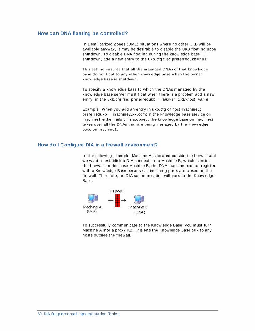
60 DIA Supplemental Implementation Topics
How can DNA floating be controlled?
In Demilitarized Zones (DMZ) situations where no other UKB will be available anyway, it may be desirable to disable the UKB floating upon shutdown. To disable DNA floating during the knowledge base shutdown, add a new entry to the ukb.cfg file: preferredukb=null.
This setting ensures that all the managed DNAs of that knowledge base do not float to any other knowledge base when the owner knowledge base is shutdown.
To specify a knowledge base to which the DNAs managed by the knowledge base server must float when there is a problem add a new entry in the ukb.cfg file: preferredukb = failover_UKB-host_name.
Example: When you add an entry in ukb.cfg of host machine1: preferredukb = machine2.xx.com; if the knowledge base service on machine1 either fails or is stopped, the knowledge base on machine2 takes over all the DNAs that are being managed by the knowledge base on machine1.
How do I Configure DIA in a firewall environment?
In the following example, Machine A is located outside the firewall and we want to establish a DIA connection to Machine B, which is inside the firewall. In this case Machine B, the DNA machine, cannot register with a Knowledge Base because all incoming ports are closed on the firewall. Therefore, no DIA communication will pass to the Knowledge Base.
To successfully communicate to the Knowledge Base, you must turn Machine A into a proxy KB. This lets the Knowledge Base talk to any hosts outside the firewall.
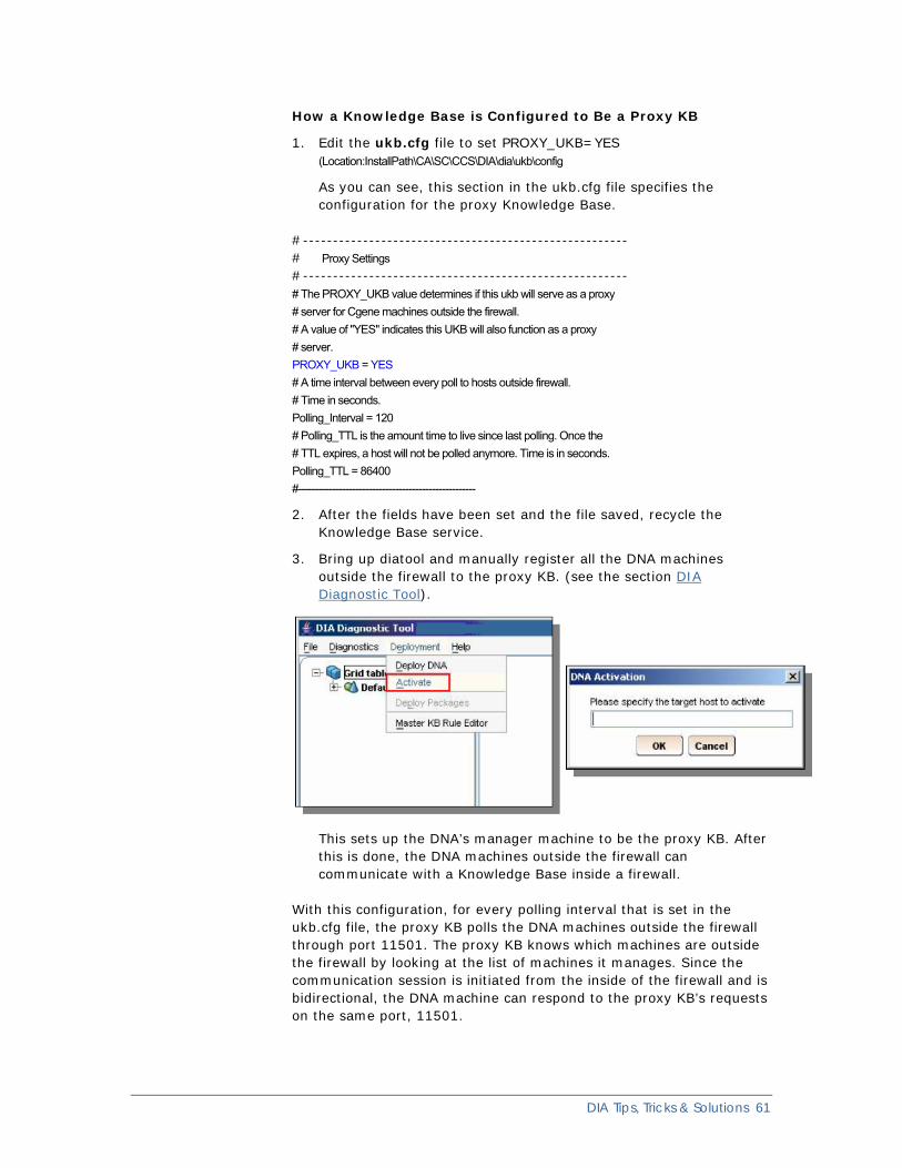
How a Knowledge Base is Configured to Be a Proxy KB
1. Edit the ukb.cfg file to set PROXY_UKB=YES (Location:InstallPath\CA\SC\CCS\DIA\dia\ukb\config
As you can see, this section in the ukb.cfg file specifies the configuration for the proxy Knowledge Base.
#------------------------------------------------------ # Proxy Settings #------------------------------------------------------ # The PROXY_UKB value determines if this ukb will serve as a proxy # server for Cgene machines outside the firewall. # A value of "YES" indicates this UKB will also function as a proxy # server. PROXY_UKB = YES # A time interval between every poll to hosts outside firewall. # Time in seconds. Polling_Interval = 120 # Polling_TTL is the amount time to live since last polling. Once the # TTL expires, a host will not be polled anymore. Time is in seconds. Polling_TTL = 86400 #-----------------------------------------------------
2. After the fields have been set and the file saved, recycle the Knowledge Base service.
3. Bring up diatool and manually register all the DNA machines outside the firewall to the proxy KB. (see the section DIA Diagnostic Tool).
This sets up the DNA’s manager machine to be the proxy KB. After this is done, the DNA machines outside the firewall can communicate with a Knowledge Base inside a firewall.
With this configuration, for every polling interval that is set in the ukb.cfg file, the proxy KB polls the DNA machines outside the firewall through port 11501. The proxy KB knows which machines are outside the firewall by looking at the list of machines it manages. Since the communication session is initiated from the inside of the firewall and is bidirectional, the DNA machine can respond to the proxy KB’s requests on the same port, 11501.
DIA Tips, Tricks & Solutions 61
62 DIA Supplemental Implementation Topics
Note: DIA uses additional ports, and these ports are configurable. For more information see the “DIA Reference” in the CA NSM Implementation Guide.
How do I configure DIA for debugging?
Update the Log_Level option to ALL in the following files: Installpath\SC\CCS\DIA\dia\ukb\config\ukb.cfg Installpath\SC\CCS\DIA\dia\dna\config\dna.cfg
For example: #---------------------------------------------------------------- # Define the logger properties *-------------------------------------------------------
# The log level could be any one of the following: OFF|SEVERE|WARNING|INFO|CONFIG|FINE|FINER|FINEST|ALL LOG_LEVEL = ALL
How do I verify that the SRV Record exists?
To determine if the DIA srv record has been set up in an environment, do the following.
1. Verify that SRV records are set up in DNS by using the following commands:
c:\>nslookup >set type=SRV >_grid._tcp _grid._tcp.ca.com SRV service location:
priority = 2 weight = 0 port = 11503 svr hostname = MasterKB_Box1.ca.com
For guidance on setting up DIA in your DNS, see the “DIA Reference” appendix in the CA NSM Implementation Guide.
What is a Master UKB and do I need it?
The single goal of the Master UKB (Master KB) is to police the DIA traffic for all the UKBs.
DNA activation is not performed against the Master KB, but against one of the UKBs, as instructed by the Master KB. The Master KB is, therefore, not a formal requirement for DNA activation.
However, using Master KB activation rules you can completely control the DNA to UKB mapping.
The independent DIA zones are also controlled by the Master KB zone rules (different from the activation rules mentioned above).
Although multiple DNS records could be created for Master KBs, there can be only two Master KBs, one primary, and one secondary. And although they are both running (normally), only one is active at a time. The secondary UKB will become active only if the primary fails.
What needs to be done to allow an r11.1 DNA to communicate with an r11.2 UKB?
To allow CA NSM r11.1 DNAs (agent nodes) to communicate with CA NSM r11.2 UKBs (manager nodes), you must install a fix on all of your CA NSM r11.2 UKB nodes. This fix is required only if CA NSM r11.1 DNAs will be reregistering (reactivating) with CA NSM r11.2 UKBs or if there will be new CA NSM r11.1 DNA-only (that is, agent-only) installations. Please contact Technical Support at https://support.ca.com for the required fix and notify them of your CA NSM r11.2 UKB platforms.
Note: For more information and facts to consider when migrating to CA NSM r11.2, see the CA NSM Migration Guide, which is available with the product documentation.
What should I do if I have a connection problem between my MasterKB and KB, or the KB and DNA (Activation)?
First check the network settings and verify that all host machines are able to resolve by doing nslookup or even pinging. If this is an activation issue relating to an agent-only installation, check the SRV record, xml rule file, or network settings.
Why do I get DIA error messages when my MCC client starts up?
On an agent-only installation, MCC gets a DIA internal error message during startup. The workaround is to create the directory \dia\ukb\config and copy a ukb.cfg into this directory and restart the MCC. This problem is resolved in both CA NSM r11.1 and r11.2.
DIA Tips, Tricks & Solutions 63
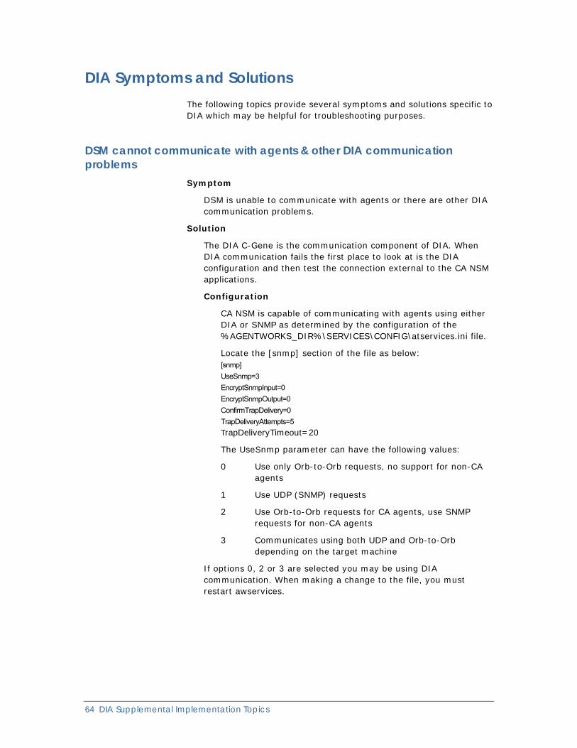
64 DIA Supplemental Implementation Topics
DIA Symptoms and Solutions The following topics provide several symptoms and solutions specific to DIA which may be helpful for troubleshooting purposes.
DSM cannot communicate with agents & other DIA communication problems
Symptom
DSM is unable to communicate with agents or there are other DIA communication problems.
Solution
The DIA C-Gene is the communication component of DIA. When DIA communication fails the first place to look at is the DIA configuration and then test the connection external to the CA NSM applications.
Configuration
CA NSM is capable of communicating with agents using either DIA or SNMP as determined by the configuration of the %AGENTWORKS_DIR%\SERVICES\CONFIG\atservices.ini file.
Locate the [snmp] section of the file as below: [snmp] UseSnmp=3 EncryptSnmpInput=0 EncryptSnmpOutput=0 ConfirmTrapDelivery=0 TrapDeliveryAttempts=5 TrapDeliveryTimeout=20
The UseSnmp parameter can have the following values:
0 Use only Orb-to-Orb requests, no support for non-CA agents
1 Use UDP (SNMP) requests
2 Use Orb-to-Orb requests for CA agents, use SNMP requests for non-CA agents
3 Communicates using both UDP and Orb-to-Orb depending on the target machine
If options 0, 2 or 3 are selected you may be using DIA communication. When making a change to the file, you must restart awservices.
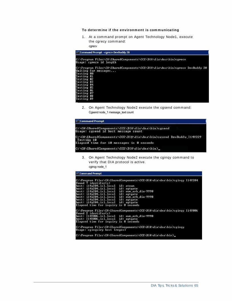
To determine if the environment is communicating
1. At a command prompt on Agent Technology Node1, execute the cgrecy command: cgrecv
2. On Agent Technology Node2 execute the cgsend command: Cgsend node_1 message_text count
3. On Agent Technology Node2 execute the cginqy command to verify that DIA protocol is active. cginqy node_1
DIA Tips, Tricks & Solutions 65
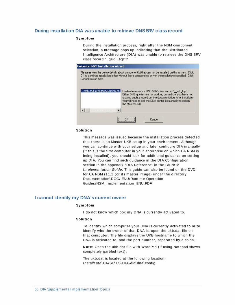
66 DIA Supplemental Implementation Topics
During installation DIA was unable to retrieve DNS SRV class record Symptom
During the installation process, right after the NSM component selection, a message pops up indicating that the Distributed Intelligence Architecture (DIA) was unable to retrieve the DNS SRV class record “_grid._tcp”?
Solution
This message was issued because the installation process detected that there is no Master UKB setup in your environment. Although you can continue with your setup and later configure DIA manually (if this is the first computer in your enterprise on which CA NSM is being installed), you should look for additional guidance on setting up DIA. You can find such guidance in the DIA Configuration section in the appendix “DIA Reference” in the CA NSM Implementation Guide. This guide can also be found on the DVD for CA NSM r11.2 (or its master image) under the directory Documentation\DOC\ ENU\Runtime Operation Guides\NSM_Implementation_ENU.PDF.
I cannot identify my DNA’s current owner Symptom
I do not know which box my DNA is currently activated to.
Solution
To identify which computer your DNA is currently activated to or to identify who the owner of that DNA is, open the ukb.dat file on that computer. The file displays the UKB hostname to which the DNA is activated to, and the port number, separated by a colon.
Note: Open the ukb.dat file with WordPad (if using Notepad shows completely garbled text).
The ukb.dat is located at the following location: InstallPath\CA\SC\CS\DIA\dia\dna\config.
Glossary
activation Activation is a form of DIA communication, which is based on Java RMI and by default it is not encrypted. The existing zone policy file determines and controls the activation information.
c gene technology C Gene technology is responsible for moving data between hosts. It can perform tasks such as changing network IP addresses, detecting firewalls, and issuing proxy requests to the Knowledge Base for systems that are unreachable through normal communications. As with all DIA technology, C Gene technology performs independent of user interaction, on demand, and dynamically enough to be self-maintaining.
cells Cells are the primary mechanisms for acting on existing data. They are data- or command-specific modules that collect any type of information from any given type of data source and therefore are responsible for the knowledge of the abstracted entities on which they are instructed to operate. Cells plug directly into the gene interface to collect data and are responsible for any type of communication needed for the data manipulation they support.
demilitarized zone (DMZ) The demilitarized zone (DMZ) is a firewall configuration for securing local area networks (LANs).
Distributed Intelligence Architecture (DIA) Distributed Intelligence Architecture (DIA) allows a central location to manage all components and aspects of a network. DIA makes data requests and retrievals standard across different CA NSM components by providing a generic mechanism that permits the dynamic deployment of necessary files to facilitate the correct monitoring of any given system. DIA serves as the common communication and data collection interface that monitors your entire system.
DIA configuration DIA Configuration is an important process to perform so that the DIA is configured to monitor your infrastructure:
■ Configure Knowledge Base policy file
■ Create DIA rules file
Glossary 67
68 DIA Supplemental Implementation Topics
DIA encryption DIA Encryption enhances data transfer security. All host level outbound data communications that include those from DIA components (Dynamic Node Administrator or Knowledge Base) are able to use secure sockets and can be configured to use public and private key encryption. By default, DIA communication is not encrypted, but it can be configured for encryption with the creation of an encryption key.
DIA grid The DIA grid determines the network location of particular DIA system elements. The grid allows users to route requests to any computers in the current DIA architecture. Users can make requests to any Unicenter Knowledge Base in the system and the grid will route it correctly for data retrieval.
DIA Diagnostic Tool (DIA Tool) The DIA Diagnostic Tool is a component of CA NSM that lets you troubleshoot and manage all aspects of your DIA infrastructure from any Knowledge Base. The DIA Diagnostic Tool is installed as part of the Knowledge Base installation and is located at: (Windows) InstallPath\CA\SC\CCS\DIA\dia\ukb\bin\diatool.bat (UNIX) $CA_DIA_HOME/dia/ukb/bin/diatool.bat.
Dynamic Node Administrator (DNA) The Dynamic Node Administrator detects operating system information, software and hardware information, and network information pertaining to the given target host. This information is then transmitted back to the Knowledge Base to determine the best way to manage the system and what components the system needs.
failover Failover is an important fault-tolerant function of mission-critical systems that demand constant availability. Failover is a backup operation in which the functions of a system component (such as a processor, server, network, or database) automatically and transparently switch to secondary system components when the primary component becomes unavailable through either failure or scheduled down time.
failback Failback is the process of migrating a failed application back to its original node to rebalance workloads when a previously failed component is available again.
gene The gene is an interface between the cells and the Dynamic Node Administrator. The gene is responsible for the following:
■ Cell inventory
■ Encryption and decryption
■ Work order acceptance
grid synchronization Grid synchronization is a component of DIA Communication and is based on Java RMI, and by default this information is not encrypted. It is the second task performed after the Knowledge Base starts, looks for the presence of the SRV record, and then contacts that Knowledge Base.
HACMP HACMP is a type of vendor cluster supported by HAS (High Availability Service) and stands for IBM High Availability Cluster Multiprocessing for AIX (HACMP). Using HAS, applications are automatically registered, which lets them receive status and notifications. Once registered, an application can be failed over (migrated) to another node on the cluster, ensuring continuous service.
L gene technology L Gene technology is used by DIA to convert back-end data into an abstract format that can be distributed across the system for the purpose of displaying or correlating the data. L Genes provide a clean and easy to use interface for data suppliers to connect to DIA and feed knowledge into the system. DIA uses the L Gene to start up and configure a collection of cells that are used to cultivate or obtain knowledge from any given system. L Cells serve as the hook into DIA, and L Genes determine if a given L Cell should be created on a system based on information found on the given system.
management aware/enabled Management Aware/Enable is a task that is performed by Dynamic Node Administrator which activates components for cultivating knowledge from the target system for display in a GUI.
Master Knowledge Base (MasterKB, MKB) A Master Knowledge Base handles initial requests from newly installed CA NSM components. It contains a list of all the other KBs that exist and is responsible for segmenting them into appropriate zones according to the rules defined in the DIA Rules file. The Master Knowledge Base is the keeper of the grid information. The Master Knowledge Base coordinates and updates changes to all Knowledge Bases in the zones.
match cases Each rule has match cases and an Otherwise match case associated with it. The match case defines the criteria for assigning zone or ownership. The match can be based on IP address or host name.
owner The owner defines the Dynamic Node Administrator ownership, or which DNA computer must be managed (or owned) by which Knowledge Base host (the activation rule)
Glossary 69
70 DIA Supplemental Implementation Topics
SRV Record, Service Location Record Service Location Record, or SRV Record, a resource record dialog that provides a user interface to set the values for the domain, service, protocol, priority, weight, port number, and the host (DNS server) offering the service. The auto detection mechanism uses Domain Name Services (DNS) SRV records to locate the Knowledge Bases that activate and use DIA.
Unicenter Knowledge Base The Unicenter Knowledge Base is the central communication and management point for DIA, serving as the interface for the outside world in the DIA system. A Knowledge Base consists of a core, a Dynamic Node Administrator interface, a consumer interface, and a plug-in interface. It is a logical grouping of Dynamic Node Administrator hosts that collects data from several sources and abstracts the original location of the information.
zones Zones are logical entities or groupings of managed hosts on the network. Zone information is based on policy on the Master Knowledge Bases and is used to segregate groupings of computers so that there is no communication between logical groupings.
Index A activation • 47
verifying • 20 agent
floating • 56 installation • 54 not discovered pingagt • 46 upgrade • 47
alert cells • 30 atservices • 64
B best practices
DIA installation • 11 encryption • 52
C cgene • 64 cgrecy command • 65 cgsend command • 65 cluster
activation • 47 DIA setup • 48 failover • 50 Master KB • 48 Master KB configuration • 48
components using DIA • 26 configuring
DIA encryption • 23 DNA • 23 UKB • 24
D deactivation • 47 default directories • 9 DIA
AIX errors • 57 alert and event cells • 31 cluster setup • 48 communication • 64 consumers • 52 encrypted • 23, 52 handling large deployments • 12 important points • 50 Master KB on Cluster • 48
node management • 33 operational tips • 38 ports • 29 push model • 30 recycle services • 31 rule editor • 33 services • 23, 50 tips and tricks • 45 utilities • 39 versions • 8
DIA Tool • 19 deactivation • 47 log in failure • 58 Pure IPv6 • 57
DIA utilities getMasterKB • 39 getOwnerKB • 39 getSRVInfo • 40 getZone • 41 refreshZone • 40
directory structure • 8 DNA
activation • 47 autoactivate • 38 child nodes • 54 configuration • 23 configuration file • 50 current owner • 66 floating • 59 Knowledge Base • 60 mapping • 12 moving zones • 59 ownership • 33, 66 performance • 12 ports • 29 utilities • 41
DNA utilities GetCellInfo • 42 GetRegisteredCells • 41 setLogLevel • 42 updateConfigFile • 43
DNS SRV class record • 66 DNS SRV record • 48 domain change • 50 dual stack • 56
Index 71
72 DIA Supplemental Implementation Topics
E encrypted
DIA • 52 environment • 51 manager • 51
encryption configuring • 23 key, creating • 24
event cells • 30
F firewalls • 13, 52
UKB to DNA • 30 UKB to UKB • 30
floating • 59
G GetCellInfo • 42 getMasterKB • 39 getOwnerKB • 39 GetRegisteredCells • 41 getSRVInfo • 40 getZone • 41
H HACMP • 13 highly available • 48
I installation
agent only • 54 JRE not found • 58 manager • 54 prerequisite • 11 problem • 66
IPv6 agent floating • 56 DIA Tool • 57 link local addresses • 55 mixed environment • 56 prerequisite • 55
J JRE versions • 8
K keytool utility • 24 Knowledge Base • 34
Master • 34, 62 primary • 50 secondary • 50
L logLevel • 42
M Management Command Center
port range • 30 manager installation • 54 Master Knowledge Base • 34, 62
encrypted • 51 moving • 55 overload • 56
match cases • 33 Otherwise option • 34, 38 update • 36 zone rule • 37
mode_value • 40
N NAT environments • 14
O online documentation • 7 Orb-to-Orb requests • 64 Otherwise match case • 38 overrideSRV option • 48, 57 owner
DNA • 33, 66 rule node • 36
P patches required • 27 physical names • 50 pingagt • 46 ports
DIA • 29 DNA • 29 UKB • 30
preferredUKB • 50 prerequisites
installation • 11 IPv6 • 55
primary and secondary KBs • 50 primary knowledge base, cluster • 49, 50 ProxyUKB • 20
R recommended reading • 8 refreshZone • 40 RMI Binding
enabling override • 14 rule editor • 33
insertion location • 37
Index 73
rules evaluation • 57 sample file • 35
S secondary KB,take over • 50 setLogLevel • 42 SRV class record • 66 Support Online • 8
T technical support • 9 tips and tricks • 45
U UKB
configuration • 24 ports • 30 Proxy • 29
Unicenter Management Portal • 30 DNA • 32 port range • 31
UNIX DIA errors • 57 DIA Tool errors • 57 JRE not found • 58 Log in failure • 58 multiple domains • 59
updateConfigFile • 43 UseSnmp • 53, 64 utilities
DNA • 41 Knowledge Base • 39
V VNode • 54
Z zone • 33
demilitarized • 60 infraction error • 58 moving DNA • 59 name • 35 update • 59