Embed Size (px)
Citation preview

Interfaces Guide Release 12.7
CA JARS® Resource Accounting

This Documentation, which includes embedded help systems and electronically distributed materials, (hereinafter referred to as the “Documentation”) is for your informational purposes only and is subject to change or withdrawal by CA at any time.
This Documentation may not be copied, transferred, reproduced, disclosed, modified or duplicated, in whole or in part, without the prior written consent of CA. This Documentation is confidential and proprietary information of CA and may not be disclosed by you or used for any purpose other than as may be permitted in (i) a separate agreement between you and CA governing your use of the CA software to which the Documentation relates; or (ii) a separate confidentiality agreement between you and CA.
Notwithstanding the foregoing, if you are a licensed user of the software product(s) addressed in the Documentation, you may print or otherwise make available a reasonable number of copies of the Documentation for internal use by you and your employees in connection with that software, provided that all CA copyright notices and legends are affixed to each reproduced copy.
The right to print or otherwise make available copies of the Documentation is limited to the period during which the applicable license for such software remains in full force and effect. Should the license terminate for any reason, it is your responsibility to certify in writing to CA that all copies and partial copies of the Documentation have been returned to CA or destroyed.
TO THE EXTENT PERMITTED BY APPLICABLE LAW, CA PROVIDES THIS DOCUMENTATION “AS IS” WITHOUT WARRANTY OF ANY KIND, INCLUDING WITHOUT LIMITATION, ANY IMPLIED WARRANTIES OF MERCHANTABILITY, FITNESS FOR A PARTICULAR PURPOSE, OR NONINFRINGEMENT. IN NO EVENT WILL CA BE LIABLE TO YOU OR ANY THIRD PARTY FOR ANY LOSS OR DAMAGE, DIRECT OR INDIRECT, FROM THE USE OF THIS DOCUMENTATION, INCLUDING WITHOUT LIMITATION, LOST PROFITS, LOST INVESTMENT, BUSINESS INTERRUPTION, GOODWILL, OR LOST DATA, EVEN IF CA IS EXPRESSLY ADVISED IN ADVANCE OF THE POSSIBILITY OF SUCH LOSS OR DAMAGE.
The use of any software product referenced in the Documentation is governed by the applicable license agreement and such license agreement is not modified in any way by the terms of this notice.
The manufacturer of this Documentation is CA.
Provided with “Restricted Rights.” Use, duplication or disclosure by the United States Government is subject to the restrictions set forth in FAR Sections 12.212, 52.227-14, and 52.227-19(c)(1) - (2) and DFARS Section 252.227-7014(b)(3), as applicable, or their successors.
Copyright © 2012 CA. All rights reserved. All trademarks, trade names, service marks, and logos referenced herein belong to their respective companies.

CA Technologies Product References
This document references the following CA products:
■ CA ACF2™ for z/OS
■ CA Auditor for z/OS
■ CA Common Services for z/OS
■ CA MICS® Resource Management
■ CA Service Desk
■ CA SMF Director®
■ CA Top Secret® for z/OS

Documentation Changes
The following documentation updates have been made since the last release of this documentation:
Note: In PDF format, page references identify the first page of the topic in which a change was made. The actual change may appear on a later page.
■ Updated The DB2 Interface (see page 89) section.
Contact CA Technologies
Contact CA Support
For your convenience, CA Technologies provides one site where you can access the information that you need for your Home Office, Small Business, and Enterprise CA Technologies products. At http://ca.com/support, you can access the following resources:
■ Online and telephone contact information for technical assistance and customer services
■ Information about user communities and forums
■ Product and documentation downloads
■ CA Support policies and guidelines
■ Other helpful resources appropriate for your product
Providing Feedback About Product Documentation
If you have comments or questions about CA Technologies product documentation, you can send a message to [email protected].
To provide feedback about CA Technologies product documentation, complete our short customer survey which is available on the CA Support website at http://ca.com/docs.

Contents 5
Contents
Chapter 1: The ADABAS Interface 11
User Tables ................................................................................................................................................................. 11
Environment Table .............................................................................................................................................. 11
CPU Table ............................................................................................................................................................ 12
Account Code Table ............................................................................................................................................ 12
Record Descriptions and Processing Rules ................................................................................................................. 13
ADABAS Command Log Record Description ....................................................................................................... 13
CA JARS Data Element Assignments for ADABAS ................................................................................................ 15
Operating Instructions ............................................................................................................................................... 17
User Table Customization ................................................................................................................................... 17
Operations .......................................................................................................................................................... 23
The ADABAS Interface User Exit Routine ................................................................................................................... 31
Sample Reports .......................................................................................................................................................... 36
ADABAS Interface Reports .................................................................................................................................. 36
CA JARS Reports .................................................................................................................................................. 39
EXTDATA Reports ................................................................................................................................................ 46
Reporting Considerations ........................................................................................................................................... 49
ADABAS Data Elements ....................................................................................................................................... 50
ADABAS Basic Accounting Table ......................................................................................................................... 50
Contents of Target Libraries ....................................................................................................................................... 52
Chapter 2: The Interface to CA Datacom/DB 55
Benefits of the Interface to CA Datacom/DB ............................................................................................................. 56
Input and Output ........................................................................................................................................................ 56
Cost Center Identification .......................................................................................................................................... 56
The Interface to CA Datacom/DB Components ......................................................................................................... 57
System Requirements ................................................................................................................................................ 57
Creating the Summary File ......................................................................................................................................... 58
The Translate Component ................................................................................................................................... 58
Preparing Translate Control Statements ............................................................................................................. 59
Creating a User Accounting Table ....................................................................................................................... 61
Operations .......................................................................................................................................................... 64
Record Descriptions and Processing Rules ................................................................................................................. 70
Accounting Table Record Description ................................................................................................................. 70
Data Element Assignments for CA Datacom/DB ................................................................................................. 71
Sample Reports .......................................................................................................................................................... 73

6 Interfaces Guide
CA Datacom/DB Interface Reports...................................................................................................................... 73
CA JARS Reports .................................................................................................................................................. 75
EXTDATA Reports ................................................................................................................................................ 81
Reporting Considerations ........................................................................................................................................... 83
CA Datacom/DB Data Elements .......................................................................................................................... 84
Basic Accounting Table........................................................................................................................................ 84
Contents of Target Libraries ....................................................................................................................................... 86
Chapter 3: The DB2 Interface 89
Distributed Sample Source Code ................................................................................................................................ 90
JARSDB21: Debit Record Creation .............................................................................................................................. 90
JARSDB21 Control Statements ............................................................................................................................ 93
JARSDB21 Execution Description ........................................................................................................................ 94
JARSDB22: Sample Report .......................................................................................................................................... 97
JARSDB22 Control Statements ............................................................................................................................ 98
JARSDB22 Execution Description ........................................................................................................................ 98
Chapter 4: The IMS Interface 101
21st Century Support ............................................................................................................................................... 102
Sorting on Date Fields ....................................................................................................................................... 102
Selection, Rejection, and Compares Involving Date Fields ............................................................................... 103
Grouping ........................................................................................................................................................... 103
Calculations Involving Date Fields ..................................................................................................................... 103
Interface Components .............................................................................................................................................. 104
User Accounting Table ...................................................................................................................................... 104
User Accounting Table Macro ........................................................................................................................... 104
The User Accounting Table....................................................................................................................................... 105
Creating a User Accounting Table ..................................................................................................................... 106
Initializing the User Accounting Table ............................................................................................................... 107
Defining a User Accounting Table Cost Center Entry ........................................................................................ 108
Terminating a User Accounting Table ............................................................................................................... 108
Interface Operation .................................................................................................................................................. 109
Interface Commands ................................................................................................................................................ 112
Interface Command Format .............................................................................................................................. 112
COMPRESS Command ....................................................................................................................................... 113
DEFAULT Command .......................................................................................................................................... 115
FFGRAPH Command .......................................................................................................................................... 115
Examples ........................................................................................................................................................... 123
SYSPLOT Report Codes ...................................................................................................................................... 124
SUBSET Index Identifiers ................................................................................................................................... 125
FFGRAPH Keyword Title and Label Defaults ..................................................................................................... 126

Contents 7
TRANSLATE Command ...................................................................................................................................... 133
Sample Resource Utilization Graphs Examples ................................................................................................. 135
The Wizard Report Writer ........................................................................................................................................ 146
Output ............................................................................................................................................................... 146
Executing the Wizard Report Writer ........................................................................................................................ 148
Data Set Use ...................................................................................................................................................... 148
Concatenating Input Files.................................................................................................................................. 150
Sample JCL ......................................................................................................................................................... 150
Control Statements ........................................................................................................................................... 151
Data Element Directory ............................................................................................................................................ 174
Summary Record Format .................................................................................................................................. 174
CA JARS IMS Basic Accounting Table ................................................................................................................. 176
CA JARS IMS Output Data Elements Table ........................................................................................................ 179
Chapter 5: The Network Accounting Interface 183
Daily Processing for CA Mazdamon .......................................................................................................................... 183
Daily Processing for IBM NETVIEW .......................................................................................................................... 183
Operating Instructions ............................................................................................................................................. 184
Sample Report - JSINET1 .......................................................................................................................................... 187
JSINET1 Execution Description .......................................................................................................................... 189
Sample Report - JSINET2 .......................................................................................................................................... 192
JSINET2 Execution Description .......................................................................................................................... 194
CA Mazdamon and IBM NETVIEW Data Elements ................................................................................................... 195
EXTDATA Reports ..................................................................................................................................................... 197
Chapter 6: The CA Roscoe Interface 203
Functional Description ............................................................................................................................................. 203
Roscoe Journal File ................................................................................................................................................... 204
Roscoe Sign-off Record Layout Pre Roscoe Release 5.5.................................................................................... 204
Roscoe Record Layout for Roscoe 5.5 and Above ............................................................................................. 205
Roscoe Data Element Assignments ................................................................................................................... 207
Operating Instructions ............................................................................................................................................. 210
Sample Reports ........................................................................................................................................................ 216
Roscoe Interface Reports .................................................................................................................................. 216
CA JARS Reports ................................................................................................................................................ 217
EXTDATA Reports .............................................................................................................................................. 230
Reporting Considerations ......................................................................................................................................... 233
Roscoe Basic Accounting Table ......................................................................................................................... 233

8 Interfaces Guide
Chapter 7: The Tape Volume Accounting Interface 237
Functional Description ............................................................................................................................................. 237
21st Century Support ............................................................................................................................................... 238
Operating Instructions ............................................................................................................................................. 238
TVA Control Statement Layout ......................................................................................................................... 238
TVA File Names ................................................................................................................................................. 239
TVA Sample JCL ................................................................................................................................................. 241
Sample Reports ........................................................................................................................................................ 242
Distributed Sample Source Code ...................................................................................................................... 242
JR70TVA1: Debit Record Creation ..................................................................................................................... 243
JR70TVA2 Report Sample .................................................................................................................................. 249
EXTDATA Reports .............................................................................................................................................. 253
TVA Data Elements ................................................................................................................................................... 257
Chapter 8: The VM Interface 259
VM Interface Components ....................................................................................................................................... 260
User Accounting Table ...................................................................................................................................... 260
User Accounting Table Macro ........................................................................................................................... 261
Sample Reports ................................................................................................................................................. 261
VM Interface Materials ..................................................................................................................................... 261
Creating and Using the Accounting Table ................................................................................................................ 261
Initiating the User Accounting Table ................................................................................................................. 263
Defining the User Accounting Table Entry ........................................................................................................ 263
Terminating the User Accounting Table............................................................................................................ 264
User Accounting Table Entries Examples .......................................................................................................... 264
Creating a User Accounting Table ..................................................................................................................... 265
The Translate Component ........................................................................................................................................ 267
Translate Component Control Statements ....................................................................................................... 267
Reporting Component .............................................................................................................................................. 268
VM Accounting Record...................................................................................................................................... 269
User-Defined Reports ........................................................................................................................................ 270
Preparing Control Statements........................................................................................................................... 272
Report Control Statements ............................................................................................................................... 275
VM Tables.......................................................................................................................................................... 308
Charging For VM Resources (CMS) ................................................................................................................... 315
Charging for VM Resources (VSE) ..................................................................................................................... 320
VM Accounting Versus Batch Accounting ......................................................................................................... 326
User Exit Routines .................................................................................................................................................... 327
Account Exit ...................................................................................................................................................... 328
Exit #1 ................................................................................................................................................................ 329
Exit #2 ................................................................................................................................................................ 334
Contents 9
Exit #3 ................................................................................................................................................................ 335
Sample Reports ........................................................................................................................................................ 337
CMS Control Report .......................................................................................................................................... 337
Termination Report ........................................................................................................................................... 339
Daily I/O Activity by User .................................................................................................................................. 340
I/O Charge Detail by User.................................................................................................................................. 341
U/R And Setup Charges by User Report ............................................................................................................ 342
Processor and Connect Charge Breakdown by User and Date ......................................................................... 343
VM Total Charge Summary by User and Date ................................................................................................... 344
Tape and Disk Activity Report ........................................................................................................................... 345
Virtual Machine Paging Profile .......................................................................................................................... 346
EXTDATA Reports .............................................................................................................................................. 347
Running the VM Interface ........................................................................................................................................ 347
Transporting VM Accounting Data to a Guest System ...................................................................................... 347
Translate Execution ........................................................................................................................................... 349
Main Program Execution ................................................................................................................................... 350
Index 353

Chapter 1: The ADABAS Interface 11
Chapter 1: The ADABAS Interface
The ADABAS Interface is distributed as part of the CA JARS Resource Accounting family of programs. It provides users of Software AG's ADABAS database management package with the reporting capabilities of CA JARS. Through the use of this interface, you can use the Report Writer to report on ADABAS log records.
This section contains the following topics:
User Tables (see page 11) Record Descriptions and Processing Rules (see page 13) Operating Instructions (see page 17) The ADABAS Interface User Exit Routine (see page 31) Sample Reports (see page 36) Reporting Considerations (see page 49) Contents of Target Libraries (see page 52)
User Tables
Execution of the ADABAS Interface requires that you create, assemble, and link-edit several tables. These user tables contain specific information describing your installation. Sample user tables, that may be used as a basis for customization can be found in the CAJRSAMP library. The macros required for assembly can be found in CAJRMAC. A general description of each of these user tables is now provided.
Environment Table
The Environment Table is built by assembling and linking a set of QENVR macro statements. It defines the run time environment for the ADABAS Interface. Using this table you specify:
■ the data elements on which you wish to have the ADABAS log records sorted and summarized
■ the job name(s) for the teleprocessing monitors used at your installation(s) to distinguish online and batch usage
■ the default format buffer length needed to compute the estimated CPU time.

User Tables
12 Interfaces Guide
CPU Table
The CPU Table lists the instruction speed of several CPUs from various manufacturers. The interface uses the CPU instruction speed to compute the estimated CPU time according to formulas described in Software AG's SAGTIP009.
The CPU Table is built by assembling and linking a set of QCPU macro statements.
Each entry in the CPU Table is also assigned:
■ an installation correction factor that you compute.
■ a one-character CPU ID that you specify at run time via CAIJRIN to select a predetermined entry from this table. This CPU ID mechanism allows you to process ADABAS data from several CPUs through multiple runs of the interface without reassembling the CPU Table.
Account Code Table
The Account Code Table gives you the ability to assign account codes to combinations of job names and user IDs.
The Account Code Table is built by assembling and linking a set of QAACT macro statements.
The ADABAS Interface scans the Account Code Table for an entry whose job name and user ID match an ADABAS log record's job name and user ID. Each Account Code Table entry is compared character-by-character. An asterisk (*) in any position of the job name or user ID forces the remaining characters of the job name and/or user ID to be treated as a match. The account code from the first entry to match the log record is inserted into the CA JARS output record. If no match is found, the output account code is left blank.

Record Descriptions and Processing Rules
Chapter 1: The ADABAS Interface 13
Record Descriptions and Processing Rules
ADABAS Command Log Record Description
The following table describes the ADABAS Version 5 command log record. The corresponding DSECT can be found in CAJRSAMP member ADAEXIT. The ADABAS Interface can also process Version 4 command log records. When Version 4 command log records are encountered, they are internally converted to the Version 5 format.
ADABAS Command Log Record Layout:
Field Name Field Position
Field Length
F* Description
LOGRTYPE 1 2 b Record Type
LOGVER 3 2 a Log Version c'52'
LOGTIMI 5 8 b Time Command Completed
LOGBUFT 13 1 b Buffer Type
LOGPRTY 14 1 b OS Dispatching Priority
LOGCTYPE 15 1 b Command Type
LOGNECBS 16 1 b Number of posted ECB's
LOGTHDNR 17 1 b Thread Number
LOGBFLAG 18 1 b User Buffer Flag
LOGNUPDS 19 2 b Descriptors Updated
LOGJNAME 21 8 a Job Name
LOGCPUID 29 8 b Hex CPU ID
LOGVMJD 37 8 b VM ID
LOGOSJD 45 4 b OS ID
LOGUSER 49 8 a User ID
LOGDUR 57 4 b Duration, in units of 16 microseconds
LOSSEQNO 61 4 b Command Sequence number
LOSDBID 65 2 b Database ID
LOGASSOI 67 2 b No. Associator I/Os
LOGDATAI 69 2 b No. Data I/Os

Record Descriptions and Processing Rules
14 Interfaces Guide
Field Name Field Position
Field Length
F* Description
LOGWORKI 71 2 b No. Work I/Os
LOGSIBAI 73 2 b No. Siba I/Os
LOGARCH 75 1 b Architecture Type
RESERVED 76 3 b Reserved
79 2 b Slack Byte
LOGREV 81 4 b Review
LOGNUCID 85 2 b SMP/ADAPLEX NUC ID
RESERVED 87 2 b Reserved
RESERVED 89 2 a Reserved
LOGCMD 91 2 a Command Code
LOGCID 93 4 a Command ID
LOGFNR 97 2 b File Number
LOGRSP 99 2 b Response Code
LOGISN 101 4 b Internal Sequence Number
LOGISL 105 4 b ISN Lower Limit
LOGISQ 109 4 b ISN Quantity
LOGFBL 113 2 b Format Buffer Length
LOGRBL 115 2 b Record Buffer Length
LOGSBL 117 2 b Search Buffer Length
LOGVBL 119 2 b Value Buffer Length
LOGIBL 121 2 b ISN Buffer Length
LOGOP1C 123 1 c Command Options 1
LOGOP2C 124 1 c Command Options 2
LOGAD1 125 8 c Additions 1 Field
LOGAD2C 133 4 c Additions 2 Field
LOGAD3 137 8 c Additions 3 Field
LOGAD4 145 8 c Additions 4 Field
LOGAD5 153 8 a Additions 5 Field
LOGCMTM 161 4 b Command Time

Record Descriptions and Processing Rules
Chapter 1: The ADABAS Interface 15
Field Name Field Position
Field Length
F* Description
LOGUSFLD 165 4 b User Field
Format Indicator a=alphameric b=binary c=character
CA JARS Data Element Assignments for ADABAS
The following table associates a processing rule with each of the fields in the CA JARS record supplied by the ADABAS Interface.
Processing rule IDs (column 3) are described on the next page.
CA JARS Data Element Assignments For ADABAS Data:
CA JARS Element Source ADA/Literal Processing Rule ID
CPU ID 'S' 9
File ID '7' 9
Reader Start Date LOGTIMI-LOGDUR 2
Reader Start Time LOGTIMI-LOGDUR 2
Job Name LOGJNAME 1
Job/Step Ind '11' 9
Step Number 3
Processing ID 'C' 9
Record ID '*ADABAS*' 9
Start Time LOGTIMI-LOGDUR 2
Start Date LOGTIMI-LOGDUR 2
Job Class LOGCMD 1
Stop Time LOGTIMI 4
Programmer Name LOGPHUID+LOGJNAME+LOGCMD 5
Step Name LOGPHUID 1
Program Name LOGCMD+LOGFNR 5
Elapsed Time LOGDUR 6
Estimated CPU Time 7
Rdr I/O Count LOGASSOI 10

Record Descriptions and Processing Rules
16 Interfaces Guide
CA JARS Element Source ADA/Literal Processing Rule ID
Prt I/O Count LOGWORKI 10
Other I/O Count LOGDATAI 10
Total I/O Count LOGASSOI+LOGWORKI+LOGDAT 10
Day of Week Code LOGTIMI-LOGDUR 8
Reserved Field 1 'YNNNNN' 9
Processing Rules
1. Straight Move: For character fields, left-justified if possible, low-order character truncation of blank filling; for numeric field, type conversion is permitted; high-order digit truncation may be possible but is considered unlikely; scale must not change.
2. Derive date and time from STCK start time. Keep the minimum start date and time from the log records that created the summary record.
3. Number of log records that created the summary record.
4. Derive the date and time from STCK end time. Keep the maximum end time from the log records that created the summary record.
5. Concatenate items with dashes.
6. Convert units in 16 microseconds to JARS MINUTES, DEC=5.
7. Compute estimated CPU time according to the formulas described in SAGTIP009.
8. Derive day of week code from result of rule 2.
9. Constant
10. Accumulated according to user-specified keys in QENVR table.
Estimated CPU Time
The calculation of estimated CPU time is represented by instruction path counts within ADABAS commands and the executing CPU instruction execution, per second, factored by the ADABAS job CPU time as logged by SMF.
The estimated CPU time element is approximated by the interface as documented by Software AG's SAGTIP009. Its accuracy ultimately depends on:
1. The reliability of the user-supplied factors.
2. The stability of ADABAS itself. (As enhancements are made to ADABAS, the instruction paths change.)

Operating Instructions
Chapter 1: The ADABAS Interface 17
Operating Instructions
User Table Customization
You must supply installation-specific information to the ADABAS Interface through user tables. The Environment and CPU Tables are required; the Account Code Table is optional. Each table corresponds to a set of QENVR, QCPU, or QAACT macro statements. These are described in this section.
Sample user tables, which may be used as a starting point for your installation, can be found in CAJRSAMP. These should be modified to suit your needs and assembled with //SYSLIB pointing or concatenated to CAJRMAC. At linkage editor time, the ENTRY and NAME statements should be used with the appropriate table. For example:
ENTRY JSIQENVR
NAME QENVR(R)
These statements should be used to link QENVR. User table load modules must reside in one of the following libraries:
■ SYS1.LINKLIB
■ the library in which the ADABAS Interface resides (that is, STEPLIB)
■ a library concatenated to the library corresponding to STEPLIB for ADABAS Interface processing
Note: The load library contains user tables that are meaningful only for the Installation Verification Procedure.
QENVR Environment Macro
Macro Operands
name QENVR KEYS=(element name,...,...)
[,DEFFBL=-nn|50-]
[,TPNAMES=(name,...,...)]
name
is the name of the generated CSECT. The default name is JSIQENVR.
KEYS=
specifies, in a sublist, the element names on which the ADABAS log records are to be sorted and summarized. Valid element names are: JOBNAME, USERID, CMDCODE, and FILENUM.
Operating Instructions
18 Interfaces Guide
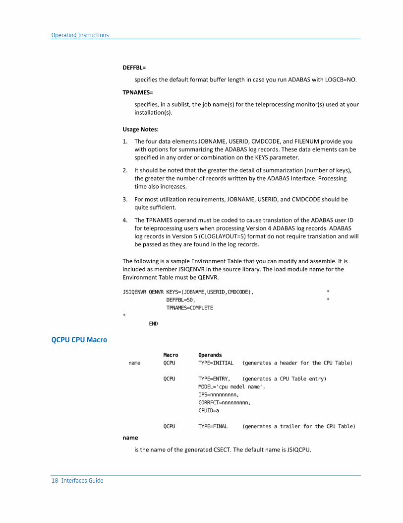
DEFFBL=
specifies the default format buffer length in case you run ADABAS with LOGCB=NO.
TPNAMES=
specifies, in a sublist, the job name(s) for the teleprocessing monitor(s) used at your installation(s).
Usage Notes:
1. The four data elements JOBNAME, USERID, CMDCODE, and FILENUM provide you with options for summarizing the ADABAS log records. These data elements can be specified in any order or combination on the KEYS parameter.
2. It should be noted that the greater the detail of summarization (number of keys), the greater the number of records written by the ADABAS Interface. Processing time also increases.
3. For most utilization requirements, JOBNAME, USERID, and CMDCODE should be quite sufficient.
4. The TPNAMES operand must be coded to cause translation of the ADABAS user ID for teleprocessing users when processing Version 4 ADABAS log records. ADABAS log records in Version 5 (CLOGLAYOUT=5) format do not require translation and will be passed as they are found in the log records.
The following is a sample Environment Table that you can modify and assemble. It is included as member JSIQENVR in the source library. The load module name for the Environment Table must be QENVR.
JSIQENVR QENVR KEYS=(JOBNAME,USERID,CMDCODE), *
DEFFBL=50, *
TPNAMES=COMPLETE
*
END
QCPU CPU Macro
Macro Operands
name QCPU TYPE=INITIAL (generates a header for the CPU Table)
QCPU TYPE=ENTRY, (generates a CPU Table entry)
MODEL='cpu model name',
IPS=nnnnnnnnn,
CORRFCT=nnnnnnnnn,
CPUID=a
QCPU TYPE=FINAL (generates a trailer for the CPU Table)
name
is the name of the generated CSECT. The default name is JSIQCPU.

Operating Instructions
Chapter 1: The ADABAS Interface 19
MODEL=
specifies, in a quoted string, the CPU model that this entry defines (1-16 characters alphanumeric).
IPS=
specifies this entry's instruction speed in IPS (Instructions Per Second) in decimal (1 to 9 digits).
CORRFCT=
specifies the installation correction factor (1 to 9 digits). Initially, the correction factor should be set to a value of '1'. After processing data for an entire ADABAS session, obtain the total Estimated CPU Time (ECPU) using the sample ADABAS Utilization Report as shown in Figure 1-3. The total Estimated CPU time (ECPU) in conjunction with the total CPU Time captured by SMF (SCPU) for the same ADABAS session, can be used to compute your installation correction factor (CORRFCT) as follows:
CORRFCT = CSPU / ECPU
CPUID=
specifies the assigned identifier for this entry (1 character alphanumeric).

Operating Instructions
20 Interfaces Guide
The following is a sample CPU Table that you can modify and assemble. It is included as member JSIQCPU in CAJRSAMP. The load module name for the CPU Table must be QCPU.
JSIQCPU QCPU TYPE=INITIAL
*
QCPU TYPE=ENTRY, *
MODEL='IBM 370/138', *
IPS=240000, *
CORRFCT=1, *
CPUID=1
*
QCPU TYPE=ENTRY, *
MODEL='IBM 370/148', *
IPS=500000, *
CORRFCT=1, *
CPUID=2
QCPU TYPE=ENTRY, *
MODEL='ESP-36', *
IPS=540000, *
CORRFCT=1, *
CPUID=3
*
QCPU TYPE=ENTRY, *
MODEL='ESP-41', *
IPS=750000, *
CORRFCT=1, *
CPUID=4
*
QCPU TYPE=ENTRY, *
MODEL='IBM 4341-1', *
IPS=750000, *
CORRFCT=1, *
CPUID=5
*
QCPU TYPE=ENTRY, *
MODEL='IBM 370/158-3', *
IPS=920000, *
CORRFCT=1, *
CPUID=6
*
QCPU TYPE=ENTRY, *
MODEL='IBM 3031', *
IPS=1200000, *
CORRFCT=1, *
CPUID=7
*
QCPU TYPE=ENTRY, *
MODEL='IBM 370/168-3', *

Operating Instructions
Chapter 1: The ADABAS Interface 21
IPS=2700000, *
CORRFCT=1, *
CPUID=8
*
QCPU TYPE=ENTRY, *
MODEL='IBM 3032', *
IPS=2700000, *
CORRFCT=1, *
CPUID=9
*
QCPU TYPE=ENTRY, *
MODEL='AMDAHL 470/V6', *
IPS=4000000, *
CORRFCT=1, *
CPUID=A
*
QCPU TYPE=ENTRY, *
MODEL='IBM 3033', *
IPS=4530000, *
CORRFCT=1, *
CPUID=B
*
QCPU TYPE=ENTRY, *
MODEL='AMDAHL 470/V7', *
IPS=4910000, *
CORRFCT=1, *
CPUID=C
*
*
QCPU TYPE=FINAL
END
Operating Instructions
22 Interfaces Guide
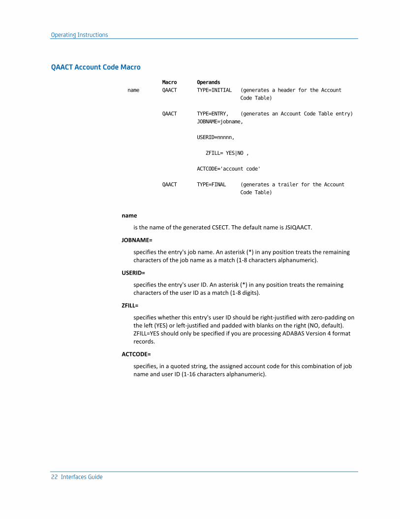
QAACT Account Code Macro
Macro Operands
name QAACT TYPE=INITIAL (generates a header for the Account
Code Table)
QAACT TYPE=ENTRY, (generates an Account Code Table entry)
JOBNAME=jobname,
USERID=nnnnn,
ZFILL= YES|NO ,
ACTCODE='account code'
QAACT TYPE=FINAL (generates a trailer for the Account
Code Table)
name
is the name of the generated CSECT. The default name is JSIQAACT.
JOBNAME=
specifies the entry's job name. An asterisk (*) in any position treats the remaining characters of the job name as a match (1-8 characters alphanumeric).
USERID=
specifies the entry's user ID. An asterisk (*) in any position treats the remaining characters of the user ID as a match (1-8 digits).
ZFILL=
specifies whether this entry's user ID should be right-justified with zero-padding on the left (YES) or left-justified and padded with blanks on the right (NO, default). ZFILL=YES should only be specified if you are processing ADABAS Version 4 format records.
ACTCODE=
specifies, in a quoted string, the assigned account code for this combination of job name and user ID (1-16 characters alphanumeric).

Operating Instructions
Chapter 1: The ADABAS Interface 23
The following is a sample Account Code Table that you can modify and assemble. It is included as member JSIQAACT in CAJRSAMP. The load module name for the Account Code Table must be QAACT.
JSIQAACT QAACT TYPE=INITIAL
*
QAACT TYPE=ENTRY, *
JOBNAME=COMPLETE, *
USERID=616, *
ZFILL=YES, *
ACTCODE='ANDRIANI'
QAACT TYPE=ENTRY, *
JOBNAME=COMPLETE, *
USERID=527, *
ZFILL=YES, *
ACTCODE='GREEN'
QAACT TYPE=ENTRY, *
JOBNAME=COMPLETE, *
USERID=604, *
ZFILL=YES, *
ACTCODE='BERGERIS'
QAACT TYPE=ENTRY, *
JOBNAME=CICS*, *
USERID=L233, *
ACTCODE='JOHNSON'
*
QAACT TYPE=FINAL
END
Operations
Execution of the ADABAS Interface requires a minimum region size of 200K. In addition, several interrelated files are also required. The following list describes these required data sets and their functions:
DDName Description
STEPLIB This statement describes the load library that was loaded from the distribution tape.
CAIJFPR This statement describes the SYSOUT data set for generated display messages.
CAIJFSN This statement describes a SYSOUT data set for generated SNAP dumps.
SYSUDUMP This statement describes a SYSOUT data set for dump output in the case of an abnormal termination.

Operating Instructions
24 Interfaces Guide
DDName Description
CAIJRADA This statement describes the ADABAS log file to be processed by the interface.
CAIJRJAR This statement describes the output file written by the interface. It is this file that is later input to the Report Writer. This file must have the following attributes:
RECFM=VB LRECL=612 BLKSIZE=6233
CAISACT This optional DD statement indicates to the interface that EXTDATA records are to be written as well. The file must have these attibutes:
RECFM=VB LRECL=8188 BLKSIZE=minimum 8192
SORTLIB This statement describes the load library that contains the installation's SORT modules.
SORTMSG This statement describes the SYSOUT data set for generated SORT messages.
SORTWKnn These statements describe the temporary data sets used as sort work areas during the sort phase.
CAIJRIN This statement describes the data set that contains the CPU-ID control statement.
The input CPU-ID is entered via CAIJRIN with a CPU-ID statement in the following format:
Field Name Field Position Field Length
Format Notes
Statement Type 1-6 6 a CPUID=
CPU-ID 7 1 a CPU-ID from CPU Table
The following sample JCL can be used to execute the ADABAS Interface. It is included as member ADAINTR in CAJRJCL. Sample output from a run using a slightly modified version of this JCL can be found in in the Sample Reports section of this chapter.

Operating Instructions
Chapter 1: The ADABAS Interface 25
Sample JCL for ADABAS Interface Execution:
//ADAINTR JOB ...,CLASS=A,MSGCLASS=A
//*
//*
//* THIS JOB EXECUTES THE CA JARS ADABAS INTERFACE TO
//* PRODUCE A JARS LEVEL 7 HISTORY FILE.
//*
//* THE FOLLOWING STATEMENTS ARE INSTALLATION DEPENDENT
//* AND MUST BE MODIFIED ACCORDINGLY:
//* . JOB ACCOUNTING & CLASS INFORMATION
//* . STEPLIB DSN= CA JARS LOAD LIBRARY
//* . SORTLIB DSN= PDS CONTAINING THE SORT MODULE
//* . CAIJRADA DSN= ADABAS COMMAND LOG FILE (INPUT)
//* . CAIJRJAR DSN= CA JARS LEVEL 7 HISTORY FILE (OUTPUT)
//* . CAIJRIN CPUID= 1 CHARACTER ALPHANUMERIC CPU IDENTIFIER
//*
//* VOLUME AND UNIT DESIGNATORS WHICH POINT TO THE ACTUAL
//* VOLUMES ON WHICH YOUR DATA SETS RESIDE AND SPACE
//* PARAMETERS WHICH CORRESPOND TO THE SIZE OF YOUR DATA
//* MUST ALSO BE MODIFIED.
//*
//* REFER TO MEMBER ADAINTR IN THE CA JARS CAJRJCL LIBRARY
//*
//ADASTEP EXEC PGM=JSI,PARM='JSQA0000'
//STEPLIB DD DSN=CAI.CAJRLOAD,DISP=SHR
//SORTLIB DD DSN=SYS1.SORTLIB,DISP=SHR
//SORTMSG DD SYSOUT=*
//CAIJFPR DD SYSOUT=*
//CAIJFSN DD SYSOUT=*
//SYSUDUMP DD SYSOUT=*
//SORTWK01 DD SPACE=(CYL,(50)),UNIT=SYSDA
//SORTWK02 DD SPACE=(CYL,(50)),UNIT=SYSDA
//SORTWK03 DD SPACE=(CYL,(50)),UNIT=SYSDA
//SORTWK04 DD SPACE=(CYL,(50)),UNIT=SYSDA
//SORTWK05 DD SPACE=(CYL,(50)),UNIT=SYSDA
//SORTWK06 DD SPACE=(CYL,(50)),UNIT=SYSDA
//CAIJRADA DD DSN=CAI.ADABAS.LOGDATA,DISP=SHR
//CAIJRJAR DD DSN=CAI.JARS.HISTORY.DATA,DISP=(,CATLG),
// DCB=(RECFM=VB,LRECL=612,BLKSIZE=6233),
// UNIT=uuuu,VOL=SER=vvvvvv,
// SPACE=(TRK,(pp,ss),RLSE)
//CAIJSACT DD DSN=CAI.ADABAS.EXTDATA,
// DISP=(NEW,CATLG,DELETE),
// UNIT=uuuu,
// SPACE=(CYL,(pp,ss),RLSE),
// DCB=(RECFM=VB,LRECL=8188,BLKSIZE=bbbb),
// VOL=SER=vvvvvv
//CAIJRIN DD *
CPUID=A

Operating Instructions
26 Interfaces Guide
/*
//
The following sample JCL can be used to create an ADABAS Utilization Report using the Report Writer. It is included as member ADAUTLR in CAJRJCL.
Sample JCL For ADABAS Utilization Report (1 of 2):
//ADAUTLR JOB ...,TSOARS,CLASS=A,MSGCLASS=A
//*
//*
//* THIS JOB EXECUTES THE CA JARS REPORT PROGRAM TO PRODUCE
//* AN ADABAS UTILIZATION REPORT.
//*
//* THE FOLLOWING STATEMENTS ARE INSTALLATION DEPENDENT
//* AND MUST BE MODIFIED ACCORDINGLY:
//* . JOB ACCOUNTING & CLASS INFORMATION
//* . STEPLIB DSN= CA JARS LOAD LIBRARY
//* . CAIJSHST DSN= CA JARS LEVEL 7 HISTORY FILE
//*
//* SPACE PARAMETERS, APPROPRIATE TO THE SIZE OF YOUR
//* DATA, SHOULD BE USED IN THE 'SORTWK' AND 'CAIJS'
//* STATEMENTS.
//*
//* REFER TO MEMBER ADAUTLR IN THE CA JARS CAJRJCL LIBRARY
//*
//JARSSTEP EXEC PGM=JSIMAIN
//STEPLIB DD DSN=CAI.CAJRLOAD,DISP=SHR
//SORTMSG DD SYSOUT=*
//CAIJSPRT DD SYSOUT=*
//CAIJSNAP DD SYSOUT=*
//SYSOUT DD SYSOUT=*
//SYSUDUMP DD SYSOUT=*
//SORTWK01 DD SPACE=(CYL,(1,1)),UNIT=SYSDA
//SORTWK02 DD SPACE=(CYL,(1,1)),UNIT=SYSDA
//SORTWK03 DD SPACE=(CYL,(1,1)),UNIT=SYSDA
//CAIJSCT1 DD SPACE=(CYL,(1,1)),UNIT=SYSDA
//CAIJSCT2 DD SPACE=(CYL,(1,1)),UNIT=SYSDA
//CAIJSACT DD SPACE=(CYL,(1,1)),UNIT=SYSDA
//CAIJSHST DD DSN=CAI.JARS.HISTORY.DATA,DISP=SHR

Operating Instructions
Chapter 1: The ADABAS Interface 27
Sample JCL For ADABAS Utilization Report (2 of 2):
//CAIJSCIN DD *
CONFIG OTHE01F
SELECT 1 0
0HEADER A D A B A S U T I L I Z A T I O N
0SORT 01608A2109908A2110708A1
0DISPLAY 021561401651661061121131F4
0DESCRIPT3****1381
0DESCRIPT2****0881
0DESCRIPT1****0181
0EDIT 06 L12 L13 HF4 D
0TITLE 02 TERM CM FILE JOBNAME ID CD NBR
0TITLE 56 CMD COUNT
0TITLE 66 ESTIMATED CPU TIME
0TITLE 06MIN STRT DATE
0TITLE 12MIN STRT TIME
0TITLE 13 MAX END TIME
0TITLE F4 USER ACCOUNT CODE
/*
//
If you use the following control statements (CAIJSCIN) in place of those shown on the previous pages, the same report is produced. The QA in positions 10-11 of the DISPLAY statement (below) causes the Replacement Title Table (JSIRTTQA) for ADABAS to be used. Sample output from this run can be found in the Sample Reports section of this chapter.
CONFIG OTHE01F
SELECT 1 0
0HEADER A D A B A S U T I L I Z A T I O N
0SORT 01608A2109908A2110708A1
0DISPLAY QA0021561401651661061121131F4
0DESCRIPT3****1381
0DESCRIPT2****0881
0DESCRIPT1****0181
0EDIT 06 L12 L13 HF4 D
0TITLE 02 TERM CM FILE JOBNAME ID CD NBR The following sample JCL can be
used to produce an ADABAS Job Charge Detail Report using the Report Writer. It is
included as member ADADETR in CAJRJCL.

Operating Instructions
28 Interfaces Guide
Sample JCL For ADABAS Job Charge Detail Report:
//ADADETR JOB ...,CLASS=A,MSGCLASS=A
//*
//*
//* THIS JOB EXECUTES THE CA JARS REPORT PROGRAM TO PRODUCE
//* A CA JARS ADABAS JOB CHARGE DETAIL REPORT.
//*
//* THE FOLLOWING STATEMENTS ARE INSTALLATION DEPENDENT
//* AND MUST BE MODIFIED ACCORDINGLY:
//* . JOB ACCOUNTING & CLASS INFORMATION
//* . STEPLIB DSN= CA JARS LOAD LIBRARY
//* . CAIJSHST DSN= CA JARS LEVEL 7 HISTORY FILE
//*
//* SPACE PARAMETERS, APPROPRIATE TO THE SIZE OF YOUR
//* DATA, SHOULD BE USED IN THE 'SORTWK' AND 'CAIJS'
//* STATEMENTS.
//*
//* REFER TO MEMBER ADADETR IN THE CA JARS CAJRJCL LIBRARY
//*
//JARSSTEP EXEC PGM=JSIMAIN
//STEPLIB DD DSN=CAI.CAJRLOAD,DISP=SHR
//SORTMSG DD SYSOUT=*
//CAIJSPRT DD SYSOUT=*
//CAIJSNAP DD SYSOUT=*
//SYSOUT DD SYSOUT=*
//SYSUDUMP DD SYSOUT=*
//SORTWK01 DD SPACE=(CYL,(1,1)),UNIT=SYSDA
//SORTWK02 DD SPACE=(CYL,(1,1)),UNIT=SYSDA
//SORTWK03 DD SPACE=(CYL,(1,1)),UNIT=SYSDA
//CAIJSCT1 DD SPACE=(CYL,(1,1)),UNIT=SYSDA
//CAIJSCT2 DD SPACE=(CYL,(1,1)),UNIT=SYSDA
//CAIJSACT DD SPACE=(CYL,(1,1)),UNIT=SYSDA
//CAIJSHST DD DSN=CAI.JARS.HISTORY.DATA,DISP=SHR
//CAIJSCIN DD *
CONFIG OTHE01F
SELECT 1 0
0HEADER A D A B A S J O B C H A R G E D E T A I L
0SORT 01608A2109908A2110708A1
0DISPLAY 002156166144133134139140145146142
0RATE 1000500 100 001001 001
0DESCRIPT3****1381
0DESCRIPT2****0881
0DESCRIPT1****0181
0TITLE 02 TERM CM FILE JOBNAME ID CD NBR
0TITLE 56 CMD COUNT
0TITLE 66 ESTIMATED CPU TIME
0TITLE 33ASSOCIATOR I/O COUNT
0TITLE 34 WORK I/O COUNT
0TITLE 39 DATA I/O COUNT

Operating Instructions
Chapter 1: The ADABAS Interface 29
/*
//
If you use the following control statements (CAIJSCIN) in place of those shown on the previous pages, the same report is produced. The QA in positions 10-11 of the DISPLAY statement causes the Replacement Title Table (JSIRTTQA) for ADABAS to be used. Sample output from this run can be found in the Sample Reports section of this chapter.
CONFIG OTHE01F
SELECT 1 0
0HEADER A D A B A S J O B C H A R G E D E T A I L
0SORT 01608A2109908A2110708A1
0DISPLAY QA002156166144133134139140145146142
0RATE 1000500 100 001001 001
0DESCRIPT3****1381
0DESCRIPT2****0881
0DESCRIPT1****0181
0TITLE 02 TERM CM FILE JOBNAME ID CD NBR
The following sample JCL can be used to produce an ADABAS Job Charge Summary Report using the Report Writer. It is included as member ADASUMR in CAJRJCL.

Operating Instructions
30 Interfaces Guide
Sample JCL For ADABAS Job Charge Summary Report:
//ADASUMR JOB ...,TSOARS,CLASS=A,MSGCLASS=A
//*
//*
//* THIS JOB EXECUTES THE CA JARS REPORT PROGRAM TO PRODUCE
//* A CA JARS ADABAS JOB CHARGE SUMMARY REPORT.
//*
//* THE FOLLOWING STATEMENTS ARE INSTALLATION DEPENDENT
//* AND MUST BE MODIFIED ACCORDINGLY:
//* . JOB ACCOUNTING & CLASS INFORMATION
//* . STEPLIB DSN= CA JARS LOAD LIBRARY
//* . CAIJSHST DSN= CA JARS LEVEL 7 HISTORY FILE
//*
//* SPACE PARAMETERS, APPROPRIATE TO THE SIZE OF YOUR
//* DATA, SHOULD BE USED IN THE 'SORTWK' AND 'CAIJS'
//* STATEMENTS.
//*
//* REFER TO MEMBER ADASUMR IN THE CA JARS CAJRJCL LIBRARY
//*
//JARSSTEP EXEC PGM=JSIMAIN
//STEPLIB DD DSN=CAI.CAJRLOAD,DISP=SHR
//SORTMSG DD SYSOUT=*
//CAIJSPRT DD SYSOUT=*
//CAIJSNAP DD SYSOUT=*
//SYSOUT DD SYSOUT=*
//SYSUDUMP DD SYSOUT=*
//SORTWK01 DD SPACE=(CYL,(1,1)),UNIT=SYSDA
//SORTWK02 DD SPACE=(CYL,(1,1)),UNIT=SYSDA
//SORTWK03 DD SPACE=(CYL,(1,1)),UNIT=SYSDA
//CAIJSCT1 DD SPACE=(CYL,(1,1)),UNIT=SYSDA
//CAIJSCT2 DD SPACE=(CYL,(1,1)),UNIT=SYSDA
//CAIJSACT DD SPACE=(CYL,(1,1)),UNIT=SYSDA
//CAIJSHST DD DSN=CAI.JARS.HISTORY.DATA,DISP=SHR
//CAIJSCIN DD *
CONFIG OTHE01F
SELECT 1 0
0HEADER A D A B A S J O B C H A R G E S U M M A R Y
0SORT 01608A1109908A1
0DISPLAY 002056166144133134139140145146142
0RATE 1000500 100 001001 001
0DESCRIPT2****1281
0DESCRIPT1****0181
0TITLE 02 TERMINAL JOBNAME ID
0TITLE 56 CMD COUNT
0TITLE 66 ESTIMATED CPU TIME
0TITLE 33ASSOCIATOR I/O COUNT
0TITLE 34 WORK I/O COUNT
0TITLE 39 DATA I/O COUNT
/*

The ADABAS Interface User Exit Routine
Chapter 1: The ADABAS Interface 31
//
If you use the following control statements (CAIJSCIN) in place of those shown previously, the same report is produced. The QA in positions 10-11 of the DISPLAY statement causes the Replacement Title Table (JSIRTTQA) for ADABAS to be used. Sample output from this run can be found in the Sample Reports section of this chapter.
CONFIG OTHE01F
SELECT 1 0
0HEADER A D A B A S J O B C H A R G E S U M M A R Y
0SORT 01608A1109908A1
0DISPLAY QA002056166144133134139140145146142
0RATE 1000500 100 001001 001
0DESCRIPT2****1281
0DESCRIPT1****0181
0TITLE 02 TERMINAL JOBNAME ID
The ADABAS Interface User Exit Routine
In order to accommodate installation-dependent requirements not supported by the standard ADABAS Interface, provision has been made for you to supply an exit routine, written in Assembler, to augment or modify actions normally taken. A sample routine upon which you can base your version of the exit is provided in the CAJRSAMP.
The name of the exit routine load module must be ADAEXIT. It must reside in one of the following libraries:
1. SYS1.LINKLIB
2. The library in which the ADABAS Interface resides, as indicated by the STEPLIB DD statement
3. A library concatenated to the library corresponding to STEPLIB
If ADAEXIT is not available, the ADABAS Interface processes the command log file as described earlier in this chapter.
The ADABAS Interface gives control to ADAEXIT after each sorted ADABAS command log record has been read and the following actions have been performed:
1. The record's start and stop dates and times have been converted to an internally meaningful representation.
2. The concatenated string of user-specified keys has been built for the record.
3. The estimated CPU time and number of instructions, based on the record's command code and Software AG's SAGTIP009, has been computed.

The ADABAS Interface User Exit Routine
32 Interfaces Guide
ADAEXIT is invoked according to standard linkage conventions with the following registers set:
Register Description
13 Address of calling program's register save area
14 Return address of calling program
15 ADAEXIT's entry point address
1 Address of the parameter list passed to ADAEXIT
The parameter list passed to ADAEXIT has the following format:
Word Description
1 Address of the command log record currently being processed by the ADABAS Interface
2 Address of a eight-character area in which your version of the terminal/user ID may be placed (the high-order byte of this word is set to x'80' to denote the end of the parameter list)
Upon entry to ADAEXIT, the contents of the field pointed to by word 2 of the parameter list contains one of the following:
■ blanks for Version 4 format records if there was no match between the job name (LOGJNAME) in the command log record and any of TPNAMES specified by you in the QENVR macro. For Version 5 format records, the contents of LOGUSER will always be present.
■ a printable numeric terminal/user ID, if there was a match, and Version 4 format records are printed. This is derived by considering the low-order two bytes of LOGPHUID in the command log record as a binary number, converting it to decimal, unpacking it, and ORing the rightmost byte with x'F0'. If processing Version 5 format records, it will contain an eight-byte userid field from the ADABAS log record field, LOGUSER.
In either case, you are free to examine and/or modify any of the original fields in the ADABAS command log record which is accessible via word 1 of the parameter list. You may also supply your own version of the eight-character terminal/user ID in the field pointed to by word 2. Upon return to the ADABAS Interface, your version of the terminal/user ID is initially moved to an internal summary record and eventually to the CA JARS history record, provided the return code in Register 15 is zero.

The ADABAS Interface User Exit Routine
Chapter 1: The ADABAS Interface 33
A zero in Register 15 upon return to the ADABAS Interface indicates that certain fields in the current ADABAS command log record are to be added to corresponding fields in what will eventually be the summarized history record. These include the following:
ADABAS Log Entry Description
LOGDUR Duration
LOGNECBS Number of posted ECBs
LOGNUPDS Number of descriptors updated
LOGASSOI Number of associator I/Os
LOGDATAI Number of data I/Os
LOGWORKI Number of work I/Os
Total I/O count = LOGASSOI + LOGDATAI + LOGWORKI
Minimum start and maximum end dates and times are adjusted, if necessary, and various alphanumeric fields (such as job name, terminal/user ID, command code, and file number) are placed in their respective slots in a temporary summary record. The counter denoting the number of ADABAS command log records accumulated in the current history record is increased by one, another sorted ADABAS command log record is read, and the process above is repeated. The factors contributing to the elapsed and estimated CPU times are accumulated internally and are calculated just before the history record is written.
If the user exit has determined that the current command log record is to be excluded from further processing by the ADABAS Interface (that is, current record's values are not to be accumulated), a nonzero value must be placed in Register 15 before returning. This being the case, the internal counter denoting the number of user-rejected records is increased by one, the next sorted ADABAS command log record is read, and the above process is repeated.
A sample user exit is provided on the following pages, and as member ADAEXIT in CAJRSAMP.

The ADABAS Interface User Exit Routine
34 Interfaces Guide
ADAEXIT CSECT
USING *,15 USE R15 AS BASE REGISTER TEMPORARILY
B ENTRY BRANCH AROUND EYE-CATCHER
*
DC C'ADAEXIT-1.0-
&SYSDATE-.&SYSTIME'. EYE-CATCHER
*
* ENTRY LOGIC
*
ENTRY DS 0H
STM 14,12,12(13) SAVE CALLER'S REGISTERS
* SET UP BASE REGISTER
DROP 15 RELEASE TEMPORARY BASE REGISTER
LR 11,15 LOAD WITH ENTRY ADDRESS
USING ADAEXIT,11 USE IT AS ADAEXIT'S BASE REGISTER
* CHAIN SAVE AREAS (STANDARD LINKAGE)
ST 13,SAVEAREA+4 BACKWARD LINK IN ADAEXIT'S SAVEAREA
LR 10,13 R10 = A(CALLER'S SAVEAREA)
LA 13,SAVEAREA R13 = A(ADAEXIT'S SAVEAREA)
ST 13,8(,10) FORWARD LINK IN CALLER'S SAVEAREA
* GET ADDRESSABILITY TO PASSED PARMS
USING ADALOG,9 R 9 = A(ADABAS LOG RECORD)
LM 9,10,0(1) R10 = A(USERID FIELD)
LA 10,0(,10) CLEAR R10'S HIGH BYTE
*
* NOTE: A NON-ZERO VALUE IN R15 UPON RETURN WILL CAUSE THE CURRENT
* ADABAS LOG RECORD TO BE EXCLUDED (REJECTED) FROM FURTHER
* PROCESSING BY THE ADABAS INTERFACE.
*
* ASSUME CURRENT RECORD WILL BE ACCEPTED
SLR 15,15 ZERO RETURN CODE
*
* PROCESSING LOGIC
* CHECK FOR RECORD ACCEPTANCE
CLC LOG...,CONSTANT DO WE WANT TO ACCEPT THIS RECORD ?
BE ACCEPT YES..ON TO FURTHER EXIT PROCESSING
LA 15,4 NO...SET NON-ZERO RETURN CODE
B RESTORE AND LEAVE
*
ACCEPT DS 0H COME HERE IF RECORD WAS ACCEPTED
.
. USER EXIT PROCESSING
.
MVC 0(8,10),USERID SUPPLY OWN VERSION OF USERID
.
*
* RETURN LOGIC
*
RESTORE DS 0H

The ADABAS Interface User Exit Routine
Chapter 1: The ADABAS Interface 35
L 13,SAVEAREA+4 RESTORE CALLER'S R13
L 14,12(,13) RESTORE CALLER'S R14
LM 0,12,20(13) RESTORE CALLER'S R0-R12
BR 14 RETURN TO CALLER
*
DROP 9,11 RELEASE LOG RECORD & BASE REGISTER
EJECT
*
* CONSTANTS AND WORK AREAS
*
CONSTANT DC ... RECORD ACCEPTANCE TEST CONSTANT
USERID DC CL8'.....' USER'S VERSION OF USERID (THIS FIELD
* MUST BE NO LONGER THAN 8 BYTES)
SAVEAREA DC 18F'0' ADAEXIT'S SAVE AREA
EJECT
***********************************************************************
* *
* ADABAS LOG RECORD *
* *
***********************************************************************
ADALOG DSECT ADABAS LOG RECORD DSECT
LOGRTYPE DS H RECORD TYPE
LORVERS DS XL2 VERSION C'52'
TLOFTIMI DS XL8 STCK
TLOXRTYP DS XL1 BUFFER TYPES
LOGPRTY DS X DISPATCHING PRIORITY
LOGCTYPE DS X COMMAND TYPE
LOGNECBS DS X # POSTED ECB'S
LOGTHDNR DS X THREAD NUMBER
LOGBUF DS X USER BUFFER FLAG
LOGNUPDS DS H # DESCRIPTORS UPDATED
LOGJNAME DS CL8 JOB NAME
LORCOMID DS 0CL28 COMMUNICATION ID
LORCPUID DS XL8 CPUID
LORVMID DS XL8 VMID
LOROSID DS XL4 OS ID
TLOXUSID DS CL8 USER ID
LOGDUR DS F DURATION (16MS FMT)
LORSEQNR DS F UNIQUE COMMAND SEQUENCE
LORDBID DS H DATABASE ID
LORNIOS DS 0H
LOGASSIO DS H # ASSOCIATOR IO'S
LOGDATAI DS H # DATA IO'S
LOGWORKI DS H # WORK IO'S
LOGSIBAI DS H # SIBA IO'S
LORARCH DS XL1 ARCH TYPE
LORESV1 DS XL3 RESERVED FIELD
LORREV DS F REVIEW

Sample Reports
36 Interfaces Guide
LORNUCID DS H SMP / ADAPLEX ID
LORRESV2 DS H RESERVED
LORACB DS 0XL80 ADABASE CONTROL BLOCK
LORESV3 DS CL2 RESERVED
LOGCMD DS CL2 COMMAND CODE
LOGCID DS CL4 COMMAND ID
LOGFNR DS XL2 FILE NUMBER
LOGRSP DS XL2 RESPONSE CODE
TLOFISN DS XL4 ISN
LOGISL DS XL4 ISN LOWER LIMIT
LOGISQ DS XL4 ISN QUANTITY
LOGFBL DS XL2 FORMAT BUFFER LENGTH
LOGRBL DS XL2 RECORD BUFFER LENGTH
LOGSBL DS XL2 SEARCH BUFFER LENGTH
LOGVBL DS XL2 VALUE BUFFER LENGTH
LOGIBL DS XL2 ISN BUFFER LENGTH
LOGOP1C DS CL1 COMMAND OPTIONS 1
LOGOP2C DS CL1 COMMAND OPTIONS 2
LOGAD1 DS CL8 ADDITIONS 1 FIELD
LOGAD2C DS CL4 ADDITIONS 2 FIELD
LOGAD3 DS CL8 ADDITIONS 3 FIELD
LOGAD4 DS CL8 ADDITIONS 4 FIELD
LOGAD5 DS CL8 ADDITIONS 5 FIELD
LORCTIM DS XL4 COMMAND TIME
TLOCUSA DS XL4 USER FIELD
LOGQBRL EQU *-ADALOG BASIC RECORD LENTH
* CONTROL BLOCK PORTION (RTYP=X'01')
END
Sample Reports
ADABAS Interface Reports
The ADABAS Interface reports are produced from the execution of the ADABAS Interface. Two reports are produced:
■ ADABAS Interface Listing
■ Termination Summary Report
Samples of these reports are shown on the following pages. These reports were obtained by executing a modified version of member ADAINTR in CAJRJCL.

Sample Reports
Chapter 1: The ADABAS Interface 37
The user tables (used during the execution of the interface that produced these sample reports) were customized as follows:
JSIQENVR QENVR KEYS=(JOBNAME,USERID,CMDCODE,FILENUM), *
DEFFBL=50, *
TPNAMES=(CICS15X,ADABASX2)
*
END
JSIQCPU QCPU TYPE=INITIAL
*
QCPU TYPE=ENTRY,MODEL='IBM 370/158-3', *
IPS=3000000, *
CORRFCT=1,CPUID=A
*
QCPU TYPE=FINAL
*
END
JSIQAACT QAACT TYPE=INITIAL
*
QAACT TYPE=ENTRY, *
JOBNAME=ADABAS*, *
USERID=1541, *
ZFILL=YES, *
ACTCODE='ADABAS - USER 1'
*
QAACT TYPE=ENTRY, *
JOBNAME=ADABAS*, *
USERID=17810, *
ACTCODE='ADABAS - USER 2'
*
QAACT TYPE=ENTRY, *
JOBNAME=ADABAS*, *
USERID=*, *
ACTCODE='ADABAS-CATCH ALL'
*
QAACT TYPE=ENTRY, *
JOBNAME=CICS*, *
USERID=*, *
ACTCODE='ALL CICS USERS'
*
QAACT TYPE=ENTRY, *
JOBNAME=*, *
USERID=*, *
ACTCODE='ALL OTHER USERS '
*
QAACT TYPE=FINAL
*
END

Sample Reports
38 Interfaces Guide
Here are the sample reports.
ADABAS Interface Listing:
CA JARS r12 A D A B A S I N T E R F A C E L I S T I N G PAGE 1
Resource Accounting SP0 15 AUG 1998 17
CAJR101I 2580 TOTAL ADABAS LOG RECORDS READ.
CAJR103I 83 JARS V4 HISTORY RECORDS WRITTEN.
Termination Report:
CA JARS r12 T E R M I N A T I O N R E P O R T CAIJFR99 PAGE 2
Resource Accountig SP0 15 AUG 1998 17
** PRODUCT RETURN CODE -- 0000
** MESSAGES -- ** NO MESSAGES PRODUCED **
** FILE USAGE --
NAME- CAIJFPR RECORD COUNTS-
ACCESS - SAM 0 -INPUT
BLKSIZE- 00133 11 -OUTPUT
LRECL - 00133 0 -UPDATED
CISIZE - 00000
RECFORM- FIXED ANS-PR-CTL
USAGE - OUTPUT MOVE
SYS - LST
TAP.OPT- NONE
NAME- CAIJRIN RECORD COUNTS-
ACCESS - SAM 1 -INPUT
BLKSIZE- 00080 0 -OUTPUT
LRECL - 00080 0 -UPDATED
CISIZE - 00000
RECFORM- FIXED BLOCKED
USAGE - INPUT MOVE
SYS - 000
TAP.OPT- STANDARD-LABEL REWIND
NAME- CAIJRADA RECORD COUNTS-
ACCESS - SAM 2,580 -INPUT
BLKSIZE- 04096 0 -OUTPUT
LRECL - 04092 0 -UPDATED
CISIZE - 00000
RECFORM- VARIABLE BLOCKED
USAGE - INPUT MOVE
SYS - 000
TAP.OPT- STANDARD-LABEL REWIND
NAME- CAIJRJAR RECORD COUNTS-
ACCESS - SAM 0 -INPUT
BLKSIZE- 06124 83 -OUTPUT
LRECL - 00612 0 -UPDATED
CISIZE - 00000
RECFORM- VARIABLE BLOCKED
USAGE - OUTPUT MOVE
SYS - 000
TAP.OPT- STANDARD-LABEL REWIND
** START TIME -- 17.06.02 END TIME -- 17.06.19 DURATION -- 00.00.17
** END OF JOB --
HIGHEST RETURN CODE -- 0

Sample Reports
Chapter 1: The ADABAS Interface 39
CA JARS Reports
Three CA JARS sample reports are provided with the ADABAS Interface.
1. ADABAS Utilization Report
2. ADABAS Job Charge Detail Report
3. ADABAS Job Charge Summary Report
Samples of each report and the system and report control statements required to generate them are shown next.
ADABAS Utilization report
The sample ADABAS Utilization Report was obtained by executing a modified version of member ADAUTLR in the source library. The following system control statements were used.
System Control Statements
1...5...10...15...20...25...30...35...40...45...50...55...60...65 .80
CONFIG OTHE01F
SELECT 1 0
These Report Writer control statements were used to produce the report.
Report Control Statements
1...5...10...15...20...25...30...35...40...45...50...55...60...65 .80
CONFIG OTHE01F
SELECT 1 0
0HEADER A D A B A S U T I L I Z A T I O N
0SORT 01608A2109908A2110708A1
0DISPLAY QA0021561401651661061121131F4
0DESCRIPT3****1381
0DESCRIPT2****0881
0DESCRIPT1****0181
0EDIT 06 L12 L13 HF4 D
0TITLE 02 TERM CM FILE JOBNAME ID CD NBR
1...5...10...15...20...25...30...35...40...45...50...55...60...65 .80
Sample Reports
40 Interfaces Guide
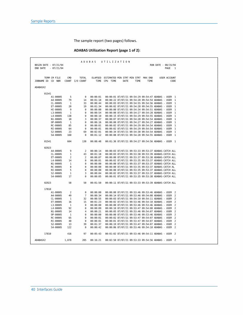
The sample report (two pages) follows.
ADABAS Utilization Report (page 1 of 2):
A D A B A S U T I L I Z A T I O N
BEGIN DATE - 07/21/94 RUN DATE - 08/15/94
END DATE - 07/21/94 PAGE 1
TERM CM FILE CMD TOTAL ELAPSED ESTIMATED MIN STRT MIN STRT MAX END USER ACCOUNT
JOBNAME ID CD NBR COUNT I/O COUNT TIME CPU TIME DATE TIME TIME CODE
ADABASX2
01541
A1-00005 5 0 00:00:01 00:00:01 87/07/21 09:54:29 09:54:47 ADABAS - USER 1
A4-00005 79 14 00:01:18 00:00:22 87/07/21 09:54:28 09:54:54 ADABAS - USER 1
CL-00005 1 33 00:00:44 00:00:03 87/07/21 09:54:55 09:54:56 ADABAS - USER 1
ET-00005 20 19 00:01:34 00:00:02 87/07/21 09:54:28 09:54:55 ADABAS - USER 1
HI-00005 9 0 00:00:00 00:00:00 87/07/21 09:54:34 09:54:51 ADABAS - USER 1
L3-00005 1 0 00:00:54 00:00:00 87/07/21 09:54:27 09:54:28 ADABAS - USER 1
L4-00005 138 0 00:00:10 00:00:15 87/07/21 09:54:29 09:54:55 ADABAS - USER 1
N1-00005 18 3 00:00:37 00:00:07 87/07/21 09:54:28 09:54:54 ADABAS - USER 1
OP-00005 1 0 00:00:16 00:00:00 87/07/21 09:54:27 09:54:27 ADABAS - USER 1
RC-00005 85 0 00:00:01 00:00:02 87/07/21 09:54:29 09:54:54 ADABAS - USER 1
RI-00005 64 0 00:00:01 00:00:02 87/07/21 09:54:29 09:54:54 ADABAS - USER 1
S2-00005 23 69 00:02:01 00:00:34 87/07/21 09:54:30 09:54:54 ADABAS - USER 1
S4-00005 160 0 00:01:12 00:00:08 87/07/21 09:54:28 09:54:55 ADABAS - USER 1
01541 604 138 00:08:48 00:01:36 87/07/21 09:54:27 09:54:56 ADABAS - USER 1
02923
A4-00005 9 2 00:00:14 00:00:03 87/07/21 09:53:33 09:53:37 ADABAS-CATCH ALL
CL-00005 1 43 00:01:18 00:00:03 87/07/21 09:53:38 09:53:39 ADABAS-CATCH ALL
ET-00005 2 2 00:00:07 00:00:00 87/07/21 09:53:37 09:53:38 ADABAS-CATCH ALL
L4-00005 14 0 00:00:01 00:00:02 87/07/21 09:53:35 09:53:37 ADABAS-CATCH ALL
N1-00005 1 0 00:00:00 00:00:00 87/07/21 09:53:37 09:53:37 ADABAS-CATCH ALL
RC-00005 8 0 00:00:00 00:00:00 87/07/21 09:53:35 09:53:37 ADABAS-CATCH AL
RI-00005 5 0 00:00:00 00:00:00 87/07/21 09:53:35 09:53:37 ADABAS-CATCH ALL
S2-00005 1 3 00:00:04 00:00:02 87/07/21 09:53:37 09:53:37 ADABAS-CATCH ALL
S4-00005 17 0 00:00:05 00:00:01 87/07/21 09:53:35 09:53:38 ADABAS-CATCH ALL
02923 58 50 00:01:50 00:00:11 87/07/21 09:53:33 09:53:39 ADABAS-CATCH ALL
17810
A1-00005 2 0 00:00:00 00:00:00 87/07/21 09:53:46 09:53:46 ADABAS - USER 2
A4-00005 49 7 00:00:34 00:00:14 87/07/21 09:53:46 09:54:08 ADABAS - USER 2
CL-00005 1 32 00:00:55 00:00:03 87/07/21 09:54:10 09:54:11 ADABAS - USER 2
ET-00005 16 15 00:01:23 00:00:02 87/07/21 09:53:46 09:54:10 ADABAS - USER 2
L3-00005 1 0 00:00:00 00:00:00 87/07/21 09:53:46 09:53:46 ADABAS - USER 2
L4-00005 92 0 00:00:09 00:00:10 87/07/21 09:53:47 09:54:08 ADABAS - USER 2
N1-00005 14 4 00:00:21 00:00:05 87/07/21 09:53:46 09:54:07 ADABAS - USER 2
OP-00005 1 0 00:00:00 00:00:00 87/07/21 09:53:46 09:53:46 ADABAS - USER 2
RC-00005 65 0 00:00:01 00:00:02 87/07/21 09:53:47 09:54:07 ADABAS - USER 2
RI-00005 40 0 00:00:01 00:00:01 87/07/21 09:53:47 09:54:07 ADABAS - USER 2
S2-00005 13 39 00:01:37 00:00:19 87/07/21 09:53:47 09:54:07 ADABAS - USER 2
S4-00005 122 0 00:00:42 00:00:06 87/07/21 09:53:46 09:54:10 ADABAS - USER 2
17810 416 97 00:05:43 00:01:02 87/07/21 09:53:46 09:54:11 ADABAS - USER 2
ADABASX2 1,078 285 00:16:21 00:02:50 87/07/21 09:53:33 09:54:56 ADABAS - USER 2

Sample Reports
Chapter 1: The ADABAS Interface 41
ADABAS Utilization Report (page 2 of 2):
A D A B A S U T I L I Z A T I O N
BEGIN DATE - 07/21/94 RUN DATE - 08/15/94
END DATE - 07/21/94 PAGE 2
TERM CM FILE CMD TOTAL ELAPSED ESTIMATED MIN STRT MIN STRT MAX END USER ACCOUNT
JOBNAME ID CD NBR COUNT I/O COUNT TIME CPU TIME DATE TIME TIME CODE
CICS15X
03085
-00000 1 0 00:00:12 00:00:00 87/07/21 14:02:01 14:02:01 ALL CICS USERS
BT-00004 1 0 00:00:00 00:00:00 87/07/21 14:02:06 14:02:06 ALL CICS USERS
ET-00000 2 1 00:00:04 00:00:00 87/07/21 14:02:15 14:02:26 ALL CICS USERS
L2-00001 1,004 48 00:04:37 00:00:45 87/07/21 14:05:55 14:06:07 ALL CICS USERS
L2-00002 380 15 00:02:06 00:00:17 87/07/21 14:06:23 14:06:27 ALL CICS USERS
L3-00004 52 30 00:07:37 00:00:03 87/07/21 14:02:03 14:06:23 ALL CICS USERS
L9-00004 3 1 00:00:18 00:00:00 87/07/21 14:02:16 14:02:26 ALL CICS USERS
N1-00004 1 0 00:00:08 00:00:00 87/07/21 14:02:15 14:02:15 ALL CICS USERS
OP-00004 1 9 00:01:06 00:00:01 87/07/21 14:02:15 14:02:16 ALL CICS USERS
RC-00000 4 0 00:00:00 00:00:00 87/07/21 14:02:15 14:06:07 ALL CICS USERS
RC-00004 17 0 00:00:01 00:00:00 87/07/21 14:02:05 14:06:23 ALL CICS USERS
S1-00004 6 9 00:01:39 00:00:02 87/07/21 14:02:14 14:06:23 ALL CICS USERS
03085 1,472 113 00:17:48 00:01:09 87/07/21 14:02:01 14:06:27 ALL CICS USERS
CICS15X 1,472 113 00:17:48 00:01:09 87/07/21 14:02:01 14:06:27 ALL CICS USERS
KWL1PR05
BT-00004 3 0 00:00:00 00:00:00 87/07/21 14:03:58 14:06:04 ALL OTHER USERS
CL-00004 3 0 00:00:00 00:00:00 87/07/21 14:03:59 14:06:05 ALL OTHER USERS
L3-00004 9 2 00:04:20 00:00:00 87/07/21 14:03:56 14:06:04 ALL OTHER USERS
OP-00004 3 2 00:03:28 00:00:00 87/07/21 14:03:55 14:06:03 ALL OTHER USERS
RC-00000 3 0 00:00:00 00:00:00 87/07/21 14:03:59 14:06:05 ALL OTHER USERS
RC-00004 6 0 00:00:00 00:00:00 87/07/21 14:03:57 14:06:04 ALL OTHER USERS
S1-00004 3 5 00:00:40 00:00:01 87/07/21 14:03:58 14:06:05 ALL OTHER USERS
30 9 00:08:29 00:00:02 87/07/21 14:03:55 14:06:05 ALL OTHER USERS
KWL1PR05 30 9 00:08:29 00:00:02 87/07/21 14:03:55 14:06:05 ALL OTHER USERS
2,580 407 00:42:37 00:04:00 87/07/21 09:53:33 14:06:27 ALL OTHER USERS
CAJS003I NORMAL END OF PROCESSING
ADABAS Job Charge Detail Report
The sample ADABAS Job Charge Detail Report, shown on the next page was obtained by executing a modified version of member ADADETR in the source library. The following system control statements were used.
System Control Statements
1...5...10...15...20...25...30...35...40...45...50...55...60...65 .80
CONFIG OTHE01F
SELECT 1 0
These Report Writer control statements were used to produce the report.

Sample Reports
42 Interfaces Guide
Report Control Statements
1...5...10...15...20...25...30...35...40...45...50...55...60...65 .80
CONFIG OTHE01F
SELECT 1 0
0HEADER A D A B A S J O B C H A R G E D E T A I L
0SORT 01608A2109908A2110708A1
0DISPLAY QA002156166144133134139140145146142
0RATE 1000500 100 001001 001
0DESCRIPT3****1381
0DESCRIPT2****0881
0DESCRIPT1****0181
0TITLE 02 TERM CM FILE JOBNAME ID CD NBR
1...5...10...15...20...25...30...35...40...45...50...55...60...65 .80
The sample report consists of two pages.

Sample Reports
Chapter 1: The ADABAS Interface 43
ADABAS Job Charge Detail Report (1 of 2):
A D A B A S J O B C H A R G E D E T A I L
BEGIN DATE - 07/21/94 RUN DATE - 08/15/94
END DATE - 07/21/94 PAGE 1
TERM CM FILE CMD ESTIMATED PROCESS ASSOCIATOR WORK DATA TOTAL I/O TOTAL PERCENT
JOBNAME ID CD NBR COUNT CPU TIME CHARGE I/O COUNT I/O COUNT I/O COUNT I/O COUNT CHARGE CHARGE TOTAL
ADABASX2
01541
A1-00005 5 00:00:01 $.29 0 0 0 0 $.00 $.29 .235
A4-00005 79 00:00:22 $6.16 6 8 0 14 $1.95 $8.11 6.572
CL-00005 1 00:00:03 $.72 30 2 1 33 $4.59 $5.31 4.303
ET-00005 20 00:00:02 $.59 0 19 0 19 $2.64 $3.23 2.617
HI-00005 9 00:00:00 $.06 0 0 0 0 $.00 $.06 .049
L3-00005 1 00:00:00 $.02 0 0 0 0 $.00 $.02 .016
L4-00005 138 00:00:15 $4.22 0 0 0 0 $.00 $4.22 3.420
N1-00005 18 00:00:07 $1.87 3 0 0 3 $.42 $2.29 1.856
OP-00005 1 00:00:00 $.01 0 0 0 0 $.00 $.01 .008
RC-00005 85 00:00:02 $.57 0 0 0 0 $.00 $.57 .462
RI-00005 64 00:00:02 $.43 0 0 0 0 $.00 $.43 .348
S2-00005 23 00:00:34 $9.55 0 69 0 69 $9.59 $19.14 15.509
S4-00005 160 00:00:08 $2.31 0 0 0 0 $.00 $2.31 1.872
01541 604 00:01:36 $26.80 39 98 1 138 $19.19 $45.99 37.267
02923
A4-00005 9 00:00:03 $.77 0 2 0 2 $.28 $1.05 .851
CL-00005 1 00:00:03 $.94 40 2 1 43 $5.97 $6.91 5.599
ET-00005 2 00:00:00 $.06 0 2 0 2 $.28 $.34 .276
L4-00005 14 00:00:02 $.43 0 0 0 0 $.00 $.43 .348
N1-00005 1 00:00:00 $.10 0 0 0 0 $.00 $.10 .081
RC-00005 8 00:00:00 $.05 0 0 0 0 $.00 $.05 .041
RI-00005 5 00:00:00 $.03 0 0 0 0 $.00 $.03 .024
S2-00005 1 00:00:02 $.42 0 3 0 3 $.42 $.84 .681
S4-00005 17 00:00:01 $.25 0 0 0 0 $.00 $.25 .203
02923 58 00:00:11 $3.05 40 9 1 50 $6.95 $10.00 8.104
17810
A1-00005 2 00:00:00 $.12 0 0 0 0 $.00 $.12 .097
A4-00005 49 00:00:14 $3.88 2 5 0 7 $.97 $4.85 3.930
CL-00005 1 00:00:03 $.70 28 2 2 32 $4.45 $5.15 4.173
ET-00005 16 00:00:02 $.47 0 15 0 15 $2.09 $2.56 2.074
L3-00005 1 00:00:00 $.02 0 0 0 0 $.00 $.02 .016
L4-00005 92 00:00:10 $2.81 0 0 0 0 $.00 $2.81 2.277
N1-00005 14 00:00:05 $1.49 2 1 1 4 $.56 $2.05 1.661
OP-00005 1 00:00:00 $.01 0 0 0 0 $.00 $.01 .008
RC-00005 65 00:00:02 $.43 0 0 0 0 $.00 $.43 .348
RI-00005 40 00:00:01 $.27 0 0 0 0 $.00 $.27 .219
S2-00005 13 00:00:19 $5.40 0 39 0 39 $5.42 $10.82 8.768
S4-00005 122 00:00:06 $1.76 0 0 0 0 $.00 $1.76 1.426
17810 416 00:01:02 $17.36 32 62 3 97 $13.49 $30.85 24.997
ADABASX2 1,078 00:02:50 $47.21 111 169 5 285 $39.63 $86.84 70.368

Sample Reports
44 Interfaces Guide
ADABAS Job Charge Detail Report (2 of 2):
A D A B A S J O B C H A R G E D E T A I L
BEGIN DATE - 07/21/94 RUN DATE - 08/15/94
END DATE - 07/21/94 PAGE 2
TERM CM FILE CMD ESTIMATED PROCESS ASSOCIATOR WORK DATA TOTAL I/O TOTAL PERCENT
JOBNAME ID CD NBR COUNT CPU TIME CHARGE I/O COUNT I/O COUNT I/O COUNT I/O COUNT CHARGE CHARGE TOTAL
CICS15X
03085
-00000 1 00:00:00 $.00 0 0 0 0 $.00 $.00 .000
BT-00004 1 00:00:00 $.01 0 0 0 0 $.00 $.01 .008
ET-00000 2 00:00:00 $.04 0 1 0 1 $.14 $.18 .146
L2-00001 1,004 00:00:45 $12.61 2 0 46 48 $6.72 $19.33 15.664
L2-00002 380 00:00:17 $4.71 2 0 13 15 $2.10 $6.81 5.519
L3-00004 52 00:00:03 $.76 6 0 24 30 $4.17 $4.93 3.995
L9-00004 3 00:00:00 $.06 1 0 0 1 $.14 $.20 .162
N1-00004 1 00:00:00 $.04 0 0 0 0 $.00 $.04 .032
OP-00004 1 00:00:01 $.21 7 1 1 9 $1.25 $1.46 1.183
RC-00000 4 00:00:00 $.03 0 0 0 0 $.00 $.03 .024
RC-00004 17 00:00:00 $.11 0 0 0 0 $.00 $.11 .089
S1-00004 6 00:00:02 $.45 3 1 5 9 $1.25 $1.70 1.378
03085 1,472 00:01:09 $19.03 21 3 89 113 $15.77 $34.80 28.200
CICS15X 1,472 00:01:09 $19.03 21 3 89 113 $15.77 $34.80 28.200
KWL1PR05
BT-00004 3 00:00:00 $.03 0 0 0 0 $.00 $.03 .024
CL-00004 3 00:00:00 $.03 0 0 0 0 $.00 $.03 .024
L3-00004 9 00:00:00 $.07 1 0 1 2 $.28 $.35 .283
OP-00004 3 00:00:00 $.09 0 2 0 2 $.28 $.37 .300
RC-00000 3 00:00:00 $.03 0 0 0 0 $.00 $.03 .024
RC-00004 6 00:00:00 $.03 0 0 0 0 $.00 $.03 .024
S1-00004 3 00:00:01 $.23 4 0 1 5 $.70 $.93 .753
30 00:00:02 $.51 5 2 2 9 $1.26 $1.77 1.432
KWL1PR05 30 00:00:02 $.51 5 2 2 9 $1.26 $1.77 1.432
2,580 00:04:00 $66.75 137 174 96 407 $56.66 $123.41 100.000
CAJS003I NORMAL END OF PROCESSING

Sample Reports
Chapter 1: The ADABAS Interface 45
ADABAS Job Charge Summary Report
The sample ADABAS Job Charge Detail Report, shown below, was obtained by executing a modified version of member ADASUMR in the source library. The following system control statements were used.
System Control Statements
1...5...10...15...20...25...30...35...40...45...50...55...60...65 .80
CONFIG OTHE01F
SELECT 1 0
These Report Writer control statements were used to produce the report.
Report Control Statements
1...5...10...15...20...25...30...35...40...45...50...55...60...65 .80
CONFIG OTHE01F
SELECT 1 0
0HEADER A D A B A S J O B C H A R G E S U M M A R Y
0SORT 01608A1109908A1
0DISPLAY QA002056166144133134139140145146142
0RATE 1000500 100 001001 001
0DESCRIPT2****1281
0DESCRIPT1****0181
0TITLE 02 TERMINAL JOBNAME ID
1...5...10...15...20...25...30...35...40...45...50...55...60...65 .80
ADABAS Job Charge Summary Report:
A D A B A S J O B C H A R G E S U M M A R Y
BEGIN DATE - 07/21/94 RUN DATE - 08/15/94
END DATE - 07/21/94 PAGE 1
TERMINAL CMD ESTIMATED PROCESS ASSOCIATOR WORK DATA TOTAL I/O TOTAL PERCENT
JOBNAME ID COUNT CPU TIME CHARGE I/O COUNT I/O COUNT I/O COUNT I/O COUNT CHARGE CHARGE TOTAL
ADABASX2
01541 604 00:01:36 $26.80 39 98 1 138 $19.19 $45.99 37.267
02923 58 00:00:11 $3.05 40 9 1 50 $6.95 $10.00 8.104
17810 416 00:01:02 $17.36 32 62 3 97 $13.49 $30.85 24.997
ADABASX2 1,078 00:02:50 $47.21 111 169 5 285 $39.63 $86.84 70.368
CICS15X
03085 1,472 00:01:09 $19.03 21 3 89 113 $15.77 $34.80 28.200
CICS15X 1,472 00:01:09 $19.03 21 3 89 113 $15.77 $34.80 28.200
KWL1PR05
30 00:00:02 $.51 5 2 2 9 $1.26 $1.77 1.432
KWL1PR05 30 00:00:02 $.51 5 2 2 9 $1.26 $1.77 1.432
2,580 00:04:00 $66.75 137 174 96 407 $56.66 $123.41 100.000
CAJS003I NORMAL END OF PROCESSING

Sample Reports
46 Interfaces Guide
EXTDATA Reports
There are sample CA Earl and CA Easytrieve reports that will process the ADABAS Interface EXTDATA records.
Note: The EXTDATA record layout is described in the chapter "EXTDATA Reporting" in the User Guide.
OPTION LIST OFF
NOTE ******************************************************************
NOTE * REPORT ID: ERXTA001 *
NOTE * REPORT NAME: ADABAS COMMAND SUMMARY *
NOTE * DESCRIPTION: THIS SUMMARY REPORT WILL COLLATE AND SUMMARIZE*
NOTE * ADABAS ACTIVITY FROM AN ADABAS COMMAND LOG *
NOTE * SUMMARIZING KEYS ARE THE ADABAS JOB NAME, *
NOTE * THE CLIENT USER ID, THE FILE NUMBER AND *
NOTE * COMMAND ID. THE REPORT WILL SHOW THE NUMBER *
NOTE * OF COMMANDS OF EACH TYPE, THE NUMBER OF *
NOTE * DESCRIPTORS UPDATED, THE TOTAL NUMBER OF *
NOTE * I/OS AND THE APPROXIMATE CPU TIME. *
NOTE * *
NOTE * RECORD TYPES: MRXTHDR, *
NOTE * MRXTSIEA *
NOTE * *
NOTE * EXTDATA RECORD: SIEA *
NOTE * *
NOTE * MACROS: *
NOTE ******************************************************************
OPTION PRINTER = 132
OPTION PAGE = 60
OPTION PRECISION = ALL
OPTION CPAGE = 60
HISTIN: FILE JARS RECORD=3697
DEF INAREA 1-3697 X
COPY MRXTHDR
COPY MRXTSIEA
NOTE ******************************************************************
NOTE * SELECTING FROM HISTORY FILE EXTDATA, SPECIFICALLY SIEA *
NOTE ******************************************************************
!
IF PROCID NOT = ':' OR
EXTTYPE NOT = 'SIEA'
THEN GOTO START
ENDIF
!
NOTE ******************************************************************
NOTE * REPORT PROCESSING SECTION *
NOTE ******************************************************************
!

Sample Reports
Chapter 1: The ADABAS Interface 47
REPORT 'ADABAS ACTIVITY SUMMARY'
TITLE ' '
TITLE @1 'REPORT ID: ERXTA001' @54 'SYSTEM ID:' SID
TITLE @1 'SOURCE : ADABAS CLOG' @54 ' ADABAS:' EXTSIEA_JOB_NAME
TITLE @54 ' USER ID:' EXTSIEA_USER_ID
TITLE @54 ' ACCOUNT:' EXTSIEA_ACCOUNTING
TITLE ' '
!
CONTROL (EXTSIEA_JOB_NAME) (EXTSIEA_USER_ID) SKIP
(EXTSIEA_COMMAND) (EXTSIEA_FILE_NUMBER)
!
PRINT TOTALS ONLY
@1 ' '
EXTSIEA_COMMAND
EXTSIEA_FILE_NUMBER
(EXTSIEA_REC_COUNT)
(EXTSIEA_DESC_UPDATES)
(EXTSIEA_TOTAL_IOS)
(EXTSIEA_CPU_TIME)
END
LIST OFF
******************************************************************
* REPORT ID: EZXTA001 *
* REPORT NAME: ADABAS COMMAND SUMMARY *
* DESCRIPTION: THIS SUMMARY REPORT WILL COLLATE AND SUMMARIZE*
* ADABAS ACTIVITY FROM AN ADABAS COMMAND LOG *
* SUMMARIZING KEYS ARE THE ADABAS JOB NAME, *
* THE CLIENT USER ID, THE FILE NUMBER AND *
* COMMAND ID. THE REPORT WILL SHOW THE NUMBER *
* OF COMMANDS THAT MATCH THE CRITERIA, THE *
* NUMBER OF DESCRIPTORS UPDATED, THE TOTAL *
* NUMBER OF I/OS AND THE APPROXIMATE CPU TIME. *
* *
* RECORD TYPES: MZXTHDR, *
* MZXTSIEA *
* *
* EXTDATA RECORD: SIEA *
* *
******************************************************************
PARM ABEXIT (SNAP) DEBUG (FLDCHK STATE)
FILE EXTDATA
%MZXTHDR
%MZXTSIEA
*
JOB INPUT EXTDATA
IF PROCID = ':' AND EXTTYPE = 'SIEA'
GOTO PROCESS_DATA
ELSE
GOTO JOB

Sample Reports
48 Interfaces Guide
END-IF
PROCESS_DATA
*
PRINT REPORT1
*
REPORT REPORT1 SUMMARY SPACE 0 PAGESIZE (60 60) LINESIZE 132 NOADJUST +
SUMCTL DTLCOPY
*
SEQUENCE EXTSIEA_JOB_NAME EXTSIEA_USER_ID EXTSIEA_COMMAND +
EXTSIEA_FILE_NUMBER
*
CONTROL EXTSIEA_JOB_NAME EXTSIEA_USER_ID NEWPAGE +
EXTSIEA_COMMAND EXTSIEA_FILE_NUMBER
*
TITLE 01 COL 51 'ADABAS ACTIVITY SUMMARY'
TITLE 02 ' '
TITLE 03 COL 1 'REPORT ID: EZXTA001' COL 54 'SYSTEM ID ' SID
TITLE 04 COL 1 'SOURCE : ADABAS' COL 54 'ADABAS ' +
EXTSIEA_JOB_NAME
TITLE 05 COL 54 'USER ID ' +
EXTSIEA_USER_ID
TITLE 06 COL 54 'ACCOUNT ' +
EXTSIEA_ACCOUNTING
LINE EXTSIEA_COMMAND ' ' +
EXTSIEA_FILE_NUMBER ' ' +
EXTSIEA_REC_COUNT ' ' +
EXTSIEA_DESC_UPDATE ' ' +
EXTSIEA_TOTAL_IOS ' ' +
EXTSIEA_CPU_TIME
The sample output looks like this:

Reporting Considerations
Chapter 1: The ADABAS Interface 49
108/01/04 ADABAS ACTIVITY SUMMARY
REPORT ID: ERXTA001 SYSTEM ID: XAD1
SOURCE : ADABAS CLOG ADABAS: ABEJUA1
USER ID: TSU05326
ACCOUNT: FITCH
-------------------------------------------------------------------------------------------------------------------------------
COMMAND FILE COMMAND DESCRIPTORS TOTAL CPU TIME
CODE NUMBER COUNT UPDATED I/OS HOURS
-------------------------------------------------------------------------------------------------------------------------------
CL 0 2 0 0 0.00017
-------- -------------- -------------- --------------
CL 2 0 0 0.00017
-------- -------------- -------------- --------------
L3 11 7 0 22 0.00635
L3 14 4 0 13 0.00375
-------- -------------- -------------- --------------
L3 11 0 35 0.01010
-------- -------------- -------------- --------------
L9 11 2 0 3 0.00109
L9 14 1 0 2 0.00068
-------- -------------- -------------- --------------
L9 3 0 5 0.00177
-------- -------------- -------------- --------------
OP 0 2 0 3 0.00115
-------- -------------- -------------- --------------
OP 2 0 3 0.00115
-------- -------------- -------------- --------------
RC 0 15 0 0 0.00125
-------- -------------- -------------- --------------
RC 15 0 0 0.00125
-------- -------------- -------------- --------------
S1 11 21 0 35 0.02129
S1 14 20 0 22 0.01461
-------- -------------- -------------- --------------
S1 41 0 57 0.03590
-------- -------------- -------------- --------------
-------- -------------- -------------- --------------
74 0 100 0.05034
-------- -------------- -------------- --------------
-------- -------------- -------------- --------------
74 0 100 0.05034
-------- -------------- -------------- --------------
Reporting Considerations
This section identifies those areas in the operation of the Report Writer that are affected by the introduction of ADABAS data. Specifically, the Basic Accounting Table and the Output Data Elements Table are replaced when producing reports with ADABAS data.

Reporting Considerations
50 Interfaces Guide
ADABAS Data Elements
The following is a list of ADABAS data elements:
Job Name
User ID
Command Code
File Number
Associator I/Os
Data I/Os
Work I/Os
Posted ECBs
Descriptors Updated
Command Duration (Elapsed Time)
Estimated CPU Time
Command Count
Minimum Start Date
Minimum Start Time
Maximum End Time
Day of Week Code
User Account Code
ADABAS Basic Accounting Table
The following table replaces the Basic Accounting Table for designing ADABAS reports:
ADABAS Basic Accounting Table:
Field Name Field Position
Field Length
F* Notes DE
ID
CPU Identification 1 1 a 'S' 57
Reserved 2-3 2 -
Min Start Date 4-9 6 a YYMMDD 60
Min Start Time 10-15 6 a HHMMSS 61
Job Name 16-23 8 a 04
Reserved 24-25 2 -
Command Count 26-27 2 b 56
Processing ID 28 1 a 'C' 03
Record ID 29-36 8 a *ADABAS* 10
Min Start Time 37-42 6 a HHMMSS 12

Reporting Considerations
Chapter 1: The ADABAS Interface 51
Field Name Field Position
Field Length
F* Notes DE
ID
Min Start Date 43-48 6 a YYMMDD 06
Command Code 49-50 2 a 07
Max End Time 51-56 6 a HHMMSS 13
Concatenation of Terminal ID, Job Name, Command Code
57-76 20 a
Reserved 77-98 22 -
Terminal ID/User ID 99-106 8 a 11
Concatenation of Command Code and File Number
107-114 8 a
Reserved 115-170 56 -
Elapsed Time 171-176 6 p In minutes, to 5 decimal places 25,65,90
Estimated CPU Time 177-182 6 p 26,66,91
Reserved 183-212 30 -
Associator I/O count 213-219 7 p 33
Work I/O Count 220-226 7 p 34
Reserved 227-247 21 -
Data I/O Count 248-254 7 p 39
Total I/O Count 255-261 7 p 40
I/O Index 262-265 4 p 78
Reserved 266-295 30 -
Group Code #1 Group Code #2 Group Code #3
296 297 298
1 1 1
a a a
Blank unless filled by grouping feature 84 85 86
Reserved 299-364 66 -
Posted ECBS 365-368 4 p A5
Descriptors Updated 369-372 4 p A6
Reserved 373-417 45 -
CPU Index 418-419 2 p D0
Reserved 420-436 16 -

Contents of Target Libraries
52 Interfaces Guide
Field Name Field Position
Field Length
F* Notes DE
ID
Day of Week Code 437 1 a D5,D6
Group Code #4 Group Code #5 Group Code #6
438 439 440
1 1 1
a a a
Blank unless filled by grouping feature D7 D8 D9
Reserved 441-518 76 -
User Account Code 519-534 16 a Blank unless JOBNAME and USERID match entry in QAACT table
F4
Reserved 535-550 16 -
Processor Time 551-556 6 p 999999V99999C; hours 29,69
Processor Charge 557-562 6 p 999999999V99C; dollars 44
I/O Time 563-568 6 p 999999V99999C; hours 30,70
I/O Charge 569-574 6 p 999999999V99C; dollars 45
Reserved 575-584 10 -
Total Charge 585-590 6 p 999999999V99C; dollars 46
Reserved 591-608 18 -
F* Format Indicator a=alphanumeric b=binary p=packed decimal
Contents of Target Libraries
CAJRMAC Macros: QAACT QCPU QENVR
CAJRSAMP Sample User Tables:
JSIQAACT JSIQCPU JSIQENVR
CAJRSAMP Sample User Exit:
ADAEXIT
CAJRJCL Sample JCL: ADAINTR ADAUTLR ADADETR ADASUMR
CAJREARL CA EARL Source:
MRXTSIEA
CAJREZTR CA Easytrieve Source:
MZXTSIEA

Contents of Target Libraries
Chapter 1: The ADABAS Interface 53
CAI.CAJRLOAD Library Members
Load Modules: JSIRTTQA JSQAPMSG JSQA0000 JSQA1000
IVP User Tables: QAACT QCPU QENVR

Chapter 2: The Interface to CA Datacom/DB 55
Chapter 2: The Interface to CA Datacom/DB
The CA JARS interface to CA Datacom/DB is your tool for effectively analyzing database activity. It provides data that yields a thorough picture of system utilization.
The Interface lets you:
■ measure user productivity
■ evaluate software efficiency
■ provide equitable customer billing and cost distribution
The Interface compiles information about database resource usage into a format that can be used for producing reports with the Report Writer. To accomplish this, the Interface reformats your CA Datacom/DB Accounting Table records, producing a CA JARS summary file. All relevant data required for you to monitor and allocate resource utilization is retained on the summary file. The Basic Accounting Table presented later in this chapter provides a detailed list of the data elements available for reporting.
This section contains the following topics:
Benefits of the Interface to CA Datacom/DB (see page 56) Input and Output (see page 56) Cost Center Identification (see page 56) The Interface to CA Datacom/DB Components (see page 57) System Requirements (see page 57) Creating the Summary File (see page 58) Record Descriptions and Processing Rules (see page 70) Sample Reports (see page 73) Reporting Considerations (see page 83) Contents of Target Libraries (see page 86)

Benefits of the Interface to CA Datacom/DB
56 Interfaces Guide
Benefits of the Interface to CA Datacom/DB
The Interface permits chargeback and performance reporting by:
■ jobname
■ operator ID
The Interface uses the Report Writer as its reporting component. All report writer benefits, including combined batch and chargeback and reporting, are available as part of the Interface.
This interface can also be used to generate EXTDATA records. EXTDATA records can be used for reporting with CA EARL and CA Easytrieve. The layout and format of the EXTDATA records are described in the chapter "EXTDATA Reporting" in the User Guide.
In addition, the EXTDATA records can be used in conjunction with CA PMA Chargeback to create billing and chargeback systems for Datacom resource utilization.
Input and Output
The interface to CA Datacom/DB converts statistics from the CA Datacom/DB Accounting Table into a summary file. The Interface accomplishes this task by reformatting the CA Datacom/DB Accounting Facility record. The summary file contains level 7 history records with a processing ID of C. This processing ID is uniquely suited to software subsystems that execute transaction-oriented tasks, such as CA Datacom/DB.
The Interface to CA Datacom/DB will also generate EXTDATA records if the CAIJSACT DD Name is present and is able to be opened during processing.
Cost Center Identification
The Interface provides combined billing and reporting by placing a user-defined account code into the appropriate field of the summary record.
A User Account Table is provided to match a jobname and/or operator ID with an accounting table record and places a cost center identifier (account code) in the output record.
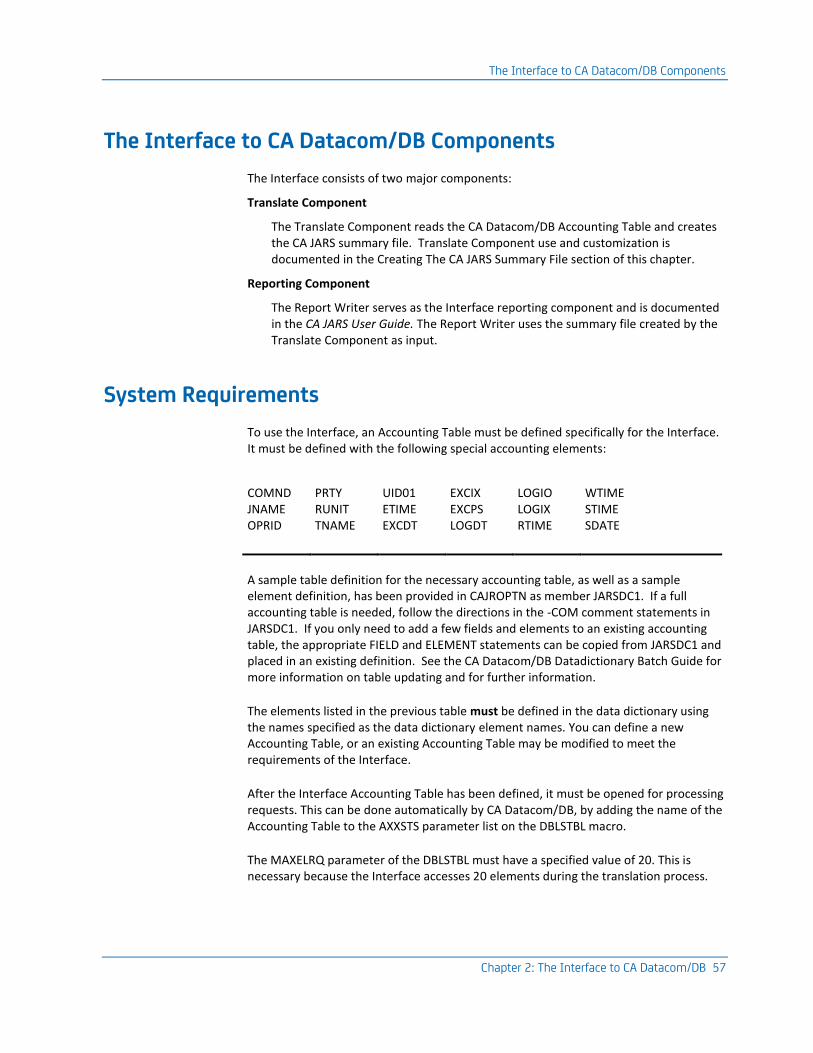
The Interface to CA Datacom/DB Components
Chapter 2: The Interface to CA Datacom/DB 57
The Interface to CA Datacom/DB Components
The Interface consists of two major components:
Translate Component
The Translate Component reads the CA Datacom/DB Accounting Table and creates the CA JARS summary file. Translate Component use and customization is documented in the Creating The CA JARS Summary File section of this chapter.
Reporting Component
The Report Writer serves as the Interface reporting component and is documented in the CA JARS User Guide. The Report Writer uses the summary file created by the Translate Component as input.
System Requirements
To use the Interface, an Accounting Table must be defined specifically for the Interface. It must be defined with the following special accounting elements:
COMND JNAME OPRID
PRTY RUNIT TNAME
UID01 ETIME EXCDT
EXCIX EXCPS LOGDT
LOGIO LOGIX RTIME
WTIME STIME SDATE
A sample table definition for the necessary accounting table, as well as a sample element definition, has been provided in CAJROPTN as member JARSDC1. If a full accounting table is needed, follow the directions in the -COM comment statements in JARSDC1. If you only need to add a few fields and elements to an existing accounting table, the appropriate FIELD and ELEMENT statements can be copied from JARSDC1 and placed in an existing definition. See the CA Datacom/DB Datadictionary Batch Guide for more information on table updating and for further information.
The elements listed in the previous table must be defined in the data dictionary using the names specified as the data dictionary element names. You can define a new Accounting Table, or an existing Accounting Table may be modified to meet the requirements of the Interface.
After the Interface Accounting Table has been defined, it must be opened for processing requests. This can be done automatically by CA Datacom/DB, by adding the name of the Accounting Table to the AXXSTS parameter list on the DBLSTBL macro.
The MAXELRQ parameter of the DBLSTBL must have a specified value of 20. This is necessary because the Interface accesses 20 elements during the translation process.

Creating the Summary File
58 Interfaces Guide
The Interface reads the Accounting Table via CA Datacom/DB services. Therefore, the Interface must have a User Requirements Table (URT) associated with it. Because the Interface makes use of the dynamic user requirements load method, two URTs are provided with the Interface. Both URTs may be found in CAJRSAMP. DCURT1 contains the required DBURINF and DBUREND macros. Review DCURT1 to modify the URT to meet installation standards. Do not modify the OPEN, URTABLE, and USRNTRY parameter values. DCURT2 contains the required DBURSTR, DBURTBL, and DBUREND macros. Review DCURT2 to modify the URT to meet installation standards. Do not modify the ACCESS parameter value.
Note: DCURT1 and DCURT2 should be assembled as non-reentrant. If non-reentrant is not specified on the assembly, execution of JSI results in a product return code 16, error code 4.
Creating the Summary File
The Translate Component
This section contains reference information and examples that show you how to run the Translate Component. The Translate Component transforms the Accounting Table into a CA JARS summary file.
The term CA JARS summary file should not be confused with a summary file as created by the CA JARS SORT statement. The summary file is actually a detail-level file. Consequently, the term can be misleading. It is referred to as a summary file because the output of the Translate Component summarizes CA Datacom/DB statistics into one CA JARS record. On the other hand, the CA JARS reporting component's summarization feature is a powerful and effective method of producing summary information based on user-defined summary criteria. For details, see the section on the CA JARS SORT statement in the CA JARS User Guide.
This chapter covers the following Translate Component topics:
■ control statement use and syntax
■ JCL
■ specification of a User Account Code Table
The Translate Component uses the Accounting Table as input. The first part of this chapter documents the CA Datacom/DB System tasks for defining and activating the Accounting Table needed. This chapter assumes that the CA Datacom/DB System tasks for creating and activating the Accounting Table were completed as specified earlier in this chapter.

Creating the Summary File
Chapter 2: The Interface to CA Datacom/DB 59
Preparing Translate Control Statements
The Translate Component uses the following control statements.
Control Statement Purpose
Datacom Supplies system parameters.
CRITERIA Permits file segmentation by date.
Datacom
This parameter statement supplies the CA Datacom Interface with installation-dependent defaults.
Command Keywords/Operands Default
Datacom [SNAP nnnn] 0010
[CPUID x ] space
[ACCT name] none
[DATABASE nnn] none
[TBLNAM xxx] none
SNAP nnnn
specifies the count of rejected or invalid records to be snap dumped. If omitted, the Interface displays the first 10 records that it is unable to process successfully. To suppress this option, specify SNAP 0.
CPUID x
specifies the one-character CPU identifier that is put in all summary records. This CPU identification can be used by the report program for various grouping and chargeback rate application functions. If omitted, the Interface places a blank in the CPU identifier in the summary records.
ACCT name
specifies the member name of the User Account Table. See the section Creating A User Accounting Table later in this chapter.
DATABASE nnn
specifies the three-character database identifier that contains the Accounting Table to be translated.
TBLNAM xxx
specifies the three-character table name of the Accounting Table to be translated.
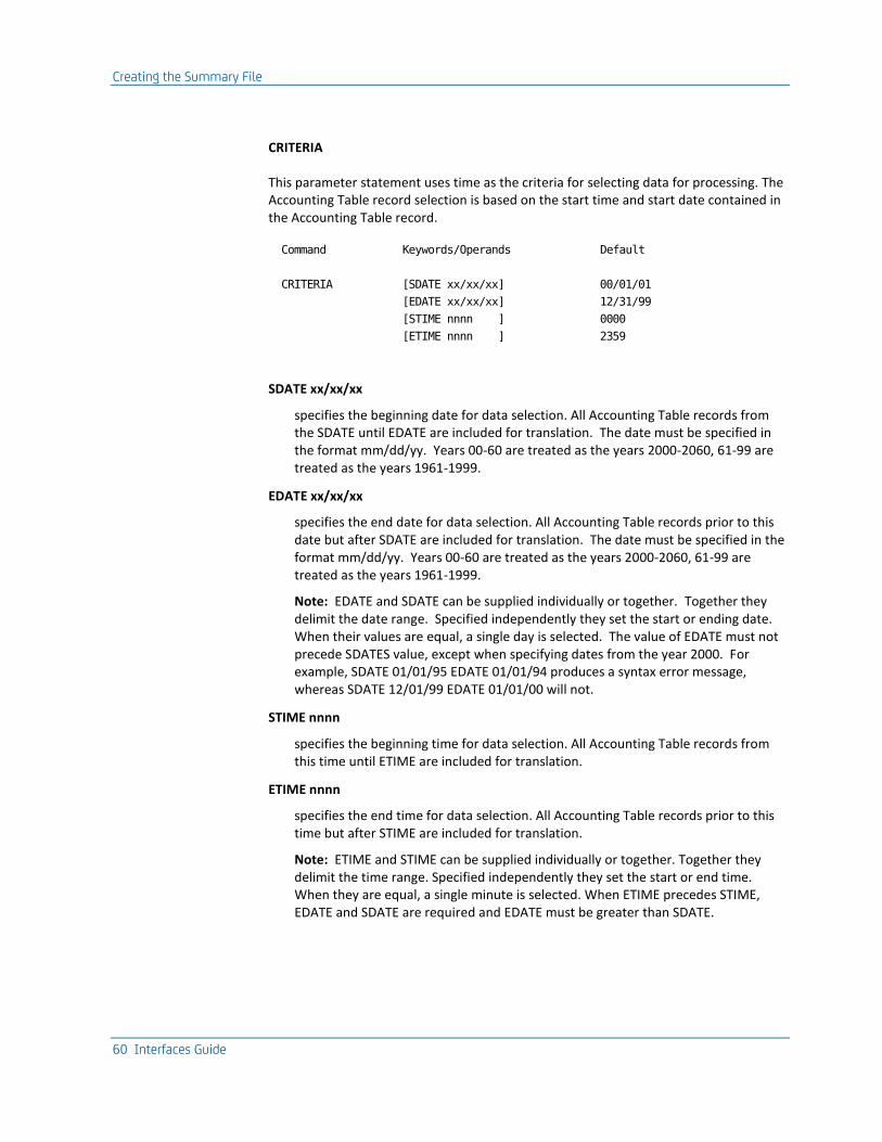
Creating the Summary File
60 Interfaces Guide
CRITERIA
This parameter statement uses time as the criteria for selecting data for processing. The Accounting Table record selection is based on the start time and start date contained in the Accounting Table record.
Command Keywords/Operands Default
CRITERIA [SDATE xx/xx/xx] 00/01/01
[EDATE xx/xx/xx] 12/31/99
[STIME nnnn ] 0000
[ETIME nnnn ] 2359
SDATE xx/xx/xx
specifies the beginning date for data selection. All Accounting Table records from the SDATE until EDATE are included for translation. The date must be specified in the format mm/dd/yy. Years 00-60 are treated as the years 2000-2060, 61-99 are treated as the years 1961-1999.
EDATE xx/xx/xx
specifies the end date for data selection. All Accounting Table records prior to this date but after SDATE are included for translation. The date must be specified in the format mm/dd/yy. Years 00-60 are treated as the years 2000-2060, 61-99 are treated as the years 1961-1999.
Note: EDATE and SDATE can be supplied individually or together. Together they delimit the date range. Specified independently they set the start or ending date. When their values are equal, a single day is selected. The value of EDATE must not precede SDATES value, except when specifying dates from the year 2000. For example, SDATE 01/01/95 EDATE 01/01/94 produces a syntax error message, whereas SDATE 12/01/99 EDATE 01/01/00 will not.
STIME nnnn
specifies the beginning time for data selection. All Accounting Table records from this time until ETIME are included for translation.
ETIME nnnn
specifies the end time for data selection. All Accounting Table records prior to this time but after STIME are included for translation.
Note: ETIME and STIME can be supplied individually or together. Together they delimit the time range. Specified independently they set the start or end time. When they are equal, a single minute is selected. When ETIME precedes STIME, EDATE and SDATE are required and EDATE must be greater than SDATE.

Creating the Summary File
Chapter 2: The Interface to CA Datacom/DB 61
Creating a User Accounting Table
The Interface Translate Component creates CA JARS summary records from the Accounting Table. One item in this translation is the assignment of a cost center identification to each record.
For transaction activity, the Translate Component examines the two identifiers
■ job name
■ operator ID
and searches the table sequentially from beginning to end. The table is not sorted before the search. The user accounting information contained in the first entry that matches the Accounting Table record fields is inserted into the summary record. Any identifier that is omitted is considered a match. An asterisk can be used as a wild-card character.
Example
Suppose a table record has the following values for the identifiers:
Job Name Operator
BAGJA01 JLB
All of the following identifiers for User Accounting Table entries produce a match.
Job Name Operator
BAGJA01T JLB
blank J*
*******T blank
blank JLB
B******* blank
Because the table is searched sequentially from top to bottom, the order of inclusion is significant. Although all the previous examples met the criteria, if all of them had been included in a single table, only the first one would be used to assign the cost center identification. The use of the asterisk as a wild-card character is illustrated by this example.
The User Accounting Table is built by assembling a set of macro instructions. You must follow the rules for coding Assembler Language macro statements when coding the table. During assembly, object code is generated as the statements are processed. If serious errors in the macro specification are detected, a message is issued and assembly continues even though the assembled module may not produce the intended results.

Creating the Summary File
62 Interfaces Guide
Initiating a User Accounting Table
The TYPE=INITIAL macro must be coded first, followed by one TYPE=ENTRY for each desired search key. The macros are terminated by a TYPE=FINAL.
Macro Operand
CAIDC01 TYPE=INITIAL
TYPE=INITIAL
specifies the beginning of the User Accounting Table. This statement is required. Code only one TYPE=INITIAL.
Defining a User Accounting Table Cost Center
Use the TYPE=ENTRY statements to define your cost centers and have the Translate Component associate these with the desired Transaction, Terminal, User ID combinations.
There may be any number of TYPE=ENTRY statements.
Macro Operands
CAIDC01 TYPE=ENTRY
[,JOBNAME='cccccccc']
[,OPRID='ccc']
[,ACCT='cccccccccccccccc']
[,DISP=DELETE|KEEP]
TYPE=ENTRY
specifies that this statement defines an entry in the table.
JOBNAME='cccccccc'
specifies the 1- to 8-character job name identifier of jobs whose execution is to be attributed to the cost center defined in this table entry.
OPRID='ccc'
specifies the 1- to 3-character operator identification of table records whose utilization statistics are to be attributed to the cost center defined in this table entry.
ACCT='cccccccccccccccc'
specifies the 1- to 16-character cost center identification that is placed in the user accounting information field of the summary record.

Creating the Summary File
Chapter 2: The Interface to CA Datacom/DB 63
DISP=DELETE|KEEP
specifies the final record disposition when a match is found. When DISP=DELETE is coded, records are omitted from further processing.
Note: JOBNAME and OPRID are both optional. When not specified, the default is blanks, which is an automatic match.
Terminating a User Accounting Table
The assembly of the User Accounting Table is terminated when the assembler encounters the TYPE=FINAL. You must code one, and only one, TYPE=FINAL. This statement must be the last assembler statement in the assembler input. The TYPE=FINAL causes assembler statements necessary for proper table length calculations to be generated. It also generates the assembler END statement.
Macro Operand
CAIDC01 TYPE=FINAL
TYPE=FINAL
specifies the end of the User Accounting Table. This statement is required. You must code only one TYPE=FINAL immediately before the assembler END statement.
Invoking the User Accounting Table
To invoke the User Accounting Table lookup process in the Interface, the linkedited member name must be specified on the ACCT option of the Datacom statement.
More information:
Preparing Translate Control Statements (see page 59)

Creating the Summary File
64 Interfaces Guide
User Accounting Table Examples
Example 1. The user's configuration:
■ Job BAGJA011 is assigned to 'OVERHEAD'. It is the computer operators' CA Datacom/DB backup job.
■ Jobs BAGJA012 and BAGJA013 are assigned to 'ACCOUNTING'.
■ Job BAGJA014 is assigned to 'PAYROLL'.
CAIDC01 TYPE=INITIAL
CAIDC01 TYPE=ENTRY,JOBNAME='BAGJA011',ACCT='OVERHEAD'
CAIDC01 TYPE=ENTRY,JOBNAME='BAGJA012',ACCT='ACCOUNTING'
CAIDC01 TYPE=ENTRY,JOBNAME='BAGJA013',ACCT='ACCOUNTING'
CAIDC01 TYPE=ENTRY,JOBNAME='BAGJA014',ACCT='PAYROLL'
CAIDC01 TYPE=FINAL
Example 2. The user's configuration:
■ All jobs starting with a 'D' with operator IDs beginning with an 'L' should be assigned to 'DEVELOPMENT'.
■ All operator IDs of 'OPM' should be assigned to 'OPERATIONS'.
■ All operator IDs beginning with a 'P0' should be assigned to 'PAYROLL'.
■ All jobs beginning with a 'C' should be assigned to 'OVERHEAD'.
CAIDC01 TYPE=INITIAL
CAIDC01 TYPE=ENTRY,JOBNAME='D*******',OPRID='L**',ACCT='DEVELOPMENT'
CAIDC01 TYPE=ENTRY,OPRID='OPM',ACCT='OPERATIONS'
CAIDC01 TYPE=ENTRY,JOBNAME='C*******',ACCT='OVERHEAD'
CAIDC01 TYPE=ENTRY,OPRID='P0*',ACCT='PAYROLL'
CAIDC01 TYPE=FINAL
Operations
Execution of the CA JARS Interface to CA Datacom/DB requires a minimum region size of 200K. In addition, several interrelated files are also required. The following list describes these required data sets and their functions:
DDName Description
STEPLIB This statement describes the load library that was loaded from the distribution tape.
CAIJFPR This statement describes the SYSOUT data set for generated display messages.
CAIJFSN This statement describes a SYSOUT data set for generated snap dumps.

Creating the Summary File
Chapter 2: The Interface to CA Datacom/DB 65
DDName Description
CAIJSACT This statement describes the output EXTDATA data set. This file must have these attributes:
RECFM=VB LRECL=8188 BLKSIZE=8192 or more
SYSUDUMP This statement describes a SYSOUT data set for dump output in the case of an abnormal termination.
CAIDCS6 This statement describes the output file written by the interface. It is this file that is input to the Report Writer. This file must have the following attributes:
RECFM=VB LRECL=612 BLKSIZE=6233
CAIJFIN This statement describes the data set that contains the interface control statements.

Creating the Summary File
66 Interfaces Guide
The following sample JCL can be used to execute the Interface to CA Datacom/DB. It is included as member DCINTR in CAJRJCL. Sample output from a run using a slightly modified version of this JCL can be found in the Reporting Considerations section of this chapter.
Sample JCL For CA Datacom/DB Interface Execution:
//DCINTR JOB ...,CLASS=A,MSGCLASS=A
//*
//*
//* THIS JOB EXECUTES THE CA JARS CA Datacom/DB INTERFACE TO
//* PRODUCE A JARS LEVEL 7 HISTORY FILE.
//*
//* THE FOLLOWING STATEMENTS ARE INSTALLATION-DEPENDENT
//* AND MUST BE MODIFIED ACCORDINGLY:
//* . JOB ACCOUNTING & CLASS INFORMATION
//* . STEPLIB DSN= CA JARS LOAD LIBRARY
//* . CAIDCS6 DSN= CA JARS LEVEL 7 HISTORY FILE (OUTPUT)
//* . CAIJFIN INTERFACE CONTROL STATEMENTS
//*
//* VOLUME AND UNIT DESIGNATORS WHICH POINT TO THE ACTUAL
//* VOLUMES ON WHICH YOUR DATA SETS RESIDE AND SPACE
//* PARAMETERS WHICH CORRESPOND TO THE SIZE OF YOUR DATA
//* MUST ALSO BE MODIFIED.
//*
//* REFER TO MEMBER DCINTR IN THE CAJRJCL
//*
//DCSTEP EXEC PGM=JSI,PARM='XXX00480,JSDC0000'
//STEPLIB DD DSN=CAI.CAJRLOAD,DISP=SHR
//CAIJFPR DD SYSOUT=*
//CAIJFSN DD SYSOUT=*
//SYSUDUMP DD SYSOUT=*
//CAIDCS6 DD DSN=CAI.JARS.HISTORY.DATA,DISP=(,CATLG),
// DCB=(RECFM=VB,LRECL=612,BLKSIZE=6233),
// UNIT=uuuu,VOL=SER=vvvvvv,
// SPACE=(TRK,(pp,ss),RLSE)
//CAIJSACT DD DSN=CAI.DATACOM.EXTDATA, -- Change to your needs
// DISP=(NEW,CATLG,DELETE),
// UNIT=uuuu,
// SPACE=(CYL,(pp,ss),RLSE),
// DCB=(RECFM=VB,LRECL=8188,BLKSIZE=bbbb),
// VOL=SER=vvvvvv
//CAIJFIN DD *
Datacom DATABASE 005 TBLNAM A04 SNAP 25 CPUID D ACCT JSDCACCT
/*
//

Creating the Summary File
Chapter 2: The Interface to CA Datacom/DB 67
The following sample JCL can be used to create an CA Datacom/DB Utilization Report using the Report Writer. It is included as member DCUTLR in CAJRJCL.
Sample JCL For CA Datacom/DB Utilization Report:
//DCUTLR JOB ...,TSOARS,CLASS=A,MSGCLASS=A
//*
//*
//* THIS JOB EXECUTES THE CA JARS REPORT PROGRAM TO PRODUCE
//* A CA Datacom/DB UTILIZATION REPORT.
//*
//* THE FOLLOWING STATEMENTS ARE INSTALLATION-DEPENDENT
//* AND MUST BE MODIFIED ACCORDINGLY:
//* . JOB ACCOUNTING & CLASS INFORMATION
//* . STEPLIB DSN= CA JARS LOAD LIBRARY
//* . CAIJSHST DSN= CA JARS LEVEL 7 HISTORY FILE
//*
//* SPACE PARAMETERS, APPROPRIATE TO THE SIZE OF YOUR
//* DATA, SHOULD BE USED IN THE 'SORTWK' AND 'CAIJS'
//* STATEMENTS.
//*
//* REFER TO MEMBER DCINTR IN THE CAJRJCL
//*
//JARSSTEP EXEC PGM=JSIMAIN
//STEPLIB DD DSN=CAI.CAJRLOAD,DISP=SHR
//SORTMSG DD SYSOUT=*
//CAIJSPRT DD SYSOUT=*
//CAIJSNAP DD SYSOUT=*
//SYSOUT DD SYSOUT=*
//SYSUDUMP DD SYSOUT=*
//SORTWK01 DD SPACE=(CYL,(1,1)),UNIT=SYSDA
//SORTWK02 DD SPACE=(CYL,(1,1)),UNIT=SYSDA
//SORTWK03 DD SPACE=(CYL,(1,1)),UNIT=SYSDA
//CAIJSCT1 DD SPACE=(CYL,(1,1)),UNIT=SYSDA
//CAIJSCT2 DD SPACE=(CYL,(1,1)),UNIT=SYSDA
//CAIJSACT DD SPACE=(CYL,(1,1)),UNIT=SYSDA
//CAIJSHST DD DSN=CAI.JARS.HISTORY.DATA,DISP=SHR
//CAIJSCIN DD *
SELECT 1 0
0HEADER D A T A C O M U T I L I Z A T I O N
0SORT 01608A2112605A2107716A21 1
0DISPLAY 002108114156140165166106112113
0DESCRIPT2****0851
0DESCRIPT1****0181
0EDIT 06 L12 L13 HF4 D
/*
//
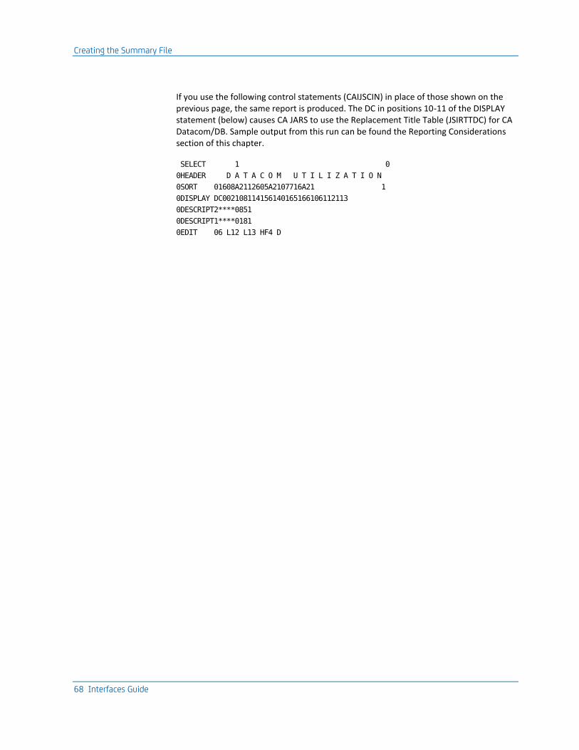
Creating the Summary File
68 Interfaces Guide
If you use the following control statements (CAIJSCIN) in place of those shown on the previous page, the same report is produced. The DC in positions 10-11 of the DISPLAY statement (below) causes CA JARS to use the Replacement Title Table (JSIRTTDC) for CA Datacom/DB. Sample output from this run can be found the Reporting Considerations section of this chapter.
SELECT 1 0
0HEADER D A T A C O M U T I L I Z A T I O N
0SORT 01608A2112605A2107716A21 1
0DISPLAY DC002108114156140165166106112113
0DESCRIPT2****0851
0DESCRIPT1****0181
0EDIT 06 L12 L13 HF4 D

Creating the Summary File
Chapter 2: The Interface to CA Datacom/DB 69
The following sample JCL can be used to produce an CA Datacom/DB Job Charge Detail Report using the Report Writer. It is included as member DCDETR in CAJRJCL.
Sample JCL For CA Datacom/DB Job Charge Detail Report (1 of 2):
//DCDETR JOB ...,CLASS=A,MSGCLASS=A
//*
//*
//* THIS JOB EXECUTES THE CA JARS REPORT PROGRAM TO PRODUCE
//* A CA JARS CA Datacom/DB JOB CHARGE DETAIL REPORT.
//*
//* THE FOLLOWING STATEMENTS ARE INSTALLATION-DEPENDENT
//* AND MUST BE MODIFIED ACCORDINGLY:
//* . JOB ACCOUNTING & CLASS INFORMATION
//* . STEPLIB DSN= CA JARS LOAD LIBRARY
//* . CAIJSHST DSN= CA JARS LEVEL 7 HISTORY FILE
//*
//* SPACE PARAMETERS, APPROPRIATE TO THE SIZE OF YOUR
//* DATA, SHOULD BE USED IN THE 'SORTWK' AND 'CAIJS'
//* STATEMENTS.
//*
//* REFER TO MEMBER DCINTR IN THE CAJRJCL
//*
//JARSSTEP EXEC PGM=JSIMAIN
//STEPLIB DD DSN=CAI.CAJRLOAD,DISP=SHR
//SORTMSG DD SYSOUT=*
//CAIJSPRT DD SYSOUT=*
//CAIJSNAP DD SYSOUT=*
//SYSOUT DD SYSOUT=*
//SYSUDUMP DD SYSOUT=*
//SORTWK01 DD SPACE=(CYL,(1,1)),UNIT=SYSDA
//SORTWK02 DD SPACE=(CYL,(1,1)),UNIT=SYSDA
//SORTWK03 DD SPACE=(CYL,(1,1)),UNIT=SYSDA
//CAIJSCT1 DD SPACE=(CYL,(1,1)),UNIT=SYSDA
//CAIJSCT2 DD SPACE=(CYL,(1,1)),UNIT=SYSDA
//CAIJSACT DD SPACE=(CYL,(1,1)),UNIT=SYSDA
//CAIJSHST DD DSN=CAI.JARS.HISTORY.DATA,DISP=SHR
//CAIJSCIN DD *
SELECT 1 0
0HEADER D A T A C O M J O B C H A R G E D E T A I L
0SORT 01608A2112605A2107716A21 1
0DISPLAY 002108156166144140145146142114
0RATE 1000 100 001001001001001001
0DESCRIPT2****0851
0DESCRIPT1****0181
/*
//
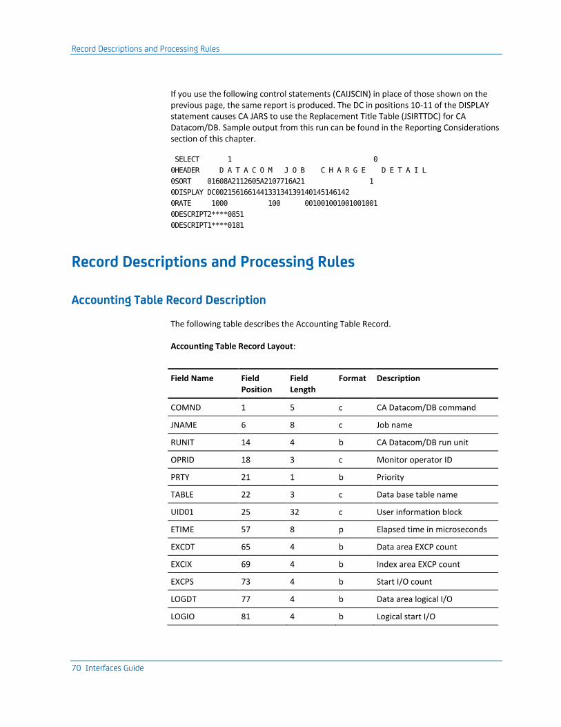
Record Descriptions and Processing Rules
70 Interfaces Guide
If you use the following control statements (CAIJSCIN) in place of those shown on the previous page, the same report is produced. The DC in positions 10-11 of the DISPLAY statement causes CA JARS to use the Replacement Title Table (JSIRTTDC) for CA Datacom/DB. Sample output from this run can be found in the Reporting Considerations section of this chapter.
SELECT 1 0
0HEADER D A T A C O M J O B C H A R G E D E T A I L
0SORT 01608A2112605A2107716A21 1
0DISPLAY DC002156166144133134139140145146142
0RATE 1000 100 001001001001001001
0DESCRIPT2****0851
0DESCRIPT1****0181
Record Descriptions and Processing Rules
Accounting Table Record Description
The following table describes the Accounting Table Record.
Accounting Table Record Layout:
Field Name Field Position
Field Length
Format Description
COMND 1 5 c CA Datacom/DB command
JNAME 6 8 c Job name
RUNIT 14 4 b CA Datacom/DB run unit
OPRID 18 3 c Monitor operator ID
PRTY 21 1 b Priority
TABLE 22 3 c Data base table name
UID01 25 32 c User information block
ETIME 57 8 p Elapsed time in microseconds
EXCDT 65 4 b Data area EXCP count
EXCIX 69 4 b Index area EXCP count
EXCPS 73 4 b Start I/O count
LOGDT 77 4 b Data area logical I/O
LOGIO 81 4 b Logical start I/O

Record Descriptions and Processing Rules
Chapter 2: The Interface to CA Datacom/DB 71
Field Name Field Position
Field Length
Format Description
LOGIX 85 4 b Index area logical I/O
RTIME 89 8 p Run time in microseconds
WTIME 97 8 p Wait time in microseconds
STIME 105 6 c Start time (HHMMSS)
SDATE 111 6 c Start date (YYMMDD)
Format Indicator: b=binary c=character p=packed decimal
Data Element Assignments for CA Datacom/DB
The table below associates a processing rule with each of the fields in the CA JARS record supplied by the CA JARS CA Datacom/DB Interface.
Data Element Assignments For CA Datacom/DB Data:
CA JARS Element Source/Literal Processing Rule ID
CPU ID ' ' 8
File ID '7' 8
Reader Start Date SDATE 2
Reader Start Time STIME 2
Job Name JNAME 1
Job/Step Ind '11' 8
Step Number 3
Processing ID 'C' 8
Record ID ' ' 8
Start Time STIME 2
Start Date SDATE 2
Job Class PRTY 1
Stop Time STIME+ETIME 4
Programmer Name JNAME+RUNIT+OPRID 5
Step Name '*Datacom*' 8
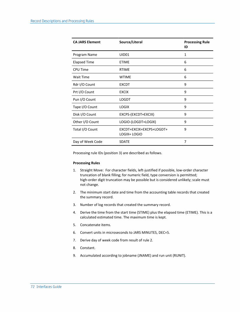
Record Descriptions and Processing Rules
72 Interfaces Guide
CA JARS Element Source/Literal Processing Rule ID
Program Name UID01 1
Elapsed Time ETIME 6
CPU Time RTIME 6
Wait Time WTIME 6
Rdr I/O Count EXCDT 9
Prt I/O Count EXCIX 9
Pun I/O Count LOGDT 9
Tape I/O Count LOGIX 9
Disk I/O Count EXCPS-(EXCDT+EXCIX) 9
Other I/O Count LOGIO-(LOGDT+LOGIX) 9
Total I/O Count EXCDT+EXCIX+EXCPS+LOGDT+ LOGIX+ LOGIO
9
Day of Week Code SDATE 7
Processing rule IDs (position 3) are described as follows.
Processing Rules
1. Straight Move: For character fields, left-justified if possible, low-order character truncation of blank filling; for numeric field, type conversion is permitted; high-order digit truncation may be possible but is considered unlikely; scale must not change.
2. The minimum start date and time from the accounting table records that created the summary record.
3. Number of log records that created the summary record.
4. Derive the time from the start time (STIME) plus the elapsed time (ETIME). This is a calculated estimated time. The maximum time is kept.
5. Concatenate items.
6. Convert units in microseconds to JARS MINUTES, DEC=5.
7. Derive day of week code from result of rule 2.
8. Constant.
9. Accumulated according to jobname (JNAME) and run unit (RUNIT).

Sample Reports
Chapter 2: The Interface to CA Datacom/DB 73
Sample Reports
CA Datacom/DB Interface Reports
The CA Datacom/DB Interface reports are produced from the execution of the Interface from CA JARS to CA Datacom/DB. Two reports are produced:
■ Control Report
■ Termination Report

Sample Reports
74 Interfaces Guide
Samples of these reports are shown next. These reports were obtained by executing a modified version of member DCINTR in CAJRJCL.
CA JARS r12 C A - J A R S / D A T A C O M C O N T R O L R E P O R T CAIDCR00 PAGE 1
Resource Accounting SP0 16 JAN 1998 08
SYSTEM CONTROL CARDS
1...5...10...15...20...25...30...35...40...45...50...55...60...65...70...75...80
Datacom DATA BASE 005 TBLNAM A04 SNAP 25 CPUID D ACCT JSDCACCT
1...5...10...15...20...25...30...35...40...45...50...55...60...65...70...75...80
CAJR922I 1 CONTROL CARD(S) READ.
CA JARS r12 C A - J A R S / D A T A C O M C O N T R O L R E P O R T CAIDCR00 PAGE 2
Resource Accounting SP0 16 JAN 1998 08
CAJR920I 182 TOTAL RECORDS READ, 182 TOTAL RECORDS USED, 0 TOTAL RECORDS UNUSED.
____________________________________________________________________________________________________________________________________
CAJR924I 13 CA JARS HISTORY RECORD(S) WRITTEN.
CAJR904I PROCESSING COMPLETE, RETURN CODE = 0.
CA JARS r12 T E R M I N A T I O N R E P O R T CAIJFR99 PAGE 1
Resource Accounting SP0 16 JAN 1998 08
** PRODUCT RETURN CODE -- 0000
** MESSAGES -- ** NO MESSAGES PRODUCED **
** FILE USAGE --
NAME- CAIJFPR RECORD COUNTS-
ACCESS - SAM 0 -INPUT
BLKSIZE- 00133 27 -OUTPUT
LRECL - 00133 0 -UPDATED
CISIZE - 00000
RECFORM- FIXED ANS-PR-CTL
USAGE - OUTPUT MOVE
SYS - LST
TAP.OPT- NONE
NAME- CAIJFIN RECORD COUNTS-
ACCESS - SAM 1 -INPUT
BLKSIZE- 00080 0 -OUTPUT
LRECL - 00080 0 -UPDATED
CISIZE - 00000
RECFORM- FIXED BLOCKED
USAGE - INPUT MOVE
SYS - 000
TAP.OPT- NONE
NAME- CAIDCS6 RECORD COUNTS-
ACCESS - SAM 0 -INPUT
BLKSIZE- 06233 13 -OUTPUT
LRECL - 00612 0 -UPDATED
CISIZE - 00000
RECFORM- VARIABLE BLOCKED
USAGE - OUTPUT MOVE
SYS - 006
TAP.OPT- STANDARD-LABEL REW-UNLOAD
** START TIME -- 08.58.06 END TIME -- 08.58.14 DURATION -- 00.00.08
** END OF JOB --
HIGHEST RETURN CODE -- 0
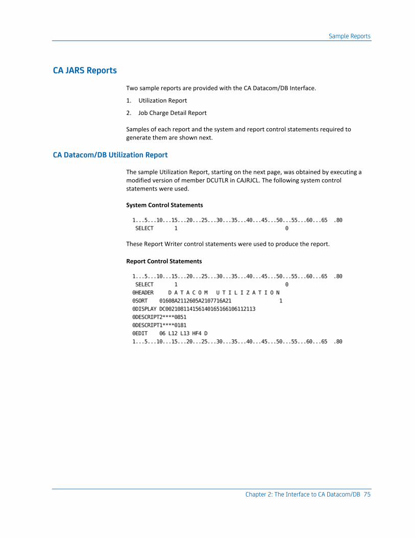
Sample Reports
Chapter 2: The Interface to CA Datacom/DB 75
CA JARS Reports
Two sample reports are provided with the CA Datacom/DB Interface.
1. Utilization Report
2. Job Charge Detail Report
Samples of each report and the system and report control statements required to generate them are shown next.
CA Datacom/DB Utilization Report
The sample Utilization Report, starting on the next page, was obtained by executing a modified version of member DCUTLR in CAJRJCL. The following system control statements were used.
System Control Statements
1...5...10...15...20...25...30...35...40...45...50...55...60...65 .80
SELECT 1 0
These Report Writer control statements were used to produce the report.
Report Control Statements
1...5...10...15...20...25...30...35...40...45...50...55...60...65 .80
SELECT 1 0
0HEADER D A T A C O M U T I L I Z A T I O N
0SORT 01608A2112605A2107716A21 1
0DISPLAY DC002108114156140165166106112113
0DESCRIPT2****0851
0DESCRIPT1****0181
0EDIT 06 L12 L13 HF4 D
1...5...10...15...20...25...30...35...40...45...50...55...60...65 .80

Sample Reports
76 Interfaces Guide
CA Datacom/DB Utilization (1 of 2):
D A T A C O M U T I L I Z A T I O N
BEGIN DATE - 12/27/94 RUN DATE - 01/16/95
END DATE - 12/31/94 PAGE 1
RUN USE TOTAL ELAPSED CPU START START STOP
DESCRIPTION USER INFO UNIT COUNT I/O COUNT TIME TIME DATE TIME TIME
DBTEST01
00591
DBACCOUNT 00591 1 30 00:06:21 00:01:43 94/12/27 20:31:58 20:32:04
1 1 30 00:06:21 00:01:43 94/12/27 20:31:58 20:32:04
00591 1 1 30 00:06:21 00:01:43 94/12/27 20:31:58 20:32:04
00593
DBACCOUNT 00593 1 0 00:00:02 00:00:02 94/12/27 20:25:22 20:25:22
1 1 0 00:00:02 00:00:02 88/12/27 20:25:22 20:25:22
00593 1 1 0 00:00:02 00:00:02 88/12/27 20:25:22 20:25:22
00595
DBACCOUNT 00595 2 27 00:00:56 00:00:46 94/12/27 21:21:09 21:21:09
2 2 27 00:00:56 00:00:46 94/12/27 21:21:09 21:21:09
00595 2 2 27 00:00:56 00:00:46 94/12/27 21:21:09 21:21:09
00652
DBACCOUNT 00652 1 520 00:19:14 00:13:49 94/12/27 22:10:24 22:10:42
1 1 520 00:19:14 00:13:49 94/12/27 22:10:24 22:10:42
00652 1 1 520 00:19:14 00:13:49 94/12/27 22:10:24 22:10:42
00678
DBACCOUNT 00678 1 22 00:00:33 00:00:28 94/01/10 20:38:45 20:38:45

Sample Reports
Chapter 2: The Interface to CA Datacom/DB 77
CA Datacom/DB Utilization (2 of 2):
D A T A C O M U T I L I Z A T I O N
BEGIN DATE - 12/27/94 RUN DATE - 01/16/95
END DATE - 12/31/94 PAGE 2
RUN USE TOTAL ELAPSED CPU START START STOP
DESCRIPTION USER INFO UNIT COUNT I/O COUNT TIME TIME DATE TIME TIME
1 1 22 00:00:33 00:00:28 94/12/27 20:38:45 20:38:45
00678 1 1 22 00:00:33 00:00:28 94/12/27 20:38:45 20:38:45
00679
DBACCOUNT 00679 1 22 00:00:17 00:00:14 94/12/27 20:48:45 20:48:45
1 1 22 00:00:17 00:00:14 94/12/27 20:48:45 20:48:45
00679 1 1 22 00:00:17 00:00:14 94/12/27 20:48:45 20:48:45
00681
DBACCOUNT 00681 1 22 00:09:34 00:06:23 94/12/27 15:55:03 15:55:09
1 1 22 00:09:34 00:06:23 94/12/27 15:55:03 15:55:09
00681 1 1 22 00:09:34 00:06:23 94/12/27 15:55:03 15:55:09
00682
DBACCOUNT 00682 1 22 00:42:09 00:37:33 94/12/27 16:07:08 16:07:50
1 1 22 00:42:09 00:37:33 94/12/27 16:07:08 16:07:50
00682 1 1 22 00:42:09 00:37:33 94/12/27 16:07:08 16:07:50
00683
DBACCOUNT 00683 1 22 00:00:44 00:00:42 94/12/27 18:32:32 18:32:32
1 1 22 00:00:44 00:00:42 94/12/27 18:32:32 18:32:32
00683 1 1 22 00:00:44 00:00:42 94/12/27 18:32:32 18:32:32
00687
®
®
®
DBACCOUNT 00688 2 2,001,473 15:03:49 14:07:06 94/12/27 21:51:35 22:06:35
3 3 2,007,185 27:27:42 20:57:52 94/12/27 20:25:22 22:06:35
00688 3 3 2,007,185 27:27:42 20:57:52 94/12/27 20:25:22 22:06:35
DBTEST01 14 14 2,009,396 29:24:29 22:27:42 94/12/27 15:55:03 22:10:42
CICSPREL
00594
CICSACCOUNT 00594 168 1,870 00:30:53 00:14:34 94/12/27 21:11:03 21:11:33
168 168 1,870 00:30:53 00:14:34 94/12/27 21:11:03 21:11:33
00594 168 168 1,870 00:30:53 00:14:34 94/12/27 21:11:03 21:11:33
CICSPREL 168 168 1,870 00:30:53 00:14:34 94/12/27 21:11:03 21:11:33
182 182 2,011,266 29:55:21 22:42:16 94/12/27 15:55:03 22:10:42

Sample Reports
78 Interfaces Guide
CA Datacom/DB Job Charge Detail Report
The sample Job Charge Detail Report, starting on the next page, was obtained by executing a modified version of member DCDETR in CAJRJCL. The following system control statements were used.
System Control Statements
1...5...10...15...20...25...30...35...40...45...50...55...60...65 .80
SELECT 1 0
These Report Writer control statements were used to produce the report.

Sample Reports
Chapter 2: The Interface to CA Datacom/DB 79
Report Control Statements
1...5...10...15...20...25...30...35...40...45...50...55...60...65 .80
SELECT 1 0
0HEADER D A T A C O M J O B C H A R G E D E T A I L
0SORT 01608A2112605A2107716A21 1
0DISPLAY DC002108156166144140145146142114
0RATE 1000 100 001001001001001001
0DESCRIPT2****0851
0DESCRIPT1****0181
1...5...10...15...20...25...30...35...40...45...50...55...60...65 .80
D A T A C O M J O B C H A R G E D E T A I L
BEGIN DATE - 12/27/94 RUN DATE - 01/16/95
END DATE - 12/31/94 PAGE 1
USE CPU PROCESS TOTAL I/O TOTAL PERCENT RUN
DESCRIPTION USER INFO COUNT TIME CHARGE I/O COUNT CHARGE CHARGE TOTAL UNIT
CICSPREL
00594
CICSACCOUNT 168 00:14:34 $242.75 1,870 $.02 $242.77 1.068 00594
168 00:14:34 $242.75 1,870 $.02 $242.77 1.068 168
00594 168 00:14:34 $242.75 1,870 $.02 $242.77 1.068 168
CICSPREL 168 00:14:34 $242.75 1,870 $.02 $242.77 1.068 168
DBTEST01
00591
DBACCOUNT 1 00:01:43 $28.58 30 $.00 $28.58 .126 00591
1 00:01:43 $28.58 30 $.00 $28.58 .126 1
00591 1 00:01:43 $28.58 30 $.00 $28.58 .126 1
00593
DBACCOUNT 1 00:00:02 $.58 0 $.00 $.58 .003 00593
1 00:00:02 $.58 0 $.00 $.58 .003 1
00593 1 00:00:02 $.58 0 $.00 $.58 .003 1
00595
DBACCOUNT 2 00:00:46 $12.84 27 $.00 $12.84 .057 00595
2 00:00:46 $12.84 27 $.00 $12.84 .057 2
00595 2 00:00:46 $12.84 27 $.00 $12.84 .057 2
00652

Sample Reports
80 Interfaces Guide
D A T A C O M J O B C H A R G E D E T A I L
BEGIN DATE - 12/27/94 RUN DATE - 01/16/95
END DATE - 12/31/94 PAGE 2
USE CPU PROCESS TOTAL I/O TOTAL PERCENT RUN
DESCRIPTION USER INFO COUNT TIME CHARGE I/O COUNT CHARGE CHARGE TOTAL UNIT
DBACCOUNT 1 00:13:49 $230.40 520 $.01 $230.41 1.014 00652
1 00:13:49 $230.40 520 $.01 $230.41 1.014 1
00652 1 00:13:49 $230.40 520 $.01 $230.41 1.014 1
00678
DBACCOUNT 1 00:00:28 $7.64 22 $.00 $7.64 .034 00678
1 00:00:28 $7.64 22 $.00 $7.64 .034 1
00678 1 00:00:28 $7.64 22 $.00 $7.64 .034 1
00679
DBACCOUNT 1 00:00:14 $4.02 22 $.00 $4.02 .018 00679
1 00:00:14 $4.02 22 $.00 $4.02 .018 1
00679 1 00:00:14 $4.02 22 $.00 $4.02 .018 1
00681
DBACCOUNT 1 00:06:23 $106.49 22 $.00 $106.49 .469 00681
1 00:06:23 $106.49 22 $.00 $106.49 .469 1
00681 1 00:06:23 $106.49 22 $.00 $106.49 .469 1
00682
DBACCOUNT 1 00:37:33 $625.87 22 $.00 $625.87 2.754 00682
1 00:37:33 $625.87 22 $.00 $625.87 2.754 1
00682 1 00:37:33 $625.87 22 $.00 $625.87 2.754 1
00683
DBACCOUNT 1 00:00:42 $11.57 22 $.00 $11.57 .051 00683
1 00:00:42 $11.57 22 $.00 $11.57 .051 1
00683 1 00:00:42 $11.57 22 $.00 $11.57 .051 1
00687
DBACCOUNT 1 00:28:09 $469.27 1,524 $.02 $469.29 2.065 00687
1 00:28:09 $469.27 1,524 $.02 $469.29 2.065 1
00687 1 00:28:09 $469.27 1,524 $.02 $469.29 2.065 1
00688
DBACCOUNT 1 06:50:45 $6,845.95 5,712 $.06 $6,846.01 30.126 00688
DBACCOUNT 2 14:07:06 $14,118.44 2,001,473 $20.01 $14,138.45 62.217 00688
3 20:57:52 $20,964.39 2,007,185 $20.07 $20,984.46 92.343 3
00688 3 20:57:52 $20,964.39 2,007,185 $20.07 $20,984.46 92.343 3
DBTEST01 14 22:27:42 $22,461.65 2,009,396 $20.10 $22,481.75 98.934 14
182 22:42:16 $22,704.40 2,011,266 $20.12 $22,724.52 100.002 182

Sample Reports
Chapter 2: The Interface to CA Datacom/DB 81
EXTDATA Reports
There are sample CA Earl and CA Easytrieve reports that will process the Datacom Interface EXTDATA records.
Note: The EXTDATA record layout is described in the chapter "EXTDATA Reporting" in the User Guide.
OPTION LIST OFF
NOTE ******************************************************************
NOTE * REPORT ID: ERXTD001 *
NOTE * REPORT NAME: DATACOM PROCESS REPORT *
NOTE * *
NOTE * DESCRIPTION: THIS WILL REPORT ON THE TOTAL NUMBER OF IOS *
NOTE * AMOUNT OF CPU TIME CONSUMED BY EACH INDIVIDUAL*
NOTE * RUN UNIT ACCESSING DATACOM, SORTED BY JOB NAME*
NOTE * AND ACCOUNTING INFORMATION. *
NOTE * *
NOTE * RECORD TYPES: MRXTHDR, *
NOTE * MRXTSIED *
NOTE * *
NOTE * EXTDATA RECORD: SIED *
NOTE * *
NOTE * MACROS: *
NOTE ******************************************************************
OPTION PRINTER = 132
OPTION PAGE = 60
OPTION PRECISION = ALL
OPTION CPAGE = 60
HISTIN: FILE JARS RECORD=3697
DEF INAREA 1-3697 X
COPY MRXTHDR
COPY MRXTSIED
DEF SESSDATE =RECDATE 1-6 N 'SESSION' 'DATE' PIC '99/99/99'
DEF SESSTIME =RECTIME 1-6 N 'SESSION' 'TIME' PIC '99:99:99'
NOTE ******************************************************************
NOTE * SELECTING FROM HISTORY FILE EXTDATA, SPECIFICALLY SIED *
NOTE ******************************************************************
!
IF PROCID NOT = ':' OR
EXTTYPE NOT = 'SIED'
THEN GOTO START
ENDIF
!
NOTE ******************************************************************
NOTE * REPORT PROCESSING SECTION *
NOTE ******************************************************************
!
REPORT 'DATACOM ACTIVITY SUMMARY'
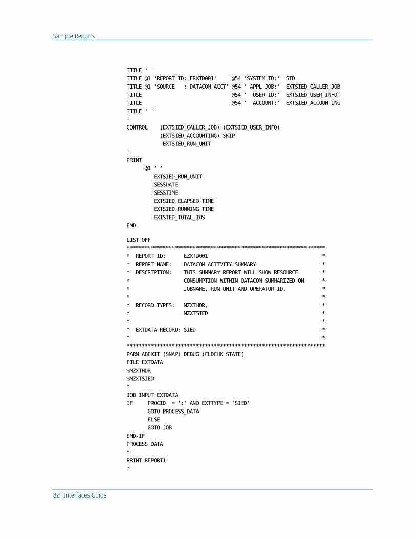
Sample Reports
82 Interfaces Guide
TITLE ' '
TITLE @1 'REPORT ID: ERXTD001' @54 'SYSTEM ID:' SID
TITLE @1 'SOURCE : DATACOM ACCT' @54 ' APPL JOB:' EXTSIED_CALLER_JOB
TITLE @54 ' USER ID:' EXTSIED_USER_INFO
TITLE @54 ' ACCOUNT:' EXTSIED_ACCOUNTING
TITLE ' '
!
CONTROL (EXTSIED_CALLER_JOB) (EXTSIED_USER_INFO)
(EXTSIED_ACCOUNTING) SKIP
EXTSIED_RUN_UNIT
!
@1 ' '
EXTSIED_RUN_UNIT
SESSDATE
SESSTIME
EXTSIED_ELAPSED_TIME
EXTSIED_RUNNING_TIME
EXTSIED_TOTAL_IOS
END
LIST OFF
******************************************************************
* REPORT ID: EZXTD001 *
* REPORT NAME: DATACOM ACTIVITY SUMMARY *
* DESCRIPTION: THIS SUMMARY REPORT WILL SHOW RESOURCE *
* CONSUMPTION WITHIN DATACOM SUMMARIZED ON *
* JOBNAME, RUN UNIT AND OPERATOR ID. *
* *
* RECORD TYPES: MZXTHDR, *
* MZXTSIED *
* *
* EXTDATA RECORD: SIED *
* *
******************************************************************
PARM ABEXIT (SNAP) DEBUG (FLDCHK STATE)
FILE EXTDATA
%MZXTHDR
%MZXTSIED
*
JOB INPUT EXTDATA
IF PROCID = ':' AND EXTTYPE = 'SIED'
GOTO PROCESS_DATA
ELSE
GOTO JOB
END-IF
PROCESS_DATA
*
PRINT REPORT1
*
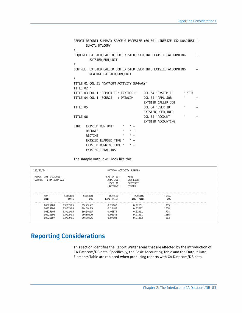
Reporting Considerations
Chapter 2: The Interface to CA Datacom/DB 83
REPORT REPORT1 SUMMARY SPACE 0 PAGESIZE (60 60) LINESIZE 132 NOADJUST +
SUMCTL DTLCOPY
*
SEQUENCE EXTSIED_CALLER_JOB EXTSIED_USER_INFO EXTSIED_ACCOUNTING +
EXTSIED_RUN_UNIT
*
CONTROL EXTSIED_CALLER_JOB EXTSIED_USER_INFO EXTSIED_ACCOUNTING +
NEWPAGE EXTSIED_RUN_UNIT
*
TITLE 01 COL 51 'DATACOM ACTIVITY SUMMARY'
TITLE 02 ' '
TITLE 03 COL 1 'REPORT ID: EZXTD001' COL 54 'SYSTEM ID ' SID
TITLE 04 COL 1 'SOURCE : DATACOM' COL 54 'APPL JOB ' +
EXTSIED_CALLER_JOB
TITLE 05 COL 54 'USER ID ' +
EXTSIED_USER_INFO
TITLE 06 COL 54 'ACCOUNT ' +
EXTSIED_ACCOUNTING
LINE EXTSIED_RUN_UNIT ' ' +
RECDATE ' ' +
RECTIME ' ' +
EXTSIED_ELAPSED_TIME ' ' +
EXTSIED_RUNNING_TIME ' ' +
EXTSIED_TOTAL_IOS
The sample output will look like this:
121/01/04 DATACOM ACTIVITY SUMMARY
REPORT ID: ERXTD001 SYSTEM ID: XE96
SOURCE : DATACOM ACCT APPL JOB: CHARLIEB
USER ID: DATSTART
ACCOUNT: OTHERS
-------------------------------------------------------------------------------------------------------------------------------
RUN SESSION SESSION ELAPSED RUNNING TOTAL
UNIT DATE TIME TIME (MIN) TIME (MIN) IOS
-------------------------------------------------------------------------------------------------------------------------------
00025103 03/12/05 09:49:42 0.25160 0.12551 735
00025104 03/12/05 09:50:05 0.15488 0.05872 1658
00025105 03/12/05 09:50:15 0.06874 0.02411 778
00025106 03/12/05 09:50:20 0.06346 0.01411 1256
00025107 03/12/05 09:50:26 0.07104 0.01463 903
Reporting Considerations
This section identifies the Report Writer areas that are affected by the introduction of CA Datacom/DB data. Specifically, the Basic Accounting Table and the Output Data Elements Table are replaced when producing reports with CA Datacom/DB data.

Reporting Considerations
84 Interfaces Guide
CA Datacom/DB Data Elements
The following is a list of CA Datacom/DB data elements:
Job Name
User Information Block
Priority
Run Unit
Operator ID
Data EXCPs
Index EXCPs
Start I/O
Data Logical I/O
Index Logical I/O
Logical Start I/O
Elapsed Time
CPU Time
Wait Time
Command Count
Minimum Start Date
Minimum Start Time
Maximum End Time
Day of Week Code
User Account Code
Basic Accounting Table
The following table replaces the Basic Accounting Table for designing CA Datacom/DB reports:
Note: The final column in this table provides the corresponding Output Data Element ID for the Basic Accounting Table.
CA Datacom/DB Basic Accounting Table:
Field Name Field Position Field Length F* Notes Output DE ID
CPU Identification 1 1 a 57
Reserved 2-3 2 -
Min Start Date 4-9 6 a YYMMDD 60
Min Start Time 10-15 6 a HHMMSS 61
Job Name 16-23 8 a 04
Reserved 24-25 2 -
Command Count 26-27 2 b 56

Reporting Considerations
Chapter 2: The Interface to CA Datacom/DB 85
Field Name Field Position Field Length F* Notes Output DE ID
Processing ID 28 1 a 'C' 03
Reserved 29-36 8 a
Min Start Time 37-42 6 a HHMMSS 12
Min Start Date 43-48 6 a YYMMDD 06
Job Class 49-50 2 a 07
Max End Time 51-56 6 a HHMMSS 13
Concatenation of Job Name, Run Unit, Operator ID
57-76 20 a 58
User Account Code 77-92 16 a blank unless JOBNAME and OPERID match entry in ACCT table
08
Reserved 93-98 6 -
Record ID 99-106 8 'Datacom' 11
Program Name 107-114 8 a 05
Reserved 115-125 11 -
Job Number 126-130 5 a 14
Priority Level 131-132 2 a 15
Reserved 133-170 38 -
Elapsed Time CPU Time Reserved Wait Time
171-176 177-182 183-188 189-194
6 6 6 6
p p - p
In minutes, to 5 decimal places
25,65 26,66
28,68
Reserved 195-212 18 -
Data EXCPs 213-219 7 p 33
Index EXCPs 220-226 7 p 34
Data Logical I/O 227-233 7 p 35
Index Logical I/O 234-240 7 p 37
Other EXCPs 241-247 7 p 38
Other Logical I/O 248-254 7 p 39
Total I/O Count 255-261 7 p 40
Reserved 262-295 34 -

Contents of Target Libraries
86 Interfaces Guide
Field Name Field Position Field Length F* Notes Output DE ID
Group Code #1 Group Code #2 Group Code #3
296 297 298
1 1 1
a a a
Blank unless filled by grouping feature
84 85 86
Reserved 299-364 66 -
Posted ECBS 365-368 4 p A5
Descriptors Updated 369-372 4 p A6
Reserved 373-417 45 -
CPU Index 418-419 2 p D0
Reserved 420-436 16 -
Day of Week Code 437 1 a D5,D6
Group Code #4 Group Code #5 Group Code #6
438 439 440
1 1 1
a a a
Blank unless filled by grouping feature
D7 D8 D9
Reserved 441-550 108 -
Processor Time 551-556 6 p 999999V99999C; hours
29,69
Processor Charge 557-562 6 p 999999999V99C; dollars
44
I/O Time 563-568 6 p 999999V99999C; hours
30,70
I/O Charge 569-574 6 p 999999999V99C; 45
Reserved 575-584 10
Total Charge 585-590 6 p 999999999V99C 46
Reserved 591-608 18
F* Format Indicator a=alphanumeric b=binary p=packed decimal
Contents of Target Libraries
CAJRSAMP Macros: CAIDC01 DCURT1 DCURT2
CAJRSAMP Sample User Tables: DCAACT
CAJREARL CA EARL Source: MRXTSIED
CAJREZTR CA Easytrieve Source: MZXTSIED

Contents of Target Libraries
Chapter 2: The Interface to CA Datacom/DB 87
CAJROPTN CA Datacom/DB Definitions:
JARSDC1
CAJRJCL Sample JCL: DCINTR DCUTLR DCDETR ASMURT1 ASMURT2
CAJRLOAD Load Modules: JSIRTTDC JSDCPMSG JSDC0000 JSDC1000 DC0100


Chapter 3: The DB2 Interface 89
Chapter 3: The DB2 Interface
The DB2 Interface provides a mechanism for:
■ accounting for DB2 system usage
■ adding DB2 charges to your CA JARS reports
DB2 accounting trace produces that class 1 accounting data that is used to assess and charge DB2 costs. The SMF type 101 records record this data. DB2 does not produce accounting data by default. To specify which accounting data DB2 trace can produce, see the IBM DB2 Installation Guide or Updating DB2 Install and Migration Parameters as described in DB2 System Planning and Administration Guide. In either case, specify the following parameters:
■ YES for TRACE AUTO START. This action assures that the accounting trace is automatically invoked when DB2 is started.
■ YES for SMF accounting.
Once these parameters are set, DB2 trace begins collecting accounting data when a thread connects to DB2. DB2 trace writes a completed record when the thread terminates or when the authorization identifier changes.
Compressed SMF Type 101 records that are decompressed and the DB2 Extract Program (JSZS0000) processes these records. This program is an additional optional feature of the report writer. To activate this program, code a Y (yes) in position 37 of the OPTION statement. In order to avoid multiple passes on the SMF data, activate the exit as part of the routine report program SMF processing procedure. The exit produces two output files; one required and one optional. The required file, ddname CAIJDB2X, contains the DB2 accounting extract for subsequent processing by the Wizard Report Writer. All DB2 accounting data elements from the SMF record are included in the extract record. Therefore, you can use it for more than just chargeback accounting. For instance, you can develop your own CA JARS Wizard programs to monitor:
■ definitional SQL statements usage (CREATE, DROP, and ALTER) by application programs
■ the use of the 32-KB buffer pool
■ DB2 lock contention
The RECFM is FB, the LRECL is 372, and the default BLKSIZE is 2976. BLKSIZE can be overridden on the DD statement to any acceptable BLKSIZE desired.
The optional file, ddname CAIJDB2P, contains a formatted dump of each DB2 accounting record for problem determination purposes. If not used, remove the DD statement; not dummied. The RECFM is VBA, LRECL is 137, and the default BLKSIZE is 1100, but BLKSIZE can be overridden.

Distributed Sample Source Code
90 Interfaces Guide
The interface uses the Wizard Report Writer to read the DB2 extract file. A CA JARS Wizard glossary, CAWGJRD2, is provided for this purpose. Two sample reports, created using CA JARS Wizard, are also provided with the interface. The report samples shown in this chapter are intended to illustrate the use of CA JARS Wizard not how to charge for DB2 usage.
Important! Before CICS Transaction Server (CTS) Release 2.2, double billing for CPU Usage occurs if you use SMF record type 30 and the DB2 Interface. CPU time utilization for a database access is included in the SMF record type 30.
This section contains the following topics:
Distributed Sample Source Code (see page 90) JARSDB21: Debit Record Creation (see page 90) JARSDB22: Sample Report (see page 97)
Distributed Sample Source Code
The first report, JARSDB21, shows how CA JARS debit records can be created. These debit records are read in a run that reports on charges by account. DB2 usage charges are added to the other charges that are calculated on an account basis.
The second report, JARSDB22, is a sample report showing DB2 data usage by authorization ID. Each report is described on the following pages. A description of the CAWGJRD2 glossary and the CA JARS Wizard data element names to use in the CA JARS Wizard programs is contained in the CA JARS Wizard Reference Guide.
The source code for both of these CA JARS Wizard programs is distributed in the AAJ1OPTN distribution library and is copied to CAJROPTN at APPLY time by SMP. You are encouraged to use these as samples and develop your own CA JARS Wizard applications against DB2 data.
Note: If you desire to modify these samples, it is recommended that you copy them to new names outside of CA JARS SMP's control.
JARSDB21: Debit Record Creation
In JARSDB21, CA JARS Wizard is used to:
■ get accounting information for each DB2 user using a DB2 user ID and a CA JARS Wizard facility called file matching. This involves having CA JARS Wizard search a second file to find the accounting information associated with each user ID. Complete information on file matching can be found in the Wizard Reference Guide.

JARSDB21: Debit Record Creation
Chapter 3: The DB2 Interface 91
■ calculate the charge for the user. In this sample the charge is based on CPU time and the number of read requests. Because CA JARS Wizard has a flexible language for computing new fields, and since all the information about the user's session with DB2 is carried in the DB2 account record, the charge can be based on anything in the record. For instance, a surplus could be charged for using DB2 during peak hours.
■ sum the charges for the accounts and print a report that shows the charge by account.
■ write a CA JARS debit record for each account. This debit record contains the account information and the charge that was calculated. All debit records are read in a run that reports on charges by account. The charge for the use of DB2 is added to the other charges that are calculated on an account basis.
JARSDB21 executes on the assumption that you have a secondary file containing one record for each unique DB2 user ID at your site. Each record in this secondary file also contains the necessary debit record accounting information. Report JARSDB21 assumes that the userid is in positions 1 to 8 and the accounting information is in positions 10 to 25, as shown below:
1 2 2
1........0.........0....5
userid accounting info.
If you do not have such a file, you must set one up or alter the JARSDB21 control statements accordingly.
A sample of this file is located CAJROPTN member JARSDBTB.
To execute JARSDB21, set up the necessary JCL for the run. See the CA JARS Wizard Reference Guide for sample JCL. Be sure to include DD statements for the following ddnames:
■ CAIJWI (your DB2 input file)
■ CAIJWI2 (the secondary file containing account information)
■ CAIJWOP (the output file for the debit records)

JARSDB21: Debit Record Creation
92 Interfaces Guide
The following sample report is produced with the debit record output file when JARSDB21 is run.
CA PROGRAM LISTING CA JARS Wizard PAGE 1
CA JARS Wizard 9710JW230 23 MAR 1994 14.41.50
TOTAL CHARGES BY ACCOUNT
CPU TIME READ DB2 ACCOUNT
ACCOUNT TOTAL CHARGE SS.SSS REQUEST RECORDS
---------------- -------------- -------- ------------- -----------
FINANCE $24.12 110.620 227 4
MARKETING $44.81 97.760 2,111 58
NETWORK $34.51 93.080 1,346 4
OPERATIONS $7.43 14.470 378 8
R & D $9.08 17.190 444 163
SALES $13.21 42.560 408 15
.
.
.
TOTAL CHARGES BY ACCOUNT 23 MAR 1994 PAGE 2
CPU TIME READ DB2 ACCOUNT
ACCOUNT TOTAL CHARGE SS.SSS REQUEST RECORDS
---------------- -------------- -------- ------------- -----------
GRAND TOTAL $133.16 375.680 4,914 252

JARSDB21: Debit Record Creation
Chapter 3: The DB2 Interface 93
JARSDB21 Control Statements
PARAMETER XREF NOPC
INPUT CAWGJRD2
*
DEFINE OFILL1(1)(C) = ' '
DEFINE ODEBIT(8)(C) = 'DEBIT '
DEFINE OCPUID(1)(C) = ' '
DEFINE OUSERID(8)(C) = ' '
DEFINE ODATE(6)(C) = ' '
DEFINE OJOB(8)(C) = 'DB2-PROC'
DEFINE OTIME(6)(C) = ' '
DEFINE OPROGRAMMER(20)(C) = ' '
DEFINE ODEBITAMT(6)(P)(.2) = 0
*
DEFINE IOREQT(6)(P) = 0
*
INPUT FILE KEY = 2CC1-8 MATCH = USER/ID TABLE=2CC10-25 LIST
COMPUTE(P) IF MATCHED THEN OACCT(C)(16) EQ 2CC10-25 ELSE
OACCT EQ USER/ID
*
COMPUTE OUSERID EQ USER/ID
COMPUTE IOREQT = (READ/SYNC/BP0 + READ/PREF/BP0 +
READ/SYNC/BP1 + READ/PREF/BP1 +
READ/SYNC/BP2 + READ/PREF/BP2 +
READ/SYNC/BP32 + READ/PREF/BP32)
*
COMPUTE ODEBITAMT = (CPU/TIME * .19283) + (IOREQT * .0123)
ODEBITC (6)(C)(.2) = ODEBITAMT
*
SORT OACCT
BREAK OACCT
HEADING1C TOTAL DB2 CHARGES BY ACCOUNT
LIST(SUM) OACCT(DL) 'ACCOUNT',
ODEBITAMT($) 'TOTAL CHARGE',
CPU/TIME 'CPU TIME',
IOREQT 'READ/REQUEST',
COUNT 'DB2 ACCOUNT/RECORDS'
*
OUTPUT(SUM) FILE,RECFM = FB,R = 80,B = 800,
ITEM = OFILL1,
ODEBIT,
OCPUID,
OUSERID,
OACCT,
ODATE,
OJOB,
OTIME,
OPROGRAMMER,

JARSDB21: Debit Record Creation
94 Interfaces Guide
ODEBITC
JARSDB21 Execution Description
The control statements used in JARSDB21 are described below. Complete descriptions of all CA JARS Wizard control statements can be found in the CA JARS Wizard Reference Guide.
PARAMETER
The PARAMETER control statement specifies options for a CA JARS Wizard run.
XREF
Creates a cross-reference of the data fields used in the run and the statements they are found in. This cross-reference listing is printed in addition to the control statements and the report for the run.
NOPC
Suppresses the CA JARS Wizard error handling routine.
INPUT
INPUT statements are used to identify the CA JARS Wizard glossary and/or the input files for the run. In JARSDB21 two INPUT statements are given:
1. The first INPUT statement lists the CAWGJRD2 glossary as the glossary for the primary input file for the run.
2. The second INPUT statement describes the secondary input file. Secondary files are only used when file matching is to be performed. KEY = 2CC1-8 defines the matching key field for the secondary file. Here, the first eight positions of each record are the matching key. MATCH = USER/ID designates the user ID field of the primary input file as its matching key field.
TABLE indicates that the secondary input file is a table file to be read completely at the start of the run. Therefore, the entire file is available for searching during the run. The field in positions 10 through 25 of the secondary file contains the account information.
The notation 2CC10-25 serves two purposes. It:
■ identifies the location of a data field in the secondary file.
■ serves as a name for the field.

JARSDB21: Debit Record Creation
Chapter 3: The DB2 Interface 95
DEFINE
Ten DEFINE statements are given in JARSDB21. Each defines a field for the run. The first nine DEFINE statements define fields for the debit record. All of the defined fields are initialized each time a new record is processed.
1. OFILL1: One-byte reserved field, initialized as a blank.
2. ODEBIT: Eight-byte field, initialized as DEBIT. This field identifies the statement as a DEBIT statement.
3. OCPUID: One-byte field, initialized as a blank, and used to identify the CPU.
4. OUSERID: Eight-byte field, initialized as blanks, and used for user identification.
5. ODATE: Six-byte field, initialized as blanks, and used for the date (YYMMDD).
6. OJOB: Eight-byte field, initialized as blanks, and used for the job name.
7. OTIME: Six-byte field, initialized as blanks, and used for the time (HHMMSS).
8. OPROGRAMMER: 20-byte field, initialized as blanks, and identifying the programmer.
9. ODEBITAMT: Six-byte field, initialized as zero, and used for the debit amount.
10. IOREQT: Six-byte field used to hold the sum of the READ/SYNC and READ/PREF counts for all buffer pools.
COMPUTE
Four COMPUTE statements are executed in JARSDB21.
The first COMPUTE statement evaluates the file matching between the primary input file and the secondary file. It also defines a new field OACCT (16 bytes) and assigns a value to it based on the results of file matching. If a match occurs on the user ID of a primary input file record and a secondary input file record, OACCT is assigned the value of the account information in positions 10 to 25 of the secondary file. Otherwise, OACCT is assigned a value of UNKNOWN.
Notice the (P) suffix code appended to the first COMPUTE statement. This code indicates that the COMPUTE should take place before the primary input file records are sorted. This is necessary because the SORT occurs on the OACCT field.
The remaining three COMPUTE statements simply assign values to fields: OUSERID, IOREQT, and ODEBITAMT. OUSERID is assigned the value of the user ID in the primary input record. IOREQT and ODEBITAMT are calculated from other fields in the primary input record.

JARSDB21: Debit Record Creation
96 Interfaces Guide
SORT
The SORT statement identifies the sequence in which the input records should be sorted prior to processing. Here the sort is performed on OACCT (the account information). Note that the OACCT field is created and assigned a value in the COMPUTE(P) statement before the SORT.
BREAK
BREAK statements define logical groups of records. Here data is split into groups by OACCT. Records with the same account information are grouped together.
A SORT statement must be included in a CA JARS Wizard run when a BREAK statement is used. The fields specified in the BREAK statement must be included in the SORT statement and must be specified in the same order as the SORT statement.
HEADING
HEADING specifies a title for the report. Here the title for the report (created in addition to the output file) is: TOTAL DB2 CHARGES BY ACCOUNT.
LIST(SUM)
A summary listing is requested along with the output file. Each line of the summary listing lists debit information for a different account. The LIST(SUM) statement identifies the data fields to be summarized and printed. This data includes the:
■ account identifier (information)
■ calculated total charge for the account
■ total CPU time used by the account
■ total number of read requests used by the account
■ number of DB2 accounting records for the account
OUTPUT(SUM)
One summary debit record is produced for each unique account. All records are written to the file identified by ddname CAIJWOP. The OUTPUT statement lists the fields to be summarized and included in each debit record.

JARSDB22: Sample Report
Chapter 3: The DB2 Interface 97
JARSDB22: Sample Report
JARSDB22 is a sample report showing how you can use the CAWGJRD2 glossary and your DB2 input data to create CA JARS reports. A sample of the output from JARSDB22 is shown below
DB2 USAGE BY USER (AUTHORIZATION) ID 23 MAR 1994 PAGE 1
CONNECT CPU SRB
CONNECT TOD USER TIME TIME BP0 BP1 BP2 BP32
DATE HH.MM.SS ID SS.SSS SS.SSS READ READ READ READ
----------- -------- -------- ------- ------- --------- --------- --------- ---------
09 MAR 1994 11.57.43 JAKSU01 .320 .040 0 0 0 0
09 MAR 1994 12.13.32 JAKSU01 .540 .040 0 0 0 0
09 MAR 1994 12.21.12 JAKSU01 .300 .040 0 0 0 0
09 MAR 1994 12.21.51 JAKSU01 .320 .030 0 0 0 0
09 MAR 1994 12.22.55 JAKSU01 .320 .040 5 0 0 0
10 MAR 1994 08.20.27 JAKSU01 .330 .030 1 0 0 0
10 MAR 1994 08.59.03 JAKSU01 .310 .030 0 0 0 0
10 MAR 1994 08.59.32 JAKSU01 .060 .010 0 0 0 0
10 MAR 1994 09.19.22 JAKSU01 .060 0 0 0 0
------- ------- --------- --------- --------- ---------
USER ID TOTAL JAKSU01 2.560 .260 6 0 0 0
01 FEB 1994 10.55.48 KOLFI01 .870 .040 0 0 0 0
01 FEB 1994 10.56.03 KOLFI01 .880 .020 0 0 0 0
.
.
.
DB2 USAGE BY USER (AUTHORIZATION) ID 23 MAR 1994 PAGE 2
CONNECT CPU SRB
CONNECT TOD USER TIME TIME BP0 BP1 BP2 BP32
DATE HH.MM.SS ID SS.SSS SS.SSS READ READ READ READ
----------- -------- -------- ------- ------- --------- --------- --------- ---------
*CONTINUED*
10 MAR 1994 10.37.26 KOLFI01 .120 0 0 0 0
10 MAR 1994 10.37.35 KOLFI01 7.210 .090 120 0 0 0
10 MAR 1994 10.41.59 KOLFI01 5.910 .100 135 0 0 0
------- ------- --------- --------- --------- ---------
USER ID TOTAL KOLFI01 97.760 1.680 2,111 0 0 0
01 FEB 1994 10.47.12 MCFRED .010 0 0 0 0
.
.
.
10 MAR 1994 09.10.25 MCFRED .100 3 0 0 0
10 MAR 1994 09.10.35 MCFRED .100 3 0 0 0
10 MAR 1994 09.10.46 MCFRED .100 3 0 0 0
10 MAR 1994 10.39.44 MCFRED .100 3 0 0 0
10 MAR 1994 10.39.50 MCFRED .100 3 0 0 0
10 MAR 1994 10.39.54 MCFRED .100 3 0 0 0
------- ------- --------- --------- --------- ---------
USER ID TOTAL MCFRED 14.590 .020 436 0 0 0
------- ------- --------- --------- --------- ---------
GRAND TOTAL 375.680 9.290 4,914 0 0 0

JARSDB22: Sample Report
98 Interfaces Guide
JARSDB22 Control Statements
PARAMETER XREF NOPC
INPUT CAWGJRD2
*
SORT USER/ID, CONNECT/DATE, CONNECT/TOD
BREAK USER/ID
HEADING1C DB2 USAGE BY USER (AUTHORIZATION) ID
COMPUTE BP0/READ(6)(P) = READ/SYNC/BP0 + READ/PREF/BP0
COMPUTE BP1/READ(6)(P) = READ/SYNC/BP1 + READ/PREF/BP1
COMPUTE BP2/READ(6)(P) = READ/SYNC/BP2 + READ/PREF/BP2
COMPUTE BP32/READ(6)(P) = READ/SYNC/BP32 + READ/PREF/BP32
LIST CONNECT/DATE, CONNECT/TOD, USER/ID, CPU/TIME, SRB/TIME,
BP0/READ, BP1/READ, BP2/READ, BP32/READ
*
JARSDB22 Execution Description
The control statements used in JARSDB22 are described below. All CA JARS Wizard control statements are fully documented in your CA JARS Wizard Reference Guide.
PARAMETER
The PARAMETER control statement specifies options for a CA JARS Wizard run.
XREF
creates a cross-reference of the data fields used in the run and the statements they are found in. This cross-reference listing is printed in addition to the control statements and the report for the run.
NOPC
suppresses the CA JARS Wizard error handling routine.
INPUT
This INPUT statement lists the CAWGJRD2 glossary as the glossary for the primary input file for the run.
COMPUTE
The four COMPUTE statements in JARSDB22 simply assign values to Buffer Pool Read fields for BP0 through BP32.
SORT
The SORT statement identifies the sequence in which the input records should be sorted prior to processing. Here the sort is performed on USER ID, DATE, and TIME of DAY.

JARSDB22: Sample Report
Chapter 3: The DB2 Interface 99
BREAK
BREAK statements define logical groups of records. Here data is split into groups by user ID. Records with the same USER ID are grouped together.
HEADING
HEADING specifies a title for the report. Here the title for the report (created in addition to the output file) is: DB2 SUMMARY BY USER.
LIST
The LIST statement identifies the data element to be printed. This includes:
■ connect date
■ connect time of day
■ user ID
■ CPU seconds consumed (both TCB and SRB)
■ number of read requests by buffer pool ID


Chapter 4: The IMS Interface 101
Chapter 4: The IMS Interface
The IMS Interface provides data processing managers with a tool to make an effective analysis of IMS activity. The data provided yields a thorough picture of IMS system cost and performance.
Using the IMS Interface you can measure IMS user productivity, monitor the IMS environment, evaluate software efficiency, and provide equitable customer billing and cost distribution.
The interface automatically gathers the information about application resource usage. This information is made available in accounting records on the IMS system log.
Accounting records are reformatted by the interface, producing a summary file, which includes all relevant data in the IMS log record.
The IMS Interface can also be used to generate EXTDATA records that can be processed with the CA EARL and CA Easytrieve report writers. For general information on EXTDATA, see the chapter "EXTDATA Reporting" in the User Guide. Detailed information on how to create EXTDATA is provided later in this chapter.
The interface processes the following IMS log records:
■ Type 01: Message logged
■ Type 03: Message logged
■ Type 07: Accounting
■ Type 31: Message Get-Unique
■ Type 35: Message Enqueue or Re-enqueue
The IMS interface supports IMS releases 1.3 and higher.
This section contains the following topics:
21st Century Support (see page 102) Interface Components (see page 104) The User Accounting Table (see page 105) Interface Operation (see page 109) Interface Commands (see page 112) The Wizard Report Writer (see page 146) Executing the Wizard Report Writer (see page 148) Data Element Directory (see page 174)
21st Century Support
102 Interfaces Guide
21st Century Support
21st Century support for the IMS Interface is provided through maintenance and requires IMS 5.1 or higher. IMS Release 6.1 is IBM's release of IMS that provides century support in the IMS Log File's date fields in Julian YYYYDDD form.
The interface has been modified to support the new IMS date format (IMS 6.1 and above), while input parameters and the output history file retain their existing date formats. Internally, the interface processes and sorts based on the full century date, so date selection and sort sequencing will be correct. The overall design of 21st century support in the Report Writer is to treat years with values of 00 through 59 as being in the 21st century; for example, 2000-2059. Years with values of 60 through 99 are treated as being in the 20th century; for example, 1960-1999. The following text discusses in detail each of the areas of date processing affected by 21st century support.
For purposes of sorting, comparisons and calculations involving dates, the two-digit year is logically expanded to include the century. This ensures proper sort sequencing, correct comparisons and results from calculations involving dates.
However, externally the two-digit year is maintained. This includes all external files with the exception of EXTDATA files, reports, and input parameters. This implementation eliminates the need to change parameters or file layouts. In addition, the Wizard Report Writer has been modified in the same fashion to properly process two-digit years in date fields.
The following text discusses in detail each of the areas of date processing affected by 21st century support.
Sorting on Date Fields
When a date field is specified on the Sort Control Statement, CA JARS takes the century into account and makes an adjustment in setting up the Sort field. If the year is 59 or less, it is treated as being in the 21st century. If the year is 60 or higher, it is treated as being in the 20th century. Thus, when performing a sort in ascending sequence, this product sorts a YY/MM/DD field containing "99/12/31" (December 31, 1999) ahead of a field containing "00/01/01" (January 1, 2000).
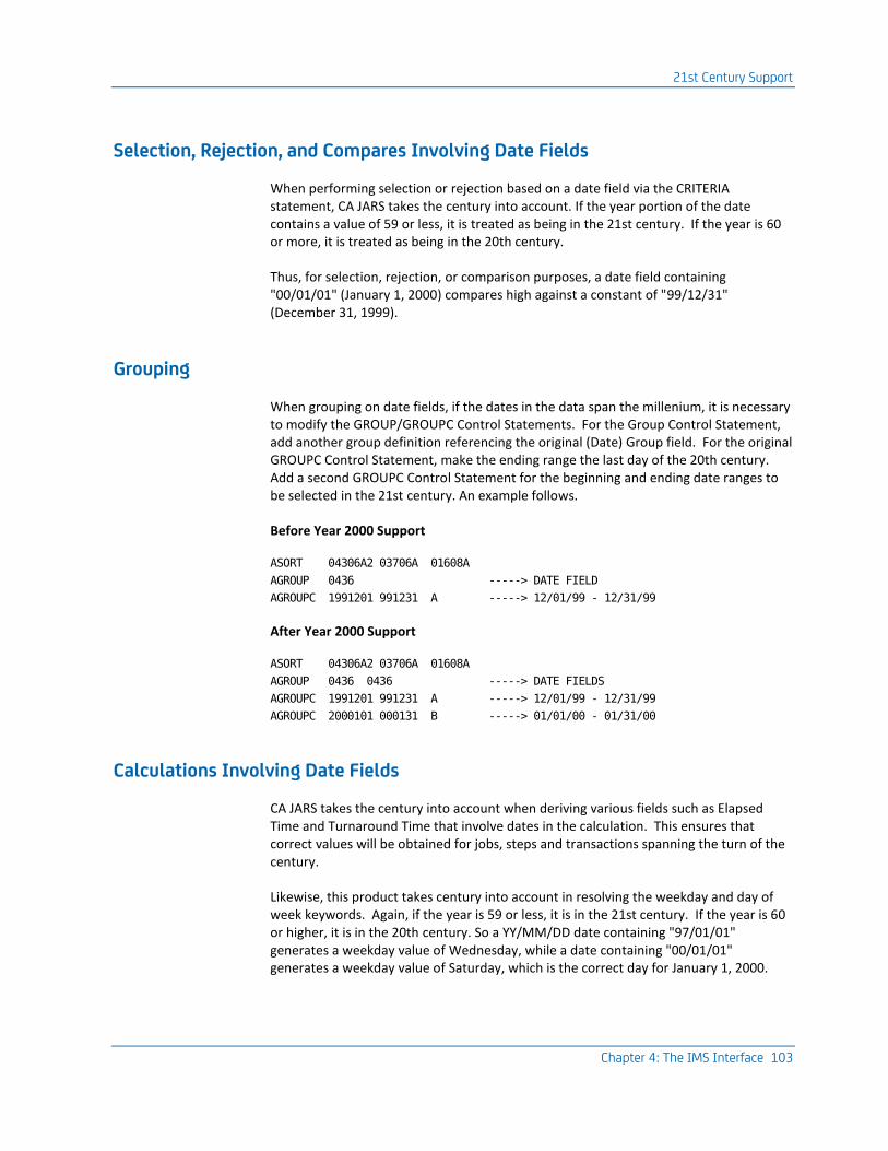
21st Century Support
Chapter 4: The IMS Interface 103
Selection, Rejection, and Compares Involving Date Fields
When performing selection or rejection based on a date field via the CRITERIA statement, CA JARS takes the century into account. If the year portion of the date contains a value of 59 or less, it is treated as being in the 21st century. If the year is 60 or more, it is treated as being in the 20th century.
Thus, for selection, rejection, or comparison purposes, a date field containing "00/01/01" (January 1, 2000) compares high against a constant of "99/12/31" (December 31, 1999).
Grouping
When grouping on date fields, if the dates in the data span the millenium, it is necessary to modify the GROUP/GROUPC Control Statements. For the Group Control Statement, add another group definition referencing the original (Date) Group field. For the original GROUPC Control Statement, make the ending range the last day of the 20th century. Add a second GROUPC Control Statement for the beginning and ending date ranges to be selected in the 21st century. An example follows.
Before Year 2000 Support
ASORT 04306A2 03706A 01608A
AGROUP 0436 -----> DATE FIELD
AGROUPC 1991201 991231 A -----> 12/01/99 - 12/31/99
After Year 2000 Support
ASORT 04306A2 03706A 01608A
AGROUP 0436 0436 -----> DATE FIELDS
AGROUPC 1991201 991231 A -----> 12/01/99 - 12/31/99
AGROUPC 2000101 000131 B -----> 01/01/00 - 01/31/00
Calculations Involving Date Fields
CA JARS takes the century into account when deriving various fields such as Elapsed Time and Turnaround Time that involve dates in the calculation. This ensures that correct values will be obtained for jobs, steps and transactions spanning the turn of the century.
Likewise, this product takes century into account in resolving the weekday and day of week keywords. Again, if the year is 59 or less, it is in the 21st century. If the year is 60 or higher, it is in the 20th century. So a YY/MM/DD date containing "97/01/01" generates a weekday value of Wednesday, while a date containing "00/01/01" generates a weekday value of Saturday, which is the correct day for January 1, 2000.

Interface Components
104 Interfaces Guide
Interface Components
The interface executes as a batch program and is distributed to users in object form on a system distribution tape. The interface program reads the IMS log, and employs a User Accounting Table to identify various transactions with users. Selected records are reformatted for input to the CA JARS Report Writer.
Input to the interface program is the IMS log file. Output is a level-5 summary (history) file. Optionally, you can also request an EXTDATA output file.
The following table shows the Target library location of supplied sample source and JCL members:
JSIUA CAJRMAC User Accounting Macro
JSIRTTMS CAJRSAMP IMS Interface Title Table
IMSJARS CAJRJCL Sample Working Set Report JCL
IMSTRAN CAJRJCL Sample IMS Interface Translate JCL
IMSUA CAJRJCL Sample IMS Interface User Accounting JCL
User Accounting Table
The IMS Interface translates IMS log data into the format required for the Report Writer. One part of the operation of the interface is to add user-defined cost center identification to each translated record. This is accomplished using a User Accounting Table.
The User Accounting Table is a valuable part of the interface program. It causes specified transaction identifiers to be associated with given user identification text that is added to the translated record. You can create a unique User Accounting Table tailored to the accounting standards and needs of your installation.
The User Accounting Table can be created during IMS translation by specifying the two-character link-edited accounting table suffix on the TRANSLATE control statement.
User Accounting Table Macro
To build a User Accounting Table, you must assemble a set of JSIUA macro statements that generate Assembler Language instructions. This table is then used by interface program JSIIMT00 to reformat the IMS records for the Report Writer. The JSIUA macro is included on the system distribution tape and can be found in CAJRMAC.
Working Set Reports
A standard set of selected working set reports on IMS activity can be produced by the Report Writer. The required control statements are included on the system distribution tape and can be found in CAJRJCL member IMSJARS.

The User Accounting Table
Chapter 4: The IMS Interface 105
COMPRESS Options
As the IMS data contains a large number of accounting records (IMS type 7 records only), the IMS Interface Interface provides a facility through which you can reduce the number of records. This is achieved by compressing the IMS account type to a smaller amount of data.
Output data can be compressed further by using the INTERVAL parameter of the COMPRESS command. The time INTERVAL specified causes all data from like transaction IDs to be combined into one record without any loss of data detail.
The User Accounting Table
The IMS Interface translates IMS data into Report Writer format and can assign a cost center identification to each record. This cost center identification is accomplished using a User Accounting Table. The IMS Interface scans the User Accounting Table for an entry whose transaction ID matches the data element value in the IMS log record.
The IMS Interface examines the transaction ID in each User Accounting Table entry, in order, from the beginning to the end of the table. The user accounting information from the first table entry found to match the record is inserted into the output record. If no match is found, the output user accounting information field contains blanks.
A blank (nonspecified) value for the transaction ID in a table entry is ignored for comparison, and therefore treated as a matching identifier. An asterisk (*) in any position of a table entry is treated as matching the corresponding position in the record identifier(s).
Example
Suppose an IMS log record has the following value for its transaction ID:
Transaction
ABCDEFGH

The User Accounting Table
106 Interfaces Guide
All of the following identifiers for User Accounting Table entries would match the basic record:
Transaction
ABCDEFGH
ABCDEFG*
ABCDEF**
ABC*****
***D****
(and so on)
Note: The user accounting information from the first User Accounting Table entry found to match the input record is used.
The User Accounting Table is built by assembling a set of JSIUA macro instructions. JSIUA macro instructions are written in Assembler Language. Follow the rules for coding Assembler Language macro statements when using the JSIUA macro. Object code is generated as the statements are processed.
If serious errors in the macro specification are detected, a message is issued and assembly continues even though the assembled module may not produce the intended results.
Creating a User Accounting Table
The interface program translates IMS log data into the format for the Report Writer. One part of the operation of the interface is to add user-defined cost center identification to each translated record.

The User Accounting Table
Chapter 4: The IMS Interface 107
The interface accomplishes this cost center identification using the User Accounting Table. Assemble the User Accounting Table with the following JCL, found in CAJRJCL member IMSUA.
//IMSUA JOB (ACCTINFO),'PROGRAMMER INFO',
// MSGCLASS=X,CLASS=A
//*
//*********************************************************************
//* PURPOSE: TO ASSEMBLE AND LINK THE USER ACCOUNTING TABLE FOR
//* PURPOSE: THE CA JARS IMS INTERFACE.
//*********************************************************************
//IMSUA EXEC ASMA90
//*
//ASM.SYSLIB DD DISP=SHR,DSN=CAI.CAJRMAC CA JARS INSTALL MACLIB
// DD DISP=SHR,DSN=SYS1.MACLIB
//ASM.SYSIN DD *
JSIUA TYPE=INITIAL
.
.
.
Code JSIUA statements for your configuration.
See 'User Accounting Table (Optional)'
.
.
.
JSIUA TYPE=FINAL
END
/*
//* THE LAST 2 BYTES OF LOAD MODULE NAME ARE SUFFIX.
//* THIS WILL BE SPECIFIED ON THE TRANSLATE CONTROL STATEMENT WHEN
//* YOU RUN THE CA JARS IMS INTERFACE PROGRAM, JSIIMT00.
//*
//LKED.SYSLMOD DD DISP=SHR,DSN=CAI.your.loadlib(JSIIMUxx) <<< DSN
//
Note: The xx in the SYSLMOD data set member name is the load module suffix.
Initializing the User Accounting Table
The User Accounting Table is built by specifying a set of coded JSIUA macro statements. The JSIUA TYPE=INITIAL macro must be coded first, followed by JSIUA TYPE=ENTRY macros, and terminated by a JSIUA TYPE=FINAL macro.
The following can be coded on the JSIUA macro statement:
JSIUA TYPE=INITIAL

The User Accounting Table
108 Interfaces Guide
TYPE=INITIAL
specifies that this statement begins the User Accounting Table assembly.
Defining a User Accounting Table Cost Center Entry
Use the JSIUA TYPE=ENTRY statement to define a User Accounting Table cost center entry within the User Accounting Table.
There can be any number of JSIUA TYPE=ENTRY statements coded for the User Accounting Table assembly, including none (dummy table). If there is more than one TYPE=ENTRY statement in the assembly, the corresponding User Accounting Table entries are generated in the order that the assembler encounters the statements.
The following parameters can be specified for JSIUA TYPE=ENTRY:
JSIUA [TYPE=ENTRY,]
ITRANS=cccccccc,
USER='cccccccccccccccc'
TYPE=ENTRY
specifies that an entry is being defined in the User Accounting Table. This parameter and the first comma normally following it may be omitted.
ITRANS=cccccccc
specifies the 1-8 character transaction identifier of transactions whose execution is to be attributed to the cost center defined in this table entry.
USER='cccccccccccccccc'
specifies the 1-16 character cost center identification that will be placed in the user accounting information field of the interface's output records.
Terminating a User Accounting Table
The assembly of the IMS Interface Interface User Accounting Table is terminated when the assembler encounters the JSIUA TYPE=FINAL macro statement. This statement must be the last assembler statement in the assembler input before the END card for this User Accounting Table assembly.
The TYPE=FINAL statement causes assembler statements necessary for proper table length calculations to be generated. It can also add one last entry to the User Accounting Table. This last entry has a blank identifier field, and therefore, matches all otherwise unmatched input records.

Interface Operation
Chapter 4: The IMS Interface 109
The following parameters can be specified for JSIUA TYPE=FINAL:
JSIUA TYPE=FINAL
[,USER='cccccccccccccccc']
TYPE=FINAL
specifies that this statement terminates the User Accounting Table.
USER='cccccccccccccccc'
specifies the 1-16 character cost center identification associates with blank identifiers, generated as the last entry in the table.
Interface Operation
The IMS Interface translates IMS log data from its data collection format to the input format required for the Report Writer. The interface uses the IMS log data set as input.
Output from the interface typically occupies a small fraction of the tape that the input IMS data occupies.
The interface has the ability to compress the IMS log tape. It only translates IMS accounting records. Using the compress function causes only these records to be copied to an output data set.
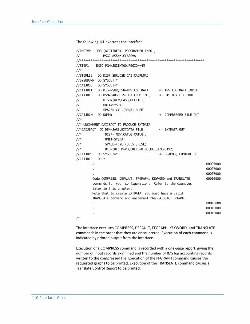
Interface Operation
110 Interfaces Guide
The following JCL executes the interface.
//IMSIVP JOB (ACCTINFO),'PROGRAMMER INFO',
// MSGCLASS=X,CLASS=A
//*********************************************************************
//STEP1 EXEC PGM=JSIIMT00,REGION=4M
//*
//STEPLIB DD DISP=SHR,DSN=CAI.CAJRLOAD
//SYSUDUMP DD SYSOUT=*
//CAIJRSO DD SYSOUT=*
//CAIJRII DD DISP=SHR,DSN=IMS.LOG.DATA <- IMS LOG DATA INPUT
//CAIJRIO DD DSN=JARS.HISTORY.FROM.IMS, <- HISTORY FILE OUT
// DISP=(NEW,PASS,DELETE),
// UNIT=SYSDA,
// SPACE=(CYL,(30,5),RLSE)
//CAIJRCM DD DUMMY <- COMPRESSED FILE OUT
//*
//* UNCOMMENT CAIJSACT TO PRODUCE EXTDATA
//*CAIJSACT DD DSN=JARS.EXTDATA.FILE, <- EXTDATA OUT
//* DISP=(NEW,CATLG,CATLG),
//* UNIT=SYSDA,
//* SPACE=(CYL,(30,5),RLSE)
//* DCB=(RECFM=VB,LRECL=8188,BLKSIZE=8192)
//CAIJRPR DD SYSOUT=* <- GRAPHS, CONTROL OUT
//CAIJRCD DD *
. 00007000
. 00007000
. 00007000
Code COMPRESS, DEFAULT, FFGRAPH, KEYWORD and TRANSLATE 00010000
commands for your configuration. Refer to the examples
later in this chapter.
Note that to create EXTDATA, you must have a valid
TRANSLATE command and uncomment the CAIJSACT DDNAME.
. 00013000
. 00013000
. 00013000
/*
The interface executes COMPRESS, DEFAULT, FFGRAPH, KEYWORD, and TRANSLATE commands in the order that they are encountered. Execution of each command is indicated by printed output from the interface.
Execution of a COMPRESS command is recorded with a one-page report, giving the number of input records examined and the number of IMS log accounting records written to the compressed file. Execution of the FFGRAPH command causes the requested graphs to be printed. Execution of the TRANSLATE command causes a Translate Control Report to be printed.

Interface Operation
Chapter 4: The IMS Interface 111
The Control Report
The IMS Interface prints a Control Report upon successful execution of a TRANSLATE command. The NORMAL END OF PROCESSING message immediately follows this report.
The Control Report shows total counts of all records processed by the interface. The following statistics are shown:
IMS RECORDS READ
Number of valid type 07 accounting records.
RECORDS REJECTED
Number of type 07 accounting records rejected, primarily because of invalid date/time fields.
JARS JOB RECORDS WRITTEN
Number of translated records created from the input data.
EXTDATA RECORDS WRITTEN
Number of EXTDATA records written to the CAIJSACT DD.
The interface requires several interrelated files to execute. The following list describes these data sets and their functions:
DDName Description
STEPLIB Describes the load library that was loaded from the distribution tape.
SYSUDUMP Describes a SYSOUT data set for dump output in the case of an abnormal termination.
CAIJRSO The output file that contains SNAP OUTPUT IMS records.
CAIJRII Describes the input file to be processed by the IMS Interface. The input log record includes: Type 01, 03, 07, 31, and/or 35.
CAIJRIO Describes a data set for the translated output file.
CAIJRCM Describes a data set for the compressed output file.
CAIJRPR Describes the SYSOUT data set for generated display messages.
CAIJRCD Describes the interface commands to be executed. Valid commands are COMPRESS, DEFAULT, FFGRAPH, KEYWORD and TRANSLATE.

Interface Commands
112 Interfaces Guide
Interface Commands
The IMS Interface provides several valuable graphic reports as optional printed output. These reports can be requested and customized to meet your needs using a flexible interface command language. Interface commands are entered through card image input to the interface. An output tape to be used as input to the Report Writer can also be produced using the TRANSLATE control command.
EXTDATA may also be produced by including a CAIJSACT DD and providing a TRANSLATE command.
Interface Command Format
The interface command language is a free-format command and parameter input language somewhat similar in structure to the IBM assembler macro statement coding format. To code a Interface command use the following fields:
Position Field Name Notes
1 Label 1 to 8 character label.
2-18 Command The command must start and end between positions 2 and 18.
10-71 Parameters Parameters (if present) must start and end in these positions.
72 Blank Not used
73-80 Blank Used for card sequence numbers as needed.

Interface Commands
Chapter 4: The IMS Interface 113
Commands include: COMPRESS, DEFAULT, FFGRAPH, KEYWORD and TRANSLATE.
Comments can be given with an asterisk (*) in position one. Labels must begin in position one and can be specified alone. Continuation is indicated by a comma as the last character in the parameters field followed by a space as a delimiter. Continuations resume after position ten of the next line. If only the command is entered, defaults are used for the operands. The commands are read by the interface through ddname CAIJRCD.
When using the interface command language, the following rules must be followed:
1. The first four characters of a parameter can be used to identify the parameter.
2. If more than one value is entered for a parameter, use parentheses to enclose the values and commas to separate the values. A value list can continue to the next line.
3. When entering text use single quotes to enclose the string if blanks are embedded in the text. Text cannot be continued on the next card.
COMPRESS Command
The IMS Interface requires an abbreviated log tape to:
■ generate graphs with the FFGRAPH command
■ create a data set for the Report Writer using the TRANSLATE command
Use the COMPRESS command to create this abbreviated version of the IMS log tape.
The abbreviated log tape contains only type 07 records. It considerably reduces the volume of useful data that may be retained for extended analysis. It also reduces interface run time for subsequent passes of the data.
If the COMPRESS command is encountered with the first set of TRANSLATE and FFGRAPH commands, subsequent sets of TRANSLATE and FFGRAPH commands use the compressed file as input instead of the raw IMS log data set. Therefore, it is efficient to include a COMPRESS command in the first command set of a multiple command set run, even if the compressed file is not to be retained.
The compressed file is written to the data set specified by the CAIJRCM ddname. If no COMPRESS command is given to the interface, the ddname CAIJRCM is not referenced. If a COMPRESS command is executed, subsequent command sets in the same interface execution use the compressed file as input, through the CAIJRCM ddname, and the CAIJRII ddname is not read from again.

Interface Commands
114 Interfaces Guide
The INTERVAL Parameter
The INTERVAL= parameter of the COMPRESS command can further reduce the amount of data output by the interface. Specification of a time interval value (in minutes) causes the data for all like transaction IDs (occurring over the specified interval) to be accumulated in one output record.
The format for the COMPRESS command is:
2 (command position)
COMPRESS INTERVAL=0
nn
nn
This is the compress time interval desired in minutes. Specification of 0 (the default) causes one record to be output for each IMS type 07 accounting record.
Example
2 (command position)
COMPRESS INTERVAL=15
This command causes an abbreviated version of the input log tape to be generated. Data with like transaction IDs occurring in 15 minute intervals is compressed into one interval output record.
Only one COMPRESS command is processed per interface execution.

Interface Commands
Chapter 4: The IMS Interface 115
DEFAULT Command
The IMS Interface can process several different releases of IMS log data. Code the DEFAULT command as the first command in CAIJRCD, indicating the release of IMS log data to be processed.
Command Operands
[LABEL] DEFAULT
[,RELEASE={ 7.1.0 } ]
[ { 8.1.0 } ]
[ { 9.1.0 } ]
[ {10.1.0 } ]
[ { . } ]
[ { . } ]
[ { . } ]
RELEASE=
specifies the IMS release of the log data which is input this run. The default release is 3.1.0.
DEFAULT RELEASE=3.1.0
FFGRAPH Command
The FFGRAPH command controls the generation of Resource Utilization Graphs (RUGs). These graphs show how IMS resources are being used. The graphs can show peak use by day, week, and even month. This capability gives the manager a picture of how the IMS resources are being used (such as DL/1 database access counts or CPU time).
Types of Resource Utilization Graphs
The Resource Utilization Graph set consists of several different graphs, including the DAILY, COMPOSITE, SUMMARY, CALENDAR, and Named Resource reports.
The DAILY report shows resources requested by time intervals for a 24-hour period. With this graph you can see your peak periods within the day and how they relate to other resources.
The COMPOSITE report graphs the average of a resource by time interval, averaged over a period of days. With this graph, you are shown on an average how IMS resources are used over a daily period.

Interface Commands
116 Interfaces Guide
The SUMMARY report displays the maximum or average periods for a day against the maximum or averages from other days. This gives you a summary of how the resource is saturated over a number of days.
The CALENDAR report is used to relate resources used during a day against other days of the week or month.
Named Resource reports can be used to graph PSB name, transaction, job name, step name, region protection key and type, and Message Processing Region/Batch Processing Region activity by comparing their use against one another.
Resource Utilization Graph Command Language
Since Resource Utilization Graphs are also a part of the interface, the graphs are requested by using the FFGRAPH command. This command allows you to pick options such as the variables for each plot, which graphs to display, and transactions to be selected.
FFGRAPH Examples
The following are examples of the structure of the FFGRAPH command. The next section, FFGRAPH Format, describes the format of the command.
The simplest input is the command alone. This causes the RUG graphs to use the predefined defaults such as report selection and time interval.
2 (command position)
FFGRAPH
To select a specific transaction to graph across a span of days, the command would be entered as follows:
2 10
FFGRAPH FROM=84319,TO=84320,TRANSID=LOGO,
DAILY=OFF,COMPOSITE, SUMMARY,
CALENDAR=BOTH
A CALENDAR graph is very versatile because it can display the selected fields in different orders. For example:
2 10
FFGRAPH DAILY=OFF,SUMMARY=OFF,COMP=OFF,
SYSPLOT=NONE,CALENDAR=(ALL,CBA,BOTH)
This command causes four separate CALENDAR reports to be printed. ALL displays all the fields on the calendar. CBA displays only those fields and in that order on the calendar. BOTH is used to create one calendar report for each variable selection, one with the maximum and one with the average values for the interval on the calendar.

Interface Commands
Chapter 4: The IMS Interface 117
To select graphs other than the defaults, specify override parameters on the commands, as in the following example:
2 10
FFGRAPH NEWPLOT=CPU,
NEWPLOT=(TRANSACT,MESSAGES),
SYSPLOT=AGKLM,
SUMMARY=OFF,
CALENDAR=OFF,COMPOSITE=OFF
CPU MAXVAL=29999
The last line sets the maximum to plot the graph of the keyword CPU.
A translated file can be generated and resource utilization graphs can be run at the same time:
2 10
FFGRAPHH TO=84320
TRANSLATE SUFFIX=XX
Multiple sets of Resource Utilization Graphs can be generated from one interface execution:
2 10
FFGRAPH TO=84320
FFGRAPH TO=84319,SUMMARY=OFF,
CALENDAR=OFF,COMPOSITE=OFF
FFGRAPH SUBSET=PSB-NAME

Interface Commands
118 Interfaces Guide
FFGRAPH Format
The following is the format of the FFGRAPH command.
Command Operands
[LABEL] FFGRAPH
[ [ [ {ON } ] ] ]
[ [ [ {OFF }, ] ] ]
[ [ [ {MAX } ] ] ]
[,CALENDAR =( [ [ {AVG } , ] ] ) ]
[ [ [ {BOTH} ] ] ]
[ [ ] ]
[ [ [ {ALL } ] ] ]
[ [ [ {A,B,C, ,H} ,] ] ]
[ [ ] ]
[ [ [NOLEGEND , ] ] ]
[ [ ] ]
[ [ [BAR=I, ] ] ]
[,COLLAPSE = ON ]
[,COMPOSITE = {ON } ]
[ {OFF} ]
[,DAILY = {ON } ]
[ {OFF} ]
[,EXPAND = {ON } ]
[ {OFF} ]
[,FOOTER = {ON } ]
[ {OFF} ]
[,FROM = {YYDDD } ]
[ {(YYDDD,HHMM)} ]
[,HEADER = '____ up to 60 char ____' ]
[,NEWPLOT = {KEY1 } ]
[ {(KEY1,KEY2)} ]
[,REGION = {MPR} ]
[ {BPR} ]
[,SELECT = {NAME1 } ]
[ {(NAME1,NAME2,...,NAME25)} ]
[ {30 } ]
[,SPAN = {10-90 } ]
[ {1440 or TOTAL} ]

Interface Commands
Chapter 4: The IMS Interface 119
[,START = {HHMM} ]
[ {0000} ]
[ [ {TIME } ] ]
[ [ ] ]
[ [ {index-name } ] ]
[ [ ] ]
[ [ {field-group-identifier } ] ]
[ [ ] ]
[,SUBSET=[ {(index-name,BY,field-group-identifier)} ] ]
[ [ ] ]
[ [ [ A ] ] ]
[ [ [ B ] ] ]
[ [ [ C ] ] ]
[ [ [ D ] ] ]
[ [ [,SORT = E ] ] ]
[ [ [ F ] ] ]
[ [ [ G ] ] ]
[ [ [ H ] ] ]
[ [ [ NAME ] ] ]
[ [ ] ]
[ [ [,SMOOTH ] ] ]
[ {ON } ]
[ {OFF } ]
[,SUMMARY = {BOTH} ]
[ {MAX } ]
[ {AVG } ]
[ {ALL } ]
[ {NONE } ]
[,SYSPLOT = {V } ]
[ {(A,B,C,...,Z)} ]
[ {(ABCDEF) } ]
[,TO = {YYDDD } ]
[ {(YYDDD,HHMM)} ]
[,TRANSID = {AAAA } ]
[ {(AAAA,BBBB,....,HHHH)} ]
CALENDAR=
is specified to request the CALENDAR report. MAX is a calendar of the maximums for any time interval of each day. The AVG is the average of all time intervals for each day. BOTH generates both AVG and MAX reports.

Interface Commands
120 Interfaces Guide
Data elements shown on the CALENDAR report can be specified by the report ID entered for a report. For example, if ALL is entered, all fields are displayed; if ABCG is entered, only these fields are displayed. NOLEGEND removes the legend at the bottom of each CALENDAR. BAR= is used to specify a character to replace the vertical I in the CALENDAR report. Up to 10 different CALENDAR reports can be requested with one run.
COLLAPSE=
is specified to collapse null lines out of a graph. If there is no data to display for three or more intervals, the message *NO DATA* is shown, instead of several intervals having zero values if (the default) ON is specified.
COMPOSITE=
is specified to request the COMPOSITE report.
DAILY=
is specified to request the DAILY report.
EXPAND=
causes a single-element graph to be printed using full-page width. Otherwise, a single-element graph uses only about half a page width.
FOOTER=
is used to request tic lines at the bottom of each page.
FROM=
FROM is used to find the report starting point in the file to begin the report. YYDDD is the Julian date to begin. HHMM is the hour and minute to start. If this parameter is omitted, the beginning of the file is the starting point.
Julian dates specified with a year value of 00 through 59 are treated as year 2000 through 2059, and are considered logically greater than year values of 60 through 99 (1960 through 1999).
HEADER=
is used to enter a new header on each page of the reports. The new header can be up to 60 characters and is automatically centered in the header line.
NEWPLOT=
is used to create user plots if they are not one of the predefined SYSPLOTs (see the SYSPLOT parameter). The keywords are used to select data elements (one or two) to be graphed. The following example creates two plots:
NEWPLOT=CPU
NEWPLOT=(TRANSACT,CPU)
The first plots the CPU time and the second plots transactions and CPU time.

Interface Commands
Chapter 4: The IMS Interface 121
REGION=
is used to select the records associated with a Message Processing Region (MPR) or Batch Message Processing Region (BPR). Only IMS log records for applications run in the associated region are considered for Resource Utilization Graph generation.
SELECT=
if SUBSET is used for a named facility (such as PSB-NAME), SELECT can be used to select up to 25 items for the report. Each item may be a facility name, or a facility name prefix preceded with a slash (/). For example, SELECTing on the name APPL1 causes only data associated with PSB-NAME APPL1 to be graphed. SELECTing /APPL accepts data associated with any PSB-NAME beginning with the letters APPL, such as APPL1, APPLB, or APPL1234.
SPAN=
SPAN is used to control the time interval used by a graph. The interval of time which represents one line on the DAILY and COMPOSITE graph can be from 10 to 90 minutes; the default is 30 minutes. A value of 1440 may be specified if no DAILY or COMPOSITE graph is requested. If 1440 is used, the SUMMARY and CALENDAR graphs represent a daily total of each field entered. The DAILY and COMPOSITE graphs are automatically turned off. TOTAL also sets the interval to 1440.
START=
is used to specify the time of day at which a processing day is to begin. The time is entered in HHMM, representing hours and minutes.
SUBSET=
is used to select Resource Utilization Graph index form, index item order, and reportable data element set. Specify an index name to choose a time interval format or a named facility format. Specify a field group identifier to choose the group of eight data elements available to be selected for graphing. Specify a sort subparameter to alter the order of index items graphed for a named facility graph set. SMOOTH is used to ignore index items beginning with an asterisk (*).
{TIME} {TIME }
{PSB-NAME} {USAGE }
{TRANSACT} {MSG-QUEUE }
{JOBNAME } {TEST-QUEUE}
SUBSET= ( {STEPNAME} , BY , {CMD-QUEUE } ,...)
{REGION } {UPDATE }
{MPR } {EXCL }
{BPR } {DLI }
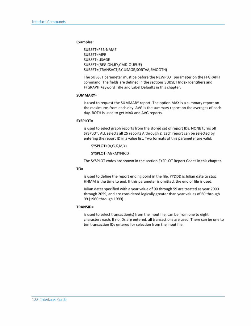
Interface Commands
122 Interfaces Guide
Examples:
SUBSET=PSB-NAME SUBSET=MPR SUBSET=USAGE SUBSET=(REGION,BY,CMD-QUEUE) SUBSET=(TRANSACT,BY,USAGE,SORT=A,SMOOTH)
The SUBSET parameter must be before the NEWPLOT parameter on the FFGRAPH command. The fields are defined in the sections SUBSET Index Identifiers and FFGRAPH Keyword Title and Label Defaults in this chapter.
SUMMARY=
is used to request the SUMMARY report. The option MAX is a summary report on the maximums from each day. AVG is the summary report on the averages of each day. BOTH is used to get MAX and AVG reports.
SYSPLOT=
is used to select graph reports from the stored set of report IDs. NONE turns off SYSPLOT, ALL selects all 25 reports A through Z. Each report can be selected by entering the report ID in a value list. Two formats of this parameter are valid:
SYSPLOT=(A,G,K,M,Y)
SYSPLOT=AGKMYFBCD
The SYSPLOT codes are shown in the section SYSPLOT Report Codes in this chapter.
TO=
is used to define the report ending point in the file. YYDDD is Julian date to stop. HHMM is the time to end. If this parameter is omitted, the end of file is used.
Julian dates specified with a year value of 00 through 59 are treated as year 2000 through 2059, and are considered logically greater than year values of 60 through 99 (1960 through 1999).
TRANSID=
is used to select transaction(s) from the input file, can be from one to eight characters each. If no IDs are entered, all transactions are used. There can be one to ten transaction IDs entered for selection from the input file.
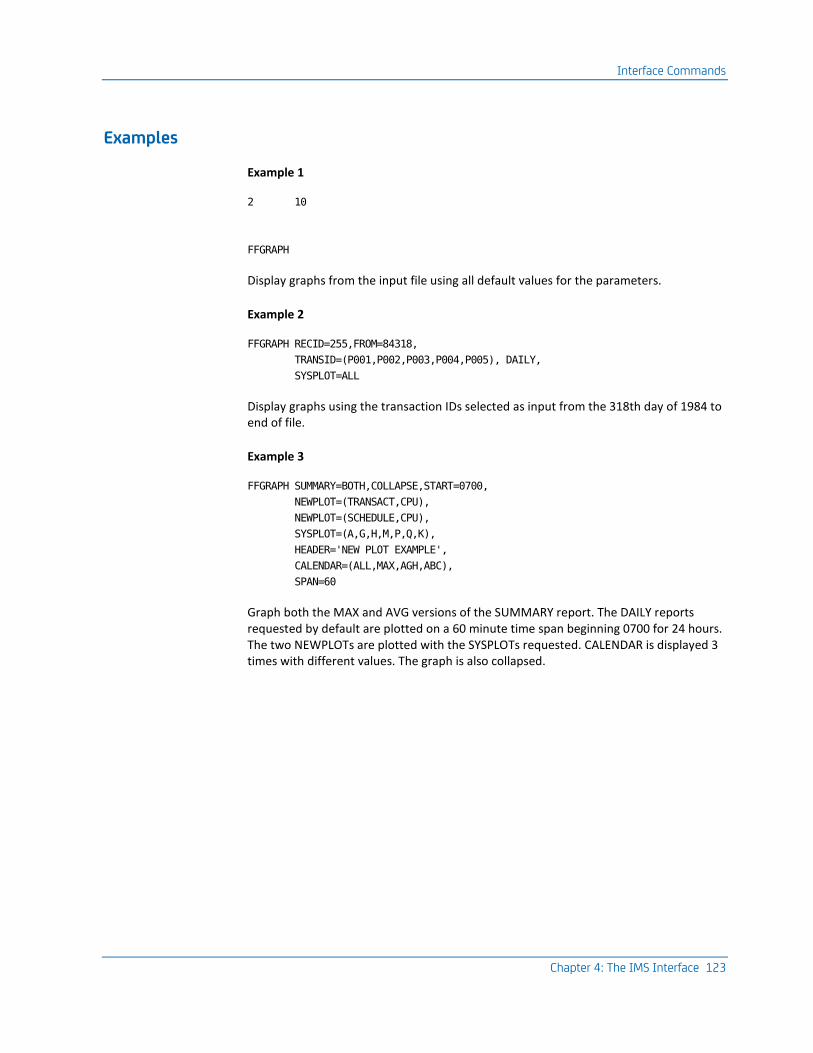
Interface Commands
Chapter 4: The IMS Interface 123
Examples
Example 1
2 10
FFGRAPH
Display graphs from the input file using all default values for the parameters.
Example 2
FFGRAPH RECID=255,FROM=84318,
TRANSID=(P001,P002,P003,P004,P005), DAILY,
SYSPLOT=ALL
Display graphs using the transaction IDs selected as input from the 318th day of 1984 to end of file.
Example 3
FFGRAPH SUMMARY=BOTH,COLLAPSE,START=0700,
NEWPLOT=(TRANSACT,CPU),
NEWPLOT=(SCHEDULE,CPU),
SYSPLOT=(A,G,H,M,P,Q,K),
HEADER='NEW PLOT EXAMPLE',
CALENDAR=(ALL,MAX,AGH,ABC),
SPAN=60
Graph both the MAX and AVG versions of the SUMMARY report. The DAILY reports requested by default are plotted on a 60 minute time span beginning 0700 for 24 hours. The two NEWPLOTs are plotted with the SYSPLOTs requested. CALENDAR is displayed 3 times with different values. The graph is also collapsed.

Interface Commands
124 Interfaces Guide
SYSPLOT Report Codes
Use this table to select predefined graph formats by specifying the associated report code as a value for the SYSPLOT parameter. For the definition of the field codes listed below, refer to the SELECT statement diagram in the Report Writer section of this chapter.
Report
Code Fields Plot
A A one up
B B one up
C C one up
D D one up
E E one up
F F one up
G G one up
H H one up
I I one up
J J one up
K A + B two up
L C + D two up
M E + F two up
N G + H two up
O I + J two up
P A + C two up
Q A + D two up
R A + E two up
S A + F two up
T A + G two up
U A + H two up

Interface Commands
Chapter 4: The IMS Interface 125
V B + C two up
W B + D two up
X B + E two up
Y B + F two up
Z B + G two up
2 B + H two up
3 C + E two up
4 C + F two up
5 C + G two up
6 C + H two up
7 D + E two up
8 D + F two up
9 D + G two up
0 D + H two up
$ E + G two up
* E + H two up
+ F + H two up
SUBSET Index Identifiers
The following items are values that may be specified for the index-name value in the SUBSET= parameter. These items determine the format and contents of the resources plotted for DAILY, SUMMARY and COMPOSITE graphs, and the type of data considered for the CALENDAR graph. Specify:
Index Name Values:
Name Description
TIME (default) time graph by time intervals
PSB-NAME 8 character index of PSB-NAME
TRANSACT 8 character transaction index
JOBNAME 8 character JOBNAME

Interface Commands
126 Interfaces Guide
Name Description
STEPNAME 8 character STEPNAME
REGION MPR--key - key is the protection key BPR--key - of that message region
MPR time graph of all message processing region
BPR time graph of all batch processing region
DLI time graph of DL/1 calls
FFGRAPH Keyword Title and Label Defaults
There are eight fields, designated Field A to Field H, that are available as reportable data elements for any Resource Utilization Graph execution. These fields can be selected in groups by specifying values for the FFGRAPH SUBSET= parameter. Valid values include:
Valid Values for the FFGRAPH SUBSET=parameter:
Value Reportable Group
TIME (default) Total system load, CPU, message and DL/I activity.
USAGE System load, CPU, message and DL/I activity by region type.
MSG-QUEUE or TEST-QUEUE
System load and message/test queueing activity.
CMD-QUEUE System load and CMD queueing activity.
UPDATE or EXCL System load and Update/Exclusive control queueing activity
DL/I DL/1 data call counts.
The following tables show which data elements can be graphed by selecting each field group. The order of fields is shown as A to H, corresponding to reportable field identifiers A to H as shown in the SYSPLOT Report Codes. Each reportable data element has an identifying keyword, default title, and label text.
Also shown are the origin of each field (from the data element names in the standard IBM IMS type X'07' log record dummy section) and the default maximum value against which the data element will be graphed.

Interface Commands
Chapter 4: The IMS Interface 127
Field Group Identifier: TIME:
Letter Keyword Fields Title/Label Maximum 100%
A TRANSACT DLRMCNT Transaction Utilization Report NBR of Transactions
OBS
B CPU DLRTIME Total CPU Utilization Report CPU Seconds
OBS
C ELAPSED Average ELAPSED Time
D SCHEDULE Record Count Total Number of Programs Scheduled NBR Scheduled
OBS
E DLI-TOTAL DLRCLCNT Total DL/I Calls Issued Report Call Count
OBS
F DLI-GETS DLRGU + DLRGN + DLRGHU + DLRGHNP + DLRGHN + DLRGNP
DL/I Get Call Issued Report Call Count
DLI-TOTAL
G DLI-ISRT DLRISRT Insert DL/I Calls Issued Report Call Count
DLI-TOTAL
H DLI-DLET DLRDLET Delete DL/I Calls Issued Report Call Count
DLI-TOTAL
I DLI-REPL DLRREPL Replace DL/I Calls Issued Report Call Count
DLI-TOTAL
J TOTLELAP Total Elapsed for Number of Transactions
Field Group Identifier: USAGE:
Letter Keyword Fields Title/Label Maximum 100%
A TRANSACT DLRMCNT Transaction Utilization Report Transaction Count
OBS
B CPU DLRTIME Total CPU Utilization CPU Seconds
OBS
C MPR-TRNS DLRMCNT for DLRTYPE=01
Message Region TRANS. Count Report Transaction Count
TRANSACT
D MPR-CPU DLR TIME for X'01' for DLRTYPE=01
Message Region CPU Report
CPU Seconds
CPU

Interface Commands
128 Interfaces Guide
Letter Keyword Fields Title/Label Maximum 100%
E MPR-DLI DLRCLCNT for X'01' for DLRTYPE=01
Message Region DL/I Call Count Report DL/I Call Count
OBS
F BPR-TRNS DLRMCNT for DLRTYPE=02
Batch Message Region TRANS. Count Report Transaction Count
TRANSACT
G BPR-CPU DLRTIME for X'02' for DLRTYPE=02
Batch Message Region CPU Report CPU Seconds
CPU
H BPR-DLI DLRCLCNT for
X'02' for
DLRTYPE=02
Batch Message Region DL/I Calls Report DL/I Calls Count
OBS
Field Group Identifier: MSG-QUEUE or TEST=QUEUE:
Letter Keyword Fields Title/Label Maximum 100%
A TRANSACT DLRMCNT Transaction Utilization Report Transaction Count
OBS
B MQ-GU DLRGUMES MSG Queue Get Unique Call Count Reports
NBR of GU Calls
OBS
C MQ-GN DLRGNMES MSG Queue Get Next Call Count Report NBR of GN Calls
OBS
D MQ-ISRT DLRISMES MSG Queue Insert Call Count Report NBR of ISRT Calls
OBS
E MQ-PURG DLRPUMES MSG Queue Purge Call Count Report NBR of PURG Calls
OBS
F TQ-ENQUE DLRTSTNQ Test Enqueue Report
Test Enqueues
OBS
G TQ-WAITS DLRTSTWT Number of Waits on Test Enqueue Test Waits
OBS
H TQ-DEQUE DLRTSTDQ Number of Test Dequeues Report Test Dequeues
OBS
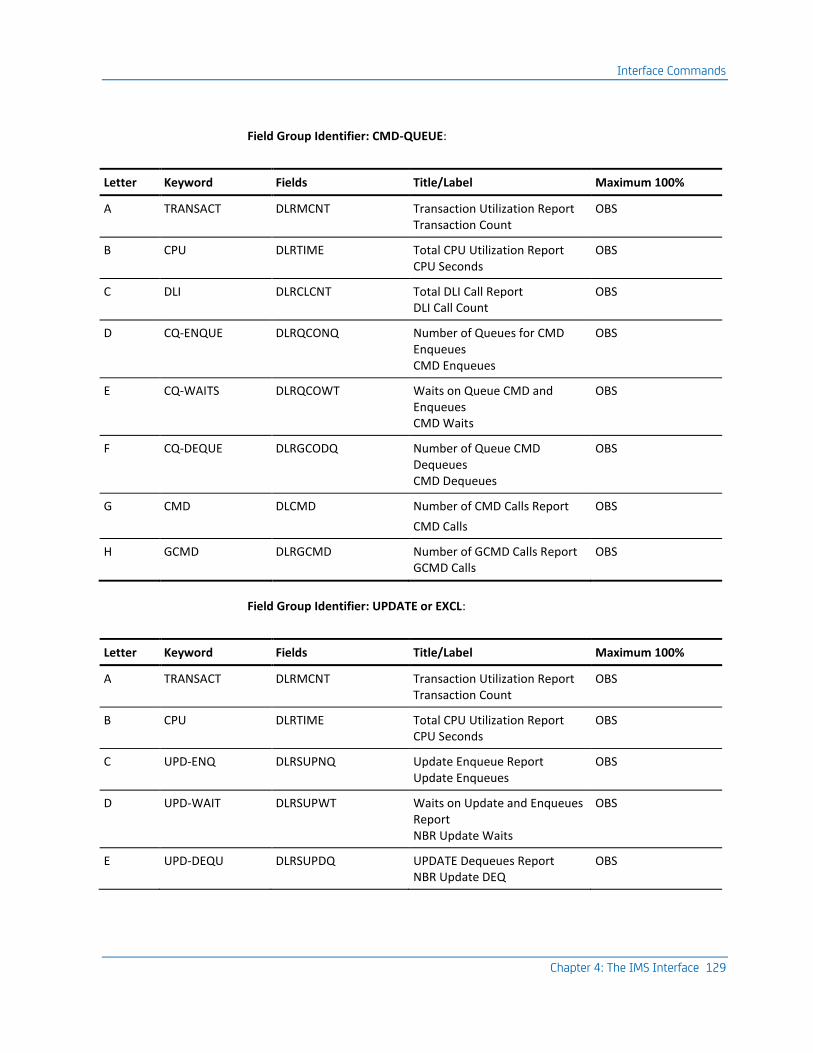
Interface Commands
Chapter 4: The IMS Interface 129
Field Group Identifier: CMD-QUEUE:
Letter Keyword Fields Title/Label Maximum 100%
A TRANSACT DLRMCNT Transaction Utilization Report Transaction Count
OBS
B CPU DLRTIME Total CPU Utilization Report CPU Seconds
OBS
C DLI DLRCLCNT Total DLI Call Report DLI Call Count
OBS
D CQ-ENQUE DLRQCONQ Number of Queues for CMD Enqueues CMD Enqueues
OBS
E CQ-WAITS DLRQCOWT Waits on Queue CMD and Enqueues CMD Waits
OBS
F CQ-DEQUE DLRGCODQ Number of Queue CMD Dequeues CMD Dequeues
OBS
G CMD DLCMD Number of CMD Calls Report
CMD Calls
OBS
H GCMD DLRGCMD Number of GCMD Calls Report GCMD Calls
OBS
Field Group Identifier: UPDATE or EXCL:
Letter Keyword Fields Title/Label Maximum 100%
A TRANSACT DLRMCNT Transaction Utilization Report Transaction Count
OBS
B CPU DLRTIME Total CPU Utilization Report CPU Seconds
OBS
C UPD-ENQ DLRSUPNQ Update Enqueue Report Update Enqueues
OBS
D UPD-WAIT DLRSUPWT Waits on Update and Enqueues Report NBR Update Waits
OBS
E UPD-DEQU DLRSUPDQ UPDATE Dequeues Report NBR Update DEQ
OBS

Interface Commands
130 Interfaces Guide
Letter Keyword Fields Title/Label Maximum 100%
F EXCL-ENQ DLREXCNQ Exclusive Enqueues Report NBR EXCL Waits
OBS
G EXCL-WTS DLREXCWT Waits on Exclusive Enqueues NBR EXCL Waits
OBS
H EXCL-DEQ DLREXCDQ Exclusive Dequeues Report NBR EXCL DEQ
OBS
KEYWORD Command
The KEYWORD command controls the description of each reportable data element. Use the KEYWORD command to change data element titles, labels, or units; to set maximum values for graph scale; and to select appropriate units.

Interface Commands
Chapter 4: The IMS Interface 131
The format for the KEYWORD command is as follows:
Keyword Command Format:
Command Operands
[LABEL] keyword
[,CHAR = {* } ]
[ {(char)} ]
[ {+.} ]
[ {-.} ]
[,COMPUTE= (KEY1, {/ } ,KEY2) ]
[ {* } ]
[,LABEL = '- 30 char -']
[ {999999999 } ]
[MAXval = {999999.999} ]
[ {'keyword' } ]
[ {TOTAL } ]
[ {V } ]
[ {V9 } ]
[ {V99 } ]
[ {V999 } ]
[,SCALE= {V9999 } ]
[ {percent/%} ]
[ {V9% } ]
[ {V99% } ]
[ {HHMMSS } ]
[,TITLE = '- 40 char -']
[,UNITS = {ONES } ]
[ {THOUSANDS} ]
[ {n } ]
[,100PCT= {MAX} ]
where:
KEYWORD command names are by default:
TRANSACT DLI-GETS CPU DLI-ISRT SCHEDULE DLI-DLET DLI-TOTAL DLI-REPL
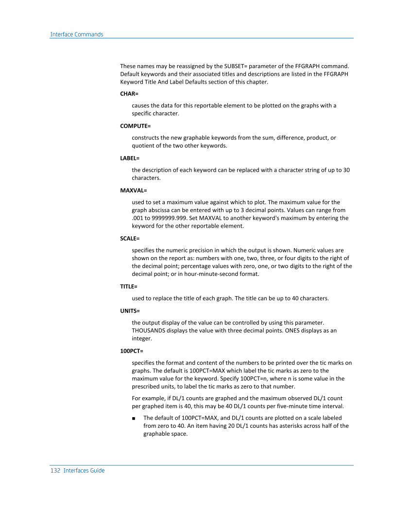
Interface Commands
132 Interfaces Guide
These names may be reassigned by the SUBSET= parameter of the FFGRAPH command. Default keywords and their associated titles and descriptions are listed in the FFGRAPH Keyword Title And Label Defaults section of this chapter.
CHAR=
causes the data for this reportable element to be plotted on the graphs with a specific character.
COMPUTE=
constructs the new graphable keywords from the sum, difference, product, or quotient of the two other keywords.
LABEL=
the description of each keyword can be replaced with a character string of up to 30 characters.
MAXVAL=
used to set a maximum value against which to plot. The maximum value for the graph abscissa can be entered with up to 3 decimal points. Values can range from .001 to 9999999.999. Set MAXVAL to another keyword's maximum by entering the keyword for the other reportable element.
SCALE=
specifies the numeric precision in which the output is shown. Numeric values are shown on the report as: numbers with one, two, three, or four digits to the right of the decimal point; percentage values with zero, one, or two digits to the right of the decimal point; or in hour-minute-second format.
TITLE=
used to replace the title of each graph. The title can be up to 40 characters.
UNITS=
the output display of the value can be controlled by using this parameter. THOUSANDS displays the value with three decimal points. ONES displays as an integer.
100PCT=
specifies the format and content of the numbers to be printed over the tic marks on graphs. The default is 100PCT=MAX which label the tic marks as zero to the maximum value for the keyword. Specify 100PCT=n, where n is some value in the prescribed units, to label the tic marks as zero to that number.
For example, if DL/1 counts are graphed and the maximum observed DL/1 count per graphed item is 40, this may be 40 DL/1 counts per five-minute time interval.
■ The default of 100PCT=MAX, and DL/1 counts are plotted on a scale labeled from zero to 40. An item having 20 DL/1 counts has asterisks across half of the graphable space.

Interface Commands
Chapter 4: The IMS Interface 133
■ Specify 100PCT=50, and DL/1 counts are plotted on a scale labeled from zero to 50. An item having 20 DL/1 counts has asterisks across two-fifths of the graphable space.
■ Specify 100PCT=100, and DL/1 counts are plotted on a scale labeled from zero to 100. An item having 20 DL/1 counts has asterisks across half of the graphable space.
KEYWORD Example
CPUR MAXVAL=25000,CHAR=*,
TITLE='REAL CPU',
LABEL='NUMBER OF SECONDS'
TRANSLATE Command
The TRANSLATE command controls the production of a translated output tape. It is also required if you wish to create EXTDATA. This translated output tape is used as input to the Report Writer. Use the TRANSLATE command to:
■ request the production of the translated output tape
■ identify the User Accounting Table, if any, that defines user accounting field contents in the translated records
■ specify a CPU identifier to be associated with the translated IMS data

Interface Commands
134 Interfaces Guide
The following is the format of the TRANSLATE command:
Command Operands
[LABEL] TRANSLATE
[SUFFIX [= {AT} ] ]
[ [ {xx} ] ]
[,CPUID= {I} ]
[ {x} ]
[,USEPSB= {YES} ]
[ { NO} ]
SUFFIX=
specifies the two-character suffix of the User Accounting Table load module name. The suffix is appended to the first six letters of the name JSIIMU to identify the load module name of the User Accounting Table.
For example, specifying SUFFIX=01 causes the interface to load a User Accounting Table named JSIIMU01. Specifying SUFFIX=AT would cause loading of module JSIIMUAT.
This parameter is optional. If SUFFIX= is not specified, no User Accounting Table is loaded and the user accounting fields in all translated records contain blanks.
CPUID=
specifies the one-character CPU identifier that is put into the IMS Interface interface summary records. This CPU identification can be used for various grouping and chargeback rate application functions by the Report Writer.
USEPSB=
specifies that if a Transaction ID is blank to move an asterisk followed by the first seven characters of the PSB name into the transaction ID. If NO is specified, the transaction is rejected.
Note: No parameter or keyword is required to create EXTDATA. All that is required is a CAIJSACT DD statement and a valid TRANSLATE command.

Interface Commands
Chapter 4: The IMS Interface 135
Sample Resource Utilization Graphs Examples
Example 1: Daily Run -- 30-Minute Interval:
CA RESOURCE UTILIZATION GRAPHS PAGE 1
CA JARS IMS INTERFACE 7.2 9811JR720 5 OCT 1998 11
TIME OF MEASUREMENT IS FROM 94/08/15 AT 04.21.40 DAILY 00.00.00 TO 00.00.00
TO 94/08/15 AT 14.01.20 INCLUDES 94/08/15
C P U U T I L I Z A T I O N
TIME TRANSACT CPU 0 10 20 30 40 50 60 70 80 90 100
HHMM COUNT SECONDS PCT +---------+--------+--------+--------+--------+--------+--------+--------+--------+--------+
0000-0400 ***** NO DATA *****
0400 11 2.432 0.1 *
0430-0600 ***** NO DATA *****
0600 3 0.217 0.0 *
0630 0 0.000 0.0 *
0700 0 0.000 0.0 *
0730 49 21.641 1.5 **
0800 116 67.499 4.9 *****
0830 359 91.005 6.6 *******
0900 741 101.251 7.3 ********
0930 660 130.172 9.4 **********
1000 563 239.093 17.3 ******************
1030 696 128.625 9.3 **********
1100 759 135.833 9.8 **********
1130 708 136.392 9.9 **********
1200 1000 81.310 5.9 ******
1230 863 101.471 7.3 ********
1300 347 42.569 3.0 ****
1330 364 94.400 6.8 *******
1400 3 0.865 0.0 *
1430-2400 ***** NO DATA *****
SUMMARY
MAX OBSERVED 239.093 17.3 ******************
AVG 452 85.923 6.2 *******
TOTAL 7242 1374.775 +---------+--------+--------+--------+--------+--------+--------+--------+--------+--------+
0 10 20 30 40 50 60 70 80 90 100
L E G E N D
KEYWORD MAXIMUM SCALE (100 PCT) PER 30 MINUTE INTERVAL DESCRIPTION
CPU 1374.775 SECONDS (TOTAL OF CPU ) CPU SECONDS
Commands
FFGRAPH SYSPLOT=B
CPU 100PCT=100
Description
CPU, a KEYWORD command, is used to plot the graph on a scale labeled zero to 100. The run date and time are displayed in the upper right corner of the report. The general header, Resource Utilization Graph, can be changed using the HEADER parameter in the FFGRAPH command.

Interface Commands
136 Interfaces Guide
The time of measurement shows the first and last date and time of the records being considered in this report. The graph type and the 24-hour period that is covered in this report both print under the run date. The title of the field being plotted can be changed with the TITLE parameter of the KEYWORD command.
This is a TIME graph, with 30 minute intervals, as shown in the leftmost column of the report. The second column is the count of transactions in each interval. The third column on this report is the cumulative value for CPU time found in each interval, because this is a CPU Utilization report. The next column, PCT, is the percentage of the maximum CPU time found for an interval (MAX OBSERVED) to the TOTAL of CPU (the 100% mark).
On a one-up graph, the tic marks of the graph expand across the page. The ***** NO DATA ***** line is displayed when more than 2 consecutive intervals contain no data, if the parameter COLLAPSE is ON.
The MAX OBSERVED FIELD shows the maximum CPU utilization found in the data. The average (AVG) across all intervals is also displayed. Totals are calculated for the fields displayed.
The legend describes the fields graphed above.
The maximum value used to scale the graph can be specified by using the MAXVAL parameter of the SET command (a KEYWORD command) or can be left to default to the highest value found in any interval (MAX OBSERVED). The interval being graphed can be set with the INTERVAL parameter.
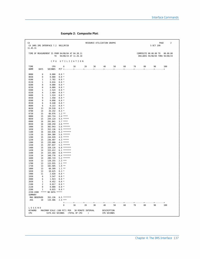
Interface Commands
Chapter 4: The IMS Interface 137
Example 2: Composite Plot:
CA RESOURCE UTILIZATION GRAPHS PAGE 2
CA JARS IMS INTERFACE 7.2 9811JR720 5 OCT 199
11.45.31
TIME OF MEASUREMENT IS FROM 94/08/04 AT 04.38.11 COMPOSITE 00.00.00 TO 00.00.00
TO 94/08/24 AT 11.26.10 INCLUDES 94/08/04 THRU 94/08/24
C P U U T I L I Z A T I O N
TIME CPU 0 10 20 30 40 50 60 70 80 90 100
HHMM DAYS SECONDS PCT +--------+--------+--------+--------+--------+--------+--------+--------+--------+--------+
0000 0 0.000 0.0 *
0030 0 0.000 0.0 *
0100 1 2.782 0.0 *
0130 1 0.016 0.0 *
0200 0 0.000 0.0 *
0230 0 0.000 0.0 *
0300 1 2.524 0.0 *
0330 4 2.484 0.0 *
0400 5 1.524 0.0 *
0430 9 1.458 0.0 *
0500 9 0.898 0.0 *
0530 6 0.448 0.0 *
0600 6 0.222 0.0 *
0630 13 29.528 0.5 *
0700 14 26.242 0.4 *
0730 15 66.976 1.2 **
0800 15 183.724 3.4 ****
0830 15 244.119 4.5 *****
0900 16 201.841 3.7 ****
0930 16 248.250 4.6 *****
1000 15 302.943 5.6 ******
1030 15 352.136 6.5 *******
1100 16 342.636 6.3 *******
1130 15 304.380 5.6 ******
1200 15 244.939 4.5 *****
1230 15 236.497 4.3 *****
1300 15 235.008 4.3 *****
1330 15 297.837 5.5 ******
1400 15 328.126 6.0 *******
1430 14 333.412 6.1 *******
1500 15 325.304 6.0 *******
1530 14 348.776 6.4 *******
1600 14 280.719 5.2 ******
1630 13 128.255 2.3 ***
1700 13 115.935 2.1 ***
1730 13 102.505 1.9 **
1800 13 60.399 1.1 **
1830 13 18.625 0.3 *
1900 11 2.020 0.0 *
1930 6 3.547 0.0 *
2000 6 1.923 0.0 *
2030 1 0.452 0.0 *
2100 2 0.017 0.0 *
2130 0 0.000 0.0 *
2200 1 0.015 0.0 *
2230-2400 ***** NO DATA *****
SUMMARY
MAX OBSERVED 352.136 6.5 *******
AVG 10 134.486 2.4 ***
+--------+--------+--------+--------+--------+--------+--------+--------+--------+--------+
0 10 20 30 40 50 60 70 80 90 100
L E G E N D
KEYWORD MAXIMUM SCALE (100 PCT) PER 30 MINUTE INTERVAL DESCRIPTION
CPU 5379.442 SECONDS (TOTAL OF CPU ) CPU SECONDS

Interface Commands
138 Interfaces Guide
Commands
FFGRAPH SYSPLOT=B,COMPOSITE=ON,DAILY=OFF
CPU 100PCT=100
Description
This is a COMPOSITE graph of the average activity across a number of days for each interval. Notice that the Time of Measurement shows which dates and times this report contains data for. The number of days displayed in the DAYS column indicates that data was found for the interval from that many days. The CPU SECONDS column is an average of all the days for that interval.
When more than two intervals have no data to report, all the consecutive intervals with no data is displayed as a single line if COLLAPSE is ON.
The legend is displayed at the end of every report.
Example 3: Average Summary Graph:
CA RESOURCE UTILIZATION GRAPHS PAGE 3
CA JARS IMS INTERFACE 7.2 9811JR720 5 OCT 1998 11
TIME OF MEASUREMENT IS FROM 94/08/04 AT 04.38.11 SUMMARY (AVG) 00.00.00 TO 00.00.00
TO 94/08/24 AT 11.26.10 INCLUDES 94/08/04 THRU 94/08/24
C P U U T I L I Z A T I O N T O T A L D L / I C A L L S
TRANSACT CPU 0 25 50 75 100 DLI$TOTL 0 25 50 75 100
DATE COUNT SECONDS PCT +---------+---------+---------+---------+ CALLS PCT +---------+---------+--------+-------+
10/02 2195 253.631 39.5 **************** 32691 17.0 *******
10/03 2134 215.011 33.5 ************** 32630 17.0 *******
10/04 2214 181.183 28.2 ************ 34917 18.2 ********
10/05 2202 211.854 33.0 ************** 41892 21.9 *********
10/08 3022 240.473 37.5 **************** 46291 24.2 **********
10/09 2522 183.872 28.6 ************ 36188 18.9 ********
10/10 2228 163.430 25.4 *********** 42562 22.2 *********
10/11 1973 161.193 25.1 *********** 32182 16.8 *******
10/12 1900 146.353 22.8 ********** 35886 18.7 ********
10/13 452 85.923 13.4 ****** 15295 7.9 ****
10/15 1817 162.957 25.4 *********** 37041 19.3 ********
10/16 1564 139.324 21.7 ********* 34746 18.1 ********
10/17 2079 209.346 32.6 ************** 58082 30.3 *************
10/18 1439 140.696 21.9 ********* 37841 19.7 ********
10/19 3461 278.042 43.3 ****************** 72223 37.7 ****************
10/21 24 2.966 0.4 * 5 0.0 *
10/22 1883 177.531 27.6 ************ 35406 18.5 ********
SUMMARY
MAX OBSERVED 278.042 43.3 ****************** 72223 37.7 ****************
AVG 1947 173.752 27.0 *********** 36816 19.2 ********
+---------+---------+---------+---------+ +---------+---------+--------+-------+
0 25 50 75 100 0 25 50 75 100
L E G E N D
KEYWORD MAXIMUM SCALE (100 PCT) PER 30 MINUTE INTERVAL DESCRIPTION
CPU 641.177 SECONDS (MAXIMUM OBSERVED) CPU SECONDS
DLI$TOTL 191242 CALLS (MAXIMUM OBSERVED) TOTAL DLI CALLS

Interface Commands
Chapter 4: The IMS Interface 139
Commands
FFGRAPH SYSPLOT=X,SUMMARY=AVG,DAILY=OFF
CPU 100PCT=100
DLI$TOTL 100PCT=100
Description
This summary graph is a plot of the average interval values calculated for each day with the maximum being of the greatest average interval value.
Example 4: Total Summary Graph:
CA RESOURCE UTILIZATION GRAPHS PAGE 4
CA JARS IMS INTERFACE 7.2 9811JR720 5 OCT 1998 11
TIME OF MEASUREMENT IS FROM 94/08/04 AT 04.38.11 SUMMARY (TOTAL) 00.00.00 TO 00.00.00
TO 94/08/24 AT 11.26.10 INCLUDES 94/08/04 THRU 94/08/24
C P U U T I L I Z A T I O N
TRANSACT CPU 0 10 20 30 40 50 60 70 80 90 100
DATE COUNT SECONDS PCT +---------+---------+---------+---------+---------+---------+---------+---------+--------+-------+
010/02 63681 7355.320 91.2 ********************************************************************************************
10/03 59752 6020.321 74.6 ***************************************************************************
10/04 64206 5254.332 65.1 ******************************************************************
10/05 59475 5720.061 70.9 ***********************************************************************
10/08 54397 4328.520 53.6 ******************************************************
10/09 73141 5332.308 66.1 *******************************************************************
10/10 66862 4902.928 60.8 *************************************************************
10/11 65113 5319.390 65.9 ******************************************************************
10/12 58906 4536.964 56.2 *********************************************************
10/13 7242 1374.775 17.0 ******************
10/15 54519 4888.738 60.6 *************************************************************
10/16 48502 4319.050 53.5 ******************************************************
10/17 58234 5861.707 72.6 *************************************************************************
10/18 46065 4502.300 55.8 ********************************************************
10/19 100372 8063.218 100.0 **************************************************************************************************
10/21 48 5.932 0.0 *
10/22 16947 1597.783 19.8 ********************
SUMMARY
MAX OBSERVED 8063.218 100.0 **************************************************************************************************
AVG 52791 4669.626 57.9 **********************************************************
+---------+---------+---------+---------+---------+---------+---------+--------+--------+--------+
0 10 20 30 40 50 60 70 80 90 100
L E G E N D
KEYWORD MAXIMUM SCALE (100 PCT) PER 1440 MINUTE INTERVAL DESCRIPTION
CPU 8063.218 SECONDS (MAXIMUM OBSERVED) CPU SECONDS

Interface Commands
140 Interfaces Guide
Commands
FFGRAPH SYSPLOT=B,SUMMARY=ON,SPAN=1440
CPU 100PCT=100
Description
This summary is the totals of the field from each day plotted against one another. The total is plotted by setting the INTERVAL=1440. Total of the field for each day is displayed in CPU SECONDS. The time interval is 1440 (for 24-hour period).
Example 5: Daily PSB Usage:
CA RESOURCE UTILIZATION GRAPHS PAGE 5
CA JARS IMS INTERFACE 7.2 9811JR720 5 OCT 1998 16
TIME OF MEASUREMENT IS FROM 94/08/04 AT 05.14.25 DAILY 00.00.00 TO 00.00.00
TO 94/08/04 AT 17.32.09 INCLUDES 94/08/04
T O T A L D L / I C A L L S
DLI$TOTL 0 9989 19978 29967 39956 49945 59934 69923 79912 89901 99890
PSB-NAME CALLS PCT +---------+---------+---------+---------+---------+---------+---------+---------+--------+--------+
AZ00T00 150 0.1 *
DFKE0000 146 0.1 *
PV00T00 6 0.0 *
RT00T00 1949 1.9 **
SAPB1CM 12047 12.0 *************
VI00T01 9371 9.3 **********
VI00T02 10975 10.9 ***********
VS00T00 25279 25.3 **************************
WH00T00 4360 4.3 *****
WH00T01 234 0.2 *
WH00T02 33804 33.8 **********************************
WH00T03 99890 100.0 ***************************************************************************************************
WH00T04 3783 3.7 ****
WH00T05 3553 3.5 ****
WH00T06 30 0.0 *
WH00T09 167 0.1 *
WM00T00 3163 3.1 ****
XT00T00 1156 1.1 **
SUMMARY
MAX OBSERVED 99890 100.0 ***************************************************************************************************
AVG 11670 11.6 ************
TOTAL 210063 +---------+---------+---------+---------+---------+---------+---------+---------+--------+--------+
0 9989 19978 29967 39956 49945 59934 69923 79912 89901 99890
L E G E N D
KEYWORD MAXIMUM SCALE (100 PCT) DESCRIPTION
DLI$TOTL 99890 CALLS (MAXIMUM OBSERVED) TOTAL DLI CALLS

Interface Commands
Chapter 4: The IMS Interface 141
Commands
FFGRAPH SUBSET=PSB-NAME,SYSPLOT=E
Description
This is a daily graph of the file activity for a day. The PSB names sort alphabetically, but can be sorted by other fields with use of SORT value of the SUBSET parameter. The total activity for that field for the day is displayed in the DLI$TOTL CALLS column.
The legend describes the field. No time interval is considered because this is a file graph, not a time-related graph.
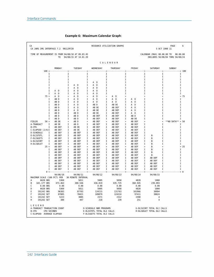
Interface Commands
142 Interfaces Guide
Example 6: Maximum Calendar Graph:
CA RESOURCE UTILIZATION GRAPHS PAGE 6
CA JARS IMS INTERFACE 7.2 9811JR720 5 OCT 1998 11
TIME OF MEASUREMENT IS FROM 94/08/10 AT 09.03.45 CALENDAR (MAX) 00.00.00 TO 00.00.00
TO 94/08/15 AT 14.01.20 INCLUDES 94/08/04 THRU 94/08/24
C A L E N D A R
MONDAY TUESDAY WEDNESDAY THURSDAY FRIDAY SATURDAY SUNDAY
100 +---------------+---------------+---------------+---------------+---------------+--------------+--------------+ 100
I I I I I I I I
I I I I I I I I
I I I I I I I I
I I I A D I I I I I
I I A D I A D I I I I I
I I A D I A D I I I I I
I A D I A D I A D I I I I I
I A D I A D I A D I I I I I
75 + A D + A D + A D + A D + + + + 75
I AB D I A D I A D I A D I A D I I I
I AB D I A D I A D I A D I A D I I I
I AB D I A D I AB D I AB DE I A D I I I
I AB D I A D I AB DE I AB DEF I A D I I I
I AB D I A D I AB DE I AB DEF I A D I I I
I AB D I AB D I AB DE I AB DEF I A D I I I
I AB D I AB D I AB DEF I AB DEF I AB D I I I
I AB D I AB D I AB DEF I AB DEF I AB DE I I I
FIELDS 50 + AB DE + AB D + AB DEF + AB DEF + AB DEF + + **NO DATA** + 50
A-TRANSACT I AB DE I AB D I AB DEF I AB DEF I AB DEF I I I
B-CPU I AB DEF I AB DE I AB DEF I AB DEF I AB DEF I I I
C-ELAPSED (J/A)I AB DEF I AB DE I AB DEF I AB DEF I AB DEF I I I
D-SCHEDULE I AB DEF I AB DEF I AB DEF I AB DEF I AB DEF I I I
E-DLI$TOTL I AB DEF I AB DEF I AB DEF I AB DEF I AB DEF I B I I
F-DLI$GETS I AB DEF I AB DEF I AB DEF I AB DEF I AB DEF I B I I
G-DLI$ISRT I AB DEF I AB DEF I AB DEF I AB DEF I AB DEF I B I I
H-DLI$DLET I AB DEF I AB DEF I AB DEF I AB DEF I AB DEF I B I I
25 + AB DEF + AB DEF + AB DEF + AB DEF + AB DEF + B + + 25
I AB DEF I AB DEF I AB DEF I AB DEF I AB DEF I B I I
I AB DEF I AB DEF I AB DEF I AB DEF I AB DEF I B I I
I AB DEF I AB DEF I AB DEF I AB DEF I AB DEF I B I I
I AB DEF I AB DEF I AB DEF I AB DEF I AB DEF I AB DEF I I
I AB DEF I AB DEF I AB DEF I AB DEF I AB DEF I AB DEF I I
I AB DEF I AB DEF I AB DEF I AB DEF I AB DEF I AB DEF I I
I AB DEF I AB DEF I AB DEF I AB DEF I AB DEF I AB DEF I I
I AB DEF I AB DEF I AB DEF I AB DEF I AB DEF I AB DEF I I
0 +---------------+---------------+---------------+---------------+---------------+--------------+--------------+ 0
94/08/10 94/08/11 94/08/12 94/08/13 94/08/14 94/08/15
MAXIMUM SCALE (100 PCT) PER 30 MINUTE INTERVAL
A 6628 OBS 5369 5811 5905 5058 4828 1000
B 641.177 OBS 473.463 380.546 436.819 435.725 368.945 239.093
C 0.00 OBS 0.00 0.00 0.00 0.00 0.00 0.00
D 6628 OBS 5369 5811 5905 5058 4828 1000
E 191242 OBS 96383 87703 124215 131763 101966 30994
F 191242 SET 87805 78421 109879 124224 97411 30624
G 191242 SET 5223 3885 2371 2312 2390 4
H 191242 SET 380 447 218 239 251 4
L E G E N D
A-TRANSACT TRANSACTION COUNT D-SCHEDULE NBR PROGRAMS G-DLI$ISRT TOTAL DLI CALLS
B-CPU CPU SECONDS E-DLI$TOTL TOTAL DLI CALLS H-DLI$DLET TOTAL DLI CALLS
C-ELAPSED AVERAGE ELAPSED F-DLI$GETS TOTAL DLI CALLS

Interface Commands
Chapter 4: The IMS Interface 143
Commands
FFGRAPH CALENDAR=MAX,DAILY=OFF
Description
Maximum calendar graphs take the maximum values of fields, and plots them in relation to each other for each day of a week. The date and time of first and last record used as input to find the maximum scale is displayed as Time of Measurement. A list of fields being plotted is displayed to the left of the graph. This list is controlled by the CALENDAR parameter. The maximum scale is set (SET) or observed (OBS) based on input control statements. The time interval is used to calculate the field values.
The legend displays the labels and values of each field graphed.
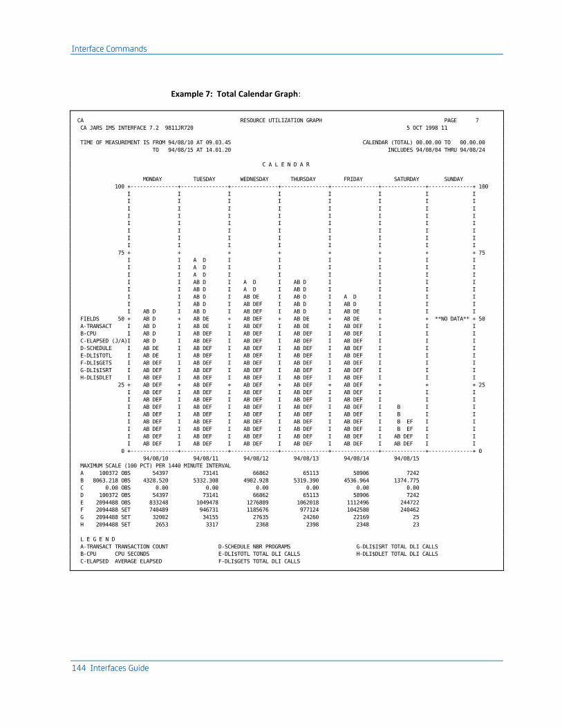
Interface Commands
144 Interfaces Guide
Example 7: Total Calendar Graph:
CA RESOURCE UTILIZATION GRAPH PAGE 7
CA JARS IMS INTERFACE 7.2 9811JR720 5 OCT 1998 11
TIME OF MEASUREMENT IS FROM 94/08/10 AT 09.03.45 CALENDAR (TOTAL) 00.00.00 TO 00.00.00
TO 94/08/15 AT 14.01.20 INCLUDES 94/08/04 THRU 94/08/24
C A L E N D A R
MONDAY TUESDAY WEDNESDAY THURSDAY FRIDAY SATURDAY SUNDAY
100 +---------------+---------------+---------------+---------------+---------------+--------------+--------------+ 100
I I I I I I I I
I I I I I I I I
I I I I I I I I
I I I I I I I I
I I I I I I I I
I I I I I I I I
I I I I I I I I
I I I I I I I I
75 + + + + + + + + 75
I I A D I I I I I I
I I A D I I I I I I
I I A D I I I I I I
I I AB D I A D I AB D I I I I
I I AB D I A D I AB D I I I I
I I AB D I AB DE I AB D I A D I I I
I I AB D I AB DEF I AB D I AB D I I I
I AB D I AB D I AB DEF I AB D I AB DE I I I
FIELDS 50 + AB D + AB DE + AB DEF + AB DE + AB DE + + **NO DATA** + 50
A-TRANSACT I AB D I AB DE I AB DEF I AB DE I AB DEF I I I
B-CPU I AB D I AB DEF I AB DEF I AB DEF I AB DEF I I I
C-ELAPSED (J/A)I AB D I AB DEF I AB DEF I AB DEF I AB DEF I I I
D-SCHEDULE I AB DE I AB DEF I AB DEF I AB DEF I AB DEF I I I
E-DLI$TOTL I AB DE I AB DEF I AB DEF I AB DEF I AB DEF I I I
F-DLI$GETS I AB DEF I AB DEF I AB DEF I AB DEF I AB DEF I I I
G-DLI$ISRT I AB DEF I AB DEF I AB DEF I AB DEF I AB DEF I I I
H-DLI$DLET I AB DEF I AB DEF I AB DEF I AB DEF I AB DEF I I I
25 + AB DEF + AB DEF + AB DEF + AB DEF + AB DEF + + + 25
I AB DEF I AB DEF I AB DEF I AB DEF I AB DEF I I I
I AB DEF I AB DEF I AB DEF I AB DEF I AB DEF I I I
I AB DEF I AB DEF I AB DEF I AB DEF I AB DEF I B I I
I AB DEF I AB DEF I AB DEF I AB DEF I AB DEF I B I I
I AB DEF I AB DEF I AB DEF I AB DEF I AB DEF I B EF I I
I AB DEF I AB DEF I AB DEF I AB DEF I AB DEF I B EF I I
I AB DEF I AB DEF I AB DEF I AB DEF I AB DEF I AB DEF I I
I AB DEF I AB DEF I AB DEF I AB DEF I AB DEF I AB DEF I I
0 +---------------+---------------+---------------+---------------+---------------+--------------+--------------+ 0
94/08/10 94/08/11 94/08/12 94/08/13 94/08/14 94/08/15
MAXIMUM SCALE (100 PCT) PER 1440 MINUTE INTERVAL
A 100372 OBS 54397 73141 66862 65113 58906 7242
B 8063.218 OBS 4328.520 5332.308 4902.928 5319.390 4536.964 1374.775
C 0.00 OBS 0.00 0.00 0.00 0.00 0.00 0.00
D 100372 OBS 54397 73141 66862 65113 58906 7242
E 2094488 OBS 833248 1049478 1276889 1062018 1112496 244722
F 2094488 SET 740489 946731 1185676 977124 1042580 240462
G 2094488 SET 32002 34155 27635 24260 22169 25
H 2094488 SET 2653 3317 2368 2398 2348 23
L E G E N D
A-TRANSACT TRANSACTION COUNT D-SCHEDULE NBR PROGRAMS G-DLI$ISRT TOTAL DLI CALLS
B-CPU CPU SECONDS E-DLI$TOTL TOTAL DLI CALLS H-DLI$DLET TOTAL DLI CALLS
C-ELAPSED AVERAGE ELAPSED F-DLI$GETS TOTAL DLI CALLS

Interface Commands
Chapter 4: The IMS Interface 145
Commands
FFGRAPH CALENDAR=ON,SPAN=1440
Description
This graph is a plot of the total values against one another. The interval is set to 1440 so the fields are cumulative daily totals. The values below the maximum scale are totals for the days. The maximum is now the largest total of the period considered.

The Wizard Report Writer
146 Interfaces Guide
The Wizard Report Writer
Output
The output report formats vary from user to user depending on the report control statements used. Additional output in the form of a historical database on magnetic tape is discussed in the CA JARS User Guide
The Wizard Report Writer error messages and other diagnostics are in the CA JARS Message Guide.
All user-defined reports formatted by the Wizard Report Writer are in three parts:
1. Header information
2. Detail information
3. Summary information
A --> CA - DAILY IMS COST REVIEW
E --> OPERATING COST $1,000
BEGIN DATE - 09/22/94 <--C F --> RUN DATE - 09/
END DATE - 09/22/94 <--D G --> PAG
JOB PSB TX STOP TX STOP PERCENT TOTAL DISTRIBUTED
DESCRIPTION <--B CONTROL NAME NAME DATE TIME TOTAL CHARGE CHARGE
CA <-H 85
I -> PRODUCTION WORK 8502
J --> T SMITH 8502614B
MSGREG1 PSBPERS 94/09/22 01.09.37 4.633 $22.15 $47
MSGREG1 PSBPERS 94/09/22 01.19.27 4.633 $22.15 $47
MSGREG1 PSBPERS 94/09/22 01.28.02 4.037 $19.30 $40
MSGREG1 PSBACCT 94/09/22 01.34.12 8.093 $38.69 $81
T SMITH 8502614B 21.396 $102.29 $215
H JONES 8502633B
MSGREG2 PSBACCT 94/09/22 02.54.49 34.669 $170.89 $347
MSGREG2 PSBPAYR 94/09/22 02.54.49 11.539 $55.17 $115
MSGREG1 PSBACCT 94/09/22 02.56.07 10.985 $52.52 $110
MSGREG1 PSBACCT 94/09/22 02.57.20 12.182 $58.24 $122
H JONES 8502633B 34.706 $165.93 $347
PRODUCTION WORK 8502 56.101 $268.52 $561
PROGRAMMER TEST 8524
L BROWN 8524999
K --> RBXTEST PSBTEST1 94/09/22 18.25.55 12.464 $59.59 $125
RBXTEST PSBTEST1 94/09/22 18.25.55 4.005 $19.15 $40
RBXTEST PSBTEST7 94/09/22 18.26.19 3.683 $17.61 $37
RBXTEST PSBTEST3 94/09/22 18.26.44 4.775 $22.83 $48
RBXTEST PSBTEST1 94/09/22 18.30.56 31.369 $149.97 $313
RBXTEST PSBTEST3 94/09/22 18.30.56 10.435 $49.89 $104
RBXTEST PSBTEST1 94/09/22 18.32.02 20.933 $100.08 $209
L BROWN 8524999 44.455 $209.56 <-M-> $438
PROGRAMMER TEST 8524 44.455 $209.56 <-N-> $438
CA 85 100.556 $478.08 <-P-> $1,000
100.556 $478.08 <-R-> $1,000
Note: This report is described in detail on the next two pages.

The Wizard Report Writer
Chapter 4: The IMS Interface 147
Header Information
The report header is eight lines of information in a standard format for all reports. Item A is introduced using the HEADER statement. See the HEADER Statement section in this chapter. Items C, D, E, and F are introduced using the SELECT Statement.
The left-hand items, C and D, start in the first print position. The righthand items, E, F, and G, adjust automatically to the computed print line length. The line length is based on the field length of the selected data elements and the number of blanks preceding each element as requested by you using the DISPLAY statement. See the DISPLAY Statement section in this chapter. Item B is determined by the DISPLAY statement; individual titles can be modified via the TITLE statement. See the TITLE Statement section in this chapter.
Header Line 1
The top-of-page header line displays the report title for a given report as indicated by A. The starting print position for the report title is defined by you on the HEADER statement.
Header Line 2
The operating cost is retrieved from the PARMS statement. If this value is not present or not relevant to a given report, item E is omitted.
Header Line 3
The third line displays the report begin date and run date, items C and F, respectively.
Header Line 4
The fourth line displays the report end date and the report page number, items D and G, respectively. The page number is a four-digit, zero-suppressed value.
Header Lines 5 and 6
These lines are intentionally blank on every report.
Header Lines 7 and 8
These lines display the titles of the selected output data elements at the print positions defined by you on the DISPLAY statement. The titles do not exceed the individual field lengths as indicated in the IMS Interface Output Data Elements Table later in this chapter.
Detail Information
The detail line information may be optionally displayed for each record at the transaction level, item K.
You may elect to display the selected output data elements for each transaction on a given report. The transaction information is a summary of pertinent data for all the programs within that transaction.

Executing the Wizard Report Writer
148 Interfaces Guide
Summary Information
The summary line information is displayed for each change of data in a user-defined sort control field at any of the five sort levels. You may elect to display the selected output data elements at each of the five levels.
The forms are positioned to the top of the next page after printing the major summary line. This page eject occurs when the summary line option on the SORT statement is an E. By specifying a P, you can request a page eject after printing the major summary line with the page number reset to one.
Associated with each summarization level are description and control fields. You may elect to display these fields and associate personalized descriptive header information with the summary lines. This is accomplished through the use of DESCRIPT statements. See the DESCRIPT Statement section in this chapter.
In addition, the control field and summarization description can be displayed as headers to signal the beginning of a new summarization level as illustrated by items H, I and J. No other information appears on this line. Note that the descriptions have been staggered to present a more meaningful relationship between the different summarization levels. This is accomplished by appropriately spacing the summarization description in the field when preparing the DESCRIPT statements.
An additional final summary line, item R, is automatically displayed at the end of each report. All requested information that may logically be accumulated is presented as a final total on this line.
Executing the Wizard Report Writer
The Wizard Report Writer is executed as a standard batch job using basic IBM 370 facilities.
Data Set Use
The Wizard Report Writer requires several interrelated files to execute. The following list describes these data sets and their functions.
DDName File Name
Description Of Use
Predefined DCB Attributes
CAIJSHST Used to input IMS data produced by the Translate Utility.
RECFM, LRECL, and BLKSIZE set automatically

Executing the Wizard Report Writer
Chapter 4: The IMS Interface 149
DDName File Name
Description Of Use
Predefined DCB Attributes
anyname Output data set for summary file generated using the Summarization Feature.
RECFM, LRECL, and BLKSIZE set automatically
CAIJSACT Optional output DD for EXTDATA (only). Data will be written if the DD exists in your JCL and there is a valid TRANSLATE command.
RECFM, LRECL, and BLKSIZE set automatically
SORTWKnn Temporary data sets used as sort work area in sort phases.
RECFM, LRECL, and BLKSIZE set automatically
CAIJSCT1 Temporary data set to hold edited report control statements.
RECFM, LRECL, and BLKSIZE set automatically
CAIJSCT2 Same as CAIJSCT1 RECFM, LRECL, and BLKSIZE set automatically
CAIJSCIN Used to input report control statements
RECFM=F, LRECL=80
CAIJSPRT SYSOUT data set for output reports.
RECFM=F, LRECL=133
In addition to these data sets, the following files are required:
//STEPLIB DD DSN=____,DISP=SHR,UNIT=____,VOL=SER=_____
//SORTLIB DD DSN=SYS1.SORTLIB,DISP=SHR
//SYSOUT DD SYSOUT=____
//SNAPDUMP DD SYSOUT=____
The STEPLIB statement points to the DASD volume on which a partitioned data set (user library) resides that includes the Wizard Report Writer as a member. If the library has been cataloged on the system, then the unit parameter and volume identification are not necessary.
The SORTLIB statement is required during the sorting operations activated by the Wizard Report Writer. This data set contains modules which are essential to the execution of the program.
The SYSOUT statement provides an output data set for the messages displayed on the printer by the IBM or vendor-supplied sort/merge program. You should be aware that this ddname may vary from one installation to another depending on the options specified at the time the sort/merge program was installed. Typical substitute ddnames employed by users are SORTMSG, SYSPRINT, and so forth.
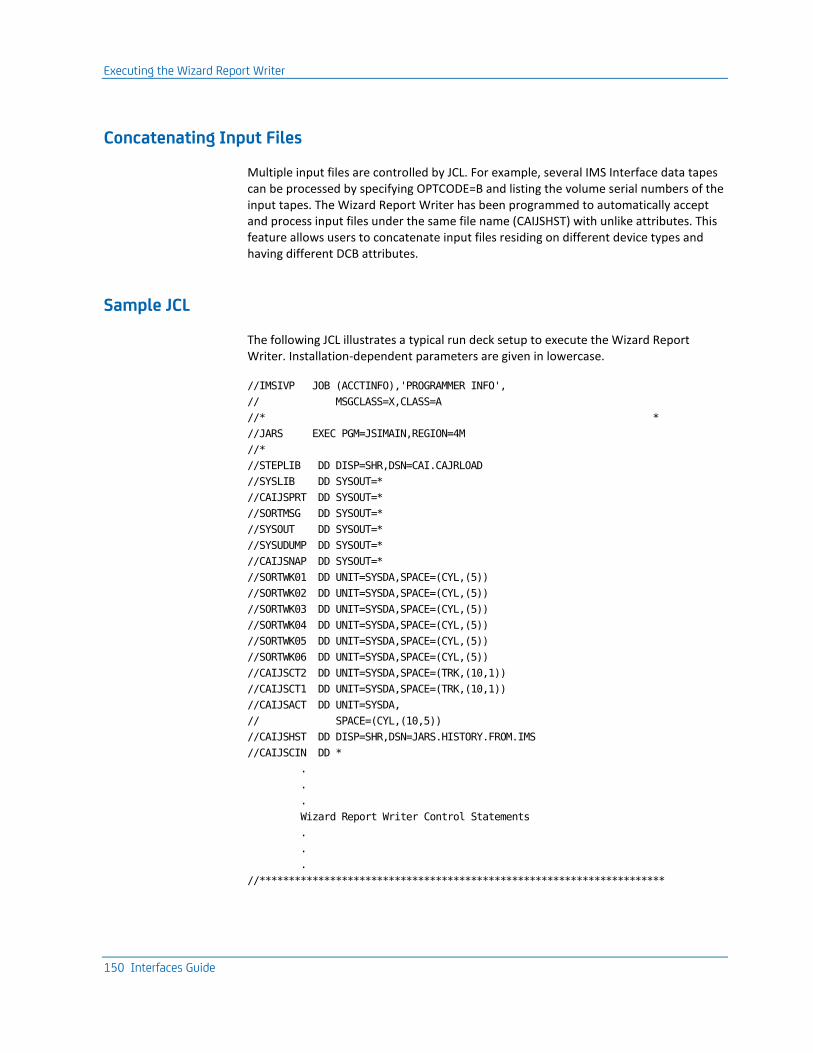
Executing the Wizard Report Writer
150 Interfaces Guide
Concatenating Input Files
Multiple input files are controlled by JCL. For example, several IMS Interface data tapes can be processed by specifying OPTCODE=B and listing the volume serial numbers of the input tapes. The Wizard Report Writer has been programmed to automatically accept and process input files under the same file name (CAIJSHST) with unlike attributes. This feature allows users to concatenate input files residing on different device types and having different DCB attributes.
Sample JCL
The following JCL illustrates a typical run deck setup to execute the Wizard Report Writer. Installation-dependent parameters are given in lowercase.
//IMSIVP JOB (ACCTINFO),'PROGRAMMER INFO',
// MSGCLASS=X,CLASS=A
//* *
//JARS EXEC PGM=JSIMAIN,REGION=4M
//*
//STEPLIB DD DISP=SHR,DSN=CAI.CAJRLOAD
//SYSLIB DD SYSOUT=*
//CAIJSPRT DD SYSOUT=*
//SORTMSG DD SYSOUT=*
//SYSOUT DD SYSOUT=*
//SYSUDUMP DD SYSOUT=*
//CAIJSNAP DD SYSOUT=*
//SORTWK01 DD UNIT=SYSDA,SPACE=(CYL,(5))
//SORTWK02 DD UNIT=SYSDA,SPACE=(CYL,(5))
//SORTWK03 DD UNIT=SYSDA,SPACE=(CYL,(5))
//SORTWK04 DD UNIT=SYSDA,SPACE=(CYL,(5))
//SORTWK05 DD UNIT=SYSDA,SPACE=(CYL,(5))
//SORTWK06 DD UNIT=SYSDA,SPACE=(CYL,(5))
//CAIJSCT2 DD UNIT=SYSDA,SPACE=(TRK,(10,1))
//CAIJSCT1 DD UNIT=SYSDA,SPACE=(TRK,(10,1))
//CAIJSACT DD UNIT=SYSDA,
// SPACE=(CYL,(10,5))
//CAIJSHST DD DISP=SHR,DSN=JARS.HISTORY.FROM.IMS
//CAIJSCIN DD *
.
.
.
Wizard Report Writer Control Statements
.
.
.
//*********************************************************************

Executing the Wizard Report Writer
Chapter 4: The IMS Interface 151
Control Statements
Formatting customized reports begins with the preparation of control statements. Each statement is identified by an eight-character alphanumeric statement type. The Wizard Report Writer checks each statement for syntax and other discrepancies which would cause problems in execution. All errors are flagged, and messages are printed identifying the problem areas.
The following control statements control the general aspects of the Wizard Report Writer execution:
■ SELECT (required)
■ CRITERIA (optional)
■ PARMS (optional)
Up to 15 reports can be produced in a single execution of the Wizard Report Writer. Each report is defined by a combination of the following control statements:
■ HEADER (required)
■ SORT (required)
■ DISPLAY (required)
■ GROUP (optional, for grouping feature)
■ GROUPC
■ RATE
■ CREDIT (optional, for chargeback and budget control)
■ DEBIT
■ BUDGET
■ TITLE
■ DESCRIPT
■ EXITS (see the CA JARS User Guide)
A unique set code identifies the report control statements for each report. This code is the first character in each statement; all the statements in the set contain the same set code. The Wizard Report Writer automatically orders and edits the report control statements prior to their use.
Note: The following sections describe the preparation of the Wizard Report Writer control statements. For each statement, there is a general description. Be sure to refer to both the general and the specific description when necessary.

Executing the Wizard Report Writer
152 Interfaces Guide
The transaction data processed by the Wizard Report Writer originates in the IMS system log data set. This log data set is processed by the IMS Interface. Using the TRANSLATE command, the interface can translate log data to input format for the Wizard Report Writer. It also uses a user-defined accounting table to assign cost center identification to the reformatted interface records.
These reformatted interface records are output by the interface into a file called the IMS Interface summary file.
BUDGET Statement
The BUDGET statement, identified by the statement type BUDGET, is optional. It provides a mechanism by which you may introduce budget figures to the Wizard Report Writer and compare them to actual costs for a given period of time. Budget figures may be associated with a specific transaction or with any summarization level (such as account, department, project).
Each BUDGET statement introduced to the Wizard Report Writer is formatted into an accounting record to be sorted and reported on as any other input. All BUDGET statement fields are formatted to corresponding fields according to the Basic Accounting Table. For processing purposes, the record is treated as a transaction.
The date and time fields are processed the same way as those on the CREDIT and DEBIT statements.
The budget amount field, in whole dollars, is carried through by the Wizard Report Writer and made available for display via the Output Data Elements Table. The difference between the budget amount and the total charge can be displayed at any level, as can the over-under budget figure. The percent budget spent can show what percentage of the budget amount has been spent at any display level.
Statement Position
Field Length
Field Name Notes
1 1 Set Code
2-9 8 Statement Type BUDGET
10 1 CPU Identification
19-34 16 User Information
35-40 6 Date YYMMDD
41-48 8 Job Name
49-54 6 Time HHMMSS
75-80 6 Budget Amount 999999V; dollars

Executing the Wizard Report Writer
Chapter 4: The IMS Interface 153
CREDIT Statement
This statement, identified by the statement type CREDIT, is optional. It is used to supplement the accounting algorithms defined on the RATE statements. Credits may be introduced to the Wizard Report Writer to be applied to a specific transaction or summarization level (account, department, project, etc.). Some typical uses for the CREDIT statement are to:
■ negate transaction abend costs
■ adjust prior months billing
■ provide volume processing discounts
Each CREDIT statement introduced to the Wizard Report Writer is formatted into an accounting record to be sorted and reported on as any other input. All CREDIT statement fields are formatted to corresponding fields according to the Basic Accounting Table. For processing purposes, the record is treated as a transaction.
The following fields, if not present on the CREDIT statement, are filled with blanks in the formatted record:
■ CPU identification
■ user information
■ transaction ID
The following fields, or any portion thereof, not present on the CREDIT statement are filled with high values (hex 'FF') in the formatted record:
■ date
■ time
For sorting purposes, it should be noted that the date field is moved to the transaction stop date and date record written fields. Also, the time field is moved to the transaction stop time and time record written fields in the formatted record as defined in the Basic Accounting Table. High values in any of these fields do not print when selected for display, and, therefore, can be used to cause credits to appear last in any group of records.
The credit amount field, in dollars and cents, is carried through by the Wizard Report Writer and made available for display in the Output Data Elements Table. The credit amount also affects (reduces) the total charge, distributed charge, and percent totals at any level of display.
Statement Position
Field Length
Field Name Notes
1 1 Set Code

Executing the Wizard Report Writer
154 Interfaces Guide
Statement Position
Field Length
Field Name Notes
2-9 8 Statement Type CREDIT
10 1 CPU Identification
19-34 16 User information
35-40 6 Date YYMDD
41-48 8 Job Name
49-54 6 Time HHMMSS
75-80 6 Credit Amount 9999V99; dollars
CRITERIA Statement
This statement, identified by the statement type CRITERIA, is optional. It provides a mechanism for selecting or rejecting input by date for processing by the Wizard Report Writer. You can establish a selection/rejection date range as follows:
DATE i ffffffff ssssssss
DATE
is the required keyword.
i
is the select (I = ) or reject (I = 1) indicator.
ffffffff
is the first date, the range beginning.
ssssssss
is the second date. If the second date is omitted, it defaults to the first date, in effect selecting or rejecting a single date.
If the CRITERIA statement is omitted, all input is processed. An extension to the record selection/rejection capability at the report level is available through the use of the grouping feature. This function is controlled by the GROUP and GROUPC statements which are discussed in detail later in this chapter.
Statement Position
Field Length
Field Name Notes
1 1 Reserved Must be blank
2-9 8 Statement Type CRITERIA

Executing the Wizard Report Writer
Chapter 4: The IMS Interface 155
Statement Position
Field Length
Field Name Notes
10-13 4 Keyword DATE
14 1 Select/Reject Indicator 1 = reject = select
15-22 8 First Date Range beginning date*
23-30 8 Second Date Range ending date* (optional if same as range beginning date)
* Dates must be entered in the format MM/DD/YY
Dates specified with a year value of 00 through 59 are treated as year 2000 through 2059, and are considered logically greater than year values of 60 through 99 (1960 through 1999).
DEBIT Statement
The DEBIT statement, identified by the statement type DEBIT, is optional. It is used in a similar manner as the CREDIT statement to supplement the accounting algorithms defined on the RATE statements. Debits may be introduced to the Wizard Report Writer to be applied to a specific transaction or summarization level (such as account, department, project). Some typical uses for the DEBIT statement are to:
■ charge for dedicated online devices
■ introduce disk space rental costs
■ bill specific accounts for other EDP functions used
The DEBIT statement format and processing is identical to that of the CREDIT statement described earlier. The only difference is in the use of the amount field, which has the effect of increasing the charges.
Statement Position
Field Length
Field Name Notes
1 1 Set Code
2-9 8 Statement Type DEBIT
10 1 CPU Identification
19-34 16 User Information
35-40 6 Date YYMMDD
41-48 8 Job Name
49-54 6 Time HHMMSS

Executing the Wizard Report Writer
156 Interfaces Guide
Statement Position
Field Length
Field Name Notes
75-80 6 Debit Amount 9999V99; dollars
DESCRIPT Statement
The DESCRIPT statement, identified by the statement type DESCRIPT, is optional. When the data element description field is selected, it can provide a description of the control field break at the header and summary line. See the data element ID 02 in the IMS Interface Output Data Elements Table later in this chapter.
The summarization level defines which sort control break the DESCRIPT statement refers to. For example, you can select the two positions of the date field corresponding to the month as the major sort control field. The Wizard Report Writer then summarizes the accounting data and prints a summary line for all processing in each month and a final summary line for all months combined. To clarify the report, you can define a summarization description for each control break or summary line. In this example, you might prepare the following set of DESCRIPT statements:
ADESCRIPT101 JANUARY
ADESCRIPT102 FEBRUARY
ADESCRIPT103 MARCH
.
.
.
ADESCRIPT1 UNIDENTIFIED DATE
For a description of the user sort control fields, see the SORT Statement section later in this chapter. Sort control fields can be a maximum of eight characters in length. Unused characters are padded with trailing blanks. The description control field must be the same as the eight-character sort control field. The description control field and a sort control field must match character for character to associate the correct description with the corresponding sort control break.
You may need the same DESCRIPT statements for different report formats -- the only variation being the summarization level. In one report you might use the date as the level one sort control field, as in this example, and in another report use the date as a level 2 or 3 sort control field. The only difference in the two sets of DESCRIPT statements would be the set code and the summarization level indicator.
Executing the Wizard Report Writer
Chapter 4: The IMS Interface 157
You can, however, leave the set code blank and define the summarization level as 0 which makes the summarization description available to all reports and to any control break -- not just the level one break as in the example.
Use this any level summarization level with caution. Suppose a report were sorted by:
level 1=department number
level 2=group number
level 3=employee number
In such cases, you must specify summarization level to make sure that the right description appears at the right level.
Note: If fewer than five sort levels are used in a report, you may identify them as:
1, 2, and 3;
2, 3, and 4; or even
1, 4, and 5.
Level numbers indicate relative positions; the precise number selected is only important because the level number on the DESCRIPT statement must match that defined on the SORT statement.
Variable Description Feature
You may find that at a particular sort level, there are a number of fields whose descriptions are almost the same except for a small amount of variable information. For example, at level one a report might sort through the first three positions of the user information field which could identify an account number and so on for 20 or 25 account numbers. In this case, rather than code a separate DESCRIPT statement for each control break or summary line, you may prepare a single DESCRIPT statement and, by using the variable description feature, transfer the account number automatically from the sort control field into the description field, along with a constant, if desired. See the SORT Statement section later in this chapter.
To invoke this feature, replace the first four characters of the description control field with four asterisks. These indicate that the next four positions determine what is transferred from the sort control field. The four asterisks are followed by:
■ two characters indicating where the transferred data is placed in the description field
■ one character indicating how many characters of data to transfer
■ one character indicating from which position in the sort control field the transfer of the data is to begin
■ the description field, either blank, or with a constant to be used in conjunction with the transferred data

Executing the Wizard Report Writer
158 Interfaces Guide
The following example illustrates a typical use of the variable description feature.
Summarization Level Invokes Variable Description Feature │ ▼ ┌─────────┐ ┌───────────┐ ADESCRIPT1 │**** 0931│ │ACCOUNT XXX│ └─────────┘ └───────────┘ ▲ │ This will appear on every summary line at this sort control level.
This statement defines the format for Report A. The summarization level is 1, followed by the four asterisks that invoke the variable description feature. The variable information (the three position account number, in this case) located in the first position of the sort control field, is transferred to the ninth position of the description field (overlaying the XXX appearing in the example).
Note that DESCRIPT statements using the variable description feature and those that contain blank description control fields share one characteristic: they terminate the DESCRIPT statement searching logic, and are used regardless of the current contents of the sort control field. DESCRIPT statements with blank description control fields are intended to be used for catchall or miscellaneous descriptions and should follow all DESCRIPT statements with nonblank description control fields.
Statement Position
Field Length
Field Name Notes
1 1 Set Code Optional
2-9 8 Statement Type DESCRIPT
10 1 Summarization Level 0 = any level 1 = 1st sort level (most general level) 2 = 2nd sort level 3 = 3rd sort level 4 = 4th sort level 5 = 5th sort level (most detailed level)

Executing the Wizard Report Writer
Chapter 4: The IMS Interface 159
Statement Position
Field Length
Field Name Notes
11-18 8 Description Control Field Matches Sort Control Field unless variable description feature is used. In that case:
Statement Len Notes
Position
11-14 4 **** asterisks
15-16 2 TO location in DESCRIPT
field, relative to 1
17 1 Number of characters to
be moved
18 1 FROM location in control
field, relative to 1
(Refer to Variable Description Feature)
19-38 20 Description Field Refer to DE ID 02 in the Output Data Elements Table
39-80 42 Reserved Not used
DISPLAY Statement
The DISPLAY statement is required. Use it to select the desired data elements for display.
Positions 10-11 on the DISPLAY statement are reserved for the suffix of the desired Title Table module. CA JARS and each interface comes with a preassembled Title Table module, containing the TITLE control statements that explicitly define the data elements for that particular interface or product. The module name is JSIRTTxx, where xx is the suffix as shown below:
01 = CA JARS
02 = CA JARS/CICS Interface
03 = CA JARS/APPC
MA = CA JARS Roscoe Interface
QA = CA JARS Adabas Interface
VO = CA JARS VM Interface
MS = CA JARS IMS Interface
IS = CA JARS IDMS Interface (optional)
JV = CA JARS VAX Interface (optional)
DC = CA JARS Datacom DB

Executing the Wizard Report Writer
160 Interfaces Guide
The Output Data Element Selection Table allows you to select as many as 23 data elements from a pool of available elements to display in a given report. The table entries are in the format lnn where:
l
is a one-digit number of leading spaces.
nn
is a two-character code identifying the data element selected for display. This identification corresponds to the data element ID in the Output Data Elements Table. Refer to the IMS Interface Output Data Elements Table given in this chapter.
Each DISPLAY statement must have a set code.
The following example illustrates a typical DISPLAY statement:
ADISPLAY MS002101504105107506112129142146147
This DISPLAY statement defines the format for Report A as indicated by the set code in statement position 1. The data elements selected, in order, are: description field, control field, job name, PSB name, transaction type, transaction stop date, transaction stop time, processor time, percent of total charge, total charge, and distributed charge.
Each of the selected fields were preceded by the following number of spaces, respectively: 0,1,5,1,1,5,1,1,1,1,1. The total print line cannot exceed 132 print positions. By using the indicated output length in the Output Data Elements Table and the number of blanks preceding each selected data element, you can compute the total requested print line length.
Note: Figures are normally displayed with commas marking the thousands, millions and billions places. If a number does not fit the space available, the commas are dropped. Right-hand decimal places are the next characters dropped, two at a time. If the number is so large that even the rounded integer doesn't fit, the number is rounded further, the rightmost places dropped and the remaining numbers are followed by an asterisk and a number indicating the number of places dropped. Thus, 386,957 (or 387,000) becomes 387*3. Sign values are always retained.
Statement Position
Field Length
Field Name Notes
1 1 Set Code Must be supplied
2 8 Statement Type DISPLAY
10-11 2 Title Table Override Override Title Table. Use MS for IMS titles

Executing the Wizard Report Writer
Chapter 4: The IMS Interface 161
Statement Position
Field Length
Field Name Notes
12-80 3 . . .
Output Data Element Selection Table 1 to 23 occurrences of lnn where:
1 = Number of leading spaces (0-9)
nn = Output Data Element ID (01-B7).
Refer to the Output Data Elements Table
repeated 22 times
GROUP Statement
This statement, identified by the statement type GROUP, is optional. The GROUP statement in conjunction with GROUPC statements identifies or qualifies accounting records based on values in defined positions of the record. Once an accounting record has been qualified, you may:
■ select or reject the record for further processing
■ assign the record a unique group code that can subsequently be used as a sort control field
■ assign the record a unique CPU identification code so that a specific billing algorithm can be applied
The grouping feature can typically be used to:
■ expand the criteria base for record selection/rejection
■ summarize records that do not have common characteristics
■ apply different billing algorithms to selected accounts
■ report on an charge users according to shift differentials
There are six different levels of tests that can be defined on the GROUP statement in the format ppplfi,
ppp
is a three-digit number defining the starting position (character) in the Basic Accounting Table used to set up a qualifier for the grouping feature.
l
is a one-digit number defining the number of characters (beginning with and including the starting position) in the Basic Accounting Table used to construct the length of the qualifier for the grouping feature.

Executing the Wizard Report Writer
162 Interfaces Guide
f
is a one-character code specifying the data format of the field in the Basic Accounting Table being used as the qualifier for the grouping feature. A blank format indicator is used for EBCDIC, a P for packed decimal, and an X for binary or the hexadecimal portion of a packed decimal field.
i
is a one-character code specifying whether qualified records should be selected or rejected.
An S causes all identified record groups to be selected for further processing and all unidentified record groups to be automatically rejected. An R causes the reverse effect to allow you to reject identified record groups.
If the indicator is left blank, no record rejection occurs and all record groups are selected for further processing. This is particularly useful when all records are to be grouped for display purposes without dropping any information, as in computer time shift reporting.
The process of identifying records starts with the group one definition. If the record is qualified and selected, the process continues to the group two definition and so on to the group six definition in a similar manner. If a record is selected based on all definitions, then the record is considered selected for further processing. If a record is rejected based on any single definition, then the record is considered rejected from further processing.
Statement Position
Field Length
Field Name Notes
1 1 Set Code Required
2-9 8 Statement Type GROUP
10-15
16-21
22-27
28-33
34-39
40-45
6
6
6
6
6
6
Group 1 Definition Group 2 Definition Group 3 Definition Group 4 Definition Group 5 Definition Group 6 Definition
ppplfi format - where:
ppp Beginning portion of Selected Field*
(maximum of 8)
l: Length of selected field
(maximum of 8)
f: Format of selected field
: character
P: packed decimal
X: hexadecimal (binary)
i: Selection Indicator
: select all records
S: select qualified records
R: reject qualified records

Executing the Wizard Report Writer
Chapter 4: The IMS Interface 163
Statement Position
Field Length
Field Name Notes
46-80 35 Reserved Not used
The selected field length may not be greater than 4 if either P or X is used as format indicator.
GROUPC Statement
This statement, identified by the statement type GROUPC, is optional. The GROUPC statement must be used in conjunction with the GROUP statement for a given report. Whereas the GROUP statement defines which fields in the accounting record are to be used in the grouping feature, the GROUPC statement supplies the range of values to be used in a compare instruction to qualify the record. Multiple GROUPC statements may be required for a given report in order to provide many value ranges to qualify each accounting record.
The definition indicator on the GROUPC statement specifies which definition of the GROUP statement is applicable. Therefore, the definition indicator can only be a number from 1 to 6 relating to the proper definition number on the GROUP statement.
The lower and upper limiting criteria fields on the GROUPC statement provide the actual range of values that are compared against the corresponding value in the accounting record to qualify the record. The range values must be left-justified with trailing blanks when needed. If the upper limiting criteria is the same as the lower limiting criteria, it may be omitted.
The group code on the GROUPC statement is a one-character code that is placed in any accounting record that is selected according to the value ranges. The group code can subsequently be used as a sort control field via the SORT statement to provide totals for the different groups of accounting records selected by the grouping feature.
Note that positions 296 through 298 and positions 438 through 440 in the Basic Accounting Table correspond to the group codes for the six definitions as defined by the definition indicator on the GROUPC statement.
The CPU identification code on the GROUPC statement allows you to dynamically change the CPU identification of any accounting record for further processing. In this way, qualified records can be assigned different CPU identification codes corresponding to multiple RATE statements for a given report. Identified record groups may then use a different accounting algorithm than other accounting records.

Executing the Wizard Report Writer
164 Interfaces Guide
A blank CPU identification code on the GROUPC statement indicates that no change in the record CPU identification is desired. Refer to the GROUPC statement layout given next.
Statement Position
Field Length
Field Name Notes
1 1 Set Code Required
2-9 8 Statement Type GROUPC
10 1 Definition Indicator 1 to 6 relates to a group definition on the GROUP statement
11-18 8 Lower Limiting Criteria *
19-26 8 Upper Limiting Criteria *
Optional if same as lower limit
27 1 Group Code Any character - to be placed in appropriate Group Code field in accounting record
28 1 CPU Identification Blank = no change in CPU ID
Any character = replace CPU ID in accounting record with this character
29-80 52 Reserved Not used
* Each criteria field is converted to packed-decimal or hexadecimal (binary) or left as in depending on the contents of the appropriate format indicator in the GROUP statement.
Refer to the table below to determine the number of characters to code in the criteria fields (always left justified) for format indicators P and X:
GROUP Statement No. of Chars. for:
Field Length P X
1 1 2
2 3 4
3 5 6
4 7 8

Executing the Wizard Report Writer
Chapter 4: The IMS Interface 165
HEADER Statement
The HEADER statement, identified by the statement type HEADER, is required for each report. The title position field specifies the starting print position of the report title on the first header line for a given report. If omitted, the default is the first print position. The report title field contains a 68-character alphanumeric report title for the report format associated with the set code in statement position 1. Each HEADER statement generates a separate title line. There may be up to three HEADER statements per report.
Statement Position
Field Length
Field Name Notes
1 1 Set Code
2-9 8 Statement Type HEADER
10-12 3 Title Position Must be blank or numeric. Defaults to first print position
13-80 68 Report Title Alphanumeric title for the report
PARMS Statement
The PARMS statement, identified by the statement type PARMS, is optional. It provides optional execution parameters to the Wizard Report Writer.
The three date fields on the PARMS statement are used as the header dates for all reports produced in a given execution. The date fields are alphanumeric and are not edited by the Wizard Report Writer. The date fields have no relationship to the selection or rejection of input records. This function is controlled by the CRITERIA statement discussed in detail earlier in this chapter.
If omitted, the report begin date defaults to the lower limit date criteria as defined on the CRITERIA statement (if present). In the same manner, the report end date assumes the upper limit date criteria value on the CRITERIA statement. In the absence of a CRITERIA statement, the begin and end dates are filled by the earliest and latest input record dates encountered, respectively.
The report run date is filled with the current system date, if omitted. Nonblank date fields on the PARMS statement override the defaults and are moved to their respective positions in the heading information for each report generated in a given run.
The operating cost field may be used to introduce the total IMS cost for an installation for a given period of time. This value is then used in computing the distributed charge output data element amount available for display by the user.

Executing the Wizard Report Writer
166 Interfaces Guide
Maximum line count is used to adjust the maximum number of lines to be printed per page of output. A two-digit numeric value overrides the default value of 60 lines per page.
The control statement print flag suppresses the printing of all control statements so that production reports which may use many user-supplied statements do not have to list the control statements.
The dollar sign print flag field provides you with the option of producing financial reports with or without the dollar sign ($) appearing in charge-related output data elements. This is particularly useful for installations using a print chain with a limited number of dollar sign characters. The print rate can be increased considerably by avoiding the printing of many special characters. The default is to force the use of dollar signs where appropriate.
Sort core size may be used to define to the Wizard Report Writer the amount of main storage to be used by the sorting operation. A three-digit numeric value represents the amount of storage in 1K byte increments which overrides the storage option default value.
The sort message indicator causes the sort/merge program to display all of its messages in accordance with the installation's defaults. The default for this parameter is CRITICAL. As a substitute for the record counts, the Wizard Report Writer prints a concise message stating the number of records sorted for each invocation of the sort/merge program.
Statement Position
Field Length
Field Name Notes
1 1 Reserved Must be blank
2-9 8 Statement Type PARMS
10 1 Date Format Indicator Must be blank
11-18 8 Report Begin Date Defaults to dates on CRITERIA statement
19-26 8 Report End Date Defaults to dates on CRITERIA statement
27-34 8 Report Run Date Defaults to current date in system
35-42 8 Operating Cost Must be blank or numeric. 99999999V (dollars)
59-60 2 Maximum Line Count Maximum lines per output report page. Default is 60
61 1 Control Statement Print Flag
blank = print statements 1 = suppress printing

Executing the Wizard Report Writer
Chapter 4: The IMS Interface 167
Statement Position
Field Length
Field Name Notes
62 1 Dollar Sign Print Flag blank = print dollar signs 1 = suppress dollar signs
64-66 3 Sort Core Size Core size for sort in K bytes. Default is maximum available
68 1 Sort Message Indicator blank = print CRITICAL messages only 1 = print ALL messages
RATE Statement
The RATE statement, identified by the statement type RATE, is optional. It provides a mechanism by which you may introduce an accounting algorithm to the Wizard Report Writer for computer billing or cost distribution purposes.
The RATE statement weights computer resources when calculating the dollar charges or relative utilization percentages for a given report. It may be omitted when no data elements involving charges or percentages are selected for any report.
The CPU identification code associates each RATE statement with the appropriate data. Multiple RATE statements may be required for a report so that data collected from different systems (or assigned CPU IDs by the grouping feature) may be processed simultaneously, each using a different accounting algorithm. The CPU identification on the RATE statement must match the corresponding CPU identification in the records for the algorithm to apply. If an accounting record that contains a CPU identification other than one found on any RATE statement for a report is encountered, then the accounting algorithm parameters default to the values on the first RATE statement defined for that report.
The basic processor rate field is the dollar amount per minute of processor time.
The CPU time factor field on the RATE statement enables you to weight the recorded time in calculating the processor time in minutes as follows:
Processor Time = Application CPU Time x Application CPU
Time Factor
The CPU time factor field is a percentage, (that is, 080 = 80%). Therefore, it is possible to calculate the processor time using the straight or unweighted CPU time by setting the CPU time factor to 100 (100%).
The processor time and processor rate as you define them are used to calculate the processor charge for each program as follows:
Processor Charge = Processor Time x Processor Rate.

Executing the Wizard Report Writer
168 Interfaces Guide
The file I/O rates on the RATE statement enable you to charge for database accesses, and for message queue get and insert operations. The file I/O charge for each transaction is calculated as follows:
File I/O Charge = (Message Queue Gets x
Message Queue Get Rate +
Message Queue Inserts x
Message Queue Insert Rate +
Total DL/I I/O Count x
DL/I Rate) / 1000.
The processor charge for a transaction combined with the file I/O charge forms the transaction charge:
Transaction Charge = Processor Charge + File I/O Charges
The minimum transaction charge on the RATE statement is applied if it is greater than the computed transaction charge described above.
Statement Position
Field Length
Field Name Notes
1 1 Set Code
2-9 8 Statement Type RATE
10 1 CPU Identification
11-14 4 Basic Processor Rate Must be blank or numeric. 9999 (dollars per min.)
25-27 3 CPU Time Factor Must be blank or numeric. 999 (percentage)
52-54 3 Message Queue Get Rate
58-60 3 DL/1 Rate 9V99 (dollars per 1000 count)
61-63 3 Message Queue Insert Rate
70-73 4 Minimum Transaction Charge
Must be blank or numeric. 99V99 (dollars)
74-79 6 Reserved Must be blank
SELECT Statement
The SELECT statement, identified by the statement type SELECT, is required. It indicates which reports are to be produced by the Wizard Report Writer.

Executing the Wizard Report Writer
Chapter 4: The IMS Interface 169
The set code table allows you to select as many as 15 reports to be produced in a single Wizard Report Writer execution. Each set code table entry is a one-character code indicating the report selected for output, followed by a blank.
You must specify a 1 (one) in position 15 of the SELECT statement to process IMS Interface data.
Statement Position
Field Length
Field Name Notes
1 1 Reserved Must be blank
2-9 8 Statement Type SELECT
15 1 IMS Interface Input Indicator
1
51-80 2 . . repeated 14 times
Set Code Table sblank where
s = set code for each selected report
SORT Statement
The SORT statement, identified by the statement type SORT, is required. It allows the input accounting data to be sorted on up to five different fields. Each field, or sort level, is defined by the format pppllosd
ppp
is a three-digit number specifying the sort field's starting position. Refer to the IMS Interface Basic Accounting Table given later in this chapter.
ll
is a two-digit number between 01 and 08 defining the length of the sort field in the Basic Accounting Table.
o
indicates the sort order:
A = ascending D = descending
The default is A (ascending).

Executing the Wizard Report Writer
170 Interfaces Guide
s
is the summary print option that tells the Wizard Report Writer whether or not you want a summary line printed for this level and is defined as follows:
N or
no summary line is printed at this level.
1, 2, or 3
single, double, or triple spacing before printing the summary line.
E
eject to a new page after printing the summary.
P
eject to a new page and reset page number to 1 after printing.
(If either E or P is specified for the first (major) summary level, grand totals print on a page by themselves.)
d
specifies whether a descriptive header appears at this level.
The creation of any user sort control field may be omitted. If no sort control field is specified, the accounting data is arranged in the following default order:
■ Transaction End Date
■ Transaction End Time
The maximum length of each user-defined sort control field is eight (8) characters. Sort field definitions of less than eight characters are padded with trailing blanks. In addition to a summary line at each of the five levels, the Wizard Report Writer automatically produces a final totals line at the conclusion of a report.
Print record flag fields allow you to specify which type of detail record will be printed: transaction or program. A 1 indicates print. A blank specifies that this type record should not be printed.
The required records indicator field specifies the type of records needed for a given report when no detail records are to be printed. For example, if you want a report to determine the degree of utilization of the various compilers at the summary level, sort on the program name of each program record. The presence of transaction records is detrimental as well as unnecessary to this report. In this example, to prevent the use of transaction records, and to specify that only program records are to be sorted for this report, an S is coded in the required records indicator field.
Each SORT statement must have a set code.
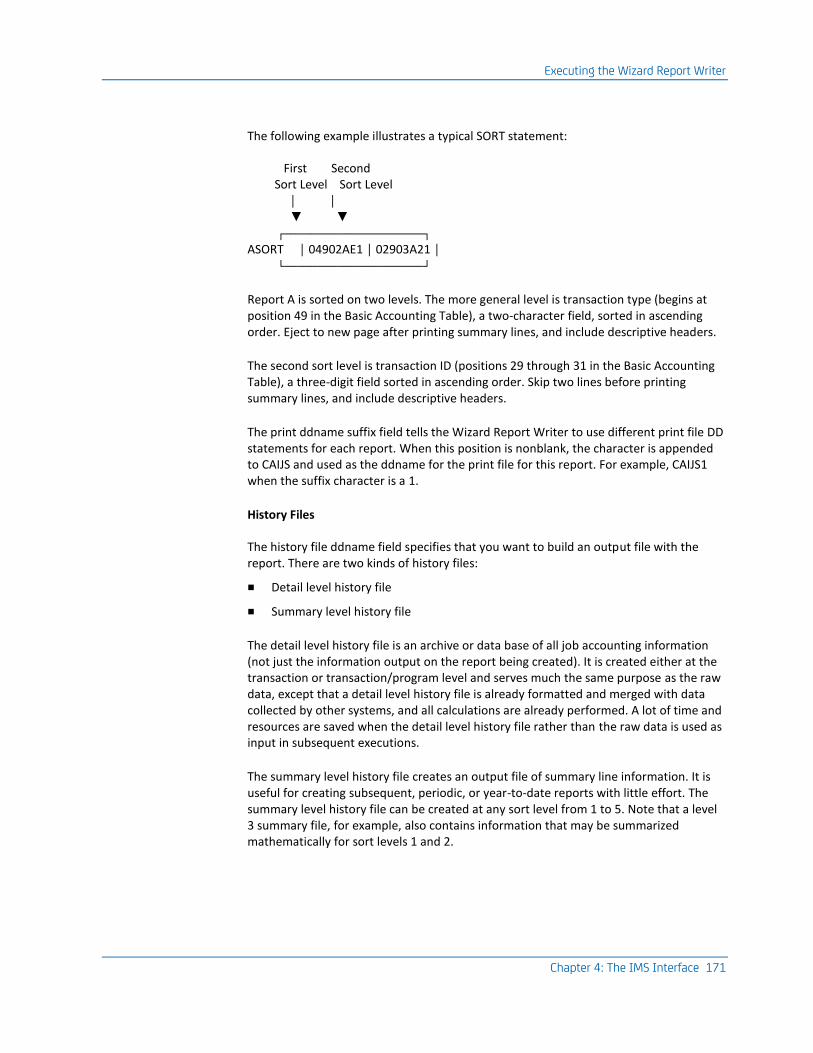
Executing the Wizard Report Writer
Chapter 4: The IMS Interface 171
The following example illustrates a typical SORT statement:
First Second Sort Level Sort Level │ │ ▼ ▼ ┌─────────────────────┐ ASORT │ 04902AE1 │ 02903A21 │ └─────────────────────┘
Report A is sorted on two levels. The more general level is transaction type (begins at position 49 in the Basic Accounting Table), a two-character field, sorted in ascending order. Eject to new page after printing summary lines, and include descriptive headers.
The second sort level is transaction ID (positions 29 through 31 in the Basic Accounting Table), a three-digit field sorted in ascending order. Skip two lines before printing summary lines, and include descriptive headers.
The print ddname suffix field tells the Wizard Report Writer to use different print file DD statements for each report. When this position is nonblank, the character is appended to CAIJS and used as the ddname for the print file for this report. For example, CAIJS1 when the suffix character is a 1.
History Files
The history file ddname field specifies that you want to build an output file with the report. There are two kinds of history files:
■ Detail level history file
■ Summary level history file
The detail level history file is an archive or data base of all job accounting information (not just the information output on the report being created). It is created either at the transaction or transaction/program level and serves much the same purpose as the raw data, except that a detail level history file is already formatted and merged with data collected by other systems, and all calculations are already performed. A lot of time and resources are saved when the detail level history file rather than the raw data is used as input in subsequent executions.
The summary level history file creates an output file of summary line information. It is useful for creating subsequent, periodic, or year-to-date reports with little effort. The summary level history file can be created at any sort level from 1 to 5. Note that a level 3 summary file, for example, also contains information that may be summarized mathematically for sort levels 1 and 2.

Executing the Wizard Report Writer
172 Interfaces Guide
The history level flag field set in the SORT statement defines the kind of history file you want created and at which level. A level 1-5 flag refers to the corresponding sort control level for a summary level history file. A level 6 or 7 flag indicates that detail level history data is to be created at the transaction (6) or the transaction/program (7) level.
SORT Statement Layout
Statement Position
Field Length
Field Name Notes
1 1 Set Code Required
2 8 Statement Type SORT
10-17
18-25
26-33
34-41
42-49
8
8
8
8
8
1st Sort Level
2nd Sort Level
3rd Sort Level
4th Sort Level
5th Sort Level
pppllosd must be blank or numeric where pppllosd:
ppp: Position of sort field from
Basic Accounting Table
ll: Length of sort field (max 8)
o: Order of sort field
A = ascending (default)
D = descending
s: Summary Line Print Option:
see table below
d: Description Header Flag:
= suppress printing
1= print Description Headers for
this level
50 51
1 1
Transaction Flag Program Flag
= suppress printing 1= print records
52-53 2 Reserved
54 1 Required Records Indicator J: Transaction records only S: Program records only
55-62 8 History File DDName = No history file xxxxxxxx = History file ddname
63 1 History Level Flag 1-5 = Summary level history file 6 = Transaction level hist file 7 = Transaction/Program hist file
64 1 Print DDName Suffix If nonblank, append to ddname of 'PRINT' and use that ddname for the report output
65-80 16 Reserved Not used

Executing the Wizard Report Writer
Chapter 4: The IMS Interface 173
Statement Position
Field Length
Field Name Notes
Summary Line Print Option Table N or - No summary print for this level 1, 2, or 3 - Single, double, or triple space before printing summary E* - Eject to new page after printing summary P* - Eject to new page and reset pg. no. after printing summary
* If either E or P is specified for the first level summary line, then grand totals print on a page by themselves.
TITLE Statement
This statement, identified by the statement type TITLE, is optional. It provides a mechanism by which you may override the predefined default titles of output data elements available for display. Each TITLE statement overrides one specific element title. Multiple statements may be used as required.
The data element ID field specifies which entry in the Output Data Elements Table is to have its title changed.
The top line title field is a twenty (20) character field available to you to override the top line of data element titles. The bottom line title field is used to override the bottom line of titles. User-defined titles may not exceed the output length of the corresponding data element as defined in the table.
TITLE statements with a set code in statement position 1 apply to that report only. TITLE statements can be made to override the standard titles for all reports that use the affected data elements by leaving statement position one blank.
Statement Position
Field Length
Field Name Notes
1 1 Set Code Optional
2-9 8 Statement Type TITLE
10-11 2 Data Element ID
12-31 20 Top Line Title
32-51 20 Bottom Line Title

Data Element Directory
174 Interfaces Guide
Data Element Directory
The IMS Interface translated data is in a format that the Wizard Report Writer recognizes as a level-7 summary record. The IMS Interface summary record exists only to enable the Wizard Report Writer to generate IMS Interface reports by using the same powerful reporting capabilities as the Job Accounting Report System batch reporting.
There are three main reporting functions:
■ data accumulation
■ sorting
■ displaying data elements
Because each of these functions treats IMS data in a manner related to the function (such as displaying data elements deals with an external data element format), the IMS Interface summary record is shown in three ways in this directory: the physical summary record format, a Basic Accounting Table, and an Output Data Elements Table.
Summary Record Format
This is the format of IMS Interface data as input to the Wizard Report Writer.
You may change IMS Interface data within the summary record using exits to the Wizard Report Writer. You may also add data elements to the summary record for special application-related reporting.
If you change or add data within the summary record, the format of the record must be maintained exactly as specified in this table. The Wizard Report Writer operates on all data elements, and does not treat records that have improper data (such as EBCDIC data in a packed decimal field), or may give unexpected results (such as unnoted truncations of printed data).
The following table shows the format of the summary record. The final column provides the corresponding Output Data Element ID for the Summary Record.
IMS Interface Summary Record Format:
Field Name Len Displ Mode Notes Output DE ID
CPU Identification 1 0 EBCDIC 57
Reserved 2 1
Date Record Written 6 3 EBCDIC YYMMDD 60
Time Record Written 6 9 EBCDIC HHMMSS 61

Data Element Directory
Chapter 4: The IMS Interface 175
Field Name Len Displ Mode Notes Output DE ID
Job Name 8 15 EBCDIC 04
Reserved 2 23
Transaction Count 2 25 Binary 56
Processing ID 1 27 EBCDIC C 03
Transaction ID 8 28 EBCDIC 10
Trans Stop Time 6 36 EBCDIC HHMMSS 12
Trans Stop Date 6 42 EBCDIC YYMMDD 06
Trans Type 2 48 EBCDIC Message Region/Batch Message Region Transaction Indicator
07
Reserved 6 50
User ID 8 56 EBCDIC 58
Reserved 12 64
User Information 16 76 EBCDIC 08
Abend Code 4 92 EBCDIC 09
Reserved 2 96
Step Name 8 98 EBCDIC 11
PSB Name 8 106 EBCDIC 05
Reserved 18 114
Total Message Gets 6 132 Packed 18
Reserved 6 138
Total DL/I Operations 6 144 Packed 19
Total Message Inserts 6 150 Packed 20
Reserved 14 156
Elapsed Time 6 170 Packed xxxxxvxxxxxc minutes
25 65 90
Application CPU Time 6 176 Packed xxxxxvxxxxxc minutes
26 66 91
Reserved 37 182 Packed

Data Element Directory
176 Interfaces Guide
Field Name Len Displ Mode Notes Output DE ID
Terminal Messages 7 219 Packed 34
Reserved 7 226
GU/GHU DLI Counts 7 233 Packed 37
GN/GHN DLI Counts 7 240 Packed 38
GNP/GHNP DLI Counts 7 247 Packed 39
Total DLI Gets 7 254 40
Reserved 34 261
Group Code #1 Group Code #2 Group Code #3
1 1 1
295 296 297
EBCDIC Blank unless filled by grouping feature
84 85 86
Reserved 2 298
Logical terminal ID 8 300 EBCDIC 58
Reserved 12 308
ISRT DLI Count 7 320 Packed A1
DLET DLI Count 7 327 Packed A2
REPL DLI Count 7 334 Packed A3
Reserved 87 341
Priority 3 428 EBCDIC B6
Storage Protect Key 3 431 EBCDIC B7
Reserved 3 434
Time fields are recorded in 100000ths of a minute.
CA JARS IMS Basic Accounting Table
IMS Interface summary record data is used by the Wizard Report Writer for several report control functions other than the actual display of data. Such functions as multilevel sort control, data grouping, and record selection/rejection are driven from the summary record data as presented in the Basic Accounting Table (BAT).

Data Element Directory
Chapter 4: The IMS Interface 177
The following table shows the Basic Accounting Table format and pertinent accounting characteristics of IMS Interface summary record data. The final column provides the corresponding Output Data Element ID for the IMS Basic Accounting Table.
IMS Interface Basic Account Table:
BAT Field Position BAT Field Length
Format Indicator
Field Name Notes Output DE ID
1 1 a CPU Identification
57
2-3 2 - Reserved Nonblank characters
4-9 6 a Date Record Written
YYMMDD 60
10-15 6 a Time Record Written
HHMMSS 61
16-23 8 a Job Name 04
26-27 2 x Transaction Count
Will be program use count in program records for basic mode collection
56
28 1 a Processing ID C 03
29-36 8 a Transaction ID 10
37-42 6 a Trans Stop Time HHMMSS 12
43-48 6 a Trans Stop Date YYMMDD 06
49-50 2 a Trans Type Message/Batch Message Region Transaction Indicator
07
51-56 6 - Reserved
57-76 20 a USERID USERID present only if user has signed on to IMS through RACF, CA TOP SECRET or other security system
58
77-92 16 a User Information 08

Data Element Directory
178 Interfaces Guide
BAT Field Position BAT Field Length
Format Indicator
Field Name Notes Output DE ID
93-96 4 a Abend Code 09
97-98 2 - Reserved
99-106 8 a Step Name 11
107-114 8 a PSB Name 05
115-132 18 - Reserved
133-138 6 p Total Message Gets
18
139-144 6 - Reserved
145-150 6 p Total DL/I IO counts
19
151-156 6 p Total Message Inserts
20
157-170 14 - Reserved
171-176 6 p Elapsed Time xxxxxxxvxxxxxc minutes
25, 65, 90
177-182 6 p Application CPU Time
xxxxxxxvxxxxxc minutes
26 66, 91
183-219 37 - Reserved
220-226 7 p Terminal Messages
34
227-233 7 - Reserved
234-240 7 p GU/GHU DLI Counts
37
241-247 7 p GN/GHN DLI Counts
38
248-254 7 p GNP/GHNP DLI Counts
39
255-261 7 p Total DLI Gets 40
262-295 34 - Reserved
296 297 298
1 1 1
a a a
Group Code #1 Group Code #2 Group Code #3
Blank unless filled by grouping feature
84 85 86

Data Element Directory
Chapter 4: The IMS Interface 179
BAT Field Position BAT Field Length
Format Indicator
Field Name Notes Output DE ID
299-300 2 - Reserved
301-308 8 a Input logical terminal ID
IMS 1.3 and above, MPPs only. Blank or BMPs.
A0
309-320 12 - Reserved
321-327 7 p ISRT DLI Count A1
328-334 7 p DLET DLI Count A2
335-341 7 p REPL DLI Count A3
342-428 87 - Reserved
429-431 3 a Priority B6
432-434 3 a Storage Protect Key
B7
435-437 3 - Reserved
* Format Indicator: a=alphanumeric, P=packed decimal, X=hexadecimal binary
CA JARS IMS Output Data Elements Table
IMS Interface summary record data elements are converted into printable EBCDIC formats for report printing. The Output Data Elements Table (ODE) contains all the print images of the IMS Interface data elements. You can examine or modify data elements within this table before the printing of every line by use of a Wizard Report Writer type 3 exit. See the CA JARS User Guide.
This table also contains several printable data elements that do not represent direct conversions of data elements within the IMS Interface summary record. These calculated data elements are also available for examination or modification by user exit logic.
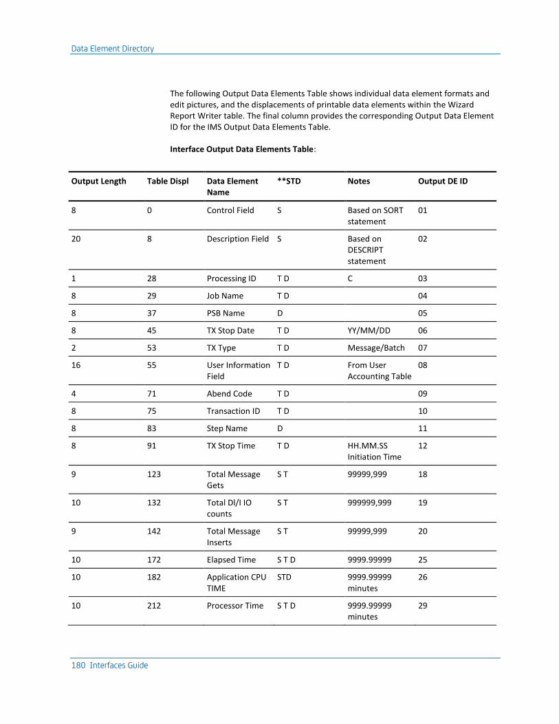
Data Element Directory
180 Interfaces Guide
The following Output Data Elements Table shows individual data element formats and edit pictures, and the displacements of printable data elements within the Wizard Report Writer table. The final column provides the corresponding Output Data Element ID for the IMS Output Data Elements Table.
Interface Output Data Elements Table:
Output Length Table Displ Data Element Name
**STD Notes Output DE ID
8 0 Control Field S Based on SORT statement
01
20 8 Description Field S Based on DESCRIPT statement
02
1 28 Processing ID T D C 03
8 29 Job Name T D 04
8 37 PSB Name D 05
8 45 TX Stop Date T D YY/MM/DD 06
2 53 TX Type T D Message/Batch 07
16 55 User Information Field
T D From User Accounting Table
08
4 71 Abend Code T D 09
8 75 Transaction ID T D 10
8 83 Step Name D 11
8 91 TX Stop Time T D HH.MM.SS Initiation Time
12
9 123 Total Message Gets
S T 99999,999 18
10 132 Total Dl/I IO counts
S T 999999,999 19
9 142 Total Message Inserts
S T 99999,999 20
10 172 Elapsed Time S T D 9999.99999 25
10 182 Application CPU TIME
STD 9999.99999 minutes
26
10 212 Processor Time S T D 9999.99999 minutes
29
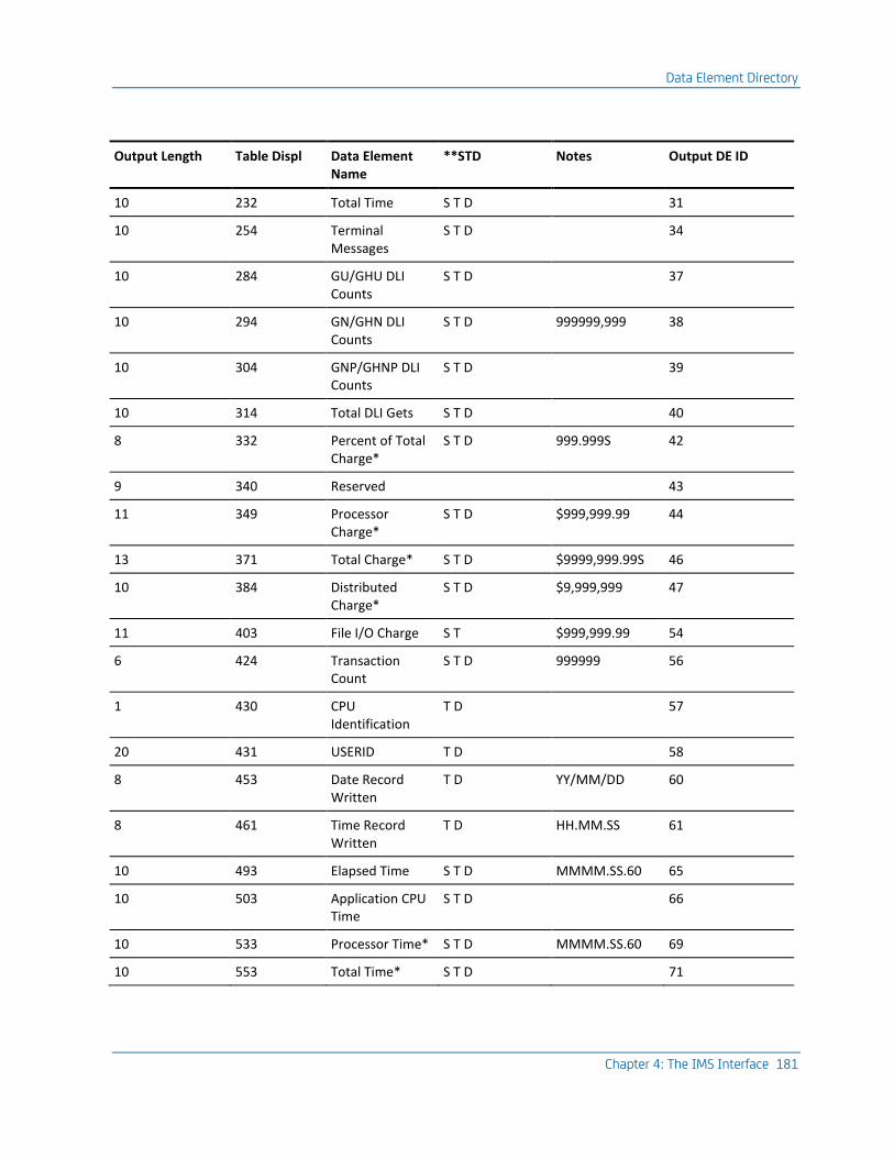
Data Element Directory
Chapter 4: The IMS Interface 181
Output Length Table Displ Data Element Name
**STD Notes Output DE ID
10 232 Total Time S T D 31
10 254 Terminal Messages
S T D 34
10 284 GU/GHU DLI Counts
S T D 37
10 294 GN/GHN DLI Counts
S T D 999999,999 38
10 304 GNP/GHNP DLI Counts
S T D 39
10 314 Total DLI Gets S T D 40
8 332 Percent of Total Charge*
S T D 999.999S 42
9 340 Reserved 43
11 349 Processor Charge*
S T D $999,999.99 44
13 371 Total Charge* S T D $9999,999.99S 46
10 384 Distributed Charge*
S T D $9,999,999 47
11 403 File I/O Charge S T $999,999.99 54
6 424 Transaction Count
S T D 999999 56
1 430 CPU Identification
T D 57
20 431 USERID T D 58
8 453 Date Record Written
T D YY/MM/DD 60
8 461 Time Record Written
T D HH.MM.SS 61
10 493 Elapsed Time S T D MMMM.SS.60 65
10 503 Application CPU Time
S T D 66
10 533 Processor Time* S T D MMMM.SS.60 69
10 553 Total Time* S T D 71

Data Element Directory
182 Interfaces Guide
Output Length Table Displ Data Element Name
**STD Notes Output DE ID
12 606 Credit Amount S T D $9999,999.99 based on CREDIT statements
79
12 618 Debit Amount S T D $9999,999.99 based on DEBIT statements
80
10 630 Budget Amount S T D $9,999,999 81
13 640 Over-Under Budget
S $9999,999.99 based on BUDGET statements
82
6 653 Percent Budget Spent
S 9999.9 83
1 1 1
659 660 661
Group Code #1 Group Code #2 Group Code #3
T D T D T D
Blank unless filled by grouping feature
84 85 86
8 684 Elapsed Time-Avg
S T D HH.MM.SS 90
8 692 Appl. CPU-Time Avg
S T D 91
10 714 Blank Spaces S T D May be used to adjust print line
99
8 724 Logical Terminal ID
T D A0
10 732 ISRT DLI Counts S T D 999999,999 A1
6 742 DLET DLI Counts S T D A2
7 752 REPL DLI Counts S T D A3
3 865 Priority T D B6
3 868 Storage Protect Key
T D B7
**STD = Summary, Transaction, and Detail levels, respectively.
* Data element not available unless RATE parameters specified for report.
Chapter 5: The Network Accounting Interface 183
Chapter 5: The Network Accounting Interface
The Network Accounting Interface provides a mechanism for:
■ Accounting for network system usage
■ Adding network charges to your reports
The data used to assess and charge network cost is obtained from either CA Mazdamon or IBM NETVIEW. This guide describes how to manipulate IBM NETVIEW and CA Mazdamon data through CA JARS and CA JARS Wizard.
Note: The Network Accounting Interface uses the Wizard Report Writer to read the IBM NETVIEW and CA Mazdamon session file extract records. Two CA JARS Wizard glossaries, JR71CBF and JR71CB2, are provided for this purpose. Two sample reports, created using CA JARS Wizard, are also provided with the interface.
This section contains the following topics:
Daily Processing for CA Mazdamon (see page 183) Daily Processing for IBM NETVIEW (see page 183) Operating Instructions (see page 184) Sample Report - JSINET1 (see page 187) Sample Report - JSINET2 (see page 192) CA Mazdamon and IBM NETVIEW Data Elements (see page 195) EXTDATA Reports (see page 197)
Daily Processing for CA Mazdamon
The CA Mazdamon daily run can be set to produce an output file called the session file. CA Mazdamon users must activate the CA JARS switch in the CA Mazdamon Daily2 routine in order to receive the session file output. This file is optional output for the CA Mazdamon daily summary data base. There is one record per user session that shows the network activity for that user in terms of messages and characters transmitted. On a daily basis, these session records are written to a new generation of this data set and accumulated until the end of the billing period.
Daily Processing for IBM NETVIEW
The data used to assess and charge IBM NETVIEW cost is obtained from the session monitor records written to the SMF log file as type 39 records. To record data that the session monitor collects, see the IBM NETVIEW Installation and Administration Guide.

Operating Instructions
184 Interfaces Guide
Once the SMF type 39 records are written to the SMF log file, CA JARS can be coded to extract these records and create a new generation of the session file during a single pass of the SMF data. The session file produced by IBM NETVIEW has the same format as the file produced by CA Mazdamon Daily2 run.
The SMF type 39 log records are processed by the CA JARS NETVIEW extract program (JSZT0000). An optional feature of the report writer is activated either by coding a Y (yes) in position 41 of the OPTION statement. or by coding a Y (yes) in positions 10 and 46 of the EXTDATA statement. The exit produces one required file, ddname CAIJMSFX. This file contains the IBM NETVIEW accounting extract for subsequent processing by the Wizard Report Writer. All IBM NETVIEW accounting data elements from the SMF record are included in the extract record. Therefore, you can use it for more than just chargeback accounting.
The CAIJMSFX file has the following characteristics:
RECFM=FB
LRECL=200
BLKSIZE=4000 (default)
However, the DD statement can be changed to any acceptable BLKSIZE desired.
In addition, EXTDATA records that can be processed by CA EARL and CA Easytrieve can also be generated. To do this you must include an EXTDATA card in the CA JARS control statements, and have columns 10 and 46 set to Y. This will generate NETVIEW EXTDATA records and write them to the CA JARS Accounting file (CAIJSACT).
For EXTDATA production, it is not required that the IBM NETVIEW extract option be set on the OPTION statement (column 41 set to Y).
Operating Instructions
Two reports are generated by the interface:
JSINET1:
shows how debit records can be created. These debit records are read in a product run that reports on charges by account. Network usage charges are added to the other charges that are calculated on an account basis.
JSINET2:
shows network usage by terminal ID.
JSINET3
provides sample control statements for processing of IBM NETVIEW data into CA JARS.

Operating Instructions
Chapter 5: The Network Accounting Interface 185
Each report and the CA JARS Wizard glossary for the interface are described on the following pages.
The source code for both of these CA JARS Wizard programs is distributed in the AAJ1OPTN distribution library and is copied to CAJROPTN at APPLY time by SMP. You are encouraged to use these as samples and develop your own CA JARS Wizard applications against either CA Mazdamon or IBM NETVIEW data. However, you should avoid modifying the distributed source other than via official maintenance.
JSINET1: Debit Record Creation
In JSINET1, CA JARS Wizard is used to:
■ Get accounting information for each network user using their terminal ID and a CA JARS Wizard facility called file matching. This involves CA JARS Wizard searching a second file to find the accounting information associated with each terminal ID. Complete information on file matching can be found in the Wizard Reference Guide.
■ Calculate the charge for the user. In this sample the charge is based on number of characters and number of messages transmitted to and from the terminal. Because CA JARS Wizard has a flexible language for computing new fields, the charge can be based on anything in the record. for instance, a surplus could be charged for network usage during peak hours.
■ Sum the charges for the accounts and print a report that shows the charge by account.
■ Write a debit record for each account. This debit record contains the account information and the calculated charge. All debit records are read in a product run that reports on charges by account. The charge for using the network is added to the other charges that is calculated on an account basis.
JSINET1 executes on the assumption that you have a secondary file containing one record for each unique terminal ID at your site. Each record in this secondary file also contains the necessary debit record accounting information. Report JSINET1 assumes that the Terminal ID is in positions 1 to 8 and the accounting information is in positions 10 to 25, as follows:
1 2 2
1........0.........0....5
terminal accounting info.
ID
If you do not have such a file, you must set one up or alter the JSINET1 control statements accordingly.
A sample of this file is located in CAJROPTN member JSINET1.

Operating Instructions
186 Interfaces Guide
To execute JSINET1, set up the necessary JCL for the run. Be sure to include DD statements for the following ddnames:
■ CAIJWI (your session file)
■ CAIJWI2 (the secondary file containing account information)
■ CAIJWOP (the output file for the debit records)
The sample report produced with the debit record output file when JSINET1 is shown on the next page.

Sample Report - JSINET1
Chapter 5: The Network Accounting Interface 187
Sample Report - JSINET1
JSINET1 Report - charges by account number.:
CA PROGRAM LISTING
CA JARS Wizard 9710JW230
TOTAL NETWORK CHARGES BY ACCOUNT 28 OCT 1998 PAGE 1
CHARACTERS MESSAGES TERMINAL APPLICATION
ACCOUNT TOTAL CHARGE TRANSMITTED TRANSMITTED ID ID
---------------- -------------- -------------- -------------- -------- -----------
ACCOUNTING $39,707.04 721,759.00 82.00
DEVELOPMENT $177,008.20 3,215,321.00 1,319.00
SALES $12,076.13 219,429.00 60.00
. . . . . .
. . . . . .
. . . . . .
TOTAL NETWORK CHARGES BY ACCOUNT 28 OCT 1998 PAGE 13
CHARACTERS MESSAGES TERMINAL APPLICATION
ACCOUNT TOTAL CHARGE TRANSMITTED TRANSMITTED ID ID
---------------- -------------- -------------- -------------- -------- -----------
GRAND TOTAL $11,375,991.62 206,699,314.00 59,992.00
CA EXECUTION STATISTICS
CA JARS Wizard 9710JW230
CAJW200I 1067 SORTED INPUT 9:20:55 START
CAJW202I 557 OUTPUT RECORDS 9:20:59 END
CAJW205I 1067 PRE-SORT RECORDS :04 DURATION
CAJW206I 1067 SELECTED RECORDS
CAJW211I 21 MATCHED RECORDS
CAJW212I 4268 COMPUTATIONS
CAJW213I 16 FILE 2 RCDS READ
CAJW214I 21 FILE 2 MATCHED
CAJW215I 1046 FILE 2 MISSING
CAJW216I 557 LEVEL 1 BREAKS
CAJW217I 98 SORT RCD LENGTH
CAJW219I 88960 ADDTL CORE USED
FORMAT OF NEW RECORD
POSITION BYTES FORMAT DESCR
001 1 1 CHAR OFILL1
002 2- 9 8 CHAR ODEBIT
003 10 1 CHAR OCPUID
004 11- 18 8 CHAR OTERMINALID
005 19- 34 16 CHAR OACCT
006 35- 40 6 CHAR ODATE
007 41- 48 8 CHAR OJOB
008 49- 54 6 CHAR OTIME
009 55- 74 20 CHAR OPROGRAMMER
010 75- 80 6 PACKED .2 ODEBITAMT

Sample Report - JSINET1
188 Interfaces Guide
JSINET1 Control Statements:
PARAMETER XREF NOPC
*
DEFINE OFILL1(1)(C) = ' '
DEFINE ODEBIT(8)(C) = 'DEBIT '
DEFINE OCPUID(1)(C) = ' '
DEFINE OTERMINALID(8)(C) = ' '
DEFINE ODATE(6)(C) = ' '
DEFINE OJOB(8)(C) = 'NETWORK '
DEFINE OTIME(6)(C) = ' '
DEFINE OPROGRAMMER(20)(C) = ' '
DEFINE ODEBITAMT(6)(P)(.2) = 0
*
DEFINE NETMESSAGES(6)(P)(.2) = 0
DEFINE NETCHARACTERS(6)(P)(.2) = 0
*
INPUT JR70CBF
SELECT REC/TYPE EQ '8'
*
INPUT FILE KEY = 2CC1-8 MATCH = TERMINAL/ID TABLE=2CC10-25 LIST
COMPUTE(P) IF MATCHED THEN OACCT(C)(16) EQ 2CC10-25 ELSE
OACCT(C)(16) EQ TERMINAL/ID
*
COMPUTE NETMESSAGES = 8.MESS/TRANS/IN + 8.MESS/TRANS/OUT
COMPUTE NETCHARACTERS = 8.CHAR/TRANS/IN + 8.CHAR/TRANS/OUT
*
COMPUTE ODEBITAMT = (NETMESSAGES * .1255) + (NETCHARACTERS * .055)
COMPUTE ODEBITC(6)(N)(.2)=ODEBITAMT
*
SORT OACCT
BREAK OACCT
HEADING1C TOTAL NETWORK CHARGES BY ACCOUNT
LIST(SUM) OACCT(DL) 'ACCOUNT',
ODEBITAMT($) 'TOTAL CHARGE',
NETCHARACTERS 'CHARACTERS/TRANSMITTED',
NETMESSAGES 'MESSAGES/TRANSMITTED',
TERMINAL/ID,A.APPLICATION/ID
*
OUTPUT FILE,RECFM = FB,R = 80,B = 800,
ITEM = OFILL1,
ODEBIT,
OCPUID,
OTERMINALID,
OACCT,
ODATE,
OJOB,
OTIME,
OPROGRAMMER,
ODEBITC

Sample Report - JSINET1
Chapter 5: The Network Accounting Interface 189
JSINET1 Execution Description
The control statements used in JSINET1 are described below. Complete descriptions of all CA JARS Wizard control statements can be found in your CA JARS Wizard Reference Guide.
PARAMETER
The PARAMETER control statement specifies options for a CA JARS Wizard run.
XREF
creates a cross-reference of the data fields used in the run and the statements they are found in. This cross-reference listing is printed in addition to the control statements and the report for the run.
NOPC
suppresses the CA JARS Wizard error handling routine.
INPUT
INPUT statements are used to identify the CA JARS Wizard glossary and/or the input files for the run. In JSINET1 two INPUT statements are given:
■ The first INPUT statement lists the JR70CBF glossary as the glossary for the primary input file for the run.
■ The second INPUT statement describes the secondary input file. Secondary files are only used when file matching is to be performed.
KEY = 2CC1-8
defines the matching key field for the secondary file. Here, the first eight positions for each record are the matching key.
MATCH =
TERMINAL/ID
designates the terminal ID field of the primary input file as its matching key field.
TABLE
indicates that the secondary input file is a table file to be read completely at the start of the run. Therefore, the entire file is available for searching during the run. The field in positions 10 through 25 of the secondary file contains the account information.
The notation 2CC10-25 serves two purposes:
■ Identifies the location of a data field in the secondary file
■ Serves as a name for the field

Sample Report - JSINET1
190 Interfaces Guide
SELECT
The SELECT statement identifies the record type of the Network Accounting Billing Records.
DEFINE
Eleven DEFINE statements are given in JSINET1. Each defines a field for the run. All of the defined fields are initialized each time a new record is processed. The first nine DEFINE statements define fields for the debit record. There are:
1. OFILL1:
One-byte filler field, initialized as a blank.
2. ODEBIT:
Eight-byte field, initialized as DEBIT. This field identifies the CA JARS record as a DEBIT record.
3. OCPUID:
One-byte field, initialized as a blank, and used to identify the CPU.
4. TERMINALID:
Eight-byte field, initialized as blanks, and used for terminal identification.
5. ODATE:
Six-byte field, initialized as blanks, and used for the date (YYMMDD).
6. OJOB:
Eight-byte field, initialized as blanks, and used for the job name.
7. OTIME:
Six-byte field, initialized as blanks, and used for the time (HHMMSS).
8. OPROGRAMMER:
20-byte field, initialized as blanks, and identifying the programmer.
9. ODEBITAMT:
Six-byte field, initialized to zero, and used for the debit amount.
10. NETMESSAGE:
Six-byte field, used to hold the sum of the network messages transmitted.
11. NETCHARACTERS:
Six-byte field, used to hold the sum of the network characters transmitted.
COMPUTE
Four COMPUTE statements are executed in JSINET1.
Sample Report - JSINET1
Chapter 5: The Network Accounting Interface 191
The first COMPUTE statement evaluates the file matching between the primary input file and the secondary file. It also defines a new field OACCT(16 bytes) and assigns a value to it based on the results of file matching. If a match occurs on the terminal/ID of a primary input file record and a secondary input file record, OACCT is assigned the value of the account information in positions 10 to 25 of the secondary file. Otherwise, OACCT is assigned a value of the terminal/ID.
Notice the (P) suffix code appended to the first COMPUTE statement. This code indicates that the COMPUTE should take place before the primary input file records are sorted. This is necessary because the SORT occurs on the OACCT field.
The remaining three COMPUTE statements simply assign values to fields: NETMESSAGES, NETCHARACTERS, and OTERMINALID. OTERMINALID is assigned the value of TERMINAL/ID in the primary input record. NETMESSAGES and NETCHARACTERS are calculated from other fields in the primary input record.
SORT
The SORT statement identifies the sequence in which the input records should be sorted prior to processing. Here the SORT is performed on OACCT (the account information). Note that the OACCT field is created and assigned a value in the COMPUTE(P) statement before the SORT.
BREAK
BREAK statements define logical groups of records. Here data is split into groups by OACCT. Records with the same account information are grouped together.
A SORT statement must be included in a CA JARS Wizard run when a BREAK statement is used. The fields specified in the BREAK statement must be included in the SORT statement and must be specified in the same order as the SORT statement.
HEADING
HEADING specifies a title for the report. Here the title for the report (created in addition to the output file) is TOTAL NETWORK CHARGES BY ACCOUNT.
LIST(SUM)
A summary listing is requested along with the output file. Each line of the summary listing list debit information for a different account. The LIST(SUM) statement identifies the data fields to be summarized and printed. This data includes the:
■ Account identifier (information)
■ Calculated total charge
■ Calculated total characters
■ Total messages sent
Sample Report - JSINET2
192 Interfaces Guide
OUTPUT
One debit record is produced for each unique account. All records are written to the file identified by ddname CAIJWOP. The OUTPUT statement lists the fields to be included in each debit record.
Sample Report - JSINET2
JSINET2 is a sample report showing how you can use the JR70CBF glossary and your CA Mazdamon or IBM NETVIEW session file data to create CA JARS reports. A sample of the output from JSINET2 is shown below:
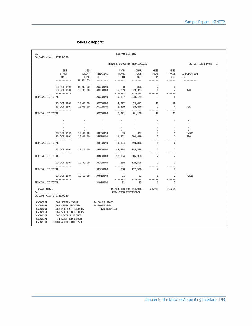
Sample Report - JSINET2
Chapter 5: The Network Accounting Interface 193
JSINET2 Report:
CA PROGRAM LISTING
CA JARS Wizard 9710JW230
NETWORK USAGE BY TERMINAL/ID 27 OCT 1998 PAGE 1
SES SES CHAR CHAR MESS MESS
START START TERMINAL TRANS TRANS TRANS TRANS APPLICATION
DATE TIME ID IN OUT IN OUT ID
----------- HH:MM:SS -------- ------- ------- ------- ------- -----------
23 OCT 1994 08:00:00 ACXCW0A0 8 806 2 6
23 OCT 1994 16:30:00 ACXCW0A0 15,389 829,323 1 2 A2K
----------- ------- ------- ------- -------
TERMINAL ID TOTAL ACXCW0A0 15,397 830,129 3 8
23 OCT 1994 10:00:00 ACXDW0A0 4,322 24,612 10 19
23 OCT 1994 16:00:00 ACXDW0A0 1,899 56,496 2 4 A2K
----------- ------- ------- ------- -------
TERMINAL ID TOTAL ACXDW0A0 6,221 81,108 12 23
. . . . . . . .
. . . . . . . .
. . . . . . . .
. . . . . . . .
23 OCT 1994 15:40:00 XFF0W0A0 33 427 4 5 MVS15
23 OCT 1994 15:40:00 XFF0W0A0 11,361 693,439 2 1 TSO
----------- ------- ------- ------- -------
TERMINAL ID TOTAL XFF0W0A0 11,394 693,866 6 6
23 OCT 1994 16:10:00 XFNCW0A0 58,764 386,368 2 2
----------- ------- ------- ------- -------
TERMINAL ID TOTAL XFNCW0A0 58,764 386,368 2 2
23 OCT 1994 12:40:00 XF38W0A0 368 122,506 2 2
----------- ------- ------- ------- -------
TERMINAL ID TOTAL XF38W0A0 368 122,506 2 2
23 OCT 1994 16:10:00 XX01W0A0 31 93 1 2 MVS15
----------- ------- ------- ------- -------
TERMINAL ID TOTAL XX01W0A0 31 93 1 2
GRAND TOTAL 15,484,328 191,214,986 28,723 31,269
CA EXECUTION STATISTICS
CA JARS Wizard 9710JW230
CAJW200I 1067 SORTED INPUT 14:50:28 START
CAJW203I 1067 LINES PRINTED 14:50:57 END
CAJW205I 1067 PRE-SORT RECORDS :29 DURATION
CAJW206I 1067 SELECTED RECORDS
CAJW216I 563 LEVEL 1 BREAKS
CAJW217I 71 SORT RCD LENGTH
CAJW219I 80784 ADDTL CORE USED
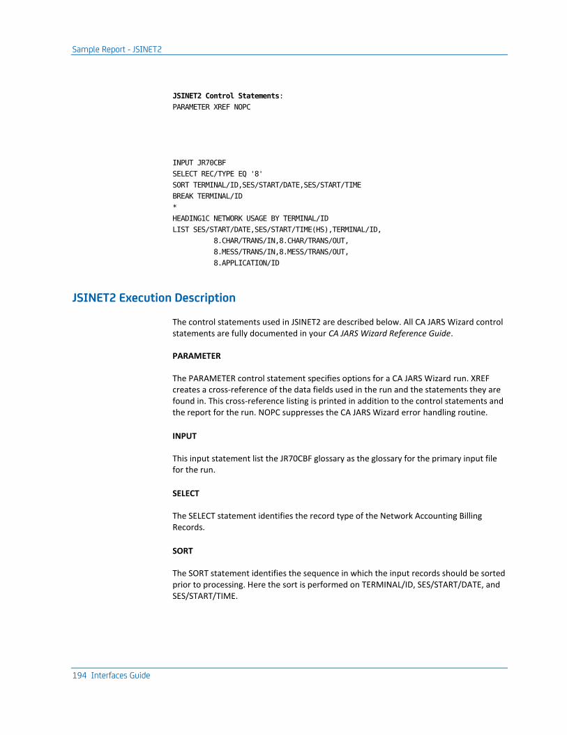
Sample Report - JSINET2
194 Interfaces Guide
JSINET2 Control Statements:
PARAMETER XREF NOPC
INPUT JR70CBF
SELECT REC/TYPE EQ '8'
SORT TERMINAL/ID,SES/START/DATE,SES/START/TIME
BREAK TERMINAL/ID
*
HEADING1C NETWORK USAGE BY TERMINAL/ID
LIST SES/START/DATE,SES/START/TIME(HS),TERMINAL/ID,
8.CHAR/TRANS/IN,8.CHAR/TRANS/OUT,
8.MESS/TRANS/IN,8.MESS/TRANS/OUT,
8.APPLICATION/ID
JSINET2 Execution Description
The control statements used in JSINET2 are described below. All CA JARS Wizard control statements are fully documented in your CA JARS Wizard Reference Guide.
PARAMETER
The PARAMETER control statement specifies options for a CA JARS Wizard run. XREF creates a cross-reference of the data fields used in the run and the statements they are found in. This cross-reference listing is printed in addition to the control statements and the report for the run. NOPC suppresses the CA JARS Wizard error handling routine.
INPUT
This input statement list the JR70CBF glossary as the glossary for the primary input file for the run.
SELECT
The SELECT statement identifies the record type of the Network Accounting Billing Records.
SORT
The SORT statement identifies the sequence in which the input records should be sorted prior to processing. Here the sort is performed on TERMINAL/ID, SES/START/DATE, and SES/START/TIME.

CA Mazdamon and IBM NETVIEW Data Elements
Chapter 5: The Network Accounting Interface 195
BREAK
BREAK statements define logical groups of records. Here data is split into groups by user ID. Records with the same TERMINAL/ID are grouped together.
HEADING
HEADING specifies a title for the report. Here the title for the report (created in addition to the output file) is: NETWORK USAGE BY TERMINAL ID.
LIST
The LIST statement identifies the data element to be printed. This includes:
■ Session start date
■ Session start time
■ Terminal ID
■ Number of characters transmitted in
■ Number of characters transmitted out
■ Number of messages transmitted in
■ Number of messages transmitted out
■ Application ID
CA Mazdamon and IBM NETVIEW Data Elements
Name Pos Len Format Description
RCD DESCRIPTOR 1 4 B Record length from RDW
SMF/ID 5 4 C SMF ID
SES/START/DATE 9 3 P Session start date yyddd
SES/START/TIME 12 8 P Session start time
GREG/DATE 23 6 C Start date yymmdd
TERMINAL/ID 29 8 C Terminal ID (session ID)
START/DATE 37 3 P Start Date yyddd
START/TIME 40 8 P Start time
STOP/DATE 48 3 P Stop date yyddd
STOP/TIME 51 8 P Stop Time
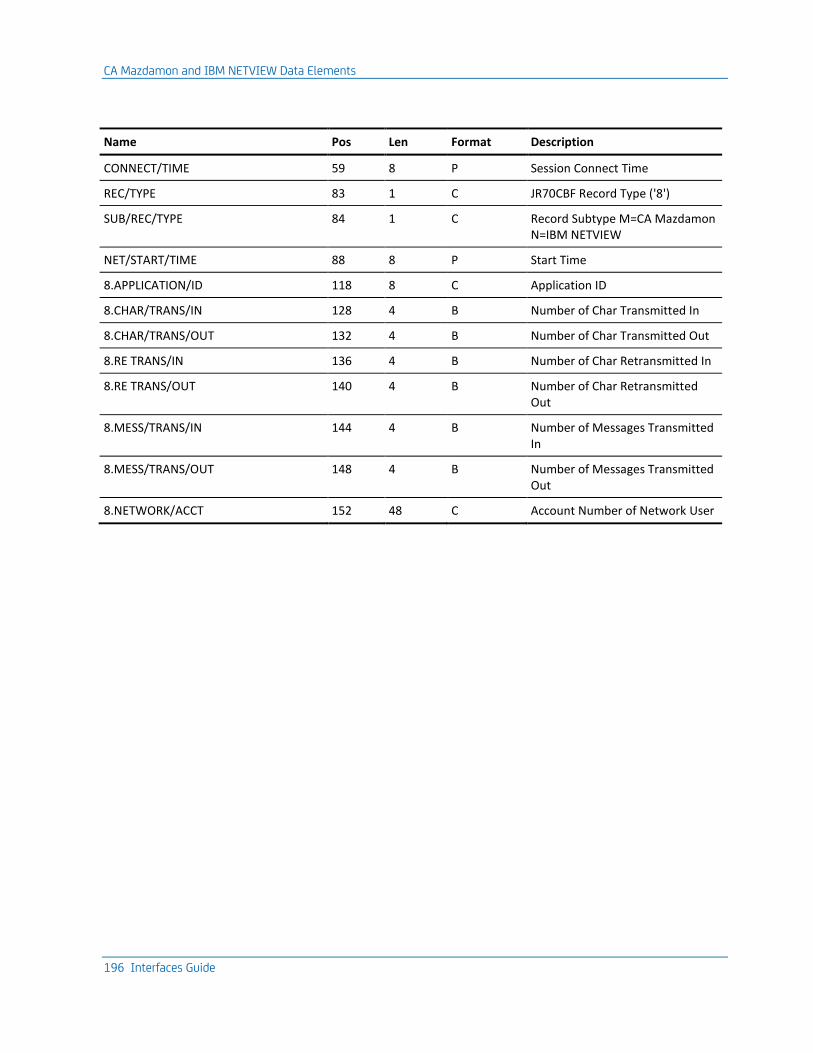
CA Mazdamon and IBM NETVIEW Data Elements
196 Interfaces Guide
Name Pos Len Format Description
CONNECT/TIME 59 8 P Session Connect Time
REC/TYPE 83 1 C JR70CBF Record Type ('8')
SUB/REC/TYPE 84 1 C Record Subtype M=CA Mazdamon N=IBM NETVIEW
NET/START/TIME 88 8 P Start Time
8.APPLICATION/ID 118 8 C Application ID
8.CHAR/TRANS/IN 128 4 B Number of Char Transmitted In
8.CHAR/TRANS/OUT 132 4 B Number of Char Transmitted Out
8.RE TRANS/IN 136 4 B Number of Char Retransmitted In
8.RE TRANS/OUT 140 4 B Number of Char Retransmitted Out
8.MESS/TRANS/IN 144 4 B Number of Messages Transmitted In
8.MESS/TRANS/OUT 148 4 B Number of Messages Transmitted Out
8.NETWORK/ACCT 152 48 C Account Number of Network User

EXTDATA Reports
Chapter 5: The Network Accounting Interface 197
EXTDATA Reports
There are sample CA Earl and CA Easytrieve reports that will process the NETVIEW Interface EXTDATA records.
Note: The EXTDATA record layout is described in the chapter "EXTDATA Reporting" in the User Guide.
OPTION LIST OFF
NOTE ******************************************************************
NOTE * REPORT ID: ERXTN001 *
NOTE * REPORT NAME: NETVIEW SESSION DETAIL REPORT *
NOTE * *
NOTE * DESCRIPTION: THIS REPORT ITEMIZES ALL NETVIEW SESSIONS THAT*
NOTE * APPEAR IN A CA JARS ACCOUNTING FILE.*
NOTE * THE DATA ITEMS REPORTED ON IN THE REPORT ARE *
NOTE * START AND END TIME, THE LINE USE TIME, THE *
NOTE * TERMINAL AND APPLICATION ID, AS WELL AS THE *
NOTE * BYTES TRANSMITTED EITHER WAY. *
NOTE * *
NOTE * RECORD TYPES: MRXTHDR, *
NOTE * MRXTSIEN *
NOTE * *
NOTE * EXTDATA RECORD: SIEN *
NOTE * *
NOTE * MACROS: *
NOTE ******************************************************************
OPTION PRINTER = 132
OPTION PAGE = 60
OPTION PRECISION = ALL
OPTION CPAGE = 60
HISTIN: FILE JARS RECORD=3697
DEF INAREA 1-3697 X
COPY MRXTHDR
COPY MRXTSIEN
COPY JARRAY
COPY DEFDATE1
DEF SDATE (X 8) = NONE 'START' 'DATE'
DEF EDATE (X 8) = NONE 'END' 'DATE'
NOTE ******************************************************************
NOTE * SELECTING FROM HISTORY FILE EXTDATA, SPECIFICALLY SIEN *
NOTE ******************************************************************
!
IF PROCID NOT = ':' OR
EXTTYPE NOT = 'SIEN'
THEN GOTO START
ENDIF
!
SET CAI_DATE = EXTSIEN_START_JDATE

EXTDATA Reports
198 Interfaces Guide
PERFORM DATE_CONVERSION
SET SDATE = CAI_OUTDATE
SET CAI_DATE = EXTSIEN_END_JDATE
PERFORM DATE_CONVERSION
SET EDATE = CAI_OUTDATE
!
DATE_CONVERSION: PROC
NOTE ******************************************************************
NOTE * THIS PROCEDURE CONVERTS A JULIAN DATE TO A GREGORIAN DATE. *
NOTE ******************************************************************
SET CAI_OUTDATE = ' '
GOTO CAI_NODATE (CAI_DAYS = 0)
SET CAI_R1 = 1
SET CAI_NDAYS = CAI_DAYS
SET CAI_DTAB (/2/) = 28
SET C_YEAR (3.0) = (CAI_YEAR / 4)
SET C_YEAR = C_YEAR * 4
IF C_YEAR = CAI_YEAR THEN
SET CAI_DTAB (/2/) = 29
ENDIF
SET CAI_OUTDATE = '00/00/00'
CAI_DATE_LOOP:
IF CAI_NDAYS < 0 THEN GOTO CAI_LOOP_END
ENDIF
IF CAI_NDAYS = 0 THEN GOTO CAI_LOOP_END
ENDIF
IF CAI_R1 > 12 THEN GOTO CAI_LOOP_END
ENDIF
SET CAI_NDAYS = (CAI_NDAYS - CAI_DTAB(/CAI_R1/))
SET CAI_MNTH = CAI_R1
SET CAI_R1 = CAI_R1 + 1
GOTO CAI_DATE_LOOP
CAI_LOOP_END:
SET CAI_OUTDD = (CAI_NDAYS + CAI_DTAB(/CAI_MNTH/))
SET CAI_OUTMM = CAI_MNTH
SET CAI_OUTYY = CAI_YEAR
CAI_NODATE:
ENDPROC
!
NOTE ******************************************************************
NOTE * REPORT PROCESSING SECTION *
NOTE ******************************************************************
!
REPORT 'NETVIEW SESSION DETAIL'
TITLE ' '
TITLE @1 'REPORT ID: ERXTN001' @54 'SYSTEM ID:' SID
TITLE @1 'SOURCE : SMF 39' @54 ' ACCOUNT:' EXTSIEN_ACCOUNTING
TITLE ' '
!
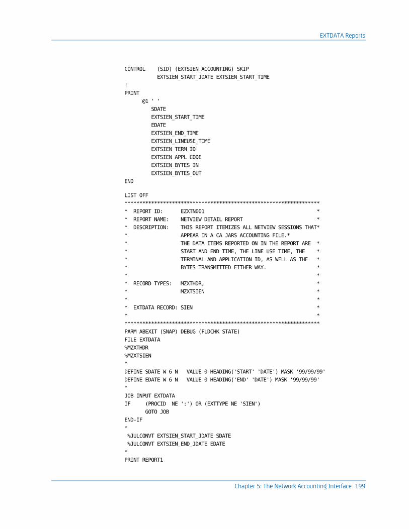
EXTDATA Reports
Chapter 5: The Network Accounting Interface 199
CONTROL (SID) (EXTSIEN_ACCOUNTING) SKIP
EXTSIEN_START_JDATE EXTSIEN_START_TIME
!
@1 ' '
SDATE
EXTSIEN_START_TIME
EDATE
EXTSIEN_END_TIME
EXTSIEN_LINEUSE_TIME
EXTSIEN_TERM_ID
EXTSIEN_APPL_CODE
EXTSIEN_BYTES_IN
EXTSIEN_BYTES_OUT
END
LIST OFF
******************************************************************
* REPORT ID: EZXTN001 *
* REPORT NAME: NETVIEW DETAIL REPORT *
* DESCRIPTION: THIS REPORT ITEMIZES ALL NETVIEW SESSIONS THAT*
* APPEAR IN A CA JARS ACCOUNTING FILE.*
* THE DATA ITEMS REPORTED ON IN THE REPORT ARE *
* START AND END TIME, THE LINE USE TIME, THE *
* TERMINAL AND APPLICATION ID, AS WELL AS THE *
* BYTES TRANSMITTED EITHER WAY. *
* *
* RECORD TYPES: MZXTHDR, *
* MZXTSIEN *
* *
* EXTDATA RECORD: SIEN *
* *
******************************************************************
PARM ABEXIT (SNAP) DEBUG (FLDCHK STATE)
FILE EXTDATA
%MZXTHDR
%MZXTSIEN
*
DEFINE SDATE W 6 N VALUE 0 HEADING('START' 'DATE') MASK '99/99/99'
DEFINE EDATE W 6 N VALUE 0 HEADING('END' 'DATE') MASK '99/99/99'
*
JOB INPUT EXTDATA
IF (PROCID NE ':') OR (EXTTYPE NE 'SIEN')
GOTO JOB
END-IF
*
%JULCONVT EXTSIEN_START_JDATE SDATE
%JULCONVT EXTSIEN_END_JDATE EDATE
*
PRINT REPORT1
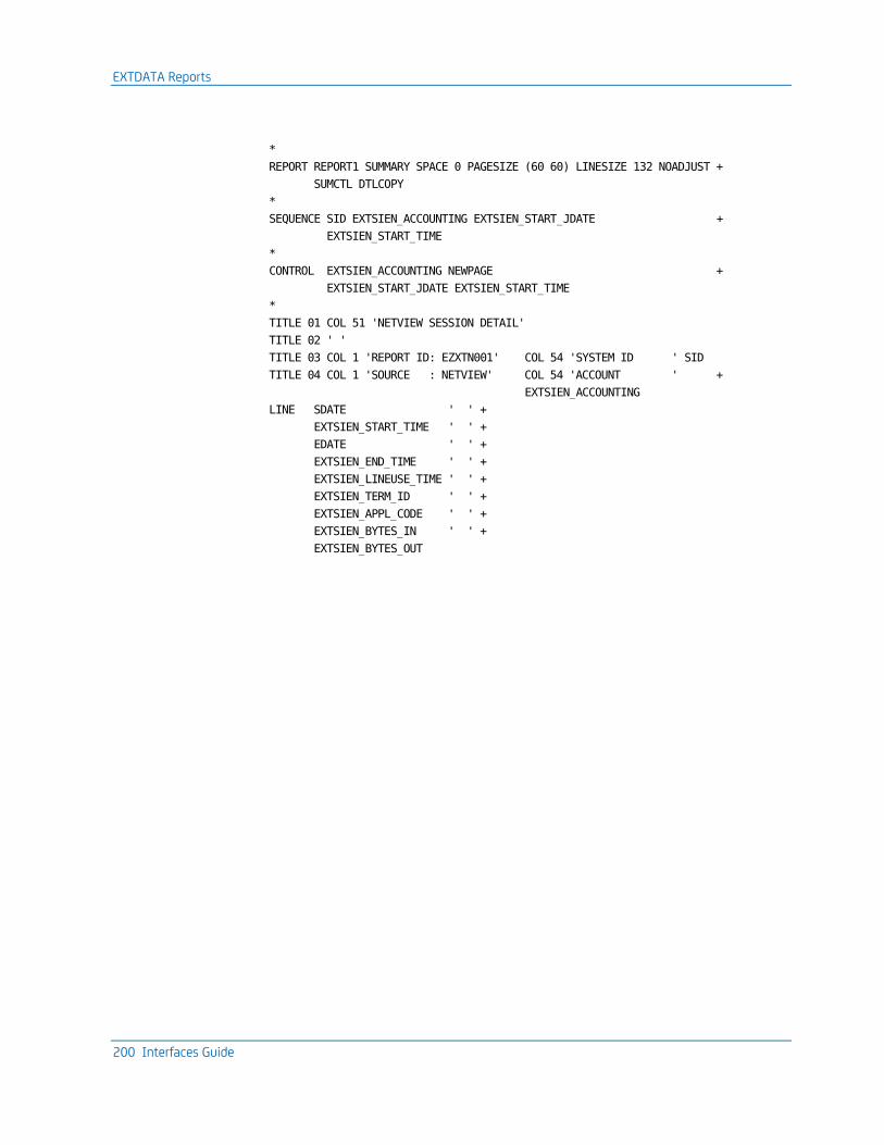
EXTDATA Reports
200 Interfaces Guide
*
REPORT REPORT1 SUMMARY SPACE 0 PAGESIZE (60 60) LINESIZE 132 NOADJUST +
SUMCTL DTLCOPY
*
SEQUENCE SID EXTSIEN_ACCOUNTING EXTSIEN_START_JDATE +
EXTSIEN_START_TIME
*
CONTROL EXTSIEN_ACCOUNTING NEWPAGE +
EXTSIEN_START_JDATE EXTSIEN_START_TIME
*
TITLE 01 COL 51 'NETVIEW SESSION DETAIL'
TITLE 02 ' '
TITLE 03 COL 1 'REPORT ID: EZXTN001' COL 54 'SYSTEM ID ' SID
TITLE 04 COL 1 'SOURCE : NETVIEW' COL 54 'ACCOUNT ' +
EXTSIEN_ACCOUNTING
LINE SDATE ' ' +
EXTSIEN_START_TIME ' ' +
EDATE ' ' +
EXTSIEN_END_TIME ' ' +
EXTSIEN_LINEUSE_TIME ' ' +
EXTSIEN_TERM_ID ' ' +
EXTSIEN_APPL_CODE ' ' +
EXTSIEN_BYTES_IN ' ' +
EXTSIEN_BYTES_OUT

EXTDATA Reports
Chapter 5: The Network Accounting Interface 201
The sample output looks like this:
121/01/04 NETVIEW SESSION DETAIL
REPORT ID: ERXTN001 SYSTEM ID: SCNN
SOURCE : SMF 39 ACCOUNT:
-------------------------------------------------------------------------------------------------------------------------------
START START END END LINE USAGE TERMINAL APPLICATION BYTES BYTE
DATE TIME DATE TIME TIME ID CODE IN OU
-------------------------------------------------------------------------------------------------------------------------------
91/04/01 18:44:50.8900 91/04/01 23:55:01.0200 18610.1200 ________ HOST59 0 0
91/04/01 18:51:27.2500 91/04/01 23:55:03.1200 18215.8600 ________ HOST59 3 41
91/04/01 18:54:02.4400 91/04/01 23:55:06.2600 18063.8100 ________ HOST59 3 41
91/04/01 18:54:02.4400 91/04/01 23:55:06.2600 18063.8100 ________ HOST59 3 41
91/04/01 18:54:04.5400 91/04/01 23:55:07.3100 18062.7700 ________ HOST59 532 59
91/04/01 18:54:10.8300 91/04/01 23:55:09.4100 18058.5700 ________ HOST59 83 44
91/04/01 18:54:13.9800 91/04/01 23:55:12.5500 18058.5700 ________ HOST59 0 0
91/04/01 18:54:13.9800 91/04/01 23:55:12.5500 18058.5700 ________ HOST59 3 41
91/04/01 18:54:17.1200 91/04/01 23:55:13.6000 18056.4700 ________ HOST59 0 0
91/04/01 18:54:18.1700 91/04/01 23:55:15.7000 18057.5200 ________ HOST59 3 41
91/04/01 18:54:19.2200 91/04/01 23:55:16.7500 18057.5200 ________ HOST59 532 59
91/04/01 18:54:22.3700 91/04/01 23:55:18.8500 18056.4700 ________ HOST59 1268 74
91/04/01 18:54:25.5100 91/04/01 23:55:20.9400 18055.4300 ________ HOST59 3 41
91/04/01 18:54:26.5600 91/04/01 23:55:23.0400 18056.4700 ________ HOST59 292 50
91/04/01 18:54:29.7100 91/04/01 23:55:26.1900 18056.4700 ________ HOST59 0 0
91/04/01 18:54:29.7100 91/04/01 23:55:26.1900 18056.4700 ________ HOST59 0 0
91/04/01 18:54:32.8500 91/04/01 23:55:28.2800 18055.4300 ________ HOST59 83 44
91/04/01 18:54:32.8500 91/04/01 23:55:29.3300 18056.4700 ________ HOST59 3 41
91/04/01 18:54:36.0000 91/04/01 23:55:31.4300 18055.4300 ________ HOST59 3 41
91/04/01 18:54:39.1400 91/04/01 23:55:34.5700 18055.4300 ________ HOST59 0 0
91/04/01 18:54:39.1400 91/04/01 23:55:34.5700 18055.4300 ________ HOST59 0 0
91/04/01 18:54:39.1400 91/04/01 23:55:34.5700 18055.4300 ________ HOST59 0 0
91/04/01 18:54:39.1400 91/04/01 23:55:34.5700 18055.4300 ________ HOST59 0 0
91/04/01 18:54:39.1400 91/04/01 23:55:34.5700 18055.4300 ________ HOST59 0 0
91/04/01 18:54:39.1400 91/04/01 23:55:34.5700 18055.4300 ________ HOST59 0 0
91/04/01 18:54:39.1400 91/04/01 23:55:34.5700 18055.4300 ________ HOST59 0 0
91/04/01 18:54:39.1400 91/04/01 23:55:34.5700 18055.4300 ________ HOST59 0 0
91/04/01 18:54:39.1400 91/04/01 23:55:34.5700 18055.4300 ________ HOST59 0 0
91/04/01 18:54:39.1400 91/04/01 23:55:34.5700 18055.4300 ________ HOST59 0 0
91/04/01 18:54:39.1400 91/04/01 23:55:34.5700 18055.4300 ________ HOST59 0 0
91/04/01 18:54:39.1400 91/04/01 23:55:34.5700 18055.4300 ________ HOST59 0 0
91/04/01 18:54:40.1900 91/04/01 23:55:34.5700 18054.3800 ________ HOST59 0 0
91/04/01 18:54:40.1900 91/04/01 23:55:35.6200 18055.4300 ________ HOST59 0 0
91/04/01 18:54:40.1900 91/04/01 23:55:35.6200 18055.4300 ________ HOST59 0 0
91/04/01 18:54:40.1900 91/04/01 23:55:34.5700 18054.3800 ________ HOST59 0 0
91/04/01 18:54:40.1900 91/04/01 23:55:35.6200 18055.4300 ________ HOST59 0 0
91/04/01 18:54:40.1900 91/04/01 23:55:35.6200 18055.4300 ________ HOST59 0 0
91/04/01 18:54:40.1900 91/04/01 23:55:35.6200 18055.4300 ________ HOST59 0 0
91/04/01 18:54:40.1900 91/04/01 23:55:35.6200 18055.4300 ________ HOST59 0 0
91/04/01 18:54:40.1900 91/04/01 23:55:35.6200 18055.4300 ________ HOST59 0 0
91/04/01 18:54:40.1900 91/04/01 23:55:35.6200 18055.4300 ________ HOST59 0 0
91/04/01 18:54:40.1900 91/04/01 23:55:35.6200 18055.4300 ________ HOST59 0 0
91/04/01 18:54:40.1900 91/04/01 23:55:34.5700 18054.3800 ________ HOST59 0 0
91/04/01 18:54:40.1900 91/04/01 23:55:34.5700 18054.3800 ________ HOST59 0 0
91/04/01 18:54:40.1900 91/04/01 23:55:34.5700 18054.3800 ________ HOST59 0 0
91/04/01 18:54:41.2400 91/04/01 23:55:35.6200 18054.3800 ________ HOST59 0 0
91/04/01 18:54:41.2400 91/04/01 23:55:36.6700 18055.4300 ________ HOST59 0 0
91/04/01 18:54:41.2400 91/04/01 23:55:36.6700 18055.4300 ________ HOST59 0 0
91/04/01 18:54:41.2400 91/04/01 23:55:36.6700 18055.4300 ________ HOST59 0 0
91/04/01 18:54:41.2400 91/04/01 23:55:36.6700 18055.4300 ________ HOST59 0 0

Chapter 6: The CA Roscoe Interface 203
Chapter 6: The CA Roscoe Interface
The Interface to Roscoe is distributed as part of the CA JARS (Job Accounting Report System) family of programs. It provides users of the Roscoe software package with the reporting and chargeback capabilities of CA JARS. With this interface, you can use the Report Writer to report on Roscoe data.
This section contains the following topics:
Functional Description (see page 203) Roscoe Journal File (see page 204) Operating Instructions (see page 210) Sample Reports (see page 216) Reporting Considerations (see page 233)
Functional Description
The Interface to CA Roscoe translates CA Roscoe sign-off records to CA JARS level-7 history records. The interface is made up of two programs:
■ MA0000 - Product Executive
■ MA1000 - Record Processor
The input to the interface is a Roscoe journal file or an SMF file with Roscoe user records from which sign-off records are selected. An input control statement is read by the Roscoe Interface program to determine what type of data is being input. The output is a CA JARS level-7 history file for subsequent input to the Report Writer. The Report Writer processes Roscoe summary records in a way similar to that for TSO sessions.
This interface can also be used to generate EXTDATA records. EXTDATA records can be used for reporting with CA EARL and CA Easytrieve. The layout and format of the EXTDATA records are described in the chapter "EXTDATA Reporting" in the User Guide.
In addition, the EXTDATA records can be used in conjunction with CA PMA Chargeback to create billing and chargeback systems for Roscoe resource utilization.

Roscoe Journal File
204 Interfaces Guide
Roscoe Journal File
Roscoe Sign-off Record Layout Pre Roscoe Release 5.5
SMF Header Portion:
Field Name Field Position
Field Length
FMT
Description
SMFFLG 1 1 b SMF header flag byte
SMFRTY 2 1 b SMF record type
SMFTME 3-6 4 b SMF write time
SMFDTE 7-10 4 b SMF write date
SMFSID 11-14 4 a SMF system ID
ROSJOB 15-22 8 a Name of Roscoe job
ROSITIME 23-26 4 p Time of Roscoe start
ROSIDATE 27-30 4 p Date of Roscoe start
Roscoe Sign-off Record Layout (page 1 of 2)
Roscoe Log Portion:
Field Name Field Position
Field Length
FMT
Description
SIDB 1-2 2 b User Session ID
SVTAMID 3-10 8 a VTAM Terminal Name
SAMETH 11-12 2 b Access method
FILLER1 13-20 8 - Filler
SKEY 21-42 22 a User Sign-on Key
SJOBNM 21-28 8 a Job Name
29-42 14 - Filler
STERMTYP 43-44 2 b Terminal Type
FILLER3 45-48 4 - Filler
STERMNUM 49-52 4 b User Terminal ID
SONTIME 53-56 4 b Sign-on Time

Roscoe Journal File
Chapter 6: The CA Roscoe Interface 205
Field Name Field Position
Field Length
FMT
Description
SUSER 57-60 4 b User Command Count
SESTUCPU 61-64 4 b CPU Time (Timer Units)
STERMACC 65-68 4 b Terminal Accesses
SDISKACC 69-72 4 b Disk Accesses
SJOBS 73-74 2 b Jobs Submitted
SRECTYPE 75 1 a Record Type (=C'1')
FILLER4 76 1 - Filler
SOFFTIME 77-80 4 b Sign-off Time
SDATE 81-86 6 a Date (MMDDYY)
FILLER5 87 1 - Filler
SUCB 88-90 3 a UCB Number of Terminal
SROSID 91-94 4 b Roscoe Session ID
FILLER6 95-100 6 - Filler
Roscoe Sign-off Record Layout (page 2 of 2)
Roscoe Record Layout for Roscoe 5.5 and Above
Roscoe Common Portion:
Field Name Field Position
Field Length
FMT
Description
1-14 14 b SMF Header
SRJOBNM 15-22 8 a Roscoe Job Name
SRRITME 23-26 4 b Roscoe INIT Time (HHMMSSTH)
SRRIDTE 27-30 4 p Roscoe INIT Date (00YYDDDF)
SRUSKEY 31-52 22 a User Sign-on Key
SRUFKEY 53-74 22 a User Formal Key
SRUAF 75-94 20 a User Accounting Field
SRUSONT 95-98 4 b User Sign-on Time
SRUSOND 99-102 4 p User Sign-on Date (00YYDDDF)

Roscoe Journal File
206 Interfaces Guide
Field Name Field Position
Field Length
FMT
Description
SRTYPE 103-103 1 a Record Type
x'10' Sign-on Record
x'20' Sign-off Record
x'30' RTM Record
x'34' Roscoe Statistics Record
x'50' LIB STATS Record
x'60' Monitor Record
x'70' Data Set Facility
x'90' VPE Record
x'F0' AWS Record
x'F4' Shutdown Record
SRMONNM 104-106 3 a Monitor Name
SRMONTYP 107-107 1 b Monitor Type
SRFLAG 108-108 1 b Flag
SRRESV1 109-112 4 b Reserved
SRRESV2 113-116 4 b Reserved
SRRESV3 117-120 4 b Reserved
Roscoe Record Layout (page 1 of 3)
Sign-On Record:
Field Name Field Position
Field Length
FMT
Description
S10AMETH 121-121 1 b Access Method
S10VTAM 122-129 8 c Terminal Name
S10UNVPW 130-130 1 c UNIVERSE Password
Roscoe Record Layout (page 2 of 3)
Sign-Off Record:
Field Name Field Position
Field Length
FMT
Description
S20CPU 121-124 4 b CPU Used (Timer Units)
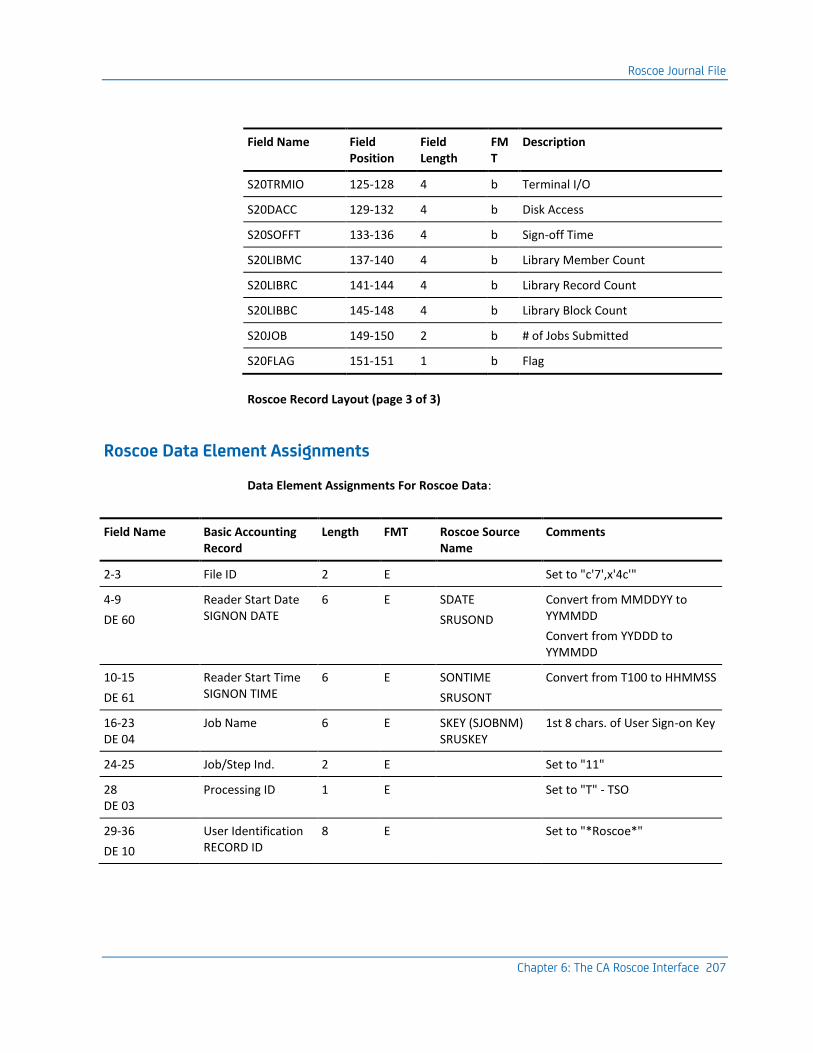
Roscoe Journal File
Chapter 6: The CA Roscoe Interface 207
Field Name Field Position
Field Length
FMT
Description
S20TRMIO 125-128 4 b Terminal I/O
S20DACC 129-132 4 b Disk Access
S20SOFFT 133-136 4 b Sign-off Time
S20LIBMC 137-140 4 b Library Member Count
S20LIBRC 141-144 4 b Library Record Count
S20LIBBC 145-148 4 b Library Block Count
S20JOB 149-150 2 b # of Jobs Submitted
S20FLAG 151-151 1 b Flag
Roscoe Record Layout (page 3 of 3)
Roscoe Data Element Assignments
Data Element Assignments For Roscoe Data:
Field Name Basic Accounting Record
Length FMT Roscoe Source Name
Comments
2-3 File ID 2 E Set to "c'7',x'4c'"
4-9
DE 60
Reader Start Date SIGNON DATE
6 E SDATE
SRUSOND
Convert from MMDDYY to YYMMDD
Convert from YYDDD to YYMMDD
10-15
DE 61
Reader Start Time SIGNON TIME
6 E SONTIME
SRUSONT
Convert from T100 to HHMMSS
16-23 DE 04
Job Name 6 E SKEY (SJOBNM) SRUSKEY
1st 8 chars. of User Sign-on Key
24-25 Job/Step Ind. 2 E Set to "11"
28 DE 03
Processing ID 1 E Set to "T" - TSO
29-36
DE 10
User Identification RECORD ID
8 E Set to "*Roscoe*"

Roscoe Journal File
208 Interfaces Guide
Field Name Basic Accounting Record
Length FMT Roscoe Source Name
Comments
37-42
DE 12
Start Time 6 E SONTIME SRUSONT ROSITIME SRRITIME
Convert from T100 to HHMMSS
Roscoe Start Time (SMF ONLY)
43-48
DE 06
Run Date 6 E SDATE SRUSOND ROSIDATE SRRIDTE
Convert from MMDDYY to YYMMDD
Roscoe Start Date (SMF ONLY)
49-50 DE 07
Job Class 2 E Set to "V"
51-56 DE 13
Stop Time SIGNOFF TIME
6 E SOFFTIME S20OFFT
Convert from T100 to HHMMSS
57-78
DE 58
Programmer Name USER SIGNON KEY
22 E SKEY
SRUSKEY
User Sign-on Key
99-106 DE 11
Step Name TERMINAL NAME
8 E SVTAMID S10VTAM
VTAM Terminal Name
107-114
DE 05
Program/Phase Name Roscoe JOB NAME
8 E ROSJOB
SRJOBNM
Roscoe Job Name (SMF ONLY)
126-130 DE 14
Job Number SESSION ID
5 E SIDB User Session ID (1)
171-176 DE 25
Elapsed Time 6 P SONTIME- SOFFTIME SRUSONT- SROSOFFT
Elapsed Time (Hours) DEC 5
177-182 DE 26
CPU Time 6 P SESTUCPU SCPU20
CPU Time in Hundredths of a Second
241-247 DE 38
Disk I/O Count DISK ACCESSES
7 P SDISKACC S20DACC
Disk Accesses
248-254 DE 39
Other I/O Count TERMINAL ACCESSES
7 P STERMACC S20TRMIO
Terminal Accesses
255-261 DE 40
Total I/O Count TOTAL ACCESSES
7 P SDISKACC + STERMACC S20TRMIO + S20DACC
Total of Disk and Terminal Accesses

Roscoe Journal File
Chapter 6: The CA Roscoe Interface 209
Field Name Basic Accounting Record
Length FMT Roscoe Source Name
Comments
262-265 DE 78
I/O Index 4 P (Total EXCP's * 10 Million)/(CPU Time * 3600)
301-308
DE A0
Input Device Name TERMINAL ID
8 E STERMNUM User Terminal ID (1)
365-368 DE A5
TPUTs JOBS SUBMITTED
4 P SJOBS S20JOB
Jobs Submitted
373-378 DE A7
Active Time 6 P Elapsed Time in Hours DEC 5
379-384 DE B0
Connect Time 6 P Elapsed Time in Hours DEC 5
391-396 DE C1
Resident Time 6 p Elapsed Time in Hours DEC 5
403-408 DE C7
CPU Time (TCB) 6 P SESTUCPU S20CPU
See CPU time
429-431
DE B6
Input Route Code TERMINAL NUMBER
3 E SUCB UCB # of Terminal (1)
432-434 DE B7
Print Route Code TERMINAL TYPE
3 E STERMTYPE Terminal Type (1)
437 DE D5
Day-of-week Indicator
1 E SDATE SRUSOND
Day-of-Week Calculation
446-453
DE E4
Output Device Name Roscoe ID
8 E SROSID SRJOBNM
Roscoe Session ID
487-502 DE F2
ACCOMF Field2 USER FORMAL KEY
16 e SRUFKEY User Formal Key (5)
503-518 DE F3
Account Field3 USER ACCOUNT FIELD
16 e SRUAF User Account Key (5)
535-539 DE F5
User Count Field 5 p SUSER User Count field (1) divided by 2
545-550 Reserved 6 E Set to "YNNNNN"
(1) NOT available for Roscoe 5.5 or above.
(5) Only available for Roscoe 5.5 or above.

Operating Instructions
210 Interfaces Guide
Operating Instructions
The region size suggested to execute the interface is approximately 4096K. The interface to Roscoe reads a required input control statement to determine the type of input. The control statement is read in through CAIJRIN in the following format:
Control Statement Layout - Roscoe Release 5.4 and earlier:
Field Name Field Position
Field Length
FMT Description
Statement Type 1-5 5 a 'Input'
6-9 5 a Filler
Input Type 10-12 3 a 'LOG' - Roscoe Journal File 'SMF' - SMF input
SMF Type 13-15 3 /n blank - If input type = LOG (Roscoe Journal File) 'nnn' - If input type = SMF, with 'nnn' the user record type for Roscoe records
Control Statement Layout - Roscoe Release 5.5 and later:
Field Name Field Position
Field Length
FMT Description
Statement Type 1-5 5 a 'Input'
6-9 4 - Filler
Input Type 10-12 3 a '5.5'
SMF Type 13-15 3 /n blank - For Roscoe Journal File 'nnn' - For SMF input, with 'nnn' the user record type for Roscoe records.
The interface requires several interrelated files to execute. The following list describes these data sets and their functions:
CAIJFPR
The CAIJFPR statement describes the SYSOUT data set for generated display messages.
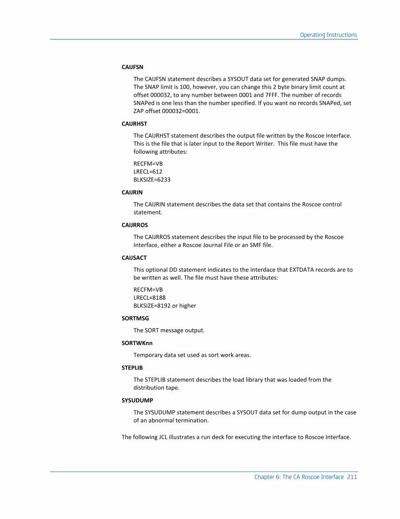
Operating Instructions
Chapter 6: The CA Roscoe Interface 211
CAIJFSN
The CAIJFSN statement describes a SYSOUT data set for generated SNAP dumps. The SNAP limit is 100, however, you can change this 2 byte binary limit count at offset 000032, to any number between 0001 and 7FFF. The number of records SNAPed is one less than the number specified. If you want no records SNAPed, set ZAP offset 000032=0001.
CAIJRHST
The CAIJRHST statement describes the output file written by the Roscoe Interface. This is the file that is later input to the Report Writer. This file must have the following attributes:
RECFM=VB LRECL=612 BLKSIZE=6233
CAIJRIN
The CAIJRIN statement describes the data set that contains the Roscoe control statement.
CAIJRROS
The CAIJRROS statement describes the input file to be processed by the Roscoe Interface, either a Roscoe Journal File or an SMF file.
CAIJSACT
This optional DD statement indicates to the interdace that EXTDATA records are to be written as well. The file must have these attributes:
RECFM=VB LRECL=8188 BLKSIZE=8192 or higher
SORTMSG
The SORT message output.
SORTWKnn
Temporary data set used as sort work areas.
STEPLIB
The STEPLIB statement describes the load library that was loaded from the distribution tape.
SYSUDUMP
The SYSUDUMP statement describes a SYSOUT data set for dump output in the case of an abnormal termination.
The following JCL illustrates a run deck for executing the interface to Roscoe Interface.

Operating Instructions
212 Interfaces Guide
Sample JCL for Interface to Roscoe
//ROSRUN JOB ,'RUN Roscoe INTERFACE',CLASS=A,MSGCLASS=M
//*
//* DOC: THIS JOB EXECUTES THE Roscoe INTERFACE PROGRAM.
//*
//* YOU MUST CHANGE THE VOLUME AND UNIT DESIGNATORS IN THIS
//* JCL TO DESCRIBE THE ACTUAL VOLUMES ON WHICH YOUR DATA
//* SETS RESIDE. YOU MUST ALSO CHANGE THE RESPECTIVE
//* DATA SET NAMES.
//*
//* THIS JCL REFERS TO DATA SET NAME CA.JARS.PRODLIB ON
//* THE STEPLIB DD. THIS NAME MUST MATCH THE ONE WITH WHICH
//* YOU LOADED THE LOAD LIBRARY FROM THE DISTRIBUTION TAPE.
//*
//* CAIJFPR DD Roscoe OUTPUT
//* CAIJFSN DD SNAPED RECORDS
//* CAIJRIN DD CONTROL CARD INPUT
//* (INPUT CONTROL CARD REQUIRED)
//* CAIJRROS DD Roscoe OR SMF INPUT DATA
//* CAIJRHST DD JARS HISTORY FILE
//* SORTWKnn DD TEMP SORT WORK AREA
//*
//JSSS01 EXEC PGM=JSI,PARM='XXXX0080,JSMA0000'
//STEPLIB DD DSN=CAI.CAJRLOAD,DISP=SHR
//*
//CAIJFPR DD SYSOUT=*
//CAIJFSN DD SYSOUT=*
//SORTWK01 DD UNIT=SYSDA, SPACE=(CYL,(3))
//SORTWK02 DD UNIT=SYSDA, SPACE=(CYL,(3))
//SORTWK03 DD UNIT=SYSDN, SPACE=(CYL,(3))
//SORTMSG DD SYSOUT=*
//*
//CAIJRIN DD *
INPUT SMF248
OR
INPUT LOG
OR
INPUT 5.5248
OR
INPUT 5.5
/*
//CAIJRROS DD DSN=SMF.DAILY,DISP=SHR,UNIT=3350,
// DCB=(RECFM=VBS,LRECL=32759,BLKSIZE=4096)
//CAIJRHST DD DSN=JARS.Roscoe.HISTORY,DISP=(NEW,CATLG,DELETE),
// UNIT=3350,VOL=SER=WORK01,SPACE=(TRK,(5,5)),
// DCB=(RECFM=VB,LRECL=612,BLKSIZE=6233),SPACE=(TRK,(5,5))
//CAIJSACT DD DSN=CAI.ROSCOE.EXTDATA,
// DISP=(NEW,CATLG,DELETE),
// UNIT=uuuu,

Operating Instructions
Chapter 6: The CA Roscoe Interface 213
// SPACE=(CYL,(pp,ss),RLSE),
// DCB=(RECFM=VB,LRECL=8188,BLKSIZE=bbbb),
// VOL=SER=vvvvvv
//*
//

Operating Instructions
214 Interfaces Guide
The following JCL illustrates a run deck for producing a Roscoe Session Analysis Report using the Report Writer. This JCL is included as member ROSJARS1 in CAJRJCL.
Sample JCL for Interface to Roscoe Session Analysis Report
//JARS1 JOB (CAI,GXB),CMSGXB,CLASS=A,MSGCLASS=M
//*
//* DOC: THIS JOB EXECUTES THE CA JARS REPORT PROGRAM TO
//* PRODUCE A Roscoe SESSION ANALYSIS REPORT, USING
//* A Roscoe HISTORY FILE AS INPUT.
//*
//*
//JARS EXEC PGM=JSIMAIN
//STEPLIB DD DSN=CAI.CAJRLOAD,DISP=SHR
//*
//CAIJSPRT DD SYSOUT=*
//SYSUDUMP DD SYSOUT=*
//CAIJSNAP DD SYSOUT=*
//SORTWK01 DD UNIT=SYSDA,
// SPACE=(CYL,(5))
//SORTWK02 DD UNIT=SYSDA,
// SPACE=(CYL,(5))
//SORTWK03 DD UNIT=SYSDA,
// SPACE=(CYL,(5))
//SORTWK04 DD UNIT=SYSDA,
// SPACE=(CYL,(5))
//SORTWK05 DD UNIT=SYSDA,
// SPACE=(CYL,(5))
//SORTWK06 DD UNIT=SYSDA,
// SPACE=(CYL,(5))
//CAIJSCT2 DD UNIT=SYSDA,DISP=(,DELETE,DELETE),
// SPACE=(TRK,(10,1))
//CAIJSCT1 DD UNIT=SYSDA,DISP=(,DELETE,DELETE),
// SPACE=(TRK,(10,1))
//CAIJSACT DD UNIT=SYSDA,DISP=(,DELETE,DELETE),
// SPACE=(CYL,(10,5))
//*
//CAIJRHST DD DSN=JARS.Roscoe.HISTORY,DISP=(OLD,KEEP),
// UNIT=3350,VOL=SER=WORK01
//*
//*
//CAIJSCIN DD *
CONFIG OTHE01F
SELECT 1 B
BHEADER R O S C O E S E S S I O N A N A L Y S I S
BSORT 05722A2 1
BDISPLAY MA0582603613132B02261391382A53113B6
/*
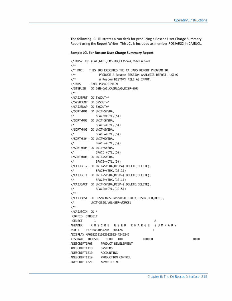
Operating Instructions
Chapter 6: The CA Roscoe Interface 215
The following JCL illustrates a run deck for producing a Roscoe User Charge Summary Report using the Report Writer. This JCL is included as member ROSJARS2 in CAJRJCL.
Sample JCL For Roscoe User Charge Summary Report
//JARS2 JOB (CAI,GXB),CMSGXB,CLASS=A,MSGCLASS=M
//*
//* DOC: THIS JOB EXECUTES THE CA JARS REPORT PROGRAM TO
//* PRODUCE A Roscoe SESSION ANALYSIS REPORT, USING
//* A Roscoe HISTORY FILE AS INPUT.
//JARS EXEC PGM=JSIMAIN
//STEPLIB DD DSN=CAI.CAJRLOAD,DISP=SHR
//*
//CAIJSPRT DD SYSOUT=*
//SYSUDUMP DD SYSOUT=*
//CAIJSNAP DD SYSOUT=*
//SORTWK01 DD UNIT=SYSDA,
// SPACE=(CYL,(5))
//SORTWK02 DD UNIT=SYSDA,
// SPACE=(CYL,(5))
//SORTWK03 DD UNIT=SYSDA,
// SPACE=(CYL,(5))
//SORTWK04 DD UNIT=SYSDA,
// SPACE=(CYL,(5))
//SORTWK05 DD UNIT=SYSDA,
// SPACE=(CYL,(5))
//SORTWK06 DD UNIT=SYSDA,
// SPACE=(CYL,(5))
//CAIJSCT2 DD UNIT=SYSDA,DISP=(,DELETE,DELETE),
// SPACE=(TRK,(10,1))
//CAIJSCT1 DD UNIT=SYSDA,DISP=(,DELETE,DELETE),
// SPACE=(TRK,(10,1))
//CAIJSACT DD UNIT=SYSDA,DISP=(,DELETE,DELETE),
// SPACE=(CYL,(10,5))
//*
//CAIJSHST DD DSN=JARS.Roscoe.HISTORY,DISP=(OLD,KEEP),
// UNIT=3350,VOL=SER=WORK01
//*
//CAIJSCIN DD *
CONFIG OTHE01F
SELECT 1 A
AHEADER R O S C O E U S E R C H A R G E S U M M A R Y
ASORT 05703A3105720A 00412A 1
ADISPLAY MA0022581602612B3244245246
ATSORATE 1000500 1000 100 100100 0100
ADESCRIPT1ROS PRODUCT DEVELEPMENT
ADESCRIPT1110 SYSTEMS
ADESCRIPT1210 ACCOUNTING
ADESCRIPT1219 PRODUCTION CONTROL
ADESCRIPT1221 ADVERTISING

Sample Reports
216 Interfaces Guide
ADESCRIPT1222 SALES - EAST
ADESCRIPT1223 SALES - CENTRAL
ADESCRIPT1227 SALES - WEST
ADESCRIPT1231 FINANCE
/*
Sample Reports
Roscoe Interface Reports
The Roscoe Interface reports are produced from the execution of the Interface to Roscoe. Two reports are produced:
■ Roscoe Interface Listing
■ Termination Report
Samples of these reports are shown on the following page. These reports were obtained by executing member ROSRUN in the CA JARS source library.
Roscoe Interface Listing:
CA JARS r12 R O S C O E I N T E R F A C E L I S T I N G PAGE 1
Resource Accounting SP0 17 AUG 1998 15
CAJR010I LOG INPUT FILE PROCESSED.
015D38 0000 00000000 00000000 00000000 00000000 00000000 40404040 40404040 40404040 *.................... *
015D58 0020 40404040 40404040 40400000 00000000 00000000 00000000 F0F5F2F8 F8F40000 * ..............052884..*
015D78 0040 00000000 00000000 00000000 0082CE53 F0F5F2F8 F8F40000 000000AF 4FF90000 *................052884......|9..*
015D98 0060 00000000 *....*
CAJR005W RECORD SNAPPED. REASON CODE C .
----------------------------------------------------------------------------------------------------------------------------------
CAJR011I 149 Roscoe TYPE 1 RECORDS READ.
CAJR011I 2746 Roscoe TYPE 8 RECORDS READ.
CAJR011I 1 Roscoe TYPE 9 RECORDS READ.
CAJR012I 1 UNKNOWN RECORDS READ.
CAJR014I 2897 TOTAL RECORDS READ.
CAJR015I 0 DUPLICATE Roscoe RECORDS REJECTED.
CAJR016I 0 RECORDS REJECTED FOR INVALID DATA.
CAJR017I 149 JARS V4 HISTORY RECORDS WRITTEN.
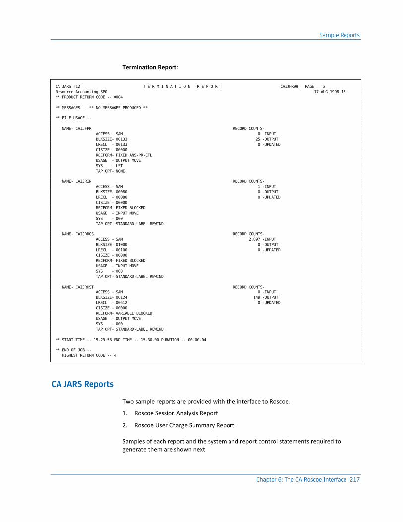
Sample Reports
Chapter 6: The CA Roscoe Interface 217
Termination Report:
CA JARS r12 T E R M I N A T I O N R E P O R T CAIJFR99 PAGE 2
Resource Accounting SP0 17 AUG 1998 15
** PRODUCT RETURN CODE -- 0004
** MESSAGES -- ** NO MESSAGES PRODUCED **
** FILE USAGE --
NAME- CAIJFPR RECORD COUNTS-
ACCESS - SAM 0 -INPUT
BLKSIZE- 00133 25 -OUTPUT
LRECL - 00133 0 -UPDATED
CISIZE - 00000
RECFORM- FIXED ANS-PR-CTL
USAGE - OUTPUT MOVE
SYS - LST
TAP.OPT- NONE
NAME- CAIJRIN RECORD COUNTS-
ACCESS - SAM 1 -INPUT
BLKSIZE- 00080 0 -OUTPUT
LRECL - 00080 0 -UPDATED
CISIZE - 00000
RECFORM- FIXED BLOCKED
USAGE - INPUT MOVE
SYS - 000
TAP.OPT- STANDARD-LABEL REWIND
NAME- CAIJRROS RECORD COUNTS-
ACCESS - SAM 2,897 -INPUT
BLKSIZE- 01000 0 -OUTPUT
LRECL - 00100 0 -UPDATED
CISIZE - 00000
RECFORM- FIXED BLOCKED
USAGE - INPUT MOVE
SYS - 000
TAP.OPT- STANDARD-LABEL REWIND
NAME- CAIJRHST RECORD COUNTS-
ACCESS - SAM 0 -INPUT
BLKSIZE- 06124 149 -OUTPUT
LRECL - 00612 0 -UPDATED
CISIZE - 00000
RECFORM- VARIABLE BLOCKED
USAGE - OUTPUT MOVE
SYS - 000
TAP.OPT- STANDARD-LABEL REWIND
** START TIME -- 15.29.56 END TIME -- 15.30.00 DURATION -- 00.00.04
** END OF JOB --
HIGHEST RETURN CODE -- 4
CA JARS Reports
Two sample reports are provided with the interface to Roscoe.
1. Roscoe Session Analysis Report
2. Roscoe User Charge Summary Report
Samples of each report and the system and report control statements required to generate them are shown next.

Sample Reports
218 Interfaces Guide
Roscoe Session Analysis Report
The sample Roscoe Session Analysis report shown on the following pages was obtained by executing member ROSJARS1 in CAJRJCL. The following system control statements were used.
System Control Statements
1...5...10...15...20...25...30...35...40...45...50...55...60...65 .80
CONFIG OTHE01F
SELECT 1 B
These Report Writer control statements were used to produce the report.
Report Control Statements
1...5...10...15...20...25...30...35...40...45...50...55...60...65 .80
CONFIG OTHE01F
SELECT 1 B
BHEADER R O S C O E S E S S I O N A N A L Y S I S
BSORT 05722A2 1
BDISPLAY MA0582603613132B02261391382A53113B6
1...5...10...15...20...25...30...35...40...45...50...55...60...65 .80

Sample Reports
Chapter 6: The CA Roscoe Interface 219
Here is the sample report (5 pages).
Roscoe Session Analysis Report (page 1 of 5):
R O S C O E S E S S I O N A N A L Y S I S
BEGIN DATE - 07/28/94 RUN DATE - 08/17/94
END DATE - 07/28/94 PAGE 1
SIGNON SIGNON SIGNOFF CONNECT CPU TERMINAL DISK JOBS TERMINAL TRM
USER SIGNON KEY DATE TIME TIME TIME TIME ACCESSES ACCESSES SUBMITTED NAME NUM
ROS.RM.PUBLIC 94/07/28 07:54:12 07:55:42 .02496 .00038 28 149 1 D72L483 VTA
ROS.RM.PUBLIC 94/07/28 10:32:21 10:32:35 .00379 .00018 10 32 0 D72L483 VTA
ROS.RM.PUBLIC 94/07/28 10:43:21 10:44:04 .01198 .00020 18 37 0 D72L483 VTA
ROS.RM.PUBLIC 94/07/28 11:39:45 11:41:43 .03275 .00049 62 126 1 D72L483 VTA
ROS.RM.PUBLIC 94/07/28 15:47:53 15:49:12 .02183 .00054 44 238 1 D72L481 VTA
ROS.RM.PUBLIC 94/07/28 15:49:45 15:50:04 .00526 .00024 26 42 0 D72L481 VTA
.10057 .00203 188 624 3
11012JVDBROEK 94/07/28 16:42:10 16:47:09 .08326 .00050 26 149 1 D72L483 VTA
.08326 .00050 26 149 1
21021JVSTEEN 94/07/28 09:16:08 09:16:13 .00133 .00014 4 30 0 D72L491 VTA
21021JVSTEEN 94/07/28 09:16:17 09:24:44 .14096 .00083 116 235 0 D72L491 VTA
21021JVSTEEN 94/07/28 09:33:22 10:19:49 .77415 .00477 550 919 7 D72L491 VTA
21021JVSTEEN 94/07/28 10:20:22 10:29:33 .15279 .00101 126 145 0 D72L491 VTA
21021JVSTEEN 94/07/28 12:31:21 12:39:07 .12933 .00034 32 99 0 D72L461 VTA
21021JVSTEEN 94/07/28 12:42:02 12:56:16 .23721 .00181 128 600 0 D72L461 VTA
21021JVSTEEN 94/07/28 12:56:28 12:57:57 .02488 .00056 38 186 0 D72L461 VTA
21021JVSTEEN 94/07/28 13:26:45 13:30:09 .05661 .00021 24 41 0 D72L461 VTA
21021JVSTEEN 94/07/28 13:35:43 13:49:07 .22341 .00043 48 135 0 D72L461 VTA
21021JVSTEEN 94/07/28 13:49:12 14:02:50 .22744 .00060 64 148 0 D72L461 VTA
21021JVSTEEN 94/07/28 16:22:59 16:24:35 .02670 .00030 18 90 0 D72L466 VTA
21021JVSTEEN 94/07/28 17:32:48 17:38:20 .09207 .00061 74 121 1 D72L461 VTA
21021JVSTEEN 94/07/28 17:57:32 17:58:32 .01690 .00030 20 76 1 D72L461 VTA
2.10378 .01191 1,242 2,825 9
21022LVSTEEN 94/07/28 09:51:22 09:57:45 .10648 .00045 86 67 0 D72L480 VTA
21022LVSTEEN 94/07/28 13:19:20 13:26:12 .11449 .00028 48 41 0 D72L461 VTA
21022LVSTEEN 94/07/28 13:32:13 13:35:39 .05723 .00015 6 32 0 D72L461 VTA
.27820 .00088 140 140 0
21026EBERENS 94/07/28 11:55:59 12:04:01 .13383 .00031 32 64 0 D72L481 VTA
21026EBERENS 94/07/28 12:30:01 12:35:13 .08656 .00097 154 235 1 D72L481 VTA
21026EBERENS 94/07/28 12:44:59 12:49:01 .06729 .00021 12 39 0 D72L481 VTA
21026EBERENS 94/07/28 17:19:06 17:43:15 .40275 .00071 92 193 2 D72L483 VTA
.69043 .00220 290 531 3
21027JRUTTEN 94/07/28 09:16:35 11:36:23 2.32997 .01202 938 6,943 0 D72L461 VTA
21027JRUTTEN 94/07/28 11:36:28 11:36:42 .00378 .00016 8 32 0 D72L461 VTA
21027JRUTTEN 94/07/28 11:36:49 12:31:14 .90688 .00608 312 3,292 1 D72L461 VTA
21027JRUTTEN 94/07/28 12:39:14 12:41:54 .04443 .00072 40 174 0 D72L461 VTA
21027JRUTTEN 94/07/28 12:58:03 12:59:56 .03137 .00054 30 167 1 D72L461 VTA
21027JRUTTEN 94/07/28 16:33:21 16:51:30 .30241 .00658 532 2,872 3 D72L461 VTA
21027JRUTTEN 94/07/28 16:55:51 16:59:06 .05427 .00024 12 39 0 D72L461 VTA
21027JRUTTEN 94/07/28 17:06:38 17:32:42 .43438 .00134 74 478 0 D72L461 VTA
4.10749 .02768 1,946 13,997 5

Sample Reports
220 Interfaces Guide
Roscoe Session Analysis Report (page 2 of 5):
R O S C O E S E S S I O N A N A L Y S I S
BEGIN DATE - 07/28/94 RUN DATE - 08/17/94
END DATE - 07/28/94 PAGE 2
SIGNON SIGNON SIGNOFF CONNECT CPU TERMINAL DISK JOBS TERMINAL TRM
USER SIGNON KEY DATE TIME TIME TIME TIME ACCESSES ACCESSES SUBMITTED NAME NUM
21031JPIJNENBORG 94/07/28 10:47:31 13:16:52 2.48895 .00917 1,036 4,650 11 D72L491 VTA
21031JPIJNENBORG 94/07/28 13:43:16 13:43:31 .00423 .00015 6 32 0 D72L491 VTA
2.49318 .00932 1,042 4,682 11
21910ROSPROC 94/07/28 07:55:47 08:01:29 .09503 .00086 94 380 1 D72L483 VTA
.09503 .00086 94 380 1
22112HABBINK 94/07/28 10:12:20 10:37:21 .41693 .00457 396 1,886 5 D72L460 VTA
22112HABBINK 94/07/28 10:51:12 10:51:16 .00098 .00006 4 20 0 D72L460 VTA
22112HABBINK 94/07/28 10:51:24 11:35:53 .74147 .00039 68 56 0 D72L460 VTA
22112HABBINK 94/07/28 13:16:49 14:34:28 1.29422 .00543 340 1,890 2 D72L460 VTA
22112HABBINK 94/07/28 14:47:03 16:51:51 2.08000 .00359 718 581 4 D72L460 VTA
4.53360 .01404 1,526 4,433 11
22123FVLOON 94/07/28 09:01:40 09:02:12 .00884 .00020 24 33 0 D72L465 VTA
22123FVLOON 94/07/28 09:10:58 09:32:02 .35115 .00064 118 184 0 D72L465 VTA
22123FVLOON 94/07/28 12:38:07 12:42:05 .06606 .00094 174 442 0 D72L465 VTA
.42605 .00178 316 659 0
22124HCOUWENBERG 94/07/28 14:36:16 14:41:15 .08288 .00073 94 223 0 D72L465 VTA
22124HCOUWENBERG 94/07/28 15:52:24 15:52:43 .00541 .00018 16 41 0 D72L465 VTA
.08829 .00091 110 264 0
22125RVKAPPEL 94/07/28 15:11:35 15:12:54 .02185 .00031 14 50 0 D72L465 VTA
.02185 .00031 14 50 0
22129ALGEMEENSP400 94/07/28 16:31:23 16:32:13 .01383 .00033 54 58 0 D72L465 VTA
.01383 .00033 54 58 0
22201HKUYPERS 94/07/28 12:04:23 12:09:57 .09276 .00162 120 294 0 D72L494 VTA
22201HKUYPERS 94/07/28 13:13:34 13:18:45 .08647 .00111 80 350 0 D72L467 VTA
.17923 .00273 200 644 0
22212MVDUUREN 94/07/28 08:59:38 09:03:60 .07271 .00216 114 734 1 D72L466 VTA
22212MVDUUREN 94/07/28 10:52:02 11:32:03 .66690 .00611 528 1,700 2 D72L466 VTA
22212MVDUUREN 94/07/28 13:35:31 13:35:35 .00114 .00015 4 29 0 D72L466 VTA
22212MVDUUREN 94/07/28 13:35:38 14:20:43 .75163 .01998 1,268 7,957 3 D72L466 VTA
22212MVDUUREN 94/07/28 14:27:05 14:27:43 .01064 .00036 26 100 0 D72L494 VTA
22212MVDUUREN 94/07/28 16:24:54 16:25:47 .01462 .00033 14 90 0 D72L466 VTA
22212MVDUUREN 94/07/28 16:26:54 16:27:23 .00804 .00031 18 55 0 D72L466 VTA
22212MVDUUREN 94/07/28 16:28:42 16:30:05 .02315 .00029 18 66 0 D72L466 VTA
22212MVDUUREN 94/07/28 16:30:58 16:31:02 .00108 .00014 4 29 0 D72L466 VTA
22212MVDUUREN 94/07/28 16:31:05 17:10:10 .65147 .01957 628 10,111 3 D72L466 VTA

Sample Reports
Chapter 6: The CA Roscoe Interface 221
Roscoe Session Analysis Report (page 3 of 5):
R O S C O E S E S S I O N A N A L Y S I S
BEGIN DATE - 07/28/94 RUN DATE - 08/17/94
END DATE - 07/28/94 PAGE 3
SIGNON SIGNON SIGNOFF CONNECT CPU TERMINAL DISK JOBS TERMINAL TRM
USER SIGNON KEY DATE TIME TIME TIME TIME ACCESSES ACCESSES SUBMITTED NAME NUM
2.20138 .04940 2,622 20,871 9
22213WSMEEKENS 94/07/28 10:10:27 10:31:05 .34387 .00269 194 1,320 0 D72L466 VTA
22213WSMEEKENS 94/07/28 10:42:27 10:42:31 .00124 .00014 4 29 0 D72L466 VTA
22213WSMEEKENS 94/07/28 10:42:35 10:51:25 .14739 .00350 198 1,506 3 D72L466 VTA
22213WSMEEKENS 94/07/28 11:22:37 11:24:31 .03147 .00063 150 41 0 D72L494 VTA
.52397 .00696 546 2,896 3
22223EVLOON 94/07/28 08:12:59 08:13:50 .01398 .00091 16 308 0 D72L464 VTA
22223EVLOON 94/07/28 08:24:42 08:33:51 .15258 .00246 274 751 2 D72L464 VTA
22223EVLOON 94/07/28 08:40:08 10:17:40 1.62564 .01515 1,852 3,505 19 D72L464 VTA
22223EVLOON 94/07/28 10:23:20 10:33:45 .17352 .00192 302 460 2 D72L464 VTA
22223EVLOON 94/07/28 10:38:13 10:48:20 .16856 .00056 118 47 0 D72L464 VTA
22223EVLOON 94/07/28 10:49:06 11:01:15 .20238 .00098 122 286 1 D72L464 VTA
22223EVLOON 94/07/28 11:05:29 11:20:03 .24272 .00111 140 358 1 D72L464 VTA
22223EVLOON 94/07/28 11:32:49 12:22:54 .83482 .01481 922 7,807 3 D72L464 VTA
22223EVLOON 94/07/28 13:07:27 13:57:34 .83516 .02815 1,844 16,203 6 D72L464 VTA
4.24936 .06605 5,590 29,725 34
22224AVVALKENBURG 94/07/28 14:30:27 14:58:02 .45957 .00197 468 810 0 D72L466 VTA
.45957 .00197 468 810 0
22312RJANSEN 94/07/28 08:48:25 09:22:17 .56445 .00176 164 827 1 D72L463 VTA
22312RJANSEN 94/07/28 09:23:38 10:17:13 .89301 .00147 224 409 2 D72L463 VTA
22312RJANSEN 94/07/28 10:28:55 10:29:19 .00688 .00019 14 35 0 D72L463 VTA
22312RJANSEN 94/07/28 10:37:47 10:49:49 .20056 .00126 128 499 2 D72L463 VTA
22312RJANSEN 94/07/28 11:41:37 11:49:21 .12881 .00163 42 696 0 D72L463 VTA
22312RJANSEN 94/07/28 12:50:05 12:57:11 .11848 .00096 126 392 1 D72L463 VTA
22312RJANSEN 94/07/28 13:01:03 13:31:60 .51559 .00373 420 1,209 4 D72L463 VTA
22312RJANSEN 94/07/28 13:37:33 15:26:59 1.82403 .00914 386 4,251 7 D72L462 VTA
4.25181 .02014 1,504 8,318 17
22321PBRENDERS 94/07/28 08:59:05 09:19:54 .34691 .01378 276 8,493 3 D72L462 VTA
22321PBRENDERS 94/07/28 09:21:30 09:59:40 .63622 .00223 380 391 4 D72L462 VTA
22321PBRENDERS 94/07/28 10:28:41 10:56:56 .47086 .00530 324 463 3 D72L462 VTA
22321PBRENDERS 94/07/28 11:11:52 11:45:32 .56107 .00294 248 264 1 D72L481 VTA
22321PBRENDERS 94/07/28 11:54:14 12:10:37 .27319 .00099 142 188 2 D72L462 VTA
22321PBRENDERS 94/07/28 13:23:59 13:31:01 .11737 .00101 146 323 1 D72L462 VTA
22321PBRENDERS 94/07/28 13:52:13 14:19:34 .45563 .01032 506 5,511 4 D72L494 VTA
22321PBRENDERS 94/07/28 15:16:42 15:17:11 .00803 .00018 12 41 0 D03340C4 VTA
2.86928 .03675 2,034 15,674 18
22322KHAVENAAR 94/07/28 13:32:03 13:32:06 .00106 .00014 4 29 0 D72L463 VTA
22322KHAVENAAR 94/07/28 13:32:11 17:58:49 4.44378 .01841 3,906 4,754 15 D72L463 VTA
22322KHAVENAAR 94/07/28 19:40:38 21:27:26 1.78002 .00881 1,486 2,434 7 D72L463 VTA
6.22486 .02736 5,396 7,217 22

Sample Reports
222 Interfaces Guide
Roscoe Session Analysis Report (page 4 of 5):
R O S C O E S E S S I O N A N A L Y S I S
BEGIN DATE - 07/28/94 RUN DATE - 08/17/94
END DATE - 07/28/94 PAGE 4
SIGNON SIGNON SIGNOFF CONNECT CPU TERMINAL DISK JOBS TERMINAL TRM
USER SIGNON KEY DATE TIME TIME TIME TIME ACCESSES ACCESSES SUBMITTED NAME NUM
22323JKOLSTEREN 94/07/28 13:03:44 13:08:15 .07524 .00163 78 738 0 D72L462 VTA
.07524 .00163 78 738 0
22324HHERMANS 94/07/28 08:35:15 08:42:42 .12406 .00383 394 1,293 2 D72L462 VTA
22324HHERMANS 94/07/28 09:20:35 09:46:58 .43990 .00536 590 2,609 2 D72L462 VTA
.56396 .00919 984 3,902 4
22721PVERHOEVEN 94/07/28 08:11:26 12:24:26 4.21660 .07251 5,396 42,802 15 D72L467 VTA
22721PVERHOEVEN 94/07/28 13:21:29 14:52:39 1.51956 .02614 1,870 14,908 9 D72L467 VTA
22721PVERHOEVEN 94/07/28 14:52:44 14:53:06 .00621 .00024 20 45 0 D72L467 VTA
22721PVERHOEVEN 94/07/28 14:57:32 15:14:15 .27844 .00649 368 4,172 1 D72L467 VTA
22721PVERHOEVEN 94/07/28 15:36:36 15:46:09 .15923 .00340 286 1,208 2 D72L467 VTA
6.18004 .10878 7,940 63,135 27
22724RDJONGH 94/07/28 09:54:03 10:15:02 .34959 .00336 268 1,830 4 D72L465 VTA
22724RDJONGH 94/07/28 12:13:45 12:18:12 .07396 .00104 192 152 1 D72L465 VTA
22724RDJONGH 94/07/28 12:25:45 12:27:23 .02721 .00033 46 53 0 D72L465 VTA
.45076 .00473 506 2,035 5
23101WVGILS 94/07/28 09:06:37 10:14:54 1.13818 .00520 156 1,791 0 D72L484 VTA
23101WVGILS 94/07/28 10:28:40 11:12:06 .72400 .00347 180 1,192 1 D72L484 VTA
23101WVGILS 94/07/28 11:33:01 12:08:45 .59554 .00403 388 1,661 2 D72L484 VTA
23101WVGILS 94/07/28 12:59:58 13:11:25 .19074 .00049 72 184 0 D72L484 VTA
23101WVGILS 94/07/28 13:14:07 14:10:41 .94287 .00488 604 1,964 3 D72L484 VTA
23101WVGILS 94/07/28 14:22:57 18:40:41 4.29555 .02646 2,688 10,375 16 D72L484 VTA
23101WVGILS 94/07/28 18:43:31 19:09:28 .43256 .00503 834 990 10 D72L484 VTA
23101WVGILS 94/07/28 19:09:40 19:13:28 .06323 .00121 274 85 1 D72L484 VTA
23101WVGILS 94/07/28 19:16:24 20:53:16 1.61457 .01265 2,232 2,094 27 D72L484 VTA
23101WVGILS 94/07/28 20:53:26 20:55:02 .02691 .00039 46 94 0 D72L484 VTA
23101WVGILS 94/07/28 20:55:09 20:55:23 .00402 .00019 10 37 0 D72L484 VTA
23101WVGILS 94/07/28 20:57:27 23:44:35 2.78533 .00974 890 2,638 12 D72L484 VTA
12.81350 .07374 8,374 23,105 72
23102RRUEDISUELI 94/07/28 08:44:16 09:12:05 .46351 .00033 28 65 0 D72L492 VTA
23102RRUEDISUELI 94/07/28 11:32:36 11:33:58 .02277 .00048 42 104 1 D72L482 VTA
23102RRUEDISUELI 94/07/28 15:47:55 16:35:00 .78466 .00459 268 1,596 4 D72L492 VTA
1.27094 .00540 338 1,765 5
23103TSPIJKERS 94/07/28 13:16:21 14:14:12 .96406 .00375 484 1,430 0 D72L482 VTA
23103TSPIJKERS 94/07/28 14:15:08 15:06:23 .85408 .00435 408 1,364 0 D72L482 VTA
23103TSPIJKERS 94/07/28 15:14:57 15:15:13 .00429 .00018 10 37 0 D72L482 VTA
23103TSPIJKERS 94/07/28 15:16:25 16:18:16 1.03086 .00809 282 2,899 0 D72L482 VTA
23103TSPIJKERS 94/07/28 16:19:14 16:21:00 .02960 .00183 42 564 0 D72L482 VTA
2.88289 .01820 1,226 6,294 0

Sample Reports
Chapter 6: The CA Roscoe Interface 223
Roscoe Session Analysis Report (page 5 of 5):
R O S C O E S E S S I O N A N A L Y S I S
BEGIN DATE - 07/28/94 RUN DATE - 08/17/94
END DATE - 07/28/94 PAGE 5
SIGNON SIGNON SIGNOFF CONNECT CPU TERMINAL DISK JOBS TERMINAL TRM
USER SIGNON KEY DATE TIME TIME TIME TIME ACCESSES ACCESSES SUBMITTED NAME NUM
23105PDJONGH 94/07/28 13:18:51 13:19:26 .00956 .00050 30 133 1 D72L467 VTA
.00956 .00050 30 133 1
23109ALGEMEEN100 94/07/28 21:44:40 23:37:39 1.88292 .01259 916 3,736 34 D72L480 VTA
23109ALGEMEEN100 94/07/28 23:46:55 23:47:16 .00588 .00029 20 62 0 D72L480 VTA
1.88880 .01288 936 3,798 34
23111THMOLTHOF 94/07/28 11:23:23 11:25:47 .04006 .00059 42 209 1 D72L482 VTA
23111THMOLTHOF 94/07/28 11:36:58 11:37:33 .00975 .00024 12 39 0 D72L482 VTA
23111THMOLTHOF 94/07/28 11:37:46 11:47:14 .15771 .00069 60 171 1 D72L482 VTA
23111THMOLTHOF 94/07/28 13:08:02 13:08:58 .01556 .00029 38 41 0 D72L487 VTA
23111THMOLTHOF 94/07/28 14:45:52 18:07:31 3.36102 .00502 500 1,704 2 D72L487 VTA
3.58410 .00683 652 2,164 4
23114ABRENDERS 94/07/28 13:03:07 13:04:29 .02266 .00048 44 92 0 D72L482 VTA
.02266 .00048 44 92 0
23121PLANNING 94/07/28 08:38:48 11:50:53 3.20145 .00605 70 3,570 2 D72L490 VTA
3.20145 .00605 70 3,570 2
23131TAPEPOOL 94/07/28 08:11:30 08:11:57 .00729 .00137 14 956 0 D72L485 VTA
23131TAPEPOOL 94/07/28 08:12:04 08:12:18 .00380 .00024 12 113 0 D72L485 VTA
23131TAPEPOOL 94/07/28 08:12:41 08:13:05 .00668 .00015 8 46 1 D72L485 VTA
23131TAPEPOOL 94/07/28 10:45:05 10:46:03 .01609 .00028 10 142 0 D72L485 VTA
23131TAPEPOOL 94/07/28 10:47:29 10:48:25 .01567 .00049 12 202 0 D72L485 VTA
23131TAPEPOOL 94/07/28 14:14:18 14:15:05 .01320 .00037 12 220 0 D72L482 VTA
23131TAPEPOOL 94/07/28 15:15:23 15:16:15 .01444 .00037 12 223 0 D72L482 VTA
23131TAPEPOOL 94/07/28 15:46:24 15:47:51 .02410 .00018 30 60 0 D72L492 VTA
23131TAPEPOOL 94/07/28 16:18:25 16:19:10 .01242 .00032 14 158 0 D72L482 VTA
23131TAPEPOOL 94/07/28 18:06:19 18:07:00 .01149 .00026 10 142 0 D72L482 VTA
23131TAPEPOOL 94/07/28 18:41:59 18:43:11 .02003 .00029 10 158 0 D72L482 VTA
.14521 .00432 144 2,420 1
23149ALGEMEEN500 94/07/28 10:38:24 18:27:01 7.81028 .00189 266 538 0 D72L480 VTA
23149ALGEMEEN500 94/07/28 19:25:36 20:28:07 1.04194 .00057 54 144 0 D72L480 VTA
8.85222 .00246 320 682 0
77.93635 .53930 46,990 228,780 302
CAJS003I NORMAL END OF PROCESSING
Roscoe User Charge Summary Report
The sample Roscoe Session Analysis report shown on the following pages was obtained by executing member ROSJARS2 in CAJRJCL. The following system control statements were used.
System Control Statements
1...5...10...15...20...25...30...35...40...45...50...55...60...65 .80
CONFIG OTHE01F
SELECT 1 A
These Report Writer control statements were used to produce the report.

Sample Reports
224 Interfaces Guide
Report Control Statements
1...5...10...15...20...25...30...35...40...45...50...55...60...65 .75...80
CONFIG OTHE01F
SELECT 1 A
AHEADER R O S C O E U S E R C H A R G E S U M M A R Y
ASORT 05703A3105720A 00412A 1
ADISPLAY MA0022581602612B3244245246
ATSORATE 1000500 1000 100 100100 0100
ADESCRIPT1ROS PRODUCT DEVELEPMENT
ADESCRIPT1110 SYSTEMS
ADESCRIPT1210 ACCOUNTING
ADESCRIPT1219 PRODUCTION CONTROL
ADESCRIPT1221 ADVERTISING
ADESCRIPT1222 SALES - EAST
ADESCRIPT1223 SALES - CENTRAL
ADESCRIPT1227 SALES - WEST
ADESCRIPT1231 FINANCE
1...5...10...15...20...25...30...35...40...45...50...55...60...65 .75...80 Here
is the sample report (5 pages).

Sample Reports
Chapter 6: The CA Roscoe Interface 225
Roscoe User Charge Summary Report (1 of 5):
R O S C O E U S E R C H A R G E S U M M A R Y
BEGIN DATE - 07/28/94 RUN DATE - 08/17/94
END DATE - 07/28/94 PAGE 1
SIGNON SIGNON CONNECT PROCESS I/O TOTAL
DESCRIPTION USER SIGNON KEY DATE TIME CHARGE CHARGE CHARGE CHARGE
PRODUCT DEVELEPMENT
ROS.RM.PUBLIC 94/07/28 07:54:12 $.25 $.38 $.42 $1.05
ROS.RM.PUBLIC 94/07/28 10:32:21 $.04 $.18 $.28 $1.00M
ROS.RM.PUBLIC 94/07/28 10:43:21 $.12 $.20 $.28 $1.00M
ROS.RM.PUBLIC 94/07/28 11:39:45 $.33 $.49 $.42 $1.24
ROS.RM.PUBLIC 94/07/28 15:47:53 $.22 $.54 $.56 $1.32
ROS.RM.PUBLIC 94/07/28 15:49:45 $.05 $.24 $.28 $1.00M
PRODUCT DEVELEPMENT $1.01 $2.03 $2.24 $6.61
SYSTEMS
11012JVDBROEK 94/07/28 16:42:10 $.83 $.50 $.42 $1.75
SYSTEMS $.83 $.50 $.42 $1.75
ACCOUNTING
21021JVSTEEN 94/07/28 09:16:08 $.01 $.14 $.28 $1.00M
21021JVSTEEN 94/07/28 09:16:17 $1.41 $.83 $.70 $2.94
21021JVSTEEN 94/07/28 09:33:22 $7.74 $4.77 $2.22 $14.73
21021JVSTEEN 94/07/28 10:20:22 $1.53 $1.01 $.56 $3.10
21021JVSTEEN 94/07/28 12:31:21 $1.29 $.34 $.28 $1.91
21021JVSTEEN 94/07/28 12:42:02 $2.37 $1.81 $1.11 $5.29
21021JVSTEEN 94/07/28 12:56:28 $.25 $.56 $.42 $1.23
21021JVSTEEN 94/07/28 13:26:45 $.57 $.21 $.28 $1.06
21021JVSTEEN 94/07/28 13:35:43 $2.23 $.43 $.42 $3.08
21021JVSTEEN 94/07/28 13:49:12 $2.27 $.60 $.42 $3.29
21021JVSTEEN 94/07/28 16:22:59 $.27 $.30 $.28 $1.00M
21021JVSTEEN 94/07/28 17:32:48 $.92 $.61 $.42 $1.95
21021JVSTEEN 94/07/28 17:57:32 $.17 $.30 $.28 $1.00M
21022LVSTEEN 94/07/28 09:51:22 $1.06 $.45 $.28 $1.79
21022LVSTEEN 94/07/28 13:19:20 $1.14 $.28 $.28 $1.70
21022LVSTEEN 94/07/28 13:32:13 $.57 $.15 $.28 $1.00
21026EBERENS 94/07/28 11:55:59 $1.34 $.31 $.28 $1.93
21026EBERENS 94/07/28 12:30:01 $.87 $.97 $.70 $2.54
21026EBERENS 94/07/28 12:44:59 $.67 $.21 $.28 $1.16
21026EBERENS 94/07/28 17:19:06 $4.03 $.71 $.42 $5.16
21027JRUTTEN 94/07/28 09:16:35 $23.30 $12.02 $11.11 $46.43
21027JRUTTEN 94/07/28 11:36:28 $.04 $.16 $.28 $1.00M
21027JRUTTEN 94/07/28 11:36:49 $9.07 $6.08 $5.14 $20.29
21027JRUTTEN 94/07/28 12:39:14 $.44 $.72 $.42 $1.58
21027JRUTTEN 94/07/28 12:58:03 $.31 $.54 $.42 $1.27
21027JRUTTEN 94/07/28 16:33:21 $3.02 $6.58 $4.86 $14.46
21027JRUTTEN 94/07/28 16:55:51 $.54 $.24 $.28 $1.06
21027JRUTTEN 94/07/28 17:06:38 $4.34 $1.34 $.84 $6.52
21031JPIJNENBORG 94/07/28 10:47:31 $24.89 $9.17 $8.06 $42.12

Sample Reports
226 Interfaces Guide
Roscoe User Charge Summary Report (2 of 5):
R O S C O E U S E R C H A R G E S U M M A R Y
BEGIN DATE - 07/28/94 RUN DATE - 08/17/94
END DATE - 07/28/94 PAGE 2
SIGNON SIGNON CONNECT PROCESS I/O TOTAL
DESCRIPTION USER SIGNON KEY DATE TIME CHARGE CHARGE CHARGE CHARGE
21031JPIJNENBORG 94/07/28 13:43:16 $.04 $.15 $.28 $1.00M
ACCOUNTING $96.70 $51.99 $41.88 $192.59
PRODUCTION CONTROL
21910ROSPROC 94/07/28 07:55:47 $.95 $.86 $.70 $2.51
PRODUCTION CONTROL $.95 $.86 $.70 $2.51
ADVERTISING
22112HABBINK 94/07/28 10:12:20 $4.17 $4.57 $3.20 $11.94
22112HABBINK 94/07/28 10:51:12 $.01 $.06 $.28 $1.00M
22112HABBINK 94/07/28 10:51:24 $7.41 $.39 $.28 $8.08
22112HABBINK 94/07/28 13:16:49 $12.94 $5.43 $3.20 $21.57
22112HABBINK 94/07/28 14:47:03 $20.80 $3.59 $1.95 $26.34
22123FVLOON 94/07/28 09:01:40 $.09 $.20 $.28 $1.00M
22123FVLOON 94/07/28 09:10:58 $3.51 $.64 $.56 $4.71
22123FVLOON 94/07/28 12:38:07 $.66 $.94 $.97 $2.57
22124HCOUWENBERG 94/07/28 14:36:16 $.83 $.73 $.56 $2.12
22124HCOUWENBERG 94/07/28 15:52:24 $.05 $.18 $.28 $1.00M
22125RVKAPPEL 94/07/28 15:11:35 $.22 $.31 $.28 $1.00M
22129ALGEMEENSP400 94/07/28 16:31:23 $.14 $.33 $.28 $1.00M
ADVERTISING $50.83 $17.37 $12.12 $82.33
SALES - EAST
22201HKUYPERS 94/07/28 12:04:23 $.93 $1.62 $.70 $3.25
22201HKUYPERS 94/07/28 13:13:34 $.86 $1.11 $.70 $2.67
22212MVDUUREN 94/07/28 08:59:38 $.73 $2.16 $1.39 $4.28
22212MVDUUREN 94/07/28 10:52:02 $6.67 $6.11 $3.20 $15.98
22212MVDUUREN 94/07/28 13:35:31 $.01 $.15 $.28 $1.00M
22212MVDUUREN 94/07/28 13:35:38 $7.52 $19.98 $12.92 $40.42
22212MVDUUREN 94/07/28 14:27:05 $.11 $.36 $.28 $1.00M
22212MVDUUREN 94/07/28 16:24:54 $.15 $.33 $.28 $1.00M
22212MVDUUREN 94/07/28 16:26:54 $.08 $.31 $.28 $1.00M
22212MVDUUREN 94/07/28 16:28:42 $.23 $.29 $.28 $1.00M
22212MVDUUREN 94/07/28 16:30:58 $.01 $.14 $.28 $1.00M
22212MVDUUREN 94/07/28 16:31:05 $6.51 $19.57 $15.14 $41.22
22213WSMEEKENS 94/07/28 10:10:27 $3.44 $2.69 $2.22 $8.35
22213WSMEEKENS 94/07/28 10:42:27 $.01 $.14 $.28 $1.00M
22213WSMEEKENS 94/07/28 10:42:35 $1.47 $3.50 $2.50 $7.47
22213WSMEEKENS 94/07/28 11:22:37 $.31 $.63 $.42 $1.36
22223EVLOON 94/07/28 08:12:59 $.14 $.91 $.70 $1.75

Sample Reports
Chapter 6: The CA Roscoe Interface 227
Roscoe User Charge Summary Report (3 of 5):
R O S C O E U S E R C H A R G E S U M M A R Y
BEGIN DATE - 07/28/94 RUN DATE - 08/17/94
END DATE - 07/28/94 PAGE 3
SIGNON SIGNON CONNECT PROCESS I/O TOTAL
DESCRIPTION USER SIGNON KEY DATE TIME CHARGE CHARGE CHARGE CHARGE
22223EVLOON 94/07/28 08:24:42 $1.53 $2.46 $1.53 $5.52
22223EVLOON 94/07/28 08:40:08 $16.26 $15.15 $7.64 $39.05
22223EVLOON 94/07/28 10:23:20 $1.74 $1.92 $1.25 $4.91
22223EVLOON 94/07/28 10:38:13 $1.69 $.56 $.42 $2.67
22223EVLOON 94/07/28 10:49:06 $2.02 $.98 $.70 $3.70
22223EVLOON 94/07/28 11:05:29 $2.43 $1.11 $.84 $4.38
22223EVLOON 94/07/28 11:32:49 $8.35 $14.81 $12.36 $35.52
22223EVLOON 94/07/28 13:07:27 $8.35 $28.15 $25.28 $61.78
22224AVVALKENBURG 94/07/28 14:30:27 $4.60 $1.97 $1.95 $8.52
SALES - EAST $76.15 $127.11 $93.82 $299.80
SALES - CENTRAL
22312RJANSEN 94/07/28 08:48:25 $5.64 $1.76 $1.53 $8.93
22312RJANSEN 94/07/28 09:23:38 $8.93 $1.47 $1.11 $11.51
22312RJANSEN 94/07/28 10:28:55 $.07 $.19 $.28 $1.00M
22312RJANSEN 94/07/28 10:37:47 $2.01 $1.26 $.97 $4.24
22312RJANSEN 94/07/28 11:41:37 $1.29 $1.63 $1.11 $4.03
22312RJANSEN 94/07/28 12:50:05 $1.18 $.96 $.84 $2.98
22312RJANSEN 94/07/28 13:01:03 $5.16 $3.73 $2.50 $11.39
22312RJANSEN 94/07/28 13:37:33 $18.24 $9.14 $6.53 $33.91
22321PBRENDERS 94/07/28 08:59:05 $3.47 $13.78 $12.22 $29.47
22321PBRENDERS 94/07/28 09:21:30 $6.36 $2.23 $1.11 $9.70
22321PBRENDERS 94/07/28 10:28:41 $4.71 $5.30 $1.25 $11.26
22321PBRENDERS 94/07/28 11:11:52 $5.61 $2.94 $.84 $9.39
22321PBRENDERS 94/07/28 11:54:14 $2.73 $.99 $.56 $4.28
22321PBRENDERS 94/07/28 13:23:59 $1.17 $1.01 $.84 $3.02
22321PBRENDERS 94/07/28 13:52:13 $4.56 $10.32 $8.61 $23.49
22321PBRENDERS 94/07/28 15:16:42 $.08 $.18 $.28 $1.00M
22322KHAVENAAR 94/07/28 13:32:03 $.01 $.14 $.28 $1.00M
22322KHAVENAAR 94/07/28 13:32:11 $44.44 $18.41 $12.22 $75.07
22322KHAVENAAR 94/07/28 19:40:38 $17.80 $8.81 $5.56 $32.17
22323JKOLSTEREN 94/07/28 13:03:44 $.75 $1.63 $1.25 $3.63
22324HHERMANS 94/07/28 08:35:15 $1.24 $3.83 $2.36 $7.43
22324HHERMANS 94/07/28 09:20:35 $4.40 $5.36 $4.59 $14.35
SALES - CENTRAL $139.85 $95.07 $66.84 $303.25
SALES - WEST
22721PVERHOEVEN 94/07/28 08:11:26 $42.17 $72.51 $67.09 $181.77
22721PVERHOEVEN 94/07/28 13:21:29 $15.20 $26.14 $23.47 $64.81
22721PVERHOEVEN 94/07/28 14:52:44 $.06 $.24 $.28 $1.00M
22721PVERHOEVEN 94/07/28 14:57:32 $2.78 $6.49 $6.39 $15.66
22721PVERHOEVEN 94/07/28 15:36:36 $1.59 $3.40 $2.22 $7.21
22724RDJONGH 94/07/28 09:54:03 $3.50 $3.36 $3.06 $9.92
22724RDJONGH 94/07/28 12:13:45 $.74 $1.04 $.56 $2.34

Sample Reports
228 Interfaces Guide
Roscoe User Charge Summary Report (4 of 5):
R O S C O E U S E R C H A R G E S U M M A R Y
BEGIN DATE - 07/28/94 RUN DATE - 08/17/94
END DATE - 07/28/94 PAGE 4
SIGNON SIGNON CONNECT PROCESS I/O TOTAL
DESCRIPTION USER SIGNON KEY DATE TIME CHARGE CHARGE CHARGE CHARGE
22724RDJONGH 94/07/28 12:25:45 $.27 $.33 $.28 $1.00M
SALES - WEST $66.31 $113.51 $103.35 $283.71
FINANCE
23101WVGILS 94/07/28 09:06:37 $11.38 $5.20 $2.78 $19.36
23101WVGILS 94/07/28 10:28:40 $7.24 $3.47 $1.95 $12.66
23101WVGILS 94/07/28 11:33:01 $5.96 $4.03 $2.92 $12.91
23101WVGILS 94/07/28 12:59:58 $1.91 $.49 $.42 $2.82
23101WVGILS 94/07/28 13:14:07 $9.43 $4.88 $3.75 $18.06
23101WVGILS 94/07/28 14:22:57 $42.96 $26.46 $18.20 $87.62
23101WVGILS 94/07/28 18:43:31 $4.33 $5.03 $2.64 $12.00
23101WVGILS 94/07/28 19:09:40 $.63 $1.21 $.56 $2.40
23101WVGILS 94/07/28 19:16:24 $16.15 $12.65 $6.11 $34.91
23101WVGILS 94/07/28 20:53:26 $.27 $.39 $.28 $1.00M
23101WVGILS 94/07/28 20:55:09 $.04 $.19 $.28 $1.00M
23101WVGILS 94/07/28 20:57:27 $27.85 $9.74 $5.00 $42.59
23102RRUEDISUELI 94/07/28 08:44:16 $4.64 $.33 $.28 $5.25
23102RRUEDISUELI 94/07/28 11:32:36 $.23 $.48 $.42 $1.13
23102RRUEDISUELI 94/07/28 15:47:55 $7.85 $4.59 $2.64 $15.08
23103TSPIJKERS 94/07/28 13:16:21 $9.64 $3.75 $2.78 $16.17
23103TSPIJKERS 94/07/28 14:15:08 $8.54 $4.35 $2.64 $15.53
23103TSPIJKERS 94/07/28 15:14:57 $.04 $.18 $.28 $1.00M
23103TSPIJKERS 94/07/28 15:16:25 $10.31 $8.09 $4.45 $22.85
23103TSPIJKERS 94/07/28 16:19:14 $.30 $1.83 $.97 $3.10
23105PDJONGH 94/07/28 13:18:51 $.10 $.50 $.42 $1.02
23109ALGEMEEN100 94/07/28 21:44:40 $18.83 $12.59 $6.67 $38.09
23109ALGEMEEN100 94/07/28 23:46:55 $.06 $.29 $.28 $1.00M
23111THMOLTHOF 94/07/28 11:23:23 $.40 $.59 $.56 $1.55
23111THMOLTHOF 94/07/28 11:36:58 $.10 $.24 $.28 $1.00M
23111THMOLTHOF 94/07/28 11:37:46 $1.58 $.69 $.42 $2.69
23111THMOLTHOF 94/07/28 13:08:02 $.16 $.29 $.28 $1.00M
23111THMOLTHOF 94/07/28 14:45:52 $33.61 $5.02 $3.20 $41.83
23114ABRENDERS 94/07/28 13:03:07 $.23 $.48 $.28 $1.00M
23121PLANNING 94/07/28 08:38:48 $32.01 $6.05 $5.14 $43.20
23131TAPEPOOL 94/07/28 08:11:30 $.07 $1.37 $1.53 $2.97
23131TAPEPOOL 94/07/28 08:12:04 $.04 $.24 $.42 $1.00M
23131TAPEPOOL 94/07/28 08:12:41 $.07 $.15 $.28 $1.00M
23131TAPEPOOL 94/07/28 10:45:05 $.16 $.28 $.42 $1.00M
23131TAPEPOOL 94/07/28 10:47:29 $.16 $.49 $.56 $1.21
23131TAPEPOOL 94/07/28 14:14:18 $.13 $.37 $.56 $1.06
23131TAPEPOOL 94/07/28 15:15:23 $.14 $.37 $.56 $1.07
23131TAPEPOOL 94/07/28 15:46:24 $.24 $.18 $.28 $1.00M
23131TAPEPOOL 94/07/28 16:18:25 $.12 $.32 $.42 $1.00M
23131TAPEPOOL 94/07/28 18:06:19 $.11 $.26 $.42 $1.00M
23131TAPEPOOL 94/07/28 18:41:59 $.20 $.29 $.42 $1.00M
23149ALGEMEEN500 94/07/28 10:38:24 $78.10 $1.89 $1.25 $81.24
23149ALGEMEEN500 94/07/28 19:25:36 $10.42 $.57 $.42 $11.41

Sample Reports
Chapter 6: The CA Roscoe Interface 229
Roscoe User Charge Summary Report (5 of 5):
R O S C O E U S E R C H A R G E S U M M A R Y
BEGIN DATE - 07/28/94 RUN DATE - 08/17/94
END DATE - 07/28/94 PAGE 5
SIGNON SIGNON CONNECT PROCESS I/O TOTAL
DESCRIPTION USER SIGNON KEY DATE TIME CHARGE CHARGE CHARGE CHARGE
FINANCE $346.74 $130.86 $84.42 $565.78
$779.37 $539.30 $405.79 $1,738.33
CAJS003I NORMAL END OF PROCESSING

Sample Reports
230 Interfaces Guide
EXTDATA Reports
There are sample CA Earl and CA Easytrieve reports that will process the Roscoe Interface EXTDATA records.
Note: The EXTDATA record layout is described in the chapter "EXTDATA Reporting" in the User Guide.
OPTION LIST OFF
NOTE ******************************************************************
NOTE * REPORT ID: ERXTR001 *
NOTE * REPORT NAME: ROSCOE SESSION ANALYSIS *
NOTE * *
NOTE * DESCRIPTION: THIS SUMMARY REPORT WILL COLLATE ROSCOE *
NOTE * SESSION PROCESSING BY USER KEY. PLEASE NOTE *
NOTE * THAT THE ROSCOE JOB NAME WILL NOT BE AVAILABLE*
NOTE * UNLESS THE INPUT SOURCE DATA TO THE EXTDATA *
NOTE * GENERATOR (THE ROSCOE INTERFACE) WAS ROSCOE *
NOTE * SMF DATA. *
NOTE * *
NOTE * FOR EACH SESSION, THE ELAPSED TIME, CPU TIME, *
NOTE * TOTAL I/O COUNT, AND JOBS SUBMITTED COUNT WILL*
NOTE * BE DISPLAYED. *
NOTE * RECORD TYPES: MRXTHDR, *
NOTE * MRXTSIER *
NOTE * EXTDATA RECORD: SIER *
NOTE * MACROS: *
NOTE ******************************************************************
OPTION PRINTER = 132
OPTION PAGE = 60
OPTION PRECISION = ALL
OPTION CPAGE = 60
HISTIN: FILE JARS RECORD=3697
DEF INAREA 1-3697 X
COPY MRXTHDR
COPY MRXTSIER
NOTE ******************************************************************
NOTE * SELECTING FROM HISTORY FILE EXTDATA, SPECIFICALLY SIER *
NOTE ******************************************************************
!
IF PROCID NOT = ':' OR
EXTTYPE NOT = 'SIER'
THEN GOTO START
ENDIF
!
NOTE ******************************************************************
NOTE * REPORT PROCESSING SECTION *
NOTE ******************************************************************
!

Sample Reports
Chapter 6: The CA Roscoe Interface 231
REPORT 'ROSCOE SESSION ANALYSIS'
TITLE ' '
TITLE @1 'REPORT ID: ERXTR001' @54 'SYSTEM ID:' SID
TITLE @1 'SOURCE : ROSCOE' @54 ' ROSCOE:' EXTSIER_ROS_JOBNAME
TITLE @54 ' USER KEY:' EXTSIER_KEY_FULL
TITLE @54 ' ACCOUNT:' EXTSIER_ACCOUNT
TITLE ' '
!
CONTROL (EXTSIER_ROS_JOBNAME) (EXTSIER_KEY_FULL)
(EXTSIER_ACCOUNT) SKIP EXTSIER_SON_DATE
EXTSIER_SON_TIME
!
@1 ' '
EXTSIER_SON_DATE
EXTSIER_SON_TIME
EXTSIER_ELAP_TIME
EXTSIER_TOT_IOS
EXTSIER_CPU_TIME
EXTSIER_JOBS_SUB
END
LIST OFF
******************************************************************
* REPORT ID: EZXTR001 *
* REPORT NAME: ROSCOE SESSION ACTIVITY SUMMARY *
* DESCRIPTION: THIS SUMMARY REPORT WILL COLLATE ROSCOE *
* SESSION PROCESSING BY USER KEY. PLEASE NOTE *
* THAT THE ROSCOE JOB NAME WILL NOT BE AVAILABLE*
* UNLESS THE INPUT SOURCE DATA TO THE EXTDATA *
* GENERATOR (THE ROSCOE INTERFACE) WAS ROSCOE *
* SMF DATA. *
* *
* FOR EACH SESSION, THE ELAPSED TIME, CPU TIME, *
* TOTAL I/O COUNT, AND JOBS SUBMITTED COUNT WILL*
* BE DISPLAYED. *
* *
* RECORD TYPES: MZXTHDR, *
* MZXTSIER *
* *
* EXTDATA RECORD: SIER *
* *
******************************************************************
PARM ABEXIT (SNAP) DEBUG (FLDCHK STATE)
FILE EXTDATA
%MZXTHDR
%MZXTSIER
*
JOB INPUT EXTDATA
IF PROCID = ':' AND EXTTYPE = 'SIER'
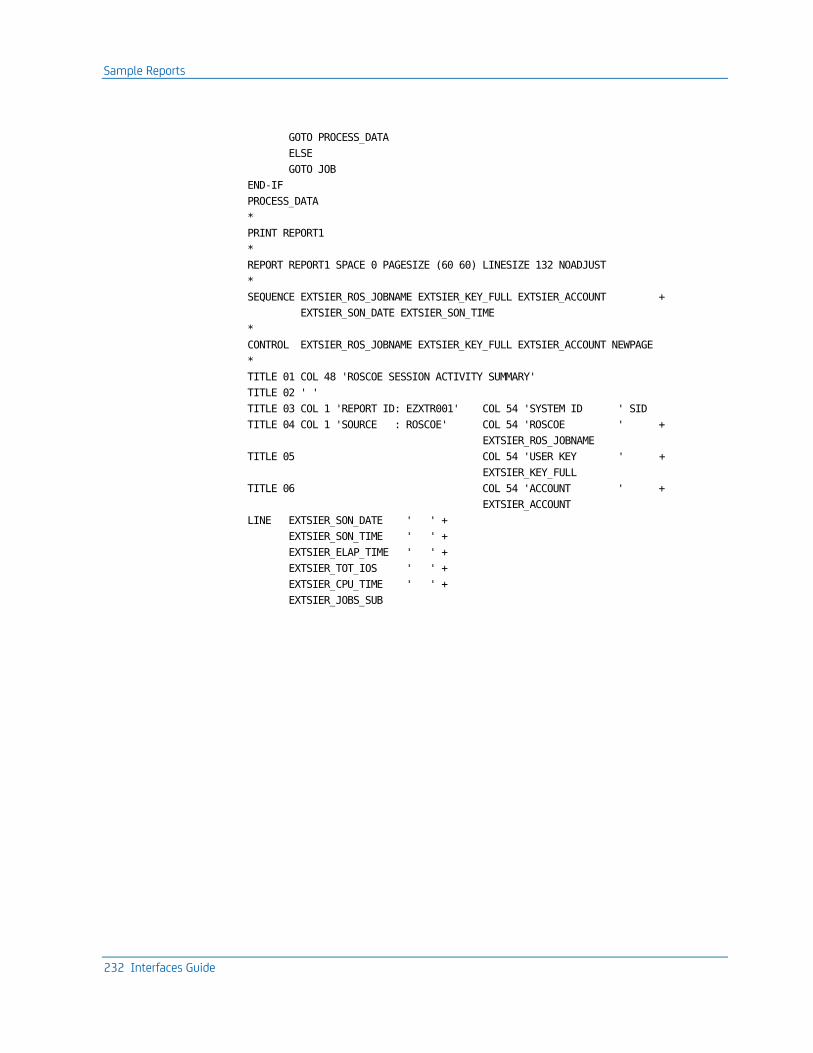
Sample Reports
232 Interfaces Guide
GOTO PROCESS_DATA
ELSE
GOTO JOB
END-IF
PROCESS_DATA
*
PRINT REPORT1
*
REPORT REPORT1 SPACE 0 PAGESIZE (60 60) LINESIZE 132 NOADJUST
*
SEQUENCE EXTSIER_ROS_JOBNAME EXTSIER_KEY_FULL EXTSIER_ACCOUNT +
EXTSIER_SON_DATE EXTSIER_SON_TIME
*
CONTROL EXTSIER_ROS_JOBNAME EXTSIER_KEY_FULL EXTSIER_ACCOUNT NEWPAGE
*
TITLE 01 COL 48 'ROSCOE SESSION ACTIVITY SUMMARY'
TITLE 02 ' '
TITLE 03 COL 1 'REPORT ID: EZXTR001' COL 54 'SYSTEM ID ' SID
TITLE 04 COL 1 'SOURCE : ROSCOE' COL 54 'ROSCOE ' +
EXTSIER_ROS_JOBNAME
TITLE 05 COL 54 'USER KEY ' +
EXTSIER_KEY_FULL
TITLE 06 COL 54 'ACCOUNT ' +
EXTSIER_ACCOUNT
LINE EXTSIER_SON_DATE ' ' +
EXTSIER_SON_TIME ' ' +
EXTSIER_ELAP_TIME ' ' +
EXTSIER_TOT_IOS ' ' +
EXTSIER_CPU_TIME ' ' +
EXTSIER_JOBS_SUB

Reporting Considerations
Chapter 6: The CA Roscoe Interface 233
The sample output will look like this:
121/01/04 ROSCOE SESSION ANALYSIS
REPORT ID: ERXTR001 SYSTEM ID: XAE1
SOURCE : ROSCOE ROSCOE: ROSCOE60
USER KEY: CHIWA01
ACCOUNT: ________________
-------------------------------------------------------------------------------------------------------------------------------
SIGN ON SIGN ON ELAPSED TOTAL CPU TIME JOBS
DATE TIME TIME (HR) IOS (TM UNITS) SUBMITTED
-------------------------------------------------------------------------------------------------------------------------------
02/11/18 12:07:53 2.07662 5768 22 0
02/11/18 15:43:43 4.11261 428 3 1
121/01/04 ROSCOE SESSION ANALYSIS
REPORT ID: ERXTR001 SYSTEM ID: XAE1
SOURCE : ROSCOE ROSCOE: ROSCOE60
USER KEY: COLDE05
ACCOUNT: ________________
-------------------------------------------------------------------------------------------------------------------------------
SIGN ON SIGN ON ELAPSED TOTAL CPU TIME JOBS
DATE TIME TIME (HR) IOS (TM UNITS) SUBMITTED
-------------------------------------------------------------------------------------------------------------------------------
02/11/18 13:30:33 0.02614 309 4 7
02/11/18 13:32:11 3.53465 2938 250 5
Reporting Considerations
This section identifies those areas of the Report Writer operation that are affected by the introduction of Roscoe data. Specifically, the Basic Accounting Table, the Output Data Elements Table, and the TSORATE statement are replaced when producing reports with the CA JARS Interface to Roscoe data.
Roscoe Basic Accounting Table
The following table replaces the batch Basic Accounting Table for designing Roscoe reports:
Interface to Roscoe Basic Accounting Table:
Field Name Field Position Field Length FMT Notes DE ID
CPU Identification 1 1 a 57
Reserved 2-3 2 -
Signon Date 4-9 6 a YYMMDD 60
Signon Time 10-15 6 a HHMMSS 61
Job Name 16-23 8 a user sign-on key (1-8) 04

Reporting Considerations
234 Interfaces Guide
Field Name Field Position Field Length FMT Notes DE ID
Reserved 24-27 4 -
Processing ID 23 1 a "t" 03
Record ID 29-36 8 a "*Roscoe*" 10
Start Time 37-42 6 a HHMMSS Sign-on Time or SMF Roscoe Start Time
12
Run Date 43-48 6 a YYMMDD Sign-on Date or SMF Roscoe Start Date
06
Job Class 49-50 2 a "v " 07
Signoff Time 51-56 6 a HHMMSS 13
User Signon Key 57-76 20 a User Sign-on Key 58
Reserved 77-98 22 -
Terminal VTAM ID 99-106 8 a VTAM Terminal Name 11
Roscoe Job Name 107-114 8 a Smf Roscoe job name 05
Reserved 115-125 10 -
User Session ID 126-130 5 a User session ID 14
Reserved 131-170 40 -
Elapsed Time 171-176 6 p In hours, to 5 decimal places 25, 65, 90
Total CPU Time 177-182 6 p In hours, to 5 decimal places 26, 66, 91
Reserved 183-240 58
Disk Access 241-247 7 p 38
Terminal Access 248-254 7 p 39
Total Accesses 255-261 7 p 40
I/O Index 262-265 4 p 78
Reserved 266-295 30
Group Code #1 Group Code #2 Group Code #3
296
297
298
1
1
1
a
a
a
Blank unless filled by Grouping feature
84
85
86
Reserved 299-300 2

Reporting Considerations
Chapter 6: The CA Roscoe Interface 235
Field Name Field Position Field Length FMT Notes DE ID
User Terminal ID 300-308 8 A0
Reserved 309-364 56 -
Jobs Submitted 365-368 4 p A5
Reserved 369-372 P
Active Time 373-378 6 p In hours, to 5 decimal places A7, A8, A9
Connect Time 379-384 6 p In hours, to 5 decimal places B0, B1, B2
Reserved 385-390 6 -
Resident Time 391-396 6 p In hours, to 5 decimal places B0, B1, B2
Reserved 397-402 6 -
TCB CPU Time 403-408 6 p In hours, to 5 decimal places. C7, C8, C9
Reserved 409-428 19 -
Terminal UCB Number
429-431 3 a B6
Terminal Type 432-434 3 a B7
Reserved 435-436 2 -
Day of Week Code 437 1 a D5, D6
Group Code #4 Group Code #5 Group Code #6
438
439
440
1
1
1
a a a
Blank unless filled by grouping feature.
D7
D8
D9
Reserved 441-445 5 -
Roscoe Session ID 446-453 8 a E4
Reserved 454-502 81 -
User Account Field 503-518 16 E F3
User Count Field 535-539 5 p F5

Reporting Considerations
236 Interfaces Guide
Field Name Field Position Field Length FMT Notes DE ID
Reserved 540-550 11 -
Processor Time 551-556 6 p 999999V99999C hours 29,69
Processor Charge 557-562 6 p 999999999V99C dollars 44
I/O Time 563-568 6 p 999999V99999C hours 30,70
I/O Charge 569-574 6 p 999999999V99C dollars 45
Reserved 575-584 10 -
Total Charge 585-590 6 p 999999999V99C dollars 46
Reserved 591-597 7 -
Connect Charge 598-602 5 p 9999999V99C dollars B3
Reserved 603-608 6 -
Format Indicator: a=alphameric; p=packed decimal.
Chapter 7: The Tape Volume Accounting Interface 237
Chapter 7: The Tape Volume Accounting Interface
The Tape Volume Accounting Interface (TVA) is distributed as part of the CA JARS family of products. It provides a mechanism for users of CA tape management software packages (CA 1 and CA DYNAM/TLMS) to:
■ Account for tape volume usage
■ Add charges for tape volume usage to your CA JARS reports
This section contains the following topics:
Functional Description (see page 237) 21st Century Support (see page 238) Operating Instructions (see page 238) Sample Reports (see page 242) TVA Data Elements (see page 257)
Functional Description
The TVA Interface extracts information from the tape management system master file and creates billing records. The input to the interface is either the TMC (for CA 1) or VMF (for CA DYNAM/TLMS) master file, or both. A control statement is read by the interface to determine the billing period and type of master file(s) being input. The output is a billing file for subsequent processing by CA JARS Wizard.
The TVA Interface executes on the assumption that your tape management system master file contains an account number. For CA 1, the account number is taken from the TMC TMUSER field. For CA DYNAM/TLMS, the account number is taken from the VMF BAJOBACC field.
Note: It is your responsibility to ensure that a valid account number is contained in the appropriate field for your tape management system.
The TVA job streams test for blank account numbers. If found, the account MISC.ACCOUNT is utilized. This account can be changed to meet your requirements by modification of the CA JARS Wizard COMPUTE statement. Refer to the JR70TVA1 and JR70TVA2 CA JARS Wizard control statements in CAJROPTN for details.
This interface can also be used to generate EXTDATA records. EXTDATA records can be used for reporting with CA EARL and CA Easytrieve. The layout and format of the EXTDATA records are described in the chapter "EXTDATA Reporting" in the User Guide.

21st Century Support
238 Interfaces Guide
In addition, the EXTDATA records can be used in conjunction with CA PMA Chargeback to create billing and chargeback systems for tape resource utilization.
21st Century Support
Due to architectural limitations, the date normalization routines will not process dates beyond 2027 properly. Therefore, dates may only be between January 1, 1960 and December 31, 2027 for normalization logic. Tape catalog dates beyond 2027 are treated as the last day of 2027 for purposes of determining slot times.
CA DYNAM/TLMS does not keep the actual EXPDT values in its catalog, depending on the TLMS options in effect. However, TLMS always maintains the scratched date. If this date is zero, then the tape is active, otherwise, by definition, the field contains the date the tape was scratched. In order to calculate the slot time, CA use these field contents as follows:
■ If it is non-zero, CA uses its contents directly.
■ If it is zero, CA uses the value from the end date (control card).
Control card date format is MM/DD/YY. Anytime 'YY' is less than 60, it will be treated as if it were 20YY. For example, in the 21st century.
Operating Instructions
The TVA Interface should be run as the last step of the CA 1 TMSCLEAN, or CA DYNAM/TLMS Tape Retention System execution. The region size suggested to execute the interface is approximately 150K. The TVA Interface reads a required input control statement to determine the billing period and the type of input. The control statement is read through CAIJFIN in the following format.
TVA Control Statement Layout
Position Field Length Fmt Field Name Notes
1-8 8 a Start Date Start date of billing period (see note below)
9 1 Reserved
10-17 8 a End Date End date of billing period (see note below)
18 1 Reserved
19-22 4 a Tape System Flag 1
CA 1: CA 1 TMC input TLMS: CA DYNAM/TLMS VMF input Default is CA 1

Operating Instructions
Chapter 7: The Tape Volume Accounting Interface 239
Position Field Length Fmt Field Name Notes
23 1 Reserved
24-27 4 a Tape System Flag 2
CA 1: CA 1 TMC input TLMS: CA DYNAM/TLMS VMF input Default is CA 1
Note: The Start Date and End Date field names are used to filter data from the input for a user defined billing period. If left blank the field name defaults to the current system date.
TVA File Names
The interface requires several files to execute. The following table provides a list of these files, their data set names, and a description of each.
DDName Description
STEPLIB This statement describes the load library loaded from the distribution tape.
CAIJFPR This statement describes the SYSOUT data set for generated display messages and reports.
CAIJFSN This statement describes the SYSOUT data set for generated SNAP dumps.
CAIJFIN This statement describes the data set that contains the TVA control statement.
CAIJSACT This optional DD statement indicates to the interfact that EXTDATA records are to be written as well. This file must have these attributes:
RECFM=VB LRECL=8188 BLKSIZE=8192 or more
CAIVMFI This optional statement describes the input file (CA DYNAM/TLMS VMF) to be processed. It is required if TLMS is specified in the TVA control statement.
CAITMCI This optional statement describes the input file (CA 1 TMC) to be processed. It is required if CA 1 or the default is specified in the TVA control statement.

Operating Instructions
240 Interfaces Guide
DDName Description
CAITVAS6 This statement describes the output file written by TVA. This is the file that is processed later by CA JARS Wizard to create debit statements and reports. Since TVA is run as the last step in your daily tape system clean job, it is suggested that this file be defined as a GDG.
This file must have the following attributes:
RECFM=FB
LRECL=270
BLKSIZE=6750

Operating Instructions
Chapter 7: The Tape Volume Accounting Interface 241
TVA Sample JCL
The following is a sample run deck for executing the TVA Interface.
//TVARUN JOB ,'RUN TVA INTERFACE',CLASS=A,MSGCLASS=M
//*
//* DOC: THIS JOB EXECUTES THE CA JARS/TVA INTERFACE PROGRAM
//* THIS JCL REFERS TO DATA SET NAME CAI.CAJRLOAD ON THE
//* STEPLIB DD. THIS NAME MUST MATCH THE ONE WITH WHICH
//* YOU LOADED THE LOAD LIBRARY FROM THE DISTRIBUTION TAPE.
//*
//* CAIJFPR DD TVA MESSAGE AND REPORT OUTPUT
//* CAIJFSN DD SNAP DUMP
//* CAIJRIN DD CONTROL CARD INPUT (INPUT CONTROL CARD REQUIRED
//* CAIVMFI DD CA DYNAM/TLMS INPUT MASTER FILE
//* (OPTIONAL DEPENDING ON CONTROL CARD)
//* CAITMCI DD CA 1 INPUT MASTER FILE
//* (OPTIONAL DEPENDING ON CONTROL CARD)
//* CAITVAS6 DD TVA OUTPUT BILLING FILE
//*
//TVA01 EXEC PGM=JSTA0020,REGION=150K
//*
//STEPLIB DD DSN=CAI.CAJRLOAD,DISP=SHR
//*
//CAIJFPR DD SYSOUT=*
//CAIJFSN DD SYSOUT=*
//SYSPRINT DD SYSOUT=*
//CAIJFIN DD *
MM/DD/YY MM/DD/YY CA 1 (ONLY CA 1 MASTER FILE IS PROCESSED)
OR
MM/DD/YY MM/DD/YY CA 1 CA 1 (ONLY CA 1 MASTER FILE IS PROCESSED)
OR
MM/DD/YY MM/DD/YY TLMS (ONLY TLMS MASTER FILE IS PROCESSED)
OR
MM/DD/YY MM/DD/YY TLMS TLMS (ONLY TLMS MASTER FILE IS PROCESSED)
OR
MM/DD/YY MM/DD/YY CA 1 TLMS (BOTH MASTER FILES ARE PROCESSED)
OR
MM/DD/YY MM/DD/YY TLMS CA 1 (BOTH MASTER FILES ARE PROCESSED)
OR
MM/DD/YY MM/DD/YY TLMS (BOTH MASTER FILES ARE PROCESSED)
OR
MM/DD/YY MM/DD/YY CA 1 (ONLY CA 1 MASTER FILE IS PROCESSED)
OR
MM/DD/YY MM/DD/YY (ONLY CA 1 MASTER FILE IS PROCESSED)
/*
//CAIVMFI DD DSN=TLMS.VMF.MASTER.FILE,DISP=SHR
//CAITMCI DD DSN=CA 1.TMC.MASTER.FILE,DISP=SHR
//CAITVAS6 DD DSN=TVA.BILLING.FILE,DISP=(,CATLG,DELETE),

Sample Reports
242 Interfaces Guide
// DCB=(RECFM=FB,LRECL=270,BLKSIZE=6750),
// SPACE=(CYL(5,5)),
// UNIT=SYSDA,VOL=SER=WORK01
//CAIJSACT DD DSN=CAI.TVA.EXTDATA,
// DISP=(NEW,CATLG,DELETE),
// UNIT=uuuu,
// SPACE=(CYL,(pp,ss),RLSE),
// DCB=(RECFM=VB,LRECL=8188,BLKSIZE=bbbb),
// VOL=SER=vvvvvv
/*
//
Sample Reports
The interface uses the CA JARS Wizard Report Writer to read the TVA billing file. A record description for the TVA billing file is provided in the CA JARS Wizard combined billing glossary, JR70CBF. Two sample reports, created using CA JARS Wizard, are also provided with the interface. The report samples shown in this chapter are intended to illustrate the use of CA JARS Wizard not how to charge for tape volume usage.
Sample reports are also provided for EXTDATA using CA EARL and CA Easytrieve. Again these sample are provided to illustrate the use of EXTDATA in reporting, and not to illustrate the use of the generated EXTDATA for chargeback.
Distributed Sample Source Code
The first report, JR70TVA1, shows how CA JARS debit records can be created. The debit records are read in a product run that reports on charges by account. Tape volume usage charges are added to the other charges that are calculated on an account basis.
The second report, JR70TVA2, is a sample report showing tape volume usage by account number. Each report is described on the following pages. A description of the JR70CBF glossary is contained in the CA JARS Wizard Reference Guide. A complete description of the function of the JR70CBF glossary is provided in "Appendix B" of the Systems Programmer Guide. A description of the CA JARS Wizard data element names to use in CA JARS Wizard programs to process the TVA billing records is contained later in this chapter. TVA Data Elements (see page 257)
The source code for both of these CA JARS Wizard programs is distributed in the AAJ1OPTN distribution library and is copied to CAJROPTN at APPLY time by SMP. You are encouraged to use these programs as samples to help you develop your own CA JARS Wizard programs to process the TVA billing data.

Sample Reports
Chapter 7: The Tape Volume Accounting Interface 243
JR70TVA1: Debit Record Creation
In JR70TVA1, CA JARS Wizard is used to:
■ Calculate the charge for the user. In this sample the charge is based on the elapsed time of use of a tape volume. Because CA JARS Wizard has a flexible language for computing new fields, and since information about the tape volume is carried in the TVA billing record, the charge can be based on anything in the record. For example, a surcharge could be charged for 1600 BPI density tape volumes.
■ Sum the charges for the account and print a report showing the charge by account.
■ Write a debit record for each account. The debit record contains the account information and the charge that was calculated. All debit records are in a CA JARS run that reports on charges by account. The charge for tape volume usage is added to the other charges that are calculated on an account basis.
JR70TVA1 executes on the assumption that your tape management system master file contains an account number. For CA 1, the account number is taken from the TMC TMUSER field. For CA DYNAM/TLMS, the account number is taken from the VMF BAJOBACC field.
Note: It is your responsibility to ensure that a valid account number is contained in the appropriate field for your tape management system.
JR70TVA1 does test for a blank account number. If found, JR70TVA1 uses the account MISC.ACCOUNT for the account number. You can alter this accordingly.
Be sure to include DD statements for the following ddnames:
■ CAIJWI (your TVA billing file)
■ CAIJOP (the report file for the debit record)

Sample Reports
244 Interfaces Guide
The sample report produced with the debit record output file with JR70TVA1 is shown next.
TOTAL TAPE SYSTEM CHARGES BY ACCOUNT 18 OCT 1998 PAGE 1
TVA BILLING
ACCOUNT NUMBER TOTAL CHARGE RECORDS DAYS OF USAGE
---------------- -------------- ----------- -------------
AMOCO $145.00 1 29
CAP1.FIMS.FEDX $145.00 1 29
TERRY DENNIS $145.00 1 29
BETTYE SPARKS $435.00 3 87
BEV HALWA $145.00 1 29
BF-MEMBERS 6/79 $145.00 1 29
BILL VALLIERE $1,015.00 7 203
BKUP DS 080679 $580.00 4 116
BKUP HAW MOVE $145.00 1 29
BKUP MIMS 1.3 $145.00 1 29
BKUP OF OPT.REL $145.00 1 29
BKUP OF TLMSII $145.00 1 29
BKUP REL-1.2 $145.00 1 29
BKUP SL,RL,CL,R $145.00 1 29
BKUP 79-REL 2.0 $145.00 1 29
BKUP-071578-1.0 $145.00 1 29
.
.
.
TVA BILLING
ACCOUNT NUMBER TOTAL CHARGE RECORDS DAYS OF USAGE
---------------- -------------- ----------- -------------
GRAND TOTAL $1,581,175.00 11,977 316,235

Sample Reports
Chapter 7: The Tape Volume Accounting Interface 245
JR70TVA1 Control Statements
PARAMETER XREF
CALL WIZSETT
INPUT JR70CBF
DEFINE OFILL1(1)(C) = ' '
DEFINE ODEBIT(8)(C) = 'DEBIT '
DEFINE OCPUID(1)(C) = ' '
DEFINE OUSERID(8)(C) = ' '
DEFINE ODATE(6)(C) = 'yymmdd'
DEFINE OJOB(8)(C) = 'TVA-PROC'
DEFINE OTIME(6)(C) = 'hhmmss'
DEFINE OPROGRAMMER(20)(C) = ' '
DEFINE ODEBITAMT(6)(P)(.2) = 0
DEFINE ORENTDAYS(6)(P) = 0
DEFINE USEDAYS(6)(P) = 0
COMPUTE MOVE TODAY TO ODATE(6)(YYMMDD)
COMPUTE WKTIM(6)(P) = TOD
COMPUTE WKHRS(6)(N)(.4) = WKTIM / 3600
COMPUTE WKHR2(2)(C) = WKHRS
COMPUTE WKMIN(6)(N)(.4) = (WKTIM / 60) - (WKHR2 * 60)
COMPUTE WKMI2(2)(C) = WKMIN
COMPUTE WKSEC(2)(N) = WKTIM - ((WKHR2 * 3600) + (WKMI2 * 60))
COMPUTE OTIME(1,2) = WKHRS
COMPUTE OTIME(3,2) = WKMIN
COMPUTE OTIME(5,2) = WKSEC
SELECT REC/TYPE EQ 'T' AND SUB/REC/TYPE EQ 'M'
COMPUTE(P) IF T.ACCOUNT/NUMBER EQ BLANK THEN
OACCT(C)(16) EQ 'MISC. ACCOUNT ' ELSE
OACCT EQ T.ACCOUNT/NUMBER
COMPUTE RENTDAYS = (RENTDAYS + VOL/RENT/TIME)
COMPUTE USEDAYS = (RENTDAYS / 86400)
COMPUTE ODEBITAMT = (USEDAYS * 0.1250)
SORT OACCT, T.VOLUME/SERIAL
BREAK OACCT
HEADING1C TOTAL TAPE SYSTEM CHARGES BY ACCOUNT
LIST (SUM) OACCT 'ACCOUNT NUMBER', ODEBITAMT($) 'TOTAL CHARGE',
COUNT 'TVA BILLING/RECORDS', USEDAYS 'DAYS OF USAGE'
OUTPUT (SUM) FILE,RECFM=FB,R=80,B=800,
ITEM = OFILL1,ODEBIT,OCPUID,OUSERID,OACCT,ODATE,OJOB,OTIME,
OPROGRAMMER,ODEBITAMT
Sample Reports
246 Interfaces Guide
JR70TVA1 Execution Description
The control statements used in JR70TVA1 are described below. Complete descriptions of all CA JARS Wizard control statements can be found in the CA JARS Wizard Reference Guide.
PARAMETER
This control statement specifies options for a CA JARS Wizard run. XREF creates a cross reference of the data fields used in the run and the statements they are found in. This cross reference listing is printed in addition to the control statements and the report for the run.
INPUT
The INPUT statement identifies the CA JARS Wizard glossary or the input files for the run. In JR70TVA1, the INPUT statement lists the JR70CBF glossary as the glossary for the primary input file for the run.
DEFINE
11 DEFINE statements are given in JR70TVA1. Each define a field for the run.
The first nine DEFINE statements define fields for the debit record:
1. OFILL1:
One byte field. Initialized as a blank.
2. ODEBIT:
Eight byte field. Initialized as DEBIT. This field identifies the statement as a DEBIT statement.
3. OCPUID:
One byte field. Initialized as a blank: used to identify the CPU.
4. OUSERID:
Eight byte field. Initialized as blanks: used for user identification.
5. ODATE:
Six byte field. Initialized as blanks: used for the date (YYMMDD).
6. OJOB:
Eight byte field. Initialized as blanks: used for the job name.
7. OTIME:
Six byte field. Initialized as blanks: used for the time (HHMMSS).
8. PROGRAMMER:
Twenty byte field. Initialized as blanks: used to identify the programmer.

Sample Reports
Chapter 7: The Tape Volume Accounting Interface 247
9. ODEBITAMT:
Six byte field. Initialized as zero: used for the debit amount.
The remaining DEFINE statements are
10. RENTDAYS:
Six byte field. Used to hold the number of seconds of tape volume usage.
11. USEDAY:
Six byte field. Used to hold the number of days of tape volume usage.
SELECT
SELECT statements indicate which records in the primary input file are to be processed. JR70TVA1 uses the JR70CBF glossary for combined billing. In JR70TVA1, the SELECT statement identifies the record type to be processed (T) and the subrecord type to be processed (M). This identifies the JR70CBF record type and subrecord type for the TVA billing records.
COMPUTE
Four COMPUTE statements are executed in JR70TVA1:
The first COMPUTE statement evaluates the value of the account number contained in the billing record. It also defines a new field, OACCT (16 bytes), and assigns a value to it based on the results of the evaluation. If the account number is blank, OACCT is assigned the value of MISC.ACCOUNT. Otherwise, OACCT is assigned the value of the account number.
Notice the (P) suffix code appended to the first compute statement. This suffix indicates that the COMPUTE should take place before the primary input file is sorted. This is needed since the SORT occurs on OACCT field.
The remaining three COMPUTE statements assign values to the fields: RENTDAYS, USEDAYS, and ODEBITAMT. RENTDAYS is assigned the value of the total number of seconds of tape volume usage for an account. USEDAYS is assigned the value of the total number of days of tape volume usage for an account; it is computed using RENTDAYS divided by the number of seconds in a day (86400). ODEBITAMT is assigned the charge for tape volume usage.
SORT
This statement identifies the sequence in which the input records should be sorted prior to processing. Here the sort is performed on OACCT (the account number) and T.VOLUME/SERIAL (the tape's volume serial number).
BREAK
This statement is used to define logical group of records. Here data is split into groups by OACCT. Records with the same account number is grouped together.

Sample Reports
248 Interfaces Guide
HEADING
HEADING specifies a title for the report. The title for this report is TOTAL TAPE SYSTEM CHARGES BY ACCOUNT.
LIST(SUM)
A summary listing is requested with the output file. Each line of the summary listing lists the debit information for a different account. The LIST(SUM) statement identifies the date fields to be summarized and printed. This data includes the:
■ Account number
■ Calculated total charge for the account
■ Number of TVA billing records for the account
■ Number of days of tape volume usage for the account
OUTPUT
One debit record is produced for each unique account. All records are written to the file identified by ddname CAIJWOP. The OUTPUT statement lists the fields to be included in each debit record.

Sample Reports
Chapter 7: The Tape Volume Accounting Interface 249
JR70TVA2 Report Sample
The following report shows tape volume usage by account number.
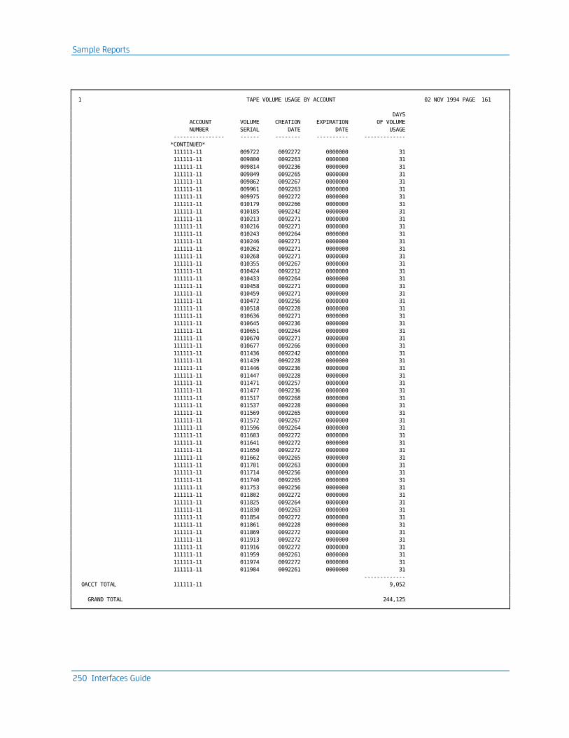
Sample Reports
250 Interfaces Guide
1 TAPE VOLUME USAGE BY ACCOUNT 02 NOV 1994 PAGE 161
DAYS
ACCOUNT VOLUME CREATION EXPIRATION OF VOLUME
NUMBER SERIAL DATE DATE USAGE
---------------- ------ -------- ---------- -------------
*CONTINUED*
111111-11 009722 0092272 0000000 31
111111-11 009800 0092263 0000000 31
111111-11 009814 0092236 0000000 31
111111-11 009849 0092265 0000000 31
111111-11 009862 0092267 0000000 31
111111-11 009961 0092263 0000000 31
111111-11 009975 0092272 0000000 31
111111-11 010179 0092266 0000000 31
111111-11 010185 0092242 0000000 31
111111-11 010213 0092271 0000000 31
111111-11 010216 0092271 0000000 31
111111-11 010243 0092264 0000000 31
111111-11 010246 0092271 0000000 31
111111-11 010262 0092271 0000000 31
111111-11 010268 0092271 0000000 31
111111-11 010355 0092267 0000000 31
111111-11 010424 0092212 0000000 31
111111-11 010433 0092264 0000000 31
111111-11 010458 0092271 0000000 31
111111-11 010459 0092271 0000000 31
111111-11 010472 0092256 0000000 31
111111-11 010518 0092228 0000000 31
111111-11 010636 0092271 0000000 31
111111-11 010645 0092236 0000000 31
111111-11 010651 0092264 0000000 31
111111-11 010670 0092271 0000000 31
111111-11 010677 0092266 0000000 31
111111-11 011436 0092242 0000000 31
111111-11 011439 0092228 0000000 31
111111-11 011446 0092236 0000000 31
111111-11 011447 0092228 0000000 31
111111-11 011471 0092257 0000000 31
111111-11 011477 0092236 0000000 31
111111-11 011517 0092268 0000000 31
111111-11 011537 0092228 0000000 31
111111-11 011569 0092265 0000000 31
111111-11 011572 0092267 0000000 31
111111-11 011596 0092264 0000000 31
111111-11 011603 0092272 0000000 31
111111-11 011641 0092272 0000000 31
111111-11 011650 0092272 0000000 31
111111-11 011662 0092265 0000000 31
111111-11 011701 0092263 0000000 31
111111-11 011714 0092256 0000000 31
111111-11 011740 0092265 0000000 31
111111-11 011753 0092256 0000000 31
111111-11 011802 0092272 0000000 31
111111-11 011825 0092264 0000000 31
111111-11 011830 0092263 0000000 31
111111-11 011854 0092272 0000000 31
111111-11 011861 0092228 0000000 31
111111-11 011869 0092272 0000000 31
111111-11 011913 0092272 0000000 31
111111-11 011916 0092272 0000000 31
111111-11 011959 0092261 0000000 31
111111-11 011974 0092272 0000000 31
111111-11 011984 0092261 0000000 31
-------------
OACCT TOTAL 111111-11 9,052
GRAND TOTAL 244,125

Sample Reports
Chapter 7: The Tape Volume Accounting Interface 251
JR70TVA2 Control Statements
PARAMETER XREF
INPUT JR70CBF
DEFINE RENTDAYS(6)(P) = 0
DEFINE CRTDT(4)(P) = 0
DEFINE SCRTDT(4)(P) = 0
SELECT REC/TYPE EQ 'T' AND SUB/REC/TYPE EQ 'M'
COMPUTE(P) IF T.ACCOUNT/NUMBER EQ BLANK THEN
OACCT(C)(16) EQ 'MISC. ACCOUNT ' ELSE
OACCT EQ T.ACCOUNT/NUMBER
COMPUTE CRTDT EQ T.CREATE/DATE
COMPUTE SCRTDT EQ T.SCRATCH/DATE
COMPUTE RENTDAYS = (VOL/RENT/TIME / 86400)
SORT OACCT, T.VOLUME/SERIAL
BREAK OACCT
HEADING1C TAPE VOLUME USAGE BY ACCOUNT
LIST OACCT 'ACCOUNT/NUMBER',
T.VOLUME/SERIAL,
CRTDT(NV) 'CREATION/DATE',
SCRTDT(NV) 'EXPIRATION/DATE',
RENTDAYS 'DAYS/OF VOLUME/USAGE'
JR70TVA2 Execution Description
The control statements used in JR70TVA2 are described below. Complete descriptions of all CA JARS Wizard control statements can be found in the CA JARS Wizard Reference Guide.
PARAMETER
This control statement specifies options for a CA JARS Wizard run. XREF creates a cross reference of the data fields used in the run and the statements they are found in. This cross reference listing is printed in addition to the control statements and the report for the run.
INPUT
The INPUT statement lists the JR70CBF glossary as as the glossary for the primary input file for the run.
DEFINE
The three DEFINE statements define the following fields:
RENTDAYS:
Six byte field. Used to hold the number of days of tape volume usage.
CRTDT:
Three byte field. Used to hold the creation date (YYDDD) of the tape volume.
Sample Reports
252 Interfaces Guide
SCRDT:
Three byte field. Used to hold the expiration date (YYDDD) for the tape volume.
SELECT
The SELECT statement identifies the record type and subrecord type for the TVA billing record.
COMPUTE
The first COMPUTE statement evaluates the value of the account number contained in the billing record. It also defines a new field, OACCT (16 bytes), and assigns a value to it based on the results of the evaluation. If the account number is blank, OACCT is assigned the value of MISC.ACCOUNT. Otherwise, OACCT is assigned the value of the account number.
Notice the (P) suffix code appended to the first compute statement. This suffix indicates that the COMPUTE should take place before the primary input file is sorted. This is needed since the SORT occurs on OACCT field.
The remaining COMPUTE statements assign values to the fields: CRTDT, SCRTDT, and RENTDAYS.
SORT
This statement identifies the sequence in which the input records should be sorted prior to processing. Here the sort is performed on OACCT (the account number) and T.VOLUME/SERIAL (the tape's volume serial number).
BREAK
BREAK statements define logical groups of records. Here data is split into groups by account number. Records with the same account number is grouped together.
HEADING
HEADING specifies a title for the report. Here the title for the report is TAPE VOLUME USAGE BY ACCOUNT.
LIST
The LIST statement identifies the data elements to be printed. This includes:
■ Account number
■ Creation date (YYDDD)
■ Expiration date (YYDDD)
■ Days of volume usage

Sample Reports
Chapter 7: The Tape Volume Accounting Interface 253
EXTDATA Reports
There are sample CA Earl and CA Easytrieve reports that will process the ADABAS Interface EXTDATA records.
Note: The EXTDATA record layout is described in the chapter "EXTDATA Reporting" in the User Guide.
OPTION LIST OFF
NOTE ******************************************************************
NOTE * REPORT ID: ERXTT001 *
NOTE * REPORT NAME: TAPE VOLUME ACCOUNTING INTERVAL REPORT *
NOTE * *
NOTE * DESCRIPTION: THIS REPORT WILL LIST ALL OF THE TAPES *
NOTE * IN A TAPE LIBRARY BASED UPON THE ACCOUNTING *
NOTE * INFORMATION. INFORMATION REPORTED: THE FIRST *
NOTE * DATASET NAME ON THE TAPE, THE CREATION DATE *
NOTE * AND TIME, THE SCRATCH DATE, AND THE LOCATION. *
NOTE * *
NOTE * RECORD TYPES: MRXTHDR, *
NOTE * MRXTSIET *
NOTE * *
NOTE * EXTDATA RECORD: SIET *
NOTE * *
NOTE * MACROS: *
NOTE ******************************************************************
OPTION PRINTER = 132
OPTION PAGE = 60
OPTION PRECISION = ALL
OPTION CPAGE = 60
HISTIN: FILE JARS RECORD=3697
DEF INAREA 1-3697 X
COPY MRXTHDR
COPY MRXTSIET
NOTE ******************************************************************
NOTE * SELECTING FROM HISTORY FILE EXTDATA, SPECIFICALLY SIET *
NOTE ******************************************************************
!
IF PROCID NOT = ':' OR
EXTTYPE NOT = 'SIET'
THEN GOTO START
ENDIF
!
NOTE ******************************************************************
NOTE * REPORT PROCESSING SECTION *
NOTE ******************************************************************
!
REPORT 'TAPE INVENTORY SNAPSHOT'
TITLE ' '
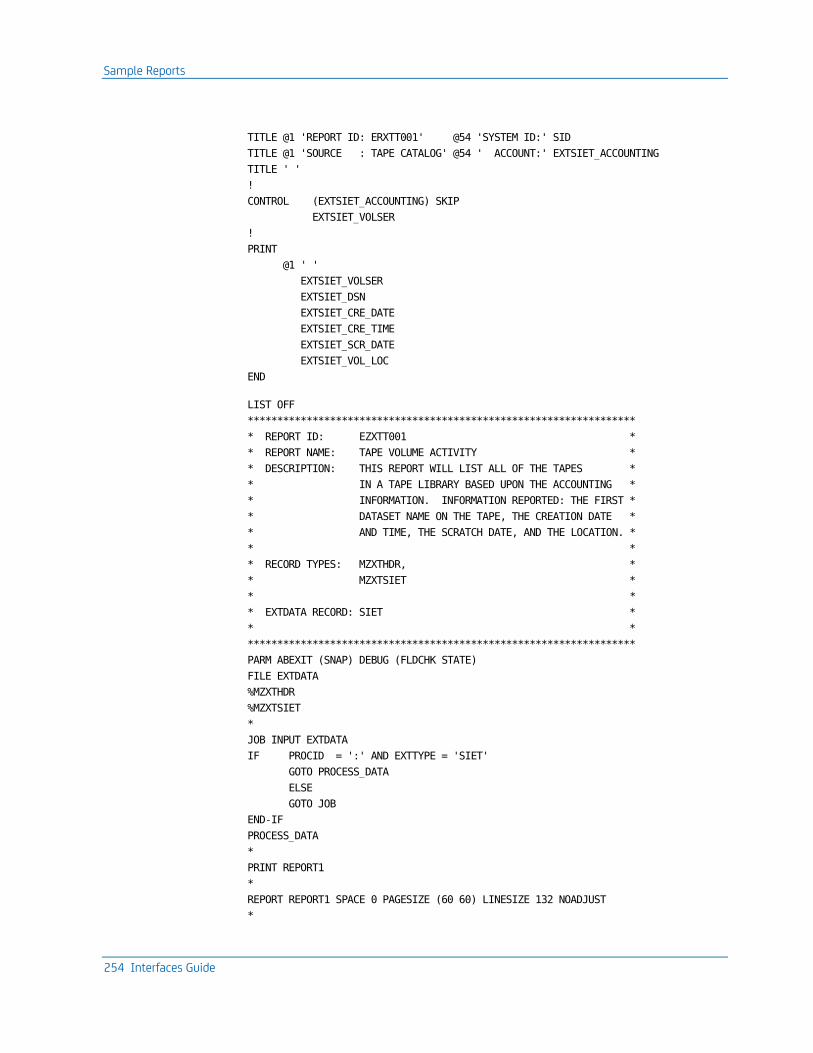
Sample Reports
254 Interfaces Guide
TITLE @1 'REPORT ID: ERXTT001' @54 'SYSTEM ID:' SID
TITLE @1 'SOURCE : TAPE CATALOG' @54 ' ACCOUNT:' EXTSIET_ACCOUNTING
TITLE ' '
!
CONTROL (EXTSIET_ACCOUNTING) SKIP
EXTSIET_VOLSER
!
@1 ' '
EXTSIET_VOLSER
EXTSIET_DSN
EXTSIET_CRE_DATE
EXTSIET_CRE_TIME
EXTSIET_SCR_DATE
EXTSIET_VOL_LOC
END
LIST OFF
******************************************************************
* REPORT ID: EZXTT001 *
* REPORT NAME: TAPE VOLUME ACTIVITY *
* DESCRIPTION: THIS REPORT WILL LIST ALL OF THE TAPES *
* IN A TAPE LIBRARY BASED UPON THE ACCOUNTING *
* INFORMATION. INFORMATION REPORTED: THE FIRST *
* DATASET NAME ON THE TAPE, THE CREATION DATE *
* AND TIME, THE SCRATCH DATE, AND THE LOCATION. *
* *
* RECORD TYPES: MZXTHDR, *
* MZXTSIET *
* *
* EXTDATA RECORD: SIET *
* *
******************************************************************
PARM ABEXIT (SNAP) DEBUG (FLDCHK STATE)
FILE EXTDATA
%MZXTHDR
%MZXTSIET
*
JOB INPUT EXTDATA
IF PROCID = ':' AND EXTTYPE = 'SIET'
GOTO PROCESS_DATA
ELSE
GOTO JOB
END-IF
PROCESS_DATA
*
PRINT REPORT1
*
REPORT REPORT1 SPACE 0 PAGESIZE (60 60) LINESIZE 132 NOADJUST
*

Sample Reports
Chapter 7: The Tape Volume Accounting Interface 255
SEQUENCE EXTSIET_ACCOUNTING EXTSIET_VOLSER
*
CONTROL EXTSIET_ACCOUNTING NEWPAGE EXTSIET_VOLSER NOPRINT
*
TITLE 01 COL 52 'TAPE INVENTORY LISTING'
TITLE 02 ' '
TITLE 03 COL 1 'REPORT ID: EZXTT001' COL 54 'SYSTEM ID ' SID
TITLE 04 COL 1 'SOURCE : TAPE CATALOG' COL 54 'ACCOUNT ' +
EXTSIET_ACCOUNTING
LINE EXTSIET_VOLSER ' ' +
EXTSIET_DSN ' ' +
EXTSIET_CRE_DATE ' ' +
EXTSIET_CRE_TIME ' ' +
EXTSIET_SCR_DATE ' ' +
EXTSIET_VOL_LOC

Sample Reports
256 Interfaces Guide
The sample output will look like this:
108/01/04 TAPE INVENTORY SNAPSHOT
REPORT ID: ERXTT001 SYSTEM ID: XE44
SOURCE : TAPE CATALOG ACCOUNT:
-------------------------------------------------------------------------------------------------------------------------------
VOLUME FIRST DSN CREATION CREATION SCRATCH VOLUME
SERIAL ON VOLUME DATE TIME DATE LOCATION
-------------------------------------------------------------------------------------------------------------------------------
100572 CAI.DASD.DNGAL.TESTTAPE.D042187 87.111 13:24:34 00.000 DC
100674 CAI.DASD.DNSAW.ARC.A120986 86.343 13:01:54 00.000 DC
100689 BFCS.EPNE433.FILE1 89.104 12:01:51 00.000 DC
100721 CAI.DASD.BACKUP.D091786 86.260 11:56:15 00.000 DC
100726 CAI.DASD.DNSAW.ARC.A120986 86.343 13:34:02 00.000 DC
100743 BFCS.EPNE433.FILE1 89.104 12:05:04 00.000 DC
100756 CAI.DASD.DNSAW.ARC.A120986 86.343 13:16:44 00.000 DC
100792 MIKES.MNT8702.CICSV170.BACKUP 87.329 17:26:55 00.000 DC
100795 CAI.INSTALL 88.301 11:54:00 00.000 DC
100798 MIKES.MNT8702.CICSV370.BACKUP 87.329 17:17:06 00.000 DC
100800 MIKES.MNT8702.CICSV161.BACKUP 87.329 17:18:00 00.000 DC
100812 MIKES.MNT8702.CICSV 87.329 16:45:55 00.000 DC
100814 MIKES.MNT8702.CICSV 87.329 16:41:37 00.000 DC
100815 DAWYA01.TEST 87.302 14:29:45 00.000 DC
100819 MIKES.MNT8702.CICSV 87.329 16:35:01 00.000 DC
100822 SHACH02.BK72.SOURCE 87.329 16:20:37 00.000 DC
100830 CAIPRFBU.JARS.V51BETA.PROFILE 88.047 17:49:09 00.000 DC
100836 CAI.SYSQA.QA.DSS.SCHD8811.BACKUP 88.344 16:35:22 00.000 DC
100922 CAI.DASD.DNSAW.ARC.A060587 87.156 18:17:15 00.000 DC
100949 MVSSYS.ARCHLOG1.B0000090 91.046 14:33:36 00.000 DC
100953 CAI.OPERA.SYSPRINT.D051187 87.131 18:47:00 00.000 DC
100978 CAI.TLMS.R53.BKUP.BETA.LISTINGS 87.137 11:38:52 00.000 DC
101016 TRANBACK.TRAN.BASE.CNTLA2I2 88.158 17:32:06 00.000 DC
101034 MVSSYS.ARCHLOG2.B0000334 91.315 13:31:11 00.000 DC
101044 CAI.SYSQA.QA.DSS.SCHD8811.BACKUP 88.344 16:28:48 00.000 DC
101054 CAI.IMP.SYSPRINT.D021178 87.042 14:40:50 00.000 DC
101130 DEMO.CA7.R29.LOGTAPE.G0001V00 89.151 17:01:44 00.000 DC
101133 DEMO.CA7.R29.LOGARCH.G0001V00 89.151 17:03:25 00.000 DC
101164 SYS.SMFDATA.MS031287.T1608P1 87.071 16:11:42 00.000 DC
101187 SYS.SMFDATA.MS031287.T1608A1 87.071 16:11:45 00.000 DC
101195 BLURI01.QAUNI.PROFILE 88.315 15:28:21 00.000 DC
101251 CAI.TLMS.R52.CAIHELP 87.152 19:43:06 00.000 DC
101279 CAI.TLMS.R5310.G8805.LISTINGS 88.162 11:32:16 00.000 DC
101295 CAI.TLMS.R5310.G8805.LISTINGS 88.162 11:28:17 00.000 DC
101396 CAI.TLMS.R5310.G8805.LISTINGS 88.162 11:45:51 00.000 DC
101399 APDAD.MV71.LD 88.363 16:13:08 00.000 DC
101402 CAI.TLMS.R5310.G8805.LISTINGS 88.162 11:54:18 00.000 DC
101411 ASM2.ARCH.MASTER.TAPE 88.211 17:12:46 00.000 DC
101416 CAI.TLMS.R53.BKUP.BETA.LISTINGS 87.137 11:40:08 00.000 DC
101457 CAI.DASD.BACKUP.D122286 86.356 11:41:13 00.000 DC
101520 MVSSYS.ARCHLOG2.B0000169 91.136 23:57:22 00.000 DC
101528 APDAD.DEMOJCL 88.357 10:32:53 00.000 DC
101534 MVSSYS.ARCHLOG1.B0000166 91.136 23:17:14 00.000 DC
101572 MVSSYS.ARCHLOG2.B0000389 91.354 17:23:51 00.000 DC
101587 MARKN.BK300601.V1 87.310 08:28:56 00.000 DC
101595 WILMI01.BACK8701.DISTLOAD 87.070 20:02:19 00.000 DC
101657 CAI.TLMS.R5310.BKUP.BETA.LISTINGS 87.288 20:23:43 00.000 DC
101659 CAI.TLMS.R5310.BKUP.BETA.LISTINGS 87.288 20:26:27 00.000 DC
101719 CAI.TLMS.R53.BKUP.BETA.LISTINGS 87.137 12:01:47 00.000 DC
101722 CAI.DASD.DNGAL.TESTTAPE.D041587 87.105 14:31:20 00.000 DC

TVA Data Elements
Chapter 7: The Tape Volume Accounting Interface 257
TVA Data Elements
Name Pos Len Format Descriptions
RDW 001 004 B Record descriptor word
REC/TYPE 083 001 C Record Type Code, Character 'T'
SUB/REC/TYPE 084 001 C Record Sub-Type Code, Character 'M'
VOL/RENT/TIME 104 004 B Tape volume rental time in seconds
T.SLOT/NUMBER 118 004 C Tape slot/cabinet number
T.CREATE/TIME 122 004 P Tape creation time
T.CREATE/DATE 126 004 P Tape creation date
T.SCRATCH/DATE 130 004 P Volume scratch date
T.VOLUME/SERIAL 134 006 C Volume serial number of tape
T.TECH/CODE 140 001 H Recording technique code
T.RECORDING/TECH 141 025 C Recording technique
T.DENSITY/CODE 166 001 H Tape density code
T.DENSITY 167 004 C Tape density
T.LABEL/CODE 171 001 H Tape label type code
T.LABEL/TYPE 172 004 C Tape label type
T.VOL/LOCATION 176 004 C Tape volume location
T.VOL/MOVE/DATE 180 004 P Tape volume moved date
T.SYSTEM/FROM 184 001 C Tape system data is from 1=ca-1, 2=tlms
T.DSN 185 044 C Data set name of 1st data set on volume
T.ACCOUNT/NUMBER 229 041 C Account number
T.VOL/RECREATE 270 001 C Volume recreate flag; 1=volume recreate


Chapter 8: The VM Interface 259
Chapter 8: The VM Interface
The VM Interface lets you report on VM accounting data and charge users for resources consumed. The EXTDATA option lets you report on messages transmitted between virtual machines. The full reporting and charging capabilities of the Report Writer can be applied to VM data.
The VM Interface translates VM accounting records into summary file format for input to CA JARS. As the records are translated, the data can be tailored to your specifications. You have options to:
■ set the CPU Identification Code and User Information fields based on the VM userid and account number
■ restrict records to specific userids and/or a specific date range
■ produce the OS or VSE version of summary file records, or produce a VSE glossary format record for use in period processing
The VM Interface is valuable for all VM users because:
■ the activity of each virtual machine can be monitored
■ VM accounting data may be used in conjunction with guest SCP accounting data for consolidated utilization and billing reports
■ special charging algorithms and rates can be constructed for VM users, and different groups of users can be charged different rates
– the same data center accounting standards can be applied to both the CMS and batch work loads
– you can produce performance reports to display the resource consumption of selected virtual machines
The VM Interface gives quick, accurate answers to questions such as:
■ How much CPU time is spent servicing virtual machines?
■ Who is using CMS?
■ What virtual machines are contributing to system degradation at peak periods of the day?
The Report Writer grouping feature is particularly useful for separating the analysis of usage by virtual machine or CMS user, and for combining VM data for analysis or billing.
Additional CA JARS sample reports are included with the VM Interface. EXTDATA can be generated that will allow you to report on chargeback and resource utilization. The EXTDATA option also reports on bandwidth consumed between virtual machines by TCP/IP, CTCAs, or APPC.

VM Interface Components
260 Interfaces Guide
Note: If chargeback is needed for intermachine communication, the EXTDATA option must be used. The z/VM format accounting records that contain information on zIIP, zAAP, and IFL processor use are supported as EXTDATA records.
This section contains the following topics:
VM Interface Components (see page 260) Creating and Using the Accounting Table (see page 261) The Translate Component (see page 267) Reporting Component (see page 268) User Exit Routines (see page 327) Sample Reports (see page 337) Running the VM Interface (see page 347)
VM Interface Components
The VM Interface has three main components:
■ translate (summarizes raw VM data for reporting)
■ reporting and chargeback
■ EXTDATA reporting
The VM Interface's translate component executes from the CAI common load library, CAJRLOAD, as a z/OS batch job. It reads the input accounting data from an unblocked sequential file of VM account records. The output is a file in summary file format for later input to the CA JARS z/OS Report Writer, and to an EXTDATA file for input to CA Chargeback, and for on-demand reporting.
By creating a User Accounting Table you can select or reject data for specific users, and place standard accounting information into the output records. You can also submit a CRITERIA control statement to select or reject data for specific dates.
Selected records are then reformatted to tape or disk for later input to the Report Writer.
User Accounting Table
The User Accounting Table is an optional feature of the CA JARS VM Interface, used to select records for processing and/or add accounting information for selected userids. A dummy table is included on the distribution tape that allows all VM accounting records to be processed. You can create a unique User Accounting Table tailored to meet the accounting standards and needs of the data center.
Creating and Using the Accounting Table
Chapter 8: The VM Interface 261
User Accounting Table Macro
The User Accounting Table is built by assembling a set of CAIJV01 macro statements. The CAIJV01 macro is included in CAJRMAC on your distribution tape.
Sample Reports
Sample reported are provided in CA JARS report writer format, CA EARL report writer format, and CA Easytrieve report writer format.
The CA JARS report writer uses CA JARS account files containing history data. For usage information, see the User Guide.
The CA EARL and CA Easytrieve report writers uses CA JARS account files containing EXTDATA. For usage information, see the Reports Guide.
VM Interface Materials
The material that follows in this chapter describes the VM Interface data translation and reporting component provided with CA JARS. The reporting/billing phase of the VM Interface is the reporting/billing component of CA JARS that executes in the z/OS environment. Instructions for execution of the reporting component are included later in this chapter. If you need additional assistance with your reporting requirements, use the VM Basic Accounting Table and VM Output Data Elements Table from this chapter together with your CA JARS User Guide to define your reporting requirements.
Creating and Using the Accounting Table
The User Accounting Table gives you the ability to select, reject, or modify VM accounting data. You define the table to select the records you want to process. When a record is selected, you can use the table to assign a specific CPU ID and/or accounting information to the record.
The translate component scans the User Accounting Table for an entry whose virtual machine ID and account number match the VM accounting record. The table is searched sequentially. The CPU ID and User Accounting Information fields from the first entry that matches the account record are inserted into the output history record. If no match is found, the output CPU ID field contains blanks and the output User Accounting Information field contains the virtual machine account number as set by CP from the information in the user directory.

Creating and Using the Accounting Table
262 Interfaces Guide
Each table entry is scanned for comparison, character by character. An asterisk (*) can be used to represent any character in a character string for searching purposes; however, it can appear only once within a given VM ID or VM account number. You can place the asterisk in any position in either the VM ID or Account Number. This wild card technique lets you reduce the number of entries in your table based on identical character strings found in VM IDs and Account Numbers. The following table shows how you can use wild cards in the matching process.
Position VM ID VM Account #
Result
Prefix *DEV01* * Gives you a match for any account number providing the last five characters of the VM ID are DEV01.
Suffix SYS* 117* A match occurs for an account number whose first three characters are 117 providing the first three characters of the VM ID are SYS.
Middle APL*01 * A match occurs against any account number and if the first three characters of the VM ID are APL and the last two 01.
If a table entry is specified using the DELETE option, any account record that matches a table entry is rejected from further processing. Conversely, the KEEP option allows processing of the record to continue; this includes placing any CPU ID and User Account Information into the output history record. You build a User Accounting Table by assembling a set of CAIJV01 macro instructions. A dummy User Accounting Table is included as CAJRSAMP(CAIJV01A). This source program will create the distributed default User Accounting table found in CAJRLOAD(CAIJV01). If used, it allows all records to be processed and assigns a blank CPU ID. CAIJV01 macro instructions are input to the macro assembler, and must follow the rules for coding macro statements. Two more complex sample User Accounting Tables are included in CAJRSAMP members CAIJV11A and CAIJV14A to illustrate the format required.
You first create a User Accounting Table as an ordinary z/OS file, using ISPF or the editor of your choice. When you have entered the necessary statements, you assemble the file, then link edit it into a load library. These steps are described in the Creating a User Accounting Table section of this chapter. Sample assembly and link-edit JCL are found in CAJRJCL(CAIJVMAT).

Creating and Using the Accounting Table
Chapter 8: The VM Interface 263
Initiating the User Accounting Table
You build the VM Interface User Accounting Table by creating a file of coded CAIJV01 macro statements. The CAIJV01 TYPE=INITIAL statement must be coded first, followed by CAIJV01 TYPE=ENTRY statements, and terminated by a CAIJV01 TYPE=FINAL statement.
Object code is generated from the processed statements. If errors are detected in the macro specifications, messages are issued. The assembly is complete, but you may not get the results you wanted.
Your first CAIJV01 macro statement must be:
CAIJV01 TYPE=INITIAL
where:
TYPE=INITIAL specifies that this statement initiates the User Accounting Table.
Defining the User Accounting Table Entry
Use the CAIJV01 TYPE=ENTRY statement to define an entry in the User Accounting Table.
There can be any number of CAIJV01 TYPE=ENTRY statements coded for the User Accounting Table assembly. If there is more than one TYPE=ENTRY statement in the assembly, the corresponding User Accounting Table entries are generated in the order in which they were coded.
The following parameters can be specified for the CAIJV01 TYPE=ENTRY:
CAIJV01 [VMID=xxxxxxxx]
[,VMAC=xxxxxxxx]
[,TYPE=ENTRY]
[,DISP=Keep|Delete]
[,CPUID=x]
[,USER='xxxxxxxxxxxxxxxx']
VMID=xxxxxxxx
specifies the 1-8 character virtual machine identifier of the accounting records. A match causes the VM Interface to scan for the account number parameter. If that also matches, the CPU ID and cost center information are moved from the table to the output record if the record is not deleted by the DISP parameter.

Creating and Using the Accounting Table
264 Interfaces Guide
VMAC=xxxxxxxx
specifies the 1-8 character account number. A match updates the CPU ID and cost center information in the output record depending on the DISP parameter.
TYPE=ENTRY
specifies that this statement defines an entry in the User Accounting Table. This parameter can be omitted.
DISP= Keep|Delete
specifies the 1-6 character disposition of the VM accounting record. If omitted, the default disposition is KEEP.
CPUID=x
specifies the 1-character identification that is placed in the CPU ID field of the output record.
USER='xxxxxxxxxxxxxxxx'
specifies the 1 to 16 character cost center identification that is placed in the Accounting Field of the output record.
Terminating the User Accounting Table
The assembly of the VM Interface User Accounting Table is terminated with the TYPE=FINAL statement, so this statement must be the last one in the input for the User Accounting Table assembly. It creates assembler statements necessary to generate proper table length calculations.
The following parameters can be specified for CAIJV01 TYPE=FINAL:
CAIJV01 TYPE=FINAL
TYPE=FINAL
specifies that this statement terminates the User Accounting Table.
User Accounting Table Entries Examples
Example 1 - Found in CAIJRSAMP(CAIJV01A)
You do not need to create a User Accounting Table to run the VM Interface. The following dummy table, distributed as the default for the VM Interface, allows all records to pass unaltered.
CAIJV01 TYPE=INITIAL
CAIJV01 TYPE=FINAL

Creating and Using the Accounting Table
Chapter 8: The VM Interface 265
Example 2 - Found in CAIJRSAMP(CAIJV11A)
This is an example of a generated table that deletes all VM accounting records with a virtual machine ID of DOSVS. All records with an identification of OSVS1 will have the CPU ID and Accounting Fields modified.
CAIJV01 TYPE=INITIAL
CAIJV01 VMID=DOSVS,DISP=DELETE
CAIJV01 VMID=OSVS1,CPUID=X,USER='TEST SYSTEM'
CAIJV01 TYPE=FINAL
Example 3 - Found in CAIJRSAMP(CAIJV14A)
This generated table modifies the Accounting Field for all records with a virtual machine ID beginning with the two characters OS, and the first three characters A14 in the account field:
CAIJV01 TYPE=INITIAL
CAIJV01 VMID=OS*,VMAC=A14*,USER='SYSTEMS TEST'
CAIJV01 TYPE=FINAL
Creating a User Accounting Table
Use the following steps to create a User Accounting Table that meets your data center's needs:
Access The Necessary Files
You must have read access to CAJRMAC and write access to a load library that you must subsequently add to the CA JARS JCL. You can use CAJRLOAD. If you use CAJRLOAD instead of a site-defined library, do not replace the default member CAIJV01. (The preferred method of CA maintenance is complete product replacement, so a user table named CAJRLOAD(CAIJV01) will be erased by regular maintenance.)
Update The User Accounting Table
EDIT the CAIJVnn ASSEMBLE file. Between the CAIJV01 TYPE=INITIAL and the CAIJV01 TYPE=FINAL statements, add whatever CAIJV01 statements you need to select/reject records or set CPU ID or accounting information.
Assemble Table/Place in Appropriate Load Library
The sample JCL on the next page, which can be found in CAJRJCL(CAIJVMAT), assembles the new table and places it in the load library of your choice. A user-selected name can be assigned by coding CSNAME=tablename on the CAIJV01 TYPE=INITIAL macro statement. If any of these commands gives a nonzero return code, do not proceed to the next step. Review what you have done in Steps 1 and 2 and resolve the error messages before proceeding.
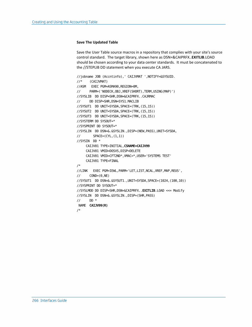
Creating and Using the Accounting Table
266 Interfaces Guide
Save The Updated Table
Save the User Table source macros in a repository that complies with your site's source control standard. The target library, shown here as DSN=&CAIPRFX..EXITLIB.LOAD should be chosen according to your data center standards. It must be concatenated to the //STEPLIB DD statement when you execute CA JARS.
//jobname JOB (Accntinfo),' CAIJVMAT ',NOTIFY=&SYSUID.
//* (CAIJVMAT)
//ASM EXEC PGM=ASMA90,REGION=0M,
// PARM=('NODECK,OBJ,XREF(SHORT),TERM,USING(MAP)')
//SYSLIB DD DISP=SHR,DSN=&CAIPRFX..CAJRMAC
// DD DISP=SHR,DSN=SYS1.MACLIB
//SYSUT1 DD UNIT=SYSDA,SPACE=(TRK,(15,15))
//SYSUT2 DD UNIT=SYSDA,SPACE=(TRK,(15,15))
//SYSUT3 DD UNIT=SYSDA,SPACE=(TRK,(15,15))
//SYSTERM DD SYSOUT=*
//SYSPRINT DD SYSOUT=*
//SYSLIN DD DSN=&.&SYSLIN.,DISP=(NEW,PASS),UNIT=SYSDA,
// SPACE=(CYL,(1,1))
//SYSIN DD *
CAIJV01 TYPE=INITIAL,CSNAME=CAIJV99
CAIJV01 VMID=DOSVS,DISP=DELETE
CAIJV01 VMID=CFT2ND*,VMAC=*,USER='SYSTEMS TEST'
CAIJV01 TYPE=FINAL
/*
//LINK EXEC PGM=IEWL,PARM='LET,LIST,NCAL,XREF,MAP,REUS',
// COND=(0,NE)
//SYSUT1 DD DSN=&.&SYSUT1.,UNIT=SYSDA,SPACE=(1024,(100,10))
//SYSPRINT DD SYSOUT=*
//SYSLMOD DD DISP=SHR,DSN=&CAIPRFX..EXITLIB.LOAD <<= Modify
//SYSLIN DD DSN=&.&SYSLIN.,DISP=(SHR,PASS)
// DD *
NAME CAIJV99(R)
/*

The Translate Component
Chapter 8: The VM Interface 267
The Translate Component
Translate Component Control Statements
VMPARM Statement
The VMPARM statement gives you runtime control of several variables in the VM Interface's translate component. Keywords and their values can be specified in any order. The statement identifier, VMPARM, must begin in position 2. This statement must be placed in the file defined by the //CAIJFIN DD of the CA JARS execution JCL. This statement is required.
Command Operands
VMPARM RECx -SNAP nnnn- -CNCT nnnn- -FBLK nnnn- -WORK nnnn-
x (in RECx)
(required) specifies the desired format of the output account record. O causes an OS formatted account record to be created. D causes a VSE formatted account record to be created. G causes creation of a VSE glossary record compatible with CA JARS RA for z/VSE period processing.
SNAP nnnn
specifies the count of rejected or invalid records to be SNAP dumped. If omitted, the VM Interface will SNAP the first 10 records encountered. To suppress this option, specify: SNAP 0.
CNCT nnnn
specifies the maximum number of days considered valid for the connect time in a single type 01 VM accounting record. If a record is encountered with a larger connect time, it is snapped and ignored. If omitted, the CNCT value defaults to 7 days.
FBLK nnnn
specifies the number of FBA blocks to be considered as one cylinder. This number is only used if your data center allocates temporary disk on FBA devices. If you do not specify an FBLK value, the VM Interface uses 1000.
WORK nnnn
For VSE users, this keyword specifies the number of SORTWKn files specified in your execution JCL.

Reporting Component
268 Interfaces Guide
UACTNAME Statement
When processing the translate component with a user accounting table, an additional control statement (UACTNAME) is required to name the generated user accounting table. The statement identifier, UACTNAME, must begin in position 2 and a space must precede the operand. This information is provided via the CAIJFIN DD statement. The format of this statement is as follows:
Statement Identifier Operand
UACTNAME name
UACTNAME
is the name of the command. It must be present, and spelled exactly as shown.
name
is the name given the User Accounting Table when it was placed in DSN=&CAIPRFX..EXITLIB.LOAD
Reporting Component
The VM Interface translate component creates summary file records in the same format as those produced by CA JARS z/OS to facilitate combined billing applications. VM account records, however, do not contain exactly the same information as accounting records produced by z/OS systems. Some fields in the VM Interface output record, therefore, do not have the same meaning as the corresponding fields in a record produced by CA JARS z/OS.
This guide contains a complete description of the records produced by the VM Interface. If you do not already use CA JARS for z/OS accounting, you can rely on this guide to interpret the data produced by the VM Interface. If you have some familiarity with CA JARS z/OS, note the following differences.
To interpret VM data, you must:
■ Use the VM Basic Accounting Table in this guide instead of the Basic Accounting Table in the User Guide.
■ Use the VM Output Data Elements Table in this guide instead of the Output Data Elements Table in the User Guide.
To apply billing rates to VM data in a CA JARS run, you must:
■ For CA JARS RA for z/OS, use the VMRATE statement described in this guide.
■ For CA JARS RA for z/VSE, use the CPURATE statement described in this guide.
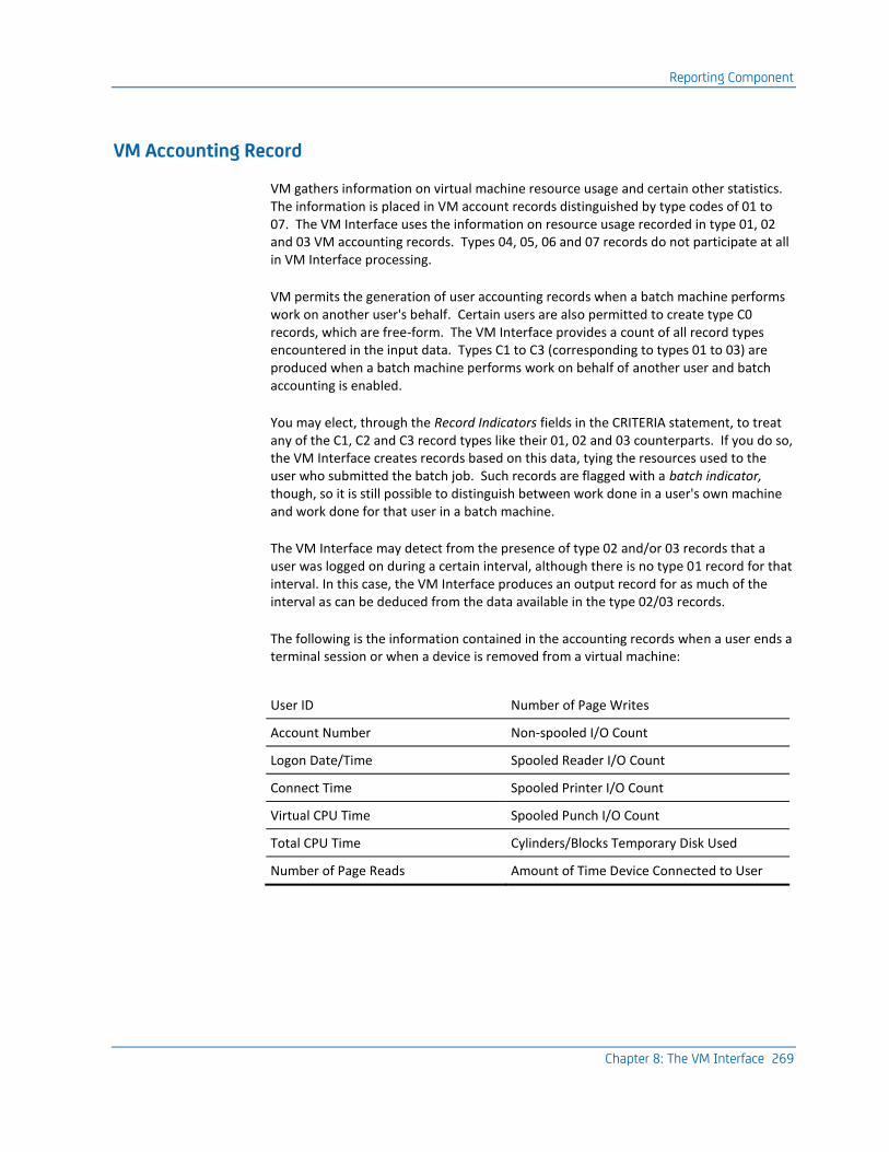
Reporting Component
Chapter 8: The VM Interface 269
VM Accounting Record
VM gathers information on virtual machine resource usage and certain other statistics. The information is placed in VM account records distinguished by type codes of 01 to 07. The VM Interface uses the information on resource usage recorded in type 01, 02 and 03 VM accounting records. Types 04, 05, 06 and 07 records do not participate at all in VM Interface processing.
VM permits the generation of user accounting records when a batch machine performs work on another user's behalf. Certain users are also permitted to create type C0 records, which are free-form. The VM Interface provides a count of all record types encountered in the input data. Types C1 to C3 (corresponding to types 01 to 03) are produced when a batch machine performs work on behalf of another user and batch accounting is enabled.
You may elect, through the Record Indicators fields in the CRITERIA statement, to treat any of the C1, C2 and C3 record types like their 01, 02 and 03 counterparts. If you do so, the VM Interface creates records based on this data, tying the resources used to the user who submitted the batch job. Such records are flagged with a batch indicator, though, so it is still possible to distinguish between work done in a user's own machine and work done for that user in a batch machine.
The VM Interface may detect from the presence of type 02 and/or 03 records that a user was logged on during a certain interval, although there is no type 01 record for that interval. In this case, the VM Interface produces an output record for as much of the interval as can be deduced from the data available in the type 02/03 records.
The following is the information contained in the accounting records when a user ends a terminal session or when a device is removed from a virtual machine:
User ID Number of Page Writes
Account Number Non-spooled I/O Count
Logon Date/Time Spooled Reader I/O Count
Connect Time Spooled Printer I/O Count
Virtual CPU Time Spooled Punch I/O Count
Total CPU Time Cylinders/Blocks Temporary Disk Used
Number of Page Reads Amount of Time Device Connected to User

Reporting Component
270 Interfaces Guide
User-Defined Reports
The output report formats vary from user to user, depending on the report control statements used. This section discusses features common to all user-defined reports. Refer to the report below for an example printout.
All user-defined reports formatted by the Report Writer contain three (3) parts:
■ header information
■ detail information
■ summary information
A --> V M T O T A L C H A R G E S U M M A R Y
B Y U S E R AND D A T E
BEGIN DATE - 01/14/97 <--B C --> RUN DATE - 02/01/94
END DATE - 01/22/97 <--D E --> PAGE 2
VM CONNECT PROCESS I/O U/R SETUP TOTAL PERCENT
USERID CHARGE CHARGE CHARGE CHARGE CHARGE CHARGE TOTAL
F-->DATE 970115 $10.54 $31.29 $90.47 $148.91 $5.00 $286.21 3.380
F-->DATE 970121 $26.18 $12.72 $514.60 $.00 $5.00 $558.50 6.595
USERID A42MAINT <-- G $36.72 $44.01 $605.07 $148.91 $10.00 $844.71 9.975
DATE 970118 $3.33 $.77 $.00 $.00 $.00 $4.10 .048
DATE 970121 $110.51 $6.31 $206.79 $12.53 $.00 $336.14 3.969
DATE 970122 $58.70 $.02 $117.45 $.00 $.00 $176.17 2.080
USERID CMSGXB $172.54 $7.10 $324.24 $12.53 $.00 $516.41 6.097
DATE 970118 $3.33 $.00 $.00 $.00 $.00 $3.33 .039
DATE 970121 $50.76 $44.78 $119.32 $4.86 $.00 $219.72 2.595
DATE 970122 $41.92 $27.64 $131.89 $26.14 $.00 $227.59 2.686 <--H
USERID CMSPLM $96.01 $72.42 $251.21 $31.00 $.00 $450.64 5.320 <--I
$2,680.06 $880.22 $4,523.90 $318.82 $65.00 $8,468.00 99.958 <--J
This report is described in detail on the next two pages.
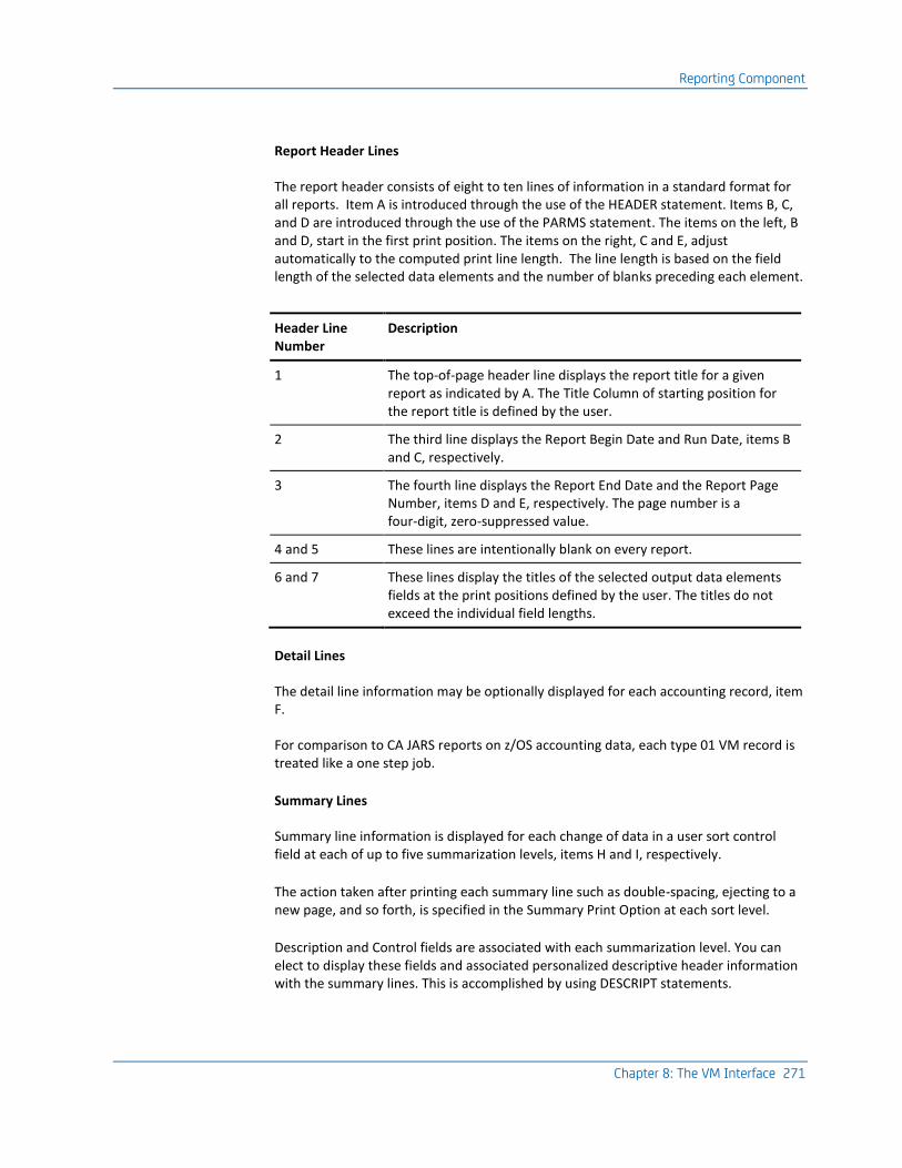
Reporting Component
Chapter 8: The VM Interface 271
Report Header Lines
The report header consists of eight to ten lines of information in a standard format for all reports. Item A is introduced through the use of the HEADER statement. Items B, C, and D are introduced through the use of the PARMS statement. The items on the left, B and D, start in the first print position. The items on the right, C and E, adjust automatically to the computed print line length. The line length is based on the field length of the selected data elements and the number of blanks preceding each element.
Header Line Number
Description
1 The top-of-page header line displays the report title for a given report as indicated by A. The Title Column of starting position for the report title is defined by the user.
2 The third line displays the Report Begin Date and Run Date, items B and C, respectively.
3 The fourth line displays the Report End Date and the Report Page Number, items D and E, respectively. The page number is a four-digit, zero-suppressed value.
4 and 5 These lines are intentionally blank on every report.
6 and 7 These lines display the titles of the selected output data elements fields at the print positions defined by the user. The titles do not exceed the individual field lengths.
Detail Lines
The detail line information may be optionally displayed for each accounting record, item F.
For comparison to CA JARS reports on z/OS accounting data, each type 01 VM record is treated like a one step job.
Summary Lines
Summary line information is displayed for each change of data in a user sort control field at each of up to five summarization levels, items H and I, respectively.
The action taken after printing each summary line such as double-spacing, ejecting to a new page, and so forth, is specified in the Summary Print Option at each sort level.
Description and Control fields are associated with each summarization level. You can elect to display these fields and associated personalized descriptive header information with the summary lines. This is accomplished by using DESCRIPT statements.
Reporting Component
272 Interfaces Guide
In addition, the Control field and Summarization Description can be displayed as headers to signal the beginning of a new summarization level as illustrated by item G. No other information appears on this line. Note that the descriptions have been staggered to present a more meaningful relationship between the different summarization levels. This is accomplished by appropriately spacing the Summarization Description in the field when preparing DESCRIPT statements.
An additional final summary line, item J, is automatically displayed at the end of each report. All information that can logically be accumulated is presented as a final total on this line. If page ejection has been specified for the highest (major) summarization level, this line will print on a separate page.
More information:
HEADER Statement (see page 295) DESCRIPT Statement (see page 279)
Preparing Control Statements
Control statements are used to tell the Report Writer which reports you want generated, for what time period, and how you want them formatted. They are contained in a file of fixed-length 80-byte records. Each control statement is identified by an eight-character alphanumeric statement type and checked for syntax and discrepancies that might cause errors during the run. If there are errors in the data, the record is flagged and a message is printed indicating the problem area.
Control statements are divided into two groups:
■ The first group consists of statements that govern the general aspects of the Report Writer run.
■ The second group controls the formatting of individual reports.
The following statements in the first group are required:
■ CONFIG statement
■ SELECT statement
The following statements in the first group are optional:
■ CRITERIA statement
■ PARMS statement
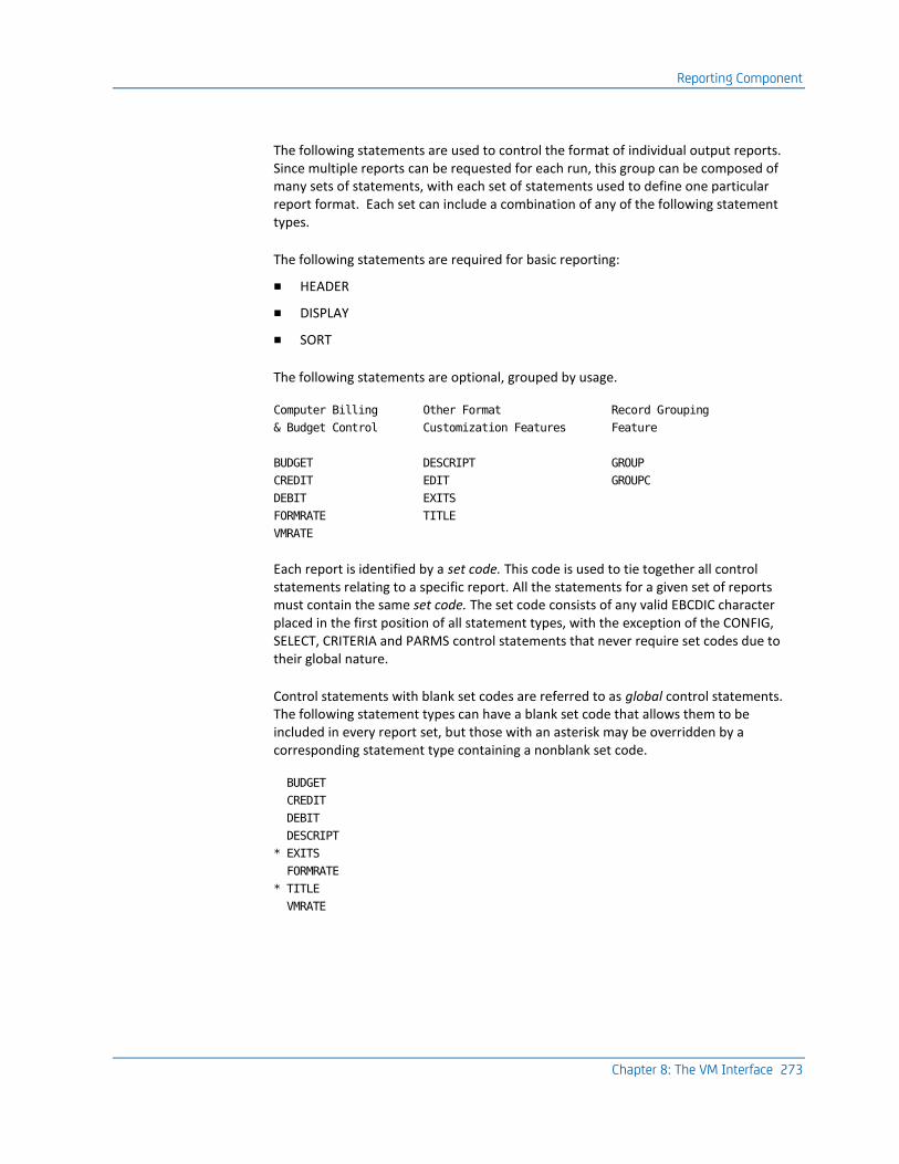
Reporting Component
Chapter 8: The VM Interface 273
The following statements are used to control the format of individual output reports. Since multiple reports can be requested for each run, this group can be composed of many sets of statements, with each set of statements used to define one particular report format. Each set can include a combination of any of the following statement types.
The following statements are required for basic reporting:
■ HEADER
■ DISPLAY
■ SORT
The following statements are optional, grouped by usage.
Computer Billing Other Format Record Grouping
& Budget Control Customization Features Feature
BUDGET DESCRIPT GROUP
CREDIT EDIT GROUPC
DEBIT EXITS
FORMRATE TITLE
VMRATE
Each report is identified by a set code. This code is used to tie together all control statements relating to a specific report. All the statements for a given set of reports must contain the same set code. The set code consists of any valid EBCDIC character placed in the first position of all statement types, with the exception of the CONFIG, SELECT, CRITERIA and PARMS control statements that never require set codes due to their global nature.
Control statements with blank set codes are referred to as global control statements. The following statement types can have a blank set code that allows them to be included in every report set, but those with an asterisk may be overridden by a corresponding statement type containing a nonblank set code.
BUDGET
CREDIT
DEBIT
DESCRIPT
* EXITS
FORMRATE
* TITLE
VMRATE

Reporting Component
274 Interfaces Guide
It is recommended that you include all sets of control statements when generating reports. Doing so assures that the Report Writer has access to all your user report formats, and relieves you of the necessity of combining the proper sets of control statements for the appropriate run. The SELECT statement is used to indicate which set(s) of statements are required to generate the desired report(s).
Control Statement Coding Conventions
All alphabetic characters entered on control statements are assumed to be uppercase by the editor. In general, all numeric fields are to be right justified and need not be padded with leading zeros, since the Report Writer performs this function as part of its numeric field editing routine. The input control statements are never sorted. Generally, the order of the statements is not important. However, in the case of certain statement types, order may have an effect on report results. Where such order is a consideration, it is noted in the detail description of the affected statement.
Caution Sequence numbers are unacceptable on control statements. The Report Writer interprets them as a function field.
CPU Identification Usage
Five report control statements allow you to specify a 1-byte field called CPU Identification: BUDGET, CREDIT, DEBIT, FORMRATE, and VMRATE. The CPU ID field is simply a 1-byte character field carried in every CA JARS record. When a nonblank character is placed in this field, it tells the Report Writer that the control statement applies only to those records having a matching CPU ID. However, a control statement with a blank CPU ID field applies to all records.
The CPU ID field is used primarily as a user controlled switch to separate different groups of data--it need not have anything to do with actual CPU Identification. There are two ways of setting this field:
■ Your User Accounting Table may set the CPU ID based on the VM userid and VM Account Number in the raw VM data.
■ The Report Writer Grouping feature, using the GROUP and GROUPC control statements, may set the CPU ID based on any test or series of tests expressible within the bounds of GROUP/GROUPC syntax.
Remember, the CPU ID field is provided as means for you to manipulate and separate data into convenient groups. A typical application is to separate data into groups according to the billing rates you plan to apply. You accomplish this by assigning different CPU IDs for each group on the VMRATE and FORMRATE statements. You can then charge different rates for each group based on their CPU ID.

Reporting Component
Chapter 8: The VM Interface 275
Report Control Statements
BUDGET Statement
Position Field Length
Field Name Notes
1 1 Set Code Optional
2-9 8 Statement Type BUDGET
10 1 CPU Identification
11-18 8 VM Account number
19-34 16 VM Account number or User Accounting Table information
35-40 6 Date YYMMDD
41-48 8 VM Userid
49-54 6 Time HHMMSS
55-74 20 Blanks
75-80 6 Budget Amount 999999V; dollars
This statement, identified by the statement type BUDGET, is optional. The BUDGET statement provides a mechanism by which you can manually introduce budget figures to the Report Writer and compare them to actual costs for a given period of time. Budget figures may be associated with a specific job or with any summarization level (account, department, project, and so forth).
Each BUDGET statement introduced to the Report Writer is formatted into an accounting record to be sorted and reported on as any other input. All BUDGET statement fields are moved into the corresponding fields in the accounting record. For processing purposes, the record is treated as a one-step job similar to those generated by CREDIT and DEBIT statements.
The Budget Amount, in dollars, is carried by the Report Writer and made available for display as DE ID 81 in the VM Output Data Elements Table.
The difference between the Budget Amount and the Total Charge (DE ID 46) can be displayed at any level as the Over-Under Budget figure, DE ID 82. The Percent Budget Spent, DE ID 83 can reflect what percent of the Budget Amount has been spent at any display level.

Reporting Component
276 Interfaces Guide
The following example illustrates a typical BUDGET statement setup:
position 75 x
ABUDGET 6 AAA 8409 125000
This BUDGET statement for Report A is to be applied against CPU Identification 6. The account number AAA, is assumed to be in the first three characters of the Accounting Fields information. The current September budget control report is to reflect a $125,000 budget for account AAA. Note that the Budget Amount field on the BUDGET statement is in dollars format with no cents.
CONFIG Statement
This statement, identified by the statement type CONFIG, is required. The CONFIG statement is used to define the computer installation's peripheral device configuration. It has meaning only when CA JARS reports on OS or VSE data. To satisfy the editing requirements, you should include a CONFIG statement of this form:
CONFIG READ00C
CREDIT Statement
Position Field Length
Field Name Notes
1 1 Set Code Optional
2-9 8 Statement Type CREDIT
10 1 CPU Identification
11-18 8 VM Account number
19-34 16 VM Account number or User Accounting Table information
35-40 6 Date YYMMDD
41-48 8 VM Userid
49-54 6 Time HHMMSS
55-74 20 Blanks
75-80 6 Credit Amount 9999V99; dollars

Reporting Component
Chapter 8: The VM Interface 277
This statement, identified by the statement type CREDIT, is optional. The CREDIT statement is used to supplement the accounting algorithm defined on the VMRATE and FORMRATE statements. Credits may be manually introduced to the Report Writer to be applied to a specific session or summarization level (account, department, project, and so forth). The CREDIT statement is typically used to:
■ negate job rerun costs
■ adjust prior months billing
■ provide volume processing discounts.
Each CREDIT statement introduced to the Report Writer is formatted into an accounting record to be sorted and reported on as any other input. All CREDIT statement fields are moved into the corresponding fields in the accounting record.
For processing purposes, the record is treated as a one-step job.
The following fields, if not present on the CREDIT statement, are filled with blanks in the formatted record:
■ CPU Identification
■ VM Account number
■ Account number/User Accounting Table information
■ VM Userid.
The following fields (or any portion thereof) not present on the CREDIT statement are filled with high values (hex 'FF') in the formatted record:
■ Date (YYMMDD)
■ Time (HHMMSS)
For collating purposes, note that the Date field is moved to the Start Date fields. Also, the Time field is moved to the Start Time fields in the formatted record. The high values portion of these fields, if any, do not print when selected for display and, therefore, can be used to reduce keypunch strokes when preparing CREDIT statements or to cause credits to collate last in a certain group of records.
The Credit Amount, in dollars, is carried by the Report Writer and made available for display as DE ID 79 in the VM Output Data Elements Table.
The Credit Amount also affects the Total Charge, Distributed Charge, and Percent Totals at any level of display (DE ID 46, 47, 41 and 42, respectively). The following is an example of a typical CREDIT statement setup:
position 75 x
ACREDIT 6 AAA 8408 150000
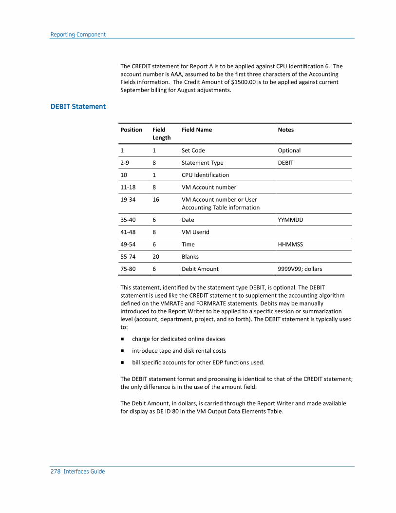
Reporting Component
278 Interfaces Guide
The CREDIT statement for Report A is to be applied against CPU Identification 6. The account number is AAA, assumed to be the first three characters of the Accounting Fields information. The Credit Amount of $1500.00 is to be applied against current September billing for August adjustments.
DEBIT Statement
Position Field Length
Field Name Notes
1 1 Set Code Optional
2-9 8 Statement Type DEBIT
10 1 CPU Identification
11-18 8 VM Account number
19-34 16 VM Account number or User Accounting Table information
35-40 6 Date YYMMDD
41-48 8 VM Userid
49-54 6 Time HHMMSS
55-74 20 Blanks
75-80 6 Debit Amount 9999V99; dollars
This statement, identified by the statement type DEBIT, is optional. The DEBIT statement is used like the CREDIT statement to supplement the accounting algorithm defined on the VMRATE and FORMRATE statements. Debits may be manually introduced to the Report Writer to be applied to a specific session or summarization level (account, department, project, and so forth). The DEBIT statement is typically used to:
■ charge for dedicated online devices
■ introduce tape and disk rental costs
■ bill specific accounts for other EDP functions used.
The DEBIT statement format and processing is identical to that of the CREDIT statement; the only difference is in the use of the amount field.
The Debit Amount, in dollars, is carried through the Report Writer and made available for display as DE ID 80 in the VM Output Data Elements Table.

Reporting Component
Chapter 8: The VM Interface 279
The Debit Amount also affects the Total Charge, Distributed Charge, and Percent Totals at any level of display (DE 46, 47, 41 and 42, respectively). The following are examples of typical DEBIT statement setups:
position 75 x
ADEBIT 6 AAA 9809 **DISK** 6000
ADEBIT 6 AAA 9809 **TAPE** 5000
ADEBIT 6 AAA 980915*BLOCK* 1330 22500
The first two DEBIT statements for Report A are to be applied against CPU Identification 6. The account number AAA, is assumed to be in the first three characters of the Accounting fields information. The current September billing is to include the Debit Amounts of $60.00 and $50.00, to be charged against account AAA for the rental of disks and tapes respectively.
The third DEBIT statement for Report A reflects a $225.00 charge against the same account for block time rental started at 13.30 on September 15, 1998. The debit can be associated with a particular VM userid by placing that userid in positions 41-48.
More information:
CREDIT Statement (see page 276)
DESCRIPT Statement
Position Field Length
Field Name Notes
1 1 Set Code Optional
2-9 8 Statement Type
DESCRIPT
10 1 Summarization Level
0 = any level 1 = 1st sort level (most general level) 2 = 2nd sort level 3 = 3rd sort level 4 = 4th sort level 5 = 5th sort level (most detailed level)

Reporting Component
280 Interfaces Guide
Position Field Length
Field Name Notes
11-18 8 Description Control Field
Matches Sort Control Field unless Variable Description feature is used. In that case:
Position Length Notes
11-14 4 **** asterisks
15-16 2 'TO' location in
DESCRIPT Field,
relative to 1
17 1 number of
characters
to be moved
18 1 'FROM' location
in Control Field,
relative to 1
(Refer to Variable Description feature)
19-38 20 Description Field
Refer to DE ID 02 in the Output Data Elements Table
39-80 42 Reserved Not used
This statement, identified by DESCRIPT, is optional. When selected, it provides a description of summary line information. Refer to DE ID 02 in the VM Output Data Elements Table.
The summarization level defines which sort control break the DESCRIPT statement refers to. For example, a user may select Product Name as the major sort control field. The Report Writer summarizes the accounting data and prints a summary line for all processing under each product and a final summary line for all products combined. To clarify the report, you can define a Summarization Description for each control break or summary line. In this example, the user might prepare the following set of DESCRIPT statements:
ADESCRIPT1DSM SCRIPT JOBS
ADESCRIPT1PROFS OFFICE MANAGEMENT
ADESCRIPT1JSIMAIN JARS REPORT RUNS
.
.
.
ADESCRIPT1 UNIDENTIFIED CLASS

Reporting Component
Chapter 8: The VM Interface 281
For a description of the user sort control fields, see page :spotref refid=vsort.. These sort control fields may be a maximum of eight characters in length. Unused characters are padded with trailing blanks. The Description Control Field must be the same as the 8-character sort control field. The description control field and a sort control field must match character for character to associate the correct description with the corresponding sort control break.
You may find that you require the same DESCRIPT statements for different report formats: the only variation is the summarization level. In one report the user might use product name as the level one sort control field, as in this example, and in another report use product name as a level 2 or 3 sort control field. The only difference in the two sets of DESCRIPT statements is the set code and the summarization level indicator.
You can however, leave the set code blank and define the summarization level as 0 this makes the summarization description available to all reports and to any control break, not just the level one break as in the example.
You must use the any level summarization level with caution. Certain reports, for example, one sorted by
level 1=department number
level 2=group number
level 3=employee number
In such cases, the user must specify summarization level to make sure that the right description appears at the right level.
Note: If fewer than five sort levels are used in a report, the user may identify them as:
1, 2, and 3;
2, 3, and 4; or even
1, 4, and 5.
Level numbers indicate relative positions; the precise number selected is only important because the level number on the DESCRIPT statement must match that defined on the SORT statement.
Variable Description Feature
You may find that at a particular sort level, there are a number of fields whose descriptions are almost the same except for a small amount of variable information. For example, at level 1 a report might sort through 20 or 25 Project IDs. In this case, rather than code a separate DESCRIPT statement for each control break or summary line, the user may prepare a single DESCRIPT statement and, by using the Variable Description feature, transfer the Project ID automatically from the sort control field into the description field. Refer to the SORT statement on :spotref refid=vsort..

Reporting Component
282 Interfaces Guide
You invoke this feature by replacing the first four characters of the Description Control Field with four asterisks. These indicate that the next four positions determine what is transferred from the Sort Control Field. The four asterisks are followed by:
2 characters indicating where the transferred data is placed in the Description field
1 character indicating how many characters of data to transfer
1 character indicating from which position in the Sort Control Field the transfer of the data is to begin.
The following example shows typical variable description usage:
Summarization Level
│
│ Invokes
│ Variable Description Feature
│ │
▼ ▼
┌────┐ ┌────────────────┐
ADESCRIPT1│****│ 0981 │PROJECT XXXXXXXX│
└────┘ └────────────────┘
▲
│
This will appear on every summary
line at this sort control level.
This statement defines the format for Report A. The summarization level is 1, followed by the four asterisks that invoke the Variable Description feature. The variable information (Project ID, in this case) located in the positions 1-8 of the sort control field, is transferred to the positions 9-16 of the description field (overlaying the xs appearing in the example).
Note that DESCRIPT statements using the variable description feature and those that contain blank description control fields share one characteristic; they terminate the DESCRIPT statement searching logic, and are used regardless of the current contents of the sort control field. DESCRIPT statements with blank description control fields are intended to be used for catchall or miscellaneous descriptions and should follow all DESCRIPT statements with nonblank description control fields.
DISPLAY Statement
Position Field Length Field Name Notes
1 1 Set Code Required
2 8 Statement Type DISPLAY
10-11 2 Title Table Suffix VO recommended for VM data

Reporting Component
Chapter 8: The VM Interface 283
Position Field Length Field Name Notes
12-80 3 . . . Up to 20 additional occurrences . .
Output Data Element Selection Table
1 to 23 occurrences of lnn where:
l: = Number of leading spaces (0-9)
nn:= Output Data Element ID (01-H3)
Refer to VM Data Elements Table
This statement, identified by the statement type DISPLAY, is required. The DISPLAY statement lets you select the desired data elements for display and define the print line format.
The Output Data Element Selection Table allows you to select as many as 23 data elements from a pool of available elements to display in a given report. The table entries are in the format lnn where,
l
is a one-digit number of leading spaces.
nn
is a two-character code identifying the data element selected for display.
This identification corresponds to the DE ID in the Output Data Elements Table. See the VM Output Data Elements Table starting later in this chapter.
Each DISPLAY statement must have a set code.
The following example illustrates a typical DISPLAY statement:
ADISPLAY V0002101504106512113129142146147
This DISPLAY statement defines the format for Report A as indicated by the set code in statement position 1. The data elements selected, in order, are:
■ Description Field
■ Control Field
■ User ID
■ Start Date
■ Start Time
■ Stop Time
■ Processor Time
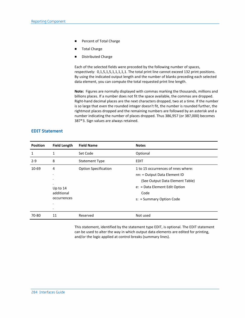
Reporting Component
284 Interfaces Guide
■ Percent of Total Charge
■ Total Charge
■ Distributed Charge
Each of the selected fields were preceded by the following number of spaces, respectively: 0,1,5,1,5,1,1,1,1,1. The total print line cannot exceed 132 print positions. By using the indicated output length and the number of blanks preceding each selected data element, you can compute the total requested print line length.
Note: Figures are normally displayed with commas marking the thousands, millions and billions places. If a number does not fit the space available, the commas are dropped. Right-hand decimal places are the next characters dropped, two at a time. If the number is so large that even the rounded integer doesn't fit, the number is rounded further, the rightmost places dropped and the remaining numbers are followed by an asterisk and a number indicating the number of places dropped. Thus 386,957 (or 387,000) becomes 387*3. Sign values are always retained.
EDIT Statement
Position Field Length Field Name Notes
1 1 Set Code Optional
2-9 8 Statement Type EDIT
10-69 4 . . . Up to 14 additional occurrences . .
Option Specification 1 to 15 occurrences of nnes where:
nn: = Output Data Element ID
(See Output Data Element Table)
e: = Data Element Edit Option
Code
s: = Summary Option Code
70-80 11 Reserved Not used
This statement, identified by the statement type EDIT, is optional. The EDIT statement can be used to alter the way in which output data elements are edited for printing, and/or the logic applied at control breaks (summary lines).

Reporting Component
Chapter 8: The VM Interface 285
Alternate edit and/or summary option codes may be specified for up to 15 output data elements. The available edit option codes and their interpretations are described in the following Data Element Edit Option Codes Table. The available summary option codes and their interpretations are described in the Summary Option Codes Table. The specification of an edit or summary option that is not applicable to a particular type of output data element is ignored, and the default options are used. One EDIT statement can be used globally, that is with a blank set code. This statement can be overridden for any individual report by an EDIT statement with a nonblank set code. The relative order of the statements in the input stream has no effect on this logic.
Only one edit and summary option can be in effect for an output data element even if it is specified more than once on either a DISPLAY or EDIT statement. If specified more than once on an EDIT statement, the last (rightmost) set of options apply. An exception to this is the use of the S (Sign) or E (Currency Symbol), which are additive, and may be specified in addition to a formatting type edit option.
The calculation of utilization rate and index data elements are handled as special cases by the Report Writer and the specification of alternate summary options for these types of output data elements is not recommended. If this is done, the summary option is applied to the calculated value contained in the Basic Account Record. For example, if a summary option of T is specified for the Output Data Element 78 (I/O Index), the result at each control break is the display of the total of all calculated I/O Index values from each Basic Account Record within that control break. It is unlikely that this particular number would be of much interest, but there may well be valid applications for the use of the minimum, maximum or average type summary options with these types of output data elements. Since the effect of several of the summary options is to significantly alter the interpretation of the displayed data elements, it is suggested that appropriate titles also be specified.
Data Element Edit Option Codes
Option Code Description Code
0 Edit numbers as integers (that is, zero decimal positions)
1 Edit numbers with one decimal place
2 Edit numbers with two decimal places
3 Edit numbers with three decimal places
4 Edit numbers with four decimal places
5 Edit numbers with five decimal places
H Edit time fields at HHHH.MM.SS or HHHHHHH.MM
D Edit dates as DD/MM/YY
M Edit dates as MM/DD/YY
Y Edit dates as YY/MM/DD

Reporting Component
286 Interfaces Guide
Option Code Description Code
C Edit character data - normal default for most non-numeric data elements
S Reserve low-order position for sign: =positive, - = negative*
E Add currency symbol if space is available and not suppressed via PARMS statement*
Do not change - allow default option to remain in effect
* May be used in combination with other option specifications for the same output data element.
Summary Option Codes
Summary Option Code Table:
Option Code Note Description
T TOTAL - Normal default for most numeric Output date
A AVERAGE - Total divided by number of records
H 2 HIGHEST value encountered since last Control break
L 2 LOWEST value encountered since last Control break
D 2 DISPLAY edited value from last Account Record before a Control break
N 2 NO-OP - Do not display anything - default for character fields
B 3 BREAK-AVERAGE - Total divided by number of control field changes at next lower summary level
U 1 USER-AVERAGE - Total divided by accumulation of User-Count-Field
I 1 INDEX - Total divided by accumulation of CPU Time (in seconds)
E 1 ELAPSED-INDEX - Total divided by accumulation of Elapsed-Time (in minutes)
Do not change - Allow default option to remain in effect

Reporting Component
Chapter 8: The VM Interface 287
Option Code Note Description
Note:
■ Operative at detail level, as well as each summary level.
■ Only options allowable for non-numeric data-elements, thatinclude dates and times-of-day.
■ Example: Sort Field 1 = Userid, Sort Field 2 = Run Date: Result at second summary level is daily total, at first summary level is average per day, at grand total is average per different userid. See references to Output Data Element F7: Control Break Count.
EXITS Statement
Position Field Length
Field Name Notes
1 1 Set Code
2-9 8 Card Type EXITS
10-17 8 Exit Name #1 Before Calculation of Charges = no exit
18-25 8 Exit Name #2 After Calculation of Charges xxxxxxxx = member or alias name
26-33 8 Exit Name #3 Output Phase
34-80 39 Reserved Not used
This statement, identified by the statement type EXITS, is optional. Its presence tells the Report Writer that you will use at least one exit at various phases during processing. Three exits allow you to edit, modify, and delete accounting information in the reporting phase. Details regarding these exits are discussed in the User Exit Routines section of this chapter.
The set code for the EXITS statement can be left blank; however, such a statement is overridden if the Report Writer encounters an EXITS statement with a nonblank set code.
If an Exit Name field on the EXITS statement is omitted, no exit is taken. A nonblank field sets up the exit and must be the one to eight-character load module name of the user-coded exit routine to be accessed. An exit program must be available to the Report Writer as a member of a z/OS or VSE executable library.

Reporting Component
288 Interfaces Guide
The Load Library containing the EXIT modules can be any z/OS PDS. If you choose to use &CAIPRFX..CAJRLOAD, be sure not to replace a member supplied by CA. If you prefer a user exit library, concatenate it to the //STEPLIB DD statement.
FORMRATE Statement
Position Field Length
Field Name Notes
1 1 Set Code Optional
2-9 8 Statement Type FORMRATE
10 1 CPU Identification
11 1 Reserved Not used
12-15 4 Forms ID Blanks
16-19 4 Setup Charge 99V99; dollars
20-23 4 Line/Card Rate 99V99; dollars per 1000
24-80 57 Reserved Not used
This statement, identified by the statement type FORMRATE, is optional.
The number you enter in the Line/Card Rate field (positions 20-23) is your charge per 1000 lines sent to a virtual printer.
GROUP Statement
Position Field Length
Field Name Notes
1 1 Set Code Required
2-9 8 Statement Type GROUP

Reporting Component
Chapter 8: The VM Interface 289
Position Field Length
Field Name Notes
10-15
16-21
22-27
28-33
34-39
40-45
6
6
6
6
6
6
Group 1 Definition Group 2 Definition Group 3 Definition Group 4 Definition Group 5 Definition Group 6 Definition
where: ppplfi
ppp: beginning portion of
selected field*
l: length of selected field
(maximum of 8)
f: format of selected field
: character
p: packed decimal
X: hexadecimal (binary)
i: Selection Indicator
: select all records
S: select qualified records
R: reject qualified records
46-80 35 Reserved Not used
Selected Field Length cannot be greater than 4 if either P or X is used as Format Indicator.
* Refer to the VM Basic Accounting Table
This statement, identified by the statement type GROUP, is optional. The GROUP statement in conjunction with GROUPC statements provides you with a mechanism to identify or qualify accounting records based on values in defined positions of the record. Once an accounting record has been qualified, the following functions can be employed at your option:
■ select or reject the record for further processing
■ assign the record a unique group code that can subsequently be used as a sort control field
■ assign the record a unique CPU Identification code in order that a specific billing algorithm can be applied

Reporting Component
290 Interfaces Guide
The Grouping feature can be used to:
■ expand criteria base for record selection/rejection
■ summarize records that do not have common characteristics
■ apply different billing algorithms to selected accounts
■ report on and charge users according to shift differentials
Six different levels of tests can be defined on the GROUP statement in the format ppplfi, where:
ppp
is a three-digit number defining the starting position (character) in the Basic Accounting Table used to set up a qualifier for the grouping feature.
l
is a one-digit number defining the number of characters (beginning with and including the starting position) in the Basic Accounting Table used to construct the length of the qualifier for the grouping feature.
f
is a one-character code indicating the data format of the field in the Basic Accounting Table being used as the qualifier for the grouping feature.
A blank format indicator is used for EBCDIC, a P for packed decimal, and an X for binary or the hexadecimal portion of a packed decimal field.
i
is a one-character code indicating whether qualified records should be selected or rejected.
An S causes all identified record groups to be selected for further processing and all unidentified record groups to be automatically rejected. An R causes the reverse effect to allow the user to reject identified record groups.
If the indicator is left blank, no record rejection occurs and all record groups are selected for further processing. This is particularly useful when all records are to be grouped for display purposes without dropping any information, as in computer time shift reporting.
The process of identifying records starts with the Group One Definition. If the record is qualified and selected, the process continues to the Group Two Definition and so on to the Group Six Definition in a similar manner. If a record is selected based on all definitions, then the record is considered selected for further processing. If a record is rejected based on any single definition, then the record is considered rejected from further processing.

Reporting Component
Chapter 8: The VM Interface 291
GROUPC Statement
Position Field Length
Field Name Notes
1 1 Set Code Required
2-9 8 Statement Type GROUPC
10 1 Definition Indicator
1 to 6; relates to a Group Definition on the Group statement
11-18 8 Lower Limiting Criteria*
19-26 8 Upper Limiting Criteria*
Optional if same as lower limit
27 1 Group Code Any character; to be placed in appropriate Group Code field in accounting record
28 1 CPU Identification any character = replace CPU ID in accounting record with this character
29-80 52 Reserved Not used
Each Criteria Field is converted to packed-decimal or hexadecimal (binary) or left as is depending on the contents of the appropriate Format Indicator in the GROUP statement.
Refer to the table below to determine the number of characters to code in the Criteria fields (always left justified for Format Indicators P and X):
GROUP Statement Number of Characters for:
Field Length P X
1 1 2
2 3 4
3 5 6
4 7 8
This statement, identified by the statement type GROUPC, is optional. The GROUPC statement must be used in conjunction with the GROUP statement for a given report. Whereas the GROUP statement defines which fields in the accounting record are to be used in the grouping feature, the GROUPC statement supplies the range of values to be used in a compare instruction to qualify the record. Multiple GROUPC statements may be required for a given report in order to provide many value ranges to qualify each accounting record.

Reporting Component
292 Interfaces Guide
The Definition Indicator on the GROUPC statement indicates which definition of the GROUP statement is applicable. Therefore, the Definition Indicator may be 1 to 6, relating to the proper definition number on the GROUP statement.
The Lower and Upper Limiting Criteria on the GROUPC statement provide the actual range of values that are compared against the corresponding value in the accounting record to qualify the record.
The range values must be left justified with trailing blanks when needed. If the Upper Limiting Criteria is the same as the Lower Limiting Criteria, it can be omitted.
The Group Code on the GROUPC statement is a one-character code that is placed in any accounting record that is selected according to the value ranges. The Group Code can subsequently be used as a sort control field via the SORT statement to provide totals for the different groups of accounting records selected by the grouping feature.
Note that positions 296 through 298 and positions 438 through 440 in the Basic Accounting Table correspond to the Group Codes for the six definitions as defined by the Definition Indicator on the GROUPC statement.
The CPU Identification code on the GROUPC statement allows you to dynamically change the CPU Identification of any accounting record for further processing. In this way, qualified records can be assigned different CPU Identification codes corresponding to multiple VMRATE statements for a given report. Identified record groups may then use a different accounting algorithm than other accounting records.
A blank CPU Identification Code on the GROUPC statement indicates that no change in the record CPU Identification is desired.
The examples on the following page show some typical uses and combinations of the GROUP and GROUPC statements.

Reporting Component
Chapter 8: The VM Interface 293
Grouping Feature Example 1
Request
Report utilization by shifts where:
shift A = 8 am - 4 pm
shift B = 4 pm - 12 pm
shift C = 12 pm - 8 am
1. Build GROUP and GROUPC statements as follows:
points to hours position of Start Time field in VM Basic Accounting Table:
select all records
V
AGROUP 0102
AGROUPC 108 15 A Shift A
AGROUPC 116 23 B Shift B
AGROUPC 100 07 C Shift C
2. Build SORT statement to sort on Group #1 Code field in accounting record.
3. DESCRIPT statements could then be used to associate Group Codes with literals as follows:
ADESCRIPT0A FIRST SHIFT
ADESCRIPT0B SECOND SHIFT
ADESCRIPT0C THIRD SHIFT
Example 1 shows you how to use the grouping feature without employing the record selection/rejection option. All records have been selected and assigned a Group Code according to which range the Start Time corresponds. The appropriate Group Code (A, B, or C) is placed in the Group #1 Code field in each record and subsequently used as a sort control field to produce totals for the three shifts.
Grouping Feature Example 2
Request
A report of CMS batch work run between 8 a.m. and 12 noon on Mondays ONLY, during the first quarter of 1994.
1. Build CRITERIA statement to select 01/01/94 through 03/31/94.
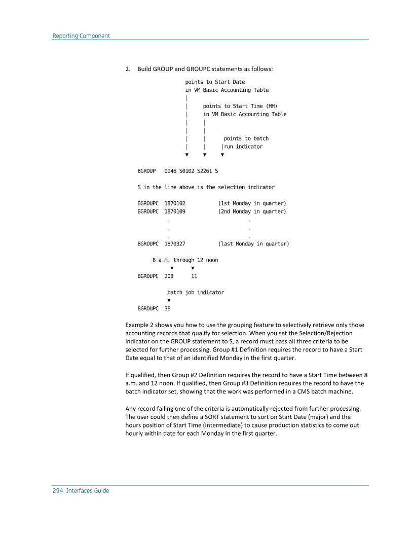
Reporting Component
294 Interfaces Guide
2. Build GROUP and GROUPC statements as follows:
points to Start Date
in VM Basic Accounting Table
│
│ points to Start Time (HH)
│ in VM Basic Accounting Table
│ │
│ │
│ │ points to batch
│ │ │run indicator
▼ ▼ ▼
BGROUP 0046 S0102 S2261 S
S in the line above is the selection indicator
BGROUPC 1870102 (1st Monday in quarter)
BGROUPC 1870109 (2nd Monday in quarter)
. .
. .
. .
BGROUPC 1870327 (last Monday in quarter)
8 a.m. through 12 noon
▼ ▼
BGROUPC 208 11
batch job indicator
▼
BGROUPC 3B
Example 2 shows you how to use the grouping feature to selectively retrieve only those accounting records that qualify for selection. When you set the Selection/Rejection indicator on the GROUP statement to S, a record must pass all three criteria to be selected for further processing. Group #1 Definition requires the record to have a Start Date equal to that of an identified Monday in the first quarter.
If qualified, then Group #2 Definition requires the record to have a Start Time between 8 a.m. and 12 noon. If qualified, then Group #3 Definition requires the record to have the batch indicator set, showing that the work was performed in a CMS batch machine.
Any record failing one of the criteria is automatically rejected from further processing. The user could then define a SORT statement to sort on Start Date (major) and the hours position of Start Time (intermediate) to cause production statistics to come out hourly within date for each Monday in the first quarter.
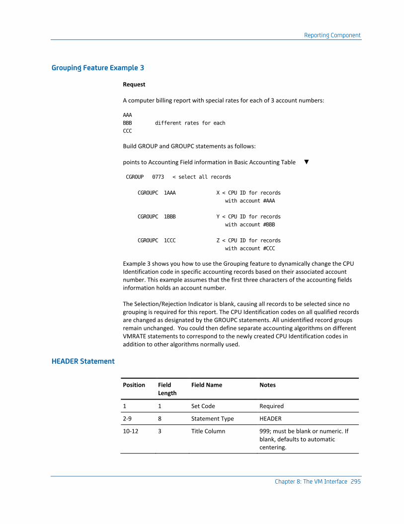
Reporting Component
Chapter 8: The VM Interface 295
Grouping Feature Example 3
Request
A computer billing report with special rates for each of 3 account numbers:
AAA
BBB different rates for each
CCC
Build GROUP and GROUPC statements as follows:
points to Accounting Field information in Basic Accounting Table ▼
CGROUP 0773 < select all records
CGROUPC 1AAA X < CPU ID for records
with account #AAA
CGROUPC 1BBB Y < CPU ID for records
with account #BBB
CGROUPC 1CCC Z < CPU ID for records
with account #CCC
Example 3 shows you how to use the Grouping feature to dynamically change the CPU Identification code in specific accounting records based on their associated account number. This example assumes that the first three characters of the accounting fields information holds an account number.
The Selection/Rejection Indicator is blank, causing all records to be selected since no grouping is required for this report. The CPU Identification codes on all qualified records are changed as designated by the GROUPC statements. All unidentified record groups remain unchanged. You could then define separate accounting algorithms on different VMRATE statements to correspond to the newly created CPU Identification codes in addition to other algorithms normally used.
HEADER Statement
Position Field Length
Field Name Notes
1 1 Set Code Required
2-9 8 Statement Type HEADER
10-12 3 Title Column 999; must be blank or numeric. If blank, defaults to automatic centering.
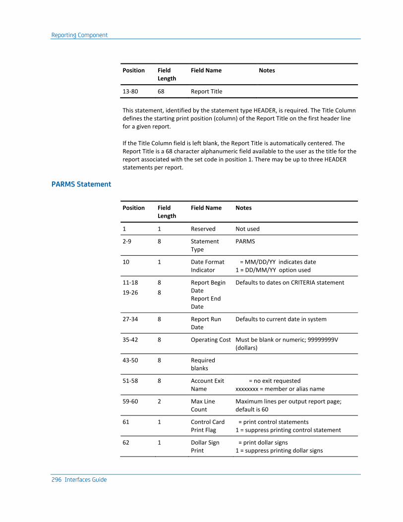
Reporting Component
296 Interfaces Guide
Position Field Length
Field Name Notes
13-80 68 Report Title
This statement, identified by the statement type HEADER, is required. The Title Column defines the starting print position (column) of the Report Title on the first header line for a given report.
If the Title Column field is left blank, the Report Title is automatically centered. The Report Title is a 68 character alphanumeric field available to the user as the title for the report associated with the set code in position 1. There may be up to three HEADER statements per report.
PARMS Statement
Position Field Length
Field Name Notes
1 1 Reserved Not used
2-9 8 Statement Type
PARMS
10 1 Date Format Indicator
= MM/DD/YY indicates date 1 = DD/MM/YY option used
11-18
19-26
8
8
Report Begin Date Report End Date
Defaults to dates on CRITERIA statement
27-34 8 Report Run Date
Defaults to current date in system
35-42 8 Operating Cost Must be blank or numeric; 99999999V (dollars)
43-50 8 Required blanks
51-58 8 Account Exit Name
= no exit requested xxxxxxxx = member or alias name
59-60 2 Max Line Count
Maximum lines per output report page; default is 60
61 1 Control Card Print Flag
= print control statements 1 = suppress printing control statement
62 1 Dollar Sign Print
= print dollar signs 1 = suppress printing dollar signs

Reporting Component
Chapter 8: The VM Interface 297
Position Field Length
Field Name Notes
63 1 Reserved Not used
64-66 3 Sort Core Size Core size for sort in K bytes; default is 64K; at least 128k is recommended when running under CMS
67 1 Reserved Not used
68 1 Sort Message Indicator
= print CRITICAL messages only 1 = print ALL messages
69-80 12 Reserved Not used
This statement, identified by the statement type PARMS, is optional. The PARMS statement provides a means to specify optional parameters to the Report Writer during execution.
The date format indicator defines the date format on all report control statements. The three date fields on the PARMS statement are used as the header dates for all reports generated in a given run. The date fields are alphanumeric and will not be edited by the Report Writer. They have no relationship to the selection or rejection of input accounting records. This function is controlled by the CRITERIA statement.
If omitted, the Report Begin Date defaults to the lower limit date criteria as defined on the CRITERIA statement (if present). Similarly, the Report End Date assumes the upper limit date criteria value on the CRITERIA statement. In the absence of a CRITERIA statement, the begin and end dates will be filled by the earliest and latest input record dates encountered. If omitted, the Report Run Date is filled with the current system date.
Nonblank date fields on the PARMS statement override the defaults and are moved to their respective positions in the heading information for each report generated in a given run.
The operating cost field may be used to introduce the total EDP cost for an installation for a given time period. This value is then used to compute the distributed charge amount available for display by the user. For example, if the total EDP cost for an installation is $60,000 for a given period of time, then all computer users for that period should theoretically account for this amount on a pro rata basis. If a certain customer or inhouse department used 10 percent of the total computer effort, then they should account for $6,000 toward the EDP budget. Note that this is the distributed charge based on resources used versus the EDP cost, not the total charge based on resources used versus a billing algorithm.
The account exit name is an eight-character field identifying an exit routine to be given control each time a record is about to be written to the account file. For details regarding exit routines, see the User Exit Routines section of this chapter.

Reporting Component
298 Interfaces Guide
The max line count field can be used to adjust the maximum number of lines to be printed per page of output. A two-digit numeric value overrides the default value of 60 lines per page.
The control card print flag can be used to suppress the printing of report level control statements. This feature is provided so that production runs that use many user-supplied statements do not have to list the control statements.
The dollar sign print flag provides you with the option of producing financial reports with or without the dollar sign ($) appearing in charge related output data elements. This is particularly useful for installations using a print chain with a limited number of dollar sign characters. The print rate can be increased considerably by avoiding the printing of special characters. The default is to force the use of dollar signs where appropriate.
The sort core size field can be used to define to the Report Writer the amount of main storage to be used by the sorting operation. A three-digit numeric value represents the amount of storage in 1K byte increments that overrides the default value of 64K.
The sort message indicator can be used to cause the sort/merge program to display messages to the printer via the parameter MSG=AP. The default for this parameter is MSG=CP, specifying that only critical messages are to be printed.
SELECT Statement
Position Field Length Field Name Notes
1 1 Reserved Not used
2-9 8 Statement Type SELECT
Input Indicators:
10-13 4 Required Blanks
14 1 Account Input = no input required
15 1 History Input 1 = input required
16 1 No Input Indicator 1 = process from an existing account file
17 1 Edit Only 1 = edit all control statements but do not process and input
18-50 33 Required blanks
User-Defined Reports Selection Indicators:
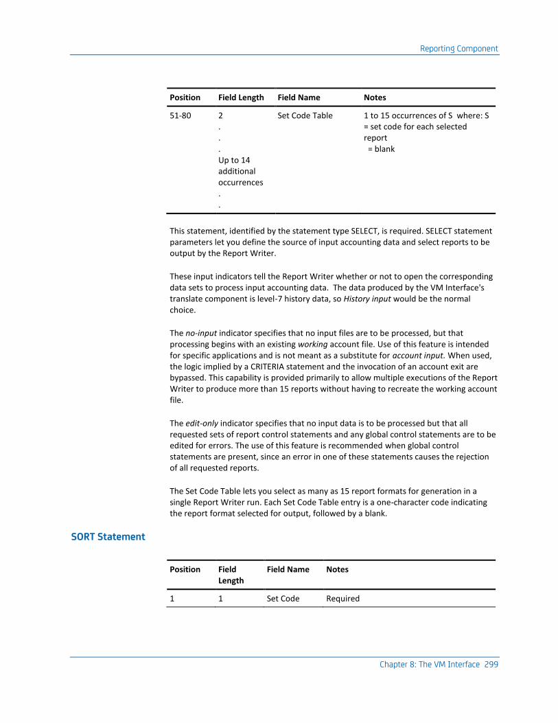
Reporting Component
Chapter 8: The VM Interface 299
Position Field Length Field Name Notes
51-80 2 . . . Up to 14 additional occurrences . .
Set Code Table 1 to 15 occurrences of S where: S = set code for each selected report = blank
This statement, identified by the statement type SELECT, is required. SELECT statement parameters let you define the source of input accounting data and select reports to be output by the Report Writer.
These input indicators tell the Report Writer whether or not to open the corresponding data sets to process input accounting data. The data produced by the VM Interface's translate component is level-7 history data, so History input would be the normal choice.
The no-input indicator specifies that no input files are to be processed, but that processing begins with an existing working account file. Use of this feature is intended for specific applications and is not meant as a substitute for account input. When used, the logic implied by a CRITERIA statement and the invocation of an account exit are bypassed. This capability is provided primarily to allow multiple executions of the Report Writer to produce more than 15 reports without having to recreate the working account file.
The edit-only indicator specifies that no input data is to be processed but that all requested sets of report control statements and any global control statements are to be edited for errors. The use of this feature is recommended when global control statements are present, since an error in one of these statements causes the rejection of all requested reports.
The Set Code Table lets you select as many as 15 report formats for generation in a single Report Writer run. Each Set Code Table entry is a one-character code indicating the report format selected for output, followed by a blank.
SORT Statement
Position Field Length
Field Name Notes
1 1 Set Code Required

Reporting Component
300 Interfaces Guide
Position Field Length
Field Name Notes
2-9 8 Statement Type
SORT
10-17 18-25 26-33 34-41 42-49
8 8 8 8 8
1st Sort Level 2nd Sort Level 3rd Sort Level 4th Sort Level 5th Sort Level
pppllosd must be blank or numeric where:
ppp: Position of sort field from
VM Basic Accounting Table
ll: Length of sort field
(maximum is 8)
o: Order of sort field
A = ascending (default)
D = descending
s: Summary Line Print Option:
see table below
d: Description Header Flag:
= suppress printing
1 = print Description Header
for this level
50 1 Job Flag 1 required for VM processing
51-54 4 Required blanks
55-62 8 History File DDname
= No History File xxxxxxxx = History File DDname
63 1 History Level Flag
1-5 = Summary level history file with charges applied
64 1 Print DDname Suffix
If nonblank, append to DDname of CAIJSPRT and use that DDname for the report output
65-80 16 Reserved Not used
Summary Line Print Option Table
or N - No summary print for this level 1, 2, or 3 - Single, double, or triple space before printing summary E* - Eject to new page after printing summary P* - Eject to new page and reset page number after printing summary
* If either E or P is specified for the first level summary line, then grand totals print on a page by themselves.

Reporting Component
Chapter 8: The VM Interface 301
The SORT statement, identified by the statement Type SORT, is required. It allows the input accounting data to be sorted on up to five different fields. Each field or sort level is defined by the format pppllosd where:
ppp
is a three-digit number indicating the sort field's starting position. Refer to the VM Basic Accounting Table later in this chapter.
ll
is a two-digit number between 01 and 08 defining the length of the sort field in the VM Basic Accounting Table.
o
indicates the sort order:
A =
ascending (default)
D =
descending
s
is the summary print option that tells the Report Writer whether the user wants a summary line printed for this level and is defined as follows:
N or =
no summary line is printed at this level.
1, 2, or 3 =
single, double, or triple spacing before printing the summary line.
E =
eject to a new page after printing summary.
P =
eject to new page and reset page number to 1 after printing. (If either E or P is specified for the first [major] summary level, grand totals print on a page by themselves.)
d
indicates whether a Descriptive Header appears at this level.
The creation of any user sort control field may be omitted. If no sort control field is specified, the accounting data is arranged in the following default order:
■ Start Date
■ Start Time.
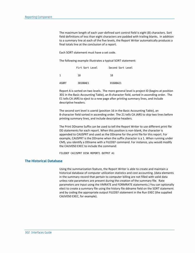
Reporting Component
302 Interfaces Guide
The maximum length of each user-defined sort control field is eight (8) characters. Sort field definitions of less than eight characters are padded with trailing blanks. In addition to a summary line at each of the five levels, the Report Writer automatically produces a final totals line at the conclusion of a report.
Each SORT statement must have a set code.
The following example illustrates a typical SORT statement:
Firt Sort Level Second Sort Level
1 10 18
ASORT 30108AE1 01608A21
Report A is sorted on two levels. The more general level is project ID (begins at position 301 in the Basic Accounting Table), an 8-character field, sorted in ascending order. The E1 tells CA JARS to eject to a new page after printing summary lines, and include descriptive headers.
The second sort level is userid (position 16 in the Basic Accounting Table), an 8-character field sorted in ascending order. The 21 tells CA JARS to skip two lines before printing summary lines, and include descriptive headers.
The Print DDname Suffix can be used to tell the Report Writer to use different print file DD statements for each report. When this position is non-blank, the character is appended to CAIJSPRT and used as the DDname for the print file for this report. For example, CAIJSPRT is the DDname when the suffix character is a 1. When running under CMS, you identify a DDname with a FILEDEF command. For instance, you would modify the CAIJV050 EXEC to include the command:
FILEDEF CAIJSPRT DISK REPORT1 OUTPUT A1
The Historical Database
Using the summarization feature, the Report Writer is able to create and maintain a historical database of computer utilization statistics and cost accounting. (data elements in the summary record that pertain to computer billing are not filled with valid data unless rate parameters are present during the creation of the summary file. Rate parameters are input using the VMRATE and FORMRATE statements.) You can optionally elect to create a summary file using the history file ddname field on the SORT statement and by coding the appropriate output FILEDEF statement in the Run EXEC (the supplied CAIJV050 EXEC, for example).
Reporting Component
Chapter 8: The VM Interface 303
You can further specify to what level of detail the summary file is created using the summary flag on the SORT statement. The summary flag, that you define, allows summarization at any of 7 levels. Levels 1-5 correspond to sort fields in your SORT statement. Levels 6 and 7 correspond to the OS concepts of job level and step level. The output of the VM Interface's translate component (input to the Report Writer generator) is a level-7 history file. There is no advantage to creating a level-6 file from VM data. If you apply rates to your data, to calculate changes, you may wish to create a level-7 output file, since the output records include the charge amounts. Level 1-5 output is perfectly logical for VM data. Such a file would represent your data summarized at the sort level you select. The following FILEDEF statement reflects a typical method of retaining this file:
FILEDEF HISTOUT DISK AUG94 BYDATE A4 ( RECFM VB LRECL 8188 BLKSIZE 8192
The summary file can be subsequently introduced to the Report Writer using the history input indicator.
History Files
The history file name indicates that the user wants to build an output file with the report. There are two kinds of history files:
The first kind is the detail level history file. It is an archive or database of all accounting information (not just the information output on the report being created.) The output of the VM Interface's translate component is a detail level history file. It includes all the data in the raw VM accounting data, but no dollar charges (since rates are not supplied to the translate component). If you wish to preserve the charges you apply with VMRATE and/or FORMRATE statements, you may create a detail level history file as output from the report writer. This file may be used as input for future reports.
The second type of history file is a summary level history file that creates an output file of summary line information. It is useful for creating subsequent periodic or year-to-date reports with little effort. The summary level history file can be created at any sort level from 1 to 5. Note that a level-3 summary file, for example, also contains information that may be summarized mathematically for sort levels 1 and 2.
The history level flag defines the kind of history file to be created and at which level. A level 1-5 flag refers to the corresponding sort control level for a summary level history file. Requesting a level-7 (detail level) history file causes the report writer to produce an output history file that includes any charges you have applied. This output file is otherwise the same as the file produced by the translate program.

Reporting Component
304 Interfaces Guide
Summary Level History File Example
The following example illustrates how to create a summary level history file:
Points to Start Date in Basic Accounting Table │ │ Points to Account Number │ ┌────── Points to Start Time in in Basic Accounting Table │ │ Basic Accounting Table │ │ │ │ ┌──────┘ │ │ │ │ History │ │ │ File Name │ │ │ │ ▼ ▼ ▼ ▼ ┌────────┐┌────────┐┌────────┐ ┌──────────┐ ASORT │07708AE1││04306A21││03702A21│ │HISTORY 2│ └────────┘└────────┘└────────┘ └──────────┘ ▲ ▲ ▲ ▲ │ │ │ │ First Second Third History Level Sort Sort Sort Flag Level Level Level
In this example, the user requested that history records be generated for each change in the second sort control field as indicated by the History Level Flag 2. Each time this sort control field (Start Date) changes, a record is written to the history file defined by the file name HISTORY. To use this SORT statement, you would include a FILEDEF command in the CAIJV050 EXEC that defines the name HISTORY, for instance:
FILEDEF HISTORY DISK REPAHIST DATA A4 ( RECFM VB LRECL 8188 BLKSIZE 8192
Report A is sorted on three levels. The most general level is Account Number (starting at position 77 in the Basic Accounting Table), sorted in ascending order on the first 8 positions. CA JARS ejects to a new page after printing summary lines, and includes a descriptive header.
The second sort level is start date (starting position 43), a 6-character field sorted in ascending order. CA JARS double spaces before printing summary lines and includes a descriptive header.

Reporting Component
Chapter 8: The VM Interface 305
The third sort level is start time (starting position 37 in the Basic Accounting Table). It is 2 characters long (the hours portion), sorted in ascending order. CA JARS double spaces before printing summary lines and includes a descriptive header. Note that reports designed to use the history file as input does not provide information to any level of detail greater than that specified at the time the history file was created. The following examples explain this statement:
Summary Level History Flag Example #1
Sort Definitions: Level 1: account number
Level 2: start date
History File Name: HIST001
History Level Flag: 1
A history file (ddname HIST001) is generated during the formatting of this report. Each time the first level sort control field changes (each new account number), a record is output to HIST001, summarizing information for the previous account. Assuming there are 50 different account numbers to be reported on, there are 50 records generated and written to HIST001. Only those data elements that can be logically added up for totals contain values. The data element corresponding to the sort control field also has a value. In this case, each history record contains an account number in the appropriate field since it was used as the sort control field definition. The ddname HIST001 must be defined in a FILEDEF command before you run the Report Writer (see the CAIJV050 EXEC).
Summary Level History Flag Example #2
Same parameters as in Example #1 with the following exception:
History Level Flag: 2
This example shows the importance of choosing Sort Definitions and a corresponding history level flag wisely when creating a history file. In the previous example, each record generated contained an account number because the history level flag caused history records to be generated at the first level. However, in that example, since start date is not logically additive and is a subordinate sort definition to that specified by the history flag, no output records contain a start date. Obviously, this could be a problem in subsequent reporting if it becomes necessary to identify or report on start date.

Reporting Component
306 Interfaces Guide
In Summary Level History Flag Eample #2, the history flag is set so that a record is generated and written to HIST001 each time the second level sort control field changes (each new start date). Since start date is subordinate to account number, each record generated also contains the appropriate account number. More records are written to HIST001 (each start date within each account as opposed to each account), but the future flexibility is worth it. If HIST001 is input to the Report Writer, you can sort on account number and/or start date (or any other field that contains valid data) and still maintain integrity in the data by start date.
Note:
■ A single run of the Report Writer can produce 15history files of either kind, one per report. Summary level historical information varies depending on the sort fields selected, and is different for each report.
■ Data elements in the history record relative to computer billing is not filled with valid data unless rate parameters are present during creation of the history file. Rate parameters are input using the VMRATE and FORMRATE statements.
TITLE Statement
Position Field Length
Field Name Notes
1 1 Set Code Optional
2-9 8 Statement Type TITLE
10-11 12-31 32-51
2 20 20
Data Element ID Top Line Title Bottom Line Title
Refer to Output Data Elements Table
52-80 29 Reserved Not used
This statement, identified by the statement type TITLE, is optional. The TITLE statement provides a mechanism by which the user can override predefined default titles of output data elements available for display. Each title has a Data Element Identification (DE ID) code associated with it. The DE ID determines which field in the table is to be changed.
The Top Line Title is a 20-character field available to the user to override the top line of data element titles. The Bottom Line Title field is used to override the bottom line of titles. The user-defined titles may not exceed the output length of the corresponding data element as defined in the table.
Each TITLE statement overrides one specific set of output data element titles. Multiple statements can be used as required. The following example illustrates a typical TITLE statement setup:
TITLE 08DEPT./PROJECT IDENTIFICATION

Reporting Component
Chapter 8: The VM Interface 307
This TITLE statement would override the existing 16 character title for data element 08, Accounting Information, as follows:
Before After
ACCOUNT ACCOUNT DEPT./PROJECT
FIELD1 FIELD2 IDENTIFICATION
If position 1 of the TITLE statement is blank, all reports are produced with the user-specified title. If position 1 contains a report set code, only the report corresponding to that set code uses the user-specified title.
VMRATE Statement
The VMRATE statement uses the TSORATE statement format to define the rate parameters for the billing algorithm. Therefore, TSO data cannot be processed concurrently with VM data unless the grouping feature is used to select and/or change CPU ID for at least one type of data.
Position Field Length
Field Name Notes
1 1 Set Code
2-9 8 Statement Type VMRATE
10 1 CPU Identification
11-14 4 Basic Processor Rate 9999; dollars per hour
15-17 3 Basic I/O Rate 9999; dollars per hour
18-21 4 Reserved Not used
22-25 4 Connect Time Rate 99V99; dollars per hour
26-28 29-31
3 3
Virtual CPU Time Factor Total CPU Time Factor
999; percentage
32-34 35-37 38-40
3 3 3
Spooled Reader I/O Factor Spooled Printer I/O Factor Spooled Punch I/O Factor
9V99; dollars per 1000 I/O
41-43 3 Tape Connect Factor 99V9; dollars per tape connect hour
44-46 3 Temporary Disk Factor 99V9; dollars per temp-disk cylinder-hour
47-49 3 Non-spooled I/O Factor 9V99; dollars per 1000 I/O
50-61 17 Reserved Not used

Reporting Component
308 Interfaces Guide
Position Field Length
Field Name Notes
62-64 3 Punch Rate Reader Rate
9V99; dollars per thousand
65-67 3 Reader Rate
68-70 3 Tape Allocation Charge 9V99; dollars per tape drive
71-73 3 Disk Mount Charge 9V99; dollars per disk mount
74-77 4 Minimum Session Charge 99V99; dollars
78-80 3 Reserved Not used
VM Tables
The VM Basic Accounting Table
The table on the following pages show the format of the records created by the VM Interface translate component. It can also be used to locate sort field starting positions and lengths for a SORT statement
One user's activity is represented by as many of these records as there were type 01 (or C1) VM account records for the user. In the normal operation of VM, type 01 records are only created at logoff, so one of these records would represent an entire day's activity. If type 01 records are created more frequently (as they are by the project, product, or interval accounting features of the CA JARS VM product) one of these records represents only a portion of the user's total work for the day.
Note: The CA JARS VM accounting product that generates the C1 activity records is no longer supported.
VM Basic Accounting Table:
Field Name Field Position
Field Length
FMT* Notes DE ID
CPU Identification 1 1 Supplied from User Account Table
57
File Level 2 1 7 for VM data
Record Version Indicator 3 1 p X'4C'
Start Date 4-9 6 YYMMDD 60

Reporting Component
Chapter 8: The VM Interface 309
Field Name Field Position
Field Length
FMT* Notes DE ID
Start Time 10-15 6 HHMMSS 61
User ID 16-23 8 04
Step/Job Indicator 24-25 2 11
Number of Steps 26-27 2 b 1
Processing ID 28 1 Always T 03
Account Number 29-36 8 10
Start Time 37-42 6 HHMMSS 12
Start Date 43-48 6 YYMMDD 06
Reserved 49-50 2
Stop Time 51-56 6 HHMMSS 13
Reserved 57-76 20
Accounting Fields 77-92 16 Account number or User Accounting Table
08
Reserved 93-98 6
Record ID 99-106 8 *VM/370* 11
Reserved 107-118 12
Reserved 119-122 4
Reserved 123-138 16
Lines printed (std) 139-144 6 p Total lines printed E5
Reserved 145-170 26 -
Elapsed Time 171-176 6 p In hours, to 5 decimal places 25,65,90
Total CPU Time 177-182 6 p In hours, to 5 decimal places 26,66,91
Reserved 183-212 30
Spooled Reader I/O Count 213-219 7 p 33
Spooled Printer I/O Count 220-226 7 p 34
Spooled Punch I/O Count 227-233 7 p 35
Tape Connect Time 234-240 7 p 37
Disk cyl, blk hours 241-247 7 p 1 cyl for 1 hr = 10000 38
Non-spooled I/O Count 248-254 7 p 39
Total I/O Count 255-261 7 p 40

Reporting Component
310 Interfaces Guide
Field Name Field Position
Field Length
FMT* Notes DE ID
I/O Index 262-265 4 p 78
Batch Indicator 266 1 a B if record charges for batch work
72
VS Page Reads 267-273 7 p 73
VS Page Writes 274-280 7 p 74
Total VS Pages 281-287 7 p 75
CPU Paging Rate 288-291 4 p 77
Elapsed Paging Rate 292-295 4 p 76
Group Code #1 Group Code #2 Group Code #3
296 297 298
1 1 1
a a a
Blank unless filled by Grouping feature
84 85 86
Reserved 299-300 2
Reserved 301-308 8
Non-tape Dedicated 309-314 6 p 999999V99999C hours 88
Device Connect Time Reserved 309-354 46 -
Number Tape Mounts 355-356 2 p 95
Number Disk Mounts 357-358 2 p 96
Number Other Devices 359-360 2 p Counted when attached 98
Number Disk Mounts 361-362 2 p 96
Reserved 363-364 2 -
Cards Punched 365-368 4 p A5
Cards Read 369-372 4 p A6
Virtual CPU Time 373-378 379-384
6 6
p p
In hours, to 5 decimal places A7,A8,A9 B0,B1,B2
Reserved 385-396 12 -
CP Overhead Time Virtual CPU Time
397-402 403-408
6 6
p p
In hours, to 5 decimal places C4,C5,C6 C7,C8,C9
Reserved 409-417 9 -
CPU Index 418-419 2 p D0
Reserved 420-436 17 -
Day of Week Ind. 437 1 a Based on record start D5,D6

Reporting Component
Chapter 8: The VM Interface 311
Field Name Field Position
Field Length
FMT* Notes DE ID
Group Code #4 Group Code #5 Group Code #6
438 439 440
1 1 1
a a a
Blank unless filled by grouping feature
D7 D8 D9
Forms-entries 441-442 2 p # SYSOUT entries in this record (always 1)
E0
Reserved 443-445 3 -
Reserved 446-453 8
Lines Printed (total) 454-459 6 p 19
Reserved 460-474 15 -
Number Tape Mounts 475-478 4 p F0
Number Disk Mounts 479-482 4 p F1
Reserved 483-486 4 -
Reserved 487-502 16
Reserved 503-550 48 -
Processor Time 551-556 6 p 999999V99999C; hours 29,69
Processor Charge 557-562 6 p 999999999V99C; dollars 44
I/O Time 563-568 6 p 999999V99999C; hours 30,70
I/O Charge 569-574 6 p 999999999V99C; dollars 45
U/R Charge Setup Charge Total Charge
575-579 580-584 585-590
6 6 6
p p p
999999999V99C; dollars 54 55 46
Reserved 591 1 -
Not used
Adjusted Rate 592-597 6 p 999999999V99C; dollars 43
Connect Charge 598-602 5 p 9999999V99C; dollars B3
Reserved 603-635 33 -
Number Lines Printed 636-641 6 p same data as DEs ... 19,E5
Reserved 642-658 17 -
* Format Indicator a or blank=alphanumeric p=packed decimal b=binary
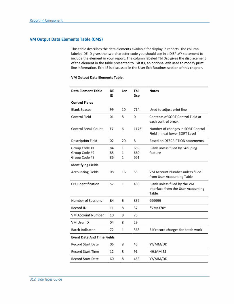
Reporting Component
312 Interfaces Guide
VM Output Data Elements Table (CMS)
This table describes the data elements available for display in reports. The column labeled DE ID gives the two-character code you should use in a DISPLAY statement to include the element in your report. The column labeled Tbl Dsp gives the displacement of the element in the table presented to Exit #3, an optional exit used to modify print line information. Exit #3 is discussed in the User Exit Routines section of this chapter.
VM Output Data Elements Table:
Data Element Table DE ID
Len Tbl Dsp
Notes
Control Fields
Blank Spaces 99 10 714 Used to adjust print line
Control Field 01 8 0 Contents of SORT Control Field at each control break
Control Break Count F7 6 1175 Number of changes in SORT Control Field in next lower SORT Level
Description Field 02 20 8 Based on DESCRIPTION statements
Group Code #1 Group Code #2 Group Code #3
84 85 86
1 1 1
659 660 661
Blank unless filled by Grouping feature
Identifying Fields
Accounting Fields 08 16 55 VM Account Number unless filled from User Accounting Table
CPU Identification 57 1 430 Blank unless filled by the VM Interface from the User Accounting Table
Number of Sessions B4 6 857 999999
Record ID 11 8 37 *VM/370*
VM Account Number 10 8 75
VM User ID 04 8 29
Batch Indicator 72 1 563 B if record charges for batch work
Event Date And Time Fields
Record Start Date 06 8 45 YY/MM/DD
Record Start Time 12 8 91 HH.MM.SS
Record Start Date 60 8 453 YY/MM/DD

Reporting Component
Chapter 8: The VM Interface 313
Data Element Table DE ID
Len Tbl Dsp
Notes
Record Start Time 61 8 461 HH.MM.SS
Record Stop Time 13 8 99
Computer Resource Utilization Fields
Total CPU Time 26 10 182 9999.99999; hours CP Overhead + Virtual CPU
Total CPU Time 66 10 503 HHHH.MM.SS
Total CPU Time 91 8 692 HH.MM.SS; averaged at summary levels
CP Overhead Time C4 10 927 9999.99999; hours
CP Overhead Time C5 10 937 HHHH.MM.SS
CP Overhead Time C6 8 947 HH.MM.SS; averaged at summary levels
Virtual CPU Time C7 10 955 9999.99999; hours
Virtual CPU Time C8 10 965 HHHH.MM.SS
Virtual CPU Time C9 8 975 HH.MM.SS; averaged at summary levels
VS Page Reads 73 10 564
VS Page Writes 74 10 574
Total VS Pages 75 10 584 Page Reads + Page Writes
I/O Device Utilization Fields
Cards Read A6 9 781 99999,999
Cards Punched A5 9 772 99999,999
Lines Printed E5 10 1045 99999,999
Spooled Reader I/O Count
33 10 244
Spooled Printer I/O Count
34 10 254 9999,999
Spooled Punch I/O Count
35 10 264
Tape Connect Time 37 10 284 1 tape for 1 hr = 10,000
Non-tape Dedicated 88 10 664 Hours to 5 decimal places
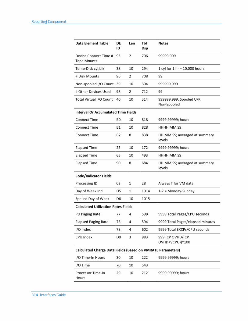
Reporting Component
314 Interfaces Guide
Data Element Table DE ID
Len Tbl Dsp
Notes
Device Connect Time # Tape Mounts
95 2 706 99999,999
Temp-Disk cyl,blk 38 10 294 1 cyl for 1 hr = 10,000 hours
# Disk Mounts 96 2 708 99
Non-spooled I/O Count 39 10 304 999999,999
# Other Devices Used 98 2 712 99
Total Virtual I/O Count 40 10 314 999999,999; Spooled U/R Non-Spooled
Interval Or Accumulated Time Fields
Connect Time B0 10 818 9999.99999; hours
Connect Time B1 10 828 HHHH.MM.SS
Connect Time B2 8 838 HH.MM.SS; averaged at summary levels
Elapsed Time 25 10 172 9999.99999; hours
Elapsed Time 65 10 493 HHHH.MM.SS
Elapsed Time 90 8 684 HH.MM.SS; averaged at summary levels
Code/Indicator Fields
Processing ID 03 1 28 Always T for VM data
Day of Week Ind D5 1 1014 1-7 = Monday-Sunday
Spelled Day of Week D6 10 1015
Calculated Utilization Rates Fields
PU Paging Rate 77 4 598 9999 Total Pages/CPU seconds
Elapsed Paging Rate 76 4 594 9999 Total Pages/elapsed minutes
I/O Index 78 4 602 9999 Total EXCPs/CPU seconds
CPU Index D0 3 983 999 (CP OVHD/(CP OVHD+VCPU))*100
Calculated Charge Data Fields (Based on VMRATE Parameters)
I/O Time-In Hours 30 10 222 9999.99999; hours
I/O Time 70 10 543
Processor Time-In Hours
29 10 212 9999.99999; hours

Reporting Component
Chapter 8: The VM Interface 315
Data Element Table DE ID
Len Tbl Dsp
Notes
Processor Time 69 10 533 HHHH.MM.SS
Adjusted Rate 43 9 340 $9,999.99
Connect Charge B3 11 846
I/O Charge 45 11 360 $999,999.99
Processor Charge 44 11 349
Total Charge 46 13 371 $9999,999.99S
% Total Charge 42 8 332 999.999S
Distributed Charge 47 10 384 $9,999,999
U/R Charge 54 11 403 $999,999.99
Setup Charge 55 10 414 $999,999.99
Credit Amount 79 12 606 $9999,999.99*
Debit Amount 80 12 618 $9999,999.99*
Budget Amount 81 10 630 $9,999,999*
Over/Under Budget 82 13 640
$9999,999.99S*
% Budget Spent 83 6 653
9999.9*
* Based on CREDIT, DEBIT, BUDGET statements
Charging For VM Resources (CMS)
This section applies to you if you elect to produce history records formatted for CMS. If you choose to create records formatted for CA JARS RA for z/VSE, see Charging for VM Resources (VSE) later in this chapter.
The VMRATE statement supplies rates used by CA JARS to calculate dollar charges for use of resources. The rate parameters can be omitted when no data elements involving charges are selected for a given report. The set code on the VMRATE statement, as on all rate and budget control statements, is optional. A blank in position 1 indicates that the statement is used in all reports.

Reporting Component
316 Interfaces Guide
CPU Identification
The CPU Identification code associates each VMRATE statement with the appropriate VM data. When you run the VM Interface translate component, a CPU Identification Code is placed into its output records according to the User Accounting Table you supply. You can also set the CPU ID field with the grouping feature, using GROUP and GROUPC statements. When this product reads those records as input, the CPU Identification on the VMRATE statement must match the corresponding CPU Identification in the records for the rates to be applied.
If your User Accounting Table defined different CPU ID Codes for different classes of users, you will need multiple VMRATE statements to calculate charges for each separate class. If this product reads a record whose CPU ID does not match the CPU ID of any VMRATE statement for a given report, it applies the rates from the first VMRATE statement for the report.
Connect Charge
The Connect Charge is calculated as:
Connect Charge = Connect Time x Connect Time Rate
You supply the Connect Time Rate on a VMPARM statement. It is the dollar amount ($99V99) per hour of connect time. The Connect Time value is in the data, as hours to 5 decimal places.
Processor Charge
This is a charge for CPU time consumed. The basic formula is:
Processor Charge = Processor Time x Basic Processor Rate
Each of these factors (Processor Time and Basic Processor Rate) is explained below.
The first factor, Processor Time, is calculated from CPU times in a record and rates in a VMRATE statement.
Processor Time Algorithm:
Processor Time = Total CPU Time x Total CPU Time Factor
+
Virtual CPU Time x Virtual CPU Time Factor
The two CPU Time factors are percentages (that is, 100 = 100%). A common approach for these factors is to set one to 100 and omit the other (they default to 0). For instance, if you want to charge on Total CPU Time only, set the Total CPU Time Factor to 100 and omit the Virtual CPU Time Factor. To charge entirely on Virtual CPU time, set the Virtual CPU Time Factor to 100 and omit the other factor.
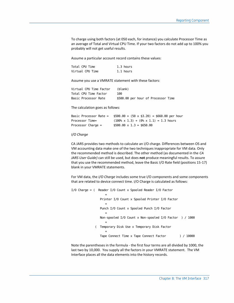
Reporting Component
Chapter 8: The VM Interface 317
To charge using both factors (at 050 each, for instance) you calculate Processor Time as an average of Total and Virtual CPU Time. If your two factors do not add up to 100% you probably will not get useful results.
Assume a particular account record contains these values:
Total CPU Time 1.3 hours
Virtual CPU Time 1.1 hours
Assume you use a VMRATE statement with these factors:
Virtual CPU Time Factor (blank)
Total CPU Time Factor 100
Basic Processor Rate $500.00 per hour of Processor Time
The calculation goes as follows:
Basic Processor Rate = $500.00 + (50 x $3.20) = $660.00 per hour
Processor Time= (100% x 1.3) + (0% x 1.1) = 1.3 hours
Processor Charge = $500.00 x 1.3 = $650.00
I/O Charge
CA JARS provides two methods to calculate an I/O charge. Differences between OS and VM accounting data make one of the two techniques inappropriate for VM data. Only the recommended method is described. The other method (as documented in the CA JARS User Guide) can still be used, but does not produce meaningful results. To assure that you use the recommended method, leave the Basic I/O Rate field (positions 15-17) blank in your VMRATE statements.
For VM data, the I/O Charge includes some true I/O components and some components that are related to device connect time. I/O Charge is calculated as follows:
I/O Charge = ( Reader I/O Count x Spooled Reader I/O Factor
+
Printer I/O Count x Spooled Printer I/O Factor
+
Punch I/O Count x Spooled Punch I/O Factor
+
Non-spooled I/O Count x Non-spooled I/O Factor ) / 1000
+
( Temporary Disk Use x Temporary Disk Factor
+
Tape Connect Time x Tape Connect Factor ) / 10000
Note the parentheses in the formula - the first four terms are all divided by 1000, the last two by 10,000. You supply all the factors in your VMRATE statement. The VM Interface places all the data elements into the history records.

Reporting Component
318 Interfaces Guide
You supply all factors as three digit numbers. The first four factors in the formula, the ones that apply to I/O counts, are interpreted as dollars and cents ($9V99). They are the dollar charge per 1000 I/O of the various types.
The last two factors, the Temporary Disk Factor and the Tape Connect Factor, are interpreted as dollars to one decimal place ($99V9). The Temporary Disk Factor is the rate you want to charge for one cylinder-hour of temporary disk use. The Tape Connect Factor is the rate you want to charge for one hour's use of one tape drive. You must select rates that are even multiples of $0.10 - if you enter a rate of 127 in the VMRATE statement, it is interpreted as $12.70 per hour.
Temporary Disk Use is stored in the record in units of 1 ten-thousandth of a cylinder hour. For example, one cylinder of temporary disk, held for one hour, produces the number 10,000 in the Temporary Disk Use field. Two cylinders held for 3 hours would produce 60,000 for Temporary Disk Use.
Tape Connect Time is stored in the record in units of 1 ten-thousandth of an hour. For example, one tape drive held for one hour produces the number 10,000 in the Tape Connect Time field. Two tape-drives held for three hours each would produce 60,000 for Tape Connect Time.
If temporary disk is allocated on an FBA device, the raw VM account records contain a count of FBA blocks rather than a number of cylinders. The VM Interface converts the FBA block count to an equivalent number of cylinders. It divides the block count by a number that represents the number of blocks in one cylinder. The default value for this number is 1000. You may supply a different number in the FBLK parameter of your VMPARM statement when you run the VM Interface.
Unit Record Charge
The Unit Record Charge gives you an alternate method of charging for unit record use (reader, punch and printer). The numbers found in Reader I/O Count and Punch I/O Count are also available as Cards Read and Cards Punched. The Printer I/O Count figure is also available as Total Lines Printed and Standard Lines Printed.
The Unit Record Rates (Reader Rate and Punch Rate) on the VMRATE statement permit you to charge for the use of unit record devices as follows:
U/R Charge = ( Cards Read x Reader Rate
+
Cards Punched x Punch Rate ) / 1000
To include Lines Printed in the U/R Charge, you must supply a FORMRATE statement. If you include a Line/Card Rate in the FORMRATE statement, the U/R Charge is adjusted to:
U/R Charge = U/R Charge
+
(Lines Printed x Line/Card Rate)/1000

Reporting Component
Chapter 8: The VM Interface 319
Thus all three unit record types may be included in the U/R Charge. Be careful not to bill twice for the same activity. If you supply a Spooled Reader I/O Factor in a VMPARM statement, you include a charge for reader I/O into the total I/O Charge. If you also supply a Reader Rate in the VMPARM statement, you include a charge for the same reader I/O into the total U/R Charge. You should choose one or the other way to bill for each type of unit record activity.
The Tape and Disk Allocation Charge fields permit you to charge for tape mounts and disk mounts.
Setup Charge = # of Tape Mounts x Tape Mount Charge
+
# of Disk Mounts x Disk Mount Charge
Total Charge
The Total Charge is defined as:
Total Charge = Connect Charge
+
Processor Charge
+
I/O Charge
+
U/R Charge
+
Setup Charge
If you supply a Minimum Session Charge on the VMRATE statement, and that charge is greater than the Total Charge computed above, the Minimum Session Charge is used as the Total Charge.
If you are using the Project, Product, or Interval Accounting features of the VM Interface, you should probably not supply a Minimum Session Charge. A session means the period of time covered by one raw type 01 VM account record. If no special data collection features are active, that is the entire user session from LOGON to LOGOFF. If the VM Interface is gathering extra information through project, product or interval accounting, there may be many type 01 records created for a single user in a day's work, some representing only a short time interval. A Minimum Session Charge could severely overcharge a user.

Reporting Component
320 Interfaces Guide
Charging for VM Resources (VSE)
This section applies to you if you elect to produce history records formatted for CA JARS RA for z/VSE. If you choose to create records formatted for CMS, see the section entitled Charging for VM Resources (CMS).
The CPURATE statement supplies rates used by this product to calculate dollar charges for resource usage. The rate parameters may be omitted when no data elements involving charges are selected for a given report. The set code on the CPURATE statement, as on all rate and budget control statements, is optional. A blank in position 1 indicates that the statement is used in all reports.
CPU Identification
The CPU Identification code associates each CPURATE statement with the appropriate VM data. When you run the VM Interface translate component, the VM Interface places a CPU Identification Code into its output records according to the User Accounting Table you supply. When CA JARS reads those records as input, the CPU Identification on the CPURATE statement must match the corresponding CPU Identification in the records for the rates to be applied.
If your User Accounting Table defined different CPU ID Codes for different classes of users, you need multiple CPURATE statements to calculate charges for each separate class. If this product reads a record whose CPU ID does not match the CPU ID of any CPURATE statement for a given report, it applies the rates from the first CPURATE statement for the report.
Processor Charge
This is a charge that combines Total CPU Time and Connect Time. The basic formula is:
Processor Charge = Processor Time x Basic Processor Rate
You supply the Basic Processor Rate in the CPURATE statement. The calculation of Processor Time is explained as follows:
Processor Time is calculated from times in a record and rates in a VMRATE statement.
Processor Time Algorithm (VSE):
Processor Time = ( Total CPU Time x Total CPU Time Factor
+
Connect Time x Connect Time Factor ) /3600

Reporting Component
Chapter 8: The VM Interface 321
The two factors are percentages (that is, 100 = 100%). One possible approach for these factors is to set one to 100 and omit the other (they default to 0). For instance, if you want to charge on Total CPU Time only, set the Total CPU Time Factor to 100 and omit the Connect Time Factor. To charge entirely on Connect time, set the Connect Time Factor to 100 and omit the other factor. If you use both factors (at 050 each, for instance) you calculate Processor Time as an average of Total CPU Time and Connect Time.
Often, people think in terms of two rates, a rate per hour they want to charge for Connect Time, and a rate per hour they want to charge for Total CPU Time. As you can see from the above formula, CA JARS does not calculate its charges in exactly that way. With a little arithmetic, though, you can convert your desired rates into factors that produces the total charge you want.
Suppose you want to charge C dollars per hour for Connect Time, and T dollars per hour for Total CPU Time. T of course is a larger rate than C. The simplest approach is to set:
Basic Processor Rate = T (your rate for Total CPU Time)
Total CPU Time Factor = 100
Connect Time Factor = C/T (rounded to whole percent)
Let us carry through an example. You want to charge:
$300.00 per hour for Total CPU Time
$60.00 per hour for Connect Time
A user has accumulated the following figures:
3600 seconds (1 hour) of Connect Time
900 seconds (15 minutes) of Total CPU Time
The right answer, from the calculation you are used to, is:
Processor Charge = ($60 x 1 hour) + ($300 x .25 hours) = $135.00
Using the formulas suggested, you set:
Basic Processor Rate = $300.00 (same as your desired CPU Time rate)
Total CPU Time Factor = 100
Connect Time Factor = 60/300 = 020% (ratio of your two rates)
CA JARS calculates the Processor Charge as:
Processor Time = ( (100% x 900 sec) + (20% x 3600 sec) ) /3600
= ( 900 sec + 720 sec ) /3600
= 0.45 hours
Processor Charge = $300.00 x 0.45 = $135.00

Reporting Component
322 Interfaces Guide
There could be some loss of precision if the ratio of your two desired rates does not come out evenly to a whole percent. You can improve the precision with one more adjustment. You can divide the Basic Processor Rate by any number you like, without changing the Processor Charge, if you multiply both the Total CPU Time Factor and the Connect Time Factor by that same number.
For instance, in the previous example, dividing the Basic Processor Rate by 5 gives $60.00 per hour. Multiplying both factors by 5 gives 500% and 100% for the Total CPU Time Factor and the Connect Time Factor. The calculation would then be:
Processor Time = ( (500% x 900 sec) + (100% x 3600 sec) ) /3600
= ( 4500 sec + 3600 sec) /3600
= 2.25 hours
Processor Charge = $60.00 x 2.25 = $135.00
If you can find an adjustment factor that makes the ratio of your two rates come out very close to a whole percent, and does not cause much rounding error when you divide it into your Basic Processor Rate, you can make the calculation almost perfectly match the calculation you are used to.
I/O Charge
CA JARS RA for z/VSE provides two methods to calculate an I/O charge. Differences between VSE and VM accounting data make one of the two techniques inappropriate for VM data. Only the recommended method is described. The other method can still be used, but does not produce meaningful results. To assure that you use the recommended method, leave the Basic I/O Rate field (positions 15-17) blank in your CPURATE statements.
For VM data, the I/O Charge includes one true I/O component and two components that are related to device connect time. I/O Charge is calculated as follows:
I/O Charge = ( Non-spooled I/O Count x Non-spooled I/O Factor
+
Temporary Disk Use x Temporary Disk Factor
+
Tape Connect Time x Tape Connect Factor ) / 1000
Note the parentheses in the formula: all three terms are divided by 1000. You supply all the factors in your CPURATE statement. The VM Interface places all the data elements into the history records.
You supply all factors as four digit numbers, interpreted as dollars and cents ($99V99). The Non-spooled I/O Factor is the rate you want to charge per 1000 nonspooled SIOs. The Temporary Disk Factor is the rate you want to charge for one cylinder-hour of temporary disk use. The Tape Connect Factor is the rate you want to charge for one hour's use of one tape drive.

Reporting Component
Chapter 8: The VM Interface 323
Temporary Disk Use is stored in the record in units of one/thousandth of a cylinder hour. For example, one cylinder of temporary disk, held for one hour, produces the number 1,000 in the Temporary Disk Use field. Two cylinders held for three hours would produce 6,000 for Temporary Disk Use.
Tape Connect Time is stored in the record in units of one/thousandth of an hour. For example, one tape drive held for one hour produces the number 1,000 in the Tape Connect Time field. Two tape drives held for three hours each would produce 6,000 for Tape Connect Time.
If temporary disk is allocated on an FBA device, the raw VM account records contain a count of FBA blocks rather than a number of cylinders. The VM Interface converts the FBA block count to an equivalent number of cylinders. It divides the block count by a number that represents the number of blocks in one cylinder. The default value for this number is 1000. You may supply a different number in the FBLK parameter of your VMPARM statement when you run the VM Interface.
Unit Record Charge
The Unit Record Charge gives you the ability to charge for unit record use (reader, punch and printer). The Reader Rate on the CPURATE statement defines the rate you wish to charge per 1000 cards read. The first calculation of U/R Charge is:
U/R Charge = (Cards Read x Reader Rate) / 1000
To include Lines Printed in the U/R Charge, you must supply a FORMRATE statement with a Forms ID of *PR*. If you include a Line/Card Rate in this FORMRATE statement, the U/R Charge is adjusted to:
U/R Charge = U/R Charge
+
(Lines Printed x Line/Card Rate)/1000
To include statements Punched in the U/R Charge, you must supply a FORMRATE statement with a Forms ID of *PU*. If you include a Line/Card Rate in this FORMRATE statement, the U/R Charge is adjusted to:
U/R Charge = U/R Charge
+
(Cards Punched x Line/Card Rate)/1000
By including both *PU* and *PR* FORMRATE statements, you can have both Lines Printed and Cards Punched included in the U/R Charge, along with Cards Read.

Reporting Component
324 Interfaces Guide
The Tape and Disk Allocation Charge fields permit you to charge for tape mounts and disk mounts.
Setup Charge = # of Tape Mounts x Tape Mount Charge
+
# of Disk Mounts x Disk Mount Charge
Total Charge
The Total Charge is defined as:
Total Charge = Processor Charge
+
I/O Charge
+
U/R Charge
+
Setup Charge
Each of the four Charges in the above formula can be adjusted by a percentage from a PRIORITY statement.
If you supply a Minimum Job Charge on the CPURATE statement, and that charge is greater than the Total Charge computed above, the Minimum Job Charge is used as the Total Charge.
If you are using the Project, Product, or Interval Accounting features of the VM Interface, you should probably not supply a Minimum Job Charge. A job means the period of time covered by one raw type 01 VM account record. If no special data collection features are active, that is the entire user session from LOGON to LOGOFF. If the VM Interface is gathering extra information through project, product or interval accounting, there may be many type 01 records created for a single user in a day's work, some representing only a short time interval. A Minimum Job Charge could severely overcharge a user.
If you elect to produce VSE-formatted records from the translation component of the VM Interface, you require a copy of the CA JARS RA for z/VSE product to report on them. There are a two differences in the use of control statements you must take into account.
■ You must use the CPURATE statement instead of the VMRATE statement.
■ The use of the FORMRATE statement is somewhat different. These differences are detailed in the following sections.

Reporting Component
Chapter 8: The VM Interface 325
CPURATE Statement
This statement is input to CA JARS RA for z/VSE, if you choose to use that product as the reporting component for the VM Interface.
To bill for VM data under CA JARS RA for z/VSE, you use the CPURATE statement to define the rate parameters for the billing algorithm. VM data is treated as if it were POWER Data. Therefore, POWER data cannot be processed concurrently with VM data unless the grouping feature is used to select and/or charge CPU ID for at least one type of data.
Position Field Length
Field Name Notes
1 1 Set Code
2-9 8 Statement Type CPURATE
10 1 CPU Identification CPU ID or blank
11-14 4 Basic Processor Rate 9999; dollars per hour
15-17 3 Basic I/O Rate 999; dollars per hour; blanks recommended
18-20 21-23
3 3
Connect Time Factor Total CPU Time Factor
999; percentage must be blank or numeric
27-29 30-32 33-35 36-38 39-41
3 3 3 3 3 3
Spool Reader I/O Factor Spool Printer I/O Factor Spool Punch I/O Factor Tape I/O Factor Disk I/O Factor Other I/O Factor
999; SIO count per second; blanks recommended
42-45 4 Reader Rate 99V99; dollars per 1000 cards
46-49 4 Tape Rate 99V99; dollars per 1000
50-53 4 Temporary-Disk Rate 99V99; dollars per cyl-hour
54-57 4 Non-spooled I/O Rate 99V99; dollars per 1000 I/O
58-61 4 Tape Allocation Charge 99V99; dollars per tape drive
62-65 4 Disk Mount Charge 99V99; dollars per mount
66-69 4 Minimum Session Charge 99V99; dollars
70-80 11 Reserved Not used

Reporting Component
326 Interfaces Guide
FORMRATE Statement
Place *PR* or *PU* in the Forms ID field. The number you enter in the Line/card Rate field is then your charge per 1000 lines sent to a virtual printer (*PR* Forms ID) or per 1000 virtual cards punched (*PU* Forms ID). You may submit two FORMRATE statements to a single run, one to charge for lines printed, the other to charge for cards punched.
Position Field Length
Field Name Notes
1 1 Set Code Optional
2-9 8 Statement Type FORMRATE
10 1 CPU Identification
11 1 Reserved Not used
12-15 4 Forms ID *PR* or *PU*
16-19 4 Setup Charge 99V99; dollars
20-23 4 Line/Card Rate 99V99; dollars per 1000
24-80 57 Reserved Not used
VM Accounting Versus Batch Accounting
The accounting data collected by VM is primarily oriented towards overall system operation. Data is collected for each virtual machine and represents total resource usage by each virtual machine. An individual virtual machine may be an OS machine, a VSE machine, or a CMS machine.
For CMS users, the VM data is the only accounting data. If you want to report on overall system use and performance, it may be appropriate to use the VM accounting data for all virtual machines. For billing purposes, though, you may instead consider using VM accounting data for CMS users, but still use SMF and/or POWER/VS accounting data for users of your guest batch systems.
The VM Interface puts VM data into the same record format used for SMF and POWER/VS data. Whenever possible, comparable data is in the same fields. This makes it easy to mix VM data and batch accounting data in a single report.

User Exit Routines
Chapter 8: The VM Interface 327
Some ideas for designing mixed-data reports:
■ You can reject VM accounting data on the batch machines using the User Accounting Table.
■ With the User Accounting Table, you can insert CPU IDs that differentiate billable and nonbillable usage.
■ The grouping feature can select or reject data to keep only the data appropriate for each report.
User Exit Routines
In order to accommodate installation accounting and reporting requirements not supported by the standard features of the Report Writer, provision is made for user exit routines to augment or modify the actions normally taken. These user exit routines may be written in any language that supports the standard OS/VS program linkage conventions, but COBOL or the Assembler are probably the easiest to use with the least likelihood of problems. The Assembler must be used for input or account exits that intend to insert records. This section describes the parameters passed to exit routines at each of the following four phases in the Report Writer's processing logic:
■ Creation of the working account file (account exit).
■ Processing of the working account file prior to the application of billing algorithms (exit-1 exit).
■ Processing of the working account file after the application of billing algorithms (exit-2 exit).
■ Processing of user-defined reports prior to formatting a report print line (exit-3 exit).
Exit routines must be present on an accessed disk. A routine may be in the form of a TEXT file, a member in a GLOBALed TXTLIB, or a member in a GLOBALed LOADLIB. To use a LOADLIB member, you must also include the LOADLIB in the FILEDEF statement for $SYSLIB. You should modify the CAIJV050 EXEC to include the statement:
FILEDEF $SYSLIB DISK lib-name LOADLIB fm (CONCAT
It is not necessary to link edit an exit routine with the Report Writer. The exit routine should be compiled and linked independently of the Report Writer.
Exit routines are invoked according to standard linkage conventions, as follows:
Register Description
13 Address of a register save area.
14 Return address.
15 Address of the exit routine's entry point.
1 Address of the parameter list.
User Exit Routines
328 Interfaces Guide
Account Exit
The account exit, if activated, passes each account record just as it is about to be written to the account file. This exit may modify, delete, or insert records at this point. Note that extreme care must be exercised if records are being inserted since no further editing or validation operations are performed before the record is written to the account file.
The parameter list contains the following parameters:
Word Description
1 Address of logical record currently being processed (following the Record Description Word (RDW)).
2 Address of a 1-character disposition indicator.
3 Address of a 1-character insertion indicator.
Each Account Record is made available to the user exit routine.
A value of EBCDIC blank (hex '40') in the disposition indicator on entry to the account exit indicates that a record is available to be processed. If the exit needs to modify or extract information from the record, it can do so at this time.
If the modifications include a change to the record length, the exit must move the record to its own work area, make the required modifications to the record in the work area, then store the address of the modified record back into the first word of the parameter list before returning control to the Report Writer.
If the exit needs to delete the record from further processing, it must set the disposition indicator to any nonblank value before returning control to the Report Writer. In order to insert records into the input stream, the exit must set the insertion indicator to any nonblank value, and store the address of the record to be inserted in the first word of the parameter list before returning control to the Report Writer. The record to be inserted must be preceded by a valid Record Descriptor Word (RDW) that contains the length of the record (including the four bytes for the RDW), but the address stored into the first word of the parameter list must point to the beginning of the record after the RDW.
When the user exit is next invoked, after the inserted record has been processed, it again receives a pointer to the original record, which it can now choose to process, or delete, or it can continue inserting records of its own.
High values (hex 'FF') in the disposition indicator on entry to the account exit indicates that end-of-file has been reached. No record is available for processing at this point, nor can any additional records be inserted. The account exit should take this opportunity to prepare totals, generate user-formatted reports, close its files, etc.

User Exit Routines
Chapter 8: The VM Interface 329
Exit #1
This exit provides you with control immediately following the grouping feature logic and prior to the application of the accounting algorithm for each accounting record being processed. This lets you to test or apply a unique algorithm to any record reaching this phase of processing.
Historical data is passed to the user exit routine prior to all old account records.
The parameter list for this exit is as follows:
Word Description
1 Address of Set Code for report currently being generated
2 Address of accounting record currently being processed
3 Address of RATE statement information table
4 Address of PRIORITY statement information table
5 Address of working storage area
6 Address of disposition indicator to be set by user
7 Address of VMRATE statement information table
8 Address of FORMRATE statement information table.
9 Address of RJERATE statement information table.
All these tables are described on the following pages. For VM data, the RATE, PRIORITY, and RJERATE statement information tables contain binary zeros, since these three statement types are not used under CMS.
The RATE statement information table consists of a variable number of entries, with the last valid entry being followed by an entry containing low-values (x'00'). Each entry is basically in the same format as the RATE statement as shown on the following page.
RATE Statement:
Field Name Field Length Displacement
CPU Identification 1 0
Basic Processor Rate 4 1
Basic I/O Rate 3 5
Core Factor 4 8
Elapsed Time Factor 3 12

User Exit Routines
330 Interfaces Guide
Field Name Field Length Displacement
Total CPU Time Factor 3 15
SRB CPU Time Factor 3 18
TCB CPU Time Factor 3 21
Reader I/O Factor 3 24
Printer I/O Factor 3 27
Punch I/O Factor 3 30
Tape I/O Factor 3 33
Disk I/O Factor 3 36
Other I/O Factor 3 39
Reader Rate 3 42
Printer Rate* 3 45
Special Print Rate* 3 48
Punch Rate* 3 51
Tape Allocation Charge 3 54
Disk Allocation Charge 3 57
Minimum Job Charge 4 60
Maximum Step Rate 4 64
Step Time Criteria 2 68
Core Indicator 1 70
* Not used for OS jobs (FORMRATE used instead)
The VMRATE statement information table consists of a variable number of entries with the last entry being followed by an entry containing low-values (x'00'). Each entry is basically in the same format as the VMRATE statement as follows. All data is in EBCDIC format.
VMRATE Statement:
Field Name Field Length Displacement
CPU Identification 1 0
Basic Processor Rate 4 1
Basic I/O Rate 3 5
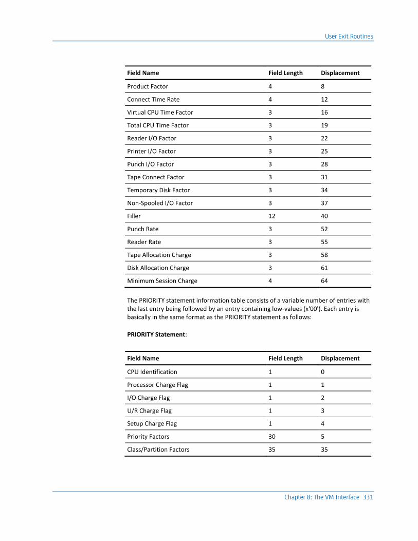
User Exit Routines
Chapter 8: The VM Interface 331
Field Name Field Length Displacement
Product Factor 4 8
Connect Time Rate 4 12
Virtual CPU Time Factor 3 16
Total CPU Time Factor 3 19
Reader I/O Factor 3 22
Printer I/O Factor 3 25
Punch I/O Factor 3 28
Tape Connect Factor 3 31
Temporary Disk Factor 3 34
Non-Spooled I/O Factor 3 37
Filler 12 40
Punch Rate 3 52
Reader Rate 3 55
Tape Allocation Charge 3 58
Disk Allocation Charge 3 61
Minimum Session Charge 4 64
The PRIORITY statement information table consists of a variable number of entries with the last entry being followed by an entry containing low-values (x'00'). Each entry is basically in the same format as the PRIORITY statement as follows:
PRIORITY Statement:
Field Name Field Length Displacement
CPU Identification 1 0
Processor Charge Flag 1 1
I/O Charge Flag 1 2
U/R Charge Flag 1 3
Setup Charge Flag 1 4
Priority Factors 30 5
Class/Partition Factors 35 35
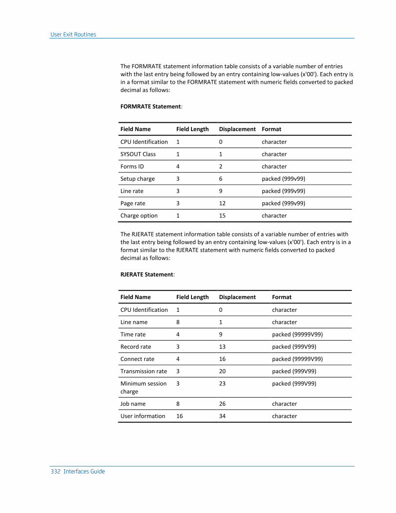
User Exit Routines
332 Interfaces Guide
The FORMRATE statement information table consists of a variable number of entries with the last entry being followed by an entry containing low-values (x'00'). Each entry is in a format similar to the FORMRATE statement with numeric fields converted to packed decimal as follows:
FORMRATE Statement:
Field Name Field Length Displacement Format
CPU Identification 1 0 character
SYSOUT Class 1 1 character
Forms ID 4 2 character
Setup charge 3 6 packed (999v99)
Line rate 3 9 packed (999v99)
Page rate 3 12 packed (999v99)
Charge option 1 15 character
The RJERATE statement information table consists of a variable number of entries with the last entry being followed by an entry containing low-values (x'00'). Each entry is in a format similar to the RJERATE statement with numeric fields converted to packed decimal as follows:
RJERATE Statement:
Field Name Field Length Displacement Format
CPU Identification 1 0 character
Line name 8 1 character
Time rate 4 9 packed (99999V99)
Record rate 3 13 packed (999V99)
Connect rate 4 16 packed (99999V99)
Transmission rate 3 20 packed (999V99)
Minimum session charge
3 23 packed (999V99)
Job name 8 26 character
User information 16 34 character
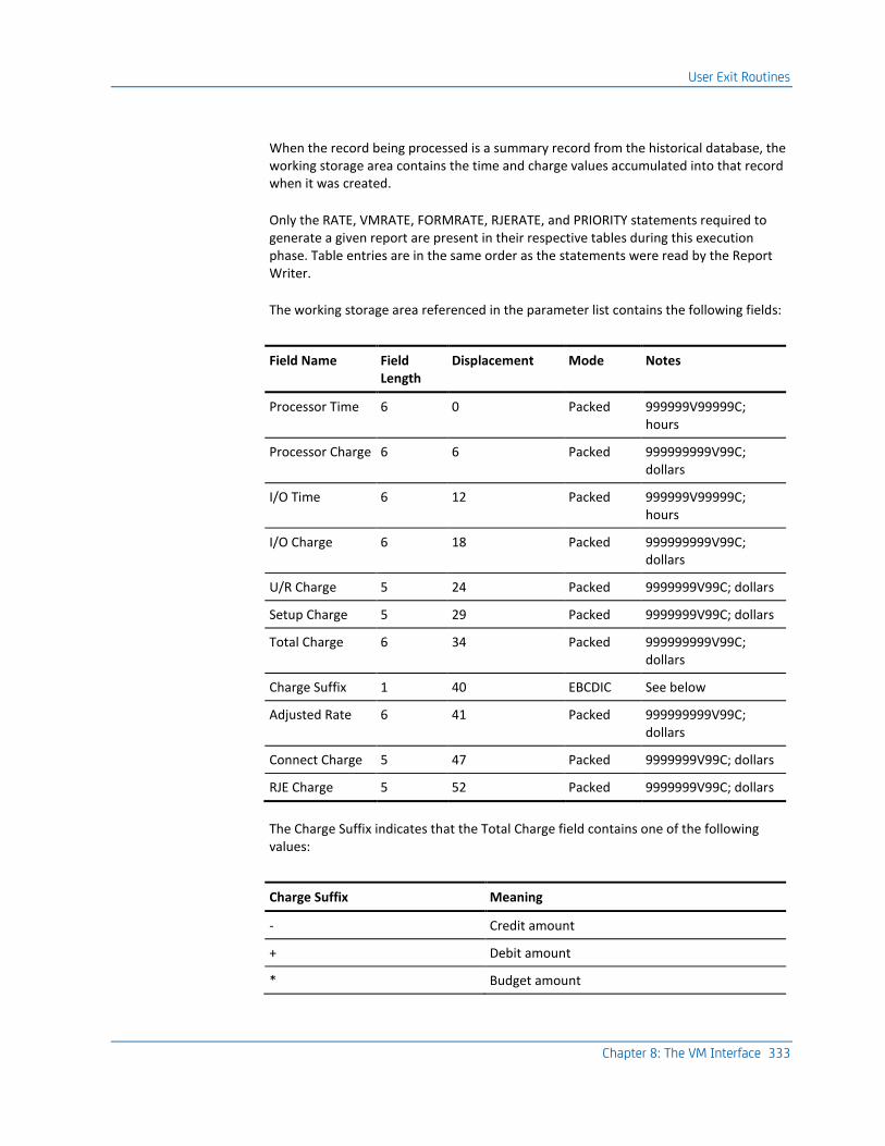
User Exit Routines
Chapter 8: The VM Interface 333
When the record being processed is a summary record from the historical database, the working storage area contains the time and charge values accumulated into that record when it was created.
Only the RATE, VMRATE, FORMRATE, RJERATE, and PRIORITY statements required to generate a given report are present in their respective tables during this execution phase. Table entries are in the same order as the statements were read by the Report Writer.
The working storage area referenced in the parameter list contains the following fields:
Field Name Field Length
Displacement Mode Notes
Processor Time 6 0 Packed 999999V99999C; hours
Processor Charge 6 6 Packed 999999999V99C; dollars
I/O Time 6 12 Packed 999999V99999C; hours
I/O Charge 6 18 Packed 999999999V99C; dollars
U/R Charge 5 24 Packed 9999999V99C; dollars
Setup Charge 5 29 Packed 9999999V99C; dollars
Total Charge 6 34 Packed 999999999V99C; dollars
Charge Suffix 1 40 EBCDIC See below
Adjusted Rate 6 41 Packed 999999999V99C; dollars
Connect Charge 5 47 Packed 9999999V99C; dollars
RJE Charge 5 52 Packed 9999999V99C; dollars
The Charge Suffix indicates that the Total Charge field contains one of the following values:
Charge Suffix Meaning
- Credit amount
+ Debit amount
* Budget amount

User Exit Routines
334 Interfaces Guide
Charge Suffix Meaning
M Minimum job charge
B Block time charge
blank Normal job charge
Each accounting record and all pertinent billing parameters are made available through the parameter list. You can modify information in the accounting record and calculate the various time and charge fields related to the record.
Upon entry to the user exit routine, the time and charge fields in working storage are initialized and available for calculations. When the record being processed is a summary record from the historical database, the working storage area contains the time and charge values accumulated into that record when it was created.
The one-byte EBCDIC disposition indicator, as referenced through the parameter list, is blank upon entry to the user exit routine. A hex 'FF' (high values) upon entry indicates that an end-of-file condition has occurred and no further record processing is to be performed.
You should take this opportunity to prepare totals, generate user-formatted reports, close any files you opened, etc. You can optionally set the one-byte EBCDIC disposition indicator to specify the following action to be taken upon each return to the Report Writer:
Disposition Indicator
Meaning
blank Default - normal processing continues with calculating values in working storage area using standard accounting algorithm.
1 Skip standard accounting algorithm calculations - use values in working storage area as placed there by user exit routine.
2 Reject record from further processing - read next input accounting record.
Exit #2
This exit gives you control immediately following the completion of the standard accounting algorithm calculations and prior to the construction of user sort control fields, as specified by the SORT statement, for each accounting record being processed. This lets you perform tests to verify the time and charge calculations or make unique billing adjustments to any record reaching this phase of processing. The parameter list and record processing sequence for this exit is identical to that of Exit #1.

User Exit Routines
Chapter 8: The VM Interface 335
Each accounting record and all pertinent billing parameters are made available through the parameter list. You can modify information in the accounting record or any field in the working storage area made available through the parameter list. Upon entry to the user exit routine, the time and charge fields in working storage contain the results of the standard accounting algorithm calculations based on the appropriate RATE, TSORATE, FORMRATE, RJERATE, and PRIORITY statements.
The one-byte EBCDIC disposition indicator, as referenced through the parameter list, is blank upon entry to the user exit routine. A hex 'FF' (high values) upon entry indicates that an end-of-file condition has occurred and no further record processing is to be performed. You should take this opportunity to prepare totals, generate user-formatted reports, close any files you have opened, etc.
You can optionally set the one-byte disposition indicator to specify the necessary action to be taken upon return to the Report Writer. If you have set the disposition indicator to any nonblank character, then the record is automatically rejected from further processing.
Exit #3
This exit provides you with control during the output phase while generating the user-defined reports. This gives you the capability of modifying print line information or using summarized data for reporting purposes unique to their installation. The parameter list for this exit is as follows:
Word Description
1 Address of Set Code for report currently being generated
2 Address of print line identification code
3 Address of record type indicators
4 Address of Output Data Elements Table
The print line identification code referenced in the parameter list defines the type of print line currently being developed by the Report Writer. This code is a one-byte binary number defining the type of information currently stored in the Output Data Elements Table:
Print Line ID Meaning
X'01' Top line of output data element titles available for display.
X'02' Bottom line of output data element titles available for display.
X'03' Output data elements available for display at detail level (that is, job and job step records).

User Exit Routines
336 Interfaces Guide
Print Line ID Meaning
X'04' Output data elements available for display at final summarization level.
X'05' Output data elements available for display at summarization level 1.
X'06' Output data elements available for display at summarization level 2.
X'07' Output data elements available for display at summarization level 3.
X'08' Output data elements available for display at summarization level 4.
X'09' Output data elements available for display at summarization level 5.
X'50' Output data elements available for display as level 1 header information.
X'60' Output data elements available for display as level 2 header information.
X'70' Output data elements available for display as level 3 header information.
X'80' Output data elements available for display as level 4 header information.
X'90' Output data elements available for display as level 5 header information.
X'FF' End-of-file condition has occurred and no further record processing is to be performed. Previous entry should have been with identification code X'04' for final totals.
If the print line identification code is equal to X'03', then the record type indicator defines which type of record is currently being processed to develop the detail print line. The record type indicator has no meaning when the print line identification code is a value other than X'03'. This indicator is a two-byte EBCDIC field containing one of the following values:
Record Type Indicator
Meaning
1 Output Data Elements Table contains job step level information.
1 Output Data Elements Table contains job level information.
11 Output Data Elements Table contains information for a one-step job. Data created by the VM Interface is always treated as a one-step job.
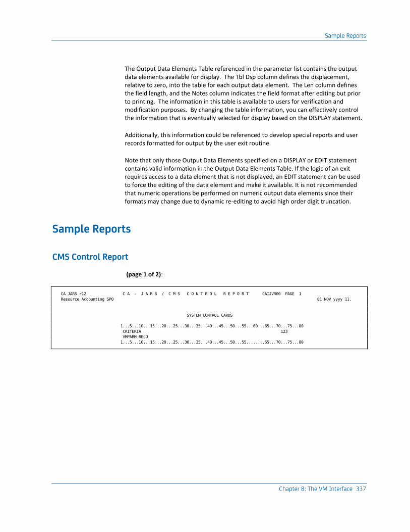
Sample Reports
Chapter 8: The VM Interface 337
The Output Data Elements Table referenced in the parameter list contains the output data elements available for display. The Tbl Dsp column defines the displacement, relative to zero, into the table for each output data element. The Len column defines the field length, and the Notes column indicates the field format after editing but prior to printing. The information in this table is available to users for verification and modification purposes. By changing the table information, you can effectively control the information that is eventually selected for display based on the DISPLAY statement.
Additionally, this information could be referenced to develop special reports and user records formatted for output by the user exit routine.
Note that only those Output Data Elements specified on a DISPLAY or EDIT statement contains valid information in the Output Data Elements Table. If the logic of an exit requires access to a data element that is not displayed, an EDIT statement can be used to force the editing of the data element and make it available. It is not recommended that numeric operations be performed on numeric output data elements since their formats may change due to dynamic re-editing to avoid high order digit truncation.
Sample Reports
CMS Control Report
(page 1 of 2):
CA JARS r12 C A - J A R S / C M S C O N T R O L R E P O R T CAIJVR00 PAGE 1
Resource Accounting SP0 01 NOV yyyy 11.
SYSTEM CONTROL CARDS
1...5...10...15...20...25...30...35...40...45...50...55...60...65...70...75...80
CRITERIA 123
VMPARM RECO
1...5...10...15...20...25...30...35...40...45...50...55........65...70...75...80

Sample Reports
338 Interfaces Guide
(page 2 of 2):
CA JARS r12 C A - J A R S / C M S C O N T R O L R E P O R T CAIJVR00 PAGE 2
Resource Accounting SP0 01 NOV yyyy 11.
CAJV516I 32 VM TYPE 01 RECORDS READ.
CAJV516I 31 VM TYPE 03 RECORDS READ.
CAJV516I 1 VM TYPE 05 RECORDS READ.
CAJV516I 4 USER TYPE C0 RECORDS READ.
CAJV516I 31 CAI TYPE C0 RECORDS READ.
CAJV520I 99 TOTAL RECORDS READ, 94 TOTAL RECORDS USED.
CAJV522I 2 CONTROL CARD(S) READ.
CAJV524I 32 CA JARS HISTORY RECORD(S) WRITTEN.
CAJV504I PROCESSING COMPLETE, RETURN CODE = 0.

Sample Reports
Chapter 8: The VM Interface 339
Termination Report
CA JARS r12 T E R M I N A T I O N R E P O R T CAIJFR99 PAGE 1
Resource Accounting SP0 01 NOV yyyy 11.
** PRODUCT RETURN CODE -- 0000
** MESSAGES -- ** NO MESSAGES PRODUCED **
** FILE USAGE --
NAME- CAIJFPR RECORD COUNTS-
ACCESS - SAM 0 -INPUT
BLKSIZE- 00130 33 -OUTPUT
LRECL - 00130 0 -UPDATED
CISIZE - 00000
RECFORM- FIXED ANS-PR-CTL
USAGE - OUTPUT MOVE
SYS - LST
TAP.OPT- NONE
NAME- CAIJFIN RECORD COUNTS-
ACCESS - SAM 2 -INPUT
BLKSIZE- 00080 0 -OUTPUT
LRECL - 00080 0 -UPDATED
CISIZE - 00000
RECFORM- UNDEFINED
USAGE - INPUT MOVE
SYS - 000
TAP.OPT- NONE
NAME- CAIJVS5 RECORD COUNTS-
ACCESS - SAM 99 -INPUT
BLKSIZE- 00080 0 -OUTPUT
LRECL - 00080 0 -UPDATED
CISIZE - 00000
RECFORM- FIXED
USAGE - INPUT MOVE
SYS - 005
TAP.OPT- STANDARD-LABEL REW-UNLOAD
NAME- CAIJVS6 RECORD COUNTS-
ACCESS - SAM 0 -INPUT
BLKSIZE- 04096 32 -OUTPUT
LRECL - 04092 0 -UPDATED
CISIZE - 00000
RECFORM- VARIABLE BLOCKED
USAGE - OUTPUT MOVE
SYS - 006
TAP.OPT- STANDARD-LABEL REW-UNLOAD
** START TIME -- 11.41.56 END TIME -- 11.42.13 DURATION -- 00.00.17
** END OF JOB --
HIGHEST RETURN CODE -- 0

Sample Reports
340 Interfaces Guide
Daily I/O Activity by User
D A I L Y I / O A C T I V I T Y B Y U S E R
0BEGIN DATE - 01/14/yy RUN DATE - 02/01/yy
END DATE - 01/22/yy PAGE 1
CONNECT READER PRINTER PUNCH NON-SPOOL TOTAL VIRT
CONTROL TIME I/O COUNT I/O COUNT I/O COUNT I/O COUNT I/O COUNT
CMSACT 00.00.29 0 0 0 36 36
CMSBTCH2 00.03.10 66 717 446 1,391 2,620
CMSVTM 00.00.27 0 0 0 52 52
CMS3278 00.00.27 0 0 0 92 92
ISPVM 00.48.25 0 0 0 116 116
MONITOR 01.31.08 1,262 0 1,262 282 2,806
MVSSP 09.32.14 116 5,549 0 27,652 33,317
NOSTROMO 08.04.04 0 0 0 3,212 3,212
OPERATOR 01.31.53 264 0 116 535 915
RSCS 00.00.26 0 0 0 78 78
VMPASS 08.52.54 0 0 0 709 709
850114 30.25.37 1,708 6,266 1,824 34,155 43,953
.
.
.
850115 12.26.23 29,781 372 0 45,208 75,361
.
.
.
850122 18.53.53 11,836 2,568 6,200 95,254 115,858
90.06.53 51,306 78,281 12,424 477,560 619,571
Daily I/O Activity by User Control Statements
0....+....1....+....2....+....3....+....4....+....5....+....6....+....7....+.
| PARMS . . . . . . . . . . . 128 . .
| SELECT . 1 . . . . . . .A . . . . .
| CONFIG READ00C . . . . . . . . . . . .
| VMRATE .0100. 10000500 100 100 .100100100. . . 500500500500 .
|AHEADER . D A I L.Y I / O. A C T I.V I T Y .B Y . U S.E R . . .
|ASORT 00406AE 01608A1. . . . . . . . . . .
|ADISPLAY VO0011B1133134135139140 . . . . . . . . .
|AGROUP 0998 S2554X 2593P 2972 R . . . . . . . . .
|AGROUPC 1*VM/370* . . . . . . . . . . . .
|AGROUPC 200000000 . . X . . . . . . . . . .
|AGROUPC 300000 . . X . . . . . . . . . .
|AGROUPC 4XX . . . . . . . . . . . . .
0....+....1....+....2....+....3....+....4....+....5....+....6....+....7....+.

Sample Reports
Chapter 8: The VM Interface 341
I/O Charge Detail by User
I / O C H A R G E D E T A I L B Y U S E R
BEGIN DATE - 01/14/yy RUN DATE - 02/01/yy
END DATE - 01/22/yy PAGE 2
READER PRINTER PUNCH NON-SPOOL TOTAL VIRT TAPE CONCT TDISK CYL I/O
CONTROL I/O COUNT I/O COUNT I/O COUNT I/O COUNT I/O COUNT HR X 10000 HR X 10000 CHARGE
850115 29,781 372 0 33,039 63,192 8,371 48,680 $90.47
850121 0 21,680 0 28,436 50,116 20,647 443,828 $514.60
A42MAINT 29,781 22,052 0 61,475 113,308 29,018 492,508 $605.07
.
.
.
.
850121 1,052 284 1,451 2,430 5,217 0 204,064 $206.79
850122 0 0 0 0 0 0 117,418 $117.45
CMSGXB 1,052 284 1,451 2,430 5,217 0 321,482 $324.24
.
.
.
850121 0 0 0 9,266 9,266 0 429,552 $438.82
850122 0 0 0 791 791 0 236,477 $237.27
V22MAINT 0 0 0 10,057 10,057 0 666,029 $676.09
.
.
.
51,306 78,281 12,424 477,560 619,571 126,978 3,840,852 $4,523.90
I/O Charge Detail by User Control Statements
0....+....1....+....2....+....3....+....4....+....5....+....6....+....7....+.
| PARMS . . . . . . . . . . . 128 . .
| SELECT . 1 . . . . . . .B . . . . .
| CONFIG READ00C . . . . . . . . . . . .
| VMRATE .0100. 10000500 100 100 .100100100. . . 500500500500 .
|BHEADER . I / O .C H A R G.E D E T.A I L B.Y U S E.R . . .
|BSORT 01608AE 00406A1. . . . . . . . . . .
|BDISPLAY VO001133134135139140137138145 . . . . . . . .
|BGROUP 0998 S . . . . . . . . . . . .
|BGROUPC 1*VM/370* . . . . . . . . . . . .
0....+....1....+....2....+....3....+....4....+....5....+....6....+....7....+.

Sample Reports
342 Interfaces Guide
U/R And Setup Charges by User Report
U / R + S E T U P C H A R G E S B Y U S E R
0BEGIN DATE - 01/14/yy RUN DATE - 02/01/yy
END DATE - 01/22/yy PAGE 2
CARDS CARDS STD LINES U/R TAPE DISK SETUP
CONTROL READ PUNCHED PRINTED CHARGE MOUNTS MOUNTS CHARGE
.
.
.
850115 29,781 0 372 $152.63 1 0 $5.00
850121 0 0 21,680 $216.80 1 0 $5.00
A42MAINT 29,781 0 22,052 $369.43 2 0 $10.00
850121 316 33 0 $1.75 0 0 $.00
850122 2,293 165 1,615 $28.46 0 0 $.00
CMSARS 2,609 198 1,615 $30.21 0 0 $.00
850118 0 0 0 $.00 0 0 $.00
850121 1,052 1,451 284 $15.37 0 0 $.00
850122 0 0 0 $.00 0 0 $.00
CMSGXB 1,052 1,451 284 $15.37 0 0 $.00
U/R and Setup Charges by User Control Statements
0....+....1....+....2....+....3....+....4....+....5....+....6....+....7....+.
| PARMS . . . . . . . . . . . 128 . .
| SELECT . 1 . . . . . . .C . . . . .
| CONFIG READ00C . . . . . . . . . . . .
| VMRATE .0100. 10000500 100 100 .100100100. . . 500500500500 .
| FORMRATE. . 1000 . . . . . . . . . . .
|CHEADER . U / R .+ S E T U P . C H.A R G E S. B Y U.S E R . .
|CSORT 01608AE 00406A1. . . . . . . . . . .
|CDISPLAY VO0011A61A51E51545F01F1155 . . . . . . . .
|CEDIT F0 TF1 T . . . . . . . . . . . .
|CGROUP 0998 S . . . . . . . . . . . .
|CGROUPC 1*VM/370* . . . . . . . . . . . .
0....+....1....+....2....+....3....+....4....+....5....+....6....+....7....+.

Sample Reports
Chapter 8: The VM Interface 343
Processor and Connect Charge Breakdown by User and Date
P R O C E S S O R A N D C O N N E C T C H A R G E
B R E A K D O W N B Y U S E R A N D D A T E
BEGIN DATE - 01/14/yy RUN DATE - 02/01/yy
END DATE - 01/22/yy PAGE 9
PROCESS PROCESS CONNECT CONNECT FIRST PROD ADJUSTED TOTAL PERCENT
TIME CHARGE TIME CHARGE PRODUCT VAL RATE CHARGE TOTAL
.
.
.
.00010 $.05 .01916 $.19 0 $500.00 $.24 .007
.00059 $.30 .08888 $.89 0 $500.00 $1.19 .033
.00131 $.66 .10111 $1.01 0 $500.00 $1.67 .047
.00087 $1.04 .00888 $.09 JSSCJSI 70 $1,200.00 $1.13 .032
.00002 $.01 .00000 $.00 0 $500.00 $.01 .000
.00027 $.30 .00083 $.01 LOADLIB 60 $1,100.00 $.31 .009
.00207 $2.48 .00611 $.06 JSSCJSI 70 $1,200.00 $2.54 .071
.00172 $.86 .13055 $1.31 0 $500.00 $2.17 .061
.00122 $.61 .01916 $.19 0 $500.00 $.80 .022
.00028 $.31 .00083 $.01 LOADLIB 60 $1,100.00 $.32 .009
.00007 $.04 .00166 $.02 0 $500.00 $.06 .002
.00207 $2.48 .00555 $.06 JSSCJSI 70 $1,200.00 $2.54 .071
.00250 $1.25 .30527 $3.05 0 $500.00 $4.30 .121
.00188 $.94 .07833 $.78 0 $500.00 $1.72 .048
.00029 $.32 .00083 $.01 LOADLIB 60 $1,100.00 $.33 .009
.00271 $1.36 .09750 $.98 0 $500.00 $2.34 .066
.00028 $.31 .00083 $.01 LOADLIB 60 $1,100.00 $.32 .009
.00205 $2.46 .00611 $.06 JSSCJSI 70 $1,200.00 $2.52 .071
.00039 $.20 .14777 $1.48 0 $500.00 $1.68 .047
DATE 850122 .04520 $33.67 4.04672 $40.46 70 $74.13 2.080
USERID CMSARS .07561 $48.89 6.93529 $69.33 70 $118.22 3.320
.
.
.
1.65526 $880.22 268.07097 $2,680.06 70 $3,560.28 100.096
Processor and Connect Charge Breakdown by User and Date Control Statements
0....+....1....+....2....+....3....+....4....+....5....+....6....+....7....+.
| PARMS . . . . . . . . . . . 128 . .
| CONFIG READ00C . . . . . . . . . . . .
| VMRATE .0500. 10001000 100 . . . . . . . . .
|DSELECT . 1 . . . . . . .D . . . . .
|DHEADER . P R O C.E S S O R. A N D .C O N N E.C T . C H.A R G E . .
|DHEADER . B R E A.K D O W N. B Y U.S E R A.N D . D A.T E . . .
|DSORT 01608AE 00406A1. . . . . 1 . . . . .
|DDISPLAY VO0020292442B02B32E4221243346342 . . . . . . .
|DTITLE 02 . . . . . . . . . . . . .
|DDESCRIPT2****0961 . DATE . . . . . . . . . .
|DDESCRIPT1****0881USERID. . . . . . . . . . .
0....+....1....+....2....+....3....+....4....+....5....+....6....+....7....+.

Sample Reports
344 Interfaces Guide
VM Total Charge Summary by User and Date
V M T O T A L C H A R G E S U M M A R Y
B Y U S E R AND D A T E
BEGIN DATE - 01/14/yy RUN DATE - 02/01/yy
END DATE - 01/22/yy PAGE 2
VM CONNECT PROCESS I/O U/R SETUP TOTAL PERCENT
USERID CHARGE CHARGE CHARGE CHARGE CHARGE CHARGE TOTAL
DATE 850115 $10.54 $31.29 $90.47 $148.91 $5.00 $286.21 3.380
DATE 850121 $26.18 $12.72 $514.60 $.00 $5.00 $558.50 6.595
USERID A42MAINT $36.72 $44.01 $605.07 $148.91 $10.00 $844.71 9.975
DATE 850118 $3.33 $.77 $.00 $.00 $.00 $4.10 .048
DATE 850121 $110.51 $6.31 $206.79 $12.53 $.00 $336.14 3.969
DATE 850122 $58.70 $.02 $117.45 $.00 $.00 $176.17 2.080
USERID CMSGXB $172.54 $7.10 $324.24 $12.53 $.00 $516.41 6.097
DATE 850118 $3.33 $.00 $.00 $.00 $.00 $3.33 .039
DATE 850121 $50.76 $44.78 $119.32 $4.86 $.00 $219.72 2.595
DATE 850122 $41.92 $27.64 $131.89 $26.14 $.00 $227.59 2.686
USERID CMSPLM $96.01 $72.42 $251.21 $31.00 $.00 $450.64 5.320
$2,680.06 $880.22 $4,523.90 $318.82 $65.00 $8,468.00 99.958
VM Total Charge Summary by User and Date Control Statements
0....+....1....+....2....+....3....+....4....+....5....+....6....+....7....+.
| PARMS . . . . . . . . . . . 128 . .
| SELECT . 1 . . . . . . .E . . . . .
| CONFIG READ00C . . . . . . . . . . . .
| VMRATE .0500. 10001000 100 100 .100100100. . . 500500500500 .
|EHEADER . V M T.O T A L .C H A R G.E S U M.M A R Y . . . .
|EHEADER . B Y U.S E R AND D A T.E . . . . . . .
|ESORT 01608AE 00406A1. . . . . . . . . . .
|EDISPLAY VO0020B3244245254255246242 . . . . . . . .
|EGROUP 0998 S . . . . . . . . . . . .
|EGROUPC 1*VM/370* . . . . . . . . . . . .
|EDESCRIPT2****1061 . DATE . . . . . . . . . .
|EDESCRIPT1****0881USERID. . . . . . . . . . .
|ETITLE 02 . . VM . . . . USERID . . . . . .
0....+....1....+....2....+....3....+....4....+....5....+....6....+....7....+.

Sample Reports
Chapter 8: The VM Interface 345
Tape and Disk Activity Report
T A P E AND D I S K
A C T I V I T Y R E P O R T
BEGIN DATE - 01/15/yy RUN DATE - 02/01/yy
END DATE - 01/22/yy PAGE 1
VM USER / TAPE CONCT TAPE TDISK CYL CONNECT
REC DATE HR X 10000 MOUNTS HR X 10000 TIME
.
.
.
USERID A42MAINT 20,647 1 443,828 2.61830
USERID BACKUP1A 2,094 1 0 .24111
USERID BACKUP1B 3,330 1 0 .33305
USERID CMSARS 0 0 57,708 2.88857
USERID CMSBEC 0 0 79,952 3.99772
USERID CMSCED 2,705 1 48,666 .99971
USERID CMSGXB 0 0 204,064 10.38663
USERID CMSPLM 0 0 86,692 4.38784
USERID CMSRMG 0 0 3,666 .04250
USERID CMSROA 0 0 796,173 11.19967
USERID JARMAINT 2,647 1 0 .33305
USERID V22MAINT 0 0 429,552 11.05301
DATE 850121 31,423 5 2,150,301 48.48116
.
.
.
DATE 850122 19,989 6 1,631,317 25.65424
63,116 13 3,840,852 76.58063
Tape and Disk Activity Report Control Statements
0....+....1....+....2....+....3....+....4....+....5....+....6....+....7....+.
| PARMS . . . . . . . . . . . 128 . .
| SELECT . 1 . . . . . . .O . . . . .
| CONFIG READ00C . . . . . . . . . . . .
| VMRATE . . . 0500 . 999999999100100999. . . . 500 .
|OHEADER . T A P E. AND D.I S K . . . . . . . .
|OHEADER . A C T I.V I T Y .R E P O R.T . . . . . . .
|OSORT 00406A2 01608A2. . . . . . . . . . .
|ODISPLAY VO0023373F03383B0 . . . . . . . . . .
|ODESCRIPT2****0881USERID. . . . . . . . . . .
|ODESCRIPT1****0881 .DATE. . . . . . . . . . .
|OGROUP 2414X.2453P 4754P 2963 R . . . . . . . . .
|OGROUPC 100000000 . . X . . . . . . . . . .
|OGROUPC 200000 . . X . . . . . . . . . .
|OGROUPC 30000000 . . X . . . . . . . . . .
|OGROUPC 4XXX . . . . . . . . . . . . .
|OTITLE 02VM .USER./ . . REC DATE . . . . . . .
|OEDIT F0 T . . . . . . . . . . . . .
0....+....1....+....2....+....3....+....4....+....5....+....6....+....7....+.
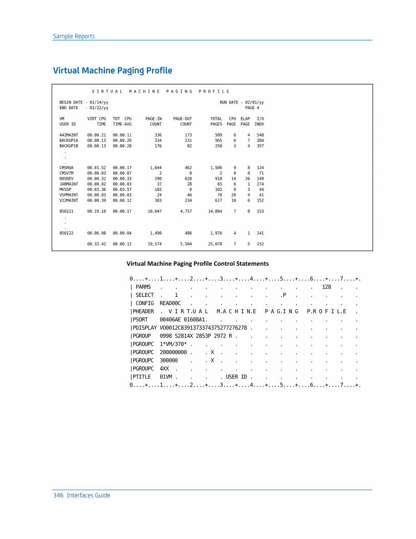
Sample Reports
346 Interfaces Guide
Virtual Machine Paging Profile
V I R T U A L M A C H I N E P A G I N G P R O F I L E
BEGIN DATE - 01/14/yy RUN DATE - 02/01/yy
END DATE - 01/22/yy PAGE 4
VM VIRT CPU TOT CPU PAGE-IN PAGE-OUT TOTAL CPU ELAP I/O
USER ID TIME TIME-AVG COUNT COUNT PAGES PAGE PAGE INDX
A42MAINT 00.00.21 00.00.11 336 173 509 6 4 548
BACKUP1A 00.00.13 00.00.20 334 231 565 6 7 384
BACKUP1B 00.00.13 00.00.28 176 82 258 3 4 357
.
.
.
CMSROA 00.01.52 00.00.17 1,044 462 1,506 9 8 124
CMSVTM 00.00.03 00.00.07 2 0 2 0 0 71
DOSDEV 00.00.32 00.00.33 290 628 918 14 26 149
JARMAINT 00.00.02 00.00.03 37 28 65 6 1 274
MVSSP 00.03.36 00.03.57 102 0 102 0 3 44
VSPMAINT 00.00.03 00.00.03 24 46 70 20 4 41
V22MAINT 00.00.39 00.00.12 383 234 617 10 6 152
850121 00.19.10 00.00.17 10,047 4,757 14,804 7 8 153
.
.
.
850122 00.06.08 00.00.04 1,490 486 1,976 4 1 141
00.32.42 00.00.12 19,574 5,504 25,078 7 5 152
Virtual Machine Paging Profile Control Statements
0....+....1....+....2....+....3....+....4....+....5....+....6....+....7....+.
| PARMS . . . . . . . . . . . 128 . .
| SELECT . 1 . . . . . . .P . . . . .
| CONFIG READ00C . . . . . . . . . . . .
|PHEADER . V I R T.U A L M.A C H I N.E P A G.I N G P.R O F I L.E .
|PSORT 00406AE 01608A1. . . . . . . . . . .
|PDISPLAY VO0012C8391373374375277276278 . . . . . . . .
|PGROUP 0998 S2814X 2853P 2972 R . . . . . . . . .
|PGROUPC 1*VM/370* . . . . . . . . . . . .
|PGROUPC 200000000 . . X . . . . . . . . . .
|PGROUPC 300000 . . X . . . . . . . . . .
|PGROUPC 4XX . . . . . . . . . . . . .
|PTITLE 01VM . . . . USER ID . . . . . . . .
0....+....1....+....2....+....3....+....4....+....5....+....6....+....7....+.

Running the VM Interface
Chapter 8: The VM Interface 347
EXTDATA Reports
Sample CA Earl and CA Easytrieve reports that will process VM Interface EXTDATA records are provided in CAJREARL and CAJREZTR respectively. The members that produce these reports are as follows:
Member Name
Report Name SMF/EXT Record Type
EZXTX001 VM Transmission Report SIEX
EZXTZ001 VM Resource Utilization Utility z/VM accounting records 1, 2, 3 SIEZ
EZXTZ002 Session Detail Stats z/VM accounting record 1 SIEZ
EZXTZ004 VM zIIP Processor Use z/VM accounting record 1 SIEZ
For a sample of each report, see the "Interface Reports" chapter in the Reports Guide. The EXTDATA record layout is described in the section CA Earl and CA Easytrieve SMF Data Dictionary in the User Guide.
Running the VM Interface
The VM Interface translate component is included on the product distribution tape for z/OS. This section explains how VM data can be introduced to CA JARS.
Transporting VM Accounting Data to a Guest System
To execute the VM Interface under z/OS, the raw VM accounting data must reside on a storage medium accessible by z/OS. Most data centers institute a procedure to process the data from the reader, thereby creating a file. The file containing the data must be transported to z/OS where the VM Interface can process it. The following are examples of job streams that execute IBM utility programs, which can be used to facilitate transporting the data. These examples can be created and modified by using the XEDIT facility.

Running the VM Interface
348 Interfaces Guide
For z/OS users:
//VMIJOB JOB ,??????,CLASS=?,MSGCLASS=?
//STEP01 EXEC PGM=IEBGENER
//SYSPRINT DD SYSOUT=.
//SYSUT2 DD DSN=VMI.ACCT.RAW.DATA,
// DISP=(NEW,CATLG,DELETE),
// DCB=(RECFM=F,LRECL=80,BLKSIZE=80),
// SPACE=(80,(2000,100)),
// UNIT=SYSDA,
// VOL=SER=??????
//SYSUT1 DD DATA,DLM=')('
***===> Insert Your VM Accounting Data Here <===**.
)(
//SYSIN DD DUMMY,DCB=BLKSIZE=80
The FTP utility, XMIT/RECEIVE, or another file transfer utility can be substituted.

Running the VM Interface
Chapter 8: The VM Interface 349
Translate Execution
The CA JARS data flow diagram shows the flow of information through translate (JSI) to CA JARS (JSIMAIN) and to Chargeback(CAKSLOAD).

Running the VM Interface
350 Interfaces Guide
Translate (JSI) creates the account summary or history file and the EXTDATA file that is more detailed than the summary, and is the only Translate output file that supports z/VM 5.2 and later account records. Translate is the first step of the two-step job. The files used by Translate are explained in the following table:
Filename Description Predefined File Attributes
CAIJFIN Describes the input control file containing the VMPARM and CRITERIA statements.
RECFM=F LRECL=80 BLKSIZE=80
CAIJVS5 Describes the input data file to be processed. This is the file of raw VM account records.
RECFM=F LRECL=80 BLKSIZE=80
CAIJVS6 Describes the output account/summary file created by Translate. This file is input to the Report Writer.
RECFM=VB LRECL=8188 BLKSIZE=8192
CAIJVS7 Contains orphan, Type C0, Product, or Project Accounting records that could not be paired with Type 01 records within this run.
RECFM=F LRECL=80 BLKSIZE=80
CAIJFPR Describes the output file where generated messages are printed.
RECFM=F LRECL=133 BLKSIZE=133
CAIJFSN SNAP output for bad records RECFM=F LRECL=133 BLKSIZE=133
SORTMSG SORTLIST Describes the data sets for messages generated by the sort program.
RECFM=F LRECL=133 BLKSIZE=133
STEPLIB Defines the LOADLIB or LOADLIB(s) in which necessary programs can be found. CAJRLOAD LOADLIB must always be included in this FILEDEF.
N/A
Main Program Execution
Execution of JSIMAIN is optional. The CA JARS Translate program (JSI) creates two files, which are used like this:
History File: Summarized data per z/VM session in a rigid format "known" to JSIMAIN. The reporting component of JSIMAIN will produce performance reporting and will apply billing rates (see VMRATE later in this section).
EXTDATA File: Summarized data per z/VM session in a more flexible format that is more appropriate to z/VM accounting records from z/VM 5.2 and later. This file is used for performance and usage reporting using the more powerful CA Easytrieve product. EXTDATA can also be used to "feed" to the CA JARS Accounting and Chargeback product.
EXTDATA is not input to JSIMAIN.

Running the VM Interface
Chapter 8: The VM Interface 351
JSIMAIN reporting concerns only the History file. Standard reports are discussed later in this section. The files used by JSIMAIN follow:
Filename Usage Description Predefined File Attributes
CAIJSCIN Describes the input control file containing the Report Writer control statements.
RECFM=F LRECL=80 BLKSIZE=80
CAIJSHST Describesthe input data file produced by the Translate component. This must be the same file created as output (CAIJVS6) by the Translate element.
RECFM=VB LRECL=8188 BLKSIZE=8192
histout Describes the output history file created by the Report Writer. You need not create a history file in every run of the Report Writer. The output file name is supplied on the SORT statement.
RECFM=VB LRECL=8188 BLKSIZE=8192
CAIJSPRT Describes an output file where generated messages are printed. This file also includes your output reports, unless you override the report destination with the PRINT SUFFIX feature of your SORT statement.
RECFM=FBA LRECL=133 BLKSIZE=133
CAIJSNAP Defines where invalid records are displayed. RECFM=FA LRECL=133 BLKSIZE=133
CAIJSCT1 A working file to store control statement images. RECFM=80 LRECL=80 BLKSIZE=80
CAIJSCT2 A working file to store control statement images. RECFM=F LRECL=80 BLKSIZE=80
CAIJSACT A working file of account records. RECFM=VB LRECL=8188 BLKSIZE=8192
SORTMSG SORTLIST SYSOUT
Describes the data set for messages generated by your sort program.
RECFM=FA LRECL=133 BLKSIZE=133
STEPLIB Defines the LOADLIB or LOADLIBs in which necessary programs can be found. CAJRLOAD LOADLIB must always be included in this DD statement. If you wish to place user exits in a LOADLIB, that LOADLIB should be concatenated to //STEPLIB.
N/A
Use the IVP JCL as a model for setting up your production JCL for the VM Interface. Modifications should reflect your data center's standards.


Index 353
Index
A
Accounting record • 70, 269 CA Datacom/DB • 70 VM • 269
ADABAS • 12, 13, 36, 50 Account Code Table • 12, 22
description • 12 QAACT macro • 22
ADAEXIT exit routine load module • 31 description • 31 sample • 31
Basic accounting table • 50 CA JARS sample reports • 39 Command log records • 13
record layout • 13 CPU Table • 12, 18
description • 12 QCPU macro • 18 sample table • 18
CPU-ID control statement • 23 Data elements • 15, 50 Environment Table • 11, 17
description • 11 QENVR macro • 17 sample table • 17
Executing the interface • 23 minimum region size • 23 required data sets • 23 sample JCL • 23
Installation correction factor • 12 Job charge detail report • 23, 39
report control statements • 39 sample JCL • 23 sample report • 39 system control statements • 39
Job charge summary report • 23, 39 report control statements • 39 sample JCL • 23 sample report • 39 system control statements • 39
JSIQAACT sample table • 22 JSIQCPU sample table • 18 Operations • 23 Overview • 11
Processing rule • 15 descriptions • 15 IDs • 15
QAACT account code macro • 22 QCPU CPU macro • 18 Replacement Title Table, JSIRTTQA • 23 Report Writer • 23, 49, 50 Reporting considerations • 49, 50 Reports • 23, 36, 39
Interface listing • 36 Job charge detail • 23 Job charge summary • 23, 39 Sample user tables • 36 Termination report • 36 Utilization • 23, 39
Sample JCL • 23, 39 ADADETR • 23, 39 ADAINTR • 23 ADASUMR • 23, 39 ADAUTLR • 23, 39
Sample tables • 17, 18, 22 JSIQAACT • 22 JSIQCPU • 18 JSIQENVR • 17
Target libraries • 52 CAJRLOAD Library Members • 52
User exit routine • 31 ADAEXIT load module • 31 description • 31 sample • 31
User tables • 11, 12, 17, 18, 22 Account Code • 12 CPU • 12 customization • 17, 18, 22 descriptions • 11, 12 environment • 11 QAACT macro • 22 QCPU macro • 18 QENVR macro • 17
Utilization Report • 23, 39 report control statements • 39 sample JCL • 23 sample report • 39 system control statements • 39

354 Interfaces Guide
B
Basic accounting table • 50, 84, 174, 176, 233 ADABAS • 50 CA Datacom/DB • 84 IMS • 174, 176 Roscoe • 233
Billing • 161, 288 algorithm, IMS • 161 rates, VM • 288
BUDGET statement • 152, 275 IMS • 152 VM • 275
C
CA Datacom/DB • 56, 70, 73, 84 Accounting table record layout • 70 Basic accounting table • 84 Benefits • 56 CA JARS Report Writer • 64 Components • 57, 58
reporting • 57 translate • 57, 58
Control statements overview • 59 Cost center identification • 56 CRITERIA control statement • 59 Data elements • 71, 84 DATACOM control statement • 59 Executing the interface • 64
minimum region size • 64 required data sets • 64 sample JCL • 64
Input and output • 56 Operations • 64 Overview • 55 Processing rule • 71
descriptions • 71 IDs • 71
Reporting considerations • 83, 84 Reports • 73, 75, 78
Interface listing • 73 Job charge detail • 78 Job charge detail control statements • 78 Utilization • 75 Utilization control statements • 75 Utilization, system control statements • 75
Sample JCL • 64, 73, 75, 78 DCDETR, Job charge detail report • 64, 78 DCINTR, interface execution • 64, 73
DCUTLR, Utilization report • 64, 75 Sample user tables • 73 System requirements • 57 Tables • 64, 84
Basic accounting • 84 Replacement Title • 64
Target libraries • 86 CAJRLOAD Library Members • 86
User accounting table • 61, 62, 63, 64 creating • 61 defining • 62 examples • 64 initiating • 62 invoking • 63 terminating • 63
CA JARS Wizard • 90, 93, 94, 98, 242 DB2 • 90, 93, 94, 97, 98
JARSDB21, control statements • 93 JARSDB21, description • 90 JARSDB21, execution description • 94 JARSDB21, report sample • 90 JARSDB22, control statements • 98 JARSDB22, description • 97 JARSDB22, execution description • 98 JARSDB22, report sample • 97
TVA • 242, 243, 245, 246, 249, 251 JR70CBF glossary • 242 JR70TVA1, control statement • 245 JR70TVA1, debit record creation • 243 JR70TVA1, execution description • 246 JR70TVA2, control statements • 251 JR70TVA2, execution description • 251 JR70TVA2, report sample • 249 JR71CBF glossary • 242 JR71TVA1, execution description • 246 JR71TVA1, report sample • 243 Sample reports • 242
Commands • 113, 115, 123, 126 IMS • 104, 109, 112, 113, 114, 115, 123, 124,
125, 126, 133 COMPRESS • 104, 109, 113, 114 DEFAULT • 115 FFGRAPH • 109, 115, 123, 124, 125, 126 general format • 112 KEYWORD • 126 TRANSLATE • 109, 133
VM, OSRUN • 260 Components • 57, 58, 104, 260
CA Datacom/DB • 57, 58

Index 355
IMS • 104 VM • 260
Cost center identification • 56, 107, 108, 263 CA Datacom/DB • 56 IMS • 104, 105, 107, 108 VM • 263, 264
CPU • 12, 18, 163, 272, 320 ID • 163, 272, 320
IMS • 163 VM • 272 VSE • 320
Table, ADABAS • 12, 18 CREDIT statement • 153, 154, 276
IMS • 153, 154 description • 153 layout • 154
VM • 276 CRITERIA statement • 154, 155
IMS • 154, 155 description • 154 layout • 155
D
Daily processing • 183 CA Mazdamon • 183 IBM NETVIEW • 183
Data element • 174 Directory, IMS • 174
Data elements • 15, 50, 71, 84 ADABAS • 15, 50 CA Datacom/DB • 71, 84 Roscoe assignments • 207 VM • 312
DB2 • 90, 93, 94, 98 Debit record creation • 90 Distributed sample source code • 90 Extract program • 89 JSZS0000 extract program • 89 Overview • 89 Reports • 90, 93, 94, 97, 98
JARSDB21 control statements • 93 JARSDB21 description • 90 JARSDB21 execution description • 94 JARSDB22 control statements • 98 JARSDB22 description • 97 JARSDB22 example • 97 JARSDB22 execution description • 98 Summary by user • 97
Total charges by account • 90 DEBIT statement • 155, 156, 278
IMS • 155, 156 description • 155 layout • 156
VM • 278 Definition indicator • 163, 291
IMS • 163 VM • 291
DESCRIPT statement • 156, 159, 279 IMS • 156, 159
description • 156 layout • 159
VM • 279 Detail • 169, 270, 303
level history file • 169, 303 IMS • 169 VM • 303
lines, VM • 270 DISPLAY statement • 159, 161, 282
IMS • 159, 161 description • 159 layout • 161
VM • 282
E
Executing the ADABAS Interface • 23 minimum region size • 23 required data sets • 23 sample JCL • 23
Executing the CA Datacom/DB Interface • 64 minimum region size • 64 required data sets • 64 sample JCL • 64
Executing the Roscoe Interface • 210 region size • 210 required data sets • 210 Roscoe control statement • 210 sample JCL • 210
EXTDATA • 46, 56, 197, 230, 253 records • 56, 203, 237 reports • 46, 81, 197, 230, 253, 347
F
FORMRATE statement • 320 VSE • 320

356 Interfaces Guide
G
Group code • 163, 291 IMS • 163 VM • 291
GROUP statement • 161, 163, 288 IMS • 161, 163
description • 161 layout • 163
VM • 288 GROUPC statement • 163, 165, 291
IMS • 163, 165 description • 163 layout • 165
VM • 291
H
Header • 147, 270 information, IMS • 147 lines, VM • 270
HEADER statement • 165 IMS • 165
description • 165 layout • 165
History level flag • 169, 303 IMS • 169 VM • 303
I
IMS • 106, 113, 152, 176, 179 Basic accounting table • 176 Billing algorithm • 161 BUDGET statement • 152, 153
description • 152 layout • 153
CA JARS Report Writer • 109 Commands • 104, 109, 112, 113, 114, 115, 123,
124, 125, 126, 133 COMPRESS • 104, 109, 113, 114 DEFAULT • 115 FFGRAPH • 109, 115, 123, 124, 125, 126 general format • 112 KEYWORD • 126 TRANSLATE • 109, 133
COMPRESS command • 104, 109, 113, 114 description • 104, 113, 114 example • 114 format • 114
INTERVAL parameter • 104, 114 usage • 109, 113
Compressing IMS log data • 104, 109 Control report • 109 Control statements • 165 Cost center identification • 104, 105, 107, 108 CPU identification code • 163 CREDIT statement • 153, 154
description • 153 layout • 154
CRITERIA statement • 154, 155 description • 154 layout • 155
Data element directory • 174 DEBIT statement • 155, 156
description • 155 layout • 156
DEFAULT command • 115 description • 115 format • 115
Definition indicator • 163 DESCRIPT statement • 156, 159
description • 156 layout • 159
Description control field • 156 Detail • 147, 169
information • 147 level history file • 169
DISPLAY statement • 159, 161 description • 159 layout • 161
FFGRAPH command • 109, 115, 123, 124, 125, 126 description • 115, 123, 124, 125, 126 examples • 115, 123 format • 115, 123 keyword title and label defaults • 126 SUBSET index identifiers • 125 SUBSET parameter • 125, 126 SYSPLOT parameter • 115, 124 usage • 109, 115
Files • 104, 152, 169 detail level history • 169 Summary • 104, 152 summary level history • 169
Group code • 163 GROUP statement • 161, 163
description • 161 layout • 163

Index 357
GROUPC statement • 163, 165 description • 163 layout • 165
Header information • 147 HEADER statement • 165
description • 165 layout • 165
History • 169 files • 169 level flag • 169
IMS log data • 101, 104, 109 compressing • 104, 109 record types processed • 101
IMS system log • 104 Interface components • 104 INTERVAL parameter • 104, 114 JSIUA macro • 104, 105, 107, 108 KEYWORD command • 126
description • 126 example • 126 format • 126 usage • 126
Keyword title and label defaults • 126 log data • 101, 104, 109
compressing • 104, 109 record types processed • 101
Messages • 126 Operating the interface • 101, 104, 109
description • 109 IMS record types processed • 101 JCL • 109 memory required • 104
Output Data Elements Table • 179 PARMS statement • 165, 167
description • 165 layout • 167
Print record flag • 169 RATE statement • 167, 168
description • 167 layout • 168
Records • 101 CA JARS summary • 101 IMS log • 101
Reports • 104, 109, 115, 135, 147 CALENDAR report • 115 COMPOSITE report • 115 Control report • 109 Daily IMS Cost Review • 147 DAILY report • 115
Resource utilization graphs • 115, 135 SUMMARY report • 115 Working set • 104
Required records indicator • 169 Resource utilization graphs • 115, 135
CALENDAR report • 115 command language • 115 COMPOSITE report • 115 DAILY report • 115 FFGRAPH examples • 115 Named Resource report • 115 samples • 135 SUMMARY report • 115
Sample JCL • 106, 109, 150 interface execution • 109 User Accounting Table creation • 106 Wizard Report Writer • 150
SELECT statement • 168, 169 description • 168 layout • 169
Sort control field • 156, 169 SORT statement • 169
description • 169 SORT statement description • 169 SUBSET index identifiers • 125 Summary • 101, 104, 148, 152, 169
file • 101, 104, 152 information • 148 level history file • 169
Summary record • 152, 174 file • 152 format • 174
Summary record file • 101 SYSPLOT report codes • 124 system log • 101, 104 Tables • 104, 105, 107, 108, 174, 176, 179
Basic accounting • 174, 176 Output data elements • 174, 179 Summary record format • 174 User Accounting • 104, 105, 107, 108
TITLE statement • 173, 174 description • 173 layout • 174
Transaction • 105, 169 end date • 169 end time • 169 ID • 105
TRANSLATE command • 109, 133 description • 133

358 Interfaces Guide
format • 133 report • 109 usage • 109
TYPE=ENTRY statement • 108 TYPE=FINAL statement • 108 TYPE=INITIAL statement • 107 User accounting table • 104, 105, 106, 107, 108
creating • 106 description • 104, 105, 107, 108 initializing • 107 JCL • 106 JSIUA macro • 104, 105, 107, 108 terminating • 108 usage • 105
Variable description feature • 156 Wizard Report Writer • 146, 147, 148, 150
detail information • 147 executing • 148, 150 header information • 147 output report format • 146, 147 required data sets • 148 sample JCL • 150 summary information • 148
J
JSINET1 report • 187, 189 control statements • 187 execution description • 189
JSINET2 report • 192, 194 control statements • 192 execution description • 194
M
Messages • 126 IMS • 126
N
Network Accounting • 183, 184, 189, 194 CJ1C0MLD distribution library • 184 Daily processing • 183
CA Mazdamon • 183 IBM NETVIEW • 183
IBM NETVIEW • 183 daily processing • 183
JSINET1 report • 187, 189 control statements • 187 execution description • 189
JSINET2 report • 192, 194
control statements • 192 execution description • 194
Operating instructions • 184 Overview • 183
O
Operating instructions • 102, 104, 109, 184, 210 ADABAS • 23 CA Datacom/DB • 64 IMS • 101, 104, 109 Network Accounting • 184 Roscoe • 210 TVA • 238
Output Data Elements Table • 179, 312 IMS • 179 VM • 312
P
PARMS statement • 165, 167, 296 IMS • 165, 167
description • 165 layout • 167
VM • 296 Processing rule • 15, 71
ADABAS, descriptions • 15 DATCOM/DB, descriptions • 71 IDs • 15, 71
ADABAS • 15 CA Datacom/DB • 71
R
Replacement Title Table • 23, 64 ADABAS • 23 CA Datacom/DB • 64
Reports • 36, 73, 75, 78, 84 ADABAS • 23, 36, 39, 49
considerations • 49 Interface listing • 36 Job charge detail • 23, 39 Job charge summary • 23, 39 Sample user tables • 36 Termination report • 36 Utilization • 23, 39
CA Datacom/DB • 73, 75, 78, 83, 84 considerations • 83, 84 Interface listing • 73 Job charge detail • 78 sample user tables • 73

Index 359
Utilization • 75 DB2 • 90, 93, 94, 97, 98
CA JARS Wizard sample reports, JARSDB21 • 90, 93, 94
CA JARS Wizard sample reports, JARSDB22 • 97, 98
IMS • 104, 109, 115, 135, 147 CALENDAR report • 115 COMPOSITE report • 115 Control report • 109 Daily IMS Cost Review • 147 DAILY report • 115 Named Resource report • 115 Resource utilization graphs • 115, 135 SUMMARY report • 115 Working set • 104
Network Accounting • 187, 189, 192, 194 JSINET1 control statements • 187 JSINET1 execution description • 189 JSINET2 control statements • 192 JSINET2 execution description • 194
Roscoe • 210, 216, 218, 223, 233 considerations • 233 Interface listing • 216 Session analysis • 210, 218 User charge summary • 210, 223
TVA • 243, 245, 246, 249, 251 JR70TVA1 • 243, 245, 246 JR70TVA2 • 249, 251 JR71TVA1 • 243, 246
VM • 270, 337, 339, 340, 341, 342, 343, 344, 345, 346 Daily I/O activity by user • 340 I/O charge detail by user • 341 Interface control report • 337 Processor and connect charge breakdown •
343 Tape and disk activity • 345 Termination report • 339 Total charge summary • 344 U/R and setup charges by user • 342 User-defined • 270 Virtual machine paging profile • 346
Roscoe • 203, 207, 210, 233 Basic accounting table • 233 CA JARS sample reports • 218, 223 Control statement layout • 210 Data element assignments • 207 Executing the interface • 210
region size • 210 required data sets • 210 Roscoe control statement • 210 sample JCL • 210
Level-7 history records • 203 MA0000 program • 203 Operations • 210 Overview • 203 Record layout 5.5 and above • 205 Report Writer • 204, 233 Reporting considerations • 233 Reports • 210, 216, 218, 223
Interface listing • 216 Session analysis • 210, 218 Termination • 216 User charge summary • 210, 223
Sample JCL • 210 ROSJARS1 • 210 ROSJARS2 • 210 ROSRUN • 210
sample reports • 218, 223 Session analysis report • 210, 218
report control statements • 218 sample JCL • 210 sample report • 218 system control statements • 218
Sign-off records • 203, 204 record layout, prior to 5.5 • 204 translating • 203
Termination report • 216 User charge summary report • 210, 223
report control statements • 223 sample JCL • 210 sample report • 223 system control statements • 223
S
Sample JCL • 36, 39, 73, 75, 78 ADABAS • 23, 36, 39
ADADETR • 23, 39 ADAINTR • 23, 36 ADASUMR • 23, 39 ADAUTLR • 23, 39
CA Datacom/DB • 64, 73, 75, 78 DCDETR, Job charge detail report • 64, 78 DCINTR, interface execution • 64, 73 DCUTLR, Utilization report • 64, 75
IMS • 106, 109, 150
360 Interfaces Guide
interface execution • 109 User Accounting Table creation • 106 Wizard Report Writer • 150
Roscoe • 210 ROSJARS1 • 210 ROSJARS2 • 210 ROSRUN • 210
TVA • 241 see=IMSlogdata.Log records • 101
see=IMSlogdata Log records • 101 SELECT statement • 168, 169, 298
IMS • 168, 169 description • 168 layout • 169
VM • 298 SORT statement • 169, 173, 299
IMS • 169, 173 description • 169 layout • 173
VM • 299 Summary • 104, 152, 169, 284, 303
file • 101, 104, 152, 302 IMS • 101, 104, 152 VM • 302
level history file • 169, 303 IMS • 169 VM • 303
lines, VM • 270 option codes, VM • 284
T
Tables • 84, 108, 176, 179, 284 CA Datacom/DB • 64, 84
Basic accounting • 84 Replacement Title • 64
IMS • 104, 105, 107, 108, 174, 176, 179 Basic accounting • 174, 176 Output data elements • 174, 179 Summary record format • 174 User Accounting • 104, 105, 107, 108
TVA file names • 239 VM • 284, 298, 308, 312
Basic accounting • 308 Output data elements • 312 Set code • 298 Summary option codes • 284
Target libraries ADABAS • 52
CAJRLOAD Library Members • 52 CA Datacom/DB • 86
CAJRLOAD Library Members • 86 Network Accounting, CJ1C0MLD • 184 TVA CJ1C0MLD • 242
TITLE statement • 173, 174, 306 IMS • 173, 174
description • 173 layout • 174
VM • 306 TVA • 237, 242, 243, 245, 246
CJ1C0MLD distribution library • 242 File names summary table • 239 Functional description • 237 JR70TVA1 report • 243, 246
Debit record creation • 243 overview • 246
JR70TVA2 report • 249, 251 Control statements • 251 execution description • 251 sample report • 249
JR71TVA1 report • 246 execution description • 246 overview • 246
Operating instructions • 238 Overview • 237 Reports • 243, 245, 246, 249, 251
JR70TVA1 • 246 JR70TVA1, control statements • 245 JR70TVA2 • 249, 251 JR71TVA1 • 246 JR71TVA1 report • 243
Sample • 241, 242 JCL • 241 reports • 242 source code • 242
TVARUN member • 241 TYPE=ENTRY statement • 108, 263, 264
IMS • 108 VM • 263, 264
TYPE=FINAL statement • 108, 263, 264 IMS • 108 VM parameters • 263, 264
U
UACTNAME statement • 268 VM • 268
User accounting table • 61, 62, 106, 108, 261

Index 361
CA Datacom/DB • 61, 62, 63, 64 creating • 61 defining • 62 examples • 64 initiating • 62 invoking • 63 terminating • 63
IMS • 104, 105, 106, 107, 108 creating • 106 defining an entry • 108 description • 104, 105, 107, 108 initializing • 107 JCL • 106 JSIUA macro • 104, 105, 107, 108 terminating • 108 usage • 105
VM • 260, 261, 263, 264 description • 261 entry definition • 263 examples • 264 initiation • 263 purpose • 260 termination • 264
User tables • 17, 18, 22 ADABAS • 17, 18, 22
customization • 17, 18, 22 QAACT macro • 22 QCPU macro • 18 QENVR macro • 17
V
Variable description feature • 156, 281 IMS • 156 VM • 281
Virtual • 263, 315 CPU time factor, VM • 315 Machine ID (VMID) • 263
VM • 275, 315, 320, 328, 337 Account exit • 328 Accounting record • 269 Basic accounting table • 308 Batch accounting • 326 Billing rates • 268, 288 BUDGET statement • 275 CAIJV01 macro • 261 Commands, OSRUN • 260 Components • 260 CONFIG statement • 276
Connect • 315 time rate • 315
Connect • 315 Connect
charge • 315 control statements • 272
coding conventions • 272 overview • 272
Cost center identification • 263, 264 CPU ID • 315, 320
usage • 315 VSE • 320
CPU identification code usage • 272 CPU time factor • 315 CPURATE statement, VSE • 320 CREDIT statement • 276 Date format indicator • 296 DEBIT statement • 278 Definition indicator • 291 DESCRIPT statement • 279 Detail • 270, 303
level history file • 303 lines • 270
DISP parameter • 263 DISPLAY statement • 282 Distributed charge • 296 EDIT statement • 284 Exits • 329, 334, 335
Exit 1 • 329 Exit 2 • 334 Exit 3 • 335
FORMRATE statement • 320 VSE • 320
Global control statements • 272 Group code • 291 GROUP statement • 288 GROUPC statement • 291 Grouping feature • 259 Header lines • 270 Historical database • 302 History • 303
file • 303 input indicator • 303 level flag • 303
I/O charge • 315, 320 VSE • 320 z/OS • 315
Max line count • 296 Minimum • 315, 320

362 Interfaces Guide
job charge • 320 session charge • 315
Non-spooled I/O factor • 320 Operating cost • 296 Overview • 259 Parameters • 263, 264
DISP • 263 TYPE=ENTRY • 263 TYPE=FINAL • 264 VMAC • 263
PARMS statement • 296 Processor charge • 315, 320
CMS • 315 VSE • 320
Report • 295, 296 begin date • 296 end date • 296 run date • 296 title • 295
Reports • 337, 339, 340, 341, 342, 343, 344, 345, 346 Daily I/O activity by user • 340 I/O charge detail by user • 341 Interface control report • 337 Processor and connect charge breakdown •
343 Tape and disk activity • 345 Termination report • 339 Total charge summary • 344 U/R and setup charges by user • 342 Virtual machine paging profile • 346
SELECT statement • 298 Set • 272, 296, 298
code • 272 code table • 298 core size • 296
Sort control field • 299 SORT statement • 299 Sort/Merge program • 296 Summarization • 270
description • 270 level • 270
Summary • 270, 284, 302, 303 file • 302 level history file • 303 lines • 270 option codes • 284
Tables • 284, 298, 312 Output data elements table • 312
Set code • 298 Summary option codes • 284
Tape and disk allocation charge • 315 Tape connect factor • 315, 320 Temporary disk factor • 315, 320 TITLE statement • 306 Total • 315, 320
charge, CMS • 315 charge, VSE • 320
TSORATE statement • 307 TYPE=ENTRY statement • 263 UACTNAME statement • 268 Unit record charge • 315, 320
OS • 315 VSE • 320
User accounting table • 260, 261, 263, 264 description • 261 entry definition • 263 examples • 264 initiation • 263 purpose • 260 termination • 264
User exit routines • 327, 328, 329, 334, 335 Account exit • 328 Exit 1 • 329 Exit 2 • 334 Exit 3 • 335 overview • 327
User-defined reports • 270 Variable description feature • 281 Virtual • 263, 315
CPU time factor • 315 machine ID (VMID) • 263
VMAC parameter • 263 VMPARM statement • 267 VMRATE statement • 307