Embed Size (px)
Citation preview
13-Jan-2018Date:
CA IDMS Reference - 19.0ADS Application Design Reference

CA IDMS Reference - 19.0
13-Jan-2018 3/93
This Documentation, which includes embedded help systems and electronically distributed materials, (hereinafter referred to as the “Documentation”) is for your informational purposes only and is subject to change or withdrawal by CA at any time. This Documentation is proprietary information of CA and may not be copied, transferred, reproduced, disclosed, modified or duplicated, in whole or in part, without the prior written consent of CA.
If you are a licensed user of the software product(s) addressed in the Documentation, you may print or otherwise make available a reasonable number of copies of the Documentation for internal use by you and your employees in connection with that software, provided that all CA copyright notices and legends are affixed to each reproduced copy.
The right to print or otherwise make available copies of the Documentation is limited to the period during which the applicable license for such software remains in full force and effect. Should the license terminate for any reason, it is your responsibility to certify in writing to CA that all copies and partial copies of the Documentation have been returned to CA or destroyed.
TO THE EXTENT PERMITTED BY APPLICABLE LAW, CA PROVIDES THIS DOCUMENTATION “AS IS” WITHOUT WARRANTY OF ANY KIND, INCLUDING WITHOUT LIMITATION, ANY IMPLIED WARRANTIES OF MERCHANTABILITY, FITNESS FOR A PARTICULAR PURPOSE, OR NONINFRINGEMENT. IN NO EVENT WILL CA BE LIABLE TO YOU OR ANY THIRD PARTY FOR ANY LOSS OR DAMAGE, DIRECT OR INDIRECT, FROM THE USE OF THIS DOCUMENTATION, INCLUDING WITHOUT LIMITATION, LOST PROFITS, LOST INVESTMENT, BUSINESS INTERRUPTION, GOODWILL, OR LOST DATA, EVEN IF CA IS EXPRESSLY ADVISED IN ADVANCE OF THE POSSIBILITY OF SUCH LOSS OR DAMAGE.
The use of any software product referenced in the Documentation is governed by the applicable license agreement and such license agreement is not modified in any way by the terms of this notice.
The manufacturer of this Documentation is CA.
Provided with “Restricted Rights.” Use, duplication or disclosure by the United States Government is subject to the restrictions set forth in FAR Sections 12.212, 52.227-14, and 52.227-19(c)(1) - (2) and DFARS Section 252.227-7014(b)(3), as applicable, or their successors.
Copyright © 2017 CA. All rights reserved. All trademarks, trade names, service marks, and logos referenced herein belong to their respective companies.
ADS Application Design Reference 4
Table of Contents
What is Application Design ........................................................................ 10Application Guidelines ............................................................................................................................... 10
Tools for Designing and Developing Applications ..................................................................................... 11
CA ADS Application Compiler (ADSA) ................................................................................................ 11
Facilitates Structured Application Planning ................................................................................ 11
Provides Online Overview .......................................................................................................... 12
CA ADS Dialog Compiler (ADSC) ....................................................................................................... 12
CA ADS Runtime System ................................................................................................................... 12
Accesses Record and Element Definitions ................................................................................ 12
Creates Record Buffers and Control Blocks .............................................................................. 12
IDD Central Repository ....................................................................................................................... 13
CA IDMS/DC Mapping Facility ............................................................................................................ 14
Batch and Online Reporting Facilities ................................................................................................. 14
The Design and Development Team ......................................................................................................... 15
Design Methodology .................................................................................. 17Development of Effective Design .............................................................................................................. 17
Three Phases ...................................................................................................................................... 17
How Tasks are Performed .................................................................................................................. 18
Five-Method Design ............................................................................................................................ 18
Analyzing the Problem ........................................................................................................................ 18
Team Approach .......................................................................................................................... 18
How to Define the Need for the Application ............................................................................... 18
Developing Two Lists ................................................................................................................. 19
Developing the Design ........................................................................................................................ 19
DBA Incorporates Related Data ................................................................................................. 19
External/Functional Specifications ............................................................................................. 20
Internal/Technical Specifications ................................................................................................ 24
Building a Prototype (Effective Design) ............................................................................................... 24
Uses for the Prototype ............................................................................................................... 25
Unique Features of the ADSA Builds Prototype ......................................................................... 25
How to Create the Prototype ...................................................................................................... 26
Writing Process Code for the Dialogs ................................................................................................. 27
Writing the Dialog Specifications ................................................................................................ 27
Writing the Source Code ............................................................................................................ 29
ADS Application Design Reference 5
Testing and Implementing the Application .......................................................................................... 34
Test Plan .................................................................................................................................... 35
Test Procedure Phases .............................................................................................................. 35
Data Definition and Database Design Considerations .............................................................................. 36
Advantages of Separating Information ................................................................................................ 37
Definition of Information ...................................................................................................................... 37
Building a Prototype .................................................................................. 38Building the Basic Prototype ..................................................................................................................... 38
Prototype Can Be Developed Quickly ................................................................................................. 38
Activities to Perform ............................................................................................................................ 39
How to Compile the Application (ADSA) ............................................................................................. 39
Compiling the Maps ............................................................................................................................ 40
How to Produce Prototype Screens ........................................................................................... 40
Compiling the Dialogs (ADSC) ............................................................................................................ 40
Compile a Dialog for Each Map ................................................................................................. 40
Considerations ........................................................................................................................... 40
User Review ........................................................................................................................................ 41
Adding Process Logic and Data Retrieval ................................................................................................. 41
ADSA Enhancements ......................................................................................................................... 41
Populating the Dictionary .................................................................................................................... 42
CA IDMS Mapping Facility Enhancements ......................................................................................... 42
ADSC Enhancements ......................................................................................................................... 42
Refining the Maps and Processes ............................................................................................................. 43
Designing Maps ......................................................................................... 44Determining Success of an Application ..................................................................................................... 44
Online Mapping Procedures ...................................................................................................................... 44
Choosing Menu Maps ............................................................................................................................... 45
Available Menu Map Types ................................................................................................................. 45
System-Defined Menu Maps ............................................................................................................... 45
Designer's options ...................................................................................................................... 45
User-Defined Menu Maps ................................................................................................................... 46
Altering Map Methods ................................................................................................................ 46
Reformat the System-Defined Menu .......................................................................................... 46
Regenerating the System-Defined Menu ................................................................................... 46
Design a Menu/Dialog ................................................................................................................ 47
Designing Dialog Maps ............................................................................................................................. 48
Design Dialog Questions ..................................................................................................................... 48
ADS Application Design Reference 6
Standardizing Formats ........................................................................................................................ 48
Sample Template for an Application Screen ....................................................................................... 49
Designing Dialogs ..................................................................................... 50Dialog Characteristics ............................................................................................................................... 50
Dialog Level ............................................................................................................................................... 50
Developer's Role ................................................................................................................................. 50
Aspects Influenced .............................................................................................................................. 51
Dialog Status ............................................................................................................................................. 51
Dialog Types ....................................................................................................................................... 51
Sequence of Dialog Execution ............................................................................................................ 52
Dialog Control ............................................................................................................................................ 52
Passing control to another dialog ........................................................................................................ 52
Design Considerations .............................................................................................................................. 53
Record Buffer Management ................................................................................................................ 53
What Affects Record Buffer Management .................................................................................. 53
Record Buffer Allocation ............................................................................................................ 53
NEW COPY Records ................................................................................................................. 54
Working Storage Areas ....................................................................................................................... 55
Queue and Scratch Areas .......................................................................................................... 55
Queue Records .......................................................................................................................... 55
Scratch Records ......................................................................................................................... 56
Global Records ................................................................................................................................... 57
Selected Fields ........................................................................................................................... 57
AGR-MODE Field Examples ...................................................................................................... 59
Using the AGR-MODE-field (example 1) ................................................................................... 59
Using the AGR-MODE field (example 2) .................................................................................... 60
Mapping to Screens ................................................................................................................... 61
Dialogs That Issue Navigational DML ....................................................................................................... 61
Database Currencies How Currency is Maintained ............................................................................. 62
The Effects of Control Commands ............................................................................................. 62
Extended Run Units ............................................................................................................................ 63
Longterm Locks ................................................................................................................................... 64
Record Buffer Management for Logical Records ................................................................................ 65
Naming Conventions ................................................................................. 66Sample Naming Conventions .................................................................................................................... 66
Assigning Names ...................................................................................................................................... 67
Naming Database Information Entities ...................................................................................................... 68
ADS Application Design Reference 7
Sample Glossary of Naming Tokens ................................................................................................... 68
Available Naming Conventions ........................................................................................................... 69
Performance Considerations ..................................................................... 71ADSO Statement Parameters ................................................................................................................... 71
PROGRAM Statement Parameters ........................................................................................................... 71
TASK Statement Parameters .................................................................................................................... 72
System Generation Parameters ................................................................................................................ 72
Allocating Primary and Secondary Storage Pools .............................................................................. 72
How Storage is Managed ........................................................................................................... 72
Layout of the Record Buffer Block ............................................................................................. 73
Size Considerations ................................................................................................................... 74
Setting the Fast Mode Threshold ........................................................................................................ 74
Record Buffers ........................................................................................................................... 74
Specifying the Number of Internal and External Run Units ................................................................. 74
Resource Management ............................................................................................................................. 75
Application Resource Use ................................................................................................................... 75
Monitoring Resource Consumption ..................................................................................................... 76
Tools .......................................................................................................................................... 77
Task Processing Support ........................................................................................................... 77
Task Resource Structure ........................................................................................................... 78
Variable Storage Pool ................................................................................................................ 78
Program Pool Storage ................................................................................................................ 79
Database Locks ......................................................................................................................... 80
Disk I/O ...................................................................................................................................... 80
Monitor Terminal I/O .................................................................................................................. 80
CPU Usage ................................................................................................................................ 81
Conserving Resources ........................................................................................................................ 81
Storage Protection ..................................................................................................................... 81
Buffer Sizes in Multiples of 4084 Bytes ...................................................................................... 81
Benefits of Storage Limit ............................................................................................................ 81
Size of Subschemas .................................................................................................................. 82
Number of Dialog Levels ............................................................................................................ 82
Size of the Application ................................................................................................................ 82
Making Frequently Called Programs Resident ........................................................................... 82
Freeing the Resources of an Inactive Terminal ......................................................................... 83
Application Concepts ................................................................................. 84The Structure of an CA ADS Application ................................................................................................... 84
ADS Application Design Reference 8
Application Components ........................................................................................................................... 84
/*<![CDATA[*/ div.rbtoc1515886929605 {padding: 0px;} div.rbtoc1515886929605 ul {list-style: disc;
margin-left: 0px;} div.rbtoc1515886929605 li {margin-left: 0px;padding-left: 0px;} /*]]>*/ ................... 85
Functions ............................................................................................................................................. 85
Available Types .......................................................................................................................... 85
Available System Functions ....................................................................................................... 86
Responses .......................................................................................................................................... 87
Dialog Features ......................................................................................................................................... 88
Dialog Components ............................................................................................................................. 88
Dialog Procedures ............................................................................................................................... 89
Control Commands ................................................................................................................................... 90
The Flow of Control ................................................................................................................................... 91
CA IDMS Reference - 19.0
13-Jan-2018 9/93
ADS Application Design ReferenceThis manual is designed for those individuals responsible for designing and developing online applications in an CA ADS environment. A methodology is presented that covers the design process and the implementation of a design in an application prototype.
Separate chapters discuss design features to be considered when creating the maps and dialogs that are an integral part of the application. Also included is a discussion of factors to be considered when defining data for the application and when establishing the application database.
This introductory chapter covers the following topics:
Application section lines
Tools for designing and developing applications
The design and development team
Each of these topics is discussed in the following sections.What is Application Design (see page 10)Design Methodology (see page 17)Building a Prototype (see page 38)Designing Maps (see page 44)Designing Dialogs (see page 50)Naming Conventions (see page 66)Performance Considerations (see page 71)Application Concepts (see page 84)
CA IDMS Reference - 19.0
13-Jan-2018 10/93
What is Application DesignTo benefit fully from the materials presented, the reader should be knowledgeable about CA IDMS and have experience writing dialogs in an CA ADS environment. CA ADS concepts that are basic to creating applications are summarized in Appendix A, "Application Concepts." Additional concepts are reviewed throughout the manual and, where appropriate, the reader is referred to other CA documentation for further information. A glossary is included as a resource for any readers who might be unfamiliar with the CA ADS terminology.
For more information, see the following topics:Application Guidelines (see page 10)Tools for Designing and Developing Applications (see page 11)The Design and Development Team (see page 15)
Application GuidelinesThe following guidelines should be considered when developing an application:
User needs -- An application must satisfy the requirements of the user. To accomplish this goal, the developer must consult frequently with the user, remembering that all ramifications of an application are often not apparent in the initial stages of development. Additionally, specifications may be subject to change as the user reacts to the prototype application, or as new aspects of the application become evident. A successful application requires strong user involvement throughout the design process.
Human factors -- A user-friendly application increases productivity. An application should be designed so that the end user feels capable of responding, knows how to proceed after each step, and knows how to get assistance if there is any confusion. The screens should be straight-forward, uncomplicated, and uncluttered.
Flexibility -- An application must be easy to maintain and modify. The structured design methods used by the CA ADS Application Compiler (ADSA) help the developer to accomplish this goal in the following ways: short, modules are used to perform the given functions; and the code that performs the processing logic is kept separate from the information about data (for example, format of records and elements, editing criteria). The implementation of naming, coding, and map formatting standards is strongly recommended, both for purposes of maintenance as well as for future enhancements of the application.
Performance -- The ultimate test of a design lies in its performance capabilities. The measures of what constitutes good performance are site-specific and vary with the needs and expectations of the user. Optimally, a good design should have acceptable throughput, should have reasonable response times, and should use the available resources as efficiently as possible.
CA IDMS Reference - 19.0
13-Jan-2018 11/93
Tools for Designing and Developing ApplicationsContents
CA ADS Application Compiler (ADSA) (see page 11)Facilitates Structured Application Planning (see page 11)Provides Online Overview (see page 12)
CA ADS Dialog Compiler (ADSC) (see page 12)CA ADS Runtime System (see page 12)
Accesses Record and Element Definitions (see page 12)Creates Record Buffers and Control Blocks (see page 12)
IDD Central Repository (see page 13)CA IDMS/DC Mapping Facility (see page 14)Batch and Online Reporting Facilities (see page 14)
The following tools are available for designing, developing, and implementing applications in the CA database environment:
CA ADS Application Compiler (ADSA)
CA ADS Dialog Compiler (ADSC)
CA ADS runtime system
IDD (Integrated Data Dictionary)
CA IDMS/DC Mapping Facility
Batch and online reporting facilities
Each of these design and development tools is discussed in the following sections.
CA ADS Application Compiler (ADSA)An application can be defined and compiled by using the CA ADS Application Compiler. ADSA also serves as a design tool and an automatic prototyping tool for the CA ADS application developer.
Facilitates Structured Application PlanningAs a design tool, ADSA facilitates structured application planning at an early stage in the design process. When the basic application design has been resolved, the developer initiates an application compilation session and defines the application functions and responses (the application components) to the dictionary.
CA IDMS Reference - 19.0
13-Jan-2018 12/93
At any stage, the developer can query the dictionary as to the status of the design by using CA IDMS dictionary reports, CA OLQ, or IDD to access the definitions. Even if an application compilation session is suspended (that is, the application is not compiled), the dictionary still contains the component definitions and relationships defined up to this point.
Provides Online OverviewAs a prototyping tool, ADSA enables the user to have an online preview of what the application looks like and what it can do. These walk-throughs can begin at an early stage in the design, before any process code needs to be written. To compile a prototype and create the appropriate load modules, ADSA only needs the dictionary definitions of any global records associated with an application; if no global records are specified, then no other definitions are necessary. To execute a prototype, only rudimentary dialogs and maps are required. Prototypes are readily modified and, therefore, can respond quickly to the needs of the user as the application design is being developed. Once the final design is approved, the existing prototype is enhanced with the requisite dialog code, and the completed application can be executed.
CA ADS Dialog Compiler (ADSC)Dialogs are defined and compiled using the CA ADS Dialog Compiler (ADSC). In an ADSC session, the application developer uses a series of screens to provide CA ADS with information such as the dialog's name, subschema, maps, work records, and premap and response processes. Once the dialog has been compiled successfully, it is stored as a load module in the dictionary for use by the CA ADS runtime system.
CA ADS Runtime SystemAn application can be executed after the user signs on to the DC/UCF system and uses the necessary task code to initiate the CA ADS runtime system. This task code either displays the CA ADS menu screen or begins executing a predefined dialog. The menu screen contains the list of available mainline dialogs that can be selected by the user.
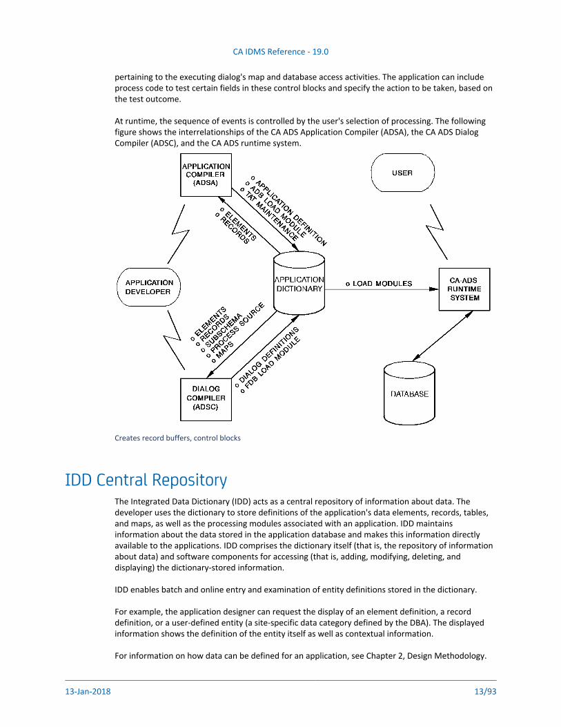
Accesses Record and Element DefinitionsThe CA ADS Application Compiler accesses record and element definitions stored in the dictionary. ADSA supplies the dictionary with the application definition; the updated Task Activity Table (TAT), the DC/UCF load module that associates task codes and the invoked tasks; and the Application Definition Block (ADB), the application load module. The CA ADS Dialog Compiler (ADSC) accesses record, element, subschema, map, and source process definitions stored in the dictionary. ADSC supplies the dictionary with the dialog definition and with the Fixed Dialog Block (FDB), the dialog load module. When the application is executed, the CA ADS runtime system accesses the application, dialog, map, subschema, and edit and code table load modules stored in the dictionary.
Creates Record Buffers and Control BlocksDuring dialog execution, the CA ADS runtime system dynamically creates record buffers for the subschema and dictionary records used by the dialog, and automatically initializes each field in the newly created buffers. The runtime system also creates control blocks that provide information
pertaining to the executing dialog's map and database access activities. The application can include
CA IDMS Reference - 19.0
13-Jan-2018 13/93
pertaining to the executing dialog's map and database access activities. The application can include process code to test certain fields in these control blocks and specify the action to be taken, based on the test outcome.
At runtime, the sequence of events is controlled by the user's selection of processing. The following figure shows the interrelationships of the CA ADS Application Compiler (ADSA), the CA ADS Dialog Compiler (ADSC), and the CA ADS runtime system.
Creates record buffers, control blocks
IDD Central RepositoryThe Integrated Data Dictionary (IDD) acts as a central repository of information about data. The developer uses the dictionary to store definitions of the application's data elements, records, tables, and maps, as well as the processing modules associated with an application. IDD maintains information about the data stored in the application database and makes this information directly available to the applications. IDD comprises the dictionary itself (that is, the repository of information about data) and software components for accessing (that is, adding, modifying, deleting, and displaying) the dictionary-stored information.
IDD enables batch and online entry and examination of entity definitions stored in the dictionary.
For example, the application designer can request the display of an element definition, a record definition, or a user-defined entity (a site-specific data category defined by the DBA). The displayed information shows the definition of the entity itself as well as contextual information.
For information on how data can be defined for an application, see Chapter 2, Design Methodology.
CA IDMS Reference - 19.0
13-Jan-2018 14/93
CA IDMS/DC Mapping FacilityThe CA IDMS/DC mapping facility is used to define the layout of the terminal screens (that is, maps) used for communication between the application and the user. A map definition, in addition to determining the appearance of the screen, associates fields on the screen (map fields) with record elements in the data dictionary, and defines display attributes (such as color and intensity) for map fields. All map definitions are stored in the dictionary.
Because maps are defined in the dictionary as separate entities, an CA ADS dialog can use a map simply by naming it on the appropriate CA ADS Dialog Compiler screen; the dialog itself does not perform any screen formatting.
At runtime, the mapping facility can perform automatic editing and error handling. When these facilities are enabled, input is validated automatically and output is formatted on the basis of dictionary-stored information on record elements (that is, internal picture, external picture, edit table, and code table). When a map is defined, the developer can specify different editing criteria for any field. The developer can also define stand-alone edit and code tables as modules in the dictionary. During map generation, these tables can be associated with map fields and external pictures can be defined for the fields.
For further information on the CA IDMS Online Mapping Facility and the automatic editing and error-handling capabilities available to the application, refer to .CA IDMS Reference section
Batch and Online Reporting FacilitiesThis section describes reporting capabilities that are available to the designer for assistance throughout the development process.
CA IDMS reportsProvides an extensive series of standard reports on information stored in the dictionary. These include summary, detail, and key reports of the elements and records in the dictionary. Reports are also available for dialogs and applications, and their associated components. Dictionary reports comprise a valuable tool for finding inconsistencies and redundant element types.For more information, see the .CA IDMS Reporting section
Subschema compilerEnables batch and online examination of subschema definitions.For further information on the use of the subschema compiler, see the CA IDMS Database
.Administration Guide
IDMSRPTS utilityProvides a series of reports on database definitions (for example, schema definitions, logical record definitions).For further information, including a complete list of the reports available with the IDMSRPTS utility, see the .CA IDMS Utilities Guide
CA OLQLets you interrogate an CA IDMS/DB and display and format the resulting information at a terminal. CA OLQ accommodates ad hoc queries. With the use of q-files (CA OLQ modules stored
in the dictionary), users can obtain formatted reports at the terminal simply by supplying the
CA IDMS Reference - 19.0
13-Jan-2018 15/93
in the dictionary), users can obtain formatted reports at the terminal simply by supplying the name of the desired q-file.For further information on using CA OLQ to query the dictionary and storing and accessing of q-files, see the .CA OLQ Using section
CA CulpritGenerates batch reports. CA Culprit is a parameter-driven system. CA Culprit actively uses dictionary-stored element, record, and subschema definitions. Reports can be packaged and stored as CA Culprit modules in the dictionary, enabling users to obtain a report simply by supplying the module name.For further information on the use of CA Culprit as an application reporting tool, see the CA
.Culprit for CA IDMS Using section
The dialog reporter (ADSORPTS utility)Requests batch reports that provide summary and/or detailed information about one or more dialogs. Reports can include: information on the records and processes of the named dialogs; a list of the contents of the Fixed Dialog Block (FDB); and a summary that includes map, schema, subschema, and version number information.For further information on the ADSORPTS utility, see the .CA ADS Reference section
The DC/UCF map utilityGenerates and deletes map load modules, produces map source code, and provides mapping reports. These reports display the decompiled source code, a list of the attributes assigned to each map field, and a list of the records used by the named map.For further information on using the map utility, see the .CA IDMS Reference section
The Design and Development TeamThe personnel involved in the development of an application reflect the range of responsibilities involved in the creation of a successful design. The manner in which these responsibilities are assigned varies widely from installation to installation, with some individuals often assuming more than one role.
The remainder of this section discusses the roles that should be included in the team that develops an application.
Project leaderOrchestrates and coordinates the project. The project leader is ultimately responsible for producing the system to specifications and on time.
DBA/DCAMaintains consistent site-specific standards. The DBA is responsible for the data resources (that is, the application database and the dictionary), designing and implementing the database records, defining the logical records, and establishing naming conventions and data dictionary standards. The DCA is involved in the network and communication needs, helping to plan for space requirements, performance, and system tuning.
CA IDMS Reference - 19.0
13-Jan-2018 16/93
Data administratorInterfaces with all members of the design and development team, running any reports that are needed as well as populating the dictionary. The data administrator is also responsible for enforcing the standards and conventions laid out by the DBA, entering the dictionary elements, records, maps, and edit and code tables as needed for the application.
Systems analystHelps analyze and document the needs of the end users. The analyst often works with the data administrator and also with the DBA in designing the database. Additionally, the analyst defines the requirements for the applications that will access the database.
ProgrammersWrites the processing logic that accesses the database, interpreting the dialog requirements given to them by analysts and designers. Working from design specifications, the programmer determines map data fields, field edits, map and work record elements, and the messages needed for a given dialog. This information is then submitted to the data administrator for approval and, subsequently, for inclusion in the dictionary. The dialog source code is written and stored in modules in the dictionary.
End usersProvides valuable input to the data administrator, DBA, systems analyst, and application programmers. They define what their present data needs are and try to predict future needs. There should be constant interaction between the end users and the other members of the development team, to ensure maximum usefulness of the applications developed.
CA IDMS Reference - 19.0
13-Jan-2018 17/93
1.
2.
3.
Design MethodologyThere are a number of ways to approach the design of a CA ADS application. The following topics present information about how data is defined and stored in the CA IDMS/DB environment.
Development of Effective Design (see page 17)Data Definition and Database Design Considerations (see page 36)
Note: The procedures represent one possible approach to a design and should be used as a guideline. Application developers must determine their system-specific needs and the design procedures that best meet those needs.
Development of Effective Design
Three PhasesThe sample approach to application design methodology that is presented throughout this manual comprises the following three phases:
Data definition -- The DBA and the systems analyst determine what element types the application needs. After defining the elements in the dictionary, the DBA then determines how the elements should be grouped into records and defines the records in the dictionary. As a result of this phase, the dictionary is populated with the element and record definitions required by the schema and subschema definitions, and with the application dialogs.
Database design and definition -- The project leader, with the help of the DBA, designs and defines the application database, creating a schema that reflects the data access needs of the application system as a whole (that is, all the programs in the application system); subschemas are then developed that reflect the data access needs of a specific application. The database design and definition phase also deals with the physical structure of the database (that is, how the database exists on disk storage). As a result of this phase, the schema, DMCL, and subschema are defined in the dictionary.
Application design and development -- The application development group designs and develops the applications. Dialogs are written using CA ADS process code, and dialog maps are created with the DC/UCF mapping facility. The CA ADS process code can link to routines written in source languages such as COBOL, PL/I, or Assembler. As a result of this third phase, applications exist in a form that end users can execute.
CA IDMS Reference - 19.0
13-Jan-2018 18/93
1.
2.
3.
4.
5.
How Tasks are PerformedThese phases can be implemented in chronological sequence, but they usually overlap, because certain tasks within each phase can be performed concurrently.
For example, an application prototype can be defined and executed while the database is being designed and data is being defined in the dictionary. However, each phase must be completed before the next phase can be fully implemented.
Five-Method DesignThe design method proposed in this manual is organized into the following five steps:
Analyzing the problem
Developing the design
Building a prototype
Writing process code for the dialogs
Testing and implementing the application
These steps are discussed in the following sections as well as a presentation of issues that underlie the entire design process.
Analyzing the ProblemContents
Team Approach (see page 18)How to Define the Need for the Application (see page 18)Developing Two Lists (see page 19)
Team ApproachProblem analysis involves defining end-user needs and agreeing upon the functional requirements of the application. To generate an effective application, it is essential to have the users involved as members of the team throughout the entire design and development process.
How to Define the Need for the ApplicationDuring this stage, the team seeks answers to questions that help define the need for the application. Information regarding the following is required:
Who is the end user?
CA IDMS Reference - 19.0
13-Jan-2018 19/93
What departments use these transactions?
Who performs a given activity?
What data does the user need to see?
What activities need to be automated?
How is the activity usually performed?
What information is referenced by these activities?
Where is the output information used?
What improvements are anticipated?
What types of reports will be needed? When are reports usually run?
How often will the application be used? By how many?
Developing Two ListsIn the process of analyzing the problem, develop the following lists:
Lists of activities that the user wants to be able to perform
Lists of information available to or necessary for the identified activities
Developing the DesignContents
DBA Incorporates Related Data (see page 19)External/Functional Specifications (see page 20)
Format Selection (see page 20)Identifying the Application Components (see page 20)How to Develop a Structural Diagram (see page 21)Returning to the Main Menu (see page 21)Documenting the Design (see page 23)
Internal/Technical Specifications (see page 24)Application Considerations (see page 24)
DBA Incorporates Related DataIn the second step, a design is created to meet the needs that have been identified. During the actual design process, information begins to fall into groups of related data that can be incorporated by the DBA into dictionary elements, records, schemas, subschemas, and logical records. At the same time, activities combine into predictable functions (for example, update, modify, delete) that logically work together and begin to form a step-by-step design.
CA IDMS Reference - 19.0
13-Jan-2018 20/93
When developing a design, the application and development group must consider the external/functional specifications and the internal/technical specifications. The external/functional specifications reflect the user's view of the application, indicating what functions will be performed by the application; the internal/technical specifications reflect the developer's view of the application, indicating how the application will operate. Each of these considerations is discussed separately below.
For the purposes of this manual, the discussion of the specifications assumes that the database has already been designed and that subschema views and other site-specific information have been obtained from the DBA.
External/Functional Specifications
Format Selection
Decisions need to be made about the format of the intended application. The developer must decide what activities will take place and the response choices that will be available to the user at each stage of the application.
Once the application components have been developed, it is helpful to develop a structural chart that depicts the application graphically. Finally, the design details need to be documented. Each of these stages is discussed below.
Identifying the Application Components
The following list suggests a few of the questions that need to be answered to establish relationships within and between the functions and responses that make up an application:
What online transactions need to be performed by the terminal user? For example, in the sample application, the user needs to be able to update the address, phone number, job code, or skill level of an employee.
What information or processing is needed before a given function can be implemented? For example, the appropriate employee record needs to be obtained from the database and displayed online before the record can be modified by the terminal user.
What are the possible results of a given function? For example, when the user chooses to update a record, will it be possible to delete the displayed record or can the record only be modified and stored?
After completing a function, what should be the next step? For example, will the application return to the menu screen after the employee record has been updated or will a new employee record be displayed? What response will the user have to make to effect either of these actions?
What relationships can be established between functions? For example, can the same map be used for both the update and browse functions?
How do these parts relate to the available or planned database entities? For example, is there a record in the database that provides information on the skill of an employee? If an employee has more than one skill or many employees have the same skill, will the application be able to access this information?
CA IDMS Reference - 19.0
13-Jan-2018 21/93
How to Develop a Structural Diagram
At this point in the design, it is useful to develop a graphic representation of the application, identifying the functions and responses, and incorporating them in a structural diagram that illustrates their interrelationships.
In addition to identifying the functions and responses of the application, the developer needs to be concerned with the following design items:
The number of levels the application will contain.
The commands that will be used to pass control between dialogs.
The system-provided functions (for example, POP, POPTOP, QUIT) that will be incorporated into the design.
The assignment of function keys and response codes.
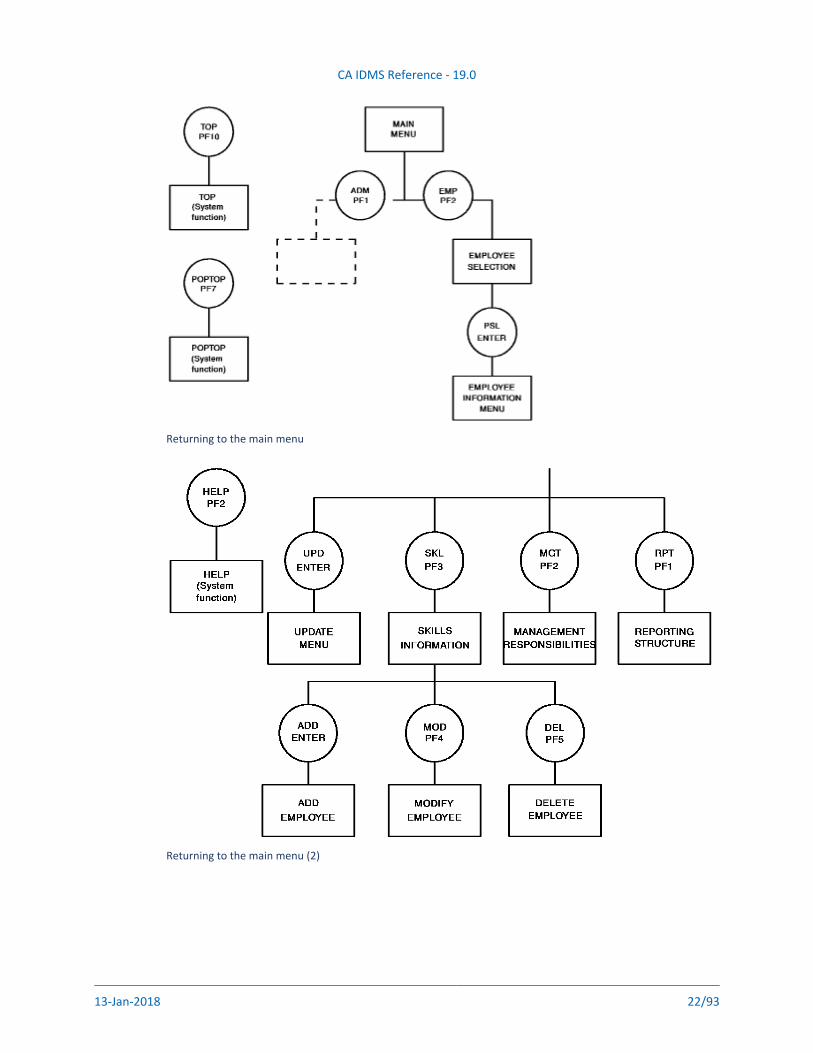
The diagram presents one way in which the developer can begin to sketch out the application and graphically depict the flow between functions and responses. The management information system being developed in this sample diagram has administrative and personnel applications; only the personnel application is represented in the flowchart. The user begins by selecting an application from the main menu. After obtaining the record on a particular employee, the user can select the appropriate response from the employee information menu to add, modify, and display the skills of the employee; obtain information on employee rank within the company's organizational structure; and update the personnel data on the employee.
Returning to the Main Menu
At any point, the user can use the system functions defined for this application to return to the main menu (POPTOP); display a screen that supplies the valid responses for the current function (HELP); or return to the previous function (TOP).
Before proceeding to the next step in the design and development of the application, the flowchart should be reviewed with end users and modified as necessary.
The following diagram illustrates the partial structuring of a sample management information system. The circles in the flowchart represent the application responses and the rectangles represent the functions. Within each circle is the response code and control key that will be defined to initiate the given function (for example, SKL/PF3 will initiate the display of information on employee skills). The system functions to be used in this application (that is, HELP, TOP, and POPTOP) are indicated.
CA IDMS Reference - 19.0
13-Jan-2018 22/93
Returning to the main menu
Returning to the main menu (2)
CA IDMS Reference - 19.0
13-Jan-2018 23/93
Documenting the Design
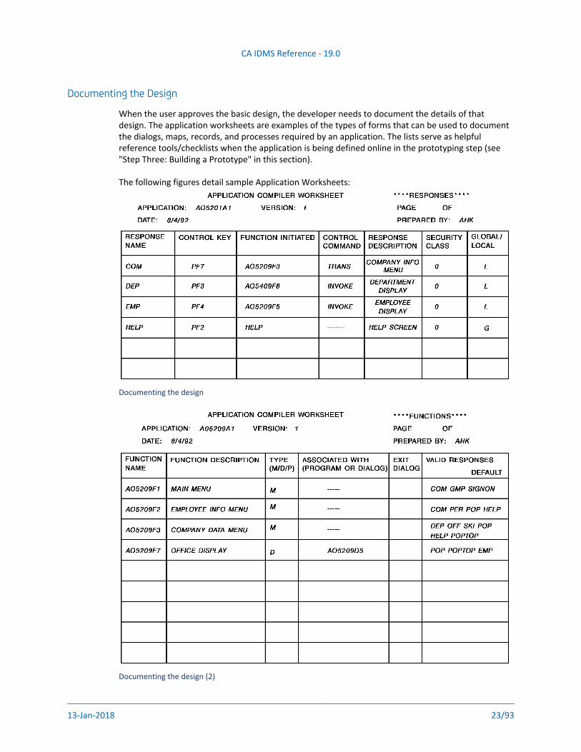
When the user approves the basic design, the developer needs to document the details of that design. The application worksheets are examples of the types of forms that can be used to document the dialogs, maps, records, and processes required by an application. The lists serve as helpful reference tools/checklists when the application is being defined online in the prototyping step (see "Step Three: Building a Prototype" in this section).
The following figures detail sample Application Worksheets:
Documenting the design
Documenting the design (2)
CA IDMS Reference - 19.0
13-Jan-2018 24/93
Charts or checklists, such as those shown in the previous graphic, also serve as excellent documentation for an application, because all pieces of the application, as well as their relationships, are detailed.
Additionally, the use of naming conventions is helpful: consistent use of naming standards makes it easier to keep track of application and dialog components as they are created and maintained.
For suggestions on the use of standard naming techniques, see Chapter 6, Naming Conventions.
Internal/Technical Specifications
Application Considerations
After the application format has been determined, decisions need to be made about how the application will work. The developer must consider the following:
Records -- What subschema, map, and work records are to be part of this application?
Menu Screens -- Will standard system-defined menus be used or will the menus be user-defined? If system-defined, which format of the system menu will be chosen? If user-defined, how will the menus be formatted and what will they do?For information about the three types of system-defined menu maps, see the CA IDMS Reference
.sectionChapter 4, Designing Maps discusses methods that can be used when designing user-defined menu maps.
Map formatting -- What maps will be needed? What will the maps look like? Are there site-specific standards that need to be considered?
Automatic editing -- What edit and/or code tables are necessary? Will the data be displayed as it is stored? How will the internal and external pictures be defined? How will the date display be formatted?For further information on automatic editing and error handling, see the CA IDMS Reference
.section
Messages -- What informational and error messages, other than those supplied by the runtime system, should be conveyed to the terminal user?
Security -- What levels of security will be assigned? Will user, program, or subschema registration be implemented? Will a user id and password be required to sign on to an application?For further information on the security that can be implemented, see the .CA ADS Using section
Building a Prototype (Effective Design)Contents
Uses for the Prototype (see page 25)Unique Features of the ADSA Builds Prototype (see page 25)How to Create the Prototype (see page 26)
Information required (see page 26)
CA IDMS Reference - 19.0
13-Jan-2018 25/93
An application prototype in an CA ADS environment is a representation of an online application system. As such, it is a tool that can be used throughout the design and development phases. Even after the implementation of an application, prototyping can be used as a vehicle for agreeing on revisions and enhancements.
Uses for a prototype, the unique features of a prototype, and creating a prototype are each discussed in the following sections.
Uses for the PrototypeThe prototype provides the following benefits:
Aids in the design process -- The prototype helps to build relationships between the basic information entities (data items, records) of the business application, and between the information entities and the activities to be automated (for example, online screens/transactions, reports, batch jobs).
Maximizes end-user participation -- The prototype provides an end-user view of the application from an early point in the development process. Most importantly, the users are actually seeing the prospective system online.Additionally, the user can participate in the step-by-step progress being made and can give valuable feedback while the application is still in its formative stage. As a review mechanism, the online screen walk-through provides a concrete means of checking to see if the application meets user needs.
Enhances project control -- The prototype provides an effective tool for monitoring the progress of the application development process.
Enables training -- The prototype can be used as a training tool for the data administrator and programmers on the development team. It enables them to become familiar with design techniques, dialog specifications, and documentation. The use of naming conventions, standardized coding procedures, and boilerplate process code facilitate the learning process. Additionally, the prototype can be employed by end users as a tool for training their own staff prior to implementation of the application in their production environment.
Establishes security procedures -- The prototype can incorporate the desired security standards without waiting for the source process code to be developed; thus, security procedures become established and understood by the end users at an early stage in the development of an application.
Provides an adaptable marketing tool -- A prototype can be developed as a demonstration model for use with prospective customers. As only a minimal amount of source code needs to be created, it is easy to adjust the prototype in response to specific user requests.
Unique Features of the ADSA Builds PrototypeThe prototype uses all the standard application components: dialogs that have been compiled with the CA ADS Dialog Compiler; maps that have been created with the DC/UCF system's mapping facility; and data elements that have been defined in the dictionary with DDDL statements. Most importantly, the prototype is built with the CA ADS Application Compiler.
ADSA provides the following capabilities that add considerable flexibility to the application, in general, and to dialogs, in particular:
CA IDMS Reference - 19.0
13-Jan-2018 26/93
1.
2.
3.
Security controls that can be put into effect for the application itself and for responses within the application
Standard menus that are automatically created by the system at runtime and allow the use of fewer dialogs
The EXECUTE NEXT FUNCTION command, which helps to control the flow of an application and allows process code to be more independent of its position within the application
Global records that enable the developer to use fewer levels in the application thread
Defined responses that reduce the number of response processes needed per dialog
Function-related task codes that facilitate multiple entry points into the application
Signon capabilities that make it possible for the end user to bypass the ENTER NEXT TASK CODE prompt from the DC/UCF system
How to Create the PrototypeA prototype application can be built in three stages, as follows:
Stage I: Building the basic prototype
Stage II: Adding process logic and data retrieval
Stage III: Refining the maps and processes
Each progressive stage contains enhancements that more closely approximate the final application. Note that it is possible to demonstrate the prototype online as soon as the first stage is completed successfully.
Information required
The developer must have the following information to format the prototype:
The screens needed to support the functional requirements
The processing activities taking place before and after communication with the user
The number of dialogs included in the application
The activities associated with each dialog
The manner in which processing selections will be made by the user
The control key and/or response code that will be associated with each selection
Worksheets can be developed to record all of the above information. Refer to the graphic, Sample Application Worksheets, earlier in this section for examples of sample worksheets. Chapter 3, Building a Prototype provides the step-by-step procedure for creating an online prototype.
CA IDMS Reference - 19.0
13-Jan-2018 27/93
Writing Process Code for the DialogsContents
Writing the Dialog Specifications (see page 27)Sample Template for Dialog Specifications (see page 27)Dialog Specifications Synopsis (see page 28)Guidelines for Dialog Specifications (see page 28)Reviewing the Specifications (see page 29)
Writing the Source Code (see page 29)Test Version Numbers (see page 29)Programming Aids (see page 29)Sample Premap Process Template 1 (see page 30)Sample Premap Process Template 2 (see page 31)What Templates Provide (see page 31)Sample Response Process Template (see page 31)Debugging Aids (see page 34)
Step Four is the stage at which the technical design is translated into specific dialogs that can be coded and unit tested. Writing the dialog specifications and writing the source code are each discussed separately.
Writing the Dialog SpecificationsBefore any code is written, it is necessary to write dialog specifications for each dialog defined in the technical design. This process can be standardized (and simplified) if the programmer has access to a template that provides the accepted format for these specifications. The following text illustrates an example of a template that a design team might develop for its programmers.
Sample Template for Dialog Specifications
*** HRIS SYSTEM ***
SPECIFICATION FOR DIALOG CEMDxxxx (...description of dialog...)
**************************************************************
* **** UPDATE LOG **** *
* WHO WHEN WHAT *
* === ==== ==== *
* MCS mm/dd/yy WROTE SPEC *
* MMC mm/dd/yy REVISED BASED ON NEW DATABASE DESIGN *
* *
* *
**************************************************************
DICTIONARY : DOCUNET
SCHEMA : EMPSCHM
SUBSCHEMA : EMPSS07
MAP : CEMMXXXX
MAP RECORD : CEMMXXXX-MAP-RECORD
DIALOG RECORD : CEMDXXXX WORK-RECORD, CEMDXXX-WORK2-RECORD
CA IDMS Reference - 19.0
13-Jan-2018 28/93
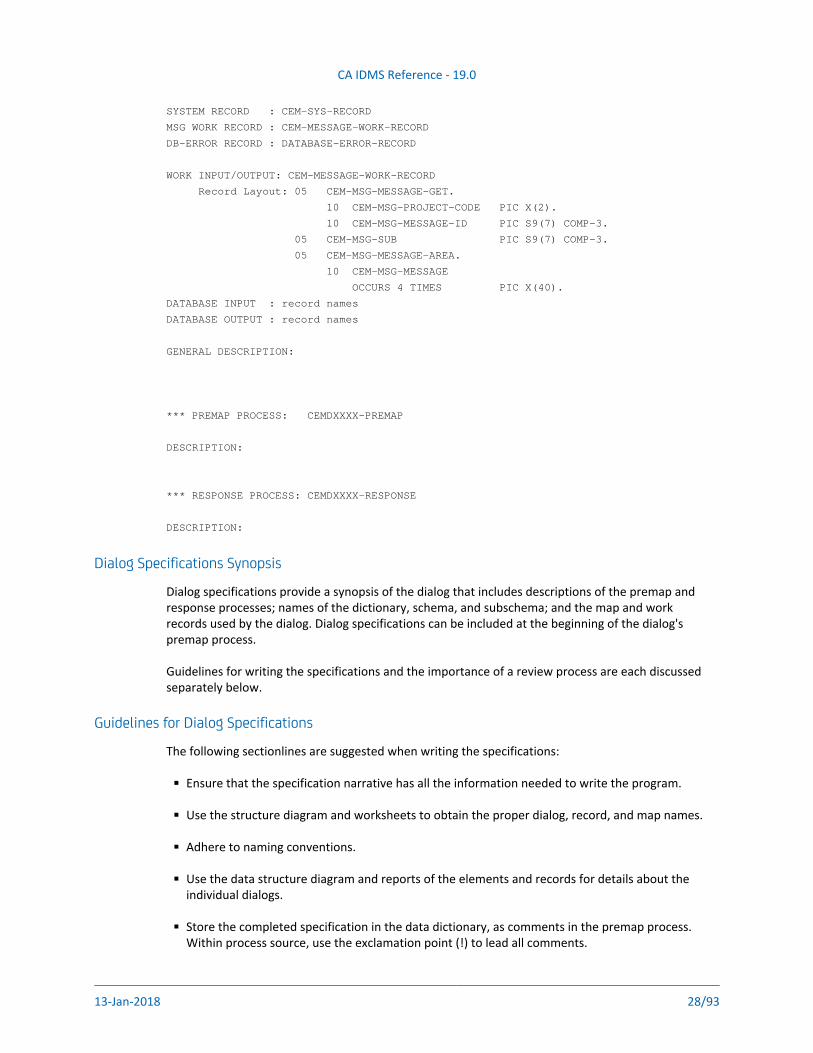
SYSTEM RECORD : CEM-SYS-RECORD
MSG WORK RECORD : CEM-MESSAGE-WORK-RECORD
DB-ERROR RECORD : DATABASE-ERROR-RECORD
WORK INPUT/OUTPUT: CEM-MESSAGE-WORK-RECORD
Record Layout: 05 CEM-MSG-MESSAGE-GET.
10 CEM-MSG-PROJECT-CODE PIC X(2).
10 CEM-MSG-MESSAGE-ID PIC S9(7) COMP-3.
05 CEM-MSG-SUB PIC S9(7) COMP-3.
05 CEM-MSG-MESSAGE-AREA.
10 CEM-MSG-MESSAGE
OCCURS 4 TIMES PIC X(40).
DATABASE INPUT : record names
DATABASE OUTPUT : record names
GENERAL DESCRIPTION:
*** PREMAP PROCESS: CEMDXXXX-PREMAP
DESCRIPTION:
*** RESPONSE PROCESS: CEMDXXXX-RESPONSE
DESCRIPTION:
Dialog Specifications Synopsis
Dialog specifications provide a synopsis of the dialog that includes descriptions of the premap and response processes; names of the dictionary, schema, and subschema; and the map and work records used by the dialog. Dialog specifications can be included at the beginning of the dialog's premap process.
Guidelines for writing the specifications and the importance of a review process are each discussed separately below.
Guidelines for Dialog Specifications
The following sectionlines are suggested when writing the specifications:
Ensure that the specification narrative has all the information needed to write the program.
Use the structure diagram and worksheets to obtain the proper dialog, record, and map names.
Adhere to naming conventions.
Use the data structure diagram and reports of the elements and records for details about the individual dialogs.
Store the completed specification in the data dictionary, as comments in the premap process. Within process source, use the exclamation point (!) to lead all comments.
CA IDMS Reference - 19.0
13-Jan-2018 29/93
If the specification is particularly long, store it as a separate module in the dictionary and copy it into the premap process code with an INCLUDE statement. In this way, the specifications are included in reports, but do not have to be viewed when the programmer is working on the source code.
Refer to maps by name and location. As the design of the dialog maps would have been completed when building the prototype, it is unnecessary to duplicate the layouts in the specifications. If further definitions on map fields are required in order to write the code, these definitions should be included in the specifications and given to the data administrator.
Incorporate other comments in the process source, as needed, especially at the beginning of response processes and subroutines. Batch programs and reports should also have their specifications included as comments within the code, unless the specifications are very long.
Some sites find it worthwhile to create a partitioned data set (PDS) or library for storing the specifications for each dialog. Such a data set can also be useful for central storage of the map templates and boilerplate code developed as programming aids.
Reviewing the Specifications
Coding should not begin until the project leader has reviewed and approved the dialog specifications. This is also the time to provide answers for questions that might have arisen during specification development. For example, in developing the specifications, it might become necessary to add some dialogs not already identified in the application structure. If so, this should be discussed and approved; changes can affect other screen layouts, as well as the manner in which the application has been defined to ADSA.
Writing the Source CodeOnce the specifications have been approved, the programmer can write the source code. The use of test version numbers, procedures to aid the programmer, and dialog debugging aids are each discussed separately below.
Test Version Numbers
The DC/UCF system provides facilities for establishing a runtime environment in which test and production copies of the same application components can execute under one system. Programmers can be assigned a unique version number to be used when generating their own versions of maps, edit and code tables, and dialogs. When the application is fully tested and working, the version number can be changed for production purposes.
For a detailed discussion of the preparations necessary when establishing a test environment, refer to .CA IDMS System Reference section
Programming Aids
To improve the efficiency of the development process and to help maintain standards, an installation might institute some of the following procedures for the programming staff:
Create templates of dialog premap and response processes. The programmer can obtain a copy of the template, rename it, and add the specific dialog logic.
Provide a list of the standard (site-specific) work records that are to be used by each dialog.
CA IDMS Reference - 19.0
13-Jan-2018 30/93
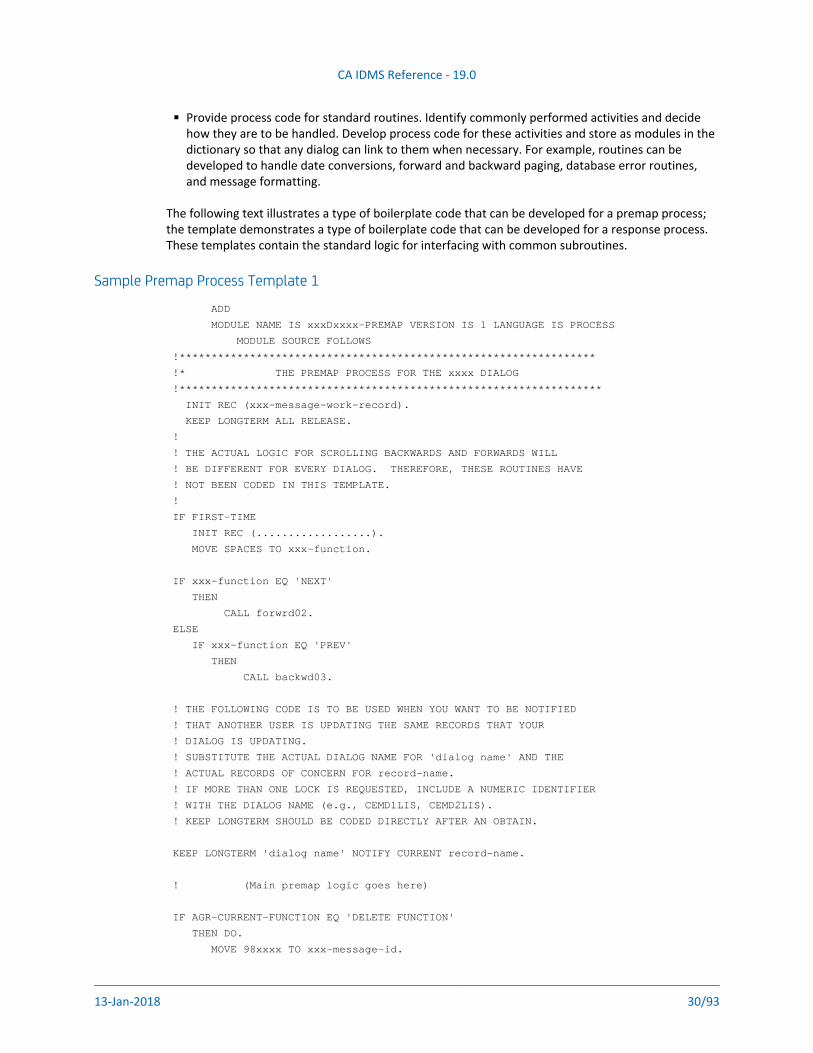
Provide process code for standard routines. Identify commonly performed activities and decide how they are to be handled. Develop process code for these activities and store as modules in the dictionary so that any dialog can link to them when necessary. For example, routines can be developed to handle date conversions, forward and backward paging, database error routines, and message formatting.
The following text illustrates a type of boilerplate code that can be developed for a premap process; the template demonstrates a type of boilerplate code that can be developed for a response process. These templates contain the standard logic for interfacing with common subroutines.
Sample Premap Process Template 1
ADD
MODULE NAME IS xxxDxxxx-PREMAP VERSION IS 1 LANGUAGE IS PROCESS
MODULE SOURCE FOLLOWS
!*****************************************************************
!* THE PREMAP PROCESS FOR THE xxxx DIALOG
!******************************************************************
INIT REC (xxx-message-work-record).
KEEP LONGTERM ALL RELEASE.
!
! THE ACTUAL LOGIC FOR SCROLLING BACKWARDS AND FORWARDS WILL
! BE DIFFERENT FOR EVERY DIALOG. THEREFORE, THESE ROUTINES HAVE
! NOT BEEN CODED IN THIS TEMPLATE.
!
IF FIRST-TIME
INIT REC (..................).
MOVE SPACES TO xxx-function.
IF xxx-function EQ 'NEXT'
THEN
CALL forwrd02.
ELSE
IF xxx-function EQ 'PREV'
THEN
CALL backwd03.
! THE FOLLOWING CODE IS TO BE USED WHEN YOU WANT TO BE NOTIFIED
! THAT ANOTHER USER IS UPDATING THE SAME RECORDS THAT YOUR
! DIALOG IS UPDATING.
! SUBSTITUTE THE ACTUAL DIALOG NAME FOR 'dialog name' AND THE
! ACTUAL RECORDS OF CONCERN FOR record-name.
! IF MORE THAN ONE LOCK IS REQUESTED, INCLUDE A NUMERIC IDENTIFIER
! WITH THE DIALOG NAME (e.g., CEMD1LIS, CEMD2LIS).
! KEEP LONGTERM SHOULD BE CODED DIRECTLY AFTER AN OBTAIN.
KEEP LONGTERM 'dialog name' NOTIFY CURRENT record-name.
! (Main premap logic goes here)
IF AGR-CURRENT-FUNCTION EQ 'DELETE FUNCTION'
THEN DO.
MOVE 98xxxx TO xxx-message-id.
CA IDMS Reference - 19.0
13-Jan-2018 31/93
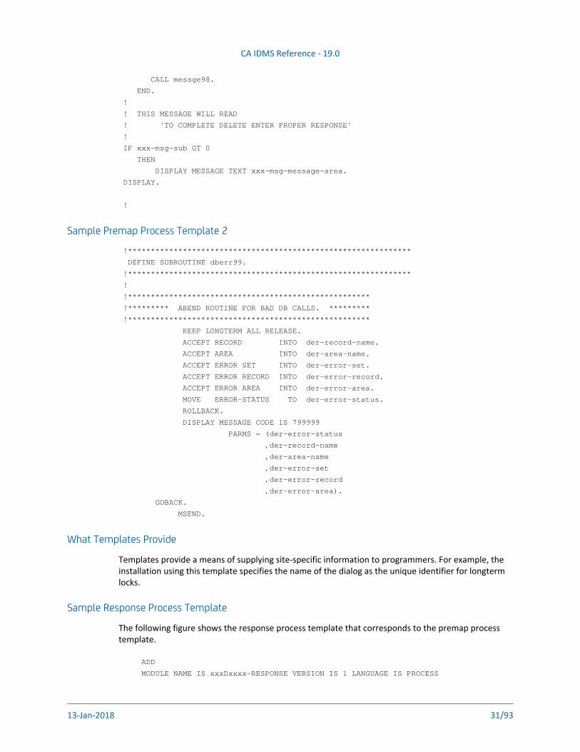
CALL messge98.
END.
!
! THIS MESSAGE WILL READ
! 'TO COMPLETE DELETE ENTER PROPER RESPONSE'
!
IF xxx-msg-sub GT 0
THEN
DISPLAY MESSAGE TEXT xxx-msg-message-area.
DISPLAY.
!
Sample Premap Process Template 2
!**************************************************************
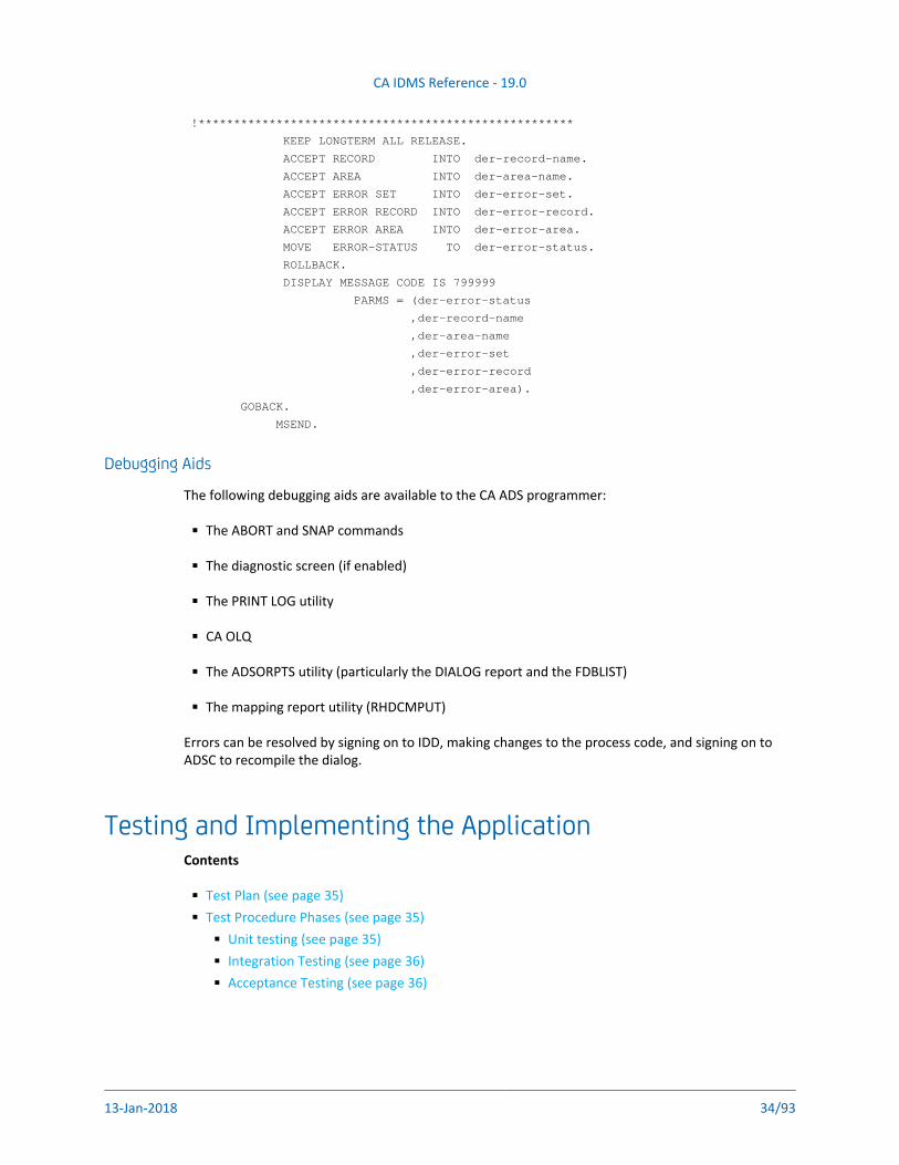
DEFINE SUBROUTINE dberr99.
!**************************************************************
!
!*****************************************************
!********* ABEND ROUTINE FOR BAD DB CALLS. *********
!*****************************************************
KEEP LONGTERM ALL RELEASE.
ACCEPT RECORD INTO der-record-name.
ACCEPT AREA INTO der-area-name.
ACCEPT ERROR SET INTO der-error-set.
ACCEPT ERROR RECORD INTO der-error-record.
ACCEPT ERROR AREA INTO der-error-area.
MOVE ERROR-STATUS TO der-error-status.
ROLLBACK.
DISPLAY MESSAGE CODE IS 799999
PARMS = (der-error-status
,der-record-name
,der-area-name
,der-error-set
,der-error-record
,der-error-area).
GOBACK.
MSEND.
What Templates Provide
Templates provide a means of supplying site-specific information to programmers. For example, the installation using this template specifies the name of the dialog as the unique identifier for longterm locks.
Sample Response Process Template
The following figure shows the response process template that corresponds to the premap process template.
ADD
MODULE NAME IS xxxDxxxx-RESPONSE VERSION IS 1 LANGUAGE IS PROCESS
CA IDMS Reference - 19.0
13-Jan-2018 32/93
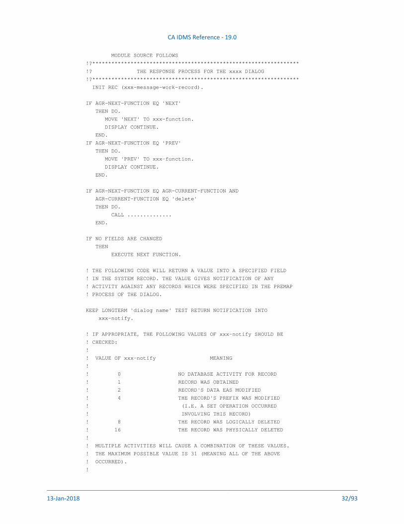
MODULE SOURCE FOLLOWS
!?*****************************************************************
!? THE RESPONSE PROCESS FOR THE xxxx DIALOG
!?*****************************************************************
INIT REC (xxx-message-work-record).
IF AGR-NEXT-FUNCTION EQ 'NEXT'
THEN DO.
MOVE 'NEXT' TO xxx-function.
DISPLAY CONTINUE.
END.
IF AGR-NEXT-FUNCTION EQ 'PREV'
THEN DO.
MOVE 'PREV' TO xxx-function.
DISPLAY CONTINUE.
END.
IF AGR-NEXT-FUNCTION EQ AGR-CURRENT-FUNCTION AND
AGR-CURRENT-FUNCTION EQ 'delete'
THEN DO.
CALL ..............
END.
IF NO FIELDS ARE CHANGED
THEN
EXECUTE NEXT FUNCTION.
! THE FOLLOWING CODE WILL RETURN A VALUE INTO A SPECIFIED FIELD
! IN THE SYSTEM RECORD. THE VALUE GIVES NOTIFICATION OF ANY
! ACTIVITY AGAINST ANY RECORDS WHICH WERE SPECIFIED IN THE PREMAP
! PROCESS OF THE DIALOG.
KEEP LONGTERM 'dialog name' TEST RETURN NOTIFICATION INTO
xxx-notify.
! IF APPROPRIATE, THE FOLLOWING VALUES OF xxx-notify SHOULD BE
! CHECKED:
!
! VALUE OF xxx-notify MEANING
!
! 0 NO DATABASE ACTIVITY FOR RECORD
! 1 RECORD WAS OBTAINED
! 2 RECORD'S DATA EAS MODIFIED
! 4 THE RECORD'S PREFIX WAS MODIFIED
! (I.E. A SET OPERATION OCCURRED
! INVOLVING THIS RECORD)
! 8 THE RECORD WAS LOGICALLY DELETED
! 16 THE RECORD WAS PHYSICALLY DELETED
!
! MULTIPLE ACTIVITIES WILL CAUSE A COMBINATION OF THESE VALUES.
! THE MAXIMUM POSSIBLE VALUE IS 31 (MEANING ALL OF THE ABOVE
! OCCURRED).
!
CA IDMS Reference - 19.0
13-Jan-2018 33/93
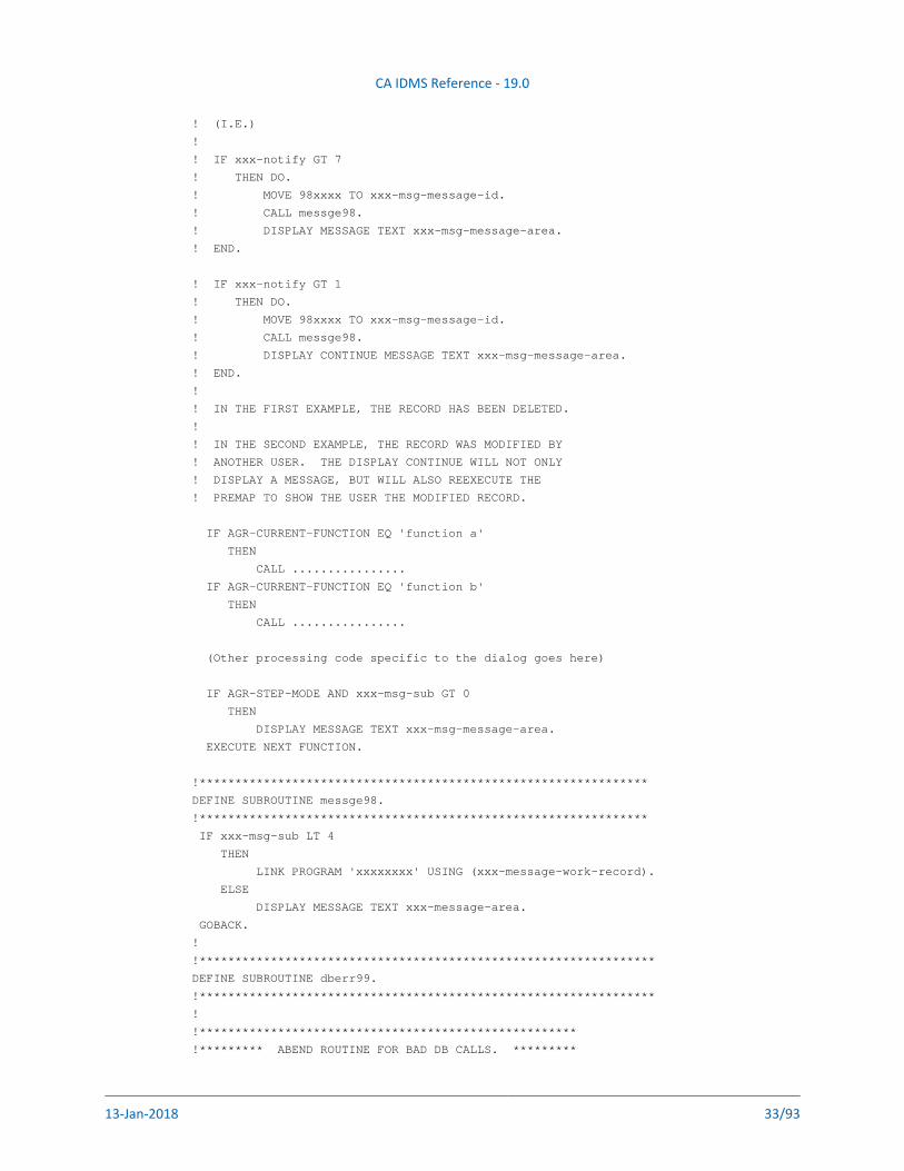
! (I.E.)
!
! IF xxx-notify GT 7
! THEN DO.
! MOVE 98xxxx TO xxx-msg-message-id.
! CALL messge98.
! DISPLAY MESSAGE TEXT xxx-msg-message-area.
! END.
! IF xxx-notify GT 1
! THEN DO.
! MOVE 98xxxx TO xxx-msg-message-id.
! CALL messge98.
! DISPLAY CONTINUE MESSAGE TEXT xxx-msg-message-area.
! END.
!
! IN THE FIRST EXAMPLE, THE RECORD HAS BEEN DELETED.
!
! IN THE SECOND EXAMPLE, THE RECORD WAS MODIFIED BY
! ANOTHER USER. THE DISPLAY CONTINUE WILL NOT ONLY
! DISPLAY A MESSAGE, BUT WILL ALSO REEXECUTE THE
! PREMAP TO SHOW THE USER THE MODIFIED RECORD.
IF AGR-CURRENT-FUNCTION EQ 'function a'
THEN
CALL ................
IF AGR-CURRENT-FUNCTION EQ 'function b'
THEN
CALL ................
(Other processing code specific to the dialog goes here)
IF AGR-STEP-MODE AND xxx-msg-sub GT 0
THEN
DISPLAY MESSAGE TEXT xxx-msg-message-area.
EXECUTE NEXT FUNCTION.
!***************************************************************
DEFINE SUBROUTINE messge98.
!***************************************************************
IF xxx-msg-sub LT 4
THEN
LINK PROGRAM 'xxxxxxxx' USING (xxx-message-work-record).
ELSE
DISPLAY MESSAGE TEXT xxx-message-area.
GOBACK.
!
!****************************************************************
DEFINE SUBROUTINE dberr99.
!****************************************************************
!
!*****************************************************
!********* ABEND ROUTINE FOR BAD DB CALLS. *********
CA IDMS Reference - 19.0
13-Jan-2018 34/93
!*****************************************************
KEEP LONGTERM ALL RELEASE.
ACCEPT RECORD INTO der-record-name.
ACCEPT AREA INTO der-area-name.
ACCEPT ERROR SET INTO der-error-set.
ACCEPT ERROR RECORD INTO der-error-record.
ACCEPT ERROR AREA INTO der-error-area.
MOVE ERROR-STATUS TO der-error-status.
ROLLBACK.
DISPLAY MESSAGE CODE IS 799999
PARMS = (der-error-status
,der-record-name
,der-area-name
,der-error-set
,der-error-record
,der-error-area).
GOBACK.
MSEND.
Debugging Aids
The following debugging aids are available to the CA ADS programmer:
The ABORT and SNAP commands
The diagnostic screen (if enabled)
The PRINT LOG utility
CA OLQ
The ADSORPTS utility (particularly the DIALOG report and the FDBLIST)
The mapping report utility (RHDCMPUT)
Errors can be resolved by signing on to IDD, making changes to the process code, and signing on to ADSC to recompile the dialog.
Testing and Implementing the ApplicationContents
Test Plan (see page 35)Test Procedure Phases (see page 35)
Unit testing (see page 35)Integration Testing (see page 36)Acceptance Testing (see page 36)
CA IDMS Reference - 19.0
13-Jan-2018 35/93
The final stage of application design and development deals with the testing and implementation of the application. This is an important step that requires careful planning. Testing should not begin until a comprehensive test plan has been formulated; the testing itself should be thoughtfully structured.
Guidelines for developing a test plan and the procedures involved in the final testing of an application are discussed in the following sections.
Test PlanA definitive test plan should be drawn up after the technical design is finalized. This plan is particularly important when performing acceptance testing for the user because it must reflect the expectations of the user. The plan should include the following information:
Division of the application for testing purposes
Plans for testing interfaces
The order of testing, taking into account the planned implementation
Approval criteria for user and operations acceptance of the system
Test data to be used and the method of creating this data
Operational and technical support required
A list of all testing and related tasks
The people involved and their specific responsibilities
A schedule for testing and acceptance of the system
Test Procedure PhasesProcedures for testing applications typically fall into the following phases:
Unit testing by the programmer
Integrated system testing by the programming team
User acceptance testing
Each of these phases is described in the following sections.
Unit testing
Each dialog should be tested in isolation for all possible error conditions. This should be done either by the person who developed the dialog, or, preferably, by another member of the project team. The following lists should be drawn up beforehand:
The conditions to be tested
The data used to test these conditions
CA IDMS Reference - 19.0
13-Jan-2018 36/93
The data used to test these conditions
The expected results
The documented results of the testing should be approved by the project leader. When the unit testing is completed successfully, the dialog should be submitted for subsystem or integration testing. For dialogs that operate independently, no testing should be required beyond unit testing.
Integration Testing
Integration testing determines whether the dialogs within each subsystem are functioning in accordance with the specifications. Interdependent dialogs should be grouped together and tested as a unit, using the same principle as for unit testing. To avoid duplication of effort, this phase should use the same data as that used for unit testing whenever possible. The application, in its entirety, should be tested to ensure that all paths through the application are traversed correctly.
Regression testing is a useful practice to implement. Test results are saved from each of the test procedures to be compared with subsequent test results if/when changes are made to an application. Comparison of the test results can provide an efficient way to monitor the effectiveness of the changes.
Acceptance Testing
Users determine the acceptance test criteria and should approve all system outputs. Acceptance testing ensures that the system is functionally acceptable to the users and will operate successfully in the production environment. Testing should be performed using live or simulated-live data provided by the users.
Data Definition and Database Design Considerations
Because CA ADS operates in the CA IDMS/DB environment, it is important to review how data is defined and stored in that environment. In a traditional application development environment, the application programs comprise both processing logic and information about the data accessed. Processing logic, which determines the action taken by a program to produce the desired output, correctly belongs in the realm of programming. Defining information about data (such as the format of records and elements, and editing criteria) can be handled more easily and efficiently as a separate function.
The CA IDMS/DB environment uses the dictionary to accomplish this separation of information about data from process logic. The dictionary maintains information about data and makes this information directly available to the application maps and dialogs that need it.
Advantages of Separating Information (see page 37)Definition of Information (see page 37)
CA IDMS Reference - 19.0
13-Jan-2018 37/93
Advantages of Separating InformationSeparating information about data from process logic has the following advantages:
Allows control of data resources -- The site has better control over data resources because the control is centralized. Centralized control provides the following benefits:
Eliminates unwanted data redundancy
Controls the data that is available
Determines where data elements are used and by whom
Establishes standards for data element names, input and output formats, and editing criteria
Facilitates the design, development, and maintenance of CA ADS applications -- The application can use data from the dictionary and can store application-specific data in the dictionary where it can be maintained. The data can be accessed by a variety of reporting facilities and software components, and can be populated and updated automatically.
Increases productivity -- Productivity is increased because activities are not duplicated. Information about an element type is defined once and does not have to be defined separately by every programmer using that element in a dialog or map.The DBA staff can concentrate on defining information for the applications, and the programming staff can concentrate on the processing logic. For example, the dictionary can maintain editing and display information for each element. The DBA can simply define in the dictionary that the external format of social security numbers is 999-99-999, and the application programmers need not be concerned about editing and formatting the element when they use it. On all input operations for this element, the automatic editing facility will verify that user input conforms to this picture; on all output operations, it will format the data and insert hyphens. Defining the elements in this way is easier, less error prone, and less time consuming than coding process logic.
Definition of InformationThe definition of information for an application can be divided into the following two phases:
Data definition
Database design and definition
Each of these phases in the design process is outlined below.
For further information on this topic, see the .CA IDMS Database Design Guide
CA IDMS Reference - 19.0
13-Jan-2018 38/93
1.
2.
3.
Building a PrototypeThe development of a prototype can be approached in a variety of ways, depending upon the needs of the design team. The procedures suggested in this topic are based on the following three-stage approach:
The first stage performs rudimentary navigation of the application
The second stage begins to perform data retrieval and update.
The third stage incorporates refinements that reflect the more complex requirements of an application running in a production environment.
Each stage is discussed in the following articles:Building the Basic Prototype (see page 38)Adding Process Logic and Data Retrieval (see page 41)Refining the Maps and Processes (see page 43)
Building the Basic PrototypeBuilding the basic prototype is the first stage of the three-stage approach to building a prototype. The first stage details how to build the prototype and the benefits of doing so.
The following topics are discussed on this page:
Prototype Can Be Developed Quickly (see page 38)Activities to Perform (see page 39)How to Compile the Application (ADSA) (see page 39)Compiling the Maps (see page 40)Compiling the Dialogs (ADSC) (see page 40)User Review (see page 41)
Prototype Can Be Developed QuicklyThe first stage of the prototype can be developed quickly and easily because only skeletal maps and dialogs are needed for execution by the CA ADS runtime system. Typically, maps are created with just enough information to identify their use in the application process, and one dialog is created for each map. The dialogs do not need a premap process or a response process. With a minimum of time and effort, the designer has the opportunity to see how the application is going to work even before data processing takes place.
CA IDMS Reference - 19.0
13-Jan-2018 39/93
1.
2.
3.
1.
2.
3.
4.
5.
Activities to PerformTo build an executable prototype, the developer needs to provide load modules for the runtime system by performing the following activities:
Compiling the application -- The application and its components (the functions and responses) are defined and compiled with ADSA.
Compiling the maps -- Each map is formatted, defined, and compiled with the online mapping facility.
Compiling the dialogs -- Each dialog is identified, associated with the appropriate map, and compiled with ADSC.
The prototype can be executed when the application, map, and dialog load modules are available for use by the CA ADS runtime system. At this point, the developer has a meaningful version of the prototype that can be presented for user review and modification.
Each of the activities for building the basic prototype is discussed separately below, followed by user review considerations.
How to Compile the Application (ADSA)The amount of detail provided for a prototype can be as extensive as the developer wishes, but the basic prototype does not have to be elaborate. After initiating an ADSA session, the developer can define and compile an application as follows:
Specify the application -- ADSA must be supplied the name of the application and related information such as version number.
Name the task code -- The task code designates an entry point into the application. If there are multiple entry points, each task code must be defined individually.
Define the responses -- The responses that initiate the functions of the application must be specified.
Define the functions -- Menu and dialog functions that are initiated by the responses must be specified.
Note: Every function that you define as a dialog function in ADSA you must also define to ADSC as a dialog.
Compile the application.
CA IDMS Reference - 19.0
13-Jan-2018 40/93
1.
2.
3.
1.
2.
3.
4.
When the above-named activities are completed successfully, ADSA defines an Application Definition Block (ADB) for the application and updates the Task Activity Table. Both the ADB and the TAT are stored as load modules in the dictionary and are used by the CA ADS runtime system when the application is executed.
Compiling the MapsHow to Produce Prototype Screens
Maps that are compiled for the first stage of the prototype usually contain all literal fields. The developer signs on to the online mapping facility (MAPC) and takes the following steps to produce the prototype screens:
Specify the map and map options -- The map name and related information such as version number must be supplied to MAPC. Certain options, such as display options, may also be appropriate to specify for the prototype.
Produce a screen layout -- A layout can be produced automatically if the developer specifies existing dictionary records to MAPC. Otherwise, the layout can be produced manually. Literal values (such as hyphens or underscores) can be assigned to represent variable data fields.
Compile the map -- A map load module is stored in the DDLDCLOD area of the dictionary when the map has been compiled successfully.
Compiling the Dialogs (ADSC)Compile a Dialog for Each Map
You must compile one dialog for each map used by the prototype.
To compile a prototype dialog
Initiate an ADSC session
Add the dialog.
Associate the map with the dialog.
Compile the dialog.
ConsiderationsThe following considerations should be noted when compiling dialogs for an application:
If a dialog is defined as a function in ADSA, it must be defined in ADSC.
If a dialog is associated with a task code, it must be defined as a mainline dialog.
The associated map must be compiled before the dialog can be compiled.
CA IDMS Reference - 19.0
13-Jan-2018 41/93
The associated map must be compiled before the dialog can be compiled.
ADSC defines a Fixed Dialog Block (FDB) for every dialog that is compiled successfully. The FDB is stored as a load module in the dictionary and is used by the CA ADS runtime system when the application is executed.
User ReviewAfter the application, map, and dialog load modules have been compiled, the prototype is ready to be presented to the user for careful online review. Modifications based on review should be made to the existing prototype, the necessary load modules recompiled, and the prototype resubmitted for review until the users are satisfied.
Adding Process Logic and Data RetrievalThe prototype becomes more functional in this second stage. The developer might add activities such as the following to the prototype:
Global records (ADSA)
Security restrictions such as signon menus (ADSA)
Display capabilities (online mapping and IDD)
Premap and response process logic (ADSC and IDD)
The following topics are discussed on this page:
ADSA Enhancements (see page 41)Populating the Dictionary (see page 42)CA IDMS Mapping Facility Enhancements (see page 42)ADSC Enhancements (see page 42)
ADSA EnhancementsThe following ADSA features can be added to the prototype at this point:
Global records (that is, records that are available for use by all dialogs in the application) can be defined
User-program records (that is, records that are to be passed to a user-program) can be defined if needed
Valid responses listed for a function can be resequenced or their display can be suppressed
Signon can be specified as required or optional. If either is specified, these steps must be taken:
The signon function must be identified
CA IDMS Reference - 19.0
13-Jan-2018 42/93
The signon function must be identified
The function type of the signon function must be specified as menu
The function must be defined as a menu
The SIGNON system function must be specified as the function initiated by the user's response from the signon screen
The response that initiates the SIGNON system function must be specified as a valid response for the named menu function
When these changes have been made, recompile the application.
Populating the DictionaryThe dictionary must contain the following three components if they are to be used by the prototype:
Dialog premap and response processesPremap and response processes must be stored as process modules in the dictionary. If premap or response processes are associated with a dialog, process modules must be defined in the dictionary before the dialog can be compiled. Modules are added to the dictionary with the IDD MODULE statement specifying LANGUAGE IS PROCESS.
Map records and dialog work recordsAll work records used by a dialog and all records associated with maps must be defined in the dictionary before the dialogs and maps can be compiled. Similarly, an application cannot be compiled unless all global records associated with the application are defined in the dictionary. Records are added with the IDD RECORD statement.
Edit and code tablesAll stand-alone edit and code tables associated with map records must be defined in the dictionary before the map is compiled. Edit and code tables are added with the IDD TABLE statement.
CA IDMS Mapping Facility EnhancementsVariable map fields that were defined as literals for the first stage of the prototype should be redefined as data fields and edited accordingly. When the appropriate enhancements have been made, the map should be recompiled.
ADSC EnhancementsThe developer now uses ADSC, recompiling the dialog to include the premap and response processes, as well as the changes made to the map associated with this dialog. After initiating an ADSC session and naming the appropriate dialog, the develop can make these enhancements:
Database specification -- Specify the database that the dialog accesses
CA IDMS Reference - 19.0
13-Jan-2018 43/93
Work records -- Supply the names of all work records associated with the dialog
Note: If the dialog is using subschema records, they must belong to the same subschema as the dialog.
Premap process -- Supply the name of the premap process associated with the dialog.
Response process -- Supply the name of the response process associated with the dialog and a control key and/or response field value unique to that response process.
Recompile the dialog after making the appropriate enhancements.
Refining the Maps and ProcessesThe final stage of prototype development can focus on refinement of the map design and the map field attributes. Some of the following additions can be made:
Incorporate additional fields in the maps
Add or change map field attributes
Specify automatic editing on selected map fields
Provide informational messages
Add error messages
CA IDMS Reference - 19.0
13-Jan-2018 44/93
Designing Maps
Determining Success of an ApplicationMaps displayed during the execution of the application interface directly with the user and, therefore, can influence the success of an application. Consequently, the designer must consider the appearance of the menu screens and the layout of the dialog maps.
A successful map design should exhibit the following attributes:
Consistency -- Entities (for example, fields, headings, labels, responses, messages, and control keys) should have the same meaning or effect throughout the application. The meaning or effect need not be identical for every map, but should be consistent within the broader confines of the system. In general, there are two special fields on any screen: a message field and a response code field. These areas should appear in a constant location on the screen throughout any application; for maximum effectiveness, they should remain standard for all applications at a site.
Convenience -- Features of the system should be designed to associate related entities by using similar constructs, positioning, and responses to produce similar reactions from the system. For example, assign one particular control key to initiate the update function in all the dialogs of a given application.
Supportiveness -- The reactions of the system should enable the user to handle normal contingencies conveniently. Tutorial aids should be available when needed. Displayed informational and/or error messages should be meaningful.
The remainder of this section discusses the following aspects of map design:Online Mapping Procedures (see page 44)Choosing Menu Maps (see page 45)Designing Dialog Maps (see page 48)
Online Mapping ProceduresThe following list details the mapping procedures that might be implemented by a specific site:
Have one individual (for example, the data administrator) responsible for creating and modifying all maps.
As much as possible, use the features of the online mapping facility to handle editing, error handling, error messages, and modifying field attributes.
Use a standard map template. Whenever possible, keep data fields in columns and double space rows of data.
CA IDMS Reference - 19.0
13-Jan-2018 45/93
Use the BRIGHT attribute to contrast items on the screen that have different uses (for example, highlight required fields). Be consistent in the use of attributes.
Use the cursor in a consistent manner. For example, either place the cursor at the first field to be used for data entry or at the field where the user is to enter the next function.
Use the BRIGHT attribute for redisplaying data fields that are in error.
Choosing Menu MapsContents
Available Menu Map Types (see page 45)System-Defined Menu Maps (see page 45)
Designer's options (see page 45)User-Defined Menu Maps (see page 46)
Altering Map Methods (see page 46)Reformat the System-Defined Menu (see page 46)Regenerating the System-Defined Menu (see page 46)Design a Menu/Dialog (see page 47)
Available Menu Map TypesWhen designing an application, the developer needs to decide if system- or user-defined menu mapsare to be used. The system-defined menu provides a standard format for the information provided by the developer during the definition of the functions and responses of the application in an ADSA session. If a format other than the standard format is desired (for example, the developer wishes to redefine certain literal fields on the map or wants to supply site-specific headers), the user-defined menu map is used. Both types of maps are discussed separately below.
System-Defined Menu MapsDesigner's options
If the menu map is to be system-defined, the designer has the option of using one of the following menu formats:
Short description menu map (ADSOMUR1) -- The menu screen that lists 30 valid menu responses per page; a short (12-byte) textual description is displayed for each response.
Long description menu map (ADSOMUR2) -- The menu screen that lists 15 valid menu responses per page; a long (28-byte) textual description is displayed for each response name.
Signon menu map (ADSOMSON) -- The menu screen that requires a DC/UCF validation of user id and password before the menu request can be processed. The standard signon menu map can have 12 valid menu response names per page with 28 bytes of descriptive text displayed for each.
CA IDMS Reference - 19.0
13-Jan-2018 46/93
1.
2.
3.
If none of the these menus meets the needs of the user, the system-defined menu map can be altered by the user or a new menu (designated as a menu/dialog function) can be formatted. Both methods of creating user-defined maps are discussed in the following sections.
User-Defined Menu MapsAltering Map Methods
When user-specific modifications to the existing system-defined menu maps are necessary, designers can alter the menu maps by using either of the following techniques:
Reformatting and regenerating the standard system-defined menu
Designing a menu/dialog (that is, a menu map that is part of a menu/dialog function)
Each of these methods is discussed in the following sections.
Reformat the System-Defined MenuThe existing system-designed menu map can be reformatted and regenerated, retaining the same name. This method has the advantage of allowing the developer to use the standard menu function rather than designing and using a menu/dialog function.
To reformat the system menu
Obtain the source for the map being used (that is, ASDSOMUR1, ADSOMUR2, or ADSOMSON) from the source data sets created when the distribution tape was installed. The maps are stored as members under their own names.
Use the batch mapping compiler to store the source in the dictionary.
Use the online mapping facility to modify and regenerate the menu map.
Regenerating the System-Defined MenuWhen regenerating a menu map with the online mapping facility, the following rules must be observed:
ADSO-APPLICATION-MENU-RECORD is a required map record. Optionally, the menu can map to additional records, but it must always map to the .hw ADSO--APPLICATION--MENU--RECORD.
The menu must contain the same number of responses per page as the number of responses for the selected map (that is, 30 for ADSOMUR1, 15 for ADSOMUR2, or 12 for ADSOMSON).
The AMR-RESPONSE field of the .hw ADSO--APPLICATION--MENU--RECORD record is a required field. The first response name on the map must map to the first occurrence of AMR-RESPONSE. Each subsequent response name must map to the next corresponding occurrence.
CA IDMS Reference - 19.0
13-Jan-2018 47/93
1.
2.
3.
4.
The AMR-USER-ID and AMR-PASSWORD fields of the .hw ADSO--APPLICATION--MENU--RECORD are required on a signon menu map. The user id data field must map to AMR-USER-ID, and the password data field must map to AMR-PASSWORD.
All other fields on the .hw ADSO--APPLICATION--MENU--RECORD are optional. The map data fields that are used must be associated with the appropriate fields on the record (for example, heading data must map to AMR-HEADING).
If using the AMR-KEY field, note that this field appears as a single byte (the AID byte) in the .hw ADSO--APPLICATION--MENU--RECORD. The AMR-KEY field is associated with a code table (ADSOAIDM) that translates the AID byte to more easily readable characters (for example, 1 translates to PF1, percentage translates to PA1).
For more information on using online mapping facility to regenerate a map, refer to CA IDMS .Reference section
Design a Menu/DialogThe user has the option of designing and generating an entirely new menu with the online mapping facility. This map must be defined as a menu/dialog function of the application.
To design a menu/dialog function
Design and generate the map using the online mapping facility. Observe the following rules when generating the map:
ADSO-APPLICATION-MENU-RECORD must be one of the records associated with the map.
The AMR-RESPONSE field is required for all menus. The number of required occurrences depends on the number of responses per page (to a maximum of 50) specified on the ADSA Menu Specification screen. The first response name on the map must map to the first occurrence of AMR-RESPONSE; each subsequent occurrence must map to the next corresponding occurrence of AMR-RESPONSE.
The AMR-USER-ID and AMR-PASSWORD fields are required for signon maps. The user id data field must map to AMR-USER-ID, and the password data field must map to AMR-PASSWORD.
All other fields on the .hw ADSO--APPLICATION--MENU--RECORD are optional. The map data fields used must be associated with the appropriate fields on the record (for example, heading data must map to AMR-HEADING).
Add the process source to the dictionary in an IDD session. (The dialog associated with the menu does not have to include any process code, although the choice of a menu/dialog function suggests that some processing is intended.)
Compile the dialog in an ADSC session, associating the map and any processes with the dialog using the ADSC Dialog Definition screen. Note that the dialog must be compiled to include the map before the application can be executed at run time.
Define the dialog as a menu/dialog function for the application.
An installation can develop standard map templates and the associated boilerplate code for site-
CA IDMS Reference - 19.0
13-Jan-2018 48/93
An installation can develop standard map templates and the associated boilerplate code for site-specific menu/dialogs. When a menu is needed, programmers can obtain a copy of the template/boilerplate, fill in the appropriate fields and the edit/code tables needed for those fields, and submit it to the data administrator for approval.
Designing Dialog MapsContents
Design Dialog Questions (see page 48)Standardizing Formats (see page 48)Sample Template for an Application Screen (see page 49)
Design Dialog QuestionsEach dialog map is associated with its own dialog and must be designed to reflect the function of the associated dialog. The application specifications developed during the initial design stages can be used to answer design questions such as the following:
How many of the dialogs specified for this application will require maps?
What premap and response processes are required for each map?
What job is performed by each process?
Will the map be used to pass data between processes and/or between dialogs? What data will be passed?
What database and mapping work records are associated with the map?
What editing criteria should apply to the map fields?
Standardizing FormatsJust as site-specific standards can be established for menu/dialogs, an installation can use map templates to standardize the formatting of maps associated with dialog functions. Programmers can obtain a copy of the template; fill in the appropriate fields, indicating the corresponding map record fields; and submit this information to the data administrator. The data administrator can then add the necessary map design, map records, and edit/code tables (if any) to the dictionary.
The following figure illustrates a sample map template that can be provided for programmers. This template designates standard areas for headers, footers, message codes and descriptions, response areas, and the passing data field. The installation using this template has written a routine that divides the message area into four 40-character messages.
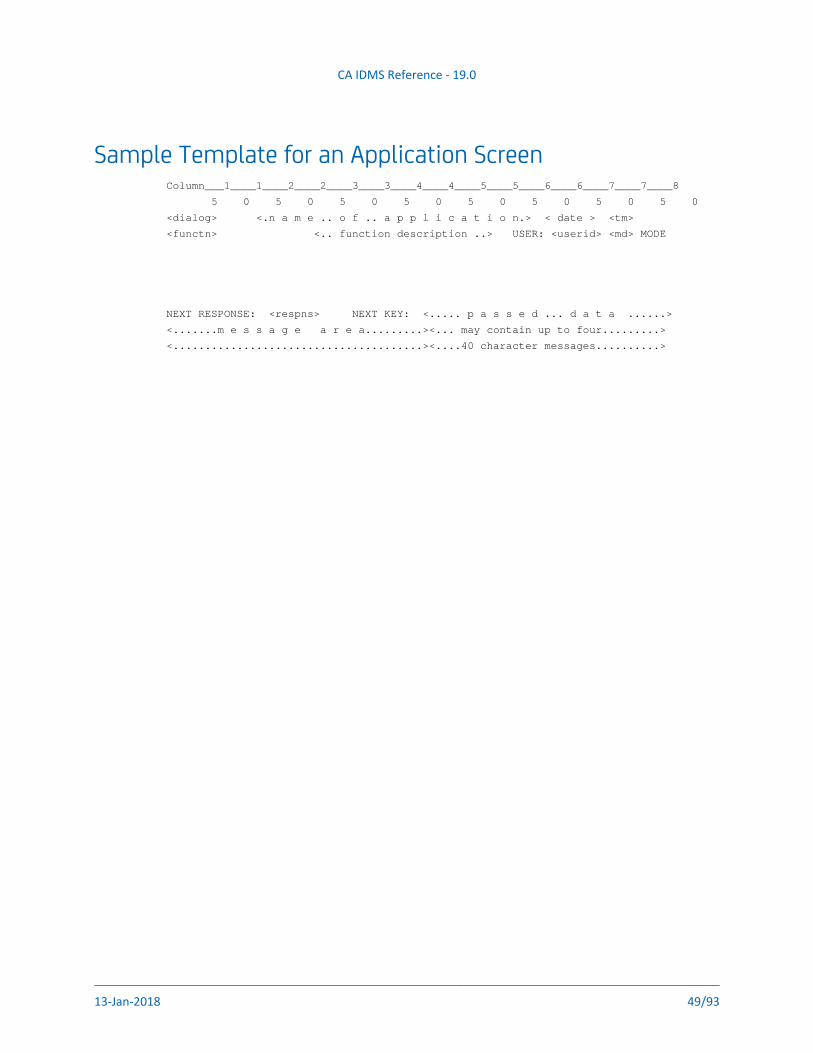
CA IDMS Reference - 19.0
13-Jan-2018 49/93
Sample Template for an Application ScreenColumn___1____1____2____2____3____3____4____4____5____5____6____6____7____7____8
5 0 5 0 5 0 5 0 5 0 5 0 5 0 5 0
<dialog> <.n a m e .. o f .. a p p l i c a t i o n.> < date > <tm>
<functn> <.. function description ..> USER: <userid> <md> MODE
NEXT RESPONSE: <respns> NEXT KEY: <..... p a s s e d ... d a t a ......>
<.......m e s s a g e a r e a.........><... may contain up to four.........>
<.......................................><....40 character messages..........>
CA IDMS Reference - 19.0
13-Jan-2018 50/93
Designing DialogsA dialog is a unit of work within an CA ADS application that enables interaction with the user. Because dialogs are the basic building blocks of an CA ADS application, it is important that they be well-designed. This section discusses characteristics and design features of dialogs that merit the attention of application developers.
Contents
Dialog Characteristics (see page 50)Dialog Level (see page 50)
Developer's Role (see page 50)Aspects Influenced (see page 51)
Dialog Status (see page 51)Dialog Types (see page 51)Sequence of Dialog Execution (see page 52)
Dialog Control (see page 52)Passing control to another dialog (see page 52)
Dialog CharacteristicsThe characteristics of a dialog determine its role within the application; each dialog has an implicit level and status, and can pass and receive control of the processing. The significance of the dialog level and status and the manner in which control is passed are discussed the following sections.
Dialog Level
Developer's RoleThe level of a dialog refers to its position within the application structure. The application developer can pass processing control to a dialog at the next lower level, the same level, the next higher level, or the top level of the application structure.
Note: The meaning of TOP changes whenever a LINK command is executed. The dialog issuing LINK becomes the current TOP.
CA IDMS Reference - 19.0
13-Jan-2018 51/93
Aspects InfluencedAt runtime, the dialog level affects the following aspects of an application:
Availability of data -- When combined with the manner in which processing control is received, the level of a dialog governs the data passed in the record buffer blocks and the currencies that are established, saved, stored, or released.
Use of system resources -- The runtime system maintains record buffer blocks, database currency blocks, and variable dialog blocks for dialogs at each level. There is a direct correlation between the number of dialog levels in an application and the size of the storage pool that is needed.
Performance -- The number of dialog levels can affect the performance of an application. For example, performance times are affected if a frequently accessed dialog is located three or four levels down in an application structure.
An application can be composed of any number of dialog levels, but the most efficient application uses many levels only when absolutely necessary.
The top-level dialog must be a dialog and must be defined as such by the application mainlinedeveloper. A mainline dialog is the entry point to the application. An application can have more than one mainline dialog; entry points can also be established at a lower level in the application structure. In addition to defining a task code for the top-level dialog, the developer can identify an alternative entry point by using the Task Definition screen to associate a task code with a lower-level function.
Dialog Status
Dialog TypesA dialog can have an or a status within the application thread. A dialog operative nonoperativebecomes operative when it receives control and begins executing; at a given level, only one dialog can be operative at a time.
When control passes to a dialog at another level, the issuing dialog can remain operative or can become nonoperative, depending upon the level of the next dialog. For example, when control is passed with the LINK command, the issuing dialog remains operative; when control is passed with the TRANSFER command, the issuing dialog becomes nonoperative.
As long as a dialog is operative, all data that it has acquired is retained. When a dialog becomes nonoperative, its data is released. See the table, later in this section, that summarizes the way in which a dialog's status is affected by the successful execution of a control command.
CA IDMS Reference - 19.0
13-Jan-2018 52/93
1.
2.
3.
4.
5.
Sequence of Dialog ExecutionWithin the application structure, only one dialog executes at a time. The sequence of dialog execution within an application structure is called the . The response of the user application threaddetermines the dialogs that constitute a given application thread.
One dialog can exist in several places within the application structure and be part of the same or different application threads. A dialog can execute more than once within the application thread whether or not it remains operative.
Dialog Control
Passing control to another dialogA dialog passes control to another dialog based on the execution of a control command and/or the user's selection of processing. The dialog that receives control can be a different dialog, a copy of the executing dialog, or all or part of the executing dialog itself.
The application developer can use specific control commands to perform the following operations:
Pass processing control from one dialog to another dialog or to a user program.
Display a dialog's map.
Terminate an existing dialog or application.
Exit CA ADS.
Pass processing control to specified points within a dialog and reinitialize the record buffers associated with a dialog.
Most of the control commands used are available to all applications. When designing dialogs that will become part of an application that is compiled in an ADSA session, the developer can also use the EXECUTE NEXT FUNCTION command.
For a discussion of the commands that direct the flow of control within an application, see Application Concepts. This section also contains a diagram and discussion of how the runtime system determines the order in which the functions of an application are executed.
For more information, see the following topics:Design Considerations (see page 53)Dialogs That Issue Navigational DML (see page 61)
CA IDMS Reference - 19.0
13-Jan-2018 53/93
Design ConsiderationsThe application developer needs to keep the following CA IDMS/DB, DC/UCF, and CA ADS system features in mind when designing the dialogs:
Record Buffer Management (see page 53)Working Storage Areas (see page 55)Global Records (see page 57)
Record Buffer ManagementWhat Affects Record Buffer Management
At the beginning of each application thread, the CA ADS runtime system allocates a primary Record Buffer Block (RBB) and initializes a buffer in the RBB for each record associated with the top-level dialog. All lower-level dialogs can access records in any of the existing buffers, unless one of the following conditions is true:
The dialog that receives control accesses a record that has been assigned the NEW COPY attribute during dialog generation.
The dialog that receives control accesses a record not used by a higher-level dialog.
The dialog that receives control issues navigational DML statements to access an LRF (Logical Record Facility) record within a subschema not used by a higher-level dialog.
If one or more of these conditions exist, CA ADS allocates and initializes an additional buffer for the record.
Additional buffers are also allocated and initialized when one of the following situations exists:
The record is assigned the WORK RECORD attribute during dialog generation.
The record is associated with the map used by the dialog.
The record is named explicitly in a database command.
Record Buffer AllocationThe following example illustrates the sequence in which CA ADS initializes record buffers as a series of dialogs receives control.
When dialog A begins executing, CA ADS allocates buffers for the EMPLOYEE and SKILL record types. Dialog B uses the previously allocated EMPLOYEE record buffer, but requires a new buffer for the OFFICE record. Dialog C requests and receives a new copy of the EMPLOYEE record buffer, but uses the previously allocated SKILL record buffer. Dialog D requires new buffers for both the DEPARTMENT and JOB records. CA ADS allocates a secondary RBB to accommodate the DEPARTMENT record, but uses the remaining space in the primary RBB for the JOB record.
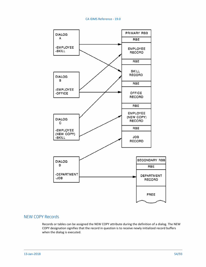
CA IDMS Reference - 19.0
13-Jan-2018 54/93
NEW COPY RecordsRecords or tables can be assigned the NEW COPY attribute during the definition of a dialog. The NEW COPY designation signifies that the record in question is to receive newly initialized record buffers when the dialog is executed.
CA IDMS Reference - 19.0
13-Jan-2018 55/93
The NEW COPY attribute is used when the programmer wants to obtain another occurrence of a record type without overwriting the data that is in the current buffer. To have the use of a second, temporary buffer for the same record type, the programmer links to a lower-level dialog that has specified NEW COPY for that record. An occurrence of the record type is brought into the new buffer and processed as directed. When control returns to the calling dialog, the record buffer at the upper level contains the same data as before; the data in the lower-level record buffer is no longer available.
Dialogs at a level lower than the dialog with a NEW COPY record will not use the NEW COPY buffer, but will use the first buffer allocated for the record.
Working Storage AreasQueue and Scratch Areas
The DC/UCF system queue and scratch areas can be used by the CA ADS dialogs as working storage areas. The methods by which dialogs can store and use records in the queue and scratch areas are presented below.
Queue RecordsQueue records can be used as work records that are shared by tasks on all DC/UCF system terminals. Entries are directed to a queue with database commands embedded in the dialogs or batch programs. Queues can transfer data across the entire DC/UCF system and are maintained across system shutdowns and crashes. Currencies and locks are not passed between tasks.
Note: When used in a sysplex environment, the queue area may be shared between multiple DC/UCF systems. For more information on shared queues, please see the CA IDMS
manual.System Reference section
Queue records have the following characteristics:
A queue header record is allocated either at system generation or by an application dialog.
Queue records participate in a set in the dictionary; this set is commonly referred to as a queue.
Queue records are locked by each task; no other task can use them until the locks are released.
Queues created at system generation with the system QUEUE statement can be accessed by an CA ADS application. Additionally, an application can create its own queues by requesting storage space with a GET QUEUE statement in the dialog process code.
An application can use queue records to accomplish the following functions:
CA IDMS Reference - 19.0
13-Jan-2018 56/93
1.
2.
3.
Automatically initiate a task -- The DC/UCF system initiates a task that processes the queue entries when the number of entries in a queue reaches a specified limit or when a specified time interval has passed. For example, an application can write records to a queue and the system will route the records to a printer when the collected records exceed the specified limit.
Avoid prime time updating -- Records that need to be updated can be collected on a queue; the queue can be accessed by a batch program at a low-use time.
Prevent run-away tasks -- A maximum limit can be established for the number of entries permitted in a queue. The UPPER LIMIT parameter of the QUEUE statement is especially useful in a test environment to prevent a looping program from filling the scratch/queue area.
Scratch RecordsScratch records are shared between tasks and saved across the transactions of an CA ADS application. Used as a temporary storage area, scratch records provide a means of passing data between tasks running on the same terminal; they are not accessible to tasks that execute on other terminals and are not saved across a system shutdown or a system crash.
The following characteristics are associated with scratch records:
Scratch records are stored in the dictionary.
Multiple scratch areas are allowed for a task and multiple records can be maintained within a scratch area.
Currency is maintained for each area and record, and can be passed between tasks.
The scratch area is allocated dynamically within the storage pool. When all scratch records are deleted, the area will also be deleted.
Scratch records can be used in the following ways within an application:
To save input acquired from two or more dialogs over the course of the application.
To allow multiple occurrences of a record to be mapped out at one time. For example, if the names, addresses, and phone numbers of all department employees need to be mapped onto the same screen in multiples of five, the following steps could be taken:
Walk the set of employee records, moving the required data to a work record that contains multiply-occurring fields.
When the work record contains the data on five employees, move the contents of the work record to the scratch area with a PUT SCRATCH command so that, in effect, a screenful of data on five employees is put on each record in the scratch file.
Walk the set of scratch records when the screens of information are to be displayed.
To pass the contents of the record buffer when a dialog receives control with a TRANSFER command. Data acquired by the dialog issuing a TRANSFER command is not available to the dialog receiving control. However, the dialog receiving control could access buffer data that had been placed in a scratch record.
CA IDMS Reference - 19.0
13-Jan-2018 57/93
Global RecordsGlobal records are records that are available to all dialogs, maps, and user programs in an application. Subschema records cannot be defined as global records.
The ADSO-APPLICATION-GLOBAL-RECORD is the system-defined global record that enables communication between the application and the runtime system. To be accessed by a dialog, the ADSO-APPLICATION-GLOBAL-RECORD must either be specified as a dialog work record or be associated with the dialog's map. This record is initialized when an application is first loaded by the runtime system.
All fields in the .hw ADSO--APPLICATION--GLOBAl--RECORD are addressable by dialogs or user programs.
Selected FieldsSelected fields from the .hw ADSO--APPLICATION--GLOBAl--RECORD are listed below.
The AGR-NEXT-FUNCTION field contains the name of the next function that is to be executed. When the dialog associated with the current function ends with an EXECUTE NEXT FUNCTION command, the function named in the AGR-NEXT-FUNCTION field is executed by the runtime system. A dialog or user program can query this field to check what the next function will be. Modification of the AGR-NEXT-FUNCTION field, however, does not change the next function to be executed; a change in the next function can only be accomplished by modification of the AGR-CURRENT-RESPONSE field (see below).
The AGR-DEFAULT-RESPONSE field contains the default response value specified on the Function Definition screen when an application is generated. When a value is specified and the screen includes a data field for a default response, the user can type in a new value or can space out the value that appears.
The AGR-CURRENT-RESPONSE field contains the response specified by the user. The process code of a dialog or user program can also move values into this field, overwriting the user response. Note that, if .hw AGR--CURRENT--RESPONSE is modified by a dialog, security is not checked for the response moving into the field, even if security is associated with this response.
When EXECUTE NEXT FUNCTION is encountered within process code, the response named in the AGR-CURRENT-RESPONSE field is executed if it is a valid response for the current function. The AGR-CURRENT-RESPONSE field determines the next function in the application thread (that is, it determines the value moved into the AGR-NEXT-FUNCTION field).
The value in AGR-CURRENT-RESPONSE depends upon whether the AGR-DEFAULT-RESPONSE field contains a value; whether the user enters a new value in the response field; or whether there is a response value associated with the control key (other than ENTER) pressed by the user.
The following flowchart illustrates how the CA ADS runtime system places a value in the AGR-CURRENT-RESPONSE field of the .hw ADSO--APPLICATION--GLOBAL--RECORD. The runtime system executes the response named in the AGR-CURRENT-RESPONSE field after determining that it is a valid response for the current function.
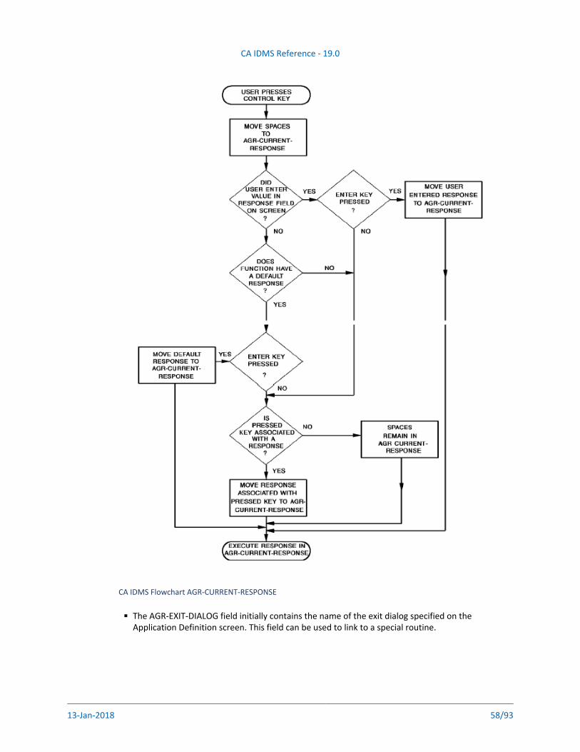
CA IDMS Reference - 19.0
13-Jan-2018 58/93
CA IDMS Flowchart AGR-CURRENT-RESPONSE
The AGR-EXIT-DIALOG field initially contains the name of the exit dialog specified on the Application Definition screen. This field can be used to link to a special routine.
CA IDMS Reference - 19.0
13-Jan-2018 59/93
For example, one department of a company might want the employee name specified as John Doe, while another department wants the name specified as Doe, John. The same dialog could be used for both departments by linking to an exit dialog (that is, LINK TO AGR-EXIT-DIALOG) containing a name routine.
The AGR-PRINT-DESTINATION field initially contains the default name of the printer for the application as specified on the ADSA Application Definition screen. Dialogs and user programs can use this print destination with the WRITE PRINTER DESTINATION command.
The AGR-USER-ID field can be queried by dialogs and user programs.
The AGR-PRINT-CLASS field initially contains the default printer class for the application as specified on the ADSA Application Definition screen. The dialog can reference this field with the WRITE PRINTER CLASS command.
The AGR-SIGNON-SWITCH field can be queried to determine if there has been a valid signon.
The AGR-SIGNON-REQMTS field indicates whether signon is optional, required, or not used for the signon menu, as specified on the Security screen. This field can be referenced for additional security checking.
The AGR-MAP-RESPONSE field can be used as a response field, in place of the $RESPONSE field, in any user-defined nonmenu map. The dialog can initialize this response field before mapout so that the desired default response appears on the map. For input purposes, the AGR-MAP-RESPONSE field works in the same manner as the $RESPONSE field.
For further information on the $RESPONSE field, refer to CA IDMS Reference section
The AGR-MODE field initially contains the value STEP or FAST as specified on the Application Definition screen. Typically, the design of a dialog map includes a field that displays the value of AGR-MODE. The user can change this field at any time.
AGR-MODE Field ExamplesIn the following text, two examples of how the AGR-MODE field can be used are presented, with the EXECUTE NEXT FUNCTION command, to implement a STEP/FAST mode for an ADSA application. The logic in the first example assumes that all data field validation is handled by the automatic editing specifications in the dialog's map. The logic in the second example assumes that additional data validation is required in the response process code. In both cases, any data entered by the user is always processed. Note that the first pass flag field has no significance in FAST mode.
Using the AGR-MODE-field (example 1)IF ANY OF (EMPLOYEE-NBR, SKILL-CODE, SKILL-LEVEL)
ARE CHANGED
DO.
MOVE 'Y' TO FIRST-PASS-FLAG.
MOVE EMPLOYEE-NBR TO WK-EMPNBR.
MOVE SKILL-CODE TO WK-SKLCODE.
MOVE SKILL-LEVEL TO WK-SKLEVEL.
LINK TO 'CEMDUEMP'.
END.
CA IDMS Reference - 19.0
13-Jan-2018 60/93
IF AGR-STEP-MODE
DO.
IF FIRST-PASS-FLAG='Y'
DO.
MOVE 'N' TO FIRST-PASS-FLAG.
DISPLAY MSG TEXT IS 'EMPLOYEE UPDATED'.
END.
MOVE 'Y' TO FIRST-PASS-FLAG.
END.
EXECUTE NEXT FUNCTION.
The preceding sample process code illustrates the manner in which a dialog can query the AGR-MODE field of the .hw ADSO--APPLICATION--GLOBAL--RECORD to determine what course to follow. If the dialog is in STEP mode, the dialog redisplays the screen with a confirmation message for the user; if in FAST mode, control is passed immediately to the next function. The initial value of AGR-MODE is supplied by the runtime system; the user can alter the value of AGR-MODE at any time during application execution.
Using the AGR-MODE field (example 2)IF ANY OF (EMPLOYEE-NBR, SKILL-CODE, SKILL-LEVEL)
ARE CHANGED
DO.
MOVE 'Y' TO FIRST-PASS-FLAG.
IF EMPLOYEE-NBR GE 2000 AND SKILL-CODE='A'
DO.
MOVE 'Y' TO ERROR-FLAG.
DISPLAY MSG TEXT IS
'EMPLOYEE NUMBER/SKILL CODE MISMATCH'.
END.
MOVE 'N' TO ERROR-FLAG.
MOVE EMPLOYEE-NBR TO WK-EMPNBR.
MOVE SKILL-CODE TO WK-SKLCODE.
MOVE SKILL-LEVEL TO WK-SKLEVEL.
LINK TO 'CEMDUEMP'.
CALL EMPDTE25.
END.
IF ERROR-FLAG='Y'
DISPLAY MSG TEXT IS
'EMPLOYEE NUMBER/SKILL CODE MISMATCH'.
CALL EMPDTE25.
!**************************************************
DEFINE EMPDTE25.
!**************************************************
IF AGR-STEP-MODE
DO.
IF FIRST-PASS-FLAG='Y'
DO.
MOVE 'N' TO FIRST-PASS-FLAG.
DISPLAY MSG TEXT IS 'EMPLOYEE UPDATED'.
END.
MOVE 'Y' TO FIRST-PASS-FLAG.
END.
CA IDMS Reference - 19.0
13-Jan-2018 61/93
EXECUTE NEXT FUNCTION.
The sample code shown in the preceding figure illustrates the use of the AGR-MODE field when data validation needs to be handled by code in the response process. Note that the EXECUTE NEXT FUNCTION command is never encountered while uncorrected validation errors still exist.
Mapping to ScreensThe following fields from the .hw ADSO--APPLICATION--GLOBAL--RECORD are often mapped to screens associated with user-defined, non-menu maps:
AGR-DIALOG-NAME
AGR-APPLICATION-NAME
AGR-CURRENT-FUNCTION
AGR-FUNCTION-DESCRIPTION
AGR-DATE
AGR-USER-ID
AGR-MODE
AGR-PASSED-DATA
AGR-MAP-RESPONSE
For an illustration of how these fields can be used on maps, see .Designing Maps (see page 44)
Dialogs That Issue Navigational DMLContents
Database Currencies How Currency is Maintained (see page 62)The Effects of Control Commands (see page 62)
Extended Run Units (see page 63)Longterm Locks (see page 64)Record Buffer Management for Logical Records (see page 65)
Additional design considerations apply to dialogs that issue navigational DML commands. These considerations are as follows:
Database currencies
Extended run units
Longterm locks
Record buffer management for logical records
CA IDMS Reference - 19.0
13-Jan-2018 62/93
1.
2.
3.
4.
Database Currencies How Currency is MaintainedIn CA ADS, currency is maintained automatically for the user. To facilitate this feature, a currency control block is created that maintains currency information. At run time, a currency block is created for each dialog in the application structure that performs database requests.
Database currencies are passed from one dialog to another dialog at a lower level, enabling dialogs to continue database processing from an established position in the database. Currencies are cumulative. The currencies established by each dialog are passed to lower-level dialogs, which, in turn, establish their own currencies; the cumulative currencies are passed to the next lower-level dialog.
Currencies are established, saved, restored, and released as follows:
Established -- Currency is established with the dialog's first functional database call. Established currencies are updated when database commands (for example, FIND, OBTAIN, ERASE) are encountered during the run unit. Currency is nulled when a dialog receives control with a RETURN or TRANSFER command.
Saved -- When a LINK, DISPLAY, or INVOKE command is issued, the database currencies established with the last database command in the dialog are saved. Saved currencies are available to lower-level dialogs and are restored to the issuing dialog if processing control returns.
Restored -- Saved currencies are restored when CA ADS opens a run unit in the dialog receiving control (that is, saved currencies are restored just prior to the first database call).
Released -- When a LEAVE, RETURN, or TRANSFER command is issued, all database currencies at the same and lower levels are released. The dialog receiving control must establish its own currencies or use the currencies passed to it from another higher-level dialog.
The successful execution of control commands can affect the operative or nonoperative status of a dialog, the dialog's acquired data that is retained or released, and the currencies that are saved, restored, or released.
The Effects of Control CommandsThe following table illustrates the ways in which the passing and receiving of control affects the contents of the currency block.
CA IDMS Reference - 19.0
13-Jan-2018 63/93
1.
2.
3.
1.
2.
3.
The effects of control commands
Extended Run UnitsTypically, an CA ADS run unit begins when the dialog issues a command accessing the database (for example, OBTAIN) and ends when the runtime system encounters the next control command issued by the dialog (that is, LINK, INVOKE, DISPLAY, TRANSFER, LEAVE, or RETURN).
An extended run unit is a run unit that is kept open when the runtime system encounters the LINK command under the following circumstances:
When the LINK is to the premap process of a dialog with no associated subschema
When the LINK is to the premap process of a dialog with an associated schema and subschema identical to those of the calling dialog
When the LINK is to a user program
Implications of the extended run unit are as follows:
Currencies are passed to the lower-level dialog and are restored upon return to the upper-level dialog.
Currencies are not passed to user programs; currencies are saved and restored to the upper-level dialog when control is returned.
The lower-level dialog can perform error checking to decide whether to issue a ROLLBACK command.
CA IDMS Reference - 19.0
13-Jan-2018 64/93
4.
5.
6.
a.
b.
Because a FINISH is not issued, record locks held by the upper-level dialog are not released. A COMMIT can be coded in the upper-level dialog if the developer needs to release locks before linking to the lower-level dialog.
If a COMMIT is issued prior to the LINK command and an abend occurs in the lower-level dialog, the rollback will be incomplete; the rollback will only go to the COMMIT checkpoint and not to the start of the run unit.
If a lower-level user program opens its own run unit, a deadlock can occur. The possibility of a deadlock condition can be avoided by taking either of the following actions:
Issue a COMMIT prior to the LINK.
Pass the subschema control block to the user program and let the program use the same run unit. Issue no BINDs or FINISHes in the user program.
Longterm LocksKEEP LONGTERM is a navigational DML command that sets or releases longterm record locks. Longterm locks are shared or exclusive locks that are maintained across run units. Once the longterm locks are set, all other run units are restricted from updating or accessing the named records until the dialog explicitly releases the locks.
Example
The following example requests the release of all longterm locks associated with the current task:
KEEP LONGTERM ALL RELEASE
The KEEP LONGTERM command can also be used to monitor the database activity associated with a record, set, or area. When a dialog is updating records that could also be updated by another user, the following code can be included in the premap process of the named dialog:
KEEP LONGTERM longterm-id NOTIFY CURRENT record-name
This command instructs the CA ADS runtime system to monitor the database activity associated with the current occurrence of the named record type.
The following code is included in the response process of the same dialog:
KEEP LONGTERM longterm-id
TEST RETURN NOTIFICATION INTO return-location-v
This command requests notification of any database activity against records that were specified in the KEEP LONGTERM premap process. If appropriate, the dialog can check the return value placed in the specified work record field.
CA IDMS Reference - 19.0
13-Jan-2018 65/93
Record Buffer Management for Logical RecordsWhen an application thread contains dialogs that use a combination of database records and logical records, special considerations apply with respect to record buffer management. For each database record component of a logical record, CA ADS initializes individual, contiguous record buffers. The logical record components are placed in the buffer in the order named in the logical record definition.
For example, consider the EMP-JOB-LR logical record, which consists of four database records: EMPLOYEE, DEPARTMENT, JOB, and OFFICE records. If dialog B accesses EMP-JOB-LR, CA ADS initializes new record buffers for each of the four records listed above (in that order) of regardlesswhether buffers for one or more of the records were initialized when dialog A, a higher-level dialog, began executing. Therefore, dialog B (and lower-level dialogs accessing the same logical record) does not have access to data established in the record buffer by dialog A. However, dialogs at levels lower than dialog B will use the buffers established by dialog A if those dialogs use the same database records as dialog A.
When using both database records and logical records, the first dialog of the application thread should include an INITIALIZE command for the logical record. This action associates the logical record with the top-level dialog and ensures that the buffer for the entire logical record is allocated and available to all lower-level dialogs. Lower-level dialogs use the component record buffers established at the highest level unless the logical record itself is referenced.
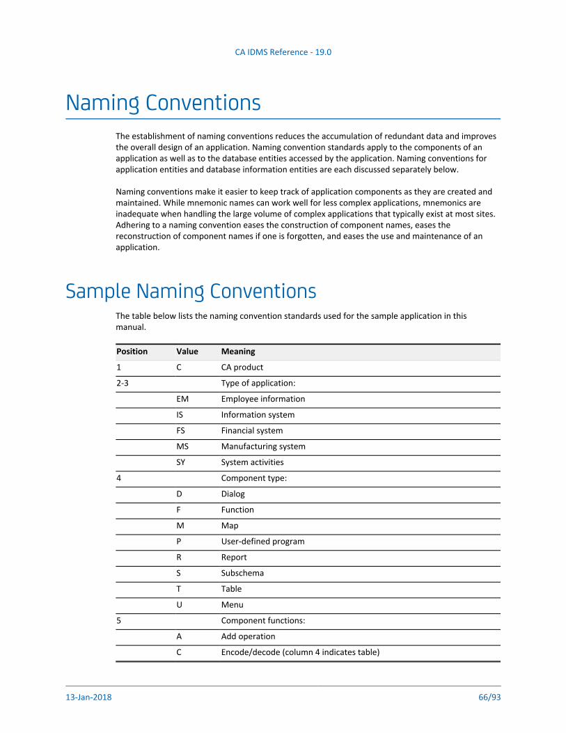
CA IDMS Reference - 19.0
13-Jan-2018 66/93
Naming ConventionsThe establishment of naming conventions reduces the accumulation of redundant data and improves the overall design of an application. Naming convention standards apply to the components of an application as well as to the database entities accessed by the application. Naming conventions for application entities and database information entities are each discussed separately below.
Naming conventions make it easier to keep track of application components as they are created and maintained. While mnemonic names can work well for less complex applications, mnemonics are inadequate when handling the large volume of complex applications that typically exist at most sites. Adhering to a naming convention eases the construction of component names, eases the reconstruction of component names if one is forgotten, and eases the use and maintenance of an application.
Sample Naming ConventionsThe table below lists the naming convention standards used for the sample application in this manual.
Position Value Meaning
1 C CA product
2-3 Type of application:
EM Employee information
IS Information system
FS Financial system
MS Manufacturing system
SY System activities
4 Component type:
D Dialog
F Function
M Map
P User-defined program
R Report
S Subschema
T Table
U Menu
5 Component functions:
A Add operation
C Encode/decode (column 4 indicates table)
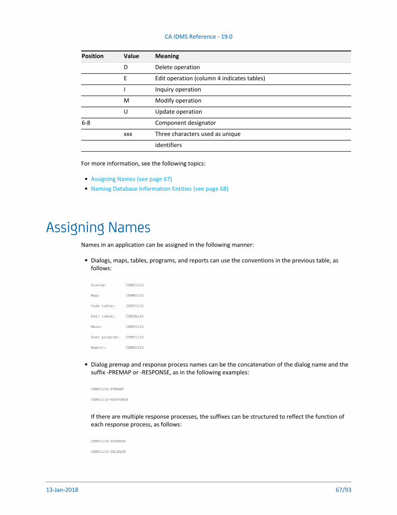
CA IDMS Reference - 19.0
13-Jan-2018 67/93
Position Value Meaning
D Delete operation
E Edit operation (column 4 indicates tables)
I Inquiry operation
M Modify operation
U Update operation
6-8 Component designator
xxx Three characters used as unique
identifiers
For more information, see the following topics:
Assigning Names (see page 67)Naming Database Information Entities (see page 68)
Assigning NamesNames in an application can be assigned in the following manner:
Dialogs, maps, tables, programs, and reports can use the conventions in the previous table, as follows:
Dialog: CEMDILIS
Map: CEMMILIS
Code table: CEMTCLIS
Edit table: CEMTELIS
Menu: CEMUILIS
User program: CEMPILIS
Report: CEMRILIS
Dialog premap and response process names can be the concatenation of the dialog name and the suffix -PREMAP or -RESPONSE, as in the following examples:
CEMDILIS-PREMAP
CEMDILIS-RESPONSE
If there are multiple response processes, the suffixes can be structured to reflect the function of each response process, as follows:
CEMDILIS-ADDRESP
CEMDILIS-DELRESP
Names for subroutines included in the premap and response processes can be made up of a
CA IDMS Reference - 19.0
13-Jan-2018 68/93
Names for subroutines included in the premap and response processes can be made up of a meaningful name of up to six characters with a 2-digit suffix, as follows:
PASSDT05
MESSGE97
DBERR99
The numeric suffixes can be assigned and incremented as the subroutines appear in the dialog. This numbering convention makes it easier to locate a subroutine in the dialog listing. For example, MESSGE97 is located near the end of the listing while PASSDT05 is located near the beginning.
Naming Database Information EntitiesA glossary can be an effective means of establishing naming conventions for database information. The glossary can be stored in the dictionary where it is readily available as a reference tool. Tools such as the glossary also aid in the development of consistent site-specific application coding standards.
Sample Glossary of Naming Tokens (see page 68)Available Naming Conventions (see page 69)
Sample Glossary of Naming TokensThe following example illustrates sample entries from one type of glossary. It shows one way that a glossary can be defined. Each design team must determine the naming conventions that best suit its needs. Note that the word WORD in this example is a user-defined entity defined to the dictionary, as follows:
ADD CLASS NAME IS WORD
CLASS TYPE IS ENTITY.
ADD WORD ABEND ABBREVIATED NEVER
ADD WORD ABSOLUTE ABBREVIATED NEVER
ADD WORD ACCEPT ABBREVIATED NEVER
ADD WORD ACCOUNT ABBREVIATED SOMETIMES ABBR ACCT
ADD WORD ACCRUAL ABBREVIATED NEVER
ADD WORD ACCUMULATE ABBREVIATED SOMETIMES ABBR ACCUM
ADD WORD ACKNOWLEDGE ABBREVIATED SOMETIMES ABBR ACK
ADD WORD ADMINISTRATION ABBREVIATED ALWAYS ABBR ADMIN
ADD WORD ADDRESS ABBREVIATED ALWAYS ABBR ADDR
.
.
.
.
.
.
ADD WORD YIELD ABBREVIATED SOMETIMES ABBR YLD
ADD WORD YTD ACRONYM 'YEAR TO DATE'
ADD WORD YY ABBREVIATED NEVER
CA IDMS Reference - 19.0
13-Jan-2018 69/93
ADD WORD ZERO ABBREVIATED NEVER
ADD WORD ZONE ABBREVIATED NEVER
The sample entries from this glossary show one way that naming conventions can be implemented within an installation. In this glossary, the application designers determined that certain words are always abbreviated and others are never abbreviated. The majority of words are spelled out completely whenever possible. When stored on the dictionary, the glossary is readily available as a reference section for programmers and developers.
Available Naming ConventionsDatabase elements can be established using approved names from the glossary and can be further defined with synonyms. Element names should have a maximum of 25 characters. The following example lists an element and three synonyms:
EMPLOYEE-CODE
DB-REC-EMPLOYEE-CODE
MAP-EMPLOYEE-CODE
WORK-EMPLOYEE-CODE
Database Records can be composed of approved, usable names (for example, EMPLOYEE). Records can be given greater flexibility with the addition of suffixes. The following example lists employee records with identifying suffixes:
EMPLOYEE-0600
EMPLOYEE-2500
EMPLOYEE-6359
SQL: Hyphens are not valid in SQL identifiers referenced in statement syntax. Therefore, SQL entities may not be named using hyphens but may be named using underscores. Hyphens are valid in host variables referenced in SQL statement syntax.For more information, see Programming IDMS SQL (https://docops.ca.com/display/IDMS19
./Programming+IDMS+SQL)
In CA ADS process source, as well as in COBOL, CA Culprit, and map source, the elements can be referenced by the element name plus the suffix, as follows:
EMPLOYEE-CODE-6359
Map work records are composed of the map name followed by the suffix -MAP-RECORD, as in the following example:
CEMMILIS-MAP-RECORD
Elements in the map record utilize the prefix MAP- and the element name, as follows:
MAP-OFFICE-CODE
If the map needs more than one work record, a number is added to the word MAP, as follows:
CA IDMS Reference - 19.0
13-Jan-2018 70/93
If the map needs more than one work record, a number is added to the word MAP, as follows:
CEMMILIS-MAP2-RECORD (the second map record)
MAP2-OFFICE CODE (a record element from the second record)
Dialog work records are composed of the dialog name followed by the suffix -WORK-RECORD as in the following example:
CEMDULIS-WORK-RECORD
Elements in the dialog work record utilize the prefix WORK- and the element name, as follows:
WORK-OFFICE-CODE
If the dialog needs more than one work record, a number is added to the word WORK, as follows:
CEMDILIS-WORK2-RECORD (the second dialog work record)
WORK2-OFFICE CODE (a record element from the second record)
Set names are established by concatenating an abbreviation of the owner record (a seven-character maximum) with that of the member record (a six-character maximum), as follows:
EMPL-SKILL
CA IDMS Reference - 19.0
13-Jan-2018 71/93
Performance ConsiderationsThe performance of the CA ADS runtime system is dependent upon a number of factors, such as the size of the DC/UCF system, the number of applications being run concurrently, and the number of users for a given application. Rather than attempting to give definitive instructions for the improvement of performance, this section discusses the following aspects of the CA ADS runtime system.
Contents
ADSO Statement Parameters (see page 71)PROGRAM Statement Parameters (see page 71)TASK Statement Parameters (see page 72)
The CA ADS runtime system is generated by submitting ADSO, PROGRAM, and TASK statements to the CA IDMS system generation compiler. Optionally, the KEYS statement is used to define site-specific control key functions.
For detailed syntax and examples of system generation statements, refer to Using System Generation .(https://docops.ca.com/display/IDMS/Using+System+Generation)
ADSO Statement ParametersThe ADSO statement includes parameters that define the CA ADS runtime environment, as follows:
The task code (ADS) that initiates the CA ADS runtime system
The mainline dialog that can begin executing immediately
The maximum number of dialog levels that can be established by each application
The disposition of record buffers during a pseudo converse
The size of the primary and secondary record buffers
The AUTOSTATUS facility that handles errors generated by navigational DML, queue record, and scratch record processing
The Status Definition Record that associates status codes returned by non-SQL data processing
PROGRAM Statement ParametersThe PROGRAM statement defines the following CA ADS components as DC/UCF system programs:
The ADSORUN1, ADSORUN2, and ADSOMAIN runtime system programs
CA IDMS Reference - 19.0
13-Jan-2018 72/93
The system maps (the menu map, runtime message map, and maps for each of the application and dialog compiler screens)
The application and dialog compiler programs (ADSA and ADSC)
CA ADS dialogs (an optional parameter if null Program Definition Elements (PDEs) are defined in the SYSTEM statement)
TASK Statement ParametersThe TASK statement defines the following task codes:
ADS and ADS2 to initiate the runtime system
ADSA to initiate the CA ADS Application Compiler
ADSC to initiate the CA ADS Dialog Compiler
ADSR to initiate the runtime system when returning from a linked user program
Parameters affecting performance
Resource management
Each of these considerations is discussed in the following pages:System Generation Parameters (see page 72)Resource Management (see page 75)
System Generation Parameters
Allocating Primary and Secondary Storage PoolsHow Storage is Managed
The runtime system allocates and initializes record buffers for use by executing dialogs. When an application is initiated, CA ADS allocates a Record Buffer Block (RBB) from the DC/UCF system's storage pool to hold the records identified in the dialog definitions and accessed by the dialogs in the application thread. The RBB must be large enough to accommodate the largest of these records.
There is one primary RBB for each application. CA ADS allocates a secondary RBB when the RBB becomes full during execution of the application or does not have enough remaining space to hold a record.
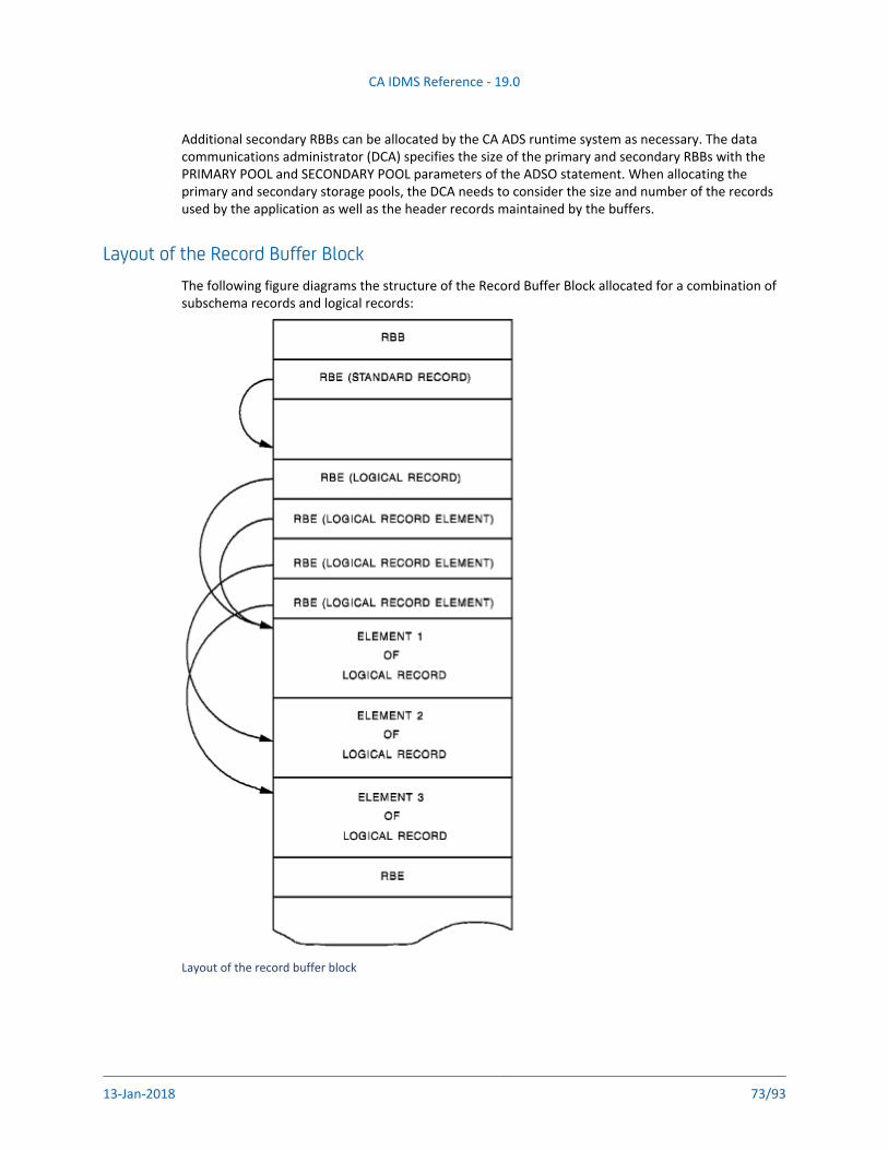
CA IDMS Reference - 19.0
13-Jan-2018 73/93
Additional secondary RBBs can be allocated by the CA ADS runtime system as necessary. The data communications administrator (DCA) specifies the size of the primary and secondary RBBs with the PRIMARY POOL and SECONDARY POOL parameters of the ADSO statement. When allocating the primary and secondary storage pools, the DCA needs to consider the size and number of the records used by the application as well as the header records maintained by the buffers.
Layout of the Record Buffer BlockThe following figure diagrams the structure of the Record Buffer Block allocated for a combination of subschema records and logical records:
Layout of the record buffer block
CA IDMS Reference - 19.0
13-Jan-2018 74/93
Size ConsiderationsEach record buffer contains a 24-byte header to keep track of available space. For each record in the pool, CA ADS maintains a record header (RBE) that requires at least 44 bytes of storage. Each buffer must be large enough to accommodate the largest record used by a dialog in the application.
Setting the Fast Mode ThresholdRecord Buffers
The fast mode threshold is used by the CA ADS runtime system to determine whether record buffers are written to disk or kept in main storage across a pseudo converse. If the total size of all record buffers, in bytes, exceeds the fast mode threshold, the record buffers are written to disk; otherwise, the record buffers are kept in the storage pool.
The size of the threshold is a site-specific determination that is based on the availability of general resources versus the amount of available storage. I/Os for DC/UCF system journaling and CPU cycles for record locking are used when record buffers are written to the scratch/queue areas. Therefore, when buffers exceed the fast mode threshold, the increased use of resources will slow down the transaction response time. On the other hand, if buffers are always under the threshold (that is, if the fast mode threshold is high), more memory is required.
Specifying the Number of Internal and External Run UnitsThe MAXIMUM TASKS and MAXIMUM ERUS parameters specify the maximum number of user tasks and external request units that can be active concurrently. The size of these parameters can affect the amount of time spent by the DC/UCF system in searching the queues for tasks that are waiting to be executed.
The numbers that should be specified are a site-specific determination and are dependent upon factors such as the number of tasks processed each hour in a particular environment. When setting the MAXIMUM TASKS and MAXIMUM ERUS parameters on the SYSTEM statement, the following statistics should be considered:
Increasing the MAXIMUM TASKS or MAXIMUM ERUS parameters by one (1) causes virtual storage requirements to increase as shown below:Resource Size of resource TotalTCE 736 bytes 736 bytesSTACKSIZE 320 words 1,280 bytesDCE 64 bytes 64 bytesECB * 3 8 bytes 24 bytesDPE * 20 16 bytes 320 bytesRCE * 15 24 bytes 360 bytesRLE * 25 12 bytes Total increase per task: 3,084 bytes300 bytes
Note: A value larger than the default (420) should be specified for the STACKSIZE when using CA ADS. If the STACKSIZE is at 420 and two tasks exceed stacksize and go into abend storage at the same time, the system will abort with an abend code of 3995.
CA IDMS Reference - 19.0
13-Jan-2018 75/93
The following DC/UCF system parameters should be increased as specified for every increment of one (1) in the size of MAXIMUM TASKS or MAXIMUM ERUS:Parameter Amount increasedECB LIST 3DPE COUNT 20RCE COUNT 15RLE COUNT 25
Resource ManagementIn designing applications, consideration must be given to the efficient management of system resources. The management of resources such as the database, the storage pool, and the program pool storage affects the performance of online applications because many users may require access to these resources simultaneously.
This article describes the following information:
Application Resource Use (see page 75)Monitoring Resource Consumption (see page 76)Conserving Resources (see page 81)
Application Resource UseThe following figures illustrate the resources used by an application while a task is active and after the task has terminated.
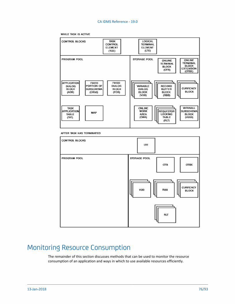
CA IDMS Reference - 19.0
13-Jan-2018 76/93
Monitoring Resource ConsumptionThe remainder of this section discusses methods that can be used to monitor the resource consumption of an application and ways in which to use available resources efficiently.
CA IDMS Reference - 19.0
13-Jan-2018 77/93
ToolsAs with any task running under the DC/UCF system, the major resources to be monitored in an CA ADS environment are as follows:
Task processing support
Variable storage pool
Program pool storage
Database locks
I/Os (disk and terminal data transmission)
CPU cycles
Each of these resources can be monitored with dictionary reports and DC/UCF system master terminal functions, as discussed below.
Task Processing SupportThe next figure shows the resources in use while a task is active and those in use after the task terminates. The following DC/UCF system master terminal functions display the internal resources used to support task processing:
DCMT DISPLAY ACTIVE TASK displays global statistics on active tasks and information on each active task thread.
DCMT DISPLAY STATISTICS SYSTEM displays information about the system including the peak task control element (TCE) stack; and the maximum number of resource link elements (RLEs), resource control elements (RCEs), and deadlock prevention elements (DPEs) used by the tasks.
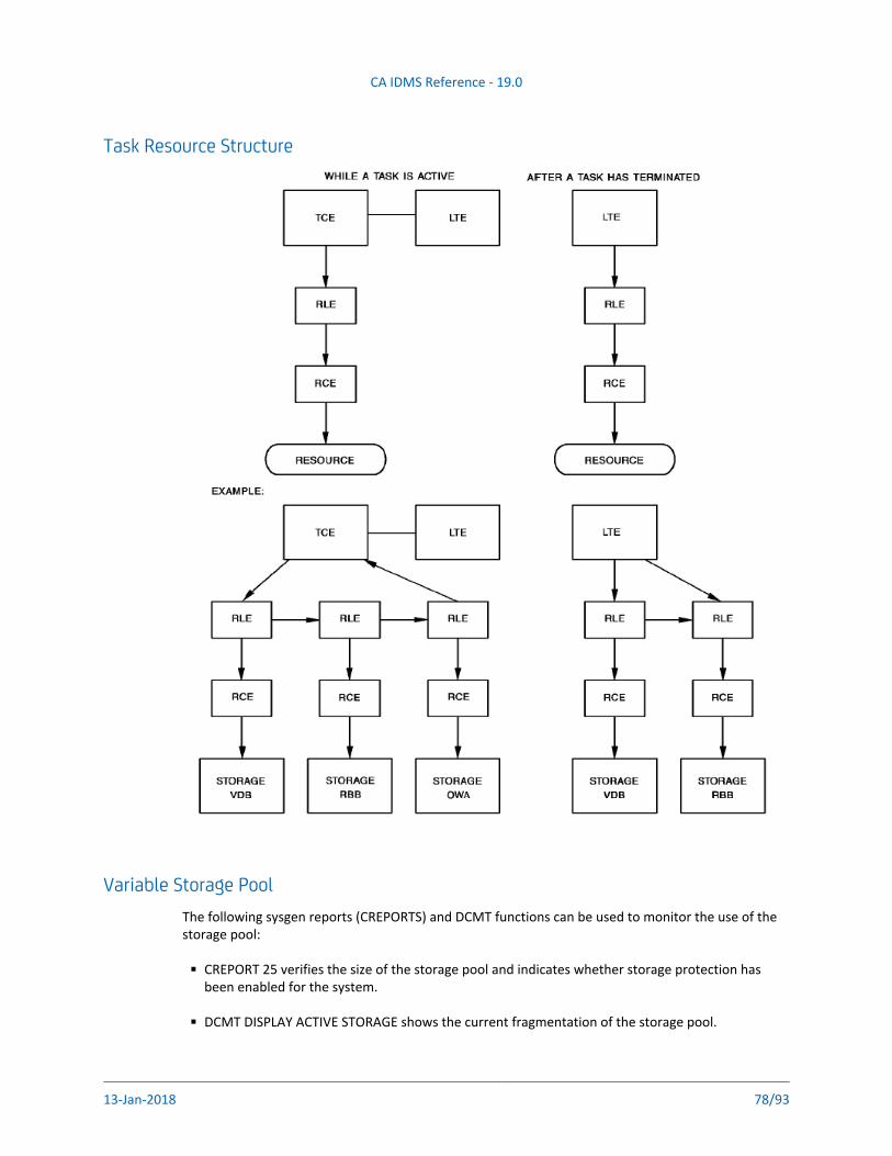
CA IDMS Reference - 19.0
13-Jan-2018 78/93
Task Resource Structure
Variable Storage PoolThe following sysgen reports (CREPORTS) and DCMT functions can be used to monitor the use of the storage pool:
CREPORT 25 verifies the size of the storage pool and indicates whether storage protection has been enabled for the system.
DCMT DISPLAY ACTIVE STORAGE shows the current fragmentation of the storage pool.
DCMT DISPLAY LTERM indicates which terminals are active and own resources.
CA IDMS Reference - 19.0
13-Jan-2018 79/93
DCMT DISPLAY LTERM indicates which terminals are active and own resources.
DCMT DISPLAY LTERM RESOURCES displays the specific resources (and the logical-terminal-idaddresses of those resources) owned by the named terminal.
DCMT DISPLAY MEMORY can be used to display an actual resource as it appears in memory.
CREPORT 40 supplies the current parameters specified in the ADSO statement, as it this example:
REPORT NO. 40 CA-IDMS/DC ADS REPORT
LISTING OF CA-ADS PARAMETERS
OBJECT REPORT
SYSTEM PRIMARY SECONDARY MAXIMUM FAST MODE PRIMARY
VERSION AUTODIALOG TASK CODE TASK CODE LINKS MENU IS THRESHOLD POOL
90 ADS ADS2 10 USER 50000 40
99 ADS ADS2 10 USER KEEP OFF 40
Information from the above displays and reports can be used to calculate the number of users the system can currently support, assuming various storage pool sizes.
The manual describes CREPORTS; the CA IDMS Administrating section CA IDMS System Reference manual details the master terminal functions available to monitor system resources.section
Program Pool StorageThe following DCMT commands can be used to provide information on the program pool:
DCMT DISPLAY ACTIVE PROGRAMS displays the following:
Statistics on program pool usage, including the total number of pages and total number of bytes in the pool; the number of loads to the program pool; the number of pages loaded; and the number of load conflicts
Information on currently active programs including the program name, type, and version number; count of users currently using the programs; size of the program in K bytes; the number of times the program was called; and the number of times the program was loaded into the program pool
The program pool page allocation map that shows which pages are not in use; which pages are in use by one program; and which pages are in used by more than one program
DCMT DISPLAY ACTIVE REENTRANT PROGRAMS displays the above information for the reentrant program pool and the active reentrant programs. If no reentrant pool is defined, the standard program pool is shown.
CA IDMS Reference - 19.0
13-Jan-2018 80/93
1.
2.
3.
4.
5.
Database LocksThe DCMT DISPLAY RUN UNIT and OPER WATCH DB RUN UNITS commands can be used to show the number of database locks being requested for a particular run unit. The number of database locks maintained by an CA IDMS system has considerable impact on CPU usage. These locks are specified at sysgen time by the RULOCKS and SYSLOCKS parameters of the SYSTEM statement.
For further information on database locks, refer to CA IDMS Database Design Guide
For further information on factors to consider when preparing the SYSTEM statement, refer to CA .IDMS System Reference section
Disk I/OThe following reports can be used for monitoring disk I/O:
JREPORT 004 shows the average number of I/Os to disk for a given program.
DCMT DISPLAY RUN UNITS or OPER W DB RU shows if any run units are waiting for a journal buffer (as indicated by a run unit status value of IUH). IUHs occur most frequently when the fast mode threshold is set too low.
For information on JREPORTS (journal reports), refer to .CA IDMS Reporting section
Monitor Terminal I/OUse the following procedure to monitor terminal I/O.
To monitor terminal I/Os
Run the mapping utility (RHDCMPUT) for a report on a specific map. This report will display a picture of the map and the attributes currently assigned to the map. The report will also indicate whether BACKSCAN is enabled for any mapping fields. If BACKSCAN is in effect and the NEWPAGE option on the ADSO statement has been selected, extraneous data from the previous mapout may be left on the screen when a map is redisplayed. It is advantageous to have NEWPAGE in effect, however, because this option increases runtime efficiency by reducing the number of data fields that need to be transmitted to the terminal.
Use DCMT VARY PTERM TRACE ALLIO to cause the data stream being physical-terminal-idtransmitted to the terminal to be written to the log as well.
Use SHOWMAP with DCUF USERTRACE to cause the data stream of a particular map-namemap to be traced.
Use DCMT VARY PTERM TRACE ALLIO OFF to turn off the trace, physical-terminal-idsuppressing any further transmission of data streams to the log.
Run the PRINT LOG utility to show the actual trace.
Transmission times can be calculated by analyzing the length of the data stream.
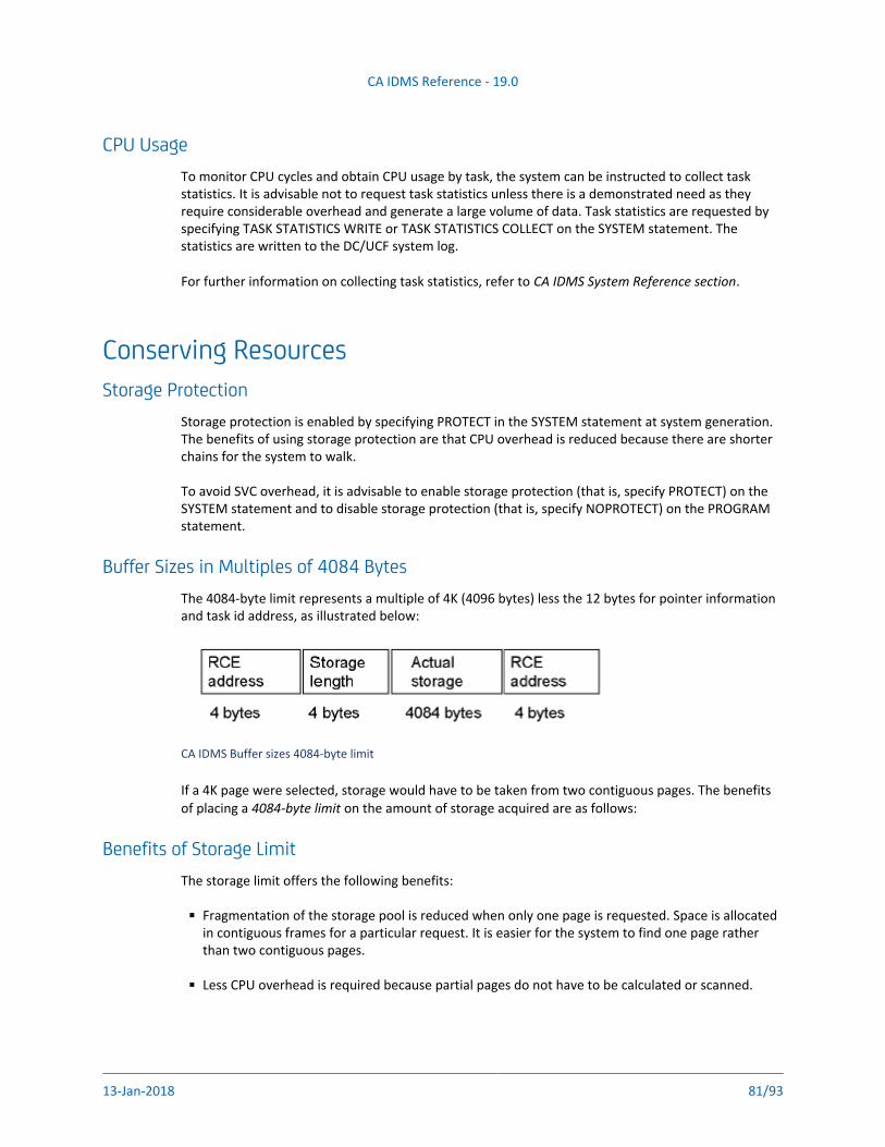
CA IDMS Reference - 19.0
13-Jan-2018 81/93
CPU UsageTo monitor CPU cycles and obtain CPU usage by task, the system can be instructed to collect task statistics. It is advisable not to request task statistics unless there is a demonstrated need as they require considerable overhead and generate a large volume of data. Task statistics are requested by specifying TASK STATISTICS WRITE or TASK STATISTICS COLLECT on the SYSTEM statement. The statistics are written to the DC/UCF system log.
For further information on collecting task statistics, refer to .CA IDMS System Reference section
Conserving ResourcesStorage Protection
Storage protection is enabled by specifying PROTECT in the SYSTEM statement at system generation. The benefits of using storage protection are that CPU overhead is reduced because there are shorter chains for the system to walk.
To avoid SVC overhead, it is advisable to enable storage protection (that is, specify PROTECT) on the SYSTEM statement and to disable storage protection (that is, specify NOPROTECT) on the PROGRAM statement.
Buffer Sizes in Multiples of 4084 BytesThe 4084-byte limit represents a multiple of 4K (4096 bytes) less the 12 bytes for pointer information and task id address, as illustrated below:
CA IDMS Buffer sizes 4084-byte limit
If a 4K page were selected, storage would have to be taken from two contiguous pages. The benefits of placing a on the amount of storage acquired are as follows:4084-byte limit
Benefits of Storage LimitThe storage limit offers the following benefits:
Fragmentation of the storage pool is reduced when only one page is requested. Space is allocated in contiguous frames for a particular request. It is easier for the system to find one page rather than two contiguous pages.
Less CPU overhead is required because partial pages do not have to be calculated or scanned.
CA IDMS Reference - 19.0
13-Jan-2018 82/93
Size of SubschemasSubschemas for navigational DML access should be specified to the requirements of the application. The size of the currency block is directly related to the storage requirements of the variable subschema storage block (VB50) used at run time; the runtime system maintains currency tables for every record, set, and area in a subschema, regardless of whether they are accessed by the dialog. Therefore, it is worthwhile to make subschemas as streamlined as possible.
Number of Dialog LevelsThe MAXIMUM LINKS parameter of the ADSO sysgen statement specifies the maximum number of dialog levels that can be established by each respective CA ADS application; keep this parameter low. A well designed application has as few levels as possible. The number of levels should be limited because, for each level established in the application, kept storage is acquired for the Variable Dialog Block (VDB) and the currency block. Storage established at a particular level is not released until control is passed upward.
To limit the number of levels established, use the TRANSFER command whenever possible; build the application horizontally (that is, pass control laterally) rather than vertically.
Size of the ApplicationThe size of dialog premap and response processes, the number of data fields included in a map, and the size of records affect the performance of the CA ADS runtime system. The actual number of I/Os required to load a complete program is dependent upon the size of a page in the DDLDCLOD area, the amount of overflow that will be encountered to load that record, and the size of the actual program being loaded. Therefore, the following benefits are realized by minimizing the size of programs:
A reduction in the work required to load a small program as compared to a large program
A reduction in time spent loading a particular program in the program pool or reentrant pool
A reduction in time spent waiting for space in the program pool or reentrant pool
Under the DC/UCF system, the term program includes dialogs, edit and code tables, maps, subschemas, and online and batch programs.
Making Frequently Called Programs ResidentA frequently called program (such as ADSOMAIN) is virtually a resident in the program pool or the reentrant pool. The program should be made resident because the operating system can page more rapidly than the DC/UCF system can read in a page from the DDLDCLOD area. By making the program resident, the operating system, rather than the DC/UCF system, will be requested to bring the page in core. Additionally, the program and resident pool will be less fragmented when a frequently used program is made resident. A program can be specified as resident on the PROGRAM statement at system generation.
CA IDMS Reference - 19.0
13-Jan-2018 83/93
Freeing the Resources of an Inactive TerminalThe resource timeout facility can be activated on the SYSTEM statement at system generation, specifying the amount of time a terminal is permitted to be inactive (that is, have no task executing) before all resources owned by the terminal are deleted and control is returned to the system. Because longterm storage resources are associated with a terminal even though a program is not active, freeing those resources will free space for other users of the system. This is particularly important in navigational DML if longterm locks are being implemented.
CA IDMS Reference - 19.0
13-Jan-2018 84/93
Application ConceptsThis section provides an overview of application terms and concepts within the CA ADS environment. The following topics are discussed:
Application components -- The two basic parts of an CA ADS application
Dialog features -- The components and procedures that make up a dialog
Control Commands -- The commands that can be used to pass control within an application
Flow of Control -- How the runtime system determines the way in which an application is executed.
The Structure of an CA ADS ApplicationAn application is composed of functions and responses. Functions define the activities that can be performed in an application; responses associate the functions with one another and direct the flow of processing. A response can be associated with a control key and/or a code entered by the user.
For more information, see the following topics:Application Components (see page 84)Dialog Features (see page 88)Control Commands (see page 90)The Flow of Control (see page 91)
Application ComponentsAn application is composed of and . The following figure illustrates the functions responsesrelationship between functions and responses. Each of these components is described below:
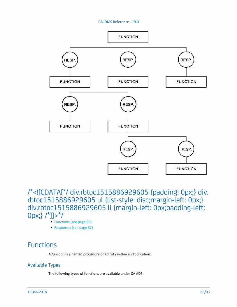
CA IDMS Reference - 19.0
13-Jan-2018 85/93
/*<![CDATA[*/ div.rbtoc1515886929605 {padding: 0px;} div.rbtoc1515886929605 ul {list-style: disc;margin-left: 0px;} div.rbtoc1515886929605 li {margin-left: 0px;padding-left: 0px;} /*]]>*/
Functions (see page 85)Responses (see page 87)
FunctionsA is a named procedure or activity within an application.function
Available TypesThe following types of functions are available under CA ADS:
Menu Functions are used to direct a user through an application. The menus contain a list of valid
CA IDMS Reference - 19.0
13-Jan-2018 86/93
Menu Functions are used to direct a user through an application. The menus contain a list of valid responses for the terminal user to use when processing in application. System-defined menus are built automatically by the runtime system.
Dialog Functions are used for data processing, such as database access. A dialog function can have any number of valid responses defined for it during application generation. A response can activate another dialog function or can activate a dialog not defined as a function.
Menu/Dialog Functions are dialogs that display a user-defined menu. When a menu is associated with a dialog, its map is displayed when the executing dialog issues a DISPLAY process command. Menu/dialogs must be used if the menu map is user-defined.
For further information on the options available when designing menus for an application, refer to Chapter 4, Designing Maps.
System Functions are predefined. Available to all applications, they perform the same action in all applications to which they are assigned. The use of system functions adds flexibility to an application, eliminating the need to write code for a given activity.
Available System FunctionsThe following system functions are available:
POPReturns processing control to the previous menu in the application thread.
POPTOPReturns processing control to the first menu in the application thread.
TOPreturns processing control to the highest function in the current application thread.
RETURNReturns processing control to the next higher function in the current application thread.
Note: If a RETURN command is coded into a response process, it is considered a process command, a system function. As a process command, RETURN performs as it would in notan the DC/UCF system's environment.
HELPDisplays a HELP screen at run time. This screen lists all valid responses for the current function.
QUITTerminates processing of the current application. If previously signed on to the application, the user is automatically signed off.
SIGNON/SIGNOFFAllows a user to signon or signoff. This is an CA IDMS/DC signon/signoff function executed from within the application.
CA IDMS Reference - 19.0
13-Jan-2018 87/93
FORWARD/BACKWARDAllows a user to page forward or backward on menu maps.
System functions can be subdivided as follows:
QUIT, POPTOP, POP, TOP, and RETURN are generally executed when an EXECUTE NEXT FUNCTION command is encountered.
SIGNON, SIGNOFF, and HELP are always executed as soon as they are encountered by the runtime system.
FORWARD and BACKWARD (menu functions only) are executed as soon as they are encountered. If associated with a nonmenu dialog function, the FORWARD and BACKWARD functions are moved into the ADSO-APPLICATION-GLOBAL-RECORD prior to executing the dialog's response process.
User Program Functions are written in a process language other than CA ADS. When a user program function is activated, the CA ADS runtime system relinquishes control to the user program. CA ADS does not define valid responses for a user program; any responses made by the user must be processed by the executing user program. The runtime system maintains all buffers for the application at the level at which control was relinquished, anticipating return of the processing control.
Internal Functions are associated with the current dialog function. An internal function is assumed to be a response defined for the dialog response process.
The developer might define a response that initiates an internal function as a method of documenting the response process and/or as a method of providing the dialog response process as a valid response choice at run time. Additionally, a security class can be assigned to this type of response, thereby enabling security protection for a dialog's response process.
ResponsesA is a named entity that establishes a relationship between two functions. A response can response be a control key or a response value entered in the response field by the user.
Note: It is important to distinguish between a and a . A response response process responseis the action taken by the user when pressing a key or entering a response value. A response is defined by the CA ADS Application Compiler; it can initiate an application function or the dialog's response process.
A is the dialog component that receives data from the terminal user, processes it response processaccordingly, and passes control to the next activity. A response process is stored as a MODULE-067 record (with the attribute LANGUAGE IS PROCESS) and is associated with a dialog by using the CA ADS Dialog Compiler in an ADSC session.
CA IDMS Reference - 19.0
13-Jan-2018 88/93
Processing control is directed by the valid responses of a function. When a valid response to the current function is selected by the user, a new function (or a reiteration of the current function) is executed.
Dialog FeaturesA dialog enables interaction between the user and the application and can be defined in terms of its components and how it accomplishes its job. The components and procedures of a dialog are discussed in the following sections.
The following topics are discussed in this section:
Dialog Components (see page 88)Dialog Procedures (see page 89)
Dialog ComponentsEach dialog consists of the following components:
MapProvides a means of communication between the application and the user. Map definitions in the dictionary maintain a formatted screen layout of literal and variable map fields (that is, data fields). Map data fields are associated with areas in program variable storage and are contained in map records. There can be only one map for each dialog. The application developer defines the map online with the online mapping facility; the resulting map load module is stored in the load area of the data dictionary.
ProcessesPerforms data retrieval and processing. Processes are instructions written in CA ADS process code. Each process consists of one or more commands that specify the type of processing to be performed (for example, database accessing, conditional testing, inter- and intra-dialog communication). A dialog is associated with two types of processes: premap and response. Both types are optional. A maximum of one premap process can be associated with a dialog; there is no limit to the number of response processes.The application developer defines the processes by using the batch or online capabilities of IDD. The batch DDDL compiler stores the source statements as modules in the dictionary.
SubschemaProvides the dialog with a view of the database. Each dialog can be associated with a maximum of one subschema. Subschemas are defined by the database administrator and stored in the dictionary by the subschema compiler. Subschemas are associated with dialogs when a dialog is compiled by ADSC.
RecordsSupplies data to the dialog for processing. A dialog obtains data from a combination of records, as follows:
CA IDMS Reference - 19.0
13-Jan-2018 89/93
Subschema recordsIdentifies the database and logical records that comprise the subschema.
Map records Identifies subschema or work records.
Dialog work records Identifies dictionary records used as working storage by a dialog.These records contain the data elements that are needed by the application. Data elements and records are created with the use of IDD DDDL and are stored in the dictionary. They can have associated values, edit criteria, external and internal pictures, and code tables that are all recognized by the maps and dialogs of an application. For a more detailed discussion on creating the records used in an application, see Design Methodology. (see page 17)
Dialog ProceduresWhen the CA ADS runtime system executes a dialog, one or all of the following procedures can take place:
Premap processingPerforms optional processing prior to displaying a map to the user. For example, the dialog can retrieve a record that contains the data to be displayed by the map. The dialog premap procedure is not automatic.
MapoutDisplays a formatted screen (map) for use by the user. The user uses the map to supply data and to specify how this data is to be processed. For example, a dialog can display data from a customer record; the user then updates the record and requests that it be modified in the database. The mapout procedure is automatic when there is no premap processing; otherwise a mapout occurs when the DISPLAY command is issued.
MapinReceives data and the requested response from the user. For example, if the user requests that the customer record be modified, the values that the user keys into the map data fields are then moved into variable storage. The dialog mapin procedure is performed automatically when the user presses a control key.
Response process selectionSelects a response process based on the response entered by the user. The runtime system performs this procedure automatically.
Response processingProcesses data as directed by the terminal user's response (for example, modifies the customer record) and specifies the next activity to be executed. Response processing is not performed automatically.
CA IDMS Reference - 19.0
13-Jan-2018 90/93
Control CommandsThe application developer can use specific CA ADS commands to perform the following operations:
Pass control from one dialog to another dialog or to a user program
Display a map
Terminate an existing dialog or application
Exit the CA ADS environment
Direct processing to specified places within a dialog
Reinitialize the record buffers associated with a dialog
Establish the status and level of a dialog within the application structure
Implicitly govern the available data and database currencies that are maintained for a dialog
Most of the control commands are available to all applications. When designing dialogs that become part of an application that is defined by using the CA ADS Application Compiler, the developer can also use the EXECUTE NEXT FUNCTION command.
The CA ADS control commands are as follows:
DISPLAYRequests display of the map of the dialog or reexecution of the premap process
INVOKESpecifies the next lower-level dialog to be executed in the application thread
LEAVETerminates the current application, optionally initiating another application, or terminating the CA ADS session
LINKSpecifies the next lower-level dialog to be executed in the application thread, implicitly establishing a nested application structure, or links to a user program that executes outside the CA ADS environment
RETURNTerminates the currently executing dialog, returns control to a higher-level dialog, and, optionally, initializes the record buffers of that dialog
TRANSFERTerminates the currently executing dialog and passes control to a dialog at the same level (which can be the same dialog)
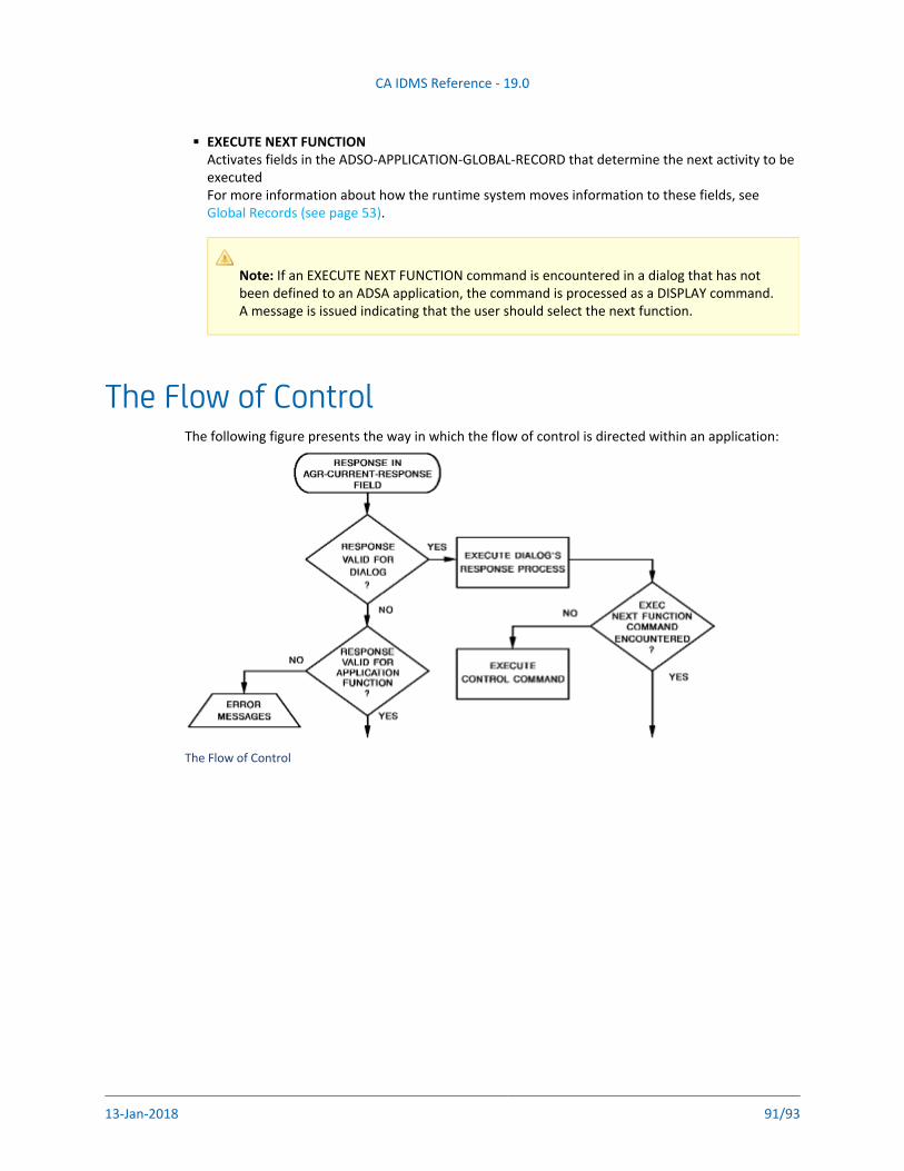
CA IDMS Reference - 19.0
13-Jan-2018 91/93
EXECUTE NEXT FUNCTIONActivates fields in the ADSO-APPLICATION-GLOBAL-RECORD that determine the next activity to be executedFor more information about how the runtime system moves information to these fields, see
.Global Records (see page 53)
Note: If an EXECUTE NEXT FUNCTION command is encountered in a dialog that has not been defined to an ADSA application, the command is processed as a DISPLAY command. A message is issued indicating that the user should select the next function.
The Flow of ControlThe following figure presents the way in which the flow of control is directed within an application:
The Flow of Control
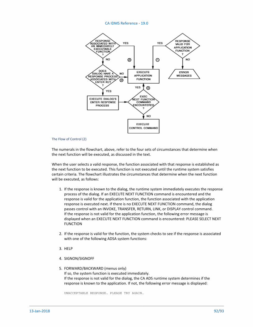
CA IDMS Reference - 19.0
13-Jan-2018 92/93
1.
2.
3.
4.
5.
The Flow of Control (2)
The numerals in the flowchart, above, refer to the four sets of circumstances that determine when the next function will be executed, as discussed in the text.
When the user selects a valid response, the function associated with that response is established as the next function to be executed. This function is not executed until the runtime system satisfies certain criteria. The flowchart illustrates the circumstances that determine when the next function will be executed, as follows:
If the response is known to the dialog, the runtime system immediately executes the response process of the dialog. If an EXECUTE NEXT FUNCTION command is encountered and the response is valid for the application function, the function associated with the application response is executed next. If there is no EXECUTE NEXT FUNCTION command, the dialog passes control with an INVOKE, TRANSFER, RETURN, LINK, or DISPLAY control command.If the response is not valid for the application function, the following error message is displayed when an EXECUTE NEXT FUNCTION command is encountered: PLEASE SELECT NEXT FUNCTION
If the response is valid for the function, the system checks to see if the response is associated with one of the following ADSA system functions:
HELP
SIGNON/SIGNOFF
FORWARD/BACKWARD (menus only)If so, the system function is executed immediately.If the response is not valid for the dialog, the CA ADS runtime system determines if the response is known to the application. If not, the following error message is displayed:
UNACCEPTABLE RESPONSE. PLEASE TRY AGAIN.
CA IDMS Reference - 19.0
13-Jan-2018 93/93
6.
7.
If the response is valid for the application function, but not known to the dialog, and if the response is not an immediately executable ADSA system function, the runtime system checks to see if there is a response process associated with the ENTER key. If there is no such associated response process, the application function is executed immediately.
If the status of the response is the same as in situation #3 (that is, valid for the application, not known to the dialog, and not an immediately executable function) and a response process
associated with the ENTER key, the ENTER response process is executed first and the isapplication function is executed when an EXECUTE NEXT FUNCTION is encountered. If there is no EXECUTE NEXT FUNCTION command, the dialog passes control with an INVOKE, LINK, TRANSFER, RETURN, or DISPLAY command, as in the first example.


![[MS-ADSO]: Active Directory System Overview...[MS-ADSO]: Active Directory System Overview Intellectual Property Rights Notice for Open Specifications Documentation Technical Documentation](https://img.pdfslide.us/doc/110x75/60baf1764e94796549538092/ms-adso-active-directory-system-overview-ms-adso-active-directory-system.jpg)