Embed Size (px)
Citation preview

ca_C1-C61.qxd:Layout 1 2/10/11 9:32 AM Page 1
C
D Su
b
C-11www.ittcannon.com
Dimensions shown in inches (mm)Specifications and dimensions subject to change
Engaging Face
10°
E
C
B
A
D
Ø 3,05 (.120)
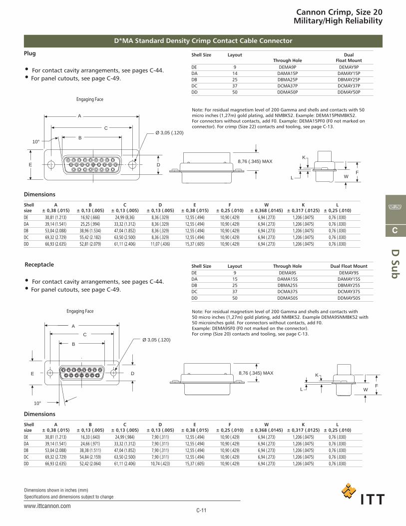
Cannon Crimp, Size 20Military/High Reliability
D*MA Standard Density Crimp Contact Cable Connector
Dimensions
Receptacle
• For contact cavity arrangements, see pages C-44. • For panel cutouts, see page C-49.
Shell Size Layout Through Hole Dual Float MountDE 9 DEMA9S DEMAY9SDA 15 DAMA15S DAMAY15SDB 25 DBMA25S DBMAY25SDC 37 DCMA37S DCMAY37SDD 50 DDMA50S DDMAY50S
Note: For residual magnetism level of 200 Gamma and shells and contacts with 50 micro inches (1,27m) gold plating, add NMBK52. Example DEMA9SNMBK52 with50 microinches gold. For connectors without contacts, add F0. Example: DEMA9S F0 (F0 not marked on the connector). For crimp (Size 20) contacts and tooling, see page C-13.
Shell A B C D E F W K Lsize ± 0,38 (.015) ± 0,13 (.005) ± 0,13 (.005) ± 0,13 (.005) ± 0,38 (.015) ± 0,25 (.010) ± 0,368 (.0145) ± 0,317 (.0125) ± 0,25 (.010)DE 30,81 (1.213) 16,33 (.643) 24,99 (.984) 7,90 (.311) 12,55 (.494) 10,90 (.429) 6,94 (.273) 1,206 (.0475) 0,76 (.030)DA 39,14 (1.541) 24,66 (.971) 33,32 (1.312) 7,90 (.311) 12,55 (.494) 10,90 (.429) 6,94 (.273) 1,206 (.0475) 0,76 (.030)DB 53,04 (2.088) 38,38 (1.511) 47,04 (1.852) 7,90 (.311) 12,55 (.494) 10,90 (.429) 6,94 (.273) 1,206 (.0475) 0,76 (.030)DC 69,32 (2.729) 54,84 (2.159) 63,50 (2.500) 7,90 (.311) 12,55 (.494) 10,90 (.429) 6,94 (.273) 1,206 (.0475) 0,76 (.030)DD 66,93 (2.635) 52,42 (2.064) 61,11 (2.406) 10,74 (.423) 15,37 (.605) 10,90 (.429) 6,94 (.273) 1,206 (.0475) 0,76 (.030)
8,76 (.345) MAX
LF
W
K
Plug
• For contact cavity arrangements, see pages C-44. • For panel cutouts, see page C-49.
Shell Size Layout DualThrough Hole Float Mount
DE 9 DEMA9P DEMAY9PDA 14 DAMA15P DAMAY15PDB 25 DBMA25P DBMAY25PDC 37 DCMA37P DCMAY37PDD 50 DDMA50P DDMAY50P
Note: For residual magnetism level of 200 Gamma and shells and contacts with 50micro inches (1,27m) gold plating, add NMBK52. Example: DEMA15PNMBK52.For con nectors without contacts, add F0. Example: DEMA15PF0 (F0 not marked onconnector). For crimp (Size 22) contacts and tooling, see page C-13.
Dimensions
Shell A B C D E F W K Lsize ± 0,38 (.015) ± 0,13 (.005) ± 0,13 (.005) ± 0,13 (.005) ± 0,38 (.015) ± 0,25 (.010) ± 0,368 (.0145) ± 0,317 (.0125) ± 0,25 (.010)DE 30,81 (1.213) 16,92 (.666) 24,99 (8,36) 8,36 (.329) 12,55 (.494) 10,90 (.429) 6,94 (.273) 1,206 (.0475) 0,76 (.030)DA 39,14 (1.541) 25,25 (.994) 33,32 (1.312) 8,36 (.329) 12,55 (.494) 10,90 (.429) 6,94 (.273) 1,206 (.0475) 0,76 (.030)DB 53,04 (2.088) 38,96 (1.534) 47,04 (1.852) 8,36 (.329) 12,55 (.494) 10,90 (.429) 6,94 (.273) 1,206 (.0475) 0,76 (.030)DC 69,32 (2.729) 55,42 (2.182) 63,50 (2.500) 8,36 (.329) 12,55 (.494) 10,90 (.429) 6,94 (.273) 1,206 (.0475) 0,76 (.030)DD 66,93 (2.635) 52,81 (2.079) 61,11 (2.406) 11,07 (.436) 15,37 (.605) 10,90 (.429) 6,94 (.273) 1,206 (.0475) 0,76 (.030)
Engaging Face
A
C
B10°
E D
Ø 3,05 (.120)
8,76 (.345) MAX
L
K
FW
ca_C1-C61.qxd:Layout 1 2/10/11 9:32 AM Page 11
C
D S
ub
C-12www.ittcannon.com
Dimensions shown in inches (mm)Specifications and dimensions subject to change
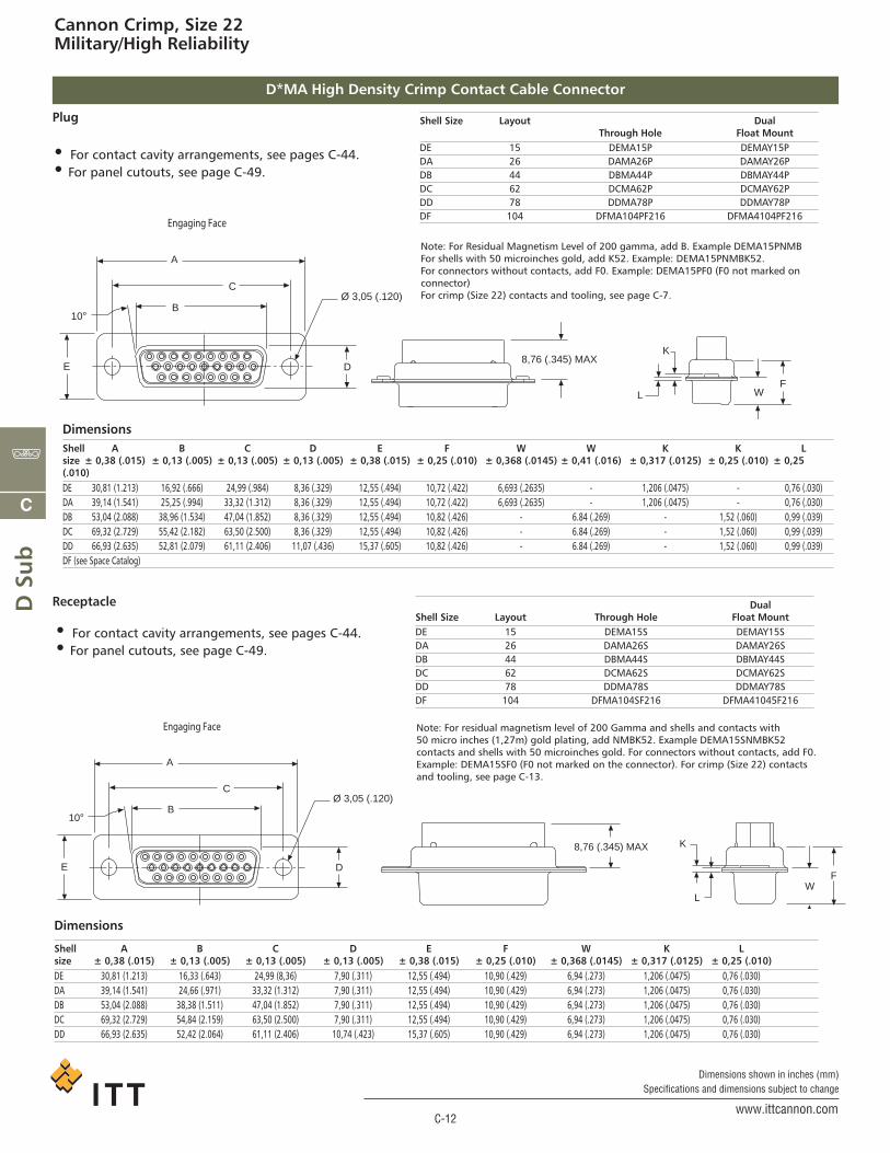
Cannon Crimp, Size 22Military/High Reliability
D*MA High Density Crimp Contact Cable Connector
Note: For Residual Magnetism Level of 200 gamma, add B. Example DEMA15PNMBFor shells with 50 microinches gold, add K52. Example: DEMA15PNMBK52.For connectors without contacts, add F0. Example: DEMA15PF0 (F0 not marked onconnector)For crimp (Size 22) contacts and tooling, see page C-7.
Dimensions
Shell A B C D E F W K Lsize ± 0,38 (.015) ± 0,13 (.005) ± 0,13 (.005) ± 0,13 (.005) ± 0,38 (.015) ± 0,25 (.010) ± 0,368 (.0145) ± 0,317 (.0125) ± 0,25 (.010)DE 30,81 (1.213) 16,33 (.643) 24,99 (8,36) 7,90 (.311) 12,55 (.494) 10,90 (.429) 6,94 (.273) 1,206 (.0475) 0,76 (.030)DA 39,14 (1.541) 24,66 (.971) 33,32 (1.312) 7,90 (.311) 12,55 (.494) 10,90 (.429) 6,94 (.273) 1,206 (.0475) 0,76 (.030)DB 53,04 (2.088) 38,38 (1.511) 47,04 (1.852) 7,90 (.311) 12,55 (.494) 10,90 (.429) 6,94 (.273) 1,206 (.0475) 0,76 (.030)DC 69,32 (2.729) 54,84 (2.159) 63,50 (2.500) 7,90 (.311) 12,55 (.494) 10,90 (.429) 6,94 (.273) 1,206 (.0475) 0,76 (.030)DD 66,93 (2.635) 52,42 (2.064) 61,11 (2.406) 10,74 (.423) 15,37 (.605) 10,90 (.429) 6,94 (.273) 1,206 (.0475) 0,76 (.030)
Engaging Face
A
C
B10°
E D
Ø 3,05 (.120)
8,76 (.345) MAX
L
K
FW
Receptacle
• For contact cavity arrangements, see pages C-44. • For panel cutouts, see page C-49.
Note: For residual magnetism level of 200 Gamma and shells and contacts with 50 micro inches (1,27m) gold plating, add NMBK52. Example DEMA15SNMBK52 contacts and shells with 50 microinches gold. For connectors without contacts, add F0. Example: DEMA15SF0 (F0 not marked on the connector). For crimp (Size 22) contactsand tooling, see page C-13.
DualShell Size Layout Through Hole Float MountDE 15 DEMA15S DEMAY15SDA 26 DAMA26S DAMAY26SDB 44 DBMA44S DBMAY44SDC 62 DCMA62S DCMAY62SDD 78 DDMA78S DDMAY78SDF 104 DFMA104SF216 DFMA41045F216
DimensionsShell A B C D E F W W K K Lsize ± 0,38 (.015) ± 0,13 (.005) ± 0,13 (.005) ± 0,13 (.005) ± 0,38 (.015) ± 0,25 (.010) ± 0,368 (.0145) ± 0,41 (.016) ± 0,317 (.0125) ± 0,25 (.010) ± 0,25(.010)DE 30,81 (1.213) 16,92 (.666) 24,99 (.984) 8,36 (.329) 12,55 (.494) 10,72 (.422) 6,693 (.2635) - 1,206 (.0475) - 0,76 (.030)DA 39,14 (1.541) 25,25 (.994) 33,32 (1.312) 8,36 (.329) 12,55 (.494) 10,72 (.422) 6,693 (.2635) - 1,206 (.0475) - 0,76 (.030)DB 53,04 (2.088) 38,96 (1.534) 47,04 (1.852) 8,36 (.329) 12,55 (.494) 10,82 (.426) - 6.84 (.269) - 1,52 (.060) 0,99 (.039)DC 69,32 (2.729) 55,42 (2.182) 63,50 (2.500) 8,36 (.329) 12,55 (.494) 10,82 (.426) - 6.84 (.269) - 1,52 (.060) 0,99 (.039)DD 66,93 (2.635) 52,81 (2.079) 61,11 (2.406) 11,07 (.436) 15,37 (.605) 10,82 (.426) - 6.84 (.269) - 1,52 (.060) 0,99 (.039)DF (see Space Catalog)
Engaging Face
A
C
B10°
E D
Ø 3,05 (.120)
8,76 (.345) MAX
FW
L
K
Plug
• For contact cavity arrangements, see pages C-44. • For panel cutouts, see page C-49.
Shell Size Layout DualThrough Hole Float Mount
DE 15 DEMA15P DEMAY15PDA 26 DAMA26P DAMAY26PDB 44 DBMA44P DBMAY44PDC 62 DCMA62P DCMAY62PDD 78 DDMA78P DDMAY78PDF 104 DFMA104PF216 DFMA4104PF216
ca_C1-C61.qxd:Layout 1 2/10/11 9:32 AM Page 12
C
D Su
b
C-13www.ittcannon.com
Dimensions shown in inches (mm)Specifications and dimensions subject to change
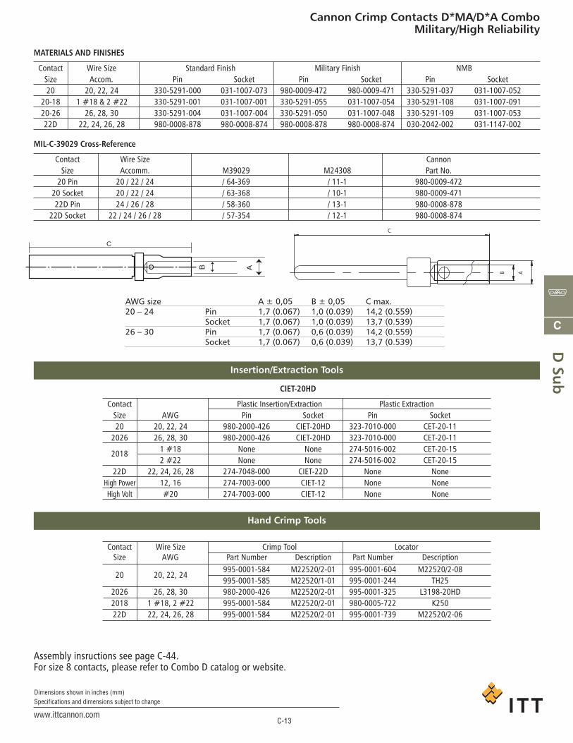
Cannon Crimp Contacts D*MA/D*A ComboMilitary/High Reliability
MATERIALS AND FINISHES
Contact Wire Size Standard Finish Military Finish NMBSize Accom. Pin Socket Pin Socket Pin Socket20 20, 22, 24 330-5291-000 031-1007-073 980-0009-472 980-0009-471 330-5291-037 031-1007-052
20-18 1 #18 & 2 #22 330-5291-001 031-1007-001 330-5291-055 031-1007-054 330-5291-108 031-1007-09120-26 26, 28, 30 330-5291-004 031-1007-004 330-5291-050 031-1007-048 330-5291-109 031-1007-05322D 22, 24, 26, 28 980-0008-878 980-0008-874 980-0008-878 980-0008-874 030-2042-002 031-1147-002
CIET-20HD
Contact Plastic Insertion/Extraction Plastic ExtractionSize AWG Pin Socket Pin Socket20 20, 22, 24 980-2000-426 CIET-20HD 323-7010-000 CET-20-11
2026 26, 28, 30 980-2000-426 CIET-20HD 323-7010-000 CET-20-11
2018 1 #18 None None 274-5016-002 CET-20-152 #22 None None 274-5016-002 CET-20-15
22D 22, 24, 26, 28 274-7048-000 CIET-22D None NoneHigh Power 12, 16 274-7003-000 CIET-12 None NoneHigh Volt #20 274-7003-000 CIET-12 None None
Contact Wire Size Crimp Tool LocatorSize AWG Part Number Description Part Number Description
20 20, 22, 24995-0001-584 M22520/2-01 995-0001-604 M22520/2-08995-0001-585 M22520/1-01 995-0001-244 TH25
2026 26, 28, 30 980-2000-426 M22520/2-01 995-0001-325 L3198-20HD2018 1 #18, 2 #22 995-0001-584 M22520/2-01 980-0005-722 K25022D 22, 24, 26, 28 995-0001-584 M22520/2-01 995-0001-739 M22520/2-06
MIL-C-39029 Cross-Reference
Contact Wire Size CannonSize Accomm. M39029 M24308 Part No.
20 Pin 20 / 22 / 24 / 64-369 / 11-1 980-0009-47220 Socket 20 / 22 / 24 / 63-368 / 10-1 980-0009-47122D Pin 24 / 26 / 28 / 58-360 / 13-1 980-0008-878
22D Socket 22 / 24 / 26 / 28 / 57-354 / 12-1 980-0008-874
Assembly insructions see page C-44.For size 8 contacts, please refer to Combo D catalog or website.
C
B A
AWG size A ± 0,05 B ± 0,05 C max.20 – 24 Pin 1,7 (0.067) 1,0 (0.039) 14,2 (0.559)
Socket 1,7 (0.067) 1,0 (0.039) 13,7 (0.539)26 – 30 Pin 1,7 (0.067) 0,6 (0.039) 14,2 (0.559)
Socket 1,7 (0.067) 0,6 (0.039) 13,7 (0.539)
A B
C
Hand Crimp Tools
Insertion/Extraction Tools
ca_C1-C61.qxd:Layout 1 2/10/11 9:32 AM Page 13
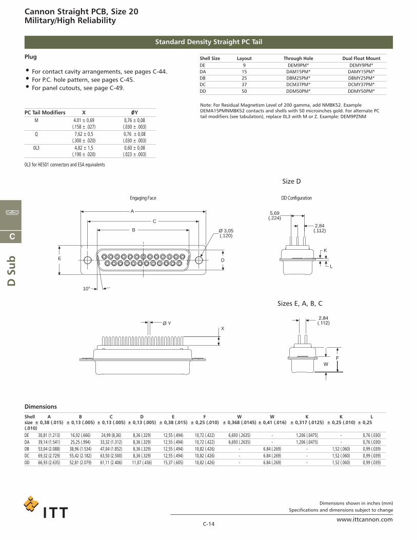
Cannon Straight PCB, Size 20Military/High Reliability
Standard Density Straight PC Tail
C-14www.ittcannon.com
Dimensions shown in inches (mm)Specifications and dimensions subject to change
C
D S
ub
Shell Size Layout Through Hole Dual Float MountDE 9 DEM9PM* DEMY9PM*DA 15 DAM15PM* DAMY15PM*DB 25 DBM25PM* DBMY25PM*DC 37 DCM37PM* DCMY37PM*DD 50 DDM50PM* DDMY50PM*
Dimensions
Plug
• For contact cavity arrangements, see pages C-44.• For P.C. hole pattern, see pages C-45.• For panel cutouts, see page C-49.
Note: For Residual Magnetism Level of 200 gamma, add NMBK52. ExampleDEMA15PMNMBK52 contacts and shells with 50 microinches gold. For alternate PCtail modifiers (see tabulation), replace 0L3 with M or Z. Example: DEM9PZNM
Shell A B C D E F W W K K Lsize ± 0,38 (.015) ± 0,13 (.005) ± 0,13 (.005) ± 0,13 (.005) ± 0,38 (.015) ± 0,25 (.010) ± 0,368 (.0145) ± 0,41 (.016) ± 0,317 (.0125) ± 0,25 (.010) ± 0,25(.010)DE 30,81 (1.213) 16,92 (.666) 24,99 (8,36) 8,36 (.329) 12,55 (.494) 10,72 (.422) 6,693 (.2635) - 1,206 (.0475) - 0,76 (.030)DA 39,14 (1.541) 25,25 (.994) 33,32 (1.312) 8,36 (.329) 12,55 (.494) 10,72 (.422) 6,693 (.2635) - 1,206 (.0475) - 0,76 (.030)DB 53,04 (2.088) 38,96 (1.534) 47,04 (1.852) 8,36 (.329) 12,55 (.494) 10,82 (.426) - 6.84 (.269) - 1,52 (.060) 0,99 (.039)DC 69,32 (2.729) 55,42 (2.182) 63,50 (2.500) 8,36 (.329) 12,55 (.494) 10,82 (.426) - 6.84 (.269) - 1,52 (.060) 0,99 (.039)DD 66,93 (2.635) 52,81 (2.079) 61,11 (2.406) 11,07 (.436) 15,37 (.605) 10,82 (.426) - 6.84 (.269) - 1,52 (.060) 0,99 (.039)
noitarugifnoC DDecaF gnigagnE
A
B
C
10°
E D
Ø 3,05(.120)
XØ Y
2,84(.112)
5,69(.224)
L
K
Sizes E, A, B, C
Size D
PC Tail Modifiers X ØYM 4.01 ± 0,69 0,76 ± 0,08
(.158 ± .027) (.030 ± .003)Q 7,62 ± 0,5 0,76 ± 0,08
(.300 ± .020) (.030 ± .003)0L3 4,82 ± 1,5 0,60 ± 0,08
(.190 ± .020) (.023 ± .003)
0L3 for HE501 connectors and ESA equivalents
ca_C1-C61.qxd:Layout 1 2/10/11 9:32 AM Page 14
C
D Su
b
C-15www.ittcannon.com
Dimensions shown in inches (mm)Specifications and dimensions subject to change
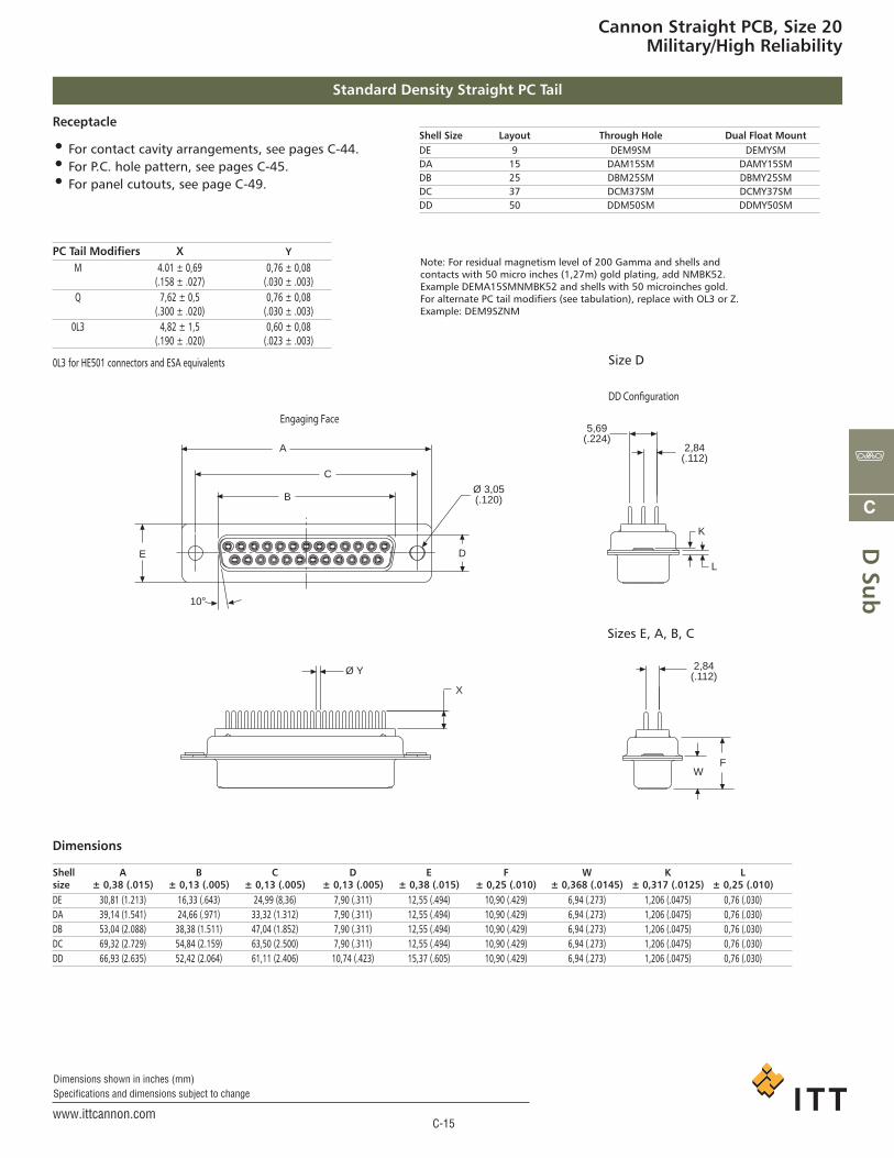
Cannon Straight PCB, Size 20Military/High Reliability
Standard Density Straight PC Tail
Shell Size Layout Through Hole Dual Float MountDE 9 DEM9SM DEMYSMDA 15 DAM15SM DAMY15SMDB 25 DBM25SM DBMY25SMDC 37 DCM37SM DCMY37SMDD 50 DDM50SM DDMY50SM
Dimensions
Receptacle
• For contact cavity arrangements, see pages C-44.• For P.C. hole pattern, see pages C-45.• For panel cutouts, see page C-49.
Note: For residual magnetism level of 200 Gamma and shells and contacts with 50 micro inches (1,27m) gold plating, add NMBK52. Example DEMA15SMNMBK52 and shells with 50 microinches gold. For alternate PC tail modifiers (see tabulation), replace with OL3 or Z. Example: DEM9SZNM
Shell A B C D E F W K Lsize ± 0,38 (.015) ± 0,13 (.005) ± 0,13 (.005) ± 0,13 (.005) ± 0,38 (.015) ± 0,25 (.010) ± 0,368 (.0145) ± 0,317 (.0125) ± 0,25 (.010)DE 30,81 (1.213) 16,33 (.643) 24,99 (8,36) 7,90 (.311) 12,55 (.494) 10,90 (.429) 6,94 (.273) 1,206 (.0475) 0,76 (.030)DA 39,14 (1.541) 24,66 (.971) 33,32 (1.312) 7,90 (.311) 12,55 (.494) 10,90 (.429) 6,94 (.273) 1,206 (.0475) 0,76 (.030)DB 53,04 (2.088) 38,38 (1.511) 47,04 (1.852) 7,90 (.311) 12,55 (.494) 10,90 (.429) 6,94 (.273) 1,206 (.0475) 0,76 (.030)DC 69,32 (2.729) 54,84 (2.159) 63,50 (2.500) 7,90 (.311) 12,55 (.494) 10,90 (.429) 6,94 (.273) 1,206 (.0475) 0,76 (.030)DD 66,93 (2.635) 52,42 (2.064) 61,11 (2.406) 10,74 (.423) 15,37 (.605) 10,90 (.429) 6,94 (.273) 1,206 (.0475) 0,76 (.030)
Engaging Face
DD Configuration
A
B
C
10°
E D
Ø 3,05(.120)
Ø Y
X
2,84(.112)
5,69(.224)
L
K
2,84(.112)
FW
Sizes E, A, B, C
Size D
PC Tail Modifiers X Y
M 4.01 ± 0,69 0,76 ± 0,08(.158 ± .027) (.030 ± .003)
Q 7,62 ± 0,5 0,76 ± 0,08(.300 ± .020) (.030 ± .003)
0L3 4,82 ± 1,5 0,60 ± 0,08(.190 ± .020) (.023 ± .003)
0L3 for HE501 connectors and ESA equivalents
ca_C1-C61.qxd:Layout 1 2/10/11 9:32 AM Page 15
C
D S
ub
C-16www.ittcannon.com
Dimensions shown in inches (mm)Specifications and dimensions subject to change
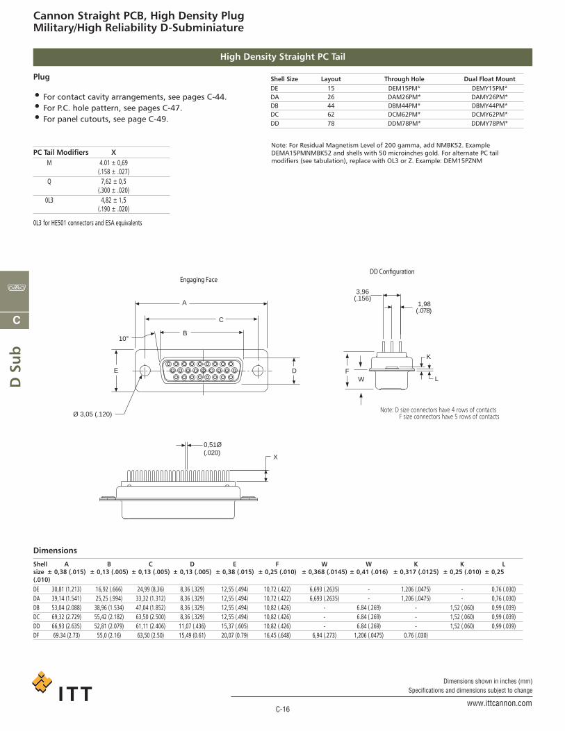
Cannon Straight PCB, High Density PlugMilitary/High Reliability D-Subminiature
High Density Straight PC Tail
Shell Size Layout Through Hole Dual Float MountDE 15 DEM15PM* DEMY15PM*DA 26 DAM26PM* DAMY26PM*DB 44 DBM44PM* DBMY44PM*DC 62 DCM62PM* DCMY62PM*DD 78 DDM78PM* DDMY78PM*
Dimensions
Plug
• For contact cavity arrangements, see pages C-44.• For P.C. hole pattern, see pages C-47.• For panel cutouts, see page C-49.
Note: For Residual Magnetism Level of 200 gamma, add NMBK52. ExampleDEMA15PMNMBK52 and shells with 50 microinches gold. For alternate PC tailmodifiers (see tabulation), replace with OL3 or Z. Example: DEM15PZNM
Shell A B C D E F W W K K Lsize ± 0,38 (.015) ± 0,13 (.005) ± 0,13 (.005) ± 0,13 (.005) ± 0,38 (.015) ± 0,25 (.010) ± 0,368 (.0145) ± 0,41 (.016) ± 0,317 (.0125) ± 0,25 (.010) ± 0,25(.010)DE 30,81 (1.213) 16,92 (.666) 24,99 (8,36) 8,36 (.329) 12,55 (.494) 10,72 (.422) 6,693 (.2635) - 1,206 (.0475) - 0,76 (.030)DA 39,14 (1.541) 25,25 (.994) 33,32 (1.312) 8,36 (.329) 12,55 (.494) 10,72 (.422) 6,693 (.2635) - 1,206 (.0475) - 0,76 (.030)DB 53,04 (2.088) 38,96 (1.534) 47,04 (1.852) 8,36 (.329) 12,55 (.494) 10,82 (.426) - 6.84 (.269) - 1,52 (.060) 0,99 (.039)DC 69,32 (2.729) 55,42 (2.182) 63,50 (2.500) 8,36 (.329) 12,55 (.494) 10,82 (.426) - 6.84 (.269) - 1,52 (.060) 0,99 (.039)DD 66,93 (2.635) 52,81 (2.079) 61,11 (2.406) 11,07 (.436) 15,37 (.605) 10,82 (.426) - 6.84 (.269) - 1,52 (.060) 0,99 (.039)DF 69.34 (2.73) 55,0 (2.16) 63,50 (2.50) 15,49 (0.61) 20,07 (0.79) 16,45 (.648) 6,94 (.273) 1,206 (.0475) 0.76 (.030)
DD Configuration
0,51Ø(.020)
X
1,98(.078)
3,96(.156)
L
K
Engaging Face
A
C
B10°
E D
Ø 3,05 (.120)
FW
Note: D size connectors have 4 rows of contacts F size connectors have 5 rows of contacts
PC Tail Modifiers XM 4.01 ± 0,69
(.158 ± .027)Q 7,62 ± 0,5
(.300 ± .020)0L3 4,82 ± 1,5
(.190 ± .020)
0L3 for HE501 connectors and ESA equivalents
ca_C1-C61.qxd:Layout 1 2/10/11 9:32 AM Page 16