Embed Size (px)
Citation preview
Standards Guide Release 8.6.00
CA 2E

This documentation, which includes embedded help systems and electronically distributed materials, (hereinafter referred to as the “Documentation”) is for your informational purposes only and is subject to change or withdrawal by CA at any time.
This Documentation may not be copied, transferred, reproduced, disclosed, modified or duplicated, in whole or in part, without the prior written consent of CA. This Documentation is confidential and proprietary information of CA and may not be disclosed by you or used for any purpose other than as may be permitted in (i) a separate agreement between you and CA governing your use of the CA software to which the Documentation relates; or (ii) a separate confidentiality agreement between you and CA.
Notwithstanding the foregoing, if you are a licensed user of the software product(s) addressed in the Documentation, you may print or otherwise make available a reasonable number of copies of the Documentation for internal use by you and your employees in connection with that software, provided that all CA copyright notices and legends are affixed to each reproduced copy.
The right to print or otherwise make available copies of the Documentation is limited to the period during which the applicable license for such software remains in full force and effect. Should the license terminate for any reason, it is your responsibility to certify in writing to CA that all copies and partial copies of the Documentation have been returned to CA or destroyed.
TO THE EXTENT PERMITTED BY APPLICABLE LAW, CA PROVIDES THIS DOCUMENTATION “AS IS” WITHOUT WARRANTY OF ANY KIND, INCLUDING WITHOUT LIMITATION, ANY IMPLIED WARRANTIES OF MERCHANTABILITY, FITNESS FOR A PARTICULAR PURPOSE, OR NONINFRINGEMENT. IN NO EVENT WILL CA BE LIABLE TO YOU OR ANY THIRD PARTY FOR ANY LOSS OR DAMAGE, DIRECT OR INDIRECT, FROM THE USE OF THIS DOCUMENTATION, INCLUDING WITHOUT LIMITATION, LOST PROFITS, LOST INVESTMENT, BUSINESS INTERRUPTION, GOODWILL, OR LOST DATA, EVEN IF CA IS EXPRESSLY ADVISED IN ADVANCE OF THE POSSIBILITY OF SUCH LOSS OR DAMAGE.
The use of any software product referenced in the Documentation is governed by the applicable license agreement and such license agreement is not modified in any way by the terms of this notice.
The manufacturer of this Documentation is CA.
Provided with “Restricted Rights.” Use, duplication or disclosure by the United States Government is subject to the restrictions set forth in FAR Sections 12.212, 52.227-14, and 52.227-19(c)(1) - (2) and DFARS Section 252.227-7014(b)(3), as applicable, or their successors.
Copyright © 2011 CA. All rights reserved. All trademarks, trade names, service marks, and logos referenced herein belong to their respective companies.

Contact CA Technologies
Contact CA Support
For your convenience, CA Technologies provides one site where you can access the information you need for your Home Office, Small Business, and Enterprise CA Technologies products. At http://ca.com/support, you can access the following:
■ Online and telephone contact information for technical assistance and customer services
■ Information about user communities and forums
■ Product and documentation downloads
■ CA Support policies and guidelines
■ Other helpful resources appropriate for your product
Providing Feedback About Product Documentation
If you have comments or questions about CA Technologies product documentation, you can send a message to [email protected].
If you would like to provide feedback about CA Technologies product documentation, complete our short customer survey, which is available on the CA Support website at http://ca.com/docs.

Contents 5
Contents
Chapter 1: Overview 13
Purpose ...................................................................................................................................................................... 13
Related Information ................................................................................................................................................... 13
iSeries Guides ...................................................................................................................................................... 13
General IBM Guides ............................................................................................................................................ 14
Conventions ............................................................................................................................................................... 14
Terms Used in This Manual ........................................................................................................................................ 15
Introduction to iSeries Programming and Documentation Standards ....................................................................... 16
Importance of Standards .................................................................................................................................... 16
iSeries Standards ................................................................................................................................................. 17
Enforcing Standards ............................................................................................................................................ 19
Chapter 2: Naming Conventions 21
Naming Conventions .................................................................................................................................................. 21
Natural Language ....................................................................................................................................................... 21
Objects ....................................................................................................................................................................... 22
Object-Oriented Approach ......................................................................................................................................... 23
Planning a Naming Convention .................................................................................................................................. 24
OS/400 Entity and Object Types ......................................................................................................................... 25
Constraints on the Uniqueness of Names .................................................................................................................. 28
Constraints on Naming Conventions .......................................................................................................................... 29
OS/400 ................................................................................................................................................................ 29
RPG III .................................................................................................................................................................. 29
COBOL ................................................................................................................................................................. 29
UIM ..................................................................................................................................................................... 30
Nature of Distinctions ......................................................................................................................................... 31
Number of Distinctions ....................................................................................................................................... 32
Object-action Naming ......................................................................................................................................... 34
Recommendations .............................................................................................................................................. 35
CA 2E Naming Convention .................................................................................................................................. 35
For RPG III ............................................................................................................................................................ 36
Naming Convention Variation ............................................................................................................................. 37
For Objects .......................................................................................................................................................... 37
For Formats ......................................................................................................................................................... 39
For Fields ............................................................................................................................................................. 40
HLLs Other Than RPG III ...................................................................................................................................... 40
6 Standards Guide
Mnemonics ................................................................................................................................................................. 41
CA 2E Mnemonic System .................................................................................................................................... 41
Formulate New Mnemonics ................................................................................................................................ 41
CA 2E and Mnemonics ........................................................................................................................................ 42
CA 2E Naming Convention Exceptions ................................................................................................................ 42
Advantages of CA 2E Naming Convention .................................................................................................................. 43
Enforcing A Naming Convention ................................................................................................................................ 44
Chapter 3: IBM i General Design Standards 45
Design Methods ......................................................................................................................................................... 46
Contents of a Specification ................................................................................................................................. 47
Design Tools ........................................................................................................................................................ 47
Design Standards for User Interfaces ......................................................................................................................... 48
Ease of Use .......................................................................................................................................................... 49
Interface Consistency .......................................................................................................................................... 50
Transfer of Learning ............................................................................................................................................ 51
Modal Behavior ................................................................................................................................................... 51
Exploring and Backing Out .................................................................................................................................. 52
Recall Versus Recognition ................................................................................................................................... 53
Novice and Expert Paths ..................................................................................................................................... 54
Contextual Information ....................................................................................................................................... 55
Shipped Systems ................................................................................................................................................. 55
iSeries User Interface Implementation Components .......................................................................................... 56
Design Standards for Display Files .............................................................................................................................. 56
For the IBM Midrange ......................................................................................................................................... 56
CUA Panel Components ...................................................................................................................................... 57
iSeries Panel Layout Standards ........................................................................................................................... 58
Using Command Keys .......................................................................................................................................... 61
Using Selection Columns ..................................................................................................................................... 63
Subfile Design ...................................................................................................................................................... 64
Basic Panel Display Styles On iSeries ................................................................................................................... 64
Common Panel Display Variants ......................................................................................................................... 65
Design Standards for Printer Files .............................................................................................................................. 68
Standard Report Design Layout .......................................................................................................................... 68
Notes on Report Design ...................................................................................................................................... 69
Design Standards for Menus ...................................................................................................................................... 71
Menu Design Considerations .............................................................................................................................. 71
Grouping Items On Menus .................................................................................................................................. 71
Appearance of Menus ......................................................................................................................................... 72
Arranging Menus ................................................................................................................................................. 73
Tools for Creating Menus .................................................................................................................................... 74
Contents 7
Design Standards for Help Text .................................................................................................................................. 75
Help Text Design Considerations ........................................................................................................................ 75
Designing Help Text............................................................................................................................................. 76
Panel Help Text ................................................................................................................................................... 77
Command Help Text ............................................................................................................................................ 77
Menu Help Text ................................................................................................................................................... 77
Search Indexes .................................................................................................................................................... 78
Design Standards for Commands ............................................................................................................................... 78
Why Use Commands? ......................................................................................................................................... 79
Naming Conventions ........................................................................................................................................... 80
Design Standards ................................................................................................................................................. 82
Required Parameters for Commands .................................................................................................................. 90
Design Standards for Database Files .......................................................................................................................... 90
Design Goals ........................................................................................................................................................ 90
The Database of iSeries ....................................................................................................................................... 91
Considerations for Database File Design ............................................................................................................. 95
Design Standards for Programs ................................................................................................................................ 102
Design Goals ...................................................................................................................................................... 103
Program Types .................................................................................................................................................. 103
Choosing Standard Programs ............................................................................................................................ 104
Organizing Programs into Modules ................................................................................................................... 105
Program Modularization ................................................................................................................................... 107
Error Recovery .................................................................................................................................................. 108
Error Handling ................................................................................................................................................... 109
Record Locking .................................................................................................................................................. 110
Subfile Processing ............................................................................................................................................. 111
Journaling for Audit Trail Purposes ................................................................................................................... 111
Design Standards for Internationalization ............................................................................................................... 115
General Principles ............................................................................................................................................. 115
MRI Translation ................................................................................................................................................. 116
Considerations for MRI (text) Translation ......................................................................................................... 120
Using System Values ......................................................................................................................................... 125
Writing Text for Translation .............................................................................................................................. 127
Ideographic Support .......................................................................................................................................... 128
Chapter 4: General Coding Standards 135
Coding Principles ...................................................................................................................................................... 135
Standard Source File Names .................................................................................................................................... 136
Source File Member Names .............................................................................................................................. 136
Standards for Text Descriptions and Titles ....................................................................................................... 136
Common Source File Coding Standards ................................................................................................................... 138
8 Standards Guide
Standard Banners in Source .............................................................................................................................. 138
Copyright Notice in Source ............................................................................................................................... 138
Maintenance Comments in Source ................................................................................................................... 139
Formatting Source Code ................................................................................................................................... 140
DDS Coding Standards for Files ................................................................................................................................ 141
HLL Coding Standards for Programs ......................................................................................................................... 141
Program Layout ................................................................................................................................................. 142
Coding for iSeries .............................................................................................................................................. 149
Chapter 5: Coding Standards for Database Files 151
Data Dictionary/Field Reference File ....................................................................................................................... 152
Standard for Field Reference Files .................................................................................................................... 152
Physical and Logical Database Files .......................................................................................................................... 155
Database File Coding Standards: File Level ....................................................................................................... 155
Format Level ..................................................................................................................................................... 155
Field Level ......................................................................................................................................................... 156
Arrays ................................................................................................................................................................ 157
Coding Standards for Display Files ........................................................................................................................... 157
Related Design Utilities ..................................................................................................................................... 157
Coding Standards for Printer Files ............................................................................................................................ 164
Related Design Utilities ..................................................................................................................................... 165
General Considerations ..................................................................................................................................... 165
Coding Standards for HLL Programs ......................................................................................................................... 169
General Principles ............................................................................................................................................. 169
Coding Standards for CL Programs ........................................................................................................................... 169
Field Names in CL Programs .............................................................................................................................. 171
Coding Standards for RPG III Programs .................................................................................................................... 173
Program Layout ................................................................................................................................................. 173
RPG III Coding Structures and Program Logic ................................................................................................... 175
Format Names in RPG III ................................................................................................................................... 180
RPG III Field Names ........................................................................................................................................... 180
RPG III Subroutine and Label Names ................................................................................................................. 182
RPG III Parameter and Key Lists ........................................................................................................................ 184
RPG III Standard Indicators ............................................................................................................................... 186
Techniques in RPG III Programs ........................................................................................................................ 187
Coding Structures and Program Logic ............................................................................................................... 189
Coding Standards for COBOL Programs ................................................................................................................... 190
Language Standards .......................................................................................................................................... 190
Program Layout ................................................................................................................................................. 191
Naming Standards in COBOL ............................................................................................................................. 198
Handling Dates in COBOL .................................................................................................................................. 202
Contents 9
Coding Standards for PL/1 Programs ....................................................................................................................... 203
Program Layout ................................................................................................................................................. 204
Copy Books ........................................................................................................................................................ 209
PL/1 Coding Structures and Program Logic .............................................................................................................. 211
Standard Procedures ......................................................................................................................................... 213
Naming Standards ............................................................................................................................................. 216
PL/1 Procedure and Label Names ..................................................................................................................... 217
Command Coding Conventions ................................................................................................................................ 219
Layout of Command Definition Source ............................................................................................................. 219
Cross-reference Data ........................................................................................................................................ 221
Command processing programs (CPP) .............................................................................................................. 222
Command Validity Checking Programs ............................................................................................................. 223
Prompt Override Programs ............................................................................................................................... 224
Coding Standards for Messages ............................................................................................................................... 226
Prompt Messages .............................................................................................................................................. 226
Execution Messages .......................................................................................................................................... 228
Standards for Defining Messages ............................................................................................................................. 232
Monitoring for Generic Message Groups .......................................................................................................... 233
Message Handling by Interactive Programs ...................................................................................................... 235
Message Handling by Batch Programs .............................................................................................................. 237
Coding Standards for Help Text ................................................................................................................................ 238
General Considerations ..................................................................................................................................... 239
Help Text Modularization .................................................................................................................................. 240
General Coding Techniques .............................................................................................................................. 242
Coding Help Text for Commands ...................................................................................................................... 245
Coding Help Text for Panels .............................................................................................................................. 246
Coding Help Text for Menus ............................................................................................................................. 247
Designing Search Indexes .................................................................................................................................. 247
Chapter 6: Work Management Standards 249
Introduction ............................................................................................................................................................. 249
General Principles ............................................................................................................................................. 249
Shipped Work Management Objects ....................................................................................................................... 250
Work Management Objects in QGPL ................................................................................................................ 251
OS/400 Shipped Authorities .............................................................................................................................. 251
Naming Work Management Objects ................................................................................................................. 251
Job Descriptions ....................................................................................................................................................... 253
Queues ..................................................................................................................................................................... 253
Print File Direction .................................................................................................................................................... 254
Scheduling Print Output .................................................................................................................................... 255
User Profile and Security Standards ......................................................................................................................... 255
10 Standards Guide
User Profiles ...................................................................................................................................................... 256
Implementation of Security ..................................................................................................................................... 262
Operational Rights ............................................................................................................................................ 263
Generic Implementation of Security ................................................................................................................. 263
Using Libraries .......................................................................................................................................................... 267
Organizing a Development Environment .......................................................................................................... 268
Operational Flow for Objects and Source ......................................................................................................... 269
Naming Convention for Libraries ...................................................................................................................... 270
Use of Libraries ................................................................................................................................................. 272
Version Control ........................................................................................................................................................ 275
Object Versions ................................................................................................................................................. 276
Upward Compatibility ....................................................................................................................................... 276
Version Numbers .............................................................................................................................................. 277
Version Installation Procedures ........................................................................................................................ 277
Backup and Recovery ............................................................................................................................................... 279
Data Security ..................................................................................................................................................... 280
Recovering from Non-Catastrophic Failure ....................................................................................................... 280
Recovering from Catastrophic Failure ............................................................................................................... 281
Backing-Up ............................................................................................................................................................... 282
Organizing Objects for Backup .......................................................................................................................... 283
Backing Up Live Application Systems ................................................................................................................ 283
Backing Up Development Systems .................................................................................................................... 283
Backup Methods ............................................................................................................................................... 284
Chapter 7: Standards for Testing 287
Types of Testing ....................................................................................................................................................... 287
Program Testing ................................................................................................................................................ 287
System Testing .................................................................................................................................................. 288
Test Techniques ................................................................................................................................................ 289
Chapter 8: Documentation Standards 297
Considerations ......................................................................................................................................................... 298
Documenting Commands .................................................................................................................................. 301
Messages ........................................................................................................................................................... 302
Standards For Preparing Text Documentation .................................................................................................. 302
Chapter 9: Naming Convention Examples 309
Examples .................................................................................................................................................................. 309
Contents 11
Chapter 10: EJB Option Runtime Example 313
Nouns, Adjectives, and Verbs ................................................................................................................................... 313
Appendix A: Programming and Coding Examples 317
Field Reference File Example ................................................................................................................................... 317
Primary Reference Fields: "TYPE FIELDS" .......................................................................................................... 318
Secondary Reference Fields .............................................................................................................................. 318
Database File DDS Example ...................................................................................................................................... 321
Sample Physical File DDS ................................................................................................................................... 321
Sample Logical File DDS..................................................................................................................................... 322
Display File DDS Example ......................................................................................................................................... 322
Printer File DDS Example .......................................................................................................................................... 326
CL Program Source Example..................................................................................................................................... 329
RPG III Program Source Example .............................................................................................................................. 331
COBOL ‘85 Program Example ................................................................................................................................... 341
Command Source Example ...................................................................................................................................... 372
Command Diagram Example .................................................................................................................................... 373
YEDTLIBLST (Edit Library List) ............................................................................................................................ 373
General Rules for Preparing Command Diagrams .................................................................................................... 374
Example ............................................................................................................................................................. 375
Parameter Descriptions ............................................................................................................................................ 376
UIM Help Text Example ............................................................................................................................................ 377
Command Help (‘wlllcmH’) ............................................................................................................................... 378
Panel Help (‘wlllpnh’) ........................................................................................................................................ 381
Search Index (‘wschidx’) .................................................................................................................................... 383
Hypertext Definitions (‘wlllenh’) ....................................................................................................................... 386
Appendix B: Printer Form Sizes 389
Printer Form Standard Options ................................................................................................................................ 389
Index 391

Chapter 1: Overview 13
Chapter 1: Overview
This section contains the following topics:
Purpose (see page 13) Related Information (see page 13) Conventions (see page 14) Terms Used in This Manual (see page 15) Introduction to iSeries Programming and Documentation Standards (see page 16)
Purpose
This manual describes CA 2E design, documentation, and programming standards for IBM iSeries. It also details techniques and tools to support and facilitate the use of the standards, including CA 2E Toolkit and CA 2E products.
This manual covers both expected minimum standards and good practice in applying programming standards for iSeries. Where possible, the reason for the use of a standard is given as well as the standard itself. This manual does not advocate adopting any particular standard. It emphasizes the need for standards and their usefulness and provides considerations for choosing standards appropriate to IBM iSeries. In many cases, the rationale for the suggested standards rests on software engineering principles.
Related Information
Information that is available from either IBM manuals or CA 2E product guides is not repeated in this manual.
iSeries Guides
Documentation you may want to refer to in the context of using this manual is listed below. Relevant iSeries guides include the following:
■ IBM iSeries Programming: Control Language Programmer’s Guide (SC21-8077-0).
■ IBM iSeries Programming: Control Language Reference Volume 1 (SC21-9775-0), Volume 2 (SC21-9776-0), Volume 3 (SC21-9777-0), Volume 4 (SC21-9778-0), and Volume 5 (SC21-9779-0).
■ IBM iSeries Programming: Data Description Specifications (SC21-9620-0).
Conventions
14 Standards Guide
■ IBM iSeries Guide to Programming Application and Help Displays (SC41-0011)
■ IBM iSeries Defining Compatible Displays using DDS specifications (GC21-8136-0).
■ IBM iSeries National Language Support Planning Guide (GC41-9877-00)
Regarding performance considerations for iSeries, refer to the following:
■ RPG III Reference Manual
General IBM Guides
IBM guides that contain general information include the following:
■ IBM National Language Information and Design Guide Volume 1 (SE09-8001-00) and Volume 2 (SE09-8002-00).
■ IBM National Language Support Planning Guide (GC41-9877)
Conventions
This manual uses the following conventions:
■ Data entry text appears in caps for emphasis; however, you can enter the data in lower case.
■ All terms (commands, access paths, files, and fields) refer to CA 2E unless otherwise indicated, such as OS/400 Save Library (SAVLIB) command.
■ The first reference to features that have abbreviated names includes both the full and abbreviated name; for example, the Edit File (EDTFIL) function or National Language Support (NLS). Subsequently, only the abbreviated name identifies the feature.
Terms Used in This Manual
Chapter 1: Overview 15
Terms Used in This Manual
Descriptions of the acronyms used in this module are defined here in this chapter. In the text, both the full name and acronym are given the first time the term is used. Thereafter, only the acronym, value, or term is used.
ADT Abstract Data Type
API Application Program Interface
CPP Command Processing Program
CUA Common User Access
DBCS Double Byte Character System
FRF Field Reference File
IGC Ideographic Support
LTR Left to Right
MRI Machine Readable Information
NLS National Language Support
NPT Non-programmable Terminal
PDM Programming Development Manager
PASA Program using Automatic Storage Allocation
RTL Right to Left
SAA System Application Software
SDA Screen Design Aid
SBCS Single Byte Character Set
Introduction to iSeries Programming and Documentation Standards
16 Standards Guide
Introduction to iSeries Programming and Documentation Standards
The IBM midrange has grown to provide new and more powerful hardware (iSeries); additional High Level languages (HLL) such as PL/1, COBOL/400, C/400, REXX, FORTRAN; additional iSeries capabilities such as SQL/400, UIM Help, and Knowledge Tool/400; the system programming APIs; and new IBM tools such as Programming Development Manager (PDM) are also offered. Equally significant is the widespread adoption of software design and implementation tools, such as CA 2E products.
Although there is now more technology to cover, there are also some welcome developments that simplify the task. Both the industry in general and, IBM in particular, now give greater attention to common standards; for example, IBM’s System Application Architecture (SAA). IBM’s Common User Access (CUA) standard for user interface design has been rapidly and universally adopted within the IBM world. The need for and value of software tools is becoming better understood. Other helpful developments include the widespread understanding and adoption of object-oriented techniques and the realization that objects are of use not just in full object-oriented programming environments but also in a more limited role for design.
Importance of Standards
It is essential that you make an intelligent use of standards in order to take full advantage of the IBM midrange architecture. The OS/400 has many standards, both explicit and implicit, with which you need to conform in order to provide applications that are robust, maintainable, and easy to use.
Standards can be viewed as actual productivity tools. By adopting good standards, you can simplify both your design and development.
Standards reduce the amount of work you need to do to produce a given result. Those aspects of a specification that are covered by your normal standards can be removed from the picture, leaving only the essentials specific to the problem in hand to be solved. This can significantly reduce the amount time needed to communicate between people at all stages of the development process: design, programming, testing, and user training.
Standards can also improve the quality of your software. Good standards should embody established techniques for approaching commonly encountered development problems.
The inherent capabilities of IBM iSeries can be complemented by providing additional productivity tools that build upon OS/400. This manual provides you with indications of where such aids can be useful.
Introduction to iSeries Programming and Documentation Standards
Chapter 1: Overview 17
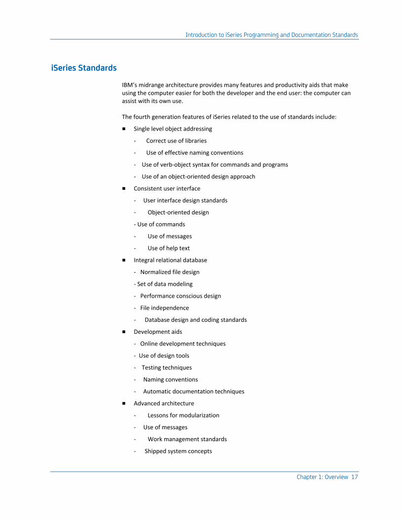
iSeries Standards
IBM’s midrange architecture provides many features and productivity aids that make using the computer easier for both the developer and the end user: the computer can assist with its own use.
The fourth generation features of iSeries related to the use of standards include:
■ Single level object addressing
- Correct use of libraries
- Use of effective naming conventions
- Use of verb-object syntax for commands and programs
- Use of an object-oriented design approach
■ Consistent user interface
- User interface design standards
- Object-oriented design
- Use of commands
- Use of messages
- Use of help text
■ Integral relational database
- Normalized file design
- Set of data modeling
- Performance conscious design
- File independence
- Database design and coding standards
■ Development aids
- Online development techniques
- Use of design tools
- Testing techniques
- Naming conventions
- Automatic documentation techniques
■ Advanced architecture
- Lessons for modularization
- Use of messages
- Work management standards
- Shipped system concepts
Introduction to iSeries Programming and Documentation Standards
18 Standards Guide
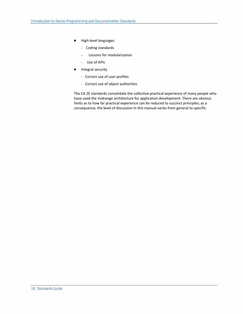
■ High-level languages
- Coding standards
- Lessons for modularization
- Use of APIs
■ Integral security
- Correct use of user profiles
- Correct use of object authorities
The CA 2E standards consolidate the collective practical experience of many people who have used the midrange architecture for application development. There are obvious limits as to how far practical experience can be reduced to succinct principles; as a consequence, the level of discussion in this manual varies from general to specific.
Introduction to iSeries Programming and Documentation Standards
Chapter 1: Overview 19
Enforcing Standards
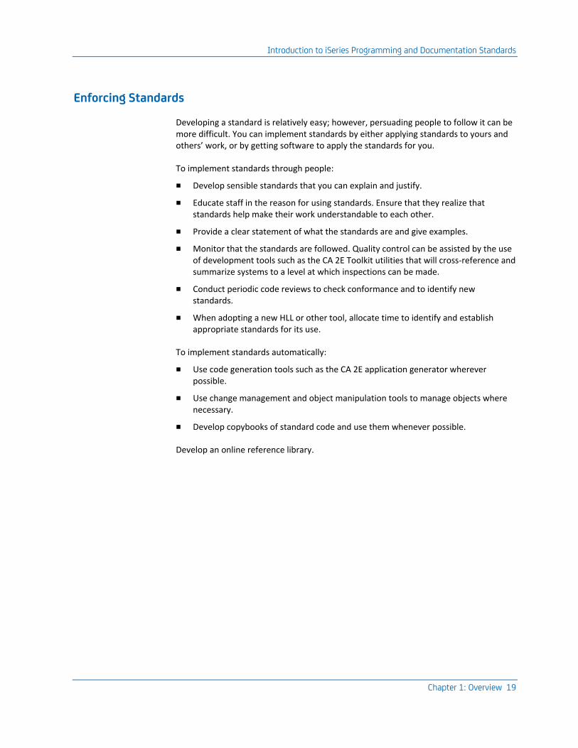
Developing a standard is relatively easy; however, persuading people to follow it can be more difficult. You can implement standards by either applying standards to yours and others’ work, or by getting software to apply the standards for you.
To implement standards through people:
■ Develop sensible standards that you can explain and justify.
■ Educate staff in the reason for using standards. Ensure that they realize that standards help make their work understandable to each other.
■ Provide a clear statement of what the standards are and give examples.
■ Monitor that the standards are followed. Quality control can be assisted by the use of development tools such as the CA 2E Toolkit utilities that will cross-reference and summarize systems to a level at which inspections can be made.
■ Conduct periodic code reviews to check conformance and to identify new standards.
■ When adopting a new HLL or other tool, allocate time to identify and establish appropriate standards for its use.
To implement standards automatically:
■ Use code generation tools such as the CA 2E application generator wherever possible.
■ Use change management and object manipulation tools to manage objects where necessary.
■ Develop copybooks of standard code and use them whenever possible.
Develop an online reference library.

Chapter 2: Naming Conventions 21
Chapter 2: Naming Conventions
A naming convention is a systematic method for allocating names to things. This chapter describes the CA 2E recommended method for establishing your naming conventions.
This section contains the following topics:
Naming Conventions (see page 21) Natural Language (see page 21) Objects (see page 22) Object-Oriented Approach (see page 23) Planning a Naming Convention (see page 24) Constraints on the Uniqueness of Names (see page 28) Constraints on Naming Conventions (see page 29) Mnemonics (see page 41) Advantages of CA 2E Naming Convention (see page 43) Enforcing A Naming Convention (see page 44)
Naming Conventions
Naming conventions assume a particular importance on iSeries for a number of reasons. The Single Level Object Addressing of the OS/400 architecture means that the fundamental software entities exist within a flat hierarchy of only two levels¾library and object. While this has many benefits, it also means that name conflicts are more likely, and that the context in which an object is found does not necessarily give information about its purpose or nature.
The maximum lengths allowed for the names of most types of OS/400 entities are relatively short; ten characters is standard. This means that where there are large populations of an entity, you need to plan to avoid conflicts.
One of the fundamental strengths of the OS/400 is its consistent user interface. In some cases, this requires that objects be named to conform with OS/400’s implicit rules for naming objects that are visible to an end user.
Natural Language
You do not use names to only provide unique identifiers; you also use names to classify the identified objects in order to recognize them. This is the basis of an OS/400 naming convention.
Objects
22 Standards Guide
Objects
The OS/400 operating system is object-based; this means the fundamental software entities on the iSeries can be understood and manipulated as objects existing within a uniform, simple conceptual framework. All OS/400 objects have certain common properties; for example, a name, a creation date, an owner; and can be subjected to certain common methods, such as saving, moving, and deleting.
Objects ensure better integrity and better modularization. The OS/400 objects also provide a simple intuitive way of understanding system software. The statements of OS/400’s CL command language have highly uniform verb/object syntax; for example Create Data area (CRTDTAARA), Delete data area (DLTDTAARA), Display data area (DSPDTAARA). You may consider this as being similar to the imperative tense used for simple English commands such as "Read this" or "Stop that." The distinction between objects and the methods that operate on them corresponds to the noun/verb distinction found in natural languages.
By adopting a consistent syntax in its commands and other interfaces, OS/400 is able to harness our innate capabilities to generalize rules and formulate new instances so that you can successfully use new software or cope with new situations.
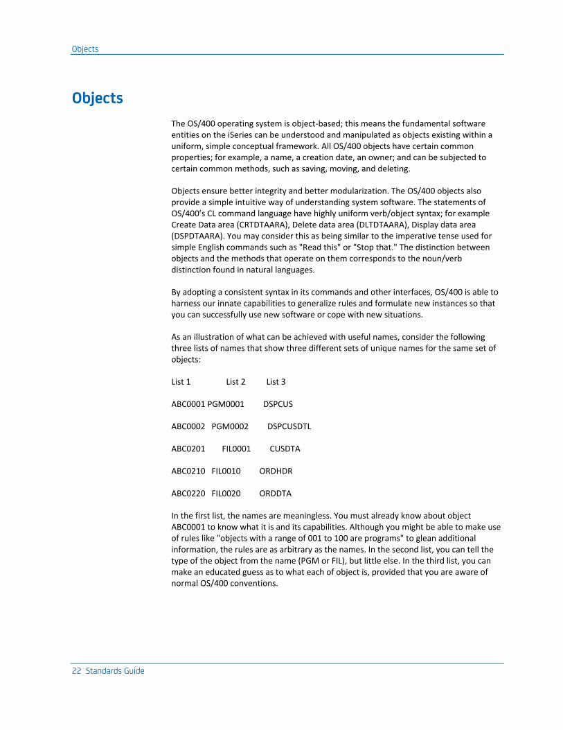
As an illustration of what can be achieved with useful names, consider the following three lists of names that show three different sets of unique names for the same set of objects:
List 1 List 2 List 3
ABC0001 PGM0001 DSPCUS
ABC0002 PGM0002 DSPCUSDTL
ABC0201 FIL0001 CUSDTA
ABC0210 FIL0010 ORDHDR
ABC0220 FIL0020 ORDDTA
In the first list, the names are meaningless. You must already know about object ABC0001 to know what it is and its capabilities. Although you might be able to make use of rules like "objects with a range of 001 to 100 are programs" to glean additional information, the rules are as arbitrary as the names. In the second list, you can tell the type of the object from the name (PGM or FIL), but little else. In the third list, you can make an educated guess as to what each of object is, provided that you are aware of normal OS/400 conventions.
Object-Oriented Approach
Chapter 2: Naming Conventions 23
In doing so, you are employing naturalistic mechanisms: the use of a limited vocabulary of "words" which always have a similar meaning, (DSP-Display, DTA-Data), and the use of a simple syntax. The essence of the syntax is to use a simple imperative verb word (DSP) followed by an object word (CUS) to indicate a procedural verb object (DSPCUS), as opposed to an adjective (CUS) and a noun (DTA) to indicate a passive noun object (CUSDTA). A third point to note is that the OS/400 convention for systematically deriving mnemonics from significant consonants is naturalistic as consonants are generally more easily remembered.
Object-Oriented Approach
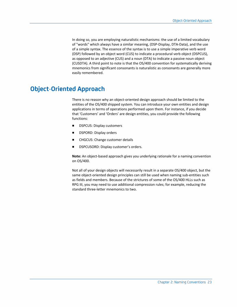
There is no reason why an object-oriented design approach should be limited to the entities of the OS/400 shipped system. You can introduce your own entities and design applications in terms of operations performed upon them. For instance, if you decide that ‘Customers’ and ‘Orders’ are design entities, you could provide the following functions:
■ DSPCUS: Display customers
■ DSPORD: Display orders
■ CHGCUS: Change customer details
■ DSPCUSORD: Display customer’s orders.
Note: An object-based approach gives you underlying rationale for a naming convention on OS/400.
Not all of your design objects will necessarily result in a separate OS/400 object, but the same object-oriented design principles can still be used when naming sub-entities such as fields and members. Because of the strictures of some of the OS/400 HLLs such as RPG III, you may need to use additional compression rules; for example, reducing the standard three-letter mnemonics to two.
Planning a Naming Convention
24 Standards Guide
Planning a Naming Convention
A naming convention for iSeries should do the following:
■ be applicable to entities at all levels. OS/400 entities include all OS/400 object types, files, formats, fields, and members
■ be rule-based. It should be possible to generate a new name or to analyze an old one by a rule, rather than by referring to a table or central log. The rules should be based on relevant categories of distinction; for instance, properties of the entities being named that are important in distinguishing them from other entities of the same type. You may want to distinguish between database files by both the file type (physical/logical) and the nature of the file’s contents (transient/permanent); you will want to distinguish between programs by their function.
■ encode as much useful information as possible within the names it generates about the role of the entity, and its relation to other entities. Similarly, it should not contain irrelevant information.
■ be easy to remember. Simplicity, consistency, and adherence to natural language principles will facilitate this.
■ use the same name for an entity wherever it is used. For example, it should not be necessary to explicitly rename fields to overcome the limitations of a particular HLL, such as with RPG III.
■ be as compatible as possible with other standards, notably those inherent in the OS/400 shipped system. For example, no object name should begin with the letter ‘Q’, which is reserved for IBM-supplied objects.
There are three separate interfaces in the OS/400 architecture with which you should be consistent:
■ The Control Language
■ The DDS Database description language
■ The System displays and printouts
The CL command language interface in particular suggests certain naming practices; for example, use OS/400 mnemonics such as DSP for display wherever possible.
Follow an object-action system. Name objects that perform a function (commands and programs) according to the action they perform upon an object or entity; use the form ‘verb + object’. For objects that have actions performed upon them (as files, data areas, message queues), base their names on the significant entity that they represent; use the form ‘object’ or ‘adjective + object’. For example, Display Active Jobs (DSPACTJOB), Date format system value (QDATFMT), Batch subsystem (QBATCH).
Planning a Naming Convention
Chapter 2: Naming Conventions 25
Allow the names generated by the convention to lend themselves to generic manipulation. This means adopting names that give useful generic names for manipulation by CL commands. Also, ensure that names are tractable by the scan functions of source editor utilities such as SEU and object manipulation tools such as IBM’s Programming Development Manager (PDM). A generic name, indicated by an asterisk at the last position, encompasses the names of all entities, which begin with the same character string. For example, AB* implies all entities whose names begin with the letters AB.
Because of the limitations of the CL generic name, it is almost impossible to come up with a naming convention that completely satisfies this requirement. If you include indications of both an object’s type and its function in a name, one must be given precedence. Since sometimes you may want to manipulate objects by type, yet at other times by functional group, there inevitably can be a conflict. The floating generic name (*XXX*) capabilities of PDM can be used for generic manipulation on lower order parts of the name, provided you have adopted a convention that ensures related objects have at least some related component to their names.
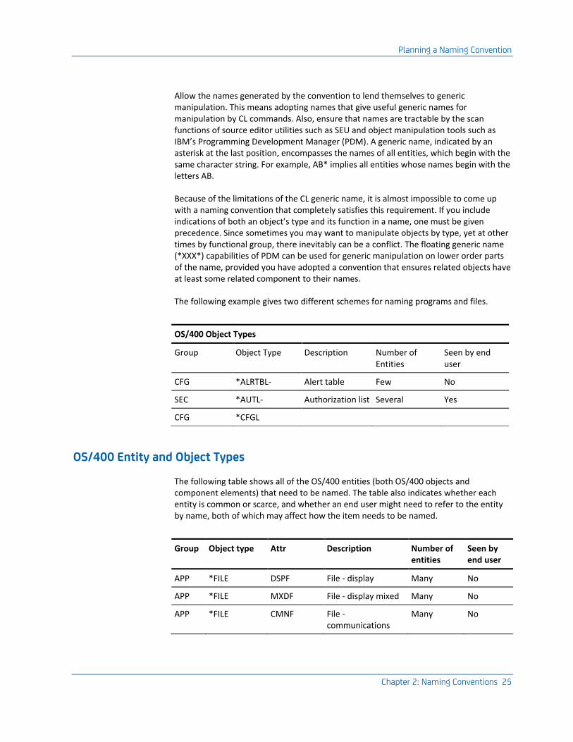
The following example gives two different schemes for naming programs and files.
OS/400 Object Types
Group Object Type Description Number of Entities
Seen by end user
CFG *ALRTBL- Alert table Few No
SEC *AUTL- Authorization list Several Yes
CFG *CFGL
OS/400 Entity and Object Types
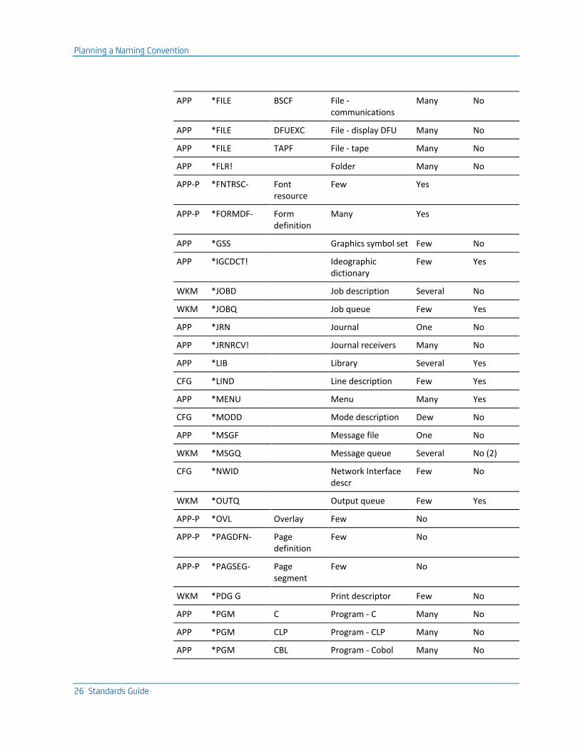
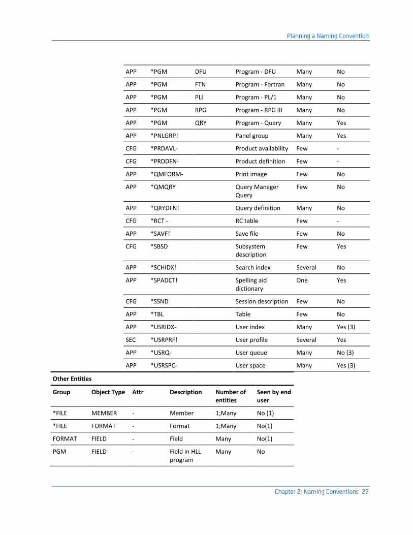
The following table shows all of the OS/400 entities (both OS/400 objects and component elements) that need to be named. The table also indicates whether each entity is common or scarce, and whether an end user might need to refer to the entity by name, both of which may affect how the item needs to be named.
Group Object type Attr Description Number of entities
Seen by end user
APP *FILE DSPF File - display Many No
APP *FILE MXDF File - display mixed Many No
APP *FILE CMNF File - communications
Many No
Planning a Naming Convention
26 Standards Guide
APP *FILE BSCF File - communications
Many No
APP *FILE DFUEXC File - display DFU Many No
APP *FILE TAPF File - tape Many No
APP *FLR! Folder Many No
APP-P *FNTRSC- Font resource
Few Yes
APP-P *FORMDF- Form definition
Many Yes
APP *GSS Graphics symbol set Few No
APP *IGCDCT! Ideographic dictionary
Few Yes
WKM *JOBD Job description Several No
WKM *JOBQ Job queue Few Yes
APP *JRN Journal One No
APP *JRNRCV! Journal receivers Many No
APP *LIB Library Several Yes
CFG *LIND Line description Few Yes
APP *MENU Menu Many Yes
CFG *MODD Mode description Dew No
APP *MSGF Message file One No
WKM *MSGQ Message queue Several No (2)
CFG *NWID Network Interface descr
Few No
WKM *OUTQ Output queue Few Yes
APP-P *OVL Overlay Few No
APP-P *PAGDFN- Page definition
Few No
APP-P *PAGSEG- Page segment
Few No
WKM *PDG G Print descriptor Few No
APP *PGM C Program - C Many No
APP *PGM CLP Program - CLP Many No
APP *PGM CBL Program - Cobol Many No
Planning a Naming Convention
Chapter 2: Naming Conventions 27
APP *PGM DFU Program - DFU Many No
APP *PGM FTN Program - Fortran Many No
APP *PGM PLI Program - PL/1 Many No
APP *PGM RPG Program - RPG III Many No
APP *PGM QRY Program - Query Many Yes
APP *PNLGRP! Panel group Many Yes
CFG *PRDAVL- Product availability Few -
CFG *PRDDFN- Product definition Few -
APP *QMFORM- Print image Few No
APP *QMQRY Query Manager Query
Few No
APP *QRYDFN! Query definition Many No
CFG *RCT - RC table Few -
APP *SAVF! Save file Few No
CFG *SBSD Subsystem description
Few Yes
APP *SCHIDX! Search index Several No
APP *SPADCT! Spelling aid dictionary
One Yes
CFG *SSND Session description Few No
APP *TBL Table Few No
APP *USRIDX- User index Many Yes (3)
SEC *USRPRF! User profile Several Yes
APP *USRQ- User queue Many No (3)
APP *USRSPC- User space Many Yes (3)
Other Entities
Group Object Type Attr Description Number of entities
Seen by end user
*FILE MEMBER - Member 1;Many No (1)
*FILE FORMAT - Format 1;Many No(1)
FORMAT FIELD - Field Many No(1)
PGM FIELD - Field in HLL program
Many No
Constraints on the Uniqueness of Names
28 Standards Guide
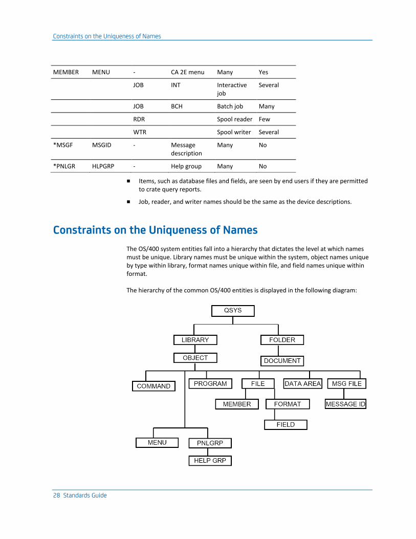
MEMBER MENU - CA 2E menu Many Yes
JOB INT Interactive job
Several
JOB BCH Batch job Many
RDR Spool reader Few
WTR Spool writer Several
*MSGF MSGID - Message description
Many No
*PNLGR HLPGRP - Help group Many No
■ Items, such as database files and fields, are seen by end users if they are permitted to crate query reports.
■ Job, reader, and writer names should be the same as the device descriptions.
Constraints on the Uniqueness of Names
The OS/400 system entities fall into a hierarchy that dictates the level at which names must be unique. Library names must be unique within the system, object names unique by type within library, format names unique within file, and field names unique within format.
The hierarchy of the common OS/400 entities is displayed in the following diagram:
Constraints on Naming Conventions
Chapter 2: Naming Conventions 29
Constraints on Naming Conventions
Each programming language has specific naming characteristics you need to be aware of which are described in the following section.
OS/400
OS/400 simple names may have a maximum of ten alphabetic characters: the first character must be alphabetic or a special character such as ‘@’, ‘$’, or ‘#’. Embedded blanks are not allowed. This restriction applies to object names, member names, format names, and field names in CL, command source, and DDS. The names of OS/400 objects, folder, and document names may also contain an embedded period; for example ‘FRED.DOC’.
The user profile names used in networks should be eight characters or less, as some other architectures only support eight-character names.
RPG III
RPG III field names may have a maximum of six characters.
File names in RPG III Calculation specifications may have a maximum of eight characters. This is also true in File specifications, although a database override can be used to associate this eight-character name with an actual file possessing a longer name.
A program call statement is executed more efficiently in RPG III if the name of the program being called can be coded as a literal. This requires that program names are restricted to eight characters maximum.
Within an RPG III program, field names are global: they cannot be local to a particular subroutine, nor may they be qualified by the name of the file or format with which they are associated. This means they need to be unique within the program. In order to avoid having to rename fields, and also to be able to relate fields to formats, you may want to provide an indication of the format in the field name.
COBOL
Characters other than the letters of the alphabet, digits, and the hyphen, for example &, #, @), are not allowed.
Constraints on Naming Conventions
30 Standards Guide
UIM
* # and ‘@’ are not allowed in label names.
Several psychological factors are also relevant. Human short-term memory has difficulty retaining more than seven (plus or minus two) "chunks" of information. This is significant if unfamiliar names have to be remembered for short periods of time; for instance, when noting down the name of a program that has crashed, or when looking up a code value for an input display.
Remembering an arbitrary code such as ‘X1274ZF’ is more difficult than remembering a meaningful one of equivalent length which can be "chunked" into a lower number of known components. For example, although ‘UDSPCUS’ is also seven letters long, to someone familiar with OS/400 naming conventions it can be remembered as only three elements (U + DSP + CUS).
Where a name is made up of subcodes, the number of possible ambiguous interpretations is greatly reduced if the subcodes always have the same starting positions and lengths. For instance, knowing that a name (CUSCDE) is made up of two mnemonics, each three characters long, you stand a fair chance of guessing what it represents:
CUS + CDE = Customer code
If, on the other hand, it could also be made of any other combination of abbreviations, guessing is more difficult:
■ C + US + CDE = Carolina USA code?
■ CU + S + CDE = Customer salary code?
■ CUS-C + DE = Customer complaints department?
■ CU + SCD + E = Custom security code entry?
The most efficient (giving maximum recognizability for minimal size) form of mnemonic is three characters long, as in most CL mnemonics.
Consonants are generally more significant for distinguishing names than vowels. The information content of a consonant (which distinguishes between from around twenty other letters) is greater than that of a vowel (which distinguishes from about five other vowels).
For example:
Contrast: ..a. .oe. ..i. .a.?
with: wh . t d . . s th. s s . y?
It is easier to carry out pattern matching on items that are strictly comparable. A column of names is easier to scan if the names are aligned as shown in the following example.
Constraints on Naming Conventions
Chapter 2: Naming Conventions 31
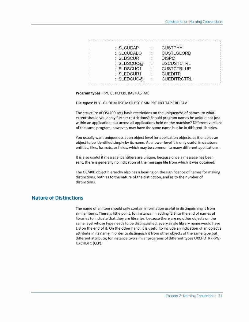
Program types: RPG CL PLI CBL BAS PAS (MI)
File types: PHY LGL DDM DSP MXD BSC CMN PRT DKT TAP CRD SAV
The structure of OS/400 sets basic restrictions on the uniqueness of names: to what extent should you apply further restrictions? Should program names be unique not just within an application, but across all applications held on the machine? Different versions of the same program, however, may have the same name but be in different libraries.
You usually want uniqueness at an object level for application objects, as it enables an object to be identified simply by its name. At a lower level it is only useful in database entities, files, formats, or fields, which may be common to many different applications.
It is also useful if message identifiers are unique, because once a message has been sent, there is generally no indication of the message file from which it was obtained.
The OS/400 object hierarchy also has a bearing on the significance of names for making distinctions, both as to the nature of the distinction, and as to the number of distinctions.
Nature of Distinctions
The name of an item should only contain information useful in distinguishing it from similar items. There is little point, for instance, in adding ‘LIB’ to the end of names of libraries to indicate that they are libraries, because there are no other objects on the same level whose type needs to be distinguished: every single library name would have LIB on the end of it. On the other hand, it is useful to include an indication of an object’s attribute in its name in order to distinguish it from other objects of the same type but different attribute; for instance two similar programs of different types UXCHDTR (RPG) UXCHDTC (CLP).
Constraints on Naming Conventions
32 Standards Guide
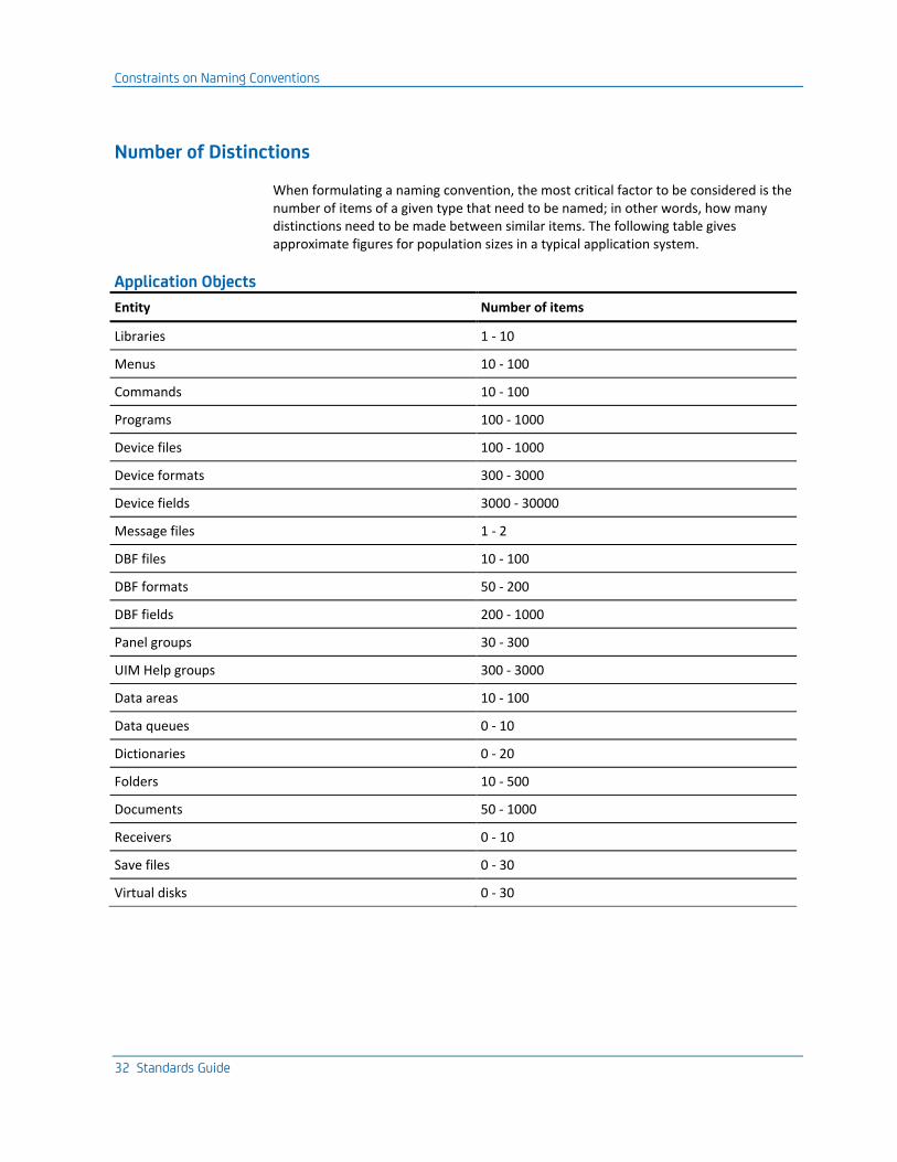
Number of Distinctions
When formulating a naming convention, the most critical factor to be considered is the number of items of a given type that need to be named; in other words, how many distinctions need to be made between similar items. The following table gives approximate figures for population sizes in a typical application system.
Application Objects
Entity Number of items
Libraries 1 - 10
Menus 10 - 100
Commands 10 - 100
Programs 100 - 1000
Device files 100 - 1000
Device formats 300 - 3000
Device fields 3000 - 30000
Message files 1 - 2
DBF files 10 - 100
DBF formats 50 - 200
DBF fields 200 - 1000
Panel groups 30 - 300
UIM Help groups 300 - 3000
Data areas 10 - 100
Data queues 0 - 10
Dictionaries 0 - 20
Folders 10 - 500
Documents 50 - 1000
Receivers 0 - 10
Save files 0 - 30
Virtual disks 0 - 30
Constraints on Naming Conventions
Chapter 2: Naming Conventions 33
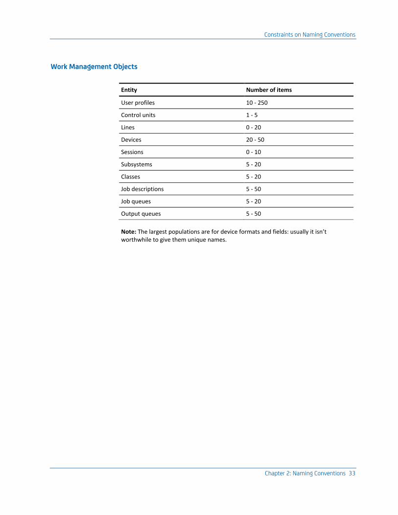
Work Management Objects
Entity Number of items
User profiles 10 - 250
Control units 1 - 5
Lines 0 - 20
Devices 20 - 50
Sessions 0 - 10
Subsystems 5 - 20
Classes 5 - 20
Job descriptions 5 - 50
Job queues 5 - 20
Output queues 5 - 50
Note: The largest populations are for device formats and fields: usually it isn’t worthwhile to give them unique names.
Constraints on Naming Conventions
34 Standards Guide
Object-action Naming
Under an object-action approach to naming, in line with an object-oriented approach to design, distinguish between:
■ those items that implement a process; for example programs or commands. (Actions)
■ those items that are operated upon by a process; for example, database files or data areas. (Objects)
This distinction can be seen in OS/400. Things upon which you operate (QPRINT, QBATCH, QINTER), are named differently from the things you use to perform the operation, which are named after the operation itself; for instance DSP (DSPSBS, DSPOUTQ), or CRT (CRTSBSD, CRTOUTQ).
Name all objects needed to implement a process after the process (programs and device files); and all objects that are operated on by processes (subjects of actions) by what they represent.
This allows you to identify all the objects needed to run a given command or a HLL program, apart from application-wide objects, which is assumed to be generally needed.
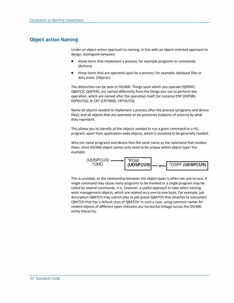
Why not name programs and device files the same name as the command that invokes them, since OS/400 object names only need to be unique within object type? For example:
This is unviable, as the relationship between the object types is often not one-to-one. A single command may cause many programs to be invoked or a single program may be called by several commands. It is, however, a useful approach to take when naming work management objects, which are related on a one-to-one basis. For example, job description QBATCH may submit jobs to job queue QBATCH that attaches to subsystem QBATCH that has a default class of QBATCH. In such a case, using common names for related objects of different types indicates any horizontal linkage across the OS/400 entity hierarchy.
Constraints on Naming Conventions
Chapter 2: Naming Conventions 35
Recommendations
■ Use a variation of OS/400 and convention for those object types that are scarce, or that are referred to directly by the end user.
- Use OS/400 type mnemonics to name such objects and use a single letter prefix to identify the application.
- Use the form verb/noun for action-based names.
- Use the form noun or adj/noun for subject based names.
- Use work management objects (QPRINT and QPGMR) as shipped.
■ Use a separate systematic convention, outlined below, for entities that occur in large numbers and which are normally referred to only by technical personnel.
IBM has adopted a similar approach for the system software of iSeries, as may be seen from the names of the objects in the system library, QSYS, or other shipped libraries such as QGPL, QRPG, QIDU. Internal objects, such as programs, are named, using systematic prefixes.
CA 2E Naming Convention
The CA 2E naming conventions are described in this section.
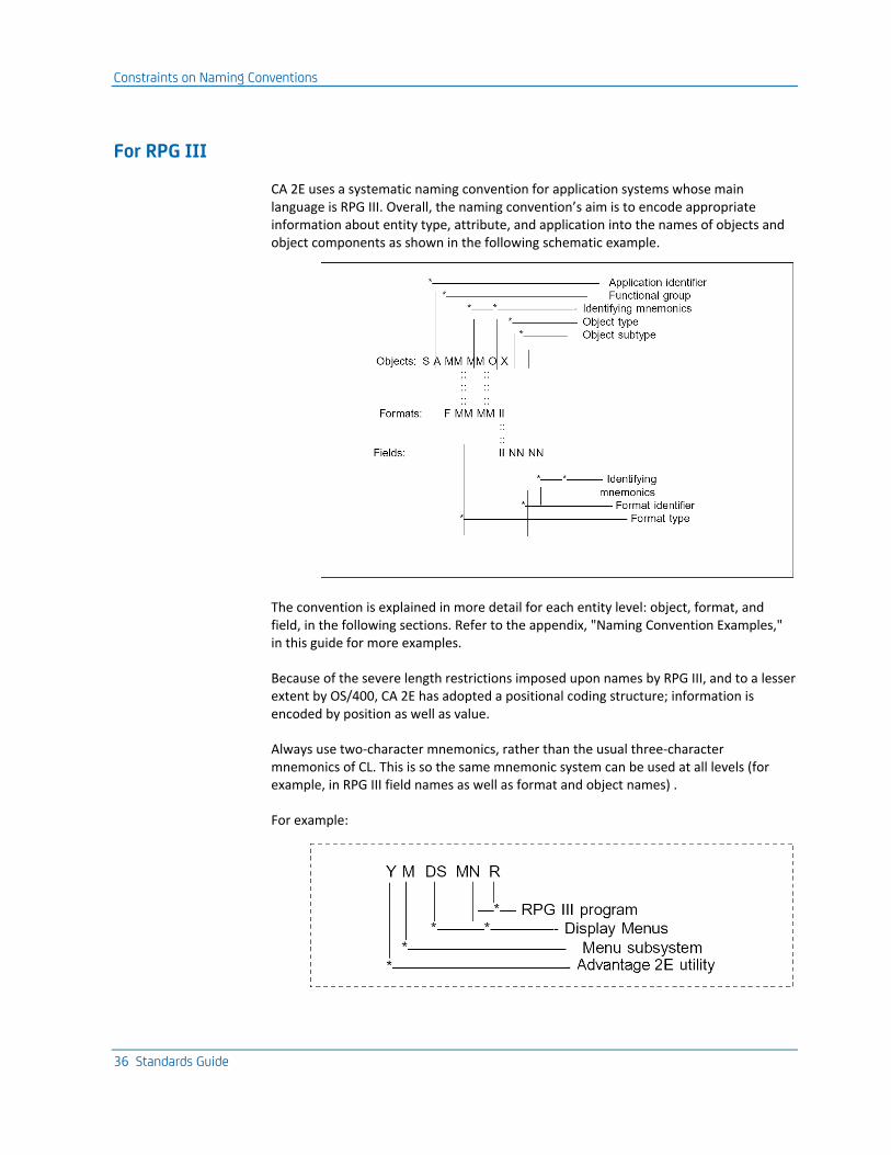
Constraints on Naming Conventions
36 Standards Guide
For RPG III
CA 2E uses a systematic naming convention for application systems whose main language is RPG III. Overall, the naming convention’s aim is to encode appropriate information about entity type, attribute, and application into the names of objects and object components as shown in the following schematic example.
The convention is explained in more detail for each entity level: object, format, and field, in the following sections. Refer to the appendix, "Naming Convention Examples," in this guide for more examples.
Because of the severe length restrictions imposed upon names by RPG III, and to a lesser extent by OS/400, CA 2E has adopted a positional coding structure; information is encoded by position as well as value.
Always use two-character mnemonics, rather than the usual three-character mnemonics of CL. This is so the same mnemonic system can be used at all levels (for example, in RPG III field names as well as format and object names) .
For example:
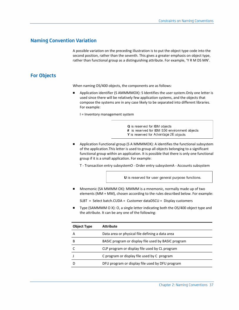
Constraints on Naming Conventions
Chapter 2: Naming Conventions 37
Naming Convention Variation
A possible variation on the preceding illustration is to put the object type code into the second position, rather than the seventh. This gives a greater emphasis on object type, rather than functional group as a distinguishing attribute. For example, ‘Y R M DS MN’.
For Objects
When naming OS/400 objects, the components are as follows:
■ Application identifier (S AMMMMOX): S Identifies the user system.Only one letter is used since there will be relatively few application systems, and the objects that compose the systems are in any case likely to be separated into different libraries. For example:
I = Inventory management system
■ Application Functional group (S A MMMMOX): A identifies the functional subsystem of the application.This letter is used to group all objects belonging to a significant functional group within an application. It is possible that there is only one functional group if it is a small application. For example:
T - Transaction entry subsystemO - Order entry subsystemA - Accounts subsystem
■ Mnemonic (SA MMMM OX): MMMM is a mnemonic, normally made up of two elements (MM + MM), chosen according to the rules described below. For example:
SLBT = Select batch.CUDA = Customer dataDSCU = Display customers
■ Type (SAMMMM O X): O, a single letter indicating both the OS/400 object type and the attribute. It can be any one of the following:
Object Type Attribute
A Data area or physical file defining a data area
B BASIC program or display file used by BASIC program
C CLP program or display file used by CL program
J C program or display file used by C program
D DFU program or display file used by DFU program
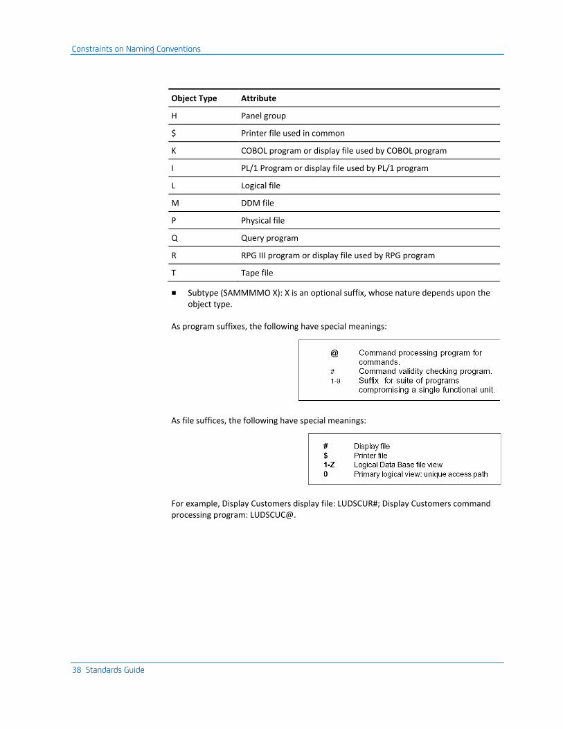
Constraints on Naming Conventions
38 Standards Guide
Object Type Attribute
H Panel group
$ Printer file used in common
K COBOL program or display file used by COBOL program
I PL/1 Program or display file used by PL/1 program
L Logical file
M DDM file
P Physical file
Q Query program
R RPG III program or display file used by RPG program
T Tape file
■ Subtype (SAMMMMO X): X is an optional suffix, whose nature depends upon the object type.
As program suffixes, the following have special meanings:
As file suffices, the following have special meanings:
For example, Display Customers display file: LUDSCUR#; Display Customers command processing program: LUDSCUC@.
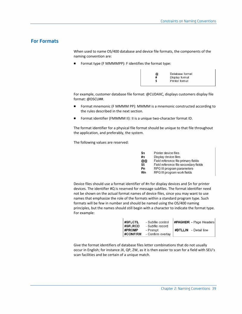
Constraints on Naming Conventions
Chapter 2: Naming Conventions 39
For Formats
When used to name OS/400 database and device file formats, the components of the naming convention are:
■ Format type (F MMMMPP): F identifies the format type:
For example, customer database file format: @CUDAXC, displays customers display file format: @DSCU##.
■ Format mnemonic (F MMMM PP): MMMM is a mnemonic constructed according to the rules described in the next section.
■ Format identifier (FMMMM II): II is a unique two-character format ID.
The format identifier for a physical file format should be unique to that file throughout the application, and preferably, the system.
The following values are reserved:
Device files should use a format identifier of #n for display devices and $n for printer devices. The identifier #Q is reserved for message subfiles. The format identifier need not be shown on the actual format names of device files, since you may want to use names that emphasize the role of the formats within a standard program type. Such formats will be few in number and should be named using the OS/400 naming principles, but the names should still begin with a character to indicate the format type. For example:
Give the format identifiers of database files letter combinations that do not usually occur in English; for instance JX, QP, ZW, as it is then easier to scan for a field with SEU’s scan facilities and be certain of a unique match.

Constraints on Naming Conventions
40 Standards Guide
For Fields
When naming OS/400 database and device file fields, the components are:
■ Format identifier (II NNNN): II is a unique two-character format identifier, as described previously.
■ Field mnemonic (PP NNNN): NNNN is a mnemonic that identifies the field
HLLs Other Than RPG III
If your application system is developed in a language other than RPG III, such as COBOL, C or PL/1, and there is no requirement to support RPG III programs, use a systematic naming convention that provides more meaningful names. This mainly amounts to being able to use three-character mnemonics as shown in the following example:
■ Database format and field names may be up to ten characters long.
■ Field names may be qualified by the format of the file from which they come. This means there is no need to include a format identifier as part of the field name.
The explanations of subcodes are the same as for the RPG III systematic convention given earlier.
Note: It is still useful to indicate the file type (database, display, printer) on the format. A common variation is to place the object type in either second position or last.
Mnemonics
Chapter 2: Naming Conventions 41
Mnemonics
A mnemonic is a symbolic abbreviation designed to be as memorable as possible; for instance DSP for Display, CHG for change.
An efficient mnemonic should be as short as possible, but also as clear as possible. The mnemonic system used for CL command names, in which mnemonics are generally three characters long and composed of the phonetically significant consonants, is a good compromise between the conflicting goals of brevity and recognizability.
CA 2E Mnemonic System
Due to the space limitations of RPG III, the CA 2E convention uses a standard mnemonic of only two letters, rather than the three characters of CL mnemonics.
Mnemonics should be made up of two-character components from a strictly limited vocabulary, for example, DT for date, CD for code, and TX for text. The same set of mnemonics should be used at all levels, for example, for objects, source members, format names, and fields.
Mnemonics will generally be used in pairs. Wherever possible, combine mnemonics as ‘verb+object’ or ‘adjective+noun’. For example, use DSRP for Display Report and MNCD for Menu Code.
A limited vocabulary of mnemonics should be used. This should be documented in the field dictionary for a system.
Certain mnemonics are reserved; for instance CD for code and TX for text. See the appendix, "EJB Option Runtime Example," in this guide, for a list of reserved mnemonics.
Formulate New Mnemonics
When creating new mnemonics:
■ Use a standard abbreviation if one exists, such as Co. or No.
■ Use the first letter in each syllable or of each compound word, for example MV for MoVe, SF for SubFile.
■ Make mnemonics unique and clear.
■ Use approximate synonyms to keep the number of mnemonics down. For instance, maintain, change, alter, and amend can all be described as change or CH.
■ Think of the CA 2E two-character mnemonic as an abbreviation of the three-character OS/400 mnemonic. Try to keep a one-to-one correspondence between two-and three-character mnemonics; for instance DS - DSP, CH - CHG, DA - DTA.
Mnemonics
42 Standards Guide
CA 2E and Mnemonics
The CA 2Eapplication generator has a facility to generate entity names automatically if the CA 2E YALCVNM model value has a value of *YES. Mnemonics are generated as follows:
■ The first mnemonic is generated arbitrarily to be unique within entity type.
■ The second mnemonic is derived from the entity types:
- Field data types (DTE - DT, CDE - CD, TXT -TX).
- File types (REF - RF, CPT - CP).
- Standard function types (EDTFIL - EF, DSPFIL - DF).
CA 2E Naming Convention Exceptions
The following OS/400 objects are exceptions to the CA 2E systematic naming convention:
■ Objects that may be referred to directly and frequently by the non-technical user:
- User profiles: User profile names should reflect the user’s role. If there are many users, a common prefix to indicate department and/or location may be useful. Reserve the prefix ‘Q’ for IBM profiles.
- Libraries: Library names should indicate the nature of the objects in the library. Reserve the prefix ‘Q’ IBM libraries (QSYS, QRPG, QRPLOBJ).
Advantages of CA 2E Naming Convention
Chapter 2: Naming Conventions 43
Advantages of CA 2E Naming Convention
Using the CA 2E naming convention has several advantages:
■ You can easily identify entities at any level:
- Names are made up from a restricted vocabulary of components, making it relatively easy to learn and remember.
- Strict use is made of positional information, so that a name can be clearly broken down into its components.
- Both object type and attribute are encoded in object names. This helps you to identify objects simply from their names.
- On lists, objects are arranged by functional group. Anomalies can be spotted.
- Fields can be related to formats, and formats related to files.
- Field names are uniquely qualified by format, so inadvertent file updates do not take place. Declaring an external file for use in an RPG III program automatically declares all the fields in the file to be available in the program. If more than one file contains a field of the same name, this can lead to undesirable effects in a program that accesses both of those files. For example, if you chain to a reference file while binding a transaction file record, and if both files contain a field of the same name, the field on the transaction file could be unintentionally updated with the field from the reference file. (Where field mapping is desired, fields can always be explicitly renamed.)
■ You can easily manipulate objects and source such as:
- Easy copying and inclusion from existing source.
- Easy manipulation of groups of entities by OS/400 and CA 2E 400 Toolkit utility commands. Since many commands work on "generic" names, this is of considerable practical significance.
■ You can benefit from greater productivity such as:
- You can create or analyze names with ease.
- You can include existing programs, source, and sections of source in new systems with greater ease.
- Programmers can understand unfamiliar code faster.
Enforcing A Naming Convention
44 Standards Guide
Enforcing A Naming Convention
The following techniques encourage the use of a naming convention:
■ Define all database fields in a field reference file. Designate one person who is well versed in your standards to be responsible for issuing field names in a field reference file.
■ Provide a standardized skeleton source as a basis to start coding.
■ Use tools such as CA 2E to generate names automatically, according to rules.
■ Consider providing an exit program for the programmer’s menu using the EXITPGM keyword on the OS/400 Display Programmer menu (DSPPGMMNU) command. This will check that the names given to source and object members satisfy your naming convention.
The following techniques ensure that appropriate names have been used; use the OS/400 Display library (DSPLIB) and Display object description (DSPOBJD) commands to obtain summary lists of object names.
Use the following CA 2E Toolkit documentation commands to check format and field names:
■ Document program references (YDOCPGMREF) with LSTBYFMT(*YES).
■ Document field references (YDOCFLDREF).
■ Document file summary (YDOCF).
■ Document program summary (YDOCPGM).
Chapter 3: IBM i General Design Standards 45
Chapter 3: IBM i General Design Standards
This chapter describes the principles of a good design method and what information is needed to start designing. It also provides suggestions for appropriate tools to use.
This section contains the following topics:
Design Methods (see page 46) Design Standards for User Interfaces (see page 48) Design Standards for Display Files (see page 56) Design Standards for Printer Files (see page 68) Design Standards for Menus (see page 71) Design Standards for Help Text (see page 75) Design Standards for Commands (see page 78) Design Standards for Database Files (see page 90) Design Standards for Programs (see page 102) Design Standards for Internationalization (see page 115)
Design Methods
46 Standards Guide
Design Methods
When you start to design your system, apply the following basic principles:
■ Use the computer as much as possible:
- Many aspects of the design process can be done automatically.
- You can use the computer to index and organize the design.
- You can repeatedly modify the design with minimum effort.
- You can use any existing designs.
- You can easily document the design.
- The results of the design can be carried through to implementation without re-keying.
- You can improve the quality.
- Use CASE tools, generators, and word processors wherever possible.
■ Present designs to the end user and reach agreement before programming starts. This is because:
- You must understand what the user wants; the only way you can verify user requirements is to restate your interpretation for verification.
- It is cost effective to incorporate changes before programming has begun.
Use prototyping and modeling tools wherever possible:
■ Use standards to reduce the complexity of the design problem. Omit features of appearance or performance from the specification that are covered by standards. This allows you to:
- use existing design work
- achieve more consistent user interface
- improve quality
Use design and generator tools that enforce standards:
■ Ensure that all systems have a consistent user interface—consistent internally within the application, with SAA CVA standards, and with the OS/400 system interfaces that will be common to all applications. This:
- reduces the amount of work required to specify a system
- simplifies the process of learning how to use the system
Use automatic layout tools:
■ Recognize that the design process is both iterative and experimental. It will require several passes to try out solutions, explore connections, and allow for user feedback.
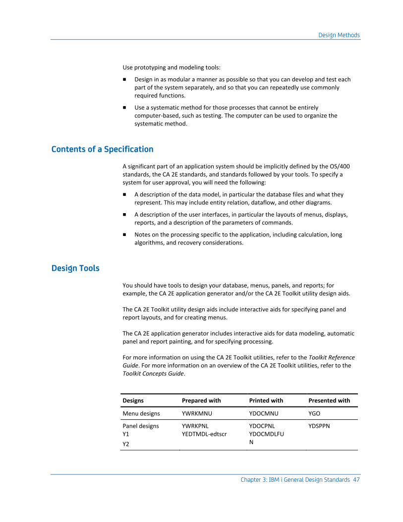
Design Methods
Chapter 3: IBM i General Design Standards 47
Use prototyping and modeling tools:
■ Design in as modular a manner as possible so that you can develop and test each part of the system separately, and so that you can repeatedly use commonly required functions.
■ Use a systematic method for those processes that cannot be entirely computer-based, such as testing. The computer can be used to organize the systematic method.
Contents of a Specification
A significant part of an application system should be implicitly defined by the OS/400 standards, the CA 2E standards, and standards followed by your tools. To specify a system for user approval, you will need the following:
■ A description of the data model, in particular the database files and what they represent. This may include entity relation, dataflow, and other diagrams.
■ A description of the user interfaces, in particular the layouts of menus, displays, reports, and a description of the parameters of commands.
■ Notes on the processing specific to the application, including calculation, long algorithms, and recovery considerations.
Design Tools
You should have tools to design your database, menus, panels, and reports; for example, the CA 2E application generator and/or the CA 2E Toolkit utility design aids.
The CA 2E Toolkit utility design aids include interactive aids for specifying panel and report layouts, and for creating menus.
The CA 2E application generator includes interactive aids for data modeling, automatic panel and report painting, and for specifying processing.
For more information on using the CA 2E Toolkit utilities, refer to the Toolkit Reference Guide. For more information on an overview of the CA 2E Toolkit utilities, refer to the Toolkit Concepts Guide.
Designs Prepared with Printed with Presented with
Menu designs YWRKMNU YDOCMNU YGO
Panel designs Y1
Y2
YWRKPNL YEDTMDL-edtscr
YDOCPNL YDOCMDLFU N
YDSPPN
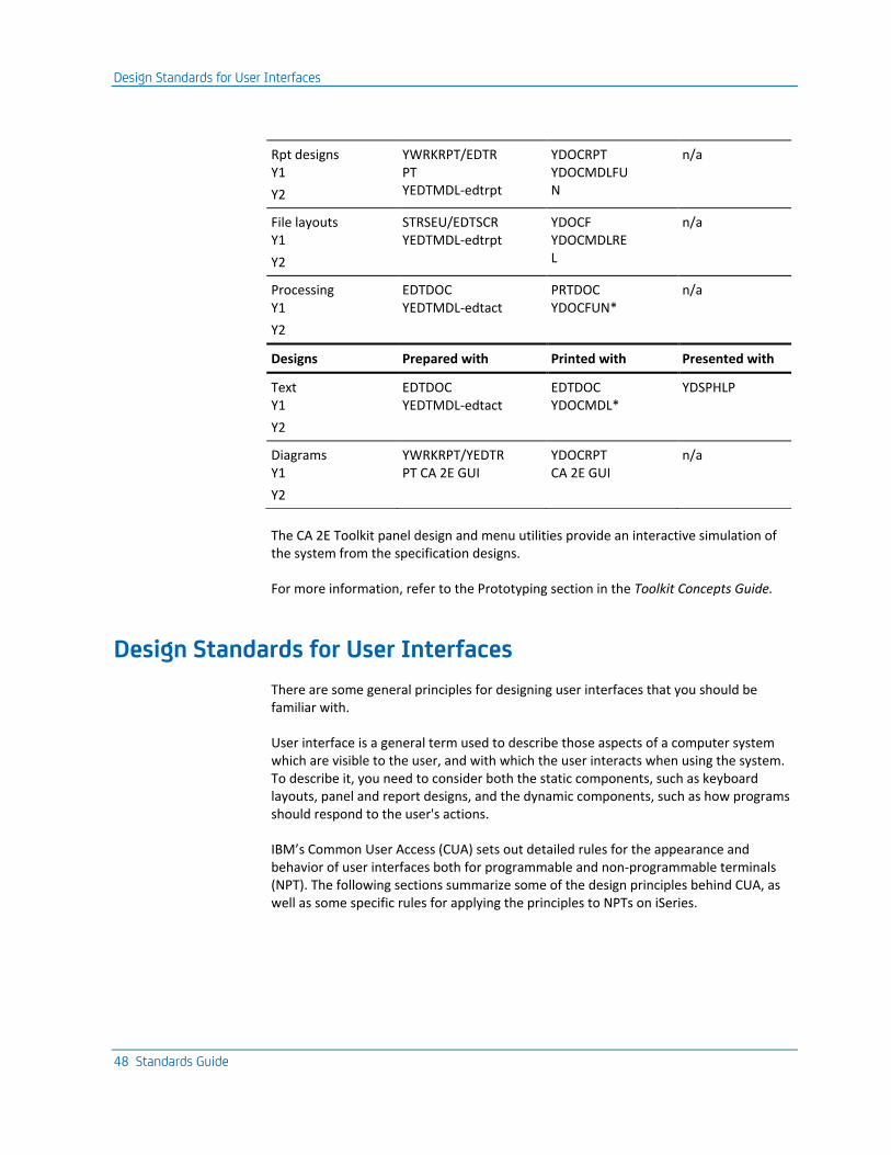
Design Standards for User Interfaces
48 Standards Guide
Rpt designs Y1
Y2
YWRKRPT/EDTR PT YEDTMDL-edtrpt
YDOCRPT YDOCMDLFU N
n/a
File layouts Y1
Y2
STRSEU/EDTSCR YEDTMDL-edtrpt
YDOCF YDOCMDLRE L
n/a
Processing Y1
Y2
EDTDOC YEDTMDL-edtact
PRTDOC YDOCFUN*
n/a
Designs Prepared with Printed with Presented with
Text Y1
Y2
EDTDOC YEDTMDL-edtact
EDTDOC YDOCMDL*
YDSPHLP
Diagrams Y1
Y2
YWRKRPT/YEDTR PT CA 2E GUI
YDOCRPT CA 2E GUI
n/a
The CA 2E Toolkit panel design and menu utilities provide an interactive simulation of the system from the specification designs.
For more information, refer to the Prototyping section in the Toolkit Concepts Guide.
Design Standards for User Interfaces
There are some general principles for designing user interfaces that you should be familiar with.
User interface is a general term used to describe those aspects of a computer system which are visible to the user, and with which the user interacts when using the system. To describe it, you need to consider both the static components, such as keyboard layouts, panel and report designs, and the dynamic components, such as how programs should respond to the user's actions.
IBM’s Common User Access (CUA) sets out detailed rules for the appearance and behavior of user interfaces both for programmable and non-programmable terminals (NPT). The following sections summarize some of the design principles behind CUA, as well as some specific rules for applying the principles to NPTs on iSeries.
Design Standards for User Interfaces
Chapter 3: IBM i General Design Standards 49
Ease of Use
To make your system easy to learn, consider the following:
■ Make the interfaces consistent. If your interfaces are consistent, then having learned to understand one interface, the user can understand related interfaces with little effort.
■ Choose objects that are intuitive to the user. This requires that you base the design on conceptual entities, which are familiar to the user.
■ Choose operations on the objects that are intuitive. For example, use create, change, delete, and work with. Use simple standard metaphors wherever possible.
■ Follow object-action principles. Generally, the user should choose an object, and then an action.
■ Allow backing out. It should be possible for the user to explore the system without serious consequences.
■ Provide feedback to reassure the user at every step.
■ Provide online help and search indices.
To make your system efficient to use, consider the following:
■ Use as simple of a design as possible.
■ Avoid the need for the user to recall information.
■ Avoid modes.
■ Provide basic and expert paths.
■ Make the most common path the default path.
■ Provide the system ready set up for use.
■ Only provide additional facilities on a demand basis.
Design Standards for User Interfaces
50 Standards Guide
Interface Consistency
IBM’s SAA divides consistency into three levels:
■ Physical—The actual layout of physical elements such as keyboards must be consistent. On the IBM midrange, physical consistency is for the most part taken care of by the hardware.
■ Syntactic—The use of interface elements must be consistent. For example, the presentation language (e.g. panel layout), the action language (e.g. F3=Exit) and CL syntax all need to be consistent. The SAA standards lay down rules for many aspects of interface consistency. The OS/400 Guide to Programming Application and Help Displays spells out how you should interpret these for the iSeries.
■ Semantic—The meaning of the interface elements and their interactions must be consistent. For instance, Exit should always take you back from a panel, without further update.
Note: Software productivity tools can play an important part in the successful implementation of consistent interface standards by suggesting, supplying, and even requiring, standardized design defaults.
Aspects of a User Interface
The CUA elements of IBM’s SAA includes standards for the following aspects of interface behavior. You should strive for consistency with these:
■ panel management
■ activity management
■ keyboard layout and usage
■ panel (display) interaction
■ selection action
■ messages and prompts
■ color and emphasis
■ help
■ national language support
■ terminology for end users
Design Standards for User Interfaces
Chapter 3: IBM i General Design Standards 51
Transfer of Learning
We have an innate ability to generalize from related cases—we use it to learn language. You apply this skill when using computer interfaces as well. For example, if you know there is a Delete Program command to delete programs, and you want to delete a new object type, say a ‘glob’, you will expect a Delete Glob command to remove it.
Try to choose operations that have intuitive metaphors. Most operations can be presented in terms of a relatively small number of primitive operations, for example, creating, changing, deleting, moving, merging, and splitting, which are intuitive to a user.
Modal Behavior
Users often need to switch between tasks. You should try to avoid constraining what a user can do next at any point. In particular, avoid ‘modes’. A program exhibits modal behavior if it restricts the user to a limited range of responses determined by what has taken place previously. A mode requires the user to carry out particular actions in steps to exit from the mode. Although it is almost impossible to avoid modes on the iSeries because of the hierarchical call-invocation model, you should still try to minimize their effect. Use flat hierarchies, enable the command line, and allow backing out.
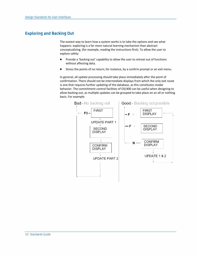
Design Standards for User Interfaces
52 Standards Guide
Exploring and Backing Out
The easiest way to learn how a system works is to take the options and see what happens: exploring is a far more natural learning mechanism than abstract conceptualizing, (for example, reading the instructions first). To allow the user to explore safely:
■ Provide a ‘backing out’ capability to allow the user to retreat out of functions without affecting data.
■ Stress the points of no return; for instance, by a confirm prompt or an exit menu.
In general, all update processing should take place immediately after the point of confirmation. There should not be intermediate displays from which the only exit route is one that requires further updating of the database, as this constitutes modal behavior. The commitment control facilities of OS/400 can be useful when designing to allow backing out, as multiple updates can be grouped to take place on an all or nothing basis. For example:
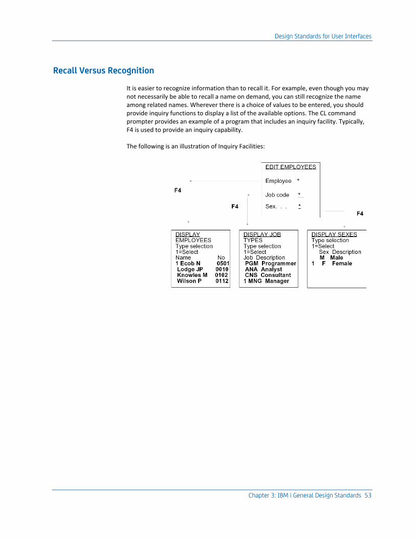
Design Standards for User Interfaces
Chapter 3: IBM i General Design Standards 53
Recall Versus Recognition
It is easier to recognize information than to recall it. For example, even though you may not necessarily be able to recall a name on demand, you can still recognize the name among related names. Wherever there is a choice of values to be entered, you should provide inquiry functions to display a list of the available options. The CL command prompter provides an example of a program that includes an inquiry facility. Typically, F4 is used to provide an inquiry capability.
The following is an illustration of Inquiry Facilities:
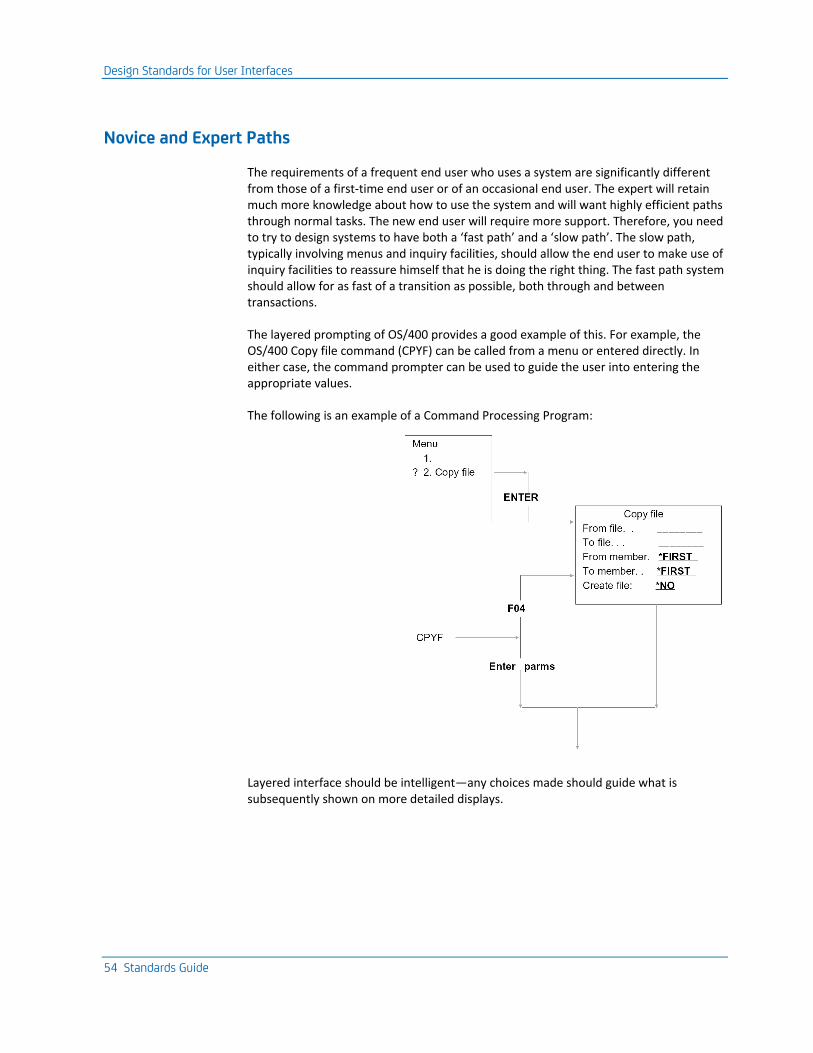
Design Standards for User Interfaces
54 Standards Guide
Novice and Expert Paths
The requirements of a frequent end user who uses a system are significantly different from those of a first-time end user or of an occasional end user. The expert will retain much more knowledge about how to use the system and will want highly efficient paths through normal tasks. The new end user will require more support. Therefore, you need to try to design systems to have both a ‘fast path’ and a ‘slow path’. The slow path, typically involving menus and inquiry facilities, should allow the end user to make use of inquiry facilities to reassure himself that he is doing the right thing. The fast path system should allow for as fast of a transition as possible, both through and between transactions.
The layered prompting of OS/400 provides a good example of this. For example, the OS/400 Copy file command (CPYF) can be called from a menu or entered directly. In either case, the command prompter can be used to guide the user into entering the appropriate values.
The following is an example of a Command Processing Program:
Layered interface should be intelligent—any choices made should guide what is subsequently shown on more detailed displays.
Design Standards for User Interfaces
Chapter 3: IBM i General Design Standards 55
Contextual Information
It is difficult to keep your attention focused for long periods of time. When using a complex system, end users may lose track of where they are, especially if they suffer interruptions. You should provide information to remind users where they are and what they are doing.
This should be standardized and in the same place (for example, titles and instruction areas on a panel) so that it can be ignored unless needed. The most useful information to establish a context for is generally information about any immediately related entities; for instance, the customer for whom an order is raised or the department to which an employee belongs. The presence of such information makes it possible for the user to establish what he is doing at a glance—especially when returning after an interruption. Connections between panels should follow the structure of the data so as to facilitate this.
Shipped Systems
Most people do not learn by studying abstract principles. Rather, they build up their knowledge gradually. The idea of a shipped system can be used to make learning to use a system easier. A shipped system provides a workable environment and sensible defaults for control values, so that a new user can immediately do useful work. OS/400 themselves provide good examples of this—the shipped system contains subsystems and output queues, which are ready for immediate use, but which may be subsequently modified if desired.
Design Standards for Display Files
56 Standards Guide
iSeries User Interface Implementation Components
User interfaces for the native iSeries are made up of the following components:
■ Commands—The OS/400 Command Language (CL) provides a user interface that is rigorously consistent, both in appearance and in behavior. It is worth using the CL command definition language wherever possible. When defining commands, you should adhere strictly to the CL conventions. Some of these are discussed in the sections on designing and coding commands, later in this guide. However, commands are not suitable for all occasions; displays are also needed.
■ Display files—Display files are used to define the panels the user sees. They should be specified as external files using DDS. When defining display files, it is important to use a consistent layout, give standard weightings to the display field attributes, and handle error reporting in a consistent manner. On iSeries, control features of the programs driving the display, such as command key usage, cursor movement, and prompting for confirmation, should also be standardized to follow the SAA CUA guidelines.
Note: For more information, refer to IBM's Defining iSeries (AS/400) Compatible Displays Using DDS Specifications.
■ Help text—Help text is written using UIM help. Examples of how to do this are given in the IBM publication, The Guide to Programming Application Panel and Help Displays.
■ Print files—Print files should be specified as external files using DDS. The important considerations are to use a consistent layout and to provide reference information to indicate how, when, and by whom the report was produced.
Design Standards for Display Files
Design standards for display files are described in this section. This section also provides general points for panel design. Detailed rules for panel design are given in the iSeries (AS/400) Guide to Programming Panels and Help Displays.
For the IBM Midrange
It is important that all panels in an application system are designed to the same standards. This makes panels much easier to understand, user education much simpler, and improves appearance.
On iSeries, the standards set out by the IBM SAA Common User Interface should be followed. These are described in the Guide to Programming Application and Help Displays and are exemplified by the OS/400 system displays.
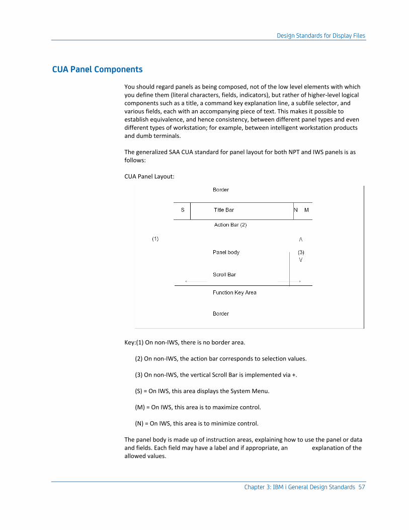
Design Standards for Display Files
Chapter 3: IBM i General Design Standards 57
CUA Panel Components
You should regard panels as being composed, not of the low level elements with which you define them (literal characters, fields, indicators), but rather of higher-level logical components such as a title, a command key explanation line, a subfile selector, and various fields, each with an accompanying piece of text. This makes it possible to establish equivalence, and hence consistency, between different panel types and even different types of workstation; for example, between intelligent workstation products and dumb terminals.
The generalized SAA CUA standard for panel layout for both NPT and IWS panels is as follows:
CUA Panel Layout:
Key:(1) On non-IWS, there is no border area.
(2) On non-IWS, the action bar corresponds to selection values.
(3) On non-IWS, the vertical Scroll Bar is implemented via +.
(S) = On IWS, this area displays the System Menu.
(M) = On IWS, this area is to maximize control.
(N) = On IWS, this area is to minimize control.
The panel body is made up of instruction areas, explaining how to use the panel or data and fields. Each field may have a label and if appropriate, an explanation of the allowed values.
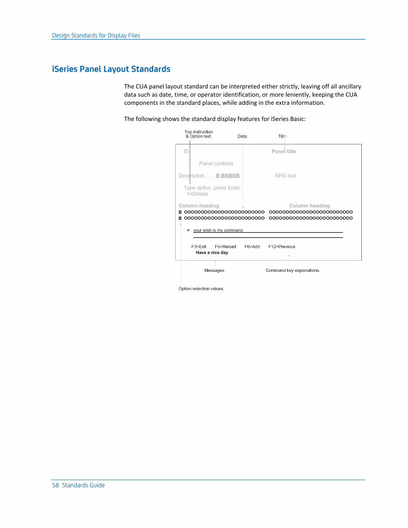
Design Standards for Display Files
58 Standards Guide
iSeries Panel Layout Standards
The CUA panel layout standard can be interpreted either strictly, leaving off all ancillary data such as date, time, or operator identification, or more leniently, keeping the CUA components in the standard places, while adding in the extra information.
The following shows the standard display features for iSeries Basic:
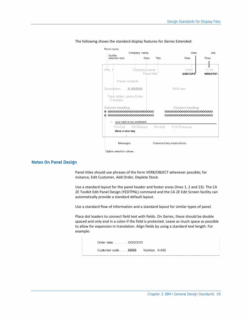
Design Standards for Display Files
Chapter 3: IBM i General Design Standards 59
The following shows the standard display features for iSeries Extended:
Notes On Panel Design
Panel titles should use phrases of the form VERB/OBJECT whenever possible; for instance, Edit Customer, Add Order, Deplete Stock.
Use a standard layout for the panel header and footer areas (lines 1, 2 and 23). The CA 2E Toolkit Edit Panel Design (YEDTPNL) command and the CA 2E Edit Screen facility can automatically provide a standard default layout.
Use a standard flow of information and a standard layout for similar types of panel.
Place dot leaders to connect field text with fields. On iSeries, these should be double spaced and only end in a colon if the field is protected. Leave as much space as possible to allow for expansion in translation. Align fields by using a standard text length. For example:
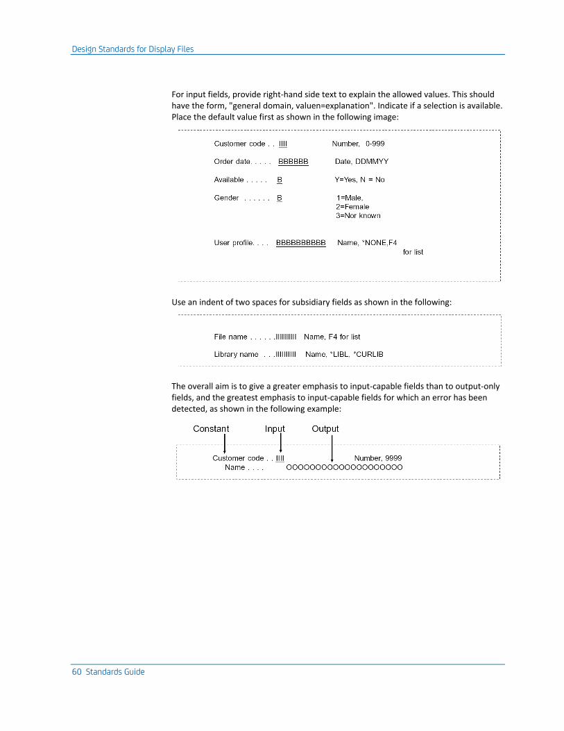
Design Standards for Display Files
60 Standards Guide
For input fields, provide right-hand side text to explain the allowed values. This should have the form, "general domain, valuen=explanation". Indicate if a selection is available. Place the default value first as shown in the following image:
Use an indent of two spaces for subsidiary fields as shown in the following:
The overall aim is to give a greater emphasis to input-capable fields than to output-only fields, and the greatest emphasis to input-capable fields for which an error has been detected, as shown in the following example:
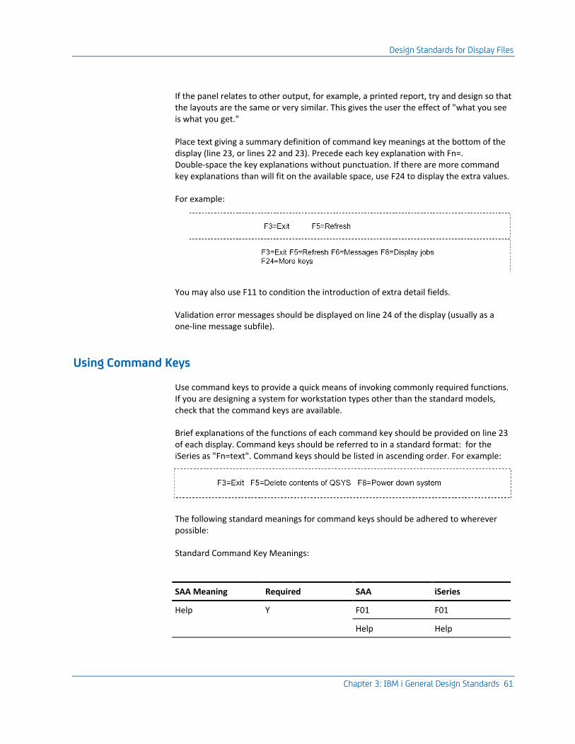
Design Standards for Display Files
Chapter 3: IBM i General Design Standards 61
If the panel relates to other output, for example, a printed report, try and design so that the layouts are the same or very similar. This gives the user the effect of "what you see is what you get."
Place text giving a summary definition of command key meanings at the bottom of the display (line 23, or lines 22 and 23). Precede each key explanation with Fn=. Double-space the key explanations without punctuation. If there are more command key explanations than will fit on the available space, use F24 to display the extra values.
For example:
You may also use F11 to condition the introduction of extra detail fields.
Validation error messages should be displayed on line 24 of the display (usually as a one-line message subfile).
Using Command Keys
Use command keys to provide a quick means of invoking commonly required functions. If you are designing a system for workstation types other than the standard models, check that the command keys are available.
Brief explanations of the functions of each command key should be provided on line 23 of each display. Command keys should be referred to in a standard format: for the iSeries as "Fn=text". Command keys should be listed in ascending order. For example:
The following standard meanings for command keys should be adhered to wherever possible:
Standard Command Key Meanings:
SAA Meaning Required SAA iSeries
Help Y F01 F01
Help Help
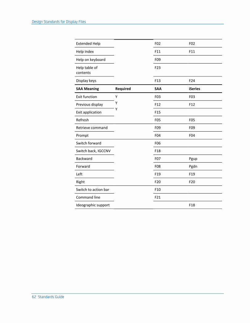
Design Standards for Display Files
62 Standards Guide
Extended Help F02 F02
Help index F11 F11
Help on keyboard F09
Help table of contents
F23
Display keys F13 F24
SAA Meaning Required SAA iSeries
Exit function Y
Y
Y
F03 F03
Previous display F12 F12
Exit application F15
Refresh F05 F05
Retrieve command F09 F09
Prompt F04 F04
Switch forward F06
Switch back, IGCCNV F18
Backward F07 Pgup
Forward F08 Pgdn
Left F19 F19
Right F20 F20
Switch to action bar F10
Command line F21
Ideographic support F18
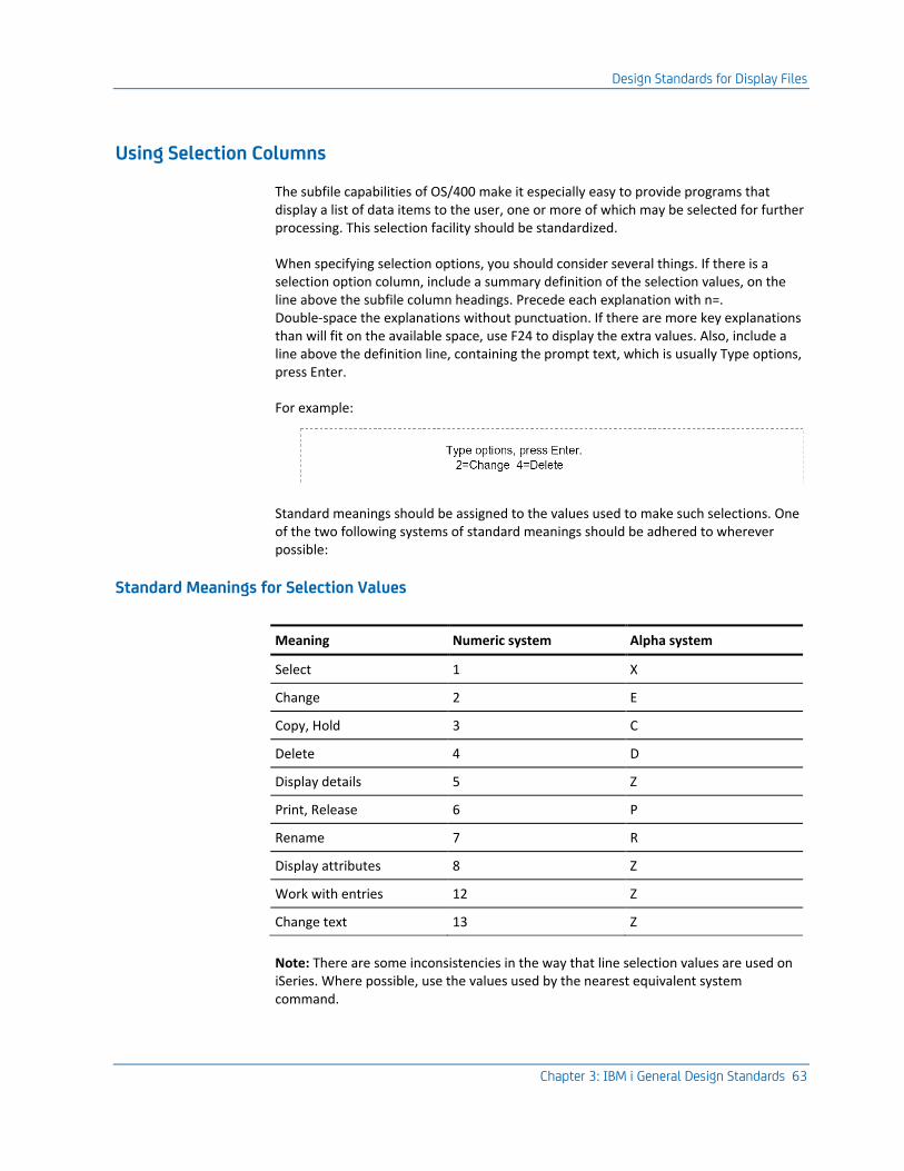
Design Standards for Display Files
Chapter 3: IBM i General Design Standards 63
Using Selection Columns
The subfile capabilities of OS/400 make it especially easy to provide programs that display a list of data items to the user, one or more of which may be selected for further processing. This selection facility should be standardized.
When specifying selection options, you should consider several things. If there is a selection option column, include a summary definition of the selection values, on the line above the subfile column headings. Precede each explanation with n=. Double-space the explanations without punctuation. If there are more key explanations than will fit on the available space, use F24 to display the extra values. Also, include a line above the definition line, containing the prompt text, which is usually Type options, press Enter.
For example:
Standard meanings should be assigned to the values used to make such selections. One of the two following systems of standard meanings should be adhered to wherever possible:
Standard Meanings for Selection Values
Meaning Numeric system Alpha system
Select 1 X
Change 2 E
Copy, Hold 3 C
Delete 4 D
Display details 5 Z
Print, Release 6 P
Rename 7 R
Display attributes 8 Z
Work with entries 12 Z
Change text 13 Z
Note: There are some inconsistencies in the way that line selection values are used on iSeries. Where possible, use the values used by the nearest equivalent system command.
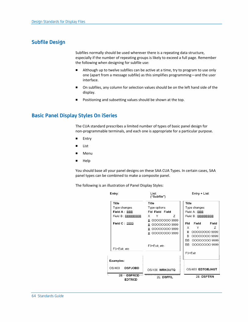
Design Standards for Display Files
64 Standards Guide
Subfile Design
Subfiles normally should be used wherever there is a repeating data structure, especially if the number of repeating groups is likely to exceed a full page. Remember the following when designing for subfile use:
■ Although up to twelve subfiles can be active at a time, try to program to use only one (apart from a message subfile) as this simplifies programming—and the user interface.
■ On subfiles, any column for selection values should be on the left hand side of the display.
■ Positioning and subsetting values should be shown at the top.
Basic Panel Display Styles On iSeries
The CUA standard prescribes a limited number of types of basic panel design for non-programmable terminals, and each one is appropriate for a particular purpose.
■ Entry
■ List
■ Menu
■ Help
You should base all your panel designs on these SAA CUA Types. In certain cases, SAA panel types can be combined to make a composite panel.
The following is an illustration of Panel Display Styles:
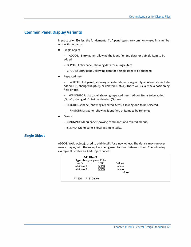
Design Standards for Display Files
Chapter 3: IBM i General Design Standards 65
Common Panel Display Variants
In practice on iSeries, the fundamental CUA panel types are commonly used in a number of specific variants:
■ Single object
- ADDOBJ: Entry panel, allowing the identifier and data for a single item to be added.
- DSPOBJ: Entry panel, showing data for a single item.
- CHGOBJ: Entry panel, allowing data for a single item to be changed.
■ Repeated item
- WRKOBJ: List panel, showing repeated items of a given type. Allows items to be added (F6), changed (Opt=2), or deleted (Opt=4). There will usually be a positioning field on top.
- WRKOBJTOP: List panel, showing repeated items. Allows items to be added (Opt=1), changed (Opt=2) or deleted (Opt=4).
- SLTOBJ: List panel, showing repeated items, allowing one to be selected.
- RNMOBJ: List panel, showing identifiers of items to be renamed.
■ Menus
- CMDMNU: Menu panel showing commands and related menus.
- TSKMNU: Menu panel showing simple tasks.
Single Object
ADDOBJ (Add object). Used to add details for a new object. The details may run over several pages, with the rollup keys being used to scroll between them. The following example illustrates an Add Object panel.
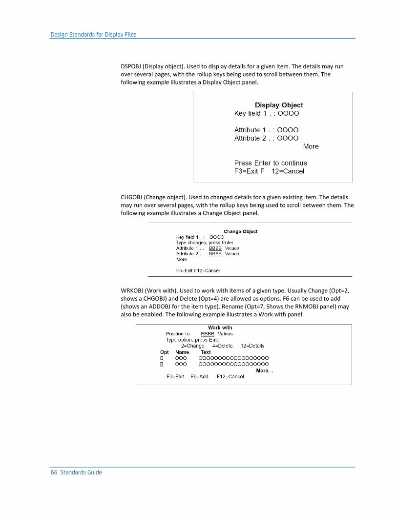
Design Standards for Display Files
66 Standards Guide
DSPOBJ (Display object). Used to display details for a given item. The details may run over several pages, with the rollup keys being used to scroll between them. The following example illustrates a Display Object panel.
CHGOBJ (Change object). Used to changed details for a given existing item. The details may run over several pages, with the rollup keys being used to scroll between them. The following example illustrates a Change Object panel.
WRKOBJ (Work with). Used to work with items of a given type. Usually Change (Opt=2, shows a CHGOBJ) and Delete (Opt=4) are allowed as options. F6 can be used to add (shows an ADDOBJ for the item type). Rename (Opt=7, Shows the RNMOBJ panel) may also be enabled. The following example illustrates a Work with panel.
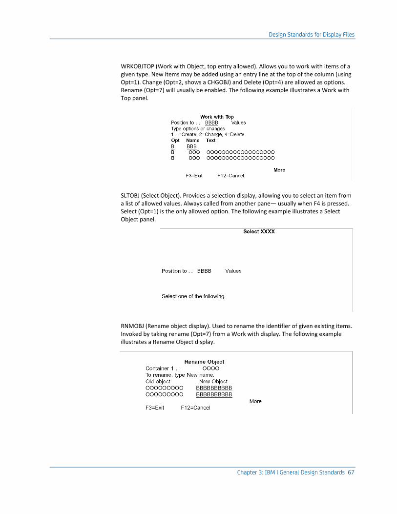
Design Standards for Display Files
Chapter 3: IBM i General Design Standards 67
WRKOBJTOP (Work with Object, top entry allowed). Allows you to work with items of a given type. New items may be added using an entry line at the top of the column (using Opt=1). Change (Opt=2, shows a CHGOBJ) and Delete (Opt=4) are allowed as options. Rename (Opt=7) will usually be enabled. The following example illustrates a Work with Top panel.
SLTOBJ (Select Object). Provides a selection display, allowing you to select an item from a list of allowed values. Always called from another pane— usually when F4 is pressed. Select (Opt=1) is the only allowed option. The following example illustrates a Select Object panel.
RNMOBJ (Rename object display). Used to rename the identifier of given existing items. Invoked by taking rename (Opt=7) from a Work with display. The following example illustrates a Rename Object display.
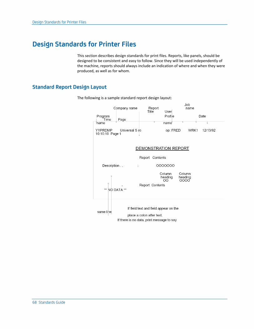
Design Standards for Printer Files
68 Standards Guide
Design Standards for Printer Files
This section describes design standards for print files. Reports, like panels, should be designed to be consistent and easy to follow. Since they will be used independently of the machine, reports should always include an indication of where and when they were produced, as well as for whom.
Standard Report Design Layout
The following is a sample standard report design layout:
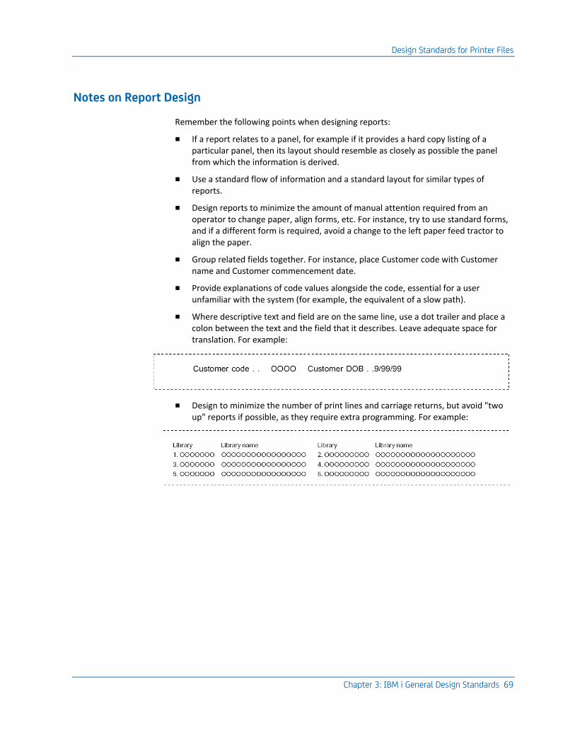
Design Standards for Printer Files
Chapter 3: IBM i General Design Standards 69
Notes on Report Design
Remember the following points when designing reports:
■ If a report relates to a panel, for example if it provides a hard copy listing of a particular panel, then its layout should resemble as closely as possible the panel from which the information is derived.
■ Use a standard flow of information and a standard layout for similar types of reports.
■ Design reports to minimize the amount of manual attention required from an operator to change paper, align forms, etc. For instance, try to use standard forms, and if a different form is required, avoid a change to the left paper feed tractor to align the paper.
■ Group related fields together. For instance, place Customer code with Customer name and Customer commencement date.
■ Provide explanations of code values alongside the code, essential for a user unfamiliar with the system (for example, the equivalent of a slow path).
■ Where descriptive text and field are on the same line, use a dot trailer and place a colon between the text and the field that it describes. Leave adequate space for translation. For example:
■ Design to minimize the number of print lines and carriage returns, but avoid "two up" reports if possible, as they require extra programming. For example:
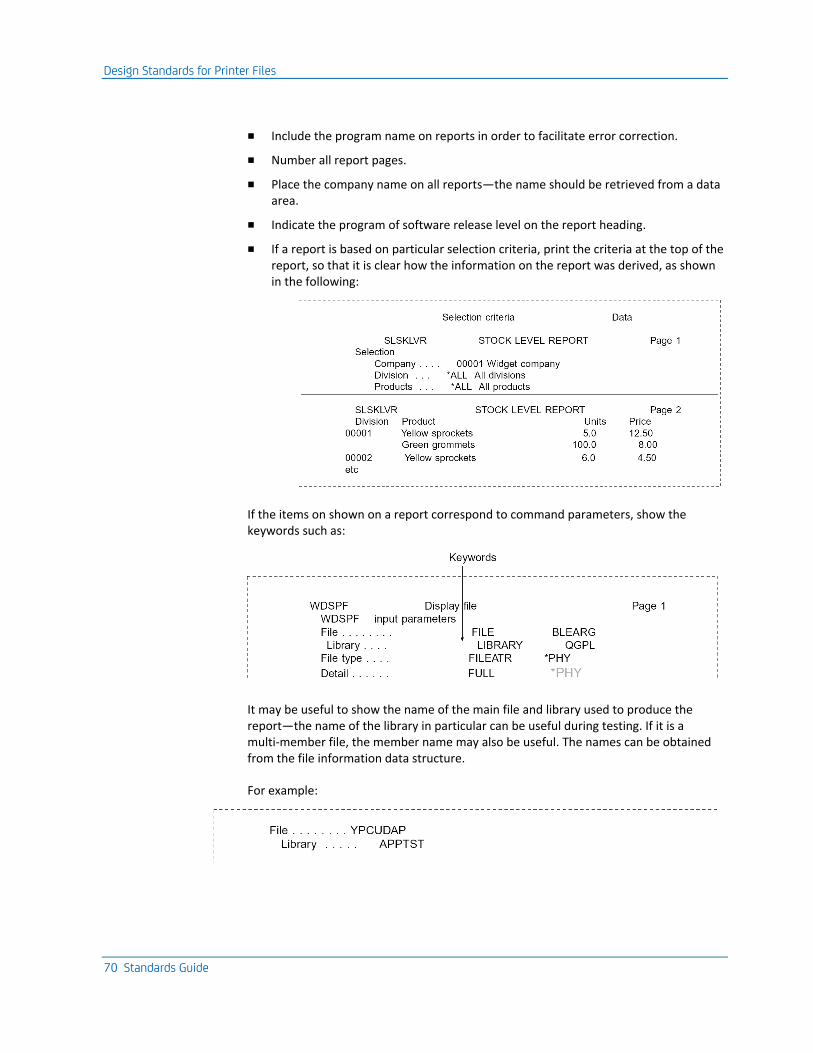
Design Standards for Printer Files
70 Standards Guide
■ Include the program name on reports in order to facilitate error correction.
■ Number all report pages.
■ Place the company name on all reports—the name should be retrieved from a data area.
■ Indicate the program of software release level on the report heading.
■ If a report is based on particular selection criteria, print the criteria at the top of the report, so that it is clear how the information on the report was derived, as shown in the following:
If the items on shown on a report correspond to command parameters, show the keywords such as:
It may be useful to show the name of the main file and library used to produce the report—the name of the library in particular can be useful during testing. If it is a multi-member file, the member name may also be useful. The names can be obtained from the file information data structure.
For example:
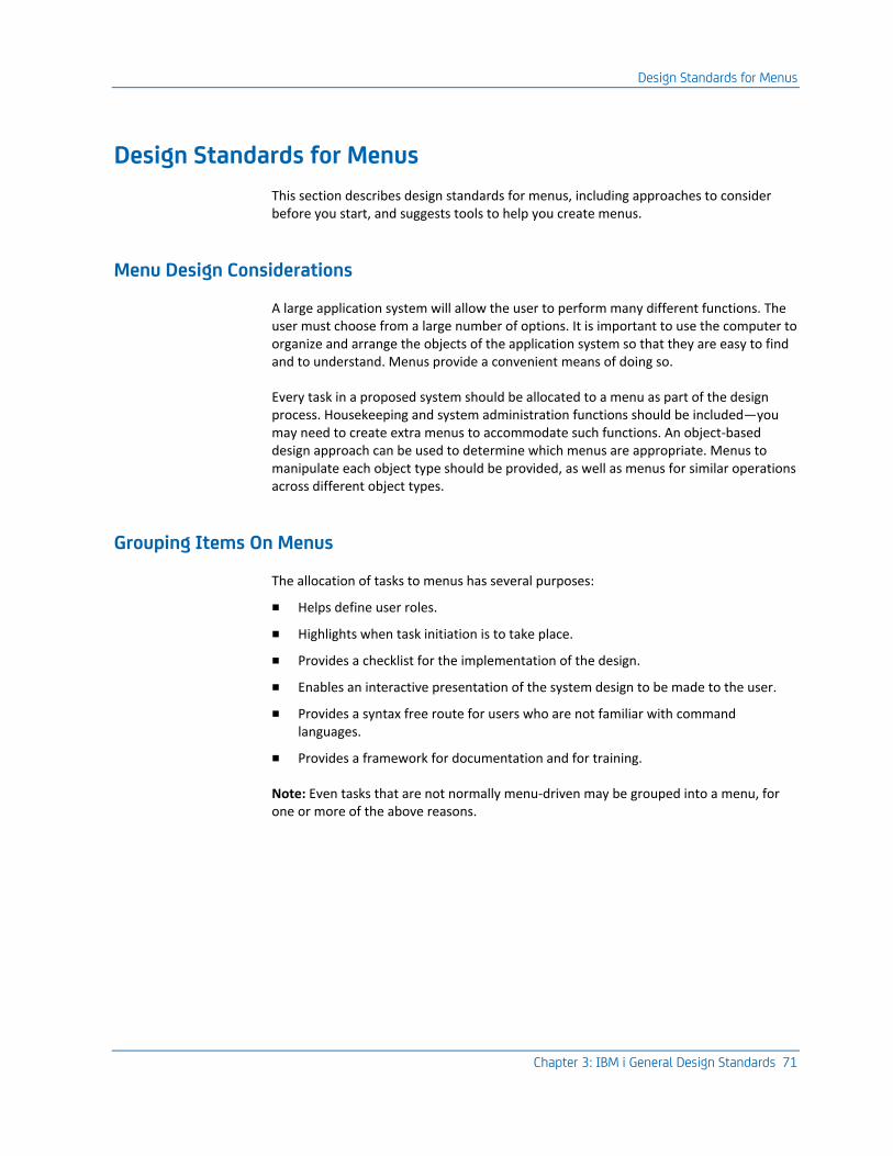
Design Standards for Menus
Chapter 3: IBM i General Design Standards 71
Design Standards for Menus
This section describes design standards for menus, including approaches to consider before you start, and suggests tools to help you create menus.
Menu Design Considerations
A large application system will allow the user to perform many different functions. The user must choose from a large number of options. It is important to use the computer to organize and arrange the objects of the application system so that they are easy to find and to understand. Menus provide a convenient means of doing so.
Every task in a proposed system should be allocated to a menu as part of the design process. Housekeeping and system administration functions should be included—you may need to create extra menus to accommodate such functions. An object-based design approach can be used to determine which menus are appropriate. Menus to manipulate each object type should be provided, as well as menus for similar operations across different object types.
Grouping Items On Menus
The allocation of tasks to menus has several purposes:
■ Helps define user roles.
■ Highlights when task initiation is to take place.
■ Provides a checklist for the implementation of the design.
■ Enables an interactive presentation of the system design to be made to the user.
■ Provides a syntax free route for users who are not familiar with command languages.
■ Provides a framework for documentation and for training.
Note: Even tasks that are not normally menu-driven may be grouped into a menu, for one or more of the above reasons.
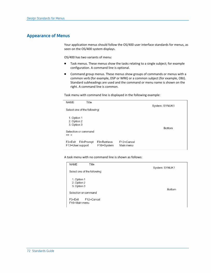
Design Standards for Menus
72 Standards Guide
Appearance of Menus
Your application menus should follow the OS/400 user interface standards for menus, as seen on the OS/400 system displays.
OS/400 has two variants of menu:
■ Task menus. These menus show the tasks relating to a single subject; for example configuration. A command line is optional.
■ Command group menus. These menus show groups of commands or menus with a common verb (for example, DSP or WRK) or a common subject (for example, OBJ). Standard subheadings are used and the command or menu name is shown on the right. A command line is common.
Task menu with command line is displayed in the following example:
A task menu with no command line is shown as follows:
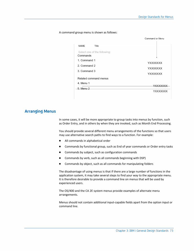
Design Standards for Menus
Chapter 3: IBM i General Design Standards 73
A command group menu is shown as follows:
Arranging Menus
In some cases, it will be more appropriate to group tasks into menus by function, such as Order Entry, and in others by when they are invoked, such as Month End Processing.
You should provide several different menu arrangements of the functions so that users may use alternative search paths to find ways to a function. For example:
■ All commands in alphabetical order
■ Commands by functional group, such as End of year commands or Order entry tasks
■ Commands by subject, such as configuration commands
■ Commands by verb, such as all commands beginning with DSP)
■ Commands by object, such as all commands for manipulating folders
The disadvantage of using menus is that if there are a large number of functions in the application system, it may take several steps to find your way to the appropriate menu. It is therefore desirable to provide a command line on menus that will be used by experienced users.
The OS/400 and the CA 2E system menus provide examples of alternate menu arrangements.
Menus should not contain additional input-capable fields apart from the option input or command line.
Design Standards for Menus
74 Standards Guide
Order of options
On command group menus, options should be arranged in alphabetical order by command.
On task menus, options should be placed on menus in the order in which they are likely to be used. In particular, place options to manipulate an entity in a sequence that follows the life cycle of the entity. For example, of the following two possible arrangements, the second is better than the first:
Menu Names
Menu names are likely to be used by the end user, so they should be designed to be as meaningful as possible. You need to ensure however, that the names do not coincide with those of OS/400 system menus, so we recommend that you use a single-level prefix.
Names for command group menus should have the form: application prefix + CMD + mnemonic; for example, YCMDDSP for a menu of all display (DSP) commands.
Names for task menus should be single nouns, preceded by an application prefix; for example, YDOCUMENT, YDEVICE. Longer terms can be abbreviated using OS/400 style mnemonics; for example STKLVL: stock levels, ORDENT: Order entry.
Tools for Creating Menus
Menus can be created with the CA 2E Toolkit Work with Menu (YWRKMNU) utility. The menu utilities provide a standard layout.
The Toolkit menu display program can provide a number of commonly required facilities. For example, it can provide a confirm prompt to check that the user really wishes to take an option, it can display Help text associated with an option, and can submit a request to run in batch rather than interactively.

Design Standards for Help Text
Chapter 3: IBM i General Design Standards 75
Design Standards for Help Text
This section describes design standards for Help text and includes a brief discussion of reasons for providing Help text. It details Help Text standards for panels, commands, and menus. Information on search indexes is also provided.
Help Text Design Considerations
It is important to provide Help text for all panels, menus, and commands of an application in order to make the applications easy to use.
Because Help text is generally used mostly by new or inexperienced users, it is important that it is itself easy to use.
Use a standardized structure that can be related to the panel that it explains. Follow the OS/400 standards.
Use simple language. Avoid jargon, and explain what the panel and its fields are for, rather than how the program internals work. Make sure that terminology on panels matches with that in the Help text.
Follow UIS standards for the use of emphasis.
Use boldface type for headings and allowed values. Use underline for default values and for hypertext links (automatic) extended headings. UIM will do this automatically if you use the correct tags. Do not make an excessive use of emphasis, as it is distracting to the reader.
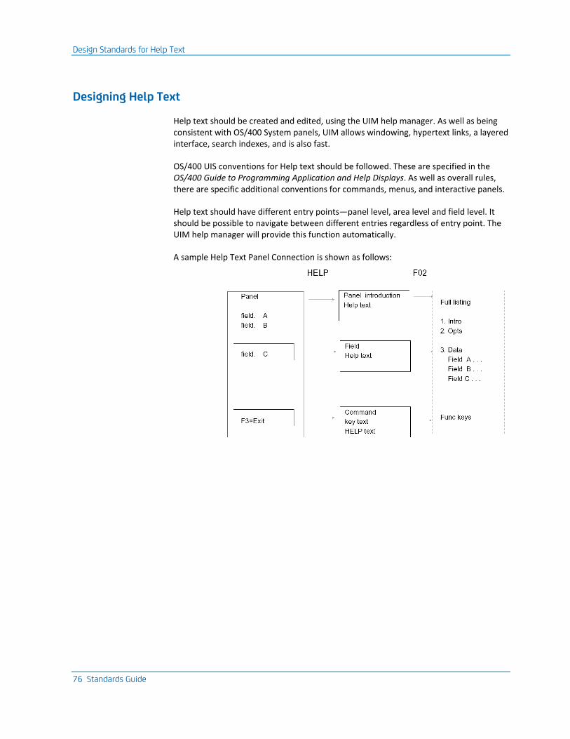
Design Standards for Help Text
76 Standards Guide
Designing Help Text
Help text should be created and edited, using the UIM help manager. As well as being consistent with OS/400 System panels, UIM allows windowing, hypertext links, a layered interface, search indexes, and is also fast.
OS/400 UIS conventions for Help text should be followed. These are specified in the OS/400 Guide to Programming Application and Help Displays. As well as overall rules, there are specific additional conventions for commands, menus, and interactive panels.
Help text should have different entry points—panel level, area level and field level. It should be possible to navigate between different entries regardless of entry point. The UIM help manager will provide this function automatically.
A sample Help Text Panel Connection is shown as follows:
Design Standards for Help Text
Chapter 3: IBM i General Design Standards 77
Panel Help Text
All interactive programs should have operating instructions that should be displayed when the HELP key is pressed. The help text should follow the UIS standards used on system panels and should contain:
1. Function: A synopsis of the purpose the program; for example, what the program does for the user, or for the application system. This may contain hypertext links to related objects.
2. Option values: A brief description of any line selection functions (for example, 4=Delete).
3. Field descriptions: A description of all data items, including all allowed values and any input validation rules.
4. Notes and examples: Any special notes or additional comments that may be useful to the user.
5. Function keys: A short description of any command key functions (for example, F3=Exit).
Command Help Text
Help text should be provided for each command. The help text should follow the UIS standards used on system panels and should contain:
1. Function: A synopsis of the purpose the command; for example, what the program does for the user, or for the application system. This may contain hypertext links to related objects.
2. Parameter descriptions: each parameter should be described, along with any allowed values.
Menu Help Text
Help text should be provided for each menu. The Help text should follow the UIS standards used on system menus and should contain:
1. Function: A summary of the subject covered by the menu.
2. How to use the menu: A standard paragraph on how to use a menu should be provided
3. Option descriptions: Each option should be described, under a heading, giving the option number. The introduction help group for the option object can be used. For example, if the option is a command, use the overview help text for the command.
4. Function keys: A short description of any command key functions (for example, F3=Exit).
Design Standards for Commands
78 Standards Guide
Search Indexes
Help panels assist users who already know how and why to start a command or program. Search indexes provide users with a way of finding out how to do something in the first place. You should provide a search index for your application, which should include
■ Entries for each command and each menu
■ "How" entries for commonly required operations
■ "What" entries for fundamental concepts—the objects and entities on the system
■ OS/400 standard root keywords, for example How, What, Novice
■ Entries for common synonyms, for example, "create, make, build"
■ An entry on how to use the search index itself. You can reference the help group of the system menu
Design Standards for Commands
This section describes standards for designing CL commands. It lists reasons for using commands, and details standards to use when specifying names, parameter key words, values, and prompt text for commands.
Design Standards for Commands
Chapter 3: IBM i General Design Standards 79
Why Use Commands?
Most user application systems will be menu driven. However, you should consider providing commands to invoke the main programs in a system, for example those programs that are called as menu options. There are several reasons for this:
■ Using commands can simplify and standardize design, and also reduce the amount of HLL programming required. The command definition language should be regarded as a specialized HLL in its own right that is specially suited to both validating input data and translating external values into internal values.
■ Commands have a great capacity for enhancement and modification. Additional parameters can be added to commands without affecting the existing usage of the command either by programs or menus.
■ An expert user often finds it more efficient to use commands because it requires fewer transactions with the computer to achieve a desired result. This is especially important in a remote environment, where it might be tedious to have to follow a many-level menu tree to reach a particular menu option, and also for the experienced user.
■ Commands are a good ‘hook’ on which to hang system documentation. In terms of the system architecture, each command is the entry point to a function, and all the salient points about the use of that function may be summarized at the command level. Help panel groups can be used to provide full help.
■ The CL command syntax notation is available as a concise and rigorous notation for documenting commands. Apart from brevity, the command syntax notation has the following advantages:
■ It is unambiguous.
■ It is complete. It shows all permitted values for parameters.
■ It provides visible defaulting. The actual options used are always explicitly stated.
■ Commands are a "consistent user interface", with which most users of iSeries will already be familiar.
■ Commands have an intuitive "verb-object syntax" that is easy to learn. It is interesting to observe that two thirds of the 400 or more OS/400 commands are constructed using a common vocabulary of just ten verbs. As a result, a user need remember very little to be able to invoke a wide range of functions.
■ Commands allow for both "fast" and "slow" user paths:
■ A positional facility, and the provision of default values, gives expert users an efficient interface.
■ Sophisticated prompting and syntax checking functions support the novice user—commands are error tolerant, and usually give meaningful diagnostics.
■ Help text, prompt overrides, Prompt control, and dynamic choice text can provide further guidance.
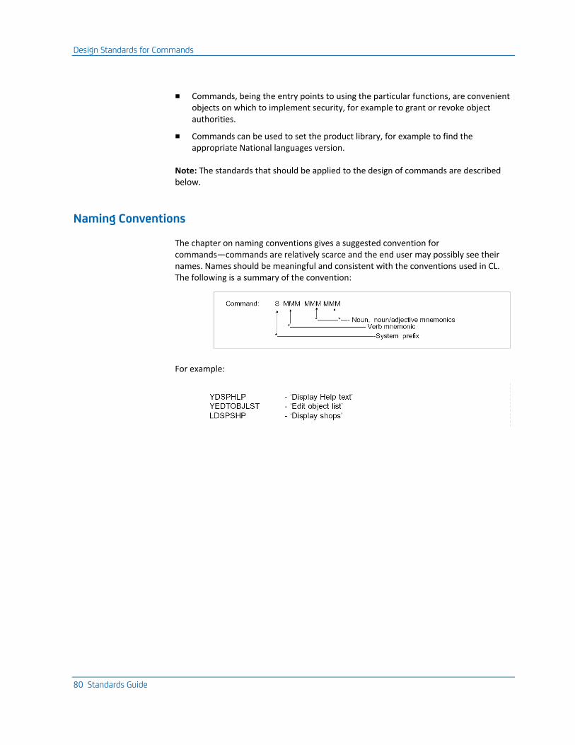
Design Standards for Commands
80 Standards Guide
■ Commands, being the entry points to using the particular functions, are convenient objects on which to implement security, for example to grant or revoke object authorities.
■ Commands can be used to set the product library, for example to find the appropriate National languages version.
Note: The standards that should be applied to the design of commands are described below.
Naming Conventions
The chapter on naming conventions gives a suggested convention for commands—commands are relatively scarce and the end user may possibly see their names. Names should be meaningful and consistent with the conventions used in CL. The following is a summary of the convention:
For example:
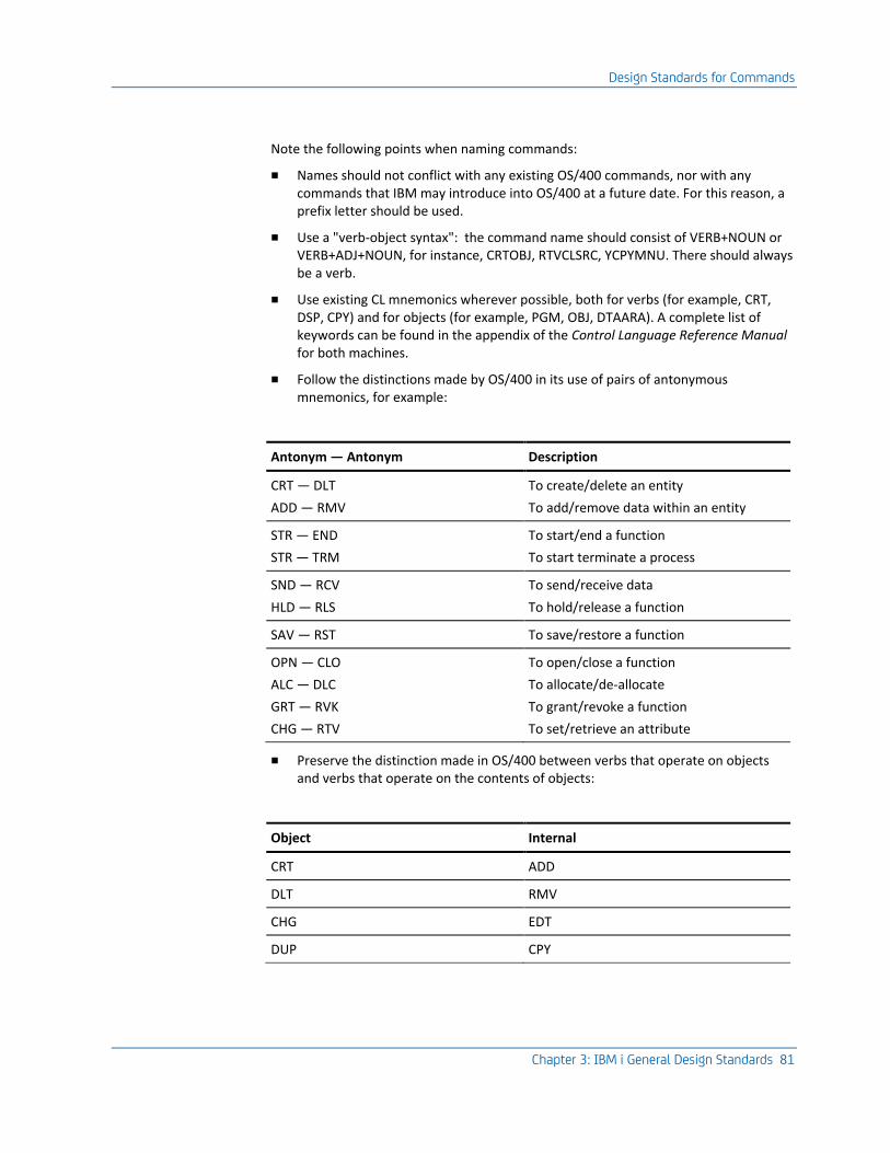
Design Standards for Commands
Chapter 3: IBM i General Design Standards 81
Note the following points when naming commands:
■ Names should not conflict with any existing OS/400 commands, nor with any commands that IBM may introduce into OS/400 at a future date. For this reason, a prefix letter should be used.
■ Use a "verb-object syntax": the command name should consist of VERB+NOUN or VERB+ADJ+NOUN, for instance, CRTOBJ, RTVCLSRC, YCPYMNU. There should always be a verb.
■ Use existing CL mnemonics wherever possible, both for verbs (for example, CRT, DSP, CPY) and for objects (for example, PGM, OBJ, DTAARA). A complete list of keywords can be found in the appendix of the Control Language Reference Manual for both machines.
■ Follow the distinctions made by OS/400 in its use of pairs of antonymous mnemonics, for example:
Antonym — Antonym Description
CRT — DLT
ADD — RMV
To create/delete an entity
To add/remove data within an entity
STR — END
STR — TRM
To start/end a function
To start terminate a process
SND — RCV
HLD — RLS
To send/receive data
To hold/release a function
SAV — RST To save/restore a function
OPN — CLO
ALC — DLC
GRT — RVK
CHG — RTV
To open/close a function
To allocate/de-allocate
To grant/revoke a function
To set/retrieve an attribute
■ Preserve the distinction made in OS/400 between verbs that operate on objects and verbs that operate on the contents of objects:
Object Internal
CRT ADD
DLT RMV
CHG EDT
DUP CPY
Design Standards for Commands
82 Standards Guide
■ Preserve the distinction made in OS/400 between working interactively on a list of entities (WRK verb) and working interactively on an individual entity (EDT or STR verb).
■ Follow the distinction made in OS/400 between operating on an object and operating on the description of an object; for instance, DSPSBS versus DSPSBSD.
Design Standards
Command syntax diagrams should be prepared for each command at the design stage. The diagrams should use the OS/400 standards.
For more information on conventions, refer to the OS/400 Control Language Reference Guide. For an example of conventions, refer to the appendix, "Programming and Coding Examples," in this guide.
Choosing Parameters
Command parameters should be ‘orthogonal’—each parameter should represent the values of only one variable. For example, rather than have four values for a parameter OUTPUT (values: *PRT, *DSP *PRTDTL, DSPDTL), you should have two separate parameters, OUTPUT (values: *, *LIST) and DETAIL (values: *PRT, *DSP). This allows future values to be added.
Keep the number of parameters to a minimum.
Do not place parameters specifying work management attributes (for instance job priority, switch settings, output queue) on commands, unless the command is specifically concerned with the initialization of a job or jobs; for example, a special version of the SBMJOB command. This is because it is generally preferable to control work management values through the job. Where it is useful to have an override on a particular command, you should make the default value to be that of the job (*JOB).
Design Standards for Commands
Chapter 3: IBM i General Design Standards 83
Order of Command Parameters
Use existing OS/400 syntax order whenever possible. For example, — LIB/FILE MBR
JOBNBR/USER/JOB
Place the parameters that are needed to identify the object or entity operated on by the command before any other parameters. For example, - EDTSRC FILE(X) OPTION(3).
Place the parameters that are most likely to be changed before the parameters that are unlikely to be changed; optimize for frequency of use. On iSeries, you should use the PMTCTL(*PMTCTL) keyword to hide ancillary parameters from the initial prompt displays—such additional parameters will automatically appear after the main parameters, if displayed by pressing F10. For example:
CRTPF FILE(QGPL/X) ........... AUT(*USE)
Place any required, for example, mandatory (MIN(0)) parameters, before any non-required parameters. Do not use the reordering facility of the command definition language to place required parameters after non-required parameters.
If either TEXT or OUTPUT parameters are present, they should normally be placed after all other parameters.
Command Parameter Keywords
Use existing CL keywords, such as FILE, OUTPUT, or TEXT whenever possible, not FL, FIL, OUTPT, TXT.
For more information on all of the CL keywords, refer to Appendix F of the iSeries (AS/400) Control Language Guide.
Keywords should be in the singular; for example FILE, not FILES.
If an entity type occurs more than once as a command parameter, distinguish between instances by an appropriate prefix on the keyword; for example, FROMFILE, TOFILE, FROMLIB, TOLIB. If it is creating a copy, you should use NEWxxx; for example, NEWOBJ.
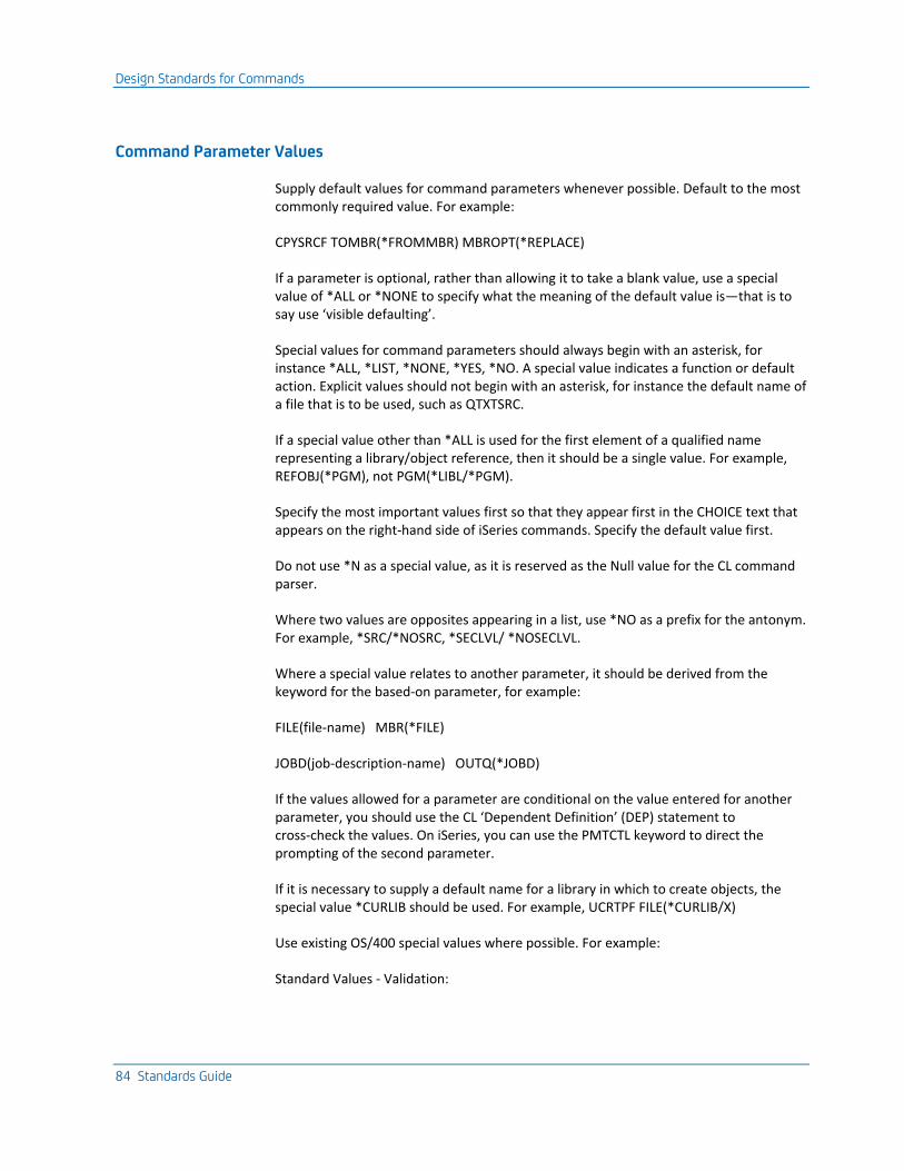
Design Standards for Commands
84 Standards Guide
Command Parameter Values
Supply default values for command parameters whenever possible. Default to the most commonly required value. For example:
CPYSRCF TOMBR(*FROMMBR) MBROPT(*REPLACE)
If a parameter is optional, rather than allowing it to take a blank value, use a special value of *ALL or *NONE to specify what the meaning of the default value is—that is to say use ‘visible defaulting’.
Special values for command parameters should always begin with an asterisk, for instance *ALL, *LIST, *NONE, *YES, *NO. A special value indicates a function or default action. Explicit values should not begin with an asterisk, for instance the default name of a file that is to be used, such as QTXTSRC.
If a special value other than *ALL is used for the first element of a qualified name representing a library/object reference, then it should be a single value. For example, REFOBJ(*PGM), not PGM(*LIBL/*PGM).
Specify the most important values first so that they appear first in the CHOICE text that appears on the right-hand side of iSeries commands. Specify the default value first.
Do not use *N as a special value, as it is reserved as the Null value for the CL command parser.
Where two values are opposites appearing in a list, use *NO as a prefix for the antonym. For example, *SRC/*NOSRC, *SECLVL/ *NOSECLVL.
Where a special value relates to another parameter, it should be derived from the keyword for the based-on parameter, for example:
FILE(file-name) MBR(*FILE)
JOBD(job-description-name) OUTQ(*JOBD)
If the values allowed for a parameter are conditional on the value entered for another parameter, you should use the CL ‘Dependent Definition’ (DEP) statement to cross-check the values. On iSeries, you can use the PMTCTL keyword to direct the prompting of the second parameter.
If it is necessary to supply a default name for a library in which to create objects, the special value *CURLIB should be used. For example, UCRTPF FILE(*CURLIB/X)
Use existing OS/400 special values where possible. For example:
Standard Values - Validation:
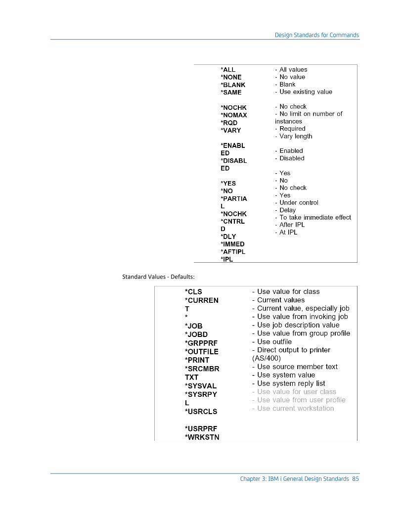
Design Standards for Commands
Chapter 3: IBM i General Design Standards 85
Standard Values - Defaults:
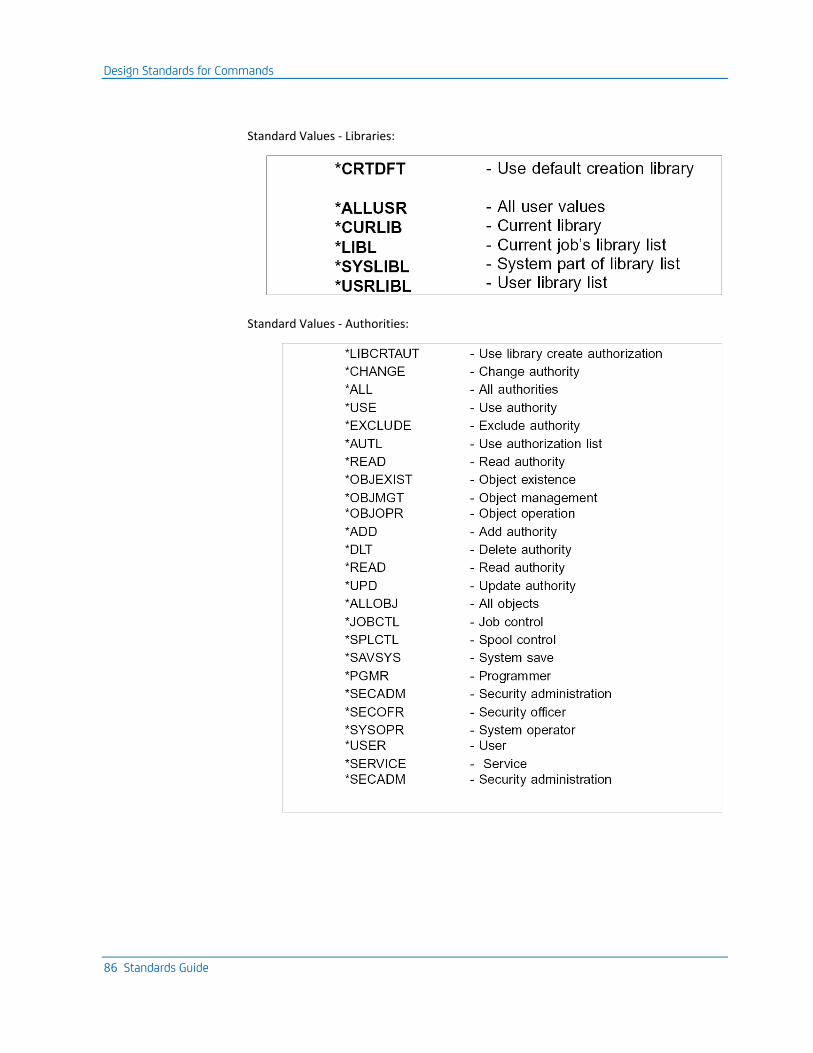
Design Standards for Commands
86 Standards Guide
Standard Values - Libraries:
Standard Values - Authorities:
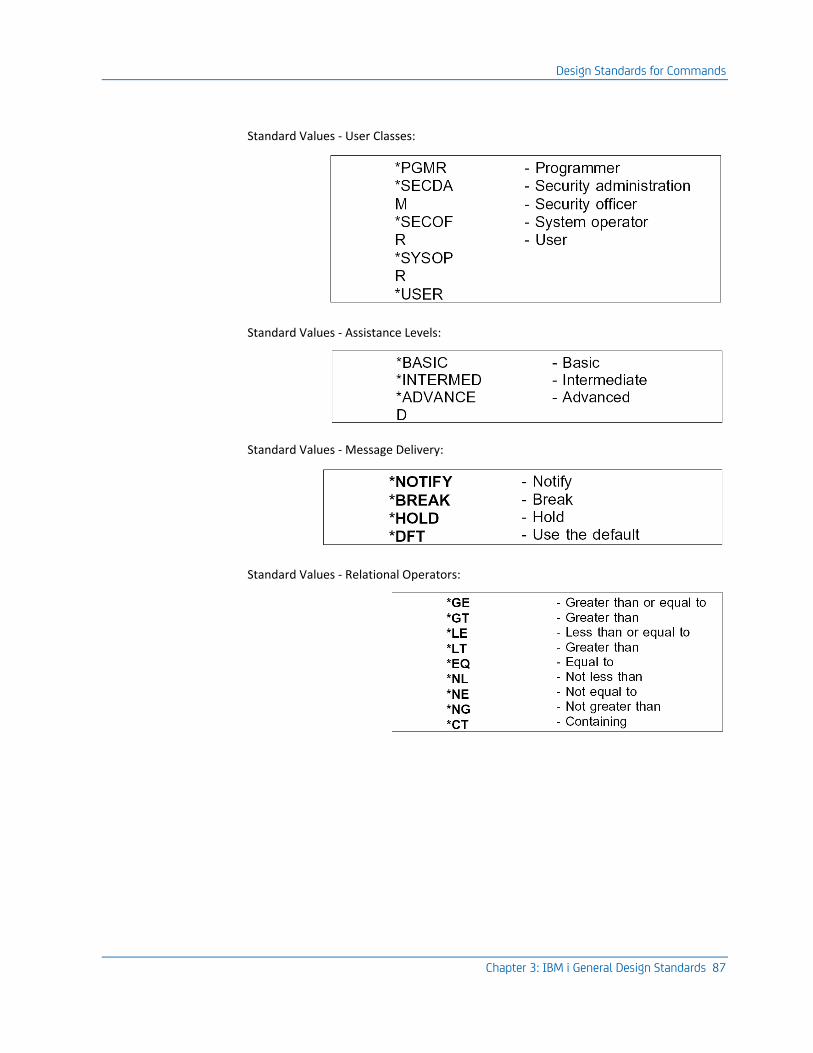
Design Standards for Commands
Chapter 3: IBM i General Design Standards 87
Standard Values - User Classes:
Standard Values - Assistance Levels:
Standard Values - Message Delivery:
Standard Values - Relational Operators:
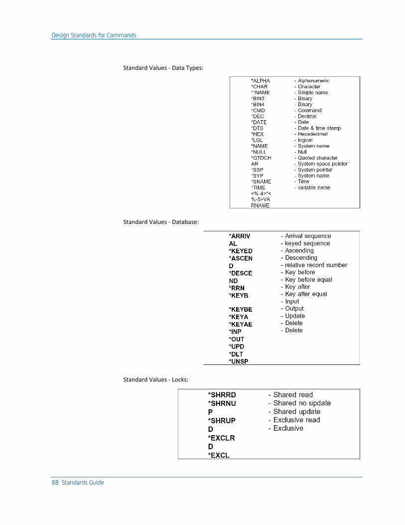
Design Standards for Commands
88 Standards Guide
Standard Values - Data Types:
Standard Values - Database:
Standard Values - Locks:
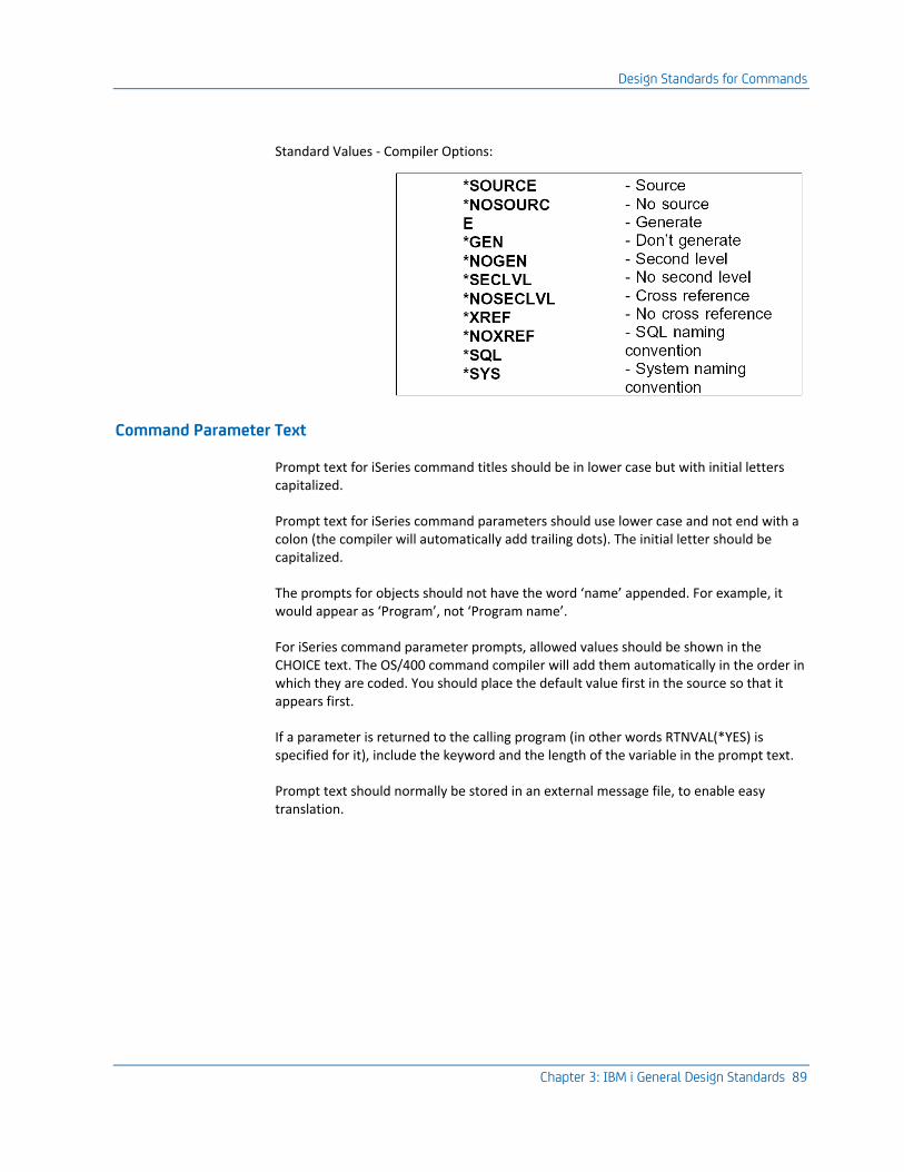
Design Standards for Commands
Chapter 3: IBM i General Design Standards 89
Standard Values - Compiler Options:
Command Parameter Text
Prompt text for iSeries command titles should be in lower case but with initial letters capitalized.
Prompt text for iSeries command parameters should use lower case and not end with a colon (the compiler will automatically add trailing dots). The initial letter should be capitalized.
The prompts for objects should not have the word ‘name’ appended. For example, it would appear as ‘Program’, not ‘Program name’.
For iSeries command parameter prompts, allowed values should be shown in the CHOICE text. The OS/400 command compiler will add them automatically in the order in which they are coded. You should place the default value first in the source so that it appears first.
If a parameter is returned to the calling program (in other words RTNVAL(*YES) is specified for it), include the keyword and the length of the variable in the prompt text.
Prompt text should normally be stored in an external message file, to enable easy translation.
Design Standards for Database Files
90 Standards Guide
Required Parameters for Commands
Commands that are to be run in batch should not have optional parameters that will invoke functions requiring interactive intervention; if a command can be used in batch, it should be usable in all circumstances.
Note: An example of where this rule is violated can be found in the CA 2E Toolkit Build object list (YBLDOBJLST) command. It is possible to use the YBLDOBJLST command in batch, but if a value of FILTER(*YES) is specified, it will crash when it attempts to prompt for filtering values.
If RTNVAL(*YES) is specified for a command parameter, MIN(1) should also be specified. If the command is for use in CL programs and is to have a value returned to it, it should be compulsory. If MIN(1) is not specified, execution of the command may result in the Command Processing Program (CPP) attempting to return a value to a non existent parameter (there is no way of detecting a null pointer in a HLL CPP).
Design Standards for Database Files
A good database design is crucial for the success of any application system. To achieve such a design, you should be aware of what database facilities are available on iSeries and use design techniques that help you take advantage of the facilities.
This section provides some guidelines for designing databases for iSeries, including recommendations for data modeling and normalization.
Design Goals
Your goal is to design databases that are:
■ Comprehensive: Every item of information that is relevant to the organization should be recorded (provided that it is cost effective to do so).
■ Non-redundant: Every item of information should appear only once. This not only saves resources, but also ensures that the data is concurrent; that the computer does not hold two conflicting versions of what should be the same item of data.
■ Consistent: There should be no mutually incompatible representations of information, nor conflicting rules about what can be done with the data, so that system data integrity can be preserved. Data modeling can assist you to achieve this aim.
■ Efficient: The access times to retrieve or process data should meet the business requirements. Some consideration of the processes that will operate upon the database is necessary to check that this aim is satisfied.

Design Standards for Database Files
Chapter 3: IBM i General Design Standards 91
The Database of iSeries
The database of iSeries is based upon relational database principles. Relational databases are built on a body of formal mathematical work on the optimal way of structuring data. An understanding of the principles of the relational theory is vital for good database design.

Design Standards for Database Files
92 Standards Guide
The iSeries Database as a Relational Database
In essence, the database of iSeries is relational—data is kept in ‘flat’ tables and may be assembled into logical views. It has facilities for building access paths to assemble, order, and select data. The database has built-in facilities for recovery (via journaling and commit control), security, integrity, and concurrency control. It falls short however, of the full theoretical implementation of a relational database in a number of ways.
For instance:
■ The relational terminology of tables, columns, and rows is not used.
■ A metamodel is not available to describe the database handler’s own facilities with the same mechanisms as the database that it produces.
Much of the system information may, however, be materialized into an accessible format using the OUTFILE parameter on the various OS/400 display commands. From V2R1, there are also APIs to retrieve some of the information. The SQL/400 interface to the database has SQL catalog facilities that may be queried, using SQL.
■ The join facilities of the OS/400 database are limited—they are read only, and limited to an equi-join. If fields from the secondary join file are used as keys (for instance with the OS/400 Open query file (OPNQRYF)) command, then true concurrency is not maintained.
■ In the native interface, there are only limited facilities for manipulating sets of data within the database, and these are not presented explicitly in terms of the operations of the relational calculus (Union, Intersection, Subtraction, Addition, Select, Project, and Join) acting upon sets.
Selection can be specified in DDS (but is early binding).
A join can be specified in DDS (but is early binding). Fields from the secondary join file may not be used as key fields. The HLL read equal statement (for instance RPG III ‘READE’,) gives what is in essence access to a set of data.
Set level operations are of significance in that they provide a greater level of economy in specifying programs—in relational languages such as SQL, a single statement may often serve to specify what would be in most HLL’s be a ‘Do loop’ containing many lines of code.
The OPNQRYF command allows for dynamic joins and selections.
SQL/400 provides join specifications and a number of set level operations.
■ There is not a full capability for field level security. It is possible however, to build logical views containing only a subset of the fields in the file and to restrict authority differently to different views.
■ There are only limited capabilities for specifying rules for preserving the integrity of the database. Any further rules have to be incorporated explicitly in HLL code. For instance:
Design Standards for Database Files
Chapter 3: IBM i General Design Standards 93
■ to test that foreign keys (that is, non-key fields on a file which are themselves the keys of other files) match prime key values
■ to test that instances of referenced keys cannot be deleted if they are used in dependent relations ("referential integrity")
■ There is not proper support for a null value. This is significant because in a truly relational database, primary keys must not be null ("Entity integrity must be preserved").
■ In device file DDS, a blank value cannot be distinguished from a null value.
■ Many features of the database are "early binding"—facilities such as selection and key order are built into a compiled object. Although this gives a better performance, it also limits the flexibility of the database.
■ Relations are implicit—from the presence of fields on files—rather than explicit.
Overall, the database of iSeries can be characterized as relational, but ‘early binding’—information about how to use the database information is incorporated at compile time rather than execution time.
Data Modeling
The fact that iSeries has reasonably-sophisticated databases does not guarantee that you will automatically achieve a sophisticated and reasonable database design. To achieve the design goals given above, you will need to discover the correct structure of your data, in particular to examine it for all forms of redundancy. To do this, the techniques of data modeling may be used. Data modeling provides a formal method for transforming business goals into a database design as follows:
CA 2E includes a data modeling tool that enables you to design a database, and then implement it.
Note: A full discussion of how to turn a business model into a data model, or a data model into a database design, is beyond the scope of these standards. There are, however, various points about the database of iSeries that analysts new to the machine may find useful, and also a few guidelines that programmers new to analysis may find helpful.
For more information on data modeling, refer to Defining a Data Model.
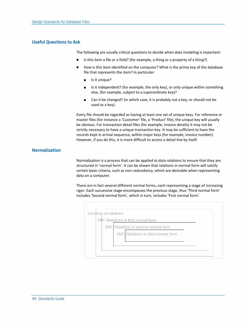
Design Standards for Database Files
94 Standards Guide
Useful Questions to Ask
The following are usually critical questions to decide when data modeling is important:
■ Is this item a file or a field? (for example, a thing or a property of a thing?)
■ How is this item identified on the computer? What is the prime key of the database file that represents the item? In particular:
■ Is it unique?
■ Is it independent? (for example, the only key), or only unique within something else, (for example, subject to a superordinate key)?
■ Can it be changed? (in which case, it is probably not a key, or should not be used as a key).
Every file should be regarded as having at least one set of unique keys. For reference or master files (for instance a ‘Customer’ file, a ‘Product’ file), the unique key will usually be obvious. For transaction detail files (for example, Invoice details) it may not be strictly necessary to have a unique transaction key. It may be sufficient to have the records kept in arrival sequence, within major keys (for example, Invoice number). However, if you do this, it is more difficult to access a detail line by itself.
Normalization
Normalization is a process that can be applied to data relations to ensure that they are structured in ‘normal form’. It can be shown that relations in normal form will satisfy certain basic criteria, such as non-redundancy, which are desirable when representing data on a computer.
There are in fact several different normal forms, each representing a stage of increasing rigor. Each successive stage encompasses the previous stage, thus ‘Third normal form’ includes ‘Second normal form’, which in turn, includes ‘First normal form’.
Design Standards for Database Files
Chapter 3: IBM i General Design Standards 95
The steps of normalization can be outlined in a non-technical language by using the term ‘field’ rather than the more correct attribute as follows:
■ To be in first normal form, every field must represent an atomic set of values. A field should not, for example, contain both customer code and customer type (either concatenated or as alternatives).
■ To be in second normal form, every non-key field in the table (for example, record) must depend on the prime key. For example, properties of customer type should be on a separate customer type entity, and not be repeated on every customer instance.
■ To be in third normal form, every non-key field must be:
■ mutually independent of the other non-key fields (it can, for instance, be updated independently of the other non-key fields)
■ fully dependent upon the prime key
Considerations for Database File Design
Even if you do not have a data modeling tool, it is beneficial to use data modeling techniques, and in particular, to design in terms of a logical schema that represents the overall structure of your organization’s data. The logical schema can then be translated into a physical schema that gives an efficient implementation.
On the first design pass, ignore interrogation requirements. An accurate business data model will normally permit sensible interrogation. When the essential model is established, test it against interrogation requirements. In particular, you may wish to introduce redundancy in order to achieve faster access. Where redundancy is introduced, only one occurrence of the redundant fields should be regarded as definitive, and it should be made clear which occurrence this is. For instance, in order to provide rapid response for telephone ordering, you might provide a current outstanding credit total for a customer as a summary field, although it is theoretically possible to build the figure up from outstanding invoices and orders.
■ You will usually find that the user has a very good intuitive feel for the data that he handles. Ask for a critique of a non-technical presentation of your data model.
■ Never allow programming to proceed until you are entirely satisfied with your data model. The accuracy of the data model in its relation to the business is by far the most important feature of a design.
Design Standards for Database Files
96 Standards Guide
Design Tips for OS/400 Databases
Design strictly in terms of externally defined files; field offsets must not be conditional. Do not specify that a field is to represent one data item in some circumstances and a totally different data item in other circumstances. Instead, introduce a separate field.
Avoid repeating groups of items within a record. For instance, ‘Order quantity 1’, ‘Order quantity 2’ ‘Order quantity 3’. In a database of fixed length records like that of iSeries, unnormalized data of any repeating group imposes a limitation on the number of groups allowed. It also requires more complicated programming.
Do not concern yourself with design detail, in particular, field attributes such as lengths, edit codes, and allowed values, until you have established what the contents of your data model should be. Then, create a field reference file (FRF) entry for each field description, and refer every occurrence of the field to the FRF entry. For example, the FRF will contain a definition for Customer number, to which Customer numbers in the Sales order, Sales ledger, and Sales analysis files will refer. Every different type of date should have its own FRF entry: Date of birth, Expiry date, Order date. One of them may one day need to be changed to a different format. Define total and accumulator fields as having the base field length + n digits.
On your later design passes, consider interrogation requirements, especially if a rapid response is required. IBM gives a performance guideline of not more than 25 database accesses per transaction. The ‘Join’ operation may be used to lessen the need to introduce redundancy to achieve performance.

Design Standards for Database Files
Chapter 3: IBM i General Design Standards 97
General Points for Field Usage
Place key fields before other fields in the file. Place major keys (for example, keys fields which are also the keys of other files) before minor keys.
Place other fields on the file in the order in which they generally appear on input and output displays. This makes the use of software tools that create device file layouts directly from the database file (such as Query) easier.
Even if all the values for a code will be numeric, define the code field as being character rather than numeric. It will then be possible to introduce character codes at a later date if the numeric code values have all been employed. It will be also easier to program an enquiry function to display the allowed values for the field because a ‘?’ may be entered directly into the code field—OS/400 does not permit the entry of a ‘?’ into numeric fields.
Avoid the use of zoned numeric fields. The native storage format for numeric fields on iSeries is packed, so it is more efficient to pack numeric fields.
Packed fields should be defined with an odd number of digits, even if this makes the field a digit larger than is actually required. This is because:
■ even-length packed fields are less efficient than odd-length fields
■ no additional storage is required
■ it is not possible in RPG III to define a packed field of even length within a data structure
Note: Blank or zero values should not generally be allowed for prime keys, since they represent a null value. If they are required, try to assign some other value to represent a null value. For instance ‘-99999’ for a numeric field, ‘*NONE’ for an alphanumeric field.
Design Standards for Database Files
98 Standards Guide
Categories of Database File
In designing application systems, it is often useful to differentiate between different types of files on the basis of the type and latency of data the files hold. Different design considerations apply to each of the five categories of files discussed:
■ Reference data: master files and tables
■ Transaction data
■ Transaction summary data
■ Archive files
■ Work files
Note: Frequency of use and of turnover, which is the primary consideration in categorizing files in the above scheme, is also the main criterion for selecting a backup strategy for saving data to an offline medium.
Note: Avoid designing files that have a ‘mixed’ function.
Reference Data Files
Reference data files contain system reference tables and codes, for example, a customer file, VAT code file, or address file. The files are relatively small; their contents are relatively constant over time (they are "non-volatile"), and many programs usually refer to the files in the system.
Do not mix reference and transaction summary data in the same file. The two types of data have different activity levels. Except when actually being maintained, usage of reference files should be "read only".
Where the applicability of a reference file record is time dependent, for example, for a currency or a price rate, cancellation of a record should be recorded via an "active date", or an "inactive date", not by a marker. Users will rarely cancel a record at the precise time at which it becomes inactive. Consider an "active date" to permit items to be entered in advance of their availability for processing.
Consider, where appropriate, providing an indication that the code defined by a record has been referenced by a transaction. This helps to preserve the referential integrity of the database: a record in use may not be deleted. Users may however create "provisional" records that are subsequently never referenced, and may be purged.
Design Standards for Database Files
Chapter 3: IBM i General Design Standards 99
Transaction Data Files
Transaction files contain the main system data. They are generally large, and have a high turnover. They may well require frequent archiving.
Certain reference data will attach to each transaction. Consider whether the historic or the current view, or both, is relevant in subsequent interrogation. For example, does the sales manager need sales reported by the customer’s representative at the time of the sale, or by the customer’s current representative? In the former case, the representative must attach to the transaction; in the latter case, it should not.
Consider the latency of the data. A sales invoice record is current only so long as it is outstanding, however, the same data may be required for sales analysis over a much wider time span. The same data thus services two different information needs.
Transaction Summary Files
Transaction summary files contain summaries of the transaction files.
Introduce summary files to provide summary totals of transactions for rapid interrogation, for example customer’s aged debt, and stock levels. They impose an overhead on processing, and may restrict interrogation possibilities if no supporting detail is maintained.
Introduce summary files only when space or response considerations mitigate against maintaining and interrogating open item transaction files.
Try to design summary files so that they can be rebuilt from the transaction files in the event of an error or a crash.
Archive Files
Archive files are used to hold obsolete data, usually from the transaction files, but sometimes from the reference files as well.
Archive files may be introduced to contain transactions no longer current. Before introducing such files, investigate the user’s requirement carefully. It is attractive in principle to have two years’ sales history on line, but is there a valid business need?
Wherever possible, archive files should use the same format as current transaction files. Interrogation programs may then use either.
Design Standards for Database Files
100 Standards Guide
Work Files
Work files are used to facilitate processing.
Decide whether the work file will be required just for the job in hand (for example, for a print program), or whether it must exist from job to job (for example, a batch entry work file). In the first case, it will probably be best to create a copy of the file in QTEMP, while in the latter case, it would be better to use a work member within a permanent file.
Consider the recovery and cleanup implications. Can the work file be thrown away or not?
Work files can be useful for reducing the number of database accesses required to interrogate the database, especially where data is to be selected on one access key but ordered on another. The method is not so much to use them as sort files, but rather to provide project and/or join operations that simplify programming. Records can be extracted from the database using the most efficient existing logical view (the OS/400 Copy file (CPYF) command is often sufficient to make the extraction). A logical file may then be built upon the extracted data, and the data presented, using a simple report program.
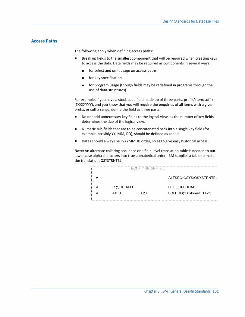
Design Standards for Database Files
Chapter 3: IBM i General Design Standards 101
Access Paths
The following apply when defining access paths:
■ Break up fields to the smallest component that will be required when creating keys to access the data. Data fields may be required as components in several ways:
■ for select and omit usage on access paths
■ for key specification
■ for program usage (though fields may be redefined in programs through the use of data-structures)
For example, if you have a stock code field made up of three parts, prefix/stem/suffix (ZXXXYYYY), and you know that you will require the enquiries of all items with a given prefix, or suffix range, define the field as three parts.
■ Do not add unnecessary key fields to the logical view, as the number of key fields determines the size of the logical view.
■ Numeric sub-fields that are to be concatenated back into a single key field (for example, possibly YY, MM, DD), should be defined as zoned.
■ Dates should always be in YYMMDD order, so as to give easy historical access.
Note: An alternate collating sequence or a field level translation table is needed to put lower case alpha characters into true alphabetical order. IBM supplies a table to make the translation: QSYSTRNTBL.
Design Standards for Programs
102 Standards Guide
Access Path Performance Considerations
An excessive number of access paths can have a serious impact on performance. Note the following points:
■ Access paths that are required only for occasional batch jobs (for example, for reports), should be specified with delayed access path rebuild. A value of MAINT(*REBLD) on the OS/400 ‘Create file’ commands (CRTPF or CRTLF).
■ Keep the number of immediate maintenance access paths on a given physical file within reason, for example, minimize the number of operational indices.
■ If a large number (IBM cites a value of more than 10 percent) of databases add are taking place in a batch procedure, it is quicker to remove all non-essential access paths and add them back afterwards.
■ An access path determines:
■ The order that records are presented
■ The criteria that are to be applied to select or omit records
■ Which fields from the records are to be included. A particular use of this is to restrict access to particular fields on a database file
For a given file, the number of useful ways of selecting or omitting the data is usually far greater than the number of useful ways of ordering the data. For this reason, it is often a good idea to leave the selection to the programs that read the file, or to use a ‘dynamic’ access path—rather than building it into the access path permanently (‘static’ selection). This is particularly true when the ‘cardinality’ of each key set (for example, number of records with the same key, or partial key, that have to be read), is small.
■ OS/400 will automatically share the access paths of files which have the same keys. If you are specifying select or omit criteria using the database facilities, consider using ‘dynamic’ rather than ‘static’ selection, so as to allow sharing of access paths.
Design Standards for Programs
Program design needs to be considered both generally, covering issues such as modularization, structured design, encapsulation, and interface principles, and specifically, looking at issues such as code structure, choice of HLL, syntax, naming conventions, and the use of data types.
Design Standards for Programs
Chapter 3: IBM i General Design Standards 103
Design Goals
You should try to design your programs so that they satisfy the following overall design goals.
Programs should be:
■ Correct: Above all, programs should do what they are meant to do. The simpler and clearer both the design and specification are, the more likely this goal is to be achieved. The use of standard program types can help simplify the specification of the design and reduce the likelihood of errors in the logic. More formally, programs should generally follow structured principles, for example, be made up of constructs which can be transparently replaced with prime structures.
■ Transparent: Programs should be as readable and as understandable as possible. This requires that you structure programs sensibly, avoid tricky programming, document properly, and use helpful names, notations, and standard techniques.
■ Modular: Programs should be as modular as possible, so that changes to any one part have a minimal effect on other parts. You should also design to be independent of any system specific facilities.
■ Robust: Programs should handle any routine errors sensibly without crashing. If a serious error occurs, they should preserve the integrity of the database and collapse in a tidy manner; for example, not leave objects allocated or locked.
■ Efficient: Programs should perform their function in a way that uses as little machine resource as possible.
Program Types
Just as there are types of buildings, the instances of which, although individually different, are within type all fundamentally similar by the very nature of the purpose they are intended to fulfill, so are there program types, whose structure is dictated by the underlying structure of the data on which they operate.
An effective use of program type can vastly increase productivity. If programs are written to be as data independent as possible, then writing a program of an existing type to work on a new file is mainly a matter of changing the names of the references to the external database. Changing names is a much less error prone process than changing logic.
Such an approach is carried to its logical conclusion in CA 2E, which has a number of standard program types. Each program type is available to operate on any file in the database—nominating a file and a function type is sufficient to specify an entire program.
You should try to design your application using standard types, in as ‘pure’ or unmodified of a form as possible.
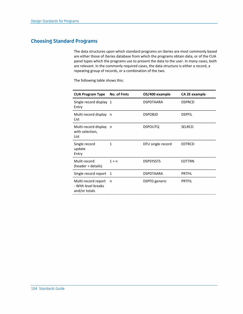
Design Standards for Programs
104 Standards Guide
Choosing Standard Programs
The data structures upon which standard programs on iSeries are most commonly based are either those of iSeries database from which the programs obtain data, or of the CUA panel types which the programs use to present the data to the user. In many cases, both are relevant. In the commonly required cases, the data structure is either a record, a repeating group of records, or a combination of the two.
The following table shows this:
CUA Program Type No. of Fmts OS/400 example CA 2E example
Single record display Entry
1 DSPDTAARA DSPRCD
Multi-record display List
n DSPOBJD DSPFIL
Multi-record display with selection, List
n DSPOUTQ SELRCD
Single record update Entry
1 DFU single record EDTRCD
Mulit-record (header + details)
1 + n DSPSYSSTS EDTTRN
Single record report 1 DSPDTAARA PRTFIL
Multi-record report - With level breaks and/or totals
n DSPFD generic PRTFIL
Design Standards for Programs
Chapter 3: IBM i General Design Standards 105
Organizing Programs into Modules
Organizing the functions of your application system allows you to:
■ insulate against change
■ allow independent development and testing
■ simplify the design
■ make the system more robust
Modularization should serve to hide most of the internals of the module. The interface to each module should explicitly reference all the information required to use the module, and be the only way of invoking the module.
Modules should be chosen according to a number of criteria. Each module should be concerned with one fundamental task and should not carry out functions that are similar to or overlap with any other module—it should be ‘orthogonal’. Each module should have strong internal cohesion and weak coupling with other modules.
Coupling and Cohesion
In deciding how to modularize a system, pay attention to the concepts of coupling and cohesion—only combine related functions into a module, minimize the interfaces between modules; and do not pass complicated directives from one module to another.
Coupling
Coupling is a measure of the interdependence of two modules. The closer two procedures are coupled, the harder it is to design, test and rely on them as separate modules. We can identify a continuum of degrees of coupling, ranging from the strong to the weak. Generally speaking, the weaker the coupling, the better.
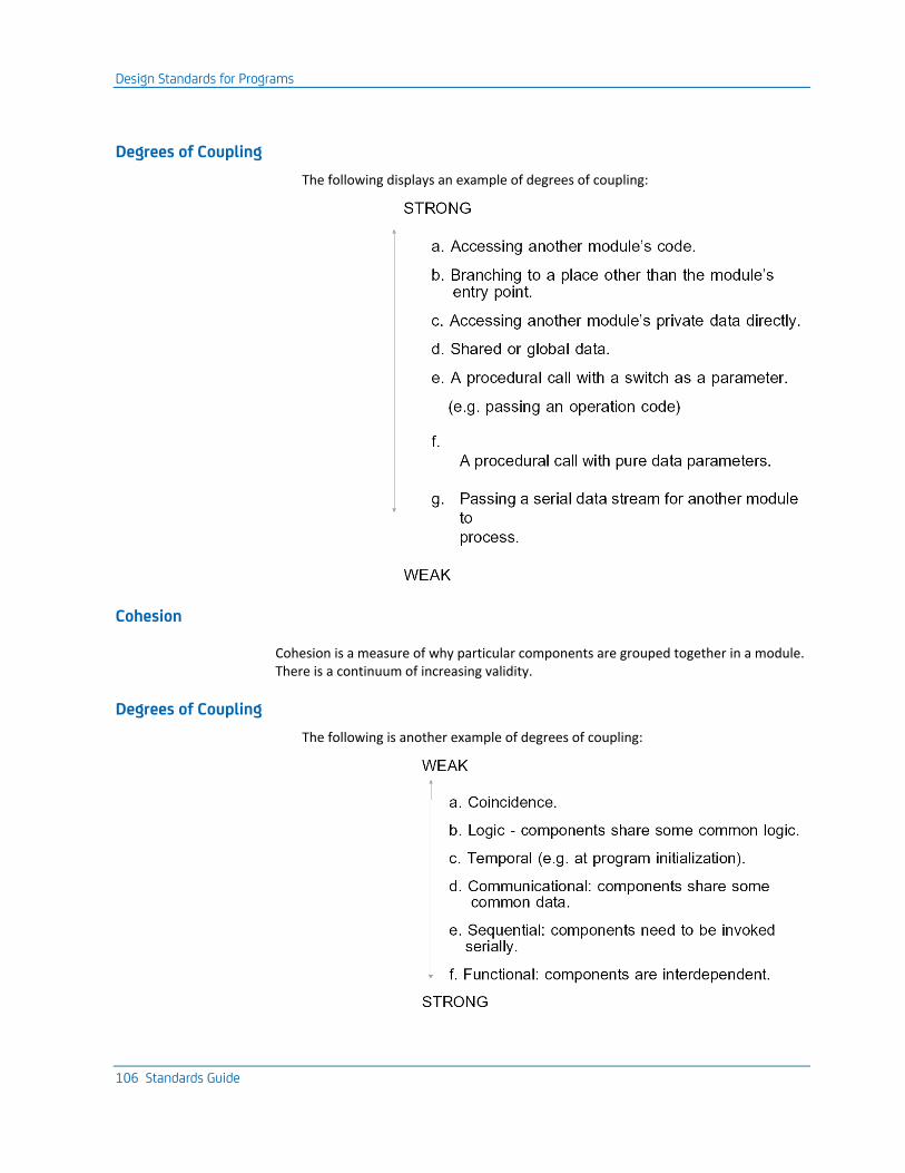
Design Standards for Programs
106 Standards Guide
Degrees of Coupling
The following displays an example of degrees of coupling:
Cohesion
Cohesion is a measure of why particular components are grouped together in a module. There is a continuum of increasing validity.
Degrees of Coupling
The following is another example of degrees of coupling:
Design Standards for Programs
Chapter 3: IBM i General Design Standards 107
Program Modularization
The following practical rules can be applied to the modularization of programs:
■ Do not combine unrelated or weakly related functions onto the same panels. For example, one panel, one task is easier to understand, program, and maintain.
■ Place commonly required functions into standard type subprograms; for example code validation, enquiry functions. This allows faster, less error-prone coding.
■ Both capability checking (whether a user is allowed to carry out a task) and entity manipulation (for example, the creation and deletion of records representing entities) are generally best modularized into standard functions.
■ Provide a single entry and exit point.
■ Do not place repeatedly required subroutines in programs using automatic storage allocation (PASA), for example, CL programs. The repeated re-initiation overhead is very high. Instead, use programs written in a language employing static storage allocation (PSSA), for example, RPG III, and do not close down the program when exiting from the programs.
■ Alternatively, it may be more efficient to place a sub-function that is to be repeatedly called into a subroutine (once per record read when reading a large dbf).
■ It is more important to have well structured, clearly written programs that are easy to understand and to maintain, than to have programs optimized to the last byte and call. ("It is easier to make a working program fast than a fast program work").
■ Do not attempt too much in one program. A rule of thumb for RPG III programs is that programs start becoming unwieldy at 1,200 lines, are quite large enough at 1,500, and are getting unmanageable at 1,700 lines. At 2,000 lines, they are epic. (Ideally RPG III programs should be less than 700 lines).
Remember that RPG III and COBOL programs cannot be called recursively; for example, twice in the same invocation stack for a job. This puts limitations on how programs can be linked together. For example, if a maintenance program ca CAll an inquiry program, and the inquiry program ca CAll the maintenance program, the situation might arise whereby a recursive call is attempted.
Note: You may achieve a logical or design modularization which may be implemented in a redundant manner; for instance by the use of /COPY or %INCLUDE members in HLLs, or by the use of CA 2E internal functions.
The interface between any two programs can be regarded as a database format; it may be implemented as such, using externally-described data structures in order to allow for change.

Design Standards for Programs
108 Standards Guide
Error Recovery
When designing an application, you should consider what would happen when an error occurs, both normally (data validation error), and abnormally (system crash).
The following are some principles that can be applied when designing for error recovery. Refer to the section on ‘System Recovery’ for a general discussion of recovery considerations.
In the event of a crash, programs should always collapse to a safe point that is one where no special corrective intervention will be required to synchronize the database. Commit control can be used to ensure that this happens, even on transactions involving many updates to the database.
Decide what the recovery unit will be should a crash occur. A critical consideration is usually whether the whole file can be regarded as recoverable as a single unit or not; this is normally equivalent to considering whether many users will be using the file at the same time.
If the file may be regarded as a single recovery unit; for example, during its use for update by a batch process, the whole file may be restored from a backup copy, taken at the start of the process.
If the whole file cannot be restored, say because of locks likely to be held by other users, (for instance as when one of several interactive programs using a file fails), the recovery unit cannot be the whole file. Journaling can be used to select a recovery unit within a file—recovery units can range from the whole job down to an individual access to the database. Commit control can be used to group individual database accesses into functionally useful recovery units (for example, a whole batch of transactions).
Make programs restartable. Programs should be written so that when they are rerun after a crash, they pick up where they left off, and resume processing.
You should be able to reassure yourself that a system is synchronized after a crash—provide inquiry programs and integrity checkers.
Design Standards for Programs
Chapter 3: IBM i General Design Standards 109
Error Handling
Good error handling design should serve to contain the damage from errors. Errors should be brought to the operator’s attention, but the system should retain its integrity, and, if possible, continue.
In general, you should aim for defense in depth. Assume things will go wrong at every level.
The default error handling features of OS/400 provide an excellent framework for error handling, and can be used as the norm. The only design decision required is as to when, if ever, you should override the handling with your own processing.
Errors fall into three general classes:
■ Application generated (for example, "record not found"), since you create the messages you are handling them by definition.
■ System generated, because of pathological errors (for example, decimal data errors, errors due to missing programs or files). Do not attempt to handle pathological errors. Let the message handling capabilities of OS/400 force a request for the operator’s attention.
■ System generated because of routine errors (for instance, due to record locks). You will probably want to handle such errors explicitly so that automatic recovery can take place and processing can continue.
One of the main differences between the design requirements of batch and interactive programs lies in the error handling.
For interactive programs, error handling is relatively straightforward. An error message can be issued, suggesting one or more options, and the program can wait for immediate guidance. Where a partial update has taken place, it is possible to indicate what has and what has not been implemented.
For batch programs, error handling is more complicated. You must allow for errors of varying levels of severity, ranging from terminal errors, which require immediate and complete abortion of the process, to warning errors, which require the program to take default action in order to be able to continue unattended. In any case, the operator needs to be alerted as to the potential problems. You should also consider whether, if a fatal error occurs, subsequent jobs should be allowed to continue.
OS/400 error handling imposes a certain overhead. You should code so that exception handling is invoked on the least used path. For example, say that you are adding/updating records on a file. If the record will not normally already exist on file, you should attempt to add the record, and monitor for an exception, in which case, you will chain and update the record, rather than vice versa.
Design Standards for Programs
110 Standards Guide
Record Locking
Always make allowance for the possibility of records being inaccessible due to locks by another job. In RPG III, this should normally consist of testing the result indicator (col 56-57) on file access operations. The appropriate action to take will depend upon the context.
For single record updates in interactive programs, it will normally be sufficient to abandon the update and report a ‘record in use’ error message.
For multiple record updates in interactive programs, and all batch updates, you will either need to rollback and report a ‘record in use’ error message, or carry out whatever partial update is still feasible. In the latter case, you must be able to report back what has, and what has not, been updated.
Note that file design may be used to reduce multiple record updates to what are effectively single record updates. Potential lock situations can usually be designed out of an application. For instance, if an invoice maintenance program requires a lock on the invoice header before it will allow editing of invoice details, it will probably not be necessary to check for locks on the invoice detail records.
There are two basic strategies that can be adopted with regard to the locking of data records:
■ Pre-allocation: A record that is to be updated is locked before the data to update the record is processed. The lock is held until the update is completed. This method allows for simple programming and may be appropriate for interactive programs, when the files that are being updated are not required for update by other processes at the same time.
■ Rollback: A record that is to be updated is locked only for the instant of update. This generally removes problems of contention. However, it requires an extra database read, and if the update is being done on the basis of existing record values, it will usually require programming to check that a record has not been altered by another process between the initial access and the actual update. If such an update has taken place, it will be necessary to report the error, and it may be necessary to execute a rollback to undo any associated updates that have already been completed on the premise that a record could be updated (for example, update of a batch header before update batch records).
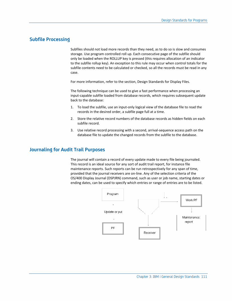
Design Standards for Programs
Chapter 3: IBM i General Design Standards 111
Subfile Processing
Subfiles should not load more records than they need, as to do so is slow and consumes storage. Use program controlled roll up. Each consecutive page of the subfile should only be loaded when the ROLLUP key is pressed (this requires allocation of an indicator to the subfile rollup key). An exception to this rule may occur when control totals for the subfile contents need to be calculated or checked, so all the records must be read in any case.
For more information, refer to the section, Design Standards for Display Files.
The following technique can be used to give a fast performance when processing an input-capable subfile loaded from database records, which requires subsequent update back to the database:
1. To load the subfile, use an input-only logical view of the database file to read the records in the desired order, a subfile page full at a time.
2. Store the relative record numbers of the database records as hidden fields on each subfile record.
3. Use relative record processing with a second, arrival-sequence access path on the database file to update the changed records from the subfile to the database.
Journaling for Audit Trail Purposes
The journal will contain a record of every update made to every file being journaled. This record is an ideal source for any sort of audit trail report, for instance file maintenance reports. Such reports can be run retrospectively for any span of time, provided that the journal receivers are on-line. Any of the selection criteria of the OS/400 Display Journal (DSPJRN) command, such as user or job name, starting dates or ending dates, can be used to specify which entries or range of entries are to be listed.
Design Standards for Programs
112 Standards Guide
The Journal as a Debug Aid
The journal can be used to trace the cause of anomalies in the database. Most notably, the updates made to the database by a particular program can be examined in detail, or the program responsible for a particular update can be discovered.
Choice of Language
In which HLL language should you implement your application? Obviously there are some functions that are best coded in a particular HLL because of the facilities available in that particular language.
Choice of language is important because it will affect:
■ Productivity: This will depend upon the ease of use and the power of the language, and the familiarity of the developer with the language.
■ Reliability: The ease of use of a language will affect the quality and correctness of the implementation.
■ Functionality: only certain functions are available in each language.
Design Standards for Programs
Chapter 3: IBM i General Design Standards 113
Criteria for Choosing an HLL
Apart from the availability of staff with the appropriate language skills, there are several criteria for assessing an HLL:
■ Expressiveness: The extent to which the language makes obvious the intention of the programmer is important both when writing and when maintaining programs. This will be affected by factors such as the data structures available, the syntax and layout facilities, and the ability to use qualified names and other name restrictions. The simplicity, conciseness, consistency and rigor of the language all contribute to its understandability, and hence its expressiveness.
For example, RPG, because of its fixed format and limited data types, is particularly poor.
■ Completeness: The extent to which all objects and operations of interest can be described. The more sophisticated the capabilities of a language, such as the ability to support recursion, complex data structures, pointers, multi-dimensional arrays, or floating point arithmetic data types, the more complete it is likely to be.
Again, RPG is weak. Basic C lacks straightforward database field manipulation types.
■ Generality: Some languages are better at specialized functions. Languages may support functions in a number of areas: I/O, mathematical functions, string handling, access to the Operating System, and data types.
RPG is good at database access but poor at string handling. CL is good at Operating System functions and string handling, has excellent access to system facilities, but has very limited database capabilities. Only C and PL/1 support pointer types, and so are the only viable languages for system programming.
■ Openness: The ability to connect to other languages. This will be affected by the call mechanisms and parameter passing capabilities of the language, and the basic data types supported. Other factors such as character set dependencies and exception handling will also be relevant (such factors often tend to be machine dependent and so to have implications for portability).
Most of the iSeries languages have broadly equivalent call mechanisms, although PL/1 supports more complex features. System C provides the capability to access certain low level functions that are not available to other languages.
■ Extensibility: The extent to which new objects and/or operations can be added to the language. This has important implications for systems programming type applications. The capability to use macros or copy facilities, Abstract Data Types (ADTs), and external calls can all be relevant.
The CL command definition language is a strong mechanism for extending CL. Once again, RPG III is weak and PL/1, with internally described procedures and functions, is fairly strong. The C standard libraries and precompiler make it the most extensible of the iSeries languages.
■ Efficiency: How fast do programs using the compiler run.
Design Standards for Programs
114 Standards Guide
RPG is strong; COBOL and PL/1 are almost as good. C is at present particularly weak because of the additional overhead of the runtime environment. REXX, an alternative to C, is interpreted and so also quite slow.
iSeries High Level Languages
CL—CL is the best OS/400 language for simple access to system facilities, such as authority checking and message handling. CL cannot handle database updates or complex display file handling. It has poor control structures (no subroutines, no DO WHILE construct) and limited data types—binary is not supported. It can be used recursively and has good string handling.
CMD—The CL command definition language is specially designed for defining call interfaces and can be used to reduce the complexity of any validation required.
RPG III—RPG III is compact, efficiently implemented, and good for batch processing and display file handling because it has good I/O facilities. It has poor structural capabilities. It is difficult to write well modularized RPG III programs because there is no ‘privacy’; all variables are global, and subroutine variables are not explicit. The variable naming capabilities are very restrictive. The fixed format reduces expressiveness. Recursion is not allowed and the data structures (for example, arrays) supported are limited.
COBOL—COBOL ‘85 has more modern control structures than COBOL ‘74, but there are still some significant shortcomings on the iSeries implementation. It is free format and therefore, quite expressive. It has reasonable I/O facilities. It is not extendable and has poor exception handling. There is no recursion, no ADTs, and limited typing.
PL/1—Of the iSeries languages, PL/1 has the widest range of cated capabilities. It allows a block structure, recursion, and is rich in its data types. It has good I/O, including some special features, good string handling, and good expressiveness. It is also extendable through functions and has good exception handling—though access to system data is not always as good as RPG III. It has limited typing and is complex.
C—Of the iSeries languages, C has the most powerful low-level capabilities. System/C can be used to access system function not available in other languages. Like PL/1, it allows a block structure, recursion, and is rich in its data types. It tends to be cryptic. It is also extendable through functions and has good exception handling.

Design Standards for Internationalization
Chapter 3: IBM i General Design Standards 115
Design Standards for Internationalization
This section describes some of the considerations for designing systems to run on other national language versions of OS/400.
For more information on guidelines for using national language versions, refer to the IBM National Language Information and Design Guide, Volume 1.
For information on specific advice for iSeries efer to the iSeries (AS/400) National Language Support Planning Guide, Volume 2.
General Principles
The design aims for multinational support are to implement systems as follows:
■ Different national language versions of the same system can be built without requiring programming changes.
■ Different national language versions of the same system can coexist on the same machine with a minimum of redundancy among the application objects.
To achieve this, all Machine Readable Information (MRI) information seen by the user, for example, text for panels, report headings, menus, and Help text, must be held externally to the applications so that it can be translated into other national languages and the translations can be retained through subsequent upgrades to the software. In addition, you should parameterize and retrieve all factors that may vary between countries, such as date display format and currency symbol, at execution.
Ideally, you should be able to use just one set of HLL source, in conjunction with different sets of national language-specific text objects, to build different national language versions of the software.
IBM uses the term enabled to describe an application product that has been designed with translation in mind, even though it may not initially be translated. An enabled product (for example, OS/400) can then be implemented in any particular language easily, usually without a coding change. An application that is not enabled will require a retrofit in order to obtain a national language version.
Design Standards for Internationalization
116 Standards Guide
MRI Translation
You can attempt two different degrees of translation:
■ Translate End User Text: Only the text visible to the end user is translated— device file output, messages, and Help text. This is the normal requirement. If, however, the user will be using interrogation tools such as Query, you should also translate the field text on database files.
■ Total translation: You translate all the descriptive text for entities along with source comments and system documentation. It is seldom commercially attractive to do this.
Translation Levels
There are three levels at which you need to consider the implications of a national language—the physical, the syntactic and the semantic.
Physical
At the Physical level are the purely mechanical factors needed to support specific languages—different character sets, multilingual keyboards, and storage codes. Generally, iSeries applications are insulated from direct consideration of these factors by the capabilities of the hardware and the operating system. For instance, device configuration takes care of the keyboard mapping, and various extended character sets are available for the different national alphabets.
It may simplify design if the restrictions of different keyboards are taken into account. For instance, avoid the use of characters which are present in English but which are not common to all character sets (‘ ‘, @, # ), because on some keyboards, they can only be keyed as hexadecimal values. There are also considerations to be taken into account if you need to input or display data input in one character set at a device that uses another national character set, and if you collate extended character sets.
For more information, see the discussion of the CHRID and ALTSEQ keywords in the OS/400 manuals.
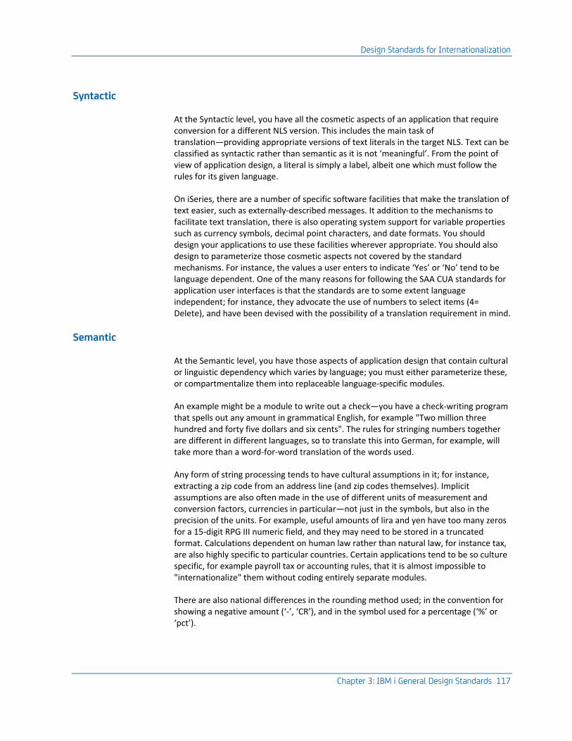
Design Standards for Internationalization
Chapter 3: IBM i General Design Standards 117
Syntactic
At the Syntactic level, you have all the cosmetic aspects of an application that require conversion for a different NLS version. This includes the main task of translation—providing appropriate versions of text literals in the target NLS. Text can be classified as syntactic rather than semantic as it is not ‘meaningful’. From the point of view of application design, a literal is simply a label, albeit one which must follow the rules for its given language.
On iSeries, there are a number of specific software facilities that make the translation of text easier, such as externally-described messages. It addition to the mechanisms to facilitate text translation, there is also operating system support for variable properties such as currency symbols, decimal point characters, and date formats. You should design your applications to use these facilities wherever appropriate. You should also design to parameterize those cosmetic aspects not covered by the standard mechanisms. For instance, the values a user enters to indicate ‘Yes’ or ‘No’ tend to be language dependent. One of the many reasons for following the SAA CUA standards for application user interfaces is that the standards are to some extent language independent; for instance, they advocate the use of numbers to select items (4= Delete), and have been devised with the possibility of a translation requirement in mind.
Semantic
At the Semantic level, you have those aspects of application design that contain cultural or linguistic dependency which varies by language; you must either parameterize these, or compartmentalize them into replaceable language-specific modules.
An example might be a module to write out a check—you have a check-writing program that spells out any amount in grammatical English, for example "Two million three hundred and forty five dollars and six cents". The rules for stringing numbers together are different in different languages, so to translate this into German, for example, will take more than a word-for-word translation of the words used.
Any form of string processing tends to have cultural assumptions in it; for instance, extracting a zip code from an address line (and zip codes themselves). Implicit assumptions are also often made in the use of different units of measurement and conversion factors, currencies in particular—not just in the symbols, but also in the precision of the units. For example, useful amounts of lira and yen have too many zeros for a 15-digit RPG III numeric field, and they may need to be stored in a truncated format. Calculations dependent on human law rather than natural law, for instance tax, are also highly specific to particular countries. Certain applications tend to be so culture specific, for example payroll tax or accounting rules, that it is almost impossible to "internationalize" them without coding entirely separate modules.
There are also national differences in the rounding method used; in the convention for showing a negative amount (‘-’, ‘CR’), and in the symbol used for a percentage (‘%’ or ‘pct’).
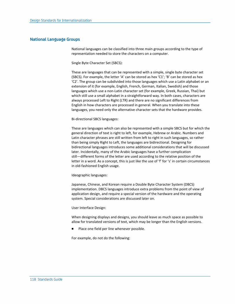
Design Standards for Internationalization
118 Standards Guide
National Language Groups
National languages can be classified into three main groups according to the type of representation needed to store the characters on a computer.
Single Byte Character Set (SBCS):
These are languages that can be represented with a simple, single byte character set (SBCS). For example, the letter ‘A’ can be stored as hex ‘C1’; ‘B’ can be stored as hex ‘C2’. The group can be subdivided into those languages which use a Latin alphabet or an extension of it (for example, English, French, German, Italian, Swedish) and those languages which use a non-Latin character set (for example, Greek, Russian, Thai) but which still use a small alphabet in a straightforward way. In both cases, characters are always processed Left to Right (LTR) and there are no significant differences from English in how characters are processed in general. When you translate into these languages, you need only the alternative character sets that the hardware provides.
Bi-directional SBCS languages:
These are languages which can also be represented with a simple SBCS but for which the general direction of text is right to left, for example, Hebrew or Arabic. Numbers and Latin character phrases are still written from left to right in such languages, so rather than being simply Right to Left, the languages are bidirectional. Designing for bidirectional languages introduces some additional considerations that will be discussed later. Incidentally, many of the Arabic languages have a further complication still—different forms of the letter are used according to the relative position of the letter in a word. As a concept, this is just like the use of ‘f’ for ‘s’ in certain circumstances in old-fashioned English usage.
Ideographic languages:
Japanese, Chinese, and Korean require a Double Byte Character System (DBCS) implementation. DBCS languages introduce extra problems from the point of view of application design, and require a special version of the hardware and the operating system. Special considerations are discussed later on.
User Interface Design:
When designing displays and designs, you should leave as much space as possible to allow for translated versions of text, which may be longer than the English versions.
■ Place one field per line whenever possible.
For example, do not do the following:
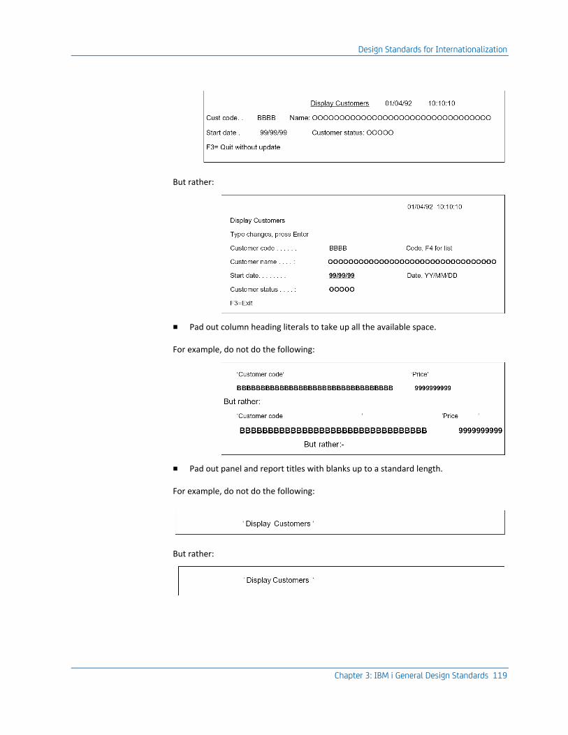
Design Standards for Internationalization
Chapter 3: IBM i General Design Standards 119
But rather:
■ Pad out column heading literals to take up all the available space.
For example, do not do the following:
■ Pad out panel and report titles with blanks up to a standard length.
For example, do not do the following:
But rather:
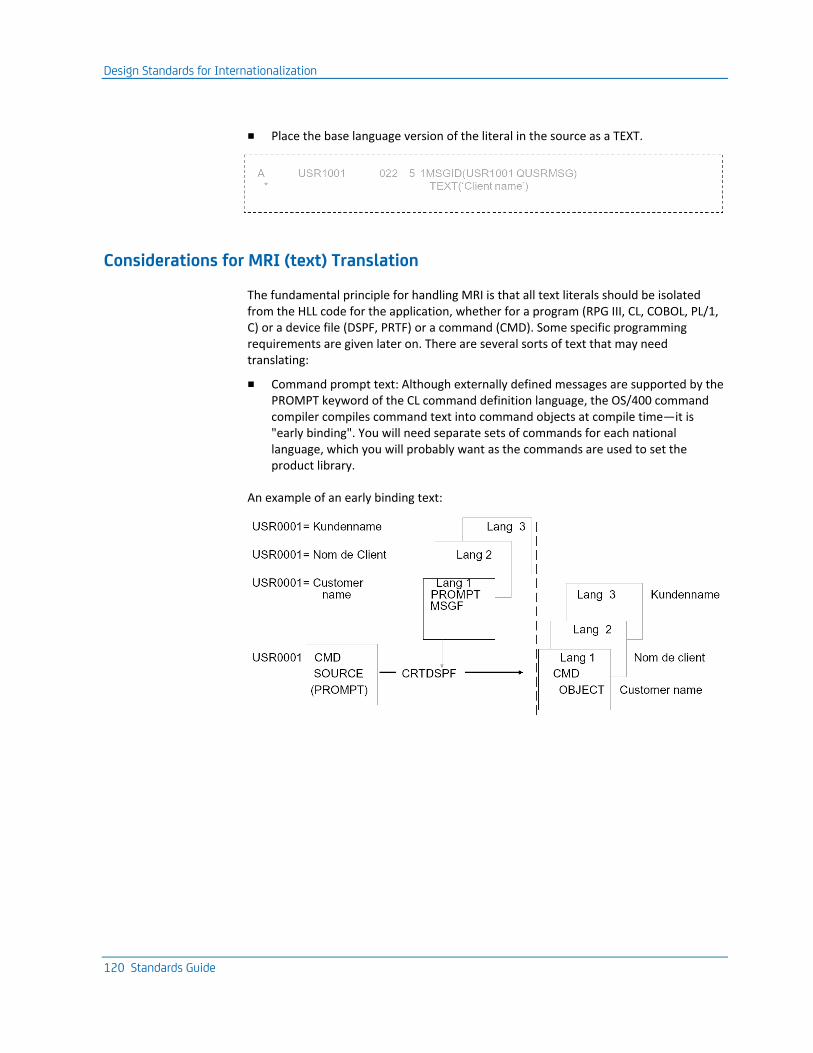
Design Standards for Internationalization
120 Standards Guide
■ Place the base language version of the literal in the source as a TEXT.
Considerations for MRI (text) Translation
The fundamental principle for handling MRI is that all text literals should be isolated from the HLL code for the application, whether for a program (RPG III, CL, COBOL, PL/1, C) or a device file (DSPF, PRTF) or a command (CMD). Some specific programming requirements are given later on. There are several sorts of text that may need translating:
■ Command prompt text: Although externally defined messages are supported by the PROMPT keyword of the CL command definition language, the OS/400 command compiler compiles command text into command objects at compile time—it is "early binding". You will need separate sets of commands for each national language, which you will probably want as the commands are used to set the product library.
An example of an early binding text:
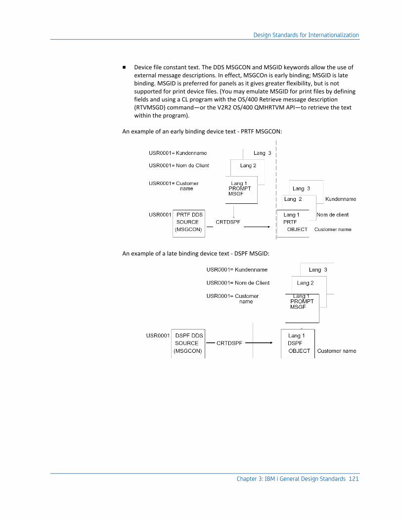
Design Standards for Internationalization
Chapter 3: IBM i General Design Standards 121
■ Device file constant text. The DDS MSGCON and MSGID keywords allow the use of external message descriptions. In effect, MSGCOn is early binding; MSGID is late binding. MSGID is preferred for panels as it gives greater flexibility, but is not supported for print device files. (You may emulate MSGID for print files by defining fields and using a CL program with the OS/400 Retrieve message description (RTVMSGD) command—or the V2R2 OS/400 QMHRTVM API—to retrieve the text within the program).
An example of an early binding device text - PRTF MSGCON:
An example of a late binding device text - DSPF MSGID:
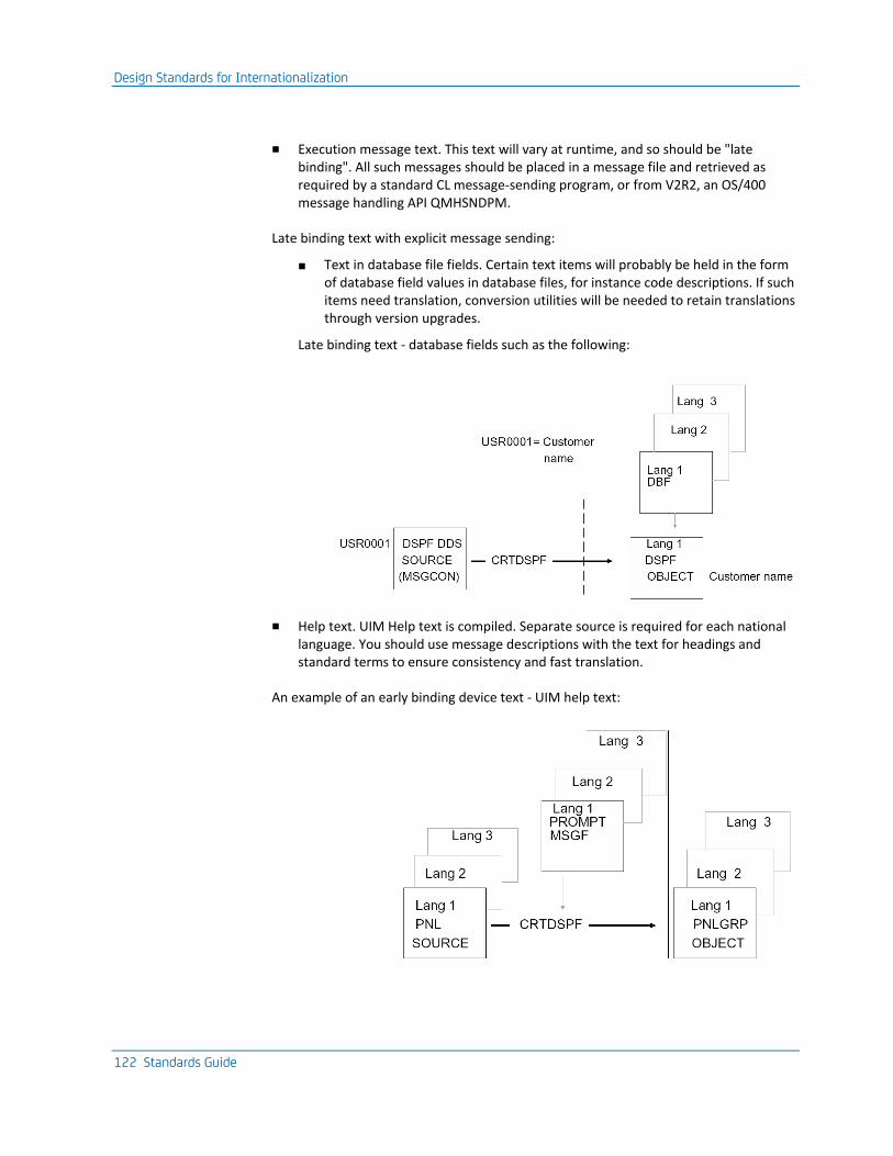
Design Standards for Internationalization
122 Standards Guide
■ Execution message text. This text will vary at runtime, and so should be "late binding". All such messages should be placed in a message file and retrieved as required by a standard CL message-sending program, or from V2R2, an OS/400 message handling API QMHSNDPM.
Late binding text with explicit message sending:
■ Text in database file fields. Certain text items will probably be held in the form of database field values in database files, for instance code descriptions. If such items need translation, conversion utilities will be needed to retain translations through version upgrades.
Late binding text - database fields such as the following:
■ Help text. UIM Help text is compiled. Separate source is required for each national language. You should use message descriptions with the text for headings and standard terms to ensure consistency and fast translation.
An example of an early binding device text - UIM help text:

Design Standards for Internationalization
Chapter 3: IBM i General Design Standards 123
Since help text is created automatically for programs generated with the CA 2E application generator, translating the application model and skeleton help text and regenerating is sufficient to translate end-user help text.
■ Menu text. On iSeries, menus are normally display files and can be treated as normal device files for the purposes of translation.
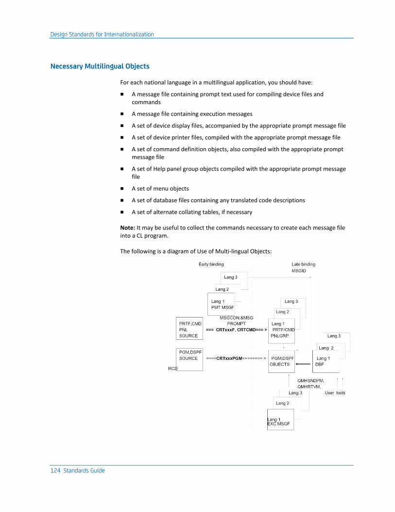
Design Standards for Internationalization
124 Standards Guide
Necessary Multilingual Objects
For each national language in a multilingual application, you should have:
■ A message file containing prompt text used for compiling device files and commands
■ A message file containing execution messages
■ A set of device display files, accompanied by the appropriate prompt message file
■ A set of device printer files, compiled with the appropriate prompt message file
■ A set of command definition objects, also compiled with the appropriate prompt message file
■ A set of Help panel group objects compiled with the appropriate prompt message file
■ A set of menu objects
■ A set of database files containing any translated code descriptions
■ A set of alternate collating tables, if necessary
Note: It may be useful to collect the commands necessary to create each message file into a CL program.
The following is a diagram of Use of Multi-lingual Objects:
Design Standards for Internationalization
Chapter 3: IBM i General Design Standards 125
Using System Values
OS/400 has several system values available, which can be used to help with internationalization. Store date fields on file in YMD format and convert them to local display format at execution, using the OS/400 QDATFMT and the QDATSEP system values.
For more information on date handling, see the chapter, "General Coding Standards."
You should normally use the system edit codes to edit monetary amounts so that the currency symbol shown is that specified by the OS/400 QCURSYM system value. If you carry out your own editing (for instance, to cater for variable decimal place fields), then you should retrieve the currency symbol from the QCURSYM system value.
Use the system edit codes to edit numeric fields so that the decimal point symbol shown is that specified by the OS/400 QDECFMT system value. If you carry out your own editing (for instance, to cater for variable decimal place fields), you should retrieve the decimal point symbol from the QDECFMT system value.
Use the QIGC system value to condition any special processing required if ideographic support is present. Equally, it can be used to condition special processing only available if ideographic support is not present. For example, there is no support for the DUP key on ideographic workstations.
Use non-alphabetic characters such as @, $, #, carefully, since they are not readily available in some multi-national character sets.
Note: For more information, refer to the information on the QCHRID OS/400 system value for further details.
Collating sequences in different alphabets may be slightly different especially for characters that are not found in the standard English alphabet. This may be significant in inquiry programs that show items in name order. If necessary, alternate collating tables should be used—this will require different sets of logical files in each language version.
Another system-supplied mechanism that can be useful is the translation table. This is a 256-byte table that can be used to control character mapping and usage in various circumstances, for instance in collating sequences, mapping of characters at devices, or translation within a program. Table objects are created from simple source members using the OS/400 Create Table (CRTTBL) command.
Tables can be especially effective when used in conjunction with the system supplied QDCXLATE program, which can be used to translate any character string, using a specified table.
Do not use compile time arrays to hold messages. If for performance reasons you need to hold messages in core storage (for example, because you send them many thousands of times in the course of a typical run), then you should load the messages from an external source at the beginning of the run.
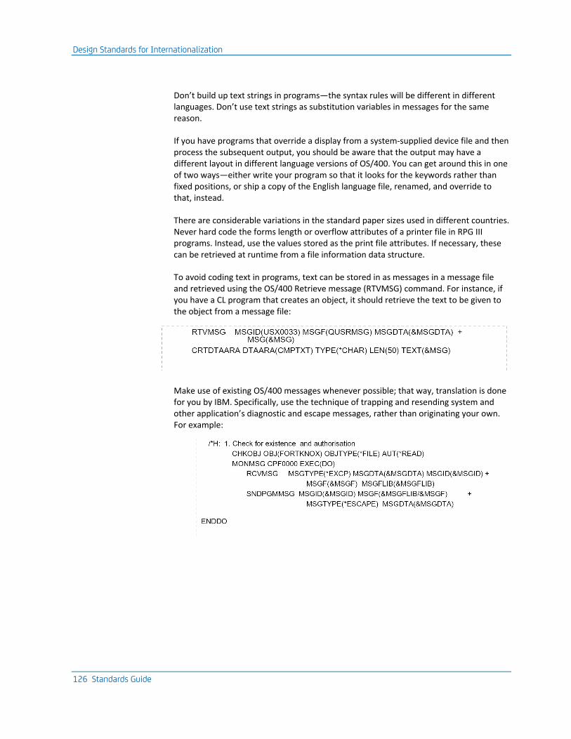
Design Standards for Internationalization
126 Standards Guide
Don’t build up text strings in programs—the syntax rules will be different in different languages. Don’t use text strings as substitution variables in messages for the same reason.
If you have programs that override a display from a system-supplied device file and then process the subsequent output, you should be aware that the output may have a different layout in different language versions of OS/400. You can get around this in one of two ways—either write your program so that it looks for the keywords rather than fixed positions, or ship a copy of the English language file, renamed, and override to that, instead.
There are considerable variations in the standard paper sizes used in different countries. Never hard code the forms length or overflow attributes of a printer file in RPG III programs. Instead, use the values stored as the print file attributes. If necessary, these can be retrieved at runtime from a file information data structure.
To avoid coding text in programs, text can be stored in as messages in a message file and retrieved using the OS/400 Retrieve message (RTVMSG) command. For instance, if you have a CL program that creates an object, it should retrieve the text to be given to the object from a message file:
Make use of existing OS/400 messages whenever possible; that way, translation is done for you by IBM. Specifically, use the technique of trapping and resending system and other application’s diagnostic and escape messages, rather than originating your own. For example:

Design Standards for Internationalization
Chapter 3: IBM i General Design Standards 127
Writing Text for Translation
Remember that translators are principally linguists—they may not necessarily be that familiar with either computer concepts, or with the concepts of your application domain. Usually, they will not be native English speakers. For those reasons, it is important that all text is worded as simply and as clearly as possible. There are a few stylistic principles you can follow in order to make your MRI clearer and therefore reduce the chances of a mis-translation.
For example:
■ Messages and other displayed phrases should be complete phrases and not be constructed from individual words or other phrases. Consider the following example. You have four different states to report: Terminal operational, Terminal offline, Control unit operational, and Control unit offline. One way of doing this would be to hold four short phrases (Terminal, Control unit, Operational, Offline) and to permutate them as required to build up messages. However, in French, this would not work because operational is declined (for example, takes a different suffix) according to gender—and control units are feminine. Thus, you need separate messages for Terminal operational and Unit de control operationelle.
■ Avoid abbreviations. For example, do not use Cust nm for customer name. Abbreviations generally do not appear in a dictionary and are hard for a non-native speaker to decipher. Avoid telegraphic style as it is hard to understand.
■ Avoid compound phrases. It can be very difficult to tell when the adjective stops and the verb starts, especially for a non-native speaker. For example, does Record error mean an error has occurred on a record (for example, adjective+verb) or does it mean Log the error somewhere? (for example, verb+noun). Likewise, would Program definition mean a definition of a program or definition by a program? It is better to be as explicit as possible even if it takes slightly more space.
■ Avoid negative questions. It is often not clear what the answer means or even what the question is; for example, ‘Do you not want to delete QSYS?’
■ Avoid slang, jargon, idiom and humor. It may be hard for the translator to find the terms in a dictionary, and the humor may be culture-specific.

Design Standards for Internationalization
128 Standards Guide
Ideographic Support
Some special considerations apply to the design of applications with ideographic support, such as is needed for Japanese versions.
For more information refer to the iSeries (AS/400) DDS Reference Guide.
It may be useful to know that the Japanese language has two separate phonetic alphabets, the Katakana and the Hiragana, as well as a system of ideographic characters, the Kanji. The Katakana alphabet is used for foreign loan words, such as computer terms. Thus, XX (obu-je-to) is object, YY (jo-bu) is job, etc. Hiragana is used for Japanese words; it is possible to spell out every Kanji character in a Hiragana equivalent.
The Katakana phonetic alphabet is handled on a computer in much the same way as is a language such as Greek—it is merely a different mapping of codes to graphic symbols. The Kanji ideograms, however, require additional facilities for implementation because there are so many of them. We can summarize further considerations under the following headings:
■ Using upper case
■ Double Byte Character Support
■ Using ideographic shifts
■ Providing ideographic conversion (IGCCNV)
■ Avoiding ideographic restrictions
Using Upper Case
Ideographic character (IGC) support requires a special version of OS/400 and special workstations. Ideographic workstations support upper case English characters, but not lower case ones. Any lower case characters may appear as semi-random garbage. This means that if you want to run your application on an ideographic workstation, even just in English, you should translate all characters in an application to upper case.
The system program QDCXLATE can be used in conjunction with the system-supplied translation tables (QSYSTRNTBL for the basic set, QCASE256 for the extended character set) to convert characters to their upper case equivalents. There are some CA 2E utilities to assist with this, in particular a tool to convert a database file data to upper case. The tool examines the database file object definition to find out which fields are alphanumeric. It also reads through the file, converting all such fields in all records to upper case (QCASE256 can be used). The same utility can be used to convert source members.
Files containing ideographic data that needs to be created or modified should have IGCDTA(*YES) specified for them.
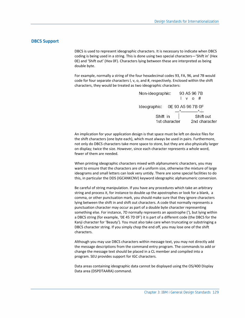
Design Standards for Internationalization
Chapter 3: IBM i General Design Standards 129
DBCS Support
DBCS is used to represent ideographic characters. It is necessary to indicate when DBCS coding is being used in a string. This is done using two special characters—‘Shift in’ (Hex 0E) and ‘Shift out’ (Hex 0F). Characters lying between these are interpreted as being double byte.
For example, normally a string of the four hexadecimal codes 93, FA, 96, and 7B would code for four separate characters l, v, o, and #, respectively. Enclosed within the shift characters, they would be treated as two ideographic characters:
An implication for your application design is that space must be left on device files for the shift characters (one byte each), which must always be used in pairs. Furthermore, not only do DBCS characters take more space to store, but they are also physically larger on display; twice the size. However, since each character represents a whole word, fewer of them are needed.
When printing ideographic characters mixed with alphanumeric characters, you may want to ensure that the characters are of a uniform size, otherwise the mixture of large ideograms and small letters can look very untidy. There are some special facilities to do this, in particular the DDS (IGCANKCNV) keyword ideographic alphanumeric conversion.
Be careful of string manipulation. If you have any procedures which take an arbitrary string and process it, for instance to double up the apostrophes or look for a blank, a comma, or other punctuation mark, you should make sure that they ignore characters lying between the shift in and shift out characters. A code that normally represents a punctuation character may occur as part of a double byte character representing something else. For instance, 7D normally represents an apostrophe (‘), but lying within a DBCS string (for example, ‘0E 45 7D 0F’) it is part of a different code (the DBCS for the Kanji character for ‘Beauty’). You must also take care when truncating or substringing a DBCS character string. If you simply chop the end off, you may lose one of the shift characters.
Although you may use DBCS characters within message text, you may not directly add the message descriptions from the command entry program. The commands to add or change the message text should be placed in a CL member and compiled into a program. SEU provides support for IGC characters.
Data areas containing ideographic data cannot be displayed using the OS/400 Display Data area (DSPDTAARA) command.
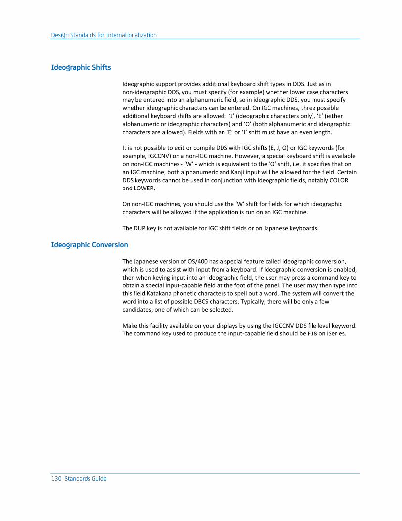
Design Standards for Internationalization
130 Standards Guide
Ideographic Shifts
Ideographic support provides additional keyboard shift types in DDS. Just as in non-ideographic DDS, you must specify (for example) whether lower case characters may be entered into an alphanumeric field, so in ideographic DDS, you must specify whether ideographic characters can be entered. On IGC machines, three possible additional keyboard shifts are allowed: ‘J’ (ideographic characters only), ‘E’ (either alphanumeric or ideographic characters) and ‘O’ (both alphanumeric and ideographic characters are allowed). Fields with an ‘E’ or ‘J’ shift must have an even length.
It is not possible to edit or compile DDS with IGC shifts (E, J, O) or IGC keywords (for example, IGCCNV) on a non-IGC machine. However, a special keyboard shift is available on non-IGC machines - ‘W’ - which is equivalent to the ‘O’ shift, i.e. it specifies that on an IGC machine, both alphanumeric and Kanji input will be allowed for the field. Certain DDS keywords cannot be used in conjunction with ideographic fields, notably COLOR and LOWER.
On non-IGC machines, you should use the ‘W’ shift for fields for which ideographic characters will be allowed if the application is run on an IGC machine.
The DUP key is not available for IGC shift fields or on Japanese keyboards.
Ideographic Conversion
The Japanese version of OS/400 has a special feature called ideographic conversion, which is used to assist with input from a keyboard. If ideographic conversion is enabled, then when keying input into an ideographic field, the user may press a command key to obtain a special input-capable field at the foot of the panel. The user may then type into this field Katakana phonetic characters to spell out a word. The system will convert the word into a list of possible DBCS characters. Typically, there will be only a few candidates, one of which can be selected.
Make this facility available on your displays by using the IGCCNV DDS file level keyword. The command key used to produce the input-capable field should be F18 on iSeries.
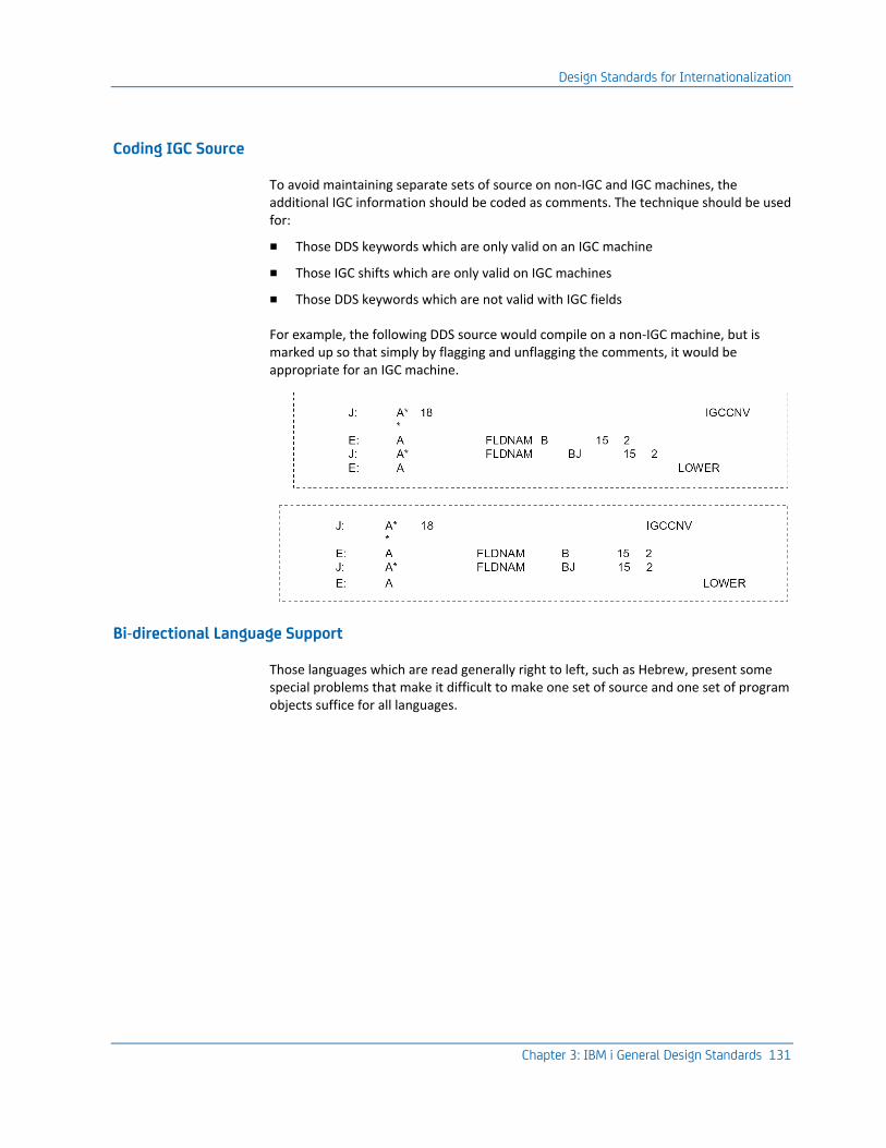
Design Standards for Internationalization
Chapter 3: IBM i General Design Standards 131
Coding IGC Source
To avoid maintaining separate sets of source on non-IGC and IGC machines, the additional IGC information should be coded as comments. The technique should be used for:
■ Those DDS keywords which are only valid on an IGC machine
■ Those IGC shifts which are only valid on IGC machines
■ Those DDS keywords which are not valid with IGC fields
For example, the following DDS source would compile on a non-IGC machine, but is marked up so that simply by flagging and unflagging the comments, it would be appropriate for an IGC machine.
Bi-directional Language Support
Those languages which are read generally right to left, such as Hebrew, present some special problems that make it difficult to make one set of source and one set of program objects suffice for all languages.
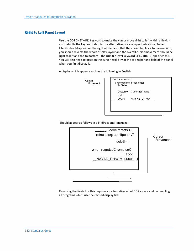
Design Standards for Internationalization
132 Standards Guide
Right to Left Panel Layout
Use the DDS CHECK(RL) keyword to make the cursor move right to left within a field. It also defaults the keyboard shift to the alternative (for example, Hebrew) alphabet. Literals should appear on the right of the fields that they describe. For a full conversion, you should reverse the whole display layout and the overall cursor movement should be right to left and top to bottom—the DDS file level keyword CHECK(RLTB) specifies this. You will also need to position the cursor explicitly at the top right hand field of the panel when you first display it.
A display which appears such as the following in English:
Should appear as follows in a bi-directional language:
Reversing the fields like this requires an alternative set of DDS source and recompiling all programs which use the revised display files.
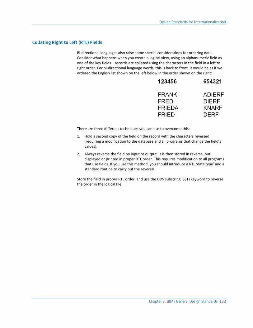
Design Standards for Internationalization
Chapter 3: IBM i General Design Standards 133
Collating Right to Left (RTL) Fields
Bi-directional languages also raise some special considerations for ordering data. Consider what happens when you create a logical view, using an alphanumeric field as one of the key fields—records are collated using the characters in the field in a left to right order. For bi-directional language words, this is back to front. It would be as if we ordered the English list shown on the left below in the order shown on the right:
There are three different techniques you can use to overcome this:
1. Hold a second copy of the field on the record with the characters reversed (requiring a modification to the database and all programs that change the field’s values).
2. Always reverse the field on input or output. It is then stored in reverse, but displayed or printed in proper RTL order. This requires modification to all programs that use fields. If you use this method, you should introduce a RTL ‘data type’ and a standard routine to carry out the reversal.
Store the field in proper RTL order, and use the DDS substring (SST) keyword to reverse the order in the logical file.

Chapter 4: General Coding Standards 135
Chapter 4: General Coding Standards
This chapter describes coding standards applicable to all source types.
This section contains the following topics:
Coding Principles (see page 135) Standard Source File Names (see page 136) Common Source File Coding Standards (see page 138) DDS Coding Standards for Files (see page 141) HLL Coding Standards for Programs (see page 141)
Coding Principles ■ Source code should contain all the information necessary to re-create the object.
This should include information about compile time overrides and object attributes.
■ Source code should be edited and viewed interactively as much as possible. Source listings should only actually be printed in special circumstances. Use the browsing and scanning facilities of the iSeries to examine source and compilation listings. Adopt layout conventions that facilitate this approach.
■ Use the machine to find syntax errors and basic mistakes. The editors and compilers of the iSeries give excellent diagnostics, and can be used to find low-level syntax errors.
■ Take an incremental approach to development. OS/400 provides an interactive development environment. Rather than writing and testing programs as entirely separate steps, you can program from top, down. Write the main control structure of a program first, compile and test it, and then add the detailed coding, such as field validation.
■ Strictly regulate source versions. One version of the source should be regarded as definitive. If changes are required, additional versions of the source should be copied to a separate development library and only be transferred back, together with the changed object, in a carefully controlled manner. For more information, refer to the section, Operating Environment Standards, in this guide.
■ Contain documentation within the source so that it is updated along with the code, and available when looking at the code. The documentation may be extracted and summarized using the CA 2E Toolkit Document Program (YDOCPGM) command.
The CA 2E Toolkit Compile pre-processor utility provides several useful functions common to all source types, including compiler overrides. See the Toolkit Concepts Guide for further details.
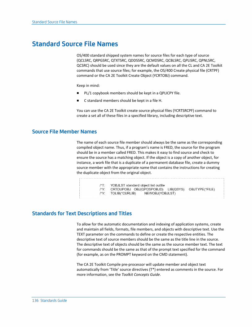
Standard Source File Names
136 Standards Guide
Standard Source File Names
OS/400 standard shipped system names for source files for each type of source (QCLSRC, QRPGSRC, QTXTSRC, QDDSSRC, QCMDSRC, QCBLSRC, QPLISRC, QPNLSRC, QCSRC) should be used since they are the default values on all the CL and CA 2E Toolkit commands that use source files; for example, the OS/400 Create physical file (CRTPF) command or the CA 2E Toolkit Create Object (YCRTOBJ) command.
Keep in mind:
■ PL/1 copybook members should be kept in a QPLICPY file.
■ C standard members should be kept in a file H.
You can use the CA 2E Toolkit create source physical files (YCRTSRCPF) command to create a set all of these files in a specified library, including descriptive text.
Source File Member Names
The name of each source file member should always be the same as the corresponding compiled object name. Thus, if a program’s name is FRED, the source for the program should be in a member called FRED. This makes it easy to find source and check to ensure the source has a matching object. If the object is a copy of another object, for instance, a work file that is a duplicate of a permanent database file, create a dummy source member with the appropriate name that contains the instructions for creating the duplicate object from the original object.
Standards for Text Descriptions and Titles
To allow for the automatic documentation and indexing of application systems, create and maintain all fields, formats, file members, and objects with descriptive text. Use the TEXT parameter on the commands to define or create the respective entities. The descriptive text of source members should be the same as the title line in the source. The descriptive text of objects should be the same as the source member text. The text for commands should be the same as that of the prompt text specified for the command (for example, as on the PROMPT keyword on the CMD statement).
The CA 2E Toolkit Compile pre-processor will update member and object text automatically from ‘Title’ source directives (T*) entered as comments in the source. For more information, see the Toolkit Concepts Guide.
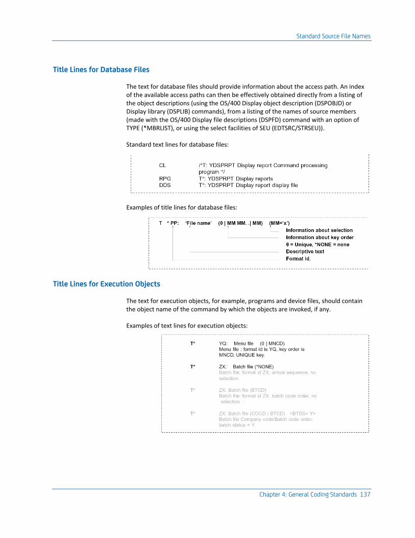
Standard Source File Names
Chapter 4: General Coding Standards 137
Title Lines for Database Files
The text for database files should provide information about the access path. An index of the available access paths can then be effectively obtained directly from a listing of the object descriptions (using the OS/400 Display object description (DSPOBJD) or Display library (DSPLIB) commands), from a listing of the names of source members (made with the OS/400 Display file descriptions (DSPFD) command with an option of TYPE (*MBRLIST), or using the select facilities of SEU (EDTSRC/STRSEU)).
Standard text lines for database files:
Examples of title lines for database files:
Title Lines for Execution Objects
The text for execution objects, for example, programs and device files, should contain the object name of the command by which the objects are invoked, if any.
Examples of text lines for execution objects:
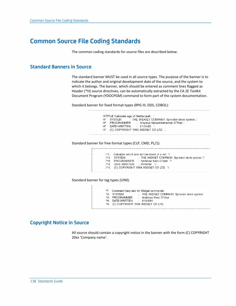
Common Source File Coding Standards
138 Standards Guide
Common Source File Coding Standards
The common coding standards for source files are described below.
Standard Banners in Source
The standard banner MUST be used in all source types. The purpose of the banner is to indicate the author and original development date of the source, and the system to which it belongs. The banner, which should be entered as comment lines flagged as Header (*H) source directives, can be automatically extracted by the CA 2E Toolkit Document Program (YDOCPGM) command to form part of the system documentation.
Standard banner for fixed format types (RPG III, DDS, COBOL):
Standard banner for free format types (CLP, CMD, PL/1):
Standard banner for tag types (UIM):
Copyright Notice in Source
All source should contain a copyright notice in the banner with the form (C) COPYRIGHT 20xx ‘Company name’.
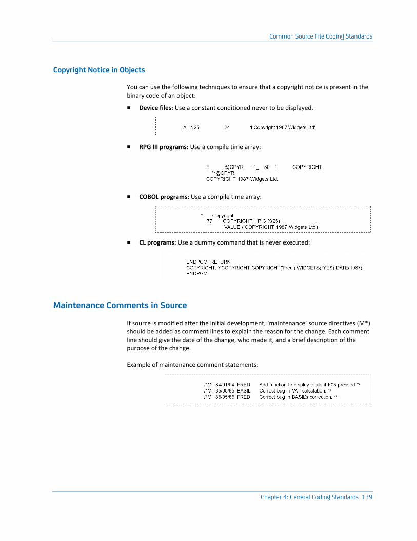
Common Source File Coding Standards
Chapter 4: General Coding Standards 139
Copyright Notice in Objects
You can use the following techniques to ensure that a copyright notice is present in the binary code of an object:
■ Device files: Use a constant conditioned never to be displayed.
■ RPG III programs: Use a compile time array:
■ COBOL programs: Use a compile time array:
■ CL programs: Use a dummy command that is never executed:
Maintenance Comments in Source
If source is modified after the initial development, ‘maintenance’ source directives (M*) should be added as comment lines to explain the reason for the change. Each comment line should give the date of the change, who made it, and a brief description of the purpose of the change.
Example of maintenance comment statements:
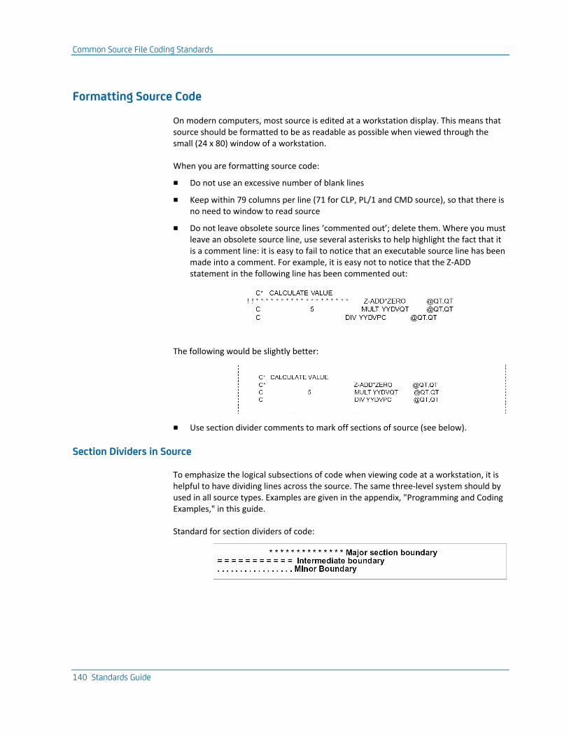
Common Source File Coding Standards
140 Standards Guide
Formatting Source Code
On modern computers, most source is edited at a workstation display. This means that source should be formatted to be as readable as possible when viewed through the small (24 x 80) window of a workstation.
When you are formatting source code:
■ Do not use an excessive number of blank lines
■ Keep within 79 columns per line (71 for CLP, PL/1 and CMD source), so that there is no need to window to read source
■ Do not leave obsolete source lines ‘commented out’; delete them. Where you must leave an obsolete source line, use several asterisks to help highlight the fact that it is a comment line: it is easy to fail to notice that an executable source line has been made into a comment. For example, it is easy not to notice that the Z-ADD statement in the following line has been commented out:
The following would be slightly better:
■ Use section divider comments to mark off sections of source (see below).
Section Dividers in Source
To emphasize the logical subsections of code when viewing code at a workstation, it is helpful to have dividing lines across the source. The same three-level system should by used in all source types. Examples are given in the appendix, "Programming and Coding Examples," in this guide.
Standard for section dividers of code:
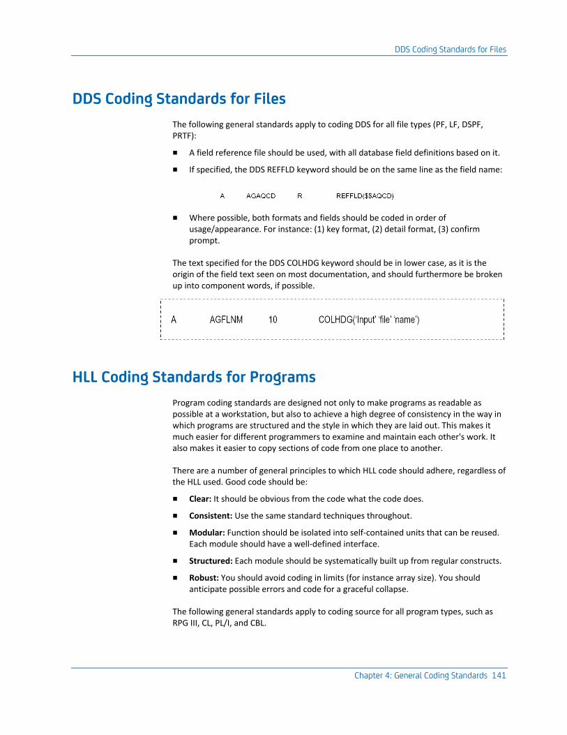
DDS Coding Standards for Files
Chapter 4: General Coding Standards 141
DDS Coding Standards for Files
The following general standards apply to coding DDS for all file types (PF, LF, DSPF, PRTF):
■ A field reference file should be used, with all database field definitions based on it.
■ If specified, the DDS REFFLD keyword should be on the same line as the field name:
■ Where possible, both formats and fields should be coded in order of usage/appearance. For instance: (1) key format, (2) detail format, (3) confirm prompt.
The text specified for the DDS COLHDG keyword should be in lower case, as it is the origin of the field text seen on most documentation, and should furthermore be broken up into component words, if possible.
HLL Coding Standards for Programs
Program coding standards are designed not only to make programs as readable as possible at a workstation, but also to achieve a high degree of consistency in the way in which programs are structured and the style in which they are laid out. This makes it much easier for different programmers to examine and maintain each other's work. It also makes it easier to copy sections of code from one place to another.
There are a number of general principles to which HLL code should adhere, regardless of the HLL used. Good code should be:
■ Clear: It should be obvious from the code what the code does.
■ Consistent: Use the same standard techniques throughout.
■ Modular: Function should be isolated into self-contained units that can be reused. Each module should have a well-defined interface.
■ Structured: Each module should be systematically built up from regular constructs.
■ Robust: You should avoid coding in limits (for instance array size). You should anticipate possible errors and code for a graceful collapse.
The following general standards apply to coding source for all program types, such as RPG III, CL, PL/I, and CBL.
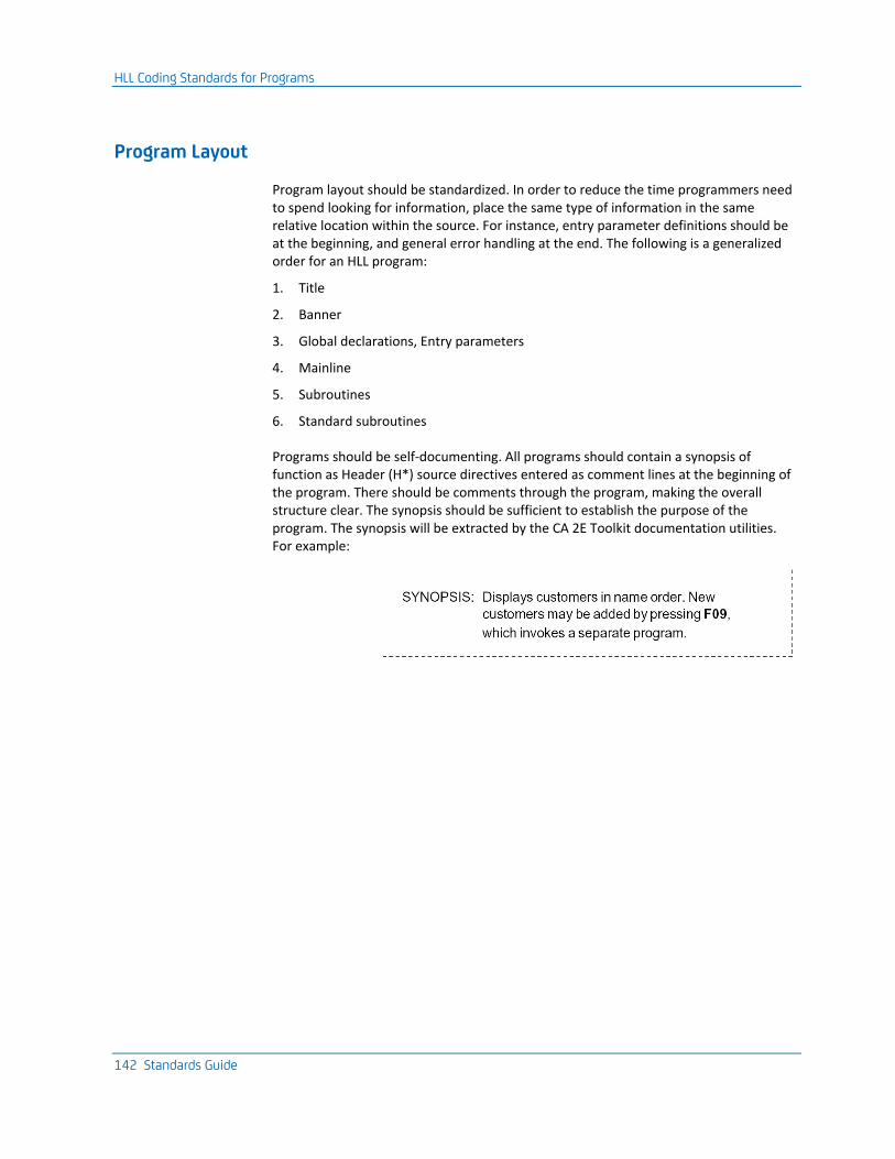
HLL Coding Standards for Programs
142 Standards Guide
Program Layout
Program layout should be standardized. In order to reduce the time programmers need to spend looking for information, place the same type of information in the same relative location within the source. For instance, entry parameter definitions should be at the beginning, and general error handling at the end. The following is a generalized order for an HLL program:
1. Title
2. Banner
3. Global declarations, Entry parameters
4. Mainline
5. Subroutines
6. Standard subroutines
Programs should be self-documenting. All programs should contain a synopsis of function as Header (H*) source directives entered as comment lines at the beginning of the program. There should be comments through the program, making the overall structure clear. The synopsis should be sufficient to establish the purpose of the program. The synopsis will be extracted by the CA 2E Toolkit documentation utilities. For example:
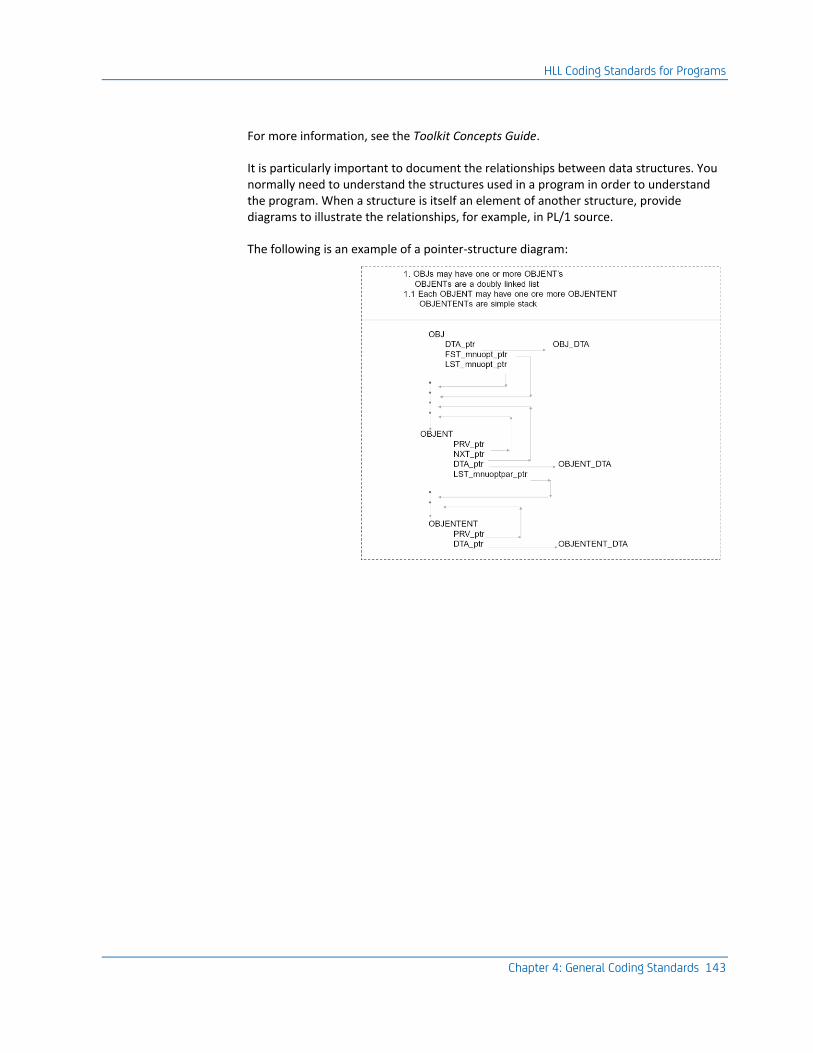
HLL Coding Standards for Programs
Chapter 4: General Coding Standards 143
For more information, see the Toolkit Concepts Guide.
It is particularly important to document the relationships between data structures. You normally need to understand the structures used in a program in order to understand the program. When a structure is itself an element of another structure, provide diagrams to illustrate the relationships, for example, in PL/1 source.
The following is an example of a pointer-structure diagram:
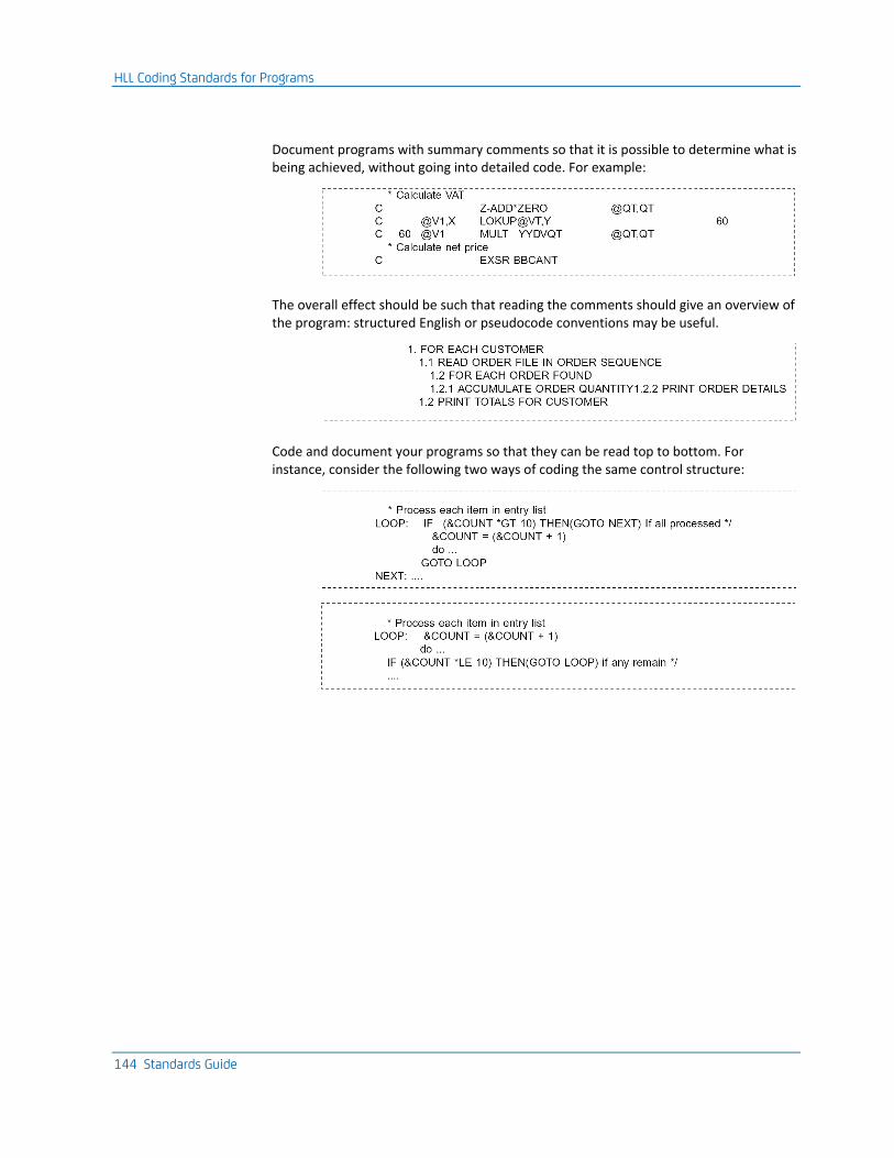
HLL Coding Standards for Programs
144 Standards Guide
Document programs with summary comments so that it is possible to determine what is being achieved, without going into detailed code. For example:
The overall effect should be such that reading the comments should give an overview of the program: structured English or pseudocode conventions may be useful.
Code and document your programs so that they can be read top to bottom. For instance, consider the following two ways of coding the same control structure:
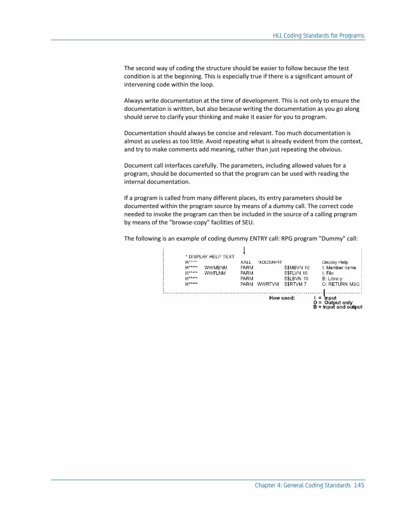
HLL Coding Standards for Programs
Chapter 4: General Coding Standards 145
The second way of coding the structure should be easier to follow because the test condition is at the beginning. This is especially true if there is a significant amount of intervening code within the loop.
Always write documentation at the time of development. This is not only to ensure the documentation is written, but also because writing the documentation as you go along should serve to clarify your thinking and make it easier for you to program.
Documentation should always be concise and relevant. Too much documentation is almost as useless as too little. Avoid repeating what is already evident from the context, and try to make comments add meaning, rather than just repeating the obvious.
Document call interfaces carefully. The parameters, including allowed values for a program, should be documented so that the program can be used with reading the internal documentation.
If a program is called from many different places, its entry parameters should be documented within the program source by means of a dummy call. The correct code needed to invoke the program can then be included in the source of a calling program by means of the "browse-copy" facilities of SEU.
The following is an example of coding dummy ENTRY call: RPG program "Dummy" call:
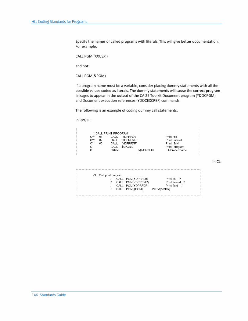
HLL Coding Standards for Programs
146 Standards Guide
Specify the names of called programs with literals. This will give better documentation. For example,
CALL PGM(‘XXUSX’)
and not:
CALL PGM(&PGM)
If a program name must be a variable, consider placing dummy statements with all the possible values coded as literals. The dummy statements will cause the correct program linkages to appear in the output of the CA 2E Toolkit Document program (YDOCPGM) and Document execution references (YDOCEXCREF) commands.
The following is an example of coding dummy call statements.
In RPG III:
In CL:
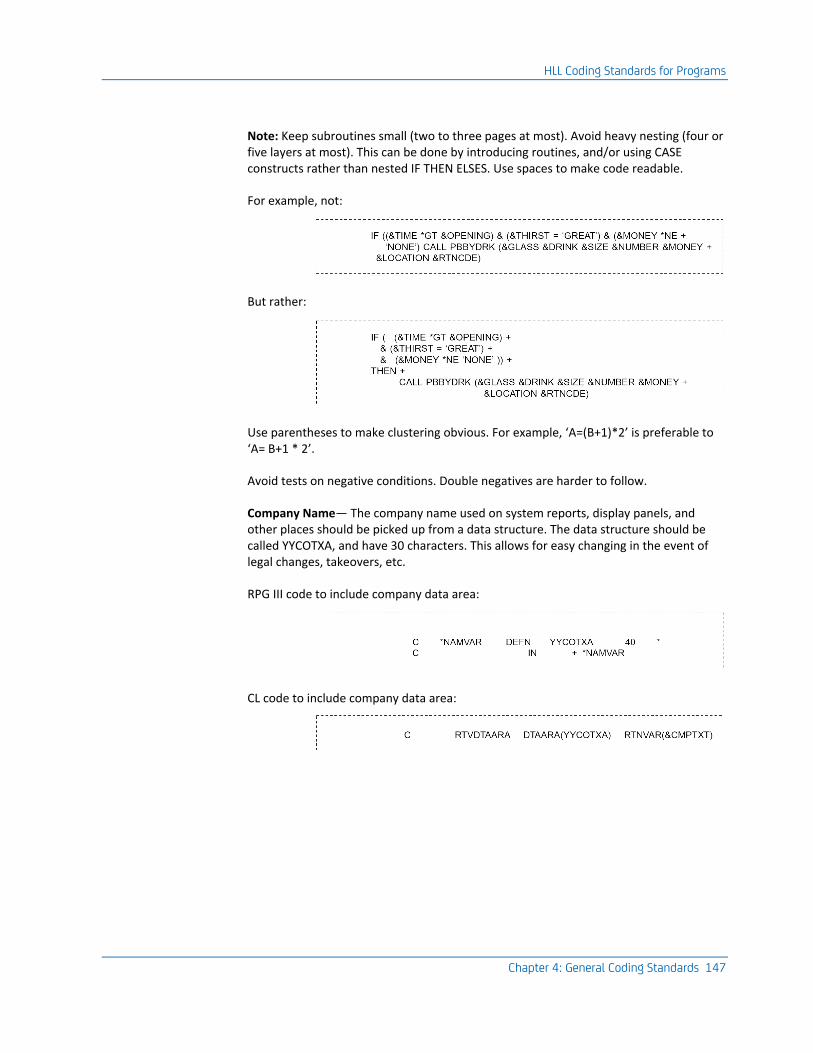
HLL Coding Standards for Programs
Chapter 4: General Coding Standards 147
Note: Keep subroutines small (two to three pages at most). Avoid heavy nesting (four or five layers at most). This can be done by introducing routines, and/or using CASE constructs rather than nested IF THEN ELSES. Use spaces to make code readable.
For example, not:
But rather:
Use parentheses to make clustering obvious. For example, ‘A=(B+1)*2’ is preferable to ‘A= B+1 * 2’.
Avoid tests on negative conditions. Double negatives are harder to follow.
Company Name— The company name used on system reports, display panels, and other places should be picked up from a data structure. The data structure should be called YYCOTXA, and have 30 characters. This allows for easy changing in the event of legal changes, takeovers, etc.
RPG III code to include company data area:
CL code to include company data area:
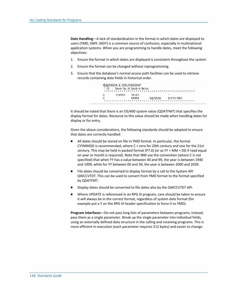
HLL Coding Standards for Programs
148 Standards Guide
Date Handling—A lack of standardization in the format in which dates are displayed to users (YMD, DMY, MDY) is a common source of confusion, especially in multinational application systems. When you are programming to handle dates, meet the following objectives:
1. Ensure the format in which dates are displayed is consistent throughout the system
2. Ensure the format can be changed without reprogramming.
3. Ensure that the database’s normal access path facilities can be used to retrieve records containing date fields in historical order.
It should be noted that there is an OS/400 system value (QDATFMT) that specifies the display format for dates. Recourse to this value should be made when handling dates for display or for entry.
Given the above considerations, the following standards should be adopted to ensure that dates are correctly handled:
■ All dates should be stored on file in YMD format. In particular, the format CYYMMDD is recommended, where C = zero for 20th century and one for the 21st century. This may be held in packed format (P7.0) (or as YY + MM + DD if read equal on year or month is required). Note that IBM use the convention (where C is not specified) that when YY has a value between 40 and 99, the year is between 1940 and 1999, while for YY between 00 and 39, the year is between 2000 and 2039.
■ File dates should be converted to display format by a call to the System API QWCCVTDT. This can be used to convert from YMD format to the format specified by QDATFMT.
■ Display dates should be converted to file dates also by the QWCCVTDT API.
■ Where UPDATE is referenced in an RPG III program, care should be taken to ensure it will always be in the correct format, regardless of system date format (for example put a Y on the RPG III header specification to force it to YMD).
Program Interfaces—Do not pass long lists of parameters between programs; instead, pass them as a single parameter. Break up the single parameter into individual fields, using an externally defined data structure in the calling and receiving programs. This is more efficient in execution (each parameter requires 512 bytes) and easier to change.

HLL Coding Standards for Programs
Chapter 4: General Coding Standards 149
Coding for iSeries
If you have a requirement to maintain versions of the same application on iSeries, you should code to accommodate this requirement.
For this you will need to:
■ Avoid using machine specific features (for example native iSeries CL syntax)
■ Parameterize or develop automatic conversion techniques for those aspects of the application which should be different on each machine (for example, command key usage)
In general, it is easy to code DDS, RPG III and command source to be compatible on either machine, even in native mode. CL is more problematic. Most of the considerations are given in the IBM ‘Migration Manual’. The following specific tips may be useful.
DDS—Do not qualify names that appear in DDS, for instance with the DDS REF, PRINT, or MSGCON keywords. Do not even use *LIBL as the qualifier value.
Be consistent in your use of the following panel components:
■ Command keys (for example, use F03 for Exit on iSeries)
■ Command key explanations (for example, ‘F3=Exit F5=Refresh’ on iSeries)
■ Field leader characters (for example, ‘Customer . . :’ on iSeries)
RPG III—There are no significant constraints on coding RPG III so that it can be run on either machine. If you need to execute request strings dynamically, use QCAEXEC (which is present on both machines) rather than QCMDEXC, the iSeries native program.
Commands—Because of the slight differences between the OS/400 and CPF versions of CL, it is not always possible to design commands that are 100% compatible with both OS/400 and CPF.
For commands where such differences occur, you should:
■ Design a common command processing program
■ Create an alternative version of the command, following iSeries conventions
Coding CL—You may use the presence or absence of the data area Q5728SS1 in QSYS to determine whether or not you are on iSeries (it only exists on iSeries). The result can be used to condition subsequent processing.


Chapter 5: Coding Standards for Database Files 151
Chapter 5: Coding Standards for Database Files
This chapter describes coding standards for database files. It details standards for coding both field reference files and physical and logical files.
Note: Each application system should have a single field reference file, containing definitions for all the fields in all the database files.
For more information on examples of the standards, refer to the appendix, "Programming and Coding Examples".
This section contains the following topics:
Data Dictionary/Field Reference File (see page 152) Physical and Logical Database Files (see page 155) Coding Standards for Display Files (see page 157) Coding Standards for Printer Files (see page 164) Coding Standards for HLL Programs (see page 169) Coding Standards for CL Programs (see page 169) Coding Standards for RPG III Programs (see page 173) Coding Standards for COBOL Programs (see page 190) Coding Standards for PL/1 Programs (see page 203) PL/1 Coding Structures and Program Logic (see page 211) Command Coding Conventions (see page 219) Coding Standards for Messages (see page 226) Standards for Defining Messages (see page 232) Coding Standards for Help Text (see page 238)
Data Dictionary/Field Reference File
152 Standards Guide
Data Dictionary/Field Reference File
A data dictionary is a centralized repository of field and data definitions. It is intended to:
■ Facilitate documentation—all definitions are in only one place
■ Minimize coding—definitions need to be coded only once
■ Facilitate change—definitions need be changed in only one place
The function of the data dictionary may be achieved effectively on the IBM i by having a special physical file containing no data. Such a file is generally known as a field reference file.
CA 2E can automatically generate a field reference file. However, since each CA 2E model is effectively a data dictionary, you will probably only wish to have CA 2E generate a field reference file if the generated applications will be running on a machine that does not have CA 2E installed. CA 2E has a model value YFRFVNM, which controls whether the code generated by CA 2E for files refers to a field reference file or not.
Standard for Field Reference Files
The following standard applies to field reference files:
■ If you are using the CA 2E systematic convention, always call the file ssFDRFP, where ss is the System prefix and contains a single format called @FDRF$$.
■ The file should be structured into two parts: primary fields and secondary fields. Refer to the appendix, "Programming and Coding Examples," for examples.
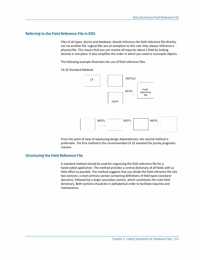
Data Dictionary/Field Reference File
Chapter 5: Coding Standards for Database Files 153
Referring to the Field Reference File in DDS
Files of all types, device and database, should reference the field reference file directly, not via another file. Logical files are an exception to this rule: they always reference a physical file. This means that you can resolve all inquiries about a field by looking directly in one place. It also simplifies the order in which you need to recompile objects.
The following example illustrates the use of field reference files.
CA 2E Standard Method:
From the point of view of expressing design dependencies, the second method is preferable. The first method is the recommended CA 2E standard for purely pragmatic reasons.
Structuring the Field Reference File
A standard method should be used for organizing the field reference file for a hand-coded application. The method provides a central dictionary of all fields with as little effort as possible. The method suggests that you divide the field reference file into two sections: a short primary section containing definitions of field types (standard domains), followed by a larger secondary section, which constitutes the main field dictionary. Both sections should be in alphabetical order to facilitate inquiries and maintenance.
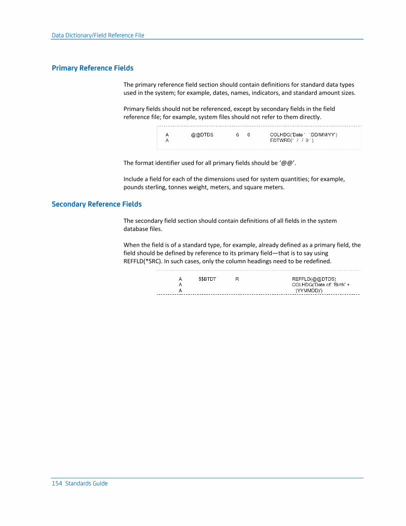
Data Dictionary/Field Reference File
154 Standards Guide
Primary Reference Fields
The primary reference field section should contain definitions for standard data types used in the system; for example, dates, names, indicators, and standard amount sizes.
Primary fields should not be referenced, except by secondary fields in the field reference file; for example, system files should not refer to them directly.
The format identifier used for all primary fields should be ‘@@’.
Include a field for each of the dimensions used for system quantities; for example, pounds sterling, tonnes weight, meters, and square meters.
Secondary Reference Fields
The secondary field section should contain definitions of all fields in the system database files.
When the field is of a standard type, for example, already defined as a primary field, the field should be defined by reference to its primary field—that is to say using REFFLD(*SRC). In such cases, only the column headings need to be redefined.
Physical and Logical Database Files
Chapter 5: Coding Standards for Database Files 155
Fields should only be defined with reference to a type field when there is a genuine dependence. A simple test of this is to ask the question: If I were to change the definition of the based-on field, would I want the definition of the dependent field to change as well?
When appropriate (for example, for total fields) use relative lengths (+-)n to increase or decrease field lengths with respect to the based-on field.
Each field should be fully defined with edit codes/words, text, ranges, values, display attributes, etc. Use the DDS COLHDG keyword rather than the TEXT keyword as it provides neater documentation.
Note: It is important that definitions are as full as possible, as they constitute the central reference information for the whole database.
The format identifier for all secondary reference fields should be ‘$$’. (This may be controlled in CA 2E generated databases by the YFRFPFX model value.)
Fields should be in alphabetical order within the section. They should be indexed by mnemonic. This provides a self-updating list of the mnemonics that have been used.
Physical and Logical Database Files
This section describes coding standards for database files. See the appendix, "Programming and Coding Examples", for examples.
Database File Coding Standards: File Level
Use level checking on files in order to detect errors arising from changes to the database definition—for example, specify LVLCHK(*YES) on the OS/400 CRTPF and CRTLF commands.
Create files that will continue to grow with SIZE(*NOMAX). Use the CA 2E Toolkit Compile preprocessor to do this automatically every time you recompile.
Format Level
The names of formats in logical files should be the same as for the format in the underlying physical file, with the number of the particular logical view appended, if necessary.
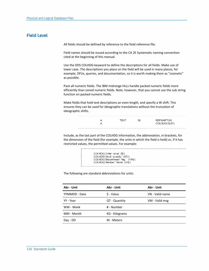
Physical and Logical Database Files
156 Standards Guide
Field Level
All fields should be defined by reference to the field reference file.
Field names should be issued according to the CA 2E Systematic naming convention cited at the beginning of this manual.
Use the DDS COLHDG keyword to define the descriptions for all fields. Make use of lower case. The descriptions you place on the field will be used in many places; for example, DFUs, queries, and documentation, so it is worth making them as "cosmetic" as possible.
Pack all numeric fields. The IBM midrange HLLs handle packed numeric fields more efficiently than zoned numeric fields. Note, however, that you cannot use the sub string function on packed numeric fields.
Make fields that hold text descriptions an even length, and specify a W shift. This ensures they can be used for ideographic translations without the truncation of ideographic shifts.
Include, as the last part of the COLHDG information, the abbreviation, in brackets, for the dimension of the field (for example, the units in which the field is held) or, if it has restricted values, the permitted values. For example:
The following are standard abbreviations for units:
Abr - Unit Abr - Unit Abr - Unit
YYMMDD - Date $ - Value VN - Valid name
YY - Year QT - Quantity VM - Valid msg
WW - Week # - Number
MM - Month KG - Kilograms
Day - DD M - Meters
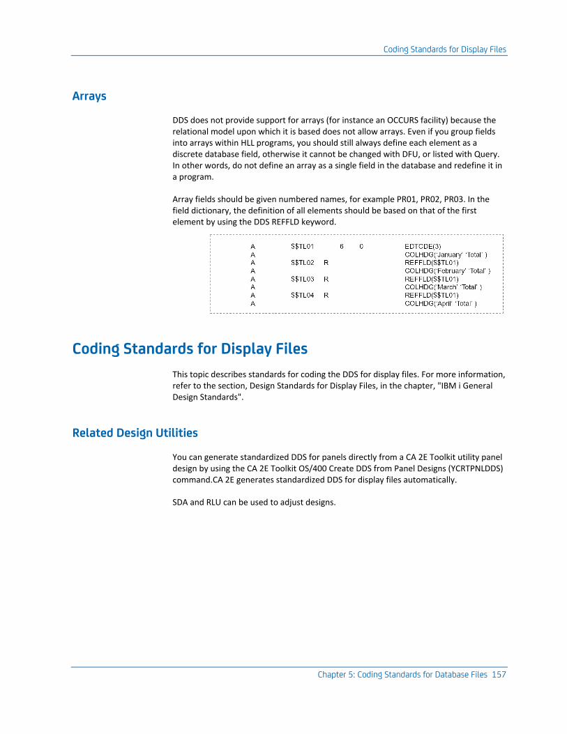
Coding Standards for Display Files
Chapter 5: Coding Standards for Database Files 157
Arrays
DDS does not provide support for arrays (for instance an OCCURS facility) because the relational model upon which it is based does not allow arrays. Even if you group fields into arrays within HLL programs, you should still always define each element as a discrete database field, otherwise it cannot be changed with DFU, or listed with Query. In other words, do not define an array as a single field in the database and redefine it in a program.
Array fields should be given numbered names, for example PR01, PR02, PR03. In the field dictionary, the definition of all elements should be based on that of the first element by using the DDS REFFLD keyword.
Coding Standards for Display Files
This topic describes standards for coding the DDS for display files. For more information, refer to the section, Design Standards for Display Files, in the chapter, "IBM i General Design Standards".
Related Design Utilities
You can generate standardized DDS for panels directly from a CA 2E Toolkit utility panel design by using the CA 2E Toolkit OS/400 Create DDS from Panel Designs (YCRTPNLDDS) command.CA 2E generates standardized DDS for display files automatically.
SDA and RLU can be used to adjust designs.
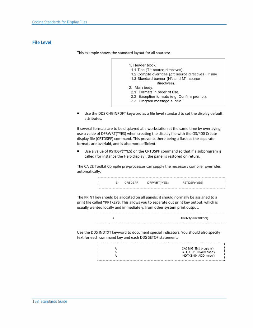
Coding Standards for Display Files
158 Standards Guide
File Level
This example shows the standard layout for all sources:
■ Use the DDS CHGINPDFT keyword as a file level standard to set the display default attributes.
If several formats are to be displayed at a workstation at the same time by overlaying, use a value of DFRWRT(*YES) when creating the display file with the OS/400 Create display file (CRTDSPF) command. This prevents there being a flash as the separate formats are overlaid, and is also more efficient.
■ Use a value of RSTDSP(*YES) on the CRTDSPF command so that if a subprogram is called (for instance the Help display), the panel is restored on return.
The CA 2E Toolkit Compile pre-processor can supply the necessary compiler overrides automatically:
The PRINT key should be allocated on all panels: it should normally be assigned to a print file called YPRTKEY$. This allows you to separate out print key output, which is usually wanted locally and immediately, from other system print output.
Use the DDS INDTXT keyword to document special indicators. You should also specify text for each command key and each DDS SETOF statement.
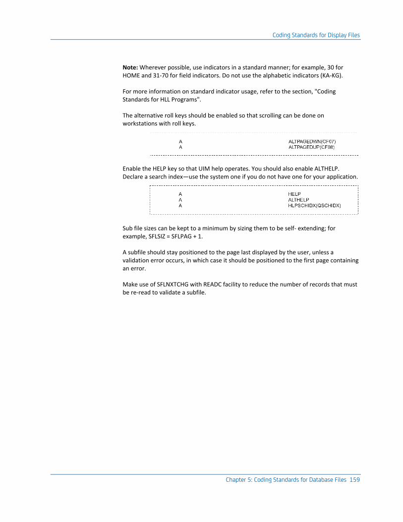
Coding Standards for Display Files
Chapter 5: Coding Standards for Database Files 159
Note: Wherever possible, use indicators in a standard manner; for example, 30 for HOME and 31-70 for field indicators. Do not use the alphabetic indicators (KA-KG).
For more information on standard indicator usage, refer to the section, "Coding Standards for HLL Programs".
The alternative roll keys should be enabled so that scrolling can be done on workstations with roll keys.
Enable the HELP key so that UIM help operates. You should also enable ALTHELP. Declare a search index—use the system one if you do not have one for your application.
Sub file sizes can be kept to a minimum by sizing them to be self- extending; for example, SFLSIZ = SFLPAG + 1.
A subfile should stay positioned to the page last displayed by the user, unless a validation error occurs, in which case it should be positioned to the first page containing an error.
Make use of SFLNXTCHG with READC facility to reduce the number of records that must be re-read to validate a subfile.
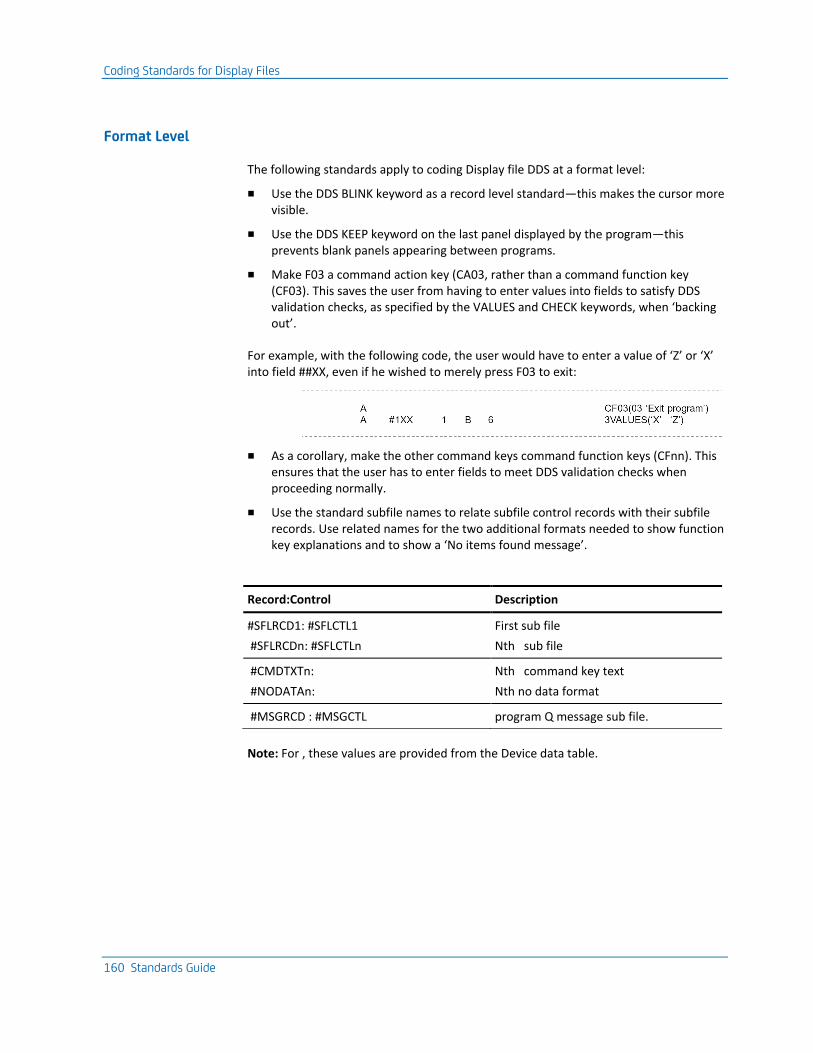
Coding Standards for Display Files
160 Standards Guide
Format Level
The following standards apply to coding Display file DDS at a format level:
■ Use the DDS BLINK keyword as a record level standard—this makes the cursor more visible.
■ Use the DDS KEEP keyword on the last panel displayed by the program—this prevents blank panels appearing between programs.
■ Make F03 a command action key (CA03, rather than a command function key (CF03). This saves the user from having to enter values into fields to satisfy DDS validation checks, as specified by the VALUES and CHECK keywords, when ‘backing out’.
For example, with the following code, the user would have to enter a value of ‘Z’ or ‘X’ into field ##XX, even if he wished to merely press F03 to exit:
■ As a corollary, make the other command keys command function keys (CFnn). This ensures that the user has to enter fields to meet DDS validation checks when proceeding normally.
■ Use the standard subfile names to relate subfile control records with their subfile records. Use related names for the two additional formats needed to show function key explanations and to show a ‘No items found message’.
Record:Control Description
#SFLRCD1: #SFLCTL1
#SFLRCDn: #SFLCTLn
First sub file
Nth sub file
#CMDTXTn:
#NODATAn:
Nth command key text
Nth no data format
#MSGRCD : #MSGCTL program Q message sub file.
Note: For , these values are provided from the Device data table.
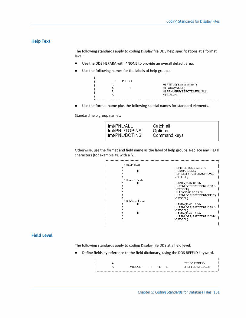
Coding Standards for Display Files
Chapter 5: Coding Standards for Database Files 161
Help Text
The following standards apply to coding Display file DDS help specifications at a format level:
■ Use the DDS HLPARA with *NONE to provide an overall default area.
■ Use the following names for the labels of help groups:
■ Use the format name plus the following special names for standard elements.
Standard help group names:
Otherwise, use the format and field name as the label of help groups. Replace any illegal characters (for example #), with a ‘Z’.
Field Level
The following standards apply to coding Display file DDS at a field level:
■ Define fields by reference to the field dictionary, using the DDS REFFLD keyword.
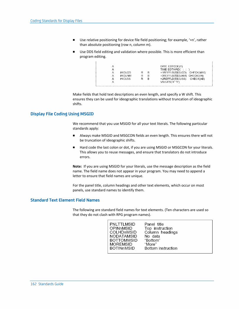
Coding Standards for Display Files
162 Standards Guide
■ Use relative positioning for device file field positioning; for example, ‘+n’, rather than absolute positioning (row n, column m).
■ Use DDS field editing and validation where possible. This is more efficient than program editing.
Make fields that hold text descriptions an even length, and specify a W shift. This ensures they can be used for ideographic translations without truncation of ideographic shifts.
Display File Coding Using MSGID
We recommend that you use MSGID for all your text literals. The following particular standards apply:
■ Always make MSGID and MSGCON fields an even length. This ensures there will not be truncation of ideographic shifts.
■ Hard code the last colon or dot, if you are using MSGID or MSGCON for your literals. This allows you to reuse messages, and ensure that translators do not introduce errors.
Note: If you are using MSGID for your literals, use the message description as the field name. The field name does not appear in your program. You may need to append a letter to ensure that field names are unique.
For the panel title, column headings and other text elements, which occur on most panels, use standard names to identify them.
Standard Text Element Field Names
The following are standard field names for text elements. (Ten characters are used so that they do not clash with RPG program names).
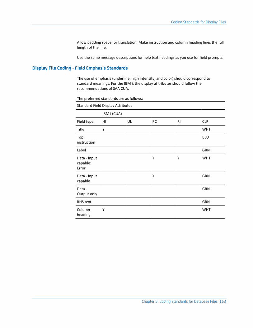
Coding Standards for Display Files
Chapter 5: Coding Standards for Database Files 163
Allow padding space for translation. Make instruction and column heading lines the full length of the line.
Use the same message descriptions for help text headings as you use for field prompts.
Display File Coding - Field Emphasis Standards
The use of emphasis (underline, high intensity, and color) should correspond to standard meanings. For the IBM i, the display at tributes should follow the recommendations of SAA CUA.
The preferred standards are as follows:
Standard Field Display Attributes
IBM i (CUA)
Field type HI UL PC RI CLR
Title Y WHT
Top instruction
BLU
Label GRN
Data - Input capable: Error
Y Y WHT
Data - Input capable
Y GRN
Data - Output only
GRN
RHS text GRN
Column heading
Y WHT
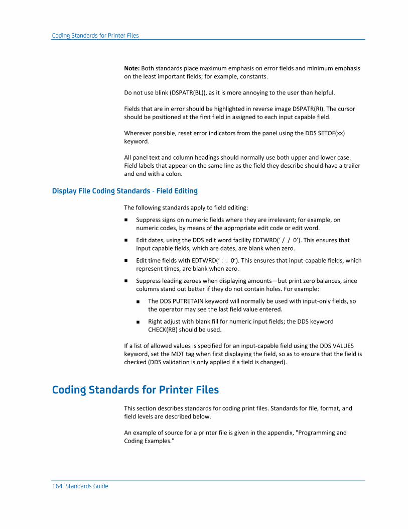
Coding Standards for Printer Files
164 Standards Guide
Note: Both standards place maximum emphasis on error fields and minimum emphasis on the least important fields; for example, constants.
Do not use blink (DSPATR(BL)), as it is more annoying to the user than helpful.
Fields that are in error should be highlighted in reverse image DSPATR(RI). The cursor should be positioned at the first field in assigned to each input capable field.
Wherever possible, reset error indicators from the panel using the DDS SETOF(xx) keyword.
All panel text and column headings should normally use both upper and lower case. Field labels that appear on the same line as the field they describe should have a trailer and end with a colon.
Display File Coding Standards - Field Editing
The following standards apply to field editing:
■ Suppress signs on numeric fields where they are irrelevant; for example, on numeric codes, by means of the appropriate edit code or edit word.
■ Edit dates, using the DDS edit word facility EDTWRD(‘ / / 0’). This ensures that input capable fields, which are dates, are blank when zero.
■ Edit time fields with EDTWRD(‘ : : 0’). This ensures that input-capable fields, which represent times, are blank when zero.
■ Suppress leading zeroes when displaying amounts—but print zero balances, since columns stand out better if they do not contain holes. For example:
■ The DDS PUTRETAIN keyword will normally be used with input-only fields, so the operator may see the last field value entered.
■ Right adjust with blank fill for numeric input fields; the DDS keyword CHECK(RB) should be used.
If a list of allowed values is specified for an input-capable field using the DDS VALUES keyword, set the MDT tag when first displaying the field, so as to ensure that the field is checked (DDS validation is only applied if a field is changed).
Coding Standards for Printer Files
This section describes standards for coding print files. Standards for file, format, and field levels are described below.
An example of source for a printer file is given in the appendix, "Programming and Coding Examples."
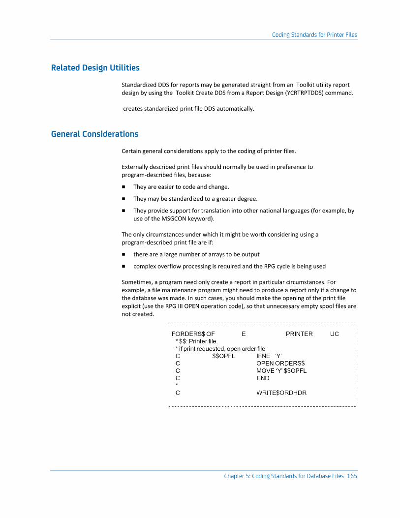
Coding Standards for Printer Files
Chapter 5: Coding Standards for Database Files 165
Related Design Utilities
Standardized DDS for reports may be generated straight from an Toolkit utility report design by using the Toolkit Create DDS from a Report Design (YCRTRPTDDS) command.
creates standardized print file DDS automatically.
General Considerations
Certain general considerations apply to the coding of printer files.
Externally described print files should normally be used in preference to program-described files, because:
■ They are easier to code and change.
■ They may be standardized to a greater degree.
■ They provide support for translation into other national languages (for example, by use of the MSGCON keyword).
The only circumstances under which it might be worth considering using a program-described print file are if:
■ there are a large number of arrays to be output
■ complex overflow processing is required and the RPG cycle is being used
Sometimes, a program need only create a report in particular circumstances. For example, a file maintenance program might need to produce a report only if a change to the database was made. In such cases, you should make the opening of the print file explicit (use the RPG III OPEN operation code), so that unnecessary empty spool files are not created.
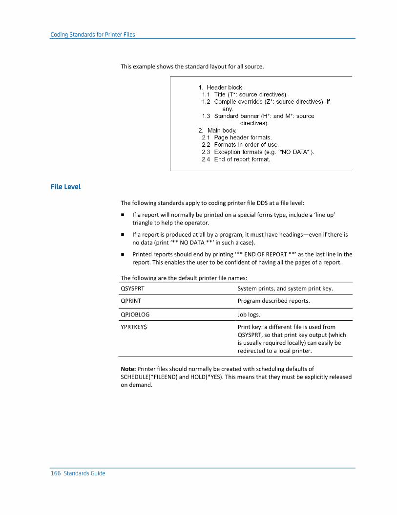
Coding Standards for Printer Files
166 Standards Guide
This example shows the standard layout for all source.
File Level
The following standards apply to coding printer file DDS at a file level:
■ If a report will normally be printed on a special forms type, include a ‘line up’ triangle to help the operator.
■ If a report is produced at all by a program, it must have headings—even if there is no data (print ‘** NO DATA **‘ in such a case).
■ Printed reports should end by printing ‘** END OF REPORT **’ as the last line in the report. This enables the user to be confident of having all the pages of a report.
The following are the default printer file names:
QSYSPRT System prints, and system print key.
QPRINT Program described reports.
QPJOBLOG Job logs.
YPRTKEY$ Print key: a different file is used from QSYSPRT, so that print key output (which is usually required locally) can easily be redirected to a local printer.
Note: Printer files should normally be created with scheduling defaults of SCHEDULE(*FILEEND) and HOLD(*YES). This means that they must be explicitly released on demand.
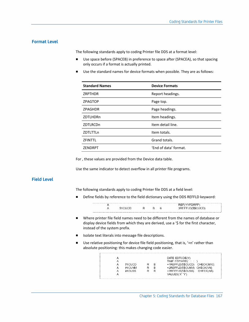
Coding Standards for Printer Files
Chapter 5: Coding Standards for Database Files 167
Format Level
The following standards apply to coding Printer file DDS at a format level:
■ Use space before (SPACEB) in preference to space after (SPACEA), so that spacing only occurs if a format is actually printed.
■ Use the standard names for device formats when possible. They are as follows:
Standard Names Device Formats
ZRPTHDR Report headings.
ZPAGTOP Page top.
ZPAGHDR Page headings.
ZDTLHDRn Item headings.
ZDTLRCDn Item detail line.
ZDTLTTLn Item totals.
ZFINTTL Grand totals.
ZENDRPT ‘End of data’ format.
For , these values are provided from the Device data table.
Use the same indicator to detect overflow in all printer file programs.
Field Level
The following standards apply to coding Printer file DDS at a field level:
■ Define fields by reference to the field dictionary using the DDS REFFLD keyword:
■ Where printer file field names need to be different from the names of database or display device fields from which they are derived, use a ‘$ for the first character, instead of the system prefix.
■ Isolate text literals into message file descriptions.
■ Use relative positioning for device file field positioning, that is, ‘+n’ rather than absolute positioning: this makes changing code easier.
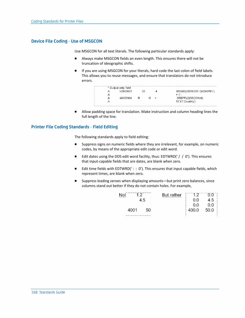
Coding Standards for Printer Files
168 Standards Guide
Device File Coding - Use of MSGCON
Use MSGCON for all text literals. The following particular standards apply:
■ Always make MSGCON fields an even length. This ensures there will not be truncation of ideographic shifts.
■ If you are using MSGCON for your literals, hard code the last colon of field labels. This allows you to reuse messages, and ensure that translators do not introduce errors.
■ Allow padding space for translation. Make instruction and column heading lines the full length of the line.
Printer File Coding Standards - Field Editing
The following standards apply to field editing:
■ Suppress signs on numeric fields where they are irrelevant, for example, on numeric codes, by means of the appropriate edit code or edit word.
■ Edit dates using the DDS edit word facility, thus: EDTWRD(‘ / / 0’). This ensures that input-capable fields that are dates, are blank when zero.
■ Edit time fields with EDTWRD(‘ : : 0’). This ensures that input capable fields, which represent times, are blank when zero.
■ Suppress leading zeroes when displaying amounts—but print zero balances, since columns stand out better if they do not contain holes. For example,
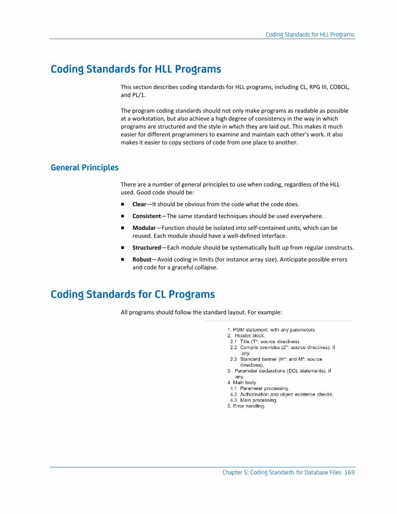
Coding Standards for HLL Programs
Chapter 5: Coding Standards for Database Files 169
Coding Standards for HLL Programs
This section describes coding standards for HLL programs, including CL, RPG III, COBOL, and PL/1.
The program coding standards should not only make programs as readable as possible at a workstation, but also achieve a high degree of consistency in the way in which programs are structured and the style in which they are laid out. This makes it much easier for different programmers to examine and maintain each other's work. It also makes it easier to copy sections of code from one place to another.
General Principles
There are a number of general principles to use when coding, regardless of the HLL used. Good code should be:
■ Clear—It should be obvious from the code what the code does.
■ Consistent—The same standard techniques should be used everywhere.
■ Modular—Function should be isolated into self-contained units, which can be reused. Each module should have a well-defined interface.
■ Structured—Each module should be systematically built up from regular constructs.
■ Robust—Avoid coding in limits (for instance array size). Anticipate possible errors and code for a graceful collapse.
Coding Standards for CL Programs
All programs should follow the standard layout. For example:
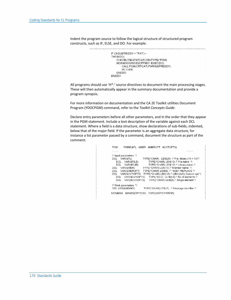
Coding Standards for CL Programs
170 Standards Guide
Indent the program source to follow the logical structure of structured program constructs, such as IF, ELSE, and DO. For example:
All programs should use ‘H*:‘ source directives to document the main processing stages. These will then automatically appear in the summary documentation and provide a program synopsis.
For more information on documentation and the CA 2E Toolkit utilities Document Program (YDOCPGM) command, refer to the Toolkit Concepts Guide.
Declare entry parameters before all other parameters, and in the order that they appear in the PGM statement. Include a text description of the variable against each DCL statement. Where a field is a data structure, show declarations of sub-fields, indented, below that of the major field. If the parameter is an aggregate data structure, for instance a list parameter passed by a command, document the structure as part of the comment:
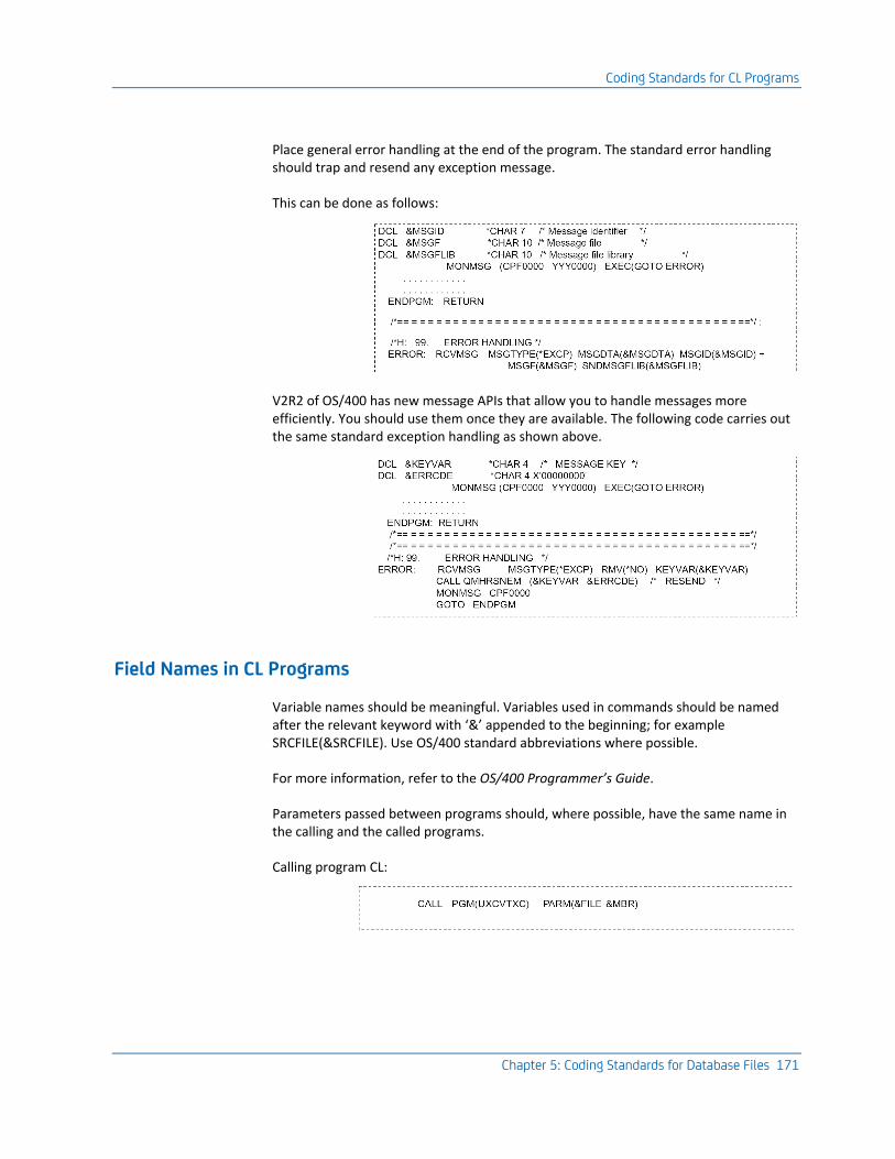
Coding Standards for CL Programs
Chapter 5: Coding Standards for Database Files 171
Place general error handling at the end of the program. The standard error handling should trap and resend any exception message.
This can be done as follows:
V2R2 of OS/400 has new message APIs that allow you to handle messages more efficiently. You should use them once they are available. The following code carries out the same standard exception handling as shown above.
Field Names in CL Programs
Variable names should be meaningful. Variables used in commands should be named after the relevant keyword with ‘&’ appended to the beginning; for example SRCFILE(&SRCFILE). Use OS/400 standard abbreviations where possible.
For more information, refer to the OS/400 Programmer’s Guide.
Parameters passed between programs should, where possible, have the same name in the calling and the called programs.
Calling program CL:
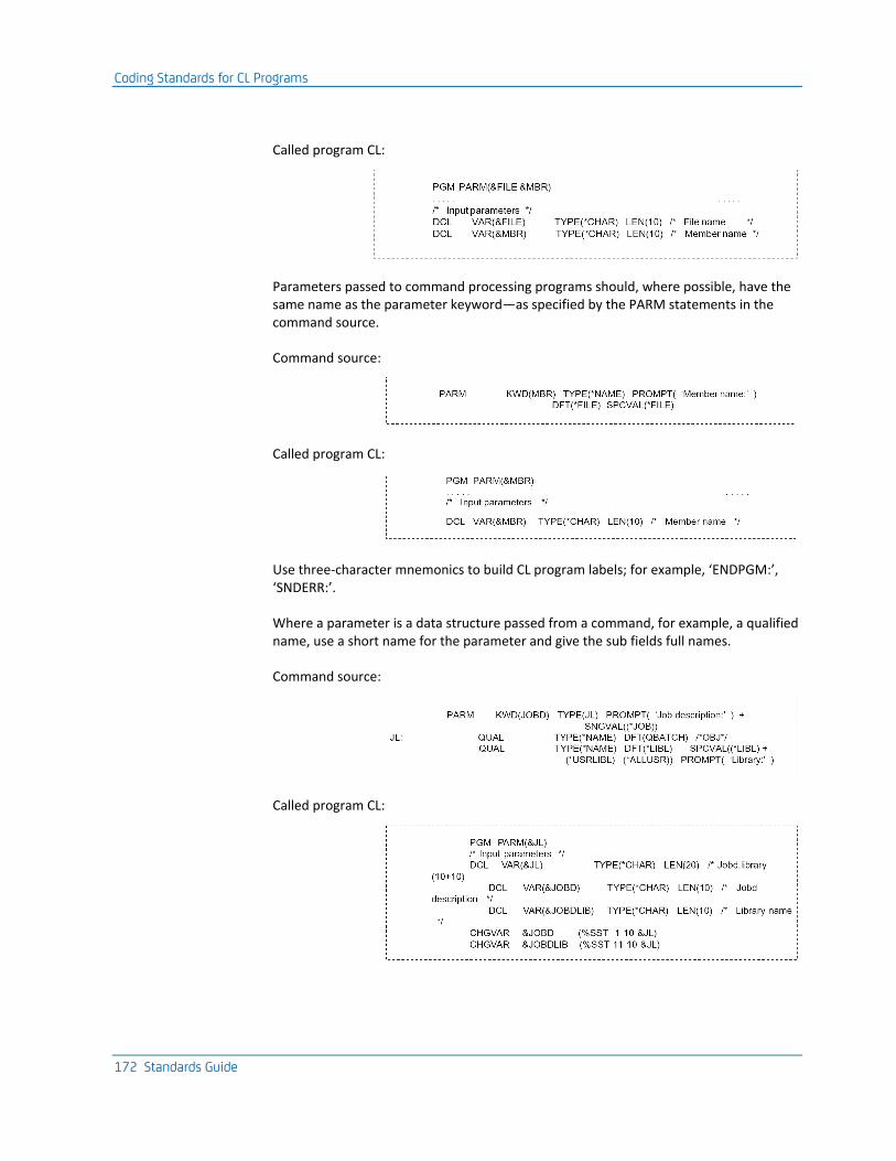
Coding Standards for CL Programs
172 Standards Guide
Called program CL:
Parameters passed to command processing programs should, where possible, have the same name as the parameter keyword—as specified by the PARM statements in the command source.
Command source:
Called program CL:
Use three-character mnemonics to build CL program labels; for example, ‘ENDPGM:’, ‘SNDERR:’.
Where a parameter is a data structure passed from a command, for example, a qualified name, use a short name for the parameter and give the sub fields full names.
Command source:
Called program CL:
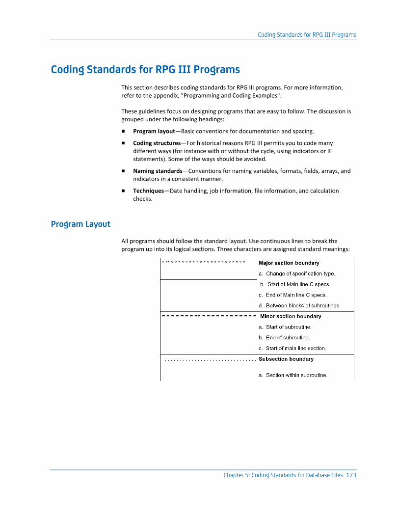
Coding Standards for RPG III Programs
Chapter 5: Coding Standards for Database Files 173
Coding Standards for RPG III Programs
This section describes coding standards for RPG III programs. For more information, refer to the appendix, "Programming and Coding Examples".
These guidelines focus on designing programs that are easy to follow. The discussion is grouped under the following headings:
■ Program layout—Basic conventions for documentation and spacing.
■ Coding structures—For historical reasons RPG III permits you to code many different ways (for instance with or without the cycle, using indicators or IF statements). Some of the ways should be avoided.
■ Naming standards—Conventions for naming variables, formats, fields, arrays, and indicators in a consistent manner.
■ Techniques—Date handling, job information, file information, and calculation checks.
Program Layout
All programs should follow the standard layout. Use continuous lines to break the program up into its logical sections. Three characters are assigned standard meanings:
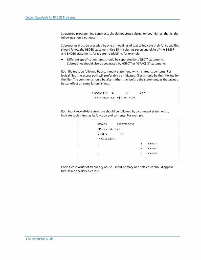
Coding Standards for RPG III Programs
174 Standards Guide
Structured programming constructs should not cross subsection boundaries; that is, the following should not occur:
Subroutines must be preceded by one or two lines of text to indicate their function. This should follow the BEGSR statement. Use SR in columns seven and eight of the BEGSR and ENDSR statements for greater readability, for example:
■ Different specification types should be separated by ‘/EJECT’ statements. Subroutines should also be separated by /EJECT‘ or ‘/SPACE 3’ statements.
Each file must be followed by a comment statement, which states its contents. For logical files, the access path will preferably be indicated. (Text should be the title line for the file). The comment should be after rather than before the statement, as that gives a better effect on compilation listings:
Each input record/data structure should be followed by a comment statement to indicate such things as its function and contents. For example:
Code files in order of frequency of use—input primary or display files should appear first. Place ancillary files last.
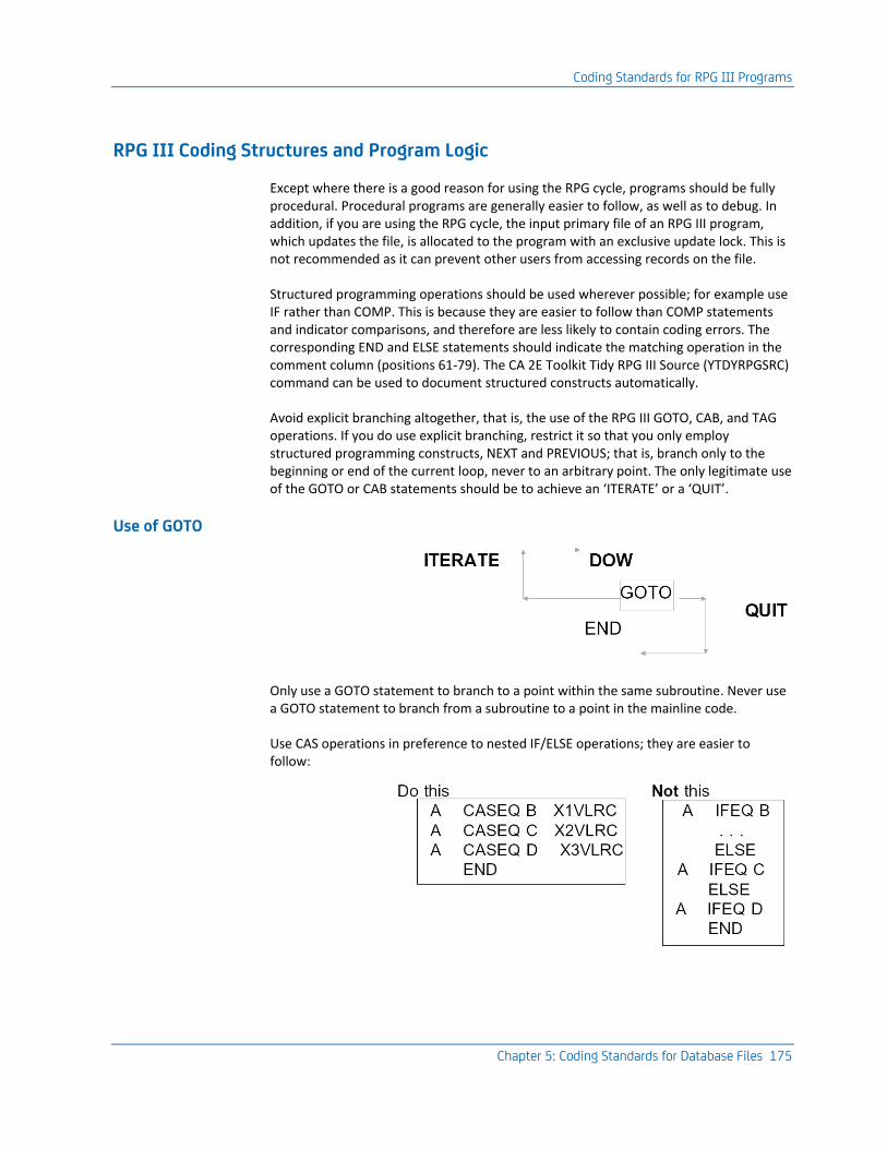
Coding Standards for RPG III Programs
Chapter 5: Coding Standards for Database Files 175
RPG III Coding Structures and Program Logic
Except where there is a good reason for using the RPG cycle, programs should be fully procedural. Procedural programs are generally easier to follow, as well as to debug. In addition, if you are using the RPG cycle, the input primary file of an RPG III program, which updates the file, is allocated to the program with an exclusive update lock. This is not recommended as it can prevent other users from accessing records on the file.
Structured programming operations should be used wherever possible; for example use IF rather than COMP. This is because they are easier to follow than COMP statements and indicator comparisons, and therefore are less likely to contain coding errors. The corresponding END and ELSE statements should indicate the matching operation in the comment column (positions 61-79). The CA 2E Toolkit Tidy RPG III Source (YTDYRPGSRC) command can be used to document structured constructs automatically.
Avoid explicit branching altogether, that is, the use of the RPG III GOTO, CAB, and TAG operations. If you do use explicit branching, restrict it so that you only employ structured programming constructs, NEXT and PREVIOUS; that is, branch only to the beginning or end of the current loop, never to an arbitrary point. The only legitimate use of the GOTO or CAB statements should be to achieve an ‘ITERATE’ or a ‘QUIT’.
Use of GOTO
Only use a GOTO statement to branch to a point within the same subroutine. Never use a GOTO statement to branch from a subroutine to a point in the mainline code.
Use CAS operations in preference to nested IF/ELSE operations; they are easier to follow:
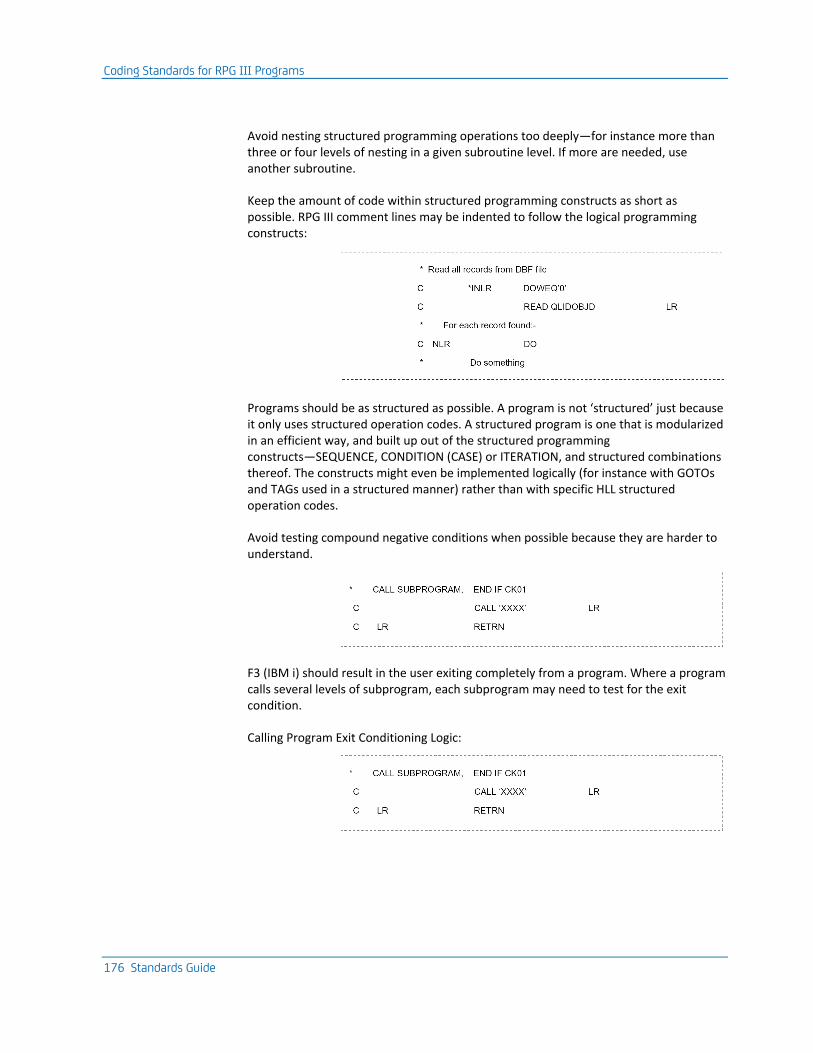
Coding Standards for RPG III Programs
176 Standards Guide
Avoid nesting structured programming operations too deeply—for instance more than three or four levels of nesting in a given subroutine level. If more are needed, use another subroutine.
Keep the amount of code within structured programming constructs as short as possible. RPG III comment lines may be indented to follow the logical programming constructs:
Programs should be as structured as possible. A program is not ‘structured’ just because it only uses structured operation codes. A structured program is one that is modularized in an efficient way, and built up out of the structured programming constructs—SEQUENCE, CONDITION (CASE) or ITERATION, and structured combinations thereof. The constructs might even be implemented logically (for instance with GOTOs and TAGs used in a structured manner) rather than with specific HLL structured operation codes.
Avoid testing compound negative conditions when possible because they are harder to understand.
F3 (IBM i) should result in the user exiting completely from a program. Where a program calls several levels of subprogram, each subprogram may need to test for the exit condition.
Calling Program Exit Conditioning Logic:
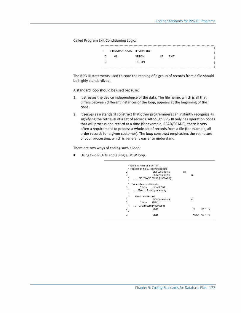
Coding Standards for RPG III Programs
Chapter 5: Coding Standards for Database Files 177
Called Program Exit Conditioning Logic:
The RPG III statements used to code the reading of a group of records from a file should be highly standardized.
A standard loop should be used because:
1. It stresses the device independence of the data. The file name, which is all that differs between different instances of the loop, appears at the beginning of the code.
2. It serves as a standard construct that other programmers can instantly recognize as signifying the retrieval of a set of records. Although RPG III only has operation codes that will process one record at a time (for example, READ/READE), there is very often a requirement to process a whole set of records from a file (for example, all order records for a given customer). The loop construct emphasizes the set nature of your processing, which is generally easier to understand.
There are two ways of coding such a loop:
■ Using two READs and a single DOW loop.
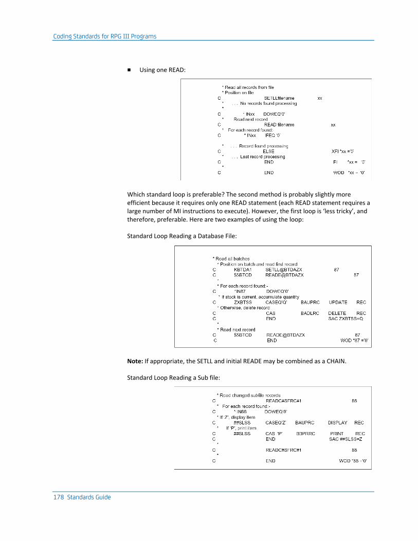
Coding Standards for RPG III Programs
178 Standards Guide
■ Using one READ:
Which standard loop is preferable? The second method is probably slightly more efficient because it requires only one READ statement (each READ statement requires a large number of MI instructions to execute). However, the first loop is ‘less tricky’, and therefore, preferable. Here are two examples of using the loop:
Standard Loop Reading a Database File:
Note: If appropriate, the SETLL and initial READE may be combined as a CHAIN.
Standard Loop Reading a Sub file:
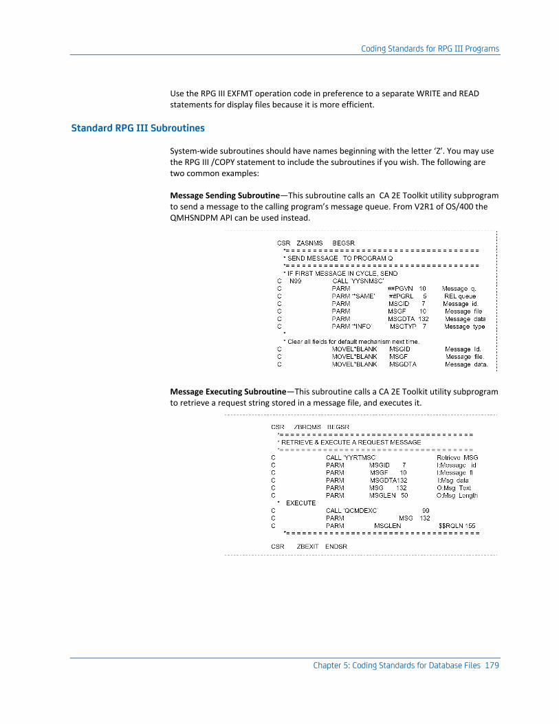
Coding Standards for RPG III Programs
Chapter 5: Coding Standards for Database Files 179
Use the RPG III EXFMT operation code in preference to a separate WRITE and READ statements for display files because it is more efficient.
Standard RPG III Subroutines
System-wide subroutines should have names beginning with the letter ‘Z’. You may use the RPG III /COPY statement to include the subroutines if you wish. The following are two common examples:
Message Sending Subroutine—This subroutine calls an CA 2E Toolkit utility subprogram to send a message to the calling program’s message queue. From V2R1 of OS/400 the QMHSNDPM API can be used instead.
Message Executing Subroutine—This subroutine calls a CA 2E Toolkit utility subprogram to retrieve a request string stored in a message file, and executes it.
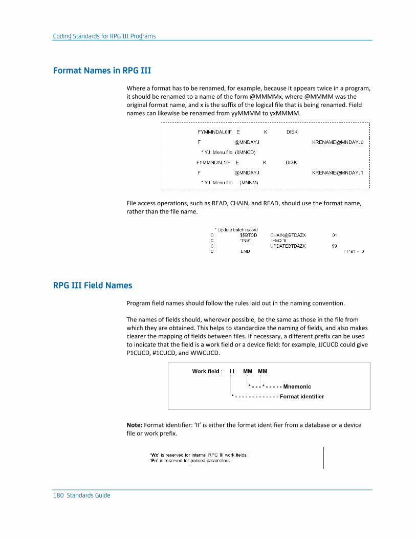
Coding Standards for RPG III Programs
180 Standards Guide
Format Names in RPG III
Where a format has to be renamed, for example, because it appears twice in a program, it should be renamed to a name of the form @MMMMx, where @MMMM was the original format name, and x is the suffix of the logical file that is being renamed. Field names can likewise be renamed from yyMMMM to yxMMMM.
File access operations, such as READ, CHAIN, and READ, should use the format name, rather than the file name.
RPG III Field Names
Program field names should follow the rules laid out in the naming convention.
The names of fields should, wherever possible, be the same as those in the file from which they are obtained. This helps to standardize the naming of fields, and also makes clearer the mapping of fields between files. If necessary, a different prefix can be used to indicate that the field is a work field or a device field: for example, JJCUCD could give P1CUCD, #1CUCD, and WWCUCD.
Note: Format identifier: ‘II’ is either the format identifier from a database or a device file or work prefix.
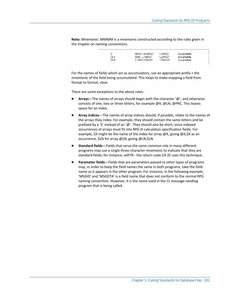
Coding Standards for RPG III Programs
Chapter 5: Coding Standards for Database Files 181
Note: Mnemonic: MMMM is a mnemonic constructed according to the rules given in the chapter on naming conventions.
For the names of fields which act as accumulators, use an appropriate prefix + the mnemonic of the field being accumulated. This helps to make mapping a field from format to format, clear.
There are some exceptions to the above rules:
■ Arrays—The names of arrays should begin with the character ‘@’, and otherwise consists of one, two or three letters, for example @X, @LN, @PRC. This leaves space for an index.
■ Array indices—The names of array indices should, if possible, relate to the names of the arrays they index. For example, they should contain the same letters and be prefixed by a ‘$’ instead of an ‘@’. They should also be short, since indexed occurrences of arrays must fit into RPG III calculation specification fields. For example, $X might be the name of the index for array @X, giving @X,$X as an occurrence, $LN for array @LN, giving @LN,$LN.
■ Standard fields—Fields that serve the same common role in many different programs may use a single three-character mnemonic to indicate that they are standard fields; for instance, xxRTN - the return code.CA 2E uses this technique.
■ Parameter fields—Fields that are parameters passed to other types of programs may, in order to keep the field names the same in both programs, take the field name as it appears in the other program. For instance, in the following example, ‘MSGID’ and ‘MSGDTA’ is a field name that does not conform to the normal RPG naming convention. However, it is the name used in the CL message-sending program that is being called.
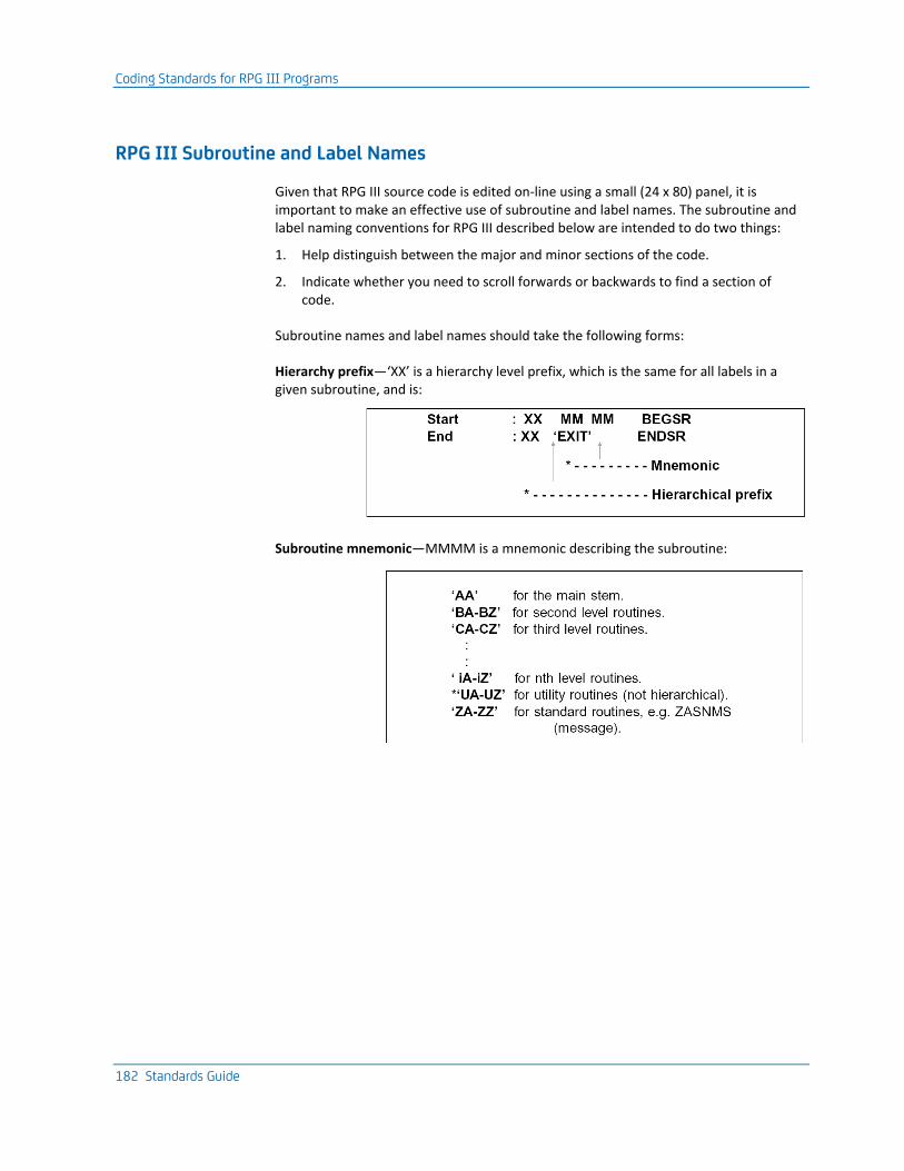
Coding Standards for RPG III Programs
182 Standards Guide
RPG III Subroutine and Label Names
Given that RPG III source code is edited on-line using a small (24 x 80) panel, it is important to make an effective use of subroutine and label names. The subroutine and label naming conventions for RPG III described below are intended to do two things:
1. Help distinguish between the major and minor sections of the code.
2. Indicate whether you need to scroll forwards or backwards to find a section of code.
Subroutine names and label names should take the following forms:
Hierarchy prefix—‘XX’ is a hierarchy level prefix, which is the same for all labels in a given subroutine, and is:
Subroutine mnemonic—MMMM is a mnemonic describing the subroutine:
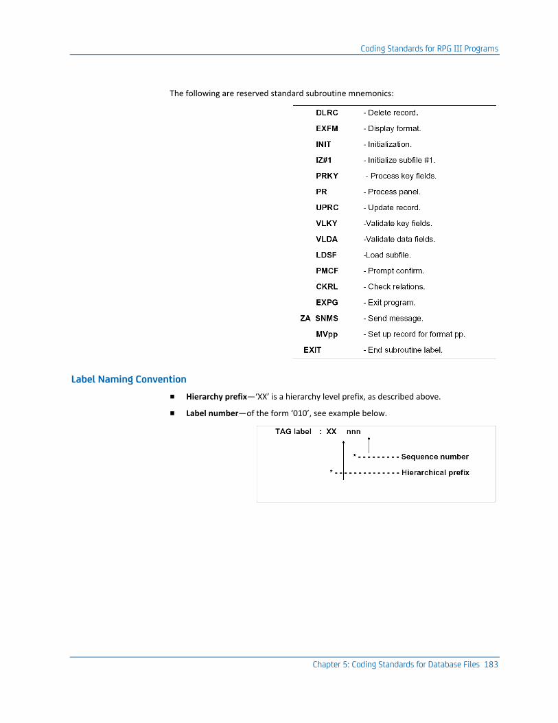
Coding Standards for RPG III Programs
Chapter 5: Coding Standards for Database Files 183
The following are reserved standard subroutine mnemonics:
Label Naming Convention
■ Hierarchy prefix—‘XX’ is a hierarchy level prefix, as described above.
■ Label number—of the form ‘010’, see example below.
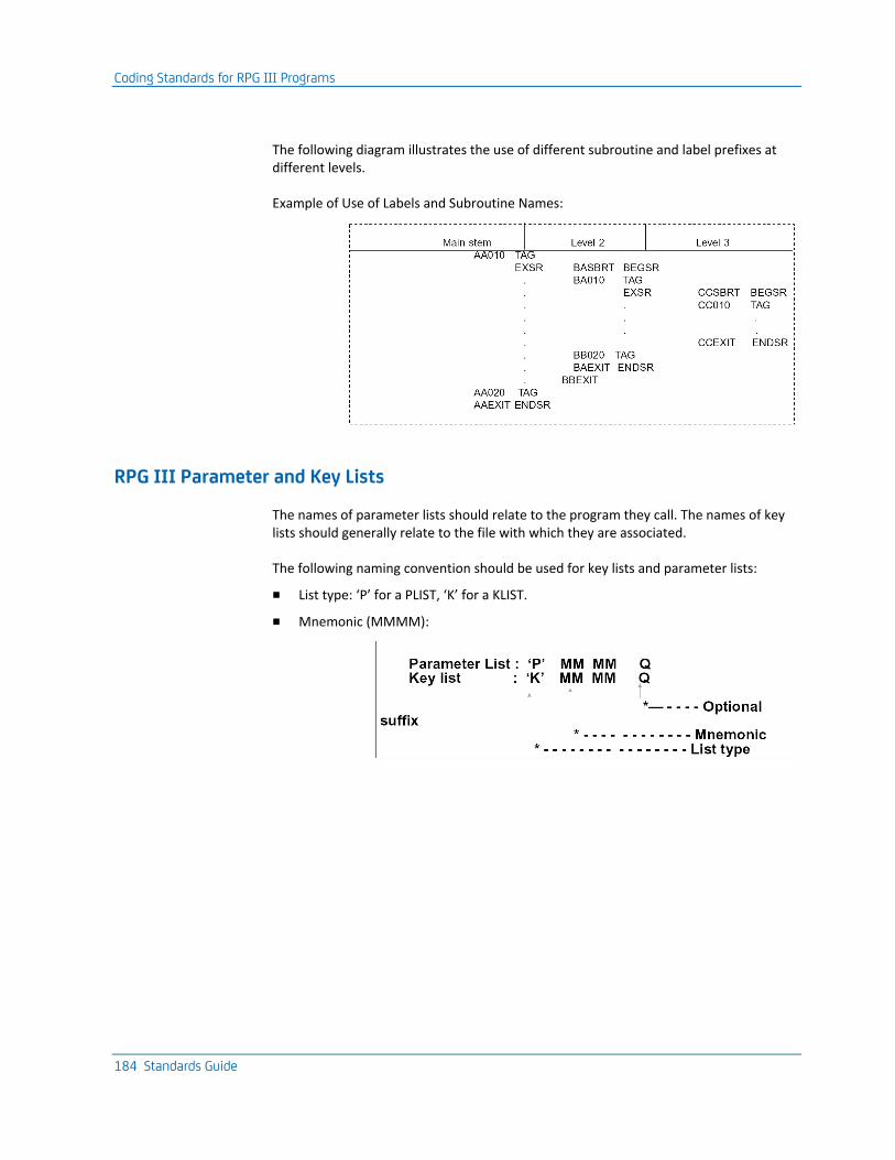
Coding Standards for RPG III Programs
184 Standards Guide
The following diagram illustrates the use of different subroutine and label prefixes at different levels.
Example of Use of Labels and Subroutine Names:
RPG III Parameter and Key Lists
The names of parameter lists should relate to the program they call. The names of key lists should generally relate to the file with which they are associated.
The following naming convention should be used for key lists and parameter lists:
■ List type: ‘P’ for a PLIST, ‘K’ for a KLIST.
■ Mnemonic (MMMM):
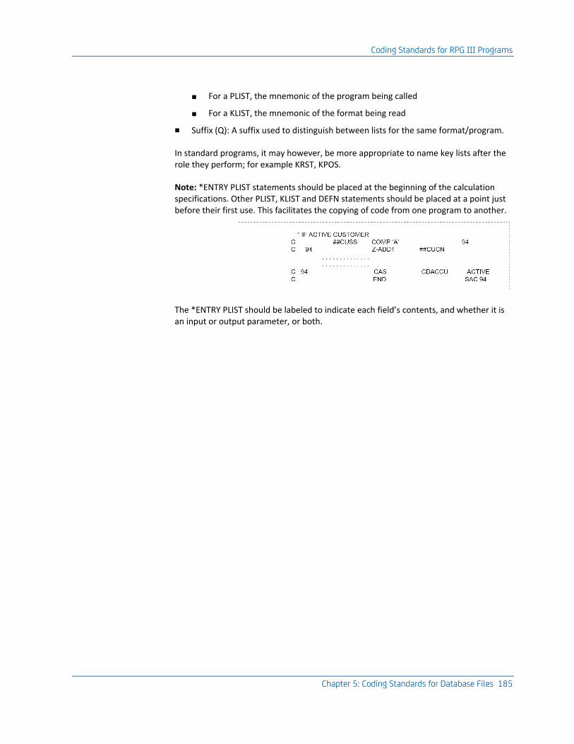
Coding Standards for RPG III Programs
Chapter 5: Coding Standards for Database Files 185
■ For a PLIST, the mnemonic of the program being called
■ For a KLIST, the mnemonic of the format being read
■ Suffix (Q): A suffix used to distinguish between lists for the same format/program.
In standard programs, it may however, be more appropriate to name key lists after the role they perform; for example KRST, KPOS.
Note: *ENTRY PLIST statements should be placed at the beginning of the calculation specifications. Other PLIST, KLIST and DEFN statements should be placed at a point just before their first use. This facilitates the copying of code from one program to another.
The *ENTRY PLIST should be labeled to indicate each field’s contents, and whether it is an input or output parameter, or both.
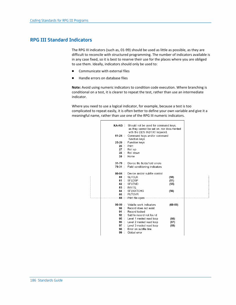
Coding Standards for RPG III Programs
186 Standards Guide
RPG III Standard Indicators
The RPG III indicators (such as, 01-99) should be used as little as possible, as they are difficult to reconcile with structured programming. The number of indicators available is in any case fixed, so it is best to reserve their use for the places where you are obliged to use them. Ideally, indicators should only be used to:
■ Communicate with external files
■ Handle errors on database files
Note: Avoid using numeric indicators to condition code execution. Where branching is conditional on a test, it is clearer to repeat the test, rather than use an intermediate indicator.
Where you need to use a logical indicator, for example, because a test is too complicated to repeat easily, it is often better to define your own variable and give it a meaningful name, rather than use one of the RPG III numeric indicators.
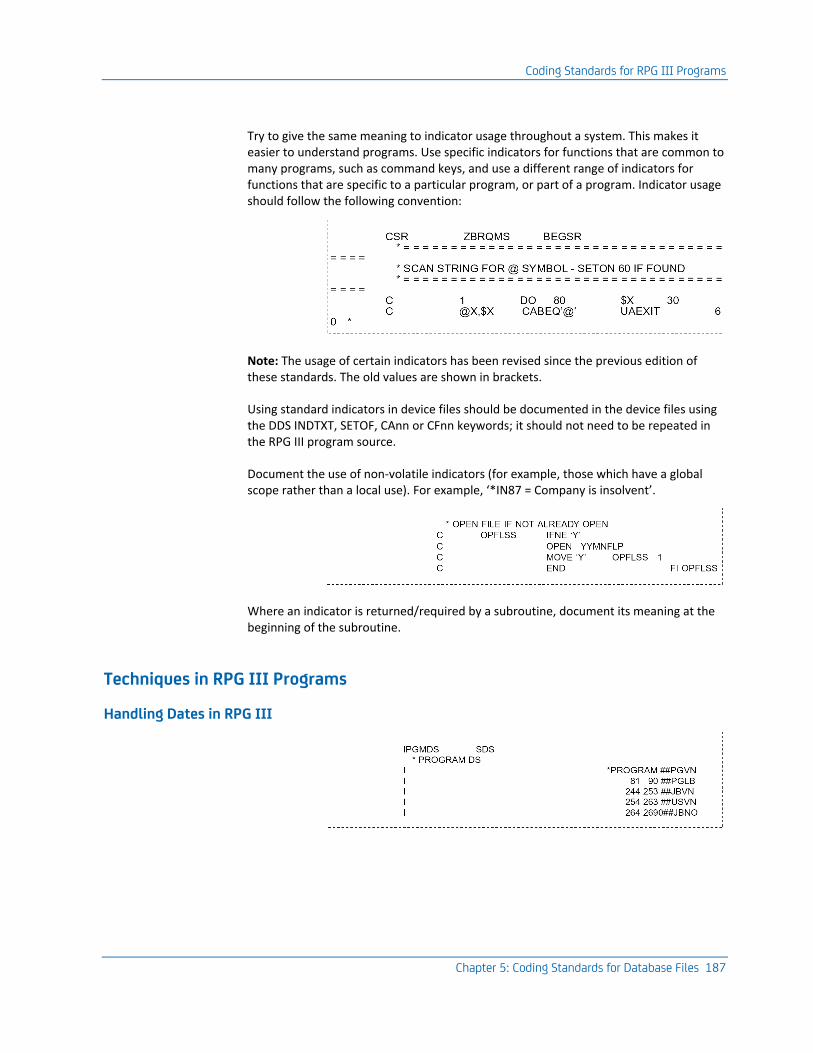
Coding Standards for RPG III Programs
Chapter 5: Coding Standards for Database Files 187
Try to give the same meaning to indicator usage throughout a system. This makes it easier to understand programs. Use specific indicators for functions that are common to many programs, such as command keys, and use a different range of indicators for functions that are specific to a particular program, or part of a program. Indicator usage should follow the following convention:
Note: The usage of certain indicators has been revised since the previous edition of these standards. The old values are shown in brackets.
Using standard indicators in device files should be documented in the device files using the DDS INDTXT, SETOF, CAnn or CFnn keywords; it should not need to be repeated in the RPG III program source.
Document the use of non-volatile indicators (for example, those which have a global scope rather than a local use). For example, ‘*IN87 = Company is insolvent’.
Where an indicator is returned/required by a subroutine, document its meaning at the beginning of the subroutine.
Techniques in RPG III Programs
Handling Dates in RPG III
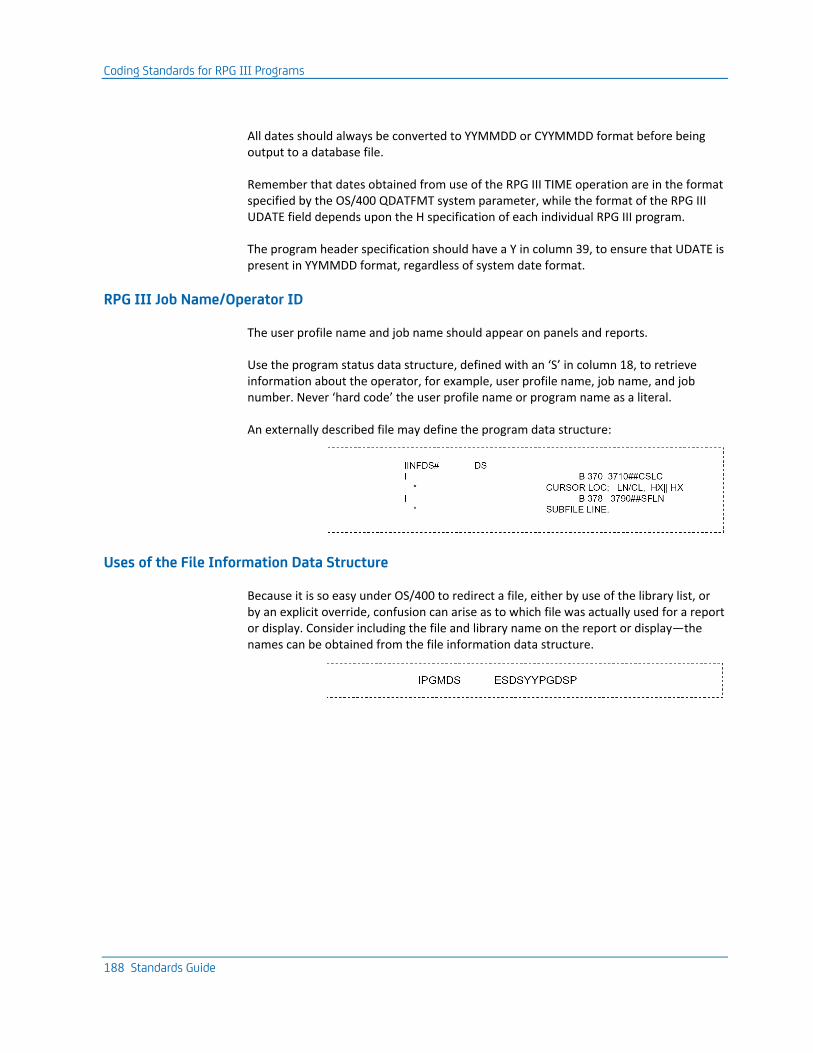
Coding Standards for RPG III Programs
188 Standards Guide
All dates should always be converted to YYMMDD or CYYMMDD format before being output to a database file.
Remember that dates obtained from use of the RPG III TIME operation are in the format specified by the OS/400 QDATFMT system parameter, while the format of the RPG III UDATE field depends upon the H specification of each individual RPG III program.
The program header specification should have a Y in column 39, to ensure that UDATE is present in YYMMDD format, regardless of system date format.
RPG III Job Name/Operator ID
The user profile name and job name should appear on panels and reports.
Use the program status data structure, defined with an ‘S’ in column 18, to retrieve information about the operator, for example, user profile name, job name, and job number. Never ‘hard code’ the user profile name or program name as a literal.
An externally described file may define the program data structure:
Uses of the File Information Data Structure
Because it is so easy under OS/400 to redirect a file, either by use of the library list, or by an explicit override, confusion can arise as to which file was actually used for a report or display. Consider including the file and library name on the report or display—the names can be obtained from the file information data structure.
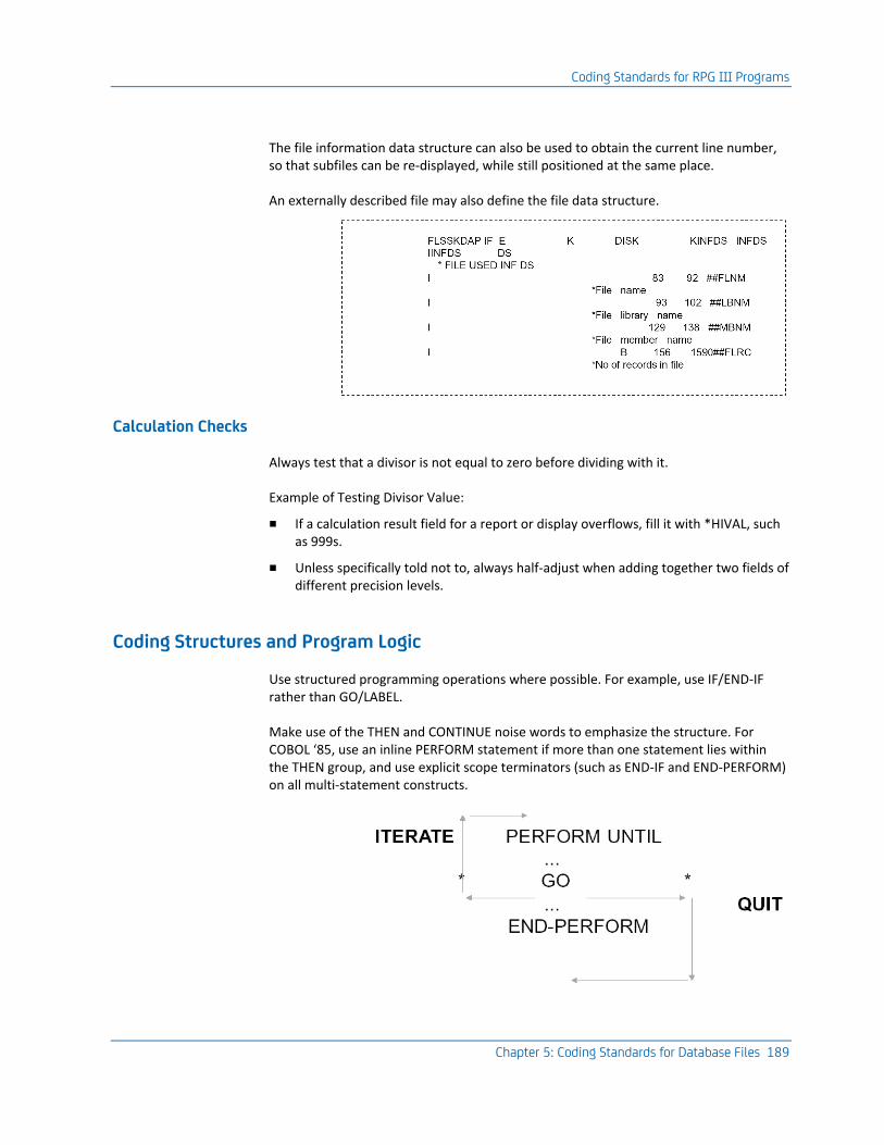
Coding Standards for RPG III Programs
Chapter 5: Coding Standards for Database Files 189
The file information data structure can also be used to obtain the current line number, so that subfiles can be re-displayed, while still positioned at the same place.
An externally described file may also define the file data structure.
Calculation Checks
Always test that a divisor is not equal to zero before dividing with it.
Example of Testing Divisor Value:
■ If a calculation result field for a report or display overflows, fill it with *HIVAL, such as 999s.
■ Unless specifically told not to, always half-adjust when adding together two fields of different precision levels.
Coding Structures and Program Logic
Use structured programming operations where possible. For example, use IF/END-IF rather than GO/LABEL.
Make use of the THEN and CONTINUE noise words to emphasize the structure. For COBOL ‘85, use an inline PERFORM statement if more than one statement lies within the THEN group, and use explicit scope terminators (such as END-IF and END-PERFORM) on all multi-statement constructs.
Coding Standards for COBOL Programs
190 Standards Guide
Avoid explicit branching (the use of the COBOL GO operation) as much as possible. Where you do use explicit branching, try to do so in a structured way, and to build up structured programming constructs, NEXT and PREVIOUS. In other words, branch only to the beginning or end of the current loop, never to an arbitrary point. The only legitimate use of the GO statements should be to achieve an ‘ITERATE’ or a ‘QUIT’.
Coding Standards for COBOL Programs
The majority of the guidelines given in this section are concerned with making the COBOL code easy to follow and understand, and the intent clear. The section is grouped under the following headings:
■ Program layout—Basic conventions for documentation and spacing.
■ Coding techniques—Preferred methods for using structured coding techniques.
■ Naming standards—Conventions for naming variables (formats, fields, arrays, indicators) in a consistent manner.
■ Techniques—Date handling, job name/operator ID, calculation checks.
All examples presented use COBOL ‘85 syntax, unless otherwise stated.
Note: For more information on the standards for COBOL programs, refer to the appendix, "Programming and Coding Examples."
Language Standards
Do not use COBOL language features identified as obsolete in the ANSI standard, as these elements will be deleted in the next edition of the standard.
On the IBM i, use COBOL ‘85 in preference to COBOL ‘74.
Numeric variables should be declared as signed, odd-length, COMPUTATIONAL (packed decimal). This gives a more efficient implementation.
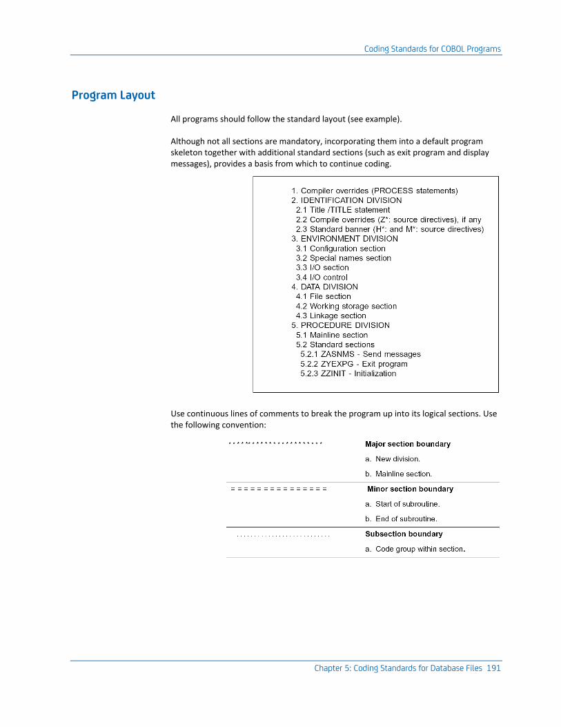
Coding Standards for COBOL Programs
Chapter 5: Coding Standards for Database Files 191
Program Layout
All programs should follow the standard layout (see example).
Although not all sections are mandatory, incorporating them into a default program skeleton together with additional standard sections (such as exit program and display messages), provides a basis from which to continue coding.
Use continuous lines of comments to break the program up into its logical sections. Use the following convention:
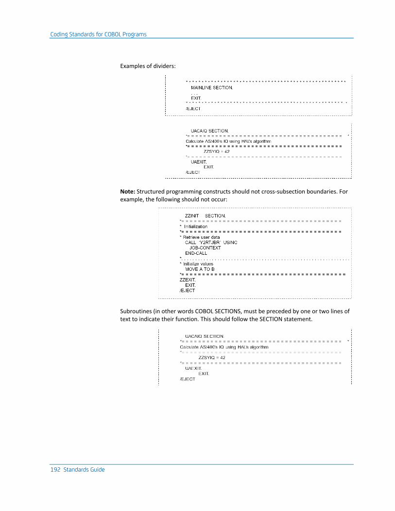
Coding Standards for COBOL Programs
192 Standards Guide
Examples of dividers:
Note: Structured programming constructs should not cross-subsection boundaries. For example, the following should not occur:
Subroutines (in other words COBOL SECTIONS, must be preceded by one or two lines of text to indicate their function. This should follow the SECTION statement.

Coding Standards for COBOL Programs
Chapter 5: Coding Standards for Database Files 193
Code should be indented to indicate the structure. For example:
Note: Different sections should be separated by the ‘/ ‘ compiler directive in the continuation area, which directs the printer to advance to a new page. To identify this line further, a standard comment should follow this, for example ‘EJECT’.
Place each phrase of a file declaration on a new line. A comment statement, giving its full text name, must follow each file declaration statement:
Place each phrase of a program call statement on a new line:
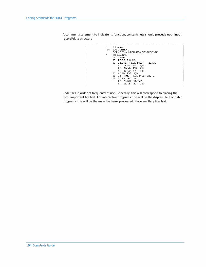
Coding Standards for COBOL Programs
194 Standards Guide
A comment statement to indicate its function, contents, etc should precede each input record/data structure:
Code files in order of frequency of use. Generally, this will correspond to placing the most important file first. For interactive programs, this will be the display file. For batch programs, this will be the main file being processed. Place ancillary files last.
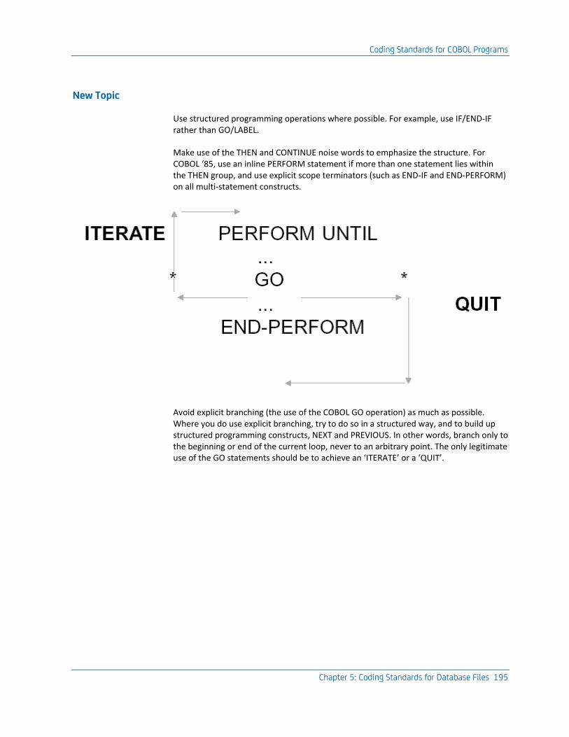
Coding Standards for COBOL Programs
Chapter 5: Coding Standards for Database Files 195
New Topic
Use structured programming operations where possible. For example, use IF/END-IF rather than GO/LABEL.
Make use of the THEN and CONTINUE noise words to emphasize the structure. For COBOL ‘85, use an inline PERFORM statement if more than one statement lies within the THEN group, and use explicit scope terminators (such as END-IF and END-PERFORM) on all multi-statement constructs.
Avoid explicit branching (the use of the COBOL GO operation) as much as possible. Where you do use explicit branching, try to do so in a structured way, and to build up structured programming constructs, NEXT and PREVIOUS. In other words, branch only to the beginning or end of the current loop, never to an arbitrary point. The only legitimate use of the GO statements should be to achieve an ‘ITERATE’ or a ‘QUIT’.

Coding Standards for COBOL Programs
196 Standards Guide
Use of GO
Only use a GO statement to branch to a point within the same subroutine. Never use a GO statement to branch from a subroutine to a point in the mainline code. Although this can be accomplished using COBOL, it should be regarded as being contrary to the basic tenets of structured programming.
Avoid nesting structured programming operations too deeply. For example, more than three or four levels of nesting in a given section level. If more are needed, use another section.
Programs should be as structured as possible. A program is not ‘structured’ just because it only uses structured operation codes. A structured program is one that is modularized in an efficient way and built up out of the structured programming constructs—SEQUENCE, CONDITION (CASE) or ITERATION, and structured combinations thereof. The constructs might even be implemented logically (for instance, with GO statements used in a structured manner) rather than with specific HLL structured operation codes.
The COBOL statements used to code the reading of a group of records from a file should be highly standardized.
A standard loop should be used because:
■ It stresses the ‘device independence’ of the data. The file name, which is all that differs between different instances of the loop, appears at the beginning of the code.
■ It serves as a standard construct that other programmers can instantly recognize as signifying the retrieval of a set of records. Although COBOL only has operation codes that will process one record at a time (such as READ), there is very often a requirement to process a whole set of records from a file (for example, all order records for a given customer). The loop construct emphasizes the ‘set’ nature of your processing, which is generally easier to understand.
READ loop - COBOL ‘85:
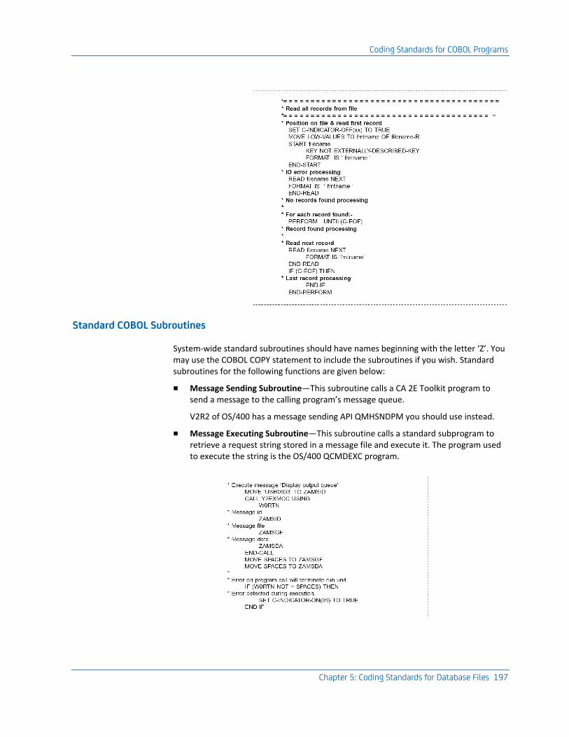
Coding Standards for COBOL Programs
Chapter 5: Coding Standards for Database Files 197
Standard COBOL Subroutines
System-wide standard subroutines should have names beginning with the letter ‘Z’. You may use the COBOL COPY statement to include the subroutines if you wish. Standard subroutines for the following functions are given below:
■ Message Sending Subroutine—This subroutine calls a CA 2E Toolkit program to send a message to the calling program’s message queue.
V2R2 of OS/400 has a message sending API QMHSNDPM you should use instead.
■ Message Executing Subroutine—This subroutine calls a standard subprogram to retrieve a request string stored in a message file and execute it. The program used to execute the string is the OS/400 QCMDEXC program.
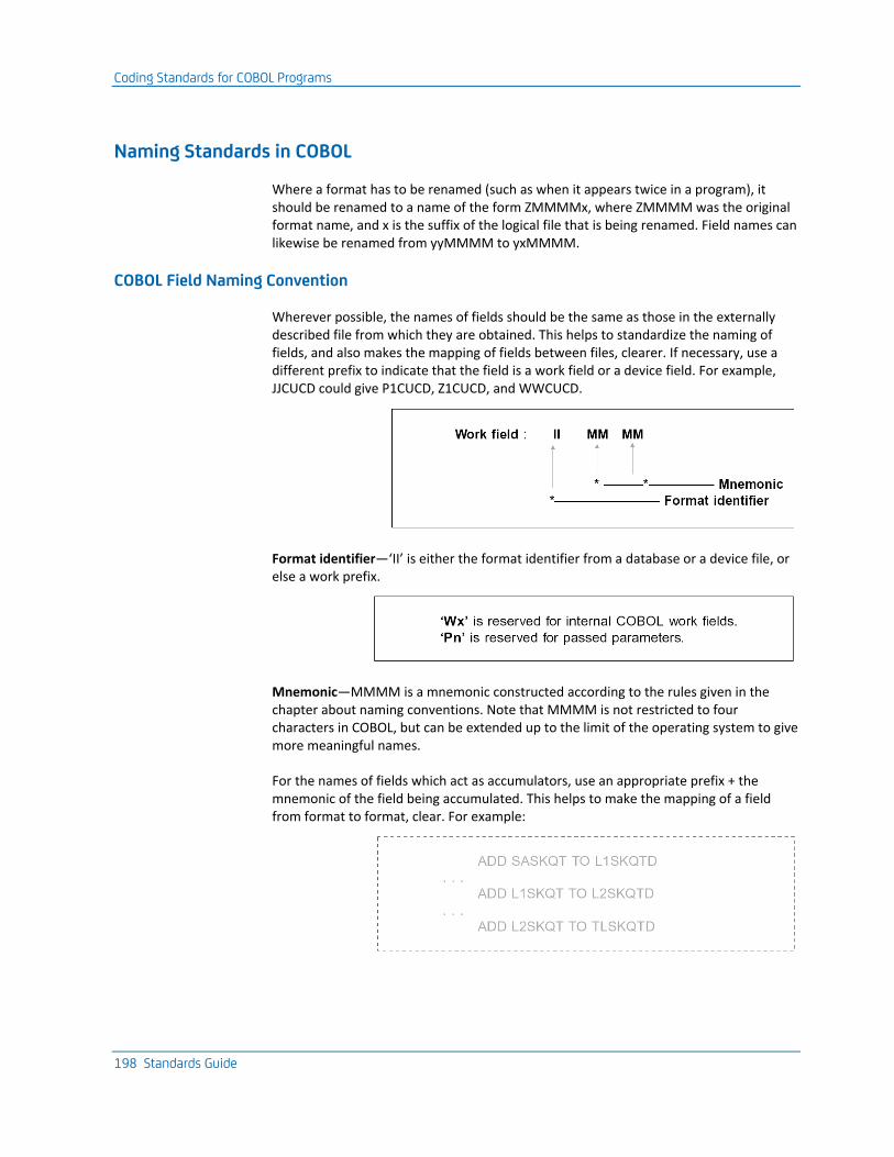
Coding Standards for COBOL Programs
198 Standards Guide
Naming Standards in COBOL
Where a format has to be renamed (such as when it appears twice in a program), it should be renamed to a name of the form ZMMMMx, where ZMMMM was the original format name, and x is the suffix of the logical file that is being renamed. Field names can likewise be renamed from yyMMMM to yxMMMM.
COBOL Field Naming Convention
Wherever possible, the names of fields should be the same as those in the externally described file from which they are obtained. This helps to standardize the naming of fields, and also makes the mapping of fields between files, clearer. If necessary, use a different prefix to indicate that the field is a work field or a device field. For example, JJCUCD could give P1CUCD, Z1CUCD, and WWCUCD.
Format identifier—‘II’ is either the format identifier from a database or a device file, or else a work prefix.
Mnemonic—MMMM is a mnemonic constructed according to the rules given in the chapter about naming conventions. Note that MMMM is not restricted to four characters in COBOL, but can be extended up to the limit of the operating system to give more meaningful names.
For the names of fields which act as accumulators, use an appropriate prefix + the mnemonic of the field being accumulated. This helps to make the mapping of a field from format to format, clear. For example:
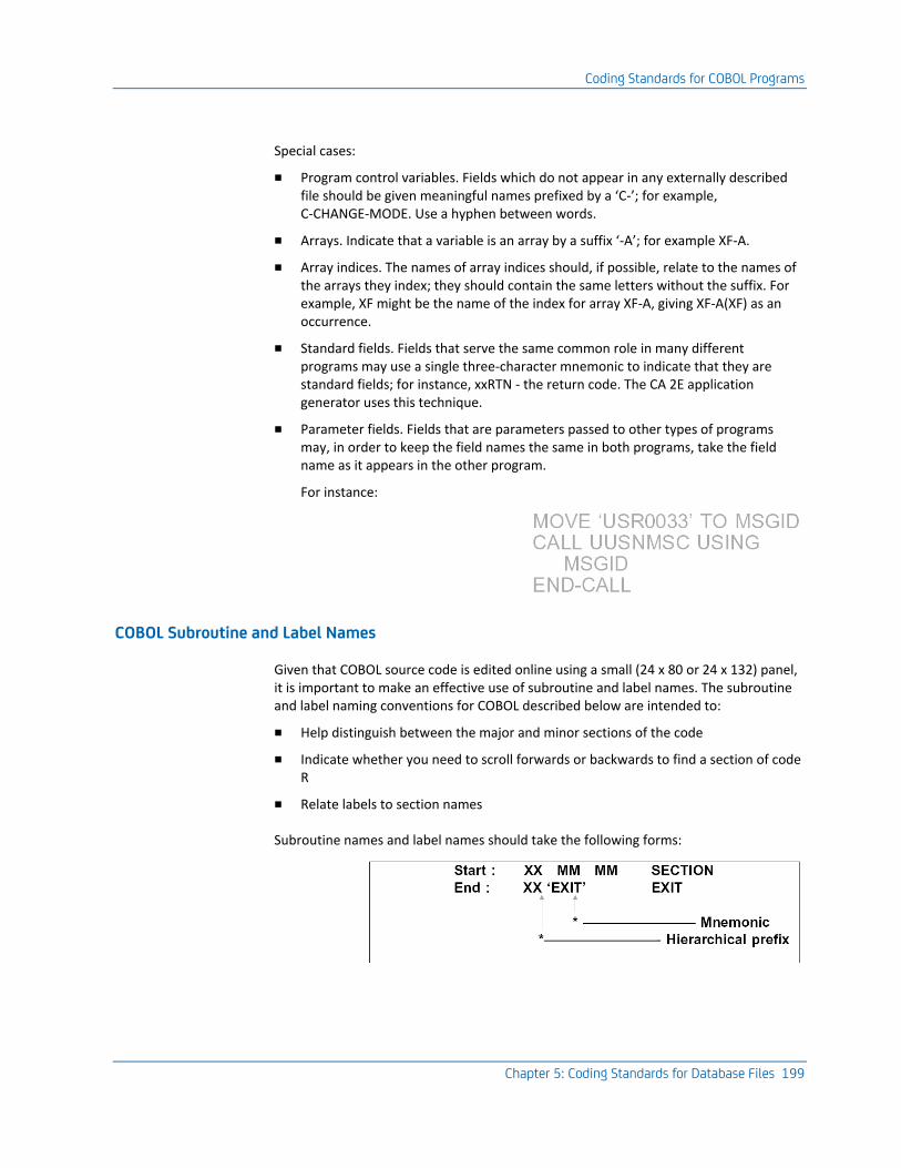
Coding Standards for COBOL Programs
Chapter 5: Coding Standards for Database Files 199
Special cases:
■ Program control variables. Fields which do not appear in any externally described file should be given meaningful names prefixed by a ‘C-’; for example, C-CHANGE-MODE. Use a hyphen between words.
■ Arrays. Indicate that a variable is an array by a suffix ‘-A’; for example XF-A.
■ Array indices. The names of array indices should, if possible, relate to the names of the arrays they index; they should contain the same letters without the suffix. For example, XF might be the name of the index for array XF-A, giving XF-A(XF) as an occurrence.
■ Standard fields. Fields that serve the same common role in many different programs may use a single three-character mnemonic to indicate that they are standard fields; for instance, xxRTN - the return code. The CA 2E application generator uses this technique.
■ Parameter fields. Fields that are parameters passed to other types of programs may, in order to keep the field names the same in both programs, take the field name as it appears in the other program.
For instance:
COBOL Subroutine and Label Names
Given that COBOL source code is edited online using a small (24 x 80 or 24 x 132) panel, it is important to make an effective use of subroutine and label names. The subroutine and label naming conventions for COBOL described below are intended to:
■ Help distinguish between the major and minor sections of the code
■ Indicate whether you need to scroll forwards or backwards to find a section of code R
■ Relate labels to section names
Subroutine names and label names should take the following forms:
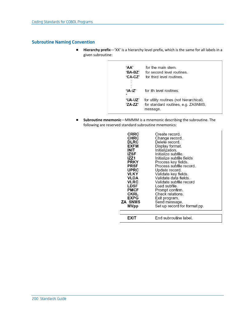
Coding Standards for COBOL Programs
200 Standards Guide
Subroutine Naming Convention
■ Hierarchy prefix—‘XX’ is a hierarchy level prefix, which is the same for all labels in a given subroutine:
■ Subroutine mnemonic—MMMM is a mnemonic describing the subroutine. The following are reserved standard subroutine mnemonics:
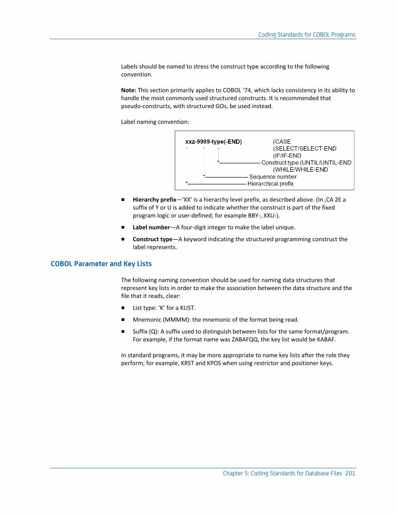
Coding Standards for COBOL Programs
Chapter 5: Coding Standards for Database Files 201
Labels should be named to stress the construct type according to the following convention.
Note: This section primarily applies to COBOL ‘74, which lacks consistency in its ability to handle the most commonly used structured constructs. It is recommended that pseudo-constructs, with structured GOs, be used instead.
Label naming convention:
■ Hierarchy prefix—‘XX’ is a hierarchy level prefix, as described above. (In ,CA 2E a suffix of Y or U is added to indicate whether the construct is part of the fixed program logic or user-defined; for example BBY-, XXU-).
■ Label number—A four-digit integer to make the label unique.
■ Construct type—A keyword indicating the structured programming construct the label represents.
COBOL Parameter and Key Lists
The following naming convention should be used for naming data structures that represent key lists in order to make the association between the data structure and the file that it reads, clear:
■ List type: ‘K’ for a KLIST.
■ Mnemonic (MMMM): the mnemonic of the format being read.
■ Suffix (Q): A suffix used to distinguish between lists for the same format/program. For example, if the format name was ZABAFQQ, the key list would be KABAF.
In standard programs, it may be more appropriate to name key lists after the role they perform; for example, KRST and KPOS when using restrictor and positioner keys.

Coding Standards for COBOL Programs
202 Standards Guide
COBOL Standard Indicators
Use the FILE-STATUS indicators to communicate with files. For each FILE-STATUS value, declare a Level 88 item with a meaningful name. For example, declare level 88 items for use in testing indicators, for example:
■ Use the SET statement to turn indicators on or off, for example:
■ The DDS indicators (01-99, etc.) should be used as little as possible, as they are difficult to reconcile with structured programming. The number of indicators available to program with is in any case fixed, so it is best to reserve their use for the places where you are obliged to use them. Ideally, indicators should only be used to:
– communicate with external files
– handle errors on database files
One method you can use to do this is to declare those most commonly used indicators individually, with those remaining being manipulated, using the above method.
Thus, try to give the same meaning to indicator usage throughout a system. This makes it easier to understand programs. Use specific indicators for functions that are common to many programs, such as function keys, and use a different range of indicators for functions that are specific to a particular program, or part of a program.
Usage of standard indicators in device files should be documented in the device files using the DDS INDTXT, SETOF, CAnn or CFnn keywords. It should not need to be repeated in the COBOL program source.
Comment the use of non-volatile indicators—those which have a gl isl scope rather than a local use; for example ‘IND(87) = Company is insolvent’.
Handling Dates in COBOL
All dates should always be converted to YYMMDD or CYYMMDD format before being output to a database file.
For more information about data handling, refer to the chapter, "General Coding Standards."
Note: All Dates should always be converted to YYMMDD or CYYMMDD format before being output to a database file.
Coding Standards for PL/1 Programs
Chapter 5: Coding Standards for Database Files 203
COBOL Job Name/Operator ID
The user profile name and job name should appear on panels and reports. You should never ‘hard code’ the user profile name as a literal—always get it from the data structure.
Since this information is readily available from the PGMDS of an RPG III program, one technique is to call a standard RPG III subprogram to obtain information about the operator—user profile name, job name, job number.
You should place the program name in a variable. This facilitates renaming or copying the program.
The program data structure may be defined using an externally described file. This helps to standardize its use.
Calculation Checks
When carrying out calculations, always test that a divisor is not zero before dividing with it.
Example of testing divisor value:
■ If a calculation result field for a report or display overflows, fill it with 999s.
■ Unless specifically told not to, always half-adjust when adding together two fields of different precision levels.
Coding Standards for PL/1 Programs
These guidelines are concerned with making programs easy to follow. The section is grouped under the following headings:
■ Program layout—Basic conventions for documentation and spacing.
■ Coding structures—Recommended standard procedures.
■ Naming standards—Conventions for naming variables, formats, fields, procedures, and label names in a consistent manner.
■ Techniques—Date handling, job information, calculation checks.
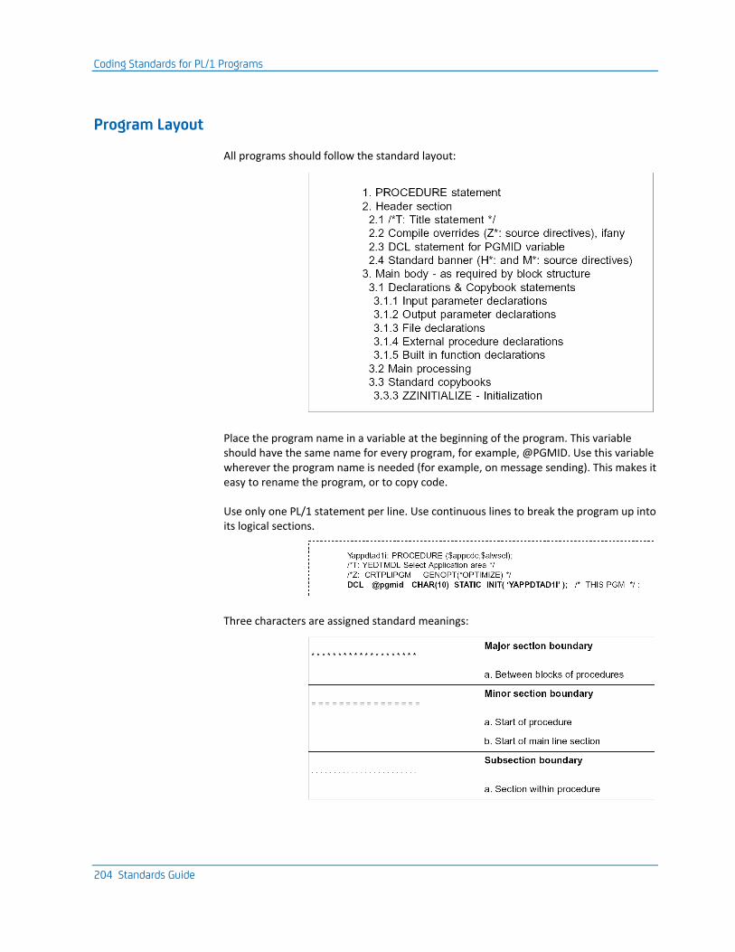
Coding Standards for PL/1 Programs
204 Standards Guide
Program Layout
All programs should follow the standard layout:
Place the program name in a variable at the beginning of the program. This variable should have the same name for every program, for example, @PGMID. Use this variable wherever the program name is needed (for example, on message sending). This makes it easy to rename the program, or to copy code.
Use only one PL/1 statement per line. Use continuous lines to break the program up into its logical sections.
Three characters are assigned standard meanings:
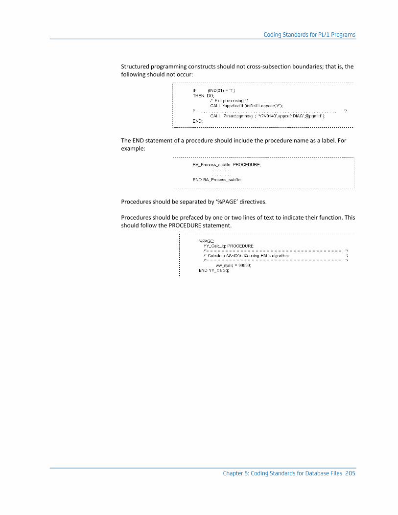
Coding Standards for PL/1 Programs
Chapter 5: Coding Standards for Database Files 205
Structured programming constructs should not cross-subsection boundaries; that is, the following should not occur:
The END statement of a procedure should include the procedure name as a label. For example:
Procedures should be separated by ‘%PAGE’ directives.
Procedures should be prefaced by one or two lines of text to indicate their function. This should follow the PROCEDURE statement.
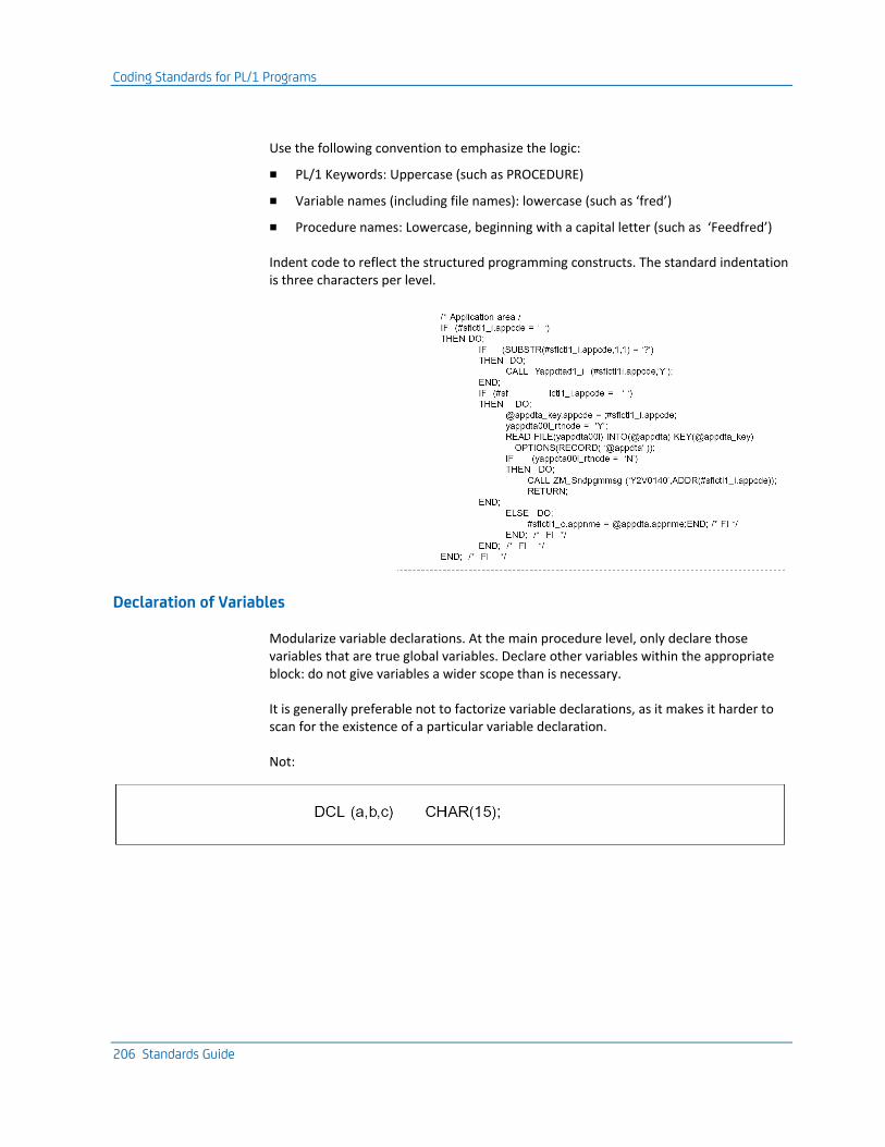
Coding Standards for PL/1 Programs
206 Standards Guide
Use the following convention to emphasize the logic:
■ PL/1 Keywords: Uppercase (such as PROCEDURE)
■ Variable names (including file names): lowercase (such as ‘fred’)
■ Procedure names: Lowercase, beginning with a capital letter (such as ‘Feedfred’)
Indent code to reflect the structured programming constructs. The standard indentation is three characters per level.
Declaration of Variables
Modularize variable declarations. At the main procedure level, only declare those variables that are true global variables. Declare other variables within the appropriate block: do not give variables a wider scope than is necessary.
It is generally preferable not to factorize variable declarations, as it makes it harder to scan for the existence of a particular variable declaration.
Not:
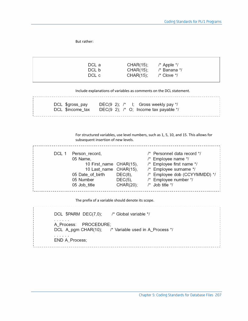
Coding Standards for PL/1 Programs
Chapter 5: Coding Standards for Database Files 207
But rather:
Include explanations of variables as comments on the DCL statement.
For structured variables, use level numbers, such as 1, 5, 10, and 15. This allows for subsequent insertion of new levels.
The prefix of a variable should denote its scope.
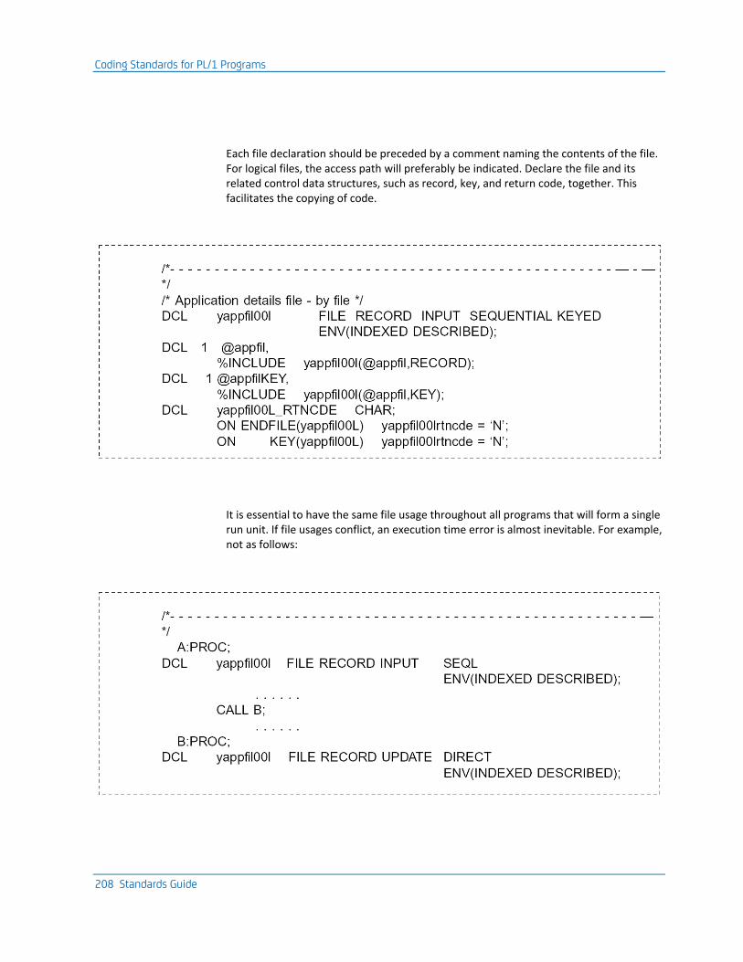
Coding Standards for PL/1 Programs
208 Standards Guide
Each file declaration should be preceded by a comment naming the contents of the file. For logical files, the access path will preferably be indicated. Declare the file and its related control data structures, such as record, key, and return code, together. This facilitates the copying of code.
It is essential to have the same file usage throughout all programs that will form a single run unit. If file usages conflict, an execution time error is almost inevitable. For example, not as follows:
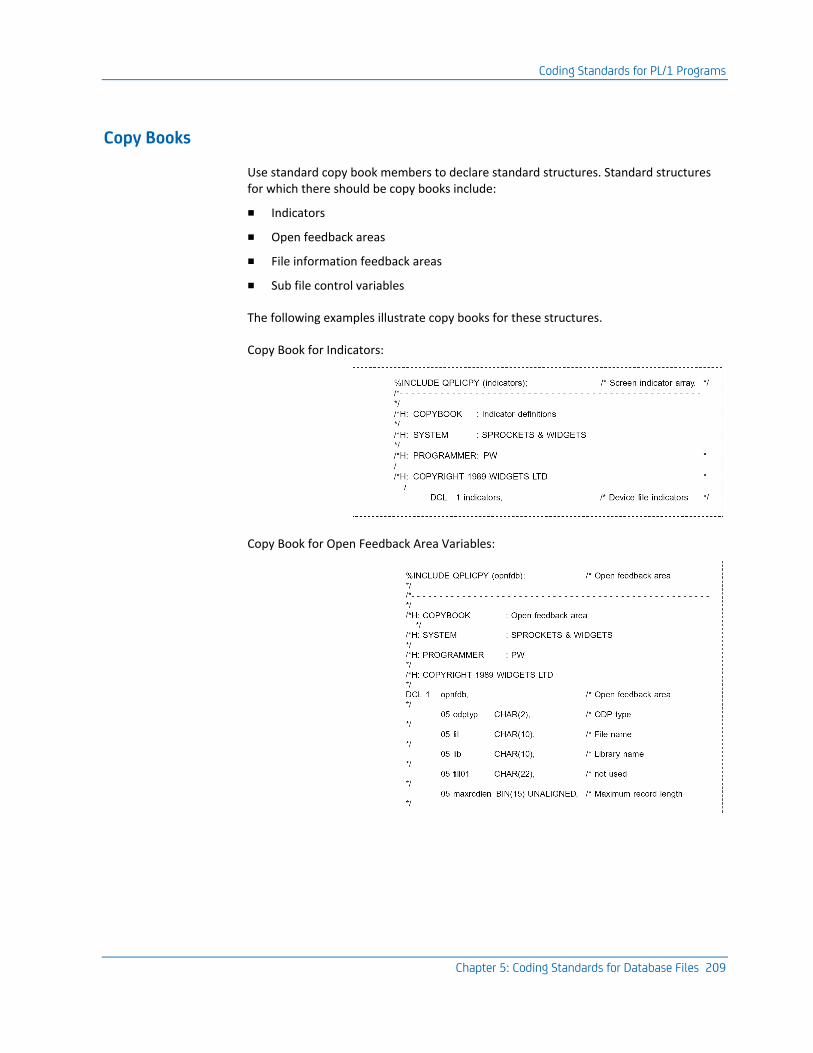
Coding Standards for PL/1 Programs
Chapter 5: Coding Standards for Database Files 209
Copy Books
Use standard copy book members to declare standard structures. Standard structures for which there should be copy books include:
■ Indicators
■ Open feedback areas
■ File information feedback areas
■ Sub file control variables
The following examples illustrate copy books for these structures.
Copy Book for Indicators:
Copy Book for Open Feedback Area Variables:
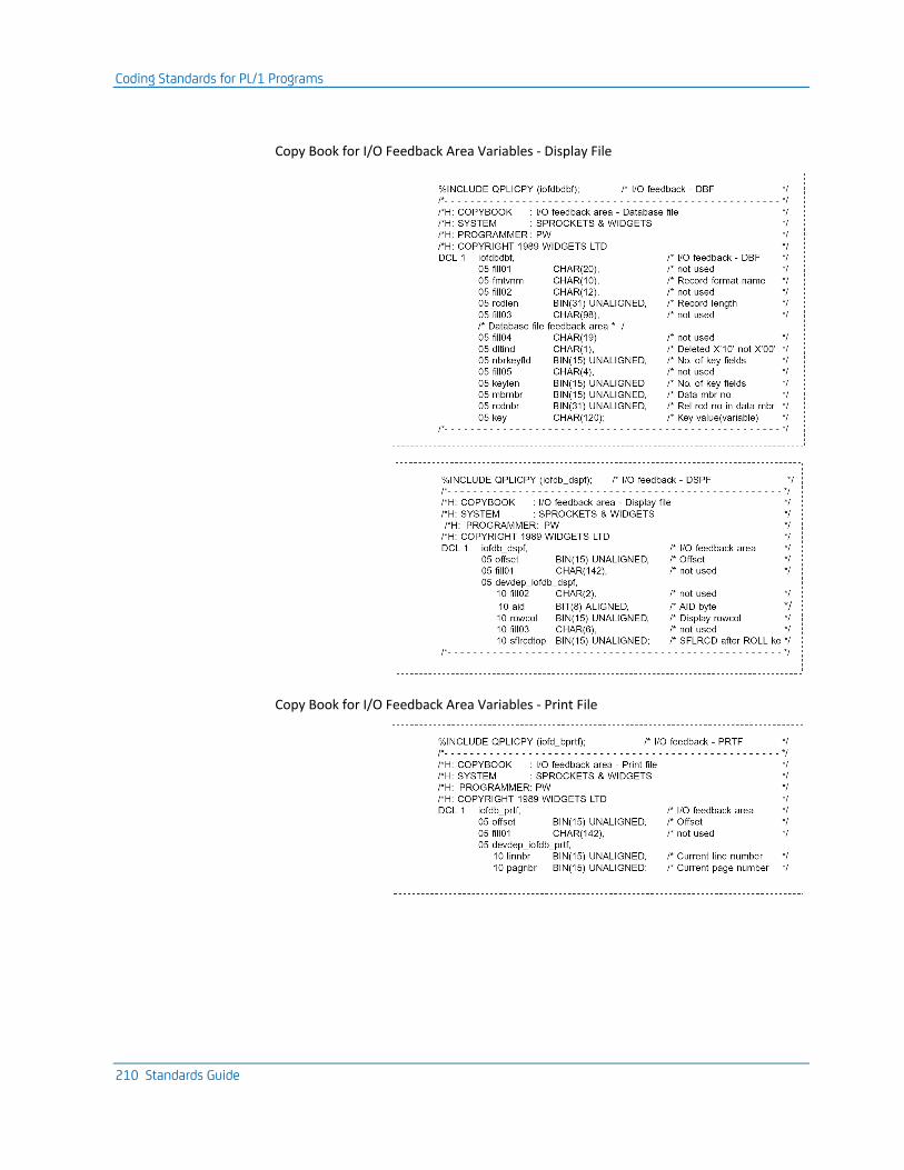
Coding Standards for PL/1 Programs
210 Standards Guide
Copy Book for I/O Feedback Area Variables - Display File
Copy Book for I/O Feedback Area Variables - Print File
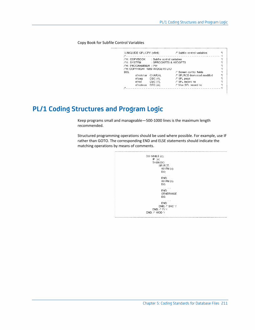
PL/1 Coding Structures and Program Logic
Chapter 5: Coding Standards for Database Files 211
Copy Book for Subfile Control Variables
PL/1 Coding Structures and Program Logic
Keep programs small and manageable—500-1000 lines is the maximum length recommended.
Structured programming operations should be used where possible. For example, use IF rather than GOTO. The corresponding END and ELSE statements should indicate the matching operations by means of comments.
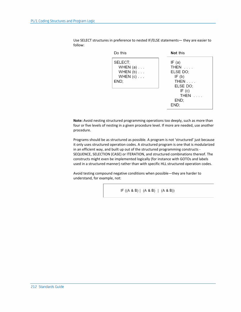
PL/1 Coding Structures and Program Logic
212 Standards Guide
Use SELECT structures in preference to nested IF/ELSE statements— they are easier to follow:
Note: Avoid nesting structured programming operations too deeply, such as more than four or five levels of nesting in a given procedure level. If more are needed, use another procedure.
Programs should be as structured as possible. A program is not ‘structured’ just because it only uses structured operation codes. A structured program is one that is modularized in an efficient way, and built up out of the structured programming constructs - SEQUENCE, SELECTION (CASE) or ITERATION, and structured combinations thereof. The constructs might even be implemented logically (for instance with GOTOs and labels used in a structured manner) rather than with specific HLL structured operation codes.
Avoid testing compound negative conditions when possible—they are harder to understand, for example, not:
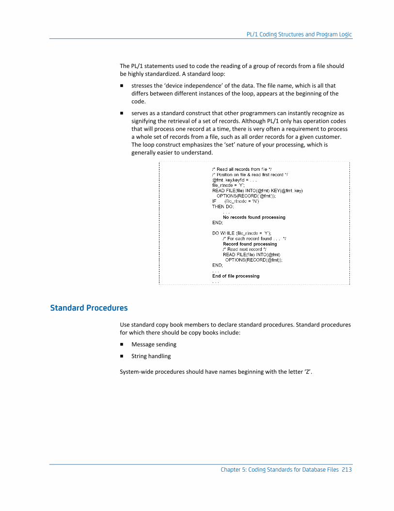
PL/1 Coding Structures and Program Logic
Chapter 5: Coding Standards for Database Files 213
The PL/1 statements used to code the reading of a group of records from a file should be highly standardized. A standard loop:
■ stresses the ‘device independence’ of the data. The file name, which is all that differs between different instances of the loop, appears at the beginning of the code.
■ serves as a standard construct that other programmers can instantly recognize as signifying the retrieval of a set of records. Although PL/1 only has operation codes that will process one record at a time, there is very often a requirement to process a whole set of records from a file, such as all order records for a given customer. The loop construct emphasizes the ‘set’ nature of your processing, which is generally easier to understand.
Standard Procedures
Use standard copy book members to declare standard procedures. Standard procedures for which there should be copy books include:
■ Message sending
■ String handling
System-wide procedures should have names beginning with the letter ‘Z’.
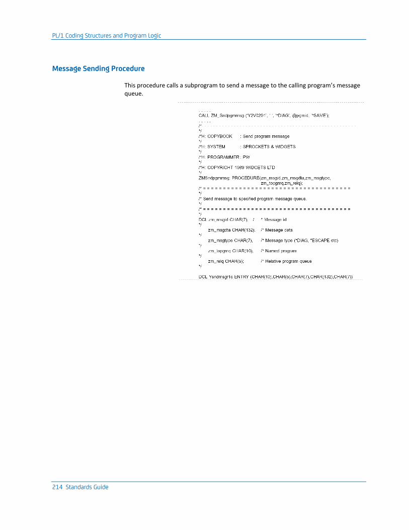
PL/1 Coding Structures and Program Logic
214 Standards Guide
Message Sending Procedure
This procedure calls a subprogram to send a message to the calling program’s message queue.
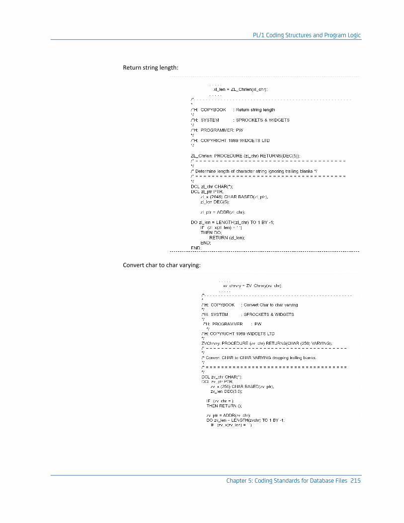
PL/1 Coding Structures and Program Logic
Chapter 5: Coding Standards for Database Files 215
Return string length:
Convert char to char varying:
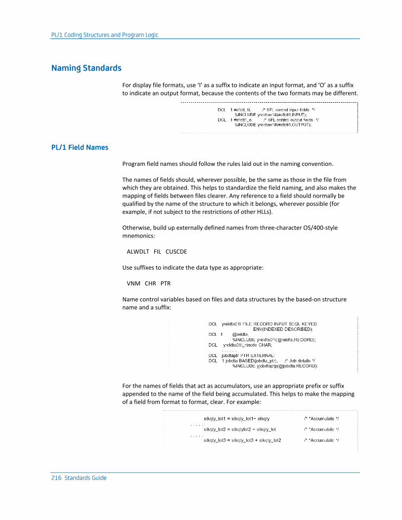
PL/1 Coding Structures and Program Logic
216 Standards Guide
Naming Standards
For display file formats, use ‘I’ as a suffix to indicate an input format, and ‘O’ as a suffix to indicate an output format, because the contents of the two formats may be different.
PL/1 Field Names
Program field names should follow the rules laid out in the naming convention.
The names of fields should, wherever possible, be the same as those in the file from which they are obtained. This helps to standardize the field naming, and also makes the mapping of fields between files clearer. Any reference to a field should normally be qualified by the name of the structure to which it belongs, wherever possible (for example, if not subject to the restrictions of other HLLs).
Otherwise, build up externally defined names from three-character OS/400-style mnemonics:
ALWDLT FIL CUSCDE
Use suffixes to indicate the data type as appropriate:
VNM CHR PTR
Name control variables based on files and data structures by the based-on structure name and a suffix:
For the names of fields that act as accumulators, use an appropriate prefix or suffix appended to the name of the field being accumulated. This helps to make the mapping of a field from format to format, clear. For example:
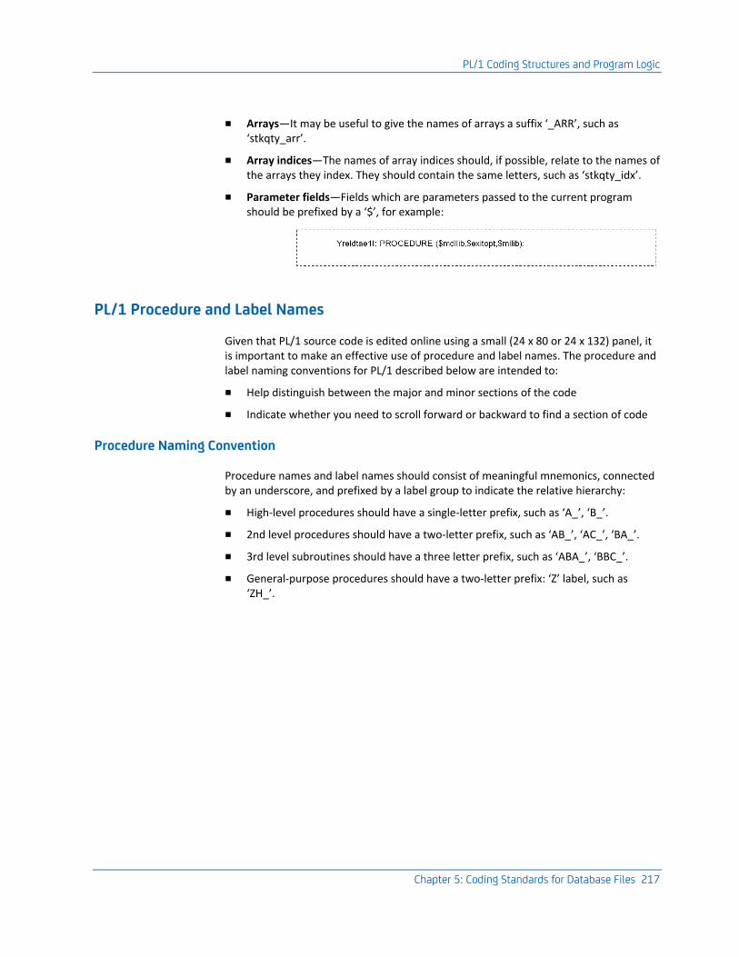
PL/1 Coding Structures and Program Logic
Chapter 5: Coding Standards for Database Files 217
■ Arrays—It may be useful to give the names of arrays a suffix ‘_ARR’, such as ‘stkqty_arr’.
■ Array indices—The names of array indices should, if possible, relate to the names of the arrays they index. They should contain the same letters, such as ‘stkqty_idx’.
■ Parameter fields—Fields which are parameters passed to the current program should be prefixed by a ‘$’, for example:
PL/1 Procedure and Label Names
Given that PL/1 source code is edited online using a small (24 x 80 or 24 x 132) panel, it is important to make an effective use of procedure and label names. The procedure and label naming conventions for PL/1 described below are intended to:
■ Help distinguish between the major and minor sections of the code
■ Indicate whether you need to scroll forward or backward to find a section of code
Procedure Naming Convention
Procedure names and label names should consist of meaningful mnemonics, connected by an underscore, and prefixed by a label group to indicate the relative hierarchy:
■ High-level procedures should have a single-letter prefix, such as ‘A_’, ‘B_’.
■ 2nd level procedures should have a two-letter prefix, such as ‘AB_’, ‘AC_’, ‘BA_’.
■ 3rd level subroutines should have a three letter prefix, such as ‘ABA_’, ‘BBC_’.
■ General-purpose procedures should have a two-letter prefix: ‘Z’ label, such as ‘ZH_’.
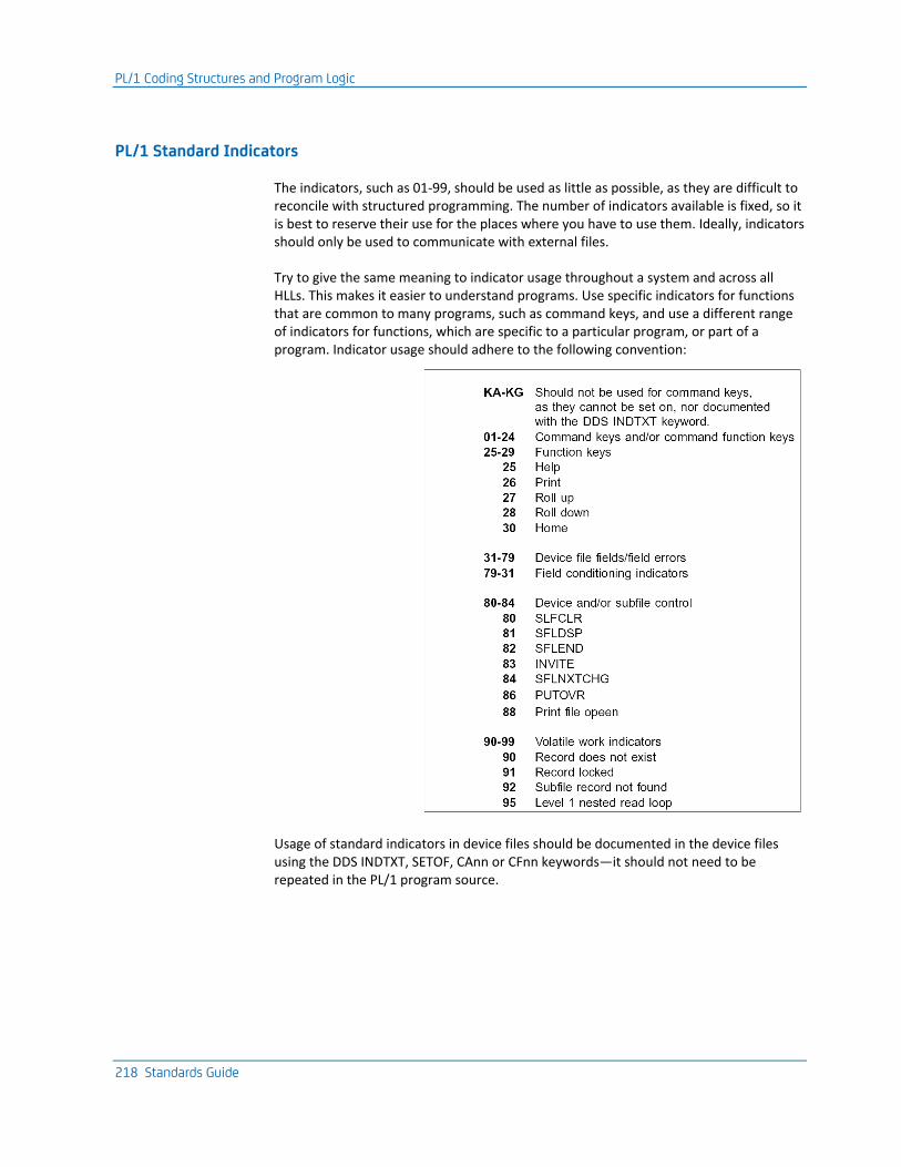
PL/1 Coding Structures and Program Logic
218 Standards Guide
PL/1 Standard Indicators
The indicators, such as 01-99, should be used as little as possible, as they are difficult to reconcile with structured programming. The number of indicators available is fixed, so it is best to reserve their use for the places where you have to use them. Ideally, indicators should only be used to communicate with external files.
Try to give the same meaning to indicator usage throughout a system and across all HLLs. This makes it easier to understand programs. Use specific indicators for functions that are common to many programs, such as command keys, and use a different range of indicators for functions, which are specific to a particular program, or part of a program. Indicator usage should adhere to the following convention:
Usage of standard indicators in device files should be documented in the device files using the DDS INDTXT, SETOF, CAnn or CFnn keywords—it should not need to be repeated in the PL/1 program source.
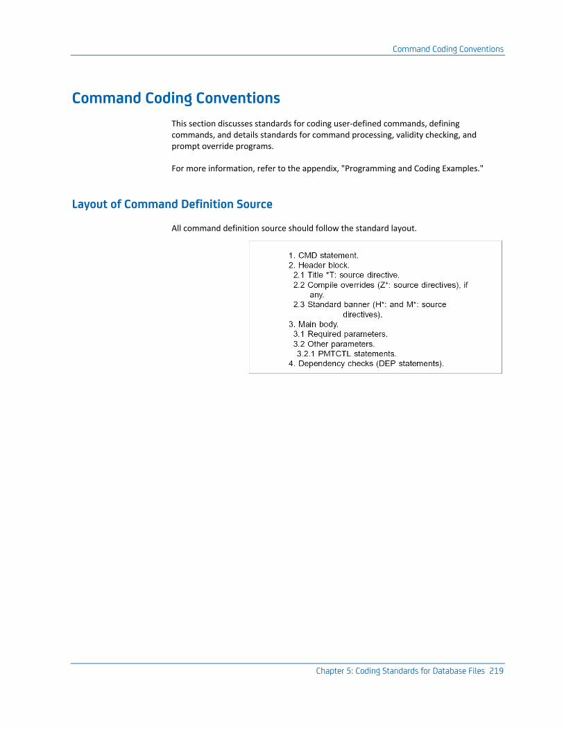
Command Coding Conventions
Chapter 5: Coding Standards for Database Files 219
Command Coding Conventions
This section discusses standards for coding user-defined commands, defining commands, and details standards for command processing, validity checking, and prompt override programs.
For more information, refer to the appendix, "Programming and Coding Examples."
Layout of Command Definition Source
All command definition source should follow the standard layout.
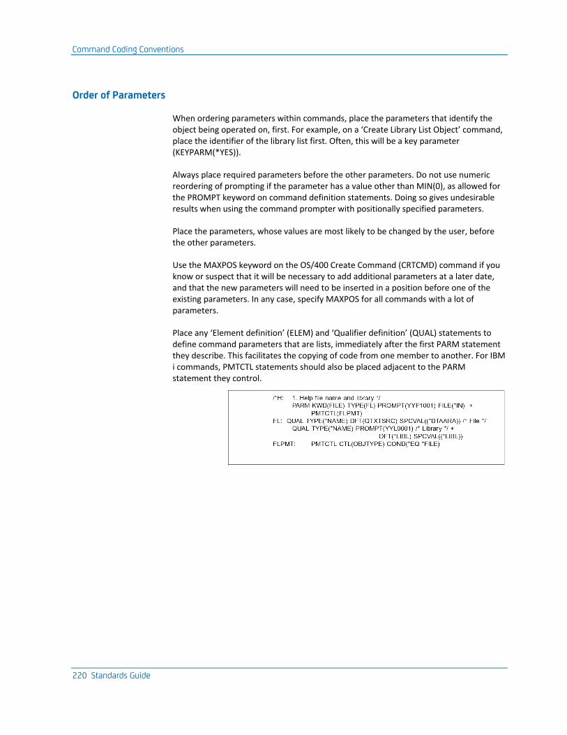
Command Coding Conventions
220 Standards Guide
Order of Parameters
When ordering parameters within commands, place the parameters that identify the object being operated on, first. For example, on a ‘Create Library List Object’ command, place the identifier of the library list first. Often, this will be a key parameter (KEYPARM(*YES)).
Always place required parameters before the other parameters. Do not use numeric reordering of prompting if the parameter has a value other than MIN(0), as allowed for the PROMPT keyword on command definition statements. Doing so gives undesirable results when using the command prompter with positionally specified parameters.
Place the parameters, whose values are most likely to be changed by the user, before the other parameters.
Use the MAXPOS keyword on the OS/400 Create Command (CRTCMD) command if you know or suspect that it will be necessary to add additional parameters at a later date, and that the new parameters will need to be inserted in a position before one of the existing parameters. In any case, specify MAXPOS for all commands with a lot of parameters.
Place any ‘Element definition’ (ELEM) and ‘Qualifier definition’ (QUAL) statements to define command parameters that are lists, immediately after the first PARM statement they describe. This facilitates the copying of code from one member to another. For IBM i commands, PMTCTL statements should also be placed adjacent to the PARM statement they control.
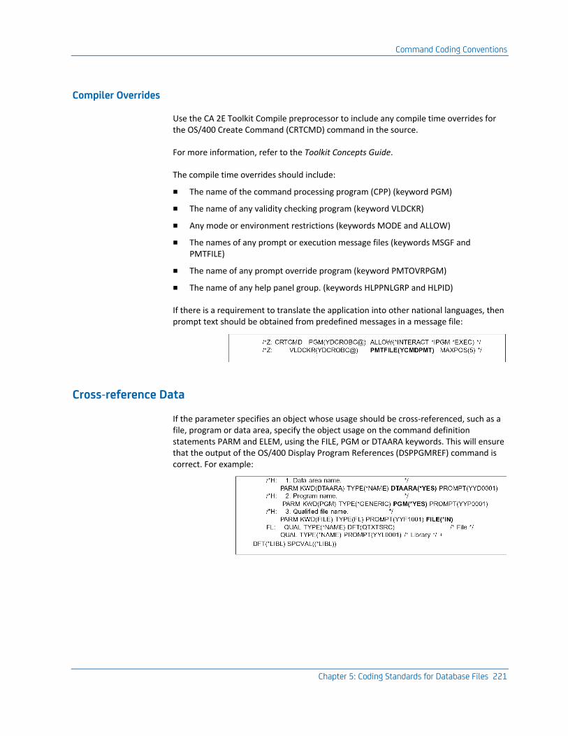
Command Coding Conventions
Chapter 5: Coding Standards for Database Files 221
Compiler Overrides
Use the CA 2E Toolkit Compile preprocessor to include any compile time overrides for the OS/400 Create Command (CRTCMD) command in the source.
For more information, refer to the Toolkit Concepts Guide.
The compile time overrides should include:
■ The name of the command processing program (CPP) (keyword PGM)
■ The name of any validity checking program (keyword VLDCKR)
■ Any mode or environment restrictions (keywords MODE and ALLOW)
■ The names of any prompt or execution message files (keywords MSGF and PMTFILE)
■ The name of any prompt override program (keyword PMTOVRPGM)
■ The name of any help panel group. (keywords HLPPNLGRP and HLPID)
If there is a requirement to translate the application into other national languages, then prompt text should be obtained from predefined messages in a message file:
Cross-reference Data
If the parameter specifies an object whose usage should be cross-referenced, such as a file, program or data area, specify the object usage on the command definition statements PARM and ELEM, using the FILE, PGM or DTAARA keywords. This will ensure that the output of the OS/400 Display Program References (DSPPGMREF) command is correct. For example:
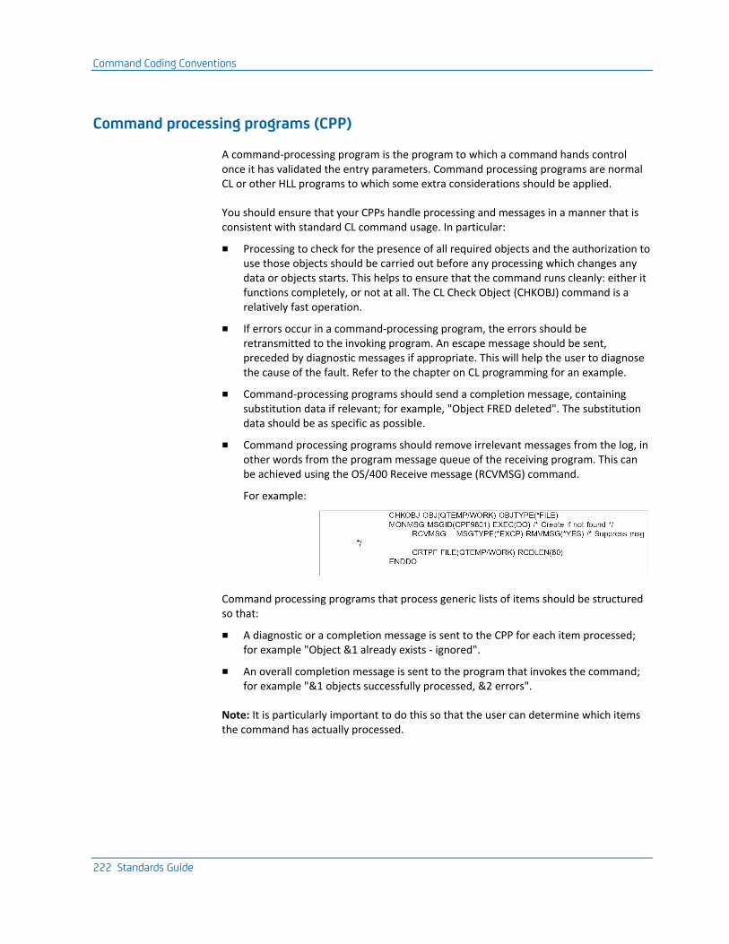
Command Coding Conventions
222 Standards Guide
Command processing programs (CPP)
A command-processing program is the program to which a command hands control once it has validated the entry parameters. Command processing programs are normal CL or other HLL programs to which some extra considerations should be applied.
You should ensure that your CPPs handle processing and messages in a manner that is consistent with standard CL command usage. In particular:
■ Processing to check for the presence of all required objects and the authorization to use those objects should be carried out before any processing which changes any data or objects starts. This helps to ensure that the command runs cleanly: either it functions completely, or not at all. The CL Check Object (CHKOBJ) command is a relatively fast operation.
■ If errors occur in a command-processing program, the errors should be retransmitted to the invoking program. An escape message should be sent, preceded by diagnostic messages if appropriate. This will help the user to diagnose the cause of the fault. Refer to the chapter on CL programming for an example.
■ Command-processing programs should send a completion message, containing substitution data if relevant; for example, "Object FRED deleted". The substitution data should be as specific as possible.
■ Command processing programs should remove irrelevant messages from the log, in other words from the program message queue of the receiving program. This can be achieved using the OS/400 Receive message (RCVMSG) command.
For example:
Command processing programs that process generic lists of items should be structured so that:
■ A diagnostic or a completion message is sent to the CPP for each item processed; for example "Object &1 already exists - ignored".
■ An overall completion message is sent to the program that invokes the command; for example "&1 objects successfully processed, &2 errors".
Note: It is particularly important to do this so that the user can determine which items the command has actually processed.

Command Coding Conventions
Chapter 5: Coding Standards for Database Files 223
Command Validity Checking Programs
A validity-checking program is a user-defined subprogram, which can be associated with a user-defined command. The validity checker will be called by the final stage of execution of the OS/400 command prompter, before it hands over control to the CPP—it can be used to carry out any user-defined validation of the command parameters.
If used at all, validity checking programs should only carry out limited validation; for instance, any cross-checking of parameters that cannot be achieved with the CL ‘Dependency definition’ (DEP) command definition statement. This should only be necessary when checking the components of lists and qualified names.
Validity checkers should not check for the existence of objects or other entities, nor should they be used to invoke selection functions. This is because the validity checker is invoked whenever the OS/400 command prompter or syntax checker is invoked for the command, even if the command is not executed.
Validity checking programs should resend diagnostics, using the standard OS/400 message - CPD0006 in QCPFMSG.
If validity checking fails, the errors should be retransmitted to the invoking program (which is always the command prompter) as diagnostics; and an escape message (CPF0002) should be sent to return control.
Example of code to resend a diagnostic to the prompter:
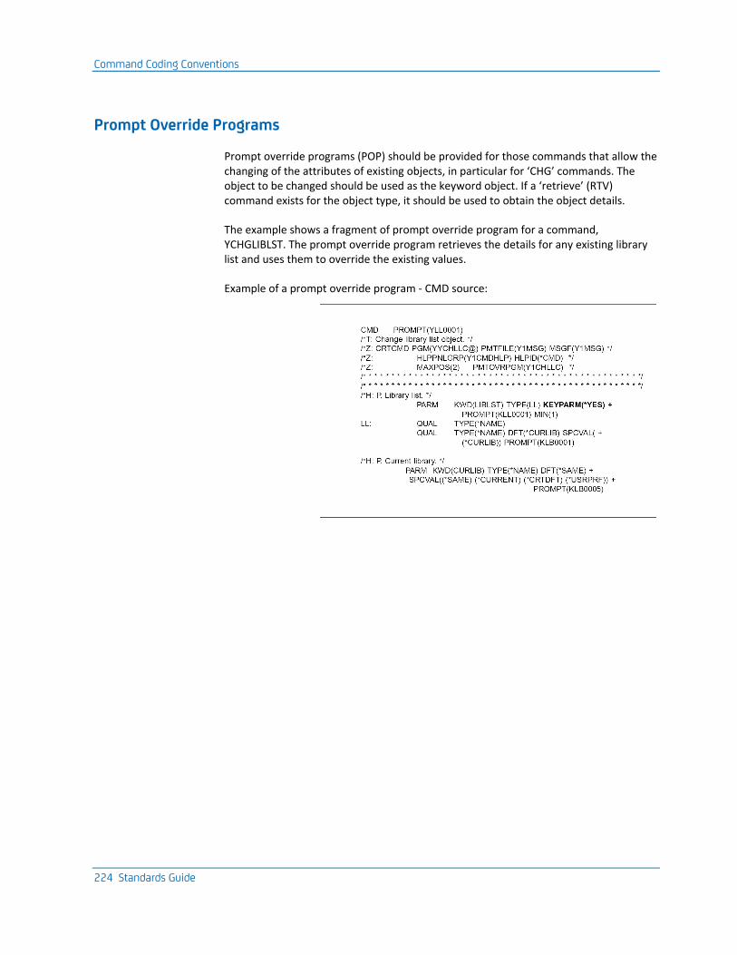
Command Coding Conventions
224 Standards Guide
Prompt Override Programs
Prompt override programs (POP) should be provided for those commands that allow the changing of the attributes of existing objects, in particular for ‘CHG’ commands. The object to be changed should be used as the keyword object. If a ‘retrieve’ (RTV) command exists for the object type, it should be used to obtain the object details.
The example shows a fragment of prompt override program for a command, YCHGLIBLST. The prompt override program retrieves the details for any existing library list and uses them to override the existing values.
Example of a prompt override program - CMD source:
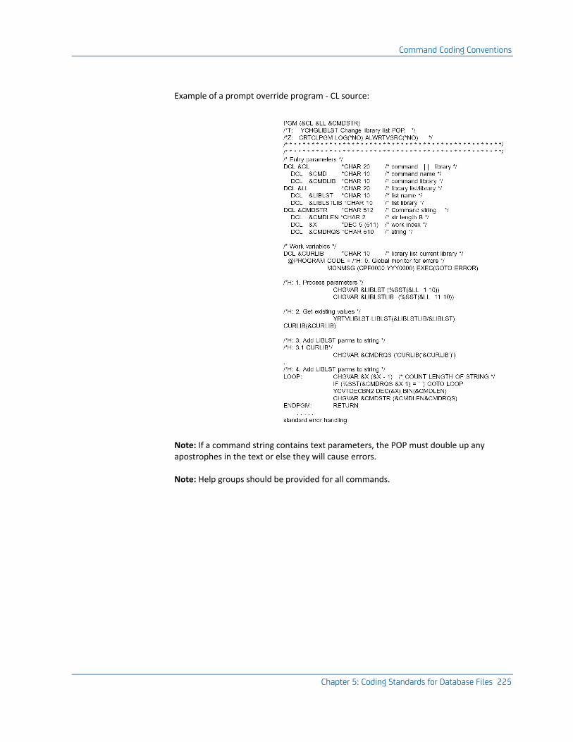
Command Coding Conventions
Chapter 5: Coding Standards for Database Files 225
Example of a prompt override program - CL source:
Note: If a command string contains text parameters, the POP must double up any apostrophes in the text or else they will cause errors.
Note: Help groups should be provided for all commands.
Coding Standards for Messages
226 Standards Guide
Coding Standards for Messages
This section describes design and coding standards for messages. It explains how messages are used and provides standards for defining and sending messages.
The midrange architecture has fast, sophisticated message handling facilities you can use to send and receive messages in your own HLL programs. Messages can be used both as an invocation/return control mechanism and to handle text. This section mainly considers the latter.
OS/400 message descriptions provide a program - independent mechanism for storing natural language text fragments, thus making it possible to translate a system without changing the non-text objects in a system. When you build an application, you can use OS/400 messages in two different ways:
■ As prompt messages: The text prompts used on commands, menus, panels, and reports, can all be isolated from the device file and command source and stored as external message definitions. Prompt messages normally only require first level text. (You may use the second level text for notes for translators).
■ As execution messages: Execution messages are sent and received at execution. They both provide a control mechanism to determine the subsequent processing and can be used to provide the user with a natural language explanation of what has taken place or has gone wrong. They may have substitution variables and second level text.
Prompt Messages
Prompt messages are used to enable translation of the text into other National Languages and also to ensure consistency in the use of a given term. In particular you will want to ensure that the prompt used in panels and in help text corresponds exactly.
Coding Standards for Messages
Chapter 5: Coding Standards for Database Files 227
Prompt Types
There are a number of different types of text element that make up UIS conformant panels. You should ensure that each type follows the correct UIS standards for its type. See the sections on design and coding for each object type for further information on the rules.
The following is a summary of the different types of prompt commonly found in an application:
■ Commands
■ Command titles. Capitalized.
■ Command parameter prompts. First letter capitalized.
■ Panel elements
■ Panel titles. Capitalized, centered.
■ Panel top instructions. There are a number of standard formulations, for example, ‘Type choices, press Enter’. Set up standard definitions and reuse them where possible.
■ Panel options. This should follow UIS layout standards (for example 4=Delete). Do not attempt to reuse messages but instead, provide a separate message for each display. Use a single message for the whole line—this makes it easier for translators to abbreviate.
■ Panel column headings. Again, do not attempt to reuse messages but instead provide a separate message for each display. Use a single message for the whole line—this makes it easier for translators to abbreviate.
■ Field labels. Use an initial capital and pad any trailing blanks with periods. Do not use a ‘:’ Hard code it in the DDS.
■ Field right hand side text. Capitalized, punctuated by commas.
There are a number of frequently occurring items (for example "Name, F4 for list"), which should be set up centrally and reused when possible.
■ Function key instructions. This should follow UIS layout standards (for example, F3=Exit). Do not attempt to reuse messages but instead, provide a separate message for each display. Use a single message for the whole line.
■ Help text
■ Panel titles. Use the panel title with "- Help" appended. (Use the UIM &msg facility to define ("Help") as a reusable message.
■ Extended headings. Use the field labels prompts for the headings that appear in extended help display (UIM ‘:XH3’ tag).
■ Panel options. Use standard messages for each function key label ("Delete", "Change", "Rename", etc.).
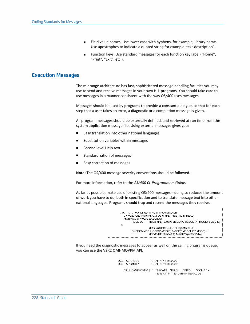
Coding Standards for Messages
228 Standards Guide
■ Field value names. Use lower case with hyphens, for example, library-name. Use apostrophes to indicate a quoted string for example ‘text-description’.
■ Function keys. Use standard messages for each function key label ("Home", "Print", "Exit", etc.).
Execution Messages
The midrange architecture has fast, sophisticated message handling facilities you may use to send and receive messages in your own HLL programs. You should take care to use messages in a manner consistent with the way OS/400 uses messages.
Messages should be used by programs to provide a constant dialogue, so that for each step that a user takes an error, a diagnostic or a completion message is given.
All program messages should be externally defined, and retrieved at run time from the system application message file. Using external messages gives you:
■ Easy translation into other national languages
■ Substitution variables within messages
■ Second level Help text
■ Standardization of messages
■ Easy correction of messages
Note: The OS/400 message severity conventions should be followed.
For more information, refer to the AS/400 CL Programmers Guide.
As far as possible, make use of existing OS/400 messages—doing so reduces the amount of work you have to do, both in specification and to translate message text into other national languages. Programs should trap and resend the messages they receive.
If you need the diagnostic messages to appear as well on the calling programs queue, you can use the V2R2 QMHMOVPM API.

Coding Standards for Messages
Chapter 5: Coding Standards for Database Files 229
Message substitution variables should be used where helpful—they can be particularly useful in conjunction with input capable subfiles, as the variables can be used to distinguish which line in the subfile is in error. For example, on a subfile panel that shows many products, ‘Product code &1 not found’ (where &1 is the missing product) will be more useful than just ‘Product code not found’.
Add message:
Use in program:
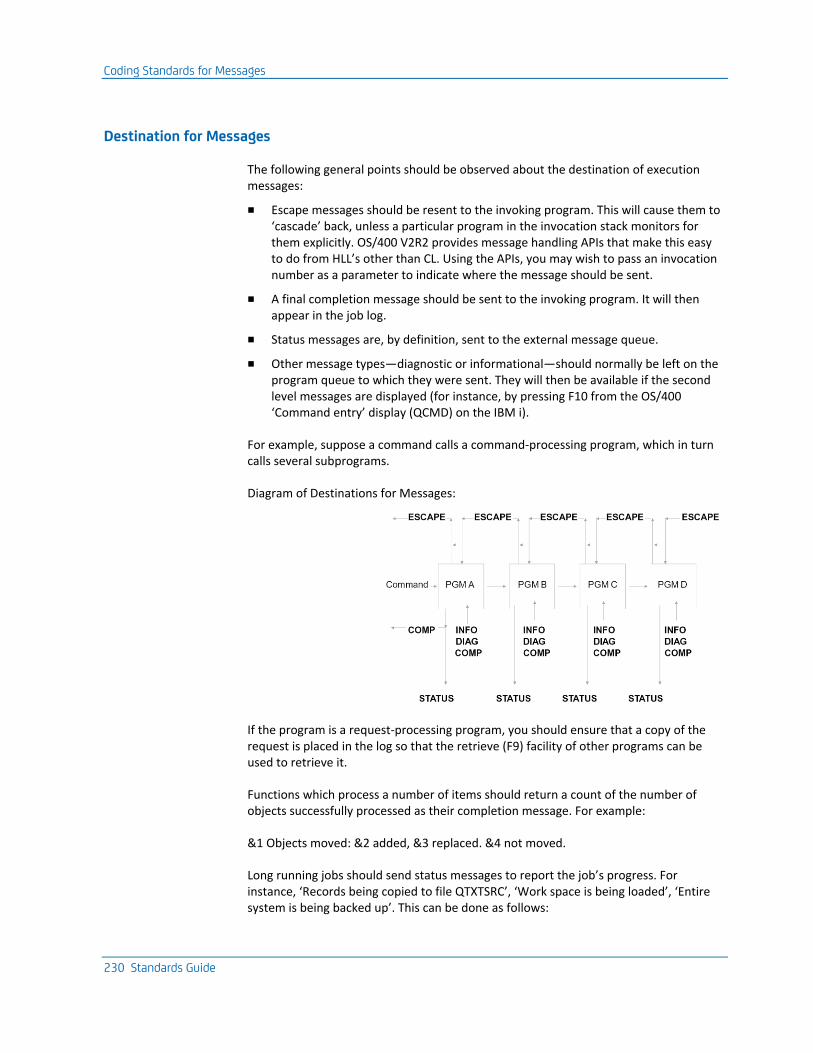
Coding Standards for Messages
230 Standards Guide
Destination for Messages
The following general points should be observed about the destination of execution messages:
■ Escape messages should be resent to the invoking program. This will cause them to ‘cascade’ back, unless a particular program in the invocation stack monitors for them explicitly. OS/400 V2R2 provides message handling APIs that make this easy to do from HLL’s other than CL. Using the APIs, you may wish to pass an invocation number as a parameter to indicate where the message should be sent.
■ A final completion message should be sent to the invoking program. It will then appear in the job log.
■ Status messages are, by definition, sent to the external message queue.
■ Other message types—diagnostic or informational—should normally be left on the program queue to which they were sent. They will then be available if the second level messages are displayed (for instance, by pressing F10 from the OS/400 ‘Command entry’ display (QCMD) on the IBM i).
For example, suppose a command calls a command-processing program, which in turn calls several subprograms.
Diagram of Destinations for Messages:
If the program is a request-processing program, you should ensure that a copy of the request is placed in the log so that the retrieve (F9) facility of other programs can be used to retrieve it.
Functions which process a number of items should return a count of the number of objects successfully processed as their completion message. For example:
&1 Objects moved: &2 added, &3 replaced. &4 not moved.
Long running jobs should send status messages to report the job’s progress. For instance, ‘Records being copied to file QTXTSRC’, ‘Work space is being loaded’, ‘Entire system is being backed up’. This can be done as follows:
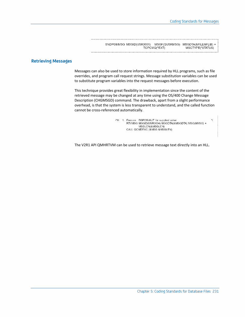
Coding Standards for Messages
Chapter 5: Coding Standards for Database Files 231
Retrieving Messages
Messages can also be used to store information required by HLL programs, such as file overrides, and program call request strings. Message substitution variables can be used to substitute program variables into the request messages before execution.
This technique provides great flexibility in implementation since the content of the retrieved message may be changed at any time using the OS/400 Change Message Description (CHGMSGD) command. The drawback, apart from a slight performance overhead, is that the system is less transparent to understand, and the called function cannot be cross-referenced automatically.
The V2R1 API QMHRTVM can be used to retrieve message text directly into an HLL.
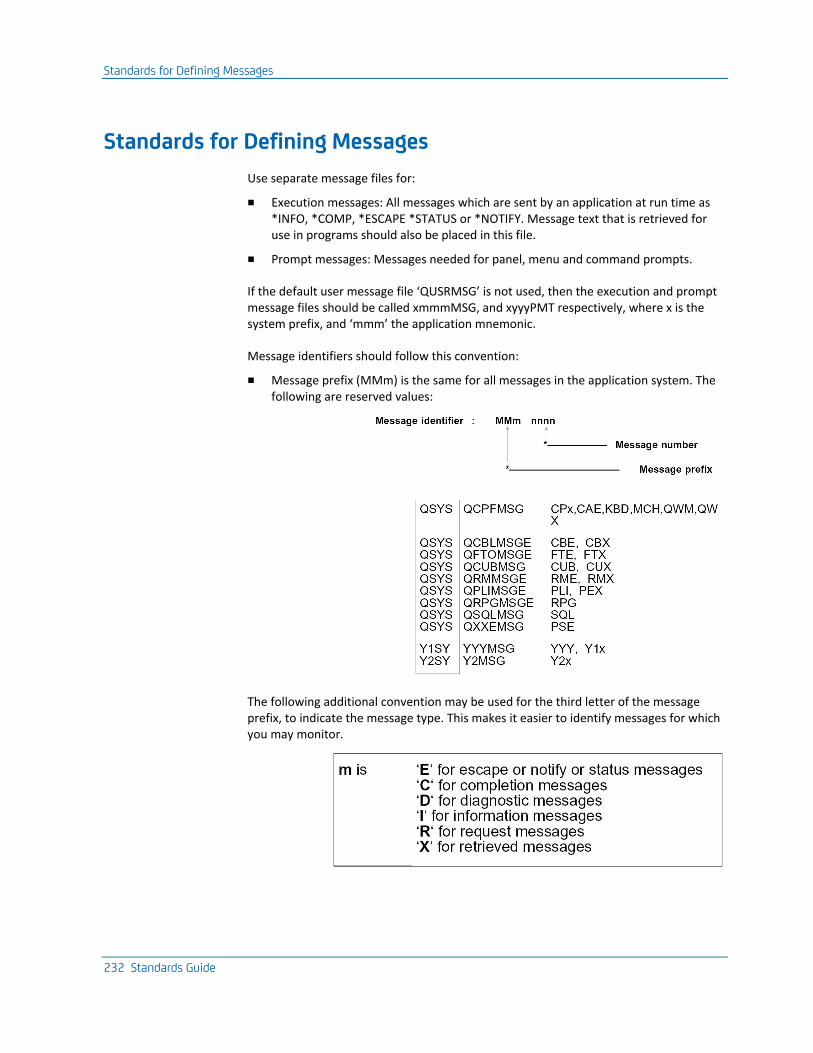
Standards for Defining Messages
232 Standards Guide
Standards for Defining Messages
Use separate message files for:
■ Execution messages: All messages which are sent by an application at run time as *INFO, *COMP, *ESCAPE *STATUS or *NOTIFY. Message text that is retrieved for use in programs should also be placed in this file.
■ Prompt messages: Messages needed for panel, menu and command prompts.
If the default user message file ‘QUSRMSG’ is not used, then the execution and prompt message files should be called xmmmMSG, and xyyyPMT respectively, where x is the system prefix, and ‘mmm’ the application mnemonic.
Message identifiers should follow this convention:
■ Message prefix (MMm) is the same for all messages in the application system. The following are reserved values:
The following additional convention may be used for the third letter of the message prefix, to indicate the message type. This makes it easier to identify messages for which you may monitor.
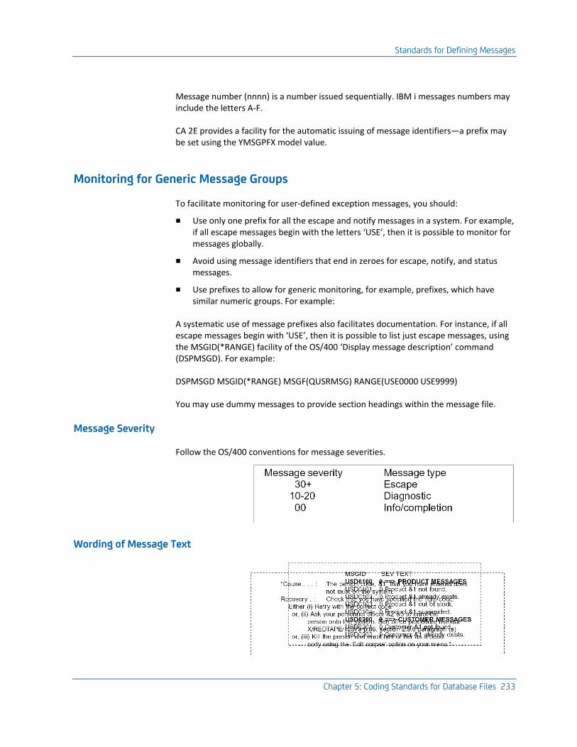
Standards for Defining Messages
Chapter 5: Coding Standards for Database Files 233
Message number (nnnn) is a number issued sequentially. IBM i messages numbers may include the letters A-F.
CA 2E provides a facility for the automatic issuing of message identifiers—a prefix may be set using the YMSGPFX model value.
Monitoring for Generic Message Groups
To facilitate monitoring for user-defined exception messages, you should:
■ Use only one prefix for all the escape and notify messages in a system. For example, if all escape messages begin with the letters ‘USE’, then it is possible to monitor for messages globally.
■ Avoid using message identifiers that end in zeroes for escape, notify, and status messages.
■ Use prefixes to allow for generic monitoring, for example, prefixes, which have similar numeric groups. For example:
A systematic use of message prefixes also facilitates documentation. For instance, if all escape messages begin with ‘USE’, then it is possible to list just escape messages, using the MSGID(*RANGE) facility of the OS/400 ‘Display message description’ command (DSPMSGD). For example:
DSPMSGD MSGID(*RANGE) MSGF(QUSRMSG) RANGE(USE0000 USE9999)
You may use dummy messages to provide section headings within the message file.
Message Severity
Follow the OS/400 conventions for message severities.
Wording of Message Text
Standards for Defining Messages
234 Standards Guide
First Level
The first level text of a message should give a concise statement of what is wrong or what has happened. A substitution variable can be used to relate the message to a particular entered value. For example:
"Invalid person code &1 entered"
On IBM i, messages should be given in the form "A in B"; for example, "Object &1 not found in library &2".
Second Level
The second level text of error messages (escape, diagnostic, or notify) should give a more detailed explanation of the cause of the error, suggest possible methods of recovery, and if appropriate, any additional sources of information. The key words ‘Cause’, and ‘Recovery’ should be used to indicate the start of the respective sections. Messages should be formatted using the &N and &B facilities to indent or start text on a new line.
Editing Existing Messages
OS/400 includes a command that enables you to edit the text and other attributes of an existing message. See the IBM i Change Message Description (CHGMSGD). The OS/400 Merge Message File (MRGMSGF) command can be used to carry out a limited copying of messages. There is also a CA 2E Toolkit command to copy a message description, Copy Message Description (YCPYMSGD).
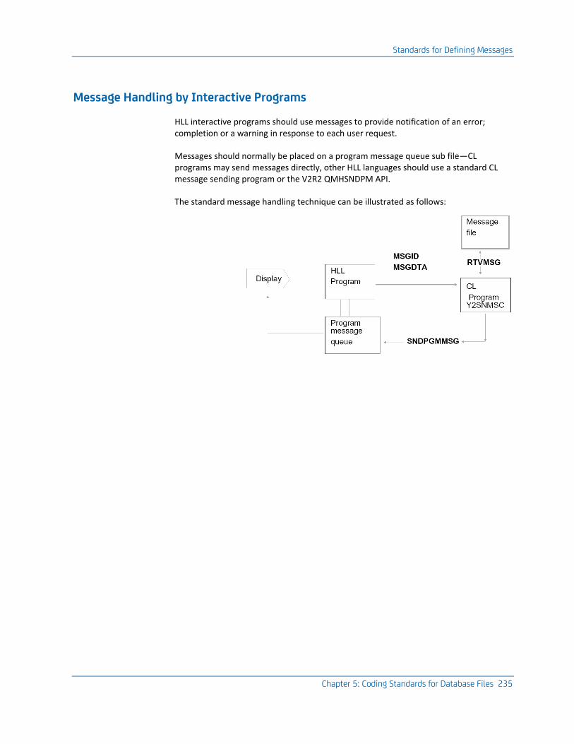
Standards for Defining Messages
Chapter 5: Coding Standards for Database Files 235
Message Handling by Interactive Programs
HLL interactive programs should use messages to provide notification of an error; completion or a warning in response to each user request.
Messages should normally be placed on a program message queue sub file—CL programs may send messages directly, other HLL languages should use a standard CL message sending program or the V2R2 QMHSNDPM API.
The standard message handling technique can be illustrated as follows:
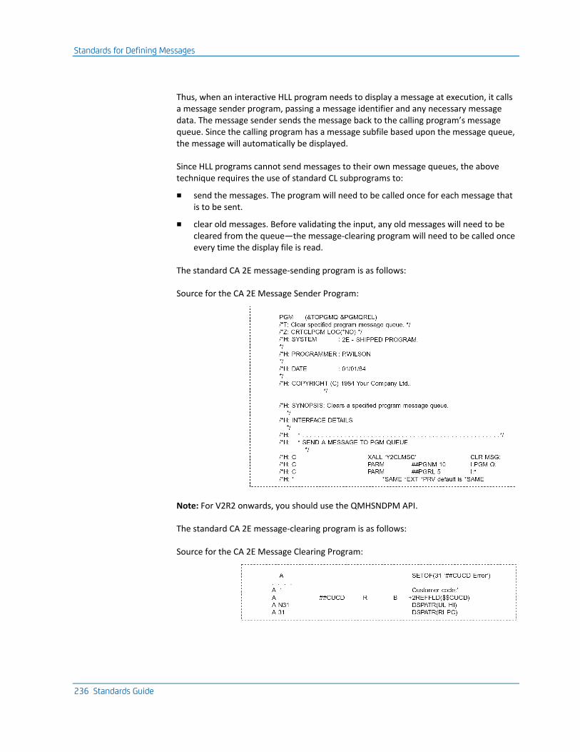
Standards for Defining Messages
236 Standards Guide
Thus, when an interactive HLL program needs to display a message at execution, it calls a message sender program, passing a message identifier and any necessary message data. The message sender sends the message back to the calling program’s message queue. Since the calling program has a message subfile based upon the message queue, the message will automatically be displayed.
Since HLL programs cannot send messages to their own message queues, the above technique requires the use of standard CL subprograms to:
■ send the messages. The program will need to be called once for each message that is to be sent.
■ clear old messages. Before validating the input, any old messages will need to be cleared from the queue—the message-clearing program will need to be called once every time the display file is read.
The standard CA 2E message-sending program is as follows:
Source for the CA 2E Message Sender Program:
Note: For V2R2 onwards, you should use the QMHSNDPM API.
The standard CA 2E message-clearing program is as follows:
Source for the CA 2E Message Clearing Program:
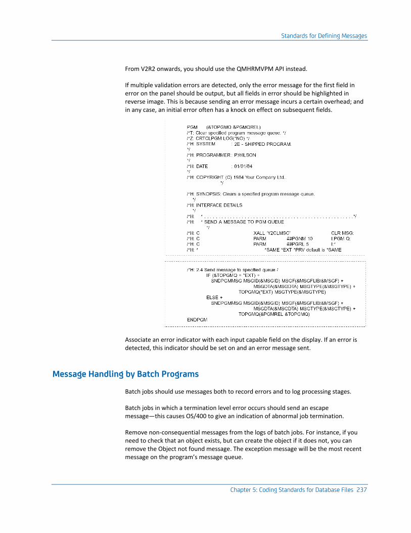
Standards for Defining Messages
Chapter 5: Coding Standards for Database Files 237
From V2R2 onwards, you should use the QMHRMVPM API instead.
If multiple validation errors are detected, only the error message for the first field in error on the panel should be output, but all fields in error should be highlighted in reverse image. This is because sending an error message incurs a certain overhead; and in any case, an initial error often has a knock on effect on subsequent fields.
Associate an error indicator with each input capable field on the display. If an error is detected, this indicator should be set on and an error message sent.
Message Handling by Batch Programs
Batch jobs should use messages both to record errors and to log processing stages.
Batch jobs in which a termination level error occurs should send an escape message—this causes OS/400 to give an indication of abnormal job termination.
Remove non-consequential messages from the logs of batch jobs. For instance, if you need to check that an object exists, but can create the object if it does not, you can remove the Object not found message. The exception message will be the most recent message on the program’s message queue.
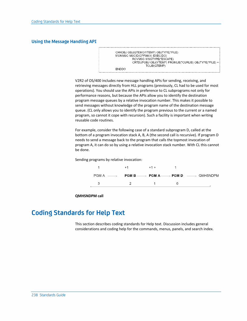
Coding Standards for Help Text
238 Standards Guide
Using the Message Handling API
V2R2 of OS/400 includes new message handling APIs for sending, receiving, and retrieving messages directly from HLL programs (previously, CL had to be used for most operations). You should use the APIs in preference to CL subprograms not only for performance reasons, but because the APIs allow you to identify the destination program message queues by a relative invocation number. This makes it possible to send messages without knowledge of the program name of the destination message queue. (CL only allows you to identify the program previous to the current or a named program, so cannot it cope with recursion). Such a facility is important when writing reusable code routines.
For example, consider the following case of a standard subprogram D, called at the bottom of a program invocation stack A, B, A (the second call is recursive). If program D needs to send a message back to the program that calls the topmost invocation of program A, it can do so by using a relative invocation stack number. With CL this cannot be done.
Sending programs by relative invocation:
QMHSNDPM call
Coding Standards for Help Text
This section describes coding standards for Help text. Discussion includes general considerations and coding help for the commands, menus, panels, and search index.

Coding Standards for Help Text
Chapter 5: Coding Standards for Database Files 239
General Considerations
When writing help text, keeping the following points in mind:
■ Comply with UIS design standards for emphasis and layout.
■ Achieve reusability. Structure your help groups and panel groups carefully, and make use of standard text fragments.
■ Minimize the work required to translate help text. Modularize your help groups and use message descriptions.
For more information, refer to the OS/400 Guide to Programming Application and Help Displays.
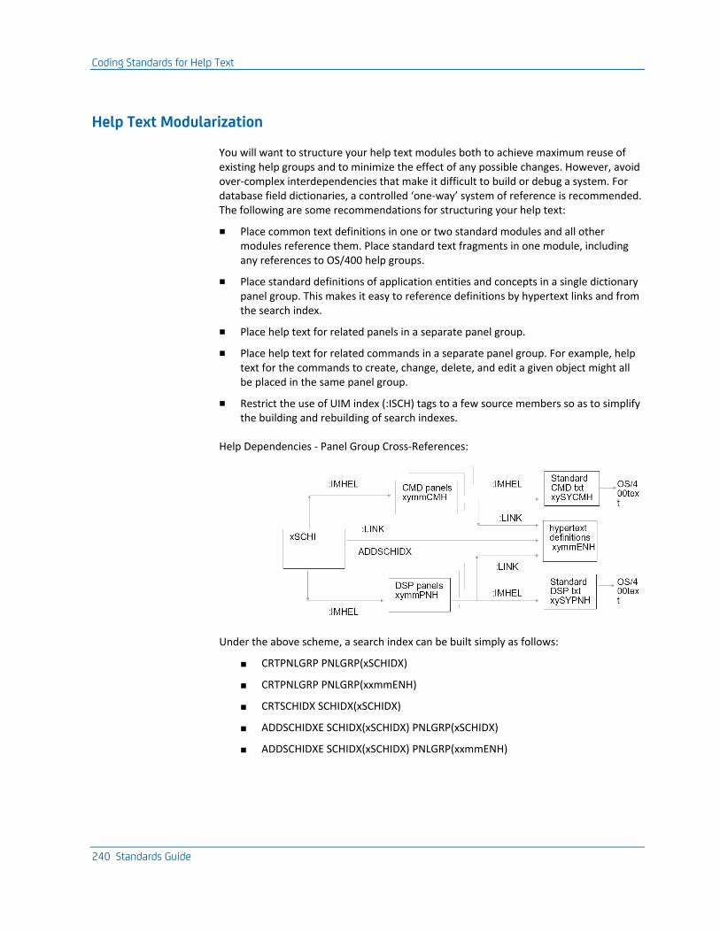
Coding Standards for Help Text
240 Standards Guide
Help Text Modularization
You will want to structure your help text modules both to achieve maximum reuse of existing help groups and to minimize the effect of any possible changes. However, avoid over-complex interdependencies that make it difficult to build or debug a system. For database field dictionaries, a controlled ‘one-way’ system of reference is recommended. The following are some recommendations for structuring your help text:
■ Place common text definitions in one or two standard modules and all other modules reference them. Place standard text fragments in one module, including any references to OS/400 help groups.
■ Place standard definitions of application entities and concepts in a single dictionary panel group. This makes it easy to reference definitions by hypertext links and from the search index.
■ Place help text for related panels in a separate panel group.
■ Place help text for related commands in a separate panel group. For example, help text for the commands to create, change, delete, and edit a given object might all be placed in the same panel group.
■ Restrict the use of UIM index (:ISCH) tags to a few source members so as to simplify the building and rebuilding of search indexes.
Help Dependencies - Panel Group Cross-References:
Under the above scheme, a search index can be built simply as follows:
■ CRTPNLGRP PNLGRP(xSCHIDX)
■ CRTPNLGRP PNLGRP(xxmmENH)
■ CRTSCHIDX SCHIDX(xSCHIDX)
■ ADDSCHIDXE SCHIDX(xSCHIDX) PNLGRP(xSCHIDX)
■ ADDSCHIDXE SCHIDX(xSCHIDX) PNLGRP(xxmmENH)
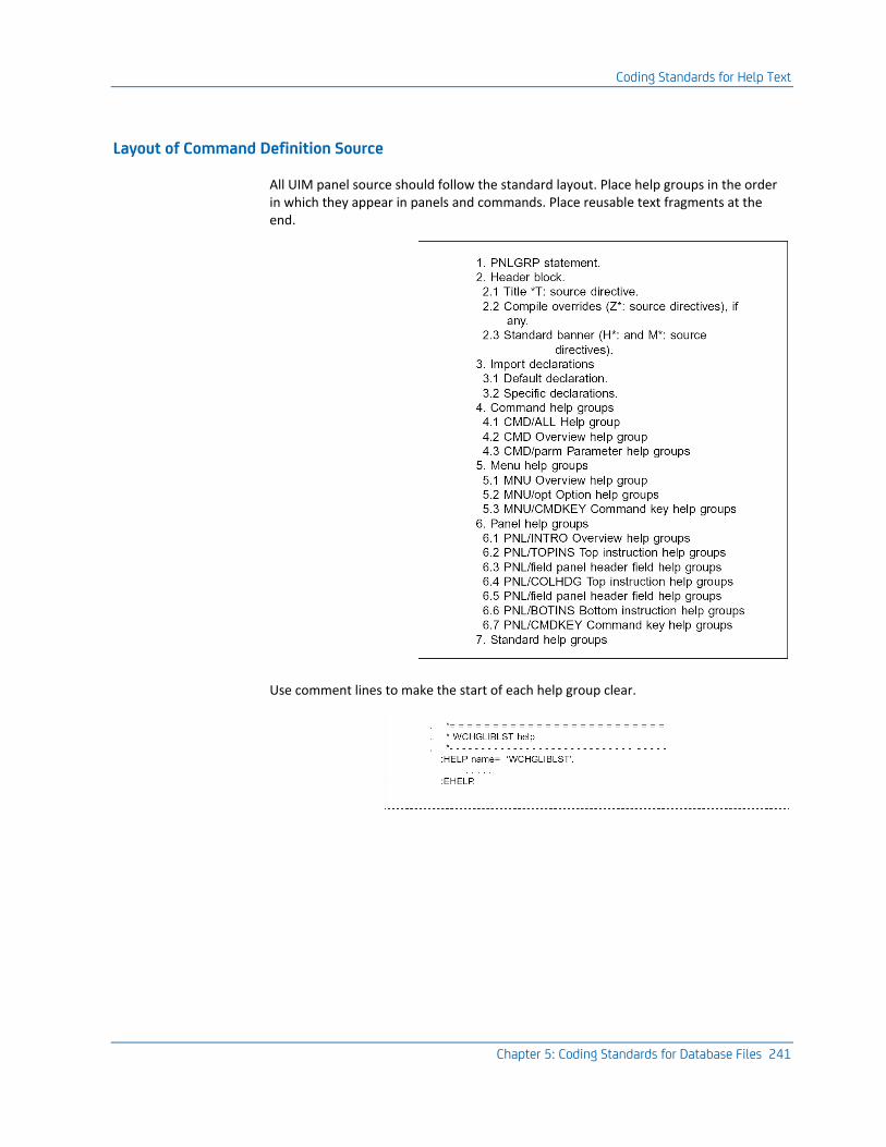
Coding Standards for Help Text
Chapter 5: Coding Standards for Database Files 241
Layout of Command Definition Source
All UIM panel source should follow the standard layout. Place help groups in the order in which they appear in panels and commands. Place reusable text fragments at the end.
Use comment lines to make the start of each help group clear.
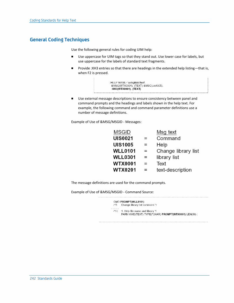
Coding Standards for Help Text
242 Standards Guide
General Coding Techniques
Use the following general rules for coding UIM help:
■ Use uppercase for UIM tags so that they stand out. Use lower case for labels, but use uppercase for the labels of standard text fragments.
■ Provide :XH3 entries so that there are headings in the extended help listing—that is, when F2 is pressed.
■ Use external message descriptions to ensure consistency between panel and command prompts and the headings and labels shown in the help text. For example, the following command and command parameter definitions use a number of message definitions.
Example of Use of &MSG/MSGID - Messages:
The message definitions are used for the command prompts.
Example of Use of &MSG/MSGID - Command Source:
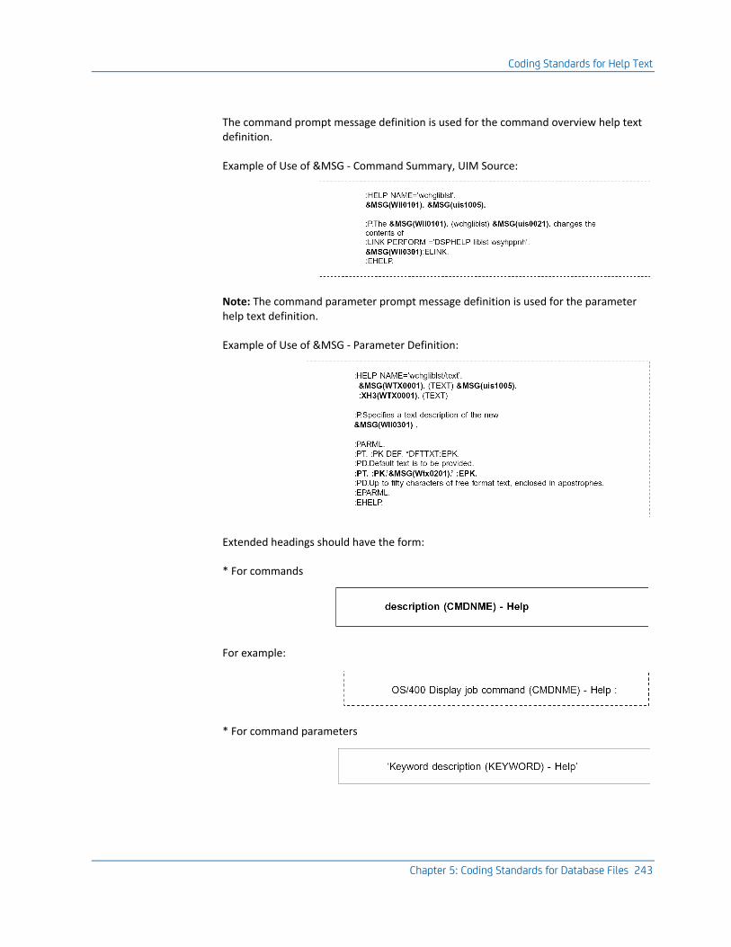
Coding Standards for Help Text
Chapter 5: Coding Standards for Database Files 243
The command prompt message definition is used for the command overview help text definition.
Example of Use of &MSG - Command Summary, UIM Source:
Note: The command parameter prompt message definition is used for the parameter help text definition.
Example of Use of &MSG - Parameter Definition:
Extended headings should have the form:
* For commands
For example:
* For command parameters
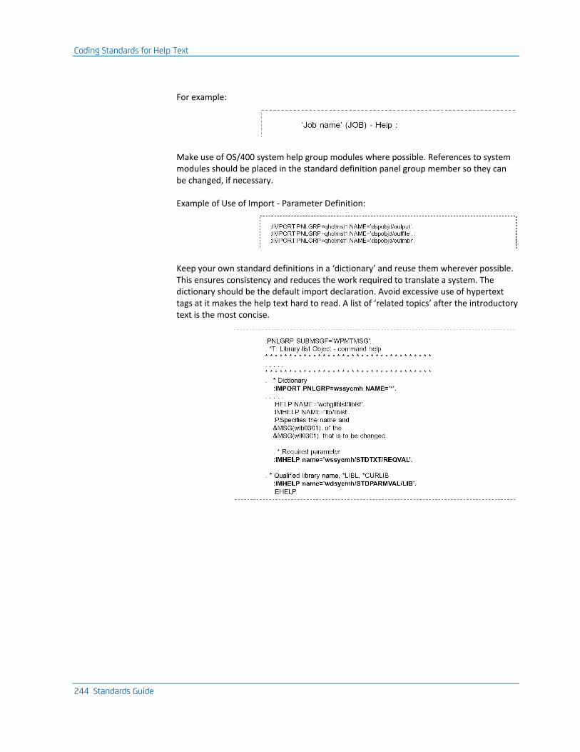
Coding Standards for Help Text
244 Standards Guide
For example:
Make use of OS/400 system help group modules where possible. References to system modules should be placed in the standard definition panel group member so they can be changed, if necessary.
Example of Use of Import - Parameter Definition:
Keep your own standard definitions in a ‘dictionary’ and reuse them wherever possible. This ensures consistency and reduces the work required to translate a system. The dictionary should be the default import declaration. Avoid excessive use of hypertext tags at it makes the help text hard to read. A list of ‘related topics’ after the introductory text is the most concise.
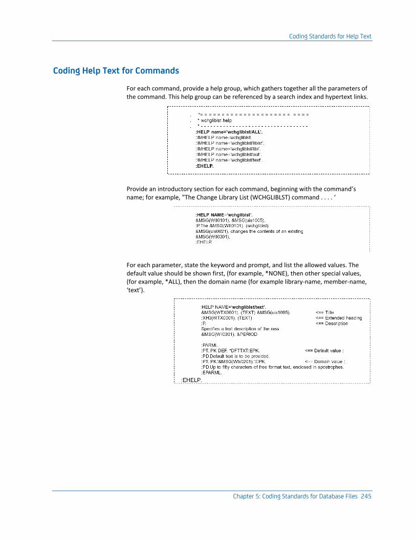
Coding Standards for Help Text
Chapter 5: Coding Standards for Database Files 245
Coding Help Text for Commands
For each command, provide a help group, which gathers together all the parameters of the command. This help group can be referenced by a search index and hypertext links.
Provide an introductory section for each command, beginning with the command’s name; for example, "The Change Library List (WCHGLIBLST) command . . . . ‘
For each parameter, state the keyword and prompt, and list the allowed values. The default value should be shown first, (for example, *NONE), then other special values, (for example, *ALL), then the domain name (for example library-name, member-name, ‘text’).
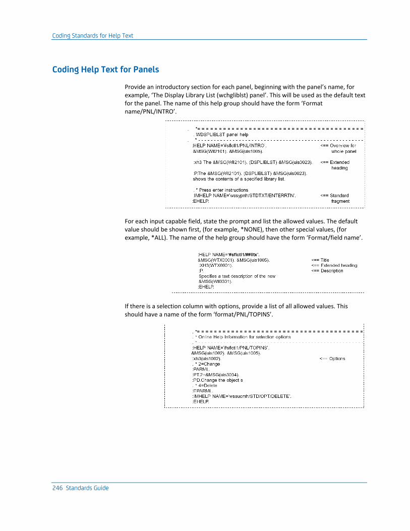
Coding Standards for Help Text
246 Standards Guide
Coding Help Text for Panels
Provide an introductory section for each panel, beginning with the panel’s name, for example, ‘The Display Library List (wchgliblst) panel’. This will be used as the default text for the panel. The name of this help group should have the form ‘Format name/PNL/INTRO’.
For each input capable field, state the prompt and list the allowed values. The default value should be shown first, (for example, *NONE), then other special values, (for example, *ALL). The name of the help group should have the form ‘Format/field name’.
If there is a selection column with options, provide a list of all allowed values. This should have a name of the form ‘format/PNL/TOPINS’.
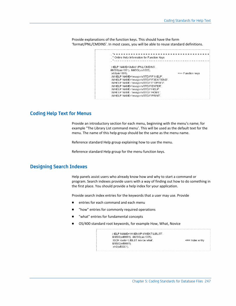
Coding Standards for Help Text
Chapter 5: Coding Standards for Database Files 247
Provide explanations of the function keys. This should have the form ‘format/PNL/CMDINS’. In most cases, you will be able to reuse standard definitions.
Coding Help Text for Menus
Provide an introductory section for each menu, beginning with the menu’s name; for example "The Library List command menu’. This will be used as the default text for the menu. The name of this help group should be the same as the menu name.
Reference standard Help group explaining how to use the menu.
Reference standard Help group for the menu function keys.
Designing Search Indexes
Help panels assist users who already know how and why to start a command or program. Search indexes provide users with a way of finding out how to do something in the first place. You should provide a help index for your application.
Provide search index entries for the keywords that a user may use. Provide
■ entries for each command and each menu
■ "how" entries for commonly required operations
■ "what" entries for fundamental concepts
■ OS/400 standard root keywords, for example How, What, Novice
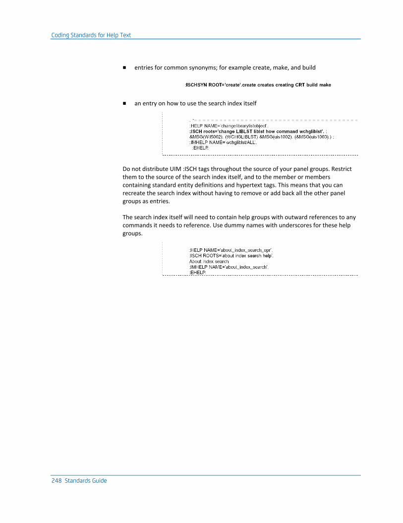
Coding Standards for Help Text
248 Standards Guide
■ entries for common synonyms; for example create, make, and build
■ an entry on how to use the search index itself
Do not distribute UIM :ISCH tags throughout the source of your panel groups. Restrict them to the source of the search index itself, and to the member or members containing standard entity definitions and hypertext tags. This means that you can recreate the search index without having to remove or add back all the other panel groups as entries.
The search index itself will need to contain help groups with outward references to any commands it needs to reference. Use dummy names with underscores for these help groups.
Chapter 6: Work Management Standards 249
Chapter 6: Work Management Standards
This chapter describes work management standards.
This section contains the following topics:
Introduction (see page 249) Shipped Work Management Objects (see page 250) Job Descriptions (see page 253) Queues (see page 253) Print File Direction (see page 254) User Profile and Security Standards (see page 255) Implementation of Security (see page 262) Using Libraries (see page 267) Version Control (see page 275) Backup and Recovery (see page 279) Backing-Up (see page 282)
Introduction
OS/400 Work Management allows you to control submitting, queuing and executing jobs, and spooling their output. Most of the aspects of jobs that you want to control, such as job priority, job queue, and output queue, are parameterized, and may be changed interactively. The CA 2E Toolkit utilities extend the flexibility of Work Management by allowing stored library lists, menus, and additional user profile parameters.
General Principles
As general principles:
■ Make use of shipped objects. They provide a good starting point.
■ Record modifications to the shipped system in programs.
■ Avoid coding Work Management parameters in programs. Doing so removes flexibility.
Shipped Work Management Objects
250 Standards Guide
Shipped Work Management Objects
OS/400 is shipped with a default set of Work Management objects (for example, QBATCH, QPRINT, QINTER). If you are a new user, use these to start and then modify them over time. The commands to make the modifications should be stored in a CL program or a spool reader so that they can be reapplied at any time. This is necessary in particular for the changes that are ‘undone’ by reinstalling new releases of the operating system; for instance, overrides to print files in QSYS.
Such a program should includes changes to OS/400 system values made with the OS/400 Change System value (CHGSYSVAL) command, although such changes are preserved when a new release of the operating system is installed. These include:
■ System date format (QDATFMT, QDATSEP), decimal symbol (QDECFMT), and currency symbol (QCURSYM)
■ System part of library list (QSYSLIBL), which should normally include QSYS, QUSRSYS, QHLPSYS
■ System user library list (QUSRLIBL), which should normally include QTEMP, QGPL, and the CA 2E Toolkit utility library
■ Tuning parameters like Base pool size (QBASPOOL) and activity level (QBASACTLVL)
■ Job accounting level (QACGLVL), if job accounting is being used
■ Default print identification text (QPRTTXT).
■ Changes to print file attributes
All files in the system library QSYS and other utility libraries should be given the default forms size for your installation. For example:
CHGPRTF FILE(QSYS/*ALL) PAGESIZE(88 132) LPI(8) +
CPI(15) OVRFLW(80) RPLUNPRT(*YES)
The files used for compilation listings should be held (set to HOLD(*YES)), so that listings can be examined online, using the browse scan facility of the OS/400 Start SEU (STRSEU) command. They should not normally need printing:
CHGPRTF FILE(QPDDSSRC) SCHEDULE(*FILEEND) HOLD(*YES)
CHGPRTF FILE(QSYSPRT) SCHEDULE(*FILEEND) HOLD(*YES)
Job logs and program dumps should be directed to a separate queue. They can then be found easily, but will not normally be printed.
For example:
CRTOUTQ OUTQ(QGPL/YQJOBLOG) DSPDTA(*YES) +

Shipped Work Management Objects
Chapter 6: Work Management Standards 251
TEXT(‘Job logs & dump output’)
CHGPRTF FILE(QSYS/QPJOBLOG) OUTQ(YQJOBLOG) HOLD(*YES)
CHGPRTF FILE(QSYS/QPPGMDMP) OUTQ(YQJOBLOG) HOLD(*YES)
CHGPRTF FILE(QSYS/QPSRVDMP) OUTQ(YQJOBLOG) HOLD(*YES)
CHGPRTF FILE(QSYS/QPDSPJOB) OUTQ(YQJOBLOG) HOLD(*YES)
Work Management Objects in QGPL
You might also wish to include in your program changes to subsystems which you have made—for instance to have auto-start entries, routing entries, and additional job queues, and changes to job descriptions, job queues, output queues and classes.
OS/400 Shipped Authorities
In particular, you might wish to revoke public rights to use certain commands, or to add objects to any of the libraries in the system library list.
Note: If you have specified that certain messages are to be logged in the system log, you should record this fact.
Naming Work Management Objects
Work management objects should generally be given meaningful names. Associated objects of different types can have the same name; for instance QBATCH for a related job description, job queue, class and subsystem, or you might create a user subsystem UBATCH, with associated job queue UBATCH, class UBATCH, and job description UBATCH.
Shipped Work Management Objects
252 Standards Guide
Preserving Work Management Flexibility
As a matter of principle, avoid hard coding the work management parameters in your own programs, as this makes it hard to alter them without reprogramming.
For instance, if you needed to produce two copies of a report in a program you could either:
■ Code an Override print file (OVRPRTF) statement with COPIES(2)
■ Change the print file attributes with the OS/400 Change Print file (CHGPRTF) command
Note: The latter solution is preferable, as it does not require a programming change to revise the number of copies produced. (It does require that there be a separate print file for the report.) Alternatively, you could make the number of copies a run time parameter when executing the report. For example, use the OS/400 Override print file (OVRPRTF) command with COPIES(&COPIES) specified.
Likewise, if you have a program that submits a job, do not hard code the job attributes (such as the job priority) on the ‘submit job’ statement. Instead, create a job description that has the desired attributes, and submit the job using the job description. The job attributes for new jobs may then be changed at any time, simply by altering the job description.
Another technique that can be used is to store a command that may need to be changed as a message on a message file, and to retrieve it at execution time for execution with the OS/400 execution program QCMDEXC. The message description can then be modified at any time using the OS/400 Change message description (CHGMSGD) command. This technique is used to implement the CA 2E EXCMSG function.
Job Descriptions
Chapter 6: Work Management Standards 253
Job Descriptions
Job descriptions provide a convenient mechanism for controlling the execution attributes of a submitted job, including the job queue to be used, and the execution priority.
Job descriptions for starting batch jobs should normally be created:
■ With a logging level of LOG(4 00 *NOLIST). This is the default on IBM i. This ensures a maximum logging level if an error occurs, but suppresses the log if the job completes normally.
■ To use an automatic reply list, for example, with INQMSGRPY(*YES). This ensures that if the job crashes, subsequent jobs in the queue are not held up. If subsequent jobs depend upon the successful completion of the first job, then the application design should take this into account, either by a check for successful completion of the preceding step, or by use of an exception message program to cancel the subsequent jobs.
Note: For job description names, the names QBATCH and QPGMR should be used where possible, and object identification controlled by library list.
Queues
Job and Print Queue Names—The default Work Management names QPRINT, QBATCH and QPGMR should be used where possible, and object identification controlled by library list. Consider introducing a different output queue for each forms type used.
Message Queues—Display device message queues (created automatically by OS/400) will be given the same name as the associated device. OS/400 will also automatically create a message queue for each user profile. Other message queue names should describe their role. For example, ‘NGHTERRMSG’ - error messages from the overnight batch run.
Message queues can be particularly useful for providing log functions. For each application system, consider introducing three message queues (xxxSYSOPR, xxxHSTLOG, and xxxCHGLOG), each with a particular role:
■ An exception message queue to contain information about errors and exceptions. This is analogous to the OS/400 QSYSOPR message queue.
■ A log message queue to contain audit information recording important processing stages; for example, end of period processing.
■ An object change log message queue. The CA 2E Toolkit Move object (YMOVOBJ) and Move object & source (YMOVOBJSRC) commands may be used to send messages automatically to this log to record object changes when objects are moved into the live system.
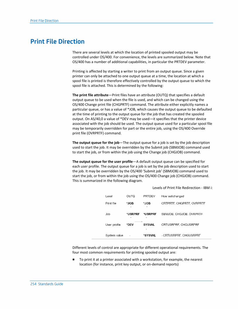
Print File Direction
254 Standards Guide
Print File Direction
There are several levels at which the location of printed spooled output may be controlled under OS/400. For convenience, the levels are summarized below. Note that OS/400 has a number of additional capabilities, in particular the PRTDEV parameter.
Printing is affected by starting a writer to print from an output queue. Since a given printer can only be attached to one output queue at a time, the location at which a spool file is printed is therefore effectively controlled by the output queue to which the spool file is attached. This is determined by the following:
The print file attribute—Print files have an attribute (OUTQ) that specifies a default output queue to be used when the file is used, and which can be changed using the OS/400 Change print file (CHGPRTF) command. The attribute either explicitly names a particular queue, or has a value of *JOB, which causes the output queue to be defaulted at the time of printing to the output queue for the job that has created the spooled output. On AS/40,0 a value of *DEV may be used—it specifies that the printer device associated with the job should be used. The output queue used for a particular spool file may be temporarily overridden for part or the entire job, using the OS/400 Override print file (OVRPRTF) command.
The output queue for the job—The output queue for a job is set by the job description used to start the job. It may be overridden by the Submit job (SBMJOB) command used to start the job, or from within the job using the Change job (CHGJOB) command.
The output queue for the user profile—A default output queue can be specified for each user profile. The output queue for a job is set by the job description used to start the job. It may be overridden by the OS/400 ‘Submit job’ (SBMJOB) command used to start the job, or from within the job using the OS/400 Change job (CHGJOB) command. This is summarized in the following diagram.
Levels of Print File Redirection - IBM i:
Different levels of control are appropriate for different operational requirements. The four most common requirements for printing spooled output are:
■ To print it at a printer associated with a workstation, for example, the nearest location (for instance, print key output, or on-demand reports)

User Profile and Security Standards
Chapter 6: Work Management Standards 255
■ To print it at a printer associated with a user, regardless of where the user is (for instance, confidential, or on-demand reports)
■ To print it always at the system printer (as in the case of large reports), or at a particular printer (as in the case of reports on special forms, or with special font requirements)
■ To not print it at all (for example job logs, compilation listings)
The recommended standard is to use the defaulting mechanisms whenever possible so that print output can be redirected generically. In particular, you should set the print file output queue of print files to OUTQ(*JOB), so that all print output for a workstation can then be redirected simply by using the CHGJOB command. OUTQ(*JOB) is particularly suitable for meeting the first and second requirements above. The third and fourth requirements above can best be achieved using the OS/400 Change print file (CHGPRTF) command.
Scheduling Print Output
If a batch job produces several different reports and you wish them all to be printed together, you should use the SCHEDULE(*JOBEND) parameter to ensure this happens.
User Profile and Security Standards
The following section discusses information relevant to user profiles and security.
User Profile and Security Standards
256 Standards Guide
User Profiles
OS/400 user profiles allow you to achieve a precise modulation of who can do what on the machine. The standards described below apply to the use of user profiles.
A user profile should be set up for each user—even if the user will have the same initial menu as other users. It is important that OS/400 user profiles are used because:
■ The authorization checking for user profiles has a microcode level implementation that is very secure. User profiles are therefore the most secure way of controlling what a user is allowed to do.
■ Individual OS/400 user profiles are a necessity for the correct use of many OS/400 functions, including authorization, audit trails, and accounting. It is important that use can be resolved down to as fine of a level as possible, for example, the individual user. In other words, a user profile not only controls what a user may do, but it is also used to trace what the user has done.
■ The use of individual user profiles permits personal addressing by electronic mail and message sending software. This is likely to be of increasing significance as your systems grow and you start to network them. For this reason, you should take care to name profiles in a systematic way.
Classes of User Profiles
The above approach requires at least one profile per user. Additional profiles can be used to aggregate users into groups, and therefore to simplify the granting of authorizations: we may classify profiles into two main classes:
Personal profiles—Each personal profile represents an individual user, either an end user or a developer. These profiles are the profiles to which individual users sign on.
Some special personal profiles representing standard roles are shipped in the system—for instance ‘QSYSOPR’ (System operator), ‘QSECOFR’ (Security officer). If the duties of a shipped profile are the responsibility of a single user, then they can be used as shipped. If more than one person carries out the duties sub-profiles should be introduced to maintain accountability.
Impersonal profiles—impersonal profiles represent groupings. Users never actually sign on to them. Group profiles are normally impersonal profiles.
Some impersonal profiles represent products rather than operational groups; for example QSYS, YSYS. These profiles are granted the necessary rights for programs to adopt to carry out the functions of the product.
User Profile and Security Standards
Chapter 6: Work Management Standards 257
Group Profiles
There are many reasons to use group profiles:
■ It is easy to give new group members the necessary authorizations. Rights required by all members of the group can be given just once to the group. New members automatically have the required rights.
■ It is easy to add or change authorizations for all the members. Alterations to the rights required by all members of the group can be made just once for the group. All members then automatically have the new rights.
■ Common resources can be shared. For example, a project team working on the same objects can all manage the objects.
■ It makes the operational associations and responsibilities clear. The OS/400 cross-referencing tools can be used to document departmental associations.
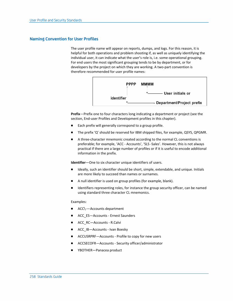
User Profile and Security Standards
258 Standards Guide
Naming Convention for User Profiles
The user profile name will appear on reports, dumps, and logs. For this reason, it is helpful for both operations and problem shooting if, as well as uniquely identifying the individual user, it can indicate what the user’s role is, i.e. some operational grouping. For end users the most significant grouping tends to be by department, or for developers by the project on which they are working. A two-part convention is therefore recommended for user profile names:
Prefix—Prefix one to four characters long indicating a department or project (see the section, End-user Profiles and Development profiles in this chapter).
■ Each prefix will generally correspond to a group profile.
■ The prefix ‘Q’ should be reserved for IBM shipped files, for example, QSYS, QPGMR.
■ A three-character mnemonic created according to the normal CL conventions is preferable; for example, ‘ACC - Accounts’, ‘SLS -Sales’. However, this is not always practical if there are a large number of profiles or if it is useful to encode additional information in the prefix.
Identifier—One to six character unique identifiers of users.
■ Ideally, such an identifier should be short, simple, extendable, and unique. Initials are more likely to succeed than names or surnames.
■ A null identifier is used on group profiles (for example, blank).
■ Identifiers representing roles, for instance the group security officer, can be named using standard three character CL mnemonics.
Examples:
■ ACC\-—Accounts department
■ ACC_ES—Accounts - Ernest Saunders
■ ACC_RC—Accounts - R.Calvi
■ ACC_IB—Accounts - Ivan Boesky
■ ACCUSRPRF—Accounts - Profile to copy for new users
■ ACCSECOFR—Accounts - Security officer/administrator
■ YBOTHER—Panacea product

User Profile and Security Standards
Chapter 6: Work Management Standards 259
User Profile Names for Networks
If you run multi-machine networks, it is helpful if you can give the same profile the same name across all machines (IBM midrange). To this end, the following considerations should be kept in mind:
■ User profile names that are to be used in networks should not be more than eight characters long.
■ Certain characters (for instance underscore ‘_’) may not be used in user profile names on some other architectures machines with which you wish to communicate.
End User Profiles
There should be a separate profile for each end user. It is good practice to set up a group profile for each department and make each end user profile belong to a group profile. General authorizations can then be granted to the group profile. The group profile may also own the application objects.
The group profile should be created with PASSWORD(*NONE) so that no one can actually sign on to it. A common prefix should be assigned to the group profile.
Individual profiles within the department should be indicated by initials or some other unique identifier.
On occasion, an end user may need to have access to another department’s applications through a separate profile. This profile should be created with a different prefix for the department, but the same identifier. For example:
■ ACC_IB Accounts - Ivan Boesky
■ STK_IB Stock control - Ivan Boesky
For each group profile, it is worth considering having two special individual profiles:
■ A ‘template’ profile that can be copied to create a new user profile. This profile should have a password of *NONE.
■ An administrator/security officer profile with rights to enroll new users within the department.

User Profile and Security Standards
260 Standards Guide
Development Profiles
Development and live objects should be owned by different profiles:
■ A group profile should be set up for each project. All objects for a system should belong to this profile while under development.
■ Each developer working on a project should have his own sub-profile.
Objects created by developer sub-profiles will be owned by the group profile. To do this, specify OWNER(*GRPPRF) on the OS/400 Create User Profile (CRTUSRPRF) command. This makes it possible for all developers on a given project to change any object belonging to the project.
Developers should not have update rights to live objects. This is so as to prevent inadvertent updates of a live object or source member. There may also be confidentiality reasons as well. To achieve this, you will need to have a separate profile to own the ‘live’ objects, described below. It will normally be appropriate for developers to have read rights to live objects and source so that they may provide support.
A CL source member, which can be run through a spool reader or program reader, should be kept, that contains the object authorizations necessary to make a system work; for instance, the file existence rights required for work files so that members can be created. Use should also be made of the CA 2E Toolkit compile preprocessor utility, to code compile time overrides in the source; for instance AUT(*ALL) where appropriate.
This practice allows:
■ Transfer between machines
■ Recreation of the system from source
User Profile and Security Standards
Chapter 6: Work Management Standards 261
Shipment or Owning Profiles
Live objects should not generally belong to either an end user profile or the development profiles, but rather, should be owned by a separate shipment profile. The profile may only be used by an administrator who is responsible for taking tested objects from the developers and implementing them into a live system. The shipment profile is not used either for development, or to run the application.
If security is a particular concern—for instance in a financial environment—then objects should be recompiled by the administrator as part of the implementation process. The CA 2E Toolkit Create Object (YCRTOBJ) command may be of use when recompiling many objects. The CA 2E Toolkit Change Object Ownership (YCHGOBJOWN) command may be of use when changing the authorizations of many objects.
It should not be necessary to be signed on as QSECOFR to install or to administer an application. If you are preparing a product for general shipment, you should ensure that the installation procedure does not require QSECOFR rights to run— many sites will not allow programs to be run under QSECOFR. You should, therefore, design an installation procedure with detailed steps.
Before installing, ensure that prior to saving and shipping, all objects are owned by the shipment profile. For example, you would enter the following command for the profile UDFTOWN.
YCHGOBJOWN OBJ(USHP/*ALL) OBJTYPE(*ALL) NEWOWN(UDFTOWN)
To install:
1. Sign on as QSECOFR.
2. Create the administrative, for example, owning profile.
CRTUSRPRF USRPRF(UDFTOWN) PASSWORD(*NONE) + TEXT(‘Widget System Owner profile’)
3. Manually grant it any essential rights, for example:
GRTOBJAUT OBJ(QSYS/CHGDTAARA) OBJTYPE(*CMD) SRPRF(UDFTOWN)
4. Sign on to a profile with restore rights and restore the objects. The objects will, therefore, be given to the shipment profile UDFTOWN.
Implementation of Security
262 Standards Guide
Security Officer Profile
You should try to use QSECOFR as little as possible. It should only be necessary to use it to administer profiles and to resolve authorization problems.
The security officer should regularly change the QSECOFR password. In order to ensure that it is always possible to obtain access to the machine as a security officer, you can use the following technique:
1. Create a special subprofile of QSECOFR, for example USECOFR.
CRTUSRPRF USRPRF(USECOFR) PASSWORD(NEVERMORE) INLPGM(QCL) + GRPPRF(QSECOFR)
Record the password to this profile in a secure place, for instance, in a safe at the bank. Do not use the profile except in emergencies.
2. In the event of an emergency, (for example, loss or unavailability of QSECOFR), the profile can be used to determine the QSECOFR profile, or to reset the password.
Implementation of Security
In a live system you will need to decide:
■ Who owns the data objects, such as database files, data areas, and data queues
■ Who owns the execution objects, such as programs, device files, and message files
■ Who may use which objects
■ Who has rights to control jobs and to examine spooled print output
Implementation of Security
Chapter 6: Work Management Standards 263
Operational Rights
The process of specifying authorizations can be extremely time consuming because of all of the many distinctions that can be made. In practice, the default rights that OS/400 gives to new objects give sensible results in most cases. It is usually sufficient to consider changing the default OS/400 operational authorization rights for only two sets of objects:
■ Commands and entry-level programs—Granting or revoking operation rights to the entry point to a function (usually a command) prevents unauthorized users from invoking a function.
■ Database files—By granting or revoking data operational rights, you can protect data, even if the entry-level protection is circumvented.
The operational rights to all other objects can be left in the public domain (the default).
A significant percentage of IBM i authority problems are caused by users not having the authorization to use certain OS/400 Create commands. The commands commonly required to create temporary work objects are:
■ Add Physical File Member (ADDPFM)
■ Create Data Area (CRTDTAARA)
■ Create Physical File (CRTPF)
■ Create Duplicate Object (CRTDUPOBJ)
Note: In the shipped system, the commands do not have public operational authorization. Consider granting public rights to the commands.
On IBM i, you can create an authorization list and attach it to each command. By adding a user profile name to the authorization list, that user profile is immediately authorized to all the commands. Alternatively, the programs that invoke the commands can borrow the rights of the program owner, rather than the user. This is achieved by specifying USRPRF(*OWNER) when creating the program.
Generic Implementation of Security
As a general principle, you should implement security at a generic level, that is, by choosing appropriate groupings of profiles and controlling rights at a library/profile level. Avoid implementing security at too detailed of a level.
Do not attempt to authorize every user explicitly to every object. Either authorize the group profile to the library containing the object, or add the group profile to an authorization list attached to the object (IBM i only).
Implementation of Security
264 Standards Guide
Management and Existence Rights
Object ownership should be retained by the project group profile. The project development sub-profiles should have management and existence rights. This can be achieved automatically if the profiles are created with the correct attributes (OWNER(*GRPPRF)).
Users do not normally require existence or management rights. Two exceptions are:
■ Text files: Users will need management rights in order to add or remove members.
■ Work files: Users will need management rights in order to add or remove work members.
Checking Authorization
Avoid explicit references to particular profile names in code, because it is then not possible to add new users without a code change.
For example, the following would be bad practice:
Instead, you should introduce an ‘authority holding’ object, such a data area, to which you may grant rights to one or many users at any time without modifying the code. You may then test the user’s authorization to the object:

Implementation of Security
Chapter 6: Work Management Standards 265
Security Exposure
Most of the likely points of security exposure are covered in the chapter on security in the IBM i (AS/400) CL Programmer’s Guide.
Standards can be adopted to protect from potential exposure on the following points:
■ Old passwords. Passwords should be changed regularly. The password change date can be used to monitor this. Use the OS/400 QPWDEXPITV command to enforce regular changing of passwords.
■ Password validation. Validate new passwords:
■ to be long enough to prevent systematic code breaking, that is, at least eight characters
■ to have non-obvious values, that is, neither user profile names or other common values; for example FRED, IBM, ME are all obvious values
■ Allowed Signons. Set the OS/400 system value that controls the number of allowed signon attempts, QMAXSIGN to a low value, for example, three.
■ Sign on levels. You should use two-level password security. On IBM i, QSECURITY should be set to 30 or 40 rather than single-level password security. This makes it impossible for users to inadvertently discover each other's passwords.
■ Workstations left signed on. Use the OS/400 QINACTITV system value to force a time out after a specified number of seconds.
■ Programs that adopt rights. A particular potential exposure is presented by programs which, although they themselves are secure, adopt owner rights created with USRPRF(*OWNER)) and call other programs. Infiltrators may attempt to replace the called objects with their own "Trojan horses" that will have the adopted rights of the calling program. Programming knowledge is needed to do this. If security is a paramount consideration, you should do the following:
■ Make sure that debug capability is removed from programs that call the OS/400 QCMDEXC program.
■ Create adopting programs with LOG(*NO) and ALWRTVSRC(*NO). This makes it harder to determine the exit points for inserting "Trojan horses". On IBM i, you can delete the observability of such programs using the OS/400 Change Program (CHGPGM) command. This makes dump analysis impossible.
■ Secure the library containing the called program by revoking object management rights to it. Also, either qualify the program call statements by including a library name for the called program, or place programs called by the adopted program in the system part of the library list and revoke object rights to the OS/400 Change System Library List (CHGSYSLIBL) command. You should probably do this in any case.
■ Restrict the adoption of rights to the minimum duration. That is, place the statements for which rights must be adopted in a small, separate subprogram.
■ Override any files that are used with SECURE(*YES).
Implementation of Security
266 Standards Guide
Note: Avoid creating programs that adopt the rights of profiles with QSECOFR rights.
■ Input and media. Make sure that you apply adequate security measures to your offline backup media (tapes and diskettes) and to printout.
■ Use of PRTTXT. Use the PRTTXT keyword to ensure that all printouts have originating text on it, for example ‘IBM RESTRICTED’.
Audit Trails
When security is particularly important, it is a good idea to design applications with an audit trail, so that all potentially sensitive actions are recorded automatically. There are some particular techniques useful for creating audit trails:
■ Use QHST. Specify that a particular message is to be copied to the log by specifying LOG(*YES) on the OS/400 Create Message Description (CRTMSGD) command. This causes a copy of the message to be placed on the QHST message queue.
■ Use a journal. Use a journal for an audit trail. Copies of sensitive requests can be written to the journal as user-defined entries. Individual journal entries cannot be deleted. You should secure the journal and its receiver:
CRTJRNRCV JRNRCV(TRAIL) PUBAUT(*NONE)
Initial Programs and Menus
The following principles should be applied when setting up user environments:
■ User systems should be menu driven, with Help text available for each interactive option.
■ Wherever possible, the CA 2E Toolkit Go to Menu (YGO) command should be used to provide menus. In this way, menus can be easily changed or updated. In addition, advanced functions can be provided in all menus, such as Help text, direct menu calling, and command request entry.
■ The CA 2E Toolkit User Access system should be used where possible to gain entry to the menu program. This requires that user profiles are created or changed with the CA 2E Toolkit Create User Profile (YCRTUSRPRF) command.
■ The CA 2E Toolkit Initial Program (YINLPGM) command should be used as the initial program for user profiles to:
■ Set the library list using a CA 2E Toolkit stored list
■ Set the message queue to break
■ Display an initial menu
For more information on the YINLPGM command, refer to the Toolkit Concepts Guide.
Using Libraries
Chapter 6: Work Management Standards 267
Using Libraries
The following principles should be applied for the use of libraries under OS/400 and the organization of a development environment on IBM i:
■ For a given application, separate the live data files, the application objects, and the source files into different libraries. The national language dependent objects, such as commands and panel groups, may also need to be separated from the other application objects.
■ For each application, use a separate set of libraries; very large libraries are inefficient to use.
■ Avoid having cross-library dependencies; for instance logical files based on physical files in different libraries, or journal receivers attached to journals in another library.
■ Keep development separate from the live systems. Separate user profiles, using object ownership and authorization to enforce this.
Note: For more information on security standards, refer to the section, User Profile and Security Standards, in this guide.
■ Make the live and the test environments as similar as possible.
■ Establish libraries to be able to determine an object’s type, and its development status (new, under test, live), by which library it is in.
■ Use software tools for the routine housekeeping tasks involved in implementing new objects.
■ Avoid explicit references to library names in code.
■ Avoid qualified references to libraries. Do not hard code references to library names as it means that the library list cannot be used to find objects.
Using Libraries
268 Standards Guide
Organizing a Development Environment
It is very important that you organize your development environment and your working methods systematically. Doing so can:
■ Significantly improve your productivity because:
■ Less time needs spent coordinating and cross-checking
■ Conflicting changes are avoided
■ Additional personnel can assist with object management and librarian functions
■ improve your product quality because:
■ Version and level errors can be reduced.
■ Component fixes can be handled efficiently.
■ Make it possible for more developers to work on the same project because the dependencies are clearer.
Development Phases
Generally, you can distinguish between two different phases of development, each with different requirements:
■ Initial development, such as feasibility studies, prototyping, early development. This tends to be both rapid and tentative. It is usually not appropriate to apply a strict version control at this stage, as it may not yet be possible to make relevant decisions such as the exact number and names of objects, and the dependencies are not apparent. Such development should be contained within development libraries. Version control and component tracking need only be introduced once the system is stable.
■ Maintenance development. Once a version of an application is in use, it is of critical importance that all modifications are carefully regulated. Full version control needs to be applied.
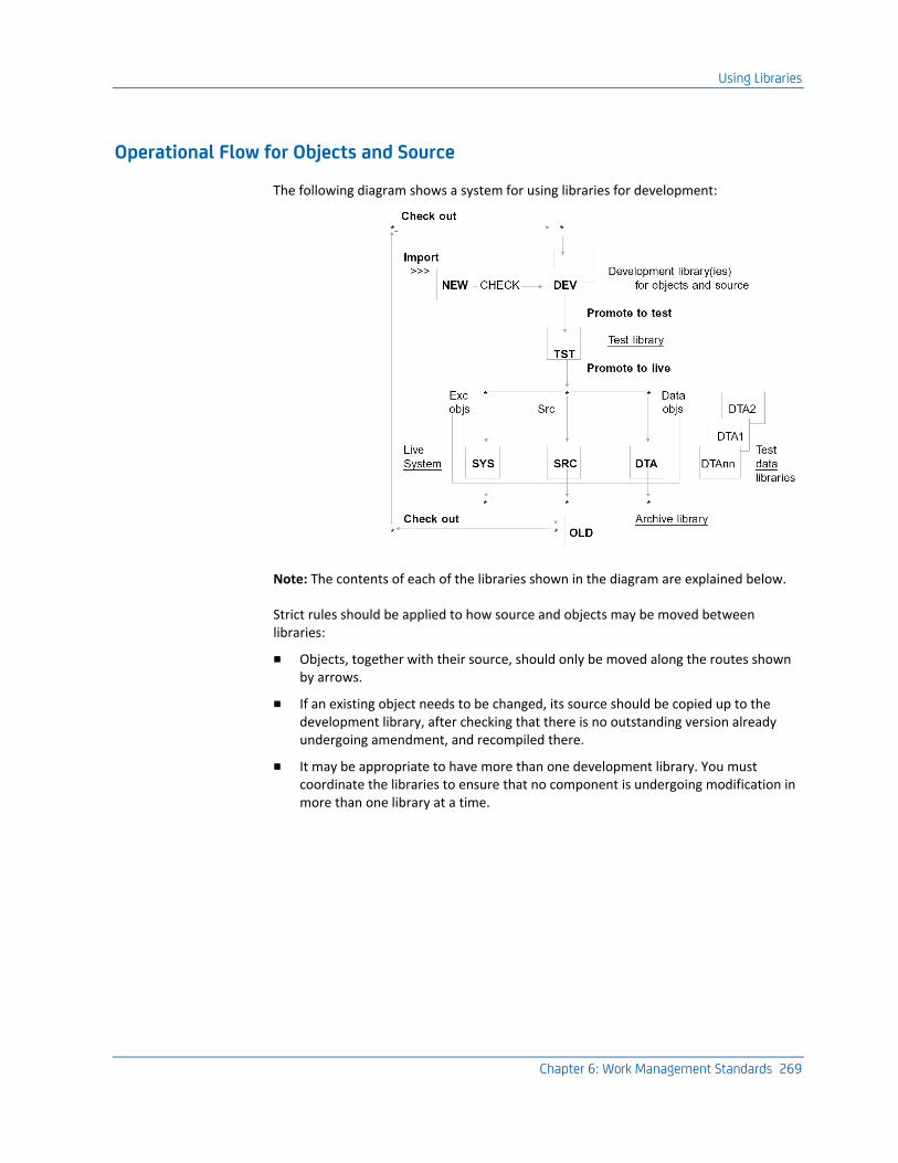
Using Libraries
Chapter 6: Work Management Standards 269
Operational Flow for Objects and Source
The following diagram shows a system for using libraries for development:
Note: The contents of each of the libraries shown in the diagram are explained below.
Strict rules should be applied to how source and objects may be moved between libraries:
■ Objects, together with their source, should only be moved along the routes shown by arrows.
■ If an existing object needs to be changed, its source should be copied up to the development library, after checking that there is no outstanding version already undergoing amendment, and recompiled there.
■ It may be appropriate to have more than one development library. You must coordinate the libraries to ensure that no component is undergoing modification in more than one library at a time.
Using Libraries
270 Standards Guide
Configuration Management
You should adopt working procedures, if necessary supported by a software tool, to follow a protocol such as the one above. Use rigorous methods to perform the following tasks:
■ Identify component dependencies. That is, decide which components must be changed along with other components.
■ Monitor component usage. That is, identify whether a component is already undergoing modification.
■ Check out components into the development environment and record that they are in use.
■ Progress components through testing.
■ Move modified components back into the live production environment.
■ Keep an audit trail of all such modifications.
CA 2E Toolkit Generic Move Utilities
The CA 2E Toolkit Move Object and Source (YMOVOBJSRC) command can be used to move objects and source from the development to the live libraries. It will also carry out functions, such as preserving authorities, archiving previous versions, separating source and objects, and creating a log of movements made.
Naming Convention for Libraries
Adopt a naming convention that distinguishes between the different library roles described above. For example:
xxxSYS Contains application objects that run the system; for example, programs, display files, print files, message files, Help text, and output queues.
xxxSYSlll Contains versions for language lll of objects needed to run the system; for example, message files, panel groups, printer files, commands, menus.
xxxDTA Contains objects containing data for a system; for example, physical files and data areas, journals, receivers and logical files. Job descriptions, with the appropriate initial library list, should also be in this library.
xxxDTAnn Test pack copies of DATA library: TYPE(*TEST).
xxxSRC Contains source for xxxEXC, xxxDTA, and objects that are needed only to create the system, not to run it.
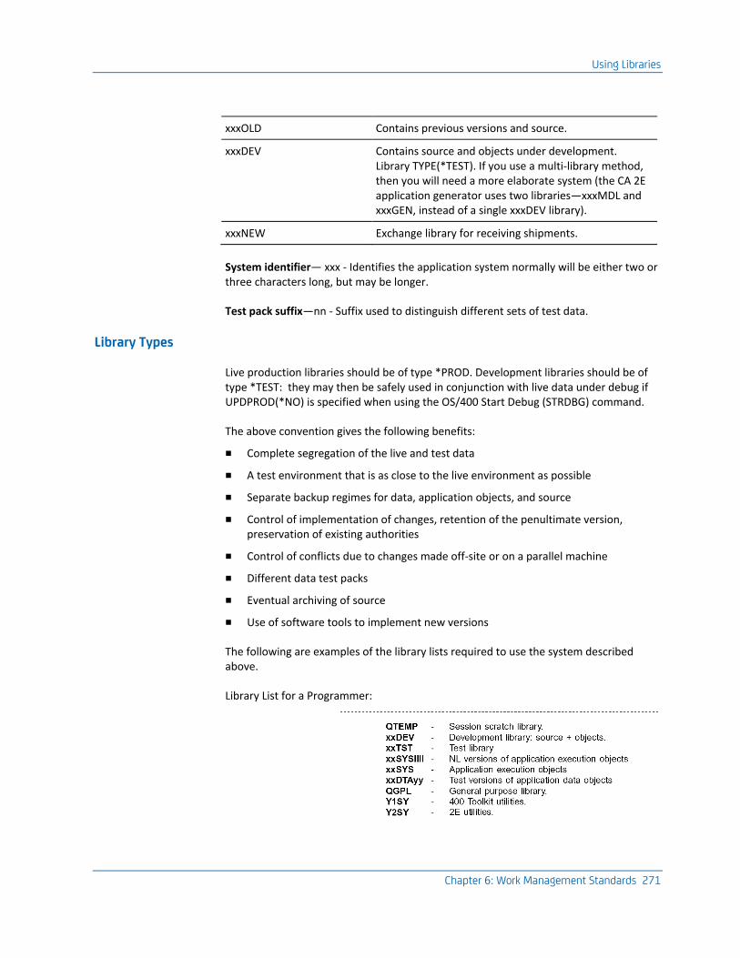
Using Libraries
Chapter 6: Work Management Standards 271
xxxOLD Contains previous versions and source.
xxxDEV Contains source and objects under development. Library TYPE(*TEST). If you use a multi-library method, then you will need a more elaborate system (the CA 2E application generator uses two libraries—xxxMDL and xxxGEN, instead of a single xxxDEV library).
xxxNEW Exchange library for receiving shipments.
System identifier— xxx - Identifies the application system normally will be either two or three characters long, but may be longer.
Test pack suffix—nn - Suffix used to distinguish different sets of test data.
Library Types
Live production libraries should be of type *PROD. Development libraries should be of type *TEST: they may then be safely used in conjunction with live data under debug if UPDPROD(*NO) is specified when using the OS/400 Start Debug (STRDBG) command.
The above convention gives the following benefits:
■ Complete segregation of the live and test data
■ A test environment that is as close to the live environment as possible
■ Separate backup regimes for data, application objects, and source
■ Control of implementation of changes, retention of the penultimate version, preservation of existing authorities
■ Control of conflicts due to changes made off-site or on a parallel machine
■ Different data test packs
■ Eventual archiving of source
■ Use of software tools to implement new versions
The following are examples of the library lists required to use the system described above.
Library List for a Programmer:
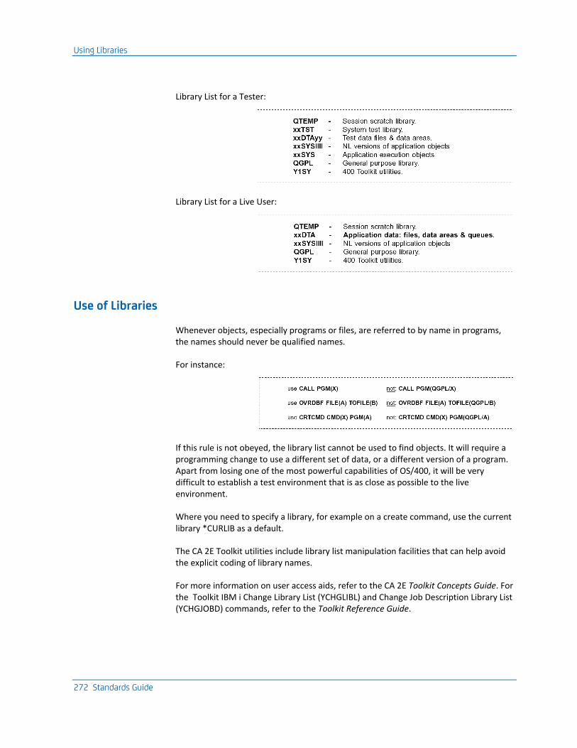
Using Libraries
272 Standards Guide
Library List for a Tester:
Library List for a Live User:
Use of Libraries
Whenever objects, especially programs or files, are referred to by name in programs, the names should never be qualified names.
For instance:
If this rule is not obeyed, the library list cannot be used to find objects. It will require a programming change to use a different set of data, or a different version of a program. Apart from losing one of the most powerful capabilities of OS/400, it will be very difficult to establish a test environment that is as close as possible to the live environment.
Where you need to specify a library, for example on a create command, use the current library *CURLIB as a default.
The CA 2E Toolkit utilities include library list manipulation facilities that can help avoid the explicit coding of library names.
For more information on user access aids, refer to the CA 2E Toolkit Concepts Guide. For the Toolkit IBM i Change Library List (YCHGLIBL) and Change Job Description Library List (YCHGJOBD) commands, refer to the Toolkit Reference Guide.
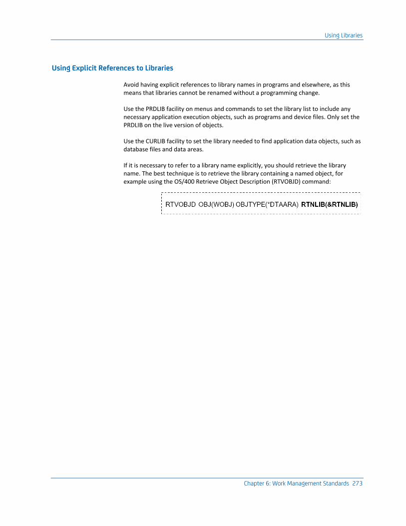
Using Libraries
Chapter 6: Work Management Standards 273
Using Explicit References to Libraries
Avoid having explicit references to library names in programs and elsewhere, as this means that libraries cannot be renamed without a programming change.
Use the PRDLIB facility on menus and commands to set the library list to include any necessary application execution objects, such as programs and device files. Only set the PRDLIB on the live version of objects.
Use the CURLIB facility to set the library needed to find application data objects, such as database files and data areas.
If it is necessary to refer to a library name explicitly, you should retrieve the library name. The best technique is to retrieve the library containing a named object, for example using the OS/400 Retrieve Object Description (RTVOBJD) command:

Using Libraries
274 Standards Guide
Using QTEMP
If a job needs to create temporary work objects in order to execute, for example, message queues, data areas, or files, the objects should be created in the job’s scratch library, QTEMP. This will ensure that:
■ The work objects will automatically be cleared up when the job terminates, even if the job crashes
■ The work objects will not conflict with the work objects of other similar jobs
Work objects should be duplicated into QTEMP by use of the OS/400 Create Duplicate Object (CRTDUPOBJ) command, working on a model object kept in the system execution object library. Note that the CRTDUPOBJ command requires that the name of the library containing the model object be specified—the name of the originating library should not be ‘hard coded’ as a literal, but retrieved, as above.
It may not be desirable to give the user rights to use the CRTDUPOBJ command, in which case a special ‘duplication program’ may be created with USER(*OWNER), which will adopt the rights of a user profile that has the necessary authorities.
You should allow for the possibility of the work object already existing in QTEMP. You do not need to delete the work object explicitly when you finish.
The following code would create a work file UUWKFLP in QTEMP from a model library, by calling a program UUCRDPC, which in turn, calls a program UULBNMR.
Version Control
Chapter 6: Work Management Standards 275
Using QGPL
The general-purpose library QGPL should be used for user-defined or modified work management objects, such as output queues, job queues, subsystems, and for other objects that may be common to all user applications on the machine. It should not contain application objects.
Version Control
Objects and source should only be moved between libraries in a strictly controlled manner, so that if there are successive changes outstanding, they are implemented serially.
Every source line has a change date on it. When copying source to the development library in order to make changes, take care not to reset the source change dates; that is, do not copy a member by adding a new member and using the SEU browse/copy function to include the old version.
A problem occurs if the programming for an application takes place on two different machines at the same time. If different changes are made to the same program on both machines concurrently, transferring either version of the program to the other machine may wipe out the other set of changes.
The problem can only be avoided completely by having a one-way flow of material, or by abstaining from changing programs on both machines at the same time. Using development libraries can help control the problem of concurrent updates as only a small number of objects need examining for potentially conflicting versions.
1. Frequent exchange of development libraries should be made to ensure that everyone is using the latest version of the source.
2. A formal ‘import’ process should be used. The development libraries should be compared before merging to ensure that concurrent changes have not been attempted. If they have, any discrepancies will need to be resolved manually. The CA 2E Toolkit lists utilities that can be of use when comparing objects and source members.
Version Control
276 Standards Guide
Object Versions
If you need to distribute new versions of the software developed on one machine around a number of ancillary sites, you should use a formal method of version control.
The main goals of a formal change control system are to:
■ Provide full upward compatibility
■ Avoid errors arising from version conflicts after an upgrade
■ Preserve existing user data in the distributed sites
■ Inform the users of any changes
The level checking mechanism of OS/400 provides some version control facilities. This will ensure that file and program levels are compatible. Level checking should always be used to provide a basic protection mechanism. For example, LVLCHK(*NO) should not be specified on OS/400 create file commands.
Upward Compatibility
A prime objective of version control is ‘upward compatibility’. New versions of applications must always support existing versions or provide a simple conversion route to the new version. Apart from the routine format level considerations, particular considerations apply to different object types:
■ Command parameters: Existing command parameter keywords and their default values should not be changed. New keywords may be added (after all existing parameters, or past the limit for positional specification as indicated by the MAXPOS keyword). New values for existing parameters may also be added.
■ Program parameters: Existing program parameter interfaces should only be changed if:
■ All references to the called program have also been changed.
■ The change is to add new parameters to the end of the parameter list and the parameter use is optional. For example:
– Escape messages. The escape messages sent by a program or command in a given set of circumstances should not be changed, nor should the message identifiers of such message be changed (unless all existing programs that call the sending program are also modified).
– Database files. If new versions of database files are provided, conversion routines for restoring existing data to the new files should be supplied.
Version Control
Chapter 6: Work Management Standards 277
Version Numbers
Version control should be based on a version numbers included in a data area or database file in the shipped software library. This number should be incremented for each functional change—note that a single change may affect a number of different objects. Therefore, documentation of any changes can be related to the fix level.
A check for prerequisite versions can be made, either manually or automatically, in order to prevent installing successive releases in the wrong order. Operating system version levels can be checked by retrieving the relevant data area for:
■ The IBM i V1R1, Q5728SS1 in library QSYS
■ The IBM i V2R1, Q5738SS1 in library QSYS
Version Installation Procedures
The installation process should be as simple and as automatic as possible. Often, it will be sufficient merely to use the OS/400 Restore Object (RSTOBJ) and Restore library (RSTLIB) commands—whether this is the case will depend upon the nature of the objects being shipped.
Execution objects, for example, items that do not contain data, such as programs, device files and message files, may generally be restored on top of the existing versions. (N.B. device files cannot be in use while this is done.)
Data objects, for example, items that contain data, such as database files and data areas, cannot generally be restored directly without losing the user’s existing data. They must, therefore, either be installed under a different name and be renamed after data conversion, or be installed to a different library and moved after data conversion.
It may also be necessary to rebuild any logical views that are based upon physical files that have been changed. In either case, a conversion program will need to be run to copy and or convert data from the existing files. It should be possible to run any data conversion procedures in one of two ways:
■ On alternative data sets in different libraries
■ On old data sets restored from diskette or tape. Conversion procedures should, if possible, be cumulative.
Note: To ensure upward compatibility, new software versions should include any necessary conversion programs.
Version Control
278 Standards Guide
OS/400 Installation Procedures
The following is the change mechanism used for IBM’s own products such as RPG III (QRPG):
1. All changed objects are given a name based on a serial number for shipment.
2. The numbered objects are restored on site with the OS/400 Load PTF (LODPTF) command, which checks that no fixes have been omitted. The LODPTF command also restores a log of changes, which includes information about dependencies.
3. The restored objects are installed by a separate command—the OS/400 Apply PTF (APYPTF) command, which renames or deletes the existing version and replaces it with the serially numbered object. This allows any required data conversion to be run at the same time.
4. Complete new releases of programs are installed by a special command—the OS/400 Load Licensed Program (LODLICPGM) command, which can run conversion programs after restoring the new objects if necessary.
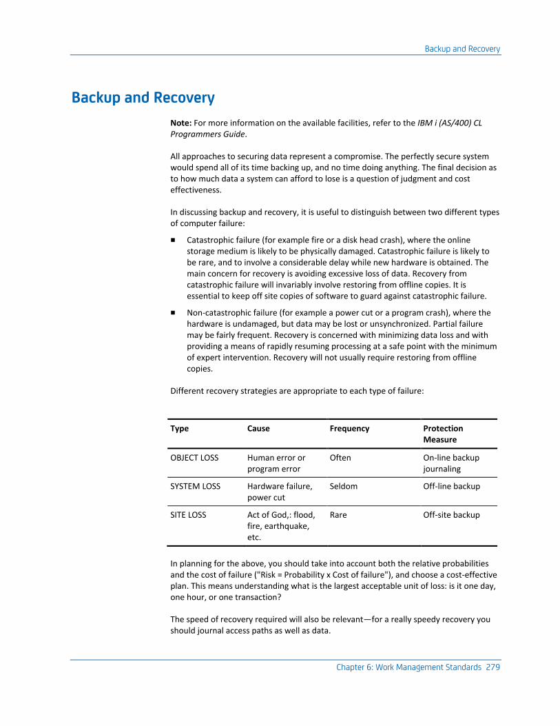
Backup and Recovery
Chapter 6: Work Management Standards 279
Backup and Recovery
Note: For more information on the available facilities, refer to the IBM i (AS/400) CL Programmers Guide.
All approaches to securing data represent a compromise. The perfectly secure system would spend all of its time backing up, and no time doing anything. The final decision as to how much data a system can afford to lose is a question of judgment and cost effectiveness.
In discussing backup and recovery, it is useful to distinguish between two different types of computer failure:
■ Catastrophic failure (for example fire or a disk head crash), where the online storage medium is likely to be physically damaged. Catastrophic failure is likely to be rare, and to involve a considerable delay while new hardware is obtained. The main concern for recovery is avoiding excessive loss of data. Recovery from catastrophic failure will invariably involve restoring from offline copies. It is essential to keep off site copies of software to guard against catastrophic failure.
■ Non-catastrophic failure (for example a power cut or a program crash), where the hardware is undamaged, but data may be lost or unsynchronized. Partial failure may be fairly frequent. Recovery is concerned with minimizing data loss and with providing a means of rapidly resuming processing at a safe point with the minimum of expert intervention. Recovery will not usually require restoring from offline copies.
Different recovery strategies are appropriate to each type of failure:
Type Cause Frequency Protection Measure
OBJECT LOSS Human error or program error
Often On-line backup journaling
SYSTEM LOSS Hardware failure, power cut
Seldom Off-line backup
SITE LOSS Act of God,: flood, fire, earthquake, etc.
Rare Off-site backup
In planning for the above, you should take into account both the relative probabilities and the cost of failure ("Risk = Probability x Cost of failure"), and choose a cost-effective plan. This means understanding what is the largest acceptable unit of loss: is it one day, one hour, or one transaction?
The speed of recovery required will also be relevant—for a really speedy recovery you should journal access paths as well as data.
Backup and Recovery
280 Standards Guide
Data Security
It is not just data loss that you need to be concerned about, but rather, the wider concept of data security. The two goals of data security are:
■ Lose as little data as possible.
■ Keep the database synchronized. Transactions requiring the update of multiple database files should function on an "all or nothing" basis.
OS/400 includes an integral system of transaction logging journaling that can help you to attain both of these targets.
Recovering from Non-Catastrophic Failure
If an interactive program crashes due to a non-catastrophic failure, it should always rollback to a safe point. The overall aim should be for an operator to be able to simply restart whichever procedure was being used at the time of failure. No explicit recovery procedures should need to be undertaken. This goal is essential to avoid having to provide continued low-level support for a system.
Automatic recovery is relatively easy to arrange for transactions that involve the update of a single database file record, as the update will have either succeeded or failed. A more difficult problem is presented when a single logical transaction requires the update of several database file records on one or more files. Briefly, there are several possible approaches:
1. Design the database update processes so that whether or not the update is deemed to occur depends on a single transaction. For example, add a status flag to a control or header record and update this last. Transactions that have an incorrect status flag are ignored.
2. For batch procedures only, the entire database could be saved before running the procedure, so that the start position can be restored in the event of a failure. Backup could be online; either to a save file or using the OS/400 Copy File (CPYF) command.
3. Use the journaling and commit control facilities of OS/400 to synchronize the transactions automatically.

Backup and Recovery
Chapter 6: Work Management Standards 281
Recovering from Catastrophic Failure
Complete recovery can be made from a catastrophic failure by restoring the last full save, plus—if journaling is being used—all journal receivers saved since the last full save. The updates contained in the journal receivers must then be reapplied using the OS/400 Apply Journal Change (APYJRNCHG) command.
If some of your applications are more essential for the continued operation of your organization than others, consider separating critical and non-critical systems into separate libraries so that the critical systems can be restored ahead of the others.
Backing-Up
282 Standards Guide
Backing-Up
How often something needs backing up depends upon how often it changes. Broadly speaking, IBM i objects can be grouped into four levels of volatility:
■ Very low volatility. QSYS (the OS/400 system library), and other shipped program product libraries such as QIDU, QRPG, QTXT, QOFC.
Most of the IBM-supplied program product libraries do not change once installed except for new releases or PTFs, and therefore, can be backed up once and for all. They should be resaved when PTFS are installed. Library QSYS does however, contain some data that may change fairly frequently, such as authority and user profile information. This should be saved at regular intervals using the OS/400 Save System (SAVSYS) command. Device configurations and modifications to system values may also change quite frequently. Since saving QSYS is a tedious process (especially when saved to diskette) and requires a dedicated machine, it is generally easier to save a record of the changes made to QSYS rather than QSYS itself. Such changes should be kept in a CL program or spool reader. Recovery then consists of restoring the last save of QSYS and rerunning the programs to modify it.
■ Low volatility. QGPL (user work management objects) and live application execution objects.
Live application execution objects (programs, device files, message files, etc.) do not change unless a modification is made to the system. Therefore, they only need backing up when a new version of the software is implemented.
■ High volatility. Live application data objects and development application execution objects.
Live application data objects (database files, data areas, data queues) probably change every day, as do the objects in development libraries. Therefore, they should be backed up regularly.
■ Very high volatility. Journal receivers.
If journaling is used, then the data in the journal receivers of live applications will probably change the whole time—from moment to moment, as data is entered and processed. In high volume or data critical applications, journals should be saved throughout the day or even be transferred continuously to a backup machine or machines.
Backing-Up
Chapter 6: Work Management Standards 283
Organizing Objects for Backup
To implement an efficient backup regime, organize your objects so that they are easy to manage from the point of view of saving and restoring. To do this:
■ Organize objects into libraries according to their volatility and functional relatedness. For example, place all volatile data objects (files and data areas) for an application together in the same library.
■ Place dependent objects in the same library. This simplifies the restore process. Place logical files in the same library as the based-on physical files. Place journal receivers in the same library as the journal to which they attach.
■ Use a naming convention for objects so that they can be identified and manipulated by type, if necessary.
Backing Up Live Application Systems
One of the goals of the library usage standards discussed is to separate objects into libraries by role. This helps to minimize the amount of backing up that has to be done.
Execution objects and source for live application systems should be kept in separate libraries that need be backed up only when a change is made to them.
The strategy adopted for backing up live application data objects, in particular, the choice of whether journaling, Save Change Objects (SAVCHGOBJ) or Save Objects/Libraries (SAVOBJ) is used, will depend on the following considerations:
■ Volume and volatility. Journaling incurs a performance overhead that may become critical on large volumes.
■ Transaction complexity. Simple transactions may not need journaling.
■ Batch/Interactive job mix. Journaling is less suitable for high volume batch applications.
Backing Up Development Systems
Because an application under development is subject to widespread change, the entire application should be saved regularly. If a catastrophic failure occurs, not more than one day’s development work should be lost. Backing development objects prevents loss of work through hardware failure and provides a measure of security against human error; for instance, the inadvertent deletion of source, objects or data.
Backing up programming changes should be done daily. This will normally involve saving the development library or libraries.
Ancillary libraries, for example, test data or development tools, may only require an occasional backup.
Backing-Up
284 Standards Guide
Backup Methods
It is worth developing a simple system to manage and support your backups.
For each backup unit (library or generic library name, object or generic object name), it should be possible to specify a save frequency (such as hourly, daily, weekly, monthly), a save method (SAVOBJ, SAVCHGOBJ, or SAVLIB), and whether the save is offline or online (save to save file).
The system should guide the operator in loading the appropriate media and should record which libraries have actually been saved on which days, and to which media.
New libraries should be added to the system automatically or semi-automatically. Renaming or deleting libraries should be ensured.
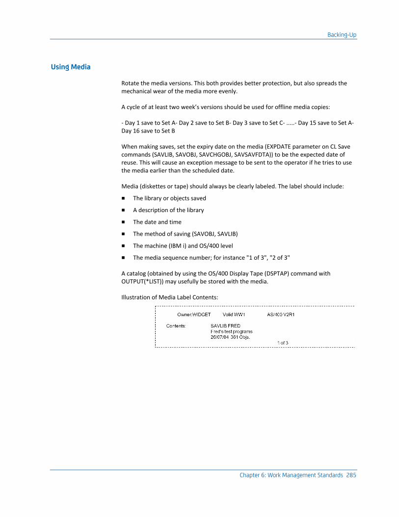
Backing-Up
Chapter 6: Work Management Standards 285
Using Media
Rotate the media versions. This both provides better protection, but also spreads the mechanical wear of the media more evenly.
A cycle of at least two week’s versions should be used for offline media copies:
- Day 1 save to Set A- Day 2 save to Set B- Day 3 save to Set C- .....- Day 15 save to Set A- Day 16 save to Set B
When making saves, set the expiry date on the media (EXPDATE parameter on CL Save commands (SAVLIB, SAVOBJ, SAVCHGOBJ, SAVSAVFDTA)) to be the expected date of reuse. This will cause an exception message to be sent to the operator if he tries to use the media earlier than the scheduled date.
Media (diskettes or tape) should always be clearly labeled. The label should include:
■ The library or objects saved
■ A description of the library
■ The date and time
■ The method of saving (SAVOBJ, SAVLIB)
■ The machine (IBM i) and OS/400 level
■ The media sequence number; for instance "1 of 3", "2 of 3"
A catalog (obtained by using the OS/400 Display Tape (DSPTAP) command with OUTPUT(*LIST)) may usefully be stored with the media.
Illustration of Media Label Contents:


Chapter 7: Standards for Testing 287
Chapter 7: Standards for Testing
This chapter describes practical guidelines for informal testing techniques. It is important to make use of software tools to organize and assist with the testing process. Some indication of possible tools is given in this chapter.
This section contains the following topics:
Types of Testing (see page 287)
Types of Testing
Implementation testing can be divided into two stages:
■ Program testing
■ System testing
In addition, there is the requirement to report and correct bugs on systems that have been implemented.
Program Testing
Program testing is done by the programmer or developer. The developer is responsible for ensuring that the tested program satisfies the following criteria:
■ Performs all the functions described in the program specification
■ Handles all non-pathological error conditions without crashing
■ Meets the coding and user interface standards
■ Is fully documented, including operating instructions
The usual unit for program testing is a single menu option—this will often correspond to a command.
Types of Testing
288 Standards Guide
Black Box and White Box Testing
Most testing methodologies distinguish between black box and white box approaches to testing.
Black box testing assumes no knowledge of the internal mechanism of a program but merely considers the inputs and outputs.
White box testing uses knowledge of a component’s internal working to focus upon critical paths. White box testing can be used to simplify the test procedures and to also ensure testing covers conditions arising from any limitations of the implementation, for example, array maxima.
Generally speaking, white box testing is most effective at a program stage; black box testing is more appropriate at a system stage.
System Testing
System testing is done by a second party, usually either the analyst or a tester. The objectives of system testing are as follows:
■ To check that programs have been properly tested
■ To check that links between different parts of the system work
■ To check that the system design works, that is, to execute all of the programs in the system, with realistic data, in a realistic order
■ To check that each program has the correct effect upon the data it handles, that is, that the database is updated correctly and that all calculations are correct
■ To test for arising conditions due to interaction between different programs, or different invocations of the same program, including record locking and deadly embraces
■ To test for arising conditions due to large volumes of data, including level breaks, page overflow, and exceeded commit maxima
Test Sheets
Progress should be monitored by means of test sheets. A test sheet is a standard form, one per program (or rather function), which will circulate between developer and tester until the program has been accepted. It includes a checklist of standard points to test, plus space for comments and errors. Preferably, this will be online.
Types of Testing
Chapter 7: Standards for Testing 289
Test Techniques
To test a whole system successfully, you will need to "divide and conquer"; that is, split the system into modules that can be tested independently. Do not try to test the whole until the parts are working.
Overall, it is important to recognize:
■ A given test will nearly always need to be repeated many times
■ A given test will be needed not only for initial development, but also later on to retest components after maintenance changes
It is therefore worthwhile, prior to testing, to spend time both formally designing test plans and preparing any tools that will assist with the process. For example:
■ Programs to set up or generate test data
■ Test harnesses and ‘scaffold’ programs to run individual programs that are normally run as part of a larger process
■ Programs to reset initial test conditions
■ Programs to document test data, for example, Queries
■ Programs to evaluate test results
PC Tools Useful for Testing
There are several PC-based testing tools. They allow you to carry out regression testing. This is the rerunning of a test case or battery of test cases after a change has been made, in order to verify that no inadvertent side effects have been introduced.
The CA 2E Toolkit utilities include a number of tools that may be useful. When testing to display or change data in database files or data areas, use the following CA 2E Toolkit commands:
■ Work with Files (YWRKF) command
■ Edit LDA (YEDTLDA) command
■ Edit GDA (YEDTGDA) command
■ Edit Data Area (YEDTDTAARA) command
To enter debug for predefined sessions, or at any point, use the following CA 2E Toolkit commands:
■ Start Debug (YSTRDBG) command
■ Set Break Program (YSETBRKPGM) command
To reset initial test conditions, use the CA 2E Toolkit Copy Files (YCPYF) command.
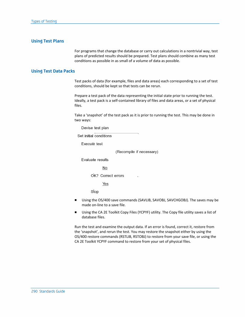
Types of Testing
290 Standards Guide
Using Test Plans
For programs that change the database or carry out calculations in a nontrivial way, test plans of predicted results should be prepared. Test plans should combine as many test conditions as possible in as small of a volume of data as possible.
Using Test Data Packs
Test packs of data (for example, files and data areas) each corresponding to a set of test conditions, should be kept so that tests can be rerun.
Prepare a test pack of the data representing the initial state prior to running the test. Ideally, a test pack is a self-contained library of files and data areas, or a set of physical files.
Take a ‘snapshot’ of the test pack as it is prior to running the test. This may be done in two ways:
■ Using the OS/400 save commands (SAVLIB, SAVOBJ, SAVCHGOBJ). The saves may be made on-line to a save file.
■ Using the CA 2E Toolkit Copy Files (YCPYF) utility. The Copy file utility saves a list of database files.
Run the test and examine the output data. If an error is found, correct it, restore from the ‘snapshot’, and rerun the test. You may restore the snapshot either by using the OS/400 restore commands (RSTLIB, RSTOBJ) to restore from your save file, or using the CA 2E Toolkit YCPYF command to restore from your set of physical files.

Types of Testing
Chapter 7: Standards for Testing 291
Manipulating Test Data
■ You should have tools for examining and altering test data.
■ You should have a means of looking at any database file that you are likely to change. The CA 2E Toolkit Work with Files (YWRKF) command can be useful in this respect.
■ The OS/400 interactive debug facility can be used to check calculation values during program execution.
■ You should have a means of listing the data from the main database files before and after each test is run.
The Test Cycle—When testing, you will be going through an iterative cycle of testing and error correction.
For each iteration, there will be an overhead involved in recompiling objects from corrected source and in resetting the test data to the initial conditions. It is, therefore, important to adopt a working method that corrects as many errors as possible during a given iteration. In other words, you should not necessarily stop at the first error you detect and attempt to correct and reiterate it, but rather, continue in order to detect and correct as many other errors as possible.
There are several techniques you can use to resume a test run, despite the occurrence of errors:
■ Use the OS/400 interactive debug facilities to correct any program variables that are preventing the completion of a test.
■ Use the CA 2E Toolkit Work with Files (YWRKF) command to correct any database fields that are preventing the completion of a test.
■ Use the CA 2E Toolkit edit data area commands (YEDTDTAARA, YEDTLDA, YEDTGDA, and YCHGDTAARA) to correct any data areas that are preventing the completion of a test.
Error Reporting—In a live system, locating the cause of a bug is often more difficult than actually fixing the bug. This is partly because the sort of bugs that elude system testing tend to be obscure, and may only occur under certain combinations of conditions, but also because they are often reported by the end user, who quite naturally may not be adept at providing the information that helps to characterize a bug. It is important, therefore, to have an error reporting procedure that helps to capture as much information about bugs as possible. The user should be trained in basic recording techniques. Automatic techniques may also be used.
For any reasonably sized system, it is desirable to have a computer-based error reporting and problem determination system:
■ To record the occurrence of an error in a standard format
■ To monitor the progress of fixes for the error
■ To allow the cross-referencing of related errors
Types of Testing
292 Standards Guide
■ As a database for a system support personnel (a ‘Helpline’ or ‘Hotline’ function)
iSeries has a number of facilities that can be used to assist with problem resolution. For example, the Question and Answer database may be used as a basis for a computerized problem reporting system.
Problem Reporting Data—Careful consideration should be given to the standard information recorded for each problem, and the classifications under which they are filed.
Some items that are generally important are:
■ Application or product name
■ Product version number and fix level
■ Operating system version number and PTF level
■ Program or object name
■ Command or menu option name
■ User name, date, and time
Include circumstantial information, such as what the user was doing at the time.
Problem Reporting Procedure—Standard practice should include the following:
■ Take a program dump if an escape message appears.
■ Preserve the job log until the problem is resolved. A print of the log may be obtained either by pressing the PRINT key while displaying the second level messages, or by taking the OS/400 Sign Off command (SIGNOFF) with LOGOFF(*LIST).
■ Print any associated displays using the PRINT key.
If you are operating on more than one machine, the Operating System version levels, including Program Temporary Fix (PTF) levels, should be recorded. The OS/400 Display Program Temporary Fix (DSPPTF) command can be used to examine the applied fixes.
Trapping Error Information Automatically—Apart from its normal job of logging facilities, OS/400 has three particular features that may be used to trap error information automatically:
■ System reply lists. A default reply to exception messages can be specified for a job using the INQMSGRPY parameter on the OS/400 Submit job (SBMJOB) or Change job (CHGJOB) commands.

Types of Testing
Chapter 7: Standards for Testing 293
■ Break message programs. An exception-handling program can be specified for particular messages using the DFTPGM parameter on the OS/400 Add Message Description (ADDMSGD) and Change Message Description (CHGMSGD) commands. Apart from dumping, the default program could carry out additional processing, such as notifying an operator. This facility can be used in conjunction with a system reply list so that the message-handling program is only invoked for certain jobs.
■ RPG III *PSSR Subroutines. Exception handling subroutines can be coded in RPG III source to achieve a similar effect to break message programs.
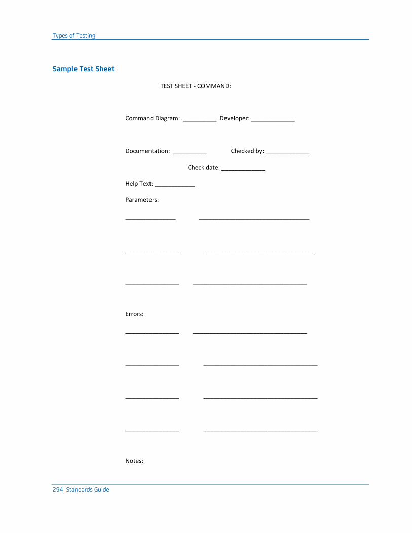
Types of Testing
294 Standards Guide
Sample Test Sheet
TEST SHEET - COMMAND:
Command Diagram: __________ Developer: _____________
Documentation: __________ Checked by: _____________
Check date: _____________
Help Text: ____________
Parameters:
_______________ _________________________________
________________ _________________________________
________________ __________________________________
Errors:
________________ __________________________________
________________ __________________________________
________________ __________________________________
________________ __________________________________
Notes:

Types of Testing
Chapter 7: Standards for Testing 295
______________________________________________________________
______________________________________________________________
______________________________________________________________
______________________________________________________________


Chapter 8: Documentation Standards 297
Chapter 8: Documentation Standards
This chapter describes the CA 2E standards for documenting application systems.
For more information on general design standards and documenting a system specification, refer to the section, General, in the chapter, "iSeries General Design Standards."
The chapter details documentation principles. It provides information on documentation that is computer generated, manually generated, and function oriented. It discusses Help text and provides standards for preparing text.
This section contains the following topics:
Considerations (see page 298)
Considerations
298 Standards Guide
Considerations ■ Prescriptive and Descriptive Documentation—It is useful to distinguish between
prescriptive and descriptive documentation.
Prescriptive documentation is needed before a system exists, in order to specify what it will be like. It may include computer-based definitions such as prototypes or data models. Prescriptive documentation includes high-level system definition documentation, such as a requirements specification or a component architecture overview.
Descriptive documentation is needed after a system exists to record what it does. There is considerable scope for producing most descriptive documentation automatically from the objects and source that comprise an application. The CA 2E Toolkit application documentation utilities mostly produce descriptive documentation, which is detailed here.
■ Documentation Principles—The following principles should be followed in preparing documentation:
■ Use design and implementation tools that provide integrated documentation facilities.
■ Use computer-based word processing and/or DTP facilities to prepare additional text documentation.
■ As far as possible, make use of the computer in collating and ordering documentation.
■ Ensure all objects and documentation have descriptive titles so as to facilitate the automatic preparation of indices and cross-references.
■ Use standards to reduce the amount of documentation. Too much documentation can be as bad as too little documentation.
■ Use computer-based tools that can create documentation from existing systems.
■ Each program should have a functional synopsis that can be extracted to provide a summary of its function. "Meaning" will still have to be provided by human intervention.
■ Provide diagrams wherever possible.
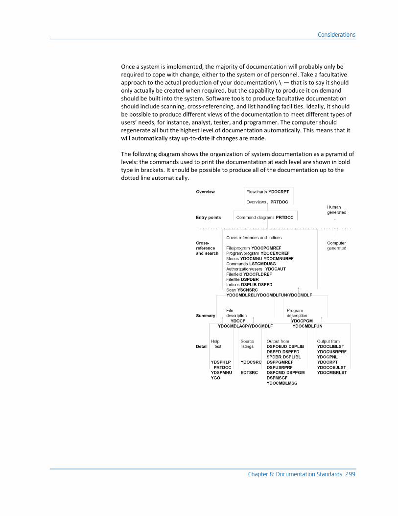
Considerations
Chapter 8: Documentation Standards 299
Once a system is implemented, the majority of documentation will probably only be required to cope with change, either to the system or of personnel. Take a facultative approach to the actual production of your documentation\-\-— that is to say it should only actually be created when required, but the capability to produce it on demand should be built into the system. Software tools to produce facultative documentation should include scanning, cross-referencing, and list handling facilities. Ideally, it should be possible to produce different views of the documentation to meet different types of users’ needs, for instance, analyst, tester, and programmer. The computer should regenerate all but the highest level of documentation automatically. This means that it will automatically stay up-to-date if changes are made.
The following diagram shows the organization of system documentation as a pyramid of levels: the commands used to print the documentation at each level are shown in bold type in brackets. It should be possible to produce all of the documentation up to the dotted line automatically.
Considerations
300 Standards Guide
■ Computer-Generated Documentation—The following documentation can be generated for all application systems, using the CA 2E Toolkit documentation utilities:
■ File layouts: The CA 2E Toolkit Document File (YDOCF) command will generate file documentation from compiled files, and will include information about fields, access paths, and dependent files.
■ Menus: The CA 2E Toolkit Document Menu (YDOCMNU) command will generate documentation for CA 2E Toolkit menus.
■ Program summaries: The CA 2E Toolkit Document Program (YDOCPGM) utility will generate program documentation, including information about parameters, required objects, and subprograms called. In order for the utility to generate full documentation, ‘H*’ source directive lines must be used in the source as comments.
■ Source listings: The CA 2E Toolkit Document Source (YDOCSRC) utility will provide compact source listings.
■ Search listings: The CA 2E Toolkit Scan Source (YSCNSRC) utility will provide listings of occurrences of given search strings in source.
■ Cross-references: A variety of cross-references can be created using CA 2E Toolkit commands; for example, program/file, menu/program.
■ Manually Generated Documentation—The following documentation should be prepared for all application systems:
■ Program Synopses: The comment section at the beginning of the source of every program should contain a statement of the purpose of the program and a summary of the functions carried out by the program.
■ Command diagrams: A standard command diagram should be provided for each command. Use a word processor to enter and to print command diagrams.
■ Message text: Message text, including second level text, should be prepared using the OS/400 Add Message Description (ADDMSGD) and Change Message Description (CHGMSGD) commands.
■ Help text: Operator instructions should be prepared for each interactive program. Use UIM help to provide help text. CA 2E will generate Help text automatically.
■ Summary flowcharts: Flowcharts and other diagram types indicating the main flow of information through the system should be prepared. The CA 2E Toolkit Work with Report (YWRKRPT) can be used to create simple diagrams up to 198 characters wide.
■ Technical overviews: Overviews should be written to describe the techniques used in the system, and to explain any special subjects; for example, backup, recovery, and end-of-period procedures.
Considerations
Chapter 8: Documentation Standards 301
■ Command Based Documentation—A number of reasons were given earlier in this manual for arranging system design around user-defined CL commands, each command being the entry point to an application function. Not least among the reasons given was that CL commands provide a natural framework for arranging the operational documentation for the application, as well as a notation for doing so. The framework has a flat structure that enables the user to look up the operational details for invoking any task directly without having to locate it through a menu hierarchy.
Documenting Commands
If commands are used to document a system, they should be documented in two separate ways:
1. With command diagrams for all commands, arranged in alphabetical order of command name. Each diagram should contain the following sections:
■ Function: A synopsis of the purpose of the command.
■ Diagram: A command diagram prepared according to the OS/400 conventions.
■ Parameters: A description of each parameter specifying the allowed values, including any defaults and special values.
■ Notes: Notes about any special considerations for using the command, and information about any prerequisite or subsequent processing steps.
■ Example: An instance of using the command.
2. With a Concepts Guide that discusses each area of the application system and names the individual commands that are relevant to that area. The concepts section provides an alternative access path for understanding the purpose of individual commands in terms of the whole application system.
For more information on an example of documenting commands, refer to the appendix, "Programming and Coding Examples," in this guide.
For good models, refer to the OS/400 CL Reference Guide (command diagrams) and the OS/400 Programmer’s Guide (concepts).
Considerations
302 Standards Guide
Messages
OS/400 messages provide a highly flexible way of providing context-sensitive documentation. Messages should be regarded as an integral part of the application system documentation.
The first level text of diagnostic messages should state what the problem is. The second level text should contain an explanation of the cause of the problem and possible solutions.
For more information on message layout conventions, refer to the section Coding Standards for Messages in the chapter "Coding Standards for Database Files" chapter in this guide.
The CA 2E Document Model Messages (YDOCMDLMSG) command provides a means of producing a message manual for your application.
Standards For Preparing Text Documentation
Preparing Text
Use word processing and/or desktop publishing tools to write the additional text needed to support an application. Ideally, you should have capabilities to do the following:
■ Integrate manually written text with computer generated documentation in composite documents.
■ Capture screen prints and report listings as text illustrations.
■ Integrate documentation version control with program version control.
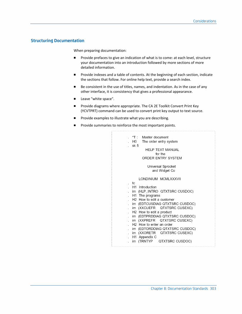
Considerations
Chapter 8: Documentation Standards 303
Structuring Documentation
When preparing documentation:
■ Provide prefaces to give an indication of what is to come: at each level, structure your documentation into an introduction followed by more sections of more detailed information.
■ Provide indexes and a table of contents. At the beginning of each section, indicate the sections that follow. For online help text, provide a search index.
■ Be consistent in the use of titles, names, and indentation. As in the case of any other interface, it is consistency that gives a professional appearance.
■ Leave "white space".
■ Provide diagrams where appropriate. The CA 2E Toolkit Convert Print Key (YCVTPRT) command can be used to convert print key output to text source.
■ Provide examples to illustrate what you are describing.
■ Provide summaries to reinforce the most important points.
Considerations
304 Standards Guide
Using Sub-documents
Break large documents into a number of smaller documents and create a master document to control their printing. This gives you greater flexibility as follows:
■ It is quicker to load, edit, and replace a small document.
■ The same sub-documents may be assembled in a number of different ways for different purposes.
■ It is easier to find text within a small document.
The following points should be observed when writing specifications, program descriptions, and operator instructions.
■ Split a complicated series of instructions into a series of numbered ‘cookbook’ steps. For example:
Not: "Adding a new client and his address is a multi-step process in which first the client is added using the new client display (unless the client was already a supplier, in which case you use the conversion display); and then add the address using the address display, although in the latter case the final step is not necessary."
But rather: "To add a new client:
1. Decide if the client is already a supplier.
2. If the client is not already a supplier:
– Add the client using the new client display.
– Add the client’s address using the address display.
3. If the client is already a supplier:
– Add the client using the conversion display."
■ Use an active voice. For example:
Not: "To display messages, the user should press F6."
But rather: "Press F6 to display your messages."
■ Write in terms of what the user is trying to achieve. For example:
Not: "This program performs a database add via a validator subprogram to the customer header and detail files."
But rather: "This program lets you add new customers to the system".
■ Work forwards in time. A simple narrative is usually more straightforward. For example:
Not: "Before you can do this, you must first add a record, before you add a record you must yourself be enrolled as a user, before which you must decide who has enrollment rights."
But rather: "To be able to do this you must first decide who has enrollment rights, secondly get him to enroll you, and thirdly, add a record."
Considerations
Chapter 8: Documentation Standards 305
■ Avoid jargon. It is legitimate to use a small vocabulary of specialist terms that a computer user may reasonably be expected to know, such as workstation, cursor, and command key, but any other terms should be explained.
Not: "The workstation terminal Help command function key provides WYSIWYG context-sensitive Help text by making a call command request to invoke the interactive on-line Help facility, which has self-extending scroll-through sub file and vectored entry. The Help display program is invoked as an interrupt using a put-override technique so that existing modified input field values are not overlaid by a subsequent put/get."
But rather: "When you press the HELP key the instructions for the current panel will be displayed. If there is more than one page of instructions, they may be displayed by pressing the ROLL key. Any data that you have already entered will still be there when you return from the Help Text display.
■ Place new terms in italics when they are introduced so as to emphasize that they are jargon words: The sub file, a special type of repeating data structure that can be used on displays, is a jolly clever idea."
Where specialist terms are introduced, use the same term consistently. Elegant variation is not required in computer manuals.
■ Be as specific as possible; use concrete terms rather than abstract ones. For example:
Not: "Various utilities may be used to manipulate text".
But rather: "Both the Edit source and the Edit text command may be used to create or change Help text".
■ Avoid compound phrases; they tend to be very ambiguous. For example:
Not: "RECORD ERROR"
But rather: Either, "A error has occurred on processing a record", or "Please log the occurrence of an error in the appropriate place".
■ Do not repeat what is already apparent from the context, nor that which could be more efficiently described centrally (such as instructions on how to use a workstation, how to display second level message text).
■ Provide examples and instances to illustrate the points you make. Counter-instances may also be useful. For example:
Not:
But rather: For example: - "* Not: ........."
■ Provide frequent sub-headings and captions to break up the text. Captions enable readers to "hone in" on the information that they are looking for —and to skip that which they are not.
■ Ask yourself, ‘What are the questions which would be crossing the mind of someone reading this?’
Considerations
306 Standards Guide
Terminology
It is important that a consistent terminology be used throughout a system. For instance, decide whether you have screens, panels, displays, or videos, workstations, VDUs, or terminals. The terminology laid down in IBM’s SAA should be used whenever possible.
Presentation Conventions
The appearance of documentation is greatly improved if consistent standards are used for punctuation, emphasis, and examples. The CA 2E internal standards are to use the following presentation conventions.
Control Language Commands in Text
Give references to commands, both OS/400 and user-defined, in the following format:
YDSPMNU MENU(FRED) FILE(FREDMENU) +
ALWCMDENT(*NO)
For example:
When quoting examples of CL code in text, always specify the parameter keywords in full, indicate a continuation with a ‘+’ sign, and use bold type for the entire command, For example, LVCHK(*NO), MAXMBRS(*NOMAX), SFLEND, MSGID.
References to parameter keywords should be in upper case and bold type; for example, LVLCHK(*NO), MAXMBRS(*NOMAX), SFLEND, and MSGID.
Use uppercase when referring to the name of an OS/400 object, whether shipped or user-defined; for instance QGPL, QTXT, QPRINT, QBATCH, YINLPGM, YDSPHLP.
Considerations
Chapter 8: Documentation Standards 307
System Entities in Text
■ Refer to iSeries and OS/400 in upper case with a slash.
■ Give references to CA 2E relations in initial capital letters in bold type.
■ Give references to CA 2E object attributes in uppercase, for example DTE, STS, and RTV.
■ Give references to entities in initial capital letters, for example, Horse.
Displays and command keys in text
■ On iSeries, give references to displays in lower case and quotes, to be consistent with the display title on the panel.
■ References to command keys should be in upper case and bold type, for example, HELP, ROLLUP, ENTER, F3.
■ In text, spell out numbers under ten; for instance, nine turtle doves not 9 turtledoves; 13 characters not thirteen characters.
Note that special conventions apply to the following diagram types:
■ Command diagrams
■ Chapter facing pages
■ CA 2E relation syntax diagrams
■ CA 2E relation examples
Headings should not have a period as punctuation.
Considerations
308 Standards Guide
Punctuation
■ The abbreviations e.g. and i.e. should be avoided. If you do use them for parenthetical information, use periods between the letters. Do not write them as ie and eg. Terms such as for example and that is are preferred.
■ When the word not is being used as a contrast, use boldface type. For instance:
Not: not like this.
But rather: not like this.
■ Use a colon to indicate the start of a list of items.
■ When a list consists of partial sentences or points, each on a different line, do not begin with a capital letter or end with a full stop, for instance:
— command diagrams
— chapter facing pages
— CA 2E relation syntax diagrams
Where points are numbered, enter numbering as 1. and 2. with the numbers followed by a period. This applies to sub-points as well, which should be designated by letters a., b., and c. Avoid roman numerals, as they do not align properly.
Chapter 9: Naming Convention Examples 309
Chapter 9: Naming Convention Examples
This appendix contains examples intended to illustrate the standard naming convention.
This section contains the following topics:
Examples (see page 309)
Examples
System letter:
■ O: Omega workshops stock control system
■ Y: CA 2E
Functional letter:
■ M: Menu
■ O: Order entry subsystem
Mnemonic:
■ MB: member
■ DS: display
■ MN: menu
■ SF: subfile
■ CD: code
Examples
310 Standards Guide
Objects:
■ YMMNDAP: Physical file
■ YMMNDAL1: Logical file view 1 on YMMNDAP
■ <%-2>YMMNDAL2: Logical file view 2 on YMMNDAP
■ YYCONMA: Data area
■ YMDSMNC: Main CL program for function M
■ YMDSMNC#: Display file used by YMDSMNC
■ YMDSMNC1: Subsidiary CL program called by YMDSMNC
■ YMDSMNC2: Subsidiary CL program called by YMDSMNC
■ YMDSMNR: RPG program
■ YMDSMNR#: Display file used by YMDSMNR
■ YDSPMNU: Command
■ YMDSMNC@: Command processing program for YDSPMNU
■ YMDSMNC#: Validity checker for YDSPMNU command
■ YMMNCMH: Panel group used by menu commands
■ YMMNPNH: Panel group used by menu panels
■ YMMNENP: Menu hypertext help groups
■ YYSYCMP: Standard command help groups
■ YYSYPNP: Standard panel help groups
■ YSCHIDX: Search index
■ YMSGF: User message file
■ YMENU: Menu task menu
■ YCMDMNU: Menu of menu commands
■ YDSPCMD: Menu of display commands
■ YYFDRFP: Field reference file
Examples
Chapter 9: Naming Convention Examples 311
Formats:
■ @@MNDAYQ: DBF format for YMMNDAP
■ #MNCD##: Panel format for an RPG program
■ #MNDA##: Panel format for an RPG program
■ #SFRC#1: Subfile record identifier
■ #SFRC#2: Subfile record identifier
■ #SFCT#1: Subfile Control record for #SFRC#1
■ #SFCT#2: Subfile Control record for #SFRC#2
■ $HDNG: Print file Heading record
■ $MNDA: Print file Detail line
Fields:
■ &SRCFILE: CLP Variable name used in a command
■ &##MNCD: CLP Variable name from a display File
■ YQMNCD: Field from dbf format @MNDAYQ
■ ##MNCD: Field from dspf format #MNCD##
■ WWMNCD: RPG work field based on YQMNCD
■ $$MNCD: RPG Entry Parameter Field
■ @@NM: RPG ARRAY name
■ NM: RPG Array index
■ W1: RPG alphabetic Work field 1 chars
■ KMNDA1: KLIST KEY for format YMNDAL1
Help panel groups:
■ YDSPMNU/ALL: YDSPMNU Command group
■ YDSPMNU: YDSPMNU Command overview
■ YDSPMNU/MENU: YDSPMNU Command parameter
■ ZSFCTZ1/PNL/INTRO: #SFCT#1 overview
■ ZSFCTZ1/PNL/TOPINS: #SFCT#1 top instruction
■ ZSFCTZ1/ZZMNCD: #SFCT#1/##MNCD field text
ZSFCTZ1/PNL/CMDINS: #SFCT#1 command keys

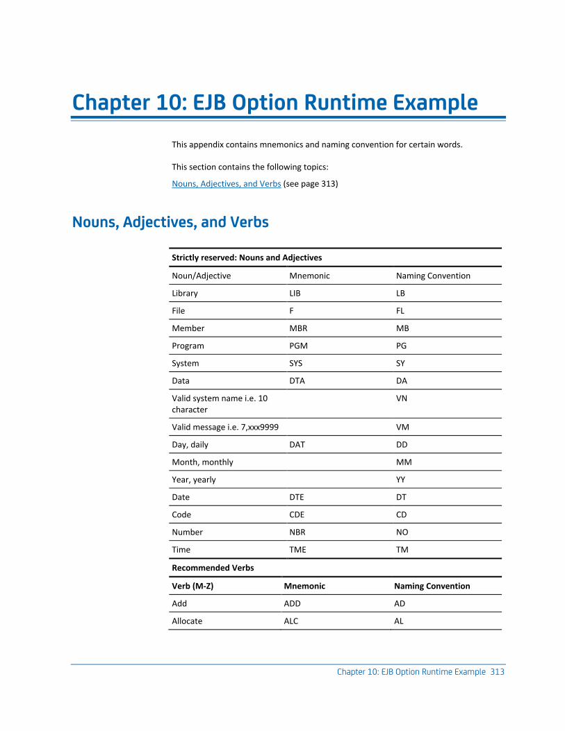
Chapter 10: EJB Option Runtime Example 313
Chapter 10: EJB Option Runtime Example
This appendix contains mnemonics and naming convention for certain words.
This section contains the following topics:
Nouns, Adjectives, and Verbs (see page 313)
Nouns, Adjectives, and Verbs
Strictly reserved: Nouns and Adjectives
Noun/Adjective Mnemonic Naming Convention
Library LIB LB
File F FL
Member MBR MB
Program PGM PG
System SYS SY
Data DTA DA
Valid system name i.e. 10 character
VN
Valid message i.e. 7,xxx9999 VM
Day, daily DAT DD
Month, monthly MM
Year, yearly YY
Date DTE DT
Code CDE CD
Number NBR NO
Time TME TM
Recommended Verbs
Verb (M-Z) Mnemonic Naming Convention
Add ADD AD
Allocate ALC AL
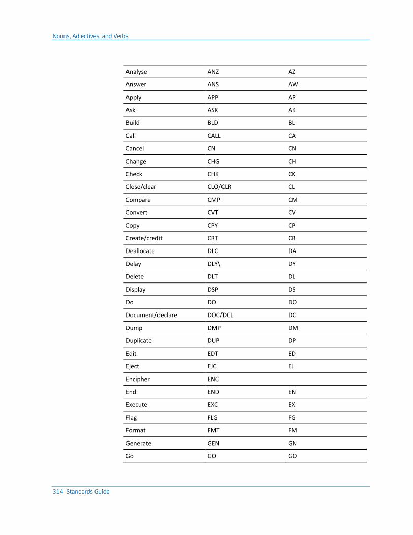
Nouns, Adjectives, and Verbs
314 Standards Guide
Analyse ANZ AZ
Answer ANS AW
Apply APP AP
Ask ASK AK
Build BLD BL
Call CALL CA
Cancel CN CN
Change CHG CH
Check CHK CK
Close/clear CLO/CLR CL
Compare CMP CM
Convert CVT CV
Copy CPY CP
Create/credit CRT CR
Deallocate DLC DA
Delay DLY\ DY
Delete DLT DL
Display DSP DS
Do DO DO
Document/declare DOC/DCL DC
Dump DMP DM
Duplicate DUP DP
Edit EDT ED
Eject EJC EJ
Encipher ENC
End END EN
Execute EXC EX
Flag FLG FG
Format FMT FM
Generate GEN GN
Go GO GO
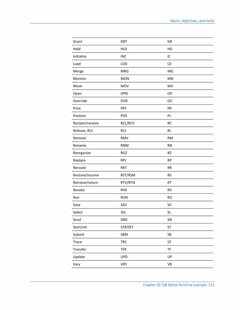
Nouns, Adjectives, and Verbs
Chapter 10: EJB Option Runtime Example 315
Grant GRT GR
Hold HLD HD
Initialize INZ IZ
Load LOD LD
Merge MRG MG
Monitor MON MN
Move MOV MV
Open OPN OP
Override OVR OV
Print PRT PR
Position POS Ps
Reclaim/receive RCL/RCV RC
Release, RLS RLS RL
Remove RMV RM
Rename RNM RN
Reorganize RGZ RZ
Replace RPL RP
Reroute RRT RR
Restore/resume RST/RSM RS
Retrieve/return RTV/RTN RT
Revoke RVK RV
Run RUN RU
Save SAV SV
Select SEL SL
Send SND SN
Start/set STR/SET ST
Submit SBM SB
Trace TRC ST
Transfer TFR TF
Update UPD UP
Vary VRY VR
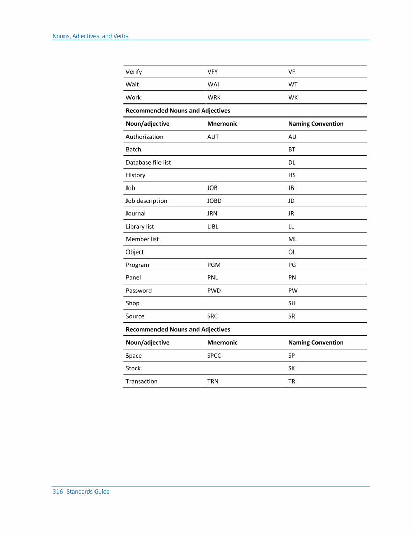
Nouns, Adjectives, and Verbs
316 Standards Guide
Verify VFY VF
Wait WAI WT
Work WRK WK
Recommended Nouns and Adjectives
Noun/adjective Mnemonic Naming Convention
Authorization AUT AU
Batch BT
Database file list DL
History HS
Job JOB JB
Job description JOBD JD
Journal JRN JR
Library list LIBL LL
Member list ML
Object OL
Program PGM PG
Panel PNL PN
Password PWD PW
Shop SH
Source SRC SR
Recommended Nouns and Adjectives
Noun/adjective Mnemonic Naming Convention
Space SPCC SP
Stock SK
Transaction TRN TR
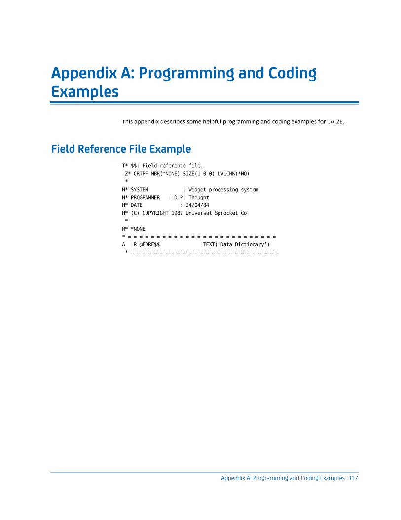
Appendix A: Programming and Coding Examples 317
Appendix A: Programming and Coding Examples
This appendix describes some helpful programming and coding examples for CA 2E.
Field Reference File Example
T* $$: Field reference file.
Z* CRTPF MBR(*NONE) SIZE(1 0 0) LVLCHK(*NO)
*
H* SYSTEM : Widget processing system
H* PROGRAMMER : D.P. Thought
H* DATE : 24/04/84
H* (C) COPYRIGHT 1987 Universal Sprocket Co
*
M* *NONE
* = = = = = = = = = = = = = = = = = = = = = = = = = =
A R @FDRF$$ TEXT(‘Data Dictionary’)
* = = = = = = = = = = = = = = = = = = = = = = = = = =
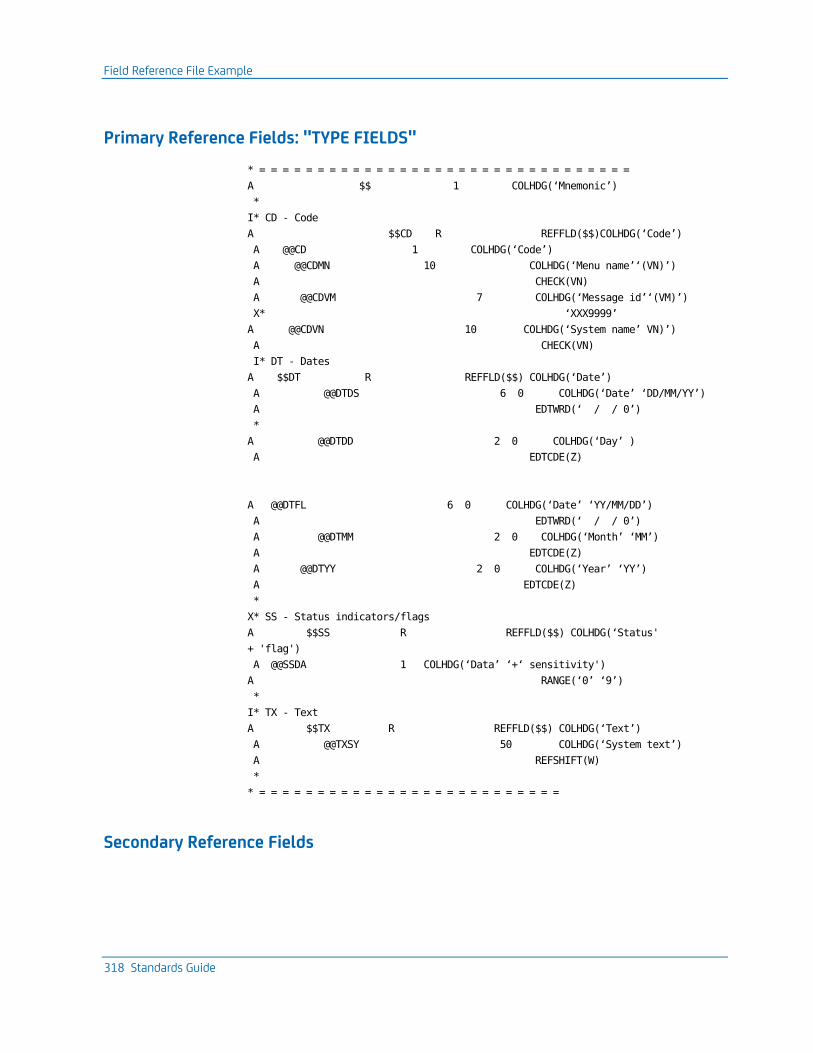
Field Reference File Example
318 Standards Guide
Primary Reference Fields: "TYPE FIELDS"
* = = = = = = = = = = = = = = = = = = = = = = = = = = = = = = = =
A $$ 1 COLHDG(‘Mnemonic’)
*
I* CD - Code
A $$CD R REFFLD($$)COLHDG(‘Code’)
A @@CD 1 COLHDG(‘Code’)
A @@CDMN 10 COLHDG(‘Menu name’‘(VN)’)
A CHECK(VN)
A @@CDVM 7 COLHDG(‘Message id’‘(VM)’)
X* ‘XXX9999’
A @@CDVN 10 COLHDG(‘System name’ VN)’)
A CHECK(VN)
I* DT - Dates
A $$DT R REFFLD($$) COLHDG(‘Date’)
A @@DTDS 6 0 COLHDG(‘Date’ ‘DD/MM/YY’)
A EDTWRD(‘ / / 0’)
*
A @@DTDD 2 0 COLHDG(‘Day’ )
A EDTCDE(Z)
A @@DTFL 6 0 COLHDG(‘Date’ ‘YY/MM/DD’)
A EDTWRD(‘ / / 0’)
A @@DTMM 2 0 COLHDG(‘Month’ ‘MM’)
A EDTCDE(Z)
A @@DTYY 2 0 COLHDG(‘Year’ ‘YY’)
A EDTCDE(Z)
*
X* SS - Status indicators/flags
A $$SS R REFFLD($$) COLHDG(‘Status'
+ 'flag')
A @@SSDA 1 COLHDG(‘Data’ ‘+‘ sensitivity')
A RANGE(‘0’ ‘9’)
*
I* TX - Text
A $$TX R REFFLD($$) COLHDG(‘Text’)
A @@TXSY 50 COLHDG(‘System text’)
A REFSHIFT(W)
*
* = = = = = = = = = = = = = = = = = = = = = = = = = =
Secondary Reference Fields
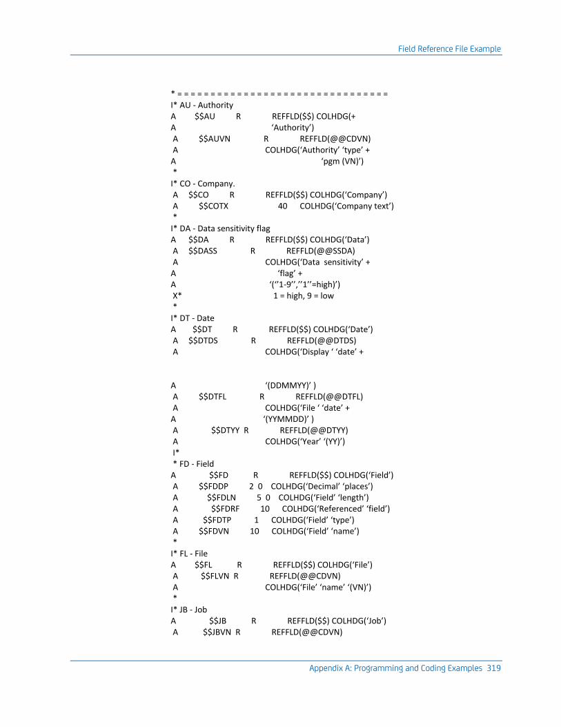
Field Reference File Example
Appendix A: Programming and Coding Examples 319
* = = = = = = = = = = = = = = = = = = = = = = = = = = = = = = = = I* AU - Authority A $$AU R REFFLD($$) COLHDG(+ A ‘Authority’) A $$AUVN R REFFLD(@@CDVN) A COLHDG(‘Authority’ ‘type’ + A ‘pgm (VN)’) * I* CO - Company. A $$CO R REFFLD($$) COLHDG(‘Company’) A $$COTX 40 COLHDG(‘Company text’) * I* DA - Data sensitivity flag A $$DA R REFFLD($$) COLHDG(‘Data’) A $$DASS R REFFLD(@@SSDA) A COLHDG(‘Data sensitivity’ + A ‘flag’ + A ‘(‘’1-9’’,’’1’’=high)’) X* 1 = high, 9 = low * I* DT - Date A $$DT R REFFLD($$) COLHDG(‘Date’) A $$DTDS R REFFLD(@@DTDS) A COLHDG(‘Display ‘ ‘date’ + A ‘(DDMMYY)’ ) A $$DTFL R REFFLD(@@DTFL) A COLHDG(‘File ‘ ‘date’ + A ‘(YYMMDD)’ ) A $$DTYY R REFFLD(@@DTYY) A COLHDG(‘Year’ ‘(YY)’) I* * FD - Field A $$FD R REFFLD($$) COLHDG(‘Field’) A $$FDDP 2 0 COLHDG(‘Decimal’ ‘places’) A $$FDLN 5 0 COLHDG(‘Field’ ‘length’) A $$FDRF 10 COLHDG(‘Referenced’ ‘field’) A $$FDTP 1 COLHDG(‘Field’ ‘type’) A $$FDVN 10 COLHDG(‘Field’ ‘name’) * I* FL - File A $$FL R REFFLD($$) COLHDG(‘File’) A $$FLVN R REFFLD(@@CDVN) A COLHDG(‘File’ ‘name’ ‘(VN)’) * I* JB - Job A $$JB R REFFLD($$) COLHDG(‘Job’) A $$JBVN R REFFLD(@@CDVN)
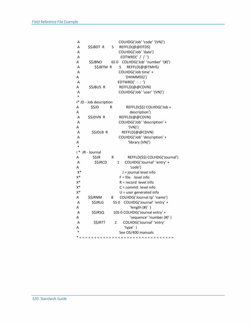
Field Reference File Example
320 Standards Guide
A COLHDG(‘Job’ ‘code’ ‘(VN)’) A $$JBDT R S REFFLD(@@DTDS) A COLHDG(‘Job’ ‘date’) A EDTWRD(‘ / / ‘) A $$JBNO 6S 0 COLHDG(‘Job’ ‘number’ ‘(#)’) A $$JBTM R S REFFLD(@@TMHS) A COLHDG(‘Job time’ + A ‘(HHMMSS)’) A EDTWRD(‘ : : ‘) A $$JBUS R REFFLD(@@CDVN) A COLHDG(‘Job’ ‘user’ ‘(VN)’) * I* JD - Job description A $$JD R REFFLD($$) COLHDG(‘Job + A description’) A $$JDVN R REFFLD(@@CDVN) A COLHDG(‘Job’ ‘description’ + A ‘(VN)’) A $$JDLB R REFFLD(@@CDVN) A COLHDG(‘Job’ ‘description’ + A ‘library (VN)’) * I * JR - Journal A $$JR R REFFLD($$) COLHDG(‘Journal’) A $$JRCD 1 COLHDG(‘Journal’ ‘entry’ + A ‘code’) X* J = journal level info X* F = file level info X* R = record level info X* C = commit level info X* U = user generated info A $$JRNM 8 COLHDG(‘Journal tp’ ‘name’) A $$JRLG 5S 0 COLHDG(‘Journal’ ‘entry’ + A ‘length (#)’ ) A $$JRSQ 10S 0 COLHDG(‘Journal entry’ + A ‘sequence’ ‘number (#)’ ) A $$JRTT 2 COLHDG(‘Journal’ ‘entry’ A ‘type’ ) * See OS/400 manuals * = = = = = = = = = = = = = = = = = = = = = = = = = = = = = = = =
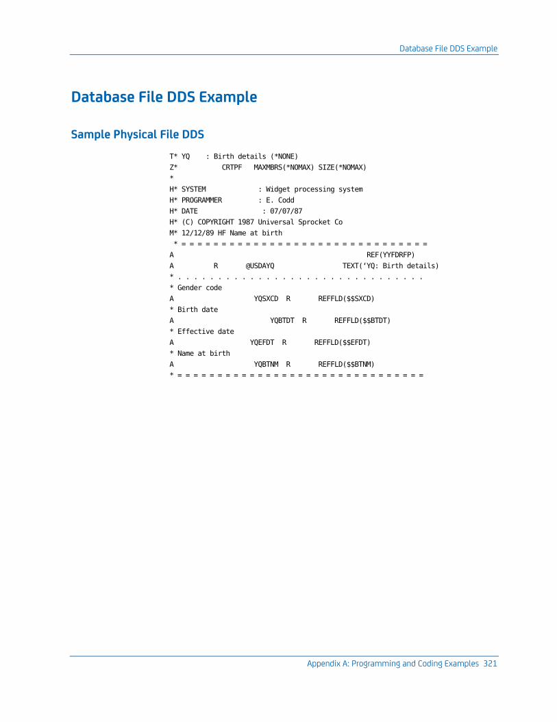
Database File DDS Example
Appendix A: Programming and Coding Examples 321
Database File DDS Example
Sample Physical File DDS
T* YQ : Birth details (*NONE)
Z* CRTPF MAXMBRS(*NOMAX) SIZE(*NOMAX)
*
H* SYSTEM : Widget processing system
H* PROGRAMMER : E. Codd
H* DATE : 07/07/87
H* (C) COPYRIGHT 1987 Universal Sprocket Co
M* 12/12/89 HF Name at birth
* = = = = = = = = = = = = = = = = = = = = = = = = = = = = = = =
A REF(YYFDRFP)
A R @USDAYQ TEXT(‘YQ: Birth details)
* . . . . . . . . . . . . . . . . . . . . . . . . . . . . . . .
* Gender code
A YQSXCD R REFFLD($$SXCD)
* Birth date
A YQBTDT R REFFLD($$BTDT)
* Effective date
A YQEFDT R REFFLD($$EFDT)
* Name at birth
A YQBTNM R REFFLD($$BTNM)
* = = = = = = = = = = = = = = = = = = = = = = = = = = = = = = =
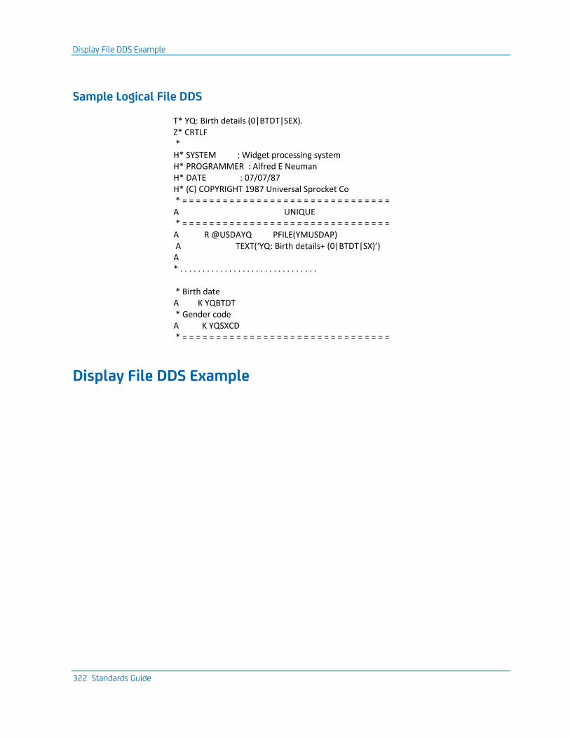
Display File DDS Example
322 Standards Guide
Sample Logical File DDS
T* YQ: Birth details (0|BTDT|SEX). Z* CRTLF * H* SYSTEM : Widget processing system H* PROGRAMMER : Alfred E Neuman H* DATE : 07/07/87 H* (C) COPYRIGHT 1987 Universal Sprocket Co * = = = = = = = = = = = = = = = = = = = = = = = = = = = = = = = A UNIQUE * = = = = = = = = = = = = = = = = = = = = = = = = = = = = = = = A R @USDAYQ PFILE(YMUSDAP) A TEXT(‘YQ: Birth details+ (0|BTDT|SX)’) A * . . . . . . . . . . . . . . . . . . . . . . . . . . . . . . . * Birth date A K YQBTDT * Gender code A K YQSXCD * = = = = = = = = = = = = = = = = = = = = = = = = = = = = = = =
Display File DDS Example
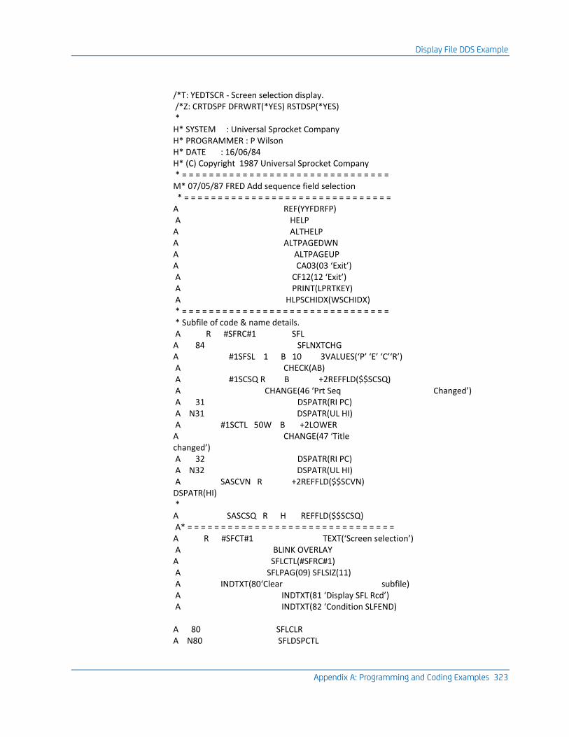
Display File DDS Example
Appendix A: Programming and Coding Examples 323
/*T: YEDTSCR - Screen selection display. /*Z: CRTDSPF DFRWRT(*YES) RSTDSP(*YES) * H* SYSTEM : Universal Sprocket Company H* PROGRAMMER : P Wilson H* DATE : 16/06/84 H* (C) Copyright 1987 Universal Sprocket Company * = = = = = = = = = = = = = = = = = = = = = = = = = = = = = = = M* 07/05/87 FRED Add sequence field selection * = = = = = = = = = = = = = = = = = = = = = = = = = = = = = = = A REF(YYFDRFP) A HELP A ALTHELP A ALTPAGEDWN A ALTPAGEUP A CA03(03 ‘Exit’) A CF12(12 ‘Exit’) A PRINT(LPRTKEY) A HLPSCHIDX(WSCHIDX) * = = = = = = = = = = = = = = = = = = = = = = = = = = = = = = = * Subfile of code & name details. A R #SFRC#1 SFL A 84 SFLNXTCHG A #1SFSL 1 B 10 3VALUES(‘P’ ‘E’ ‘C’‘R’) A CHECK(AB) A #1SCSQ R B +2REFFLD($$SCSQ) A CHANGE(46 ‘Prt Seq Changed’) A 31 DSPATR(RI PC) A N31 DSPATR(UL HI) A #1SCTL 50W B +2LOWER A CHANGE(47 ‘Title changed’) A 32 DSPATR(RI PC) A N32 DSPATR(UL HI) A SASCVN R +2REFFLD($$SCVN) DSPATR(HI) * A SASCSQ R H REFFLD($$SCSQ) A* = = = = = = = = = = = = = = = = = = = = = = = = = = = = = = = A R #SFCT#1 TEXT(‘Screen selection’) A BLINK OVERLAY A SFLCTL(#SFRC#1) A SFLPAG(09) SFLSIZ(11) A INDTXT(80‘Clear subfile) A INDTXT(81 ‘Display SFL Rcd’) A INDTXT(82 ‘Condition SLFEND) A 80 SFLCLR A N80 SFLDSPCTL
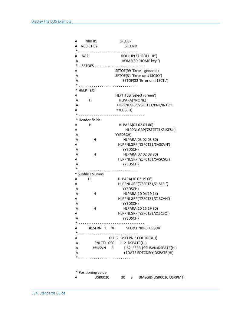
Display File DDS Example
324 Standards Guide
A N80 81 SFLDSP A N80 81 82 SFLEND * . . . . . . . . . . . . . . . . . . . . . . . . . . . . . . . A N82 ROLLUP(27 ‘ROLL UP’) A HOME(30 ‘HOME key.’) *. . SETOFS . . . . . . . . . . . . . . . . . . . . . . . . . . A SETOF(99 ‘Error - general’) A SETOF(31 ‘Error on #1SCSQ’) A SETOF(32 ‘Error on #1SCTL’) * . . . . . . . . . . . . . . . . . . . . . . . . . . . . . . . * HELP TEXT A HLPTITLE(‘Select screen’) A H HLPARA(*NONE) A HLPPNLGRP(‘ZSFCTZ1/PNL/INTRO A YYEDSCH) * - - - - - - - - - - - - - - - - - - - - - - - - - - - - - - - * Header fields A H HLPARA(03 02 03 80) A HLPPNLGRP(‘ZSFCTZ1/Z1SFSL’) A YYEDSCH) A H HLPARA(05 02 05 80) A HLPPNLGRP(‘ZSFCTZ1/SASCVN’) A YYEDSCH) A H HLPARA(07 02 08 80) A HLPPNLGRP(‘ZSFCTZ1/SASCSQ’) A YYEDSCH) * . . . . . . . . . . . . . . . . . . . . . . . . . . . . . . . * Subfile columns A H HLPARA(10 03 19 06) A HLPPNLGRP(‘ZSFCTZ1/Z1SFSL’) A YYEDSCH) A H HLPARA(10 04 19 14) A HLPPNLGRP(‘ZSFCTZ1/Z1SCVN’) A YYEDSCH) A H HLPARA(10 15 19 80) A HLPPNLGRP(‘ZSFCTZ1/Z1SCSQ’) A YYEDSCH) * - - - - - - - - - - - - - - - - - - - - - - - - - - - - - - - A #1SFRN 3 0H SFLRCDNBR(CURSOR) * . . . . . . . . . . . . . . . . . . . . . . . . . . . . . . . A O 1 2 ‘YSELPNL’ COLOR(BLU) A PNLTTL 050 1 12 DSPATR(HI) A ##USVN R 1 62 REFFL($$USVN)DSPATR(HI) A +1DATE EDTCDE(Y)DSPATR(HI) * . . . . . . . . . . . . . . . . . . . . . . . . . . . . . . . * Positioning value A USR0020 30 3 3MSGID(USR0020 USRPMT)
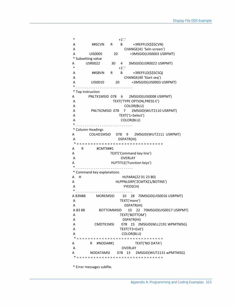
Display File DDS Example
Appendix A: Programming and Coding Examples 325
* +1’.’ A ##SCVN R B +3REFFLD($$SCVN) A CHANGE(41 ‘Seln screen’) A UIS0005 20 +3MSGID(UIS0003 USRPMT) * Subsetting value A USR0022 30 4 3MSGID(USR0022 USRPMT) * +1’.’ A ##SBVN R B +3REFFLD($$SCSQ) A CHANGE(40 ‘Start seq’) A UIS0010 20 +3MSGID(UIS0003 USRPMT) * . . . . . . . . . . . . . . . . . . . . . . . . . . . . . . . * Top instruction A PNLTX1MSID 078 6 2MSGID(UIS0008 USRPMT) A TEXT(‘TYPE OPTION,PRESS E’) A COLOR(BLU) A PNLTX2MSID 078 7 2MSGID(WUT2110 USRPMT) A TEXT(‘1=Select’) A COLOR(BLU) * . . . . . . . . . . . . . . . . . . . . . . . . . . . . . . . * Column Headings A COLHD1MSID 078 9 2MSGID(WUT2111 USRPMT) A DSPATR(HI) * = = = = = = = = = = = = = = = = = = = = = = = = = = = = = = = A R #CMTX##1 A TEXT(‘Command key line’) A OVERLAY A HLPTITLE(‘Function keys’) * . . . . . . . . . . . . . . . . . . . . . . . . . . . . . . . * Command key explanations A H HLPARA(22 01 23 80) A HLPPNLGRP(‘ZCMTXZ1/BOTINS’) A YYEDSCH) * . . . . . . . . . . . . . . . . . . . . . . . . . . . . . . . A 83N88 MOREMSID 10 28 70MSGID(UIS0016 USRPMT) A TEXT(‘more’) A DSPATR(HI) A 83 88 BOTTOMMSID 10 22 70MSGID(UIS0017 USRPMT) A TEXT(‘BOTTOM’) A DSPATR(HI) A CMDTX1MSI 078 23 2MSGID(WLL2191 WPMTMSG) A TEXT(‘F3=Exit’) A COLOR(BLU) * = = = = = = = = = = = = = = = = = = = = = = = = = = = = = = = A R #NODA##1 TEXT(‘NO DATA’) A OVERLAY A NODATAMSI 078 13 2MSGID(WUT2131 wPMTMSG) * = = = = = = = = = = = = = = = = = = = = = = = = = = = = = = = * Error messages subfile.
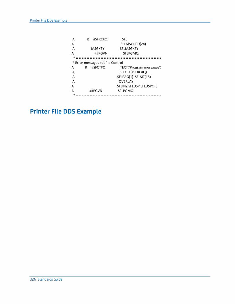
Printer File DDS Example
326 Standards Guide
A R #SFRC#Q SFL A SFLMSGRCD(24) A MSGKEY SFLMSGKEY A ##PGVN SFLPGMQ * = = = = = = = = = = = = = = = = = = = = = = = = = = = = = = = * Error messages subfile Control A R #SFCT#Q TEXT(‘Program messages’) A SFLCTL(#SFRC#Q) A SFLPAG(1) SFLSIZ(15) A OVERLAY A SFLINZ SFLDSP SFLDSPCTL A ##PGVN SFLPGMQ * = = = = = = = = = = = = = = = = = = = = = = = = = = = = = = =
Printer File DDS Example
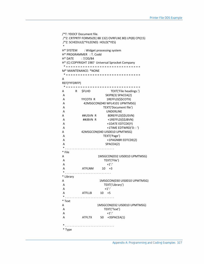
Printer File DDS Example
Appendix A: Programming and Coding Examples 327
/*T: YDOCF Document file. /*Z: CRTPRTF FORMSIZE( 88 132) OVRFLW( 80) LPI(8) CPI(15) /*Z: SCHEDULE(*FILEEND) HOLD(*YES) * H* SYSTEM : Widget processing system H* PROGRAMMER : T. Codd H* DATE : 7/20/84 H* (C) COPYRIGHT 1987 Universal Sprocket Company * = = = = = = = = = = = = = = = = = = = = = = = = = = = = = = = M* MAINTENANCE: *NONE * = = = = = = = = = = = = = = = = = = = = = = = = = = = = = = = A REF(YYFDRFP) * = = = = = = = = = = = = = = = = = = = = = = = = = = = = = = = A R $FLHD TEXT(‘File headings.’) A SKIPB(3) SPACEA(2) A YYCOTX R 1REFFLD($$COTX) A 42MSGCON(040 WFL4101 UPMTMSG) A TEXT(‘Document file’) A UNDERLINE A ##USVN R 80REFFLD($$USVN) A ##JBVN R +1REFFLD($$JBVN) A +1DATE EDTCDE(Y) A +1TIME EDTWRD(‘0: : ‘) A 42MSGCON(040 UIS0010 UPMTMSG) A TEXT(‘Page’) A +1PAGNBR EDTCDE(Z) A SPACEA(2) * . . . . . . . . . . . . . . . . . . . . . . . . . . . . . . . * File A 1MSGCON(032 UIS0010 UPMTMSG) A TEXT(‘File’) A +1’:’ A ATFLNM 10 +3 * . . . . . . . . . . . . . . . . . . . . . . . . . . . . . * Library A 1MSGCON(030 UIS0010 UPMTMSG) A TEXT(‘Library’) A +1’:’ A ATFLLB 10 +5 * . . . . . . . . . . . . . . . . . . . . . . . . . . . . . . . * Text A 1MSGCON(032 UIS0010 UPMTMSG) A TEXT(‘Text’) A +1’:’ A ATFLTX 50 +3SPACEA(1) * . . . . . . . . . . . . . . . . . . . . . . . . . . . . . . . * Type
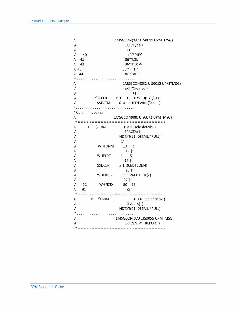
Printer File DDS Example
328 Standards Guide
A 1MSGCON(032 UIS0011 UPMTMSG) A TEXT(‘Type’) A +1’:’ A 40 +3’*PHY’ A 41 36’*LGL’ A 42 36’*DDSPF’ A 43 36’*PRTF’ A 44 36’*TAPF’ * . . . . . . . . . . . . . . . . . . . . . . . . . . . . . . . A 1MSGCON(032 UIS0012 UPMTMSG) A TEXT(‘Created’) A +1’:’ A $$FCDT 6 0 +3EDTWRD(‘ / / 0’) A $$FCTM 6 0 +1EDTWRD(‘0 : : ‘) * . . . . . . . . . . . . . . . . . . . . . . . . . . . . . . . * Column headings A 1MSGCON(080 UIS0072 UPMTMSG) * = = = = = = = = = = = = = = = = = = = = = = = = = = = = = = = A R $FDDA TEXT(‘Field details.’) A SPACEA(1) A INDTXT(91 ‘DETAIL(*FULL)’) A 1’|’ A WHFDNM 10 2 A 12’|’ A WHFLDT 1 15 A 17’|’ A $$DCLN 3 1 20EDTCDE(4) A 25’|’ A WHFDDB 5 0 26EDTCDE(Z) A 32’|’ A 91 WHFDTX 50 33 A 91 83’|’ * = = = = = = = = = = = = = = = = = = = = = = = = = = = = = = = A R $ENDA TEXT(‘End of data.’) A SPACEA(1) A INDTXT(91 ‘DETAIL(*FULL)’) * . . . . . . . . . . . . . . . . . . . . . . . . . . . . . . . A 1MSGCON(070 UIS0055 UPMTMSG) A TEXT(‘ENDOF REPORT’) * = = = = = = = = = = = = = = = = = = = = = = = = = = = = = = =
CL Program Source Example
Appendix A: Programming and Coding Examples 329
CL Program Source Example
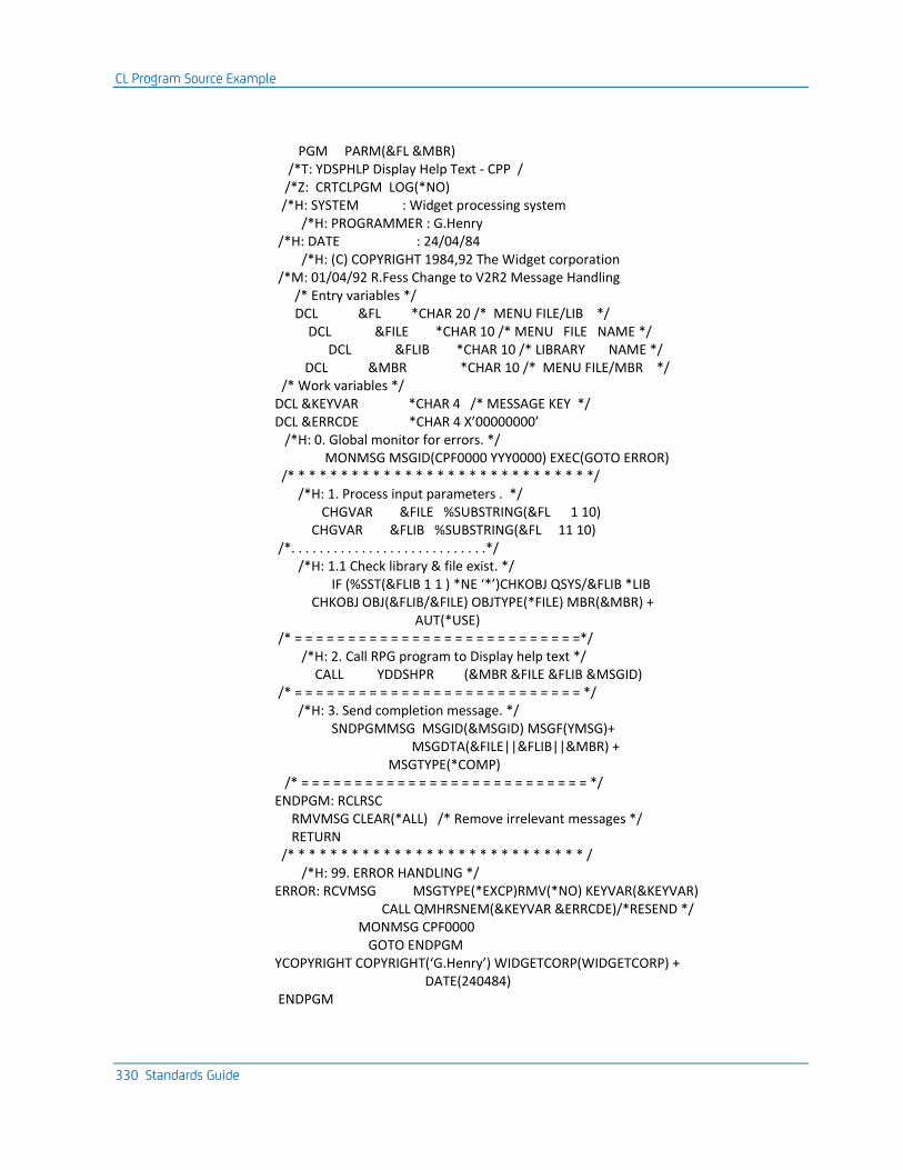
CL Program Source Example
330 Standards Guide
PGM PARM(&FL &MBR) /*T: YDSPHLP Display Help Text - CPP / /*Z: CRTCLPGM LOG(*NO) /*H: SYSTEM : Widget processing system /*H: PROGRAMMER : G.Henry /*H: DATE : 24/04/84 /*H: (C) COPYRIGHT 1984,92 The Widget corporation /*M: 01/04/92 R.Fess Change to V2R2 Message Handling /* Entry variables */ DCL &FL *CHAR 20 /* MENU FILE/LIB */ DCL &FILE *CHAR 10 /* MENU FILE NAME */ DCL &FLIB *CHAR 10 /* LIBRARY NAME */ DCL &MBR *CHAR 10 /* MENU FILE/MBR */ /* Work variables */ DCL &KEYVAR *CHAR 4 /* MESSAGE KEY */ DCL &ERRCDE *CHAR 4 X’00000000’ /*H: 0. Global monitor for errors. */ MONMSG MSGID(CPF0000 YYY0000) EXEC(GOTO ERROR) /* * * * * * * * * * * * * * * * * * * * * * * * * * * * */ /*H: 1. Process input parameters . */ CHGVAR &FILE %SUBSTRING(&FL 1 10) CHGVAR &FLIB %SUBSTRING(&FL 11 10) /*. . . . . . . . . . . . . . . . . . . . . . . . . . . .*/ /*H: 1.1 Check library & file exist. */ IF (%SST(&FLIB 1 1 ) *NE ‘*’)CHKOBJ QSYS/&FLIB *LIB CHKOBJ OBJ(&FLIB/&FILE) OBJTYPE(*FILE) MBR(&MBR) + AUT(*USE) /* = = = = = = = = = = = = = = = = = = = = = = = = = = =*/ /*H: 2. Call RPG program to Display help text */ CALL YDDSHPR (&MBR &FILE &FLIB &MSGID) /* = = = = = = = = = = = = = = = = = = = = = = = = = = = */ /*H: 3. Send completion message. */ SNDPGMMSG MSGID(&MSGID) MSGF(YMSG)+ MSGDTA(&FILE||&FLIB||&MBR) + MSGTYPE(*COMP) /* = = = = = = = = = = = = = = = = = = = = = = = = = = = */ ENDPGM: RCLRSC RMVMSG CLEAR(*ALL) /* Remove irrelevant messages */ RETURN /* * * * * * * * * * * * * * * * * * * * * * * * * * * * / /*H: 99. ERROR HANDLING */ ERROR: RCVMSG MSGTYPE(*EXCP)RMV(*NO) KEYVAR(&KEYVAR) CALL QMHRSNEM(&KEYVAR &ERRCDE)/*RESEND */ MONMSG CPF0000 GOTO ENDPGM YCOPYRIGHT COPYRIGHT(‘G.Henry’) WIDGETCORP(WIDGETCORP) + DATE(240484) ENDPGM
RPG III Program Source Example
Appendix A: Programming and Coding Examples 331
RPG III Program Source Example
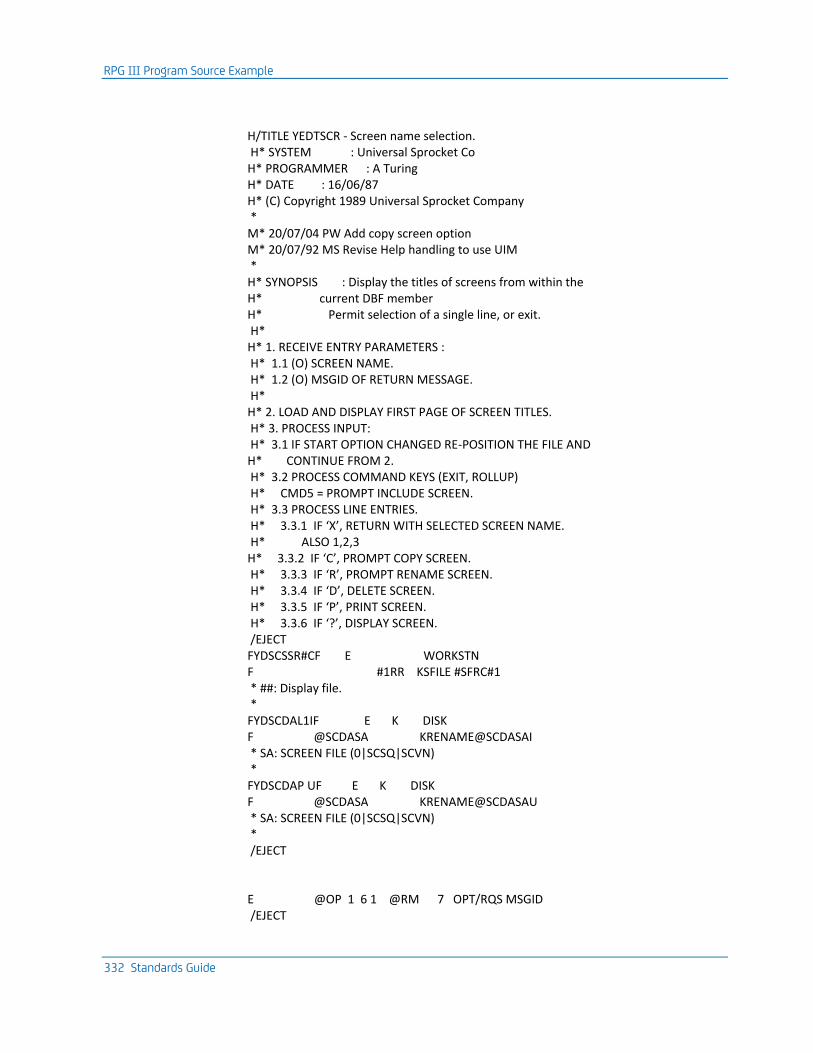
RPG III Program Source Example
332 Standards Guide
H/TITLE YEDTSCR - Screen name selection. H* SYSTEM : Universal Sprocket Co H* PROGRAMMER : A Turing H* DATE : 16/06/87 H* (C) Copyright 1989 Universal Sprocket Company * M* 20/07/04 PW Add copy screen option M* 20/07/92 MS Revise Help handling to use UIM * H* SYNOPSIS : Display the titles of screens from within the H* current DBF member H* Permit selection of a single line, or exit. H* H* 1. RECEIVE ENTRY PARAMETERS : H* 1.1 (O) SCREEN NAME. H* 1.2 (O) MSGID OF RETURN MESSAGE. H* H* 2. LOAD AND DISPLAY FIRST PAGE OF SCREEN TITLES. H* 3. PROCESS INPUT: H* 3.1 IF START OPTION CHANGED RE-POSITION THE FILE AND H* CONTINUE FROM 2. H* 3.2 PROCESS COMMAND KEYS (EXIT, ROLLUP) H* CMD5 = PROMPT INCLUDE SCREEN. H* 3.3 PROCESS LINE ENTRIES. H* 3.3.1 IF ‘X’, RETURN WITH SELECTED SCREEN NAME. H* ALSO 1,2,3 H* 3.3.2 IF ‘C’, PROMPT COPY SCREEN. H* 3.3.3 IF ‘R’, PROMPT RENAME SCREEN. H* 3.3.4 IF ‘D’, DELETE SCREEN. H* 3.3.5 IF ‘P’, PRINT SCREEN. H* 3.3.6 IF ‘?’, DISPLAY SCREEN. /EJECT FYDSCSSR#CF E WORKSTN F #1RR KSFILE #SFRC#1 * ##: Display file. * FYDSCDAL1IF E K DISK F @SCDASA KRENAME@SCDASAI * SA: SCREEN FILE (0|SCSQ|SCVN) * FYDSCDAP UF E K DISK F @SCDASA KRENAME@SCDASAU * SA: SCREEN FILE (0|SCSQ|SCVN) * /EJECT E @OP 1 6 1 @RM 7 OPT/RQS MSGID /EJECT
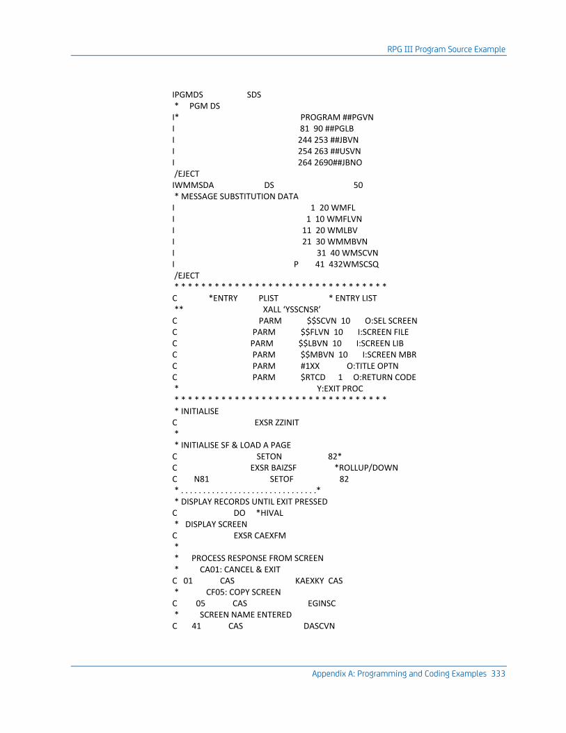
RPG III Program Source Example
Appendix A: Programming and Coding Examples 333
IPGMDS SDS * PGM DS I* PROGRAM ##PGVN I 81 90 ##PGLB I 244 253 ##JBVN I 254 263 ##USVN I 264 2690##JBNO /EJECT IWMMSDA DS 50 * MESSAGE SUBSTITUTION DATA I 1 20 WMFL I 1 10 WMFLVN I 11 20 WMLBV I 21 30 WMMBVN I 31 40 WMSCVN I P 41 432WMSCSQ /EJECT * * * * * * * * * * * * * * * * * * * * * * * * * * * * * * * * C *ENTRY PLIST * ENTRY LIST ** XALL ‘YSSCNSR’ C PARM $$SCVN 10 O:SEL SCREEN C PARM $$FLVN 10 I:SCREEN FILE C PARM $$LBVN 10 I:SCREEN LIB C PARM $$MBVN 10 I:SCREEN MBR C PARM #1XX O:TITLE OPTN C PARM $RTCD 1 O:RETURN CODE * Y:EXIT PROC * * * * * * * * * * * * * * * * * * * * * * * * * * * * * * * * * INITIALISE C EXSR ZZINIT * * INITIALISE SF & LOAD A PAGE C SETON 82* C EXSR BAIZSF *ROLLUP/DOWN C N81 SETOF 82 * . . . . . . . . . . . . . . . . . . . . . . . . . . . . . . .* * DISPLAY RECORDS UNTIL EXIT PRESSED C DO *HIVAL * DISPLAY SCREEN C EXSR CAEXFM * * PROCESS RESPONSE FROM SCREEN * CA01: CANCEL & EXIT C 01 CAS KAEXKY CAS * CF05: COPY SCREEN C 05 CAS EGINSC * SCREEN NAME ENTERED C 41 CAS DASCVN
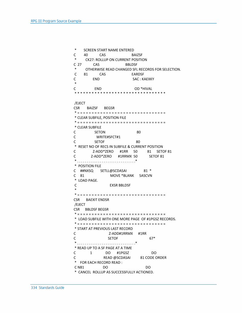
RPG III Program Source Example
334 Standards Guide
* SCREEN START NAME ENTERED C 40 CAS BAIZSF * CK27: ROLLUP ON CURRENT POSITION C 27 CAS BBLDSF * OTHERWISE READ CHANGED SFL RECORDS FOR SELECTION. C 81 CAS EARDSF C END SAC : KAEXKY * C END OD *HIVAL * * * * * * * * * * * * * * * * * * * * * * * * * * * * * * * * /EJECT CSR BAIZSF BEGSR * = = = = = = = = = = = = = = = = = = = = = = = = = = = = = = = * CLEAR SUBFILE, POSITION FILE * = = = = = = = = = = = = = = = = = = = = = = = = = = = = = = = * CLEAR SUBFILE C SETON 80 C WRITE#SFCT#1 C SETOF 80 * RESET NO OF RECS IN SUBFILE & CURRENT POSITION C Z-ADD*ZERO #1RR 50 81 SETOF 81 C Z-ADD*ZERO #1RRMX 50 SETOF 81 * . . . . . . . . . . . . . . . . . . . . . . . . . . . . . . .* * POSITION FILE C ##NXSQ SETLL@SCDASAI 81 * C 81 MOVE *BLANK SASCVN * LOAD PAGE. C EXSR BBLDSF * * = = = = = = = = = = = = = = = = = = = = = = = = = = = = = = = CSR BAEXIT ENDSR /EJECT CSR BBLDSF BEGSR * = = = = = = = = = = = = = = = = = = = = = = = = = = = = = = = * LOAD SUBFILE WITH ONE MORE PAGE OF #1PGSZ RECORDS. * = = = = = = = = = = = = = = = = = = = = = = = = = = = = = = = * START AT PREVIOUS LAST RECORD C Z-ADD#1RRMX #1RR C SETOF 67* * . . . . . . . . . . . . . . . . . . . . . . . . . . . . . . .* * READ UP TO A SF PAGE AT A TIME C 1 DO #1PGSZ DO C READ @SCDASAI 81 CODE ORDER * FOR EACH RECORD READ : C N81 DO DO * CANCEL ROLLUP AS SUCCESSFULLY ACTIONED.
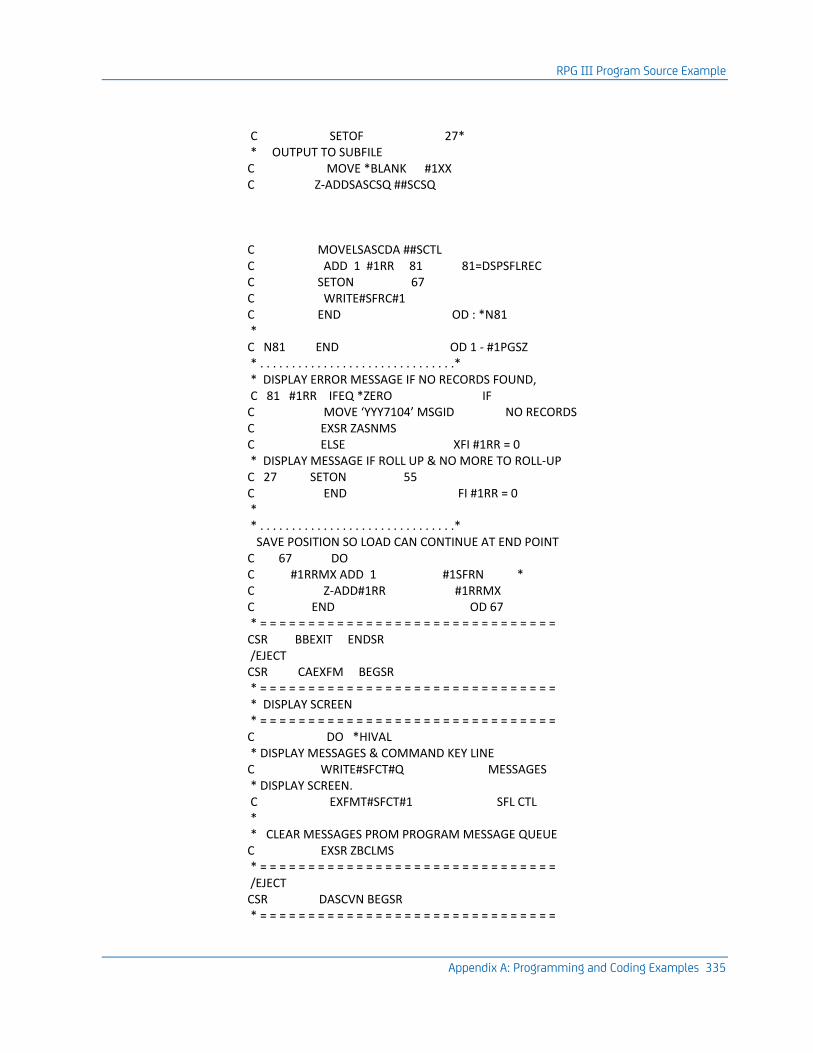
RPG III Program Source Example
Appendix A: Programming and Coding Examples 335
C SETOF 27* * OUTPUT TO SUBFILE C MOVE *BLANK #1XX C Z-ADDSASCSQ ##SCSQ C MOVELSASCDA ##SCTL C ADD 1 #1RR 81 81=DSPSFLREC C SETON 67 C WRITE#SFRC#1 C END OD : *N81 * C N81 END OD 1 - #1PGSZ * . . . . . . . . . . . . . . . . . . . . . . . . . . . . . . .* * DISPLAY ERROR MESSAGE IF NO RECORDS FOUND, C 81 #1RR IFEQ *ZERO IF C MOVE ‘YYY7104’ MSGID NO RECORDS C EXSR ZASNMS C ELSE XFI #1RR = 0 * DISPLAY MESSAGE IF ROLL UP & NO MORE TO ROLL-UP C 27 SETON 55 C END FI #1RR = 0 * * . . . . . . . . . . . . . . . . . . . . . . . . . . . . . . .* SAVE POSITION SO LOAD CAN CONTINUE AT END POINT C 67 DO C #1RRMX ADD 1 #1SFRN * C Z-ADD#1RR #1RRMX C END OD 67 * = = = = = = = = = = = = = = = = = = = = = = = = = = = = = = = CSR BBEXIT ENDSR /EJECT CSR CAEXFM BEGSR * = = = = = = = = = = = = = = = = = = = = = = = = = = = = = = = * DISPLAY SCREEN * = = = = = = = = = = = = = = = = = = = = = = = = = = = = = = = C DO *HIVAL * DISPLAY MESSAGES & COMMAND KEY LINE C WRITE#SFCT#Q MESSAGES * DISPLAY SCREEN. C EXFMT#SFCT#1 SFL CTL * * CLEAR MESSAGES PROM PROGRAM MESSAGE QUEUE C EXSR ZBCLMS * = = = = = = = = = = = = = = = = = = = = = = = = = = = = = = = /EJECT CSR DASCVN BEGSR * = = = = = = = = = = = = = = = = = = = = = = = = = = = = = = =
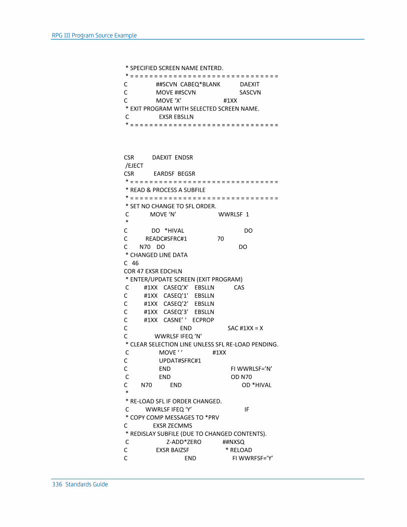
RPG III Program Source Example
336 Standards Guide
* SPECIFIED SCREEN NAME ENTERD. * = = = = = = = = = = = = = = = = = = = = = = = = = = = = = = = C ##SCVN CABEQ*BLANK DAEXIT C MOVE ##SCVN SASCVN C MOVE ‘X’ #1XX * EXIT PROGRAM WITH SELECTED SCREEN NAME. C EXSR EBSLLN * = = = = = = = = = = = = = = = = = = = = = = = = = = = = = = = CSR DAEXIT ENDSR /EJECT CSR EARDSF BEGSR * = = = = = = = = = = = = = = = = = = = = = = = = = = = = = = = * READ & PROCESS A SUBFILE * = = = = = = = = = = = = = = = = = = = = = = = = = = = = = = = * SET NO CHANGE TO SFL ORDER. C MOVE ‘N’ WWRLSF 1 * C DO *HIVAL DO C READC#SFRC#1 70 C N70 DO DO * CHANGED LINE DATA C 46 COR 47 EXSR EDCHLN * ENTER/UPDATE SCREEN (EXIT PROGRAM) C #1XX CASEQ’X’ EBSLLN CAS C #1XX CASEQ’1’ EBSLLN C #1XX CASEQ’2’ EBSLLN C #1XX CASEQ’3’ EBSLLN C #1XX CASNE’ ‘ ECPROP C END SAC #1XX = X C WWRLSF IFEQ ‘N’ * CLEAR SELECTION LINE UNLESS SFL RE-LOAD PENDING. C MOVE ‘ ‘ #1XX C UPDAT#SFRC#1 C END FI WWRLSF=’N’ C END OD N70 C N70 END OD *HIVAL * * RE-LOAD SFL IF ORDER CHANGED. C WWRLSF IFEQ ‘Y’ IF * COPY COMP MESSAGES TO *PRV C EXSR ZECMMS * REDISLAY SUBFILE (DUE TO CHANGED CONTENTS). C Z-ADD*ZERO ##NXSQ C EXSR BAIZSF * RELOAD C END FI WWRFSF=’Y’
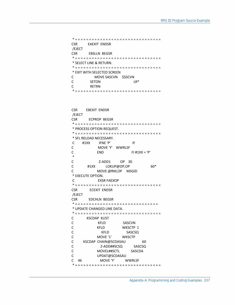
RPG III Program Source Example
Appendix A: Programming and Coding Examples 337
* = = = = = = = = = = = = = = = = = = = = = = = = = = = = = = = CSR EAEXIT ENDSR /EJECT CSR EBSLLN BEGSR * = = = = = = = = = = = = = = = = = = = = = = = = = = = = = = = * SELECT LINE & RETURN. * = = = = = = = = = = = = = = = = = = = = = = = = = = = = = = = * EXIT WITH SELECTED SCREEN C MOVE SASCVN $$SCVN C SETON LR* C RETRN * = = = = = = = = = = = = = = = = = = = = = = = = = = = = = = = CSR EBEXIT ENDSR /EJECT CSR ECPROP BEGSR * = = = = = = = = = = = = = = = = = = = = = = = = = = = = = = = * PROCESS OPTION REQUEST. * = = = = = = = = = = = = = = = = = = = = = = = = = = = = = = = * SFL RELOAD NECESSARY. C #1XX IFNE ‘P’ IF C MOVE ‘Y’ WWRLSF C END FI #1XX = ‘P’ * C Z-ADD1 OP 30 C #1XX LOKUP@OP,OP 60* C MOVE @RM,OP MSGID * EXECUTE OPTION. C EXSR FAEXOP * = = = = = = = = = = = = = = = = = = = = = = = = = = = = = = = CSR ECEXIT ENDSR /EJECT CSR EDCHLN BEGSR * = = = = = = = = = = = = = = = = = = = = = = = = = = = = = = * UPDATE CHANGED LINE DATA. * = = = = = = = = = = = = = = = = = = = = = = = = = = = = = = = C KSCDAP KLIST C KFLD SASCVN C KFLD WKSCTP 1 C KFLD SASCSQ C MOVE ‘1’ WKSCTP C KSCDAP CHAIN@SCDASAU 60 C Z-ADD##SCSQ SASCSQ C MOVEL##SCTL SASCDA C UPDAT@SCDASAU C 46 MOVE ‘Y’ WWRLSF * = = = = = = = = = = = = = = = = = = = = = = = = = = = = = = =
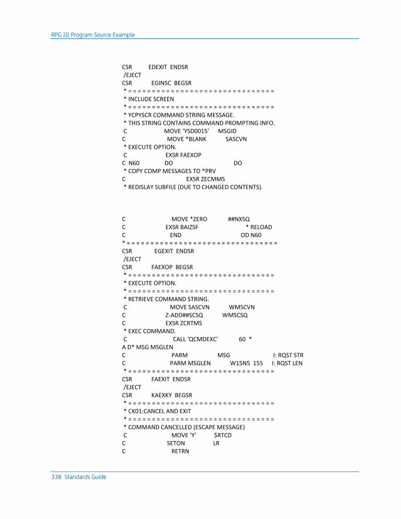
RPG III Program Source Example
338 Standards Guide
CSR EDEXIT ENDSR /EJECT CSR EGINSC BEGSR * = = = = = = = = = = = = = = = = = = = = = = = = = = = = = = = * INCLUDE SCREEN * = = = = = = = = = = = = = = = = = = = = = = = = = = = = = = = * YCPYSCR COMMAND STRING MESSAGE. * THIS STRING CONTAINS COMMAND PROMPTING INFO. C MOVE ‘YSD0015’ MSGID C MOVE *BLANK SASCVN * EXECUTE OPTION. C EXSR FAEXOP C N60 DO DO * COPY COMP MESSAGES TO *PRV C EXSR ZECMMS * REDISLAY SUBFILE (DUE TO CHANGED CONTENTS). C MOVE *ZERO ##NXSQ C EXSR BAIZSF * RELOAD C END OD N60 * = = = = = = = = = = = = = = = = = = = = = = = = = = = = = = = = CSR EGEXIT ENDSR /EJECT CSR FAEXOP BEGSR * = = = = = = = = = = = = = = = = = = = = = = = = = = = = = = = * EXECUTE OPTION. * = = = = = = = = = = = = = = = = = = = = = = = = = = = = = = = * RETRIEVE COMMAND STRING. C MOVE SASCVN WMSCVN C Z-ADD##SCSQ WMSCSQ C EXSR ZCRTMS * EXEC COMMAND. C CALL ‘QCMDEXC’ 60 * A D* MSG MSGLEN C PARM MSG I: RQST STR C PARM MSGLEN W15N5 155 I: RQST LEN * = = = = = = = = = = = = = = = = = = = = = = = = = = = = = = = CSR FAEXIT ENDSR /EJECT CSR KAEXKY BEGSR * = = = = = = = = = = = = = = = = = = = = = = = = = = = = = = = * CK01:CANCEL AND EXIT * = = = = = = = = = = = = = = = = = = = = = = = = = = = = = = = * COMMAND CANCELLED (ESCAPE MESSAGE) C MOVE ‘Y’ $RTCD C SETON LR C RETRN
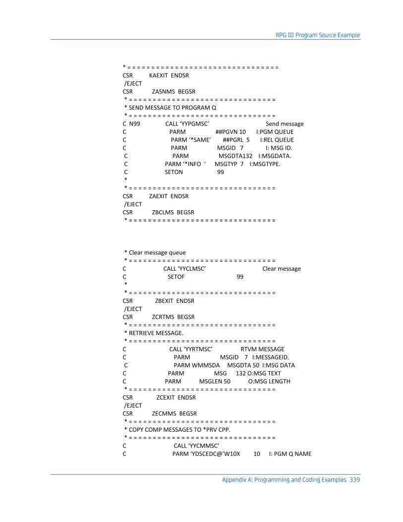
RPG III Program Source Example
Appendix A: Programming and Coding Examples 339
* = = = = = = = = = = = = = = = = = = = = = = = = = = = = = = = = CSR KAEXIT ENDSR /EJECT CSR ZASNMS BEGSR * = = = = = = = = = = = = = = = = = = = = = = = = = = = = = = = * SEND MESSAGE TO PROGRAM Q * = = = = = = = = = = = = = = = = = = = = = = = = = = = = = = = C N99 CALL ‘YYPGMSC’ Send message C PARM ##PGVN 10 I:PGM QUEUE C PARM ‘*SAME’ ##PGRL 5 I:REL QUEUE C PARM MSGID 7 I: MSG ID. C PARM MSGDTA132 I:MSGDATA. C PARM ‘*INFO ‘ MSGTYP 7 I:MSGTYPE. C SETON 99 * * = = = = = = = = = = = = = = = = = = = = = = = = = = = = = = = CSR ZAEXIT ENDSR /EJECT CSR ZBCLMS BEGSR * = = = = = = = = = = = = = = = = = = = = = = = = = = = = = = = * Clear message queue * = = = = = = = = = = = = = = = = = = = = = = = = = = = = = = = C CALL ‘YYCLMSC’ Clear message C SETOF 99 * * = = = = = = = = = = = = = = = = = = = = = = = = = = = = = = = CSR ZBEXIT ENDSR /EJECT CSR ZCRTMS BEGSR * = = = = = = = = = = = = = = = = = = = = = = = = = = = = = = = * RETRIEVE MESSAGE. * = = = = = = = = = = = = = = = = = = = = = = = = = = = = = = = C CALL ‘YYRTMSC’ RTVM MESSAGE C PARM MSGID 7 I:MESSAGEID. C PARM WMMSDA MSGDTA 50 I:MSG DATA C PARM MSG 132 O:MSG TEXT C PARM MSGLEN 50 O:MSG LENGTH * = = = = = = = = = = = = = = = = = = = = = = = = = = = = = = = CSR ZCEXIT ENDSR /EJECT CSR ZECMMS BEGSR * = = = = = = = = = = = = = = = = = = = = = = = = = = = = = = = * COPY COMP MESSAGES TO *PRV CPP. * = = = = = = = = = = = = = = = = = = = = = = = = = = = = = = = C CALL ‘YYCMMSC’ C PARM ‘YDSCEDC@’W10X 10 I: PGM Q NAME
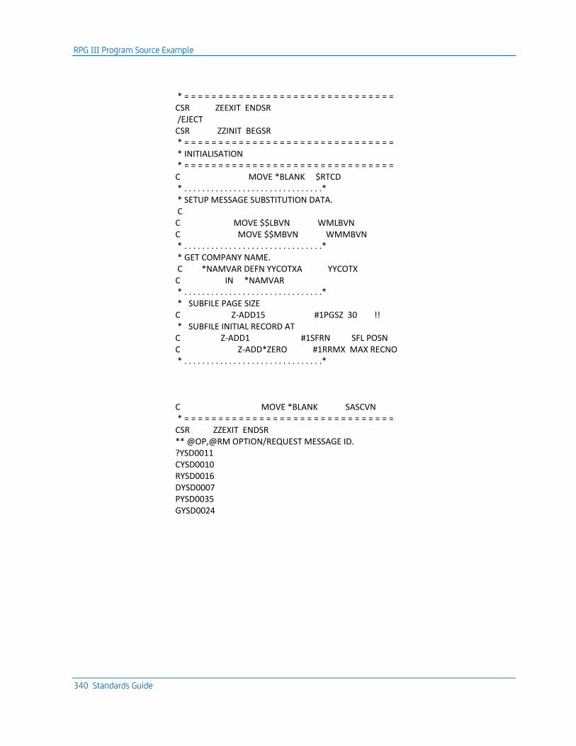
RPG III Program Source Example
340 Standards Guide
* = = = = = = = = = = = = = = = = = = = = = = = = = = = = = = = CSR ZEEXIT ENDSR /EJECT CSR ZZINIT BEGSR * = = = = = = = = = = = = = = = = = = = = = = = = = = = = = = = * INITIALISATION * = = = = = = = = = = = = = = = = = = = = = = = = = = = = = = = C MOVE *BLANK $RTCD * . . . . . . . . . . . . . . . . . . . . . . . . . . . . . . .* * SETUP MESSAGE SUBSTITUTION DATA. C C MOVE $$LBVN WMLBVN C MOVE $$MBVN WMMBVN * . . . . . . . . . . . . . . . . . . . . . . . . . . . . . . .* * GET COMPANY NAME. C *NAMVAR DEFN YYCOTXA YYCOTX C IN *NAMVAR * . . . . . . . . . . . . . . . . . . . . . . . . . . . . . . .* * SUBFILE PAGE SIZE C Z-ADD15 #1PGSZ 30 !! * SUBFILE INITIAL RECORD AT C Z-ADD1 #1SFRN SFL POSN C Z-ADD*ZERO #1RRMX MAX RECNO * . . . . . . . . . . . . . . . . . . . . . . . . . . . . . . .* C MOVE *BLANK SASCVN * = = = = = = = = = = = = = = = = = = = = = = = = = = = = = = = CSR ZZEXIT ENDSR ** @OP,@RM OPTION/REQUEST MESSAGE ID. ?YSD0011 CYSD0010 RYSD0016 DYSD0007 PYSD0035 GYSD0024
COBOL ‘85 Program Example
Appendix A: Programming and Coding Examples 341
COBOL ‘85 Program Example
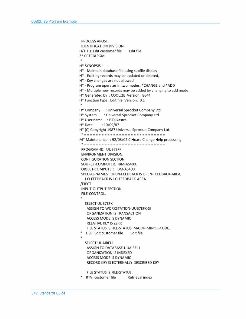
COBOL ‘85 Program Example
342 Standards Guide
PROCESS APOST. IDENTIFICATION DIVISION. H/TITLE Edit customer file Edit file Z* CRTCBLPGM * H* SYNOPSIS : H* - Maintain database file using subfile display H* - Existing records may be updated or deleted, H* - Key changes are not allowed H* - Program operates in two modes: *CHANGE and *ADD H* - Multiple new records may be added by changing to add mode H* Generated by : COOL:2E Version: 8644 H* Function type : Edit file Version: 0.1 * H* Company : Universal Sprocket Company Ltd. H* System : Universal Sprocket Company Ltd. H* User name : P.Djikastra H* Date : 10/09/87 H* (C) Copyright 1987 Universal Sprocket Company Ltd. * = = = = = = = = = = = = = = = = = = = = = = = = = = = = M* Maintenance : 92/03/02 C.Hoare Change Help processing * = = = = = = = = = = = = = = = = = = = = = = = = = = = = PROGRAM-ID. UUB7EFK. ENVIRONMENT DIVISION. CONFIGURATION SECTION. SOURCE-COMPUTER. IBM-AS400. OBJECT-COMPUTER. IBM-AS400. SPECIAL-NAMES. OPEN-FEEDBACK IS OPEN-FEEDBACK-AREA, I-O-FEEDBACK IS I-O-FEEDBACK-AREA. /EJECT INPUT-OUTPUT SECTION. FILE-CONTROL. * SELECT UUB7EFK ASSIGN TO WORKSTATION-UUB7EFK-SI ORGANIZATION IS TRANSACTION ACCESS MODE IS DYNAMIC RELATIVE KEY IS ZZRR FILE STATUS IS FILE-STATUS, MAJOR-MINOR-CODE. * DSP: Edit customer file Edit file * SELECT UUAIREL1 ASSIGN TO DATABASE-UUAIREL1 ORGANIZATION IS INDEXED ACCESS MODE IS DYNAMIC RECORD KEY IS EXTERNALLY-DESCRIBED-KEY FILE STATUS IS FILE-STATUS. * RTV: customer file Retrieval index
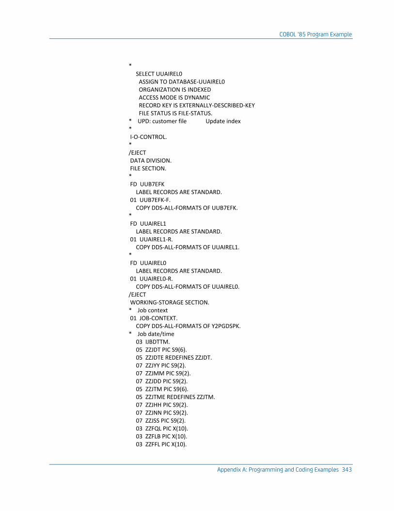
COBOL ‘85 Program Example
Appendix A: Programming and Coding Examples 343
* SELECT UUAIREL0 ASSIGN TO DATABASE-UUAIREL0 ORGANIZATION IS INDEXED ACCESS MODE IS DYNAMIC RECORD KEY IS EXTERNALLY-DESCRIBED-KEY FILE STATUS IS FILE-STATUS. * UPD: customer file Update index * I-O-CONTROL. * /EJECT DATA DIVISION. FILE SECTION. * FD UUB7EFK LABEL RECORDS ARE STANDARD. 01 UUB7EFK-F. COPY DDS-ALL-FORMATS OF UUB7EFK. * FD UUAIREL1 LABEL RECORDS ARE STANDARD. 01 UUAIREL1-R. COPY DDS-ALL-FORMATS OF UUAIREL1. * FD UUAIREL0 LABEL RECORDS ARE STANDARD. 01 UUAIREL0-R. COPY DDS-ALL-FORMATS OF UUAIREL0. /EJECT WORKING-STORAGE SECTION. * Job context 01 JOB-CONTEXT. COPY DDS-ALL-FORMATS OF Y2PGDSPK. * Job date/time 03 IJBDTTM. 05 ZZJDT PIC S9(6). 05 ZZJDTE REDEFINES ZZJDT. 07 ZZJYY PIC S9(2). 07 ZZJMM PIC S9(2). 07 ZZJDD PIC S9(2). 05 ZZJTM PIC S9(6). 05 ZZJTME REDEFINES ZZJTM. 07 ZZJHH PIC S9(2). 07 ZZJNN PIC S9(2). 07 ZZJSS PIC S9(2). 03 ZZFQL PIC X(10). 03 ZZFLB PIC X(10). 03 ZZFFL PIC X(10).
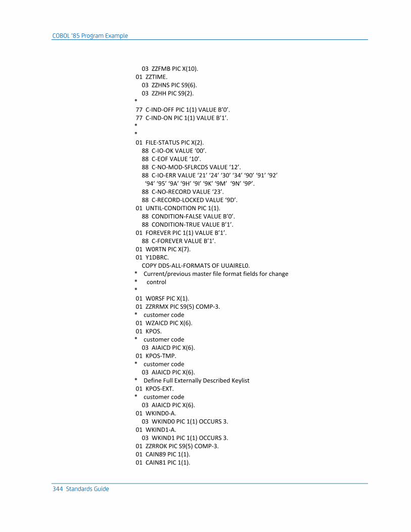
COBOL ‘85 Program Example
344 Standards Guide
03 ZZFMB PIC X(10). 01 ZZTIME. 03 ZZHNS PIC S9(6). 03 ZZHH PIC S9(2). * 77 C-IND-OFF PIC 1(1) VALUE B’0’. 77 C-IND-ON PIC 1(1) VALUE B’1’. * * 01 FILE-STATUS PIC X(2). 88 C-IO-OK VALUE ‘00’. 88 C-EOF VALUE ‘10’. 88 C-NO-MOD-SFLRCDS VALUE ‘12’. 88 C-IO-ERR VALUE ‘21’ ‘24’ ‘30’ ‘34’ ‘90’ ‘91’ ‘92’ ‘94’ ‘95’ ‘9A’ ‘9H’ ‘9I’ ‘9K’ ‘9M’ ‘9N’ ‘9P’. 88 C-NO-RECORD VALUE ‘23’. 88 C-RECORD-LOCKED VALUE ‘9D’. 01 UNTIL-CONDITION PIC 1(1). 88 CONDITION-FALSE VALUE B’0’. 88 CONDITION-TRUE VALUE B’1’. 01 FOREVER PIC 1(1) VALUE B’1’. 88 C-FOREVER VALUE B’1’. 01 W0RTN PIC X(7). 01 Y1DBRC. COPY DDS-ALL-FORMATS OF UUAIREL0. * Current/previous master file format fields for change * control * 01 W0RSF PIC X(1). 01 ZZRRMX PIC S9(5) COMP-3. * customer code 01 WZAICD PIC X(6). 01 KPOS. * customer code 03 AIAICD PIC X(6). 01 KPOS-TMP. * customer code 03 AIAICD PIC X(6). * Define Full Externally Described Keylist 01 KPOS-EXT. * customer code 03 AIAICD PIC X(6). 01 WKIND0-A. 03 WKIND0 PIC 1(1) OCCURS 3. 01 WKIND1-A. 03 WKIND1 PIC 1(1) OCCURS 3. 01 ZZRROK PIC S9(5) COMP-3. 01 CAIN89 PIC 1(1). 01 CAIN81 PIC 1(1).
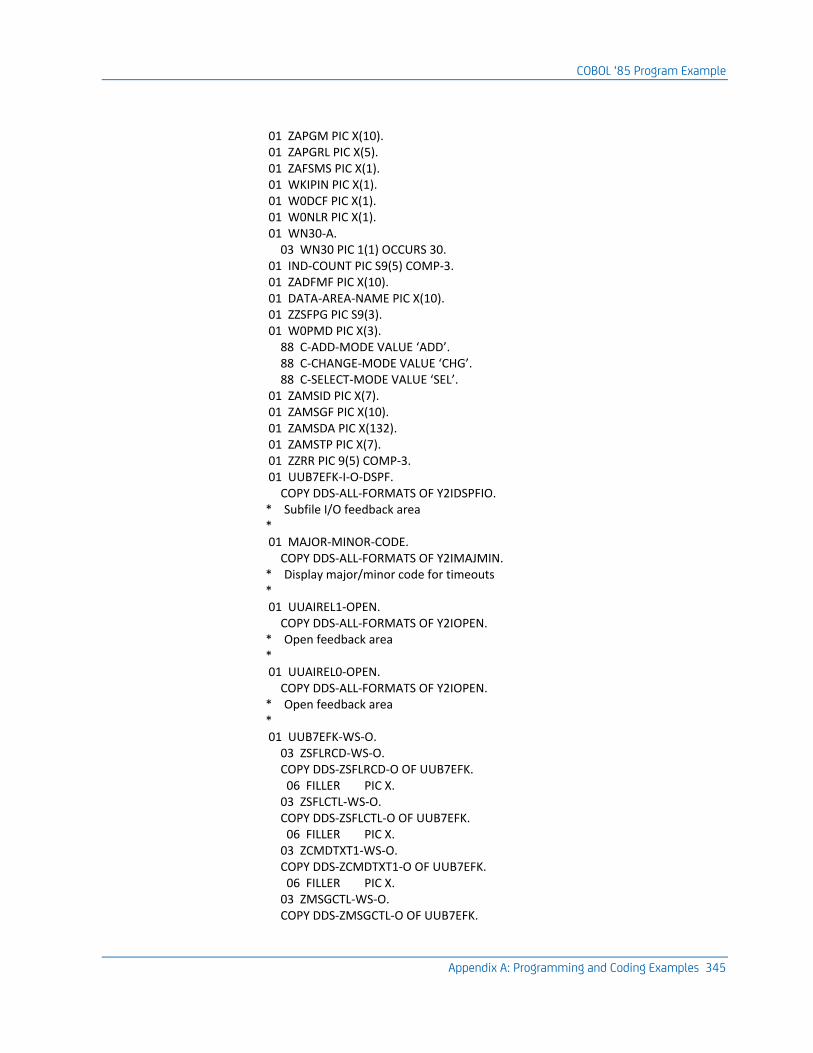
COBOL ‘85 Program Example
Appendix A: Programming and Coding Examples 345
01 ZAPGM PIC X(10). 01 ZAPGRL PIC X(5). 01 ZAFSMS PIC X(1). 01 WKIPIN PIC X(1). 01 W0DCF PIC X(1). 01 W0NLR PIC X(1). 01 WN30-A. 03 WN30 PIC 1(1) OCCURS 30. 01 IND-COUNT PIC S9(5) COMP-3. 01 ZADFMF PIC X(10). 01 DATA-AREA-NAME PIC X(10). 01 ZZSFPG PIC S9(3). 01 W0PMD PIC X(3). 88 C-ADD-MODE VALUE ‘ADD’. 88 C-CHANGE-MODE VALUE ‘CHG’. 88 C-SELECT-MODE VALUE ‘SEL’. 01 ZAMSID PIC X(7). 01 ZAMSGF PIC X(10). 01 ZAMSDA PIC X(132). 01 ZAMSTP PIC X(7). 01 ZZRR PIC 9(5) COMP-3. 01 UUB7EFK-I-O-DSPF. COPY DDS-ALL-FORMATS OF Y2IDSPFIO. * Subfile I/O feedback area * 01 MAJOR-MINOR-CODE. COPY DDS-ALL-FORMATS OF Y2IMAJMIN. * Display major/minor code for timeouts * 01 UUAIREL1-OPEN. COPY DDS-ALL-FORMATS OF Y2IOPEN. * Open feedback area * 01 UUAIREL0-OPEN. COPY DDS-ALL-FORMATS OF Y2IOPEN. * Open feedback area * 01 UUB7EFK-WS-O. 03 ZSFLRCD-WS-O. COPY DDS-ZSFLRCD-O OF UUB7EFK. 06 FILLER PIC X. 03 ZSFLCTL-WS-O. COPY DDS-ZSFLCTL-O OF UUB7EFK. 06 FILLER PIC X. 03 ZCMDTXT1-WS-O. COPY DDS-ZCMDTXT1-O OF UUB7EFK. 06 FILLER PIC X. 03 ZMSGCTL-WS-O. COPY DDS-ZMSGCTL-O OF UUB7EFK.
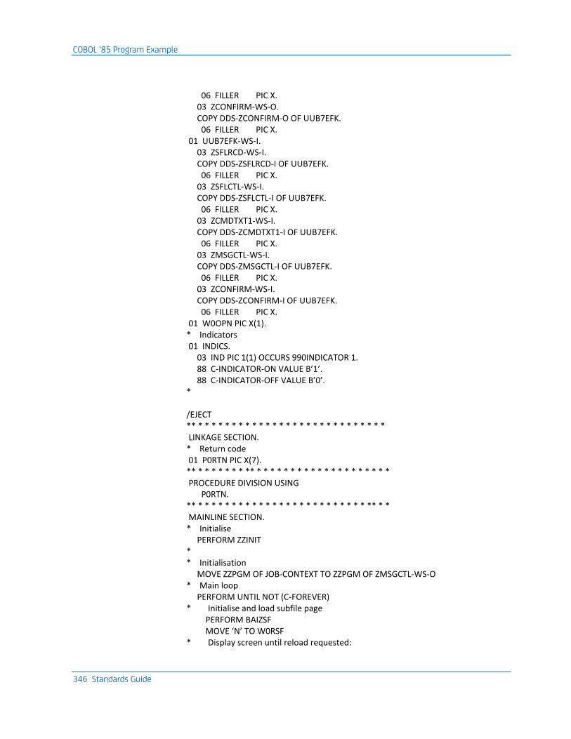
COBOL ‘85 Program Example
346 Standards Guide
06 FILLER PIC X. 03 ZCONFIRM-WS-O. COPY DDS-ZCONFIRM-O OF UUB7EFK. 06 FILLER PIC X. 01 UUB7EFK-WS-I. 03 ZSFLRCD-WS-I. COPY DDS-ZSFLRCD-I OF UUB7EFK. 06 FILLER PIC X. 03 ZSFLCTL-WS-I. COPY DDS-ZSFLCTL-I OF UUB7EFK. 06 FILLER PIC X. 03 ZCMDTXT1-WS-I. COPY DDS-ZCMDTXT1-I OF UUB7EFK. 06 FILLER PIC X. 03 ZMSGCTL-WS-I. COPY DDS-ZMSGCTL-I OF UUB7EFK. 06 FILLER PIC X. 03 ZCONFIRM-WS-I. COPY DDS-ZCONFIRM-I OF UUB7EFK. 06 FILLER PIC X. 01 W0OPN PIC X(1). * Indicators 01 INDICS. 03 IND PIC 1(1) OCCURS 990INDICATOR 1. 88 C-INDICATOR-ON VALUE B’1’. 88 C-INDICATOR-OFF VALUE B’0’. * /EJECT ** * * * * * * * * * * * * * * * * * * * * * * * * * * * * LINKAGE SECTION. * Return code 01 P0RTN PIC X(7). ** * * * * * * * ** * * * * * * * * * * * * * * * * * * * * PROCEDURE DIVISION USING P0RTN. ** * * * * * * * * * * * * * * * * * * * * * * * * * ** * * MAINLINE SECTION. * Initialise PERFORM ZZINIT * * Initialisation MOVE ZZPGM OF JOB-CONTEXT TO ZZPGM OF ZMSGCTL-WS-O * Main loop PERFORM UNTIL NOT (C-FOREVER) * Initialise and load subfile page PERFORM BAIZSF MOVE ‘N’ TO W0RSF * Display screen until reload requested:
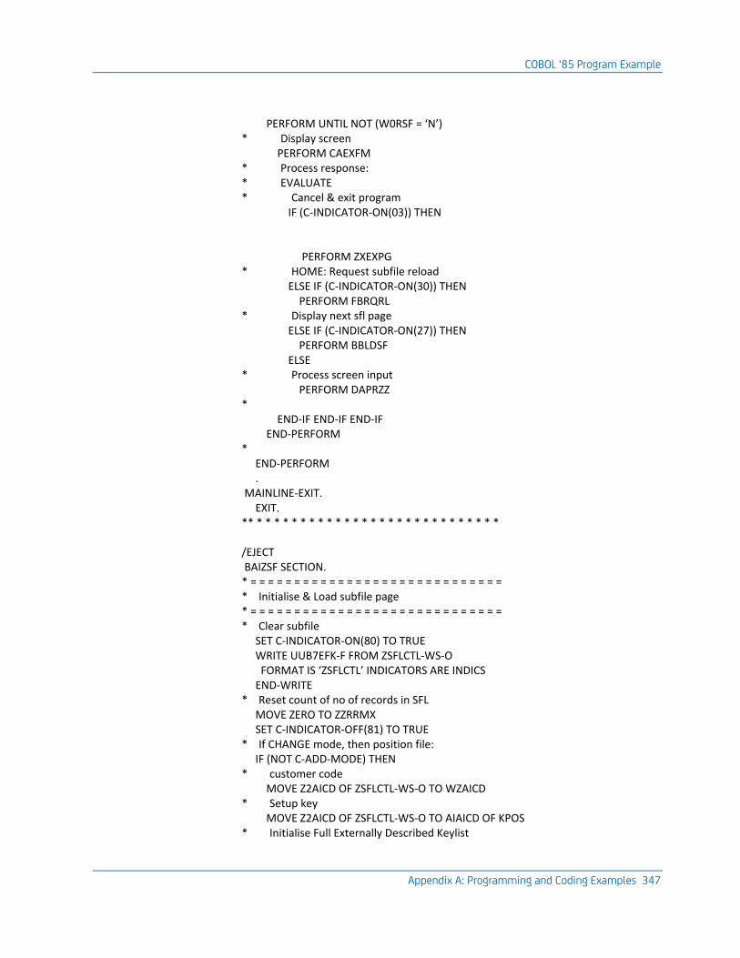
COBOL ‘85 Program Example
Appendix A: Programming and Coding Examples 347
PERFORM UNTIL NOT (W0RSF = ‘N’) * Display screen PERFORM CAEXFM * Process response: * EVALUATE * Cancel & exit program IF (C-INDICATOR-ON(03)) THEN PERFORM ZXEXPG * HOME: Request subfile reload ELSE IF (C-INDICATOR-ON(30)) THEN PERFORM FBRQRL * Display next sfl page ELSE IF (C-INDICATOR-ON(27)) THEN PERFORM BBLDSF ELSE * Process screen input PERFORM DAPRZZ * END-IF END-IF END-IF END-PERFORM * END-PERFORM . MAINLINE-EXIT. EXIT. ** * * * * * * * * * * * * * * * * * * * * * * * * * * * * /EJECT BAIZSF SECTION. * = = = = = = = = = = = = = = = = = = = = = = = = = = = = = * Initialise & Load subfile page * = = = = = = = = = = = = = = = = = = = = = = = = = = = = = * Clear subfile SET C-INDICATOR-ON(80) TO TRUE WRITE UUB7EFK-F FROM ZSFLCTL-WS-O FORMAT IS ‘ZSFLCTL’ INDICATORS ARE INDICS END-WRITE * Reset count of no of records in SFL MOVE ZERO TO ZZRRMX SET C-INDICATOR-OFF(81) TO TRUE * If CHANGE mode, then position file: IF (NOT C-ADD-MODE) THEN * customer code MOVE Z2AICD OF ZSFLCTL-WS-O TO WZAICD * Setup key MOVE Z2AICD OF ZSFLCTL-WS-O TO AIAICD OF KPOS * Initialise Full Externally Described Keylist
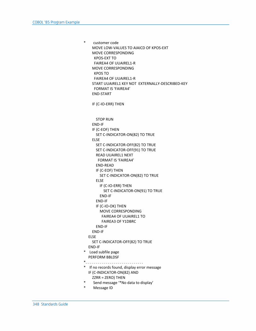
COBOL ‘85 Program Example
348 Standards Guide
* customer code MOVE LOW-VALUES TO AIAICD OF KPOS-EXT MOVE CORRESPONDING KPOS-EXT TO FAIREA4 OF UUAIREL1-R MOVE CORRESPONDING KPOS TO FAIREA4 OF UUAIREL1-R START UUAIREL1 KEY NOT EXTERNALLY-DESCRIBED-KEY FORMAT IS ‘FAIREA4’ END-START IF (C-IO-ERR) THEN STOP RUN END-IF IF (C-EOF) THEN SET C-INDICATOR-ON(82) TO TRUE ELSE SET C-INDICATOR-OFF(82) TO TRUE SET C-INDICATOR-OFF(91) TO TRUE READ UUAIREL1 NEXT FORMAT IS ‘FAIREA4’ END-READ IF (C-EOF) THEN SET C-INDICATOR-ON(82) TO TRUE ELSE IF (C-IO-ERR) THEN SET C-INDICATOR-ON(91) TO TRUE END-IF END-IF IF (C-IO-OK) THEN MOVE CORRESPONDING FAIREA4 OF UUAIREL1 TO FAIREA3 OF Y1DBRC END-IF END-IF ELSE SET C-INDICATOR-OFF(82) TO TRUE END-IF * Load subfile page PERFORM BBLDSF *. . . . . . . . . . . . . . . . . . . . . . . . . . . . . * If no records found, display error message IF (C-INDICATOR-ON(82) AND ZZRR = ZERO) THEN * Send message ‘*No data to display’ * Message ID
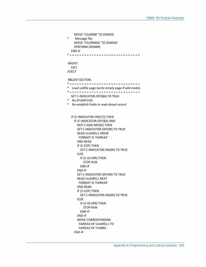
COBOL ‘85 Program Example
Appendix A: Programming and Coding Examples 349
MOVE ‘Y2U0008’ TO ZAMSID * Message file. MOVE ‘Y2USRMSG’ TO ZAMSGF PERFORM ZASNMS END-IF * = = = = = = = = = = = = = = = = = = = = = = = = = = = = = . BAEXIT. EXIT. /EJECT BBLDSF SECTION. * = = = = = = = = = = = = = = = = = = = = = = = = = = = = = * Load subfile page (write empty page if add mode). * = = = = = = = = = = = = = = = = = = = = = = = = = = = = = SET C-INDICATOR-OFF(84) TO TRUE * No SFLNXTCHG * Re-establish fields in read-ahead record IF (C-INDICATOR-ON(27)) THEN IF (C-INDICATOR-OFF(82) AND NOT C-ADD-MODE) THEN SET C-INDICATOR-OFF(90) TO TRUE READ UUAIREL1 PRIOR FORMAT IS ‘FAIREA4’ END-READ IF (C-EOF) THEN SET C-INDICATOR-ON(90) TO TRUE ELSE IF (C-IO-ERR) THEN STOP RUN END-IF END-IF SET C-INDICATOR-OFF(90) TO TRUE READ UUAIREL1 NEXT FORMAT IS ‘FAIREA4’ END-READ IF (C-EOF) THEN SET C-INDICATOR-ON(90) TO TRUE ELSE IF (C-IO-ERR) THEN STOP RUN END-IF END-IF MOVE CORRESPONDING FAIREA4 OF UUAIREL1 TO FAIREA3 OF Y1DBRC END-IF
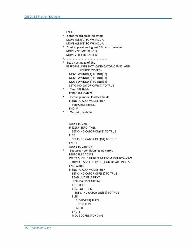
COBOL ‘85 Program Example
350 Standards Guide
END-IF * Setof record error indicators MOVE ALL B’0’ TO WKIND1-A MOVE ALL B’1’ TO WKIND1-A * Start at previous highest SFL record reached MOVE ZZRRMX TO ZZRR MOVE ZERO TO ZZRROK *. . . . . . . . . . . . . . . . . . . . . . . . . . . . . * Load next page of SFL: PERFORM UNTIL NOT (C-INDICATOR-OFF(82) AND ZZRROK ZZSFPG) MOVE WKIND0(1) TO IND(32) MOVE WKIND0(2) TO IND(33) MOVE WKIND0(3) TO IND(34) SET C-INDICATOR-OFF(87) TO TRUE * Clear SFL fields PERFORM MAIZZ1 * If change mode, load SFL fields IF (NOT C-ADD-MODE) THEN PERFORM MBFLZ1 END-IF * Output to subfile ADD 1 TO ZZRR IF (ZZRR ZERO) THEN SET C-INDICATOR-ON(81) TO TRUE ELSE SET C-INDICATOR-OFF(81) TO TRUE END-IF ADD 1 TO ZZRROK * Set screen conditioning indicators PERFORM GADSA1 WRITE SUBFILE UUB7EFK-F FROM ZSFLRCD-WS-O FORMAT IS ‘ZSFLRCD’ INDICATORS ARE INDICS END-WRITE IF (NOT C-ADD-MODE) THEN SET C-INDICATOR-OFF(82) TO TRUE READ UUAIREL1 NEXT FORMAT IS ‘FAIREA4’ END-READ IF (C-EOF) THEN SET C-INDICATOR-ON(82) TO TRUE ELSE IF (C-IO-ERR) THEN STOP RUN END-IF END-IF MOVE CORRESPONDING
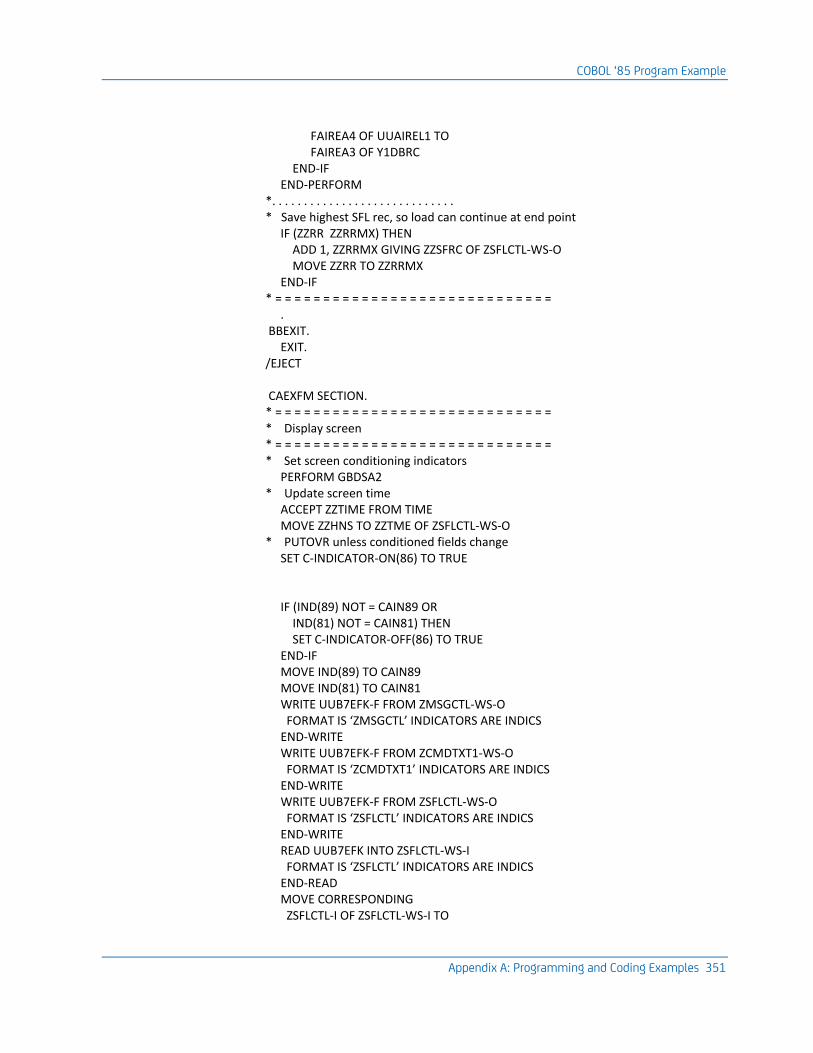
COBOL ‘85 Program Example
Appendix A: Programming and Coding Examples 351
FAIREA4 OF UUAIREL1 TO FAIREA3 OF Y1DBRC END-IF END-PERFORM *. . . . . . . . . . . . . . . . . . . . . . . . . . . . . * Save highest SFL rec, so load can continue at end point IF (ZZRR ZZRRMX) THEN ADD 1, ZZRRMX GIVING ZZSFRC OF ZSFLCTL-WS-O MOVE ZZRR TO ZZRRMX END-IF * = = = = = = = = = = = = = = = = = = = = = = = = = = = = = . BBEXIT. EXIT. /EJECT CAEXFM SECTION. * = = = = = = = = = = = = = = = = = = = = = = = = = = = = = * Display screen * = = = = = = = = = = = = = = = = = = = = = = = = = = = = = * Set screen conditioning indicators PERFORM GBDSA2 * Update screen time ACCEPT ZZTIME FROM TIME MOVE ZZHNS TO ZZTME OF ZSFLCTL-WS-O * PUTOVR unless conditioned fields change SET C-INDICATOR-ON(86) TO TRUE IF (IND(89) NOT = CAIN89 OR IND(81) NOT = CAIN81) THEN SET C-INDICATOR-OFF(86) TO TRUE END-IF MOVE IND(89) TO CAIN89 MOVE IND(81) TO CAIN81 WRITE UUB7EFK-F FROM ZMSGCTL-WS-O FORMAT IS ‘ZMSGCTL’ INDICATORS ARE INDICS END-WRITE WRITE UUB7EFK-F FROM ZCMDTXT1-WS-O FORMAT IS ‘ZCMDTXT1’ INDICATORS ARE INDICS END-WRITE WRITE UUB7EFK-F FROM ZSFLCTL-WS-O FORMAT IS ‘ZSFLCTL’ INDICATORS ARE INDICS END-WRITE READ UUB7EFK INTO ZSFLCTL-WS-I FORMAT IS ‘ZSFLCTL’ INDICATORS ARE INDICS END-READ MOVE CORRESPONDING ZSFLCTL-I OF ZSFLCTL-WS-I TO
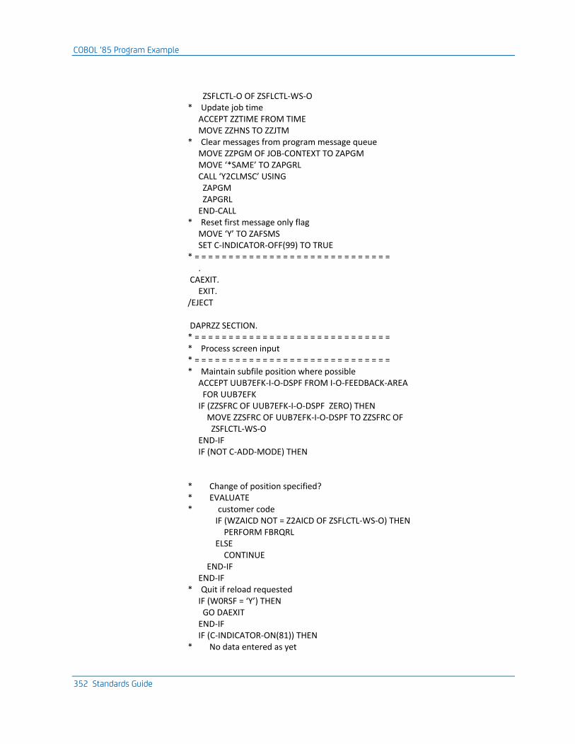
COBOL ‘85 Program Example
352 Standards Guide
ZSFLCTL-O OF ZSFLCTL-WS-O * Update job time ACCEPT ZZTIME FROM TIME MOVE ZZHNS TO ZZJTM * Clear messages from program message queue MOVE ZZPGM OF JOB-CONTEXT TO ZAPGM MOVE ‘*SAME’ TO ZAPGRL CALL ‘Y2CLMSC’ USING ZAPGM ZAPGRL END-CALL * Reset first message only flag MOVE ‘Y’ TO ZAFSMS SET C-INDICATOR-OFF(99) TO TRUE * = = = = = = = = = = = = = = = = = = = = = = = = = = = = = . CAEXIT. EXIT. /EJECT DAPRZZ SECTION. * = = = = = = = = = = = = = = = = = = = = = = = = = = = = = * Process screen input * = = = = = = = = = = = = = = = = = = = = = = = = = = = = = * Maintain subfile position where possible ACCEPT UUB7EFK-I-O-DSPF FROM I-O-FEEDBACK-AREA FOR UUB7EFK IF (ZZSFRC OF UUB7EFK-I-O-DSPF ZERO) THEN MOVE ZZSFRC OF UUB7EFK-I-O-DSPF TO ZZSFRC OF ZSFLCTL-WS-O END-IF IF (NOT C-ADD-MODE) THEN * Change of position specified? * EVALUATE * customer code IF (WZAICD NOT = Z2AICD OF ZSFLCTL-WS-O) THEN PERFORM FBRQRL ELSE CONTINUE END-IF END-IF * Quit if reload requested IF (W0RSF = ‘Y’) THEN GO DAEXIT END-IF IF (C-INDICATOR-ON(81)) THEN * No data entered as yet
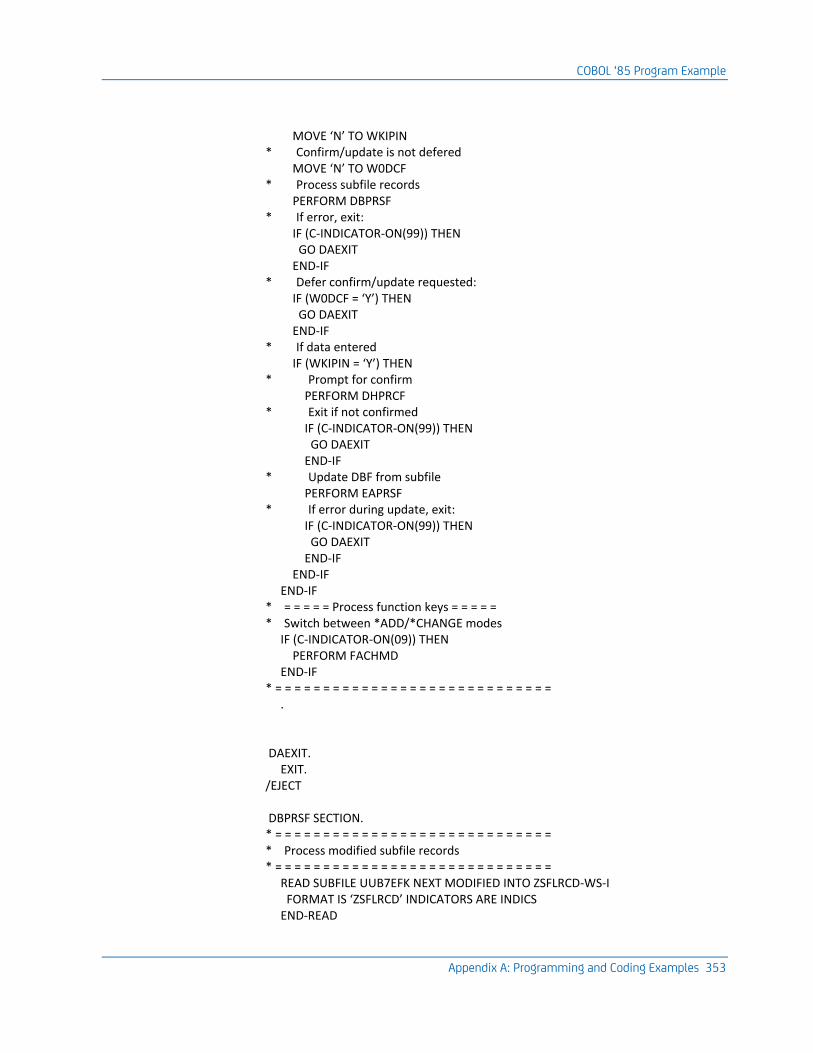
COBOL ‘85 Program Example
Appendix A: Programming and Coding Examples 353
MOVE ‘N’ TO WKIPIN * Confirm/update is not defered MOVE ‘N’ TO W0DCF * Process subfile records PERFORM DBPRSF * If error, exit: IF (C-INDICATOR-ON(99)) THEN GO DAEXIT END-IF * Defer confirm/update requested: IF (W0DCF = ‘Y’) THEN GO DAEXIT END-IF * If data entered IF (WKIPIN = ‘Y’) THEN * Prompt for confirm PERFORM DHPRCF * Exit if not confirmed IF (C-INDICATOR-ON(99)) THEN GO DAEXIT END-IF * Update DBF from subfile PERFORM EAPRSF * If error during update, exit: IF (C-INDICATOR-ON(99)) THEN GO DAEXIT END-IF END-IF END-IF * = = = = = Process function keys = = = = = * Switch between *ADD/*CHANGE modes IF (C-INDICATOR-ON(09)) THEN PERFORM FACHMD END-IF * = = = = = = = = = = = = = = = = = = = = = = = = = = = = = . DAEXIT. EXIT. /EJECT DBPRSF SECTION. * = = = = = = = = = = = = = = = = = = = = = = = = = = = = = * Process modified subfile records * = = = = = = = = = = = = = = = = = = = = = = = = = = = = = READ SUBFILE UUB7EFK NEXT MODIFIED INTO ZSFLRCD-WS-I FORMAT IS ‘ZSFLRCD’ INDICATORS ARE INDICS END-READ
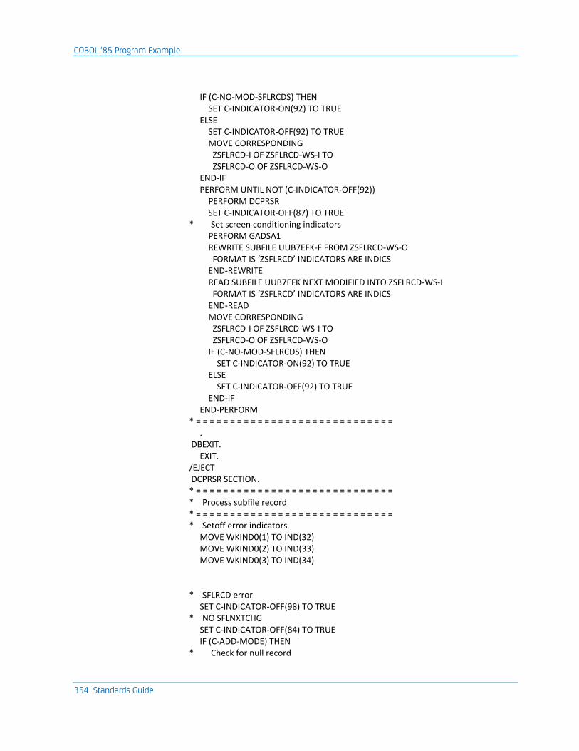
COBOL ‘85 Program Example
354 Standards Guide
IF (C-NO-MOD-SFLRCDS) THEN SET C-INDICATOR-ON(92) TO TRUE ELSE SET C-INDICATOR-OFF(92) TO TRUE MOVE CORRESPONDING ZSFLRCD-I OF ZSFLRCD-WS-I TO ZSFLRCD-O OF ZSFLRCD-WS-O END-IF PERFORM UNTIL NOT (C-INDICATOR-OFF(92)) PERFORM DCPRSR SET C-INDICATOR-OFF(87) TO TRUE * Set screen conditioning indicators PERFORM GADSA1 REWRITE SUBFILE UUB7EFK-F FROM ZSFLRCD-WS-O FORMAT IS ‘ZSFLRCD’ INDICATORS ARE INDICS END-REWRITE READ SUBFILE UUB7EFK NEXT MODIFIED INTO ZSFLRCD-WS-I FORMAT IS ‘ZSFLRCD’ INDICATORS ARE INDICS END-READ MOVE CORRESPONDING ZSFLRCD-I OF ZSFLRCD-WS-I TO ZSFLRCD-O OF ZSFLRCD-WS-O IF (C-NO-MOD-SFLRCDS) THEN SET C-INDICATOR-ON(92) TO TRUE ELSE SET C-INDICATOR-OFF(92) TO TRUE END-IF END-PERFORM * = = = = = = = = = = = = = = = = = = = = = = = = = = = = = . DBEXIT. EXIT. /EJECT DCPRSR SECTION. * = = = = = = = = = = = = = = = = = = = = = = = = = = = = = * Process subfile record * = = = = = = = = = = = = = = = = = = = = = = = = = = = = = * Setoff error indicators MOVE WKIND0(1) TO IND(32) MOVE WKIND0(2) TO IND(33) MOVE WKIND0(3) TO IND(34) * SFLRCD error SET C-INDICATOR-OFF(98) TO TRUE * NO SFLNXTCHG SET C-INDICATOR-OFF(84) TO TRUE IF (C-ADD-MODE) THEN * Check for null record
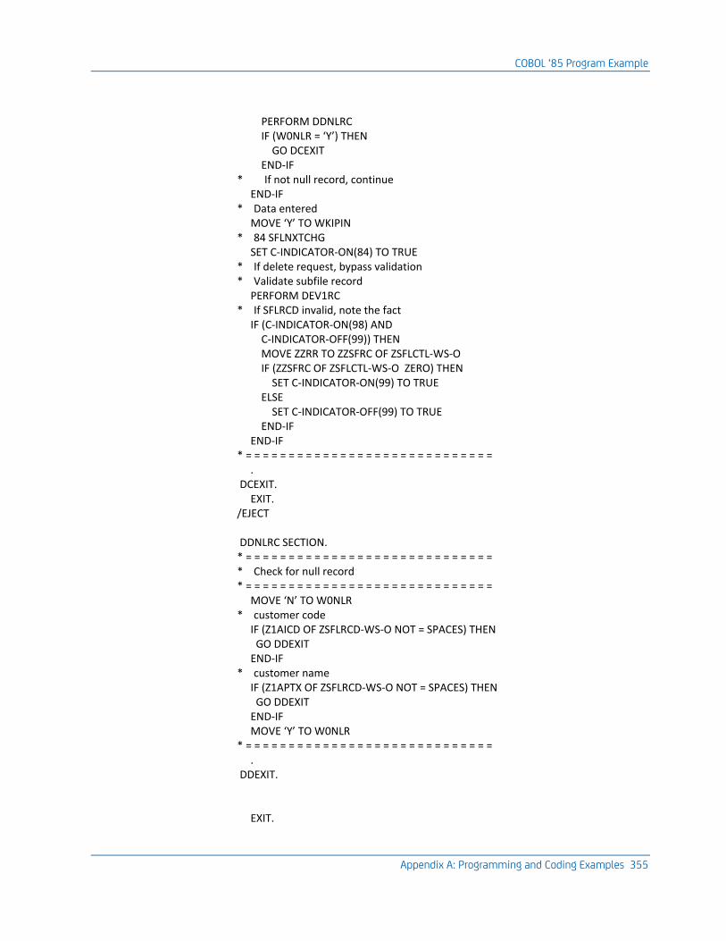
COBOL ‘85 Program Example
Appendix A: Programming and Coding Examples 355
PERFORM DDNLRC IF (W0NLR = ‘Y’) THEN GO DCEXIT END-IF * If not null record, continue END-IF * Data entered MOVE ‘Y’ TO WKIPIN * 84 SFLNXTCHG SET C-INDICATOR-ON(84) TO TRUE * If delete request, bypass validation * Validate subfile record PERFORM DEV1RC * If SFLRCD invalid, note the fact IF (C-INDICATOR-ON(98) AND C-INDICATOR-OFF(99)) THEN MOVE ZZRR TO ZZSFRC OF ZSFLCTL-WS-O IF (ZZSFRC OF ZSFLCTL-WS-O ZERO) THEN SET C-INDICATOR-ON(99) TO TRUE ELSE SET C-INDICATOR-OFF(99) TO TRUE END-IF END-IF * = = = = = = = = = = = = = = = = = = = = = = = = = = = = = . DCEXIT. EXIT. /EJECT DDNLRC SECTION. * = = = = = = = = = = = = = = = = = = = = = = = = = = = = = * Check for null record * = = = = = = = = = = = = = = = = = = = = = = = = = = = = = MOVE ‘N’ TO W0NLR * customer code IF (Z1AICD OF ZSFLRCD-WS-O NOT = SPACES) THEN GO DDEXIT END-IF * customer name IF (Z1APTX OF ZSFLRCD-WS-O NOT = SPACES) THEN GO DDEXIT END-IF MOVE ‘Y’ TO W0NLR * = = = = = = = = = = = = = = = = = = = = = = = = = = = = = . DDEXIT. EXIT.
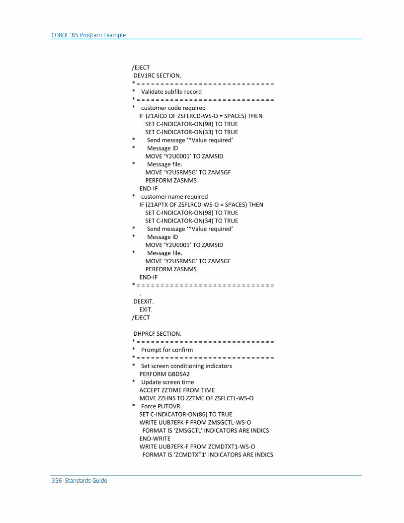
COBOL ‘85 Program Example
356 Standards Guide
/EJECT DEV1RC SECTION. * = = = = = = = = = = = = = = = = = = = = = = = = = = = = = * Validate subfile record * = = = = = = = = = = = = = = = = = = = = = = = = = = = = = * customer code required IF (Z1AICD OF ZSFLRCD-WS-O = SPACES) THEN SET C-INDICATOR-ON(98) TO TRUE SET C-INDICATOR-ON(33) TO TRUE * Send message ‘*Value required’ * Message ID MOVE ‘Y2U0001’ TO ZAMSID * Message file. MOVE ‘Y2USRMSG’ TO ZAMSGF PERFORM ZASNMS END-IF * customer name required IF (Z1APTX OF ZSFLRCD-WS-O = SPACES) THEN SET C-INDICATOR-ON(98) TO TRUE SET C-INDICATOR-ON(34) TO TRUE * Send message ‘*Value required’ * Message ID MOVE ‘Y2U0001’ TO ZAMSID * Message file. MOVE ‘Y2USRMSG’ TO ZAMSGF PERFORM ZASNMS END-IF * = = = = = = = = = = = = = = = = = = = = = = = = = = = = = . DEEXIT. EXIT. /EJECT DHPRCF SECTION. * = = = = = = = = = = = = = = = = = = = = = = = = = = = = = * Prompt for confirm * = = = = = = = = = = = = = = = = = = = = = = = = = = = = = * Set screen conditioning indicators PERFORM GBDSA2 * Update screen time ACCEPT ZZTIME FROM TIME MOVE ZZHNS TO ZZTME OF ZSFLCTL-WS-O * Force PUTOVR SET C-INDICATOR-ON(86) TO TRUE WRITE UUB7EFK-F FROM ZMSGCTL-WS-O FORMAT IS ‘ZMSGCTL’ INDICATORS ARE INDICS END-WRITE WRITE UUB7EFK-F FROM ZCMDTXT1-WS-O FORMAT IS ‘ZCMDTXT1’ INDICATORS ARE INDICS
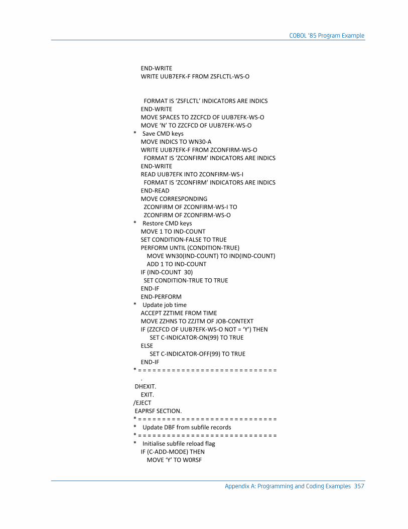
COBOL ‘85 Program Example
Appendix A: Programming and Coding Examples 357
END-WRITE WRITE UUB7EFK-F FROM ZSFLCTL-WS-O FORMAT IS ‘ZSFLCTL’ INDICATORS ARE INDICS END-WRITE MOVE SPACES TO ZZCFCD OF UUB7EFK-WS-O MOVE ‘N’ TO ZZCFCD OF UUB7EFK-WS-O * Save CMD keys MOVE INDICS TO WN30-A WRITE UUB7EFK-F FROM ZCONFIRM-WS-O FORMAT IS ‘ZCONFIRM’ INDICATORS ARE INDICS END-WRITE READ UUB7EFK INTO ZCONFIRM-WS-I FORMAT IS ‘ZCONFIRM’ INDICATORS ARE INDICS END-READ MOVE CORRESPONDING ZCONFIRM OF ZCONFIRM-WS-I TO ZCONFIRM OF ZCONFIRM-WS-O * Restore CMD keys MOVE 1 TO IND-COUNT SET CONDITION-FALSE TO TRUE PERFORM UNTIL (CONDITION-TRUE) MOVE WN30(IND-COUNT) TO IND(IND-COUNT) ADD 1 TO IND-COUNT IF (IND-COUNT 30) SET CONDITION-TRUE TO TRUE END-IF END-PERFORM * Update job time ACCEPT ZZTIME FROM TIME MOVE ZZHNS TO ZZJTM OF JOB-CONTEXT IF (ZZCFCD OF UUB7EFK-WS-O NOT = ‘Y’) THEN SET C-INDICATOR-ON(99) TO TRUE ELSE SET C-INDICATOR-OFF(99) TO TRUE END-IF * = = = = = = = = = = = = = = = = = = = = = = = = = = = = = . DHEXIT. EXIT. /EJECT EAPRSF SECTION. * = = = = = = = = = = = = = = = = = = = = = = = = = = = = = * Update DBF from subfile records * = = = = = = = = = = = = = = = = = = = = = = = = = = = = = * Initialise subfile reload flag IF (C-ADD-MODE) THEN MOVE ‘Y’ TO W0RSF
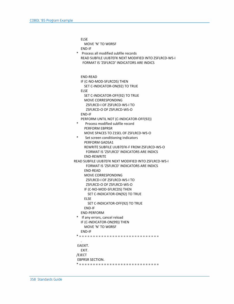
COBOL ‘85 Program Example
358 Standards Guide
ELSE MOVE ‘N’ TO W0RSF END-IF * Process all modified subfile records READ SUBFILE UUB7EFK NEXT MODIFIED INTO ZSFLRCD-WS-I FORMAT IS ‘ZSFLRCD’ INDICATORS ARE INDICS END-READ IF (C-NO-MOD-SFLRCDS) THEN SET C-INDICATOR-ON(92) TO TRUE ELSE SET C-INDICATOR-OFF(92) TO TRUE MOVE CORRESPONDING ZSFLRCD-I OF ZSFLRCD-WS-I TO ZSFLRCD-O OF ZSFLRCD-WS-O END-IF PERFORM UNTIL NOT (C-INDICATOR-OFF(92)) * Process modified subfile record PERFORM EBPRSR MOVE SPACES TO Z1SEL OF ZSFLRCD-WS-O * Set screen conditioning indicators PERFORM GADSA1 REWRITE SUBFILE UUB7EFK-F FROM ZSFLRCD-WS-O FORMAT IS ‘ZSFLRCD’ INDICATORS ARE INDICS END-REWRITE READ SUBFILE UUB7EFK NEXT MODIFIED INTO ZSFLRCD-WS-I FORMAT IS ‘ZSFLRCD’ INDICATORS ARE INDICS END-READ MOVE CORRESPONDING ZSFLRCD-I OF ZSFLRCD-WS-I TO ZSFLRCD-O OF ZSFLRCD-WS-O IF (C-NO-MOD-SFLRCDS) THEN SET C-INDICATOR-ON(92) TO TRUE ELSE SET C-INDICATOR-OFF(92) TO TRUE END-IF END-PERFORM * If any errors, cancel reload IF (C-INDICATOR-ON(99)) THEN MOVE ‘N’ TO W0RSF END-IF * = = = = = = = = = = = = = = = = = = = = = = = = = = = = = . EAEXIT. EXIT. /EJECT EBPRSR SECTION. * = = = = = = = = = = = = = = = = = = = = = = = = = = = = =
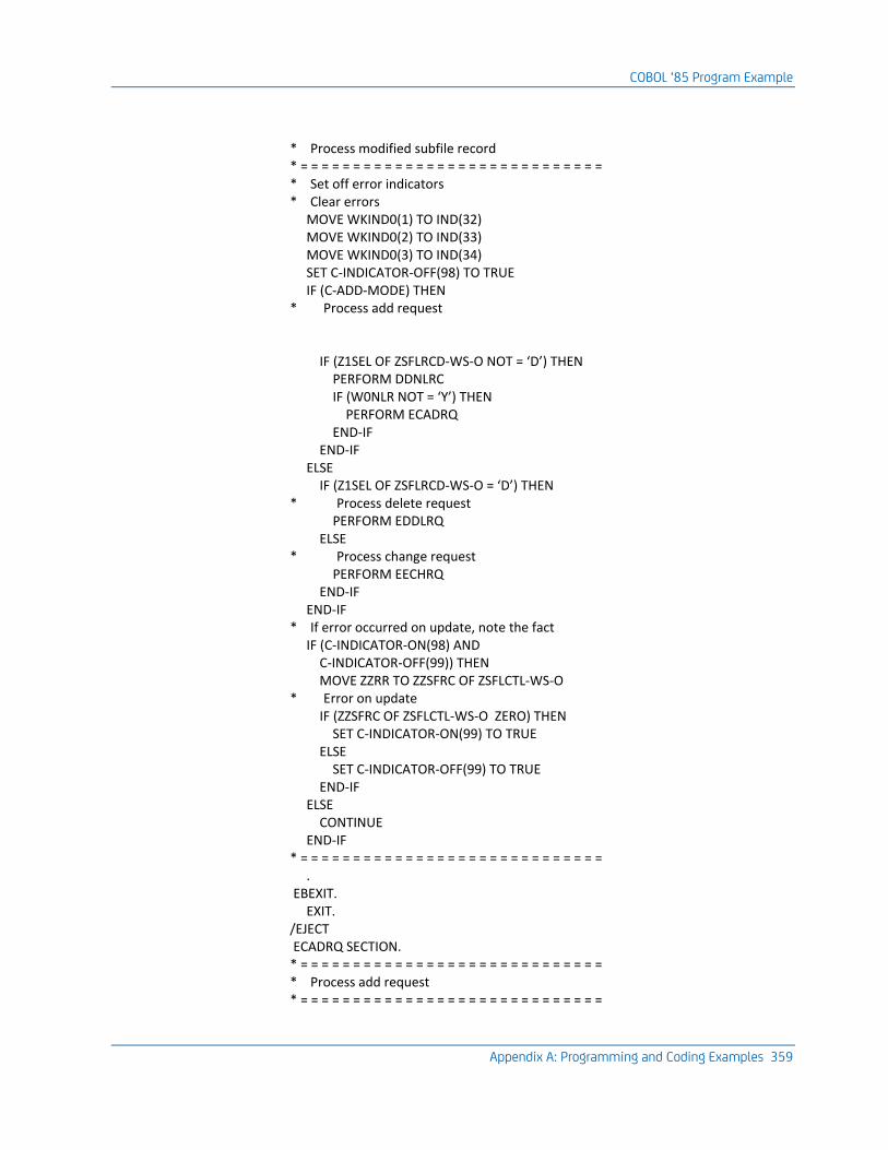
COBOL ‘85 Program Example
Appendix A: Programming and Coding Examples 359
* Process modified subfile record * = = = = = = = = = = = = = = = = = = = = = = = = = = = = = * Set off error indicators * Clear errors MOVE WKIND0(1) TO IND(32) MOVE WKIND0(2) TO IND(33) MOVE WKIND0(3) TO IND(34) SET C-INDICATOR-OFF(98) TO TRUE IF (C-ADD-MODE) THEN * Process add request IF (Z1SEL OF ZSFLRCD-WS-O NOT = ‘D’) THEN PERFORM DDNLRC IF (W0NLR NOT = ‘Y’) THEN PERFORM ECADRQ END-IF END-IF ELSE IF (Z1SEL OF ZSFLRCD-WS-O = ‘D’) THEN * Process delete request PERFORM EDDLRQ ELSE * Process change request PERFORM EECHRQ END-IF END-IF * If error occurred on update, note the fact IF (C-INDICATOR-ON(98) AND C-INDICATOR-OFF(99)) THEN MOVE ZZRR TO ZZSFRC OF ZSFLCTL-WS-O * Error on update IF (ZZSFRC OF ZSFLCTL-WS-O ZERO) THEN SET C-INDICATOR-ON(99) TO TRUE ELSE SET C-INDICATOR-OFF(99) TO TRUE END-IF ELSE CONTINUE END-IF * = = = = = = = = = = = = = = = = = = = = = = = = = = = = = . EBEXIT. EXIT. /EJECT ECADRQ SECTION. * = = = = = = = = = = = = = = = = = = = = = = = = = = = = = * Process add request * = = = = = = = = = = = = = = = = = = = = = = = = = = = = =
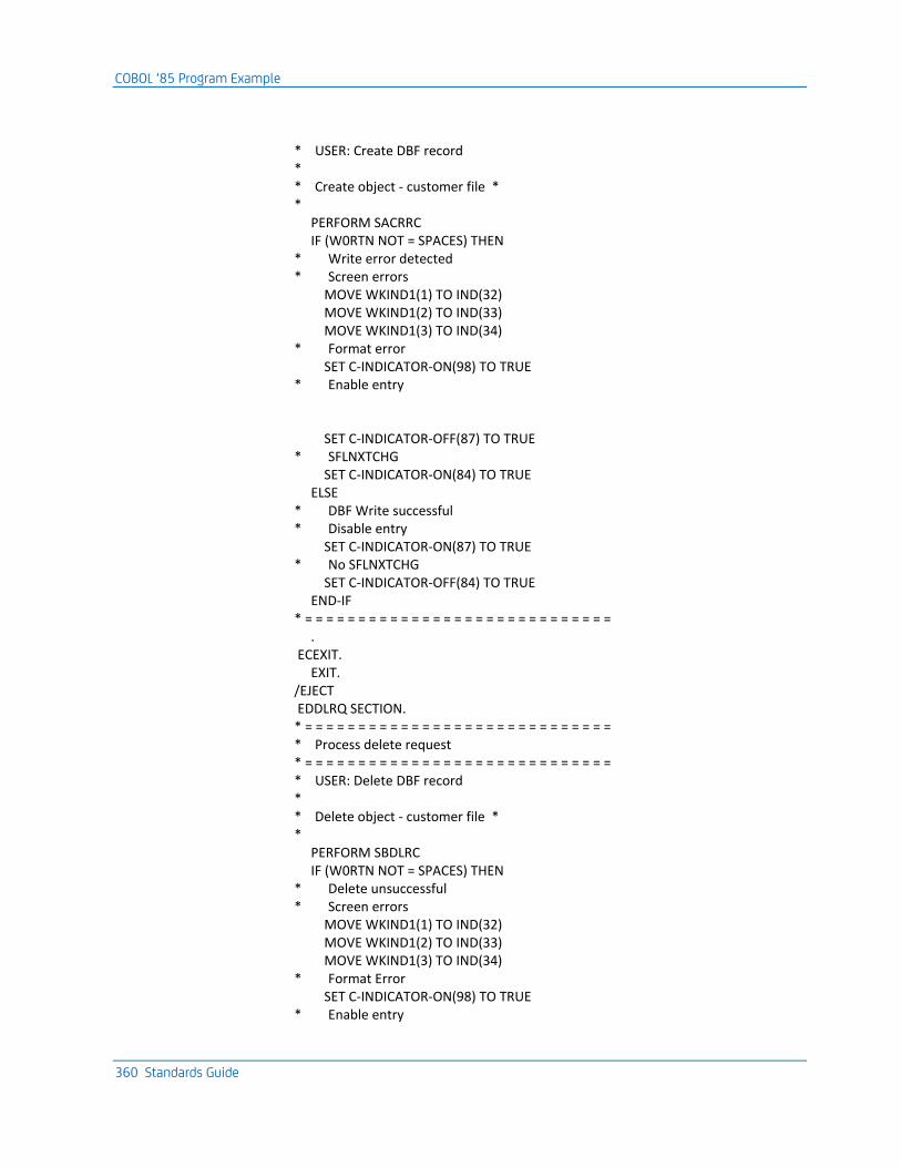
COBOL ‘85 Program Example
360 Standards Guide
* USER: Create DBF record * * Create object - customer file * * PERFORM SACRRC IF (W0RTN NOT = SPACES) THEN * Write error detected * Screen errors MOVE WKIND1(1) TO IND(32) MOVE WKIND1(2) TO IND(33) MOVE WKIND1(3) TO IND(34) * Format error SET C-INDICATOR-ON(98) TO TRUE * Enable entry SET C-INDICATOR-OFF(87) TO TRUE * SFLNXTCHG SET C-INDICATOR-ON(84) TO TRUE ELSE * DBF Write successful * Disable entry SET C-INDICATOR-ON(87) TO TRUE * No SFLNXTCHG SET C-INDICATOR-OFF(84) TO TRUE END-IF * = = = = = = = = = = = = = = = = = = = = = = = = = = = = = . ECEXIT. EXIT. /EJECT EDDLRQ SECTION. * = = = = = = = = = = = = = = = = = = = = = = = = = = = = = * Process delete request * = = = = = = = = = = = = = = = = = = = = = = = = = = = = = * USER: Delete DBF record * * Delete object - customer file * * PERFORM SBDLRC IF (W0RTN NOT = SPACES) THEN * Delete unsuccessful * Screen errors MOVE WKIND1(1) TO IND(32) MOVE WKIND1(2) TO IND(33) MOVE WKIND1(3) TO IND(34) * Format Error SET C-INDICATOR-ON(98) TO TRUE * Enable entry
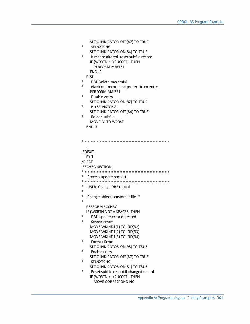
COBOL ‘85 Program Example
Appendix A: Programming and Coding Examples 361
SET C-INDICATOR-OFF(87) TO TRUE * SFLNXTCHG SET C-INDICATOR-ON(84) TO TRUE * If record altered, reset subfile record IF (W0RTN = ‘Y2U0007’) THEN PERFORM MBFLZ1 END-IF ELSE * DBF Delete successful * Blank out record and protect from entry PERFORM MAIZZ1 * Disable entry SET C-INDICATOR-ON(87) TO TRUE * No SFLNXTCHG SET C-INDICATOR-OFF(84) TO TRUE * Reload subfile MOVE ‘Y’ TO W0RSF END-IF * = = = = = = = = = = = = = = = = = = = = = = = = = = = = = . EDEXIT. EXIT. /EJECT EECHRQ SECTION. * = = = = = = = = = = = = = = = = = = = = = = = = = = = = = * Process update request * = = = = = = = = = = = = = = = = = = = = = = = = = = = = = * USER: Change DBF record * * Change object - customer file * * PERFORM SCCHRC IF (W0RTN NOT = SPACES) THEN * DBF Update error detected * Screen errors MOVE WKIND1(1) TO IND(32) MOVE WKIND1(2) TO IND(33) MOVE WKIND1(3) TO IND(34) * Format Error SET C-INDICATOR-ON(98) TO TRUE * Enable entry SET C-INDICATOR-OFF(87) TO TRUE * SFLNXTCHG SET C-INDICATOR-ON(84) TO TRUE * Reset subfile record if changed record IF (W0RTN = ‘Y2U0007’) THEN MOVE CORRESPONDING
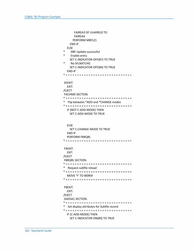
COBOL ‘85 Program Example
362 Standards Guide
FAIREA3 OF UUAIREL0 TO FAIREA4 PERFORM MBFLZ1 END-IF ELSE * DBF Update successful * Enable entry SET C-INDICATOR-OFF(87) TO TRUE * No SFLNXTCHG SET C-INDICATOR-OFF(84) TO TRUE END-IF * = = = = = = = = = = = = = = = = = = = = = = = = = = = = = . EEEXIT. EXIT. /EJECT FACHMD SECTION. * = = = = = = = = = = = = = = = = = = = = = = = = = = = = = * Flip between *ADD and *CHANGE modes * = = = = = = = = = = = = = = = = = = = = = = = = = = = = = IF (NOT C-ADD-MODE) THEN SET C-ADD-MODE TO TRUE ELSE SET C-CHANGE-MODE TO TRUE END-IF PERFORM FBRQRL * = = = = = = = = = = = = = = = = = = = = = = = = = = = = = . FAEXIT. EXIT. /EJECT FBRQRL SECTION. * = = = = = = = = = = = = = = = = = = = = = = = = = = = = = * Request subfile reload * = = = = = = = = = = = = = = = = = = = = = = = = = = = = = MOVE ‘Y’ TO W0RSF * = = = = = = = = = = = = = = = = = = = = = = = = = = = = = . FBEXIT. EXIT. /EJECT GADSA1 SECTION. * = = = = = = = = = = = = = = = = = = = = = = = = = = = = = * Set display attributes for Subfile record * = = = = = = = = = = = = = = = = = = = = = = = = = = = = = IF (C-ADD-MODE) THEN SET C-INDICATOR-ON(89) TO TRUE
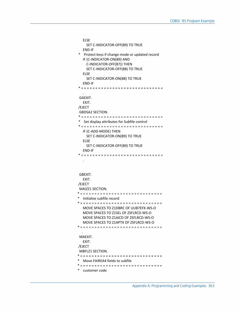
COBOL ‘85 Program Example
Appendix A: Programming and Coding Examples 363
ELSE SET C-INDICATOR-OFF(89) TO TRUE END-IF * Protect keys if change mode or updated record IF (C-INDICATOR-ON(89) AND C-INDICATOR-OFF(87)) THEN SET C-INDICATOR-OFF(88) TO TRUE ELSE SET C-INDICATOR-ON(88) TO TRUE END-IF * = = = = = = = = = = = = = = = = = = = = = = = = = = = = = . GAEXIT. EXIT. /EJECT GBDSA2 SECTION. * = = = = = = = = = = = = = = = = = = = = = = = = = = = = = * Set display attributes for Subfile control * = = = = = = = = = = = = = = = = = = = = = = = = = = = = = IF (C-ADD-MODE) THEN SET C-INDICATOR-ON(89) TO TRUE ELSE SET C-INDICATOR-OFF(89) TO TRUE END-IF * = = = = = = = = = = = = = = = = = = = = = = = = = = = = = . GBEXIT. EXIT. /EJECT MAIZZ1 SECTION. * = = = = = = = = = = = = = = = = = = = = = = = = = = = = = * Initialise subfile record * = = = = = = = = = = = = = = = = = = = = = = = = = = = = = MOVE SPACES TO Z1DBRC OF UUB7EFK-WS-O MOVE SPACES TO Z1SEL OF ZSFLRCD-WS-O MOVE SPACES TO Z1AICD OF ZSFLRCD-WS-O MOVE SPACES TO Z1APTX OF ZSFLRCD-WS-O * = = = = = = = = = = = = = = = = = = = = = = = = = = = = = . MAEXIT. EXIT. /EJECT MBFLZ1 SECTION. * = = = = = = = = = = = = = = = = = = = = = = = = = = = = = * Move FAIREA4 fields to subfile * = = = = = = = = = = = = = = = = = = = = = = = = = = = = = * customer code
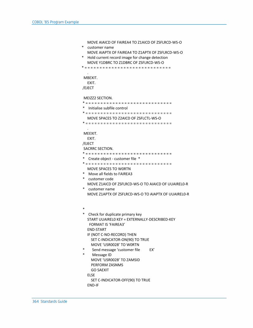
COBOL ‘85 Program Example
364 Standards Guide
MOVE AIAICD OF FAIREA4 TO Z1AICD OF ZSFLRCD-WS-O * customer name MOVE AIAPTX OF FAIREA4 TO Z1APTX OF ZSFLRCD-WS-O * Hold current record image for change detection MOVE Y1DBRC TO Z1DBRC OF ZSFLRCD-WS-O * = = = = = = = = = = = = = = = = = = = = = = = = = = = = = . MBEXIT. EXIT. /EJECT MEIZZ2 SECTION. * = = = = = = = = = = = = = = = = = = = = = = = = = = = = = * Initialise subfile control * = = = = = = = = = = = = = = = = = = = = = = = = = = = = = MOVE SPACES TO Z2AICD OF ZSFLCTL-WS-O * = = = = = = = = = = = = = = = = = = = = = = = = = = = = = . MEEXIT. EXIT. /EJECT SACRRC SECTION. * = = = = = = = = = = = = = = = = = = = = = = = = = = = = = * Create object - customer file * * = = = = = = = = = = = = = = = = = = = = = = = = = = = = = MOVE SPACES TO W0RTN * Move all fields to FAIREA3 * customer code MOVE Z1AICD OF ZSFLRCD-WS-O TO AIAICD OF UUAIREL0-R * customer name MOVE Z1APTX OF ZSFLRCD-WS-O TO AIAPTX OF UUAIREL0-R * * Check for duplicate primary key START UUAIREL0 KEY = EXTERNALLY-DESCRIBED-KEY FORMAT IS ‘FAIREA3’ END-START IF (NOT C-NO-RECORD) THEN SET C-INDICATOR-ON(90) TO TRUE MOVE ‘USR0028’ TO W0RTN * Send message ‘customer file EX’ * Message ID MOVE ‘USR0028’ TO ZAMSID PERFORM ZASNMS GO SAEXIT ELSE SET C-INDICATOR-OFF(90) TO TRUE END-IF
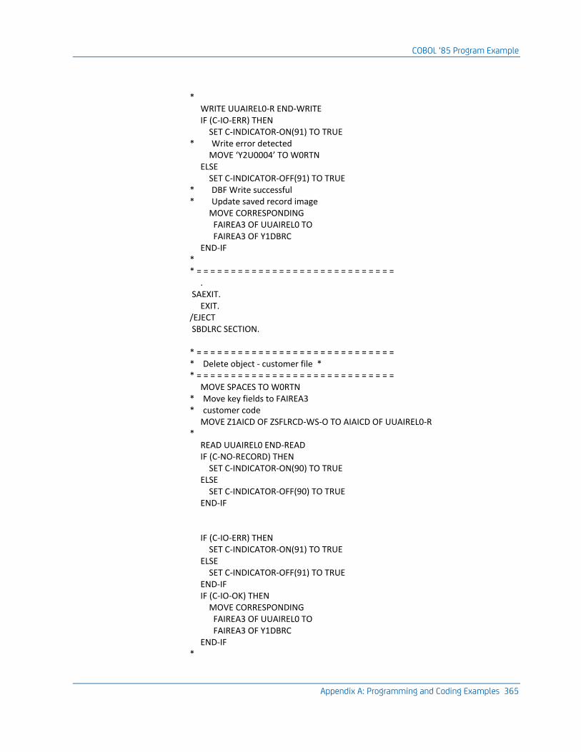
COBOL ‘85 Program Example
Appendix A: Programming and Coding Examples 365
* WRITE UUAIREL0-R END-WRITE IF (C-IO-ERR) THEN SET C-INDICATOR-ON(91) TO TRUE * Write error detected MOVE ‘Y2U0004’ TO W0RTN ELSE SET C-INDICATOR-OFF(91) TO TRUE * DBF Write successful * Update saved record image MOVE CORRESPONDING FAIREA3 OF UUAIREL0 TO FAIREA3 OF Y1DBRC END-IF * * = = = = = = = = = = = = = = = = = = = = = = = = = = = = = . SAEXIT. EXIT. /EJECT SBDLRC SECTION. * = = = = = = = = = = = = = = = = = = = = = = = = = = = = = * Delete object - customer file * * = = = = = = = = = = = = = = = = = = = = = = = = = = = = = MOVE SPACES TO W0RTN * Move key fields to FAIREA3 * customer code MOVE Z1AICD OF ZSFLRCD-WS-O TO AIAICD OF UUAIREL0-R * READ UUAIREL0 END-READ IF (C-NO-RECORD) THEN SET C-INDICATOR-ON(90) TO TRUE ELSE SET C-INDICATOR-OFF(90) TO TRUE END-IF IF (C-IO-ERR) THEN SET C-INDICATOR-ON(91) TO TRUE ELSE SET C-INDICATOR-OFF(91) TO TRUE END-IF IF (C-IO-OK) THEN MOVE CORRESPONDING FAIREA3 OF UUAIREL0 TO FAIREA3 OF Y1DBRC END-IF *
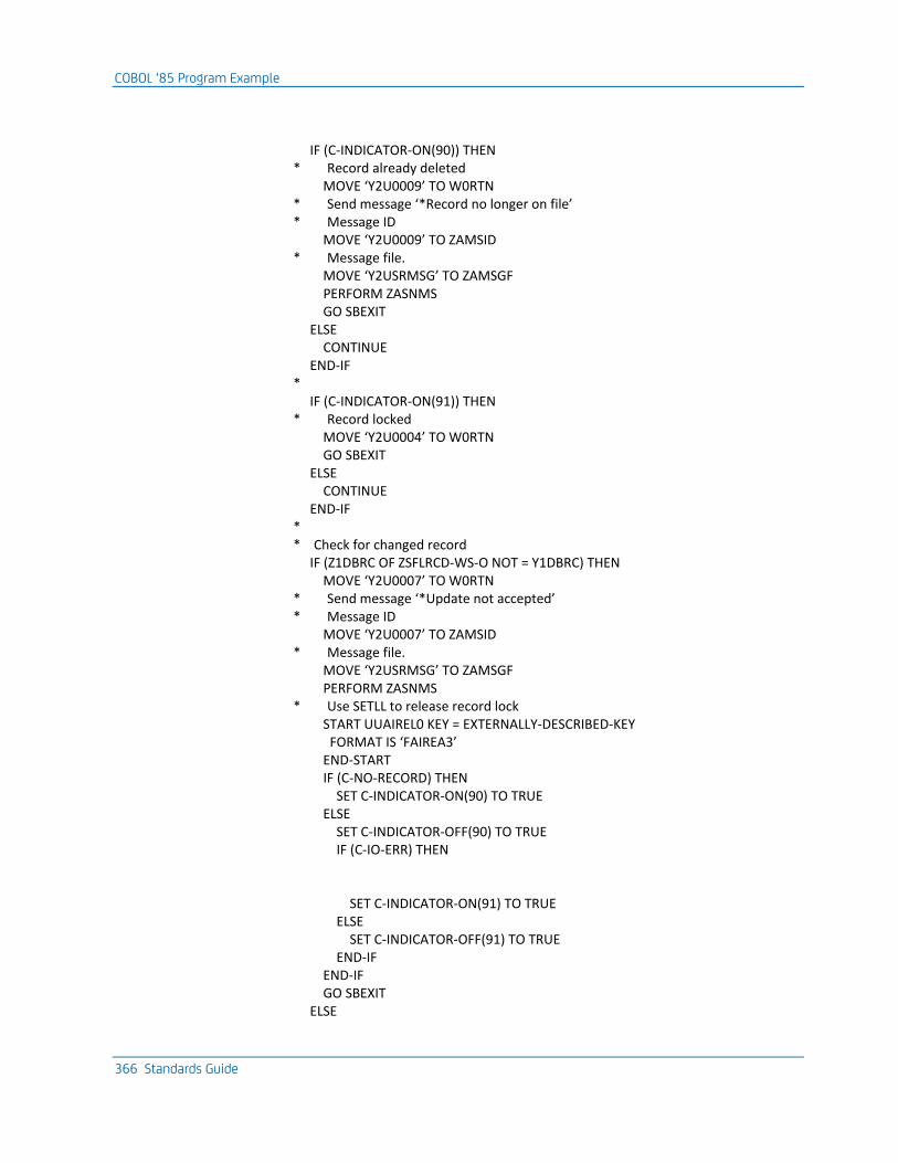
COBOL ‘85 Program Example
366 Standards Guide
IF (C-INDICATOR-ON(90)) THEN * Record already deleted MOVE ‘Y2U0009’ TO W0RTN * Send message ‘*Record no longer on file’ * Message ID MOVE ‘Y2U0009’ TO ZAMSID * Message file. MOVE ‘Y2USRMSG’ TO ZAMSGF PERFORM ZASNMS GO SBEXIT ELSE CONTINUE END-IF * IF (C-INDICATOR-ON(91)) THEN * Record locked MOVE ‘Y2U0004’ TO W0RTN GO SBEXIT ELSE CONTINUE END-IF * * Check for changed record IF (Z1DBRC OF ZSFLRCD-WS-O NOT = Y1DBRC) THEN MOVE ‘Y2U0007’ TO W0RTN * Send message ‘*Update not accepted’ * Message ID MOVE ‘Y2U0007’ TO ZAMSID * Message file. MOVE ‘Y2USRMSG’ TO ZAMSGF PERFORM ZASNMS * Use SETLL to release record lock START UUAIREL0 KEY = EXTERNALLY-DESCRIBED-KEY FORMAT IS ‘FAIREA3’ END-START IF (C-NO-RECORD) THEN SET C-INDICATOR-ON(90) TO TRUE ELSE SET C-INDICATOR-OFF(90) TO TRUE IF (C-IO-ERR) THEN SET C-INDICATOR-ON(91) TO TRUE ELSE SET C-INDICATOR-OFF(91) TO TRUE END-IF END-IF GO SBEXIT ELSE
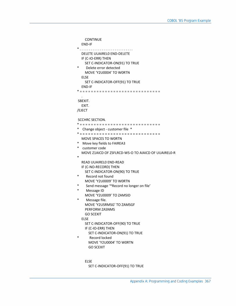
COBOL ‘85 Program Example
Appendix A: Programming and Coding Examples 367
CONTINUE END-IF * . . . . . . . . . . . . . . . . . . . . . . . . . . . . . DELETE UUAIREL0 END-DELETE IF (C-IO-ERR) THEN SET C-INDICATOR-ON(91) TO TRUE * Delete error detected MOVE ‘Y2U0004’ TO W0RTN ELSE SET C-INDICATOR-OFF(91) TO TRUE END-IF * = = = = = = = = = = = = = = = = = = = = = = = = = = = = = . SBEXIT. EXIT. /EJECT SCCHRC SECTION. * = = = = = = = = = = = = = = = = = = = = = = = = = = = = = * Change object - customer file * * = = = = = = = = = = = = = = = = = = = = = = = = = = = = = MOVE SPACES TO W0RTN * Move key fields to FAIREA3 * customer code MOVE Z1AICD OF ZSFLRCD-WS-O TO AIAICD OF UUAIREL0-R * READ UUAIREL0 END-READ IF (C-NO-RECORD) THEN SET C-INDICATOR-ON(90) TO TRUE * Record not found MOVE ‘Y2U0009’ TO W0RTN * Send message ‘*Record no longer on file’ * Message ID MOVE ‘Y2U0009’ TO ZAMSID * Message file. MOVE ‘Y2USRMSG’ TO ZAMSGF PERFORM ZASNMS GO SCEXIT ELSE SET C-INDICATOR-OFF(90) TO TRUE IF (C-IO-ERR) THEN SET C-INDICATOR-ON(91) TO TRUE * Record locked MOVE ‘Y2U0004’ TO W0RTN GO SCEXIT ELSE SET C-INDICATOR-OFF(91) TO TRUE
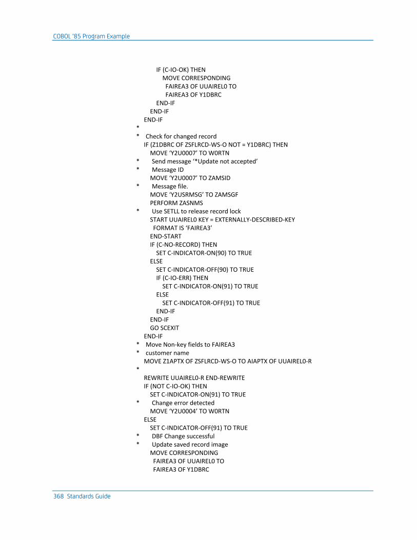
COBOL ‘85 Program Example
368 Standards Guide
IF (C-IO-OK) THEN MOVE CORRESPONDING FAIREA3 OF UUAIREL0 TO FAIREA3 OF Y1DBRC END-IF END-IF END-IF * * Check for changed record IF (Z1DBRC OF ZSFLRCD-WS-O NOT = Y1DBRC) THEN MOVE ‘Y2U0007’ TO W0RTN * Send message ‘*Update not accepted’ * Message ID MOVE ‘Y2U0007’ TO ZAMSID * Message file. MOVE ‘Y2USRMSG’ TO ZAMSGF PERFORM ZASNMS * Use SETLL to release record lock START UUAIREL0 KEY = EXTERNALLY-DESCRIBED-KEY FORMAT IS ‘FAIREA3’ END-START IF (C-NO-RECORD) THEN SET C-INDICATOR-ON(90) TO TRUE ELSE SET C-INDICATOR-OFF(90) TO TRUE IF (C-IO-ERR) THEN SET C-INDICATOR-ON(91) TO TRUE ELSE SET C-INDICATOR-OFF(91) TO TRUE END-IF END-IF GO SCEXIT END-IF * Move Non-key fields to FAIREA3 * customer name MOVE Z1APTX OF ZSFLRCD-WS-O TO AIAPTX OF UUAIREL0-R * REWRITE UUAIREL0-R END-REWRITE IF (NOT C-IO-OK) THEN SET C-INDICATOR-ON(91) TO TRUE * Change error detected MOVE ‘Y2U0004’ TO W0RTN ELSE SET C-INDICATOR-OFF(91) TO TRUE * DBF Change successful * Update saved record image MOVE CORRESPONDING FAIREA3 OF UUAIREL0 TO FAIREA3 OF Y1DBRC
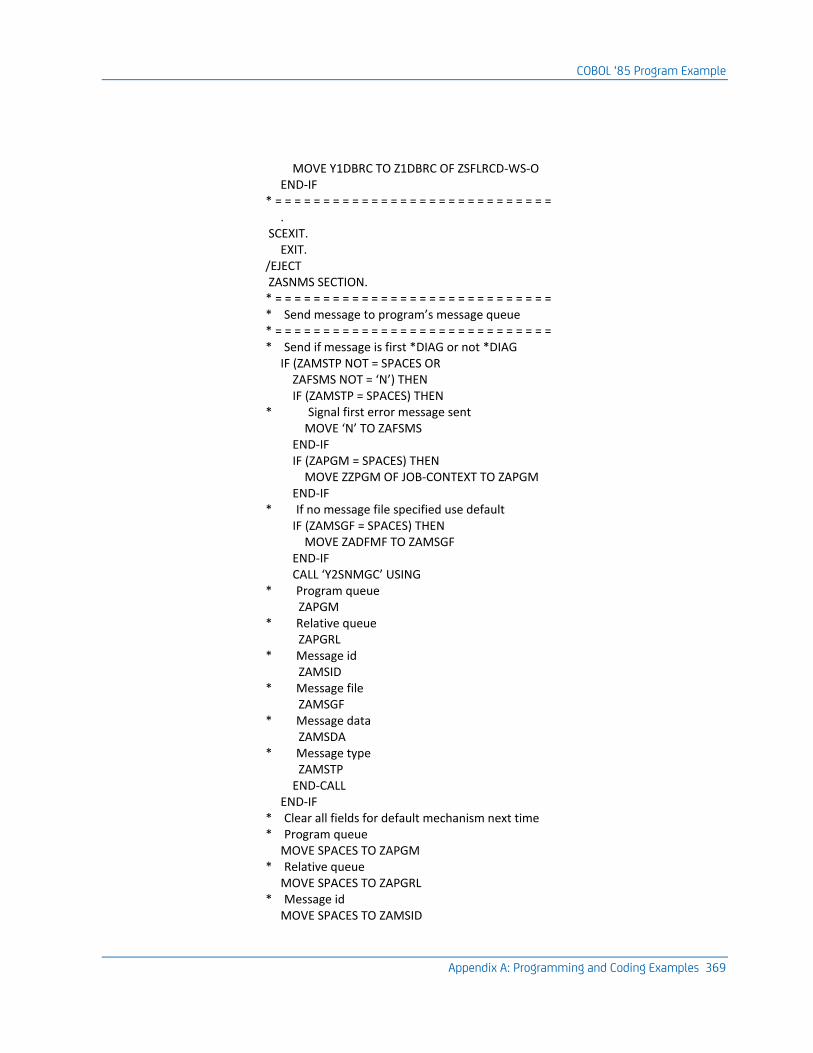
COBOL ‘85 Program Example
Appendix A: Programming and Coding Examples 369
MOVE Y1DBRC TO Z1DBRC OF ZSFLRCD-WS-O END-IF * = = = = = = = = = = = = = = = = = = = = = = = = = = = = = . SCEXIT. EXIT. /EJECT ZASNMS SECTION. * = = = = = = = = = = = = = = = = = = = = = = = = = = = = = * Send message to program’s message queue * = = = = = = = = = = = = = = = = = = = = = = = = = = = = = * Send if message is first *DIAG or not *DIAG IF (ZAMSTP NOT = SPACES OR ZAFSMS NOT = ‘N’) THEN IF (ZAMSTP = SPACES) THEN * Signal first error message sent MOVE ‘N’ TO ZAFSMS END-IF IF (ZAPGM = SPACES) THEN MOVE ZZPGM OF JOB-CONTEXT TO ZAPGM END-IF * If no message file specified use default IF (ZAMSGF = SPACES) THEN MOVE ZADFMF TO ZAMSGF END-IF CALL ‘Y2SNMGC’ USING * Program queue ZAPGM * Relative queue ZAPGRL * Message id ZAMSID * Message file ZAMSGF * Message data ZAMSDA * Message type ZAMSTP END-CALL END-IF * Clear all fields for default mechanism next time * Program queue MOVE SPACES TO ZAPGM * Relative queue MOVE SPACES TO ZAPGRL * Message id MOVE SPACES TO ZAMSID
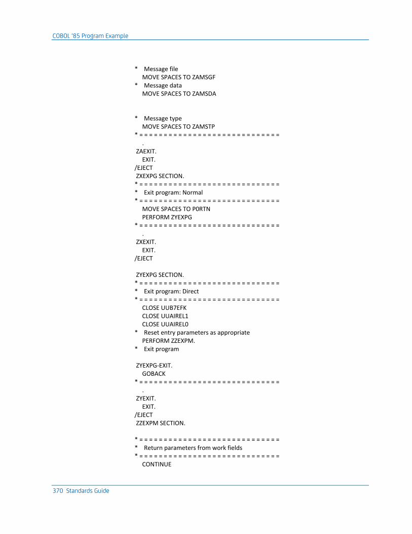
COBOL ‘85 Program Example
370 Standards Guide
* Message file MOVE SPACES TO ZAMSGF * Message data MOVE SPACES TO ZAMSDA * Message type MOVE SPACES TO ZAMSTP * = = = = = = = = = = = = = = = = = = = = = = = = = = = = = . ZAEXIT. EXIT. /EJECT ZXEXPG SECTION. * = = = = = = = = = = = = = = = = = = = = = = = = = = = = = * Exit program: Normal * = = = = = = = = = = = = = = = = = = = = = = = = = = = = = MOVE SPACES TO P0RTN PERFORM ZYEXPG * = = = = = = = = = = = = = = = = = = = = = = = = = = = = = . ZXEXIT. EXIT. /EJECT ZYEXPG SECTION. * = = = = = = = = = = = = = = = = = = = = = = = = = = = = = * Exit program: Direct * = = = = = = = = = = = = = = = = = = = = = = = = = = = = = CLOSE UUB7EFK CLOSE UUAIREL1 CLOSE UUAIREL0 * Reset entry parameters as appropriate PERFORM ZZEXPM. * Exit program ZYEXPG-EXIT. GOBACK * = = = = = = = = = = = = = = = = = = = = = = = = = = = = = . ZYEXIT. EXIT. /EJECT ZZEXPM SECTION. * = = = = = = = = = = = = = = = = = = = = = = = = = = = = = * Return parameters from work fields * = = = = = = = = = = = = = = = = = = = = = = = = = = = = = CONTINUE
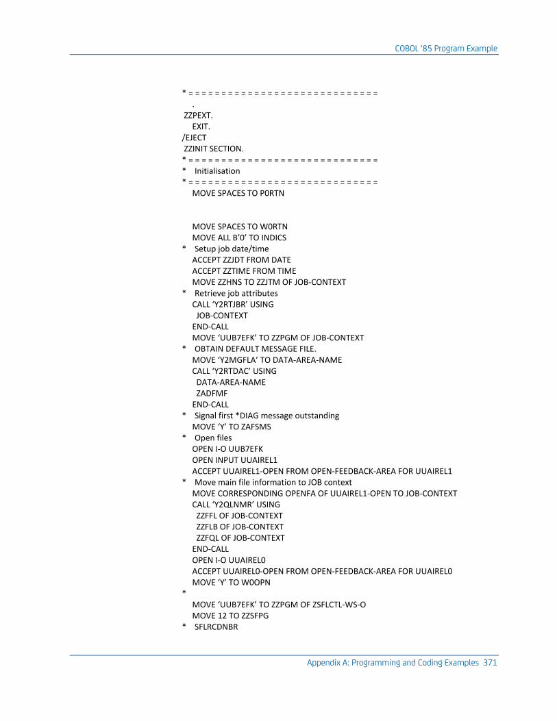
COBOL ‘85 Program Example
Appendix A: Programming and Coding Examples 371
* = = = = = = = = = = = = = = = = = = = = = = = = = = = = = . ZZPEXT. EXIT. /EJECT ZZINIT SECTION. * = = = = = = = = = = = = = = = = = = = = = = = = = = = = = * Initialisation * = = = = = = = = = = = = = = = = = = = = = = = = = = = = = MOVE SPACES TO P0RTN MOVE SPACES TO W0RTN MOVE ALL B’0’ TO INDICS * Setup job date/time ACCEPT ZZJDT FROM DATE ACCEPT ZZTIME FROM TIME MOVE ZZHNS TO ZZJTM OF JOB-CONTEXT * Retrieve job attributes CALL ‘Y2RTJBR’ USING JOB-CONTEXT END-CALL MOVE ‘UUB7EFK’ TO ZZPGM OF JOB-CONTEXT * OBTAIN DEFAULT MESSAGE FILE. MOVE ‘Y2MGFLA’ TO DATA-AREA-NAME CALL ‘Y2RTDAC’ USING DATA-AREA-NAME ZADFMF END-CALL * Signal first *DIAG message outstanding MOVE ‘Y’ TO ZAFSMS * Open files OPEN I-O UUB7EFK OPEN INPUT UUAIREL1 ACCEPT UUAIREL1-OPEN FROM OPEN-FEEDBACK-AREA FOR UUAIREL1 * Move main file information to JOB context MOVE CORRESPONDING OPENFA OF UUAIREL1-OPEN TO JOB-CONTEXT CALL ‘Y2QLNMR’ USING ZZFFL OF JOB-CONTEXT ZZFLB OF JOB-CONTEXT ZZFQL OF JOB-CONTEXT END-CALL OPEN I-O UUAIREL0 ACCEPT UUAIREL0-OPEN FROM OPEN-FEEDBACK-AREA FOR UUAIREL0 MOVE ‘Y’ TO W0OPN * MOVE ‘UUB7EFK’ TO ZZPGM OF ZSFLCTL-WS-O MOVE 12 TO ZZSFPG * SFLRCDNBR
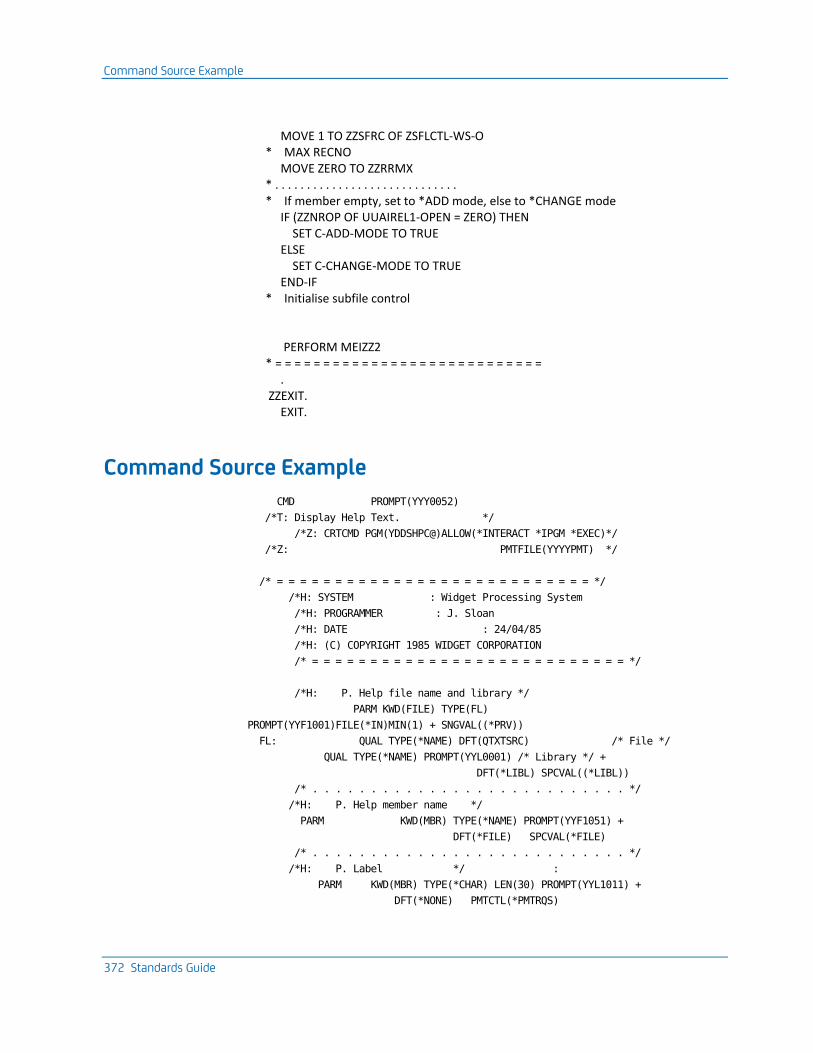
Command Source Example
372 Standards Guide
MOVE 1 TO ZZSFRC OF ZSFLCTL-WS-O * MAX RECNO MOVE ZERO TO ZZRRMX * . . . . . . . . . . . . . . . . . . . . . . . . . . . . . * If member empty, set to *ADD mode, else to *CHANGE mode IF (ZZNROP OF UUAIREL1-OPEN = ZERO) THEN SET C-ADD-MODE TO TRUE ELSE SET C-CHANGE-MODE TO TRUE END-IF * Initialise subfile control PERFORM MEIZZ2 * = = = = = = = = = = = = = = = = = = = = = = = = = = = = . ZZEXIT. EXIT.
Command Source Example
CMD PROMPT(YYY0052)
/*T: Display Help Text. */
/*Z: CRTCMD PGM(YDDSHPC@)ALLOW(*INTERACT *IPGM *EXEC)*/
/*Z: PMTFILE(YYYYPMT) */
/* = = = = = = = = = = = = = = = = = = = = = = = = = = = */
/*H: SYSTEM : Widget Processing System
/*H: PROGRAMMER : J. Sloan
/*H: DATE : 24/04/85
/*H: (C) COPYRIGHT 1985 WIDGET CORPORATION
/* = = = = = = = = = = = = = = = = = = = = = = = = = = = */
/*H: P. Help file name and library */
PARM KWD(FILE) TYPE(FL)
PROMPT(YYF1001)FILE(*IN)MIN(1) + SNGVAL((*PRV))
FL: QUAL TYPE(*NAME) DFT(QTXTSRC) /* File */
QUAL TYPE(*NAME) PROMPT(YYL0001) /* Library */ +
DFT(*LIBL) SPCVAL((*LIBL))
/* . . . . . . . . . . . . . . . . . . . . . . . . . . . */
/*H: P. Help member name */
PARM KWD(MBR) TYPE(*NAME) PROMPT(YYF1051) +
DFT(*FILE) SPCVAL(*FILE)
/* . . . . . . . . . . . . . . . . . . . . . . . . . . . */
/*H: P. Label */ :
PARM KWD(MBR) TYPE(*CHAR) LEN(30) PROMPT(YYL1011) +
DFT(*NONE) PMTCTL(*PMTRQS)
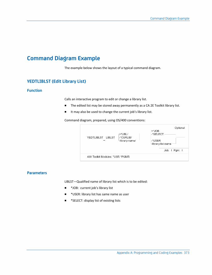
Command Diagram Example
Appendix A: Programming and Coding Examples 373
Command Diagram Example
The example below shows the layout of a typical command diagram.
YEDTLIBLST (Edit Library List)
Function
Calls an interactive program to edit or change a library list.
■ The edited list may be stored away permanently as a CA 2E Toolkit library list.
■ It may also be used to change the current job’s library list.
Command diagram, prepared, using OS/400 conventions:
Parameters
LIBLST—Qualified name of library list which is to be edited:
■ *JOB: current job’s library list
■ *USER: library list has same name as user
■ *SELECT: display list of existing lists
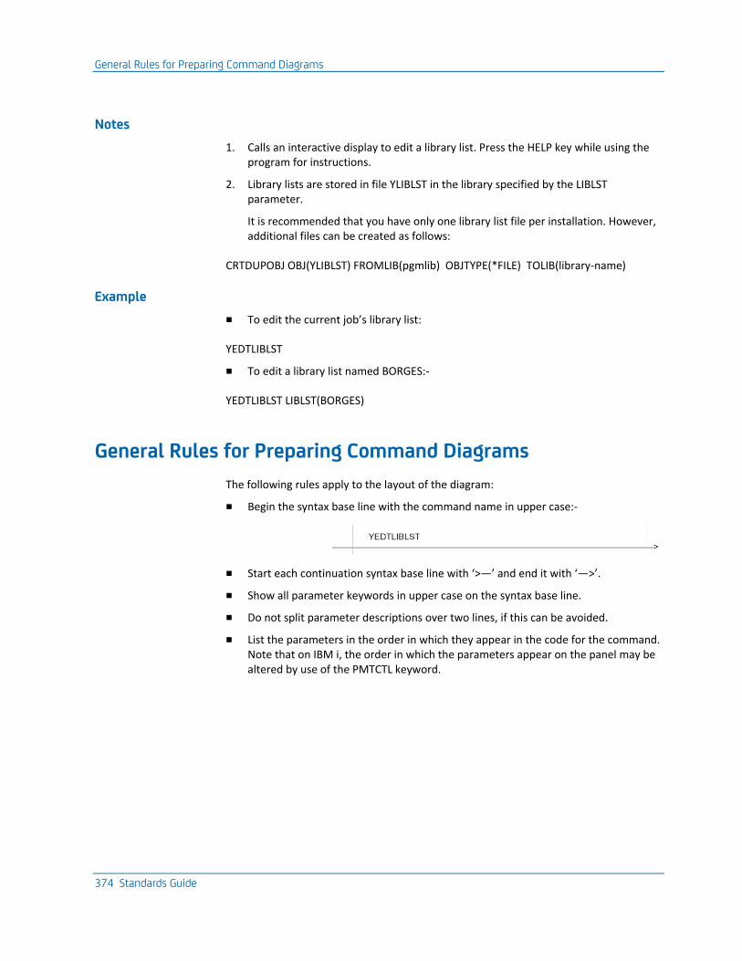
General Rules for Preparing Command Diagrams
374 Standards Guide
Notes
1. Calls an interactive display to edit a library list. Press the HELP key while using the program for instructions.
2. Library lists are stored in file YLIBLST in the library specified by the LIBLST parameter.
It is recommended that you have only one library list file per installation. However, additional files can be created as follows:
CRTDUPOBJ OBJ(YLIBLST) FROMLIB(pgmlib) OBJTYPE(*FILE) TOLIB(library-name)
Example
■ To edit the current job’s library list:
YEDTLIBLST
■ To edit a library list named BORGES:-
YEDTLIBLST LIBLST(BORGES)
General Rules for Preparing Command Diagrams
The following rules apply to the layout of the diagram:
■ Begin the syntax base line with the command name in upper case:-
■ Start each continuation syntax base line with ‘>—’ and end it with ‘—>’.
■ Show all parameter keywords in upper case on the syntax base line.
■ Do not split parameter descriptions over two lines, if this can be avoided.
■ List the parameters in the order in which they appear in the code for the command. Note that on IBM i, the order in which the parameters appear on the panel may be altered by use of the PMTCTL keyword.
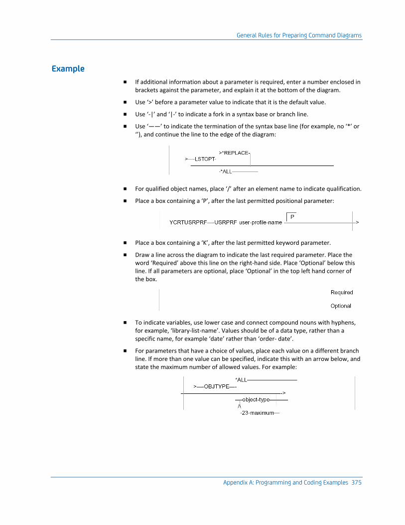
General Rules for Preparing Command Diagrams
Appendix A: Programming and Coding Examples 375
Example
■ If additional information about a parameter is required, enter a number enclosed in brackets against the parameter, and explain it at the bottom of the diagram.
■ Use ‘>’ before a parameter value to indicate that it is the default value.
■ Use ‘-|’ and ‘|-’ to indicate a fork in a syntax base or branch line.
■ Use ‘——’ to indicate the termination of the syntax base line (for example, no ‘*’ or ‘’), and continue the line to the edge of the diagram:
■ For qualified object names, place ‘/’ after an element name to indicate qualification.
■ Place a box containing a ‘P’, after the last permitted positional parameter:
■ Place a box containing a ‘K’, after the last permitted keyword parameter.
■ Draw a line across the diagram to indicate the last required parameter. Place the word ‘Required’ above this line on the right-hand side. Place ‘Optional’ below this line. If all parameters are optional, place ‘Optional’ in the top left hand corner of the box.
■ To indicate variables, use lower case and connect compound nouns with hyphens, for example, ‘library-list-name’. Values should be of a data type, rather than a specific name, for example ‘date’ rather than ‘order- date’.
■ For parameters that have a choice of values, place each value on a different branch line. If more than one value can be specified, indicate this with an arrow below, and state the maximum number of allowed values. For example:
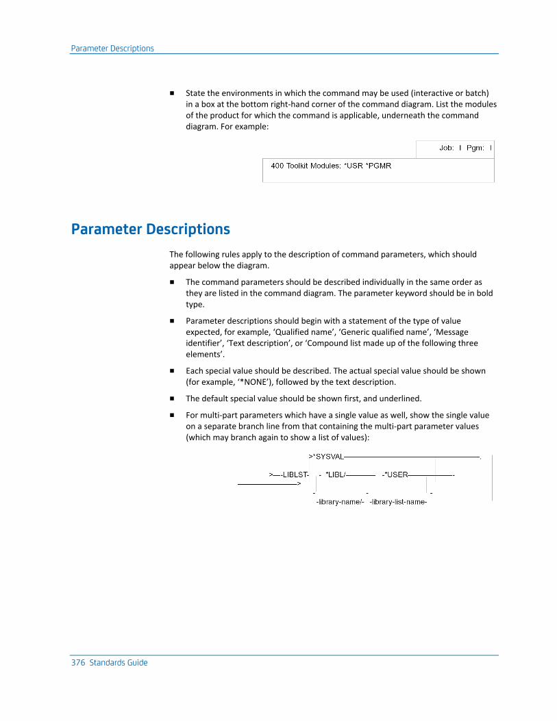
Parameter Descriptions
376 Standards Guide
■ State the environments in which the command may be used (interactive or batch) in a box at the bottom right-hand corner of the command diagram. List the modules of the product for which the command is applicable, underneath the command diagram. For example:
Parameter Descriptions
The following rules apply to the description of command parameters, which should appear below the diagram.
■ The command parameters should be described individually in the same order as they are listed in the command diagram. The parameter keyword should be in bold type.
■ Parameter descriptions should begin with a statement of the type of value expected, for example, ‘Qualified name’, ‘Generic qualified name’, ‘Message identifier’, ‘Text description’, or ‘Compound list made up of the following three elements’.
■ Each special value should be described. The actual special value should be shown (for example, ‘*NONE’), followed by the text description.
■ The default special value should be shown first, and underlined.
■ For multi-part parameters which have a single value as well, show the single value on a separate branch line from that containing the multi-part parameter values (which may branch again to show a list of values):
UIM Help Text Example
Appendix A: Programming and Coding Examples 377
The following rule applies to the notes on using the command:
■ Notes should explain additional specific information that is required to use the command or understand its actions. Information pertaining to particular parameters should normally appear in the parameter description, not in the notes.
The following rule applies to the examples of using the command which should appear at the end:
■ Examples should cite at least one instance of using the command. Give a typical example or examples.
YEDTLIBLST LIBLST(BORGES)
UIM Help Text Example
This section contains sample source for UIM help text. There are separate examples for Command help, Panel help, Search index, and Hypertext definitions.
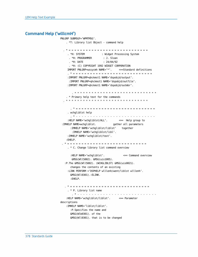
UIM Help Text Example
378 Standards Guide
Command Help (‘wlllcmH’) PNLGRP SUBMSGF=’WPMTMSG’.
. *T: Library list Object - command help
. * = = = = = = = = = = = = = = = = = = = = = = = = = = = =
. *H: SYSTEM : Widget Processing System
. *H: PROGRAMMER : J. Sloan
. *H: DATE : 24/04/92
. *H: (C) COPYRIGHT 1992 WIDGET CORPORATION
IMPORT PNLGRP=wssycmh NAME=’*’. <==Standard definitions
. * = = = = = = = = = = = = = = = = = = = = = = = = = = = =
:IMPORT PNLGRP=qhckmst1 NAME=’dspobjd/output’.
:IMPORT PNLGRP=qhckmst1 NAME=’dspobjd/outfile’.
:IMPORT PNLGRP=qhckmst1 NAME=’dspobjd/outmbr’.
. * * * * * * * * * * * * * * * * * * * * * * * * * * * * *
. * Primary help text for the commands
. * * * * * * * * * * * * * * * * * * * * * * * * * * * * *
. * = = = = = = = = = = = = = = = = = = = = = = = = = = = =
. wchgliblst help
. * - - - - - - - - - - - - - - - - - - - - - - - - - - - -
:HELP NAME=’wchgliblst/ALL’. <== Help group to
:IMHELP NAME=wchgliblst. gather all parameters
:IMHELP NAME=’wchgliblst/liblst’ together
:IMHELP NAME=’wchgliblst/libl’.
:IMHELP NAME=’wchgliblst/text’.
:EHELP.
. * = = = = = = = = = = = = = = = = = = = = = = = = = = = =
. * C. Change library list command overview
:HELP NAME=’wchgliblst’. <== Command overview
&MSG(Wll5002). &MSG(uis1005).
:P.The &MSG(Wll5002). (WCHGLIBLST) &MSG(uis0021).
changes the contents of an existing
:LINK PERFORM =’DSPHELP wlllenh/went/liblst wlllenh’.
&MSG(Wll0301).:ELINK.
:EHELP.
. * = = = = = = = = = = = = = = = = = = = = = = = = = = = =
. * P. Library list name
. * - - - - - - - - - - - - - - - - - - - - - - - - - - - -
:HELP NAME=’wchgliblst/liblst’. <== Parameter
descriptions
:IMHELP NAME=’liblst/liblst’.
:P.Specifies the name and
&MSG(Wlb0301). of the
&MSG(Wll0301). that is to be changed
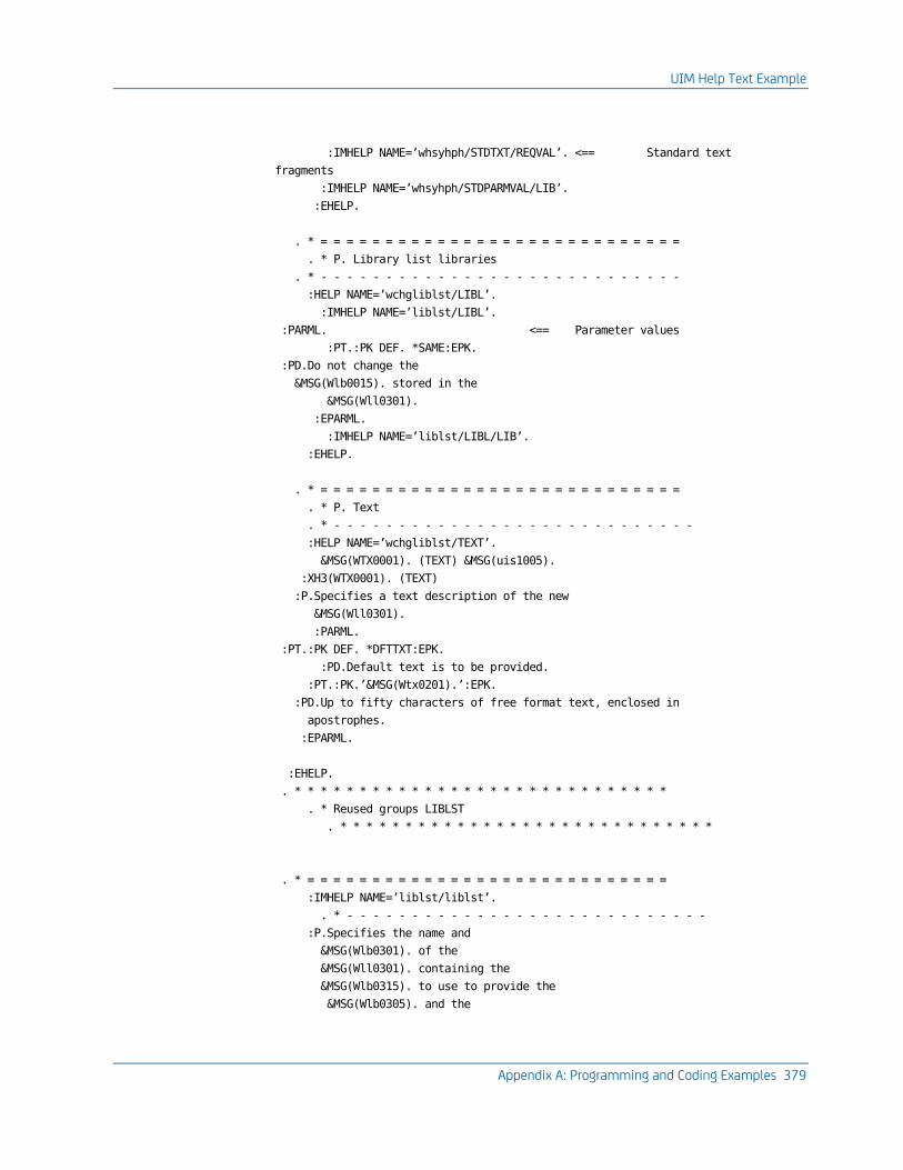
UIM Help Text Example
Appendix A: Programming and Coding Examples 379
:IMHELP NAME=’whsyhph/STDTXT/REQVAL’. <== Standard text
fragments
:IMHELP NAME=’whsyhph/STDPARMVAL/LIB’.
:EHELP.
. * = = = = = = = = = = = = = = = = = = = = = = = = = = = =
. * P. Library list libraries
. * - - - - - - - - - - - - - - - - - - - - - - - - - - - -
:HELP NAME=’wchgliblst/LIBL’.
:IMHELP NAME=’liblst/LIBL’.
:PARML. <== Parameter values
:PT.:PK DEF. *SAME:EPK.
:PD.Do not change the
&MSG(Wlb0015). stored in the
&MSG(Wll0301).
:EPARML.
:IMHELP NAME=’liblst/LIBL/LIB’.
:EHELP.
. * = = = = = = = = = = = = = = = = = = = = = = = = = = = =
. * P. Text
. * - - - - - - - - - - - - - - - - - - - - - - - - - - - -
:HELP NAME=’wchgliblst/TEXT’.
&MSG(WTX0001). (TEXT) &MSG(uis1005).
:XH3(WTX0001). (TEXT)
:P.Specifies a text description of the new
&MSG(Wll0301).
:PARML.
:PT.:PK DEF. *DFTTXT:EPK.
:PD.Default text is to be provided.
:PT.:PK.’&MSG(Wtx0201).’:EPK.
:PD.Up to fifty characters of free format text, enclosed in
apostrophes.
:EPARML.
:EHELP.
. * * * * * * * * * * * * * * * * * * * * * * * * * * * * *
. * Reused groups LIBLST
. * * * * * * * * * * * * * * * * * * * * * * * * * * * * *
. * = = = = = = = = = = = = = = = = = = = = = = = = = = = =
:IMHELP NAME=’liblst/liblst’.
. * - - - - - - - - - - - - - - - - - - - - - - - - - - - -
:P.Specifies the name and
&MSG(Wlb0301). of the
&MSG(Wll0301). containing the
&MSG(Wlb0315). to use to provide the
&MSG(Wlb0305). and the
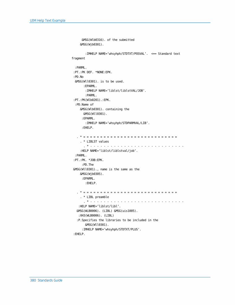
UIM Help Text Example
380 Standards Guide
&MSG(Wlb0316). of the submitted
&MSG(Wjb0301).
:IMHELP NAME=’whsyhph/STDTXT/POSVAL’. <== Standard text
fragment
:PARML.
:PT.:PK DEF. *NONE:EPK.
:PD.No
&MSG(Wll0301). is to be used.
:EPARML.
:IMHELP NAME=’liblst/liblstVAL/JOB’.
:PARML.
:PT.:PK(Wlb0201).:EPK.
:PD.Name of
&MSG(Wlb0301). containing the
&MSG(Wll0301).
:EPARML.
:IMHELP NAME=’whsyhph/STDPARMVAL/LIB’.
:EHELP.
. * = = = = = = = = = = = = = = = = = = = = = = = = = = = =
. * LIBLST values
. * - - - - - - - - - - - - - - - - - - - - - - - - - - - -
:HELP NAME=’liblst/liblstval/job’.
:PARML.
:PT.:PK. *JOB:EPK.
:PD.The
&MSG(Wll0301)., name is the same as the
&MSG(Wjb0305).
:EPARML.
:EHELP.
. * = = = = = = = = = = = = = = = = = = = = = = = = = = = =
. * LIBL preamble
. * - - - - - - - - - - - - - - - - - - - - - - - - - - - -
:HELP NAME=’liblst/libl’.
&MSG(WLB0006). (LIBL) &MSG(uis1005).
:XH3(WLB0006). (LIBL)
:P.Specifies the libraries to be included in the
&MSG(Wll0301).
:IMHELP NAME=’whsyhph/STDTXT/PLUS’.
:EHELP.
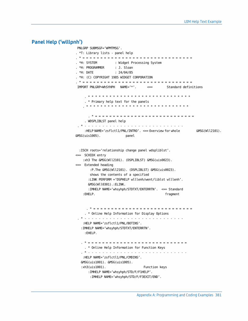
UIM Help Text Example
Appendix A: Programming and Coding Examples 381
Panel Help (‘wlllpnh’) PNLGRP SUBMSGF=’WPMTMSG’.
. *T: Library lists - panel help
. * = = = = = = = = = = = = = = = = = = = = = = = = = = = = = = =
. *H: SYSTEM : Widget Processing System
. *H: PROGRAMMER : J. Sloan
. *H: DATE : 24/04/85
. *H: (C) COPYRIGHT 1985 WIDGET CORPORATION
. * = = = = = = = = = = = = = = = = = = = = = = = = = = = = = = =
IMPORT PNLGRP=WhSYHPH NAME=’*’. <== Standard definitions
. * * * * * * * * * * * * * * * * * * * * * * * * * * * * *
. * Primary help text for the panels
. * * * * * * * * * * * * * * * * * * * * * * * * * * * * *
. * = = = = = = = = = = = = = = = = = = = = = = = = = = = =
. WDSPLIBLST panel help
. * - - - - - - - - - - - - - - - - - - - - - - - - - - - -
:HELP NAME=’zsflctl1/PNL/INTRO’. <== Overview for whole &MSG(Wll2101).
&MSG(uis1005). panel
:ISCH roots=’relationship change panel wdspliblst’.
<== SCHIDX entry
:xh3 The &MSG(Wll2101). (DSPLIBLST) &MSG(uis0023).
<== Extended heading
:P.The &MSG(Wll2101). (DSPLIBLST) &MSG(uis0023).
shows the contents of a specified
:LINK PERFORM =’DSPHELP wlllenh/went/liblst wlllenh’.
&MSG(Wll0301).:ELINK.
:IMHELP NAME=’whsyhph/STDTXT/ENTERRTN’. <== Standard
:EHELP. fragment
. * = = = = = = = = = = = = = = = = = = = = = = = = = = = =
. * Online Help Information for Display Options
. * - - - - - - - - - - - - - - - - - - - - - - - - - - - -
:HELP NAME=’zsflctl1/PNL/BOTINS’.
:IMHELP NAME=’whsyhph/STDTXT/ENTERRTN’.
:EHELP.
. * = = = = = = = = = = = = = = = = = = = = = = = = = = = =
. * Online Help Information for Function Keys
. * - - - - - - - - - - - - - - - - - - - - - - - - - - - -
:HELP NAME=’zsflctl1/PNL/CMDINS’.
&MSG(uis1001). &MSG(uis1005).
:xh3(uis1001). Function keys
:IMHELP NAME=’whsyhph/STD/F/F1HELP’.
:IMHELP NAME=’whsyhph/STD/F/F3EXIT/END’.
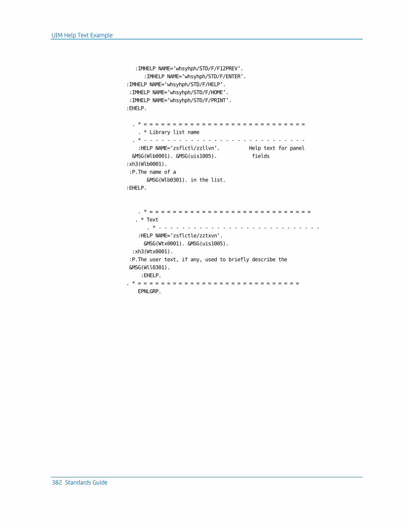
UIM Help Text Example
382 Standards Guide
:IMHELP NAME=’whsyhph/STD/F/F12PREV’.
:IMHELP NAME=’whsyhph/STD/F/ENTER’.
:IMHELP NAME=’whsyhph/STD/F/HELP’.
:IMHELP NAME=’whsyhph/STD/F/HOME’.
:IMHELP NAME=’whsyhph/STD/F/PRINT’.
:EHELP.
. * = = = = = = = = = = = = = = = = = = = = = = = = = = = =
. * Library list name
. * - - - - - - - - - - - - - - - - - - - - - - - - - - - -
:HELP NAME=’zsflctl/zzllvn’. Help text for panel
&MSG(Wlb0001). &MSG(uis1005). fields
:xh3(Wlb0001).
:P.The name of a
&MSG(Wlb0301). in the list.
:EHELP.
. * = = = = = = = = = = = = = = = = = = = = = = = = = = = =
. * Text
. * - - - - - - - - - - - - - - - - - - - - - - - - - - - -
:HELP NAME=’zsflctle/zztxvn’.
&MSG(Wtx0001). &MSG(uis1005).
:xh3(Wtx0001).
:P.The user text, if any, used to briefly describe the
&MSG(Wll0301).
:EHELP.
. * = = = = = = = = = = = = = = = = = = = = = = = = = = = =
EPNLGRP.
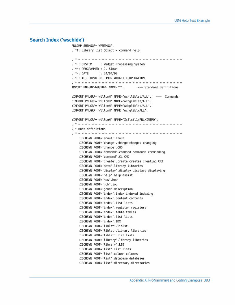
UIM Help Text Example
Appendix A: Programming and Coding Examples 383
Search Index (‘wschidx’) PNLGRP SUBMSGF=’WPMTMSG’.
. *T: Library list Object - command help
. * = = = = = = = = = = = = = = = = = = = = = = = = = = = = = = =
. *H: SYSTEM : Widget Processing System
. *H: PROGRAMMER : J. Sloan
. *H: DATE : 24/04/92
. *H: (C) COPYRIGHT 1992 WIDGET CORPORATION
. * = = = = = = = = = = = = = = = = = = = = = = = = = = = = = = =
IMPORT PNLGRP=WHSYHPH NAME=’*’. <== Standard definitions
:IMPORT PNLGRP=’wlllcmH’ NAME=’wcrtliblst/ALL’. <== Commands
:IMPORT PNLGRP=’WlllcmH’ NAME=’wchgliblst/ALL’.
:IMPORT PNLGRP=’WlllcmH’ NAME=’wdspliblst/ALL’.
:IMPORT PNLGRP=’WlllcmH’ NAME=’wchglibl/ALL’.
:IMPORT PNLGRP=’wlllpnH’ NAME=’Zsflctl1/PNL/INTRO’.
. * = = = = = = = = = = = = = = = = = = = = = = = = = = = = = = =
. * Root definitions
. * = = = = = = = = = = = = = = = = = = = = = = = = = = = = = = =
:ISCHSYN ROOT=’about’.about
:ISCHSYN ROOT=’change’.change changes changing
:ISCHSYN ROOT=’change’.CHG
:ISCHSYN ROOT=’command’.command commands commanding
:ISCHSYN ROOT=’command’.CL CMD
:ISCHSYN ROOT=’create’.create creates creating CRT
:ISCHSYN ROOT=’data’.library libraries
:ISCHSYN ROOT=’display’.display displays displaying
:ISCHSYN ROOT=’help’.help assist
:ISCHSYN ROOT=’how’.how
:ISCHSYN ROOT=’job’.job
:ISCHSYN ROOT=’jobd’.description
:ISCHSYN ROOT=’index’.index indexed indexing
:ISCHSYN ROOT=’index’.content contents
:ISCHSYN ROOT=’index’.list lists
:ISCHSYN ROOT=’index’.register registers
:ISCHSYN ROOT=’index’.table tables
:ISCHSYN ROOT=’index’.list lists
:ISCHSYN ROOT=’index’.IDX
:ISCHSYN ROOT=’liblst’.liblst
:ISCHSYN ROOT=’liblst’.library libraries
:ISCHSYN ROOT=’liblst’.list lists
:ISCHSYN ROOT=’library’.library libraries
:ISCHSYN ROOT=’library’.LIB
:ISCHSYN ROOT=’list’.list lists
:ISCHSYN ROOT=’list’.column columns
:ISCHSYN ROOT=’list’.database databases
:ISCHSYN ROOT=’list’.directory directories
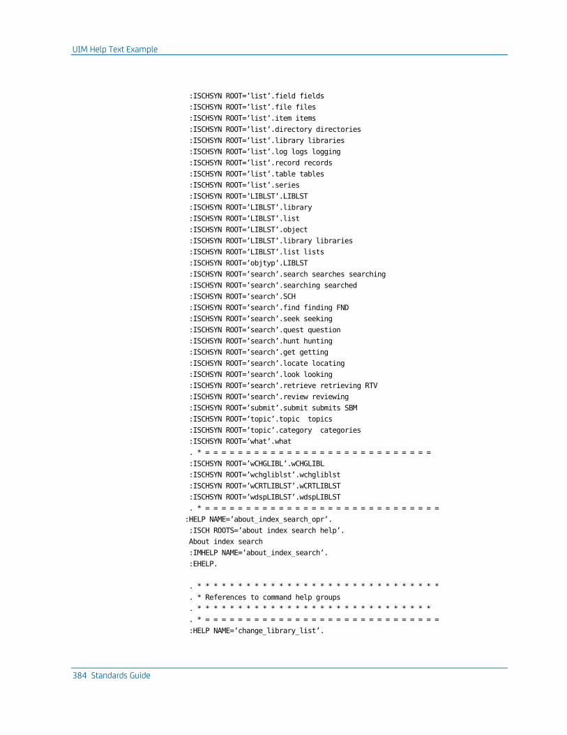
UIM Help Text Example
384 Standards Guide
:ISCHSYN ROOT=’list’.field fields
:ISCHSYN ROOT=’list’.file files
:ISCHSYN ROOT=’list’.item items
:ISCHSYN ROOT=’list’.directory directories
:ISCHSYN ROOT=’list’.library libraries
:ISCHSYN ROOT=’list’.log logs logging
:ISCHSYN ROOT=’list’.record records
:ISCHSYN ROOT=’list’.table tables
:ISCHSYN ROOT=’list’.series
:ISCHSYN ROOT=’LIBLST’.LIBLST
:ISCHSYN ROOT=’LIBLST’.library
:ISCHSYN ROOT=’LIBLST’.list
:ISCHSYN ROOT=’LIBLST’.object
:ISCHSYN ROOT=’LIBLST’.library libraries
:ISCHSYN ROOT=’LIBLST’.list lists
:ISCHSYN ROOT=’objtyp’.LIBLST
:ISCHSYN ROOT=’search’.search searches searching
:ISCHSYN ROOT=’search’.searching searched
:ISCHSYN ROOT=’search’.SCH
:ISCHSYN ROOT=’search’.find finding FND
:ISCHSYN ROOT=’search’.seek seeking
:ISCHSYN ROOT=’search’.quest question
:ISCHSYN ROOT=’search’.hunt hunting
:ISCHSYN ROOT=’search’.get getting
:ISCHSYN ROOT=’search’.locate locating
:ISCHSYN ROOT=’search’.look looking
:ISCHSYN ROOT=’search’.retrieve retrieving RTV
:ISCHSYN ROOT=’search’.review reviewing
:ISCHSYN ROOT=’submit’.submit submits SBM
:ISCHSYN ROOT=’topic’.topic topics
:ISCHSYN ROOT=’topic’.category categories
:ISCHSYN ROOT=’what’.what
. * = = = = = = = = = = = = = = = = = = = = = = = = = = = =
:ISCHSYN ROOT=’wCHGLIBL’.wCHGLIBL
:ISCHSYN ROOT=’wchgliblst’.wchgliblst
:ISCHSYN ROOT=’wCRTLIBLST’.wCRTLIBLST
:ISCHSYN ROOT=’wdspLIBLST’.wdspLIBLST
. * = = = = = = = = = = = = = = = = = = = = = = = = = = = = =
:HELP NAME=’about_index_search_opr’.
:ISCH ROOTS=’about index search help’.
About index search
:IMHELP NAME=’about_index_search’.
:EHELP.
. * * * * * * * * * * * * * * * * * * * * * * * * * * * * * *
. * References to command help groups
. * * * * * * * * * * * * * * * * * * * * * * * * * * * * *
. * = = = = = = = = = = = = = = = = = = = = = = = = = = = = =
:HELP NAME=’change_library_list’.
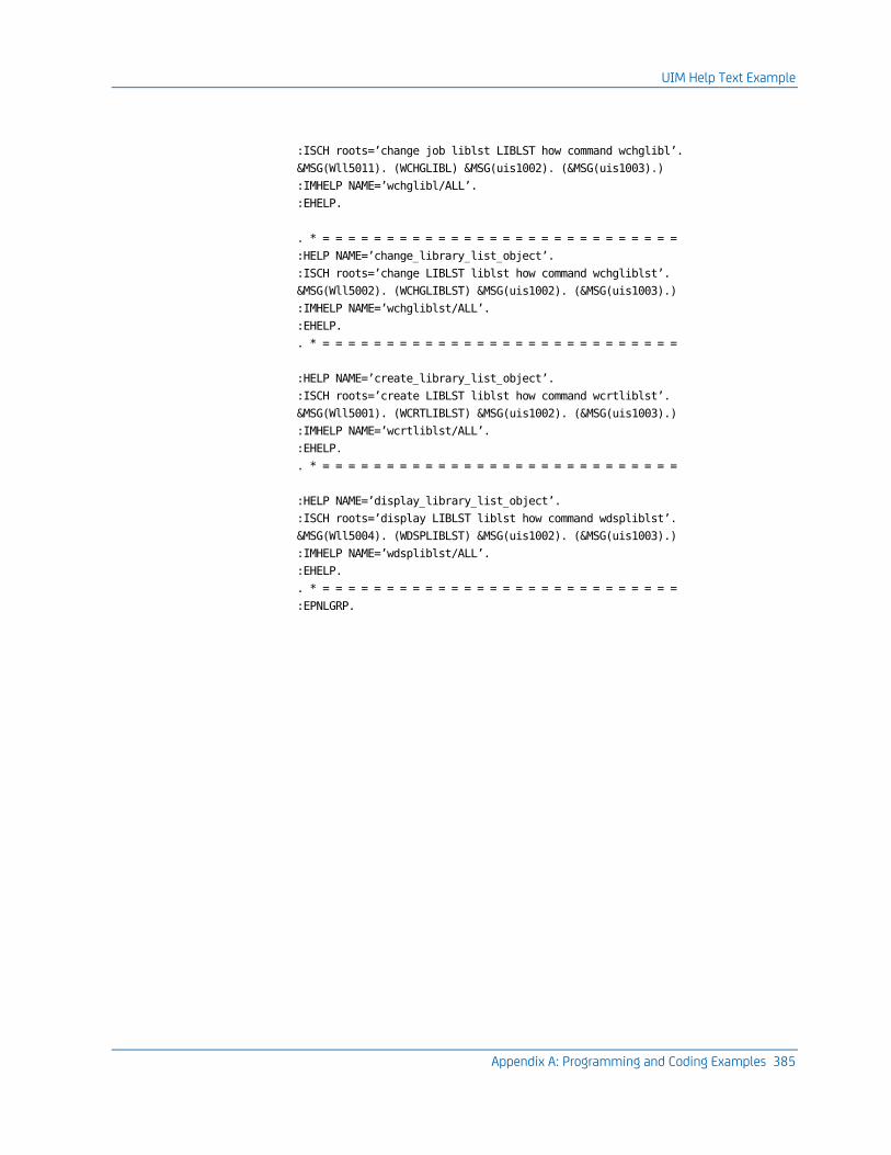
UIM Help Text Example
Appendix A: Programming and Coding Examples 385
:ISCH roots=’change job liblst LIBLST how command wchglibl’.
&MSG(Wll5011). (WCHGLIBL) &MSG(uis1002). (&MSG(uis1003).)
:IMHELP NAME=’wchglibl/ALL’.
:EHELP.
. * = = = = = = = = = = = = = = = = = = = = = = = = = = = =
:HELP NAME=’change_library_list_object’.
:ISCH roots=’change LIBLST liblst how command wchgliblst’.
&MSG(Wll5002). (WCHGLIBLST) &MSG(uis1002). (&MSG(uis1003).)
:IMHELP NAME=’wchgliblst/ALL’.
:EHELP.
. * = = = = = = = = = = = = = = = = = = = = = = = = = = = =
:HELP NAME=’create_library_list_object’.
:ISCH roots=’create LIBLST liblst how command wcrtliblst’.
&MSG(Wll5001). (WCRTLIBLST) &MSG(uis1002). (&MSG(uis1003).)
:IMHELP NAME=’wcrtliblst/ALL’.
:EHELP.
. * = = = = = = = = = = = = = = = = = = = = = = = = = = = =
:HELP NAME=’display_library_list_object’.
:ISCH roots=’display LIBLST liblst how command wdspliblst’.
&MSG(Wll5004). (WDSPLIBLST) &MSG(uis1002). (&MSG(uis1003).)
:IMHELP NAME=’wdspliblst/ALL’.
:EHELP.
. * = = = = = = = = = = = = = = = = = = = = = = = = = = = =
:EPNLGRP.
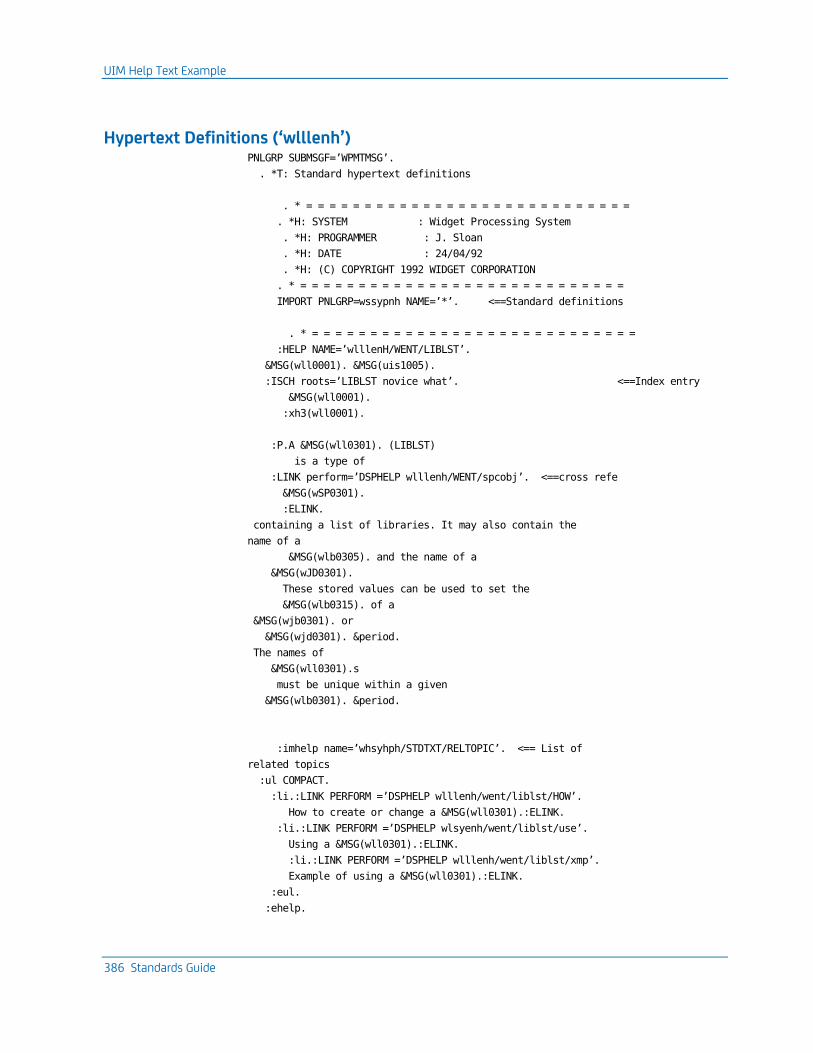
UIM Help Text Example
386 Standards Guide
Hypertext Definitions (‘wlllenh’) PNLGRP SUBMSGF=’WPMTMSG’.
. *T: Standard hypertext definitions
. * = = = = = = = = = = = = = = = = = = = = = = = = = = = =
. *H: SYSTEM : Widget Processing System
. *H: PROGRAMMER : J. Sloan
. *H: DATE : 24/04/92
. *H: (C) COPYRIGHT 1992 WIDGET CORPORATION
. * = = = = = = = = = = = = = = = = = = = = = = = = = = = =
IMPORT PNLGRP=wssypnh NAME=’*’. <==Standard definitions
. * = = = = = = = = = = = = = = = = = = = = = = = = = = = =
:HELP NAME=’wlllenH/WENT/LIBLST’.
&MSG(wll0001). &MSG(uis1005).
:ISCH roots=’LIBLST novice what’. <==Index entry
&MSG(wll0001).
:xh3(wll0001).
:P.A &MSG(wll0301). (LIBLST)
is a type of
:LINK perform=’DSPHELP wlllenh/WENT/spcobj’. <==cross refe
&MSG(wSP0301).
:ELINK.
containing a list of libraries. It may also contain the
name of a
&MSG(wlb0305). and the name of a
&MSG(wJD0301).
These stored values can be used to set the
&MSG(wlb0315). of a
&MSG(wjb0301). or
&MSG(wjd0301). &period.
The names of
&MSG(wll0301).s
must be unique within a given
&MSG(wlb0301). &period.
:imhelp name=’whsyhph/STDTXT/RELTOPIC’. <== List of
related topics
:ul COMPACT.
:li.:LINK PERFORM =’DSPHELP wlllenh/went/liblst/HOW’.
How to create or change a &MSG(wll0301).:ELINK.
:li.:LINK PERFORM =’DSPHELP wlsyenh/went/liblst/use’.
Using a &MSG(wll0301).:ELINK.
:li.:LINK PERFORM =’DSPHELP wlllenh/went/liblst/xmp’.
Example of using a &MSG(wll0301).:ELINK.
:eul.
:ehelp.

UIM Help Text Example
Appendix A: Programming and Coding Examples 387
. . . . . . etc
:EPNLGRP.

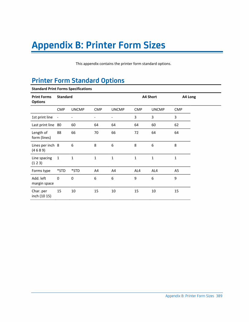
Appendix B: Printer Form Sizes 389
Appendix B: Printer Form Sizes
This appendix contains the printer form standard options.
Printer Form Standard Options Standard Print Forms Specifications
Print Forms Options
Standard A4 Short A4 Long
CMP UNCMP CMP UNCMP CMP UNCMP CMP
1st print line - - - - 3 3 3
Last print line 80 60 64 64 64 60 62
Length of form (lines)
88 66 70 66 72 64 64
Lines per inch (4 6 8 9)
8 6 8 6 8 6 8
Line spacing (1 2 3)
1 1 1 1 1 1 1
Forms type *STD *STD A4 A4 AL4 AL4 A5
Add. left margin space
0 0 6 6 9 6 9
Char. per inch (10 15)
15 10 15 10 15 10 15

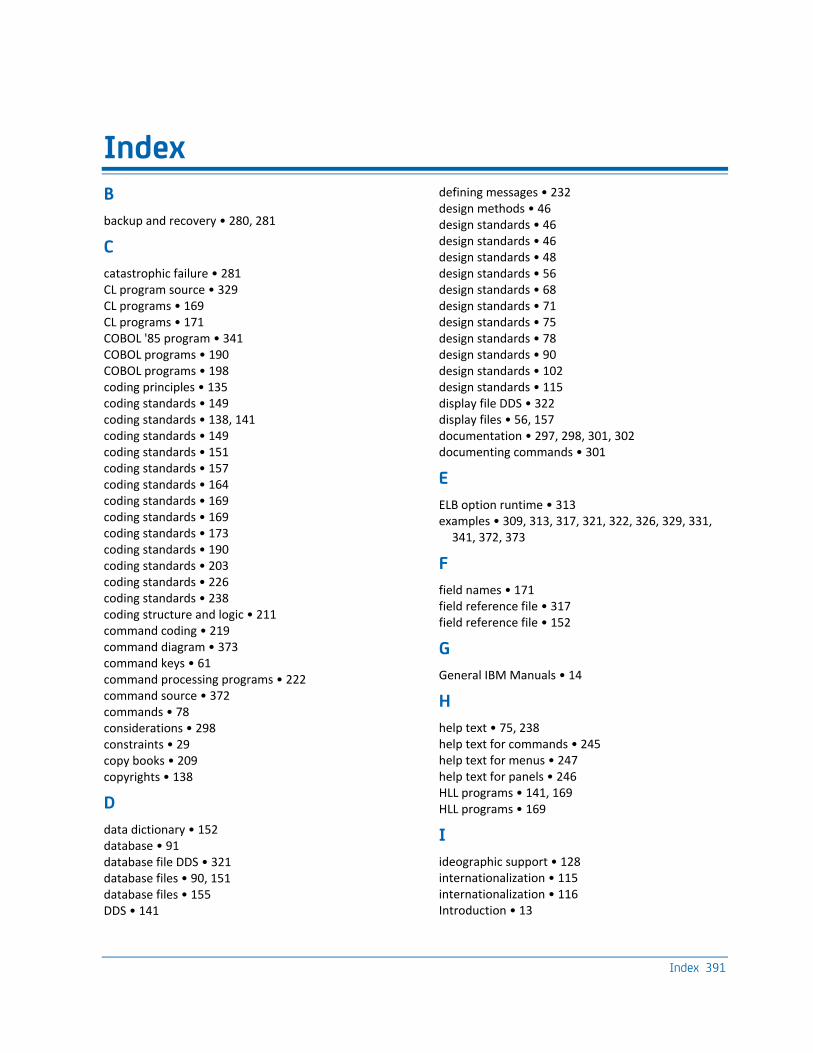
Index 391
Index
B
backup and recovery • 280, 281
C
catastrophic failure • 281 CL program source • 329 CL programs • 169 CL programs • 171 COBOL '85 program • 341 COBOL programs • 190 COBOL programs • 198 coding principles • 135 coding standards • 149 coding standards • 138, 141 coding standards • 149 coding standards • 151 coding standards • 157 coding standards • 164 coding standards • 169 coding standards • 169 coding standards • 173 coding standards • 190 coding standards • 203 coding standards • 226 coding standards • 238 coding structure and logic • 211 command coding • 219 command diagram • 373 command keys • 61 command processing programs • 222 command source • 372 commands • 78 considerations • 298 constraints • 29 copy books • 209 copyrights • 138
D
data dictionary • 152 database • 91 database file DDS • 321 database files • 90, 151 database files • 155 DDS • 141
defining messages • 232 design methods • 46 design standards • 46 design standards • 46 design standards • 48 design standards • 56 design standards • 68 design standards • 71 design standards • 75 design standards • 78 design standards • 90 design standards • 102 design standards • 115 display file DDS • 322 display files • 56, 157 documentation • 297, 298, 301, 302 documenting commands • 301
E
ELB option runtime • 313 examples • 309, 313, 317, 321, 322, 326, 329, 331,
341, 372, 373
F
field names • 171 field reference file • 317 field reference file • 152
G
General IBM Manuals • 14
H
help text • 75, 238 help text for commands • 245 help text for menus • 247 help text for panels • 246 HLL programs • 141, 169 HLL programs • 169
I
ideographic support • 128 internationalization • 115 internationalization • 116 Introduction • 13
392 Standards Guide
iSeries • 46, 149 iSeries • 16, 24 iSeries • 46 iSeries • 91 iSeries • 149 iSeries Manuals • 13
J
job descriptions • 253
L
language support • 127 libraries • 270
M
menus • 71 messages • 226 mnemonics • 41 MRI translation • 116
N
naming convention • 309 naming conventions • 24, 270 naming conventions • 29 naming conventions • 35 naming standards • 198 non-catastrophic failure • 280
O
objects • 22 OS/400 • 22, 125
P
PL/1 programs • 203 PL/1 programs • 211 PL/1 programs • 217 print file direction • 254 printer file DDS • 326 printer files • 68, 164 printer files • 164 procedure and label names • 217 programming and documentation standards • 16 programs • 102
Q
queues • 253
R
recommendations • 35 related information • 13, 14 RPG III program source • 331 RPG III programs • 173 RPG III programs • 173
S
search indexes • 78, 247 security implementation • 262 selection columns • 63 source file names • 136 source files • 138 standards • 297 system values • 125
T
testing standards • 287 text standards • 302
U
user interfaces • 48 user profile and security standards • 255
V
version control • 275
W
work management standards • 249