Embed Size (px)
Citation preview

48
Concrete Forming
TOLL FREE 800-892-7224
800-821-7735
LOCAL 816-525-3640
FAX 816-525-4533
Division
3
Concrete Forming
Products
Basic HDO Form
B-Matte™ 333
MultiPour® Plus Basic HDO
MultiPour® HDO B-Matte™ 333 MDO
Classic HDO Basic MDO
Basic HDO Form is designed tobalance initial cost, multiplereuse and concrete appear-ance. Basic HDO Form is aneconomical plywood panel forconcrete forming applicationswhere the superior surface uni-formity and higher reuse ofOPP’s Classic HDO or MultiPourHDO is not needed.
Basic HDO Form deliversa tough, abrasion resis-tant surface with standardalkalinity resistance toprovide cost effectivemultiple reuses.
General SpecificationsWidth: 4’ onlyLength: 8’ onlyThicknesses: 1/2”, 5/8” - 5 ply;3/4” - 7 plyWorking Surface: Yellow/buffcolored high density phenolicresin impregnated cellulosesheet (HDO). Available with oneworking surface only.Back Surface: HDO backersheet for balance and moistureresistance.
B-Matte™ 333 features anadvanced overlay that provides asuperior matte finish and deliversseven times more alkalinity resis-tance than standard MDOs.
B-Matte™ 333 is a work-horse concrete formingpanle designed to delivera smooth matte concretesurface.
General SpecificationsWidth: 4’ & 2’ standardLength: 8’ standard; 10’ avail-ableThicknesses: 5/8” - 5 ply and 7ply; 3/4” - 7 ply; 1-1/8” - 11 plyWorking Surface: Medium den-sity phenolic resin impregnatedcellulose sheet (MDO). One working surface stan-dard. 2-side available.
Load Span Tables – Wet Conditions
Recom. Max. psf on Class 1 Panels or Equivalent (V412)
Face Grain Perpendicular to Supports*
Face Grain Parallel to Supports*
* Plywood continuous across two or more spans. These are total loads (weight of panel should be considered in horizontal applications).
HDO/MDO
PLYWOOD
Support Plywood Thickness - Allowable Pressure (psf)
Spacing 1/2” 5/8” 3/4” 1-1/8”
I/360 I/270 I/360 I/270 I/360 I/270 I/360 I/270
8” 1000 1000 1320 1320 1580 1580 2230 2230
12” 455 495 710 710 885 885 1380 1380
16” 195 260 325 400 445 505 1000 1000
19.2” 110 150 190 255 270 350 740 820
24” – – 100 130 145 190 425 530
Support Plywood Thickness - Allowable Pressure (psf)
Spacing 1/2” 5/8” 3/4” 1-1/8”
I/360 I/270 I/360 I/270 I/360 I/270 I/360 I/270
8” 392 434 747 747 1175 1175 1819 1819
12” 145 167 409 466 596 648 1167 1167
16” – – 167 213 273 364 749 749
19.2” – – 121 163 194 216 404 448
24” – – – – 100 135 241 289
B-Matte™ 333 Load Span Tables – Basic HDO
49
Visit Us on the Web!
www.ConstructionAnchors.com
13900 E. 350 Highway
Kansas City, MO 64138
Division
3
Concrete Forming
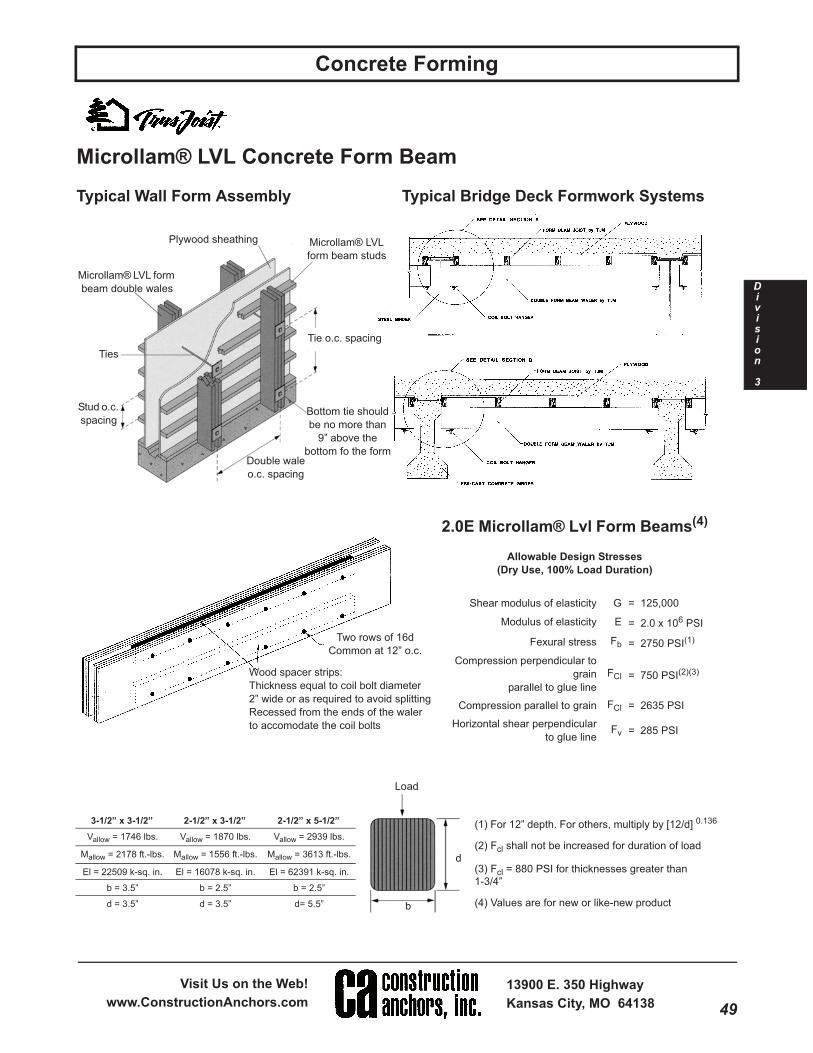
Unit # 5005001Microllam® LVL Concrete Form Beam
Typical Wall Form Assembly Typical Bridge Deck Formwork Systems
2.0E Microllam® Lvl Form Beams(4)
Allowable Design Stresses
(Dry Use, 100% Load Duration)
Shear modulus of elasticity G = 125,000
Modulus of elasticity E = 2.0 x 10⁶ PSI
Fexural stress Fb = 2750 PSI(1)
Compression perpendicular to
grain
parallel to glue line
FCl = 750 PSI(2)(3)
Compression parallel to grain FCl = 2635 PSI
Horizontal shear perpendicular
to glue lineFv = 285 PSI
Tie o.c. spacing
Microllam® LVL
form beam studs
Plywood sheathing
Microllam® LVL form
beam double wales
Ties
Stud o.c.
spacing
Double wale
o.c. spacing
Bottom tie should
be no more than
9” above the
bottom fo the form
Two rows of 16d
Common at 12” o.c.
Wood spacer strips:
Thickness equal to coil bolt diameter
2” wide or as required to avoid splitting
Recessed from the ends of the waler
to accomodate the coil bolts
d
b
Load
3-1/2” x 3-1/2” 2-1/2” x 3-1/2” 2-1/2” x 5-1/2”
Vallow = 1746 lbs. Vallow = 1870 lbs. Vallow = 2939 lbs.
Mallow = 2178 ft.-lbs. Mallow = 1556 ft.-lbs. Mallow = 3613 ft.-lbs.
El = 22509 k-sq. in. El = 16078 k-sq. in. El = 62391 k-sq. in.
b = 3.5” b = 2.5” b = 2.5”
d = 3.5” d = 3.5” d= 5.5”
(1) For 12” depth. For others, multiply by [12/d] 0.136
(2) Fcl shall not be increased for duration of load
(3) Fcl = 880 PSI for thicknesses greater than
1-3/4”
(4) Values are for new or like-new product

50
Concrete Forming
TOLL FREE 800-892-7224
800-821-7735
LOCAL 816-525-3640
FAX 816-525-4533
Division
3
Unit # 5007001Concrete Forming
Stay-Form is manufacturedfrom hot-dipped galvanizedsheet steel.
26 ga. Standard Grade25 ga. Heavy GradeSheet Size 27” x 97”
• Reduces labor cost in difficult forming applications. • Easy formulation to fit curvatures.• Joint scrabbling is eliminated in most cases. • Reduces grade removal for below-ground use.• Eighty percent labor savings in stripping. • Cut to size in multiples with power saw using• Easy rebar and service conduit penetration. abrasive blades.• Continuous placement of rebar. • Does not require special formulation of concrete.• Visual inspection of the pour.
Forming Blind-Side Walls Forming Pile Caps

51
Visit Us on the Web!
www.ConstructionAnchors.com
13900 E. 350 Highway
Kansas City, MO 64138
Division
3
Concrete Forming
Unit #5026001Sonotube Fibre Forms
Sonotube Fibre Form “A” CoatedThe original form, made from many layers of tough, high-quality firbre spirally woundand laminated with a water resistant adhesives.
Produces a column with spiral seams.
Seamless SonotubeA mid grade form with a specially finished inner ply.
Minimizes but does not completely eliminate the spiral seam appearance.
Sonotube PlusFitted with a plastic liner that imparts a smoother architectural finish to roundcolumns.
One vertical seam on columns up to 24 inch diameter and only 2 vertical seams orcolumns over 24 inch diameter.
Premium Sonotube Fibre FormsThis is a new product that is uniquely designed and coated inside.
Virtually eliminates the spiral seams and ridges.
PlacingA tremie pipe should be used in the pouring operation.National average pour rate is 15 feet per hour, but not toexceed 3000 PSF. The concrete can be vibrated asrequired, but use care to prevent vibrator from damagingtube. A release agent must always be used with SeamlessSonotube forms and will facilitate stripping if used with “A”Coated Forms.
StrippingStrip form as soon as possible after concrete has set.Recommended time is 24 to 48 hours, and should notexceed 5 days. Use saw or knife to make vertical cuts andremove form.
Sonovoid Fibre TubesSonovoid Fibre Tubes are laminated tubular forms specifically developed to provide aneconomical means of forming voids inprecast or cast-in place concrete slabs. Typical end closures are metal up to 12 inchdiameter and wood thereafter.
BracingSonotube forms are easily brought toplumb, and only minimal bracing isrequired (brace tuve every 8 feet). Useplastic brace plates, scaffolding or lumber.
Support
Sonovoid
O.D.
Maximum
Support
Spacing
Maximum
Spacing Between
Hold Down
2.25 to 18.00 4’ O.C. 18” from end of tube, then every 4’
18.7 to 22.85 3’ O.C. 18” from end of tube, then every 3’
24.85 to 36.9 2’ O.C. 12” from end of tube, then every 2’

52
Concrete Forming
TOLL FREE 800-892-7224
800-821-7735
LOCAL 816-525-3640
FAX 816-525-4533
Division
3
Unit # 5052001Concrete Forming
An economical method for producingbeautiful concrete• Lightweight. Easy handling and placement.• Produce beautiful, clean, smooth concrete.• Easy to strip.• Are designed to be reused repeatedly.• Available on a sale or rental basis.• Weatherproof.• Units nest. Use less storage and shipping space.• Complete with bracing collar and “fast” bolts.
Sizes
Column
Diameter
Length
Up To
Approx. Wt.
Per Lineal Ft.
Approx. Vol.
of Concrete
Per Lineal Ft.
12” 20’ 9.9 lbs. .8 cu. ft.
14” 20’ 10.0 lbs. 1.0 cu. ft.
16” 20’ 11.1 lbs. 1.4 cu. ft.
18” 20’ 12.3 lbs. 1.8 cu. ft.
20” 20’ 13.1 lbs. 2.2 cu. ft.
22” 20’ 14.2 lbs. 2.6 cu. ft.
24” 20’ 15.2 lbs. 3.1 cu. ft.
26” 20’ 16.2 lbs. 3.6 cu. ft.
28” 20’ 17.3 lbs. 4.2 cu. ft.
30” 20’ 18.4 lbs. 4.9 cu. ft.
32” 20’ 19.5 lbs. 5.5 cu. ft.
34” 20’ 20.5 lbs. 6.3 cu. ft.
36” 20’ 21.5 lbs. 7.0 cu. ft.
38” 20’ 22.6 lbs. 7.9 cu. ft.
40” 20’ 23.7 lbs. 8.7 cu. ft.
42” 20’ 24.8 lbs. 9.6 cu. ft.
44” 20’ 25.8 lbs. 10.6 cu. ft.
46” 20’ 26.8 lbs. 11.5 cu. ft.
48” 20’ 27.9 lbs. 12.6 cu. ft.
One-Piece Round Column Forms

53
Visit Us on the Web!
www.ConstructionAnchors.com
13900 E. 350 Highway
Kansas City, MO 64138
Division
3
Concrete Forming
Unit # 5053001Concrete Forming
Deslauriers heavy-duty steel column forms develop an exceptionally smooth, hard surface remarkably freeof voids and with a minimum number of indistinct seams.
• All standard column diameters from 14” to 60”.
• Standard column lengths are 8’ 0”, 4’ 0”, 2’ 0” and 1’ 0”.
• You can eliminate form inventory and keep working capital available by leasing Deslauriers heavy-dutyforms when needed.
• FORM DESIGN 3000 PSF ON FORMS THROUGH 36” DIAMETER OR 2000 PSF ON FORMS OVER 36”DIAMETER.
Forms are galvanized constant radius steel half round sections and quarter round sections (for forms over48” in diameter) bolted into units for crane handling on the jobsite. Each component is framed with flangeangles die-cut and punched for accurate flush butt joints without protrusion on the contact surface. Verticaland horizontal seams, opened and closed with each pour, are connected with high-speed bolts to speed set-ting and stripping. Curing time permitting, one column per form can be produced each working day.
LATERAL PRESSURE SHOULD NOT EXCEED 3000 PSFON FORMS THROUGH 36” DIAMETER OR 2000 PSF
ON FORMS OVER 36” DIAMETER
Maximum rate of pour is based on ACI SP-4 4th edition.
Deslauriers’ Adapter Bar
Temperature Ft. Per Hour
°F F2000PSF F3000PSF
40 8 13
50 10 16
60 12 20
70 14 24
80 16 26
90 18 30
Heavy-Duty Steel Column Form
54
Concrete Forming
TOLL FREE 800-892-7224
800-821-7735
LOCAL 816-525-3640
FAX 816-525-4533
Division
3
Unit # 5013002
Concrete Forming
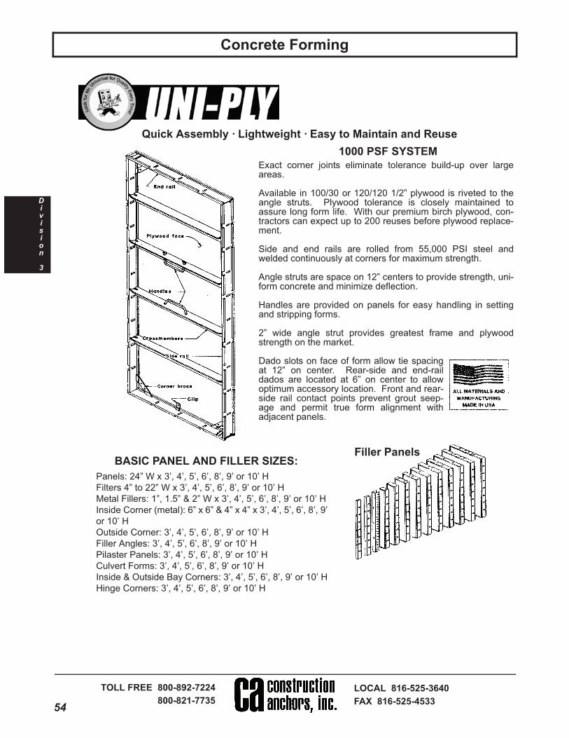
Exact corner joints eliminate tolerance build-up over largeareas.
Available in 100/30 or 120/120 1/2” plywood is riveted to theangle struts. Plywood tolerance is closely maintained toassure long form life. With our premium birch plywood, con-tractors can expect up to 200 reuses before plywood replace-ment.
Side and end rails are rolled from 55,000 PSI steel andwelded continuously at corners for maximum strength.
Angle struts are space on 12” centers to provide strength, uni-form concrete and minimize deflection.
Handles are provided on panels for easy handling in settingand stripping forms.
2” wide angle strut provides greatest frame and plywoodstrength on the market.
Dado slots on face of form allow tie spacingat 12” on center. Rear-side and end-raildados are located at 6” on center to allowoptimum accessory location. Front and rear-side rail contact points prevent grout seep-age and permit true form alignment withadjacent panels.
1000 PSF SYSTEM
BASIC PANEL AND FILLER SIZES:
Panels: 24” W x 3’, 4’, 5’, 6’, 8’, 9’ or 10’ H
Filters 4” to 22” W x 3’, 4’, 5’, 6’, 8’, 9’ or 10’ H
Metal Fillers: 1”, 1.5” & 2” W x 3’, 4’, 5’, 6’, 8’, 9’ or 10’ H
Inside Corner (metal): 6” x 6” & 4” x 4” x 3’, 4’, 5’, 6’, 8’, 9’
or 10’ H
Outside Corner: 3’, 4’, 5’, 6’, 8’, 9’ or 10’ H
Filler Angles: 3’, 4’, 5’, 6’, 8’, 9’ or 10’ H
Pilaster Panels: 3’, 4’, 5’, 6’, 8’, 9’ or 10’ H
Culvert Forms: 3’, 4’, 5’, 6’, 8’, 9’ or 10’ H
Inside & Outside Bay Corners: 3’, 4’, 5’, 6’, 8’, 9’ or 10’ H
Hinge Corners: 3’, 4’, 5’, 6’, 8’, 9’ or 10’ H
Quick Assembly · Lightweight · Easy to Maintain and Reuse
Filler Panels

55
Visit Us on the Web!
www.ConstructionAnchors.com
13900 E. 350 Highway
Kansas City, MO 64138
Division
3
Concrete Forming
Unit # 5013001
Concrete Forming
“Z” TIE HOLDER
This Scaffold bracket is designed forworker access only and has a rating of500 lbs. The maximum spacing is 8 ft.on center.
LOOP TIE – STANDARD & HEAVY DUTY
SCAFFOLD BRACKETS
LONG
Waler Plate
PLY-LAG WALER TIE
GANG LOOP TIE – STD. & HEAVY DUTY
Safety Factor 2:1
Capacity Wire Size SWL (lbs.)
STD. .225 2550
HD .243 3000
Also available with 1” x 1” plastic cone
“X” FLAT TIES
Safety Factor 2:1
Capacity SWL (lbs.)
STD. 3000
HD 3375
GANG FORM BOLT
WEDGE BOLTS

56
Concrete Forming
TOLL FREE 800-892-7224
800-821-7735
LOCAL 816-525-3640
FAX 816-525-4533
Division
3
Unit # 5004001
Concrete Forming
Fiberglass Formtie Systems
Light (6000 lbs.) and Medium (15,000 lbs.) Systems
Saves Labor! Cuts Cost in a Snap! Provides Superior Finishes!
Rod, Gripper and Wedge – The basic components of the Light (6000lbs.) and Medium (15,000 lbs.) SuperTie Systems.
Setup1. Cut fiberglass rod to length required, using abrasive blade in a cir-cular saw. Length of rod is width of structure (a) plus width of forms(b + b2) plus 16 inches (c1 + c2). Use 18” for Medium system.
The SuperTie Fiberglass Formtie Systems are usedto secure concrete formwork during concrete place-ment and initial hydrations with a formtie systemwhich would not have the inherent limitations ofpreviously popular steel formtie systems. TheSuperTie Systems eliminate the possibility of ruststains and deterioration of the structure that is oftencaused by failure of patching for steel formtie holes.
The SuperTie Systems are appropriate for use in allforming applications, but are especially beneficial insituations such as architectural finishes, since anaesthetically pleasing finish is attained with tremen-dously reduced labor expenditures. It also reducescosts in battered wall and “odd sized” tie situations,since the rod is cut to the length required at the jobsite.
Table 1 – Typical Spacing/Placement Rates
Note: It is the responsibility of the contractor to control concrete mix design and concrete placement to assure that the maximum allowable form and form tie design loads are not exceeded.
SuperTie has an ultimate tensile strength of 6000 lbs.; the ACI’s recommended 2:1 safety factor advises safe working load of 3000 lbs. SuperTie XV has an ultimate tensile strength of 15,000 pounds, swl is 750 lbs. at 2:1.
Tie Spacing Data
Rate of Placement
at Concrete Temp.
Form
Pressure
Actual Load
On Tie
Horiz. Vert. Area 40° 60° 80° lbs/sq.ft. Lbs.
Light – 6,000 Lbs. Ultimate Tensile Strength System
16” 16” 1.78ft.2 6’9” 10’ 10’ 1685 3000
24” 12” 2.00ft.2 6’ 10’ 10’ 1500 3000
24” 16” 2.67ft.2 4’4” 6’6” 10’ 1123 3000
24” 24” 4.00ft.2 2’8” 4’ 6’4” 750 3000
Medium – 15,000 Lbs. Ultimate Tensile Strength System
30” 24” 5.00ft.2 6’ 10’ 10’ 1500 7500
30” 30” 6.25ft.2 4’8” 7’ 10’ 1200 7500
30” 36” 7.50ft.2 3’9” 5’8” 9’ 1000 7500
30” 36” 9.00ft.2 3’ 4’6” 6’ 833 7500

57
Visit Us on the Web!
www.ConstructionAnchors.com
13900 E. 350 Highway
Kansas City, MO 64138
Division
3
Concrete Forming
Concrete Forming
Fiberglass Formtie Systems
Heavy (50,000 lbs.) Systems
Length of rod equals width of structure (a), plus width of forms
(b), plus 12” for the Grippers (c). Add an additional 6 inches to
one side if JD50K Jacking Device is to be used.
Supertie 50K, a 50,000 lbs (ultimate tensile strength)
system, mounted on commercially available form.
Mounting of Gripper on battered wall form
(with Grippers mounted horizontal).
Use one shim for each 3 ° of batter.
Turn clockwise to engage locking
mechanism using a “cheater bar” to
apply 125 to 200 ft. lbs. of force to the
Force Tube (“good and snug”).
Note: The Base Plate must be
securely attached to the formwork. As
concrete is placed, the Force Tubes
will become loose. Do not re-tighten.4.5 – Synopsis of Certified Testing
Meets requirements of ACI 303, 347 and 350.
Test Results
Rod
Dia. In.
Average
Load Lbs.
Elongation
%
Failure
Mode
Average
Load Lbs.
Failure
Mode
.308 7053 0.06 Tensile 3720 Shear
.500 15,590 0.09 Tensile 6700 Shear
1.0 53,193 0.08 Tensile 28,700 Shear
4.5.1 – Tensile, Shear and ElongationTesting Agency – Smith-Emery Company, Los Angeles,CaliforniaTesting Agency – Twining Laboratories, Long Beach,CaliforniaTesting Criteria – ACI 347, Formwork for ConcreteTest Stand – Insitu tensile testing of the SuperTie 6000lbs. ultimate strength system was performed utilizing astandard configuration wood form system consisting of3/4” sheathing with 2” x 4” strongbacks and wales, andSuperTie Grippers and Wedges. The SuperTie 15,000and 50,000 lbs. ultimate strength systems were tested uti-lizing steel plates and SuperTie XV and SuperTie 50KGrippers. Both systems were loaded axially utilizing acalibrated universal testing machine. Shear testing wasperformed utilizing a fixture to develop single shear.

58
Concrete Forming
TOLL FREE 800-892-7224
800-821-7735
LOCAL 816-525-3640
FAX 816-525-4533
Division
3
Concrete Forming
Cam-Lock Forming System
Uses flexible, inexpensiveforming materials.S4S – 2” x 4”s with 4’ x 8’ x3/4” plywood sheets.
All new Gates
scaffold brackets
factory tested to
3,000 lbs.
Cam BracketStiff-Back Cam
1” dia. cushion cone.1” break back, self-centering tapered cone for13/16” hole.

59
Visit Us on the Web!
www.ConstructionAnchors.com
13900 E. 350 Highway
Kansas City, MO 64138
Division
3
Concrete Forming
Unit # 5006003Unit # 5006003Concrete Forming
Anchor-Lock Forming System
Gates regular anchor-lock #3
tie with plastic cones.
Gates anchor-lock #5 tie with
cones molded in place.
2” x 3” and 2” x 2” x 3/16” angles are bolted with flat-head bolts at each end of the gang form. The anglesare then locked together with U-clamps for verticalalignment of the two gang forms.
U-Clamp
Flat Head Bolts
5/16” x 3” 3/8” x 6-1/2”3/8” x 5-1/2” 3/8” x 8-1/2”
Gates Pick-Up Loops mustalways be used with Exten-sion straps (A) and securedwith three bolts (B,C,D) asshown at right.
Designed working load not toexceed 2,000 lbs., with athree-to-one safety factor.
The Gates anchor-lock #5 system uses 3/4” ply-wood with the 2 x 6 flat walers on 12” centers,crossed by 4 x 4s on 24” centers to minimize theunsupported plywood span. Gates anchor-locksare spaced 24” x 24” (4 sq. ft. per tie.)
The Gates regular anchor-lock #3 system uses 3/4”plywood with 2 x 6 flat walers on 16” centers, crossedby 4 x 4 stiffbacks on 4’-0” to 8’-0” centers dependingon height of gang form. Gates anchor-locks arespaced 24” along the 2 x 6 walers making a tie spac-ing of 24” x 16” (2-2/3 sq. ft. per tie).
Advantages of Gang Forming• Lower Construction Costs• No Loose Hardware• Gang Form Both Sides• Pass-Thru Form Ties
#3 Forming System #5 Forming System

60
Concrete Forming
TOLL FREE 800-892-7224
800-821-7735
LOCAL 816-525-3640
FAX 816-525-4533
Division
3
nit # 5006004
#9 Anchor-Lock Gang Forming
The standard Gates #9 Anchor-LockGang Form is made up of four mainparts:1. 4 x 8 x 3/4” BB grade or plastic-faced plywood panels
2. Horizontal 4 x 4 walers on 12”centers
3. Double 4 x 4 strongbacks 1 ft.from each end and then on approxi-mately 3-ft. centers
4. Gates’ heavy-duty #9 Anchor-Lock hardware.
By spacing the Anchor-Locks 3-ft.along the vertical strongbacks, a tiepattern of approximately 3 ft. x 3 ft. isobtained. Multiple holes in the faceof the Anchor-Lock plate allow foreasy lock alignment over the tieholes with lag screws.
Strongback and tie spacingscan be adjusted to fit jobrequirements, but nevershould a lock and tie sup-port more than 9 sq. ft. ofform.
Tie Combinations#9 Saddle-Lock
& Perforated Box Tube

61
Visit Us on the Web!
www.ConstructionAnchors.com
13900 E. 350 Highway
Kansas City, MO 64138
Division
3
Concrete Forming
Unit # 5006007
Steel Frame Gang Form Adapter
Now you can gang form yoursteel frame panels just as theyare with Gates box-tube adapter,with all locks attached.
2 Locks on 8’-0” Tubes
Isometric of strong-back and steel frame form

62
Concrete Forming
TOLL FREE 800-892-7224
800-821-7735
LOCAL 816-525-3640
FAX 816-525-4533
Division
3
Unit # 5006005
Lok-Fast Column Clamp
• Can be job-built• Gang formed• Minimum labor costs• Designed for rapid placement of concrete• Rapid locking action• No loose pieces

63
Visit Us on the Web!
www.ConstructionAnchors.com
13900 E. 350 Highway
Kansas City, MO 64138
Division
3
Concrete Forming
Unit # 5006008
Retractable Inside Corner
Gates Retractable Aluminum I.S. CornerFor elevator or stair gang form use, pro-vides 5/8” clearance on each side at allfour corners. To retract, loosen all boltson vertical cross bars spaced on 24”centers using a speed wrench. Rotateturnbuckles in unison, drawing formsaway from concrete walls. Lift gangforms and reset.
NEW – Pin’N Lock Outside Corner
You can have leakproof cor-ners using Gates adjustablePin’N Lock heavy duty, out-side steel corners with noloose parts.
• Tight Outside Corners
• No Loose Parts
• Adjustable Locking Pin
• Fast, Easy to Use

64
Concrete Forming
TOLL FREE 800-892-7224
800-821-7735
LOCAL 816-525-3640
FAX 816-525-4533
Division
3
Unit # 5006006
Lift’N Lock Safety Platform
Scaffold Brackets
3’-0” Scaffold Bracket

65
Visit Us on the Web!
www.ConstructionAnchors.com
13900 E. 350 Highway
Kansas City, MO 64138
Division
3
Concrete Forming
Unit # 5006001
Radius Wall Forming
Suggested Cam-Lock Radius Forming Details Suggested #5 Anchor-Lock Forming Details
Educated Radius Walers
Suggested #9 Anchor-Lock Forming Details
Plywood Bending
20’-0” Dim. 3 Pieces 1/4”
30’-0” Dim. 2 Pieces 3/8”
40’-0” Dim. 2 Pieces 3/8”
50’-0” Dim. 1 Piece 5/8”
60’-0” Dim. 1 Piece 3/4”
And LargerPrebending Plywood Panels

66
Concrete Forming
TOLL FREE 800-892-7224
800-821-7735
LOCAL 816-525-3640
FAX 816-525-4533
Division
3
Unit # 5011016Concrete Forming Basic Pressure FormulasWall Pours
CONCRETE PRESSUREGENERAL NOMENCLATURE
P = Lateral Pressure (PSF)
R = Rate of Placement(feet per hour)
T = Ambient Temperature,unless controlled (degrees F).See note 2.
h = Height of Fresh Concreteabove specified point of inter-est (feet).
General Formula:
P = 150 9,000R
(Maximum “P” value 2,000 PSF, mini-mum 600 PSF, in no case greaterthan 150h). See note 2.
Modified Formula:
P = 150 + 43,400 + 2,800R
(Maximum “P” value 2,000 PSF, mini-mum 600 PSF, in no case greaterthan 150h). See note 2.
T T
T
Notes:1. The background and referencefor these equations and restrictionsmay be found in “RecommendedPractice for Concrete Formwork”,American Concrete Institute (ACI),Standard 347R-88.
2. The 150 used in the formulas ispounds per cubic foot, the recog-nized concrete weight for formworkdesign.
3. All uncontrolled placementsfaster than 7’-0” per hour and con-trolled wall pours exceeding 10’-0”per hour with 4’-0” or less layeredplacements should be analyzed perfull liquid head, 150h.
Snap Ties
A-2 Plastic Cone Selection Chart
Diameter Length
3/4” 1”, 1-1/2”
1” 1”, 1-1/2”
1-1/4” 1-1/2”, 2”
Omni WedgePlastic Cones
Standard End Dimensions4-3/4” Short Ends8-1/4” Long Ends
Special End Dimensions Available.
Standard Snap Tie2,250 Lbs.
Safe Working Load
Heavy Snap Tie3,350 Lbs.
Safe Working Load
Washer Type
Cone Type
67
Visit Us on the Web!
www.ConstructionAnchors.com
13900 E. 350 Highway
Kansas City, MO 64138
Division
3
Concrete Forming
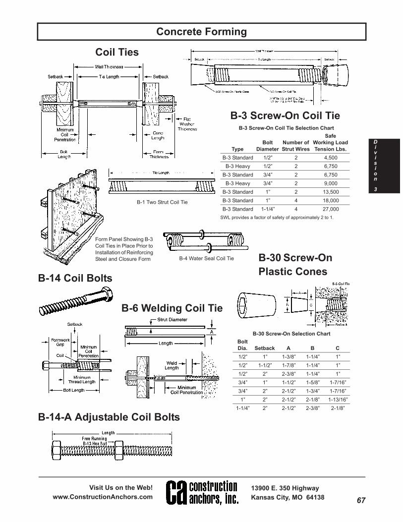
Unit # 5011011Concrete Forming Coil Ties
B-3 Screw-On Coil Tie Selection Chart
SWL provides a factor of safety of approximately 2 to 1.
Type
Bolt
Diameter
Number of
Strut Wires
Safe
Working Load
Tension Lbs.
B-3 Standard 1/2” 2 4,500
B-3 Heavy 1/2” 2 6,750
B-3 Standard 3/4” 2 6,750
B-3 Heavy 3/4” 2 9,000
B-3 Standard 1” 2 13,500
B-3 Standard 1” 4 18,000
B-3 Standard 1-1/4” 4 27,000
B-3 Screw-On Coil Tie
Form Panel Showing B-3
Coil Ties in Place Prior to
Installation of Reinforcing
Steel and Closure Form
B-1 Two Strut Coil Tie
B-4 Water Seal Coil Tie
B-14 Coil Bolts
B-14-A Adjustable Coil Bolts
B-6 Welding Coil Tie
B-30 Screw-On
Plastic Cones
B-30 Screw-On Selection Chart
Bolt
Dia. Setback A B C
1/2” 1” 1-3/8” 1-1/4” 1”
1/2” 1-1/2” 1-7/8” 1-1/4” 1”
1/2” 2” 2-3/8” 1-1/4” 1”
3/4” 1” 1-1/2” 1-5/8” 1-7/16”
3/4” 2” 2-1/2” 1-3/4” 1-7/16”
1” 2” 2-1/2” 2-1/8” 1-13/16”
1-1/4” 2” 2-1/2” 2-3/8” 2-1/8”

68
Concrete Forming
TOLL FREE 800-892-7224
800-821-7735
LOCAL 816-525-3640
FAX 816-525-4533
Division
3
D-2 and D-3 She-Bolt Selection Chart
Safe
Working Load
She-Bolt
External Thread
Inside
Tie Rod Thread
External
Hardware
Type Tension Lbs. Dia. Type Dia. Type A B C D E L Required
D-2 9,000 3/4” Acme 1/2” NC 5/8” 1/2” 1-1/4” 3/4” 3” 20” 3/4” Dia. D-6
D-30 9,000 7/8” Coil 1/2” Coil 1” 1/2” 1-1/2” 7/8” 2-3/4” 18”, 20”, 24”7/8” Dia.
B-27 or B-39
D-30 12,000 7/8” Coil 5/8” Coil 1” 1/2” 1-1/2” 7/8” 2-3/4” 18”, 20”, 24” 7/8” Dia. B-39
D-30 18,000 1-1/4” Coil 3/4” Coil 1” 3/4” 2” 1-1/4” 4” 20”, 24”, 30”, 35” 1-1/4” Dia. B-39
D-30 37,500 1-1/2” Coil 1” Coil 1” 3/4” 2” 1-1/2” 4” 20”, 24”, 30”, 35” 1-1/2” Dia. B-39
D-30 HS 56,000 1-1/2” Coil 1-1/4” Coil 1” 3/4” 2-3/4” 1-3/4” 4” 20”, 24”, 30”, 35” 1-1/2” Dia. B-39
Unit # 5011013Concrete Forming
D-9 Taper Ties Selection Chart
SWL provides a factor of safety of approximately 2 to 1.
Safe Working Large End of Tie Small End of Tie
Load Tension
Lbs.
Coil
Thread Dia.
Length
of Thread
Coil
Thread Dia.
Length
of Thread
Standard
Tie Lengths
Tapered
Body Dia.
7,500 3/4” 10” 1/2” 2” 34”, 43”, 52” .670” to .500”
18,000 1” 10” 3/4” 6” 30”, 36”,
42”, 48”,
54”, 60”, 72”
.884” to .750”
34,000 1-1/4” 10” 1” 6” 1.113” to 1.00”
50,000 1-1/2” 10” 1-1/4” 6” 1-1/2” to 1-1/4”
75,000 1-3/4” 10” 1-1/2” 6”36”, 48”,
60”, 72”1-3/4” to 1-1/2”
D-9 Taper Ties
D-2 and D-30 She-Bolts
D-1 and D-18
Inside Tie Rods
D-33 Waterseal Washer
B-32 Handle Coil Nut B-27 Nut Washer B-39 Wing Nut
69
Visit Us on the Web!
www.ConstructionAnchors.com
13900 E. 350 Highway
Kansas City, MO 64138
Division
3
Concrete Forming
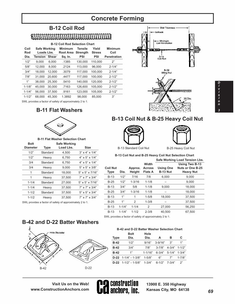
Unit # 5011012Concrete Forming B-12 Coil Rod
B-13 Standard Coil Nut B-25 Heavy Coil Nut
D-22B-42
B-42 and D-22 Batter Washer Selection Chart
Type
Bolt
Dia.
Hole
Dia. A B C
B-42 1/2” 9/16” 3-9/16” 3” 1”
B-42 3/4” 7/8” 3-7/8” 4-3/4” 1-1/2”
B-42 1” 1-1/16” 6-3/4” 5-1/4” 1-3/4”
D-22 1-1/4” - 1-3/8” 1-5/8” 6” 7” 1-7/8”
D-22 1-1/2” - 1-5/8” 1-3/4” 6-1/2” 7-3/4” 2”
B-13 Coil Nut and B-25 Heavy Coil Nut Selection Chart
SWL provides a factor of safety of approximately 2 to 1.
Safe Working Load Tension Lbs.
Coil Nut
Type Dia.
Approx.
Height
Width
Across
Flats A
Using One
B-13 Nut
Using Two B-13
Nuts or One B-25
Heavy Nut
B-13 1/2” 7/16 7/8 6,000 9,000
B-25 1/2” 1-3/16 1-1/8 – 9,000
B-13 3/4” 5/8 1-1/8 9,000 18,000
B-25 3/4” 1-3/16 1-1/8 – 18,000
B-13 1” 1 1-5/8 18,000 37,500
B-25 1” 2 1-3/8 – 37,500
B-13 1-1/4” 1-1/4 2 27,000 56,250
B-13 1-1/4” 1-1/2 2-3/8 40,500 67,500
B-13 Coil Nut & B-25 Heavy Coil Nut
B-11 Flat Washers
B-12 Coil Rod Selection Chart
SWL provides a factor of safety of approximately 2 to 1.
Coil
Rod
Safe Working
Loads Lbs.
Minimum
Root Area
Tensile
Strength
Yield
Stress
Minimum
Coil
Dia. Tension Shear Sq. In. PSI PSI Penetration
1/2” 9,000 6,000 .1385 130,000 110,000 2”
5/8” 12,000 8,000 .2124 113,000 96,000 2-1/4”
3/4” 18,000 12,000 .3079 117,000 100,000 2-1/4”
7/8” 31,000 20,600 .4477 117,000 100,000 2-1/2”
1” 38,000 25,300 .5410 140,000 120,000 2-1/2”
1-1/8” 45,000 30,000 .7163 126,600 105,000 2-1/2”
1-1/4” 56,000 37,500 .9161 123,000 105,000 2-1/2”
1-1/2” 68,000 45,300 1.3892 98,000 85,000 3”
B-11 Flat Washer Selection Chart
SWL provides a factor of safety of approximately 2 to 1.
Bolt
Diameter Type
Safe Working
Load Lbs. Size
1/2” Standard 4,500 3” x 4” x 1/4”
1/2” Heavy 6,750 4” x 5” x 1/4”
3/4 Standard 6,750 4” x 5” x 1/4”
3/4 Heavy 9,000 5” x 5” x 3/8”
1 Standard 18,000 5” x 5” x 7/16”
1 Heavy 37,500 7” x 7” x 3/4”
1-1/4 Standard 27,000 5” x 5” x 7/16”
1-1/4 Heavy 37,500 7” x 7” x 3/4”
1-1/2 Standard 37,500 5” x 5” x 3/4”
1-1/2 Heavy 37,500 7” x 7” x 3/4”
B-42 and D-22 Batter Washers

70
Concrete Forming
TOLL FREE 800-892-7224
800-821-7735
LOCAL 816-525-3640
FAX 816-525-4533
Division
3
nit # 5011010oncrete Forming
B-18 Single Flared Coil Insert B-33 Double Flared Criss Cross
Coil Loop Insert
F-56 Expanded Coil Insert
for Coil Threaded Bolts
Coil Loop ProtectorsInstall Coil Inserts.
Provide Setback.
For 1/2”, 3/4”, 1” Dia. Inserts
B-31 Rock Anchor
B-31 Rock Anchor Selection Chart
SWL provides a factor of safety of approximately 2 to 1.
Coil Rod
Diameter
Min. Hole
Depth “L”
Req. Hole
Dia. “D”
Safe Working
Load Tension
Lbs.
1/2” 6” 1-3/8” 4,500
3/4” 8” 1-5/8” 9,000
1” 10” 1-3/4” 18,000
B-16 Coil Loop Insert
Selection Chart
SWL provides a factor of safety of approximately 2 to 1.
SWL may vary with concrete weight and strength, as well as with insert setback and edge distance. Contact the Dayton/Richmond Technical Service Department for variables.
Bolt
Diameter
Insert
Length
Wire Strut
Diameter
Safe Working
Load Tension Lbs.
Minimum
Concrete
Strength PSI
1/2” 3” .223 4,500 2,000
1/2” 4” .223 4,500 2,000
1/2” 6” .306 7,500 2,000
3/4” 4” .223 4,500 2,000
3/4” 6” .306 7,500 2,000
1” 6” .306 7,500 2,000
1” 8” .306 7,500 2,000
B-16 Coil Loop Insert Straight

71
Visit Us on the Web!
www.ConstructionAnchors.com
13900 E. 350 Highway
Kansas City, MO 64138
Division
3
Concrete Forming
nit # 5011014ncrete Forming D-12 and D-12-S Rod Clamps
A-90 Scaffold Bracket Jack
A-27 and A-27-M Turnbuckle Form Aligners
D-12 Form Clamp
Rod Size
Approx. Safe
Working Load
1/4” 1,250
3/8” 3,000
1/2” 5,000
5/8” 7,500
D-14Tightening
Wrench
Coils or Straight
Pencil Rod
D-12 and D-12-S Rod Clamp Selection Chart
Type
Rod
Diameter
Safe Working Load
Tension Lbs.
D-12 1/4” 1,125
D-12-S 1/4” 1,125
D-12 3/8” 2,250
D-12-S 3/8” 2,250
D-12 1/2” 3,750