Embed Size (px)
Citation preview

EMC-C95-LB-1/04-UK
ISO CylinderLarge Bore Size Type
ø125, ø160, ø200, ø250
Series C95

2

ISO/VDMA Cylinder: Large Bore Size TypeDouble Acting, Single Rod
Series C95ø125, ø160, ø200, ø250
How to Order
C95SDBuilt-in magnet
Bore sizeStroke (mm)
125160200250
125 mm160 mm200 mm250 mm
Mounting styleBLFGCDT
Basic/without bracket styleAxial foot style
Rod side flange styleHead side flange style
Single clevis styleDouble clevis style
Center trunnion style
B 100 Number ofauto switches
Auto switchNil Without auto switch
A53
C95S B 125
125
100
NilS3n
2 pcs.1 pc.3 pcs.
“n” pcs.
S
Refer to “Standard Stroke” on page 5.
∗ For the applicable auto switch model, refer to the table below.
Mounting Bracket Part No.
Foot (1)
FlangeSingle clevisDouble clevis
125L5125F5125C5125D5125
160L5160F5160C5160D5160
200L5200F5200C5200D5200
250L5250F5250C5250D5250
Auto Switch Mounting Bracket Part No.
D-A3/A4/K3/G3D-A5/A6/F5/J5D-Z�/Y�
125BS1-125
BT-08BA4-080
160BS1-160
BT-16BS4-160
200BS1-200
BT-16BS4-160
250—
BT-20—
Bore size (mm) Bore size (mm)
With auto switch
Without auto switch
Note 1) Two foot brackets and mounting bolts (4 pieces) are included in this no. (ø125 to ø250)
Note 2) Accessories for mounting brackets are as followsFoot, Flange, Single clevis: Mounting boltsDouble clevis : Clevis pin, Retaining rings, Mounting bolts
∗ Lead wire length symbols: 0.5 m ········· Nil (Example) A533 m ········· L (Example) A53L5 m ········· Z (Example) A53Z
�: Manufactured upon receipt of order.Note) Switch can not be mounted on ø250 Refer to page 12 for details of applicable auto switches in addition to those listed above.
Applicable Auto Switch/Tie-rod MountingWiring
(Output)Tie-rod
mountingBand
mounting0.5(Nil)
3(L)
5(Z)
—
—
NoPLC
A56
A53A54A67A64
A59WZ76Z73Z80———
F59F5PJ51J59
F59WF5PWJ59W
F5BAL
F59FY59AY59BY7P
Y7NWY7PWY7BWY7BAL
——
�
��������———�������—
�������———
�
��������———��������
��������——
—
��————�————��������
��������——
—
————————
A33A34A44——————
——
F5NTL — � �—————————
G39K39
Relay, PLCNote)
Note)
Note)
Note)
Note)
Relay, PLC
Relay, PLC
Yes
Lead wire length (m)Auto switch model
DC
Load voltageApplicable load
Relay, PLC
Type Special function
Yes
Yes
No
Indi
cato
r lig
ht
Ree
d sw
itch
Relay, PLC
Yes
AC
—
—100 V, 200 V
—200 V or less
——
AC 100100 V or less
—
100 V, 200 V
—
100 V, 200 V
—
IC
IC
IC—IC
—
IC
—
IC
—
—
—
IC
IC—
IC—
IC
—
—
—
—
24 V
24 V
24 V
24 V
Sol
id s
tate
sw
itch
3-wire(Equiv. to NPN)
3-wire
3-wire (NPN)3-wire (PNP)
3-wire (NPN)3-wire (PNP)
4-wire (NPN)3-wire (NPN)
3-wire (NPN)2-wire
3-wire (PNP)3-wire (NPN)3-wire (PNP)
3-wire (NPN)2-wire
2-wire
2-wire
2-wire
2-wire
2-wire
5 V
5 V, 12 V12 V—5 V12 V
5 V, 12 V
—12 V
5 V, 12 V
5 V, 12 V12 V
5 V, 12 V12 V
5 V, 12 V
12 V
5 V, 12 V
5 V, 12 V
12 V
12 V
12 V
DIN terminal
Grommet
Electricalentry
Grommet
Terminalconduit
Terminalconduit
Diagnostic indication (2-color)
Water resistant (2-color)With timer
Diagnostic output (2-color)
Water resistant (2-color)
—
—
—
—
Diagnostic indication(2-color)
—
Diagnostic indication(2-color)
3

Mounting Accessory, Cylinder
Mounting Accessory, Rod
Boresize
(mm)
125
160
200
250
Boresize
(mm)
125
160
200
250
Boresize
(mm)
125
160
200
250
Without lock
F5125
F5160
F5200
F5250
See page 8 for dimensions.
D5125
D5160
D5200
D5250
See page 8 for dimensions
C5125
C5160
C5200
C5250
See page 9 for dimensions.
L5125
L5160
L5200
L5250
See page 8 for dimensions.
GKM30-54
GKM35-54
GKM35-54
GKM40-84
See page 10 for dimensions.
KJ27D
KJ36D
KJ36D
KJ42D
See page 10 for dimensions.
JA125-27-200
JA160-36-200
JA160-36-200
See page 10 for dimensions.
F D C
L
GKM KJ JA
Rod/Head side flange
Supplied with 4 screws
Female head side clevis(Corresponds to E accessories)
Supplied with bolt, safety deviceand 4 screws
Male head side clevis
Supplied with 4 screws
Foot
Supplied with two piecesSupplied with 4 screws
Rod clevisISO 8140
Piston rod ball jointISO 8139
Floating joint
Supplied with bolts and safety devices
Accessory
Series C95
4
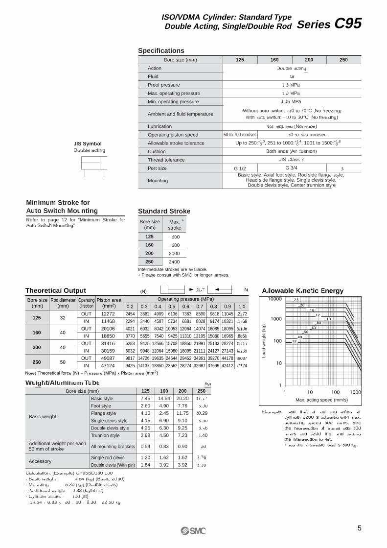
Specifications
Action
Fluid
Proof pressure
Max. operating pressure
Min. operating pressure
Ambient and fluid temperature
Lubrication
Operating piston speed
Allowable stroke tolerance
Cushion
Thread tolerance
Port size
Mounting
125
G 1/2
200 250
G 1
160
Double acting
Air
1.5 MPa
1.0 MPa
0.05 MPa
Without auto switch: –10 to 70°C (No freezing)With auto switch: –10 to 60°C (No freezing)
Not required (Non-lube)
50 to 700 mm/sec 50 to 500 mm/sec
Up to 250:+1.0 0 , 251 to 1000:+1.4
0 , 1001 to 1500:+1.8 0
Both ends (Air cushion)
JIS Class 2
G 3/4
Standard Stroke
125
160
200
250
Bore size(mm)
Max.stroke
1600
1600
2000
2400
Intermediate strokes are available.∗ Please consult with SMC for longer strokes.
JIS SymbolDouble acting
Minimum Stroke forAuto Switch Mounting
∗
Bore size (mm)
Refer to page 12 for “Minimum Stroke for Auto Switch Mounting”.
Basic style, Axial foot style, Rod side flange style, Head side flange style, Single clevis style, Double clevis style, Center trunnion style
Theoretical OutputBore size
(mm)
125
160
200
250
32
40
40
50
OUT
IN
OUT
IN
OUT
IN
OUT
IN
12272
11468
20106
18850
31416
30159
49087
47124
0.2 0.3 0.4 0.5 0.6 0.7 0.8 0.9 1.0Rod diameter
(mm)Operatingdirection
Piston area(mm2)
Operating pressure (MPa)
(N) OUT IN
Note) Theoretical force (N) = Pressure (MPa) x Piston area (mm2)
Allowable Kinetic Energy
Example: Load limit at rod end when air cylinder ø200 is actuated with max. actuating speed 500 mm/s. See the intersection of lateral axis 500 mm/s and ø200 line, and extend the intersection to left. Thus the allowable load is 800 kg.
2454
2294
4021
3770
6283
6032
9817
9425
3682
3440
6032
5655
9425
9048
14726
14137
4909
4587
8042
7540
12566
12064
19635
18850
6136
5734
10053
9425
15708
15080
24544
23562
7363
6881
12064
11310
18850
18095
29452
28274
8590
8028
14074
13195
21991
21111
34361
32987
9818
9174
16085
15080
25133
24127
39270
37699
11045
10321
18095
16965
28274
27143
44178
42412
12272
11468
20106
18850
31416
30159
49087
47124
Weight/Aluminum TubeBore size (mm)
Basic weight
Basic style
Foot style
Flange style
Single clevis style
Double clevis style
Trunnion style
All mounting brackets
Single rod clevis
Double clevis (With pin)
125
7.45
2.60
4.10
4.15
4.25
2.98
0.54
1.20
1.84Accessory
160
14.54
4.90
2.45
6.90
6.30
4.50
0.83
1.62
3.92
200
20.20
7.76
11.75
9.10
9.25
7.23
0.90
1.62
3.92
250
37.17
15.00
20.29
18.60
18.46
14.40
1.60
2.76
6.69
(kg)
Calculation: (Example) CP95SD160-100• Basic weight ·········· 14.54 (kg) (Basic, ø160)• Mounting ·········· 6.30 (kg) (Double clevis)• Additional weight ··· 0.83 (kg/50 st)• Cylinder stroke ······ 100 (st) 14.54 + 0.83 x 100 ÷ 50 + 6.30 = 22.50 kg
Additional weight per each 50 mm of stroke
Load
wei
ght (
kg)
Max. acting speed (mm/s)
5
Series C95ISO/VDMA Cylinder: Standard TypeDouble Acting, Single/Double Rod

Construction
Replacement Parts: Seal Kit
CS95-125CS95-160CS95-200CS95-250
125160200250
Bore size (mm) Kit no. Contents
11
2
2111
2
21
2Only ø125
Only ø125
Only ø125
18
4
ø160 to ø250Component PartsMaterial
Aluminum castedAluminum casted
Description Note
1Head coverw
q
No.Rod cover 1
Qty. Qty.Material
NBR
Urethane
NBRNBRNBRResin
NBR
Steel for springLead-bronze casted
Steel wireSteelSteel
Carbon steelRolled steelRolled steel
Aluminum alloyCarbon steel
Aluminum alloyAluminum die-castedAluminum die-casted
Description Note
1
1
1
Piston gasketMagnet ring
Cushion seal
Cylinder tube gasketRod sealPiston sealWear ring
Cushion valve seal
Snap ringBushingCushion valveRod end nutTie-rod nutTie-rodCushion ring BCushion ring A
Head cover
PistonPiston rodCylinder tube
Rod cover
111
1
6-2
6-1
No.q
w
e
r
t
u
i
o
!0
!1
!2
!3
!4
!5
!6
!7
!8
!9
@0
Kits include items !3 to !7 from the table above.
9
ø125
ø125
19
78
181012111164 26-21317145156-13
[First angle projection]
∗ Seal kits consist of items !3 to !7 contained in one kit, and can be ordered using the order number for each respective tube bore size.
Series C95
6

Dimensions: Without Mounting Bracket
125160200250
Bore size(mm)
54727284
AM
60657590
øBe11
32404050
øD
G 1/2G 3/4G 3/4G 1
EE
19303531
PL
M12 x 1.75M16 x 2M16 x 2
M20 x 2.5
RT
13151520
L12
M27 x 2M36 x 2M36 x 2M42 x 2
KK
27363646
SW
38555759
G
20272729
BG(Min.)
160180180200
L8
108
1520
VD
666
10
VA
17151820
WA
15252528
WB
658095
105
WH
285338353399
ZZ
136180220270
�E
110140175220
�R
40505565
L2
6000
L9
C95SB Bore size - Stroke
[First angle projection]
Stroke
Stroke
Port CushionValve
7
Series C95ISO/VDMA Cylinder: Standard TypeDouble Acting, Single/Double Rod

Dimensions: Cylinder Mounting Accessory
125160200250
Bore(mm)
Max. 157Max. 195Max. 238Max. 290
E1
90115135165
R
45607080
W
20202525
MF
245280300330
ZF
16182226
øFB
25303040
øCDH9
Max. 157Max. 209Max. 209Max. 249
EB
Min. 30Min. 35Min. 35Min. 45
L
275315335375
XD
130170170200
UBh14
709090
110
CBH14
709090
110
EW–0.5–1.2
Max. 26Max. 31Max. 31Max. 41
MR
90115135165
TR
Max. 25Max. 25Max. 35Max. 40
AO
89
1214.5
AT
270320345380
XA
250300320350
SA
90115135165
AH
16182226
øAB
Max. 50Max. 50Max. 50Max. 60
L1
145170185205
XV
199242257289
Z
25323240
TLh14
25323240
øTDe8
160200250320
TMh14
Max. 160Max. 220Max. 260Max. 320
UW
180230270330
TF
Max. 224Max. 280Max. 320Max. 395
UF
Max. 157Max. 195Max. 238Max. 290
E2
Foot style (L)
Rear double clevis D
Center trunnion style (T)
Mounting at the back (G)
Mounting at the front (F)
Flange style (F, G)
Head side single clevis style (C)
Head side double clevis style (D)
XV + 1/2 stroke
[First angle projection]
Stroke
Stroke
Stroke
Stroke
Series C95
8
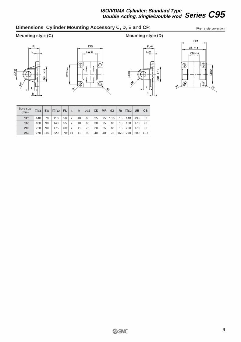
Dimensions: Cylinder Mounting Accessory C, D, E and CR
Bore size(mm) �E1 EW �TG1 FL l1 I2 ød1 CD MR d2 R1 �E2 UB CB
70 50 7 60 25 70
90 55 7 65 30 90
90 60 7 75 30 90
110 70 11 90 40 110
125
160
200
250
140
180
220
270
110
140
175
220
10
10
11
11
25
25
25
40
13.5
18
18
22
10
13
13
16.5
140
180
220
270
130
170
170
200
Mounting style (C) Mounting style (D)
[First angle projection]
9
Series C95ISO/VDMA Cylinder: Standard TypeDouble Acting, Single/Double Rod

Dimensions: Piston Rod Mounting Accessory
Piston Rod Clevis (ISO 8140)Steel, Zinc Chromate Plated
125
160/200
250
GKM30-54
GKM35-54
GKM40-84
Bore size(mm)
M27 x 2
M36 x 2
M42 x 2
Part no. e
30
35
40
+0.60+0.15+0.60+0.15+0.60+0.15
b
110
144
168
d
30
35
40
øfh11
L1max.
cmin.
amax.
Lmin.
155
201
245
54
54
84
55
70
85
45
57
77
125160/200
250
KJ27DKJ36DKJ42D
Bore size(mm)
M27 x 2M36 x 2M42 x 2
Part no. d3
303540
110125142
h
708090
d6max.
b1h12
Lmin. α L3
374349
515660
15°16°4°
355546
Piston Rod Ball Joint (ISO 8139)Steel, Zinc Chromate Plated
d1H9
[First angle projection]
Dimensions: Piston Rod Mounting Accessory
Floating Joint JASteel
Bore size (mm) M Part no. A B C øD E F G H P U Load (kN) Weight (g) Angle
41
55± 5°125
160, 200
M27 x 2
M36 x 2
JA125-27-200
JA160-36-200
123
178
34
51
66
96
13
16
24
55
20
24
24
42
2
3
28
71
1500
4700
[First angle projection]
38
55
Series C95
10

11
Series C95ISO/VDMA Cylinder: Standard TypeDouble Acting, Single/Double Rod

Series C95Auto Switch Specifications
Electrical entry (Function)
Applicable Auto SwitchType Auto switch model
Reed switch
Solid state switch
D-A5�/A6�D-A59WD-Z7�/Z80D-A3�D-A44D-F5�/J5�D-F5�W/J59WD-F5BALD-F59FD-F5NTLD-Y59�D-Y69�D-Y7PD-Y7PVD-Y7�WD-Y7�WVD-Y7BALD-G39/K39
GrommetGrommet (2-color indication)
Grommet Terminal conduit
DIN terminalGrommet
Grommet (2-color indication)Grommet (2-color indication, Water resistant)
Grommet (2-color indication, Diagnostic output)Grommet (With timer)
Grommet (In-line)Grommet (Perpendicular)
Grommet (In-line)Grommet (Perpendicular)
Grommet (2-color indication, In-line)Grommet (2-color indication, Perpendicular)
Grommet (Water resistant, In-line)Terminal conduit
Refer to Page 6-16-1 for details on auto switches.
Minimum Stroke for Auto Switch MountingSupport bracket except center trunnion Center trunnion
A5�A6�
A59W
F5�(W)/J5�/J59WF5BAL/F59F
F5NTL
A3�K3�G3�
A44
Z7�/Z80
Y59�/Y7PY7�W
Y69�/Y7PVY7�WV
Y7BAL
No. of auto switches
1, 2n
2
n
11, 2
n
1, 2
n
12 (Same side)
2 (Different sides)
n (Same side)
n (Different sides)
12 (Same side)
2 (Different sides)
n (Same side)
n (Different sides)
1, 2
n
1, 2
n
1, 2
n
1, 2
n
ø12515
15 + 55(n-2)/2n = 2, 4, 6, 8···
2020 + 55(n-2)/2 n = 2, 4, 6, 8···
2020
20 + 55(n-2)/2 n = 2, 4, 6, 8···
2525 + 55(n-2)/2 n = 2, 4, 6, 8···
1010035
100 + 100(n-2) n = 2, 3, 4, 5···35 + 30(n-2)
n = 2, 3, 4, 5···105535
55 + 55(n-2) n = 2, 3, 4, 5···35 + 30(n-2)
n = 2, 3, 4, 5···10
10 + 40(n-2)/2 n = 2, 4, 6, 8···
1010 + 40(n-2)/2 n = 2, 4, 6, 8···
1010 + 30(n-2)/2 n = 2, 4, 6, 8···
1510 + 45(n-2)/2 n = 2, 4, 6, 8···
ø16010
10 + 55(n-2)/2 n = 2, 4, 6, 8···
�
�
1510
10 + 55(n-2)/2 n = 2, 4, 6, 8···
1515 + 55(n-2)/2 n = 2, 4, 6, 8···
1010035
�
�
105535
�
�
10
�
10
�
10
�
10
�
ø20010
�
�
�
15�
�
15
�
1010035
�
�
105535
�
�
10
�
10
�
10
�
10
�
ø25010
�
�
�
15�
�
15
�
———
—
—
———
—
—
—
—
—
—
—
—
—
—
ø125165
165 + 55(n-4)/2 n = 4, 8, 12, 16···
175175 + 55(n-4)/2 n = 4, 8, 12, 16···
175170
175 + 55(n-4)/2 n = 4, 8, 12, 16···
185185 + 55(n-4)/2 n = 4, 8, 12, 16···
130130130
130 + 100(n-2) n = 2, 4, 6, 8···130 + 100(n-2) n = 2, 4, 6, 8···
135135135
135 + 100(n-2) n = 2, 4, 6, 8···135 + 100(n-2) n = 2, 4, 6, 8···
150150 + 55(n-4)/2 n = 4, 8, 12, 16···
150150 + 55(n-4)/2 n = 4, 8, 12, 16···
120120 + 55(n-4)/2 n = 4, 8, 12, 16···
160160 + 55(n-4)/2 n = 4, 8, 12, 16···
ø160125
125 + 55(n-4)/2 n = 4, 8, 12, 16···
135135 + 55(n-4)/2 n = 4, 8, 12, 16···
135135
135 + 55(n-4)/2 n = 4, 8, 12, 16···
150150 + 55(n-4)/2 n = 4, 8, 12, 16···
140140140
140 + 100(n-2) n = 2, 4, 6, 8···140 + 100(n-2) n = 2, 4, 6, 8···
100100100
100 + 100(n-2) n = 2, 4, 6, 8···100 + 100(n-2) n = 2, 4, 6, 8···
120120 + 55(n-4)/2 n = 4, 8, 12, 16···
110110 + 55(n-4)/2 n = 4, 8, 12, 16···
8585 + 55(n-4)/2
n = 4, 8, 12, 16···120
120 + 55(n-4)/2 n = 4, 8, 12, 16···
ø200125
125 + 55(n-4)/2 n = 4, 8, 12, 16···
135135 + 55(n-4)/2 n = 4, 8, 12, 16···
135135
135 + 55(n-4)/2 n = 4, 8, 12, 16···
145145 + 55(n-4)/2 n = 4, 8, 12, 16···
140140140
140 + 100(n-2) n = 2, 4, 6, 8···140 + 100(n-2) n = 2, 4, 6, 8···
100100100
100 + 100(n-2) n = 2, 4, 6, 8···100 + 100(n-2) n = 2, 4, 6, 8···
110110 + 55(n-4)/2 n = 4, 8, 12, 16···
110110 + 55(n-4)/2 n = 4, 8, 12, 16···
8080 + 55(n-4)/2
n = 4, 8, 12, 16···120
120 + 55(n-4)/2 n = 4, 8, 12, 16···
ø250145
145 + 55(n-4)/2 n = 4, 8, 12, 16···
155155 + 55(n-4)/2 n = 4, 8, 12, 16···
155155
155 + 55(n-4)/2 n = 4, 8, 12, 16···
165165 + 55(n-4)/2 n = 4, 8, 12, 16...
———
—
—
———
—
—
—
—
—
—
—
—
—
—
Auto switchmodel
12
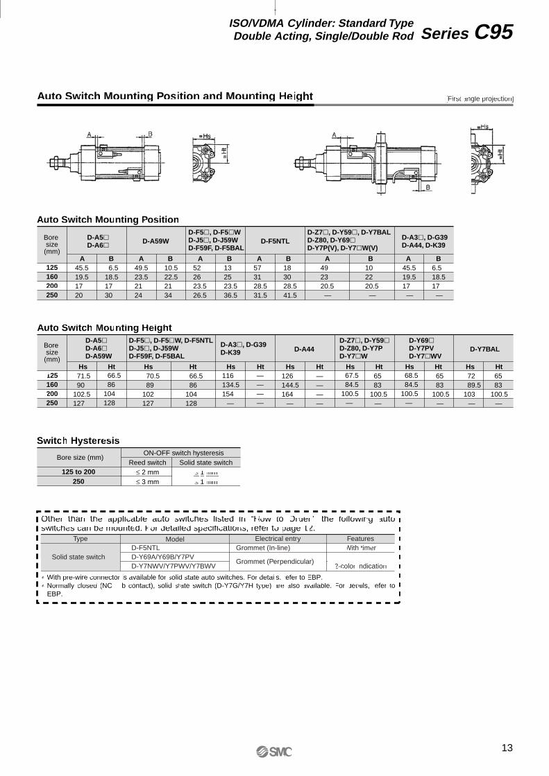
Auto Switch Mounting Position and Mounting Height
Auto Switch Mounting Position
Switch Hysteresis
Auto Switch Mounting Height
Bore size
(mm)
125160200250
D-A5�D-A6�
BA BA BA BA BA BA
D-A59WD-F5�, D-F5�WD-J5�, D-J59WD-F59F, D-F5BAL
D-Z7�, D-Y59�, D-Y7BALD-Z80, D-Y69�D-Y7P(V), D-Y7�W(V)
D-F5NTL D-A3�, D-G39D-A44, D-K39
Bore size
(mm)
125160200250
71.590
102.5127
66.586
104128
D-Y7BAL
67.584.5
100.5—
68.584.5
100.5—
6583
100.5—
6583
100.5—
6583
100.5—
7289.5
103—
126144.5164
—
————
D-Y69�D-Y7PVD-Y7�WV
116134.5154
—
————
70.589
102127
66.586
104128
125 to 200250
Reed switch
≤ 2 mm ≤ 3 mm
ON-OFF switch hysteresisSolid state switch
≤ 1 mm≤ 1 mm
Other than the applicable auto switches listed in “How to Order”, the following auto switches can be mounted. For detailed specifications, refer to page 12.
∗ With pre-wire connector is available for solid state auto switches. For details, refer to EBP. ∗ Normally closed (NC = b contact), solid state switch (D-Y7G/Y7H type) are also available. For details, refer to
EBP.
Solid state switch
Type ModelD-F5NTLD-Y69A/Y69B/Y7PVD-Y7NWV/Y7PWV/Y7BWV
Grommet (In-line)
Grommet (Perpendicular)
Electrical entryWith timer
—2-color indication
Features
45.519.51720
6.518.51730
49.523.52124
10.522.52134
52 26 23.5 26.5
13 25 23.536.5
573128.531.5
183028.541.5
492320.5 —
102220.5 —
45.519.517 —
6.518.517 —
D-A5�D-A6�D-A59W
D-F5�, D-F5�W, D-F5NTLD-J5�, D-J59WD-F59F, D-F5BAL
D-A3�, D-G39D-K39 D-A44
D-Z7�, D-Y59�D-Z80, D-Y7PD-Y7�W
Hs Ht Hs Ht Hs Ht Hs Ht Hs Ht Hs HtHs Ht
Bore size (mm)
[First angle projection]
13
Series C95ISO/VDMA Cylinder: Standard TypeDouble Acting, Single/Double Rod

Series C95Specific Product PrecautionsBe sure to read before handling.
Adjustment
Warning
Bore size (mm) Cushion valve Widthacross flats
Widthacross flats
Socket wrench
125, 160,200, 250
MB-A2-10-EA064 4 JIS 4648Hex spanner wrench 4
Bore size (mm) BoltTightening torque
(Nm)
125
160, 200
M12 x 1.75 x 25l
M16 x 2 x 30l
M20 x 2.5 x 35l
M20 x 2.5 x 30l
10
14
17
17
30.1
99
193.5250Foot
Others
1. Do not open the cushion valve above the stopper.Cushion valves are provided with a retaining ring (ø125 to ø250) as a stopping mechanism, and the cushion valve should not be opened above that point.If air is supplied and operation started without confirming the above condition, the cushion valve may be ejected from the cover.
2. Be certain to activate the air cushion at the stroke end.When it is intended to use the cushion valve in the fully ope-ned position, select a style with a damper. If this is not done, the tie-rods or piston rod assembley will be damaged.
3. When replaceing brackets, use the hexagon wrench shown below.
14


SMC CORPORATION 1-16-4 Shimbashi, Minato-ku, Tokio 105 JAPAN; Phone:03-3502-2740 Fax:03-3508-2480Specifications are subject to change without prior notice
and any obligation on the part of the manufacturer.
ARGENTINA, AUSTRALIA, BOLIVIA, BRASIL, CANADA, CHILE,CHINA, HONG KONG, INDIA, INDONESIA, MALAYSIA, MEXICO,NEW ZEALAND, PHILIPPINES, SINGAPORE, SOUTH KOREA,
TAIWAN, THAILAND, USA, VENEZUELA
OTHER SUBSIDIARIES WORLDWIDE:
© DiskArt™ 1988
© DiskArt™ UKSMC Pneumatics (UK) LtdVincent Avenue, Crownhill, Milton Keynes, MK8 0ANPhone: +44 (0)800 1382930 Fax: +44 (0)1908-555064E-mail: [email protected]://www.smcpneumatics.co.uk
AustriaSMC Pneumatik GmbH (Austria).Girakstrasse 8, A-2100 KorneuburgPhone: +43 2262-62280, Fax: +43 2262-62285E-mail: [email protected]://www.smc.at
Czech RepublicSMC Industrial Automation CZ s.r.o.Hudcova 78a, CZ-61200 BrnoPhone: +420 5 414 24611, Fax: +420 5 412 18034E-mail: [email protected]://www.smc.cz
PortugalSMC Sucursal Portugal, S.A.Rua de Engº Ferreira Dias 452, 4100-246 PortoPhone: +351 22-610-89-22, Fax: +351 22-610-89-36E-mail: [email protected]://www.smces.es
BelgiumSMC Pneumatics N.V./S.A.Nijverheidsstraat 20, B-2160 WommelgemPhone: +32 (0)3-355-1464, Fax: +32 (0)3-355-1466E-mail: [email protected]://www.smcpneumatics.be
LithuaniaUAB Ottensten LietuvaSavanoriu pr. 180, LT-2600 Vilnius, LithuaniaPhone/Fax: +370-2651602
LatviaSMC Pneumatics Latvia SIASmerla 1-705, Riga LV-1006, LatviaPhone: +371 (0)777-94-74, Fax: +371 (0)777-94-75E-mail: [email protected]://www.smclv.lv
SwedenSMC Pneumatics Sweden ABEkhagsvägen 29-31, S-141 71 HuddingePhone: +46 (0)8-603 12 00, Fax: +46 (0)8-603 12 90E-mail: [email protected]://www.smc.nu
FranceSMC Pneumatique, S.A.1, Boulevard de Strasbourg, Parc Gustave EiffelBussy Saint Georges F-77607 Marne La Vallee Cedex 3Phone: +33 (0)1-6476 1000, Fax: +33 (0)1-6476 1010E-mail: [email protected]://www.smc-france.fr
FinlandSMC Pneumatics Finland OYPL72, Tiistinniityntie 4, SF-02031 ESPOOPhone: +358 (0)9-859 580, Fax: +358 (0)9-8595 8595E-mail: [email protected]://www.smc.fi
EstoniaSMC Pneumatics Estonia OÜLaki 12-101, 106 21 TallinnPhone: +372 (0)6 593540, Fax: +372 (0)6 593541E-mail: [email protected]://www.smcpneumatics.ee
GreeceS. Parianopoulus S.A.7, Konstantinoupoleos Street, GR-11855 AthensPhone: +30 (0)1-3426076, Fax: +30 (0)1-3455578E-mail: [email protected]://www.smceu.com
TurkeyEntek Pnömatik San. ve Tic Ltd. Sti.Perpa Tic. Merkezi Kat: 11 No: 1625, TR-80270 Okmeydani IstanbulPhone: +90 (0)212-221-1512, Fax: +90 (0)212-221-1519E-mail: [email protected]://www.entek.com.tr
PolandSMC Industrial Automation Polska Sp.z.o.o.ul. Konstruktorska 11A, PL-02-673 Warszawa, Phone: +48 22 548 5085, Fax: +48 22 548 5087E-mail: [email protected]://www.smc.pl
NetherlandsSMC Pneumatics BVDe Ruyterkade 120, NL-1011 AB AmsterdamPhone: +31 (0)20-5318888, Fax: +31 (0)20-5318880E-mail: [email protected]://www.smcpneumatics.nl
IrelandSMC Pneumatics (Ireland) Ltd.2002 Citywest Business Campus, Naas Road, Saggart, Co. DublinPhone: +353 (0)1-403 9000, Fax: +353 (0)1-464-0500E-mail: [email protected]://www.smcpneumatics.ie
HungarySMC Hungary Ipari Automatizálási Kft.Budafoki ut 107-113, H-1117 BudapestPhone: +36 1 371 1343, Fax: +36 1 371 1344E-mail: [email protected]://www.smc-automation.hu
SwitzerlandSMC Pneumatik AGDorfstrasse 7, CH-8484 WeisslingenPhone: +41 (0)52-396-3131, Fax: +41 (0)52-396-3191E-mail: [email protected]://www.smc.ch
ItalySMC Italia S.p.AVia Garibaldi 62, I-20061Carugate, (Milano)Phone: +39 (0)2-92711, Fax: +39 (0)2-9271365E-mail: [email protected]://www.smcitalia.it
GermanySMC Pneumatik GmbHBoschring 13-15, D-63329 EgelsbachPhone: +49 (0)6103-4020, Fax: +49 (0)6103-402139E-mail: [email protected]://www.smc-pneumatik.de
SloveniaSMC industrijska Avtomatika d.o.o.Grajski trg 15, SLO-8360 ZuzemberkPhone: +386 738 85240 Fax: +386 738 85249E-mail: [email protected]://www.smc-ind-avtom.si
SlovakiaSMC Priemyselná Automatizáciá, s.r.o.Námestie Martina Benku 10, SK-81107 BratislavaPhone: +421 2 444 56725, Fax: +421 2 444 56028E-mail: [email protected]://www.smc.sk
RomaniaSMC Romania srlStr Frunzei 29, Sector 2, BucharestPhone: +40 213205111, Fax: +40 213261489E-mail: [email protected]://www.smcromania.ro
NorwaySMC Pneumatics Norway A/SVollsveien 13 C, Granfos Næringspark N-1366 LysakerTel: +47 67 12 90 20, Fax: +47 67 12 90 21E-mail: [email protected]://www.smc-norge.no
DenmarkSMC Pneumatik A/SKnudsminde 4B, DK-8300 OdderPhone: +45 70252900, Fax: +45 70252901E-mail: [email protected]://www.smcdk.com
RussiaSMC Pneumatik LLC.36/40 Sredny pr. St. Petersburg 199004Phone.:+812 118 5445, Fax:+812 118 5449E-mail: [email protected]://www.smc-pneumatik.ru
SpainSMC España, S.A.Zuazobidea 14, 01015 VitoriaPhone: +34 945-184 100, Fax: +34 945-184 124E-mail: [email protected]://www.smces.es
http://www.smceu.comhttp://www.smcworld.com
EUROPEAN SUBSIDIARIES:
Produced and printed by SMC European Marketing Centre 2/05
BulgariaSMC Industrial Automation Bulgaria EOOD16 kliment Ohridski Blvd., fl.13 BG-1517 SofiaPhone:+359 2 9744492, Fax:+359 2 9744519E-mail: [email protected]://www.smc.bg
CroatiaSMC Industrijska automatika d.o.o.Crnomerec 12, 10000 ZAGREBPhone: +385 1 377 66 74, Fax: +385 1 377 66 74E-mail: [email protected]://www.smceu.com