Embed Size (px)
Citation preview
CJ1
CJP
CJ2
CM2
C85
C76
CG1
MB
MB1
CP95
C95
C92
CA1
CS1
1.6-1
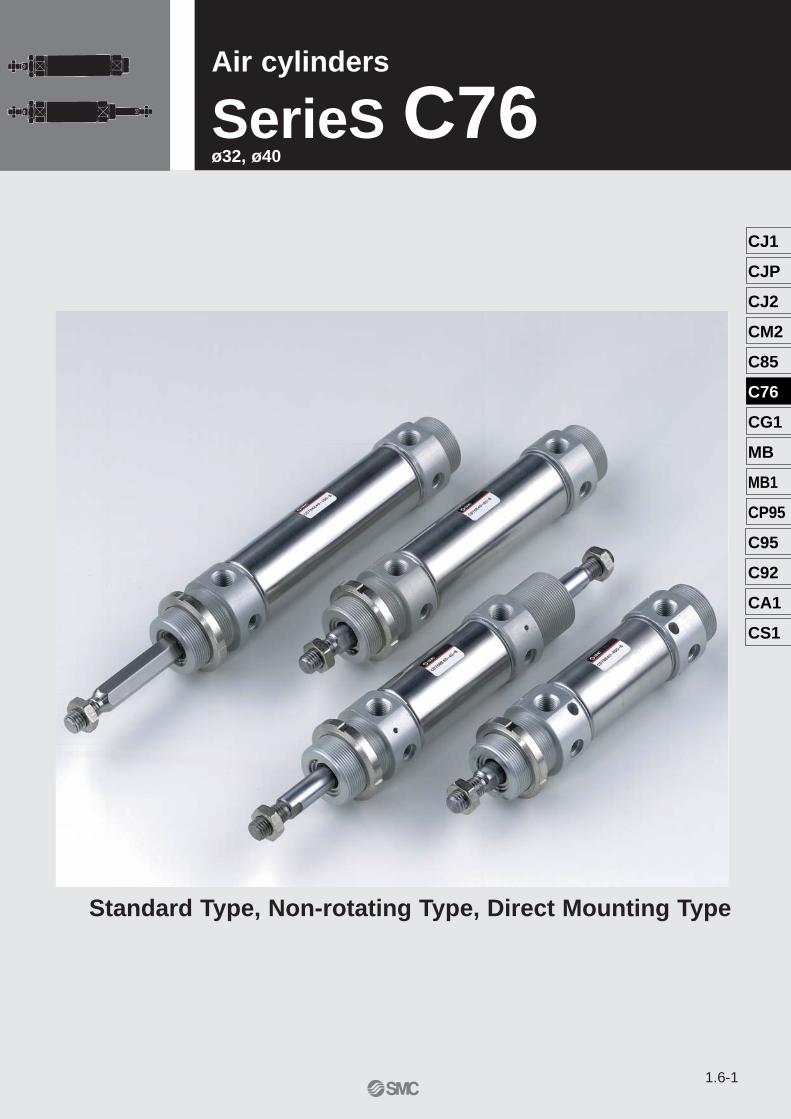
Standard: Double Acting Single Rod Series C76Air cylinders
SerieS C76 ø32, ø40
Standard Type, Non-rotating Type, Direct Mounting Type
1.6-2
Standard
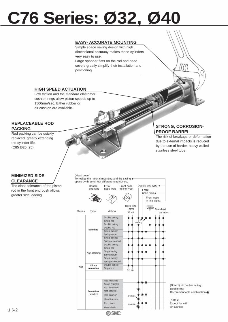
C76 Series: Ø32, Ø40EASY- ACCURATE MOUNTINGSimple space saving design with highdimensional accuracy makes these cylindersvery easy to use.Large spanner flats on the rod and headcovers greatly simplify their installation andpositioning.
HIGH SPEED ACTUATIONLow friction and the standard elastomercushion rings allow piston speeds up to 1500mm/sec. Either rubber or air cushion are available.
Front nosein line type
Double end type
C76
32 40
Front nose type
(Head cover)To realize the rational mounting and the saving space by three or four different head covers.
Front nosein line type
Frontnose type
Doubleend type
Non-rotating
Mountingbracket
32 40
Direct mounting
Bore size(mm)
Double acting:
Single rod
Double acting:
Double rod
Single acting:
Spring return
Single acting:
Spring extended
Double acting:
Single rod
Single acting:
Spring return
Single acting:
Spring extended
Double acting:
Single rod
Rod foot /Rod
flange (Single)
Rod and head
foot (Double)
Rod trunnion
Head trunnion
Rod clevis
Head clevis
Series Type ActionStandard
variation
(Note1)
(Note1)
(Note2)
(Note 1) No double acting: Double rod: Recommendable combination
(Note 2) Except for withair cushion
STRONG, CORROSION-PROOF BARRELThe risk of breakage or deformationdue to external impacts is reducedby the use of harder, heavy walledstainless steel tube.
MINIMIZED SIDE CLEARANCEThe close tolerance of the pistonrod in the front end bush allowsgreater side loading.
REPLACEABLE RODPACKINGRod packing can be quicklyreplaced, greatly extendingthe cylinder life.(C85 Ø20, 25).
Gaiter
CJ1
CJP
CJ2
CM2
C85
C76
CG1
MB
MB1
CP95
C95
C92
CA1
CS1
1.6-3
Page
DirectmountingStandard (Rubber cushion) Non-rotatingStandard
(Air cushion)Double acting Double rod
Double acting Single rod
Double actingDouble rod
Double actingSingle rod
Single actingSpring returnSpringextended
Double actingSingle rod
Double actingSingle rod
Single actingSpring returnSpringextended
Type
Mounting(Headcover)
Built-inmagnet
Mountingbracket
Non-lubricated
Double endtypeFront nosetypeFront nose inline type
Double endtype
Double endtype
Double endtype
Double endtypeFront nosetypeFront nose inline type
Spring return/Double endtypeFront nose typeFront nose inline typeSpring extend-ed/Double endtype Front nosetype
Front nosetype
Band mounted type, Rail mounted type Band mount-ed type
Bottom sidemountingFront nosemounting
Rod footRod and head footRod flangeRod trunnionHead trunnionRod clevisHead clevis
Rod andhead footFlangeTrunnion
Rod footRod andhead footRod flangeRod trunnionHead trunnionRod clevisHead clevis
Rod footRod and headfootRod flangeRod trunnionHead trunnionRod clevisHead clevis
Rod and headfootFlangeTrunnion
Rod footRod and headfootRod flangeRod trunnionHead trunnionRod clevisHead clevis
Accessories
Standard/Mounting nut, Rodend nutOption/Single knuckle joint,Double knuckle joint (withpin)Floating joint
Standard/Rodend nutOption/Singleknuckle joint,Doubleknuckle joint(with pin)Floating joint
Standard/Mounting nut, Rodend nut, Option/Single knuck-le joint, Double knuckle joint (with pin)Floating joint
Standard/Mounting nut, Rodend nut, Option/Singleknuckle joint, Double knucklejoint (with pin)Floating joint
Standard/Mounting nut, Rod endnut,Option/Singleknuckle jointDouble knucklejoint (with pin)Floating joint
Spring return
Spring extended
Bore size(mm)
Spring return
Spring extended
32, 40 32,40 32,40 32,40 32,40
Spring return/Double endtypeFront nose typeFront nose inline typeSpring extend-ed/Double endtypeFront nose type
P.8÷21 P.22÷38 P.8÷21 P.8÷17 P.22÷38 P.39÷44
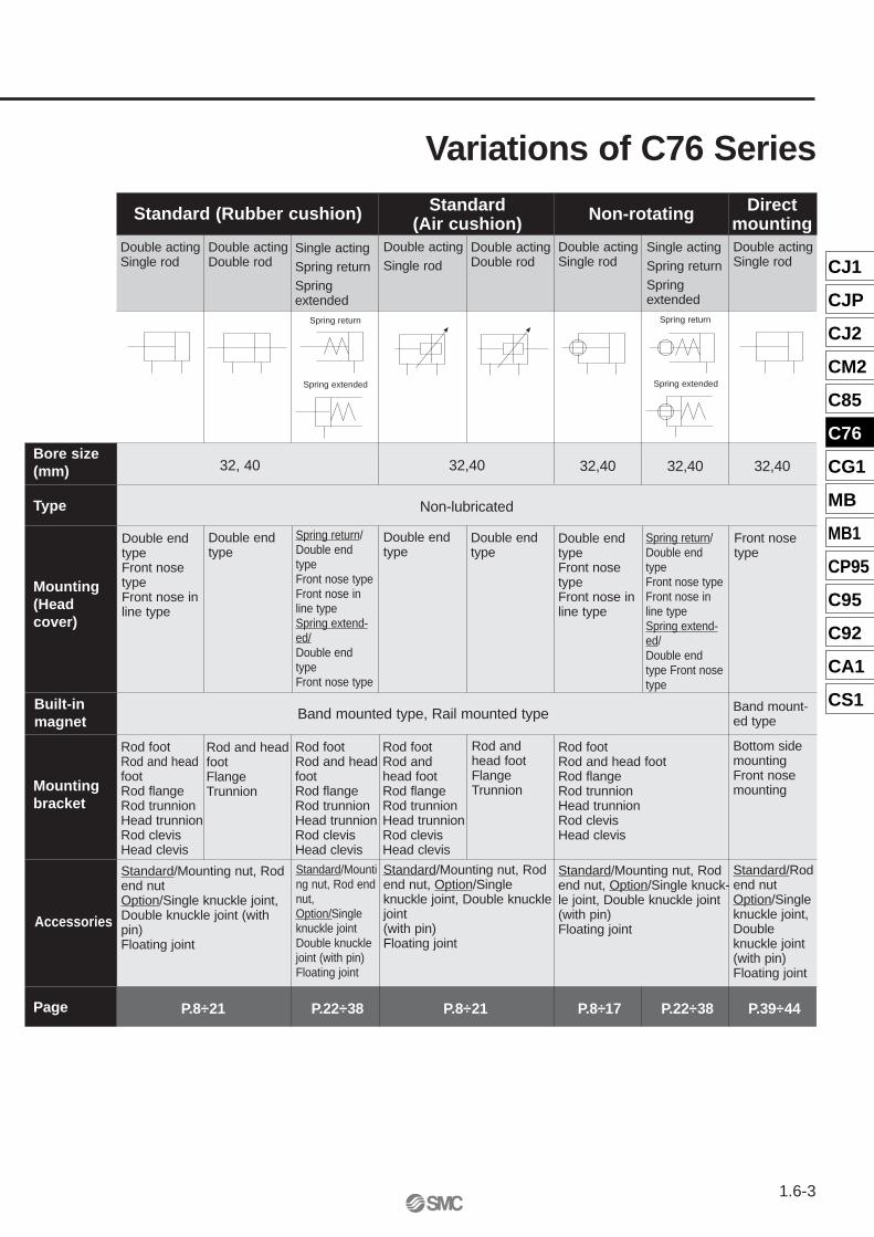
Variations of C76 Series
1.6-4
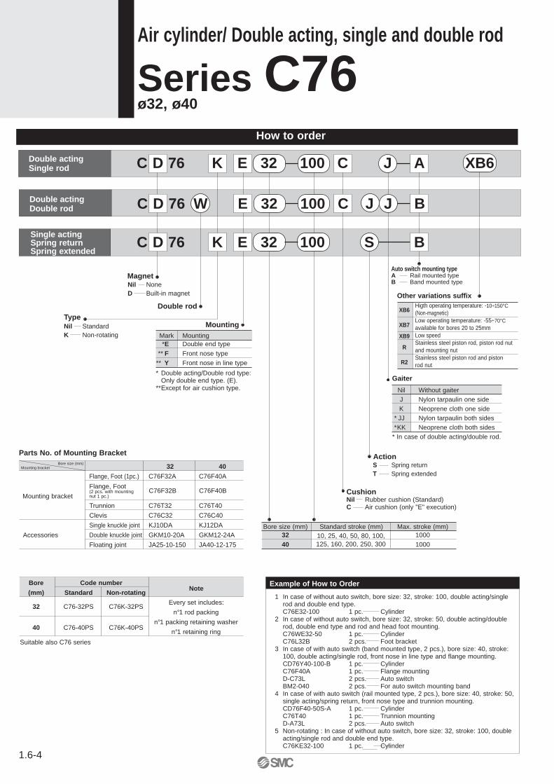
How to order
Air cylinder/ Double acting, single and double rod
Series C76 ø32, ø40
Bore size (mm) Standard stroke (mm) Max. stroke (mm)32 1000
40 1000
Double actingSingle rod
Double actingDouble rod
C D 76 K E 32 100 S BSingle actingSpring returnSpring extended
Magnet
Double rod
MountingTypeNil StandardK Non-rotating Mark Mounting
*E Double end type
** F Front nose type
** Y Front nose in line type
Auto switch mounting typeA Rail mounted typeB Band mounted type
Nil Without gaiterJ Nylon tarpaulin one sideK Neoprene cloth one side
* JJ Nylon tarpaulin both sides*KK Neoprene cloth both sides
* In case of double acting/double rod.
ActionS Spring returnT Spring extended
CushionNil Rubber cushion (Standard)C Air cushion (only "E" execution)
* Double acting/Double rod type:Only double end type. (E).
**Except for air cushion type.Gaiter
10, 25, 40, 50, 80, 100,125, 160, 200, 250, 300
C D 76 W E 32 100 C J J B
Nil NoneD Built-in magnet
Example of How to Order
1 In case of without auto switch, bore size: 32, stroke: 100, double acting/singlerod and double end type.C76E32-100 1 pc. Cylinder
2 In case of without auto switch, bore size: 32, stroke: 50, double acting/doublerod, double end type and rod and head foot mounting.C76WE32-50 1 pc. CylinderC76L32B 2 pcs. Foot bracket
3 In case of with auto switch (band mounted type, 2 pcs.), bore size: 40, stroke:100, double acting/single rod, front nose in line type and flange mounting.CD76Y40-100-B 1 pc. CylinderC76F40A 1 pc. Flange mounting D-C73L 2 pcs. Auto switchBM2-040 2 pcs. For auto switch mounting band
4 In case of with auto switch (rail mounted type, 2 pcs.), bore size: 40, stroke: 50,single acting/spring return, front nose type and trunnion mounting.CD76F40-50S-A 1 pc. CylinderC76T40 1 pc. Trunnion mountingD-A73L 2 pcs. Auto switch
5 Non-rotating : In case of without auto switch, bore size: 32, stroke: 100, doubleacting/single rod and double end type.C76KE32-100 1 pc. Cylinder
Mounting bracketBore size (mm)
Parts No. of Mounting Bracket
Mounting bracketC76F32B C76F40B
Flange, Foot(2 pcs. with mountingnut 1 pc.)
32 40
Flange, Foot (1pc.) C76F32A C76F40A
Trunnion C76T32 C76T40
Clevis C76C32 C76C40
Single knuckle joint KJ10DA KJ12DA
Accessories Double knuckle joint GKM10-20A GKM12-24A
Floating joint JA25-10-150 JA40-12-175
XB6Higth operating temperature: -10÷150°C(Non-magnetic)
XB7Low operating temperature: -55÷70°Cavailable for bores 20 to 25mm
XB9 Low speed
RStainless steel piston rod, piston rod nutand mounting nut
R2Stainless steel piston rod and pistonrod nut
Other variations suffix
C D 76 K E 32 100 C J A XB6
Bore Code number Note
(mm) Standard Non-rotating
Every set includes:32 C76-32PS C76K-32PS
n°1 rod packing
40 C76-40PS C76K-40PSn°1 packing retaining washer
n°1 retaining ring
Suitable also C76 series
CJ1
CJP
CJ2
CM2
C85
C76
CG1
MB
MB1
CP95
C95
C92
CA1
CS1
1.6-5
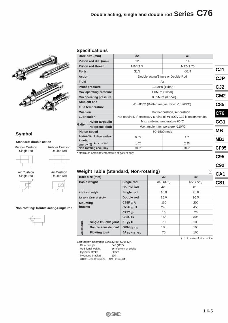
Double acting, single and double rod Series C76
Rubber cushion
Air cushion
Bore size (mm) 32 40
Piston rod dia. (mm) 12 14
Piston rod thread M10x1.5 M12x1.75
Ports G1/8 G1/4
Action Double acting/Single or Double Rod
Fluid Air
Proof pressure 1.5MPa {15bar}
Max operating pressure 1.0MPa {10bar}
Min operating pressure 0.05MPa {0.5bar}
Ambient and-20÷80°C (Built-in magnet type: -10÷60°C)
fluid temperature
Cushion Rubber cushion, Air cushion
Lubrication Not required. If necessary turbine oil #1 ISOVG32 is recommended
Max ambient temperature 60°C
Max ambient temperature *110°C
Piston speed 50÷1500mm/sAllowable 0.65 1.2kineticenergy (J) 1.07 2.35
Non-rotating accuracy ±0.5° ±0.5°
Specifications
Nylon tarpaulin
Neoprene clothGaiter
* Maximum ambient temperature of gaiters only.
Weight Table (Standard, Non-rotating) (g)
Bore size (mm) 32 40
Basic weight Single rod 340 (375) 655 (725)
Double rod 420 810
Additional weight Single rod 16.8 26.6
for each 10mm of stroke Double rod 25.6 96.5
C75F A 110 200
C75F B 240 455
C75T 15 25
C85C 165 305
Single knuckle joint KJ D 70 105
Double knuckle joint GKM - 100 165
Floating joint JA - - 70 160
( ): In case of air cushion
Mountingbracket
Calculation Example: C76E32-50, C76F32ABasic weight 340 (Ø32)Additional weight 16.8/10mm of strokeCylinder stroke 50mmMounting bracket 110340+16.8x50/10=424 424+110=534
Acc
esso
ries
Non-rotating: Double acting/Single rod
Symbol
Rubber CushionSingle rod
Rubber CushionDouble rod
Standard: double action
Air CushionSingle rod
Air CushionDouble rod
1.6-6
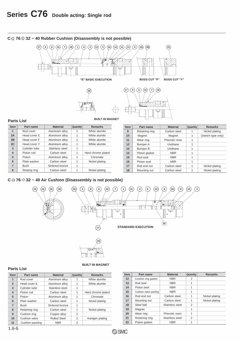
Series C76 Double acting: Single rod
BUILT IN MAGNET
16 4
17
138 6 7 1 11 3 4 14 5 20 9 12 210 1521 18
19
STANDARD EXECUTION22
C 76 32 ~ 40 Air Cushion (Disassembly is not possible)
Item Part name Material Quantity Remarks
12 Cushion ring gasket NBR 2
13 Rod seal NBR 1
14 Piston seal NBR 1
15 Cushion valve packing NBR 1
16 Rod end nut Carbon steel 1 Nickel plating
17 Mounting nut Carbon steel 1 Nickel plating
18 Steel ball Stainless steel 2
19 Magnet 1
20 Wear ring Phenolic resin 1
21 Retaining ring Stainless steel 2
22 Piston gasket NBR 1
Parts ListItem Part name Material Quantity Remarks
1 Rod cover Aluminum alloy 1 White alumite
2 Head cover E Aluminum alloy 1 White alumite
3 Cylinder tube Stainless steel 1
4 Piston rod Carbon steel 1 Hard chrome plated
5 Piston Aluminum alloy 1 Chromate
6 Plain washer Carbon steel 1 Nickel plating
7 Bush Sintered bronze 1
8 Retaining ring Carbon steel 1 Nickel plating
9 Cushion ring Copper alloy 2
10 Cushion valve Rolled Steel 2 Kanigen plating
11 Cushion packing NBR 2
BUILT IN MAGNET
BOSS CUT "F" BOSS CUT "Y"
17 8 6 15 7 18 1 4 3 12 5 16 14 11 13 9 2A 2B 2C
1010 17 8 6 15 7 18
"E" BASIC EXECUTION
Parts ListItem Part name Material Quantity Remarks
1 Rod cover Aluminum alloy 1 White alumite
2A Head cover E Aluminum alloy 1 White alumite
2B Head cover F Aluminum alloy 1 White alumite
2C Head cover Y Aluminum alloy 1 White alumite
3 Cylinder tube Stainless steel 1
4 Piston rod Carbon steel 1 Hard chrome plated
5 Piston Aluminum alloy 1 Chromate
6 Plain washer Carbon steel 1 Nickel plating
7 Bush Sintered bronze 1
8 Retaing ring Carbon steel 1 Nickel plating
Item Part name Material Quantity Remarks
9 Retaining ring Carbon steel 1 Nickel plating
10 Magnet Magnet 1 (Switch type only)
11 Wear ring Phenolic resin 1
12 Bumper A Urethane 1
13 Bumper B Urethane 1
14 Piston gasket NBR 1
15 Rod seal NBR 1
16 Piston seal NBR 1
17 Rod end nut Carbon steel 1 Nickel plating
18 Mounting nut Carbon steel 1 Nickel plating
C 76 32 ~ 40 Rubber Cushion (Disassembly is not possible)
CJ1
CJP
CJ2
CM2
C85
C76
CG1
MB
MB1
CP95
C95
C92
CA1
CS1
1.6-7
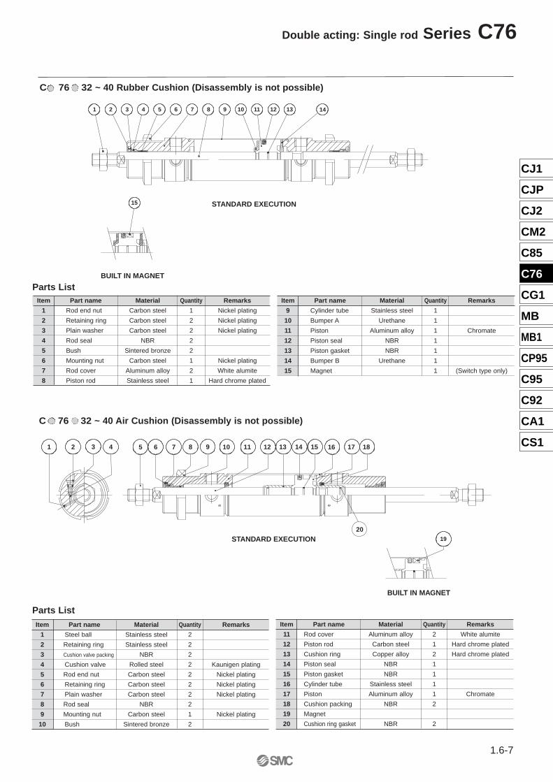
Double acting: Single rod Series C76
1 2 3 4 5 6 7 8 9 10 11 12 13 14
BUILT IN MAGNET
15 STANDARD EXECUTION
Item Part name Material Quantity Remarks
11 Rod cover Aluminum alloy 2 White alumite
12 Piston rod Carbon steel 1 Hard chrome plated
13 Cushion ring Copper alloy 2 Hard chrome plated
14 Piston seal NBR 1
15 Piston gasket NBR 1
16 Cylinder tube Stainless steel 1
17 Piston Aluminum alloy 1 Chromate
18 Cushion packing NBR 2
19 Magnet
20 Cushion ring gasket NBR 2
Item Part name Material Quantity Remarks
1 Steel ball Stainless steel 2
2 Retaining ring Stainless steel 2
3 Cushion valve packing NBR 2
4 Cushion valve Rolled steel 2 Kaunigen plating
5 Rod end nut Carbon steel 2 Nickel plating
6 Retaining ring Carbon steel 2 Nickel plating
7 Plain washer Carbon steel 2 Nickel plating
8 Rod seal NBR 2
9 Mounting nut Carbon steel 1 Nickel plating
10 Bush Sintered bronze 2
Parts List
C 76 32 ~ 40 Air Cushion (Disassembly is not possible)
BUILT IN MAGNET
STANDARD EXECUTION
164 72 3 5 6 8 9 10 11 15121 13 14 17 18
19
20
C 76 32 ~ 40 Rubber Cushion (Disassembly is not possible)
Item Part name Material Quantity Remarks
1 Rod end nut Carbon steel 1 Nickel plating
2 Retaining ring Carbon steel 2 Nickel plating
3 Plain washer Carbon steel 2 Nickel plating
4 Rod seal NBR 2
5 Bush Sintered bronze 2
6 Mounting nut Carbon steel 1 Nickel plating
7 Rod cover Aluminum alloy 2 White alumite
8 Piston rod Stainless steel 1 Hard chrome plated
Parts ListItem Part name Material Quantity Remarks
9 Cylinder tube Stainless steel 1
10 Bumper A Urethane 1
11 Piston Aluminum alloy 1 Chromate
12 Piston seal NBR 1
13 Piston gasket NBR 1
14 Bumper B Urethane 1
15 Magnet 1 (Switch type only)
1.6-8
Series C76 Double acting: Single rod
XB
WH GEE EE
FB
G
2-Ø
Eh
8
XC+Stroke
N
1.50
BE
NFA
1.50KW
H
AM
S+Stroke
KK
ØC
SW K
BE
ZZ+corsa
TW
8
NB
ØKV
HR
45°Rail mounted type (A) Rail type (B)
or non-magnet
4-TC
Cushion valve
XB
WH GEE EE
FB
G
2-Ø
Eh
8
XC+Stroke
N
1.50
BE
NFA
1.50KW
H
AM
S+Stroke
KK
ØC
SW K
BE
ZZ+corsa
TW
8
NB
ØKV
HR
45°
Rail mounted type (A) Band mounted type (B)or non-magnet
4-TC
ØT
DH
9
ØD
KA
8
Wh
h
8
fI
AM
ØC
KK
Øe
K
32 20 12 35 30 10 M10 x 1.540 24 14 46 35 12 M12 x 1.75
I1~50 51~100 101~150 151~200 201~300 301~400 401~500
32 12.5 25 37.5 50 75 100 12540 12.5 25 37.5 50 75 100 125
Wh1~50 51~100 101~150 151~200 201~300 301~400 401~50057 70 82 95 120 145 17064 77 89 102 127 152 177
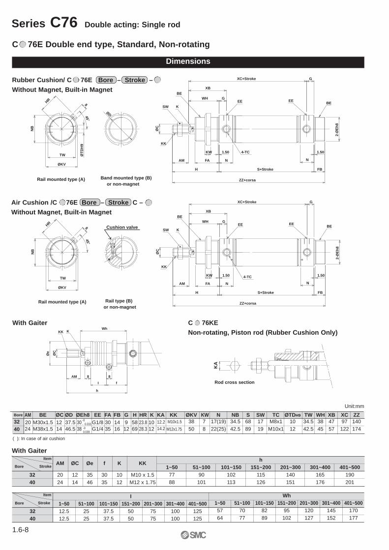
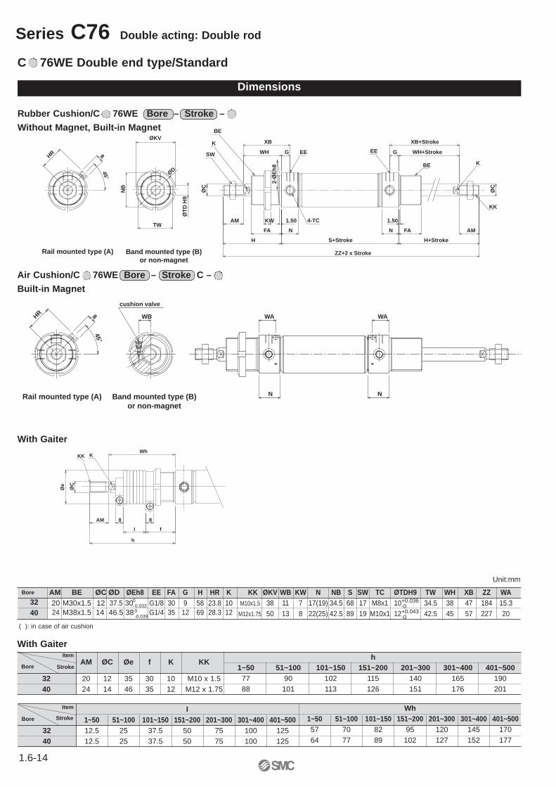
Rubber Cushion/ C 76E Bore – Stroke – Without Magnet, Built-in Magnet
With Gaiter
AM ØC Øe f K KKItem
StrokeBore
Item
StrokeBore
C 76E Double end type, Standard, Non-rotating
Dimensions
h1~50 51~100 101~150 151~200 201~300 301~400 401~500
77 90 102 115 140 165 19088 101 113 126 151 176 201
With Gaiter
Air Cushion /C 76E Bore – Stroke C – Without Magnet, Built-in Magnet
C 76KE Non-rotating, Piston rod (Rubber Cushion Only)
AM BE ØC ØD ØEh8 EE FA FB G H HR K KA20 M30x1.5 12 37.5 30 G1/8 30 14 9 58 23.8 1024 M38x1.5 14 46.5 38 G1/4 35 16 12 69 28.3 12
Bore
3240
KK ØKV KW N NB S SW TC ØTDH9 TW WH XB XC ZZM10x1.5 38 7 17(19) 34.5 68 17 M8x1 10 34.5 38 47 97 140
M12x1.75 50 8 22(25) 42.5 89 19 M10x1 12 42.5 45 57 122 174-00.039
-0- 0.033
Unit:mm
Rod cross section
( ): In case of air cushion
12.214.2
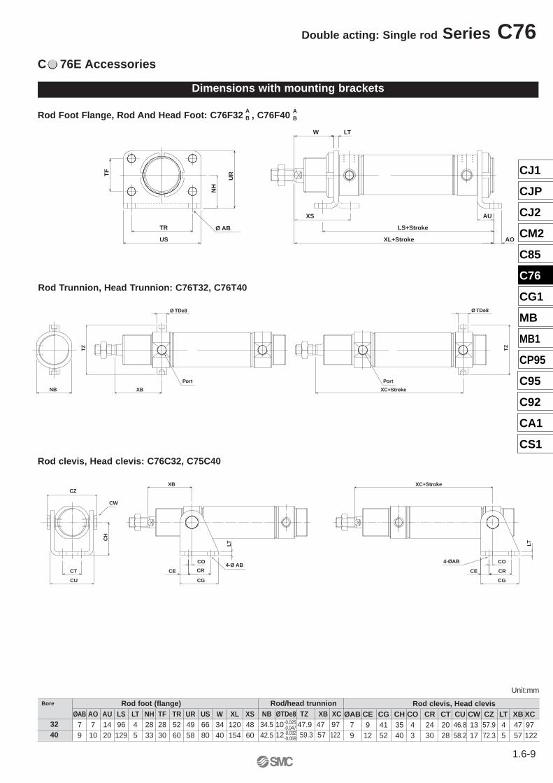
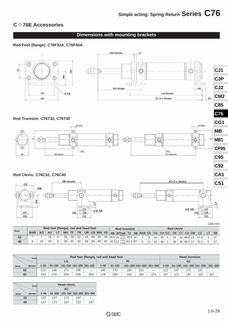
C 76E Accessories
Dimensions with mounting brackets
Rod Foot Flange, Rod And Head Foot: C76F32 , C76F40
AU
XL+Stroke
LS+Stroke
XS
AO
LTW
US
TR Ø AB
TF
NH
UR
TZ
Ø TDe8
XB
Ø TDe8
XC+Stroke
TZ
Port Port
NB
Rod clevis, Head clevis: C76C32, C75C40
4-Ø AB4-ØAB
CW
CO
CRCT
LT LT
CO
CR
XB
CG
CE
XC+Stroke
CU
CE
CG
CH
CZ
Rod Trunnion, Head Trunnion: C76T32, C76T40
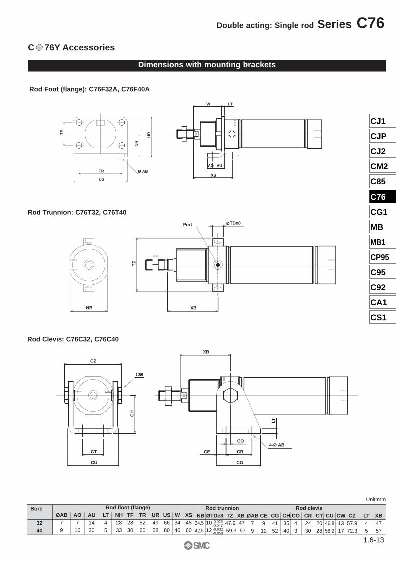
Rod clevis, Head clevisØAB CE CG CH CO CR CT CU CW CZ LT XB XC
7 9 41 35 4 24 20 46.8 13 57.9 4 47 979 12 52 40 3 30 28 58.2 17 72.3 5 57 122
Rod foot (flange)ØAB AO AU LS LT NH TF TR UR US W XL XS
7 7 14 96 4 28 28 52 49 66 34 120 489 10 20 129 5 33 30 60 58 80 40 154 60
Bore
3240 12 59.3 57 122
-0.025-0.047-0.032-0.059
AB
AB
Rod/head trunnionNB ØTDe8 TZ XB XC34.5 10 47.9 47 9742.5
Unit:mm
1.6-9
Double acting: Single rod Series C76
CJ1
CJP
CJ2
CM2
C85
C76
CG1
MB
MB1
CP95
C95
C92
CA1
CS1
1.6-10
Series C76 Double acting: Single rod
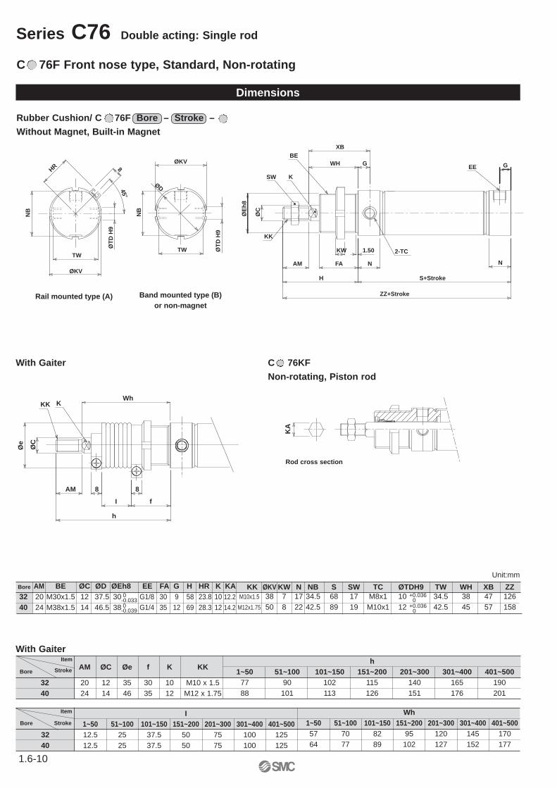
Rubber Cushion/ C 76F Bore – Stroke – Without Magnet, Built-in Magnet
Dimensions
C 76F Front nose type, Standard, Non-rotating
C 76KFNon-rotating, Piston rod
ØT
D H
9
TW
ZZ+Stroke
2-TC
EE
NB
ØKV WH
Band mounted type (B)or non-magnet
G
N
XB
H
AM
S+Stroke
1.50Ø
CKW
NFA
SW
KK
K
BE
ØD
ØE
h8
GHR
NB
8
ØKV
TW
45°
Rail mounted type (A)
ØT
D H
9
KA
8
Wh
h
8
fI
AM
ØC
KK
Øe
K
32 20 12 35 30 10 M10 x 1.540 24 14 46 35 12 M12 x 1.75
I1~50 51~100 101~150 151~200 201~300 301~400 401~500
32 12.5 25 37.5 50 75 100 12540 12.5 25 37.5 50 75 100 125
Wh1~50 51~100 101~150 151~200 201~300 301~400 401~50057 70 82 95 120 145 17064 77 89 102 127 152 177
With Gaiter
AM ØC Øe f K KKItem
StrokeBore
Item
StrokeBore
h1~50 51~100 101~150 151~200 201~300 301~400 401~500
77 90 102 115 140 165 19088 101 113 126 151 176 201
AM BE ØC ØD ØEh8 EE FA G H HR K KA20 M30x1.5 12 37.5 30 G1/8 30 9 58 23.8 10 12.2
24 M38x1.5 14 46.5 38 G1/4 35 12 69 28.3 12 14.2
Bore
3240
+0.0360
+0.0360
KK ØKV KW N NB S SW TC ØTDH9 TW WH XB ZZM10x1.5 38 7 17 34.5 68 17 M8x1 10 34.5 38 47 126
M12x1.75 50 8 22 42.5 89 19 M10x1 12 42.5 45 57 158
Unit:mm
Rod cross section
With Gaiter
0-0.0330
-0.039
1.6-11
Double acting: Single rod Series C76
CJ1
CJP
CJ2
CM2
C85
C76
CG1
MB
MB1
CP95
C95
C92
CA1
CS1
Dimensions with mounting brackets
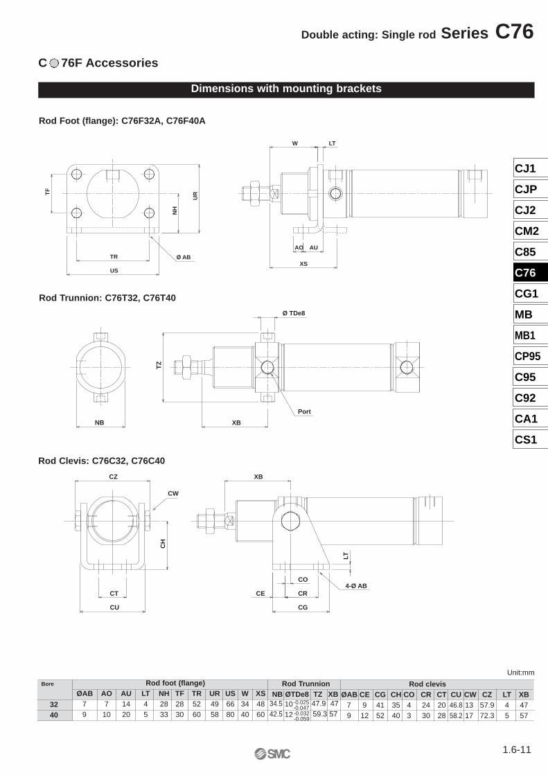
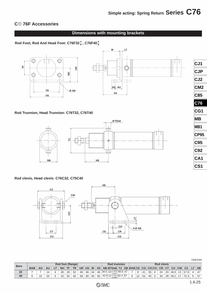
C 76F Accessories
Rod Foot (flange): C76F32A, C76F40A
Rod Trunnion: C76T32, C76T40
Rod Clevis: C76C32, C76C40
TZ
XB
Ø TDe8
Port
NB
AO
XS
AU
LTW
US
TR Ø AB
TF
NH
UR
XB
4-Ø AB
CW
CO
CRCT
LT
CG
CE
CU
CH
CZ
Rod clevisØAB CE CG CH CO CR CT CU CW CZ LT XB
7 9 41 35 4 24 20 46.8 13 57.9 4 479 12 52 40 3 30 28 58.2 17 72.3 5 57
1012
-0.025-0.047-0.032-0.059
Unit:mm
Rod TrunnionNB ØTDe8 TZ XB
34.5 47.9 4742.5 59.3 57
Rod foot (flange)ØAB AO AU LT NH TF TR UR US W XS
7 7 14 4 28 28 52 49 66 34 489 10 20 5 33 30 60 58 80 40 60
Bore
3240
1.6-12
Series C76 Double acting: Single rod
+0.0360
ØKV
EE
2-TC
ZZ+Stroke
ØD
ØT
D H
9
TW
NB
WH G
N
XB
H
AM
S+Stroke
1.50Ø
CKW
NFA
EESW
KK
K
BE
ØE
h8
HR
NB
8
ØKV
45°
Rail mounted type (A)
Band mounted type (B)or non-magnet
I
1~50 51~100 101~150 151~200 201~300 301~400 401~50032 12.5 25 37.5 50 75 100 12540 12.5 25 37.5 50 75 100 125
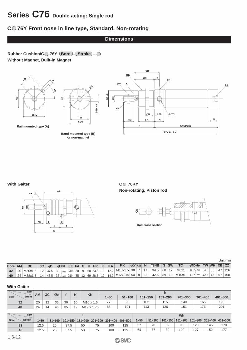
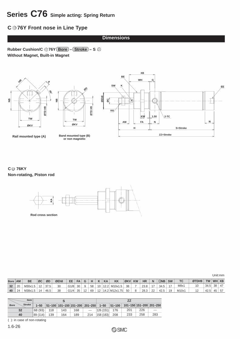
C 76Y Front nose in line type, Standard, Non-rotating
With Gaiter
AM ØC Øe f K KKItem
StrokeBore
Item
StrokeBore
Dimensions
Rubber Cushion/C 76Y Bore – Stroke – Without Magnet, Built-in Magnet
With Gaiter C 76KYNon-rotating, Piston rod
KA
8
Wh
h
8
fI
AM
ØC
KK
Øe
K
Unit:mm
0–0.039
+0.0360
Rod cross section
0–0.033
Bore AM BE φC φD φEh8 EE FA G H HR K KA32 20 M30x1.5 12 37.5 30 G1/8 30 9 58 23.8 10 12.240 24 M38x1.5 14 46.5 38 G1/4 35 12 69 28.3 12 14.2
KK φKV KW N NB S SW TC φTDH9 TW WH XB ZZM10x1.5 38 7 17 34.5 68 17 M8x1 10 34.5 38 47 126M12x1.75 50 8 22 42.5 89 19 M10x1 12 42.5 45 57 158
h1~50 51~100 101~150 151~200 201~300 301~400 401~500
77 90 102 115 140 165 19088 101 113 126 151 176 201
Wh1~50 51~100 101~150 151~200 201~300 301~400 401~50057 70 82 95 120 145 17064 77 89 102 127 152 177
32 20 12 35 30 10 M10 x 1.540 24 14 46 35 12 M12 x 1.75
Dimensions with mounting brackets
C 76Y Accessories
AO
XS
AU
LTW
US
TR Ø AB
TF
NH
UR
TZ
XB
Ø TDe8
NB
Port
4-Ø AB
CW
CO
CRCT
LT
XB
CG
CE
CU
CH
CZ
Rod clevisØAB CE CG CH CO CR CT CU CW CZ LT XB
7 9 41 35 4 24 20 46.8 13 57.9 4 479 12 52 40 3 30 28 58.2 17 72.3 5 57
Rod trunnionNB ØTDe8 TZ XB
34.5 47.9 4742.5 59.3 57
Rod floot (flange)ØAB AO AU LT NH TF TR UR US W XS
7 7 14 4 28 28 52 49 66 34 489 10 20 5 33 30 60 58 80 40 60
Bore
1012
-0.025-0.047-0.032-0.059
3240
Rod Foot (flange): C76F32A, C76F40A
Rod Trunnion: C76T32, C76T40
Rod Clevis: C76C32, C76C40
Unit:mm
1.6-13
Double acting: Single rod Series C76
CJ1
CJP
CJ2
CM2
C85
C76
CG1
MB
MB1
CP95
C95
C92
CA1
CS1
1.6-14
Series C76 Double acting: Double rod
1.50
WH G
XB
NFA
KWAM
H
ØC
SW
K
BE
S+Stroke
2-Ø
Eh
8
EE
4-TC
H+Stroke
N
1.50
FA
ØC
G WH+Stroke
XB+Stroke
KK
AM
BE K
EE
ZZ+2 x Stroke
ØD
ØT
D H
9
TW
NB
ØKV
Rail mounted type (A) Band mounted type (B)or non-magnet
8
45°
HR
32 20 12 35 30 10 M10 x 1.540 24 14 46 35 12 M12 x 1.75
I1~50 51~100 101~150 151~200 201~300 301~400 401~500
32 12.5 25 37.5 50 75 100 12540 12.5 25 37.5 50 75 100 125
Wh1~50 51~100 101~150 151~200 201~300 301~400 401~50057 70 82 95 120 145 17064 77 89 102 127 152 177
Rubber Cushion/C 76WE Bore – Stroke – Without Magnet, Built-in Magnet
With Gaiter
AM ØC Øe f K KKItem
StrokeBore
Item
StrokeBore
C 76WE Double end type/Standard
Dimensions
h1~50 51~100 101~150 151~200 201~300 301~400 401~500
77 90 102 115 140 165 19088 101 113 126 151 176 201
With Gaiter
Air Cushion/C 76WE Bore – Stroke C – Built-in Magnet
8
Wh
h
8
fI
AM
ØC
KK
Øe
K
AM BE ØC ØD ØEh8 EE FA G H HR K20 M30x1.5 12 37.5 30 G1/8 30 9 58 23.8 1024 M38x1.5 14 46.5 38 G1/4 35 12 69 28.3 12
Bore
3240
KK ØKV WB KW N NB S SW TC ØTDH9 TW WH XB ZZ WAM10x1.5 38 11 7 17(19) 34.5 68 17 M8x1 10 34.5 38 47 184 15.3
M12x1.75 50 13 8 22(25) 42.5 89 19 M10x1 12 42.5 45 57 227 20
N N
WA WAWB
cushion valve
Rail mounted type (A)
8
45°
HR
Band mounted type (B)or non-magnet
Unit:mm
0-0.039
0-0.033
+0.036-0+0.043-0
( ): in case of air cushion
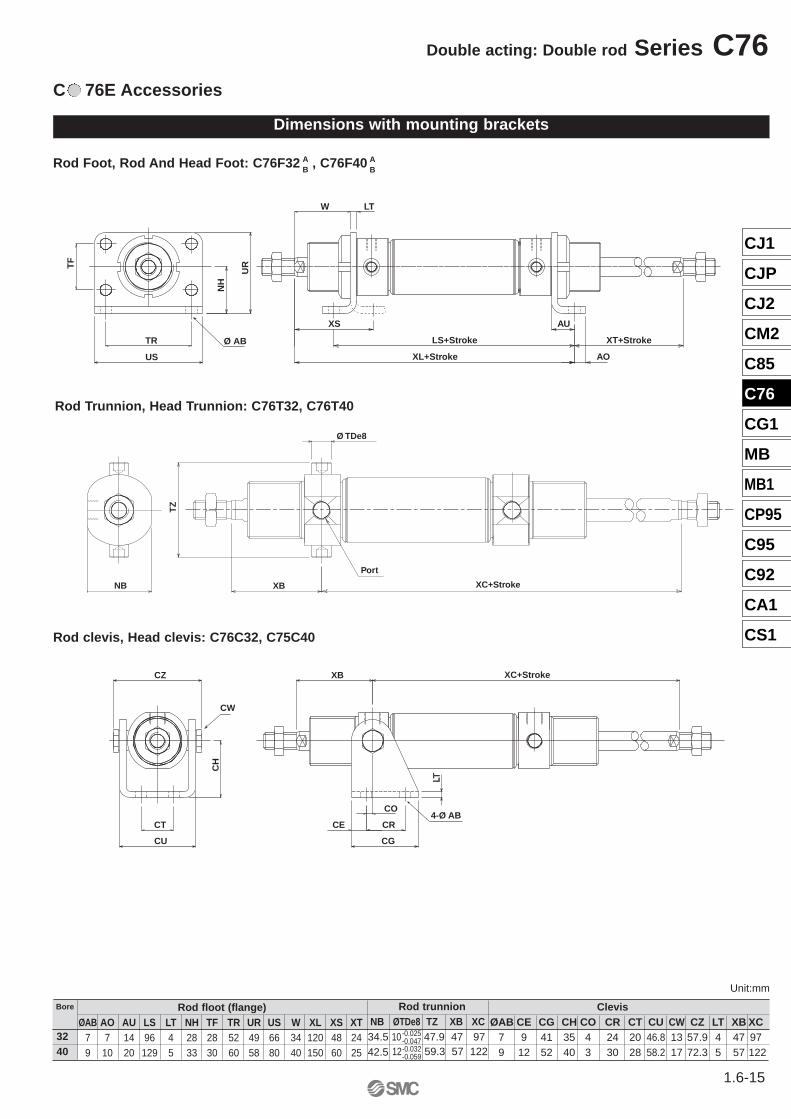
C 76E Accessories
Dimensions with mounting brackets
Rod Foot, Rod And Head Foot: C76F32 , C76F40
Rod clevis, Head clevis: C76C32, C75C40
Rod Trunnion, Head Trunnion: C76T32, C76T40
ClevisØAB CE CG CH CO CR CT CU CW CZ LT XB XC
7 9 41 35 4 24 20 46.8 13 57.9 4 47 979 12 52 40 3 30 28 58.2 17 72.3 5 57 122
Rod floot (flange)ØAB AO AU LS LT NH TF TR UR US W XL XS XT
7 7 14 96 4 28 28 52 49 66 34 120 48 249 10 20 129 5 33 30 60 58 80 40 150 60 25
Bore
3240
Rod trunnionNB ØTDe8 TZ XB XC34.5 10 47.9 47 9742.5
-0.025-0.047
12 59.3 57 122-0.032-0.059
AB
AB
LTW
US
TR Ø AB
UR
NH
TF
LS+Stroke
AO
XS AU
XT+Stroke
XL+Stroke
NB XC+Stroke
TZ
XB
Ø TDe8
Port
CW
4-Ø ABCE
CG
XB
LT
CZ
CU
CR
CO
CH
CT
XC+Stroke
Unit:mm
1.6-15
Double acting: Double rod Series C76
CJ1
CJP
CJ2
CM2
C85
C76
CG1
MB
MB1
CP95
C95
C92
CA1
CS1
1.6-16
Series C76 Double acting: Double rod
Accessories/Dimensions
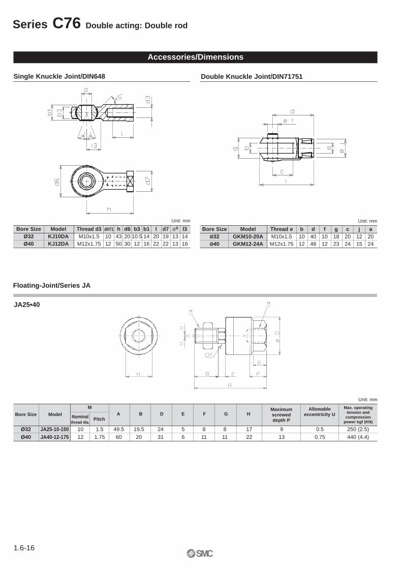
Single Knuckle Joint/DIN648 Double Knuckle Joint/DIN71751
M
Ø32 JA25-10-150 10 1.5 49.5 19.5 24 5 8 8 17 9 0.5 250 (2.5)Ø40 JA40-12-175 12 1.75 60 20 31 6 11 11 22 13 0.75 440 (4.4)
Unit: mm
Nominalthread dia.
Maximum screweddepth P
Allowableeccentricity UA B D E F G HBore Size Model
Pitch
Max. operatingtension and
compressionpower kgf (KN)
Floating-Joint/Series JA
Bore Size Model Thread d3 dH71 h d6 b3 b1 l d7 α0 l3Ø32 KJ10DA M10x1.5 10 43 20 10.5 14 20 19 13 14Ø40 KJ12DA M12x1.75 12 50 30 12 16 22 22 13 16
Unit: mm Unit: mm
Bore Size Model Thread e b d f g c j aØ32 GKM10-20A M10x1.5 10 40 10 18 20 12 20Ø40 GKM12-24A M12x1.75 12 48 12 23 24 15 24
JA25•40
1.6-17
Solid state type type
D-A79WL D-H7CN D-J79CN
A B Hs A B Hs A B Hs A B Hs A B Hs A B Hs A
6 5 31.6 7 6 28.5 7 6 31.5 5.5 4.5 28.5 9 8 30 9 8 34.6 13
11 10 36.1 12 11 32.5 12 11 35.5 10.5 9.5 32.5 14 13 34.5 14 13 39.1 18
Reed type
Bore D-C73L D-C73CN D-A73L D-A73HL D-A73CN
(mm) D-C80L D-C80CN D-A80L D-A80HL D-A80CN
A B Hs A B Hs A B Hs A B Hs A B Hs
32 8 7 28.5 8 7 31 9 8 30.3 9 8 27.8 9 8 36.2
40 13 12 32.5 13 12 35 14 13 34.8 14 13 32.3 14 13 40.7
Double acting Series C76
CJ1
CJP
CJ2
CM2
C85
C76
CG1
MB
MB1
CP95
C95
C92
CA1
CS1
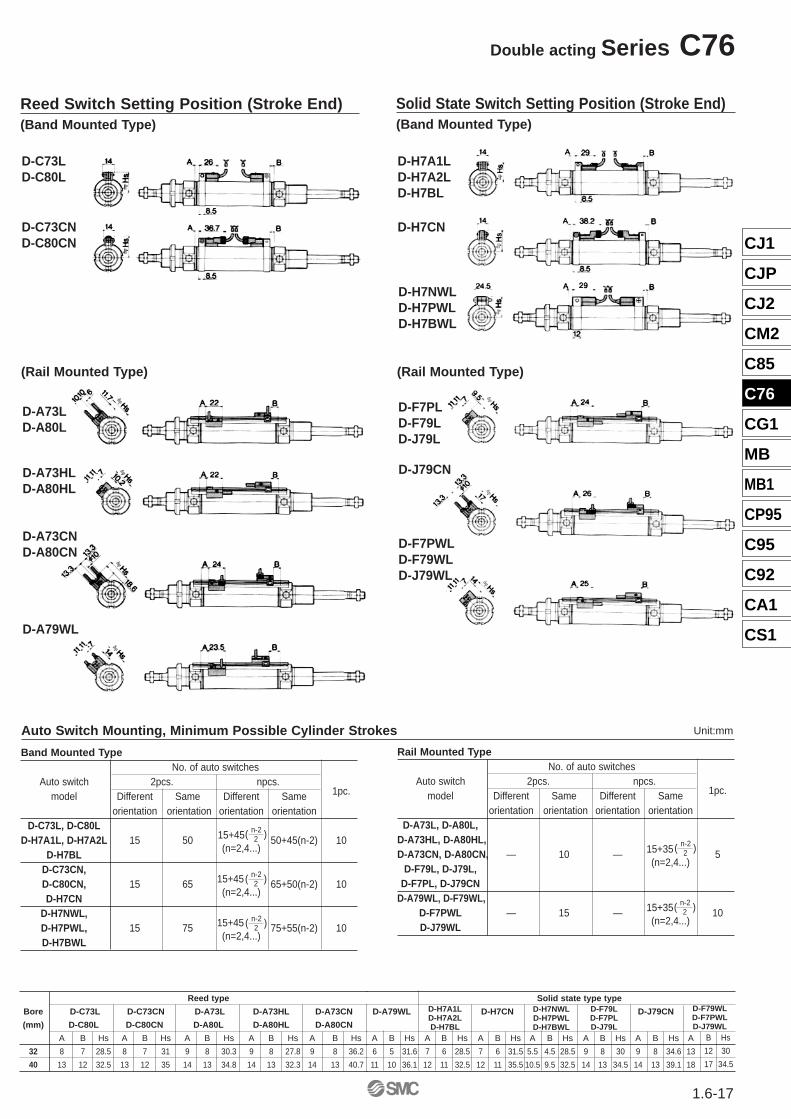
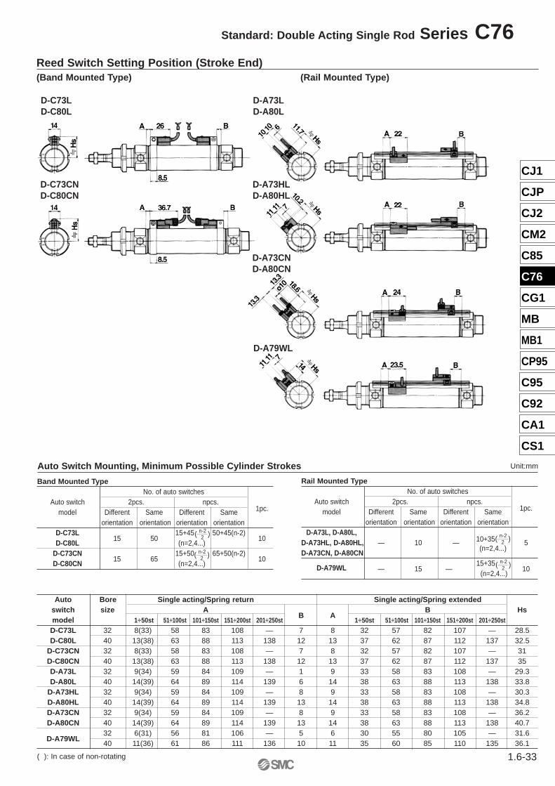
Reed Switch Setting Position (Stroke End)(Band Mounted Type)
Solid State Switch Setting Position (Stroke End)(Band Mounted Type)
D-C73LD-C80L
D-C73CND-C80CN
(Rail Mounted Type)
D-A73LD-A80L
D-A73HLD-A80HL
D-A73CND-A80CN
D-A79WL
D-H7A1LD-H7A2LD-H7BL
D-H7CN
D-H7NWLD-H7PWLD-H7BWL
(Rail Mounted Type)
D-F7PLD-F79LD-J79L
D-J79CN
D-F7PWLD-F79WLD-J79WL
Band Mounted TypeNo. of auto switches
Auto switch 2pcs. npcs. 1pc.model Different Same Different Same
orientation orientation orientation orientationD-C73L, D-C80L
15+45D-H7A1L, D-H7A2L 15 50 50+45(n-2) 10D-H7BL
(n=2,4...)
D-C73CN, 15+45D-C80CN, 15 65 65+50(n-2) 10
D-H7CN(n=2,4...)
D-H7NWL, 15+45D-H7PWL, 15 75 75+55(n-2) 10
D-H7BWL(n=2,4...)
( n-2 )2
( n-2 )2
( n-2 )2
Auto Switch Mounting, Minimum Possible Cylinder Strokes
Rail Mounted TypeNo. of auto switches
Auto switch 2pcs. npcs. 1pc.model Different Same Different Same
orientation orientation orientation orientationD-A73L, D-A80L,
D-A73HL, D-A80HL,15+35D-A73CN, D-A80CN, — 10 — 5
D-F79L, D-J79L,(n=2,4...)
D-F7PL, D-J79CND-A79WL, D-F79WL,
15+35D-F7PWL — 15 — 10D-J79WL
(n=2,4...)( n-2 )2
( n-2 )2
D-H7A1LD-H7A2LD-H7BL
D-H7NWLD-H7PWLD-H7BWL
B Hs
12 30
17 34.5
Unit:mm
D-F79LD-F7PLD-J79L
D-F79WLD-F7PWLD-J79WL
1.6-18
Single acting: spring return/spring extended
Series C76 Bore size: ø32, ø40
Specifications
Bore size (mm) 32 40
Piston rod dia. (mm) 12 14
Piston rod thread M10x1.5 M12x1.75
Ports G1/8 G1/4
Action Single acting/single rod, spring return, spring extended
Fluid Air
Proof pressure 1.5MPa {15bar}
Max operating pressure 1.0MPa {10bar}
Min operating pressure Spring return: 0.18MPa (1.8bar) spring extended: 0.23MPa (2.3bar)
Ambient and-20÷80°C (Built-in magnet type: -10÷60°C)
fluid temperature
Lubrication None (Non lubrificated)
Piston speed 50÷750mm/s
Allowable kinetic
energy (J)0.65 1.2
Non-rotating
accuracy±0.5° ±0.5°
Spring return (N)
Symbol
Bore
size
(mm)
32
40
Standard
stroke
10, 25,
50, 100
150, 200
10, 25
50, 100
150, 200
250
Extendedposition
Retractingposition
Extendedposition
Retractingposition
Extendedposition
Extendedposition
Extendedposition
Extendedposition
Extendedposition
Spring force
Bore
size
(mm)
32
40
Standard
stroke
10, 25,
50, 100
150, 200
10, 25
50, 100
150, 200
250
Extendedposition
Retractingposition
Spring force
Spring extended (N)
Retractingposition
Retractingposition
Retractingposition
Retractingposition
Retractingposition
Extendedposition
Retractingposition
Extendedposition
Retractingposition
Extendedposition
Retractingposition
Extendedposition
Retractingposition
Extendedposition
Retractingposition
Extendedposition
Retractingposition
StandardSpring return Spring extended
Non-rotatingSpring return Spring extended
53.9 48.8 53.9 41.2 53.9 28.4 66.7 19.6 66.7 18.1 66.7 19.6 — —
78.5 72.6 78.5 63.7 78.5 49 76.5 23.5 76.5 23.5 76.5 23.5 76.5 23.5
10 25 50 100 150 200 250
66.7 56.3 66.7 40.7 66.7 14.7 66.7 19.6 66.7 18.1 66.7 19.6 — —
10 25 50 100 150 200 250
76.5 65.9 76.5 50 76.5 23.5 76.5 23.5 76.5 23.5 76.5 23.5 76.5 23.5
Spring force (Standard, Non-rotating)
CJ1
CJP
CJ2
CM2
C85
C76
CG1
MB
MB1
CP95
C95
C92
CA1
CS1
1.6-19
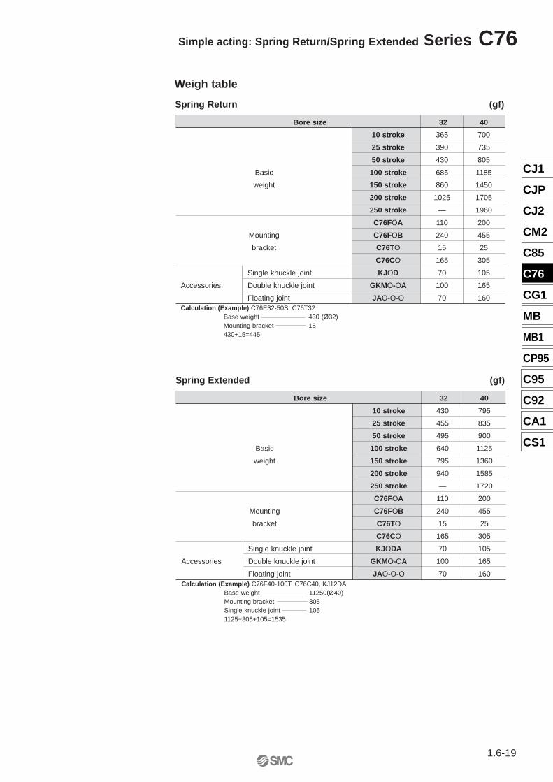
Simple acting: Spring Return/Spring Extended Series C76
Spring Return (gf)
Bore size 32 40
10 stroke 365 700
25 stroke 390 735
50 stroke 430 805
Basic 100 stroke 685 1185
weight 150 stroke 860 1450
200 stroke 1025 1705
250 stroke — 1960
C76FOA 110 200
Mounting C76FOB 240 455
bracket C76TO 15 25
C76CO 165 305
Single knuckle joint KJOD 70 105
Accessories Double knuckle joint GKMO-OA 100 165
Floating joint JAO-O-O 70 160Calculation (Example) C76E32-50S, C76T32
Base weight 430 (Ø32)Mounting bracket 15430+15=445
Weigh table
Spring Extended (gf)
Bore size 32 40
10 stroke 430 795
25 stroke 455 835
50 stroke 495 900
Basic 100 stroke 640 1125
weight 150 stroke 795 1360
200 stroke 940 1585
250 stroke — 1720
C76FOA 110 200
Mounting C76FOB 240 455
bracket C76TO 15 25
C76CO 165 305
Single knuckle joint KJODA 70 105
Accessories Double knuckle joint GKMO-OA 100 165
Floating joint JAO-O-O 70 160Calculation (Example) C76F40-100T, C76C40, KJ12DA
Base weight 11250(Ø40)Mounting bracket 305Single knuckle joint 1051125+305+105=1535
1.6-20
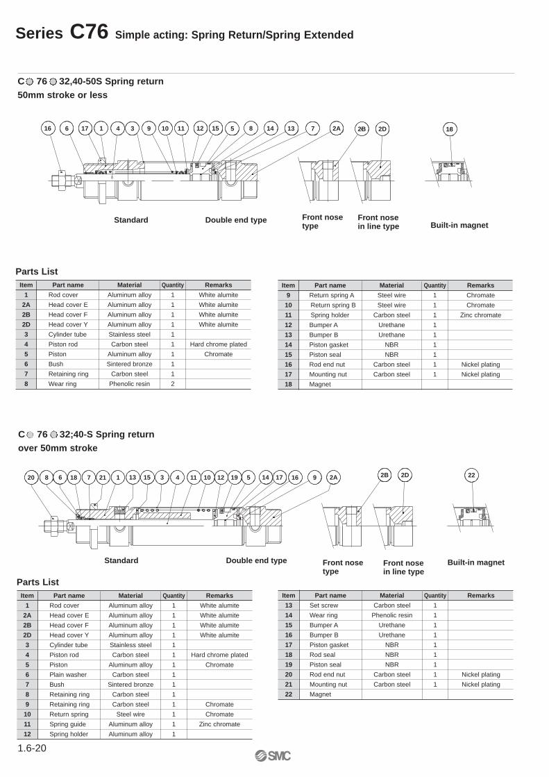
Series C76 Simple acting: Spring Return/Spring Extended
8 6 18 7 21 1 13 15 3 4 11
Standard
10
Double end type
12 19 5 16 9 2A14 1720 2B 2D 22
Front nosetype
Front nosein line type
Built-in magnet
C 76 32;40-S Spring returnover 50mm stroke
Parts ListItem Part name Material Quantity Remarks
1 Rod cover Aluminum alloy 1 White alumite
2A Head cover E Aluminum alloy 1 White alumite
2B Head cover F Aluminum alloy 1 White alumite
2D Head cover Y Aluminum alloy 1 White alumite
3 Cylinder tube Stainless steel 1
4 Piston rod Carbon steel 1 Hard chrome plated
5 Piston Aluminum alloy 1 Chromate
6 Plain washer Carbon steel 1
7 Bush Sintered bronze 1
8 Retaining ring Carbon steel 1
9 Retaining ring Carbon steel 1 Chromate
10 Return spring Steel wire 1 Chromate
11 Spring guide Aluminum alloy 1 Zinc chromate
12 Spring holder Aluminum alloy 1
Item Part name Material Quantity Remarks
13 Set screw Carbon steel 1
14 Wear ring Phenolic resin 1
15 Bumper A Urethane 1
16 Bumper B Urethane 1
17 Piston gasket NBR 1
18 Rod seal NBR 1
19 Piston seal NBR 1
20 Rod end nut Carbon steel 1 Nickel plating
21 Mounting nut Carbon steel 1 Nickel plating
22 Magnet
C 76 32,40-50S Spring return50mm stroke or less
Front nosetype
16 6 17 1
Front nosein line type
3 9 10 11 2B12 15 5 8 14 13 7 2A 182D
Built-in magnetDouble end typeStandard
4
Parts ListItem Part name Material Quantity Remarks
1 Rod cover Aluminum alloy 1 White alumite
2A Head cover E Aluminum alloy 1 White alumite
2B Head cover F Aluminum alloy 1 White alumite
2D Head cover Y Aluminum alloy 1 White alumite
3 Cylinder tube Stainless steel 1
4 Piston rod Carbon steel 1 Hard chrome plated
5 Piston Aluminum alloy 1 Chromate
6 Bush Sintered bronze 1
7 Retaining ring Carbon steel 1
8 Wear ring Phenolic resin 2
Item Part name Material Quantity Remarks
9 Return spring A Steel wire 1 Chromate
10 Return spring B Steel wire 1 Chromate
11 Spring holder Carbon steel 1 Zinc chromate
12 Bumper A Urethane 1
13 Bumper B Urethane 1
14 Piston gasket NBR 1
15 Piston seal NBR 1
16 Rod end nut Carbon steel 1 Nickel plating
17 Mounting nut Carbon steel 1 Nickel plating
18 Magnet
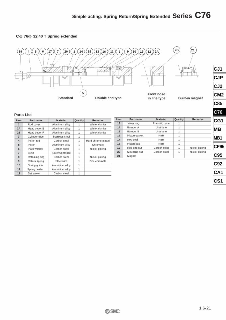
C 76 32,40 T Spring extended
8 6 17 7 20 1 14 18 13 16 911 3 10 15 12 2A 2B
Front nosein line type
19 4
Double end type
21
Built-in magnetStandard5
Parts ListItem Part name Material Quantity Remarks
1 Rod cover Aluminum alloy 1 White alumite
2A Head cover E Aluminum alloy 1 White alumite
2B Head cover F Aluminum alloy 1 White alumite
3 Cylinder tube Stainless steel 1
4 Piston rod Carbon steel 1 Hard chrome plated
5 Piston Aluminum alloy 1 Chromate
6 Plain washer Carbon steel 1 Nickel plating
7 Bush Sintered bronze 1
8 Retaining ring Carbon steel 1 Nickel plating
9 Return spring Steel wire 1 Zinc chromate
10 Spring guide Aluminium alloy 1
11 Spring holder Aluminium alloy 1
12 Set screw Carbon steel 1
Item Part name Material Quantity Remarks
13 Wear ring Phenolic resin 1
14 Bumper A Urethane 1
15 Bumper B Urethane 1
16 Piston gasket NBR 1
17 Rod seal NBR 1
18 Piston seal NBR 1
19 Rod end nut Carbon steel 1 Nickel plating
20 Mounting nut Carbon steel 1 Nickel plating
21 Magnet
CJ1
CJP
CJ2
CM2
C85
C76
CG1
MB
MB1
CP95
C95
C92
CA1
CS1
1.6-21
Simple acting: Spring Return/Spring Extended Series C76
1.6-22
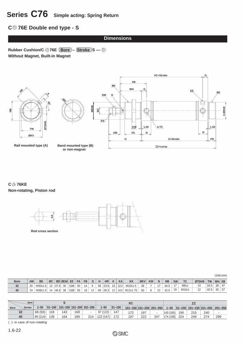
Series C76 Simple acting: Spring Return
Rubber Cushion/C 76E Bore – Stroke S —Without Magnet, Built-in Magnet
C 76E Double end type - S
Dimensions
Item
StrokeBore
S1~50 51~100 101~150 151~200 201~250 1~50 51~100
32 68 (93) 118 143 168 - 97 (122) 14740 89 (114) 139 164 189 214 122 (147) 172
ZZ101~150 151~200 201~250 1~50 51~100 101~150 151~200 201~250
172 197 - 140 (165) 190 215 240 -197 222 247 174 (199) 224 249 274 299
KA
Rod cross section
XB
WH GEE
FB
G
2-Ø
Eh
8
XC+Stroke
N
1.50
BE
NFA
1.50KW
H
AM
S+Stroke
KK
ØC
SW K
BE
ZZ+corsa
TW
8
NB
ØKV
HR
45°
Rail mounted type (A) Band mounted type (B)or non-magnet
4-TC
ØT
DH
9
ØD
ØE
h8
Bore AM BE ØC ØD ØEh8 EE FA FB G H HR K KA KK ØKV KW N NB 32 20 M30x1.5 12 37.5 30 G1/8 30 14 9 58 23.8 10 12.2 M10x1.5 38 7 17 34.5
40 24 M38x1.5 14 46.5 38 G1/8 35 16 12 69 28.3 12 14.2 M12x1.75 50 8 22 42.5
SW TC ØTDH9 TW WH XB17 M8x1 10 34.5 38 4719 M10x1 12 42.5 45 57
XC
Unit:mm
C 76KE Non-rotating, Piston rod
( ): in case of non-rotating
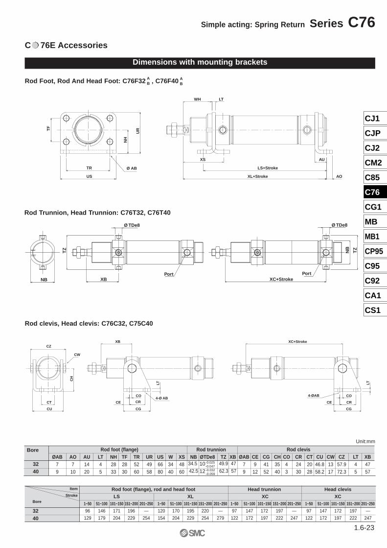
C 76E Accessories
Dimensions with mounting brackets
Rod Foot, Rod And Head Foot: C76F32 , C76F40
Rod clevis, Head clevis: C76C32, C75C40
Rod Trunnion, Head Trunnion: C76T32, C76T40
AB
AB
AU
XL+Stroke
LS+Stroke
XS
AO
LTWH
US
TR Ø AB
TF
NH
UR
Rod clevisØAB CE CG CH CO CR CT CU CW CZ LT XB
7 9 41 35 4 24 20 46.8 13 57.9 4 479 12 52 40 3 30 28 58.2 17 72.3 5 57
Rod trunnionNB ØTDe8 TZ XB
34.5 49.9 4742.5 62.3 57
Rod foot (flange)ØAB AO AU LT NH TF TR UR US W XS
7 7 14 4 28 28 52 49 66 34 489 10 20 5 33 30 60 58 80 40 60
Bore
3240
4-Ø AB4-ØAB
CW
CO
CRCT
LT LT
CO
CR
XB
CG
CE
XC+Stroke
CU
CE
CG
CH
CZ
TZ
NB
Ø TDe8
XB
Ø TDe8
XC+Stroke
TZ
NBPort Port
1012
-0.025-0.047-0.032-0.059
Item
Stroke
Bore
Rod foot (flange), rod and head foot Head trunnion Head clevisLS XL XC XC
1~50 51~100 101~150 151~200 201~250 1~50 51~100 101~150 151~200 201~250 1~50 51~100 101~150 151~200 201~250 1~50 51~100 101~150 151~200 201~250
96 146 171 196 — 120 170 195 220 — 97 147 172 197 — 97 147 172 197 —
129 179 204 229 254 154 204 229 254 279 122 172 197 222 247 122 172 197 222 2473240
Unit:mm
1.6-23
Simple acting: Spring Return Series C76
CJ1
CJP
CJ2
CM2
C85
C76
CG1
MB
MB1
CP95
C95
C92
CA1
CS1
1.6-24
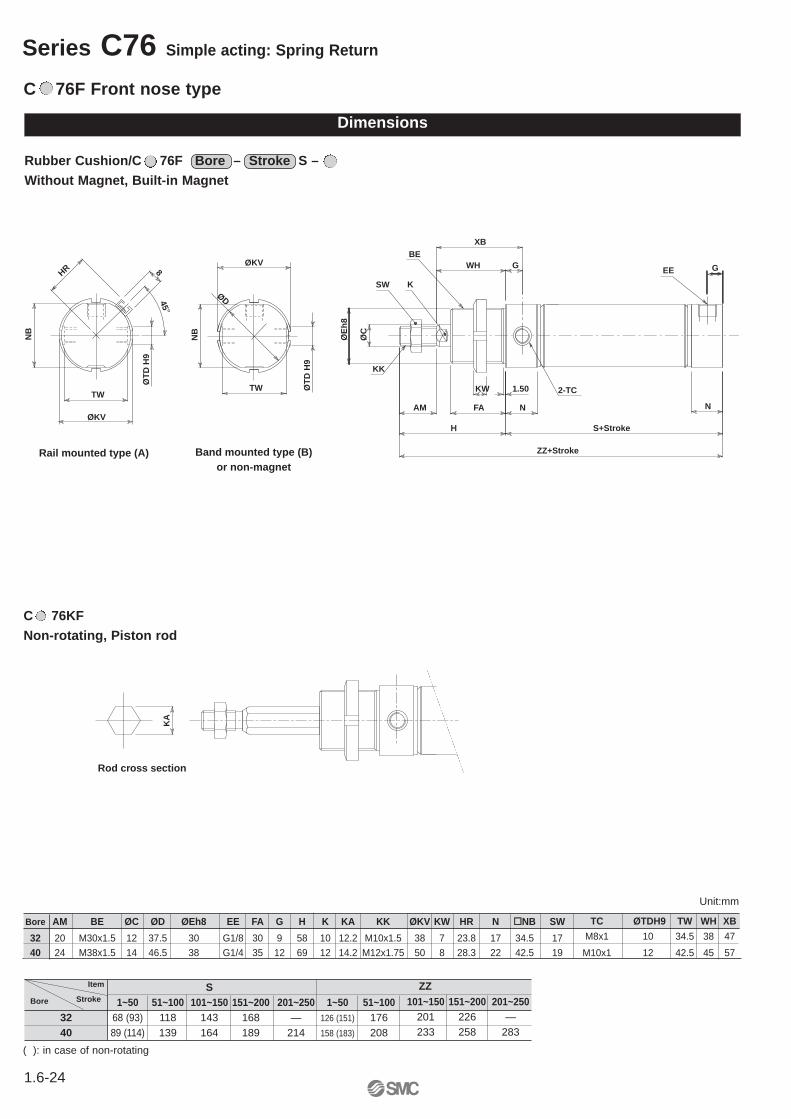
Series C76 Simple acting: Spring Return
Rubber Cushion/C 76F Bore – Stroke S – Without Magnet, Built-in Magnet
Dimensions
101~150 151~200 201~250201 226 —233 258 283
Item
StrokeBore
ZZS1~50 51~100 101~150 151~200 201~250 1~50 51~100
32 68 (93) 118 143 168 — 126 (151) 17640 89 (114) 139 164 189 214 158 (183) 208
Bore AM BE ØC ØD ØEh8 EE FA G H K KA KK ØKV KW HR N NB SW
32 20 M30x1.5 12 37.5 30 G1/8 30 9 58 10 12.2 M10x1.5 38 7 23.8 17 34.5 17
40 24 M38x1.5 14 46.5 38 G1/4 35 12 69 12 14.2 M12x1.75 50 8 28.3 22 42.5 19
ØT
D H
9
TW
ZZ+Stroke
2-TC
EE
NB
ØKV WH
Band mounted type (B)or non-magnet
G
N
XB
H
AM
S+Stroke
1.50
ØC
KW
NFA
SW
KK
K
BE
ØD
ØE
h8
GHR
NB
8
ØKV
TW
45°
Rail mounted type (A)
ØT
D H
9
C 76F Front nose type
TC ØTDH9 TW WH XB
M8x1 10 34.5 38 47
M10x1 12 42.5 45 57
Unit:mm
KA
Rod cross section
C 76KF Non-rotating, Piston rod
( ): in case of non-rotating
C 76F Accessories
Dimensions with mounting brackets
Rod Foot, Rod And Head Foot: C76F32 , C76F40
Rod clevis, Head clevis: C76C32, C75C40
AB
AB
Rod Trunnion, Head Trunnion: C76T32, C76T40
Rod clevisØAB CE CG CH CO CR CT CU CW CZ LT XB
7 9 41 35 4 24 20 46.8 13 57.9 4 479 12 52 40 3 30 28 58.2 17 72.3 5 57
Rod trunnionNB ØTDe8 TZ XB
34.5 49.9 4742.5 62.3 57
Rod foot (flange)ØAB AO AU LT NH TF TR UR US W XS
7 7 14 4 28 28 52 49 66 34 489 10 20 5 33 30 60 58 80 40 60
Bore
1012
-0.025-0.047-0.032-0.059
3240
AO
XS
AU
LTW
US
TR Ø AB
TF
NH
UR
TZ
XB
Ø TDe8
NB
4-Ø AB
CW
CO
CRCT
XB
CG
CE
CU
CH
CZ
LT
Unit:mm
1.6-25
Simple acting: Spring Return Series C76
CJ1
CJP
CJ2
CM2
C85
C76
CG1
MB
MB1
CP95
C95
C92
CA1
CS1
1.6-26
Series C76 Simple acting: Spring Return
Rubber Cushion/C 76Y Bore – Stroke – S Without Magnet, Built-in Magnet
Dimensions
ØKV
EE
2-TC
ZZ+Stroke
ØDØ
TD
H9
TW
NB
WH G
N
XB
H
AM
S+Stroke
1.50
ØC
KW
NFA
SW
KK
K
BE
ØE
h8
Band mounted type (B)or non magnetic
HR
NB
8
ØKV
TW
45°
Rail mounted type (A)
ØT
D H
9
C 76Y Front nose in Line Type
101~150 151~200 201~250201 226 —233 258 283
Item
StrokeBore
ZZS1~50 51~100 101~150 151~200 201~250 1~50 51~100
32 68 (93) 118 143 168 — 126 (151) 17640 89 (114) 139 164 189 214 158 (183) 208
Bore AM BE ØC ØD ØEh8 EE FA G H K KA KK ØKV KW HR N NB SW
32 20 M30x1.5 12 37.5 30 G1/8 30 9 58 10 12.2 M10x1.5 38 7 23.8 17 34.5 17
40 24 M38x1.5 14 46.5 38 G1/4 35 12 69 12 14.2 M12x1.75 50 8 28.3 22 42.5 19
TC ØTDH9 TW WH XB
M8x1 10 34.5 38 47
M10x1 12 42.5 45 57
Unit:mm
KA
Rod cross section
C 76KYNon-rotating, Piston rod
( ): in case of non-rotating
Dimensions with mounting brackets
C 76Y Accessories
Rod Foot (flange): C76F32A, C76F40A
Rod Trunnion: C76T32, C76T40
Rod clevisØAB CE CG CH CO CR CT CU CW CZ LT XB
7 9 41 35 4 24 20 46.8 13 57.9 4 479 12 52 40 3 30 28 58.2 17 72.3 5 57
Rod trunnionNB ØTDes TZ XB
34.5 49.9 4762.3 62.3 57
Rod foot (flange)ØAB AO AU LT NH TF TR UR US W XS
7 7 14 4 28 28 52 49 66 34 489 10 20 5 33 30 60 58 80 40 60
Bore
1012
-0.025-0.047-0.032-0.059
3240
Rod Clevis: C76C32, C76C40
TZ
XB
Ø TDe8
NB
AO
XS
AU
LTW
US
TR Ø AB
TF
NH
UR
4-Ø AB
CW
CO
CRCT
LT
XB
CG
CE
CU
CH
CZ
Unit:mm
1.6-27
Simple acting: Spring Return Series C76
CJ1
CJP
CJ2
CM2
C85
C76
CG1
MB
MB1
CP95
C95
C92
CA1
CS1
1.6-28
Series C76 Simple acting: Spring Return
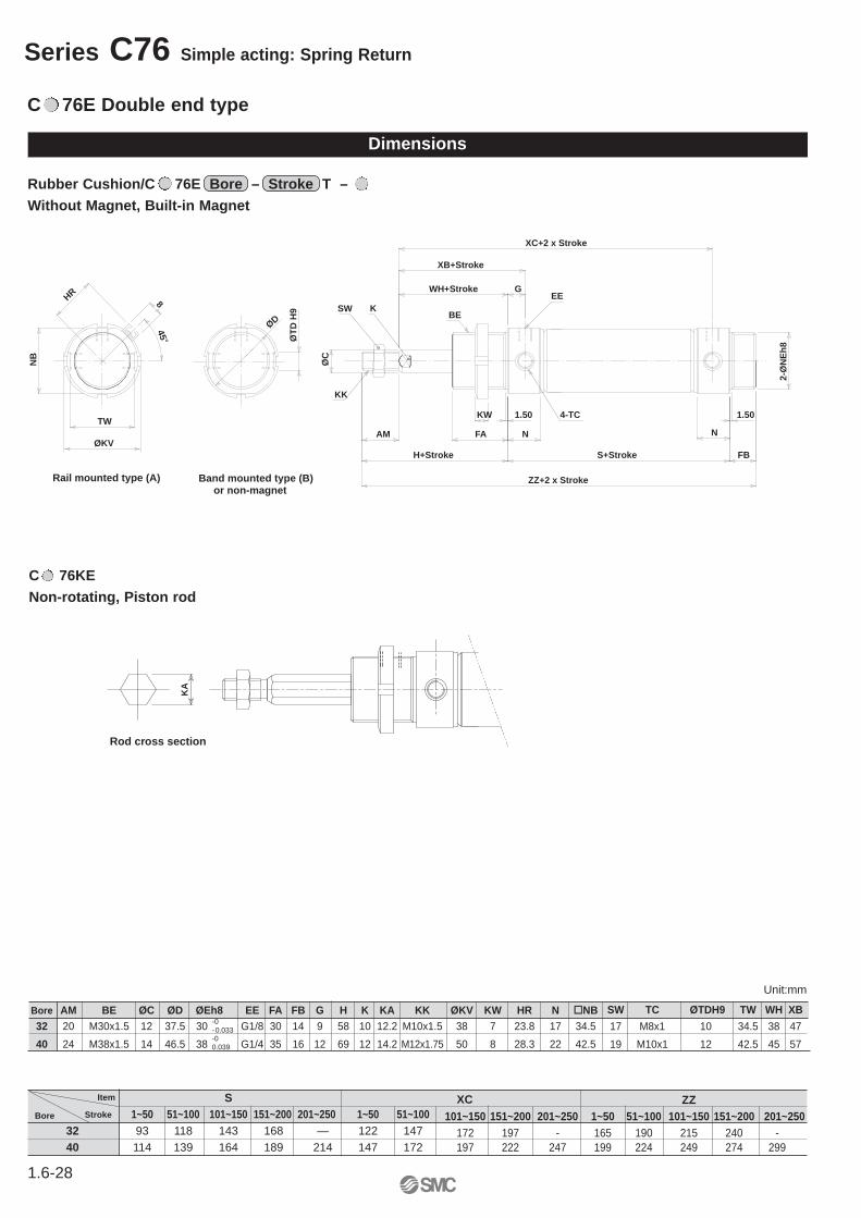
Rubber Cushion/C 76E Bore – Stroke T – Without Magnet, Built-in Magnet
Dimensions
C 76E Double end type
XB+Stroke
WH+Stroke GEE
FB
2-Ø
NE
h8
XC+2 x Stroke
N
1.50
NFA
1.50KW
H+Stroke
AM
S+Stroke
KK
ØC
SW K
ZZ+2 x Stroke
TW
8
NB
ØKV
HR
45°
Rail mounted type (A) Band mounted type (B)or non-magnet
4-TC
ØT
D H
9 BEØD
Bore AM BE ØC ØD ØEh8 EE FA FB G H K KA KK ØKV KW HR N NB32 20 M30x1.5 12 37.5 30 G1/8 30 14 9 58 10 12.2 M10x1.5 38 7 23.8 17 34.5
40 24 M38x1.5 14 46.5 38 G1/4 35 16 12 69 12 14.2 M12x1.75 50 8 28.3 22 42.5-00.039
-0-0.033
SW TC ØTDH9 TW WH XB
17 M8x1 10 34.5 38 47
19 M10x1 12 42.5 45 57
Item
StrokeBore
S1~50 51~100 101~150 151~200 201~250 1~50 51~100
32 93 118 143 168 — 122 14740 114 139 164 189 214 147 172
ZZ101~150 151~200 201~250 1~50 51~100 101~150 151~200 201~250
172 197 - 165 190 215 240 -197 222 247 199 224 249 274 299
XC
Unit:mm
KA
Rod cross section
C 76KE Non-rotating, Piston rod
TZ
Ø TDe8
XB+Stroke
Ø TDe8
XC+2XStroke
TZ
Port Port
NB
Dimensions with mounting brackets
C 76E Accessories
Rod Foot (flange): C76F32A, C76F40A
Rod Trunnion: C76T32, C76T40
Rod clevisØAB CE CG CH CO CR CT CU CW CZ LT XB
7 9 41 35 4 24 20 46.8 13 57.9 4 479 12 52 40 3 30 28 58.2 17 72.3 5 57
Rod trunnionNB ØTDe8 TZ XB
34.5 49.9 4742.5 62.3 57
Rod foot (flange), rod and head footØAB AO AU LT NH TF TR UR US WH XS
7 7 14 4 28 28 52 49 66 34 489 10 20 5 33 30 60 58 80 40 60
Bore
1012
-0.025-0.047-0.032-0.059
3240
Rod Clevis: C76C32, C76C40
AU
XL+2 x Stroke
LS+Stroke
XS+Stroke
AO
LTWH+Stroke
US
TR Ø AB
TF
NH
UR
4-Ø AB4-Ø AB
CW
COCRCT
LT LT
COCR
XB+Stroke
CGCE
XC+2 x Stroke
CUCE
CG
CH
CZ
Item
StrokeBore
Rod foot (flange), rod and head foot Head trunnionLS
1~50 51~100 101~150 151~200 201~250 1~50 51~10032 121 146 171 196 — 145 17040 154 179 204 229 254 179 204
XC101~150 151~200 201~250 1~50 51~100 101~150 151~200 201~250
195 220 — 122 147 172 197 —229 254 279 147 172 197 222 247
XL
Item
StrokeBore
Head clevisXC
1~50 51~100 101~150 151~200 201~25032 122 147 172 197 —40 147 172 197 222 247
Unit:mm
1.6-29
Simple acting: Spring Return Series C76
CJ1
CJP
CJ2
CM2
C85
C76
CG1
MB
MB1
CP95
C95
C92
CA1
CS1
1.6-30
Series C76 Simple acting: Spring extended
C 76F Front nose type
Dimensions
Rubber Cushion/C 76F Bore – Stroke T – Without Magnet, Built-in Magnet
101~150 151~200 201~250201 226 —233 258 283
Item
StrokeBore
ZZS1~50 51~100 101~150 151~200 201~250 1~50 51~100
32 93 118 143 168 — 151 17640 114 139 164 189 214 183 208
Bore AM BE ØC ØD ØEh8 EE FA G H K KA KK ØKV KW HR N NB SW
32 20 M30x1.5 12 37.5 30 G1/8 30 9 58 10 12.2 M10x1.5 38 7 23.8 17 34.5 17
40 24 M38x1.5 14 46.5 38 G1/4 35 12 69 12 14.2 M12x1.75 50 8 28.3 22 42.5 19
TC ØTDH9 TW WH XB
M8x1 10 34.5 38 47
M10x1 12 42.5 45 57
Unit:mm
ØT
D H
9ØD
TW
ZZ+2 x Stroke
2-TC
EE
NB
ØKV
NB
8
ØKV
TW
45°
WH+Stroke
Rail mounted type (A) Band mounted type (B)or non-magnet
G
N
XB+Stroke
H+Stroke
AM
S+Stroke
1.50
ØC
KW
NFA
SW
KK
K BEHR
ØE
h8
KA
Rod cross section
C 76KF Non-rotating, Piston rod
Dimensions with mounting brackets
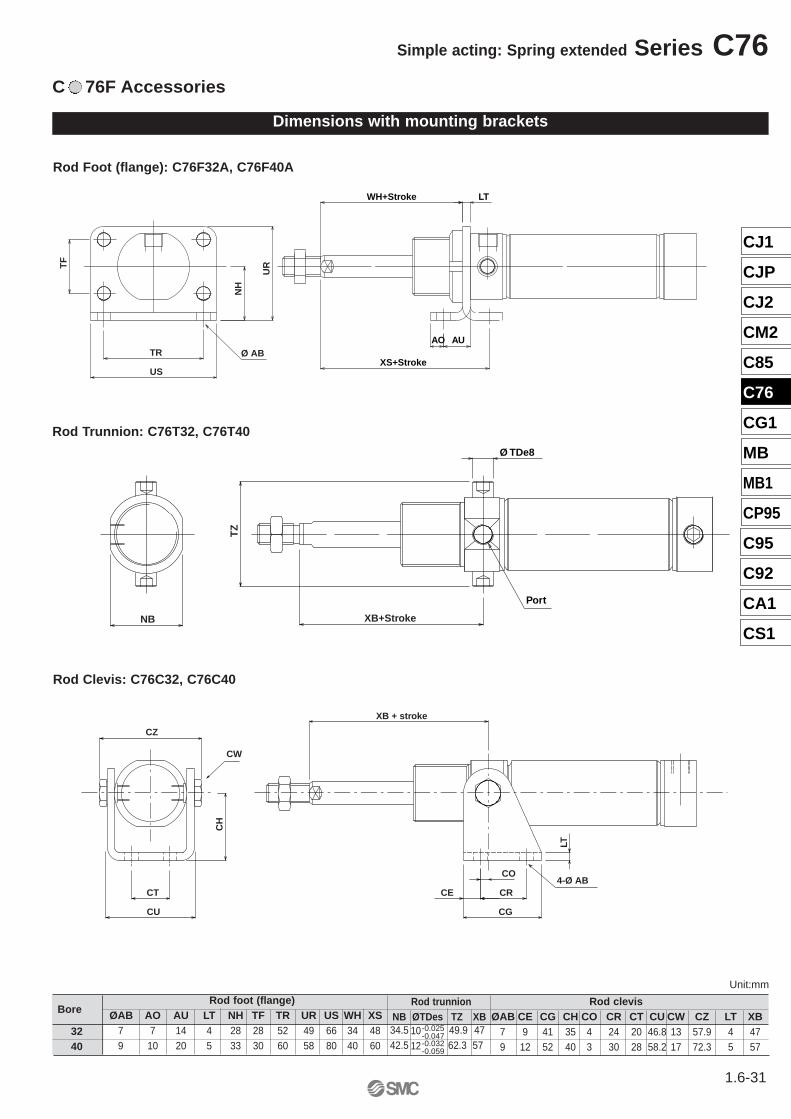
C 76F Accessories
Rod Foot (flange): C76F32A, C76F40A
Rod Trunnion: C76T32, C76T40
Rod Clevis: C76C32, C76C40
Rod clevisØAB CE CG CH CO CR CT CU CW CZ LT XB
7 9 41 35 4 24 20 46.8 13 57.9 4 479 12 52 40 3 30 28 58.2 17 72.3 5 57
Rod trunnionNB ØTDes TZ XB34.5 49.9 4742.5 62.3 57
Rod foot (flange)ØAB AO AU LT NH TF TR UR US WH XS
7 7 14 4 28 28 52 49 66 34 489 10 20 5 33 30 60 58 80 40 60
Bore
1012
-0.025-0.047-0.032-0.059
3240
AO
XS+Stroke
AU
LTWH+Stroke
US
TR Ø AB
TF
NH
UR
TZ
XB+Stroke
Ø TDe8
Port
NB
4-Ø AB
CW
CO
CRCT
XB + stroke
CG
CE
CU
CH
CZ
LT
Unit:mm
1.6-31
Simple acting: Spring extended Series C76
CJ1
CJP
CJ2
CM2
C85
C76
CG1
MB
MB1
CP95
C95
C92
CA1
CS1
1.6-32
Series C76 Simple acting: Sprin Return/ Spring extended
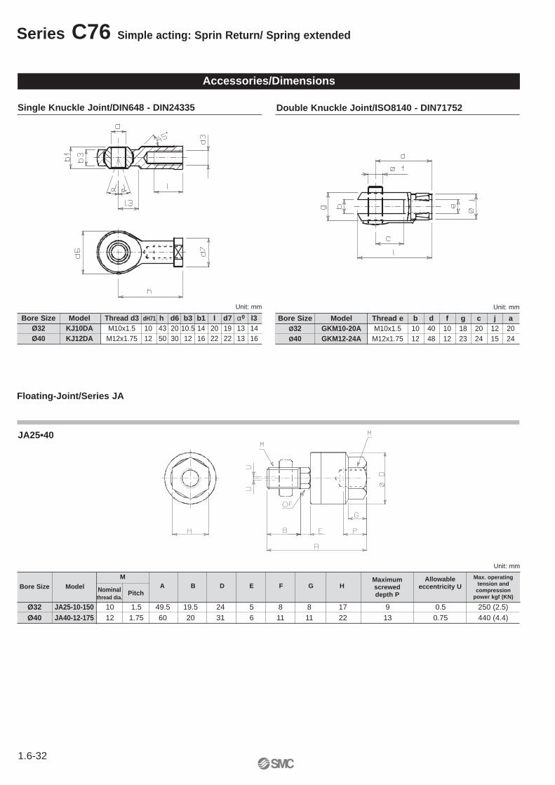
Accessories/Dimensions
Single Knuckle Joint/DIN648 - DIN24335 Double Knuckle Joint/ISO8140 - DIN71752
Floating-Joint/Series JA
Bore Size Model Thread d3 dH71 h d6 b3 b1 l d7 α0 l3Ø32 KJ10DA M10x1.5 10 43 20 10.5 14 20 19 13 14Ø40 KJ12DA M12x1.75 12 50 30 12 16 22 22 13 16
Unit: mm Unit: mm
Bore Size Model Thread e b d f g c j aØ32 GKM10-20A M10x1.5 10 40 10 18 20 12 20Ø40 GKM12-24A M12x1.75 12 48 12 23 24 15 24
M
Ø32 JA25-10-150 10 1.5 49.5 19.5 24 5 8 8 17 9 0.5 250 (2.5)Ø40 JA40-12-175 12 1.75 60 20 31 6 11 11 22 13 0.75 440 (4.4)
Unit: mm
Nominalthread dia.
Maximum screweddepth P
Allowableeccentricity UA B D E F G HBore Size Model
Pitch
Max. operatingtension and
compressionpower kgf (KN)
JA25•40
Reed Switch Setting Position (Stroke End)(Band Mounted Type) (Rail Mounted Type)
D-C73LD-C80L
D-A73LD-A80L
D-C73CND-C80CN
D-A73HLD-A80HL
D-A73CND-A80CN
D-A79WL
1.6-33
Standard: Double Acting Single Rod Series C76
CJ1
CJP
CJ2
CM2
C85
C76
CG1
MB
MB1
CP95
C95
C92
CA1
CS1
Band Mounted TypeNo. of auto switches
Auto switch 2pcs. npcs. 1pc.model Different Same Different Same
orientation orientation orientation orientationD-C73L
15 5015+45 50+45(n-2)
10D-C80L (n=2,4...)
D-C73CN15 65
15+50 65+50(n-2)10
D-C80CN (n=2,4...)
( n-2 )2
( n-2 )2
Auto Switch Mounting, Minimum Possible Cylinder Strokes
Rail Mounted TypeNo. of auto switches
Auto switch 2pcs. npcs. 1pc.model Different Same Different Same
orientation orientation orientation orientationD-A73L, D-A80L,
10+35D-A73HL, D-A80HL, — 10 — 5D-A73CN, D-A80CN
(n=2,4...)
D-A79WL — 15 —15+35
10(n=2,4...)
( n-2 )2
( n-2 )2
Unit:mm
Auto Bore Single acting/Spring return Single acting/Spring extendedswitch size A
B AB Hs
model 1÷50st 51÷100st 101÷150st 151÷200st 201÷250st 1÷50st 51÷100st 101÷150st 151÷200st 201÷250stD-C73L 32 8(33) 58 83 108 — 7 8 32 57 82 107 — 28.5D-C80L 40 13(38) 63 88 113 138 12 13 37 62 87 112 137 32.5
D-C73CN 32 8(33) 58 83 108 — 7 8 32 57 82 107 — 31D-C80CN 40 13(38) 63 88 113 138 12 13 37 62 87 112 137 35D-A73L 32 9(34) 59 84 109 — 1 9 33 58 83 108 — 29.3D-A80L 40 14(39) 64 89 114 139 6 14 38 63 88 113 138 33.8
D-A73HL 32 9(34) 59 84 109 — 8 9 33 58 83 108 — 30.3D-A80HL 40 14(39) 64 89 114 139 13 14 38 63 88 113 138 34.8D-A73CN 32 9(34) 59 84 109 — 8 9 33 58 83 108 — 36.2D-A80CN 40 14(39) 64 89 114 139 13 14 38 63 88 113 138 40.7
D-A79WL32 6(31) 56 81 106 — 5 6 30 55 80 105 — 31.640 11(36) 61 86 111 136 10 11 35 60 85 110 135 36.1
( ): In case of non-rotating
1.6-34
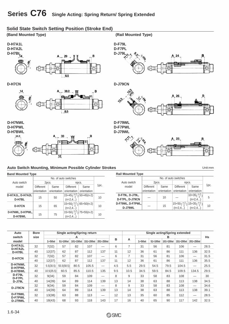
Series C76 Single Acting: Spring Return/ Spring Extended
Solid State Switch Setting Position (Stroke End)(Band Mounted Type) (Rail Mounted Type)
D-H7A1LD-H7A2LD-H7BL
D-F79LD-F7PLD-J79L
D-H7CN D-J79CN
D-H7NWLD-H7PWLD-H7BWL
D-F79WLD-F7PWLD-J79WL
Band Mounted TypeNo. of auto switches
Auto switch 2pcs. npcs. 1pc.model Different Same Different Same
orientation orientation orientation orientationD-H7A1L, D-H7A2L
15 5015+45 50+45(n-2)
10D-H7BL (n=2,4...)
D-H7CN 15 6515+50 65+50(n-2)
10(n=2,4...)
D-H7NWL, D-H7PWL,15 75
15+50 75+55(n-2)10
D-H7BWL (n=2,4...)
( n-2 )2
( n-2 )2
Auto Switch Mounting, Minimum Possible Cylinder Strokes
Rail Mounted TypeNo. of auto switches
Auto switch 2pcs. npcs. 1pc.model Different Same Different Same
orientation orientation orientation orientationD-F79L, D-J79L,
— 10 —10+35
5D-F7PL, D-J79CN (n=2,4...)
D-F79WL, D-F7PWL,— 15
15+50 15+3510
D-J79WL (n=2,4...) (n=2,4...)
( n-2 )2
( n-2 )2
Unit:mm
Auto Bore Single acting/Spring return Single acting/Spring extendedswitch size A
B AB Hs
model 1÷50st 51÷100st 101÷150st 151÷200st 201÷250st 1÷50st 51÷100st 101÷150st 151÷200st 201÷250st
32 7(32) 57 82 107 — 6 7 31 56 81 106 — 28.5
40 12(37) 62 87 112 137 11 12 36 61 86 111 136 32.5
D-H7CN32 7(32) 57 82 107 — 6 7 31 56 81 106 — 31.5
40 12(37) 62 87 112 137 11 12 36 61 86 111 136 35.5
32 5.5(30.5) 55.5(58.5) 80.5 105.5 — 4.5 5.5 29.5 54.5 79.5 104.5 — 25.5
40 10.5(35.5) 60.5 85.5 110.5 135 9.5 10.5 34.5 59.5 84.5 109.5 134.5 29.5
32 9(34) 59 84 109 — 8 9 33 58 83 108 — 30
40 14(39) 64 89 114 139 13 14 38 63 88 113 138 34.5
D-J79CN32 9(34) 59 84 109 — 8 9 33 58 83 108 — 34.640 14(39) 64 89 114 139 13 14 38 63 88 113 138 39.1
32 13(38) 63 88 113 — 12 13 35 60 85 112 — 28.5
40 18(43) 68 93 118 143 17 16 40 65 90 117 142 32.5
( n-2 )2
( n-2 )2
D-H7A1LD-H7A2LD-H7BL
D-H7NWLD-H7PWLD-H7BWL
D-F79LD-F7PLD-J79L
D-F79WLD-F7PWLD-J79WL
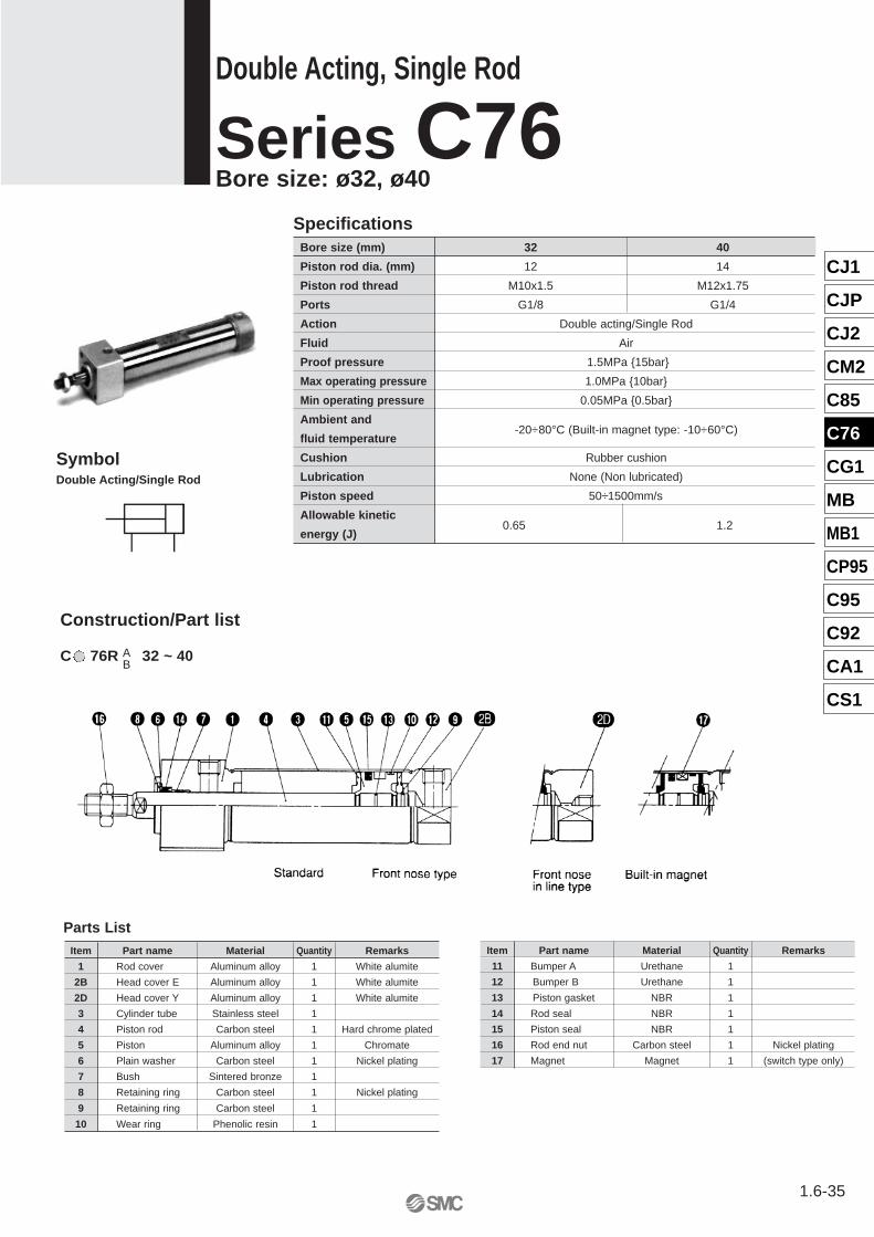
C 76R 32 ~ 40
Construction/Part list
AB
CJ1
CJP
CJ2
CM2
C85
C76
CG1
MB
MB1
CP95
C95
C92
CA1
CS1
1.6-35
Double Acting, Single Rod
Series C76 Bore size: ø32, ø40
Bore size (mm) 32 40
Piston rod dia. (mm) 12 14
Piston rod thread M10x1.5 M12x1.75
Ports G1/8 G1/4
Action Double acting/Single Rod
Fluid Air
Proof pressure 1.5MPa {15bar}
Max operating pressure 1.0MPa {10bar}
Min operating pressure 0.05MPa {0.5bar}
Ambient and-20÷80°C (Built-in magnet type: -10÷60°C)
fluid temperature
Cushion Rubber cushion
Lubrication None (Non lubricated)
Piston speed 50÷1500mm/s
Allowable kinetic0.65 1.2
energy (J)
Specifications
SymbolDouble Acting/Single Rod
Parts ListItem Part name Material Quantity Remarks
1 Rod cover Aluminum alloy 1 White alumite
2B Head cover E Aluminum alloy 1 White alumite
2D Head cover Y Aluminum alloy 1 White alumite
3 Cylinder tube Stainless steel 1
4 Piston rod Carbon steel 1 Hard chrome plated
5 Piston Aluminum alloy 1 Chromate
6 Plain washer Carbon steel 1 Nickel plating
7 Bush Sintered bronze 1
8 Retaining ring Carbon steel 1 Nickel plating
9 Retaining ring Carbon steel 1
10 Wear ring Phenolic resin 1
Item Part name Material Quantity Remarks
11 Bumper A Urethane 1
12 Bumper B Urethane 1
13 Piston gasket NBR 1
14 Rod seal NBR 1
15 Piston seal NBR 1
16 Rod end nut Carbon steel 1 Nickel plating
17 Magnet Magnet 1 (switch type only)
1.6-36
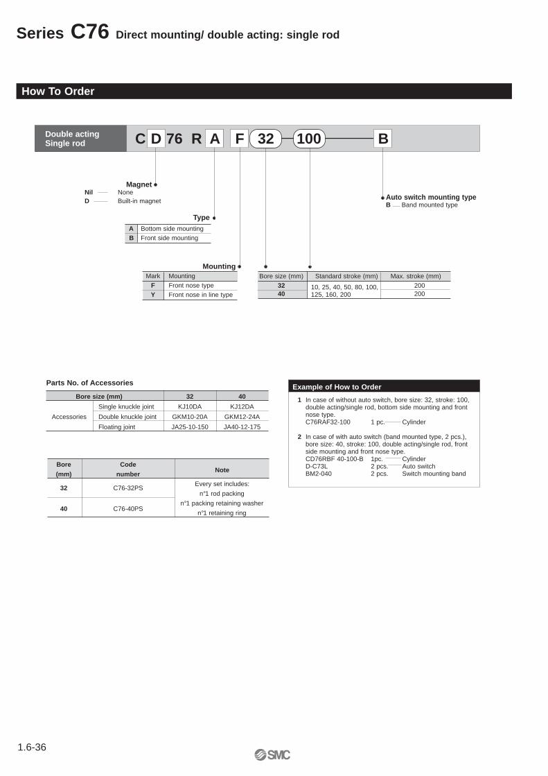
Series C76 Direct mounting/ double acting: single rod
How To Order
Double actingSingle rod
Auto switch mounting typeB Band mounted type
TypeA Bottom side mounting
B Front side mounting
MountingMark Mounting
F Front nose type
Y Front nose in line type10, 25, 40, 50, 80, 100,125, 160, 200
MagnetNil NoneD Built-in magnet
C D 76 R A F 32 100 B
Parts No. of Accessories Example of How to Order
1 In case of without auto switch, bore size: 32, stroke: 100,double acting/single rod, bottom side mounting and frontnose type.C76RAF32-100 1 pc. Cylinder
2 In case of with auto switch (band mounted type, 2 pcs.),bore size: 40, stroke: 100, double acting/single rod, frontside mounting and front nose type.CD76RBF 40-100-B 1pc. CylinderD-C73L 2 pcs. Auto switchBM2-040 2 pcs. Switch mounting band
Bore size (mm) 32 40
Single knuckle joint KJ10DA KJ12DA
Accessories Double knuckle joint GKM10-20A GKM12-24A
Floating joint JA25-10-150 JA40-12-175
Bore size (mm) Standard stroke (mm) Max. stroke (mm)
32 20040 200
Bore Code Note
(mm) number
Every set includes:32 C76-32PS
n°1 rod packing
40 C76-40PSn°1 packing retaining washer
n°1 retaining ring
1.6-37
Direct mounting/ double acting: single rod Series C76
CJ1
CJP
CJ2
CM2
C85
C76
CG1
MB
MB1
CP95
C95
C92
CA1
CS1
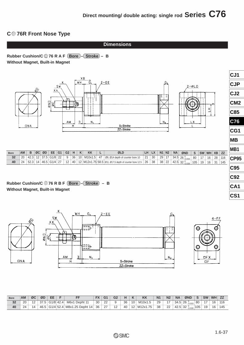
Rubber Cushion/C 76 R A F Bore – Stroke – B Without Magnet, Built-in Magnet
C 76R Front Nose Type
Dimensions
AM B ØC ØD EE G1 G2 H K KK L ØLD LH LX N1 N2 NA20 42.3 12 37.5 G1/8 22 9 36 10 M10x1.5 47 Ø9, Ø14 depth of counter bore 10 21 30 29 17 34.524 52.3 14 46.5 G1/4 27 12 40 12 M12x1.75 58.5 Ø11, Ø17.5 depth of counter bore 12.5 26 38 38 22 42.5
Bore
32 40
Bore
32 40
AM ØC ØD EE F FF FX G1 G2 H K KK N1 N2 NA ØND S SW WH ZZ20 12 37.5 G1/8 42.4 M6x1 Depht 11 30 22 9 36 10 M10x1.5 29 17 34.5 26 80 17 16 11624 14 46.5 G1/4 52.4 M8x1.25 Depht 14 36 27 12 40 12 M12x1.75 38 22 42.5 32 105 19 16 145
ØND S SW WH XB ZZ26 80 17 16 28 11632 105 19 16 31 1450
-0.039
0-0.033
Rubber Cushion/C 76 R B F Bore – Stroke – B Without Magnet, Built-in Magnet
0-0.039
0-0.033
1.6-38
Series C76 Direct mounting/ double acting: single rod
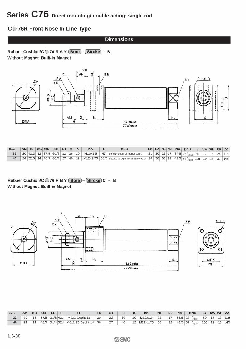
C 76R Front Nose In Line Type
Dimensions
AM B ØC ØD EE G1 H K KK L ØLD LH LX N1 N2 NA20 42.3 12 37.5 G1/8 22 36 10 M10x1.5 47 Ø9, Ø14 depth of counter bore 1 21 30 29 17 34.524 52.3 14 46.5 G1/4 27 40 12 M12x1.75 58.5 Ø11, Ø17.5 depth of counter bore 12.5 26 38 38 22 42.5
Bore
32 40
Bore
32 40
AM ØC ØD EE F FF FX G1 H K KK N1 N2 NA ØND S SW WH ZZ20 12 37.5 G1/8 42.4 M6x1 Depht 11 30 22 36 10 M10x1.5 29 17 34.5 26 80 17 16 11624 14 46.5 G1/4 52.4 M8x1.25 Depht 14 36 27 40 12 M12x1.75 38 22 42.5 32 105 19 16 145
Rubber Cushion/C 76 R A Y Bore – Stroke – B Without Magnet, Built-in Magnet
ØND S SW WH XB ZZ26 80 17 16 28 11632 105 19 16 31 1450
-0.039
0-0.033
Rubber Cushion/C 76 R B Y Bore – Stroke C – B Without Magnet, Built-in Magnet
0-0.039
0-0.033
1.6-39
Direct mounting/ double acting: single rod Series C76
CJ1
CJP
CJ2
CM2
C85
C76
CG1
MB
MB1
CP95
C95
C92
CA1
CS1
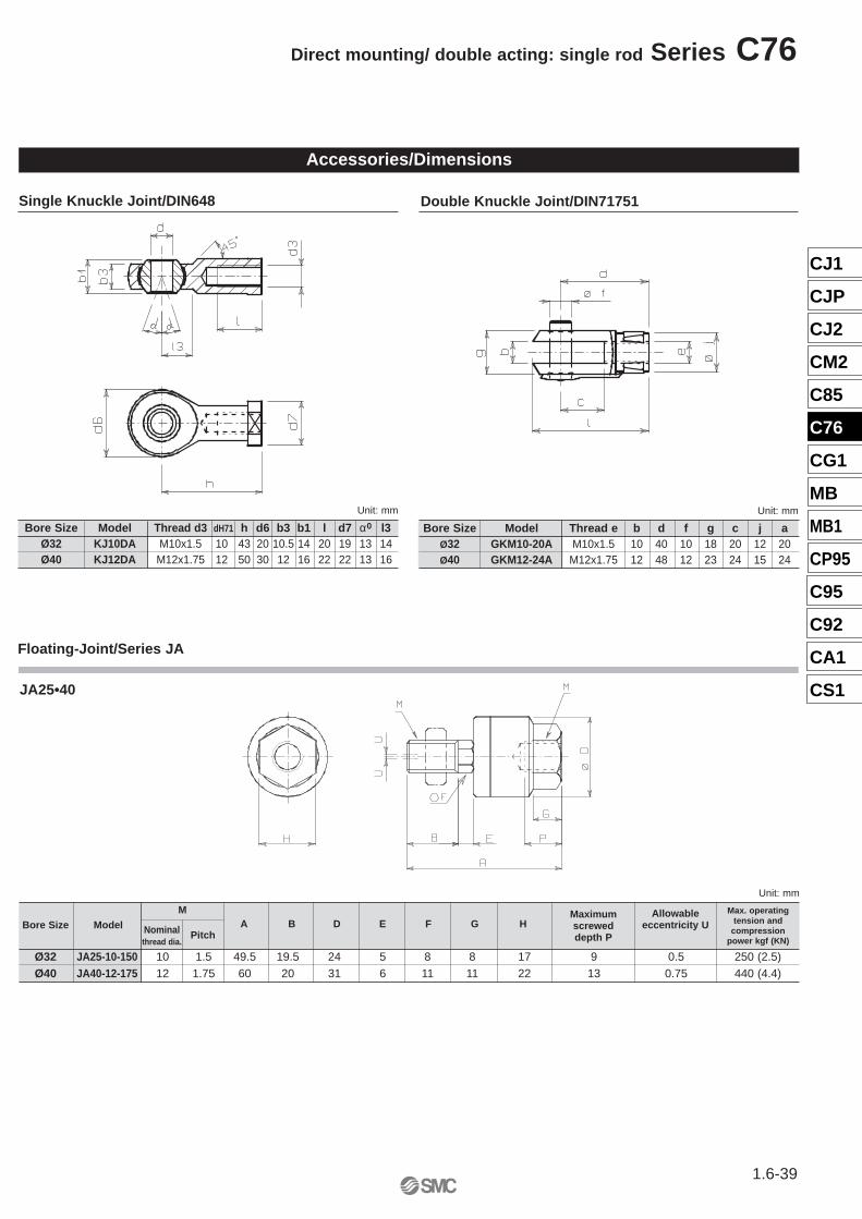
Accessories/Dimensions
Single Knuckle Joint/DIN648 Double Knuckle Joint/DIN71751
Floating-Joint/Series JA
Bore Size Model Thread d3 dH71 h d6 b3 b1 l d7 α0 l3Ø32 KJ10DA M10x1.5 10 43 20 10.5 14 20 19 13 14Ø40 KJ12DA M12x1.75 12 50 30 12 16 22 22 13 16
Unit: mm Unit: mm
Bore Size Model Thread e b d f g c j aØ32 GKM10-20A M10x1.5 10 40 10 18 20 12 20Ø40 GKM12-24A M12x1.75 12 48 12 23 24 15 24
M
Ø32 JA25-10-150 10 1.5 49.5 19.5 24 5 8 8 17 9 0.5 250 (2.5)Ø40 JA40-12-175 12 1.75 60 20 31 6 11 11 22 13 0.75 440 (4.4)
Unit: mm
Nominalthread dia.
Maximum screweddepth P
Allowableeccentricity UA B D E F G HBore Size Model
Pitch
Max. operatingtension and
compressionpower kgf (KN)
JA25•40
1.6-40
Series C76 Direct mounting/ double acting: single rod
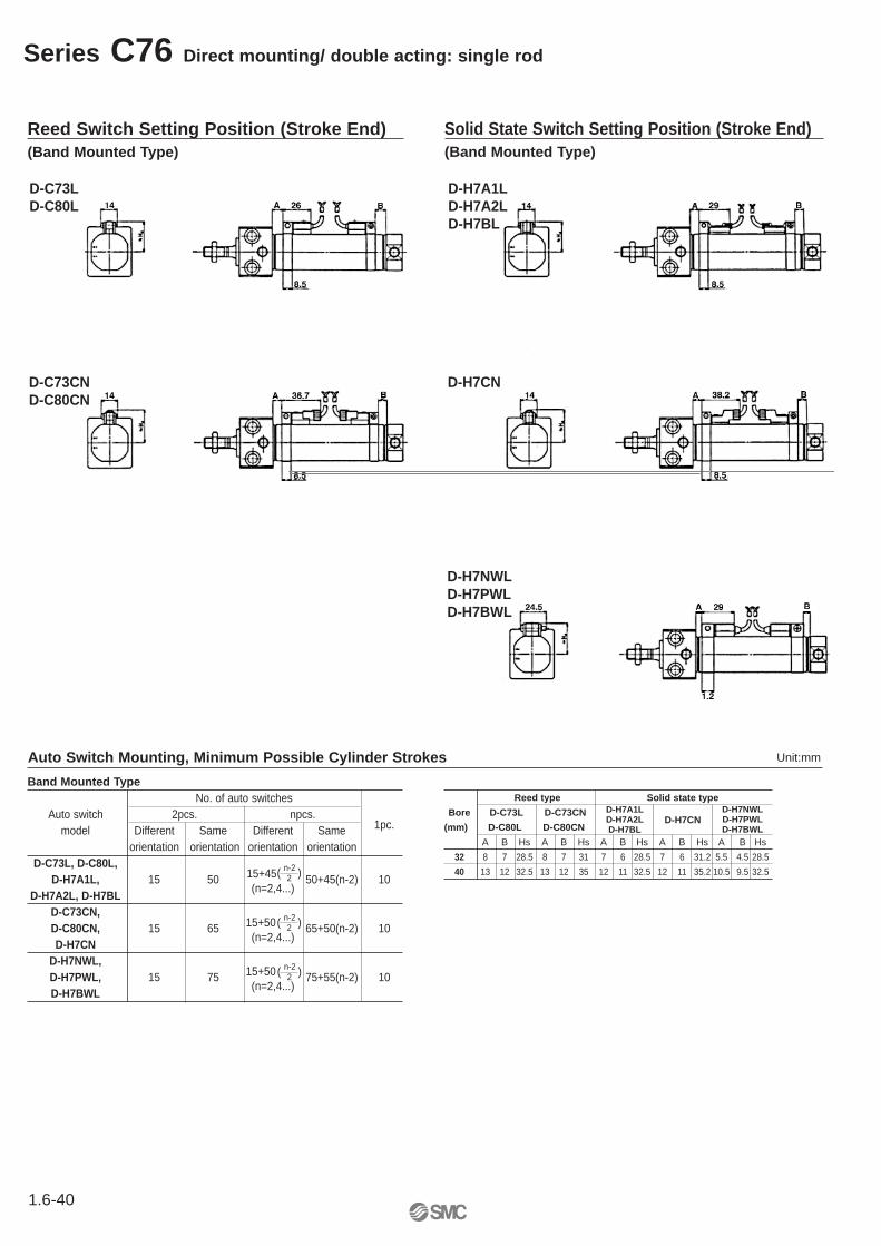
Reed Switch Setting Position (Stroke End)(Band Mounted Type)
D-C73LD-C80L
D-H7A1LD-H7A2LD-H7BL
D-C73CND-C80CN
D-H7CN
D-H7NWLD-H7PWLD-H7BWL
Solid State Switch Setting Position (Stroke End)(Band Mounted Type)
Band Mounted TypeNo. of auto switches
Auto switch 2pcs. npcs. 1pc.model Different Same Different Same
orientation orientation orientation orientationD-C73L, D-C80L,
15+45D-H7A1L, 15 50 50+45(n-2) 10D-H7A2L, D-H7BL
(n=2,4...)
D-C73CN, 15+50D-C80CN, 15 65 65+50(n-2) 10
D-H7CN(n=2,4...)
D-H7NWL,15+50D-H7PWL, 15 75 75+55(n-2) 10
D-H7BWL(n=2,4...)
( n-2 )2
( n-2 )2
( n-2 )2
Auto Switch Mounting, Minimum Possible Cylinder Strokes
Reed type Solid state type
Bore D-C73L D-C73CN D-H7CN
(mm) D-C80L D-C80CN
A B Hs A B Hs A B Hs A B Hs A B Hs
32 8 7 28.5 8 7 31 7 6 28.5 7 6 31.2 5.5 4.5 28.5
40 13 12 32.5 13 12 35 12 11 32.5 12 11 35.2 10.5 9.5 32.5
Unit:mm
D-H7A1LD-H7A2LD-H7BL
D-H7NWLD-H7PWLD-H7BWL


![Air Cushion Vehicles [Bertelsen] Collection · Box 2, Folder 4 Notebook 13: Arcopter GEM-2 Research Manual, April 30, 1962 Series 1: Notebooks, Photographs, and Writings Air Cushion](https://img.pdfslide.us/doc/110x75/602b727a2138be20c77df1ca/air-cushion-vehicles-bertelsen-collection-box-2-folder-4-notebook-13-arcopter.jpg)


![Air Cushion Vehicles [Bertelsen] Collectionsirismm.si.edu/EADpdfs/NASM.1994.0013.pdf · · 2017-11-27Air Cushion Vehicles [Bertelsen] Collection NASM.1994.0013 Page 3 of 10 Series](https://img.pdfslide.us/doc/110x75/5ae8c3757f8b9ac3618b8e3a/air-cushion-vehicles-bertelsen-cushion-vehicles-bertelsen-collection-nasm19940013.jpg)