Embed Size (px)
Citation preview
8/12/2019 c64 Programmers Reference Guide 04 Programming Sound
http://slidepdf.com/reader/full/c64-programmers-reference-guide-04-programming-sound 1/26
8/12/2019 c64 Programmers Reference Guide 04 Programming Sound
http://slidepdf.com/reader/full/c64-programmers-reference-guide-04-programming-sound 2/26
8/12/2019 c64 Programmers Reference Guide 04 Programming Sound
http://slidepdf.com/reader/full/c64-programmers-reference-guide-04-programming-sound 3/26
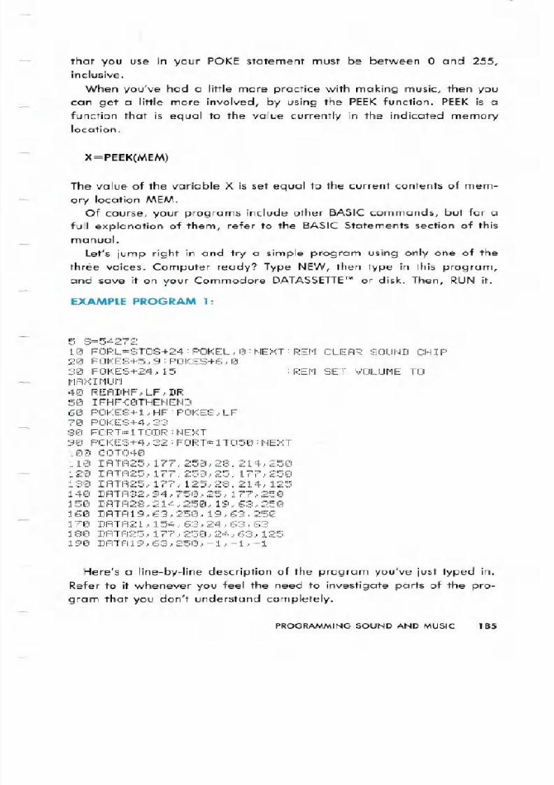
that you use in your POKE statement must be between 0 and 255,inclusive.
When you ve had a little more practice with making music, then you
can get a little more involved, by using the PEEKfunction. PEEK is a
function that is equal to the value currently in the indicated memorylocation.
X=PEEK MEM)
The value of the variable X is set equal to the current contents of mem-
ory location MEM.
Of course, your programs include other BASIC commands, but for afull explanation of them, refer to the BASIC Statements section of this
manual.
Let s jump right in and try a simple program using only one of the
three voices. Computer ready? Type NEW, then type in this program,
and save it on your Commodore DATASSETTETMr disk. Then, RUN it.
X MPL PROGRAM
5 ~:;=5427210 FORL=STOS+24:POKEL,0:NEXT:REM CLEAR SOUND CHIP
20 POKE:::+5, 9 :PC1f(ES+6., °
30 POKES+24,15 :REM SET VOLUME TOr tA: :r1Ur1
40 READHF, LF . DR
50 IFHF(0THENEND
60 POKES+l,HF:POKES,LF
70 POKES+4., ::;::::;:
80 FORT=ITODR:NEXT
90 POKES+4,32:FORT=IT050:NEXT100 CiOT04r21
110 DATA25,177,250,28,214,250 2 DATA25J 77J25 J25J 77J25
130 DATA25,177,125,28,214,125140 DATA32,94,750,25,177,250150 DATA28,214,250,19,63,250
160 DATAI9,63,250,19,63,250170 DATA21.154,63,24,63,63180 DATA25,177,250,24,63,125190 DATA19,63,250,-1,-1,-1
Here s a line-by-line description of the program you ve just typed in.
Refer to it whenever you feel the need to investigate parts of the pro-
gram that you don t understand completely.
PROGRAMMING SOUND AND MUSIC 8
8/12/2019 c64 Programmers Reference Guide 04 Programming Sound
http://slidepdf.com/reader/full/c64-programmers-reference-guide-04-programming-sound 4/26
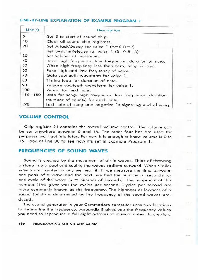
LINE BYLINE EXPL N TIONOF EX MPLEPROGR M
VOLUME CONTROL
Chip register 24 contains the overall volume control. The volume can
be set anywhere between ° and 15. The other four bits are used for
purposes we ll get into later. For now it is enough to know volume is 0 to
15. Look at line 30 to see how it s set in Example Program 1.
FREQUENCIES OF SOUND WAVES
Sound is created by the movement of air in waves. Think of throwing
a stone into a pool and seeing the waves radiate outward. When similar
waves are created in air, we hear it. If we measure the time between
one peak of a wave and the next, we find the number of seconds for
one cycle of the wave n = number of seconds). The reciprocal of this
number 1/n) gives you the cycles per second. Cycles per second are
more commonly known as the frequency. The highness or lowness of a
sound pitch) is determined by the frequency of the sound waves pro-duced.
The sound generator in your Commodore computer uses two locations
to determine the frequency. Appendix E gives you the frequency values
you need to reproduce a full eight octaves of musical notes. To create a
186 PROGRAMMING SOUND AND MUSIC
Line s) Description
5
Set S to start of sound chip.10 Clear all sound chip registers.20 Set Attack/Decay for voice 1 A=0,D=9). I
Set Sustain/Release for voice 1 S=O,R=O).30 Set volume at maximum.
40 Read high frequency, low frequency, duration of note.50 When high frequency less than zero, song is over.60 Poke high and low frequency of voice 1.70 Gate sawtooth waveform for voice 1.
80 Timing loop for duration of note.90 Release sawtooth waveform for voice 1.100 Return for next note.
110- 180 Data for song: high frequency, low frequency, duration
number of counts) for each note.190 . Last note of song and negative 1s signaling end of song.
8/12/2019 c64 Programmers Reference Guide 04 Programming Sound
http://slidepdf.com/reader/full/c64-programmers-reference-guide-04-programming-sound 5/26
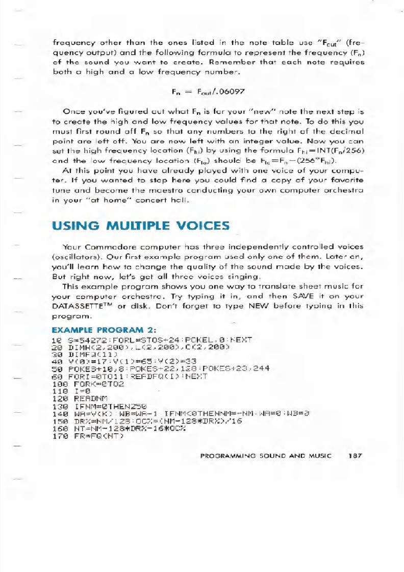
frequency other than the ones listed in the note table use Fout (fre-
quency output) and the following formula to represent the frequency (Fn)
of the sound you want to create. Remember that each note requires
both a high and a low frequency number.
Fn = Fout/.06097
Once you've figured out what Fnis for your new note the next step is
to create the high and low frequency values for that note. Todo this you
must first round off Fn so that any numbers to the right of the decimal
point are left off. You are now left with an integer value. Now you can
set the high frequency location (Fhi)by using the formula Fhi=INT(Fn/256)
and the low frequency location (Flo) should be Flo=Fn-(256*Fhi).
At this point you have already played with one voice of your compu-
ter. If you wanted to stop here you could find a copy of your favorite
tune and become the maestro conducting your own computer orchestra
in your at home concert hall.
USIN MULTIPLEVOI ES
Your Commodore computer has three independently controlled voices
(oscillators). Our first example program used only one of them. Later on,
you'll learn how to change the quality of the sound made by the voices.
But right now, let's get all three voices singing.
This example program shows you one way to translate sheet music for
your computer orchestra. Try typing it in, .and then SAVE it on your
DATASSETTeMor disk. Don't forget to type NEW before typing in this
program.EX MPLEPRO R M2:
10 8=54272: FORL=STOS+24: POKEL,10:NE>(T20 D1MH(2,200),L(2,200),C(2,200)30 DII1FQ(11)40 V(0)=17:V(1)=65:V(2)=3350 POKES+10,8:POKES+22,128:POKES+23,24460 FOR1=0T011:READFQ(1):NEXT1'21'21FORK=0T02
110 1=0
120 READt'IM130 IFNM=0THEN250140 WA=V(K):WB=WA-l:1FNM(0THENNM=-NM:WA=0:WB=0150 DR =NM/128:0C =(NM-128*DR )/16160 NT=NM-128~DR -16*OC170 FR=FQ(tH)
PROGRAMMINGOUNDANDMUSIC 8
8/12/2019 c64 Programmers Reference Guide 04 Programming Sound
http://slidepdf.com/reader/full/c64-programmers-reference-guide-04-programming-sound 6/26
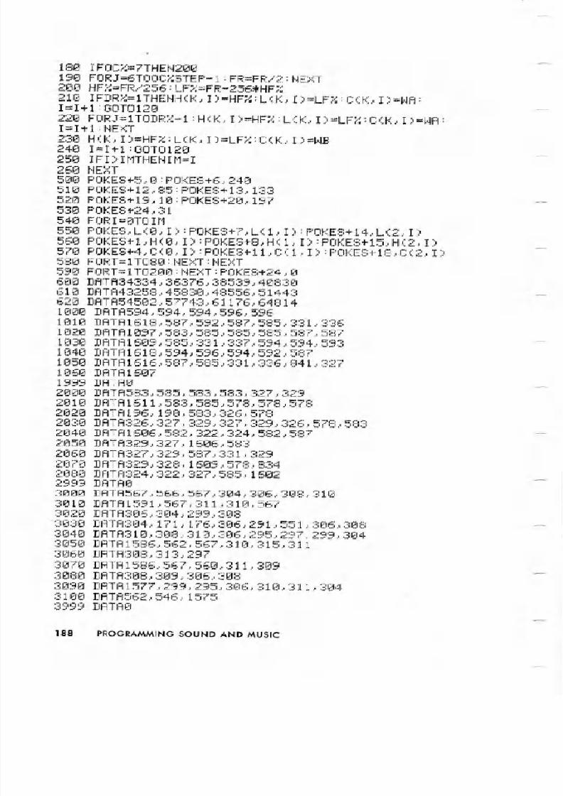
180 IFOC =7THEN200190 FORJ=6TOOCr.STEP-1:FR=FR/2:NEXT200 HF =FR/256:LF =FR-256*HFr.210IFDRr.=1THENHCK,I)=HFr.:LCK,I)=LFr.:C<.K,I)=WA:
I=I+l:00TOI20220 FORJ=ITODR -l:HCK,I)=HFr.:L K,I)=LF :C K,I)=WA:I=I+l:NEXT230 H K,I)=HFr.:L K,I)=LF :CCK,I)=WB24 I=I+l:00T0120250 IFI)IMTHENIM=I26 NEXT
500 POKES+5,0:POKES+6,240510 POKES+12,85:POKES+13,133520 POKES+19,10:POKES+20, 197530 POKES+24,31
540 FORI=0TOIM550 POKES,L 0,I):POKES+7,LC1,I):POKES+14,L 2,I)560 POKES+l,H 0,I):POKES+8,H 1,I):POKES+15,H 2,I)570 POKES+4,C 0,I):POKES+ll,CCl,I):POKES+18,C 2,I)580 FORT=lT080:NEXT:NEXT590 FORT=lT0200:NEXT:POKES+24,0600 DATA34334,36376,38539,40830610 DATA43258,45830,48556,51443620 DATA54502,57743,61176,648141000 DATA594,594,594,596,5961010 DATA1618,587,592,587,585,331,336
1020 DATA1097,583,585,585,585,587,5871030 DATA1609,585,331,337,594,594,5931040 DATA1618,594,596,594,592,5871050 DATA1616,587,585,331,336,841,3271060 DATA16071999 DATA02000 DATA583,585,583,583,327,3292010 DATA1611,583,585,578,578,5782 2 DATA196 198 583 326 578
2 3 DATA326 327 329 327 329 326 578 583
2 4 DATA16 6 582 322 324 582 587
2 5 DATA329 327 16 6 5832 6 DATA327 329 587 331 329
2 7 DATA329 328 16 9 578 8342 8 DATA324 322 327 585 16022999 DATA
3 DATA567 566 567 3 4 3 6 3 8 313 1 DATA1591 567 311 31 5673 2 DATA3 6 3 4 299 3 8
3 3 DATA3 4 171 176 3 6 291 551 3 6 3 8
3 4 DATA31 3 8 31 3 6 295 297 299 3 43 5 DATA1586 562 567 31 315 311
3 6 DATA3 8 313 2973 7 DATA1586,567,560,311,3093 8 DATA3 8 3 9 3 6 3 8
3 9 DATA1577 299 295 3 6 31 311 3 4
31 DATA562 546 15753999 DATA
PROGRAMMING SOUND ND MUSI

8/12/2019 c64 Programmers Reference Guide 04 Programming Sound
http://slidepdf.com/reader/full/c64-programmers-reference-guide-04-programming-sound 7/26
Here is a line-by-line explanation of Example .Program 2. For now, we
are interested in how the thre.e voices .are controlled.
LlNE BY LiNEEXPL N TIONOF EX MPLEPROGR M
10
20
30
40
50
60
100
no
120
130
140
150
160
170
180
190
200
210
220
230
240
250
260500
line s) Description
Set S equal to start of sound chip and clear all. sound
chip registers.
Dimension arrays to contain activity of song, l/l6th of a
measure per lo.cation.
Dimension array to contain base frequency for each note.
Store waveform control byte for each voice.
Set high pulse width for voice 2.
Set high frequency for filter cutoff.Set resonance for filter and filter voice 3.
Read in base frequency for each note.
Begin decoding loop for each voice.
Initialize pointer to activity array.
Read coded note .
If coded note is zero, then r: ext ,voice.
Set waveform controls. to proper voice.If silence, set waveform controls to. O.Decode duration and octave.
Decode note.
Get base frequency for this note.IIf highest octave, skip division loop.
Divide base frequency by 2 appropriate number of times.
Get high and low frequency bytes.
If sixteenth no.te, set activity array: high frequency, lowfrequency, and: waveform control voice on).
For all but last beat of note, set activity array: high
frequency, low frequency, waveform control voice on).
For last be.at of note, set activity array: high frequency,
low frequency, waveform control voice off).
Increment pointer to activity array. Get next note.
If longer t~an before, reset number of activities.
Go back for next voice.Set Attack/Decay for voicel A=O, D=O)..
Set Sustain/Release for voice 1 S=15, R=O).
PROGRAMMING SOUND AND MUSIC 9
8/12/2019 c64 Programmers Reference Guide 04 Programming Sound
http://slidepdf.com/reader/full/c64-programmers-reference-guide-04-programming-sound 8/26
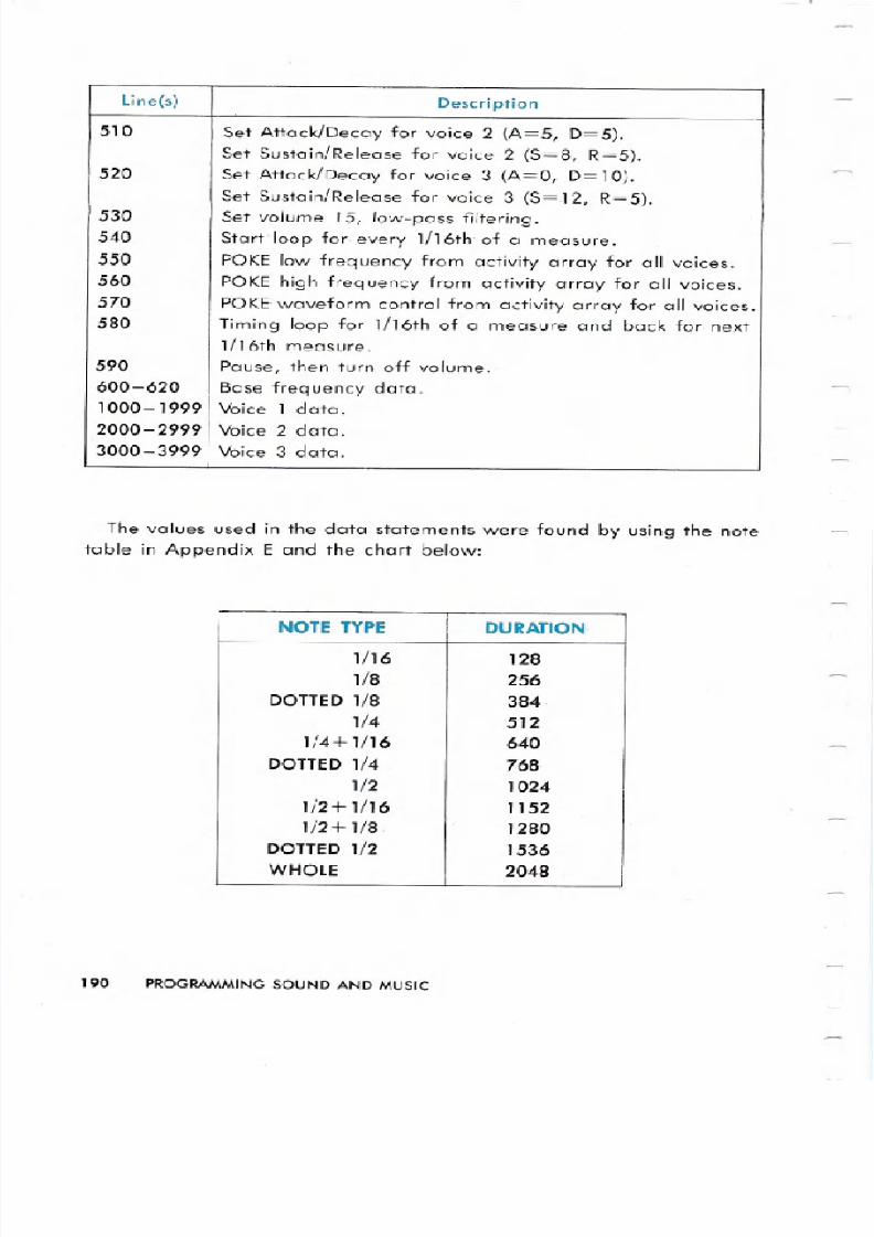
The values used in the data statements were found by using the note
table in Appendix E and the chart below:
190 PROGRAMMING SOUND AND MUSIC
line s Description
510 Set Attack/Decay for voice 2 A=5, D=5 .
Set Sustain/Release for voice 2 S=8, R=5 .
520 Set Attack/Decay for voice 3 A=O, D= 10 .
Set Sustain/Release for voice 3 S=12, R=5 .530 Set volume 15, low-pass filtering.540 Start loop for every 1/16th of a measure.550 POKE low frequency from activity array for all voices.560 POKE-high frequency from activity array for all voices.570 POKE-waveform control from activity array for all voices.580 Timing loop for 1/16th of a measure and back for next
1/16th measure.590 Pause, then turn off volume.600-620 Base frequency data.1000-1999 Voice 1 data.
2000-2999 Voice 2 data.
3000-3999 Voice 3 data.
NOTE TYPE UR TION
1/16 128
1/8 256
DOTTED1/8 384
1/4 512
1/4+ 1/16 640
DOTTED1/4 768
1/2 1024
1/2+ 1/16 1152
1/2+ 1/8- 1280
DOTTED1/2 1536
W OL 2048
8/12/2019 c64 Programmers Reference Guide 04 Programming Sound
http://slidepdf.com/reader/full/c64-programmers-reference-guide-04-programming-sound 9/26
The. note number from the no.te table is added to the duration above.
Then each note can be entered using only one number which is decoded
by your program. This is only one method of coding note values. You
may be able to come up with one with which you are more comfortable.
The formula used here for encoding a note is as follows:
1) The duration number of 1/16ths of a measure) is multiplied by 8.
2) The result of step 1 is added to the octave you ve chosen 0-7).
3) The result of step 2 is then multiplied by 16.
4) Add your note choice 0- 11) to the result of the operation in step3.
In other words:
««D*8)+O) *16)+N)
Where D = duration, 0 = octave, and N = note
A silence is obtained by using the negative of the duration number
number of 1/16ths of a measure * 128).
ONTROLLING MULTIPL VOI S
Once you have gotten used to using more than one voice, you will find
that the timing of the three voices needs to be coordinated. This is ac-
complished in this program by:
1) Divide each musical measure into 16 parts.
2) Store the events that occur in each 1/16th measure interval in three
separate arrays.
The high and low frequency bytes are calculated by dividing the fre-
quencies of the highest octave by two lines 180 and 190). The
waveform control byte is a start signal for beginning a note or continu-
ing a note that is already playing. It is a stop signal to end a note. Thewaveform choice is made once for each voice in line 40.
Again, this is only one way to control multiple voices. You may come
up with your own methods. However, you should now be able to take
any piece of sheet music and figure out the notes for all three voices.
PROGRAMMING SOUND AND MUSIC 191
8/12/2019 c64 Programmers Reference Guide 04 Programming Sound
http://slidepdf.com/reader/full/c64-programmers-reference-guide-04-programming-sound 10/26
H NGING W V FORMS
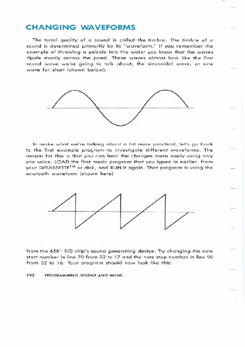
The tonal quality of a sound is called the tim re The timbre of a
sound is determined primarily by its waveform. If you remember theexample of throwing a pebble into the water you know that the waves
ripple evenly across the pond. These waves almost look like the first
sound wave we re going to talk about, the .sinusoidal wave, or sine
wave for short (shown below).
To make what we re talking about a bit more practical, let s go backto the first example program to investigate different waveforms. The
reason for this is that you can hear the changes more easily using only
one voice. LOADthe first .music program that you typed in earlier, from
your DATASSffiE™ or disk, and RUN it again. That program is using the
sawtooth waveform (shown here)
from the 6581 SID chip s sound generating device. Trychanging the note
start number in line 70 from 33 to 17 and the note stop nlJmber in line 90
from 32 to 16. Your program should now look like this:
192 PROGRAMMING SOUND ND MUSIC
8/12/2019 c64 Programmers Reference Guide 04 Programming Sound
http://slidepdf.com/reader/full/c64-programmers-reference-guide-04-programming-sound 11/26
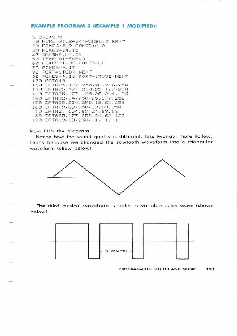
EXAMPLE PRO R M3 EXAMPLE1 MODIFIED :
5 ~3=5427:; ~
10 FORL=STOS 24:POKEL..0:NEXT
20 POKES 5..9:POKES 6..0::::121 POf<E~:; 24 15
40 REAIIHF LF.. IIF.:
50 IFHF<0THENEND60 POKES l..HF:POKES..LF
70 POKE::: 4. 17
80 FORT=lTODR:NEXT
90 POKES 4..16:FORT=IT050:NEXT
100 130T040
110 DATA25 177..250..28 214..250
120 DATA25..177..250..25..177..250
130 DATA25.. 177.. 125..28..214.. 125
140 DATA32..94.. 750.. 25.. 177 250
150 DATA28 214..250..19 63 250
160 DATAI9 63..250..19..63..250
170 DATA21 154 63..24..63 63
180 DATA25 177..250 24 63 125
190 DATAI9 63..250..-1 -I -1
Now RUN the program
Notice how the sound quality is different, less twangy, more hollow.
That s because we changed the sawtooth waveform into a triangular
waveform show below).
The third musical waveform is called a variable pulse wave shown
below).
PULSE WIDTH
PROGRAMMING SOUND AND MUSIC 193
8/12/2019 c64 Programmers Reference Guide 04 Programming Sound
http://slidepdf.com/reader/full/c64-programmers-reference-guide-04-programming-sound 12/26
It is a rectangular wave and you determine the length of the pulse
cycle by defining the proportion of the wave which will be high. This is
accomplished for voice 1 by using registers 2 and 3: Register 2 is the low
byte of the pulse width Lpw
=0 through 255). Register 3 is the high 4
bits Hpw = 0 through 15).Together these registers specify a 12-bit number for your pulse width,
which you can determine by using the following formula:
The pulse width is determined by the following equation:
PWout = Wn/40.95)
When PWn has a value of 2048, it will give you a square wave. That
means that register 2 Lpw)= 0 and register 3 Hpw)= 8.Now try adding this line to your program:
15 POKES 3 8:POKES 2 O
Then change the start number in line 70 to 65 and the stop number in
line 90 to 64, and RUN the program. Now change the high pulse widthregister 3 in line 15) from an 8 to a 1. Notice how dramatic the differ-
ence in sound quality is?
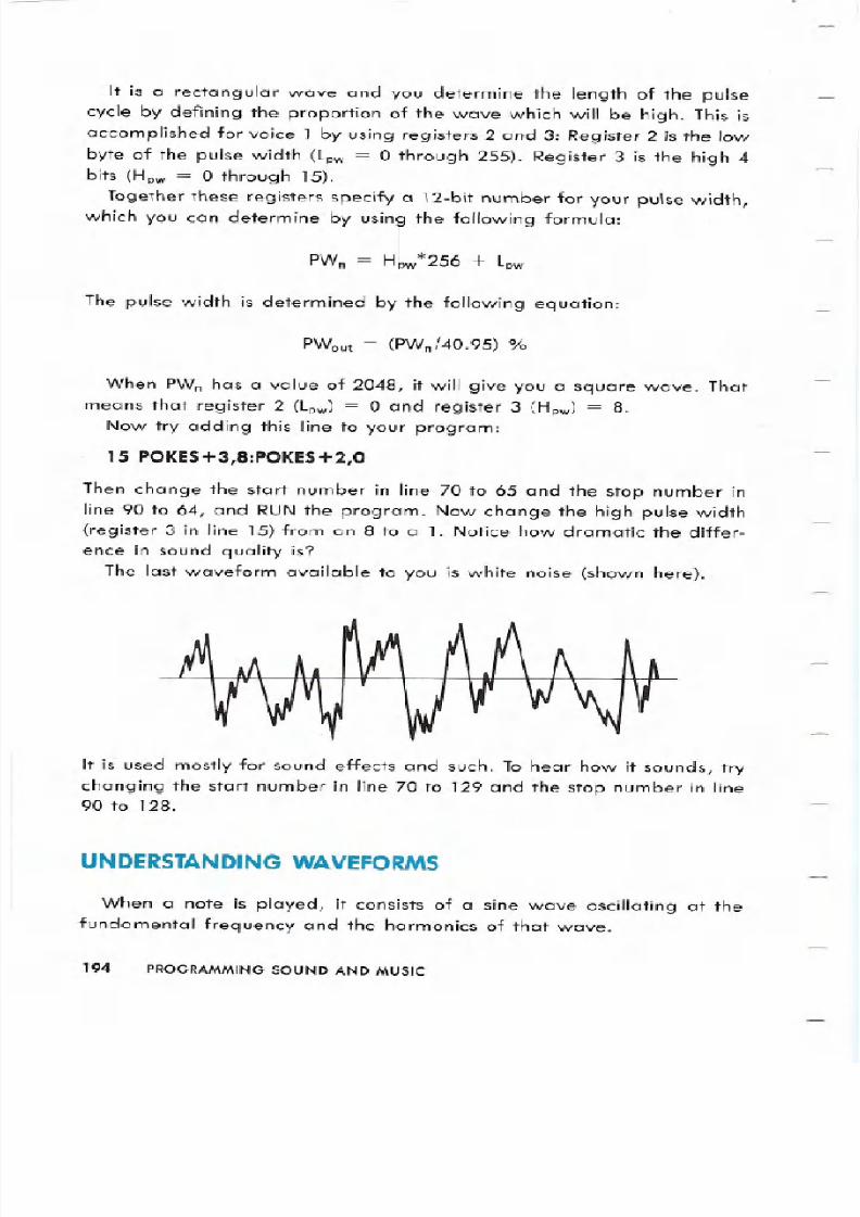
The last waveform available to you is white noise shown here).
It is used mostly for sound effects and such. To hear how it sounds, try
changing the start number in line 70 to 129 and the stop number in line90 to 128.
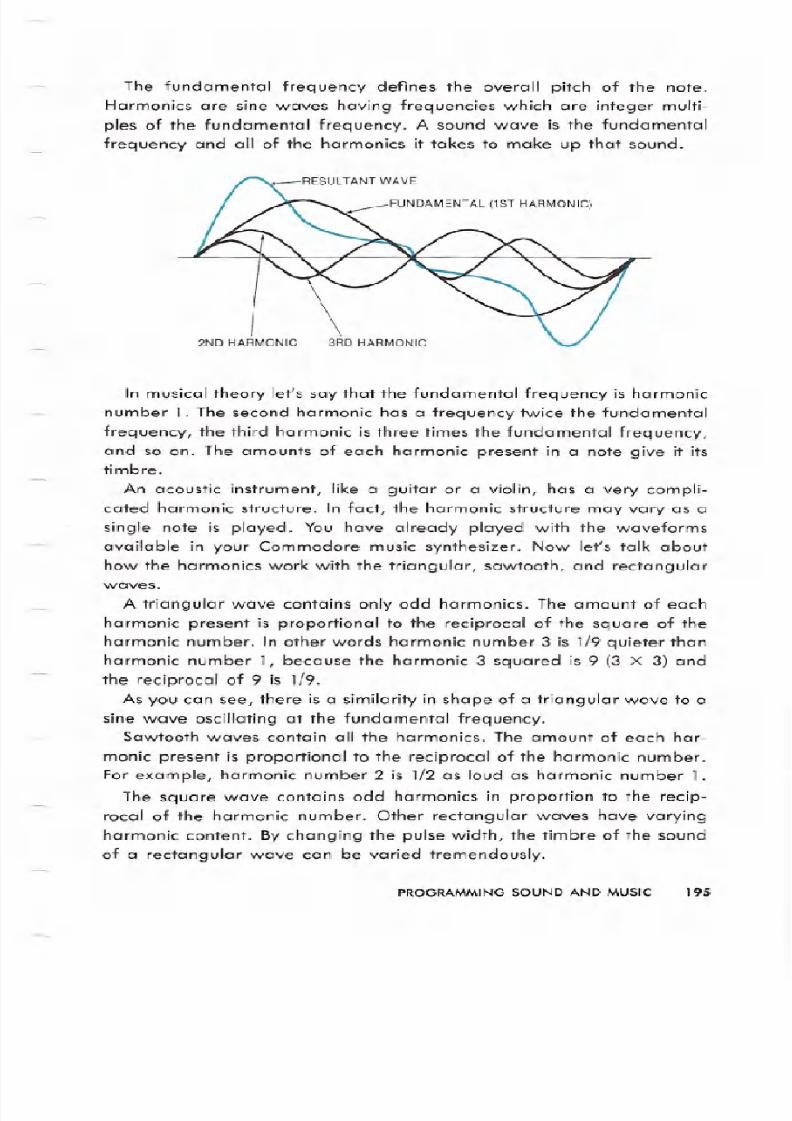
UN ERST N ING W VEFORMS
When a note is played, it consists of a sine wave oscillating at the
fundamental frequency and the harmonics of that wave.
9 PROGRAMMING SOUND AND MUSIC
8/12/2019 c64 Programmers Reference Guide 04 Programming Sound
http://slidepdf.com/reader/full/c64-programmers-reference-guide-04-programming-sound 13/26
8/12/2019 c64 Programmers Reference Guide 04 Programming Sound
http://slidepdf.com/reader/full/c64-programmers-reference-guide-04-programming-sound 14/26
By choosing carefully the waveform used you can start with a har-
monic structure that looks somewhat like the sound you want. To refine
the sound you can add another aspect of sound quality available on
your Commodore 64 called filtering which we ll discuss l ter in thissection.
THE ENVELOPE GENER TOR
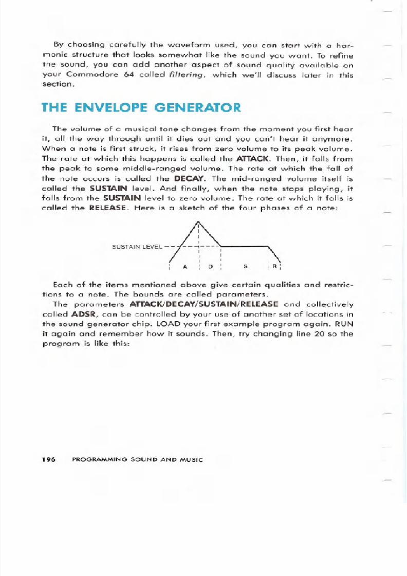
The volume of a musical tone changes from the moment you first hear
it all the way through until it dies out and you can t hear it anymore.
When a note is first struck it rises from zero volume to its peak volume.
The rate at which this happens is called the ATTACKThen it falls fromthe peak to some middle-ranged volume. The rate at which the fall of
the note occurs is called the DECAY The mid-ranged volume itself is
called the SUSTAIN level. And finally when the note stops playing itfalls from the SUSTAIN level to zero volume. The rate at which it falls is
called the RELEASEHere is a sketch of the four phases of a note:
SUSTAINLEVEL--
A
Each of the items mentioned above give certain qualities and restric-
tions to a note. The bounds are called parameters.
The parameters TT CKIDEC Y SUST IN RELE SEnd collectively
called ADSR can be controlled by your use of another set of locations in
the sound generator chip. LOADyour first example program again. RUNit again and remember how it sounds. Then try changing line 20 so the
program is like this:
196 PROGRAMMING SOUND AND MUSIC
8/12/2019 c64 Programmers Reference Guide 04 Programming Sound
http://slidepdf.com/reader/full/c64-programmers-reference-guide-04-programming-sound 15/26
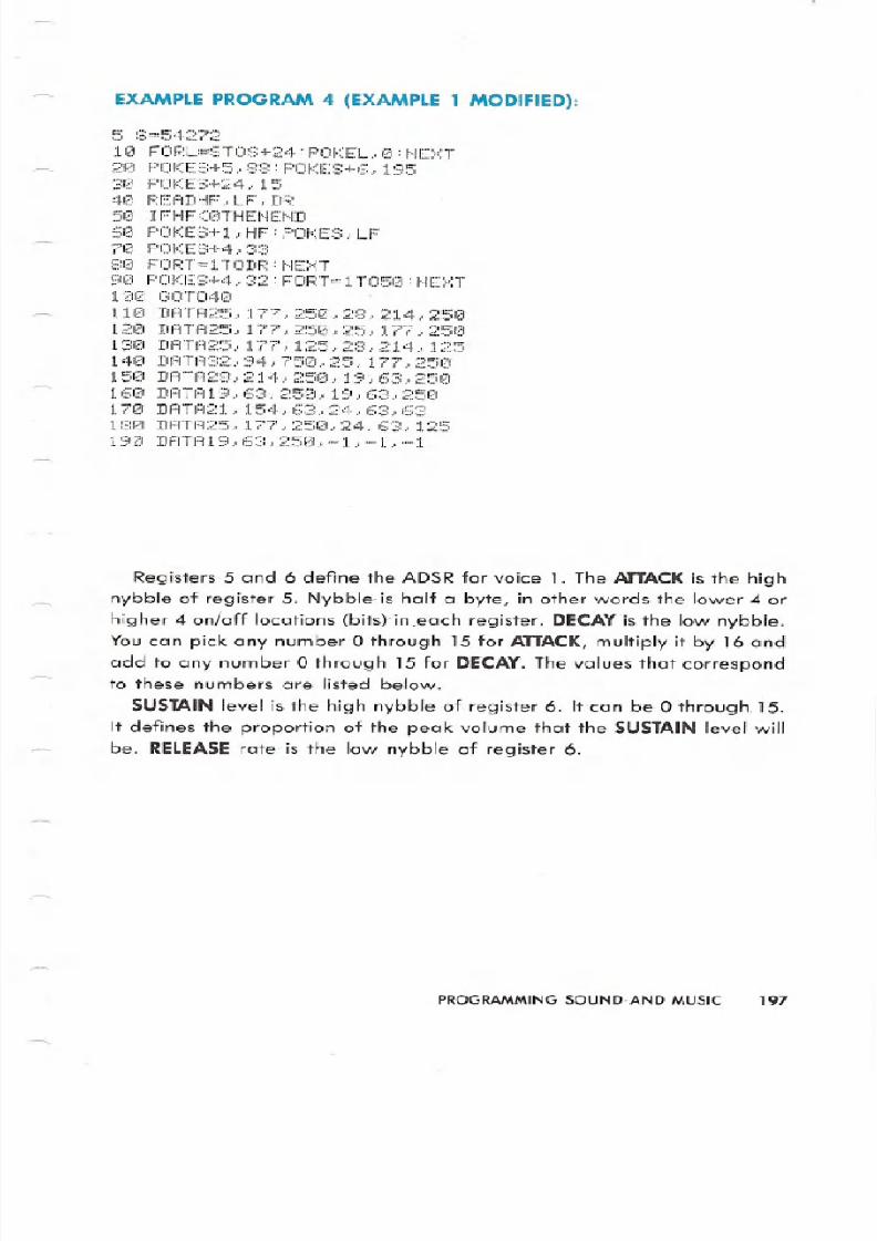
EXAMPLEPROGRAM 4 EXAMPLE 1 MODIFIED :
5 : =54 7
10 FORL~STOS 24:POKEL 0:NEXT
20 POKE:::;+5., :;:::::: F OKES+6, 1953121 PCW:ES+:;::4, 15
40 F :EADHF LF, DR50 IFHF<0THENEND60 POKES+l,HF:POKES,LF71<:1POKES+4 3380 FORT81TODR:NEXT
90 POKES+4,32:FORT=IT050:NEXT100 GOT040 .
110 DATA25,177,250,28,214,25012121DATli25, 177, 251::1 25., 177., 2512:1
130 DATA25,177,125,28,214, 125140 DATA32,94,750,25, 177,250150 DATA28,214,250,19~63,250160 DATAI9,63~250,19,63,250170 DATA21,154,63,24,63,63180 DATA25, 177,250,24,63,125190 DATAI9,63,250,-I,-I,-1
Registers 5 and 6 define the ADSRfor voice 1. The ATTACKs the highnybble of register 5. Nybble. is half a byte, in other words the lower 4 or
higher 4 on/off locations (bits) in .each register. DECAYis the low nybble.
You can pick any number 0 through 15 for ATTACKmultiply it by 16 and
add to any number 0 through 15 for DECAY The values that correspond
to these numbers are listed below.
SUSTAIN level is the high nybble of register 6. It can be 0 through, 15.
It defines the proportion of the peak volume that the SUSTAIN level will
be. RELEASE rate is the low nybble of register 6.
PROGRAMMINGOUND,ANDMUSIC 197
8/12/2019 c64 Programmers Reference Guide 04 Programming Sound
http://slidepdf.com/reader/full/c64-programmers-reference-guide-04-programming-sound 16/26
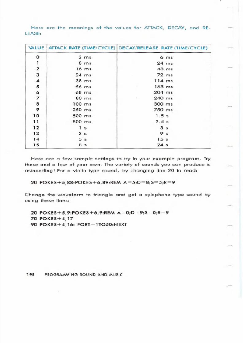
Here are the meanings of the values for ATTACK, DECAY, and RE-
LEASE:
Here are a few sample settings to try in your example program. Try
these and a few of your own. The variety of sounds you can produce is
astounding For a violin type sound, try changing line 2 to read:
20 POKES 5,88:POKES 6,89:REM A=5;D=8;S=5;R=9
Change the waveform to triangle and get a xylophone type sound by
using these lines:
20 POKES 5,9:POKES 6,9:REM A=0;D=9;S=0;R=9
70 POKES 4,17
90 POKES 4,16: FORT=1T050:NEXT
.198 PROGRAMMING SOUND AND MUSIC
VALUE ATTACK RATE TIME/CYCLE DECAY/RELEASE RATE TIME/CYCLE
2 ms 6 ms
1 8 ms 24 ms
2 16 ms 48 ms
3 24 ms 72 ms
4 38 ms 114 ms
5 56 ms 168 ms
6 68 ms 2 4 ms
7 8 ms 24 ms
8 1 ms 3 ms
9 25 ms 75 ms
1 5 ms 1 5 s
11 8 ms 2 4 s
12 1 s 3 s
13 3 s 9 s
14 5 s 15 s
15 8 s 24 s
8/12/2019 c64 Programmers Reference Guide 04 Programming Sound
http://slidepdf.com/reader/full/c64-programmers-reference-guide-04-programming-sound 17/26
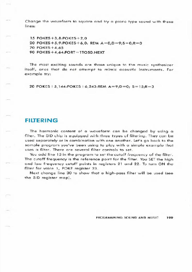
Change the waveform to square and try a ,piano type sound with theselines:
15 POKES+3,8:POKES+2,O
20 POKES+5,9:POKES+6,O: REMA=0;D=9;S=0;R=0
70 POKES+4,65
90 POKES+4,64:FORT=lT050:NEXT
The most exciting sounds are those unique to the music synthesizer
itself, ones that do not attempt to mimic acoustic instruments. For
example try:
20 POKES+5,144:POKES+6,243:REM A=9;D=0; S=15;R=3
ILT RING
The harmonic content of a waveform can be changed by using a
filter. The SID chip is equipped with thr types of filtering. They can be
used separately or in combination with one another. Let s go back to the
sample program you ve been using to play with a simple example thatuses a ,filter. There are several filter controls to set.
You add line 15 in the program to set the utoff fr qu n y of the filter.
The cutoff frequency is the reference point for the filter. You SETthe high
and low frequency cutoff points in registers 21 and 22. To turn ON the
filter for voice 1, POKE register 23.
Next change line 30 to show that a high-pass filter will be used see
the SID register map).
PROGRAMMING SOUND AND MUSIC 199
8/12/2019 c64 Programmers Reference Guide 04 Programming Sound
http://slidepdf.com/reader/full/c64-programmers-reference-guide-04-programming-sound 18/26
EXAMPLEPRO R M5 EXAMPLE1 MODIFIED :
10 FORL=STOS 24:POKEL 8:NEXT
15 POKES 22,128:POKES 21,0:POKES 23,120 POKES 5,9:POKES 6,03el POKES 24, 7940 READHF, LF . DF.:
50 IFHF<0THENEND
60 POKES l,HF;POKES,LF70 POKE::; 4, 33
80 FORT=ITODR:NEXT
98 POKES 4, 32: FORT= 1T050 : NE:-:T11210 00T04121
110 DATA25,177,250,28,214,250
120 DATA25, 177,250,25, 177,250131<:1DATA25.. 177.. 125,28..214.,12514121DATA32., 94, 7S12I,25, 177, 25121150 DATA28,214,250, 19,63,250160 DATA19,63,250,19,63,250
178 DATA21 , 154,63,24,63,63180 DATA25,177,250,24,63, 125
19121DATAI9,63,258,-1,-1,-1
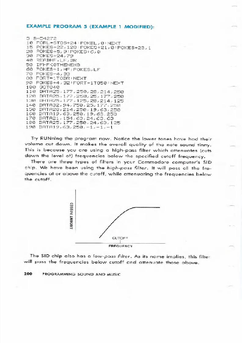
Try RUNning the program now. Notice the lower tones have had their
volume cut down. It makes the overall quality of the note sound tinny.
This is because you are using a high-pass filter which attenuates (cuts
down the level of) frequencies below the specified cutoff frequency.
There are three types of filters in your Commodore computer s SID
chip. We have been using the high pass filter It will pass all the fre-
quencies at or above the cutoff, while attenuating the frequencies belowthe cutoff.
QIIIII)II) Q...Z:;)o:;
FREQUENCY
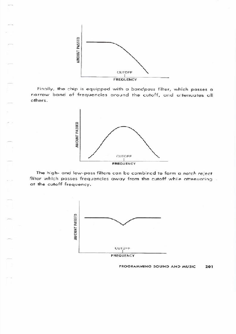
The SID chip also has a low pass filter As its name implies, this filter
will pass the frequencies below cutoff and attenuate those above.
200 PROGRAMMING SOUND AND MUSIC
8/12/2019 c64 Programmers Reference Guide 04 Programming Sound
http://slidepdf.com/reader/full/c64-programmers-reference-guide-04-programming-sound 19/26
QW
<I:II.I-Z:>o::;:<I:
Finally, the chip is equipped with a ndp ss filter, which passes a
narrow band of frequencies around the cutoff, and attenuates allothers.
QW
<I:II.I-Z
:>o::;:<I:
The high- and low-pass filters can be combined to form a notch reiect
filter which passes frequencies away from the cutoff while attenuating
at the cutoff frequency.
QIII
<I:II.I-Z
:>o::;:<I:
CUTOFF
FREQUENCY
PROGRAMMING SOUND AND MUSIC 2
8/12/2019 c64 Programmers Reference Guide 04 Programming Sound
http://slidepdf.com/reader/full/c64-programmers-reference-guide-04-programming-sound 20/26
Register 24 determines which type filter you want to use. This is in
addition to register 24 s function as the overall volume control. Bit 6
controls the high-pass filter 0 = off, 1 = on), bit 5 is the bandpass
filter, and bit 4 is the low-pass filter. The low 3 bits of the cutoff fre-
quency are determined by register 21 let let = 0 through 7). While the
8 bits of the high cutoff frequency are determined by register 22 Hct)
Hct = 0 through 255).
Through careful use of filtering, you can change the harmonic struc-
ture of any waveform to get just the sound you want. In addition, chang-
ing the filtering of a sound as it goes through the ADSR phases of its life
can produce interesting effects.
DV N ED TE HNIQUES
The SID chip s parameters can be changed dynamically during a note
or sound to create many interesting and fun effects. In order to make
this easy to do, digitized outputs from oscillator three and envelope
generator three are available for you in registers 27 and 28, respec-
tively.
The output of oscillator 3 register 27) is directly related to thewaveform selected. If you choose the sawtooth waveform of oscillator 3,
this register will present a series of numbers incremented increased
step by step) from 0 to 255 at a rate determined by the frequency of
oscillator 3. If you choose the triangle waveform, the output will incre-
ment from 0 up to 255, then decrement decrease step by step) back
down to o. If you choose the pulse wave, the output will jump back-
and-forth between 0 and 255. Finally, choosing the noise waveform will
give you a series of random numbers. When oscillator 3 is used formodulation, you usually do NOT want to hear its output. Setting bit 7 of
register 24 turns the audio output of voice 3 off. Register 27 always
reflects the changing output of the oscillator and is not affected in any
way by the envelope ADSR) generator.
202 PROGRAMMING SOUND AND MUSIC
8/12/2019 c64 Programmers Reference Guide 04 Programming Sound
http://slidepdf.com/reader/full/c64-programmers-reference-guide-04-programming-sound 21/26
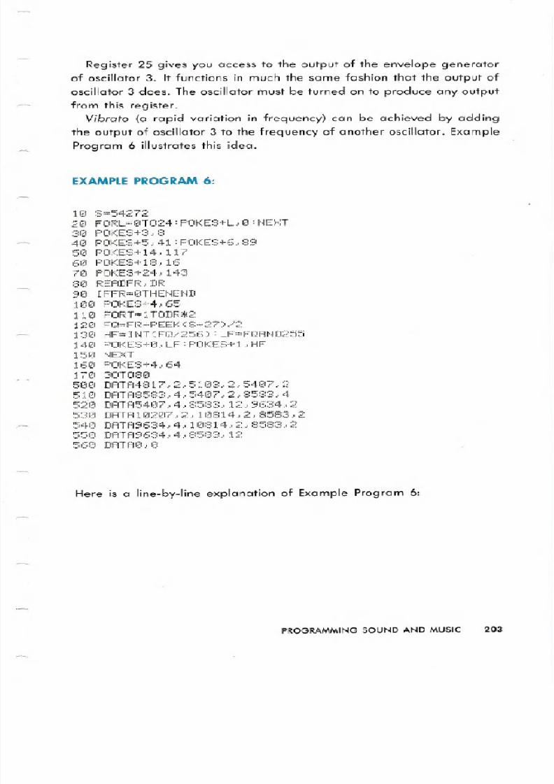
Register 25 gives you access to the output of the envelope generator
of oscillator 3. It functions in much the same fashion that the output of
oscillator 3 does. The oscillator must be turned on to produce any output
from this register. ibr to a rapid variation in frequency can be achieved by adding
the output of oscillator 3 to the frequency of another oscillator. Example
Program 6 illustrates this idea.
EXAMPLE PROGRAM 6:
8=54 7
20 FORL=0T024:POKES+L,0:NEXT31Z1 F CiKES+3, 8
40 POKES+5,41:POKES+6,8950 F OKES+14..117
60 POKE::::+18., 16
70 POKE:;:;+24., 143
:3121 READFf<:, DR
90 IFFR=0THENEND100 POKES+4,65
110 FORT=lTODR*2
12121 FQ=FR+PEEK 0:8+27 >/2130 HF=INT(FQ/256>:LF=FQAND255140 F OKES+0,LF:POKES+l,HF150 NE::<:T
160 POKES+4., 64
170 GOT080500 DATA4817,2,5103,2,5407,2510 DATA8583,4,5407,Z,8583,4520 DATA5407,4,8583,12,9634,2530 DATAI0207,2,10814,2,8583,2540 DATA9634,4,10814,2,8583,2
550 DATA9634,4,8583,1256121 DATI 10., I
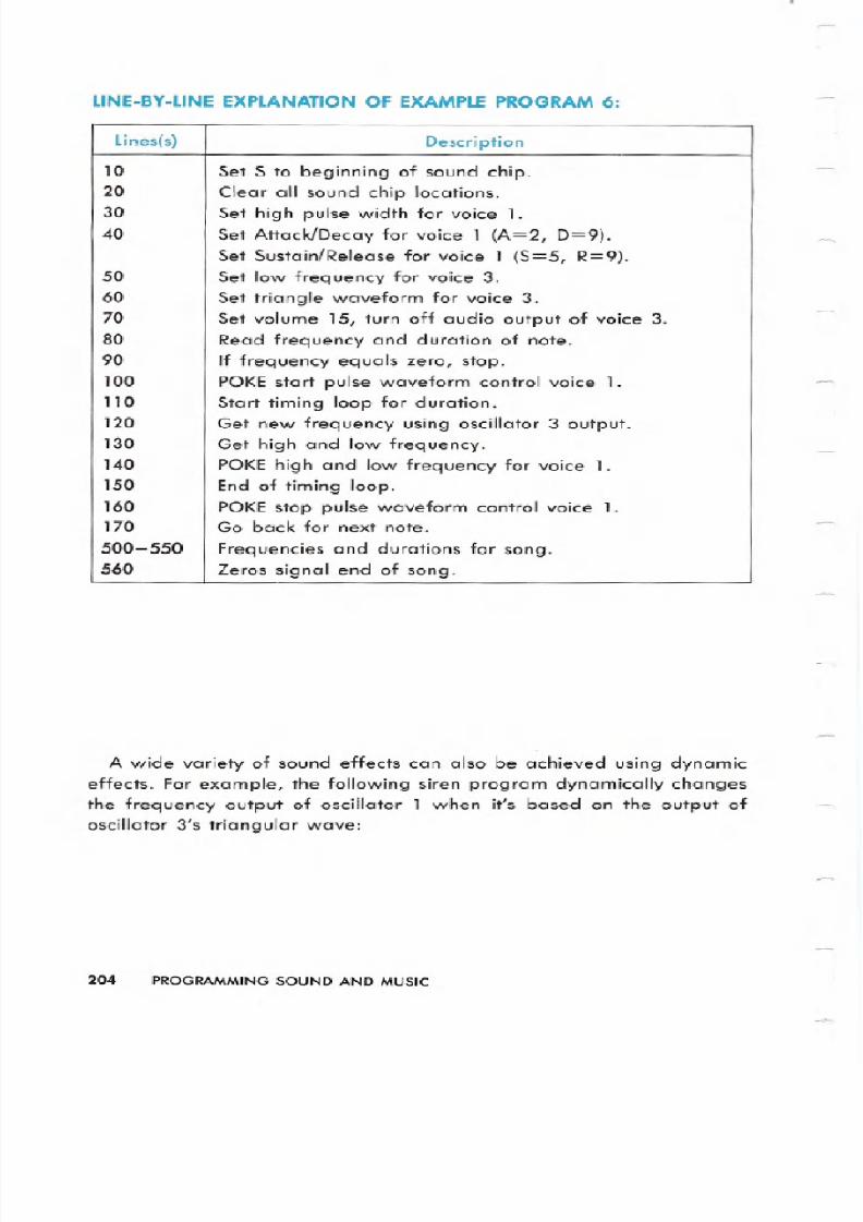
Here is a line-by-line explanation of Example Program 6:
PROGRAMMINGOUNDAND MUSIC 3
8/12/2019 c64 Programmers Reference Guide 04 Programming Sound
http://slidepdf.com/reader/full/c64-programmers-reference-guide-04-programming-sound 22/26
LlNE BY LiNEEXPL N TIONOF EX MPLEPROGR M
A wide variety of sound effects can also be achieved using dynamic
effects. For example, the following siren program dynamically changes
the frequency output of oscillator 1 when it s based on the output of
oscillator 3 s triangular wave:
204 PROGRAMMING SOUND ND MUSI
LinesCs) Description
10 Set S to beginning of sound chip.20 Clear all sound chip locations.30 Set high pulse width for voice 1.40 Set Attack/Decay for voice 1 A=2, D=9).
Set Sustain/Release for voice 1 S=5, R=9).50 Set low frequency for voice 3.60 Set triangle waveform for voice 3.70 Set volume 15, turn off audio output of voice 3.
80 Read frequency and duration of note.90 If frequency equals zero, stop.100 PO start pulse waveform control voice 1.110 Start timing loop for duration.120 Get new frequency using oscillator 3 output.130 Get high and low frequency.140 POKE high and low frequency for voice 1.150 End of timing loop.160
POKE stop pulse waveform control voice 1.170 Go back for next note.
500-550 Frequencies and durations for song.560 Zeros signal end of song.

8/12/2019 c64 Programmers Reference Guide 04 Programming Sound
http://slidepdf.com/reader/full/c64-programmers-reference-guide-04-programming-sound 23/26
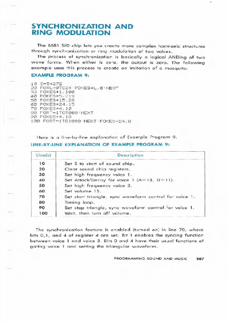
EXAMPLE PROGRAM
10 8=54272
20 FORL=0T024=POKES+L,O=NEXT
30 POKES+14,540 POKES+18,1650 POKES+3,160 POKES+24,14370-POKES+6,24080 POKES+4,6590 FR=5389100110120130
140150
FORT=lT0200FQ=FR+PEEK S+27 .3.5HF=INT FQ/256 =LF=FQ-HFI256POKES+0,LF=POKES+l,HF
NEKTPOKES+24,0
Here is a line-by-line explanation of Example Program 7:
LlNE BY LiNEEXPL N TIONOF EX MPLEPROGR M
PROGRAMMING SOUND ND MUSI 5
Line s Description
10 Set S to start of sound chip.
20 Clear sound chip registers.
30 Set low frequency of voice 3.40 Set triangular waveform voice 3.50 Set high pulse width for voice 1.60 Set volume 15, turn off audio output of voice 3.70 Set Sustain/Release for voice 1 S= 15, R=O .
80 POKE start pulse waveform control voice 1.
90 Set lowest -frequency for siren.
100 Begin timing loop.110 Get new frequency using output of oscillator 3.120 Get high and low frequencies.130 POKE high and low frequencies for voice 1.140 End timing loop.150 Turn off volume.
8/12/2019 c64 Programmers Reference Guide 04 Programming Sound
http://slidepdf.com/reader/full/c64-programmers-reference-guide-04-programming-sound 24/26
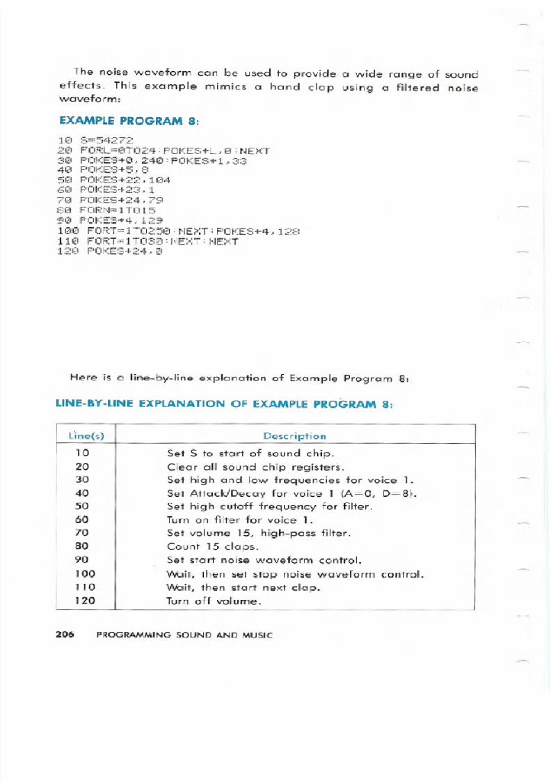
The noise waveform can be used to provide a wide range of sound
effects. This example mimics a hand clap using a filtered noisewaveform:
EX MPLE PROGR M
110 8=54272
210 FORL=eT024:POKES L,e:NEXT
310 POKES 0,24iZ1:POKES 1,33
410 POKE8 5,8
510 POI ES+22., 11214
610 POf ES 23, 1
710 POKES 24,79
810 FORN=1T015
90 POKES 4,129
1010 FORT=1T0250:NEXT:POKES 4,128
1110 FORT= 1T030 :t.jE:.:Tt~E>::T
12121 POKES 24,1O
Here is a line-by-line explanation of Example Program 8:
LlNE BY LiNEEXPL N TIONOF EX MPLEPROGR M
206 PROGRAMMING SOUND ND MUSI
Line s Description
10 Set S to start of sound chip.20 Clear all sound chip registers.30 Set high and low frequencies for voice 1.40 Set Attack/Decay for voice 1 A=O, D=8 .50 Set high cutoff frequency for filter.60 Turn on filter for voice 1.
70 Set volume 15, high-pass filter.80 Count 15 claps.
90 Set start noise waveform control.100 Wait, then set stop noise waveform control.110 Wait, then start next clap.120 Turn off volume.
8/12/2019 c64 Programmers Reference Guide 04 Programming Sound
http://slidepdf.com/reader/full/c64-programmers-reference-guide-04-programming-sound 25/26
8/12/2019 c64 Programmers Reference Guide 04 Programming Sound
http://slidepdf.com/reader/full/c64-programmers-reference-guide-04-programming-sound 26/26
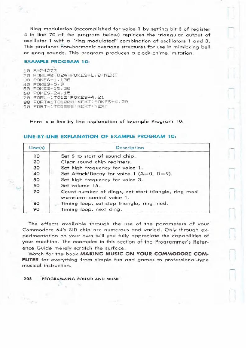
Ring modulation (accomplished for voice 1 by setting bit 3 of register
4 in line 70 of the program below) replaces the triangular output of
oscillator 1 with a ring modulated combination of oscillators 1 and 3.
This produces non-harmonic overtone structures for use in mimicking bellor gong sounds. This program produces a clock chime imitation:
EXAMPLE PROGRAM 1 :
1121 8=5 7
20 FORL=0T024:POKES+L,0:NEXT30 POKES l,130
40 POKES 5,9
50.POKES 15,3060 POKES 24,15
70 FORL=lT012:POKES 4,2180 FORT=lT01000:NEXT:POKES 4,20
90 FORT=lT01000:NEXT:NEXT
Here is a line-by-line explanation of Example Program 10:
LlNE BY LiNE EXPLANATION OF EXAMPLE PROGRAM 1 :
The effects available through the use of the parameters of your
Commodore 64 s SID chip are numerous and varied. Only through ex-
perimentation on your own will you fully appreciate the capabilities of
your machine. The examples in this section of the Programmer s Refer-
ence Guide merely scratch the surface.Watch for the book MAKING MUSIC ON YOUR COMMODORECOM
PUTERfor everything from simple fun and games to professional-typemusical instruction.
2 8 PROGRAMMING SOUND AND MUSIC
Line(s) Description
10 Set S to start of sound chip.20 Clear sound chip registers.30 Set high frequency for voice 1.40 Set Attack/Decay for voice 1 (A=O, D=9).50 Set high frequency for voice 3.60 Set volume 15.
70 Count number of dings, set start triangle, ring mod
waveform control voice 1.80 Timing loop, set stop triangle, ring mod.
90 Timing loop, next ding.