Embed Size (px)
Citation preview
AD-A161 805
TECHNICAL REPORT ARLC8 TR 85035
PREDICTING CATASTROPHIC OUTSIDE DIAMETERINITIATED FATIGUE FAILURE OF THICK-WALLED
:i CYLINDERS USING LOW CYCLE FATIGUE DATA
JOSEPH A. KAPP
DTICQ/ELECTE
SEPTEMBER 1985
US ARMY ARMAMENT RESEARCH AN 0 DEVELOPMENT CENTERLARGE CALIBER WEAPON SYSTEMS LABORATORY
BENET WEAPONS LABORATORYWATERVLIET N.Y. -12189
APPROVED FOR PUBLIC RELEASE; DISTRIBUTION UNLIMITED
C3,jU
Reproduced FromBest Available Copy

The findings in this -report are not to be con truee S an official
Department of the Army position unless so designated by other authorized
p documents.
The use of trade name(s) and/or manufacture(s) does not constitute
an official Indorsement or approval.
DZSMOITION
Destroy this report when it is no 1,nger needed., Do not return it
to the originator.'

SECURITY CLASSIFICATION 00 THIS PAGE (hen Deta Eotedr
READ INSTRUCTIONSREPORT DOCUMENTA1 ION PAGE BEFORE COMPLETTNG FORM. EPORT NUMBER 2. GO4T ACCESSION' NO. 3, R CIPIENT'S CATALOG NUMBER
4. TITLE (and Subtitie) S. TYPe OPP REPORT A PERIOD COVERED
PREDICTING CATASTROPHIC OUTSIDE DIAMETER
INITIA.TED FATIGUE FAILURE OF THICK-WALLEDCYLINDERS USING LOW CYCLE FATIGUE DATA 6. PERFORMING ORG. REPORT NUMBER
7. AUTHOx(o) 4. CONTRACT OR GRANT NUMBER(e)
Joseph A. Kapp
9. PERFORMING ORGANIZATIO## NAME AND AORESS t0. PROGRAM ELEMENT. PROJECT, TASKAREA & WORK UNIT NUMBERS
US Army Armament Research & Development Center S NO.6111.O2.H600.011Benet Weapons Laboratory, SMCAR-LCB-TL PRON NO. 1A325B54IA1AWatervilet, NY 12189-5000 PRON NO. IA_2_B_41AIA11. CONTROLLING OFFICE NAME AND ADDRESS 12. REPORT OATE
US Army Armament Research & Development Center September 1985Large Caliber Weapon Systems Laboratory I. NUMBER OF PAGES
Dover. NJ 07801-5001 13I& MONITORING AGE1NCY NAM
IE & AODRESS(II diderew rom Contoltln 0 ffice) 1S. SECURITY CLASS. (of thie report)
Unclassi fiedIS*. DECLASSIFICATION/DOWNGRADING
SCHEDULE
14. DISTRIBUTION STATEMENT (of thle Report)
Approved for public release; Distribution unlimited
17. DISTRIBUTION STATEMENT (of the abstracet entered In Black 20. it dlifferant hoe. Report)
IS. SUPPLEMENTARY NOTXS
Presented at the IX Airapt High Pres;ure Conference, 25-28 July 1983
I. KIEY WORDS (Continve on r ree eide It Meceeesry end Idevntlf by block number)
Thick-Walled Cylinders Residual Stress EffectsFatigue Predictive MethodsAutofrettage Pressure Vessels
20. ANSTR AC.1 (Cof..u ou roera stall Nf me.wwww ed Ide.I fy by block rnmabe.)
A procedure is presented to predict fatigue failure of thick-walled cylinderscontaining discontinuities at the outside diameter (OD). Both crack initiationlife and crack growth are considered. The elastic-plastic strains at an ODdiscontinuity are estimated using elastic analysis and stress concentrationfactors. The strain estimates are then used in conjunction with low cyclefatigue data to del:ermine the initiation life. Crack growth life is estimated
(CONT'D ON REVERSE)
DO I'7 103 EDTo.o,.OVsISOLETE UNCLASSIFIED
SECUIST" CLASSM FICATrof OF TIS PAGE (When Dat. Etererd

SCCUPITY CLASSIFICATION Of THIS PAOZ(W .Dat. Zaemd)
* 20. ABSTRACT (C0NT'D)
by integration of a power law relationship. The results obtained by using* this-analysis method compared to meaqured fatigue life data for several OD* initiated failures in thick-walled cylinders agrees to within about-ten* percent.
SIECUNITY CLASSIPICATION OF THIS PAGIE("ein Doa Enterad)

TABLE OF CONTENTS
ACKNOWLEDGEMENTS
INTRODUCTION I
PROCEDURE .1
RESULTS AND DISCUSSION 5
REFERENCES 8
* TABLES
I. RESULTS FOR THICK-WALLED C LINDER WITH TYPE B EXTERNAL 6NOTCHES
I!. RESULTS FOR THICK-WALLED CYLINDER WITH TYPE B EXTERNAL 6NOTCHES
III. RESULTS FOR VICK-WALLED CYLINDER WITH TYPE A EXTERNAL 7NOTCH
LIST OF ILLUSTRATIONS
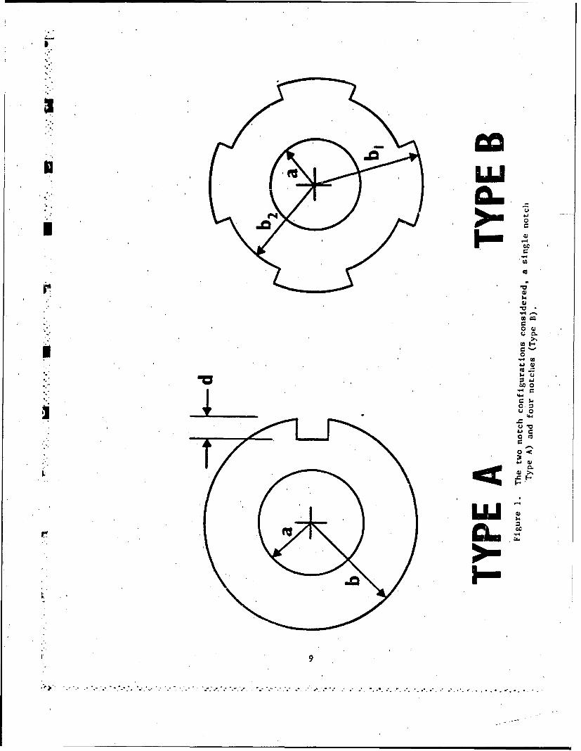
1. The two notch configurations considered, a single notch 9(Type A) and four notches (Type B).
2. Low cycle fatigue data for the steel used to manufacture 10the cylinders studied.
3. Comparison of stabilized cyclic stress-strain curves for 11Ace - 0.5 percent.
IN.- .'
p Z
I. . .& ; ,\ . . . .

'ACKNOWLEDGEMENTS
The author wishes to thank Mr. B. Brown for much of the fatigue life
data reported herein, Mr. R. Abbott for performing the low cycle fatigue
tests, and E. Fogarty for preparing the manuscript.
U o
U
o~i"
I

INTRODUCTION
LThick-walled iylinders are often autofrettaged to enhance their fatigue.K- lives (ref 1). The greater fatigue life results because of the compressive
residual stresses at the inner diameter (ID). If the cylinder also contains a
discontinuity at the outside diameter (OD) where the residual stresses are
tensile, the combination of stress concentration and tensile operating and
residual stresses often results in shortened fatigue life due to crack
initiation at the OD.
Several attempts have been made to model this behavior experimentally
(refs 2-4) and analytically (ref 5). This report presents a two-step
prediction method which results in very'accurate estimates of total fatigue
life. The first step is to determine the crack initiation life through the
use of low cycle fatigue data. A small semi-circular crack is then assumed to
exist. Using known stress intensity factor solutions corrected for curvature,Ucrack propagation life is predicted by integrating a power law relatipnship
that accounts for mean stress effects (ref 6). The'total fatigue life is then
the sum of the initiation life and the propagation life. Fatigue lives
predicted by this method agree very well with the measured lives of several
thick-walled cylinders that fail from the OD.
*I PROCEDURE
Two different OD notch configurations shown in Figure I were studied, a
single notch, Type A, and four notches, Type B. We assume that the material
* at the roots of these notches responds to service loading in the same manner
References are listed at the end of this report.
o-
U1
S5

N
as a smooth cylindrical low cycle fatigue sample. By estimating the strain
range that the material at the notch tip is subjected to, we should be able to
determine the number of cycles to initiate a crack. This is accomplished with
the assistance of the strain range versus cycles-to-failure plot shown in
Figure 2. The plot was developed using smooth cylindrical specimens of the
same steel used to manufacture the pressure vessels studied.
The three curves in Figure Z are for three different strain ratios (R
Emin/lmax). This was included because the presence of autofrettage residual
stresses will change R for the same internal pressure cycle. The three
conditions tested were R = 0, no autofrettage; R - 0.5, high tensile residual
stress; and R - 0.25, in between. The results show that the longest life was
obtained with R - 0, the shortest with R - 0.25, and for R - 0.5, cycles-to-
failure fell between these two maximina, although at large values of st:ain
range there was no difference in the cycles-to-failure. The reason for
these differences is explained by the stabilized cyclic strain curves that
developed. When Ac was large there was essentially no difference in the
hysteresis loops developed, thus no'measurable difference in life, whereas the
-.. cyclic stress-strain behavior eeveloped at smaller strain ranges was
different. Often under these conditions, the cyclic stress-strain curves were
* simply elastic loadings and unloadings.
Figure 3 shows the actual results for Ac 0.5 percent. The cumulative
damage that results in failure of the specimen is a combination of two
- factors, the initial damage from 'the first loading to maximum strain and the
cyclic loading. We would expect that the larger the initial strain the
shorter the life, and the greatew the amount of'compression during cyclic
2
U:.-

.6
-' loading the shorter the life. Because of the strain hardening of the steel,
the R = 0 sample saw the most compression and the least initial strain,
conversely, R - 0.5 had the least compression and the most initial strain,
while the R - 0.25 saw intermediate values of each. The results of these
tests suggest that the combination of two factors contributing to life is
synergistic with the R - 0.25, the in between case being the worst.
Relating these low cycle fatigue results to OD failure was accomplished
in the following manner. Two parameters had to be determined: strain range'
A- and R. By using an elastic analysis these two values can be estimated.
The minimum stress 'in an autofrettaged cylinder is ktoA, where kt is the
* stress concentration factor and aA is the elastic residual stress. Similarly,
the maximum stress would be the minimum stress plus kt o, where ap is theit p
stress due to pressure. The strain applied to the material at the notch tip
then are estimated asOmin ktoA
.min ...---- ----- (1)E E
~kt yp
emax + ---- (2)~E
where E is Young's modulus for the material.
Using Eqs. (i) and (2) both the Ac and R parameters are easily
calculated; AC - emax -emin, and R - cmin/cmax. For the cylinders considered
below, this technique was used and kt was either determined by finite element
V results available in the literature or by a Neubers Diagram (ref 7), and E was6 207 GPa. Once AC and R were calculated, the number of cycles to crack
initiation was determined by interpolation of three curves in Figure 2.
Otis
3',
-r

.%
Although crack initiation may consume a significant portion of the useful
fatigue life of an OD notched thick-walled cylinder, the contribution of crack
propagation must also be considered. To model crack growth, the following
assumptions were made. At crack initiation a small semi-circular crack was
produced. This crack was assumed to act as a crack with a depth equal to the
notch depth and was semi-circular. The stress intensity factor for the crack
was assumed to be the stress intensity factor for a straight-fronted crack of
the same depth divided by the complete elliptical integral of the second kind
to account for the curvature.
K(straight crack),K(curved crack) (
The K solution for an OD cracked pressurized cylinder and for an OD
cracked cylinder with autofrettage residual stress have been developed
elsewhere (ref 5). The value of 4 used was that for'a semi-circular crack
which is 1.5708. Propagation of such a crack was assumed to follow a
constitutive law given as (ref 6):
dc n- A max (4)
dN(4
where dc/dN is the crack growth rate, Kmax is the maximum occurring stress
_. intensity factor during a fatigue cycle, and A and n are material properties.
Using Eq. (4).accounts' for the mean K effect on crack propagation and has been
shown to be the most conservative growth law for crack growth In OD cracked
autofrettaged cylinders (ref 5). The crack growth life was determined by
integration of Eq. (4).
4
• o.

RESULTS AND DISCUSSION
The results obtained from the analysis of several thick-walled cylinders
are summarized in Tables I, II, and III. Table I is for a relatively small
cylinder u;.th Type B (Figure 1) OD notches. Fracture toughness values are
given since they detetmine the critical crack size and thus influence the
crack propagation life. The comparison of the eetimated life and the actual
life shows excellent agreement with many of the actual samples. The last two
specimens had much longer' lives than estimated. This may be the result of
•assuming the worst case. The actual value of the root' radius was not measured
for each cylinder. The minimum radius of 0.254 mm was assumed. Actual values
for this dimension could be in the range from 0.254 mm to 0.508 mm. If we
analyze this cylinder with a root radius of 0.508 mm, the stress concentration
factor kt is reduced from 3.0 to about 2.5. Such a reduction in kt would
increase the initiation life from 3400 cycles to 5700 cycles. Using this for
initiation life increases the predicted lives of specimens 844-1R-B and 7344P, to 6245 cycles and 6233 cycles, respectively, which are in much better
agreement with the actual fatigue lives.
Another series of tests of the Type B configuration is pre.scnted in Table
II. The agreement for these somewhat larger cylinders is not quite as good as
with the small cylinders in Table I. In all cases, fatigue life is under-
estimated by about 5000 cycles or about 30 percent. The same argument
presented above can be applied here, namely the actual value of the root
radius was not measured and could vary between 0.254 mm and 0.508,mm. Using
the maximum value, kt is reduced to about 2.9 from 3.2 increasing the
5I.

TABLE I. RESULTS FOR THICK-WALLE CYLINDER WITH TYPE B EXTERNAL NOTCHES,a - 6.56 cq, bl - 10.68 cui, b2 - 11. cm, Pressure'- 496 MPa,Yield Strength 1240 M.a, Root Radius = 0.254 mm, kt - 3.0, 100Percent Overstrain.
I I K 1I I Estimated I Actual II Specimen i (MPam) I Life (Cycles) I Life (Cycles) II _ _ _ _ _ _ _ I _ _ _ _ _ I I
i 917-3R-T 14/ i 4151 4310 iI I I917-4R-T 152 I 4220 4917I I I I
I 7404 130 3910 3267 I
;7414 123 3817 3948 I
I 844-IR-B 133 3945 6302 IVr i i. 7344 132 3933 '5607 I
TABLE II. RESULTS FOR THICK-WALLED CYLINDER WITH TYPE B EXTERNAL NOTCHES,a - 8.26 cm, bi 14.56 cm, b2 15.08 cm, Pressure - 372 MPa,Yield Strength :1170 MPa, Root Radius 0.254 mm, kt :3.2, 100Percent Overstrain.
-' -iI 1 'i *I
I .. K I Estimated I Actual II Specimen I (MPatm) i Life (Cycles) I Life (Cycles) II _ _ _ _ I I_ _ _ _ _ I _ _ _ _ _ I
41 180 15536 24797
I 51 164 15133 18006
52 139 14289 19504
I 54 135 14156 19993
" I 44 165 15193 20991ar
I-45 146 14637 19862
6
I. ,=

-I
initiation life from 12,000 cycles to 15,000 cycles. This reduces the under-
Sestimate of actual life to about 2000 cycles or about ten percent.
The response of several Type A cylinders is summarized in Table III.
. This kind of notch is more severe than Type B notches as can be seen in the
value of kt . Again, the analysis method yields excellent agreement with
actual behavior. The estimated life for three of the four conditions
* [ considered is within about 10 percent of the actual behavior. But te
technique drastically underestimates the least severe case (smallest kt and
least: percent overstrain). The reason for the discrepancy is not clear,
suggesting that the method of analysis may be limited to only that cL ., of
cylinders that would fail at relatively short life.
TABLE III. RESULTS FOR THICK-WALLED CYLINDER WITH TYPE A EXTERNAL NOTCH,a - 7.75 cm, b - 13.5 cm, Root Radius - 0.'762 mm, KIc- 127MPa/m, Yield Strength -,1170 MPa, Pressure - 386 MPa.
I I i I I Etm ed I il [ Notch Estimated [Actual
I I Depth I' I Percent Life, I Life II Specimen I (mm) I kt I Overstrain I (Cycles) I (Cycles) I
%"..II i 1T 1 f I
D2 10.2 6.0 100 I 2887 3003I II IIII
I D3 10.2 6.0 i100 I 2887 2452
D4 10.2 6.0 60 4255 4079
B D5 10.2 5.0 .60 4255 4252
S1 5.1 3.6 100 10776' 9280
I"S2 5.1 3.6 I100 10776 11224
S $3 5.1, 3.6 60 15862 42985
"S4 1 5.1 3.6 60 15862 40266
7
- , , ,,. * . *, * *

P,
REFERENCES
1. T. E. Davidson and D. P. Kendall, The Mechanical Behavior of Materials
Upder Pressure, (H.L.I.D. Pugh, ed.), Elsevier Publishing, Amsterdam,
1970.
2. J. A. Kapp and J. H. Underwood, Experimental Mechanics, Vol. 22, No. 3,
March 1982,'pp. 96-100.
,3. Robert R. Fujczak, "Effects of a R-Ratio Crack Initiation at External
Discontinuities in Autofr.ttaged Cylinders," Experimental Mechanics, Vol.
24, No. 2, June 1984, pp. 122-128.
4. J. H,. Underwood, "Fatigue Life Analysis and Tensile Overload Effects
With High Strength Steel Notched Specimeas," ARDC Technical Report ARLCB-
TR-83040, Benet Weapons Laboratory, Watervliet, NY, November 1983.
5. J. A. Kapp and S. L. Pu, "Fatigue Design of Thick-Walled Cylinders
Considering the OD as a Failure Initiation Site," Pressure Vessel Design
PVP-57, (G. E. 0. Widem, ed.), American Society for Mechanical Engineers,
New York, 1982.
6. K. Tabeshfar and T. R. G. Williams, Journal of Sound-and Vibration, Vol.
68, No. 2, 1980, p. 25.
7. A. C. Vigural and S. K. Feuster, Advanced Strength and Applied Elasticity,
Elasticity, American Elsevier Publishing Company, New York, 1975 p. 83.
8
*. - .-. - .-
LU0~~
UI
'-4
0
1~-V-4-'
owc.; ~.
01-.
0
4J4j
"4
CI.'
'4.4
U V
C
3JJG)
___ 0~-
L
9

'U 4V4-
C
c
6 02
3ONVUn- N 'IR
10.

--
0 -nzs a
oD 0,0~'-44
SS3HIS_

TECHNICAL REPORT INTERNAL DISTRIBUTION LIST
4O. OFCOPIES
CHIEF, DEVELOPMENT ENGINEERING BRANCHATTN: SMCAR-LCB-D 1
-DA 1-DP 1-PR 1-DS (SYSTEMS) ]-DS (ICAS GROUP) 1-DC I-DM 1
CHIEF, ENGINEERING SUPPORT BRANCHATTN: SMCAR-LCB-S 1,
-SE 1
CHIEF, RESEARCH BRANCHATTN: SMCAR-LCB-R 2
-R (ELLEN FOGARTY) 1-RA 1-RM 2-RP 1-RT i
TECHNICAL LIBRARY 5ATTN: SMCAR-LCB-TL
TECHNICAL PUBLICATIONS & EDITING UNIT 2ATTN: SMCAR-LCB-TL
DIRECTOR, OPERATIONS DIRECTORATE I
DIRECTOR, PROCUREMENT DIRECTORATE 1
DIRECTOR, PRODUCT ASSURANCE DIRECTORATE 1
NOTE: PLEASE NOTIFY DIRECTOR, BENET WEAPONS LABORATORY, ATTN: SMCAR-LCB-TL,
OF ANY ADDRESS CHANGES.

TECHNICAL REPORT EXTERNAL DISTRIBUTION LIST
NO. OF NO. OFCOPIES COPIES
ASST SEC OF THE ARMY COMMANDERRESEARCH & DEVELOPMENT US ARMY AMCCOM
ATTN: DEP FOR SCI & TECH 1 ATTN: SMCAR-ESP-L
THE PENTAGON ROCK ISLAND, IL 61299
WASHINGTON, D.C. 20315COMMANDER
COMMANDER ROCK ISLAND ARSENAL
DEFENSE TECHtICAL INFO CENTER 12 ATTN: SMCRI-ENM (MAT SCI 'DIV)ATTN: DTIC-DDA ROCK ISLAND, IL 61299
CAMERON STATIONALEXANDRIA, VA 22314 DIRECTOR
US ARMY INDUSTRIAL BASE ENG ACTVCOMMANDER ATTN: DRXIB-MUS ARMY MAT DEV & READ COMD ROCK ISLAND, IL 61299ATITN: DRCDE-SG 1
5001 EISENHOWER AVE COMMANDERALEXANDRIA, VA 22333 US AP-MY TANK-AUTMV R&D COMD
ATTN: TECH LIB - DRSTA-TSLCOMMANDER WARREN, MI 48090ARMAMENT RES & DEV CTRUS ARMY AMCCOM COMMANDERATTN: SMCAR-LC 1 US ARMY TANK-AUTMV CORD
SMCAR-LCE I ATTN: DRSTA-RCSMCAR-LCM (BLDG 321) 1 WARREN, MI 48090
SMCAR-LCS 1SMCAR-LCU 1 COMMANDERSMCAR-LCW 1 US MILITARY ACADEMYSMCAR-SCM-O (PLASTICS TECH 1 ATTN: CHMN, MECH ENGR DEPT
EVAL CTR, WEST POINT, NY 10996BLDG. 351N)
SMCAR-TSS (STINFO) 2 US ARMY MISSILE COMDDOVER, NJ 0780.1 REDSTONE SCIENTIFIC INFO CTR 2
ATTN: DOCUMENTS SECT, BLDG. 4484DIRECTOR REDSTONE ARSENAL, AL 35898BALLISTICS RESEARCH LABORATORY 1ATTN: AKYBR-TSB-S (STINFO) COMMANDERABERDEEN PROVING GROUND, MD 21005 US Ar-AY FGN SCIENCE & TELH CTR
ATTN: DRXST--SDMATERIEL SYSTEMS ANALYSIS ACTV 220 7TH STREET, N.E.ATTN: DRXSY-MP 1 CHARLOTTESVILLE, VA 22901ABERDEEN PROVING GROUND, MD 21005
NOTE: PLEASE NOTIFY COMMANDER, ARMAMENT RESEARCH AND DEVELOPMENT CENTER,
US ARMY AMCCOM, ATTN: BENET WEAPONS LABORATORY, SMCAR-LCB-TL,WATERVLIET, NY 12139, OF ANY ADDRESS CHANGES.

TECHNICAL REPORT EXTER.NAL DISTRIBUTION LIST (CONT'D)
1NO.'OF NO. OFCOPIES COP IFS
COMMANDER' lIRECTORUS ARMY MATERIALS & MECHANICS US NAVAL RESEARCH LAB
*RESEARCH CENTER 2 ATTN: DIR, MECH DIV-ATTN: TECH LIE - DRXMR-PL CODE 26-Z7,,(DOC LIB)1
WATERTOWN, MA 01272 WASHINGTON, D.C. 20375,
*COMMANDER COMMANDER
* US ARMY RESEARCH OFFICE AIR FORCE ARMNAMENT LABORATORYATTN: CHIEF, IPO 1 ATTN: AFATL/DLJ,UP.O. BOX 12211 AFATL/DLJG1RESEARCH TRIANGLE PARK, NC 27709, EGLIN AFB, FL 32542
COMMANDER METALS & CERAMICS INFO CTRUS5 ARMY HARRY DIAMOND LAB BATTELLE COLUMBUS LABIATTN: TECH LIE 1 505 KING AVENUE2300 POWDER MILL ROAD COLUMBUS, OH 43201ADELPHIA, MD 20783
COMMANDERNAVAL SURFACE WEAPONS CTRATTN: TECHNICAL LIBRARYI
CODE X2,12DAHLGREN, VA 22448
NOTE: PLEASE NOTIFY COM14ANDER, ARMAMENT RESEARCH AN4D DEVELOPH!ENT CENTER,US ARAY 4f MCCOM, ATTN: BENET WEAPONS LABORATORY, SMCAR-LCB-TL,WATERVLIAT, NY 12189, OF ANY ADDRESS CHANGES.